technical requirements for storey shelters 2021
TRANSCRIPT
TECHNICAL REQUIREMENTS
FOR
STOREY SHELTERS
2021
I
CONTENTS
All rights reserved. No part of this publication may be
reproduced, stored in a retrieval system, or transmitted
in any form or by any means, electronic, mechanical,
photocopying, recording or otherwise, without the
prior permission of the SCDF and BCA.
31 December 2021
II
TABLE OF CONTENTS
CHAPTER 1: INTRODUCTION
1.1 GENERAL …………………………………………………………………...……….…… 1
1.2 PEACETIME USE …………….…………………………………………………………. 1
1.3 ABBREVIATIONS ……………………………………………………………………….. 1
1.4 DEFINITIONS …………………………………………………………………………..... 2
CHAPTER 2: ARCHITECTURAL REQUIREMENTS
2.1 SS OR NS FORM …………………………………………………………………………. 3
2.2 SIZE OF SS ……………………………………………………………………………….. 3 2.2.1 Area and Volume ………………………………………………………………... 3 2.2.2 Heights …………………………………………………………………………… 3
2.3 WALL AND SLAB THICKNESS OF SS AND NS …………………………………….. 4 2.3.1 SS Wall Thickness ………………………………………………………………. 4 2.3.2 Slab Thickness of SS and Enclosed NS ………………………………………... 4 2.3.3 Slab Thickness of SS and Non-Enclosed NS …………………………………... 5
2.4 LOCATION OF SS ……………………………………………………………………….. 5 2.4.1 SS Position ……………………………………………………………………….. 5 2.4.2 SS Tower ………………………………………………………………………… 5
2.4.3 Setback Distances of SS Walls (without Reinforced Concrete Down-hang
Beams) …………………………………………………………………………… 5
2.4.4 Setback Distances of SS Walls (with Reinforced Concrete Down-hang
Beams) …………………………………………………………………………… 6
2.4.5 RC Lift Core or/ and RC Refuse Chute or/ and Service Risers, within
Setback Distances of SS Walls …………………………………………………. 7 2.4.6 Voids within SS Setback Distances .……………………………………………. 7
2.5 SS DOOR ………………………………………………………………………………….. 8 2.5.1 Opening Dimensions ……………………………………………………………. 8 2.5.2 Location ………………………………………………………………………….. 8 2.5.3 Door Frame ……………………………………………………………………… 8 2.5.4 Shielding Wall …………………………………………………………………… 9 2.5.5 Strengthened Ceiling Slab outside SS Door …………………………………… 10
2.6 FIXTURES IN SS ………………………………………………………………………… 10 2.6.1 General …………………………………………………………………………... 10 2.6.2 Switch Socket Outlets …………………………………………………………... 11 2.6.3 Light Fitting ……………………………………………………………………... 11 2.6.4 Cable Entries and Openings ……………………………………………………. 11
2.7 NS IN SS TOWER ………………………………………………………………………... 11 2.7.1 Aggregate Wall Height of NS …………………………………………………... 11 2.7.2 Shielded and Unshielded NS Walls …………………………………………….. 12
2.8 FINISHES IN SS ………………………………………………………………………….. 12
2.9 EXIT STAIRCASE ……………………………………………………………………….. 12
III
2.10 DOOR RECESS …………………………………………………………………………... 12
2.11 DESIGN REQUIREMENTS OF SS …………………………………………………….. 13 2.11.1 Rescue Hatch ……………………………………………………………………. 13 2.11.2 Cat-Ladder ………………………………………………………………………. 13
2.12 DESIGN REQUIREMENTS OF S/C SS AND SCISSOR S/C SS ……………………... 13 2.12.1 General …………………………………………………………………………... 13 2.12.2 S/C SS Doors at Shelter Entrance ……………………………………………… 14 2.12.3 Internal S/C SS Wall and SS Door …………………………………………….. 14 2.12.4 Shelter Compartment …………………………………………………………... 15 2.12.5 Blast Hatch at MV Opening ………………………….………………………… 15 2.12.6 Blast Hatch at MV Chamber …………………………………………………... 15 2.12.7 Dimensions and Other Requirements of Blast Hatch ………………………… 16 2.12.8 Provision of cut-off Sprinkler outside S/C SS and Scissor S/C SS …………... 16
LIST OF TABLES/FIGURES …………………………………………………………………... 17 - 82
CHAPTER 3: STRUCTURAL REQUIREMENTS
3.1 GENERAL ………………………………………………………………………………… 83
3.2 MATERIALS ……………………………………………………………………………... 83 3.2.1 Concrete …………………………………………………………………………. 83 3.2.2 Steel Reinforcement …………………………………………………………….. 83
3.3 ANALYSIS ………………………………………………………………………………... 83 3.3.1 General …………………………………………………………………………... 83 3.3.2 Beam Supported on SS wall ……………………………………………………. 84
3.3.3 Shielded NS Walls (2 opposite NS wall [not applicable for S/C SS tower] or 4
NS walls) ……………………………………………………………………….. 84
3.3.4 Unshielded NS Walls (2 opposite NS walls [not applicable for S/C SS tower]
or 4 NS walls) ……………………………………………………………………. 84
3.4 MEMBER DIMENSIONS AND REINFORCEMENT REQUIREMENTS ………….. 84 3.4.1 Member Dimensions ……………………………………………………………. 84 3.4.2 Reinforcement Requirements ………………………………………………….. 85 3.4.2.1 Wall Reinforcements of SS and NS …………………………………. 85 3.4.2.2 Reinforcements of SS and NS slabs …………………………………. 85
3.5 DETAILING OF SS TOWER …………………………………………………………… 86 3.5.1 General …………………………………………………………………………... 86 3.5.2 Lap and Anchorage Length …………………………………………………….. 86 3.5.3 Concrete Cover ………………………………………………………………….. 86 3.5.4 Cast-In-Situ Elements for SS and S/C SS ……………………………………... 86 3.5.5 Precast Elements for SS and S/C SS …………………………………………… 87 3.5.6 Precast Hollow Core S/C SS ……………………………………………………. 88 3.5.6.1 Dimensions of Precast Hollow Core S/C SS ………………………… 88 3.5.6.2 Reinforcement Requirements ………………………………………... 88
3.5.6.3 Connection between Precast Hollow Core Staircase Storey
Shelters ………………………………………………………………... 90 3.5.6.4 Precast Slab …………………………………………………………… 91
IV
3.5.6.5 External Electrical Fixtures ………………………………………..… 91 3.5.6.6 Ventilation Sleeves ………………………………………………….… 92 3.5.6.7 Door Recess on Precast S/C SS Wall ………………………….…….. 92 3.5.7 Joints ……………………………………………………………………….…….. 92
3.6 PENETRATION OF SERVICES ……………………………………………….……….. 92 3.6.1 Electrical Services ………………………………………………………………. 92 3.6.2 Water and Gas Services ………………………………………………………… 93
3.6.3 Refuse Chute and Gas Risers and any other Service Risers within Setback
Distance of SS and S/C SS ...……………………………………………………. 93
LIST OF TABLES/FIGURES …………………………………………………………………... 94 - 160
CHAPTER 4: VENTILATION SLEEVES
4.1 GENERAL ………………………………………………………………………………… 161
4.2 POSITION ………………………………………………………………………………… 161
4.3 ACCESSIBILITY OF VENTILATION SLEEVES ………………………….………… 162 4.3.1 Clearance in front of and around Fragmentation Plates …………………….. 162 4.3.2 False Ceiling below Ventilation Sleeves ……………………………………….. 162
4.4 FRAGMENTATION PLATE ……………………………………………………………. 162
LIST OF TABLES/FIGURES …………………………………………………………………... 163 - 168
CHAPTER 5: SS DOOR
5.1 GENERAL ………………………………………………………………………………… 169
5.2 APPROVED SS DOOR …………………………………………………………………... 169
5.3 REMOVABLE DOOR KERB - Applicable for S/C SS and Scissor S/C
SS only ……………………………………………………………………………………... 169
5.4 SS DOOR NOTICE ………………………………………………………………………. 169
5.5 SPECIFICATIONS OF SS DOOR NOTICE …………………………………………… 169
LIST OF TABLES/FIGURES …………………………………………………………………... 170 - 173
CHAPTER 6: CONSTRUCTION AND COMMISSIONING
6.1 GENERAL ………………………………………………………………………………… 174
6.2 STRUCTURAL WORKS ………………………………………………………………… 174
6.3 SS DOOR ………………………………………………………………………………….. 175
6.4 PEACETIME REQUIREMENT OF VENTILATION SLEEVES ……………………. 175
6.5 COMMISSIONING REQUIREMENTS ………………………………………………... 175
CHAPTER 7: PERMITTED AND NOT PERMITTED WORKS IN SS TOWER 7.1 GENERAL ………………………………………………………………………………… 177
7.2 PERMITTED AND NOT PERMITTED WORKS …………………………………….. 177 7.2.1 Permitted Works in SS …………………………………………………………. 177 7.2.2 Not Permitted Works in SS …………………………………………………….. 178 7.2.3 Not Permitted Works in NS ……………………………………………………. 179
V
CHAPTER 8: REGULATED SHELTER PRODUCTS
8.1 GENERAL …………………………………………………………………………….…… 180
8.2 DEFINITIONS …………………………………………………………………………….. 180
8.2.1 Accredited Certification Body ……………………………………………….…. 180
8.2.2 Accredited Laboratory ……………………………………………………….…. 180
8.2.3 Certificate of Conformity (CoC) …………………………………………….….. 180
8.2.4 Local Representative ………………………………………………………….…. 180
8.2.5 Mutual Recognition Arrangement/Agreement (MRA) ……………………….. 181
8.2.6 Product Listing Scheme (PLS) ………………………………………………….. 181
8.2.7 Scheme Type 5 (Scheme 5) ……………………………………………………… 181
8.2.8 Serial Label ………………………………………………………………………. 181
8.2.9 Surveillance Window ……………………………………………………………. 181
8.2.10 Suspension of CoC ………………………………………………………………. 181
8.2.11 Termination of CoC ……………………………………………………………... 182
8.2.12 Type Testing ……………………………………………………………………... 182
8.2.13 Withdrawal of CoC ……………………………………………………………… 182
8.3 ACCREDITATION AND CERTIFICATION …………………………………………... 183
8.3.1 General …………………………………………………………………………… 183
8.3.2 Age of Test Reports for Regulated Shelter Products ………………………….. 183
8.3.3 Validity of CoC for Regulated Shelter Products……………………………….. 183
8.3.4 Accreditation Requirements ……………………………………………………. 184
8.3.5 Certification Requirements ……………………………………………………... 184
8.4 SERIAL LABELS …………………………………………………………………………. 187
8.4.1 Traceability of Certified Shelter Products ……………………………………... 187
8.4.2 Replacement of Serial Labels …………………………………………………… 187
8.5 REQUIREMENTS AND REPONSIBILITES FOR QUALIFIED PERSONS ……….. 188
LIST OF TABLES ………………………………………………………………………………... 189 - 195
VI
LIST OF TABLES (CHAPTER 2) TABLE 2.2.1 MINIMUM INTERNAL SS FLOOR AREA AND VOLUME …. 17
TABLE 2.3.1 REQUIRED MINIMUM SS AND NS WALL THICKNESS …... 18
TABLE 2.4.3
MINIMUM SETBACK DISTANCES OF SS WALLS
WITHOUT REINFORCED CONCRETE DOWN-HANG
BEAM ………………………………………………………………. 19
TABLE 2.4.4 MINIMUM SETBACK DISTANCES OF SS WALLS WITH
REINFORCED CONCRETE DOWN-HANG BEAM ………….. 20
LIST OF FIGURES (CHAPTER 2) FIGURE 2.2.1(a) TYPICAL LAYOUT OF SS ………………………………………. 21
FIGURE 2.2.1(b) TYPICAL LAYOUT OF S/C SS ………………………………….. 22
FIGURE 2.2.2(a) SECTION OF S/C SS TOWER SHOWING S/C SS AND NS
CLEAR HEIGHT ………………………………………………….. 23
FIGURE 2.3.1 INTERNAL COMMON WALL BETWEEN TWO SS ………… 24
FIGURE 2.3.2 SS TOWER SHOWING SS AND NS (WITH ENCLOSED AND
NON-ENCLOSED NS WALL) SLAB THICKNESS …………… 25
FIGURE 2.4.1 SS LOCATED NEXT TO LIFT SHAFT ………………………… 26
FIGURE 2.4.2 SCHEMATIC SECTION OF SS TOWER ………………………. 27
FIGURE 2.4.3(a) REQUIREMENT ON SETBACK DISTANCE OF SS WALLS
(WITHOUT DOWN-HANG BEAM) …………………………….. 28
FIGURE 2.4.3(b) REQUIREMENT ON SETBACK DISTANCE OF SS WALLS
(WITHOUT DOWN-HANG BEAM) …………………………….. 29
FIGURE 2.4.3(c) SETBACK DISTANCE OF SS WALLS (WITHOUT DOWN-
HANG BEAM) ……………………………………………………... 30
FIGURE 2.4.3(d)
USAGE OF TRELLIS (RC/STEEL HOLLOW SECTION)
TO MAKE UP FOR SHORTFALL IN SETBACK
DISTANCE (SS) …………………………………………………… 31
FIGURE 2.4.3(e)
USAGE OF TRELLIS (RC/STEEL HOLLOW SECTION)
TO MAKE UP FOR SHORTFALL IN SETBACK
DISTANCE (SS) …………………………………………………… 32
FIGURE 2.4.3(f)
USAGE OF TRELLIS (RC/STEEL HOLLOW SECTION)
TO MAKE UP FOR SHORTFALL IN SETBACK
DISTANCE (S/C SS) ………………………………………………. 33
FIGURE 2.4.4(a) REQUIREMENT ON SETBACK DISTANCE OF SS WALLS
(WITH DOWN-HANG BEAM) ……………………………...…… 34
FIGURE 2.4.4(b) DOWN-HANG BEAM LOCATED ALONG THE SETBACK
DISTANCE ………………………………………………………… 35
FIGURE 2.4.5(a) PROTECTION REQUIREMENT AT ROOF LEVEL FOR
PROVISION OF RC REFUSE CHUTE LOCATED WITHIN
SETBACK DISTANCE ENVELOP ……………………………… 36
FIGURE 2.4.5(b) PROTECTION REQUIREMENT AT ROOF LEVEL FOR
PROVISION OF RC REFUSE CHUTE LOCATED WITHIN
SETBACK DISTANCE ENVELOP ……………………………… 37
FIGURE 2.4.5(c) SERVICE RISERS ABUTTING S/C SS WALLS ………………. 38
FIGURE 2.4.5(d) SERVICE RISERS ABUTTING S/C SS WALLS ………………. 39
VII
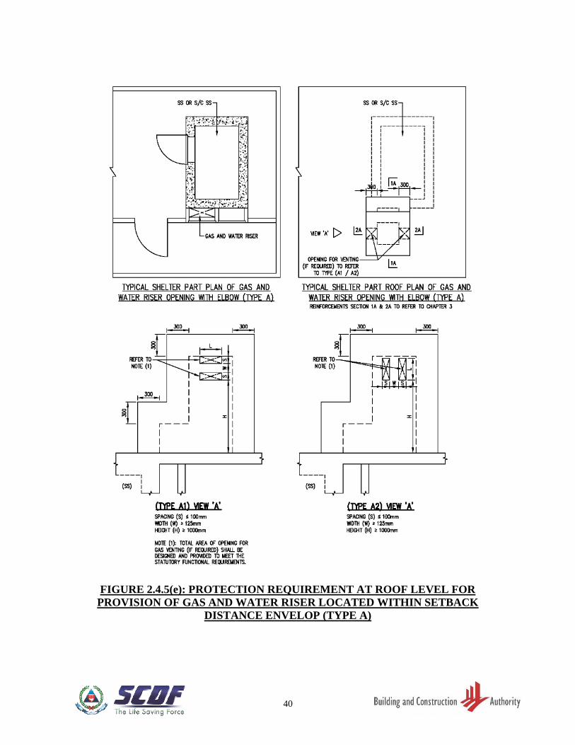
FIGURE 2.4.5(e) PROTECTION REQUIREMENT AT ROOF LEVEL FOR
PROVISION OF GAS AND WATER RISER LOCATED
WITHIN SETBACK DISTANCE ENVELOP (TYPE A) ………. 40
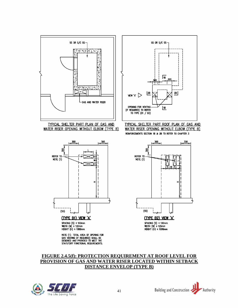
FIGURE 2.4.5(f) PROTECTION REQUIREMENT AT ROOF LEVEL FOR
PROVISION OF GAS AND WATER RISER LOCATED
WITHIN SETBACK DISTANCE ENVELOP (TYPE B) ………. 41
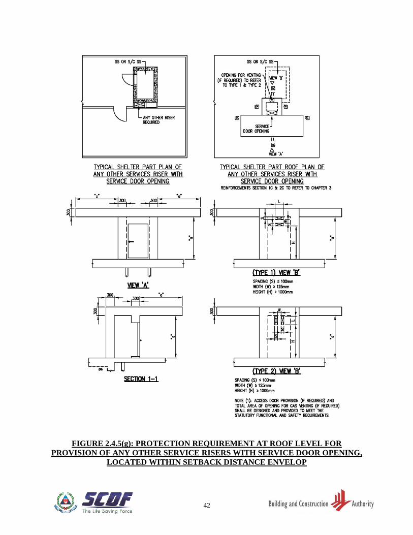
FIGURE 2.4.5(g)
PROTECTION REQUIREMENT AT ROOF LEVEL FOR
PROVISION OF ANY OTHER SERVICE RISERS WITH
SERVICE DOOR OPENING, LOCATED WITHIN SETBACK
DISTANCE ENVELOP …………………………………………… 42
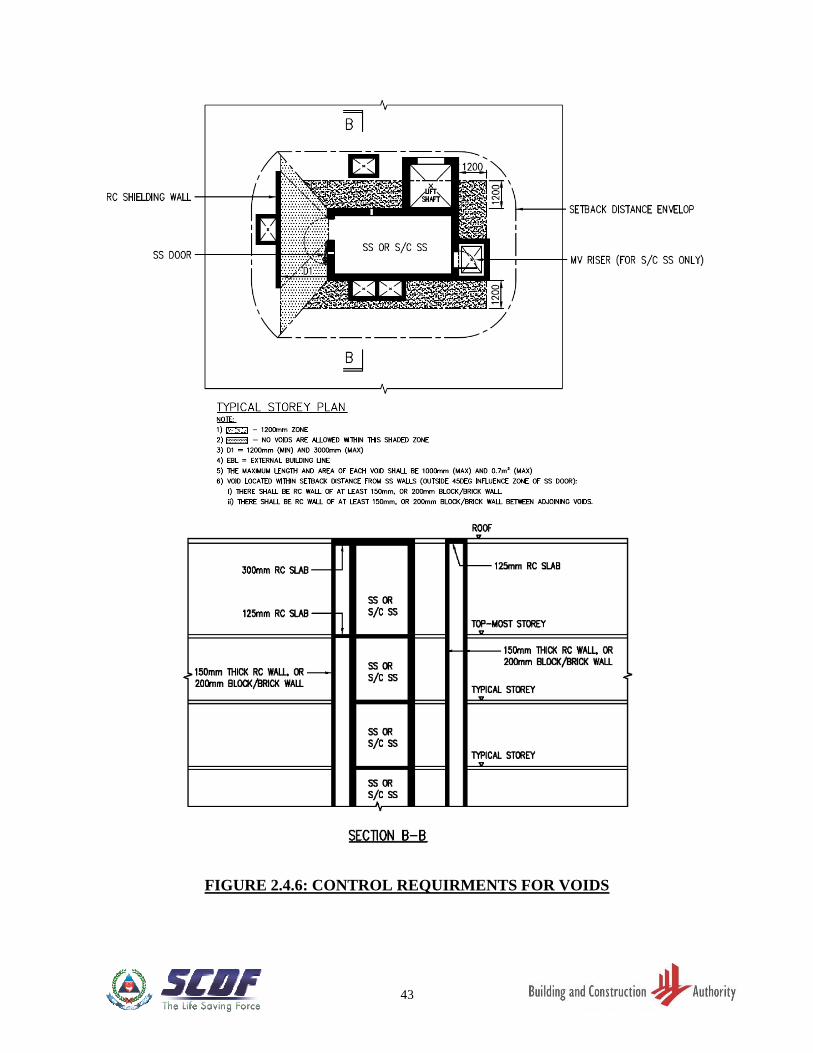
FIGURE 2.4.6 CONTROL REQUIRMENTS FOR VOIDS …………………….. 43
FIGURE 2.5.1(a) SS DOOR FRAME WITH SINGLE DOOR REBATE …………. 44
FIGURE 2.5.1(b) SS DOOR FRAME WITH DOUBLE DOOR REBATES ………. 44
FIGURE 2.5.2 STAIRCASE SS COMPARTMENT WITH CLEAR DOOR
SWING ZONE OF FIRE DOOR AND INTERNAL OR
EXTERNAL SS DOOR OPENING IN SAME LOCATION …… 45
FIGURE 2.5.3(a) CONCRETE WALL SEGMENT AT SS DOOR ………………... 46
FIGURE 2.5.3(b) SS DOOR KERB …………………………………………………... 46
FIGURE 2.5.3(c) CONCRETE WALL SEGMENT AT S/C SS DOORS AND
BLAST HATCH …………………………………………………… 47
FIGURE 2.5.3(d) S/C SS DOOR KERB ……………………………………………… 47
FIGURE 2.5.4(a) SHIELDING FOR SS DOOR …………………………………….. 48
FIGURE 2.5.4(b) SHIELDING FOR SS DOOR …………………………………….. 48
FIGURE 2.5.4(c) SHIELDING FOR SS DOOR …………………………………….. 49
FIGURE 2.5.4(d) SHIELDING FOR SS DOOR …………………………………….. 49
FIGURE 2.5.4(e) SHIELDING FOR SS DOOR …………………………………….. 50
FIGURE 2.5.4(f) SHIELDING FOR SS DOOR …………………………………….. 50
FIGURE 2.5.5 REQUIREMENTS FOR STRENGTHENING CEILING SLAB
IN FRONT OF SS DOOR ………………………………………… 51
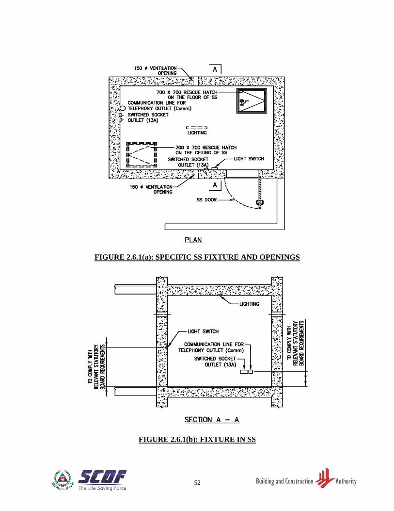
FIGURE 2.6.1(a) SPECIFIC SS FIXTURE AND OPENINGS …………………….. 52
FIGURE 2.6.1(b) FIXTURE IN SS …………………………………………………… 52
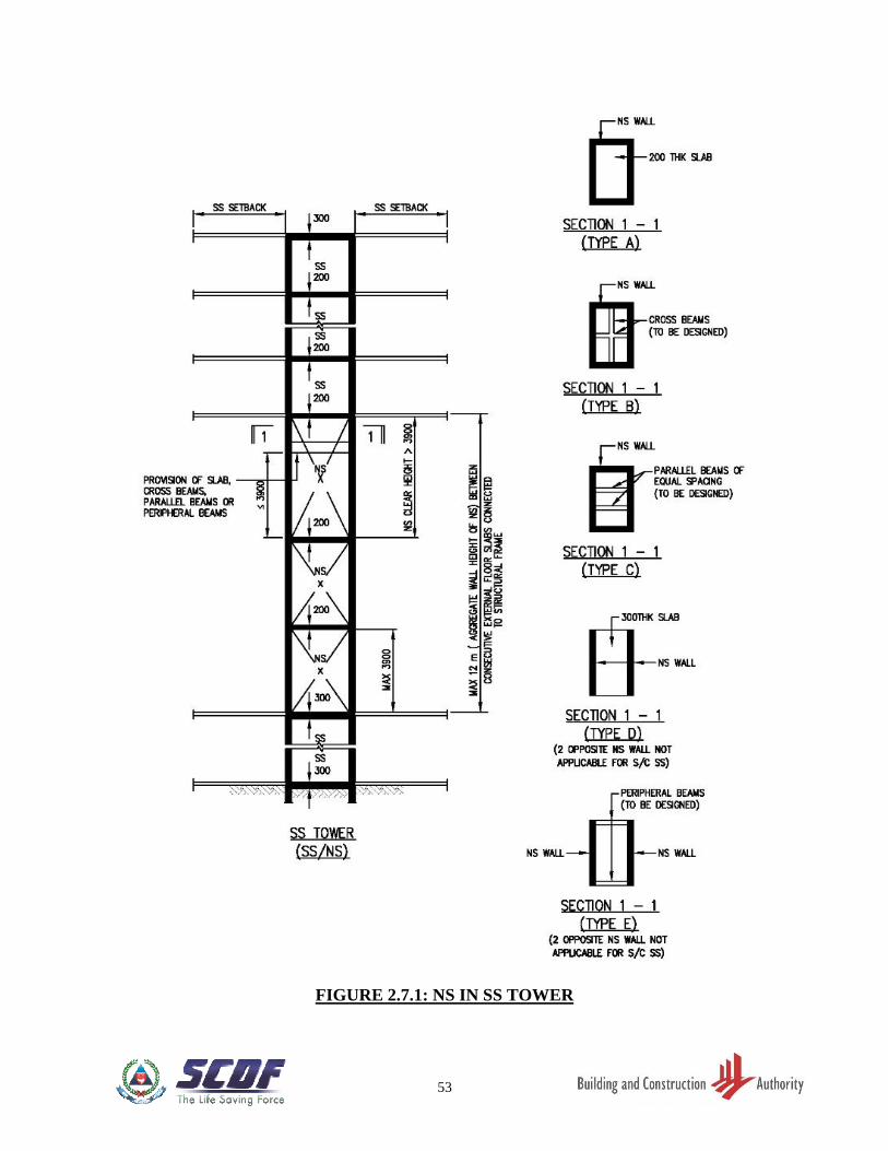
FIGURE 2.7.1 NS IN SS TOWER ……………………………………………….… 53
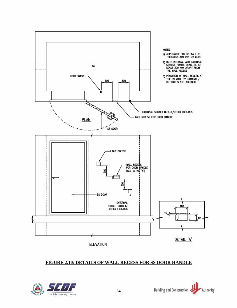
FIGURE 2.10 DETAILS OF WALL RECESS FOR SS DOOR HANDLE ……. 54
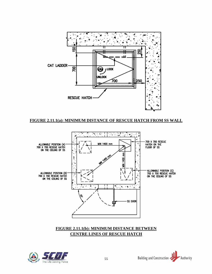
FIGURE 2.11.1(a) MINIMUM DISTANCE OF RESCUE HATCH FROM SS
WALL ………………………………………………………………. 55
FIGURE 2.11.1(b) MINIMUM DISTANCE BETWEEN CENTRE LINES OF
RESCUE HATCH …………………………………………………. 55
FIGURE 2.11.1(c) MINIMUM DIMENSIONS OF RESCUE HATCH …………….. 56
FIGURE 2.11.2 DETAILS OF CAT LADDER TO SS WALL …………………… 57
FIGURE 2.12.1(a) SECTION X-X OF S/C SS WITH SS/NS ………………………... 58
FIGURE 2.12.1(b) PROTECTION CARCASS OF S/C SS TOWER ……………….. 59
FIGURE 2.12.1(c) PROTECTION CARCASS OF S/C SS TOWER ……………….. 60
FIGURE 2.12.1(d) PLAN OF NON-SHELTER (NS) ABOVE TOP-MOST S/C SS
COMPARTMENT ………………………………………………… 61
FIGURE 2.12.1(e) PLAN OF TOP-MOST S/C SS COMPARTMENT ……………... 62
FIGURE 2.12.1(f) TYPICAL PLAN OF S/C SS COMPARTMENT ……………….. 63
VIII
FIGURE 2.12.1(g) PLAN OF BOTTOM-MOST S/C SS COMPARTMENT ………. 64
FIGURE 2.12.1(h) PLAN OF NS IMMEDIATELY BELOW BOTTOM-MOST
S/C SS COMPARTMENT ………………………………………… 65
FIGURE 2.12.2(a) PLAN OF NS AT FIRE DISCHARGE STOREY ………………. 66
FIGURE 2.12.2(b) SS WITH NS ABOVE TOP-MOST SS COMPARTMENT,
INTERMEDIATE SS COMPARTMENT AND SS WITH NS
BELOW BOTTOM-MOST SS COMPARTMENT ……………... 67
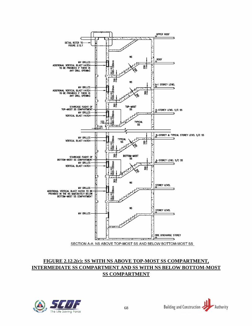
FIGURE 2.12.2(c) SS WITH NS ABOVE TOP-MOST SS COMPARTMENT,
INTERMEDIATE SS COMPARTMENT AND SS WITH NS
BELOW BOTTOM-MOST SS COMPARTMENT ……………... 68
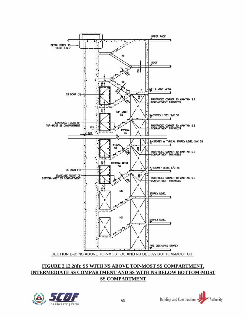
FIGURE 2.12.2(d) SS WITH NS ABOVE TOP-MOST SS COMPARTMENT,
INTERMEDIATE SS COMPARTMENT AND SS WITH NS
BELOW BOTTOM-MOST SS COMPARTMENT ……………... 69
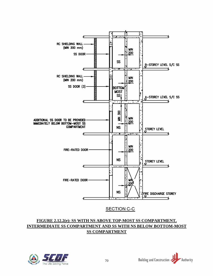
FIGURE 2.12.2(e) SS WITH NS ABOVE TOP-MOST SS COMPARTMENT,
INTERMEDIATE SS COMPARTMENT AND SS WITH NS
BELOW BOTTOM-MOST SS COMPARTMENT ……………... 70
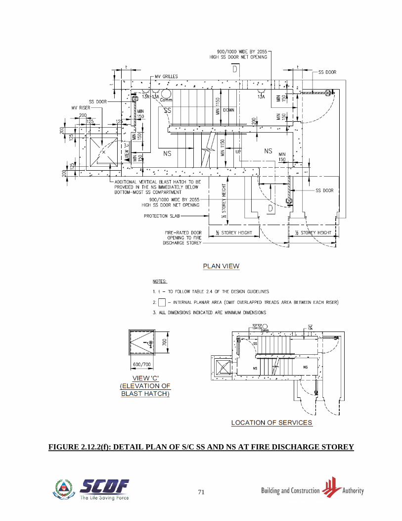
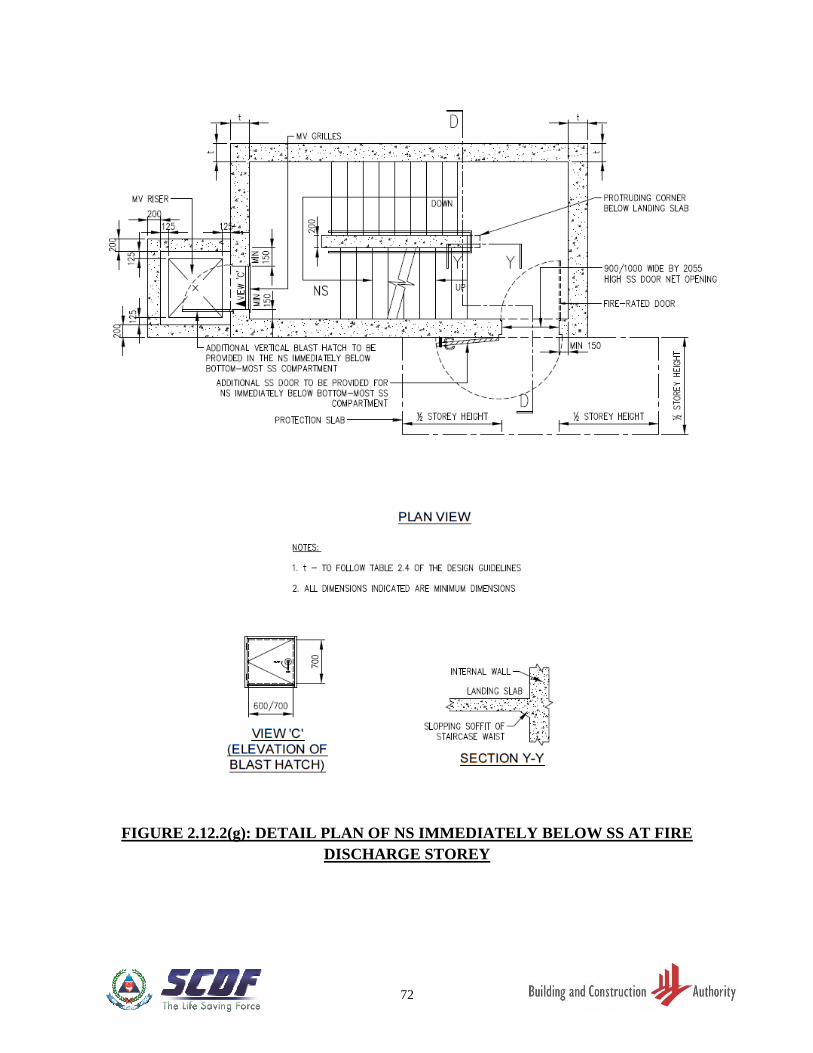
FIGURE 2.12.2(f) DETAIL PLAN OF SS AND NS AT FIRE DISCHARGE
STOREY …………………………………………………………… 71
FIGURE 2.12.2(g) DETAIL PLAN OF NS IMMEDIATELY BELOW SS AT FIRE
DISCHARGE STOREY …………………………………………... 72
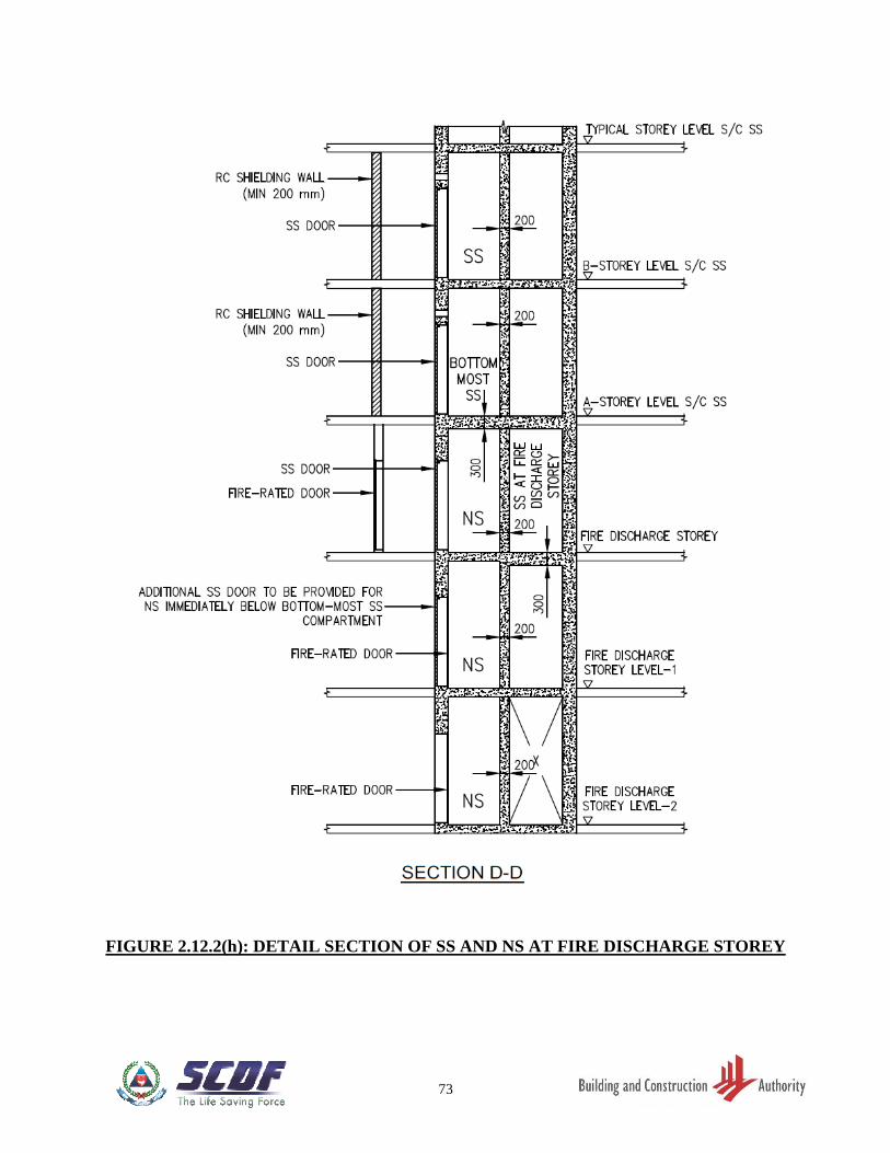
FIGURE 2.12.2(h) DETAIL SECTION OF SS AND NS AT FIRE DISCHARGE
STOREY …………………………………………………………… 73
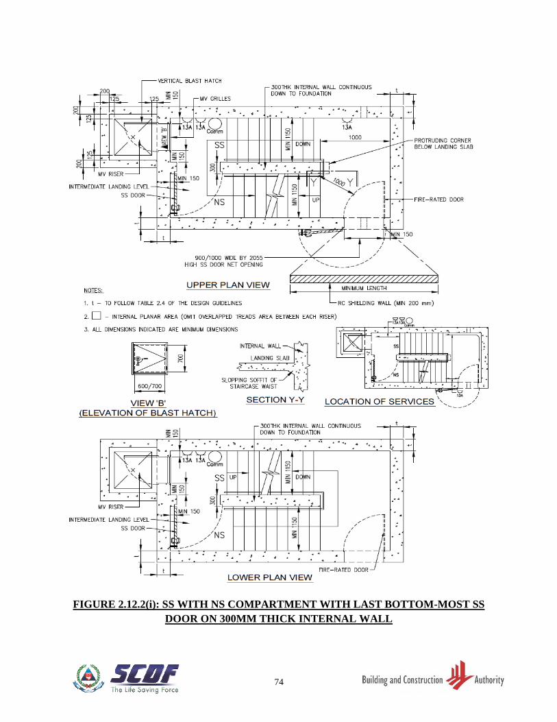
FIGURE 2.12.2(i) SS WITH NS COMPARTMENT WITH LAST BOTTOM-
MOST SS DOOR ON 300MM THICK INTERNAL WALL …... 74
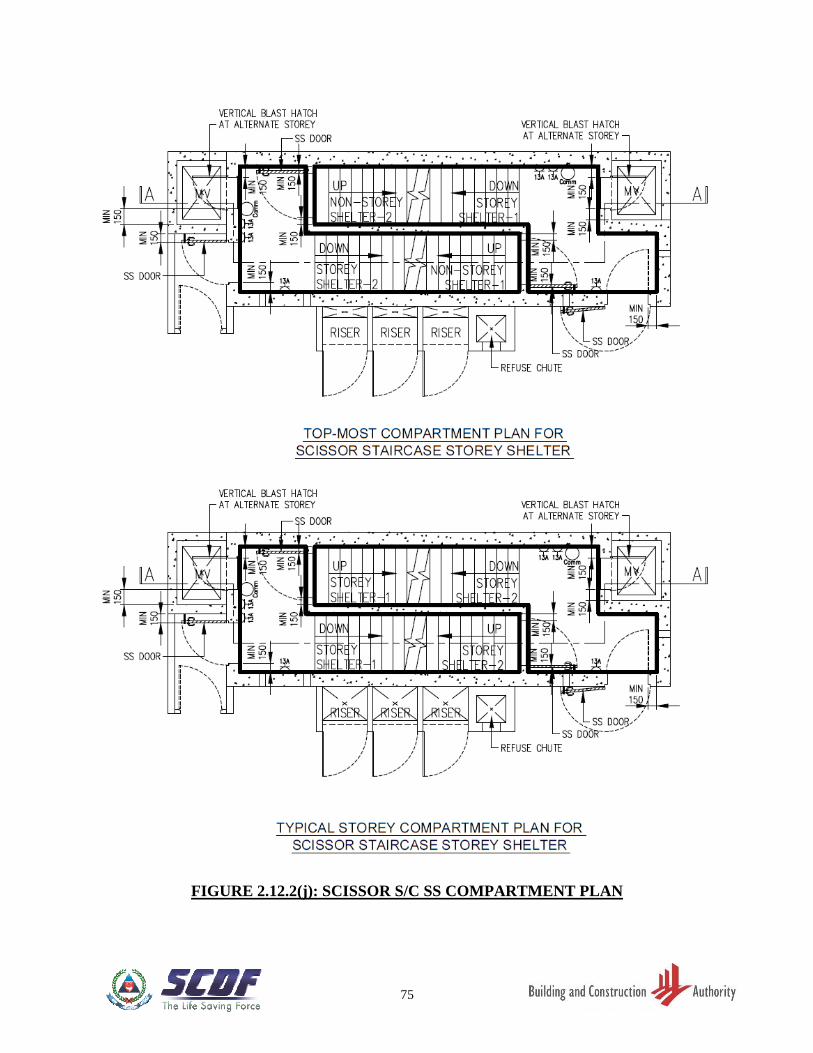
FIGURE 2.12.2(j) SCISSOR S/C SS COMPARTMENT PLAN ……………………. 75
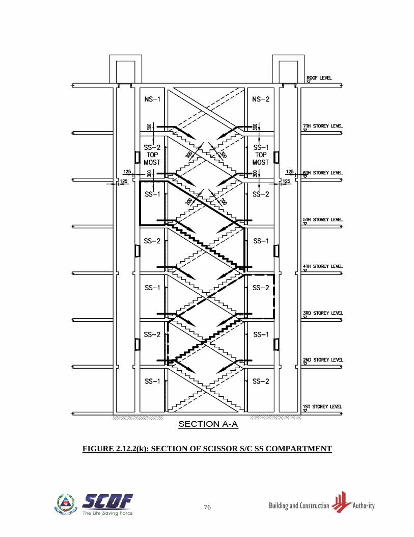
FIGURE 2.12.2(k) SECTION OF SCISSOR S/C SS COMPARTMENT …………… 76
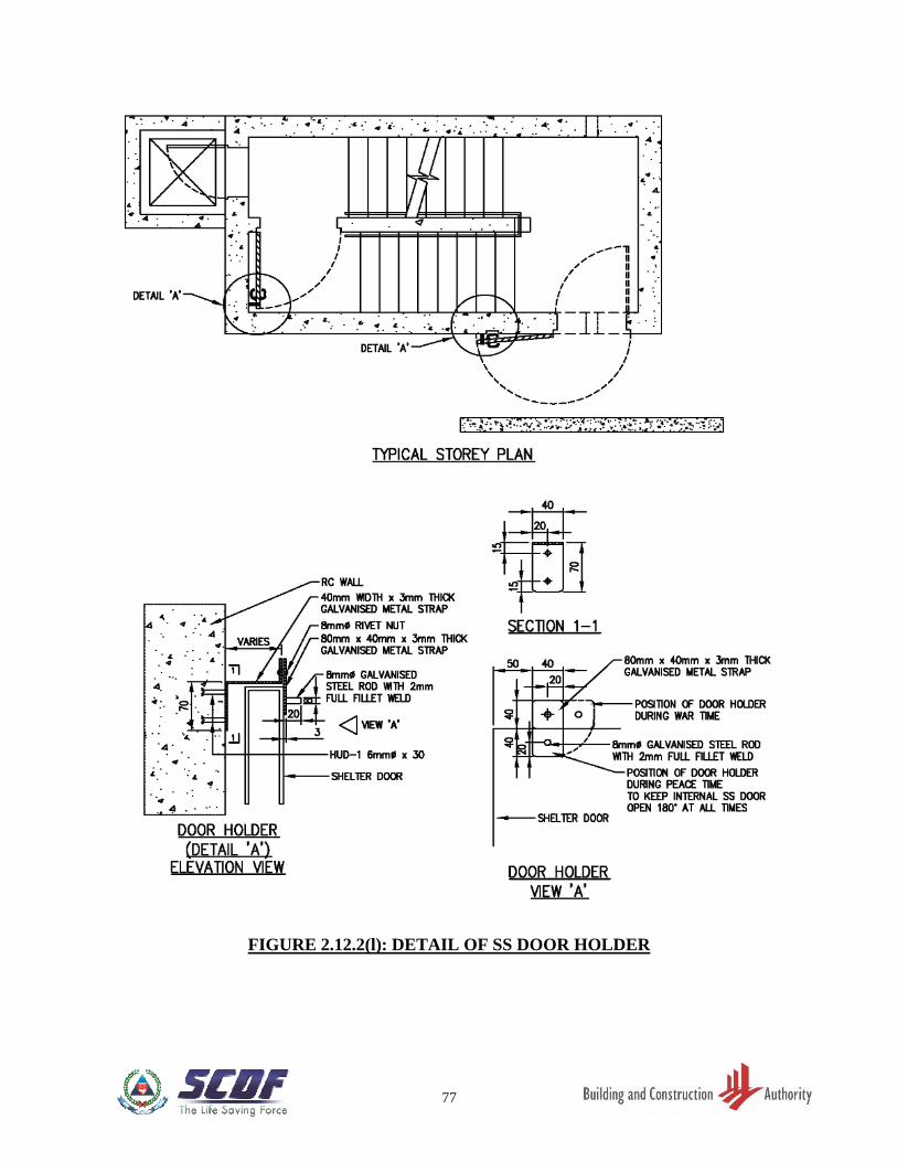
FIGURE 2.12.2(l) DETAIL OF SS DOOR HOLDER ……………………………….. 77
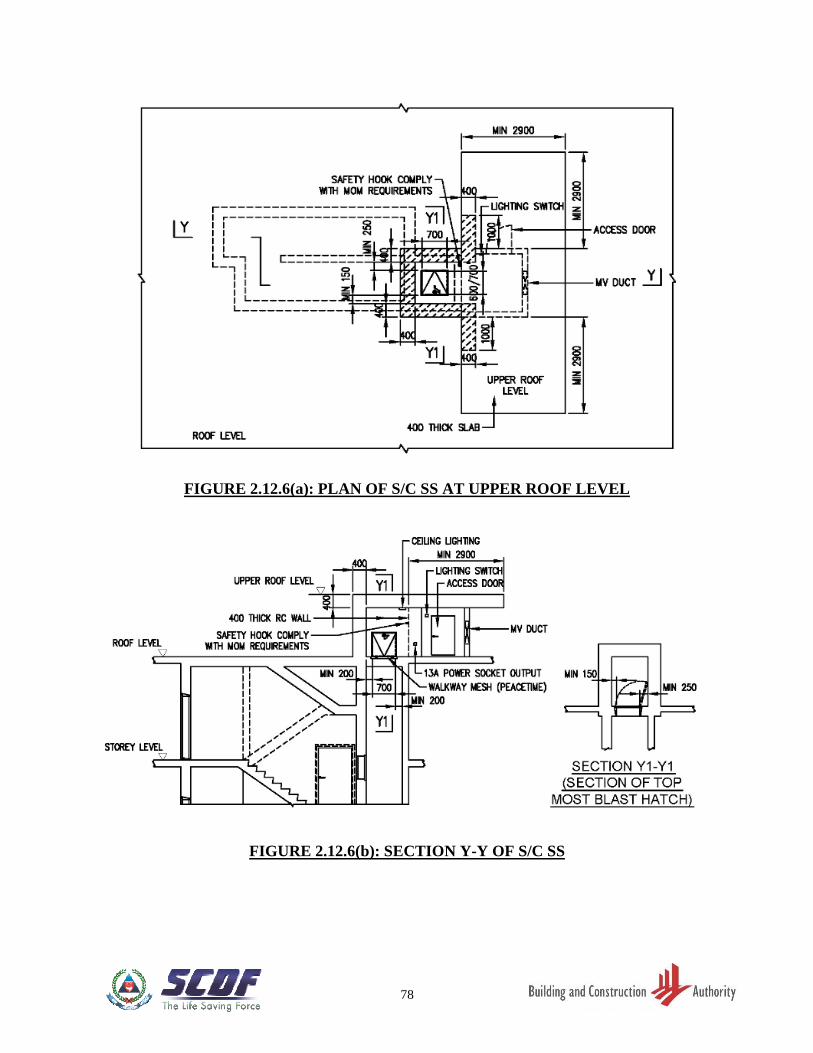
FIGURE 2.12.6(a) PLAN OF S/C SS AT UPPER ROOF LEVEL …………………... 78
FIGURE 2.12.6(b) SECTION Y-Y OF S/C SS ………………………………………… 78
FIGURE 2.12.6(c) PLAN OF S/C SS AT UPPER ROOF LEVEL …………………... 79
FIGURE 2.12.6(d) SECTION Z-Z OF S/C SS ………………………………………… 79
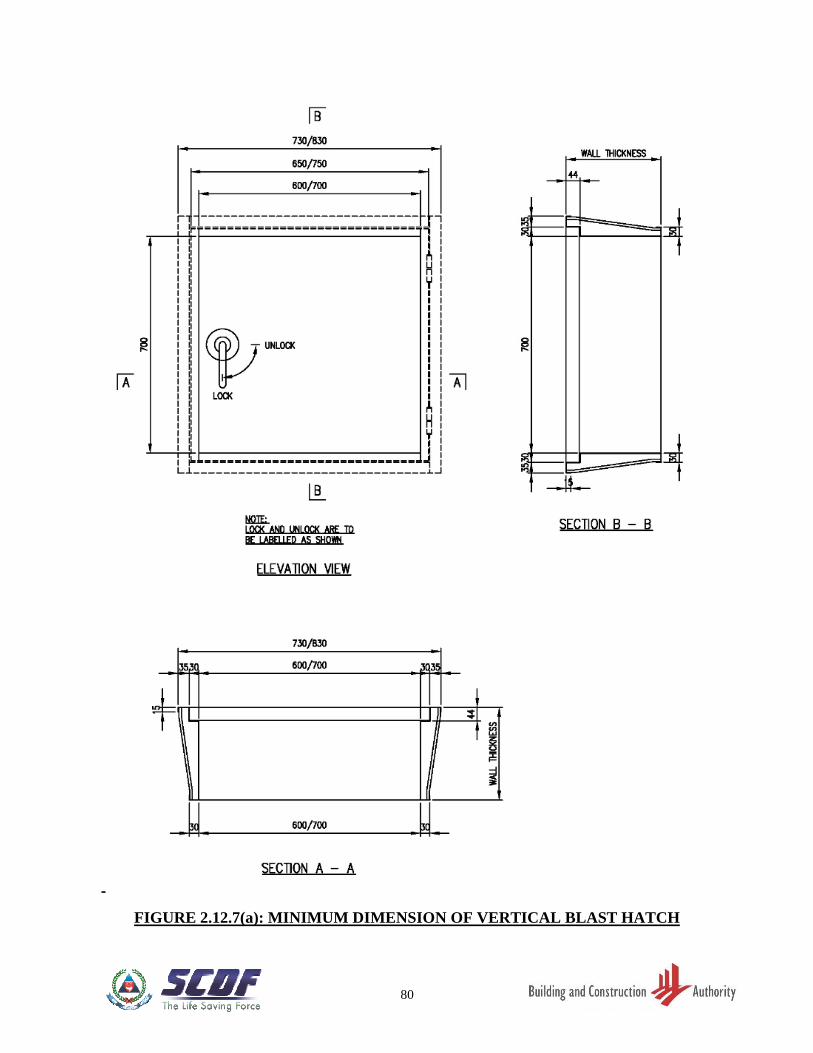
FIGURE 2.12.7(a) MINIMUM DIMENSION OF VERTICAL BLAST
HATCH …………………………………………………………….. 80
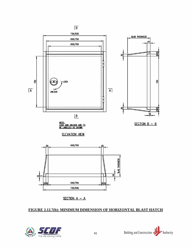
FIGURE 2.12.7(b) MINIMUM DIMENSION OF HORIZONTAL BLAST
HATCH …………………………………………………………..… 81
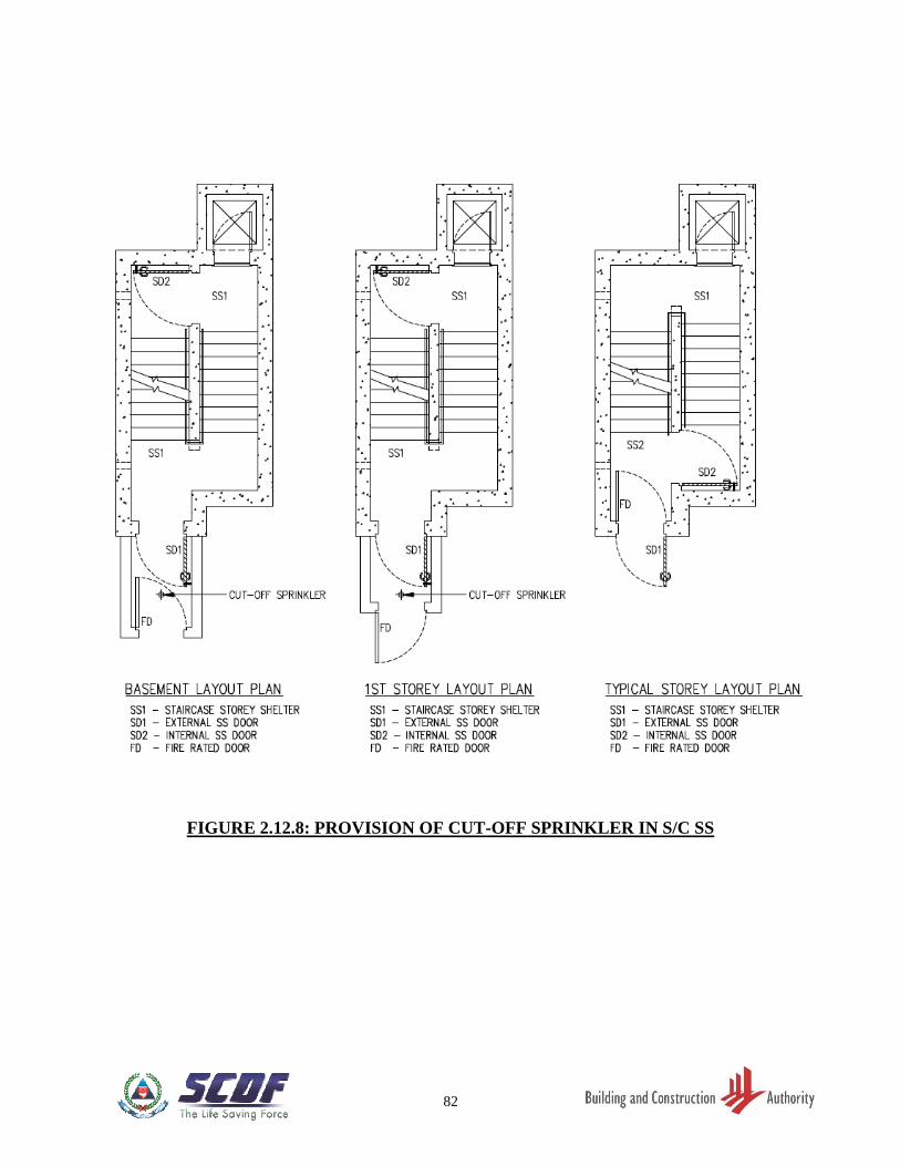
FIGURE 2.12.8 PROVISION OF CUT-OFF SPRINKLER IN S/C SS ………….. 82
LIST OF TABLES (CHAPTER 3)
TABLE 3.3.4 ACTION COMBINATION AND VALUES OF PARTIAL
SAFETY FACTORS FOR ULTIMATE LIMIT STATE ………. 94
TABLE 3.4.2.1 MINIMUM REINFORCEMENTS OF SS OR NS WALLS ……. 94
TABLE 3.5.2 MINIMUM TENSION LAP AND ANCHORAGE LENGTH …. 94
IX
LIST OF FIGURES (CHAPTER 3)
FIGURE 3.3.3 SHIELDED NS WALLS OF SS TOWER (2 OPPOSITE NS
WALLS NOT APPLICABLE FOR S/C SS TOWER) ………….. 95
FIGURE 3.3.4(a) UNSHIELDED NS WALL(S) OF SS TOWER ………………….. 96
FIGURE 3.3.4(b) UNSHIELDED NS WALL(S) OF SS TOWER (2 OPPOSITE
NS WALLS NOT APPLICABLE FOR S/C SS TOWER) ……… 96
FIGURE 3.3.4(c) SHIELDED NS WALL(S) OF S/C SS TOWER ………………… 97
FIGURE 3.3.4(d) UNSHIELDED NS WALL OF S/C SS TOWER ………………... 98
FIGURE 3.5.4(a) PLAN OF SS WALL ………………………………………………. 99
FIGURE 3.5.4(b) SECTIONAL DETAILS OF SS SLABS/ WALLS ……………… 100
FIGURE 3.5.4(c) SECTIONAL DETAILS OF SS SLABS/ WALLS ……………… 101
FIGURE 3.5.4(d)(i) DETAILS OF SS WALL REINFORCEMENT BARS
NEAR SS DOOR ……………...…………………………………… 102
FIGURE 3.5.4(d)(ii) DETAILS OF S/C SS WALL REINFORCEMENT BARS
NEAR S/C SS DOOR ……………………………………………… 103
FIGURE 3.5.4(e) TYPICAL DETAILS OF EMBEDDED CONDUIT IN SS
WALL ………………………………………...…………………….. 104
FIGURE 3.5.4(f) TYPICAL DETAILS OF TRIMMER BARS FOR
VENTILATION SLEEVE ………………………………………… 105
FIGURE 3.5.4(g) TYPICAL DETAILS OF REINFORCEMENT BARS AT
WALL RECESS …………………………………………………… 105
FIGURE 3.5.4(h) DETAILS OF SHEAR LINKS IN SS SLABS/WALLS ………… 106
FIGURE 3.5.4(i) DETAILS OF SS SLAB REINFORCEMENT NEAR RESCUE
HATCH …………………………………………………………….. 107
FIGURE 3.5.4(j) REINFORCEMENT PLAN DETAILS FOR S/C SS …………… 108
FIGURE 3.5.4(k) SECTIONAL DETAILS OF SS SLABS/ WALLS
FOR S/C SS ………………………………………………………… 109
FIGURE 3.5.4(l) SECTIONAL DETAILS OF SS SLABS/ WALLS
FOR S/C SS ………………………………………………………… 110
FIGURE 3.5.4(m) SECTIONAL DETAILS OF SS SLABS/ WALLS
FOR S/C SS ………………………………………………………… 111
FIGURE 3.5.5(a) PLAN OF SS WALLS WITH PRECAST SS DOOR FRAME
PANEL (TYPE 1) ………………………………………………….. 112
FIGURE 3.5.5(b)
DETAILS AND SECTIONS OF PRECAST SS DOOR
FRAME PANEL WITH VENTILATION SLEEVE ABOVE IT
(TYPE 1) ……………………………………………………………. 113
FIGURE 3.5.5(c) SECTIONS OF PRECAST SS DOOR FRAME PANEL
WITH VENTILATION SLEEVE ABOVE IT (TYPE 1) ………. 114
FIGURE 3.5.5(d)
DETAILS AND SECTIONS OF PRECAST SS DOOR
FRAME WITH VENTILATION SLEEVE ALONG ITS SIDE
(TYPE 1) ……………………………………………………………. 115
FIGURE 3.5.5(e)
DETAILS AND SECTIONS OF PRECAST SS DOOR
FRAME WITH VENTILATION SLEEVE ALONG ITS SIDE
(TYPE 1) ……………………………………………………………. 116
FIGURE 3.5.5(f) PLAN OF SS WALLS WITH PRECAST SS DOOR FRAME
PANEL (TYPE 2) ………………………………………………….. 117
X
FIGURE 3.5.5(g)
DETAILS AND SECTIONS OF PRECAST SS DOOR
FRAME PANEL WITH VENTILATION SLEEVE ABOVE IT
(TYPE 2) ……………………………………………………………. 118
FIGURE 3.5.5(h) SECTIONS OF PRECAST SS DOOR FRAME PANEL
WITH VENTILATION SLEEVE ABOVE IT (TYPE 2) ………. 119
FIGURE 3.5.5(i)
DETAILS AND SECTIONS OF PRECAST SS DOOR FRAME
PANEL WITH VENTILATION SLEEVE ALONG ITS SIDE
(TYPE 2) ……………………………………………………………. 120
FIGURE 3.5.5(j) SECTIONS OF PRECAST SS DOOR FRAME PANEL WITH
VENTILATION SLEEVE ALONG ITS SIDE (TYPE 2) ………. 121
FIGURE 3.5.5(k) PLAN OF SS WALLS WITH PRECAST SS DOOR FRAME
PANEL (TYPE 3) ………………………………………………….. 122
FIGURE 3.5.5(l) DETAILS OF PRECAST SS DOOR FRAME PANEL
(TYPE 3) ……………………………………………………………. 123
FIGURE 3.5.5(m) SECTIONS OF PRECAST SS DOOR FRAME PANEL
(TYPE 3) ……………………………………………………………. 124
FIGURE 3.5.5(n) SECTIONS OF PRECAST SS DOOR FRAME PANEL
(TYPE 3) ……………………………………………………………. 125
FIGURE 3.5.5(o)(i)
TYPICAL DETAILS AND SECTIONS OF
REINFORCEMENTS AT VENTILATION SLEEVE
LOCATION ………………………………………………………... 126
FIGURE 3.5.5(o)(ii)
TYPICAL DETAILS AND SECTIONS OF
REINFORCEMENTS AT VENTILATION SLEEVE
LOCATION ………………………………………………………... 127
FIGURE 3.5.5(p) PLANS AND DETAILS OF SS SLABS FOR S/C SS
PRECAST FLIGHT ……………………………………………….. 128
FIGURE 3.5.6.1(a) PLAN OF 3 VOLUMETRIC COMPONENTS OF PRECAST
S/C SS ………………………………………………………………. 129
FIGURE 3.5.6.1(b) INTERNAL ELEVATION VIEW 'A' OF 3 VOLUMETRIC
COMPONENTS OF PRECAST S/C SS………………………….. 130
FIGURE 3.5.6.1(c) BLAST DOOR AND VENTILATION SLEEVE ………………... 131
FIGURE 3.5.6.1(d) HOLLOW CORE SHAPE ………………………………………... 132
FIGURE 3.5.6.2(a)(i) PLAN OF PRECAST S/C SS (COMPONENT 'A')……………… 133
FIGURE 3.5.6.2(a)(ii)
PLAN OF PRECAST S/C SS WALL WITH
REINFORCEMENT DETAILS AT BLAST HATCH
OPENING (S/C SS COMPONENT 'A') …………………………. 133
FIGURE 3.5.6.2(a)(iii) PLAN OF PRECAST S/C SS WALL WITH
REINFORCEMENT DETAILS ABOVE BLAST HATCH
OPENING (S/C SS COMPONENT 'A') …………………………. 134
FIGURE 3.5.6.2(a)(iv) SECTION D-D (S/C SS COMPONENT 'A') …………………….. 134
FIGURE 3.5.6.2(a)(v) SECTION E-E (S/C SS COMPONENT 'A') …………………….. 134
FIGURE 3.5.6.2(a)(vi) SECTION F-F (S/C SS COMPONENT 'A') ……………………... 135
FIGURE 3.5.6.2(a)(vii) SECTION G-G (S/C SS COMPONENT 'A') ……………………. 136
FIGURE 3.5.6.2(a)(viii) SECTION H-H (S/C SS COMPONENT 'A') ……………………. 136
FIGURE 3.5.6.2(b)(i) PLAN OF PRECAST S/C SS (S/C SS COMPONENT 'B') …….. 137
FIGURE 3.5.6.2(b)(ii)
PLAN OF PRECAST S/C SS WALL WITH
REINFORCEMENT DETAILS
(S/C SS COMPONENT 'B') ………………………………………. 137
XI
FIGURE 3.5.6.2(b)(iii) INTERNAL ELEVATION VIEW 'B' (S/C SS COMPONENT
'B') …………………………………………………………………... 138
FIGURE 3.5.6.2(b)(iv) SECTION K1-K1 (S/C SS COMPONENT 'B') ………………….. 139
FIGURE 3.5.6.2(b)(v) SECTION K2-K2 (S/C SS COMPONENT 'B') ………………….. 139
FIGURE 3.5.6.2(b)(vi) SECTION L-L (S/C SS COMPONENT 'B') …………………….. 139
FIGURE 3.5.6.2(c)(i) PLAN OF PRECAST S/C SS (COMPONENT 'C') ……………... 141
FIGURE 3.5.6.2(c)(ii) PLAN OF PRECAST S/C SS WALL WITH
REINFORCEMENT DETAILS (S/C SS COMPONENT 'C') …. 141
FIGURE 3.5.6.2(c)(iii) SECTION S-S (S/C SS COMPONENT 'C') ……………………... 142
FIGURE 3.5.6.2(c)(iv) SECTION T-T (S/C SS COMPONENT 'C') …………………….. 142
FIGURE 3.5.6.2(c)(v) SECTION U-U AT VENTILATION SLEEVE (S/C SS
COMPONENT 'C') ………………………………………………... 143
FIGURE 3.5.6.2(c)(vi) SECTION X-X AT VENTILATION SLEEVE (S/C SS
COMPONENT 'C') ………………………………………………... 143
FIGURE 3.5.6.2(c)(vii) SECTION V-V (S/C SS COMPONENT 'C') …………………….. 144
FIGURE 3.5.6.2(c)(viii) SECTION W-W (S/C SS COMPONENT 'C') …………………… 144
FIGURE 3.5.6.2(d) REINFORCEMENT DETAILS OF RIB ………………………… 145
FIGURE 3.5.6.2(e)
DETAILS OF REINFORCEMENT NEAR DOOR FRAME
AND AT ELECTRICAL FIXTURES ON INTERNAL FACE
OF PRECAST SSS ………………………………………………… 146
FIGURE 3.5.6.2(f) DETAILS OF TRIMMER BARS FOR VENTILATION
SLEEVE ……………………………………………………………. 147
FIGURE 3.5.6.2(g) DETAILS OF TRIMMER BARS FOR WALL RECESS FOR
PRECAST S/C SS DOOR HANDLE …………………………….. 147
FIGURE 3.5.6.2(h) ELECTRICAL FIXTURES ON EXTERNAL FACE OF
PRECAST S/C SS ………………………………………………….. 147
FIGURE 3.5.6.2(i) REINFORCEMENT IN HOLLOW CORES ……………………. 148
FIGURE 3.5.6.2(j) REINFORCEMENT IN HOLLOW CORES OF PRECAST
S/C SS ………………………………………………………………. 148
FIGURE 3.5.6.2(k) REINFORCEMENT LAPPING IN HOLLOW CORES ……….. 149
FIGURE 3.5.6.3(a)
SPLICE SLEEVE CONNECTION DETAILS BETWEEN
PRECAST S/C SS AND CAST IN-SITU ELEMENT AND
BOLT CONNECTION DETAILS BETWEEN TWO PRECAST
S/C SS ………………………………………………………………. 150
FIGURE 3.5.6.3(b) SPLICE SLEEVE CONNECTION DETAILS FOR PRECAST
S/C SS TOWER ……………………………………………………. 150
FIGURE 3.5.6.3(c) CONNECTION DETAILS BETWEEN LOWER AND UPPER
PRECAST S/C SS ………………………………………………….. 151
FIGURE 3.5.6.4(a) DETAILED REINFORCEMENT OF PRECAST SLAB AND
CAST IN-SITU CONCRETE TOPPING ………………………... 153
FIGURE 3.5.6.4(b) CONNECTION DETAILS BETWEEN PRECAST S/C SS AND
CAST IN-SITU WALL ……………………………………………. 154
FIGURE 3.6.1(a) MOUNTING OF SERVICES ON EXTERNAL WALL
OF A SS …………………………………………………………….. 155
FIGURE 3.6.1(b) TYPICAL DETAILS OF EMBEDDED SOCKET/SWITCH ….. 156
FIGURE 3.6.2 ENCASEMENT DETAILS OF WATER/ GAS SERVICE
PIPES PENETRATING THROUGH SS WALLS ……………… 157
XII
FIGURE 3.6.3(a) REINFORCEMENT DETAILS OF REFUSE CHUTE ABOVE
ROOF LEVEL WITHIN SS SETBACK DISTANCE …………... 158
FIGURE 3.6.3(b)
REINFORCEMENT DETAILS OF RC STRUCTURES
ABOVE ROOF LEVEL FOR GAS RISER WITHIN SS
SETBACK DISTANCE …………………………………………… 159
FIGURE 3.6.3(c) REINFORCEMENT DETAILS OF RC STRUCTURES
ABOVE ROOF LEVEL FOR ANY OTHER SERVICE RISER
WITHIN SS SETBACK DISTANCE …………………………….. 160
LIST OF FIGURES (CHAPTER 4) FIGURE 4.2(a) POSITION OF VENTILATION SLEEVES …………………….. 163
FIGURE 4.2(b) SECTIONAL VIEWS OF VENTILATION SLEEVES ………… 164
FIGURE 4.2(c) LOCATION OF VENTILATION SLEEVES …………………… 165
FIGURE 4.3.1(b) MINIMUM CLEARANCE FROM INTERNAL FACE OF
VENTILATION SLEEVE ………………………………………… 166
FIGURE 4.3.2 PERFORATED ACCESS PANEL BELOW VENTILATION
SLEEVE ……………………………………………………………. 167
FIGURE 4.4 DETAILS OF VENTILATION SLEEVE AND
FRAGMENTATION PLATE …………………………………….. 168
LIST OF FIGURES (CHAPTER 5) FIGURE 5.3 MOUNTING OF REMOVABLE KERB ………………………… 170
FIGURE 5.4(a) LOCATION OF NOTICE ON SS DOOR ……………………….. 171
FIGURE 5.4(b) SAMPLE SS DOOR NOTICE ……………………………………. 172
FIGURE 5.4(c) SAMPLE S/C SS DOOR NOTICE ……………………………….. 173
LIST OF TABLES (CHAPTER 8)
TABLE 8.1 LIST OF REGULATED SHELTER PRODUCT ……………….. 189
TABLE 8.2 TEST STANDARDS AND SPECIFICATIONS FOR STOREY
SHELTER DOORS ………………………………………………... 190 - 195
1
CHAPTER 1: INTRODUCTION
1.1 GENERAL
A storey shelter (SS) is designed and constructed for the protection of people against weapon
effects during a war emergency. People should not stay inside there for protection during other
peacetime emergency situations such as a fire in a building. The SS is located at a common
property area of a storey and serves the residents of the dwelling units of that storey.
1.2 PEACETIME USE
During peacetime, the SS may be used as a common facility for the residents of the storey.
Where the staircase or scissor-staircase doubles up as a SS, it is used as a fire exit staircase.
The other statutory requirements governing the design and use of the SS space for the specific
peacetime use shall also be complied with.
1.3 ABBREVIATIONS
Clause Description Abbreviation
1.1 Storey Shelter SS
2.1 Non-Shelter NS
2.1 Staircase Storey Shelter S/C SS
2.2.1 Finished Floor Level FFL
2.2.1 Gross Floor Area GFA
2
1.4 DEFINITIONS
Clause Definition Term
2.1 The space in the SS tower that is not intended for
use as a shelter.
Non-Shelter
2.1 Building exit staircase used as SS S/C SS
2.2.2 (a) Height of SS measured from its FFL to the soffit
of the SS ceiling slab.
SS Clear
Height
2.2.2 (a) Height of NS measured from its FFL to the soffit
of the NS ceiling slab.
NS Clear
Height
2.3.1 Setback to be protected by slab/trellis at ceiling
level and distance to be measured horizontally
from external face of SS wall.
Setback
Distance
2.3.2(a) The SS located below the top-most roof level Top-most SS
3
CHAPTER 2: ARCHITECTURAL REQUIREMENTS
2.1 SS OR NS FORM
The configuration of a SS or Non-Shelter (NS) on plan shall be rectangular or square shape.
In the case of a staircase storey shelter (S/C SS) and scissor S/C SS, there can be slight
deviations from the rectangular or square shape.
2.2 SIZE OF SS
2.2.1 Area and Volume
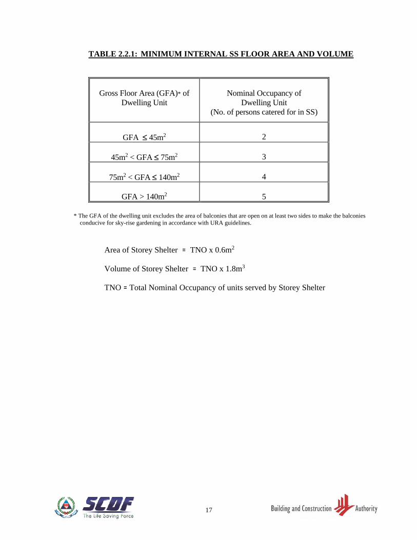
(a) The minimum internal floor area and minimum internal volume of a SS or S/C SS
shall be based on gross floor area (GFA) of dwelling unit and nominal occupancy of
dwelling unit in accordance with TABLE 2.2.1.
(b) The maximum internal floor area of a SS or S/C SS shall be 32m2.
(c) For the S/C SS, the aggregate planar area of the staircase entrance landing,
intermediate landing and the staircase treads (excluding the over-lapping tread at each
riser and area taken up by the internal SS door) of each storey is taken as its internal
floor area.
(d) The product of the internal floor area of the S/C SS and its clear height, measured from
the finished floor level (FFL) to the soffit of the ceiling staircase slab, is taken as the
internal volume of the S/C SS.
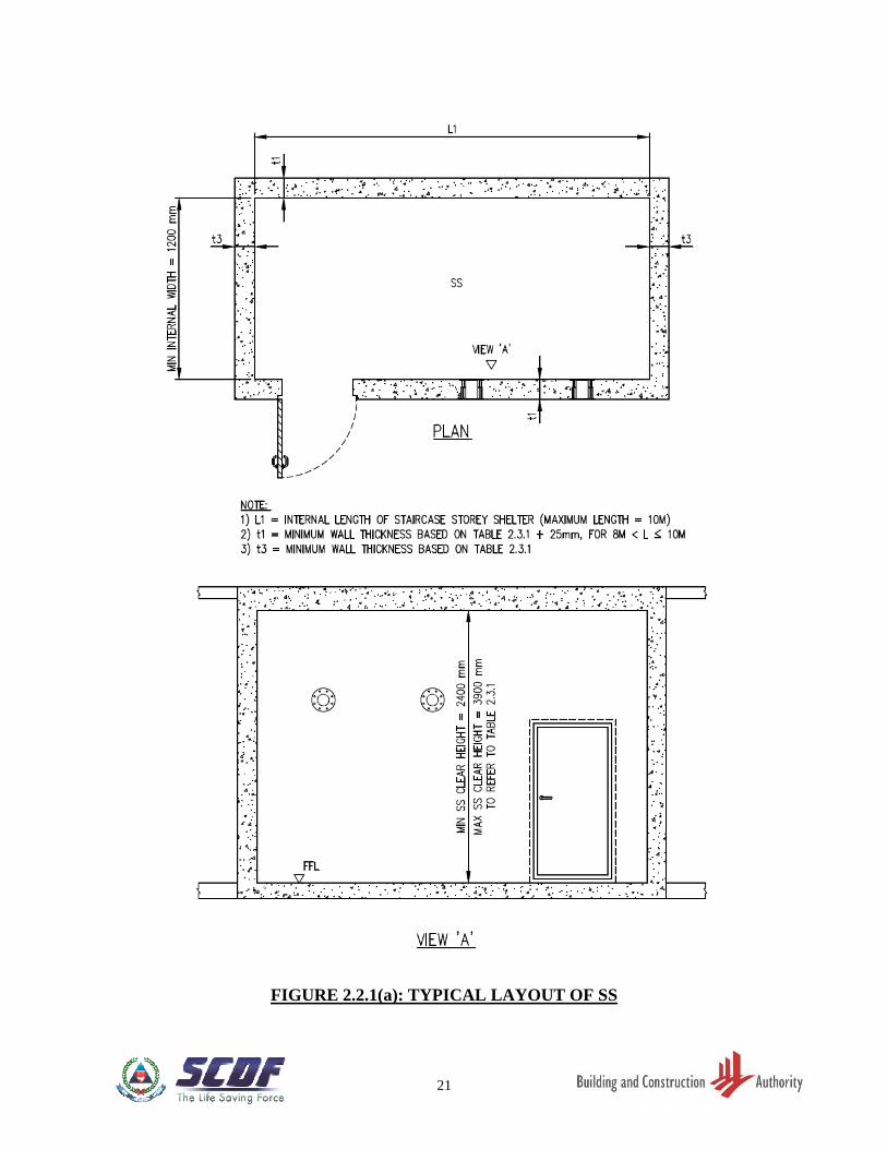
(e) The maximum internal length of any floor and roof slab of a SS shall be 10000mm.
The minimum internal width of a SS or S/C SS shall be 1200mm. Refer to FIGURE
2.2.1(a) and 2.2.1(b).
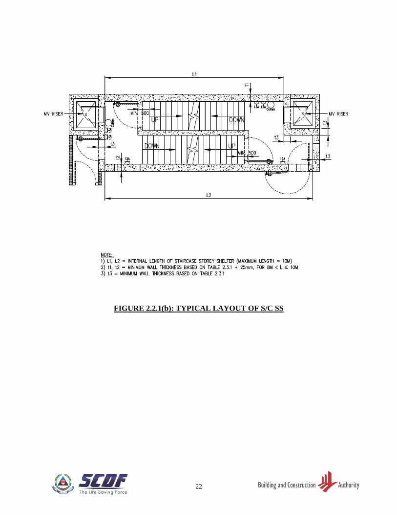
(f) For S/C SS, the minimum internal width of staircase flight shall be at least 1150mm.
See FIGURE 2.12.1(f).
(g) The ratio of the internal length to the internal width shall not exceed 3:1.
2.2.2 Heights
(a) The minimum SS clear height shall be 2400mm. Refer to FIGURE 2.2.1(a). The
minimum NS clear height shall be 2400mm.
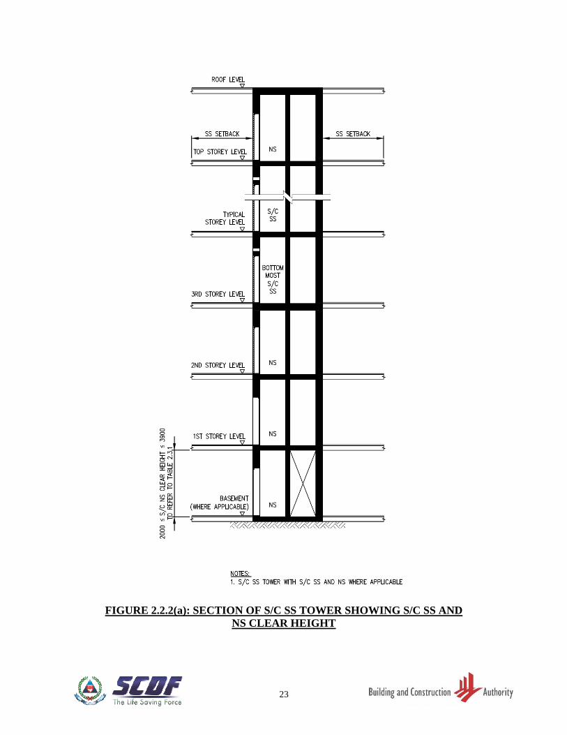
(b) The minimum S/C SS or scissor S/C SS clear height shall be 2400mm. Within the S/C
SS or scissor S/C SS tower, where the storey height deviated from the typical storey
4
height, the minimum clear height of NS in S/C SS or scissor S/C tower shall be
2000mm. Refer to FIGURE 2.2.2(a).
(c) The maximum clear height of a SS, S/C SS, scissor S/C SS and NS shall be 3900mm.
Refer to FIGURE 2.2.1(a), 2.2.2(a) and TABLE 2.3.1.
2.3 WALL AND SLAB THICKNESS OF SS AND NS
2.3.1 SS Wall Thickness
The thickness of SS wall varies accordingly to SS clear height and the setback distance. The
thickness shall comply with the following requirements:
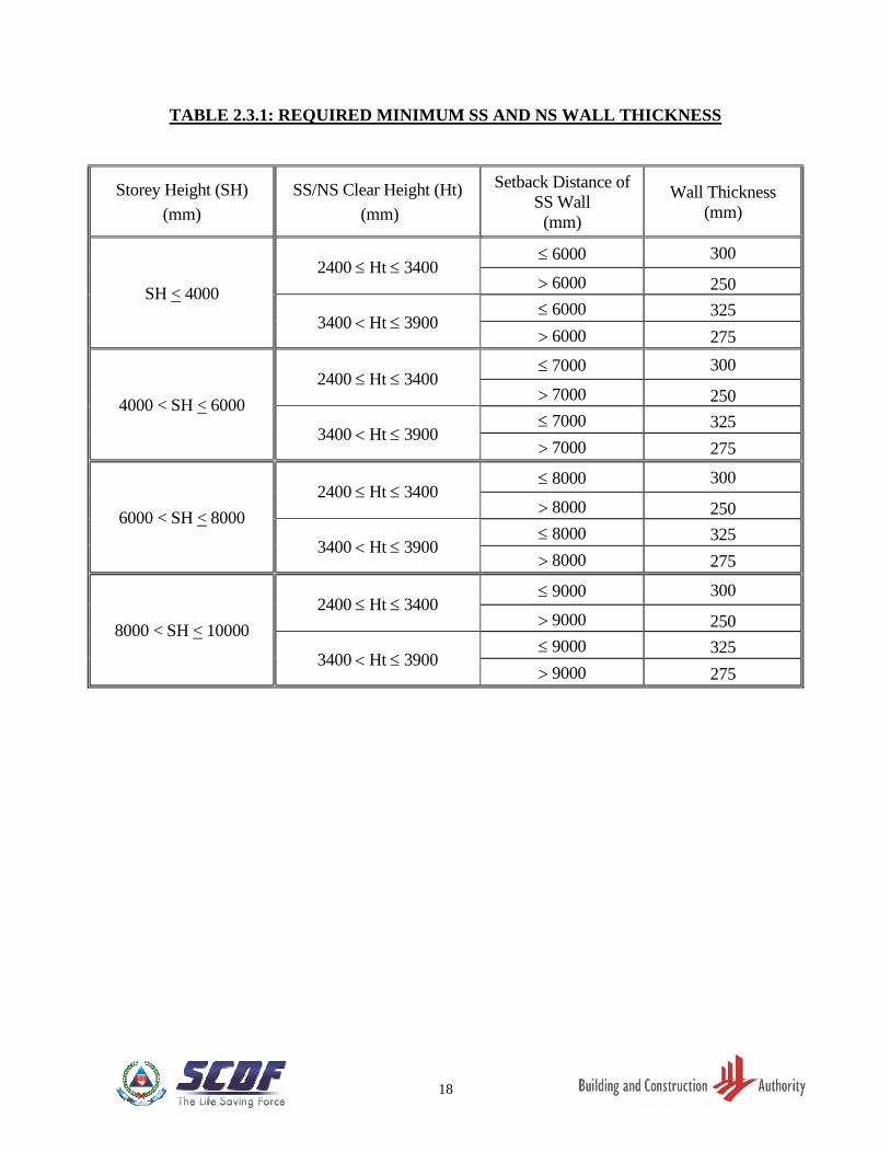
(a) The minimum SS wall thickness shall be in accordance with TABLE 2.3.1.
(b) Wall thickness of any SS or NS within the SS tower shall not be less than the wall
thickness of the SS or NS above it.
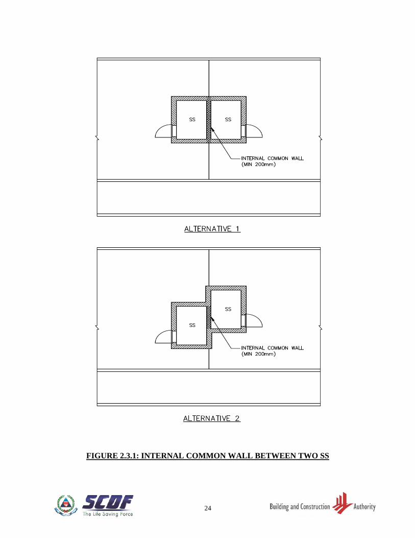
(c) Internal common wall between 2 adjacent SS shall be at least 200mm thick. Refer to
FIGURE 2.3.1.
(d) The minimum internal common wall thickness between SS and enclosed NS shall be
200mm. The minimum internal common wall thickness between SS and non-enclosed
NS shall be 300mm. Refer to FIGURE 2.12.2(i).
(e) For internal SS and S/C SS length more than 8000mm, an additional 25mm thickness
shall be provided to the affected SS wall. Refer to FIGURE 2.2.1(a) and 2.2.1(b).
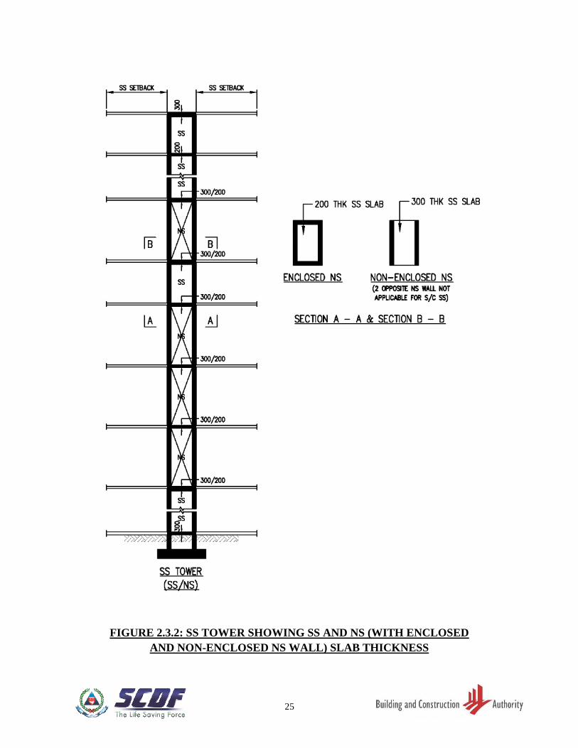
2.3.2 Slab Thickness of SS and Enclosed NS
The minimum dimensions of members forming part of the SS tower shall be as follows:
(a) Ceiling slab of top-most SS or S/C SS or scissor S/C SS – 300mm. Refer to FIGURE
2.3.2.
(b) Slab between two SS or S/C SS or scissor S/C SS – 200mm. Refer to FIGURE 2.3.2.
(c) Floor slab of bottom-most SS/NS in contact with soil – 300mm. Refer to FIGURE
2.3.2.
(d) Slab between SS or S/C SS and enclosed NS - 200mm - Refer to FIGURE 2.3.2.
5
2.3.3 Slab Thickness of SS and Non-Enclosed NS
(a) Floor slab of bottom-most SS that is directly supported by non-enclosed NS or NS
wall - 300mm. Refer to FIGURE 2.3.2.
(b) Ceiling slab of SS which is below non-enclosed NS or NS wall - 300mm.
(c) Slab between two non-enclosed NS - 300mm.
2.4 LOCATION OF SS
2.4.1 SS Position
(a) A SS has to be positioned such that the setback distance of each SS wall shall be as
large as practicable and shall not be less than the minimum specified setback distance.
Setback distance is provided by horizontal RC slab/ trellis at the SS ceiling level or
above.
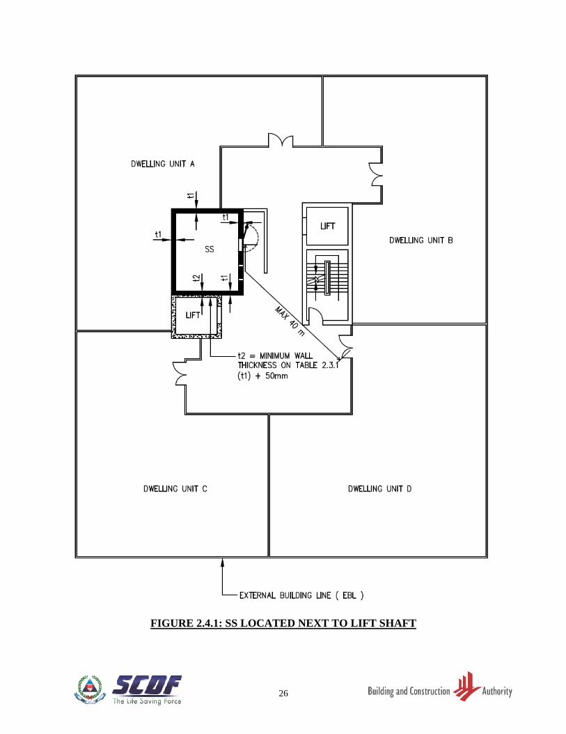
(b) Each of the dwelling units served by the SS shall have at least one exit door at the
same storey as the SS. The travel distance between the SS door and the exit door (at
the same storey as the SS) of any dwelling unit served by the SS shall not exceed 40
metres. Refer to FIGURE. 2.4.1.
2.4.2 SS Tower
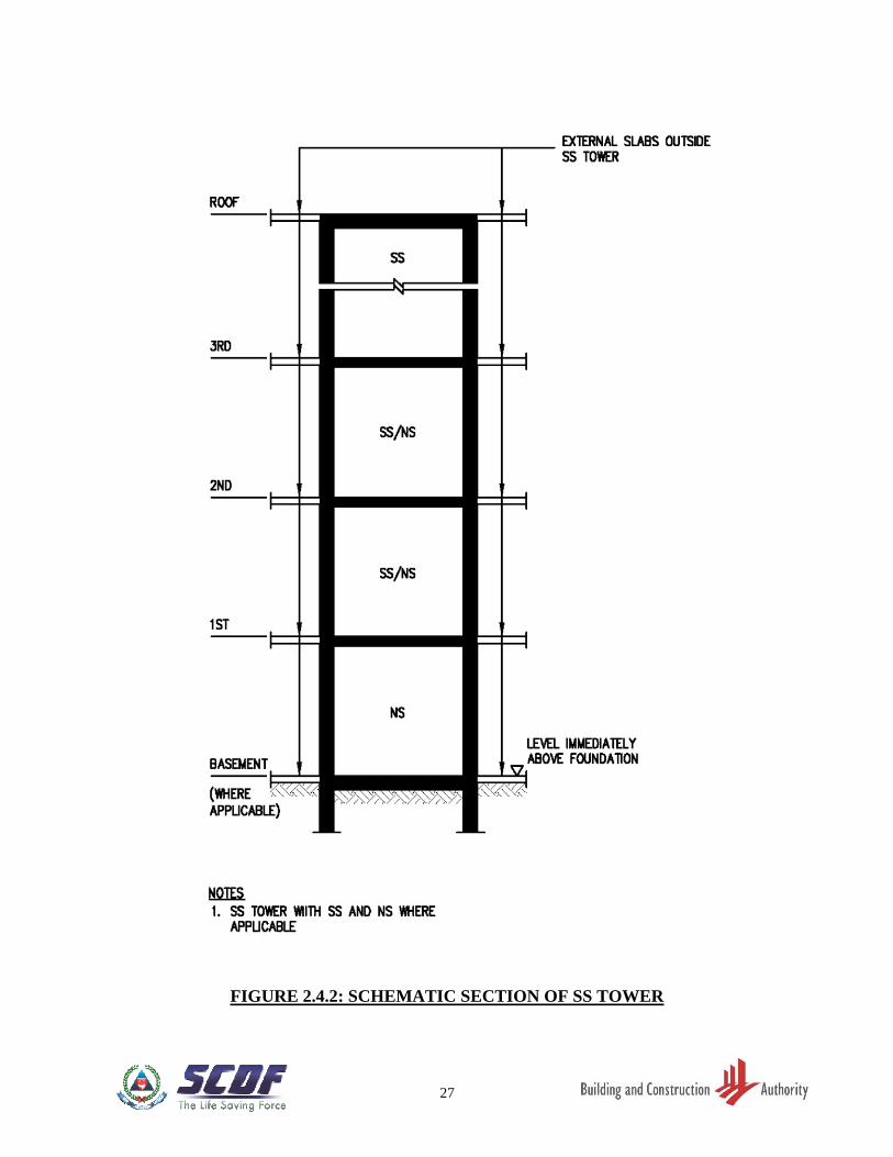
(a) In a building of more than one-storey, the SS (or NS, where applicable) on every storey
shall be located one on top of the other to form a vertical tower with its walls founded
directly to the foundation. Refer to FIGURE 2.4.2.
(b) The space within the NS of the SS tower is not intended for protection of occupants
during war emergency.
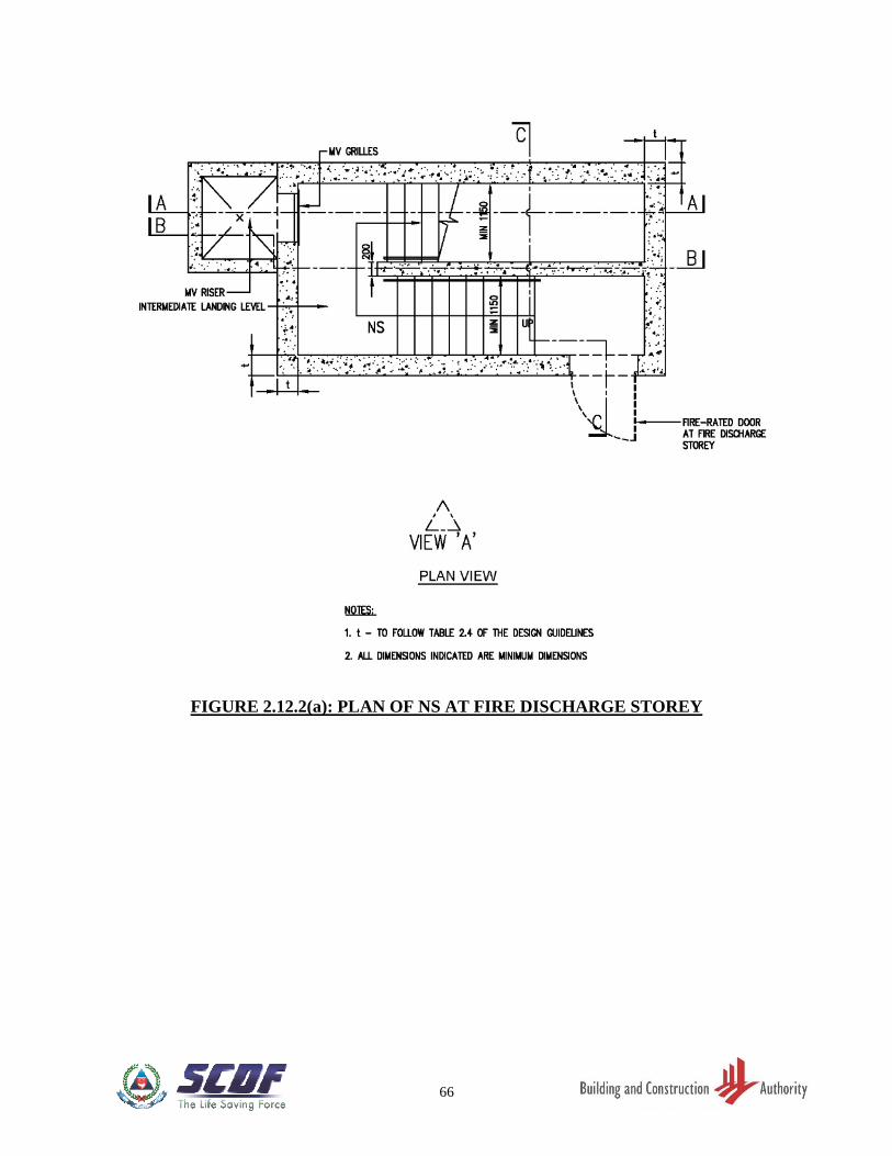
(c) In the case of S/C SS or scissor S/C SS, the SS and NS wall shall be continuous to
foundation, except where there are fire discharge openings at fire discharge levels. The
fire discharge openings shall be located such that all corners of the S/C SS walls are
continuous to foundation
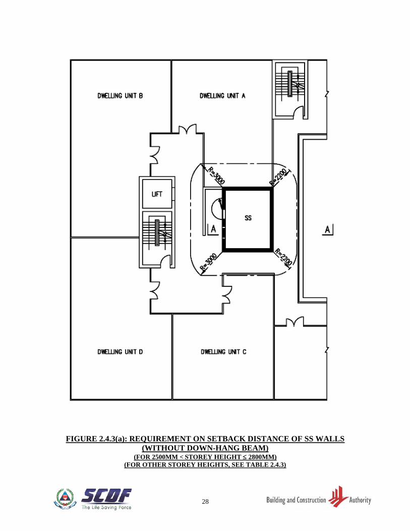
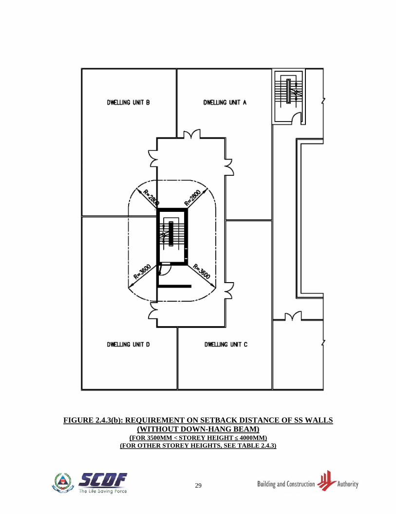
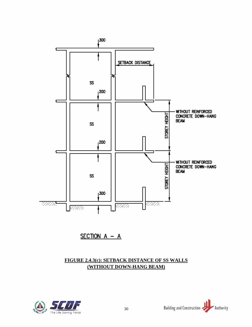
2.4.3 Setback Distances of SS Walls (without Reinforced Concrete Down-hang Beams)
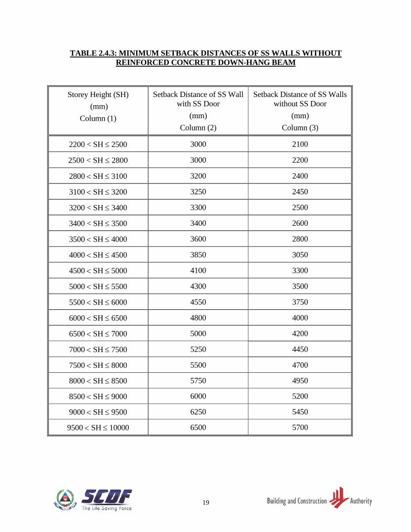
(a) The SS walls shall be located at minimum setback distances as shown in FIGURE
2.4.3(a) to 2.4.3(c) and shall comply with TABLE 2.4.3.
(b) For SS wall (with door), the setback distance requirement shall be read in conjunction
with Clause 2.5.4.
6
(c) Where the storey height of a SS on the first storey is up to 3.6m and is greater than the
storey heights of other SS above it, the minimum setback distances of the SS on the
first storey may be the same as the setback distances of the SS above it.
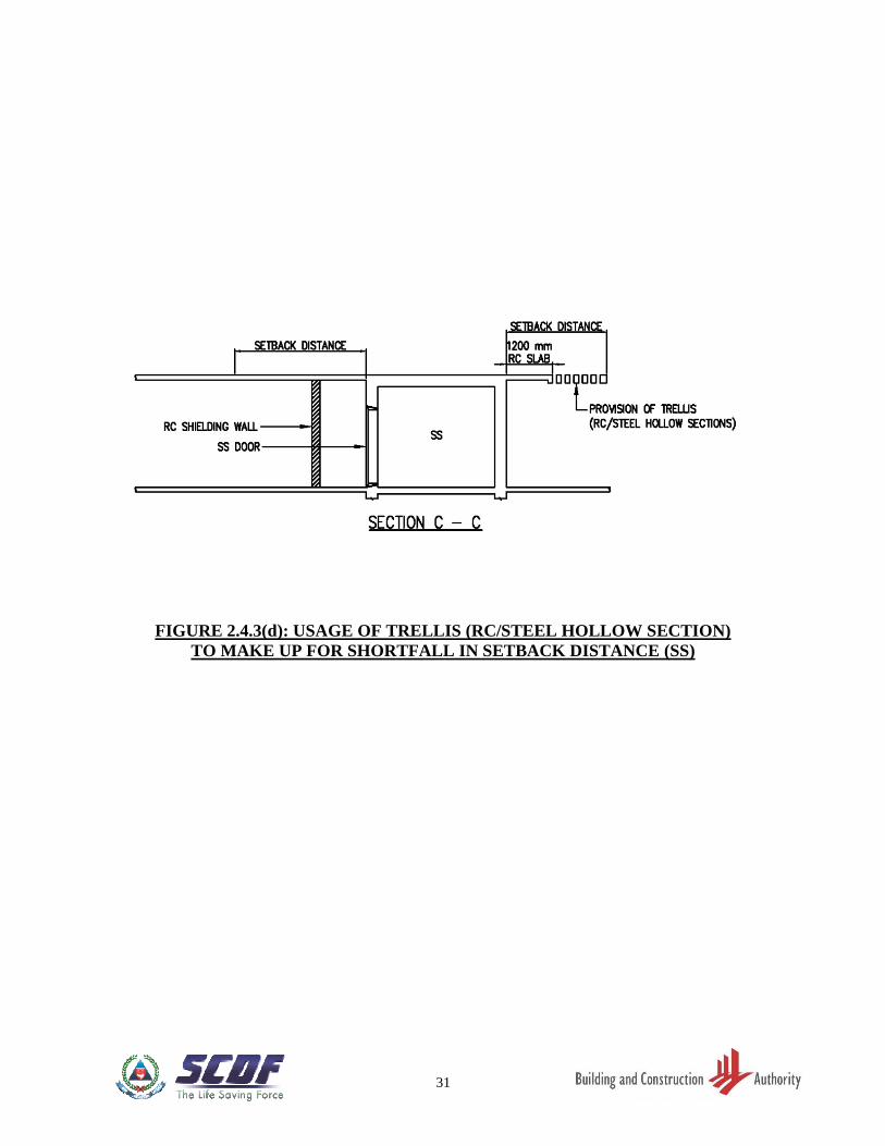
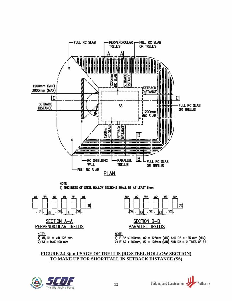
(d) For SS walls (where the SS door is not located), trellis constructed of RC or steel
hollow section may be used to make up for the shortfall in setback distance. However,
a minimum 1200mm RC ceiling slab from the SS wall shall be provided. Refer to
FIGURE 2.4.3(d).
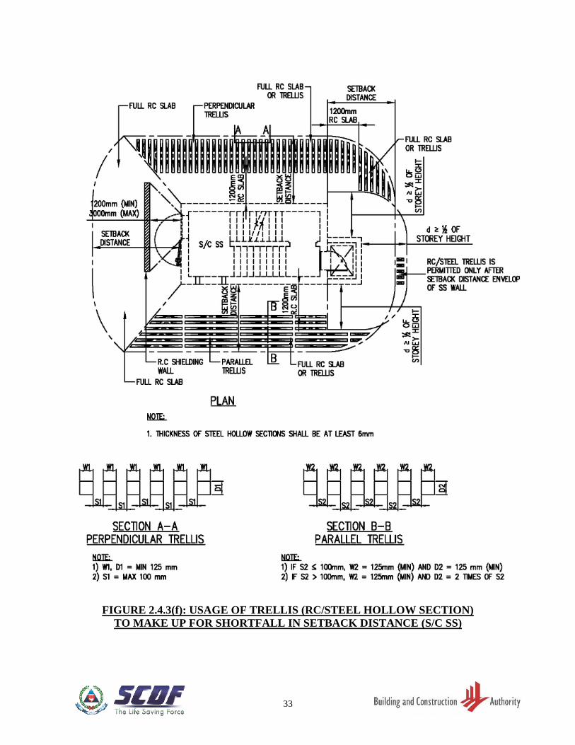
(e) A perpendicular or parallel trellis arrangement, or a combination of both, with respect
to the SS wall concerned, shall comply with the geometrical configuration as shown
in FIGURE 2.4.3(e) and 2.4.3(f).
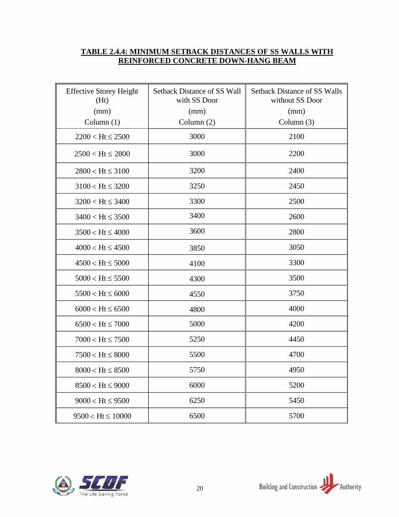
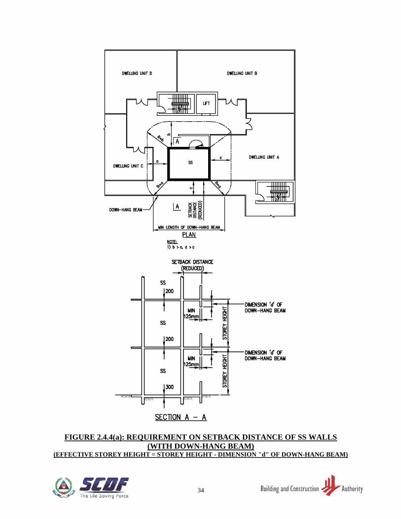
2.4.4 Setback Distances of SS Walls (with Reinforced Concrete Down-hang Beams)
(a) Where RC down-hang beams are provided within setback and more than 1200mm
away from the SS wall, the minimum setback distance of these SS walls can be
reduced based on the effective storey height and in accordance with TABLE 2.4.4.
The effective storey height is determined by the storey height less the dimension
"d" of the RC down-hang beam. Refer to FIGURE 2.4.4(a) and 2.4.4(b).
(b) For SS wall (with door), the setback distance requirement shall be read in conjunction
with Clause 2.5.4.
(c) Clause 2.4.4 shall apply only if the width of the reinforced concrete down-hang beam
is at least 125mm.
(d) Where the storey height of a SS on the first storey is up to 3.6m and is greater than the
storey height of the SS directly above it, the minimum setback distances of the SS on
the 1st storey shall be at least the same as the setback distances of the SS above it.
Where a RC down-hang beam is provided at the 2nd storey ceiling slab, the same
down-hang beam shall be provided at the 1st storey ceiling slab.
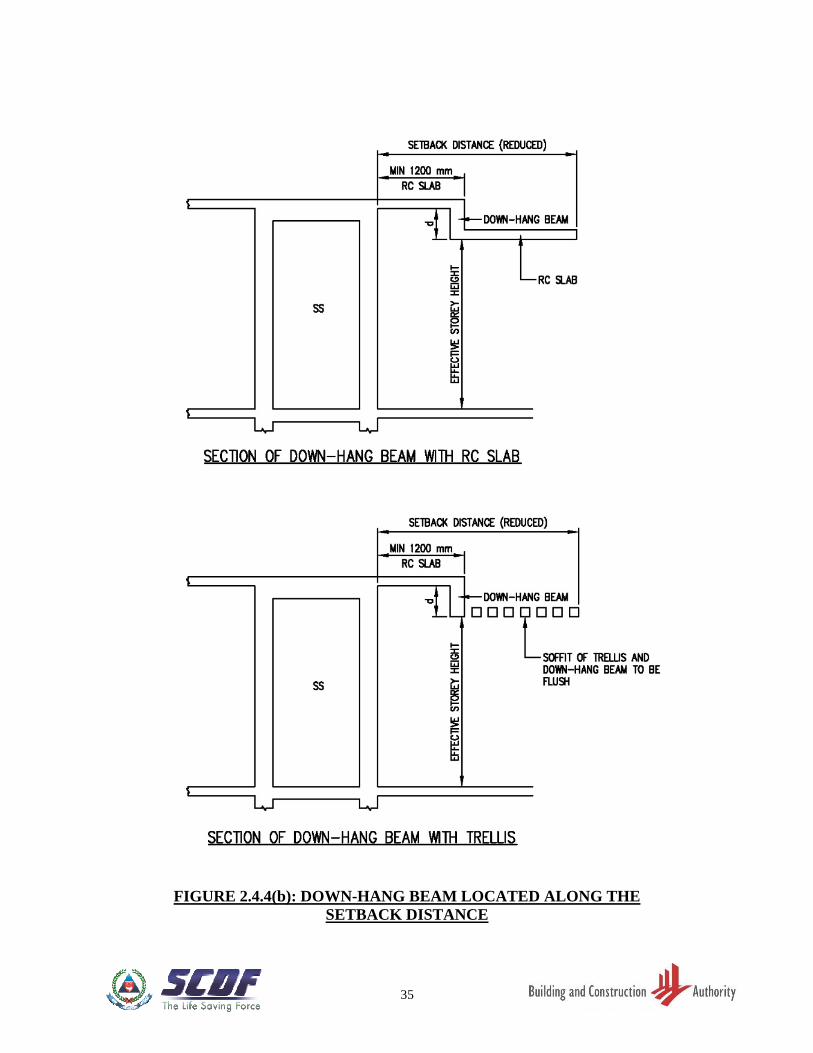
(e) For SS walls (where the SS door is not located), RC ledge or trellis constructed of RC
or steel hollow section may be used to make up for the shortfall in setback distance.
However, a minimum 1200mm RC ceiling slab from the SS wall shall be provided as
shown in FIGURE 2.4.4(b).
(f) A perpendicular or parallel trellis arrangement, or a combination of both, with respect
to the SS wall concerned, shall comply with the geometrical configuration as shown
in FIGURE 2.4.3(e) and 2.4.3(f).
7
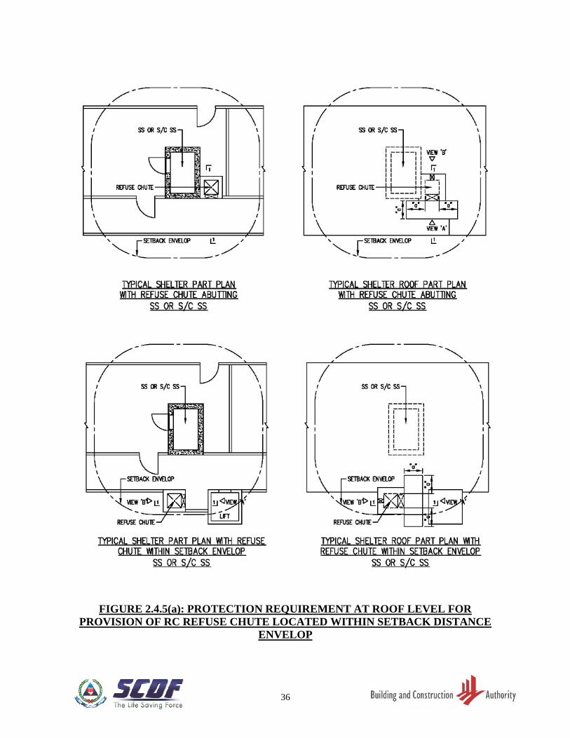
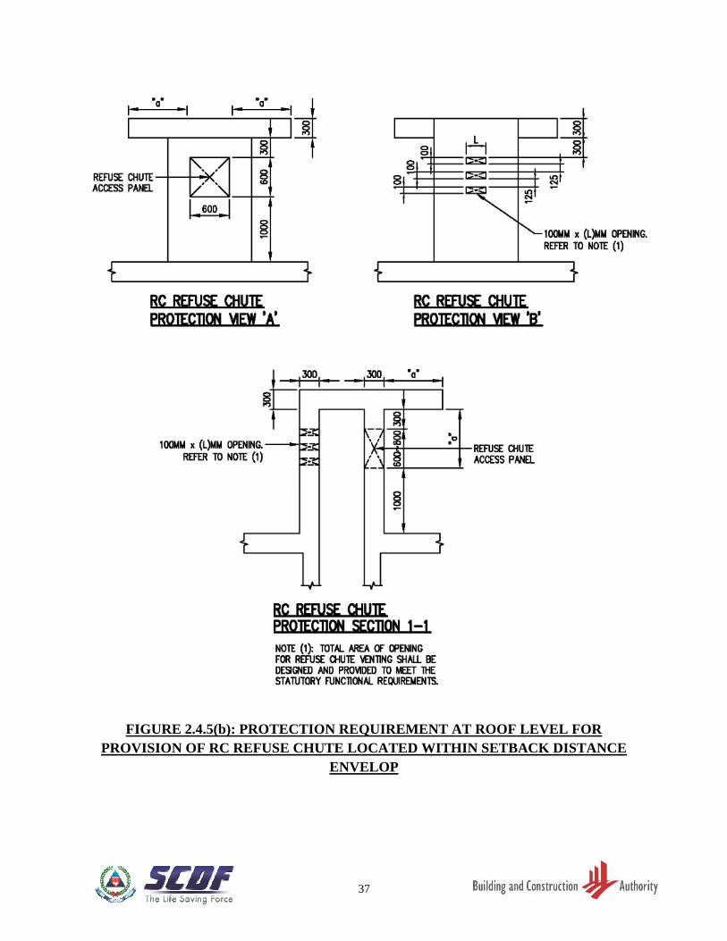
2.4.5 RC Lift Core or/ and RC Refuse Chute or/ and Service Risers, within Setback
Distances of SS Walls
(a) RC lift core can be located within the setback distance of SS, S/C SS or scissor S/C
SS walls. An additional 50mm thickness shall be provided to the SS, S/C SS or scissor
S/C SS wall abutting the RC lift core as shown in FIGURE 2.4.1.
(b) RC refuse chute are allowed within the setback distance envelope of the SS wall
provided that the design of the RC refuse chute walls and ventilated openings at the
roof level comply with the details as shown in FIGURE 2.4.5(a) and 2.4.5(b).
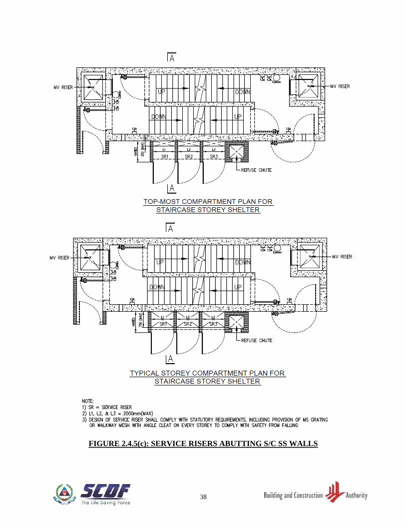
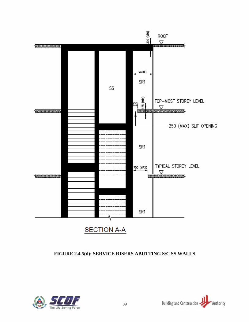
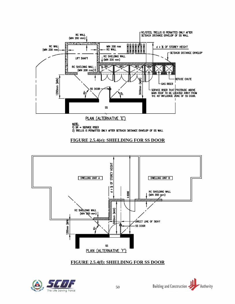
(c) Service risers are allowed within the setback distance envelope of the SS wall (with
or without door). The design shall comply with the details as shown in FIGURE
2.4.5(c) and 2.4.5(d), provided that the ceiling slab at the roof level is of reinforced
concrete, and the relevant fire safety requirements for compartmentalisation of the
service risers.
(d) For gas riser and any service risers within the setback distance and protrude above the
main roof, the design shall comply with the requirements as shown in FIGURE
2.4.5(e) to 2.4.5(g)
(e) The gas riser and/or RC refuse chute and any service risers that protrude above the
main roof, designed within the setback distance envelope of the SS wall (with door)
shall be located away from 45o influence zone from SS door. Refer to FIGURE
2.5.4(e).
2.4.6 Voids within SS Setback Distances
Voids can be located within the SS setback distance and shall comply with the following
requirements. Refer to FIGURE 2.4.6.
(a) Void located within 1200mm boundary from SS walls:
(i) The void shall be enclosed by minimum thickness of 150mm RC walls or
200mm block/ brick walls.
(ii) The maximum length and area of each void shall be 1000mm and 0.7m2
respectively.
(iii) There shall be at least a 150mm RC wall or 200mm block/ brick wall between
adjoining voids.
(iv) RC slab of at least 300mm thick shall be provided at the roof of the void.
(v) RC slab of at least 125mm thick shall be provided to cover the void at the top-
most storey level immediately below the roof slab.
8
(b) Void located beyond 1200mm boundary from SS walls:
(i) The voids shall be enclosed by minimum thickness of 150mm RC walls or
200mm block/ brick walls.
(ii) The maximum length and area of each void shall be 1000mm and 0.7m2
respectively.
(iii) There shall be at least a 150mm RC wall or 200mm block/ brick wall between
adjoining voids.
(iv) RC slab of at least 125mm thick shall be provided at the roof of the void.
2.5 SS DOOR
2.5.1 Opening Dimensions
The opening dimensions of SS door shall be:
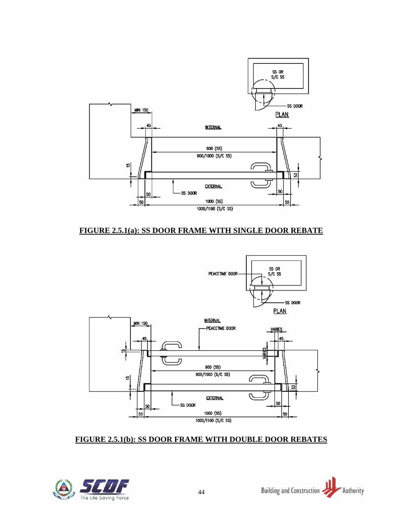
(a) For SS – 900(W) mm x 1900(H) mm
(b) For S/C SS and scissor S/C SS
(i) For entrance SS door, the dimension shall be 900(W) mm or 1000(W) mm x
2055(H) mm.
(ii) For internal SS door at mid-landing or main landing in the staircase, the
dimension shall be 1000(W) mm x 2055(H) mm.
(c) SS door frame that is cast together with the SS wall shall have single or double door
rebate. Refer to FIGURE 2.5.1(a) and 2.5.1(b).
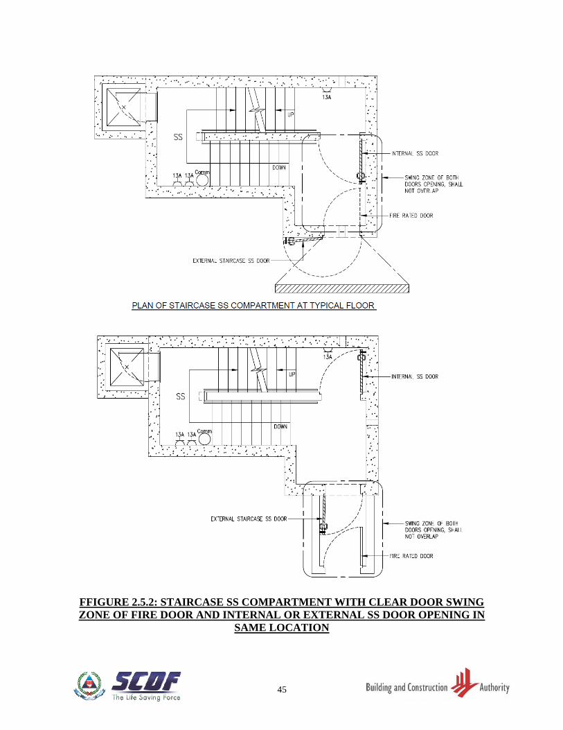
2.5.2 Location
The SS door shall be located in a SS wall with a minimum setback distance of 3000mm and
shall not swing in a direction that will clash with the swing path of another peacetime door.
Refer to FIGURE 2.5.2.
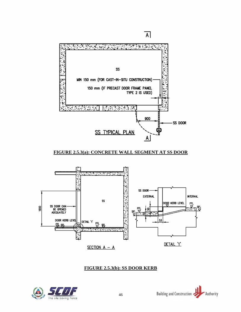
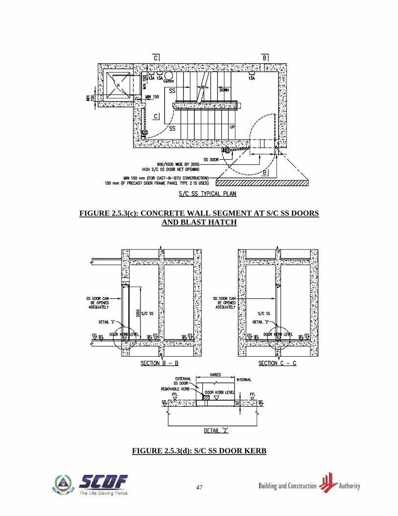
2.5.3 Door Frame
(a) There shall be a minimum 150mm reinforced concrete wall segment next to vertical
edge of SS or S/C SS door frame. Refer to FIGURE 2.5.3(a) and 2.5.3(c).
(b) For pre-cast door frame panel of Type 1, the reinforced concrete next to two vertical
edges of the SS door frame shall be 300mm each. Refer to FIGURE 3.5.5(a).
9
(c) For pre-cast door frame panel of Type 2, the reinforced concrete next to vertical edges
of the SS door frame shall be 300mm on one side, and 150mm plus the SS wall
thickness on the other side. Refer to FIGURE 3.5.5(f).
(d) For pre-cast door frame panel of Type 3, the reinforced concrete panel with full length
or width of SS wall must be properly connected to the in-situ SS walls and slabs. Refer
to FIGURE 3.5.5(k).
(e) The SS or S/C SS door frame must be positioned such that its door is above FFL and
can be opened at least 90°. Refer to FIGURE 2.5.3(b) and 2.5.3(d).
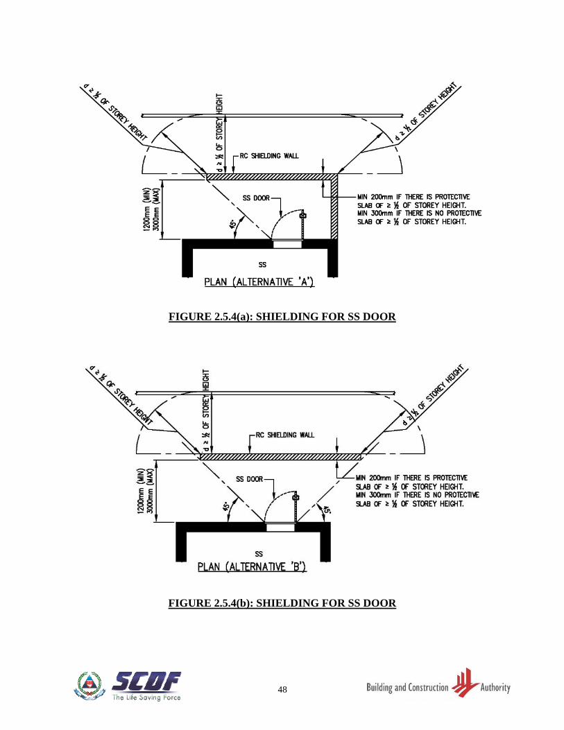
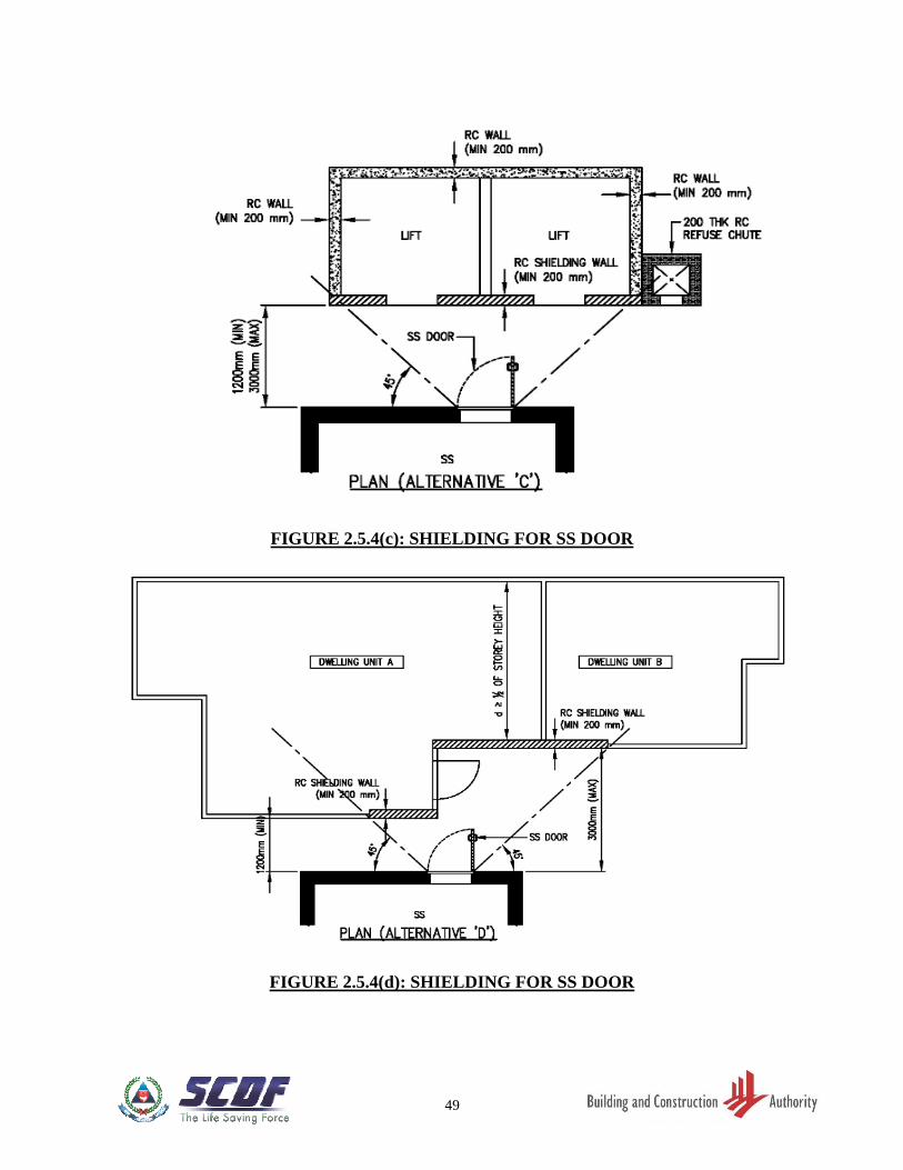
2.5.4 Shielding Wall
(a) A full-height reinforced concrete shielding wall, with a minimum thickness of 200mm
(with protective slab extended by at least ½ of storey height from the shielding wall)
or 300mm (if the protective slab is extended by less than ½ of storey height), has to
be provided in front of the entrance SS door.
(b) The shielding wall to the SS door can be positioned and arranged in the following
manner:
(i) A shielding wall has to be positioned such that it is at least 1200mm but not
more than 3000mm from the SS door and is within influence zone of 45-degree
from the SS door. Refer to FIGURE 2.5.4(a) to 2.5.4(f). The shielding wall
forming part of the dwelling unit’s wall shall be clearly indicated on plans.
(ii) The shielding wall shall be protected by floor slab or trellis of at least half the
storey height measured from the shielding wall. Refer to FIGURE 2.5.4(a),
2.5.4(b), 2.5.4(d) to 2.5.4(f).
(iii) Where the lift shaft is facing the SS door, the RC wall of the shaft can be used
as a shielding wall provided its thickness is at least 200mm. Refer to FIGURE
2.5.4(c). For such case, the surrounding lift shaft wall and roof slab of lift
motor room shall be reinforced concrete.
(iv) For service risers located within influence zone, the RC walls of the risers can
be used as shielding wall provided its thickness is at least 200mm. Refer to
FIGURE 2.5.4(e).
(v) Where the shielding wall located within influence zone is discontinuous, the
opening in this wall shall not be in the line of sight of SS door. In the case of
the opening not in the line of sight of SS door but facing the SS wall, there
shall be RC slabs with a minimum distance of 8000mm provided from the SS
wall. Refer to FIGURE 2.5.4(d) and 2.5.4(f).
10
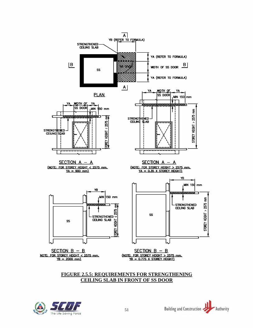
2.5.5 Strengthened Ceiling Slab outside SS Door
The minimum thickness of the reinforced concrete ceiling slab immediately outside the SS
door shall be 150mm and structurally connected to SS tower. The dimensions of this
strengthened portion shall be as shown in FIGURE 2.5.5.
2.6 FIXTURES IN SS
2.6.1 General
(a) The following electrical and communication fixtures (Refer to FIGURE 2.6.1(a),
2.6.1(b), 2.12.1(f) and 2.12.2(j)) in steel or PVC conduit system shall be provided
inside each SS or S/C SS compartment to provide adequate stay-in and/ or
communication facilities:
(i) 13A switch socket outlets;
(ii) Switch and lighting points;
(iii) Communication line for telephony outlet.
(b) The electrical and communication fixtures shall be designed and installed in
accordance with the relevant local Codes of Practice and statutory requirements for
peacetime usage.
(c) The communication line for telephony outlet in each SS or S/C SS compartment
shall have its own independent line where it is connected from the fibre termination
point in the compartment to the fibre interface point in the relevant riser of the
development.
(d) A maximum of ten numbers of 25mm diameter service conduits for electrical and
communication cables serving the SS are allowed. Refer to Clause 3.6.1 for
embedment details.
(e) The electrical and communication fixtures shall be located away from the rescue
hatch openings in the SS. Refer to FIGURE 2.6.1(a).
(f) The mounting height of the lighting switch and other electrical and communication
fixture shall comply with the relevant statutory board requirements for peacetime use.
Refer to FIGURE 2.6.1(b).
(g) Other fixtures, such as cabinets and shelves, which are required for peacetime use
in SS, are allowed provided they are easily dismantled and removed.
11
2.6.2 Switch Socket Outlets
(a) For SS
Three (3) 13A switch socket outlets shall be provided inside each SS. Two switch
socket outlets shall be in the vicinity of the communication for telephony outlet located
away from the SS door. The third switch socket outlet shall be located near the
ventilation sleeve opening. Refer to FIGURE 2.6.1(a).
(b) For S/C SS
Three (3) 13A switch socket outlets shall be provided inside each S/C SS
compartment. At least one switch socket outlet shall be provided at the main landing.
The other two switch socket outlets shall be provided at the intermediate landing
together with the communication for telephony outlet. Refer to FIGURE 2.12.1(f) for
details.
(c) For Scissor S/C SS
Three (3) 13A switch socket outlets shall be provided inside each scissor S/C SS
compartment. At least one switch socket outlet shall be provided at the main landing
at the upper floor of the SS compartment. The other two switch socket outlets shall be
provided at the main landing, together with the communication for telephony outlet at
the lower floor of the SS compartment. Refer to FIGURE 2.12.2(j) for details.
2.6.3 Light Fitting
Light fittings shall be mounted only on the soffit of SS ceiling with screws, using non-metallic
inserts. Wall mounted luminaries are not permitted.
2.6.4 Cable Entries and Openings
All cable entries shall be fully and properly sealed for air-tightness as stipulated in Clause
3.6.1.
2.7 NS IN SS TOWER
2.7.1 Aggregate Wall Height of NS
(a) Several NS can be stacked one on top of the other within an SS tower, without the
need for NS floor slab to be connected to external floor slab, provided that the
aggregate wall height of the NS does not exceed 12m. Refer to FIGURE 2.7.1.
(b) Aggregate wall height of NS refers to the sum of the height(s) of NS between two
levels of the SS tower where the full external perimeter of the SS tower at those levels
are structurally connected by floor slabs or tie beams to the structural frame of the
12
building. Where tie beams are used, they shall be designed with at least equivalent
stiffness to the floor slabs.
2.7.2 Shielded and Unshielded NS Walls
The relevant architectural technical requirements of the shielded or unshielded NS Walls as
stipulated in Clause 3.3.3 & 3.3.4 shall be complied with.
2.8 FINISHES IN SS
Finishes within a SS shall comply with the following:
(a) The walls and the ceiling slab shall be cast with a smooth concrete finish.
(b) The walls and ceiling slab may be finished with a skim coat of not thicker than 2mm.
(c) No plastering or tiling shall be permitted on the walls and ceiling slab.
(d) Floor tiles or floor finishes, which are laid on wet cement mortar, are permitted.
(e) Skirting tiles laid on wet cement mortar are permitted up to a maximum 100mm high
above the FFL.
2.9 EXIT STAIRCASE
(a) Where there is only one exit staircase or scissors-staircase serving the dwelling
units, the minimum waist of exit staircase and the thickness of the intermediate
landing slab shall be 150mm. The staircase shall be constructed of reinforced
concrete.
(b) If the exit staircase or scissors-staircase are designed as the S/C SS, the waist of the
staircase shall be minimum 200mm.
2.10 DOOR RECESS
A door recess on SS or S/C SS external wall, to accommodate the protrusion of the door
handle when the SS door is fully open, shall be provided. Refer to FIGURE 2.10.
(a) The dimensions shall not be larger than 160mm (length) x 80mm (height) x 40mm
(depth) for SS or S/C SS wall of minimum 300mm thickness and shall accommodate
the door handle adequately.
(b) The clear spacing between the SS door handle recess and the external socket outlet/
other fixtures or internal fixtures shall be at least 300mm apart.
13
2.11 DESIGN REQUIREMENTS OF SS
2.11.1 Rescue Hatch
(a) A rescue hatch shall be provided on the floor and ceiling on every SS in a SS tower,
except that the bottom-most SS shall not have a rescue hatch in its floor and the top-
most SS shall not have a rescue hatch in its ceiling. The hatch shall be made of airtight
sealed galvanised steel and shall comply with relevant fire safety requirements for
compartmentalisation of the SS*. (* QP is advised to look into the fire safety requirements of their designs for compartmentalisation of
the SS).
(b) The rescue hatch opening in an SS shall be positioned adjacent to the SS walls with
minimum dimensions as shown in FIGURE 2.11.1(a). The vertical centreline of the
rescue hatch opening in the ceiling shall be offset from the centreline of the rescue
hatch in the floor of the same SS by at least 1400mm. Refer to FIGURE 2.11.1(b).
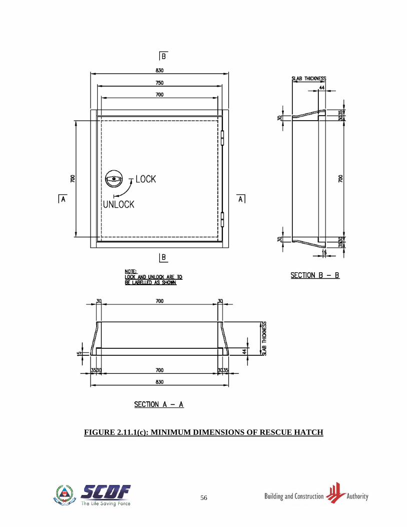
(c) The clear opening of the rescue hatch shall be 700mm x 700mm. The dimensions of
the rescue hatch are as shown in FIGURE 2.11.1(c).
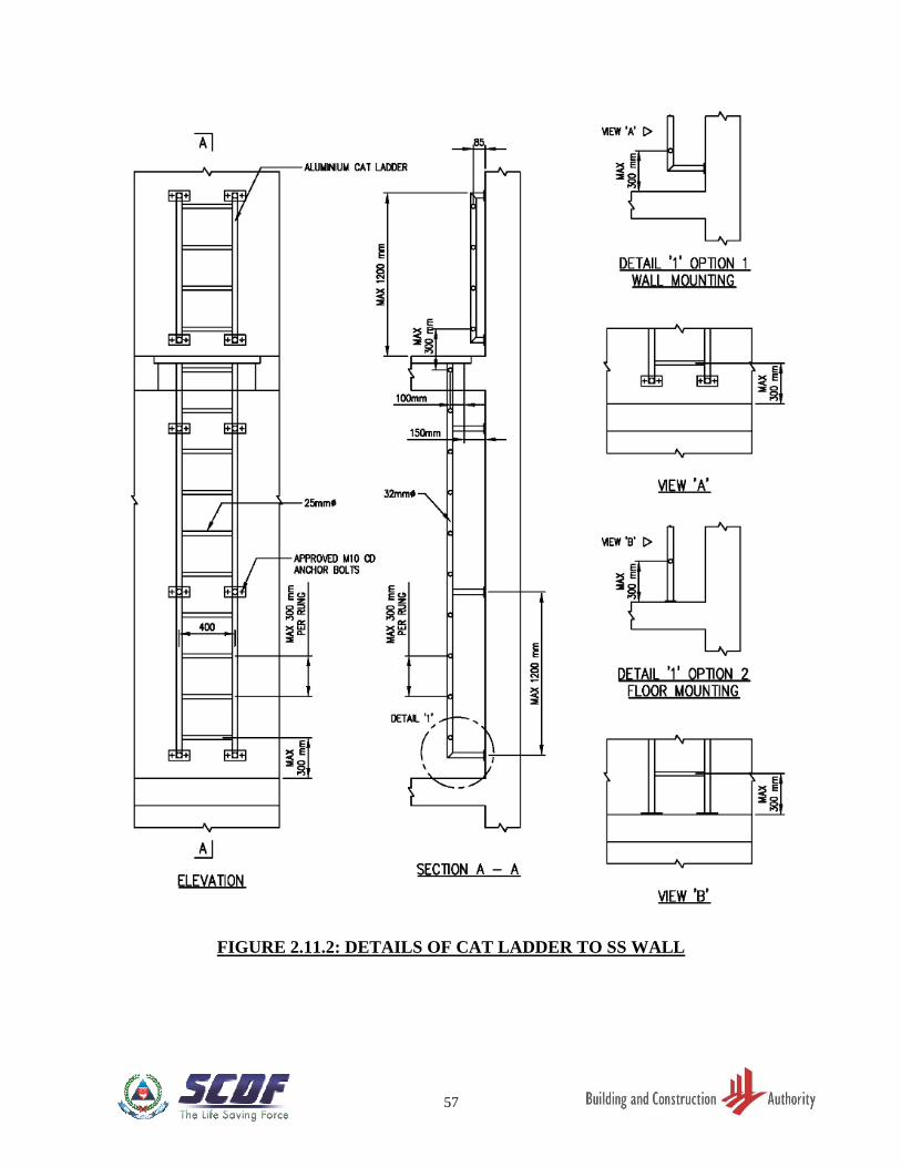
2.11.2 Cat-Ladder
Cat-ladder shall be provided for access through rescue hatch opening. The cat-ladder shall be
made of either stainless steel or aluminium or equivalent. The mounting connections of cat-
ladder to the SS wall shall be designed to withstand shock loads of at least 12.5g in all
directions, where g is the gravitational acceleration, details and dimensions as shown in
FIGURE 2.11.2.
2.12 DESIGN REQUIREMENTS OF S/C SS AND SCISSOR S/C SS
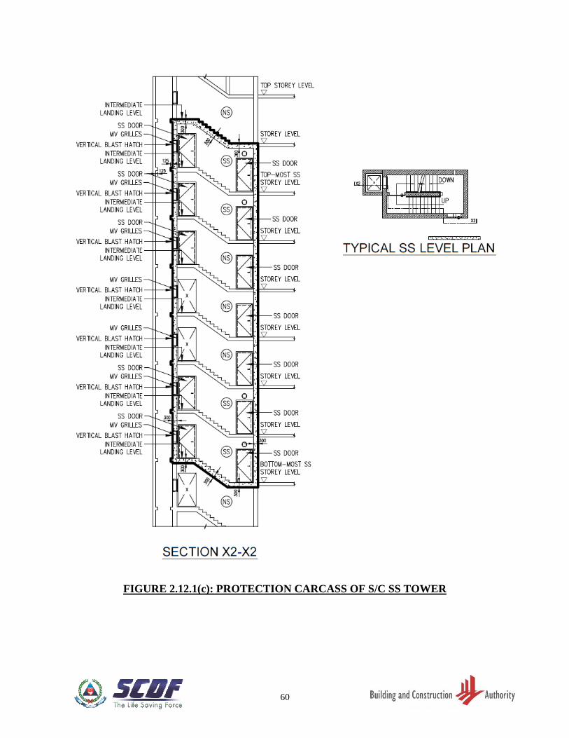
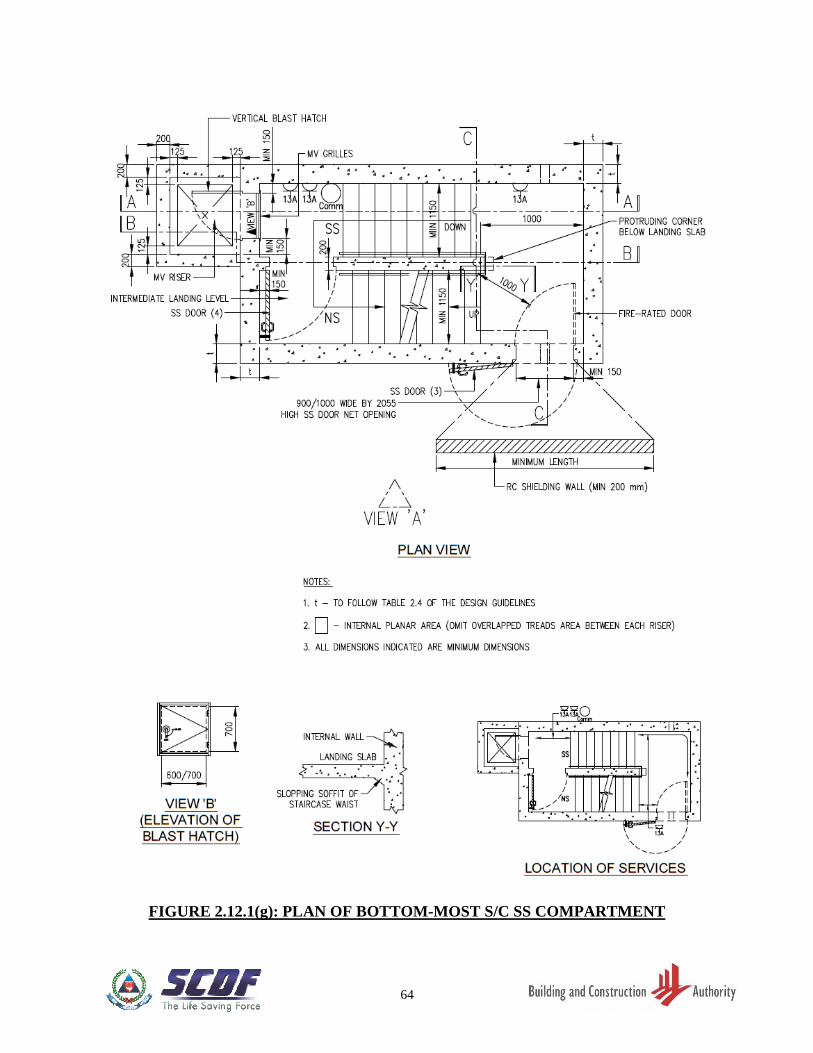
2.12.1 General
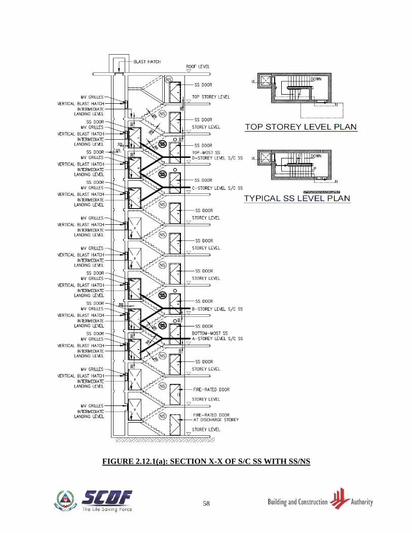
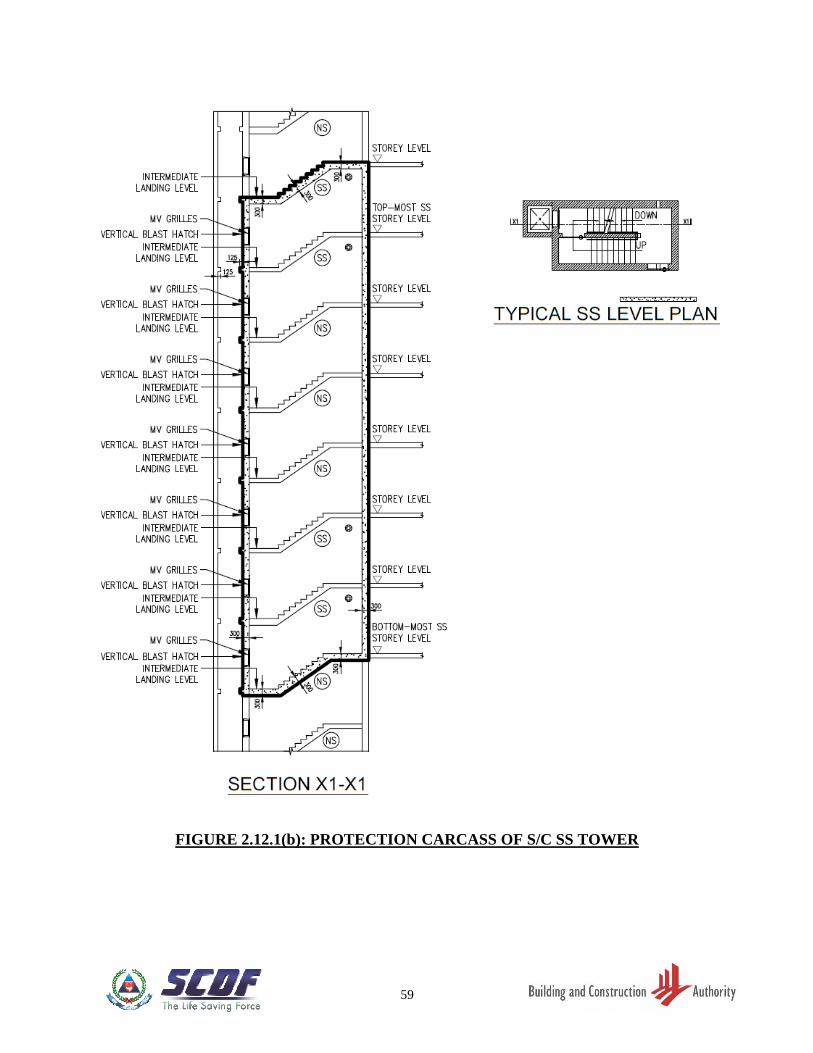
(a) The protection carcass shall be formed by external SS wall, floor slab of the bottom-
most shelter compartment and the ceiling slab of the top-most shelter compartment.
FIGURE 2.12.1(a) to 2.12.1(c).
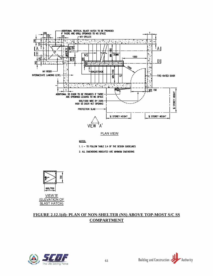
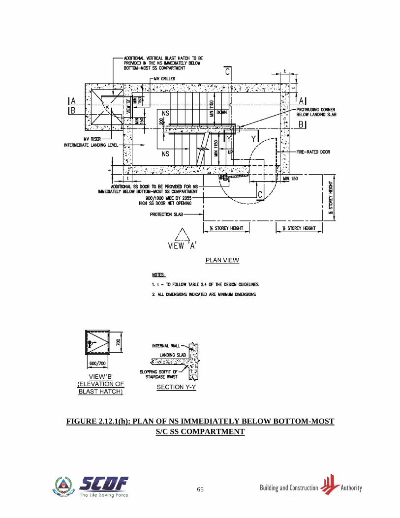
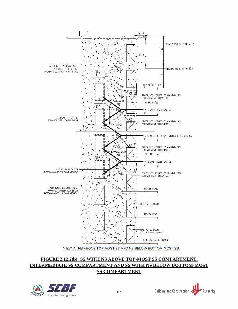
(b) In the case of NS interspersed within the S/C SS or scissor S/C SS tower, SS doors
and vertical blast hatches shall be provided to the opening leadings to the following
NS. Refer to Figure 2.12.1(d) to 2.12.1(h).
(i) One NS immediately below the bottom-most SS.
(ii) Two NS immediately above the top-most SS.
(iii) NS between SS compartments.
14
(c) All SS doors are to be kept opened permanently during peacetime. As such, a door
holder shall be provided to hold the door in open position. Refer to FIGURE
2.12.2(l).
(d) S/C SS and scissor S/C SS have to be mechanically ventilated for peacetime purpose.
The number of mechanical ventilation (MV) openings is based on the peacetime MV
design. Where there are MV openings, grille openings for entry of ventilating air via
mechanical ventilation (MV) riser are permitted. Refer to Figure 2.12.2(c).
Typically, for a scissor S/C SS, the MV openings are at alternate floors of each SS
tower as shown in FIGURE 2.12.2(j) and 2.12.2(k).
(e) No other openings shall be permitted in each S/C SS compartment except for the two
ventilation sleeves, which are placed in closed position, and the required MV
opening.
2.12.2 S/C SS Doors at Shelter Entrance
(a) At every storey, one SS door with removable door kerb, is to be provided at the
shelter entrance and shall be kept in the open position during peacetime. Refer to
FIGURE 2.12.2(b), 2.12.2(d) to 2.12.2(k). A door holder shall be provided to hold
the internal SS door in open position. Refer to FIGURE 2.12.2(l). As this SS door
swing against the direction of exit travel, it shall be not doubled up as the peacetime
fire-rated door.
(b) Where the staircase leads to the roof level, an external SS door swinging outwards
from the staircase, has to be provided at the staircase entrance. This external SS door
shall also be permanently kept open during peacetime and shall be suitably protected
from the weather if it is exposed to external space.
2.12.3 Internal S/C SS Wall and SS Door
(a) Inside the S/C SS, there has to be a continuous reinforced concrete internal wall of
minimum 200mm thickness running through the full height of the S/C SS tower. At
every storey, one internal SS door swinging in the direction of exit travel, with
removable door kerb, is to be provided either at the staircase entrance landing or at
the intermediate landing. Refer to FIGURE 2.12.1(f), 2.12.2(b), 2.12.2(j) and
2.12.2(k). The SS door clear opening dimensions shall be:
(i) Door opening width - 1000mm.
(ii) Door opening height - 2055mm.
(b) This SS door is to be kept permanently open during peacetime. A door holder shall
be provided to hold the internal SS door in open position. Refer to FIGURE 2.12.2(l).
15
(c) The RC wall and the internal SS door (when placed in closed position) serve to
compartmentalise the staircase shaft into a series of staircase SS i.e. one SS
compartment for each storey.
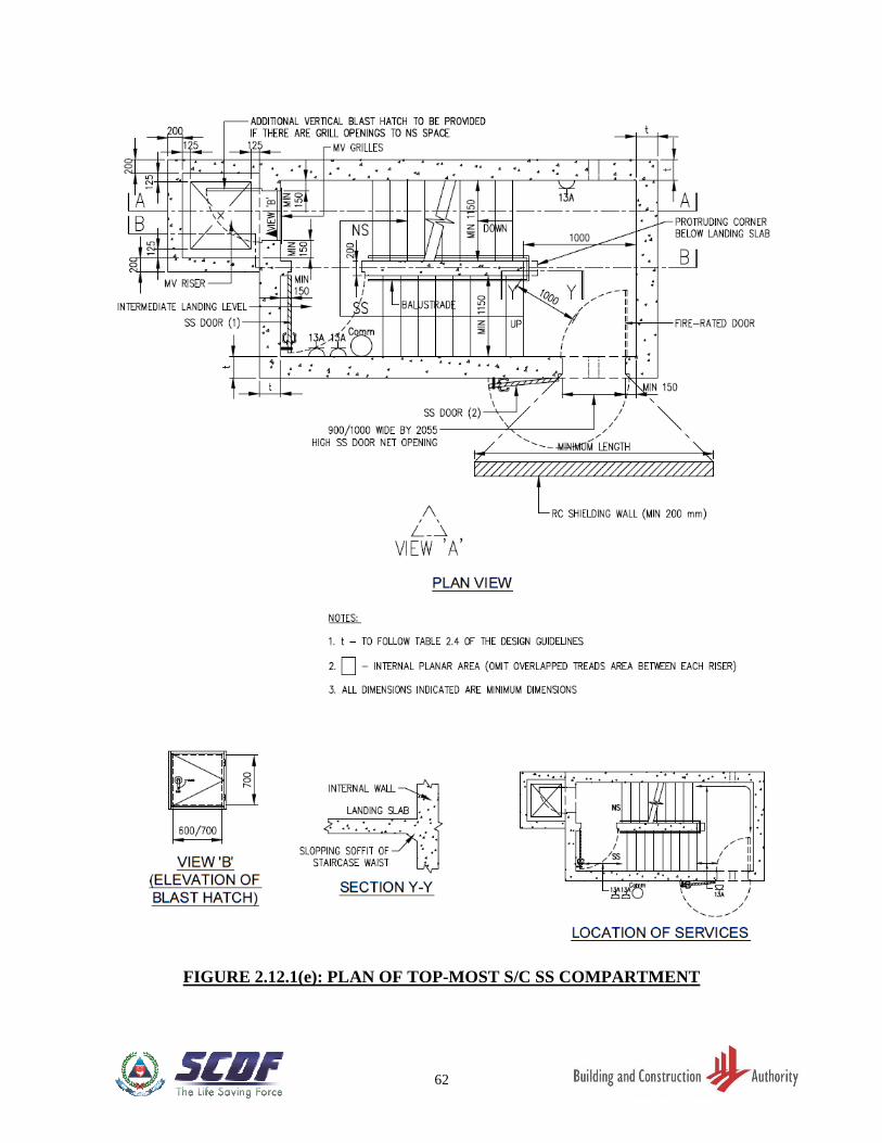
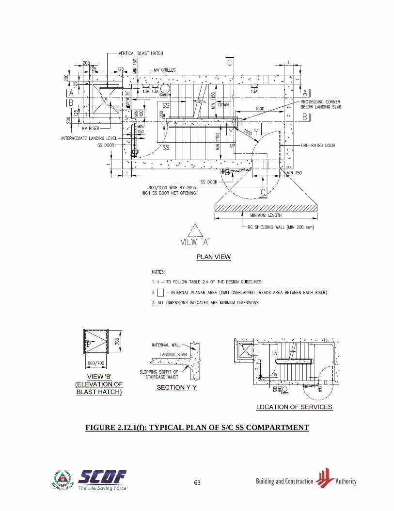
2.12.4 Shelter Compartment
(a) S/C SS comprises one SS compartment each storey. Each shelter compartment shall
be made up of one entrance SS door and 2 internal SS doors, i.e. one at each
intermediate landing or main landing. Refer to FIGURE 2.12.1(f) and 2.12.2(b). For
fire discharge level, refer to FIGURE 2.12.2(f) to 2.12.2(h).
(b) Scissor S/C SS comprises two SS at each storey. Each SS compartment shall be made
up of one entrance SS door and 2 internal SS doors. Refer to FIGURE 2.12.2(j) and
2.12.2(k). Signage shall be provided adjacent to each SS door entrance showing the
designated dwelling units assigned to each shelter compartment.
(c) The slopping soffit of the staircase waist shall be continuous to meet the staircase.
This shall include the part of slopping soffit projected from the 200mm thick internal
wall as shown in FIGURE 2.12.1(f) and 2.12.2(d).
2.12.5 Blast Hatch at MV Opening
(a) There shall be a minimum 150mm reinforced concrete wall segment next to vertical
edge of the blast hatch. Refer to FIGURE 2.5.3(c).
(b) As the S/C SS and scissor S/C SS are to be mechanically ventilated, there would be
vertical grille openings in S/C SS or scissor S/C SS wall. Where there are such
openings (subject to the mechanical ventilation design), there shall be vertical blast
hatch at the height of 1000mm-1200mm from the FFL, swung open into the MV
riser, provided at these openings. Refer to FIGURE 2.12.2(c), 2.12.2(j) and
2.12.2(k). These openings shall be closed and made airtight by vertical blast hatches
when the S/C SS or scissor S/C SS is converted for use as SS.
(c) The MV walls serve as the shielding walls for the blast hatch and shall be minimum
thickness of 200mm (with RC protective slab extended by at least ½ of storey height
from the shielding wall) or 300mm (if the RC protective slab is extended by less than
½ of storey height). Refer to FIGURE 2.4.3(f).
2.12.6 Blast Hatch at MV Chamber
(a) Horizontal blast hatch shall be provided at the MV chamber at roof level as shown
in FIGURE 2.12.6(a) to 2.12.6(d).
(b) Safety hook shall be provided in the protective wall next to the horizontal blast hatch
opening at roof level as shown in FIGURE 2.12.6(a) to 2.12.6(d).
16
(c) An unobstructed passageway shall be provided to the roof level for the operation and
maintenance of the blast hatch in the MV chamber.
(d) Ceiling light, switch, single power socket outlet and safety steel mess shall be
provided in the MV chamber as shown in FIGURE 2.12.6(a) to 2.12.6(d).
2.12.7 Dimensions and Other Requirements of Blast Hatch
(a) The minimum size of the vertical panel or MV grille for access to open/close the
vertical blast hatch between the MV riser and staircase SS shall be 600/700mm by
700mm. The internal SS door shall be positioned such that it swings away from the
vertical blast hatch opening. Refer to FIGURE 2.12.1(f) and 2.12.2(j).
(b) There shall be reinforced concrete ledge or steel ledge provided around the MV duct
for inspection and maintenance of the vertical blast hatch. Refer to FIGURE
2.12.1(f), 2.12.2(c) and 2.12.2(k).
(c) The details of the nib dimensions for horizontal blast hatch opening at the MV
chamber are as shown in FIGURE 2.12.6(a) to 2.12.6(d).
(d) The net clear opening of the vertical and horizontal blast hatches shall be 600/700mm
x 700mm as shown in FIGURE 2.12.7(a) and 2.12.7(b).
(e) “Unlocking” or “Locking” label or sticker to indicate the unlocking or locking
position at the locking device shall be provided for all blast hatches. Refer to
FIGURE 2.12.7(a) and 2.12.7(b).
2.12.8 Provision of cut-off Sprinkler outside S/C SS and Scissor S/C SS
Where cut-off sprinkler is required to be provided in the fire-protected space for the
compliance to fire safety, the cut-off sprinkler compartment shall be provided outside the
S/C SS. Refer to FIGURE 2.12.8.
17
TABLE 2.2.1: MINIMUM INTERNAL SS FLOOR AREA AND VOLUME
Gross Floor Area (GFA)* of
Dwelling Unit
Nominal Occupancy of
Dwelling Unit
(No. of persons catered for in SS)
GFA 45m2
2
45m2 < GFA 75m2
3
75m2 < GFA 140m2
4
GFA > 140m2
5
* The GFA of the dwelling unit excludes the area of balconies that are open on at least two sides to make the balconies
conducive for sky-rise gardening in accordance with URA guidelines.
Area of Storey Shelter TNO x 0.6m2
Volume of Storey Shelter TNO x 1.8m3
TNO Total Nominal Occupancy of units served by Storey Shelter
18
TABLE 2.3.1: REQUIRED MINIMUM SS AND NS WALL THICKNESS
Storey Height (SH)
(mm)
SS/NS Clear Height (Ht)
(mm)
Setback Distance of
SS Wall
(mm)
Wall Thickness
(mm)
SH < 4000
2400 Ht 3400 6000 300
6000 250
3400 Ht 3900 6000 325
6000 275
4000 < SH < 6000
2400 Ht 3400 7000 300
7000 250
3400 Ht 3900 7000 325
7000 275
6000 < SH < 8000
2400 Ht 3400 8000 300
8000 250
3400 Ht 3900 8000 325
8000 275
8000 < SH < 10000
2400 Ht 3400 9000 300
9000 250
3400 Ht 3900 9000 325
9000 275
19
TABLE 2.4.3: MINIMUM SETBACK DISTANCES OF SS WALLS WITHOUT
REINFORCED CONCRETE DOWN-HANG BEAM
Storey Height (SH)
(mm)
Column (1)
Setback Distance of SS Wall
with SS Door
(mm)
Column (2)
Setback Distance of SS Walls
without SS Door
(mm)
Column (3)
2200 < SH 2500 3000 2100
2500 < SH 2800 3000 2200
2800 SH 3100 3200 2400
3100 SH 3200 3250 2450
3200 < SH 3400 3300 2500
3400 < SH 3500 3400 2600
3500 SH 4000 3600 2800
4000 SH 4500 3850 3050
4500 SH 5000 4100 3300
5000 SH 5500 4300 3500
5500 SH 6000 4550 3750
6000 SH 6500 4800 4000
6500 SH 7000 5000 4200
7000 SH 7500 5250 4450
7500 SH 8000 5500 4700
8000 SH 8500 5750 4950
8500 SH 9000 6000 5200
9000 SH 9500 6250 5450
9500 SH 10000 6500 5700
20
TABLE 2.4.4: MINIMUM SETBACK DISTANCES OF SS WALLS WITH
REINFORCED CONCRETE DOWN-HANG BEAM
Effective Storey Height
(Ht)
(mm)
Column (1)
Setback Distance of SS Wall
with SS Door
(mm)
Column (2)
Setback Distance of SS Walls
without SS Door
(mm)
Column (3)
2200 < Ht 2500 3000 2100
2500 < Ht 2800 3000 2200
2800 Ht 3100 3200 2400
3100 Ht 3200 3250 2450
3200 < Ht 3400 3300 2500
3400 < Ht 3500 3400 2600
3500 Ht 4000 3600 2800
4000 Ht 4500 3850 3050
4500 Ht 5000 4100 3300
5000 Ht 5500 4300 3500
5500 Ht 6000 4550 3750
6000 Ht 6500 4800 4000
6500 Ht 7000 5000 4200
7000 Ht 7500 5250 4450
7500 Ht 8000 5500 4700
8000 Ht 8500 5750 4950
8500 Ht 9000 6000 5200
9000 Ht 9500 6250 5450
9500 Ht 10000 6500 5700
21
FIGURE 2.2.1(a): TYPICAL LAYOUT OF SS
22
FIGURE 2.2.1(b): TYPICAL LAYOUT OF S/C SS
23
FIGURE 2.2.2(a): SECTION OF S/C SS TOWER SHOWING S/C SS AND
NS CLEAR HEIGHT
24
FIGURE 2.3.1: INTERNAL COMMON WALL BETWEEN TWO SS
25
FIGURE 2.3.2: SS TOWER SHOWING SS AND NS (WITH ENCLOSED
AND NON-ENCLOSED NS WALL) SLAB THICKNESS
26
FIGURE 2.4.1: SS LOCATED NEXT TO LIFT SHAFT
27
FIGURE 2.4.2: SCHEMATIC SECTION OF SS TOWER
28
FIGURE 2.4.3(a): REQUIREMENT ON SETBACK DISTANCE OF SS WALLS
(WITHOUT DOWN-HANG BEAM) (FOR 2500MM < STOREY HEIGHT 2800MM)
(FOR OTHER STOREY HEIGHTS, SEE TABLE 2.4.3)
29
FIGURE 2.4.3(b): REQUIREMENT ON SETBACK DISTANCE OF SS WALLS
(WITHOUT DOWN-HANG BEAM) (FOR 3500MM < STOREY HEIGHT 4000MM)
(FOR OTHER STOREY HEIGHTS, SEE TABLE 2.4.3)
30
FIGURE 2.4.3(c): SETBACK DISTANCE OF SS WALLS
(WITHOUT DOWN-HANG BEAM)
31
FIGURE 2.4.3(d): USAGE OF TRELLIS (RC/STEEL HOLLOW SECTION)
TO MAKE UP FOR SHORTFALL IN SETBACK DISTANCE (SS)
32
FIGURE 2.4.3(e): USAGE OF TRELLIS (RC/STEEL HOLLOW SECTION)
TO MAKE UP FOR SHORTFALL IN SETBACK DISTANCE (SS)
33
FIGURE 2.4.3(f): USAGE OF TRELLIS (RC/STEEL HOLLOW SECTION)
TO MAKE UP FOR SHORTFALL IN SETBACK DISTANCE (S/C SS)
34
FIGURE 2.4.4(a): REQUIREMENT ON SETBACK DISTANCE OF SS WALLS
(WITH DOWN-HANG BEAM) (EFFECTIVE STOREY HEIGHT = STOREY HEIGHT - DIMENSION "d" OF DOWN-HANG BEAM)
35
FIGURE 2.4.4(b): DOWN-HANG BEAM LOCATED ALONG THE
SETBACK DISTANCE
36
FIGURE 2.4.5(a): PROTECTION REQUIREMENT AT ROOF LEVEL FOR
PROVISION OF RC REFUSE CHUTE LOCATED WITHIN SETBACK DISTANCE
ENVELOP
37
FIGURE 2.4.5(b): PROTECTION REQUIREMENT AT ROOF LEVEL FOR
PROVISION OF RC REFUSE CHUTE LOCATED WITHIN SETBACK DISTANCE
ENVELOP
38
FIGURE 2.4.5(c): SERVICE RISERS ABUTTING S/C SS WALLS
39
FIGURE 2.4.5(d): SERVICE RISERS ABUTTING S/C SS WALLS
40
FIGURE 2.4.5(e): PROTECTION REQUIREMENT AT ROOF LEVEL FOR
PROVISION OF GAS AND WATER RISER LOCATED WITHIN SETBACK
DISTANCE ENVELOP (TYPE A)
41
FIGURE 2.4.5(f): PROTECTION REQUIREMENT AT ROOF LEVEL FOR
PROVISION OF GAS AND WATER RISER LOCATED WITHIN SETBACK
DISTANCE ENVELOP (TYPE B)
42
FIGURE 2.4.5(g): PROTECTION REQUIREMENT AT ROOF LEVEL FOR
PROVISION OF ANY OTHER SERVICE RISERS WITH SERVICE DOOR OPENING,
LOCATED WITHIN SETBACK DISTANCE ENVELOP
43
FIGURE 2.4.6: CONTROL REQUIRMENTS FOR VOIDS
44
FIGURE 2.5.1(a): SS DOOR FRAME WITH SINGLE DOOR REBATE
FIGURE 2.5.1(b): SS DOOR FRAME WITH DOUBLE DOOR REBATES
45
FFIGURE 2.5.2: STAIRCASE SS COMPARTMENT WITH CLEAR DOOR SWING
ZONE OF FIRE DOOR AND INTERNAL OR EXTERNAL SS DOOR OPENING IN
SAME LOCATION
46
FIGURE 2.5.3(a): CONCRETE WALL SEGMENT AT SS DOOR
FIGURE 2.5.3(b): SS DOOR KERB
47
FIGURE 2.5.3(c): CONCRETE WALL SEGMENT AT S/C SS DOORS
AND BLAST HATCH
FIGURE 2.5.3(d): S/C SS DOOR KERB
48
FIGURE 2.5.4(a): SHIELDING FOR SS DOOR
FIGURE 2.5.4(b): SHIELDING FOR SS DOOR
49
FIGURE 2.5.4(c): SHIELDING FOR SS DOOR
FIGURE 2.5.4(d): SHIELDING FOR SS DOOR
50
FIGURE 2.5.4(e): SHIELDING FOR SS DOOR
FIGURE 2.5.4(f): SHIELDING FOR SS DOOR
51
FIGURE 2.5.5: REQUIREMENTS FOR STRENGTHENING
CEILING SLAB IN FRONT OF SS DOOR
52
FIGURE 2.6.1(a): SPECIFIC SS FIXTURE AND OPENINGS
FIGURE 2.6.1(b): FIXTURE IN SS
53
FIGURE 2.7.1: NS IN SS TOWER
54
FIGURE 2.10: DETAILS OF WALL RECESS FOR SS DOOR HANDLE
55
FIGURE 2.11.1(a): MINIMUM DISTANCE OF RESCUE HATCH FROM SS WALL
FIGURE 2.11.1(b): MINIMUM DISTANCE BETWEEN
CENTRE LINES OF RESCUE HATCH
56
FIGURE 2.11.1(c): MINIMUM DIMENSIONS OF RESCUE HATCH
57
FIGURE 2.11.2: DETAILS OF CAT LADDER TO SS WALL
58
FIGURE 2.12.1(a): SECTION X-X OF S/C SS WITH SS/NS
59
FIGURE 2.12.1(b): PROTECTION CARCASS OF S/C SS TOWER
60
FIGURE 2.12.1(c): PROTECTION CARCASS OF S/C SS TOWER
61
FIGURE 2.12.1(d): PLAN OF NON-SHELTER (NS) ABOVE TOP-MOST S/C SS
COMPARTMENT
62
FIGURE 2.12.1(e): PLAN OF TOP-MOST S/C SS COMPARTMENT
63
FIGURE 2.12.1(f): TYPICAL PLAN OF S/C SS COMPARTMENT
64
FIGURE 2.12.1(g): PLAN OF BOTTOM-MOST S/C SS COMPARTMENT
65
FIGURE 2.12.1(h): PLAN OF NS IMMEDIATELY BELOW BOTTOM-MOST
S/C SS COMPARTMENT
66
FIGURE 2.12.2(a): PLAN OF NS AT FIRE DISCHARGE STOREY
67
FIGURE 2.12.2(b): SS WITH NS ABOVE TOP-MOST SS COMPARTMENT,
INTERMEDIATE SS COMPARTMENT AND SS WITH NS BELOW BOTTOM-MOST
SS COMPARTMENT
68
FIGURE 2.12.2(c): SS WITH NS ABOVE TOP-MOST SS COMPARTMENT,
INTERMEDIATE SS COMPARTMENT AND SS WITH NS BELOW BOTTOM-MOST
SS COMPARTMENT
69
FIGURE 2.12.2(d): SS WITH NS ABOVE TOP-MOST SS COMPARTMENT,
INTERMEDIATE SS COMPARTMENT AND SS WITH NS BELOW BOTTOM-MOST
SS COMPARTMENT
70
FIGURE 2.12.2(e): SS WITH NS ABOVE TOP-MOST SS COMPARTMENT,
INTERMEDIATE SS COMPARTMENT AND SS WITH NS BELOW BOTTOM-MOST
SS COMPARTMENT
71
FIGURE 2.12.2(f): DETAIL PLAN OF S/C SS AND NS AT FIRE DISCHARGE STOREY
72
FIGURE 2.12.2(g): DETAIL PLAN OF NS IMMEDIATELY BELOW SS AT FIRE
DISCHARGE STOREY
73
FIGURE 2.12.2(h): DETAIL SECTION OF SS AND NS AT FIRE DISCHARGE STOREY
74
FIGURE 2.12.2(i): SS WITH NS COMPARTMENT WITH LAST BOTTOM-MOST SS
DOOR ON 300MM THICK INTERNAL WALL
75
FIGURE 2.12.2(j): SCISSOR S/C SS COMPARTMENT PLAN
76
FIGURE 2.12.2(k): SECTION OF SCISSOR S/C SS COMPARTMENT
77
FIGURE 2.12.2(l): DETAIL OF SS DOOR HOLDER
78
FIGURE 2.12.6(a): PLAN OF S/C SS AT UPPER ROOF LEVEL
FIGURE 2.12.6(b): SECTION Y-Y OF S/C SS

79
FIGURE 2.12.6(c): PLAN OF S/C SS AT UPPER ROOF LEVEL
FIGURE 2.12.6(d): SECTION Z-Z OF S/C SS
80
FIGURE 2.12.7(a): MINIMUM DIMENSION OF VERTICAL BLAST HATCH
81
FIGURE 2.12.7(b): MINIMUM DIMENSION OF HORIZONTAL BLAST HATCH
82
FIGURE 2.12.8: PROVISION OF CUT-OFF SPRINKLER IN S/C SS
83
CHAPTER 3: STRUCTURAL REQUIREMENTS
3.1 GENERAL
The structural design of the SS tower shall take into account both the vertical and lateral
loads, where applicable.
The SS tower shall be designed for maximum degrees of redundancy in the structural system
against weapon effects.
3.2 MATERIALS
3.2.1 Concrete
The minimum grade of concrete for all SS/NS structures shall be C32/40. Concrete used in
SS/NS structures (including hollow core and joints), as well as concrete used for structures
within shelter setback distance, should be of normal concrete density (2400kg/m3) and
consists of 20mm nominal maximum size coarse aggregate. The use of pre-stressed
concrete for SS wall/slab and NS wall/slab in the SS, S/C SS or scissor S/C SS tower is not
permitted.
3.2.2 Steel Reinforcement
The steel reinforcement in SS/NS wall and slab shall be welded steel fabric mesh for steel bar
diameter of up to 16mm and hot rolled steel bars. The minimum yield stress of main
reinforcement bars and shear links in the structural elements forming the SS, S/C SS or scissor
S/C SS or NS shall be minimum 500 N/mm2.
3.3 ANALYSIS
3.3.1 General
The vertical continuity of SS and NS walls, where applicable, to the foundation shall
comply with Clause 2.4.2.
In the case of S/C SS or scissor S/C SS tower, the SS and NS wall shall be continuous to
foundation, except where there are fire discharge openings at fire discharge levels. The fire
discharge openings shall be located such that all corners of the S/C SS walls are continuous
to foundation.
84
3.3.2 Beam Supported on SS wall
The end of the external beam that is supported on SS wall(s) shall be designed and detailed
as simply support.
3.3.3 Shielded NS Walls (2 opposite NS wall [not applicable for S/C SS tower] or 4
NS walls)
No additional design checks on SS tower is required if its supporting wall(s) are shielded.
These structural walls are deemed shielded if reinforced concrete slab or other equivalent
structural forms provided above them is extended beyond their edges by as minimum length
of 0.5H, where H is the aggregate wall height of NS (See FIGURE 3.3.3 and 3.3.4(c)).
3.3.4 Unshielded NS Walls (2 opposite NS walls [not applicable for S/C SS tower] or
4 NS walls)
The following requirements are to be complied with if the design adopts:
(a) Unshielded NS Walls
The minimum thickness of each NS wall shall be 300mm. The SS, S/C SS or scissor
S/C SS tower shall be designed against the most severe effects as the result of the
removal of a portion of the NS wall equivalent to an opening of 1500mm diameter
on the NS wall at its most critical location (Refer to FIGURE 3.3.4(a), 3.3.4(b) and
3.3.4(d)).
(b) The following are the criteria to be used when performing design checks
for Clause 3.3.4(a):
(i) The design shall be based on the action combination and values of partial safety
factor for actions in accordance with Table 3.3.4.
(ii) The design strength for a given material is derived from the characteristic
strength divided by the partial safety factor for strength of material, which shall
be 1.2 for concrete and 1.0 for reinforcements.
3.4 MEMBER DIMENSIONS AND REINFORCEMENT REQUIREMENTS
3.4.1 Member Dimensions
The minimum member size of SS and NS shall be as stipulated in Chapter 2 - Architectural
Design.
85
3.4.2 Reinforcement Requirements
All diameters of reinforcement specified hereinafter shall refer to minimum fabric mesh or
bar diameters. All spacing of reinforcement specified hereinafter shall refer to maximum
spacing of reinforcement in both directions.
3.4.2.1 Wall Reinforcements of SS and NS
(a) Minimum Reinforcement in SS or NS walls - refer to TABLE 3.4.2.1.
(b) Reinforcements at both faces of the internal common wall shall be H10-100 c/c in
both faces. The shear links shall be H8-600 c/c in both directions.
(c) Shielding wall in front of SS door:
Reinforcements at both faces of the wall shall be minimum H10-200 c/c. The shear
link with L-bend at two ends shall be H8 at 600 c/c in both directions.
3.4.2.2 Reinforcements of SS and NS slabs
(a) Intermediate SS/NS slabs and slabs/waists of staircase SS/NS:
Top and bottom layer of slab reinforcements shall be H10-100 c/c in both directions.
The shear links shall be H8-600 c/c in both directions.
(b) Ceiling slab of top-most SS:
(i) Reinforcements at both external face and internal face of the slab shall be H13-
100 c/c (both directions).
(ii) The shear links shall be H8-600 c/c in both directions.
(c) Floor slab of bottom-most SS or NS and floor slab of NS located above a SS:
(i) Slab reinforcements at both external face and internal face shall be H13-100
c/c (both directions).
(ii) The shear links shall be H8-600 c/c in both directions.
(d) Ceiling slab outside the SS tower which is immediately above SS door:
The minimum ceiling slab shall be constructed of 150mm thick reinforced concrete.
The reinforcement shall consist of two layers of reinforcement (top and bottom) at
H10-100 c/c in both directions. These top and bottom layers of reinforcement bars
shall be continuous or anchored to the slab of SS with tension anchorage length.
86
(e) Floor slab outside SS tower:
The reinforcements of every floor slab immediately outside SS tower walls shall be
structurally connected to the SS tower.
(f) SS slab which is integrated with pile-cap/footing:
For SS slab integrated with the pile-cap or footing of 500mm thick or more, shear links
is not required. The maximum spacing of main reinforcement shall be 200mm c/c.
3.5 DETAILING OF SS TOWER
3.5.1 General
The SS tower is to be detailed to allow for the installation of services and fixtures in SS and
to resist spalling of the internal face of SS walls, soffit of ceiling slabs and/or finishes on SS
floor slab.
3.5.2 Lap and Anchorage Length
(a) Full lap and anchorage length of reinforcements in SS and NS walls and slabs shall be
provided. The lap length shall take into account good or poor bond condition, steel bar
diameter, shape of steel bar, concrete cover, steel strength and location where
reinforcement bar laps and confinement of transverse bars.
(b) Minimum tension lap and anchorage length of reinforcement bars for minimum
concrete grade C32/40 with good bond condition shall be as shown in TABLE 3.5.2.
Longer tension lap and anchorage length shall be provided if they are required to
meet poor bond condition and/or the structural load and safety requirements.
(c) Welding of reinforcement to attain full anchorage length and tension lap length is not
permitted.
(d) Bundled bars are not permitted.
3.5.3 Concrete Cover
The minimum and maximum concrete cover to the main reinforcements shall be 25mm and
40mm respectively.
3.5.4 Cast-In-Situ Elements for SS and S/C SS
Cast-In-Situ for SS elements shall comply with the dimensions and detailed requirements
as shown in the following figures:
87
• FIGURE 3.5.4(a) - Plan of SS wall
• FIGURE 3.5.4(b) - Sectional details of SS slabs/walls
• FIGURE 3.5.4(c) - Sectional details of SS slabs/walls
• FIGURE 3.5.4(d)(i) - Details of SS wall reinforcement bars near SS door
• FIGURE 3.5.4(d)(ii) - Details of S/C SS wall reinforcement bars near S/C SS door
• FIGURE 3.5.4(e) - Typical details of embedded conduit in SS wall
• FIGURE 3.5.4(f) - Typical details of trimmer bars for ventilation sleeve
• F FIGURE 3.5.4(g) - Typical details of reinforcement bars at wall recess
• FIGURE 3.5.4(h) - Details of shear links in SS slabs/walls
• FIGURE 3.5.4(i) - Details of SS slab reinforcement near rescue hatch
• FIGURE 3.5.4(j) - Reinforcement plan details for S/C SS
• FIGURE 3.5.4(k) - Sectional details of SS slabs/walls for S/C SS
• FIGURE 3.5.4(l) - Sectional details of SS slabs/walls for S/C SS
• FIGURE 3.5.4(m) - Sectional details of SS slabs/walls for S/C SS
3.5.5 Precast Elements for SS and S/C SS
Pre-cast SS elements shall comply with the dimensions and detailed requirements as shown
in the following figures:
• FIGURE 3.5.5(a) - Plan of SS walls with precast SS door frame panel (Type 1)
• FIGURE 3.5.5(b) - Details and sections of precast SS door frame panel with
ventilation sleeve above it (Type 1)
• FIGURE 3.5.5(c) - Sections of precast SS door frame panel with ventilation sleeve
above it (Type 1)
• FIGURE 3.5.5(d) - Details and sections of precast SS door frame panel with
ventilation sleeve along its side (Type 1)
• FIGURE 3.5.5(e) - Details and sections of precast SS door frame panel with
ventilation sleeve along its side (Type 1)
• FIGURE 3.5.5(f) - Plan of SS walls with precast SS door frame panel ((Type 2)
• FIGURE 3.5.5(g) - Details and sections of precast SS door frame panel with
ventilation sleeve above it (Type 2)
• FIGURE 3.5.5(h) - Sections of precast SS door frame panel with ventilation sleeve
above it (Type 2)
• S FIGURE 3.5.5(i) - Details and sections of precast SS door frame panel with
ventilation sleeve along its side (Type 2)
• FIGURE 3.5.5(j) - Sections of precast SS door frame panel with ventilation sleeve
along its side (Type 2)
• FIGURE 3.5.5(k) - Plan of SS walls with precast SS door frame panel (Type 3)
• FIGURE 3.5.5(l) - Details of precast SS door frame panel (Type 3)
• F FIGURE 3.5.5(m) - Sections of precast SS door frame panel (Type 3)
• FIGURE 3.5.5(n) - Sections of precast SS door frame panel (Type 3)
• FIGURE 3.5.5(o)(i) - Typical details and sections of reinforcement at ventilation
sleeve location
88
• FIGURE 3.5.5(o)(ii) - Typical details and sections of reinforcement at ventilation
sleeve location
• FIGURE 3.5.5(p)
-
Plans and details of SS slabs for S/C SS precast flight
3.5.6 Precast Hollow Core S/C SS
3.5.6.1 Dimensions of Precast Hollow Core S/C SS
a) Precast hollow core staircase storey shelter shall be designed to meet the shelter
area and volume requirements. The internal length and width of the precast S/C SS
walls shall be modular with an increment of 100mm or 50mm respectively. Precast
S/C SS comprises 3 parts as shown in FIGURE 3.5.6.1(a) and 3.5.6.1(b). Precast
S/C SS, including the dimensions and spacing of modular hollow cores [See
TABLE A & TABLE B of FIGURE 3.5.6.1(a)], ventilation sleeves, blast door, blast
hatch and electrical fixtures are shown in FIGURE 3.5.6.1(a) to 3.5.6.1(c).
i) FIGURE 3.5.6.1(a): Plan of 3 Volumetric Components of Precast S/CSS.
ii) FIGURE 3.5.6.1(b): Internal Elevation View ‘A’ of 3 Volumetric
Components of Precast S/C SS.
iii) FIGURE 3.5.6.1(c): Blast Door and Ventilation Sleeve.
b) To facilitate de-moulding of the precast S/C SS, the hollow cores shall be tapered
all round along its height as shown in FIGURE 3.5.6.1(d).
i) FIGURE 3.5.6.1(d): Hollow Core Shape.
c) Where possible, hollow core of maximum 500mm long shall be adopted to achieve
lighter precast SSS components for ease of handling and achievement of maximum
vertical continuity
3.5.6.2 Reinforcement Requirements
a) The reinforcements of precast S/C SS shall be welded steel fabric mesh and hot
rolled steel bars. Reinforcements specified for precast slab components, walls and
hollow cores of the precast SSS refer to minimum bar diameters and maximum
spacing in both directions.
b) In the precast S/C SS walls, reinforcements shall be welded steel fabric mesh of
minimum H13 at 100mm c/c spacing or minimum H16 at 100mm c/c spacing
depending on the clear height of staircase storey shelter as specified in Clause
3.4.2.1 and TABLE 3.4.2.1.
c) The details of reinforcements for precast S/C SS, the rib of precast S/C SS,
connection between precast S/C SS components, S/C SS door frame, blast hatch,
89
electrical fixtures, trimmer bars around ventilation sleeve openings, at door recess
and hollow cores are shown in FIGURE 3.5.6.2(a)(i) to 3.5.6.2(k):
• ) FIGURE 3.5.6.2(a)(i) - Plan of Precast S/C SS (Component ‘A’)
• ) FIGURE 3.5.6.2(a)(ii) - Plan of Precast S/C SS Wall with
Reinforcement Details at Blast Hatch
Opening (S/C SS Component ‘A’)
• ) FIGURE 3.5.6.2(a)(iii) - Plan of Precast S/C SS Wall with
Reinforcement Details above Blast
Hatch Opening (S/C SS Component ‘A’)
• ) FIGURE 3.5.6.2(a)(iv) - Section D-D (S/C SS Component ‘A’)
• ) FIGURE 3.5.6.2(a)(v) - Section E-E (S/C SS Component ‘A’)
• ) FIGURE 3.5.6.2(a)(vi) - Section F-F (S/C SS Component ‘A’)
• ) FIGURE 3.5.6.2(a)(vii) - Section G-G (S/C SS Component ‘A’)
• ) FIGURE 3.5.6.2(a)(viii) - Section H-H (S/C SS Component ‘A’)
• FIGURE 3.5.6.2(b)(i) - Plan of Precast S/C SS (S/C SS
Component ‘B’)
• FIGURE 3.5.6.2(b)(ii) - Plan of Precast S/C SS Wall with
Reinforcement Details (S/C SS
Component ‘B’)
• ) FIGURE 3.5.6.2(b)(iii) - Internal Elevation View ‘B’ (S/C SS
Component ‘B’)
• FIGURE 3.5.6.2(b)(iv) - Section K1-K1 (S/C SS Component ‘B’)
• FIGURE 3.5.6.2(b)(v) - Section K2-K2 (S/C SS Component ‘B’)
• FIGURE 3.5.6.2(b)(vi) - Section L-L (S/C SS Component ‘B’)
• FIGURE 3.5.6.2(c)(i) - Plan of Precast S/C SS (Component ‘C’)
• FIGURE 3.5.6.2(c)(ii) - Plan of Precast S/C SS Wall with
Reinforcement Details (S/C SS
Component ‘C’)
• FIGURE 3.5.6.2(c)(iii) - Section S-S (S/C SS Component ‘C’)
• FIGURE 3.5.6.2(c)(iv) - Section T-T (S/C SS Component ‘C’)
• FIGURE 3.5.6.2(c)(v) - Section U-U at Ventilation Sleeve
(S/C SS Component ‘C’)
• FIGURE 3.5.6.2(c)(vi) - Section X-X at Ventilation Sleeve
(S/C SS Component ‘C’)
• FIGURE 3.5.6.2(c)(vii) - Section V-V (S/C SS Component ‘C’)
• FIGURE 3.5.6.2(c)(viii) - Section W-W (S/C SS Component ‘C’)
• FIGURE 3.5.6.2(d) - Reinforcement details of Rib
• FIGURE 3.5.6.2(e) - Details of Reinforcements near Door
Frame and at Electrical Fixtures on
Internal Face of Precast SSS
• FIGURE 3.5.6.2(f) - Details of Trimmer Bars for Ventilation
Sleeve
• 2 FIGURE 3.5.6.2(g) - Details of Trimmer Bars for Wall Recess
for Precast S/C SS Door Handle
90
• FIGURE 3.5.6.2(h) - Electrical Fixtures on External Face of
Precast S/C SS
• FIGURE 3.5.6.2(i) - Reinforcements in Hollow Cores
• FIGURE 3.5.6.2(j)) - Reinforcements in Hollow Cores of
Precast S/C SS
• FIGURE 3.5.6.2(k) - Reinforcements Lapping in Hollow
Cores
d) For the rib between two hollow cores of precast S/C SS, its top and bottom portion
shall be provided with closer shear links of at least 6 numbers of H8 at maximum
100mm c/c spacing as shown in FIGURE 3.5.6.2(d). For area between these top and
bottom portions, minimum shear links of at least H8 at maximum 600mm c/c
spacing shall be provided as shown in FIGURE 3.5.6.2(d). The hook of the shear
links must be anchored around the outermost reinforcements of the internal face of
precast S/C SS wall.
e) The reinforcements for the precast S/C SS door frame, ventilation sleeves, wall
recess for electrical fixtures on internal face of precast S/C SS wall and wall recess
for the external S/C SS door handle are shown in FIGURE 3.5.6.2(f) to 3.5.6.2(h).
f) The modular length of the hollow cores of precast S/C SS shall vary between
minimum 200mm and maximum 500mm with increment of 100mm whereas the
modular width of the hollow cores of precast S/C SS shall be 165mm and 190mm
for S/C SS wall thickness of 300mm and 325mm respectively as shown in TABLE
C of FIGURE 3.5.6.2(i). In these hollow cores, minimum reinforcements and links
shall be provided and installed as shown in TABLE D of FIGURE 3.5.6.2(i) and
3.5.6.2(j). Higher reinforcements and links shall be provided if they are required to
meet the structural safety and stability requirements.
g) All reinforcement bars must be designed and detailed with full tension anchorage
or lap length, complying with Clause 3.5.2. The reinforcements for hollow cores of
precast S/C SS wall shall be cranked at their upper part to facilitate placing of the
reinforcements at lapping level as shown in FIGURE 3.5.6.2(k).
3.5.6.3 Connection between Precast Hollow Core Staircase Storey Shelters
a) The connection between Precast S/C SS hollow cores are shown in FIGURE
3.5.6.3(a) to 3.5.6.3(c):
i) FIGURE 3.5.6.3(a): Splice Sleeve Connection Details between Precast S/C
SS and Cast in-situ Element and Bolt Connection Details between Two
Precast S/C SS.
ii) FIGURE 3.5.6.3(b): Splice Sleeve Connection Details for Precast S/C SS
Tower.
91
iii) FIGURE. 3.5.6.3(c): Connection Details between Lower and Upper Precast
S/C SS.
b) Where precast S/C SS is supported on cast in-situ elements (beam or wall), H28
dowel bars shall be cast in the in-situ elements for bolt and steel plate connection
or splice sleeve connection between the precast S/C SS and the cast in-situ elements.
These dowel bars must be properly secured in position with temporary template
such that they are in line with bolt hole or splice sleeve of the upper precast S/C SS
hollow core as shown in FIGURE 3.5.6.3(a) to 3.5.6.3(c). In case of the splice
sleeve, it shall be pressure-grouted with minimum Grade 70 N/mm2 grout to design
and manufacturer’s specification.
c) The lower and upper precast S/C SS can be connected by bolt and steel plate
connection or splice sleeve connection as shown in FIGURE 3.5.6.3(c). To facilitate
installation, H28 bars required for these two types of connection shall be properly
secured in position at 4 top corners or other locations (if any) of lower precast S/C
SS wall with a temporary template such that they are aligned with the bolt holes or
splice sleeve provided at the base or lower part of the upper precast S/C SS
respectively.
3.5.6.4 Precast Slab
a) 90mm thick precast slab is cast as integrated part of the precast S/C SS component.
b) The minimum reinforcements to be provided for precast slab and structural concrete
topping for the slab shall be as shown in FIGURE 3.5.6.4(a). The details show the
thickness of precast slab and in-situ concrete topping.
i) FIGURE 3.5.6.4(a): Detailed Reinforcements of Precast Slab and Cast In-Situ
Concrete Topping.
ii) FIGURE 3.5.6.4(b): Connection Details between Precast S/C SS and Cast In-
Situ Wall.
c) The shear links shall be cast in the precast slab. The hook of the shear links must be
anchored around the outermost layer of reinforcement bars of the precast slab. The
bend of the shear link shall be anchored around the outermost layer of reinforcement
bars in the concrete topping.
3.5.6.5 External Electrical Fixtures
Where there are electrical fixtures on external face of S/C SS precast wall, a recess shall be
formed on the rib of the precast S/C SS wall as shown in FIGURE 3.5.6.2(h).
92
3.5.6.6 Ventilation Sleeves
One of the two ventilation sleeves shall be located above the precast S/C SS door at the
entrance.
3.5.6.7 Door Recess on Precast S/C SS Wall
A recess shall be formed on the external face of the precast S/C SS wall to accommodate
the S/C SS door handle when the S/C SS door is opened in 180º. The recess shall not be
larger than 160mm (length) x 80mm (height) x 40mm (depth). The reinforcement bars for
the recess are shown in FIGURE 3.5.6.2(g).
3.5.7 Joints
(a) Construction joints in an SS tower shall be properly executed to ensure that the
strength and the integrity of the SS are not impaired. The type and location of joints
shall be specified in the design after taking into account the following:
(i) A concrete kicker, if provided, shall not be more than 100mm high.
(ii) All SS walls located within each storey shall be cast in one operation.
(b) Expansion joints or contraction joints in the SS tower are not permitted.
(c) Ventilation sleeve and electrical services shall not be located within connection joint
between precast SS door frame and cast in-situ SS/NS wall, and within connection
joint between two precast SS walls.
3.6 PENETRATION OF SERVICES
3.6.1 Electrical Services
(a) All service conduits shall not penetrate directly through the walls and slabs of the
SS.
(b) Only service conduits serving the SS shall embed within the SS walls and slabs.
Service conduit for electrical and communication fixtures which are located on
external face of SS wall may also be embedded in the SS wall. Other than these, all
service conduits which do not serve the SS shall not embed within the SS wall and
slab.
(c) A maximum of ten numbers of 25mm diameter service conduits for electrical and
communication cables serving the SS, and for electrical and communication
services which are located on external face of SS wall, are allowed to be embedded
in the SS walls. Both ends of these concealed conduits shall be fully sealed with
93
sealing material in accordance with the manufacturer’s specification and up to a
depth of not less than 100mm into the conduits to ensure air-tightness of the SS.
(d) Two cast-in service outlets located directly back-to-back on the internal and
external faces of the SS wall are not permitted (refer to FIGURE 3.6.1(a)). Service
outlets shall be fixed with at least a clear distance of 300mm between each other.
Refer to FIGURE 2.10.
(e) Where service cables and fixtures in the SS are exposed on internal walls and slab,
non-metallic inserts are to be used for their mounting. For embedded service cables
and fixtures serving the SS, the details shall be as shown in FIGURE 3.5.4(e). The
encasement of switch socket outlets, communication line for telephony outlet and
switches of Clause 2.6 shall be galvanised steel. Refer to FIGURE 3.6.1(b).
3.6.2 Water and Gas Services
Water and gas services are allowed to pass through the SS walls provided that they are laid
within a stainless steel conduit encased by 150mm reinforced concrete all round. Refer to
FIGURE 3.6.2. Joints in the pipes or in the stainless steel conduit shall be located outside
the SS. Risers for services can be mounted on the external face of SS tower walls.
3.6.3 Refuse Chute and Gas Risers and any other service risers within setback
distance of SS and S/C SS
Refuse chute and gas risers and service risers can be mounted on the external face of SS
walls. Where this structure protrudes above the roof, it shall be designed with a minimum
300mm reinforced concrete all round and reinforcement details are as shown in FIGURE
3.6.3(a) to 3.6.3(c).
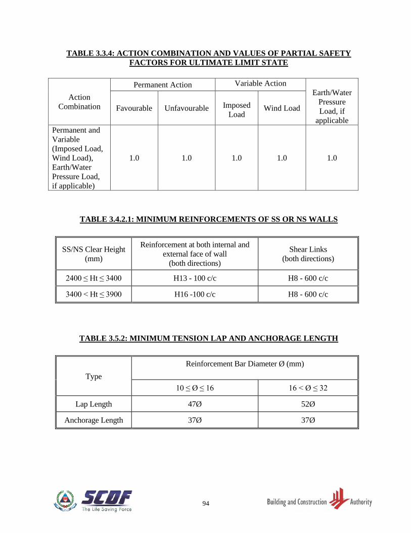
94
TABLE 3.3.4: ACTION COMBINATION AND VALUES OF PARTIAL SAFETY
FACTORS FOR ULTIMATE LIMIT STATE
Action
Combination
Permanent Action Variable Action
Earth/Water
Pressure
Load, if
applicable
Favourable Unfavourable
Imposed
Load Wind Load
Permanent and
Variable
(Imposed Load,
Wind Load),
Earth/Water
Pressure Load,
if applicable)
1.0 1.0 1.0 1.0 1.0
TABLE 3.4.2.1: MINIMUM REINFORCEMENTS OF SS OR NS WALLS
SS/NS Clear Height
(mm)
Reinforcement at both internal and
external face of wall
(both directions)
Shear Links
(both directions)
2400 ≤ Ht ≤ 3400 H13 - 100 c/c H8 - 600 c/c
3400 < Ht ≤ 3900 H16 -100 c/c H8 - 600 c/c
TABLE 3.5.2: MINIMUM TENSION LAP AND ANCHORAGE LENGTH
Type
Reinforcement Bar Diameter Ø (mm)
10 ≤ Ø ≤ 16 16 < Ø ≤ 32
Lap Length 47Ø 52Ø
Anchorage Length 37Ø 37Ø
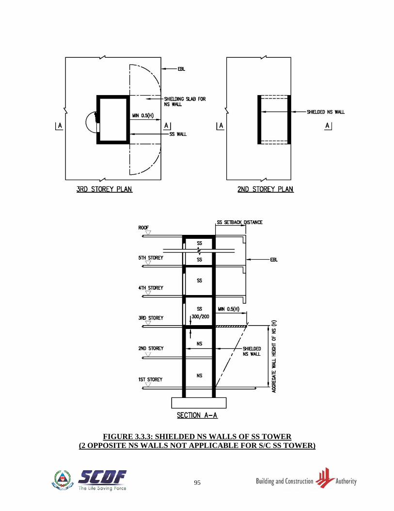
95
FIGURE 3.3.3: SHIELDED NS WALLS OF SS TOWER
(2 OPPOSITE NS WALLS NOT APPLICABLE FOR S/C SS TOWER)
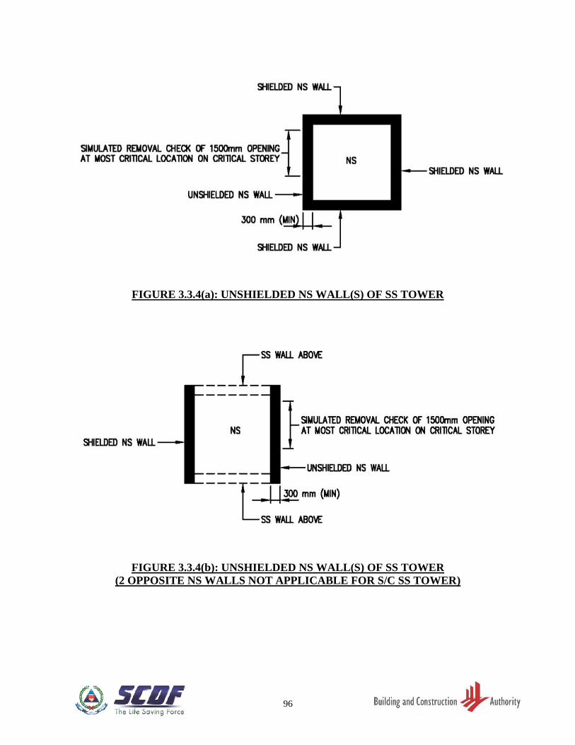
96
FIGURE 3.3.4(a): UNSHIELDED NS WALL(S) OF SS TOWER
FIGURE 3.3.4(b): UNSHIELDED NS WALL(S) OF SS TOWER
(2 OPPOSITE NS WALLS NOT APPLICABLE FOR S/C SS TOWER)
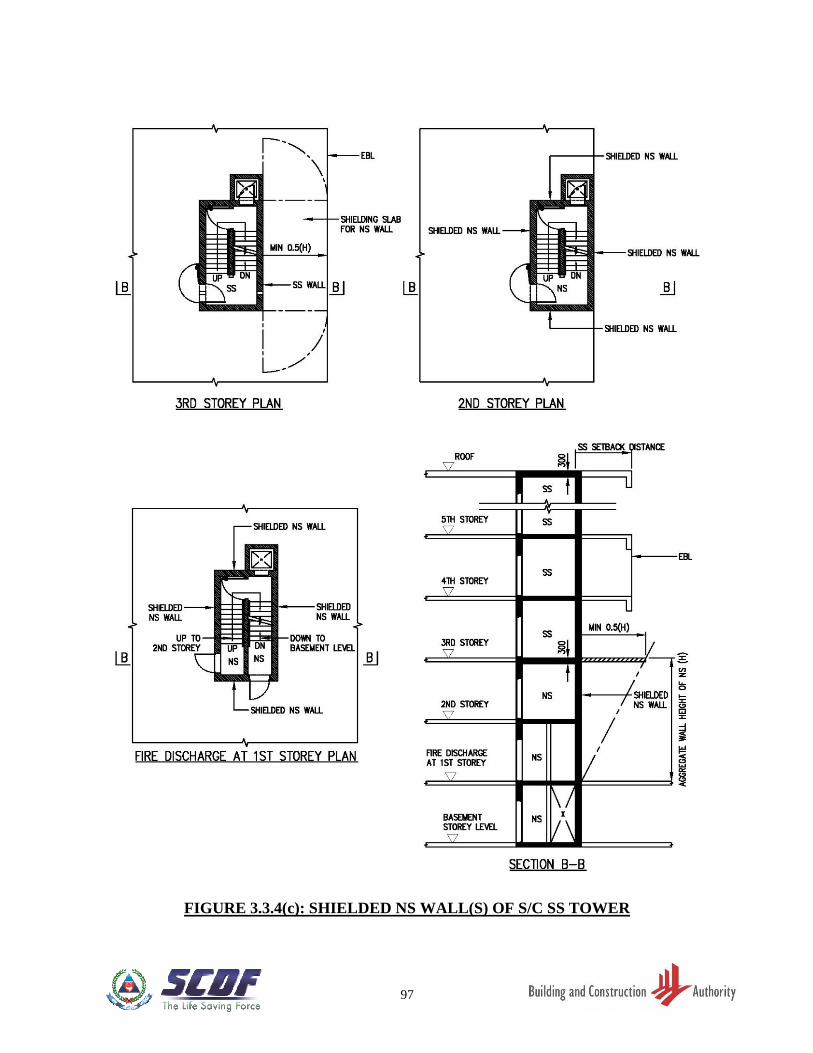
97
FIGURE 3.3.4(c): SHIELDED NS WALL(S) OF S/C SS TOWER
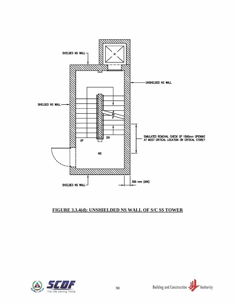
98
FIGURE 3.3.4(d): UNSHIELDED NS WALL OF S/C SS TOWER
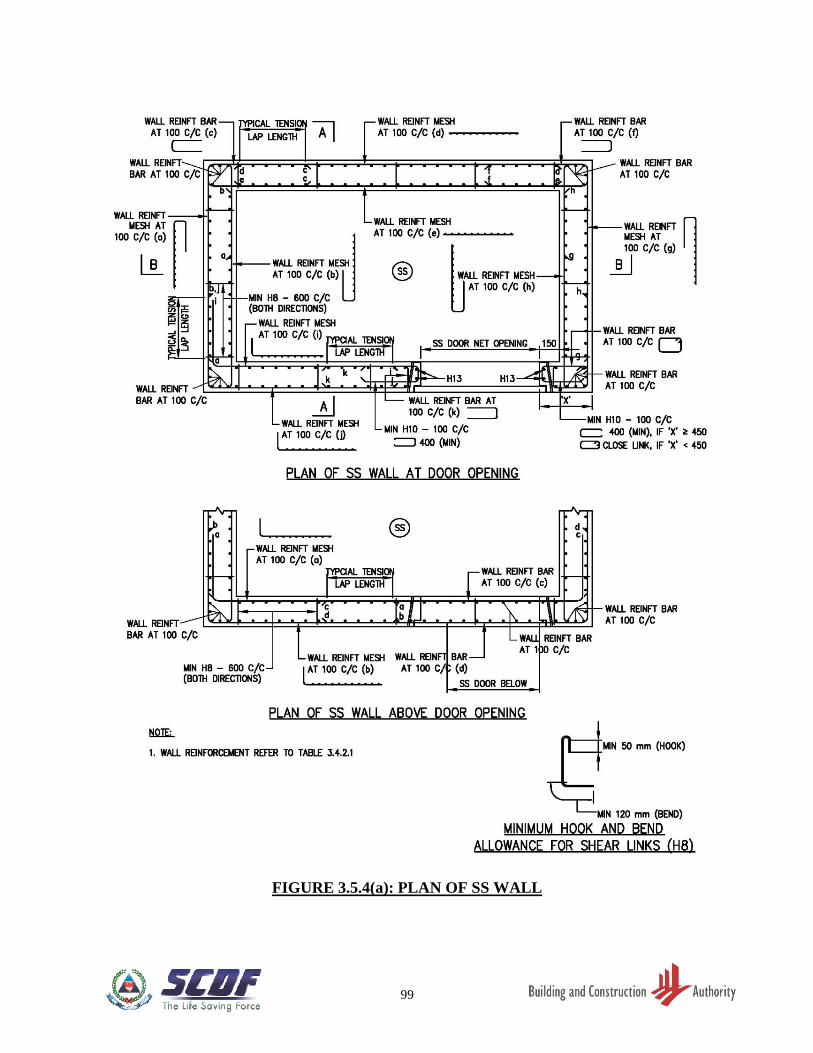
99
FIGURE 3.5.4(a): PLAN OF SS WALL
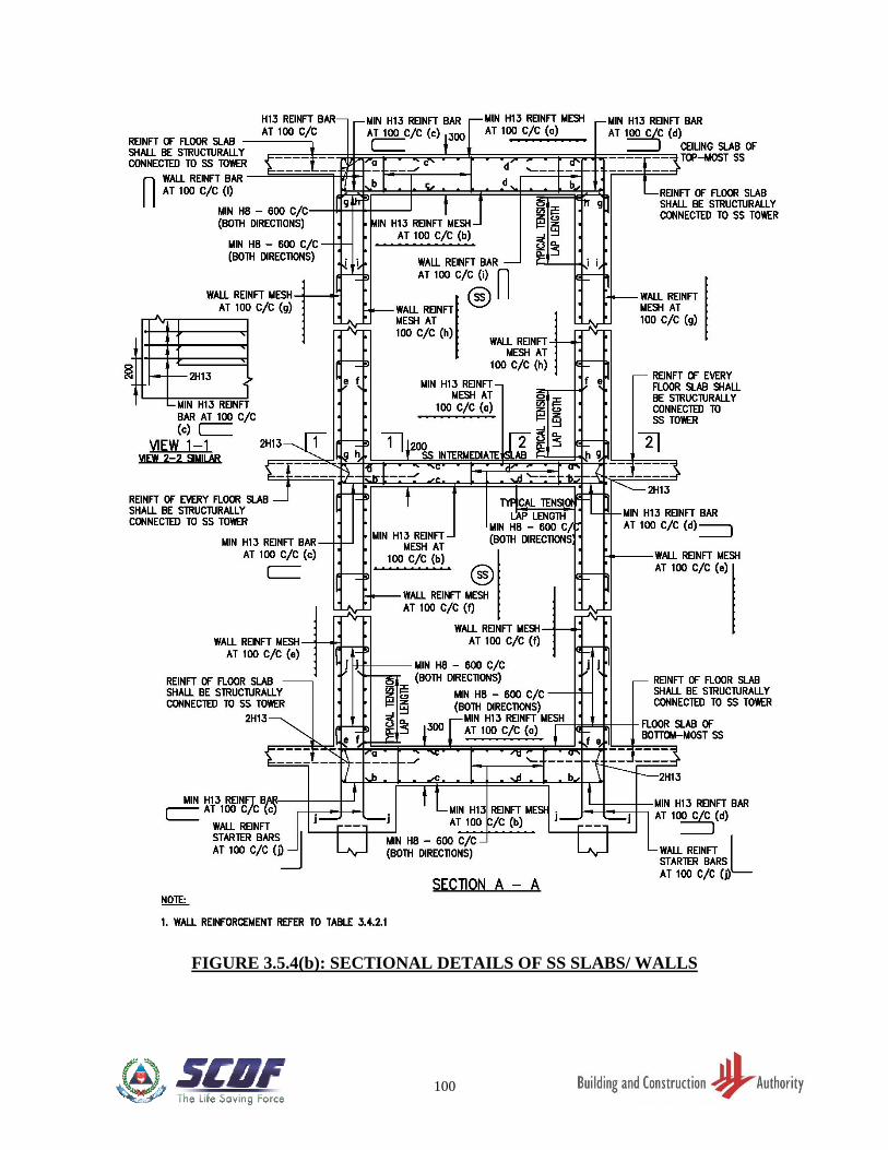
100
FIGURE 3.5.4(b): SECTIONAL DETAILS OF SS SLABS/ WALLS
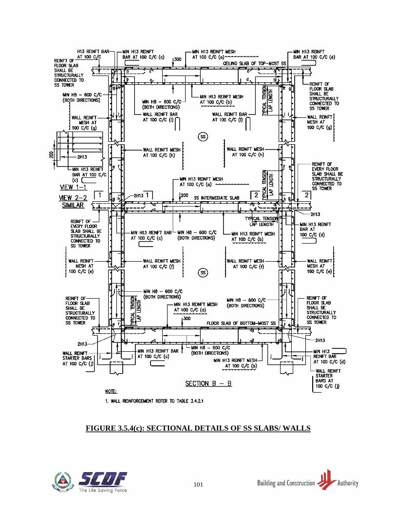
101
FIGURE 3.5.4(c): SECTIONAL DETAILS OF SS SLABS/ WALLS
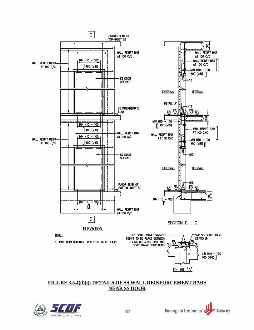
102
FIGURE 3.5.4(d)(i): DETAILS OF SS WALL REINFORCEMENT BARS
NEAR SS DOOR
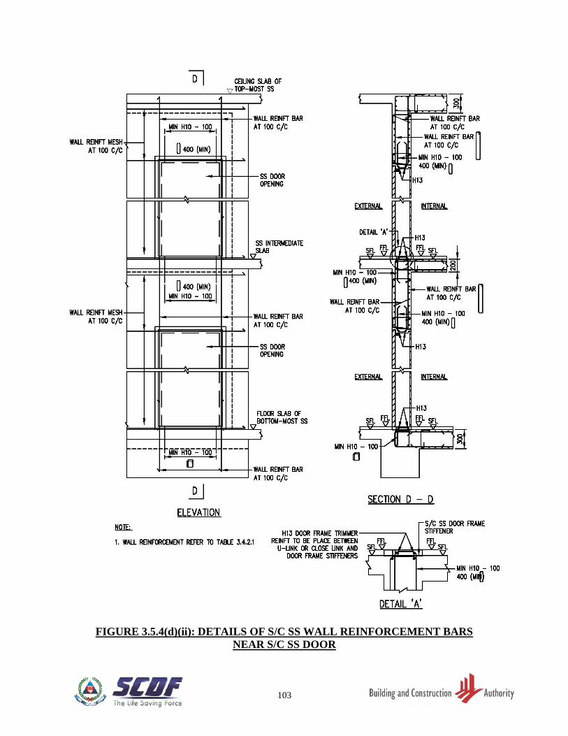
103
FIGURE 3.5.4(d)(ii): DETAILS OF S/C SS WALL REINFORCEMENT BARS
NEAR S/C SS DOOR
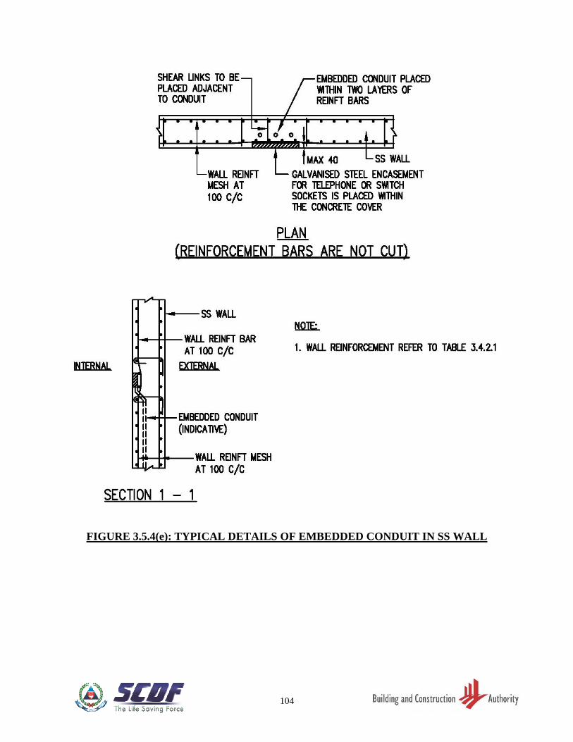
104
FIGURE 3.5.4(e): TYPICAL DETAILS OF EMBEDDED CONDUIT IN SS WALL
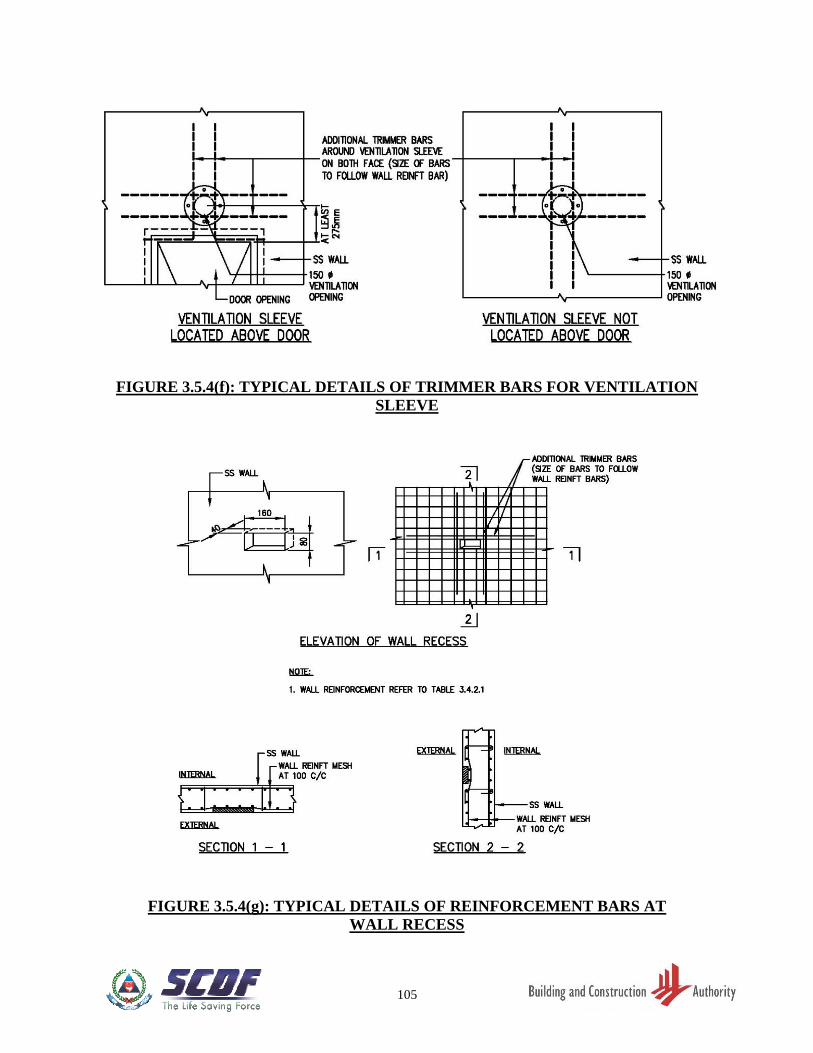
105
FIGURE 3.5.4(f): TYPICAL DETAILS OF TRIMMER BARS FOR VENTILATION
SLEEVE
FIGURE 3.5.4(g): TYPICAL DETAILS OF REINFORCEMENT BARS AT
WALL RECESS
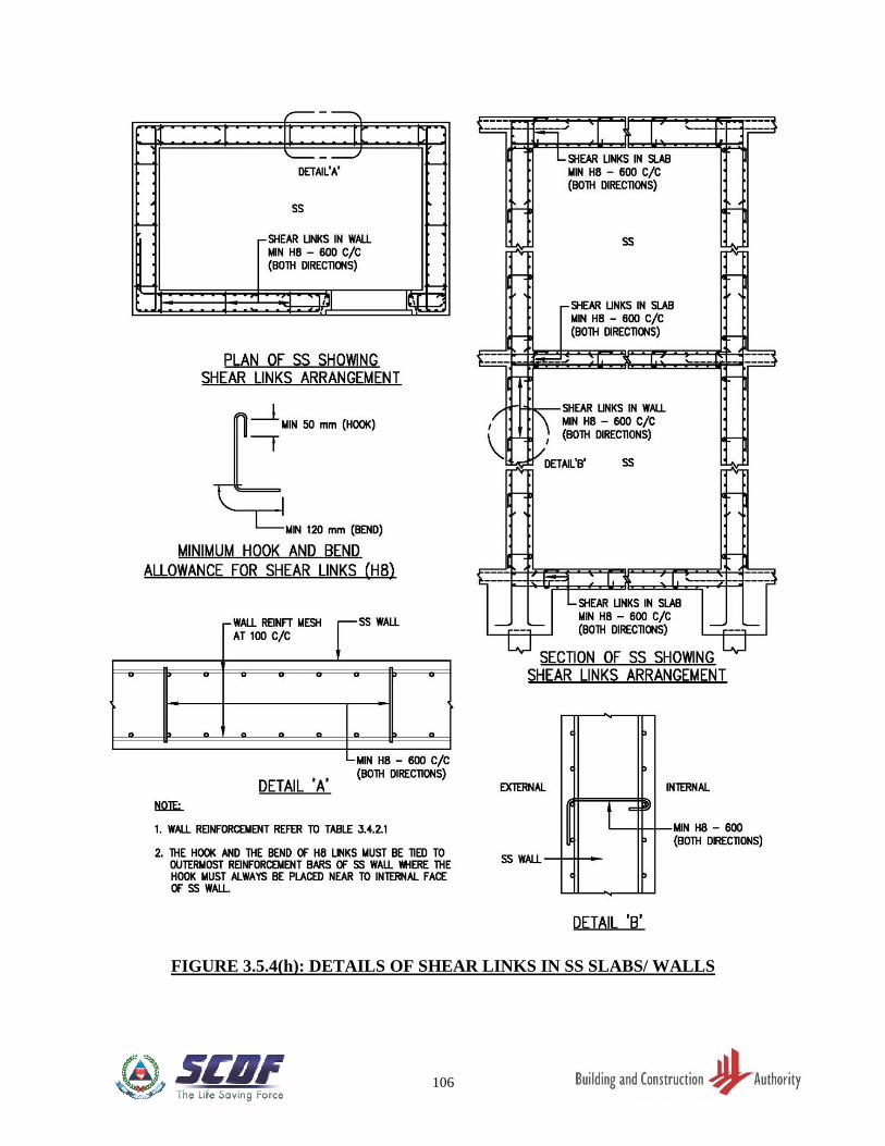
106
FIGURE 3.5.4(h): DETAILS OF SHEAR LINKS IN SS SLABS/ WALLS
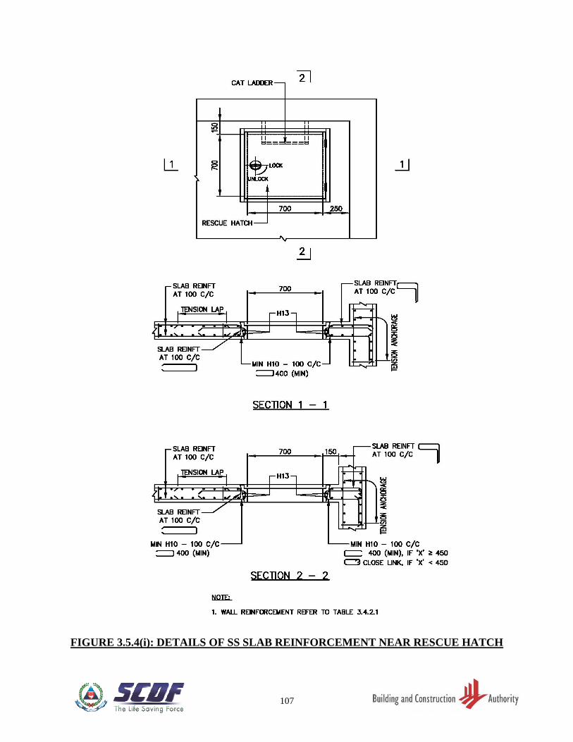
107
FIGURE 3.5.4(i): DETAILS OF SS SLAB REINFORCEMENT NEAR RESCUE HATCH
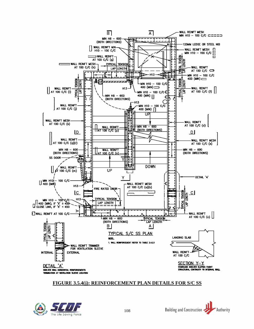
108
FIGURE 3.5.4(j): REINFORCEMENT PLAN DETAILS FOR S/C SS
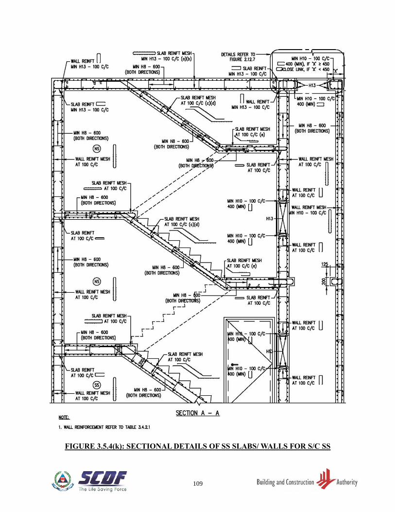
109
FIGURE 3.5.4(k): SECTIONAL DETAILS OF SS SLABS/ WALLS FOR S/C SS
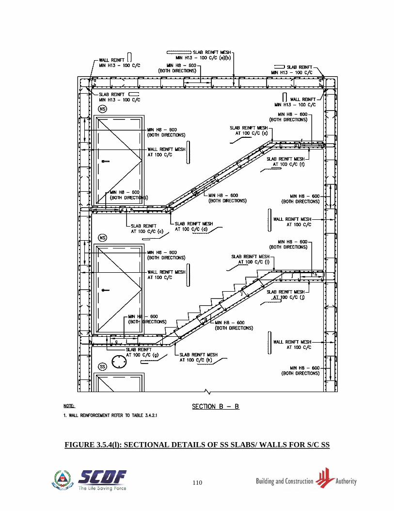
110
FIGURE 3.5.4(l): SECTIONAL DETAILS OF SS SLABS/ WALLS FOR S/C SS
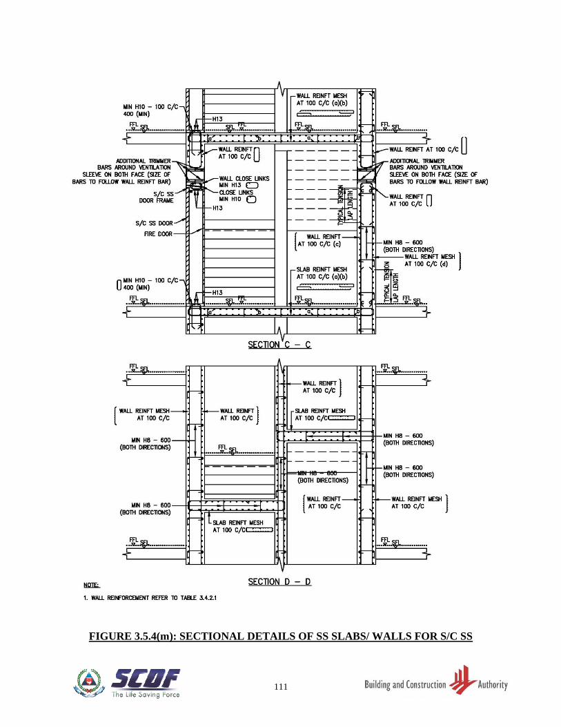
111
FIGURE 3.5.4(m): SECTIONAL DETAILS OF SS SLABS/ WALLS FOR S/C SS
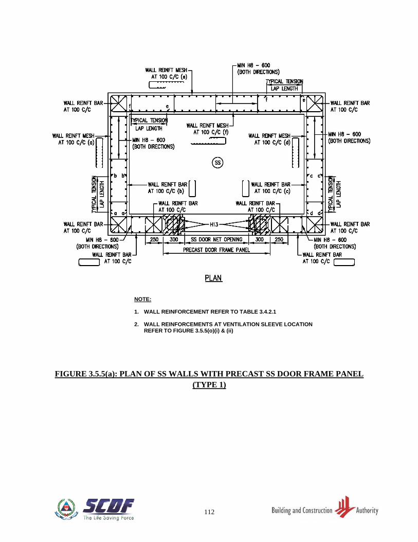
112
FIGURE 3.5.5(a): PLAN OF SS WALLS WITH PRECAST SS DOOR FRAME PANEL
(TYPE 1)
NOTE: 1. WALL REINFORCEMENT REFER TO TABLE 3.4.2.1 2. WALL REINFORCEMENTS AT VENTILATION SLEEVE LOCATION
REFER TO FIGURE 3.5.5(o)(i) & (ii)
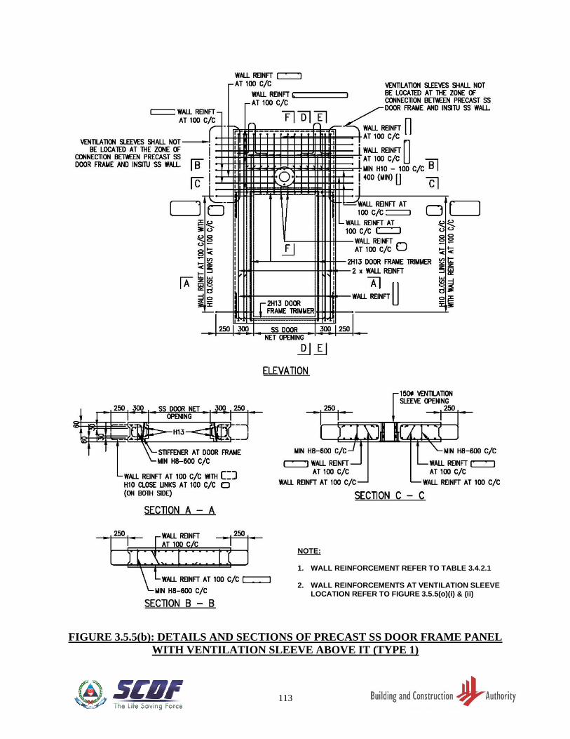
113
FIGURE 3.5.5(b): DETAILS AND SECTIONS OF PRECAST SS DOOR FRAME PANEL
WITH VENTILATION SLEEVE ABOVE IT (TYPE 1)
NOTE: 1. WALL REINFORCEMENT REFER TO TABLE 3.4.2.1 2. WALL REINFORCEMENTS AT VENTILATION SLEEVE
LOCATION REFER TO FIGURE 3.5.5(o)(i) & (ii)
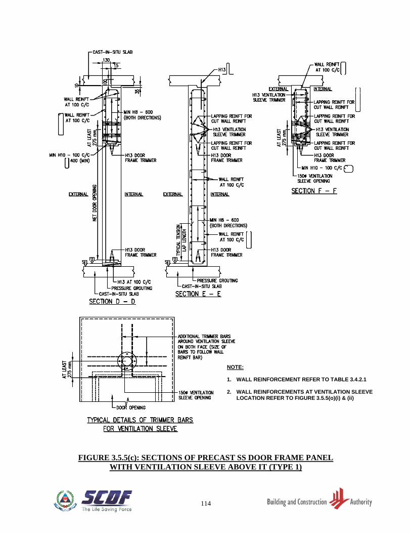
114
FIGURE 3.5.5(c): SECTIONS OF PRECAST SS DOOR FRAME PANEL
WITH VENTILATION SLEEVE ABOVE IT (TYPE 1)
NOTE: 1. WALL REINFORCEMENT REFER TO TABLE 3.4.2.1 2. WALL REINFORCEMENTS AT VENTILATION SLEEVE
LOCATION REFER TO FIGURE 3.5.5(o)(i) & (ii)
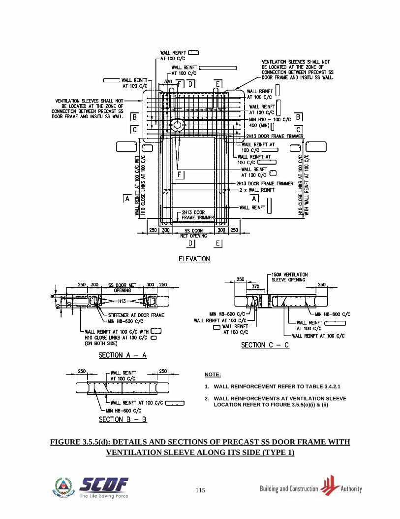
115
FIGURE 3.5.5(d): DETAILS AND SECTIONS OF PRECAST SS DOOR FRAME WITH
VENTILATION SLEEVE ALONG ITS SIDE (TYPE 1)
NOTE: 1. WALL REINFORCEMENT REFER TO TABLE 3.4.2.1 2. WALL REINFORCEMENTS AT VENTILATION SLEEVE
LOCATION REFER TO FIGURE 3.5.5(o)(i) & (ii)
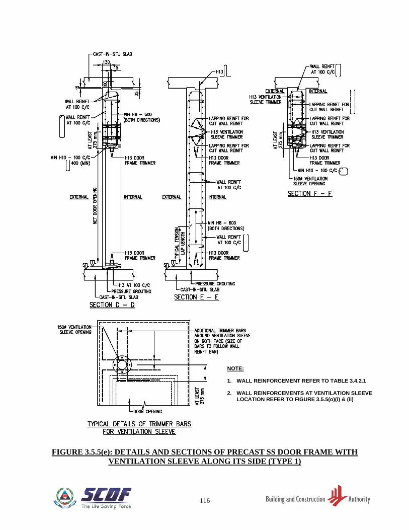
116
FIGURE 3.5.5(e): DETAILS AND SECTIONS OF PRECAST SS DOOR FRAME WITH
VENTILATION SLEEVE ALONG ITS SIDE (TYPE 1)
NOTE: 1. WALL REINFORCEMENT REFER TO TABLE 3.4.2.1 2. WALL REINFORCEMENTS AT VENTILATION SLEEVE
LOCATION REFER TO FIGURE 3.5.5(o)(i) & (ii)
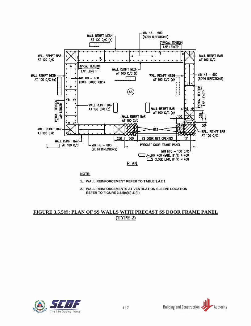
117
FIGURE 3.5.5(f): PLAN OF SS WALLS WITH PRECAST SS DOOR FRAME PANEL
(TYPE 2)
NOTE: 1. WALL REINFORCEMENT REFER TO TABLE 3.4.2.1 2. WALL REINFORCEMENTS AT VENTILATION SLEEVE LOCATION
REFER TO FIGURE 3.5.5(o)(i) & (ii)
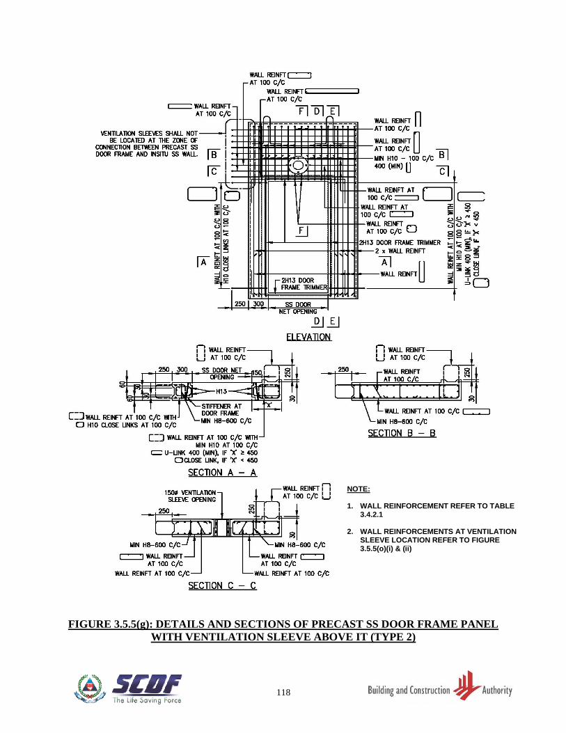
118
FIGURE 3.5.5(g): DETAILS AND SECTIONS OF PRECAST SS DOOR FRAME PANEL
WITH VENTILATION SLEEVE ABOVE IT (TYPE 2)
NOTE: 1. WALL REINFORCEMENT REFER TO TABLE
3.4.2.1 2. WALL REINFORCEMENTS AT VENTILATION
SLEEVE LOCATION REFER TO FIGURE
3.5.5(o)(i) & (ii)
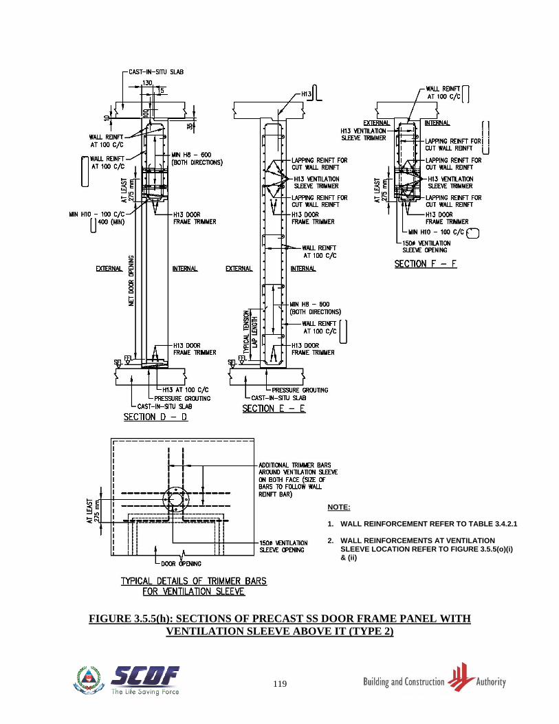
119
FIGURE 3.5.5(h): SECTIONS OF PRECAST SS DOOR FRAME PANEL WITH
VENTILATION SLEEVE ABOVE IT (TYPE 2)
NOTE: 1. WALL REINFORCEMENT REFER TO TABLE 3.4.2.1 2. WALL REINFORCEMENTS AT VENTILATION
SLEEVE LOCATION REFER TO FIGURE 3.5.5(o)(i) & (ii)
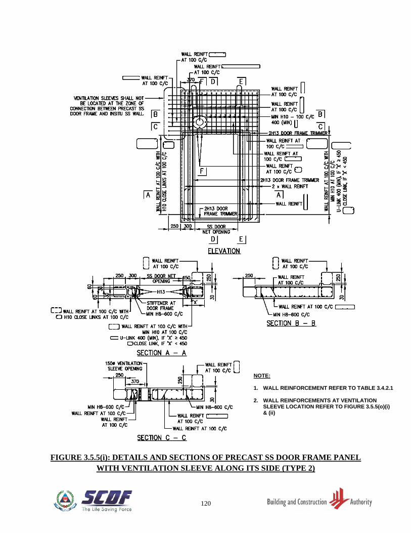
120
FIGURE 3.5.5(i): DETAILS AND SECTIONS OF PRECAST SS DOOR FRAME PANEL
WITH VENTILATION SLEEVE ALONG ITS SIDE (TYPE 2)
NOTE: 1. WALL REINFORCEMENT REFER TO TABLE 3.4.2.1
2. WALL REINFORCEMENTS AT VENTILATION
SLEEVE LOCATION REFER TO FIGURE 3.5.5(o)(i) & (ii)
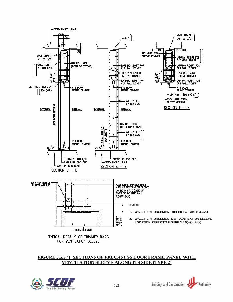
121
FIGURE 3.5.5(j): SECTIONS OF PRECAST SS DOOR FRAME PANEL WITH
VENTILATION SLEEVE ALONG ITS SIDE (TYPE 2)
NOTE: 1. WALL REINFORCEMENT REFER TO TABLE 3.4.2.1 2. WALL REINFORCEMENTS AT VENTILATION SLEEVE
LOCATION REFER TO FIGURE 3.5.5(o)(i) & (ii)
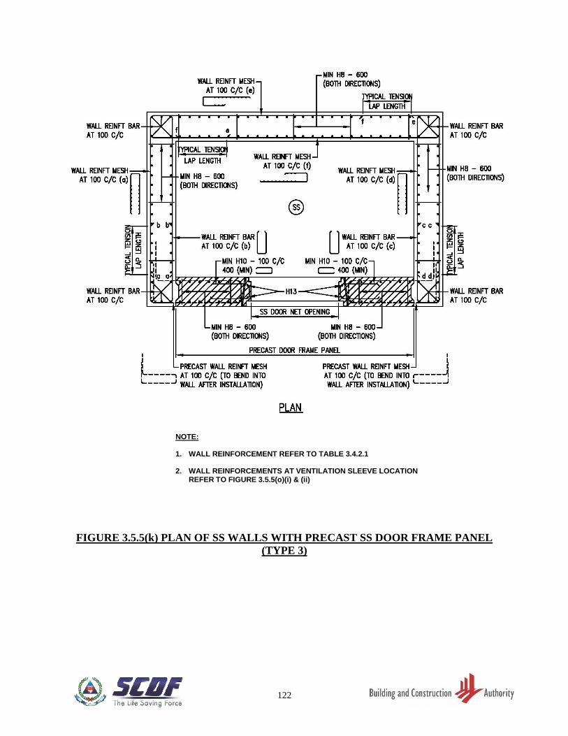
122
FIGURE 3.5.5(k) PLAN OF SS WALLS WITH PRECAST SS DOOR FRAME PANEL
(TYPE 3)
NOTE: 1. WALL REINFORCEMENT REFER TO TABLE 3.4.2.1 2. WALL REINFORCEMENTS AT VENTILATION SLEEVE LOCATION
REFER TO FIGURE 3.5.5(o)(i) & (ii)
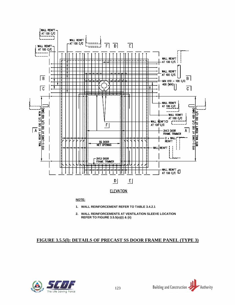
123
FIGURE 3.5.5(l): DETAILS OF PRECAST SS DOOR FRAME PANEL (TYPE 3)
NOTE: 1. WALL REINFORCEMENT REFER TO TABLE 3.4.2.1 2. WALL REINFORCEMENTS AT VENTILATION SLEEVE LOCATION
REFER TO FIGURE 3.5.5(o)(i) & (ii)
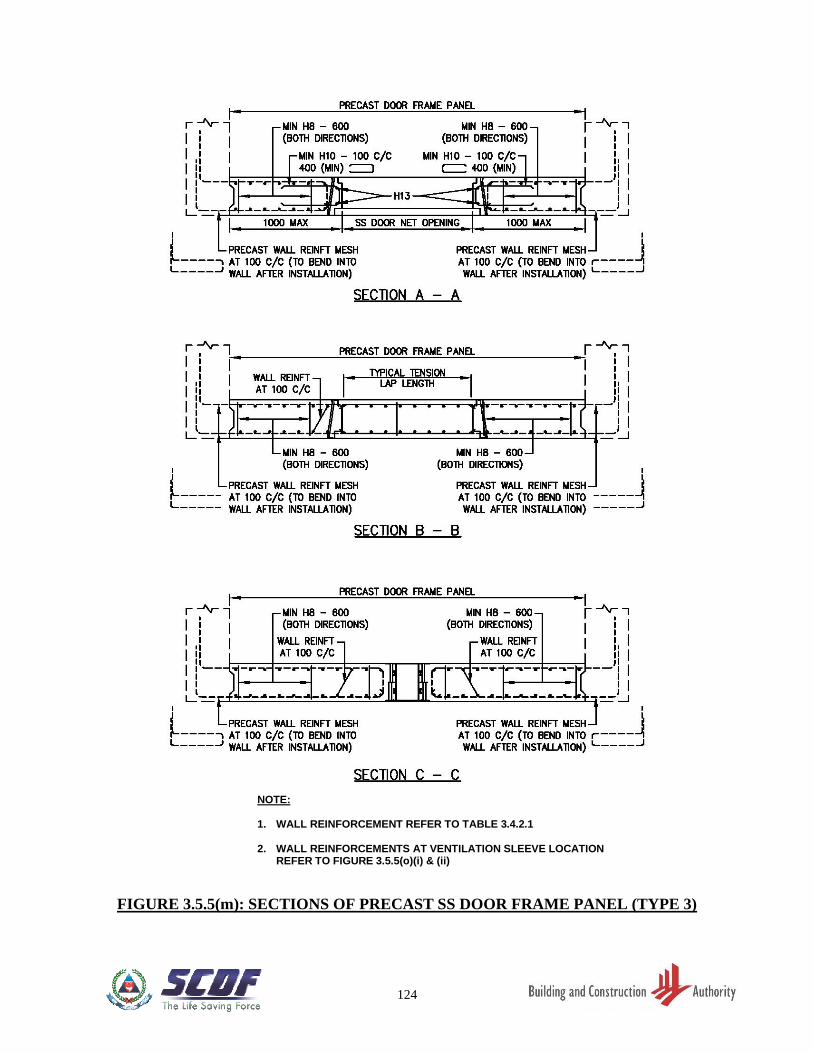
124
FIGURE 3.5.5(m): SECTIONS OF PRECAST SS DOOR FRAME PANEL (TYPE 3)
NOTE: 1. WALL REINFORCEMENT REFER TO TABLE 3.4.2.1 2. WALL REINFORCEMENTS AT VENTILATION SLEEVE LOCATION
REFER TO FIGURE 3.5.5(o)(i) & (ii)
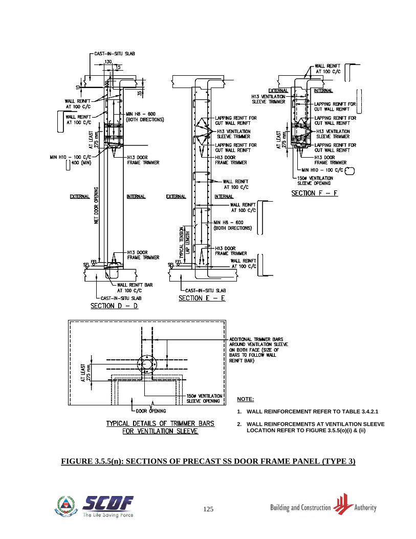
125
FIGURE 3.5.5(n): SECTIONS OF PRECAST SS DOOR FRAME PANEL (TYPE 3)
NOTE: 1. WALL REINFORCEMENT REFER TO TABLE 3.4.2.1 2. WALL REINFORCEMENTS AT VENTILATION SLEEVE
LOCATION REFER TO FIGURE 3.5.5(o)(i) & (ii)
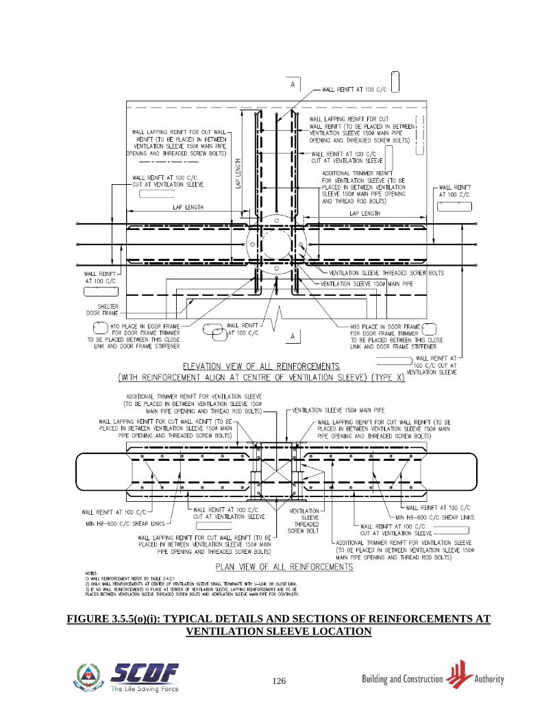
126
FIGURE 3.5.5(o)(i): TYPICAL DETAILS AND SECTIONS OF REINFORCEMENTS AT
VENTILATION SLEEVE LOCATION
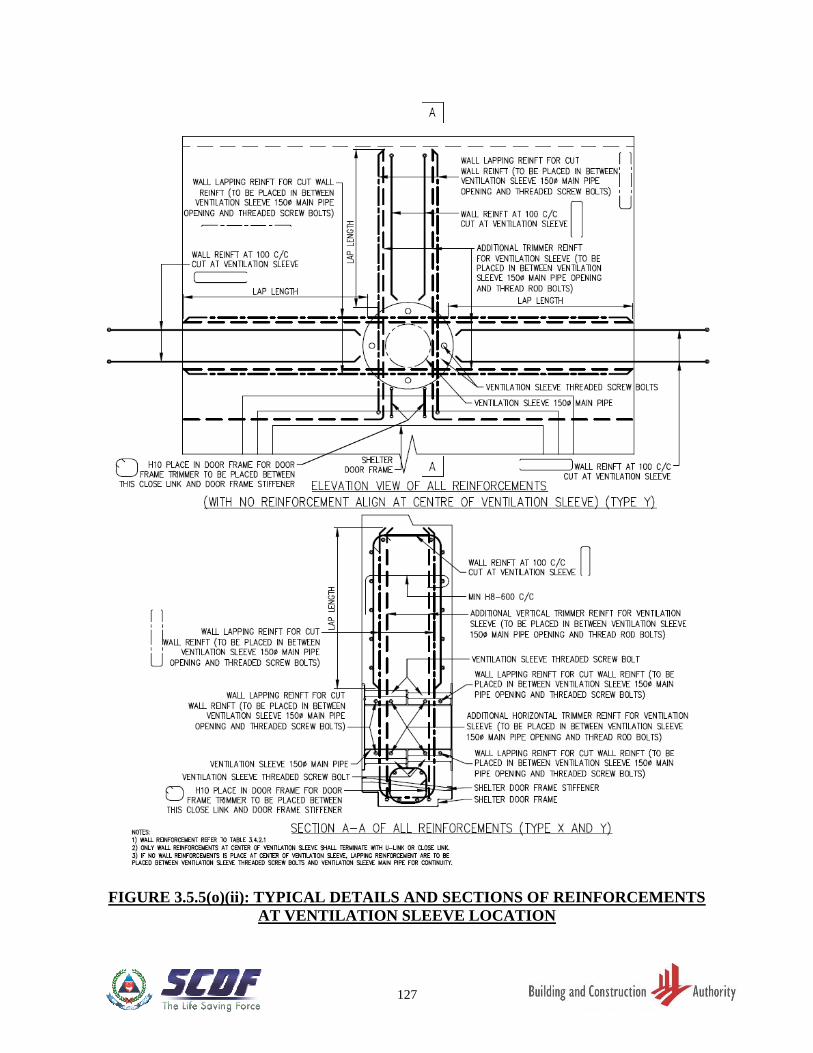
127
FIGURE 3.5.5(o)(ii): TYPICAL DETAILS AND SECTIONS OF REINFORCEMENTS
AT VENTILATION SLEEVE LOCATION
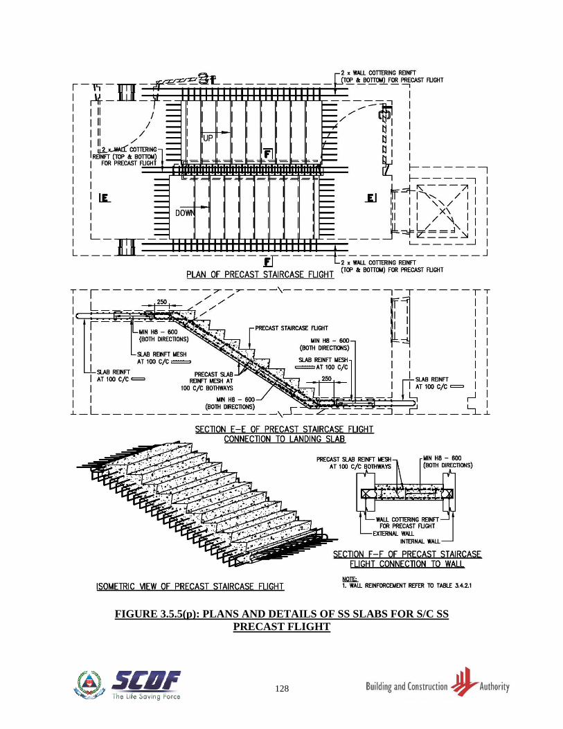
128
FIGURE 3.5.5(p): PLANS AND DETAILS OF SS SLABS FOR S/C SS
PRECAST FLIGHT
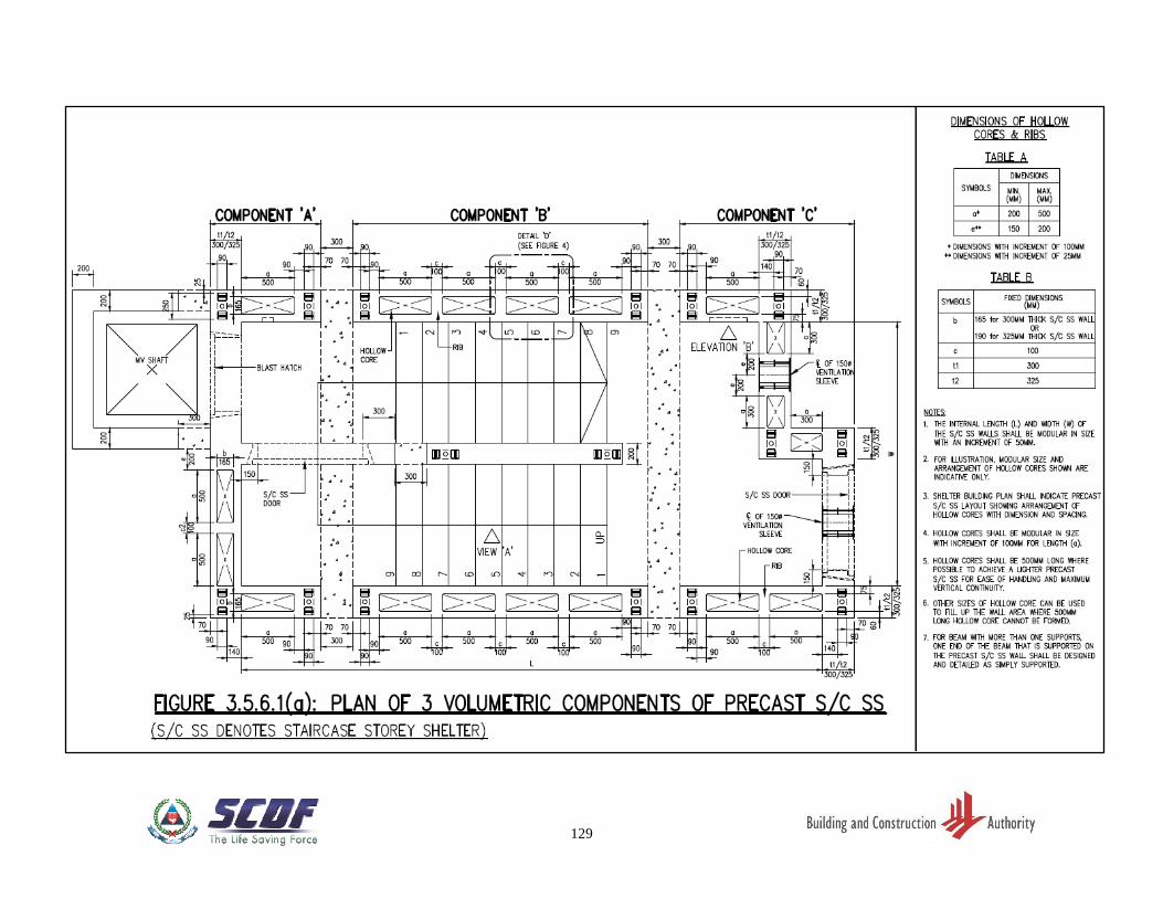
129
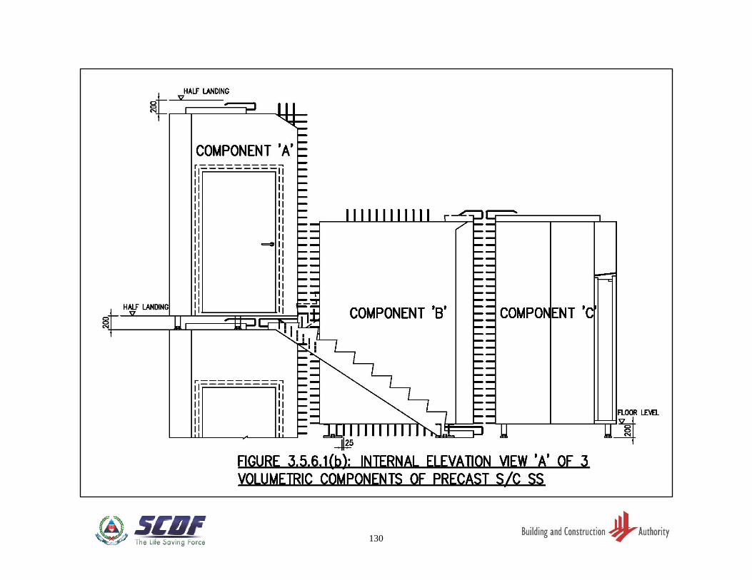
130
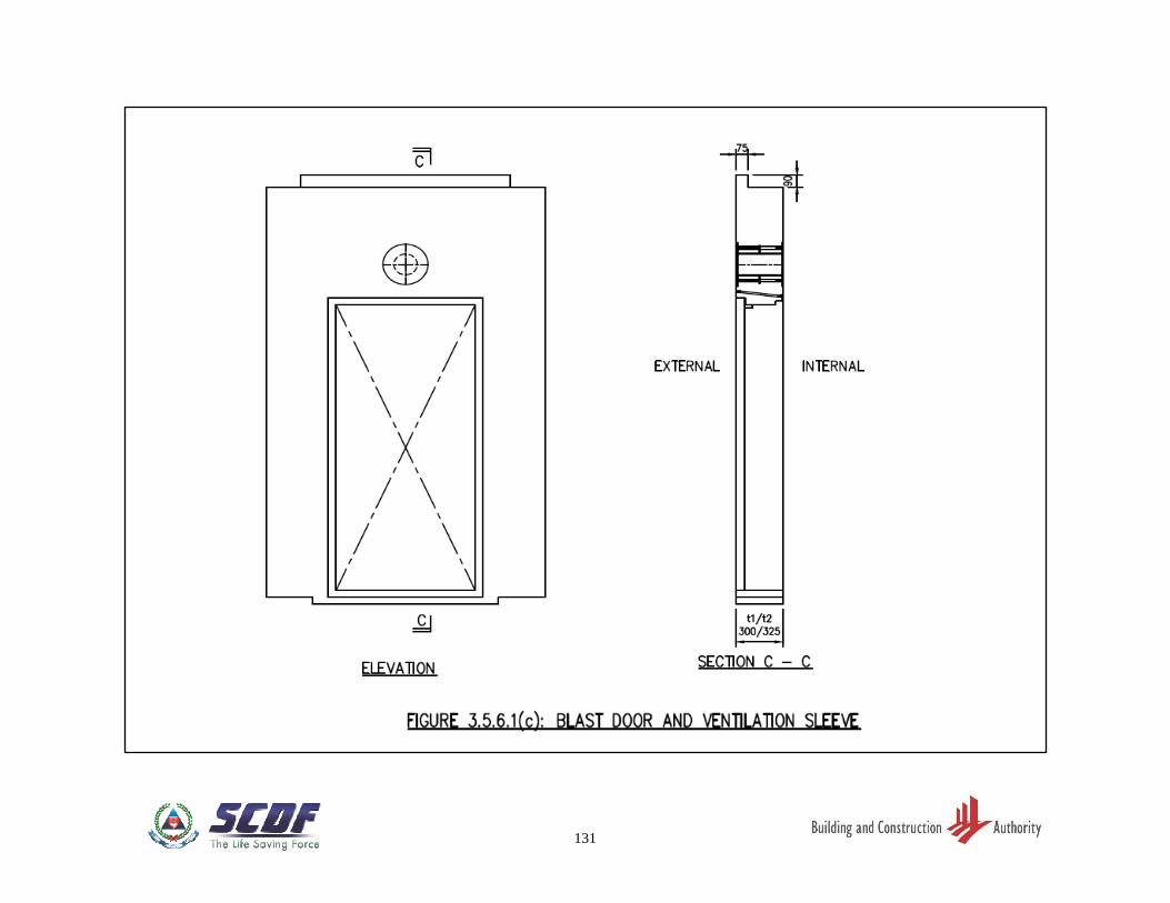
131
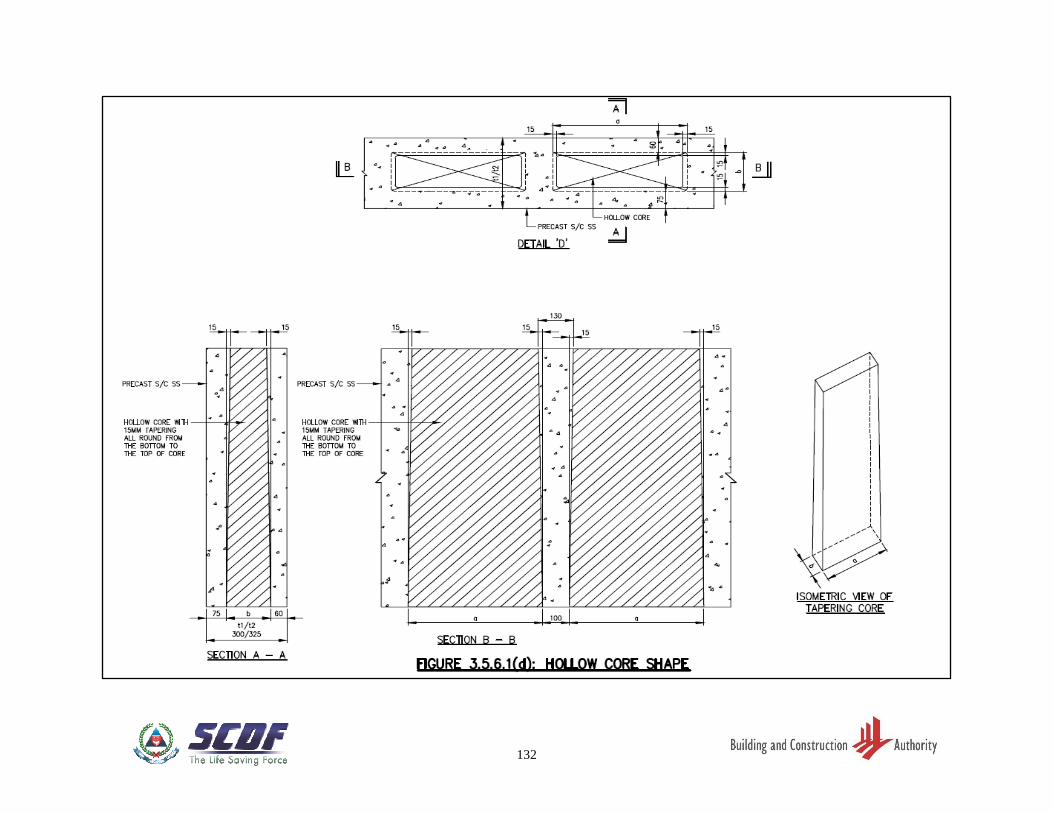
132
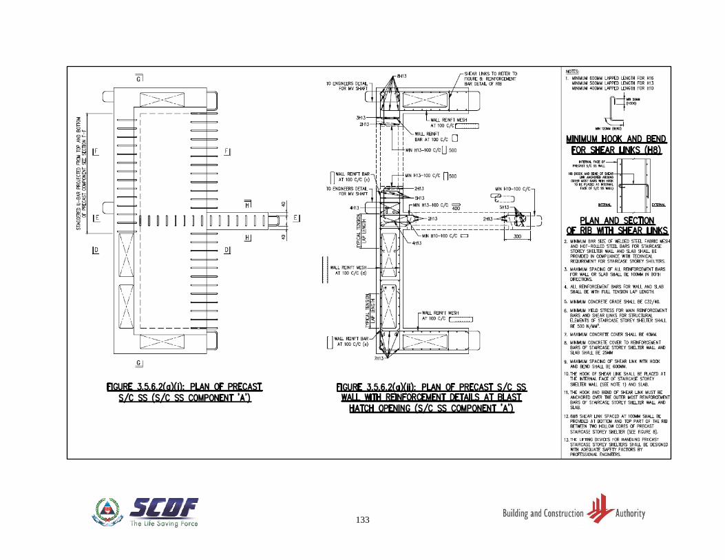
133
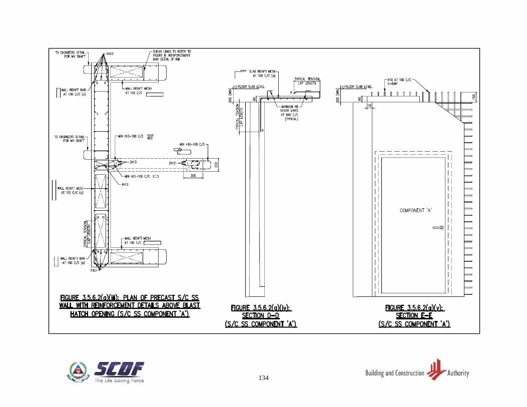
134
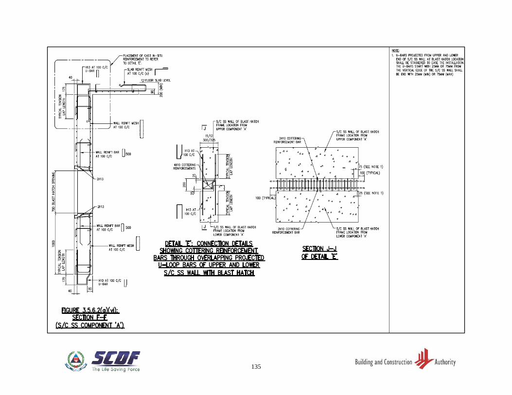
135
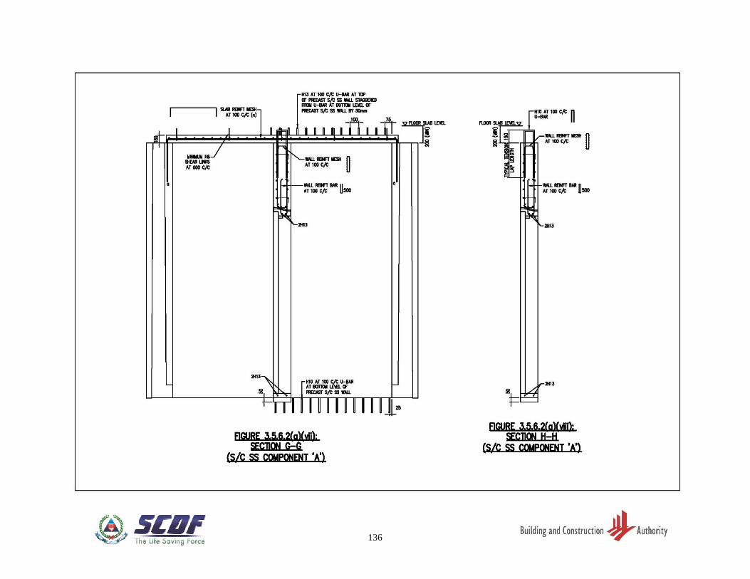
136
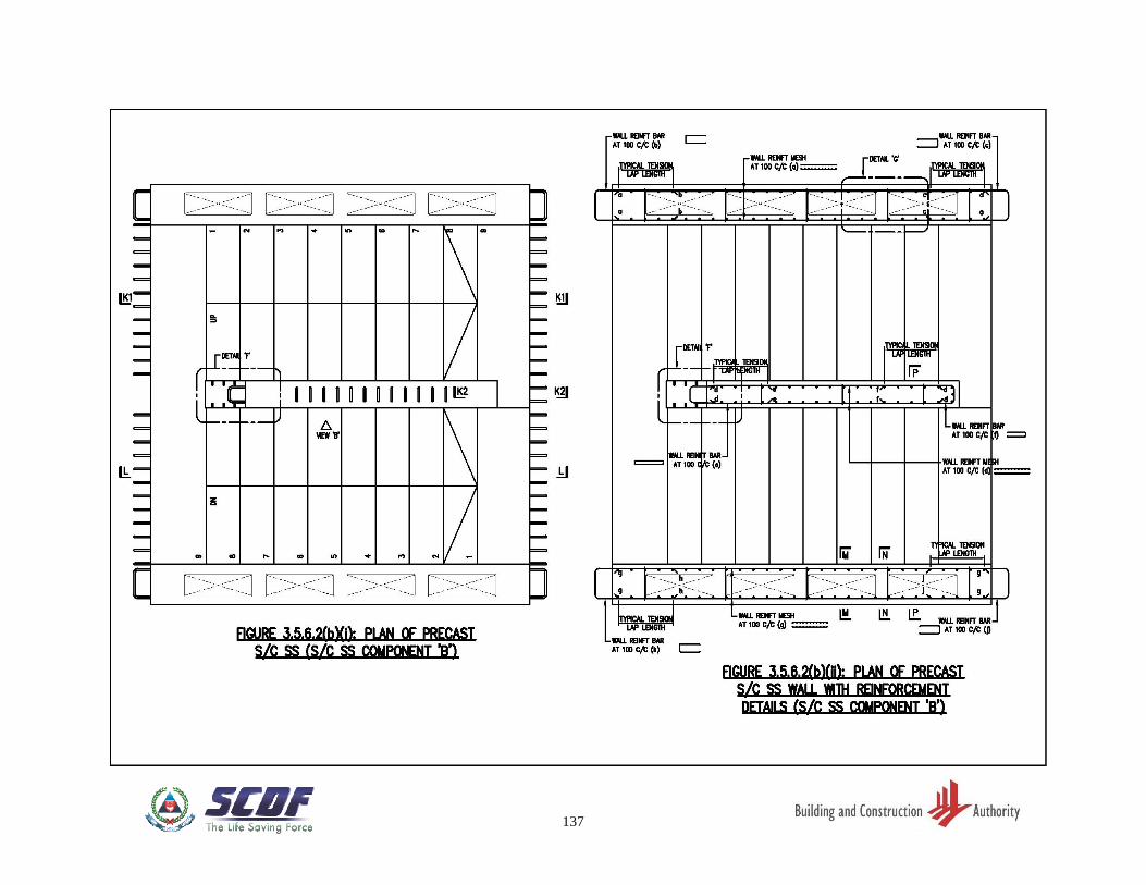
137
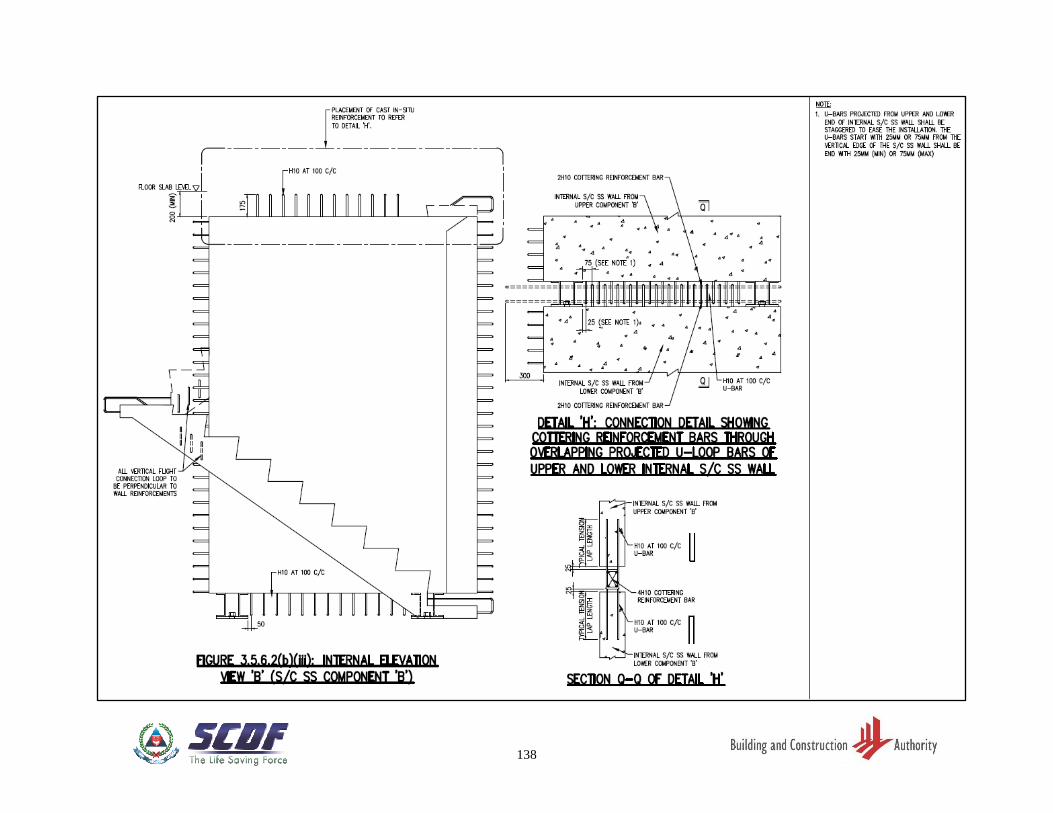
138
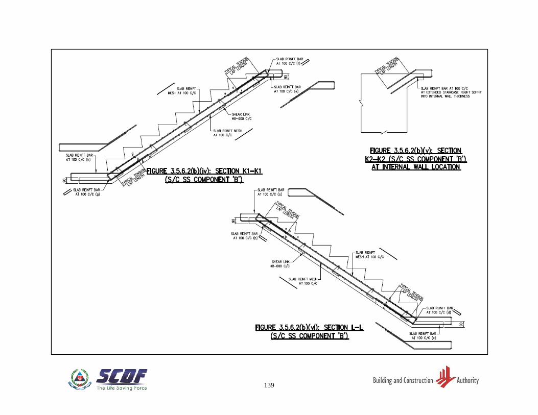
139
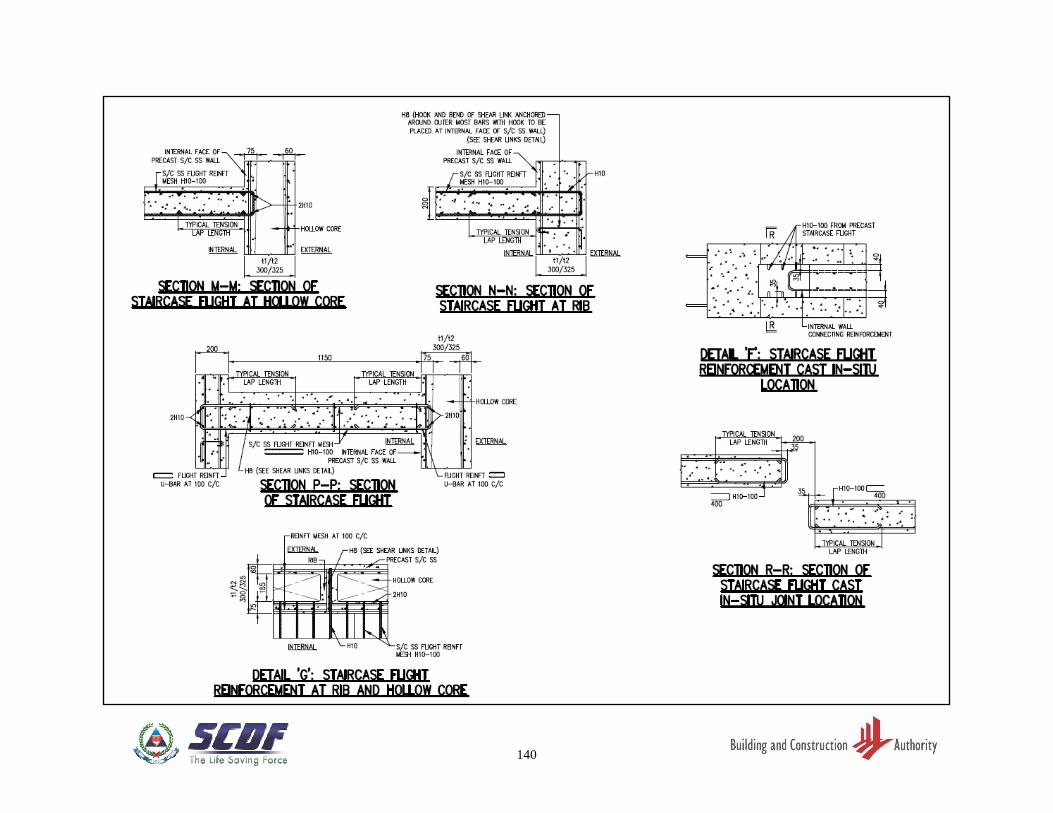
140
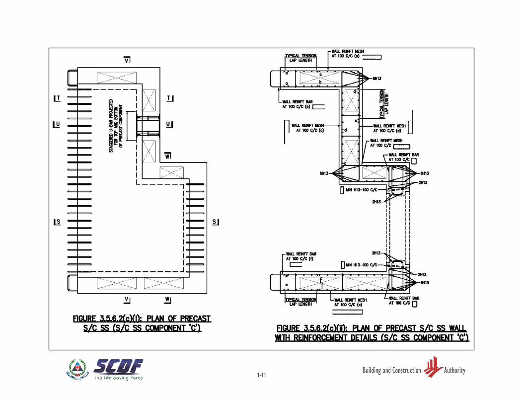
141
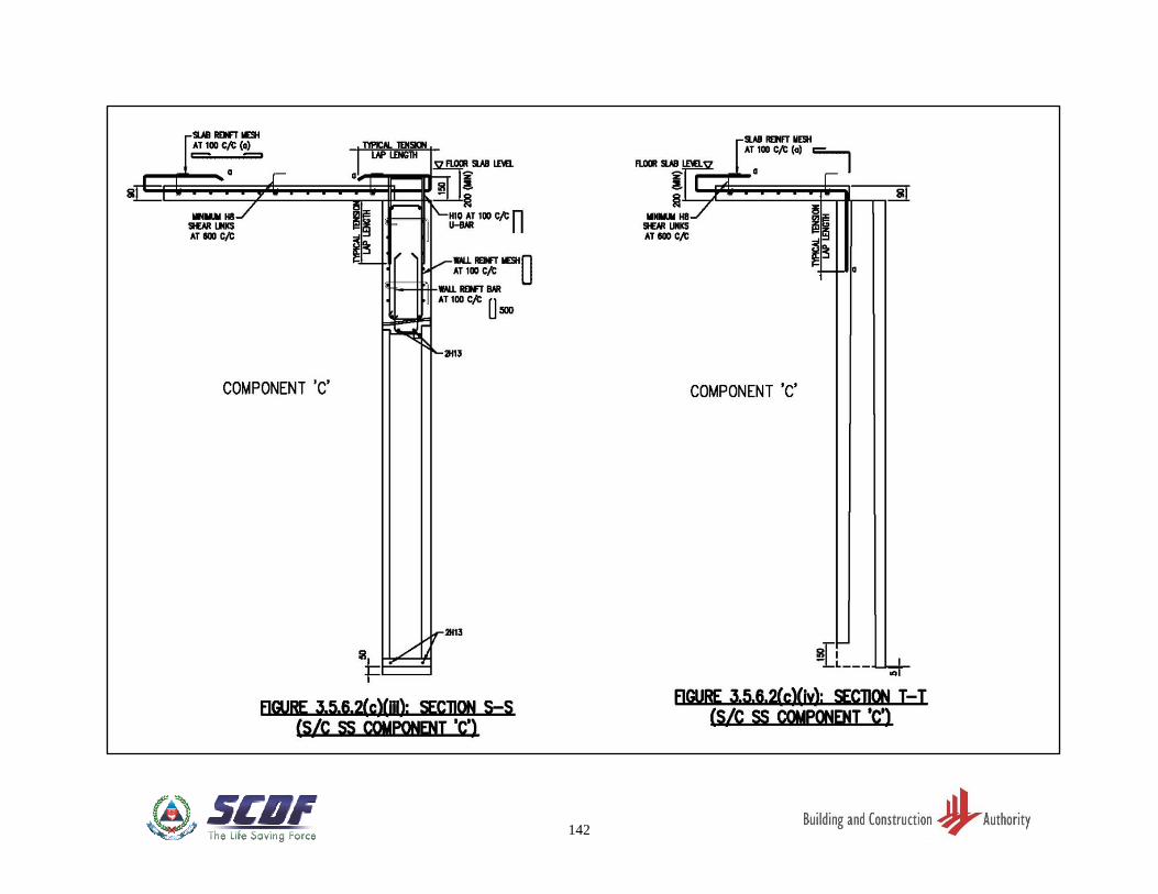
142
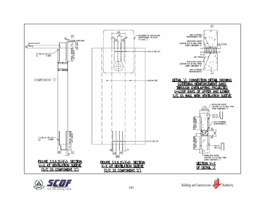
143
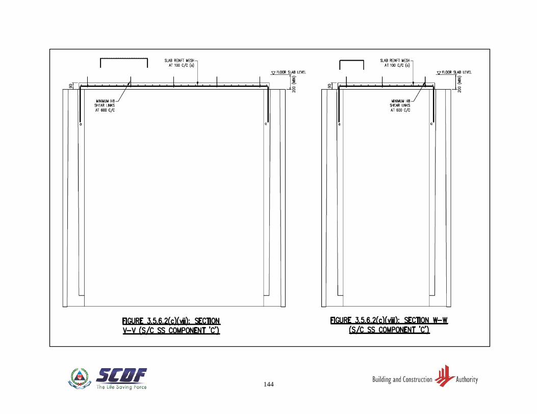
144
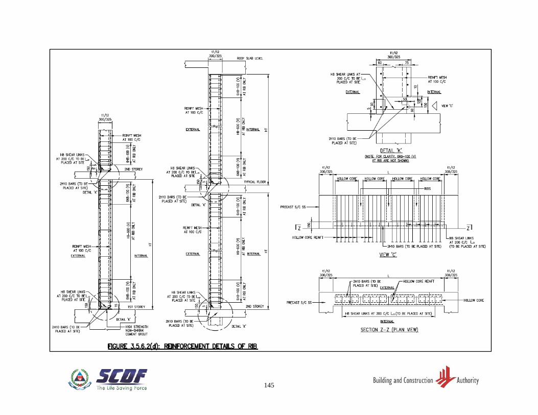
145
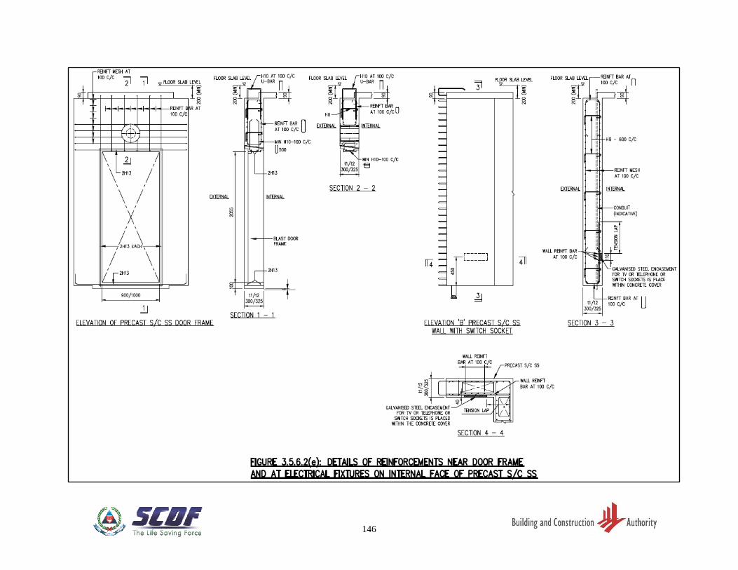
146
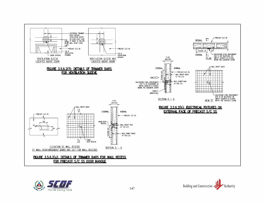
147
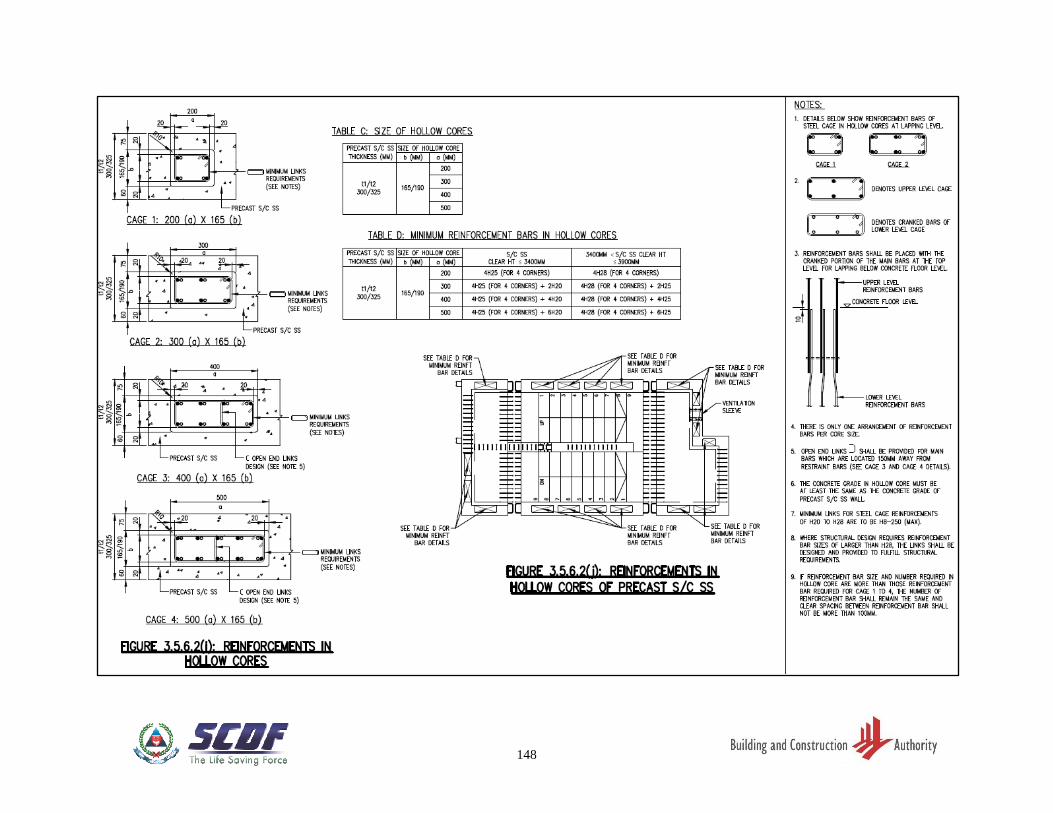
148
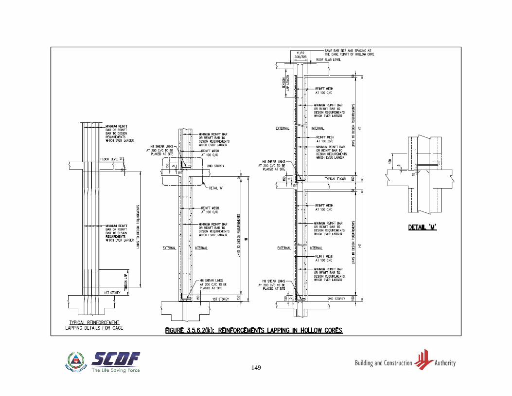
149
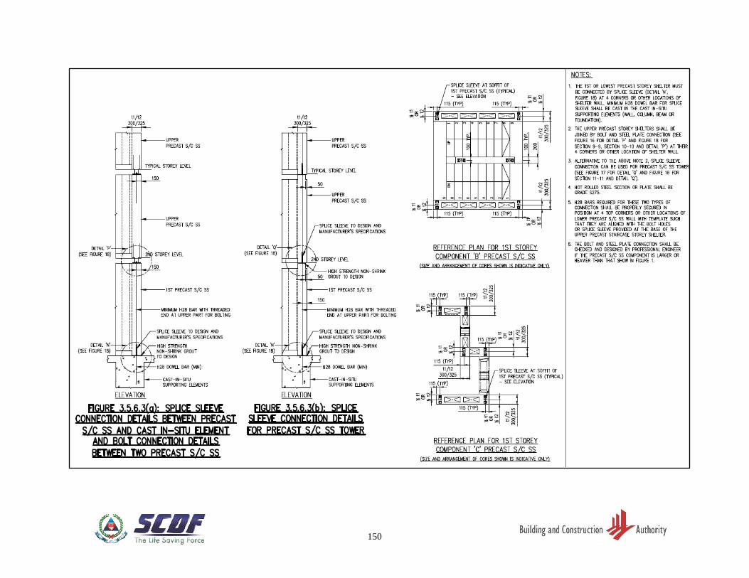
150
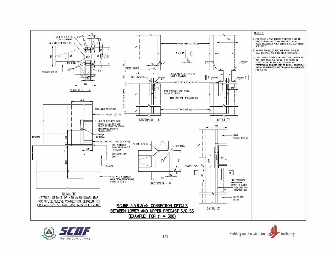
151
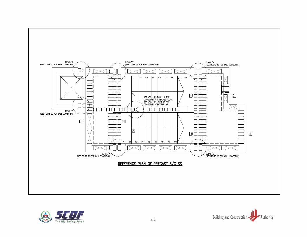
152
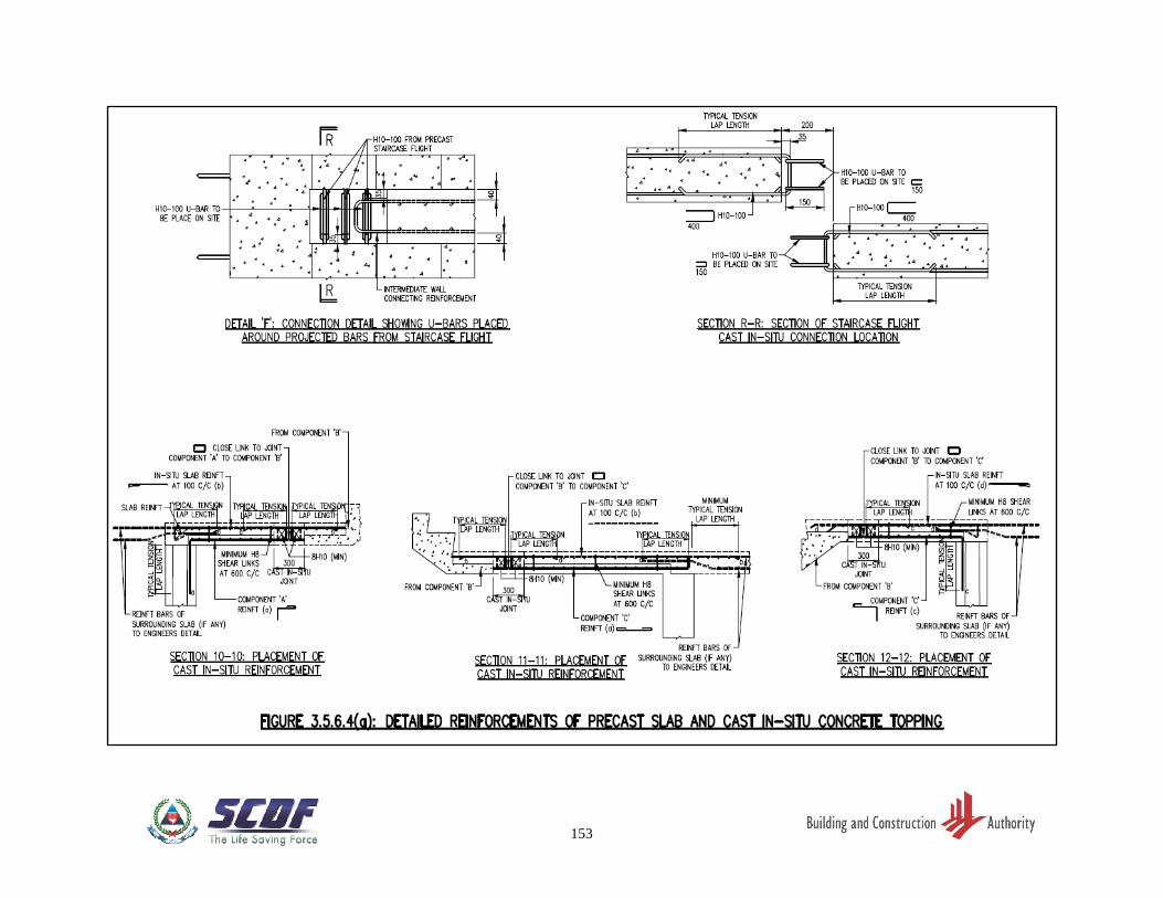
153
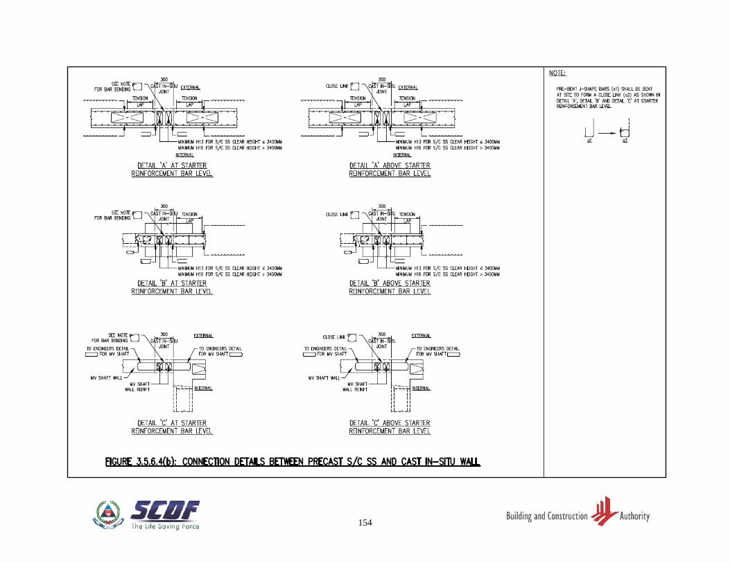
154
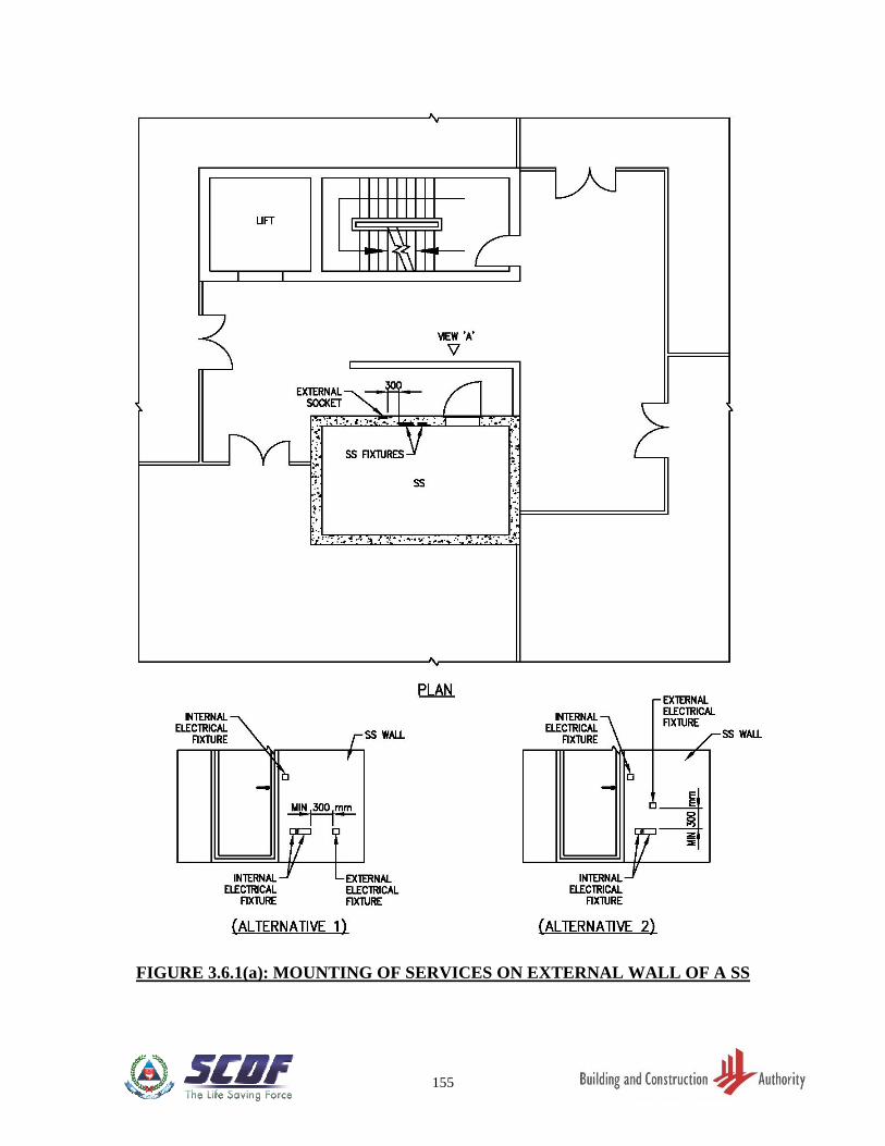
155
FIGURE 3.6.1(a): MOUNTING OF SERVICES ON EXTERNAL WALL OF A SS
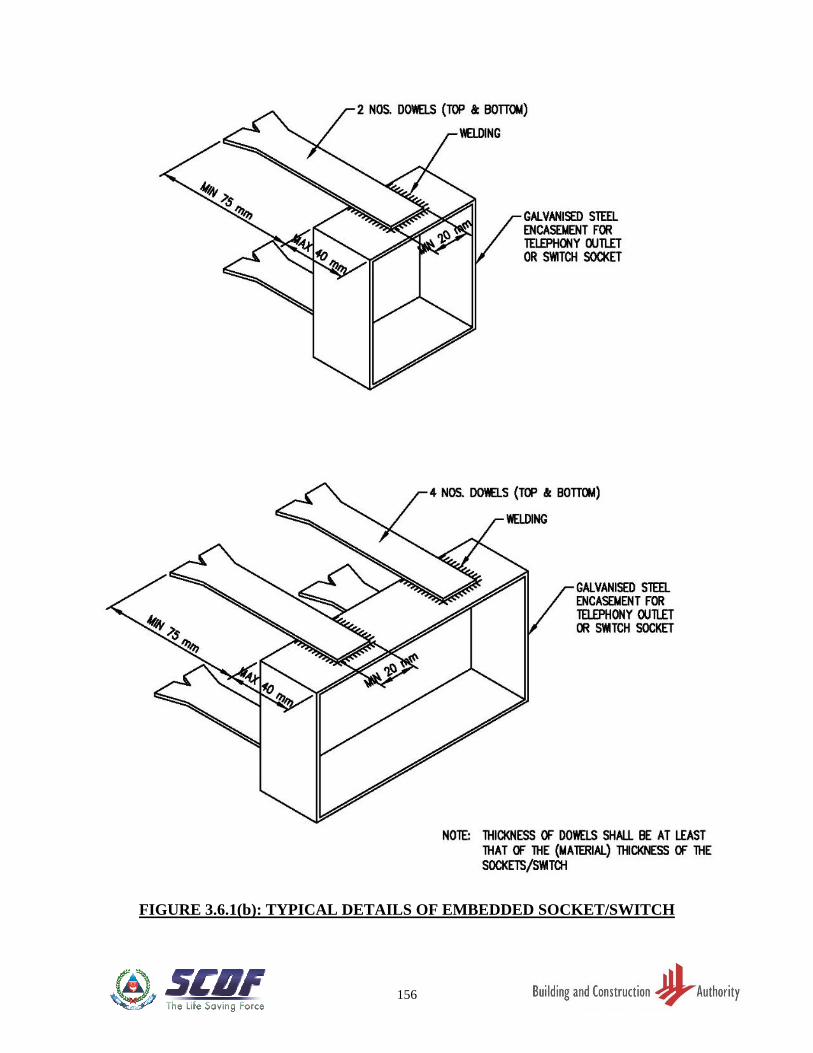
156
FIGURE 3.6.1(b): TYPICAL DETAILS OF EMBEDDED SOCKET/SWITCH
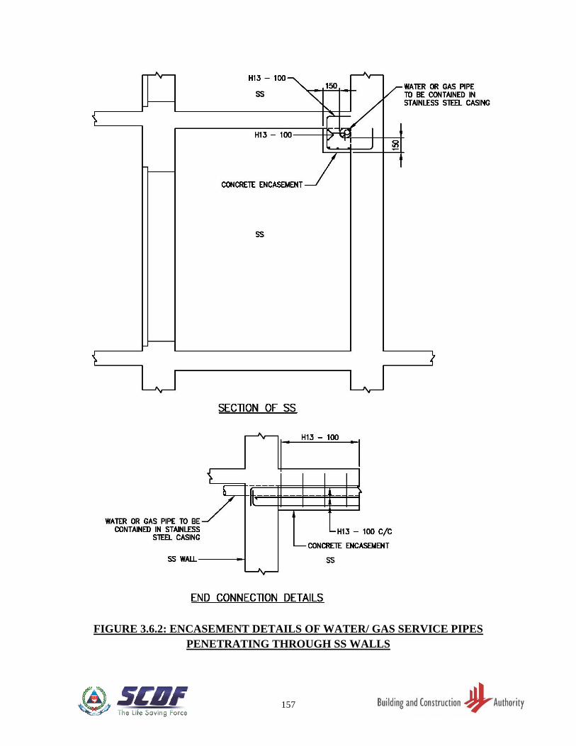
157
FIGURE 3.6.2: ENCASEMENT DETAILS OF WATER/ GAS SERVICE PIPES
PENETRATING THROUGH SS WALLS
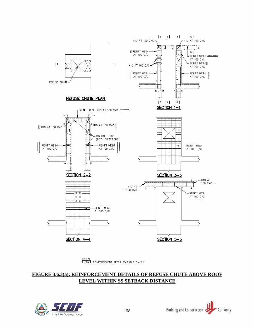
158
FIGURE 3.6.3(a): REINFORCEMENT DETAILS OF REFUSE CHUTE ABOVE ROOF
LEVEL WITHIN SS SETBACK DISTANCE
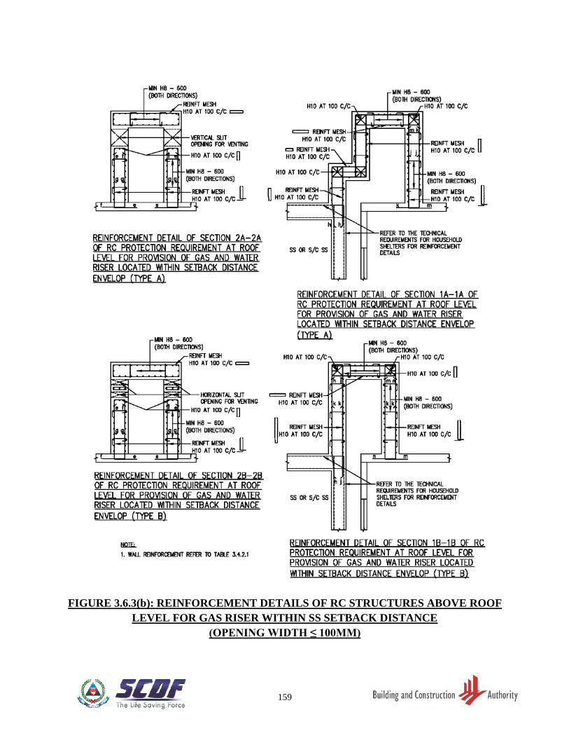
159
FIGURE 3.6.3(b): REINFORCEMENT DETAILS OF RC STRUCTURES ABOVE ROOF
LEVEL FOR GAS RISER WITHIN SS SETBACK DISTANCE
(OPENING WIDTH ≤ 100MM)
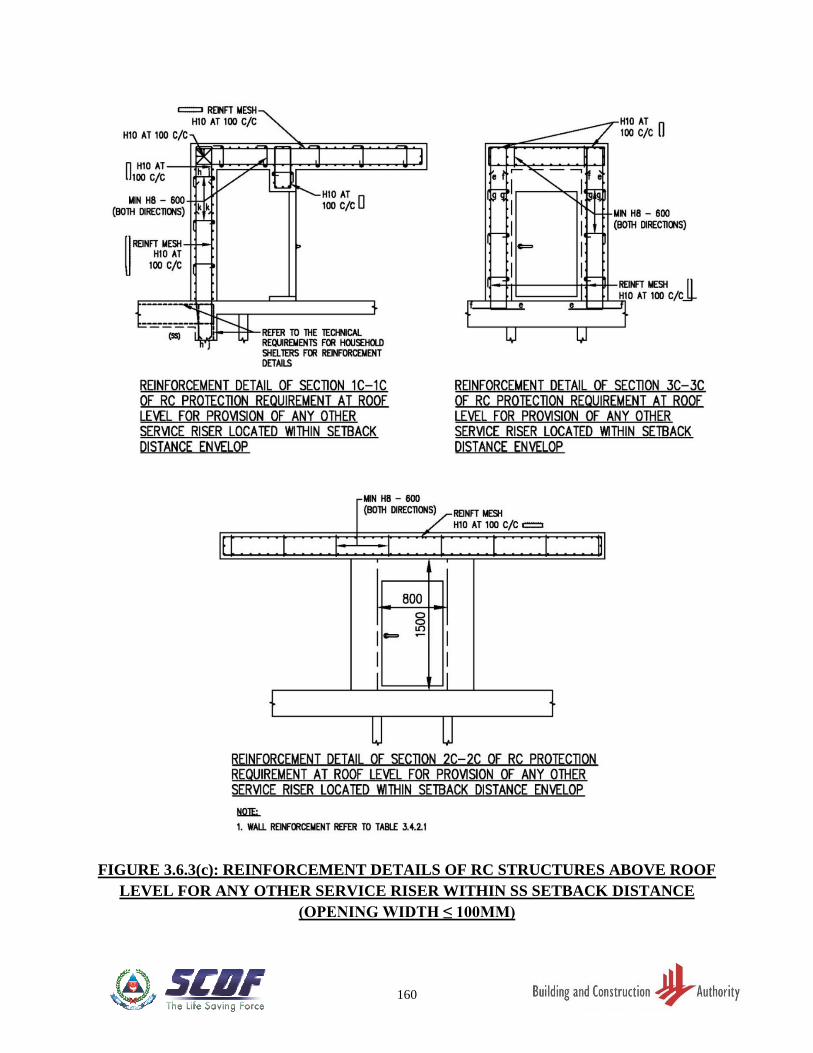
160
FIGURE 3.6.3(c): REINFORCEMENT DETAILS OF RC STRUCTURES ABOVE ROOF
LEVEL FOR ANY OTHER SERVICE RISER WITHIN SS SETBACK DISTANCE
(OPENING WIDTH ≤ 100MM)
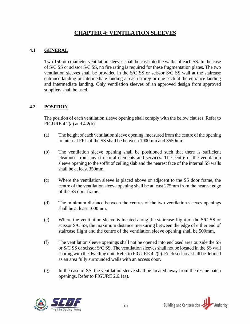
161
CHAPTER 4: VENTILATION SLEEVES
4.1 GENERAL
Two 150mm diameter ventilation sleeves shall be cast into the wall/s of each SS. In the case
of S/C SS or scissor S/C SS, no fire rating is required for these fragmentation plates. The two
ventilation sleeves shall be provided in the S/C SS or scissor S/C SS wall at the staircase
entrance landing or intermediate landing at each storey or one each at the entrance landing
and intermediate landing. Only ventilation sleeves of an approved design from approved
suppliers shall be used.
4.2 POSITION
The position of each ventilation sleeve opening shall comply with the below clauses. Refer to
FIGURE 4.2(a) and 4.2(b).
(a) The height of each ventilation sleeve opening, measured from the centre of the opening
to internal FFL of the SS shall be between 1900mm and 3550mm.
(b) The ventilation sleeve opening shall be positioned such that there is sufficient
clearance from any structural elements and services. The centre of the ventilation
sleeve opening to the soffit of ceiling slab and the nearest face of the internal SS walls
shall be at least 350mm.
(c) Where the ventilation sleeve is placed above or adjacent to the SS door frame, the
centre of the ventilation sleeve opening shall be at least 275mm from the nearest edge
of the SS door frame.
(d) The minimum distance between the centres of the two ventilation sleeves openings
shall be at least 1000mm.
(e) Where the ventilation sleeve is located along the staircase flight of the S/C SS or
scissor S/C SS, the maximum distance measuring between the edge of either end of
staircase flight and the centre of the ventilation sleeve opening shall be 500mm.
(f) The ventilation sleeve openings shall not be opened into enclosed area outside the SS
or S/C SS or scissor S/C SS. The ventilation sleeves shall not be located in the SS wall
sharing with the dwelling unit. Refer to FIGURE 4.2(c). Enclosed area shall be defined
as an area fully surrounded walls with an access door.
(g) In the case of SS, the ventilation sleeve shall be located away from the rescue hatch
openings. Refer to FIGURE 2.6.1(a).
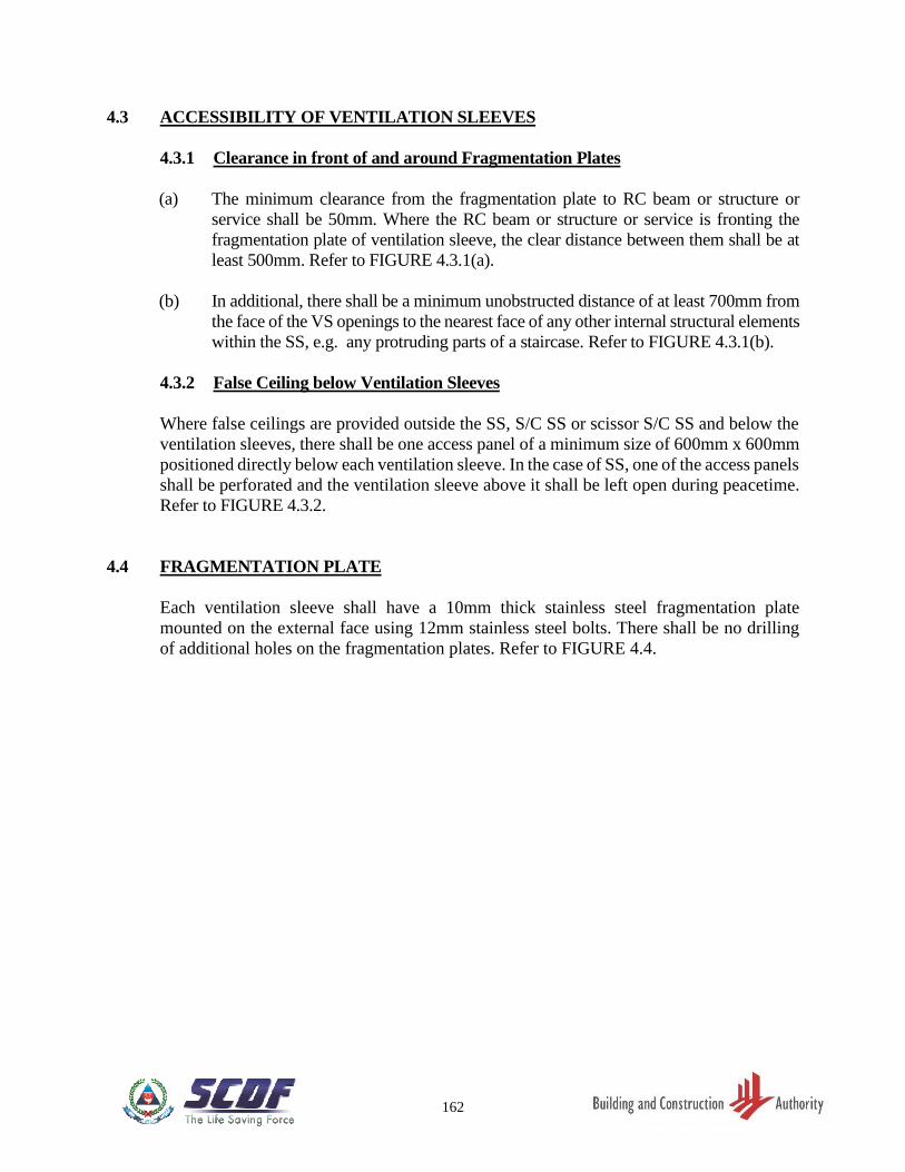
162
4.3 ACCESSIBILITY OF VENTILATION SLEEVES
4.3.1 Clearance in front of and around Fragmentation Plates
(a) The minimum clearance from the fragmentation plate to RC beam or structure or
service shall be 50mm. Where the RC beam or structure or service is fronting the
fragmentation plate of ventilation sleeve, the clear distance between them shall be at
least 500mm. Refer to FIGURE 4.3.1(a).
(b) In additional, there shall be a minimum unobstructed distance of at least 700mm from
the face of the VS openings to the nearest face of any other internal structural elements
within the SS, e.g. any protruding parts of a staircase. Refer to FIGURE 4.3.1(b).
4.3.2 False Ceiling below Ventilation Sleeves
Where false ceilings are provided outside the SS, S/C SS or scissor S/C SS and below the
ventilation sleeves, there shall be one access panel of a minimum size of 600mm x 600mm
positioned directly below each ventilation sleeve. In the case of SS, one of the access panels
shall be perforated and the ventilation sleeve above it shall be left open during peacetime.
Refer to FIGURE 4.3.2.
4.4 FRAGMENTATION PLATE
Each ventilation sleeve shall have a 10mm thick stainless steel fragmentation plate
mounted on the external face using 12mm stainless steel bolts. There shall be no drilling
of additional holes on the fragmentation plates. Refer to FIGURE 4.4.
163
FIGURE 4.2(a): POSITION OF VENTILATION SLEEVES
164
FIGURE 4.2(b): SECTIONAL VIEWS OF VENTILATION SLEEVES
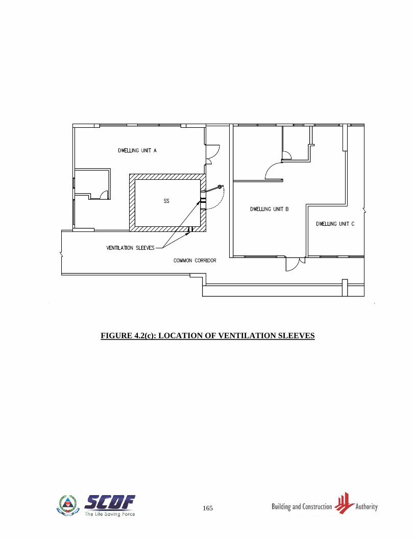
165
FIGURE 4.2(c): LOCATION OF VENTILATION SLEEVES
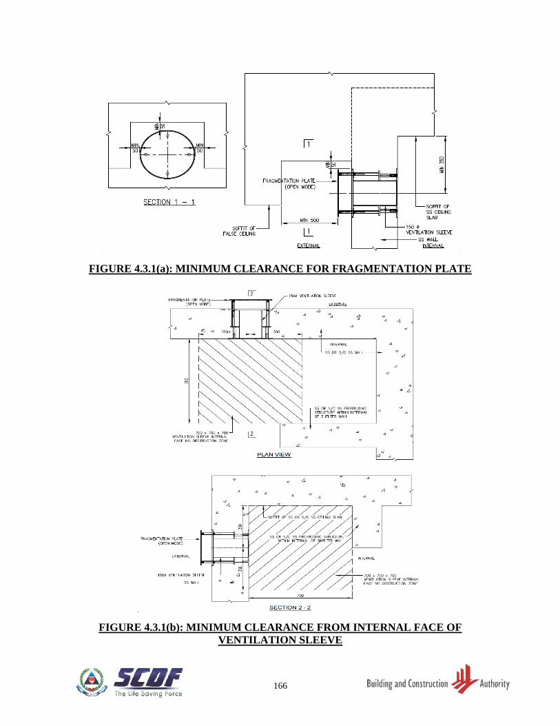
166
FIGURE 4.3.1(a): MINIMUM CLEARANCE FOR FRAGMENTATION PLATE
FIGURE 4.3.1(b): MINIMUM CLEARANCE FROM INTERNAL FACE OF
VENTILATION SLEEVE
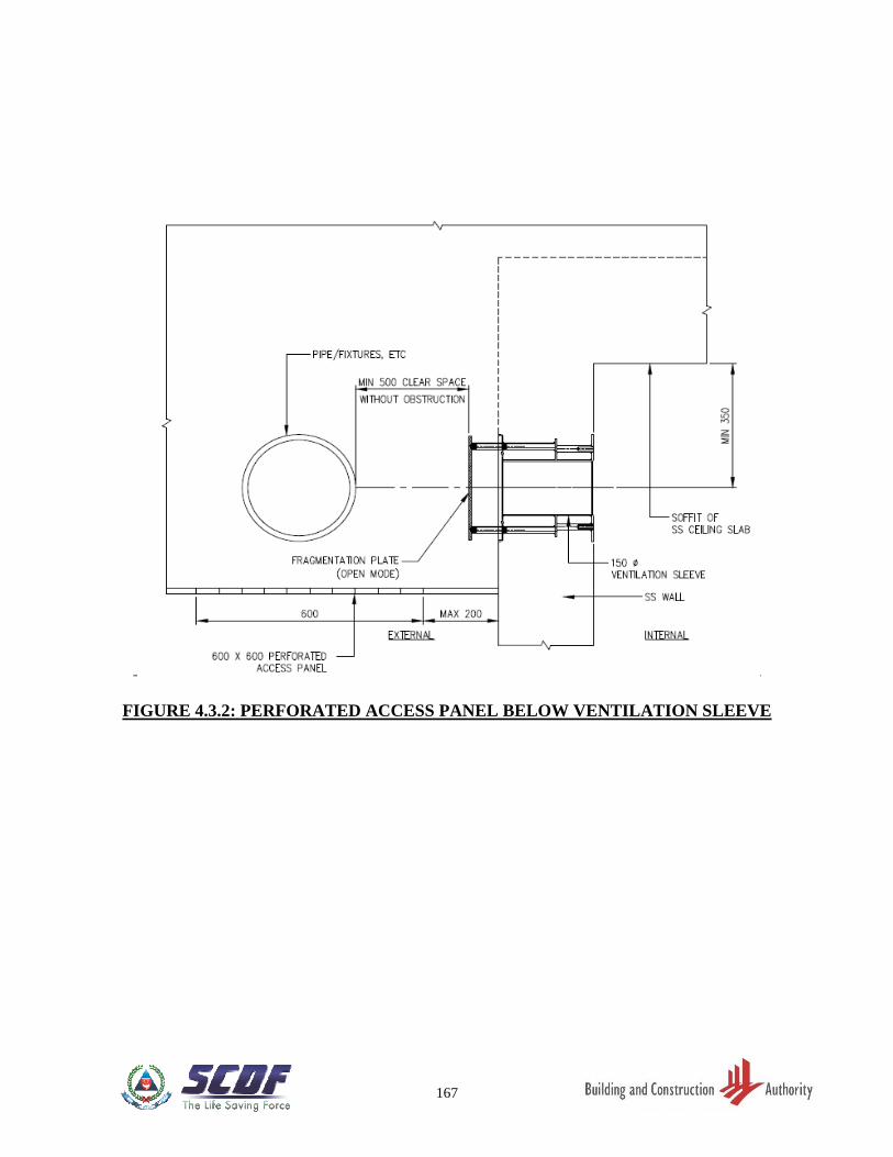
167
FIGURE 4.3.2: PERFORATED ACCESS PANEL BELOW VENTILATION SLEEVE
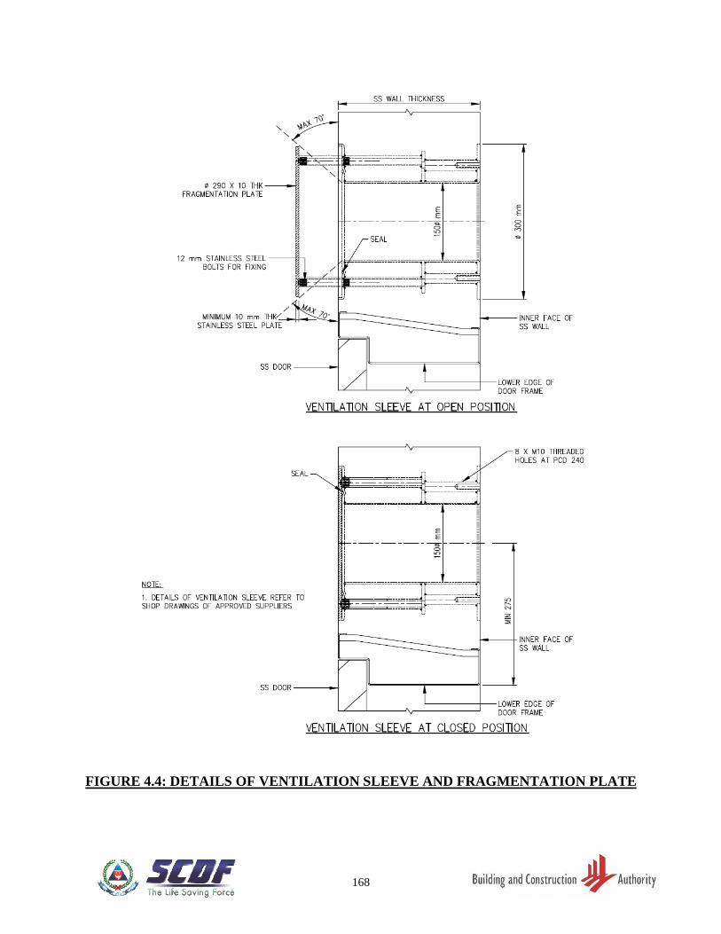
168
FIGURE 4.4: DETAILS OF VENTILATION SLEEVE AND FRAGMENTATION PLATE
169
CHAPTER 5: SS DOOR
5.1 GENERAL
The SS door shall provide an airtight closure to the SS. The SS door providing entry into the
SS from the outside shall be designed to open outwards from the SS.
SS Door frame that is cast together with the SS wall shall have single or double door rebate.
Refer to Figure 2.5.1(a) and 2.5.1(b).
5.2 APPROVED SS DOOR
Only SS doors of an approved design from an approved supplier, and which have been
certified and listed under the Product Listing Scheme with a valid Certificate of Conformity
(CoC) (as stipulated in Chapter 8 of this TR), shall be used.
5.3 REMOVABLE DOOR KERB - Applicable for S/C SS and Scissor S/C SS only
The removable SS door kerb shall be mounted on the top part of SS door frame during
peacetime. Refer to FIGURE 5.3.
5.4 SS DOOR NOTICE
Every SS door shall have a SS door notice affixed on its internal face. Refer to FIGURE
5.4(a). A sample notices for SS and S/C SS or scissor S/C SS are as shown in FIGURE
5.4(b) and 5.4 (c).
5.5 SPECIFICATIONS OF SS DOOR NOTICE
(a) Manner of Application: To be affixed on the internal SS door by pressure
sensitive and strong adhesive.
(b) Special Features: Non-brittle, rub and mar resistant, storage stability
and colour fastness under light
(c) Text, Lettering, Layout: Conform to sample notice
(d) Colours: Background is light yellow, lettering is black, sub-
headings, border and triangular logo area are red
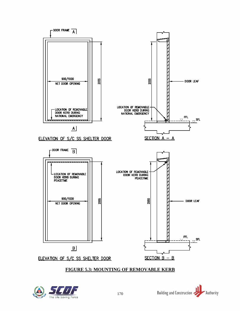
170
FIGURE 5.3: MOUNTING OF REMOVABLE KERB
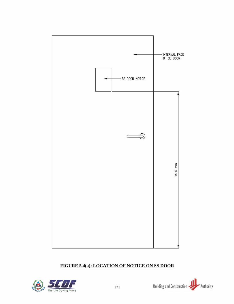
171
FIGURE 5.4(a): LOCATION OF NOTICE ON SS DOOR
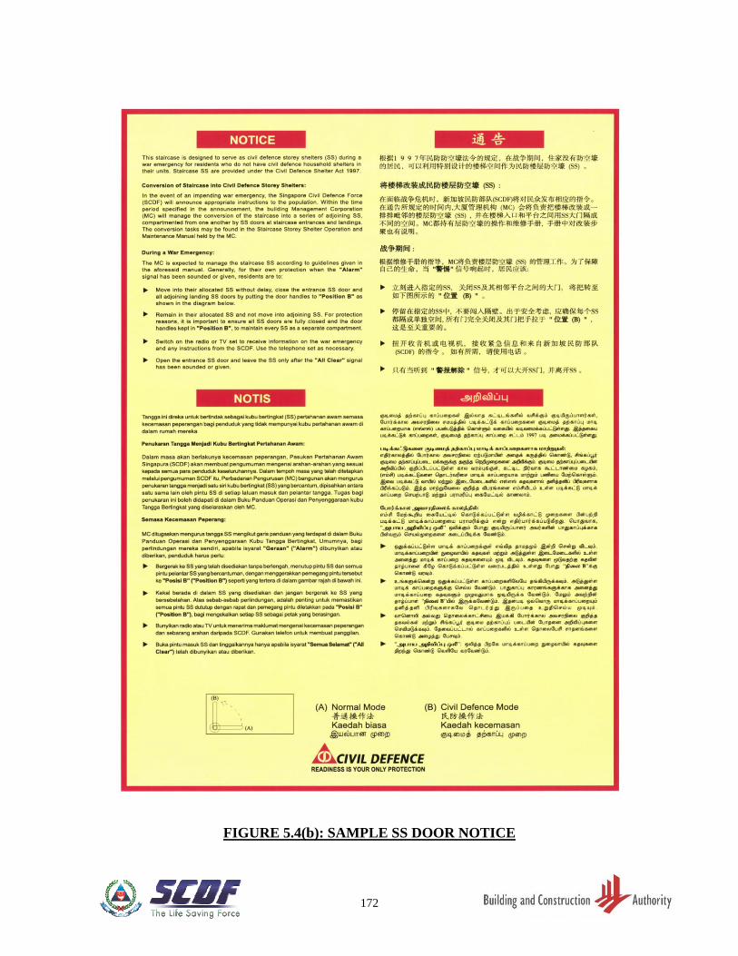
172
FIGURE 5.4(b): SAMPLE SS DOOR NOTICE
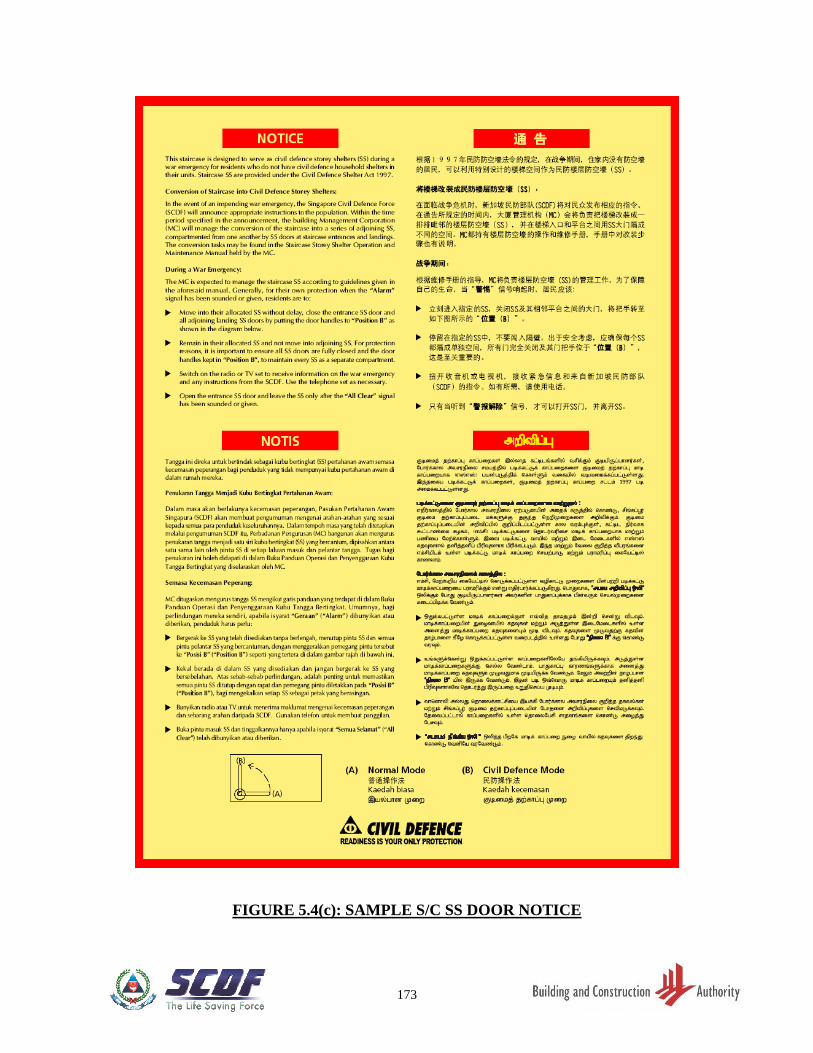
173
FIGURE 5.4(c): SAMPLE S/C SS DOOR NOTICE
174
CHAPTER 6: CONSTRUCTION AND COMMISSIONING
6.1 GENERAL
As the SS is designed to resist weapon effects, good workmanship is essential to achieve
the designed protection level.
6.2 STRUCTURAL WORKS
The following shall be observed:
(a) Only the non-removable type of form-tie (form-tie without through opening) to
secure formwork before casting of SS wall is permitted. Upon the removal of every
recessible type of plastic cones from the form-tie, the recess shall be sealed with
non-shrink grout. The use of reinforcement bar as form-tie is not permitted.
(b) To avoid bending, warping or displacement of HS door frame and honeycombing
due to inadequate compaction or leakage of cementitious grout, additional
precaution to ensure adequate compaction shall be taken while casting the concrete
near the SS door frame.
(c) All embedded items shall be placed and tightly secured in their intended location
to ensure their stability during casting. All hacking and drilling of SS tower walls,
ceiling slabs or floor slabs are not permitted without prior approval from the
Commissioner of Building Control.
(d) The exposed surfaces of SS walls and soffit of SS ceiling slabs shall be cast with
smooth concrete finish. A maximum of 2mm thick skim coat on the internal face
of the SS walls and ceiling slabs of SS is allowed.
(e) The concrete structural elements shall be adequately compacted to ensure air-
tightness. Concrete areas with segregation or honeycombing shall not be hacked
and plastered back without prior approval from the Commissioner of Building
Control.
(f) Irregularities of exposed surfaces shall not be hacked and plastered back without
prior approval from the Commissioner of Building Control.
(g) Method statement of the remedial work on structural elements, including SS door
frame, shall be approved by the Commissioner of Building Control.
175
6.3 SS DOOR
The following shall be observed:
(a) Allowing an opening in the SS wall and later erecting the SS door frame and door
leaf in this opening, followed by casting concrete around it, is not permitted.
(b) When casting the SS wall with SS door frame, a dummy door leaf of adequate
design shall be placed to ensure the stability and prevent the bending, warping or
displacement of the SS door frame during concreting.
(c) The FFL of the floor slab outside the SS shall be done such that the SS door can be
opened adequately for the peacetime use of the SS.
6.4 PEACETIME REQUIREMENT OF VENTILATION SLEEVES
For ventilation purposes during peacetime, at least 25% of total area of the two ventilation
sleeve openings in the SS walls shall be kept uncovered.
In the case of S/C SS and scissor S/C SS, all ventilation sleeve openings shall be fully
closed.
6.5 COMMISSIONING REQUIREMENTS
All electrical and communication fixtures such as switch and lighting point, electrical
socket outlets, communication line for telephony outlet, including SS door notice, rescue
hatch and cat-ladder (both applicable to SS), blast hatch (applicable to S/C SS or scissor
S/C SS) shall be provided inside the completed SS. The service conduits with electrical
cables serving the SS shall be provided prior to commissioning.
A SS is considered commissioned only if the SS passes all the following tests in one
inspection:
(a) Light penetration test of SS door - an acceptable test method to check on light
penetration into the SS is to use torchlight from the exterior of SS door. The test is
considered to have passed if no light could be seen from the inside of SS.
(b) Chalk mark test on the SS door - an acceptable test method is to apply chalk to the
part of the door frame where the door seal will come into contact with when the
door is closed. The test is considered to have passed if there is an unbroken and
uniform transfer of the chalk markings onto the door seal when the door is closed
and re-opened.
176
(c) Air-tightness test of the SS - an acceptable test method is to pressurise the SS and
measure the rate of pressure drop or the pressure difference between the interior
and exterior of the SS. The *pressure gauge can be used for the test. The SS is
pressurised by pumping air into the SS such that there is a pressure difference of
250 Pa* between inside and outside of SS. The SS is considered to have passed the
test if the pressure gauge shows more than or equal to 50 Pa after 45 seconds.
Except in the case of S/C SS or scissor S/C SS, the ventilation sleeves of the SS, which have been
closed for the commissioning tests, shall be opened after the tests to comply with Clause 6.4 for
ventilation during peacetime.
* The pressure gauge used should have a dial size with a scale of 0 to 50mm or 0 to 500 Pa. (Note:
1 mm = 10 Pa).
177
CHAPTER 7: PERMITTED AND NOT PERMITTED WORKS IN
SS TOWER
7.1 GENERAL
Any repair or alteration or renovation works, which are likely to weaken or damage any
structural elements of the SS or NS, is not permitted.
7.2 PERMITTED AND NOT PERMITTED WORKS
7.2.1 Permitted Works in SS
(a) Laying of floor tiles bonded to wet cement mortar. The total thickness of floor
finishes and screed is not to exceed 50mm.
(b) Laying of floor skirting tiles (up to a maximum of 100mm high) by bonding them
with wet cement mortar to SS walls
(c) Laying of vinyl or linoleum flooring is permitted in SS but not permitted in S/C SS
or scissor S/C SS.
(d) Applying splatter dash or equivalent to the external face of SS walls only to provide
rough surface for feature wall panels or wall tiles installation.
(e) Painting of walls, ceiling or door. In the case of SS door, owners shall not cover up
or paint over the SS door notice (See Clause 5.3), locking bolts or door seal. The
old paint coat on door and door frame is to be removed prior to repainting to avoid
increase in paint thickness resulting in difficulty in closing and opening of the door.
The new paint coat must be dried up completely before closing the door as wet or
damp paint will cause the door/rubber gasket to stick onto the door frame when
opening the closed door.
(f) Painting on only the exterior face of the 10mm fragmentation stainless steel plate
of the ventilation sleeves.
(g) Drilling into internal face of SS walls and ceiling slabs to a depth of not more than
50mm to affix inserts and removable screws is permitted in SS but not permitted in
S/C SS or scissor S/C SS. Fixtures such as pictures, posters, cabinets or shelves
mounted on the internal face of SS walls will have to be removed by the owners
within 48 hours upon notification. There is no restriction to the diameter of the non-
metallic insert as long as it does not exceed 50mm in length. It is the owner’s
responsibility to ensure that the strength of the insert is adequately provided for the
intended purpose.
178
(h) Power driven nails are allowed only on external face of the SS walls to facilitate
flexibility in mounting of features/fixtures by owners.
(i) Removal of the fragmentation plates (Clause 4.4) covering the ventilation openings
is permitted for SS but not permitted in S/C SS or scissor S/C SS. The removal of
fragmentation for SS shall comply with the following conditions:
(i) The plates (after removal) shall be securely mounted with removable screws
on non-metallic inserts not exceeding 50mm deep on one of the internal face
of SS walls.
(ii) After the removal of plates, the bolts and nuts shall be installed back to their
original positions on the ventilation sleeves.
(iii) Closing or covering up of ventilation openings by removable aesthetic or
architectural finishes is allowed, provided that at least 25% of the total area
of the two openings shall be left uncovered for ventilation purposes during
peacetime.
(j) The minimum clearance from the fragmentation plate to RC beam or structure or
service shall be 50mm. Where RC beam or structure or service is fronting the
fragmentation plate of ventilation sleeve, the clear distance between them shall be
at least 500mm. Refer to FIGURE 4.3.1(a).
(k) Where false ceilings, which are provided on the exterior of the SS, are to be installed
at a level below the ventilation sleeves, there shall be one perforated access panel
of a minimum size of 600mm x 600mm to be provided directly below each
ventilation sleeve. Refer to FIGURE 4.3.2.
7.2.2 Not Permitted Works in SS
(a) Laying of wall tiles or spray of rock tone finish, cement sand finish and gypsum
plastering on the internal faces of SS walls.
(b) Laying of floor tiles using adhesive materials.
(c) Laying of 2nd layer of tiles on floor or skirting tiles.
(d) Installation of cornices within the SS.
(e) Installation works with fixings using power driving nails into the internal SS walls
(f) Tampering with, removing or covering up of the SS door notice. The SS door notice
provides important information to the occupants on the use of the SS.
179
(g) Hacking and drilling of SS walls, floor slabs, and ceiling slabs without prior
approval from the Commissioner of Building Control, other than drilling permitted
in Clause 7.2.1(g) and 7.2.1(h) and shall not exceed 50mm.
(h) Hacking to both internal and external face of the SS walls to form key for tiling.
(i) Hacking on external face of SS wall for mounting of feature wall panels or wall
tiles installation.
(j) Modifying, changing, removing or tampering of SS door without prior approval
from the Commissioner of Building Control.
(k) Modifying, altering or tampering with any part of the ventilation openings, plates
and the mounting devices such as bolts and nuts without prior approval from the
Commissioner of Building Control.
(l) Painting to the interior face of the 10mm fragmentation stainless steel plate of the
ventilation sleeves, the ventilation sleeves, “O” ring rubber gaskets and the four or
eight numbers of stainless steel bolts which hold the steel plate to the sleeves.
7.2.3 Not Permitted Works in NS
(a) Hacking and drilling of NS walls, floor slabs, and ceiling slabs without prior
approval from the Commissioner of Building Control, other than drilling into NS
walls and ceiling slab to affix removable screws on inserts, provided the depth of
the insert shall not exceed 50mm.
(b) Modifying, changing, removing or tampering of SS door without prior approval
from the Commissioner of Building Control.
180
CHAPTER 8: REGULATED SHELTER PRODUCTS
8.1 GENERAL
This Chapter stipulates requirements relating to the certification of shelter
products regulated by SCDF under the Product Listing Scheme. These
requirements include the acceptable test standards, certification scheme and
surveillance regime for the regulated shelter product (refer to Table 8.1).
For the full list of requirements, this Chapter shall be read in conjunction with
the Civil Defence Shelter Act (CDSA) and CT 23 of SAC’s “Criteria for
Product Certification Bodies (Regulated Shelter Products)”.
8.2 DEFINITIONS
8.2.1 Accredited Certification Body
“Accredited certification body” (CB) refers to a body corporate or corporation
incorporated or constituted under the law of Singapore, accredited under the
Singapore Accreditation Council (SAC)’s certification body accreditation
scheme administered by the Enterprise Singapore Board.
8.2.2 Accredited Laboratory
“Accredited laboratory” refers to a body corporate or corporation providing
laboratory testing services, which is accredited under SAC’s laboratory
accreditation scheme administered by the Enterprise Singapore Board, or
recognised under the International Laboratory Accreditation Cooperation
(ILAC) Mutual Recognition Agreement/Arrangement between Singapore and
other countries.
8.2.3 Certificate of Conformity (CoC)
“Certificate of Conformity” refers to a certificate issued by CBs for a regulated
shelter product that meets product testing standards and certification
requirements. These certified products shall be recorded in a product directory
on the CB’s website for reference and verification of the CoCs’ validity.
8.2.4 Local Representative
“Local representative” refers to the Singapore -registered agent/partner
appointed by a foreign CoC holder, in order for its certified regulated shelter
products to be supplied in Singapore.
181
8.2.5 Mutual Recognition Arrangement/Agreement (MRA)
“Mutual Recognition Arrangement” or “Mutual Recognition Agreement” refers
to the arrangements signed between SAC and other international assessment
bodies, which mutually recognise reports and certificates issued by an
accredited Conformity Assessment Body (CAB) as equivalent to their own
accreditation requirements.
8.2.6 Product Listing Scheme (PLS)
“Product listing scheme” refers to the third -party certification scheme
administered by SCDF for regulated shelter products.
8.2.7 Scheme Type 5 (Scheme 5)
“Scheme Type 5” consists of type testing and factory inspection during initial
certification, and ongoing assessment of the entire quality management system,
including auditing the production process and management system.
Surveillance testing of the product is done either from the market or at the
point of production, or both, to check that items produced fulfil the specified
requirements.
8.2.8 Serial Label
“Serial label” refers to a certification label issued by CBs, with unique serial
numbers. These are affixed to certified regulated shelter products, such as SS
doors (refer to Table 8.1). Such labels allow tracing of these products to their
corresponding CoC and the specific installation location of each product.
8.2.9 Surveillance Window
"Surveillance window”, also known as “surveillance cycle”, refers to the
period of 12 or 36 months (as stipulated in Table 8.1), starting from the date
that a CoC is issued in relation to a regulated shelter product, and every
subsequent period of 12 or 36 months or shorter, if the CoC expires, or is
terminated or withdrawn. Products may be subjected to post -certification
testing and/or inspection, based on the survei llance window.
8.2.10 Suspension of CoC
“Suspension of CoC” refers to the temporary invalidation of a CoC by a CB
under circumstances not limited to the following:
(a) Non-compliance to any component of the surveillance regime .
182
(b) Products are suspected to not meet shelter requirements but are still in
the process of being tested/investigated.
(c) CoC holder breaching the CB’s terms and conditions (including non -
payment of fees).
8.2.11 Termination of CoC
“Termination of CoC” refers to the cancel lation of a CoC, either on the request
of the CoC holder before its expiry, or due to reasons not related to shelter
requirements. Examples of such circumstances include:
(a) CoC holder ceases to supply the product due to business considerations
(e.g. shutting down of business, liquidation).
(b) CoC holder fails to take adequate rectification measures within the
given timeframe, despite being suspended for a breach in the CB’s
terms and conditions (including non-payment of fees).
8.2.12 Type Testing
“Type testing”, also known as prototype testing, refers to testing of a product
according to the test standard(s) and specification(s) for that product for the
application of CoC, as specified in Table 8.2.
8.2.13 Withdrawal of CoC
“Withdrawal of CoC” refers to the cancellation of a CoC by the CB under
circumstances not limited to the following:
(a) Non-compliance with the requirements of the Product Listing Scheme,
including:
(i) Regulated shelter product that is supplied to the industry differs
from the prototype described in the CoC and laboratory test
report.
(ii) Misuse of certification mark, logo and certificates .
(iii) Supply of products from a factory which differs from the factory
declared during the CoC application.
(b) Failure to take adequate rectification measures within the given
timeframe, despite being suspended for a shelter-related non-
compliance.
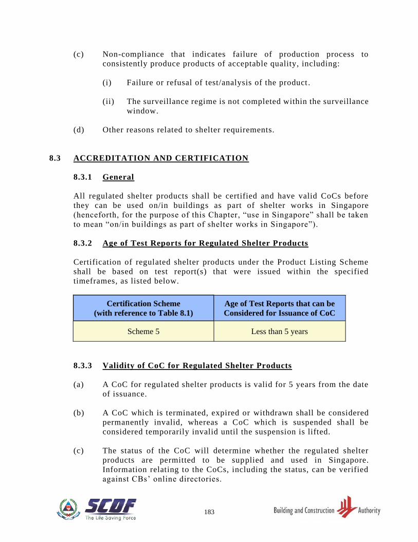
183
(c) Non-compliance that indicates failure of production process to
consistently produce products of acceptable quality, including:
(i) Failure or refusal of test/analysis of the product .
(ii) The surveillance regime is not completed within the surveillance
window.
(d) Other reasons related to shelter requirements.
8.3 ACCREDITATION AND CERTIFICATION
8.3.1 General
All regulated shelter products shall be certified and have valid CoCs before
they can be used on/in buildings as part of shelter works in Singapore
(henceforth, for the purpose of this Chapter, “use in Singapore” shall be taken
to mean “on/in buildings as part of shelter works in Singapore”).
8.3.2 Age of Test Reports for Regulated Shelter Products
Certification of regulated shelter products under the Product Listing Scheme
shall be based on test report(s) that were issued within the specified
timeframes, as listed below.
Certification Scheme
(with reference to Table 8.1)
Age of Test Reports that can be
Considered for Issuance of CoC
Scheme 5 Less than 5 years
8.3.3 Validity of CoC for Regulated Shelter Products
(a) A CoC for regulated shelter products is valid for 5 years from the date
of issuance.
(b) A CoC which is terminated, expired or withdrawn shall be considered
permanently invalid, whereas a CoC which is suspended shall be
considered temporarily invalid until the suspension is lifted.
(c) The status of the CoC will determine whether the regulated shelter
products are permitted to be supplied and used in Singapore.
Information relating to the CoCs, including the status, can be verified
against CBs’ online directories.
184
(i) For products with valid CoCs at the date of delivery to the
project site, i.e. not suspended, terminated, expired or
withdrawn, these are permitted to be used in Singapore.
(ii) For products with CoCs that are not valid on the date of delivery
to the project site, i.e. suspended, terminated, expired or
withdrawn, usage of these products in Singapore is prohibited.
(iii) Notwithstanding (1), for products with CoCs that were valid on
the date of delivery, but are subsequently withdrawn, usage of
the affected batches of such products in Singapore is subject to
further assessment and investigation by SCDF and/or the CBs.
(iv) Notwithstanding (1), for products with CoCs that were valid on
the date of delivery, but are subsequently suspended for shelter -
related reasons, e.g. pending investigation, it is not
recommended that such products be used, as the investigation
may show that the products are non-compliant and cannot be
used (e.g. products that have been installed will need to be
replaced/removed).
(v) CBs shall not allow the termination of a CoC which is suspended
for shelter-related reasons, or which is under investigation by
SCDF.
8.3.4 Accreditation Requirements
(a) Regulated shelter products used in shelter works shall be certified by a
local certification body accredited by SAC.
(b) Regulated shelter products shall be accompanied by test reports from
testing laboratories accredited by SAC or recognised by SAC via the
International Laboratory Accreditation Cooperation (ILAC) MRA.
(c) Any new CB participating in the PLS shall notify SCDF, in writing, of
its accreditation by SAC, and submit its Certificate of Accreditation
and Schedule issued by SAC for SCDF’s record. SCDF may request for
additional information from the CB.
8.3.5 Certification Requirements
(a) General Requirements
CoCs issued for products intended for use in Singapore shall bear
SAC’s accreditation mark.
185
(b) Information Submitted for New CoC Applications
The following information, at minimum, shall be submitted to a CB for
application of a CoC. Where the information/documents are not
provided in English, an official English translation, endorsed by a
Notary Public, shall also be provided:
(i) CoC applicant details, including:
(a) Unique Entity Number (UEN) issued by the Accounting
and Corporate Regulatory Authority (ACRA), or foreign
equivalent, where applicable.
(b) Full names of the company directors, or equivalent .
(c) Name, address, contact number and email address of the
company.
(d) Where the applicant is a foreign company, the details of
the appointed local representative, for parts (1)(a) through
(1)(c) shall also be included.
(e) Proof of partnership between the local representative and
foreign CoC holder.
(ii) Manufacturer’s details, for all the manufacturing plants of
components of the regulated shelter product affecting shelter -
related requirements, including:
(a) Country, name, address, contact number and email address
of the manufacturer.
(iii) Certification scheme details, including:
(a) Product category as classified under Table 8.1.
(b) Certification scheme, according to Clause 8.2.7.
(iv) Product details, including:
(a) Brand and model, as determined by the manufacturer .
(b) Density and weight, where applicable, measured in kg/m 3
and kg, respectively.
(c) Dimensions, where applicable, measured in mm.
186
(d) Latest product catalogue stipulating the specifications and
user instructions.
(v) Details of type tests, including:
(a) The reference number of the test report .
(b) Test standards (including version of the test standard, i.e.
year) which the product is tested to.
(c) Documents Submitted for New CoC Applications
The following documents shall also be submitted for CoC applications:
(i) Test reports, including the full type test reports and other test(s)
required by the CB (e.g. material tests), which shall be:
(a) In full colour.
(b) Bear the brand and model of the regulated shelter product.
(ii) For each test report, the credentials of the accredited laboratory
which issued the test report, including:
(a) Documentation that the test laboratory is accredited by
SAC or recognised by SAC via ILAC MRA.
(b) The accreditation scope indicating the test laboratory is
accredited to perform such a test.
(d) Information and Documents Submitted for Renewal of CoC
CoC holders shall submit the information stipulated in Clause
8.3.5b.(1) and (2) and provide the date of issue of the very first CoC
that had been issued for the product (i.e. “Original date of issue”). The
CB shall make an assessment on whether there is a need to submit
information stipulated in Clause 8.3.5b.(3) – (5), as well as documents
stipulated in Clause 8.3.5c.(1) and (2). CB may require submission of
any further information/documents as it deems fit.
187
8.4 SERIAL LABELS
8.4.1 Traceability of Certified Shelter Products
(a) Serial labels affixed to certified shelter products shall be water -proof
and tamper-proof, and shall include a Quick Response (QR) code that
stores the following information on an online database, which can be
read by scanning the QR code:
(i) CoC holder company name.
(ii) CoC holder ACRA UEN.
(iii) CoC reference number.
(iv) Brief product description.
(v) Exact location, including unit number, where applicable, where
the regulated shelter product is installed .
(vi) The status of the label (“valid” or “void”) .
Note: The status of the label will be ‘void’ if SCDF detects discrepancies
relating to the use of serial labels and digitally voided the serial label.
(b) The following information shall be printed on the label itself:
(i) Product category.
(ii) Unique serial number.
(iii) CB’s logo or CB’s certification mark.
8.4.2 Replacement of Serial Labels
(a) In the event that the serial labels are missing or damaged, a police
report shall be lodged before replacement labels can be obtained from
the CBs. A copy of this report shall be furnished to the CB, when
requesting for replacement of labels.
(b) An investigation by the CB shall also be conducted on the nature of the
damage and/or loss, with the findings reported to SCDF for
accountability.
Exemption: If labels are returned to the CB with the serial numbers still legible,
a police report is not required.
188
8.5 REQUIREMENTS AND RESPONSIBILITIES FOR QUALIFIED
PERSONS
Where shelter works involve the use of regulated shelter products, Qualified
Persons shall carry out inspections of the shelter products, including but not
limited to, the following:
(a) Verify that the regulated shelter product(s) have valid CoC(s) and that
the CoC(s) match exactly with the products used .
(b) Verify that the regulated shelter product(s) are af fixed with serial
labels, if said products are stipulated to have labels in Table 8.1 .
(c) Where there are serial labels, verify that the serial label affixed on the
product, are accurate and match exactly with the product.
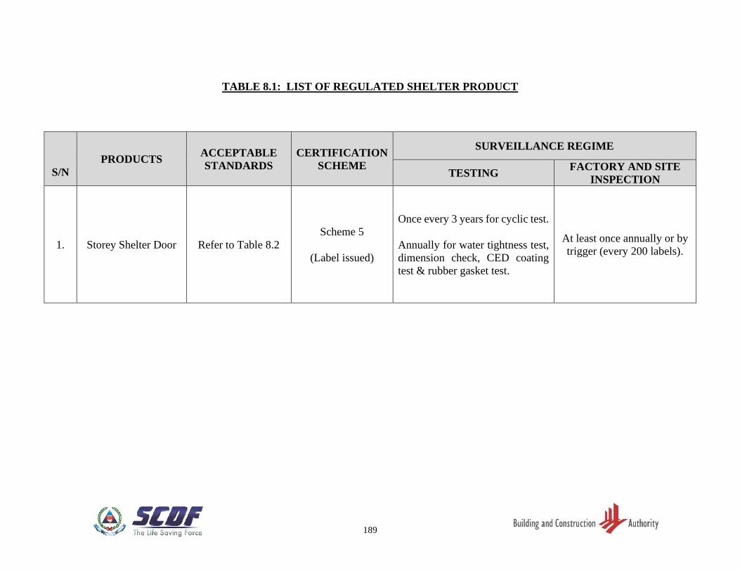
189
TABLE 8.1: LIST OF REGULATED SHELTER PRODUCT
S/N
PRODUCTS ACCEPTABLE
STANDARDS
CERTIFICATION
SCHEME
SURVEILLANCE REGIME
TESTING FACTORY AND SITE
INSPECTION
1. Storey Shelter Door Refer to Table 8.2
Scheme 5
(Label issued)
Once every 3 years for cyclic test.
Annually for water tightness test,
dimension check, CED coating
test & rubber gasket test.
At least once annually or by
trigger (every 200 labels).
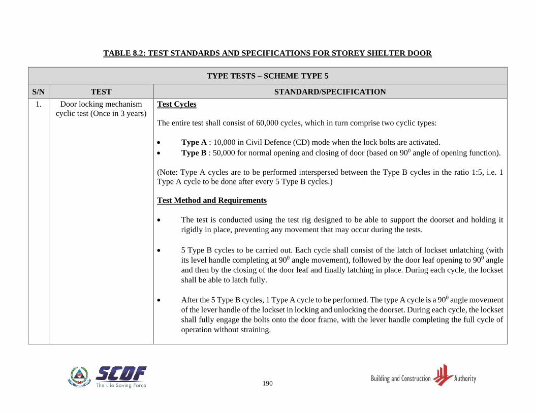
190
TABLE 8.2: TEST STANDARDS AND SPECIFICATIONS FOR STOREY SHELTER DOOR
TYPE TESTS – SCHEME TYPE 5
S/N TEST STANDARD/SPECIFICATION
1. Door locking mechanism
cyclic test (Once in 3 years)
Test Cycles
The entire test shall consist of 60,000 cycles, which in turn comprise two cyclic types:
• Type A : 10,000 in Civil Defence (CD) mode when the lock bolts are activated.
• Type B : 50,000 for normal opening and closing of door (based on 900 angle of opening function).
(Note: Type A cycles are to be performed interspersed between the Type B cycles in the ratio 1:5, i.e. 1
Type A cycle to be done after every 5 Type B cycles.)
Test Method and Requirements
• The test is conducted using the test rig designed to be able to support the doorset and holding it
rigidly in place, preventing any movement that may occur during the tests.
• 5 Type B cycles to be carried out. Each cycle shall consist of the latch of lockset unlatching (with
its level handle completing at 900 angle movement), followed by the door leaf opening to 900 angle
and then by the closing of the door leaf and finally latching in place. During each cycle, the lockset
shall be able to latch fully.
• After the 5 Type B cycles, 1 Type A cycle to be performed. The type A cycle is a 900 angle movement
of the lever handle of the lockset in locking and unlocking the doorset. During each cycle, the lockset
shall fully engage the bolts onto the door frame, with the lever handle completing the full cycle of
operation without straining.
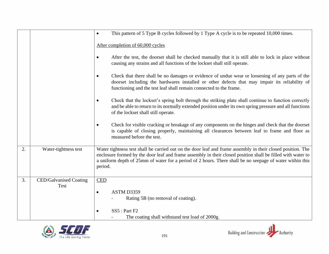
191
• This pattern of 5 Type B cycles followed by 1 Type A cycle is to be repeated 10,000 times.
After completion of 60,000 cycles
• After the test, the doorset shall be checked manually that it is still able to lock in place without
causing any strains and all functions of the lockset shall still operate.
• Check that there shall be no damages or evidence of undue wear or loosening of any parts of the
doorset including the hardwares installed or other defects that may impair its reliability of
functioning and the test leaf shall remain connected to the frame.
• Check that the lockset’s spring bolt through the striking plate shall continue to function correctly
and be able to return to its normally extended position under its own spring pressure and all functions
of the lockset shall still operate.
• Check for visible cracking or breakage of any components on the hinges and check that the doorset
is capable of closing properly, maintaining all clearances between leaf to frame and floor as
measured before the test.
2. Water-tightness test Water tightness test shall be carried out on the door leaf and frame assembly in their closed position. The
enclosure formed by the door leaf and frame assembly in their closed position shall be filled with water to
a uniform depth of 25mm of water for a period of 2 hours. There shall be no seepage of water within this
period.
3. CED/Galvanised Coating
Test
CED
• ASTM D3359
- Rating 5B (no removal of coating).
• SS5 : Part F2
- The coating shall withstand test load of 2000g.
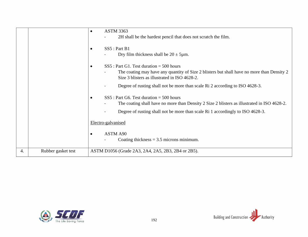
192
• ASTM 3363
- 2H shall be the hardest pencil that does not scratch the film.
• SS5 : Part B1
- Dry film thickness shall be 20 ± 5µm.
• SS5 : Part G1. Test duration = 500 hours
- The coating may have any quantity of Size 2 blisters but shall have no more than Density 2
Size 3 blisters as illustrated in ISO 4628-2.
- Degree of rusting shall not be more than scale Ri 2 according to ISO 4628-3.
• SS5 : Part G6. Test duration = 500 hours
- The coating shall have no more than Density 2 Size 2 blisters as illustrated in ISO 4628-2.
- Degree of rusting shall not be more than scale Ri 1 accordingly to ISO 4628-3.
Electro-galvanised
• ASTM A90
- Coating thickness = 3.5 microns minimum.
4. Rubber gasket test ASTM D1056 (Grade 2A3, 2A4, 2A5, 2B3, 2B4 or 2B5).
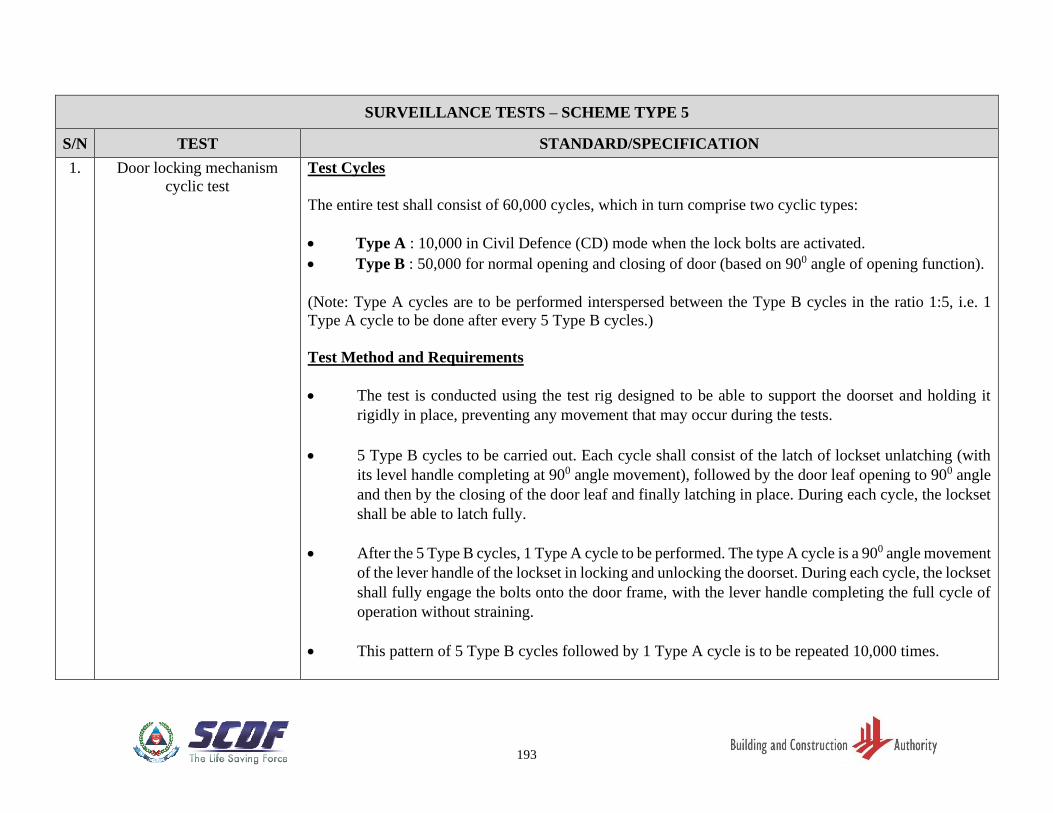
193
SURVEILLANCE TESTS – SCHEME TYPE 5
S/N TEST STANDARD/SPECIFICATION
1. Door locking mechanism
cyclic test
Test Cycles
The entire test shall consist of 60,000 cycles, which in turn comprise two cyclic types:
• Type A : 10,000 in Civil Defence (CD) mode when the lock bolts are activated.
• Type B : 50,000 for normal opening and closing of door (based on 900 angle of opening function).
(Note: Type A cycles are to be performed interspersed between the Type B cycles in the ratio 1:5, i.e. 1
Type A cycle to be done after every 5 Type B cycles.)
Test Method and Requirements
• The test is conducted using the test rig designed to be able to support the doorset and holding it
rigidly in place, preventing any movement that may occur during the tests.
• 5 Type B cycles to be carried out. Each cycle shall consist of the latch of lockset unlatching (with
its level handle completing at 900 angle movement), followed by the door leaf opening to 900 angle
and then by the closing of the door leaf and finally latching in place. During each cycle, the lockset
shall be able to latch fully.
• After the 5 Type B cycles, 1 Type A cycle to be performed. The type A cycle is a 900 angle movement
of the lever handle of the lockset in locking and unlocking the doorset. During each cycle, the lockset
shall fully engage the bolts onto the door frame, with the lever handle completing the full cycle of
operation without straining.
• This pattern of 5 Type B cycles followed by 1 Type A cycle is to be repeated 10,000 times.
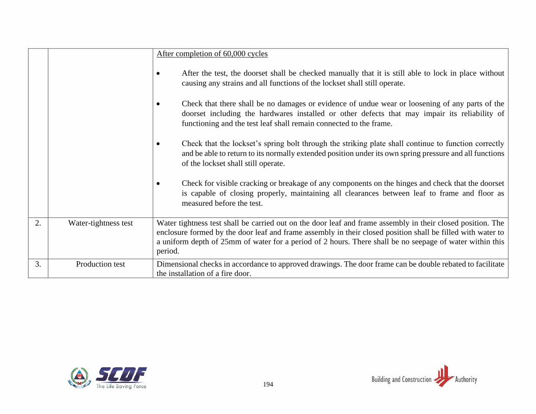
194
After completion of 60,000 cycles
• After the test, the doorset shall be checked manually that it is still able to lock in place without
causing any strains and all functions of the lockset shall still operate.
• Check that there shall be no damages or evidence of undue wear or loosening of any parts of the
doorset including the hardwares installed or other defects that may impair its reliability of
functioning and the test leaf shall remain connected to the frame.
• Check that the lockset’s spring bolt through the striking plate shall continue to function correctly
and be able to return to its normally extended position under its own spring pressure and all functions
of the lockset shall still operate.
• Check for visible cracking or breakage of any components on the hinges and check that the doorset
is capable of closing properly, maintaining all clearances between leaf to frame and floor as
measured before the test.
2. Water-tightness test Water tightness test shall be carried out on the door leaf and frame assembly in their closed position. The
enclosure formed by the door leaf and frame assembly in their closed position shall be filled with water to
a uniform depth of 25mm of water for a period of 2 hours. There shall be no seepage of water within this
period.
3. Production test Dimensional checks in accordance to approved drawings. The door frame can be double rebated to facilitate
the installation of a fire door.
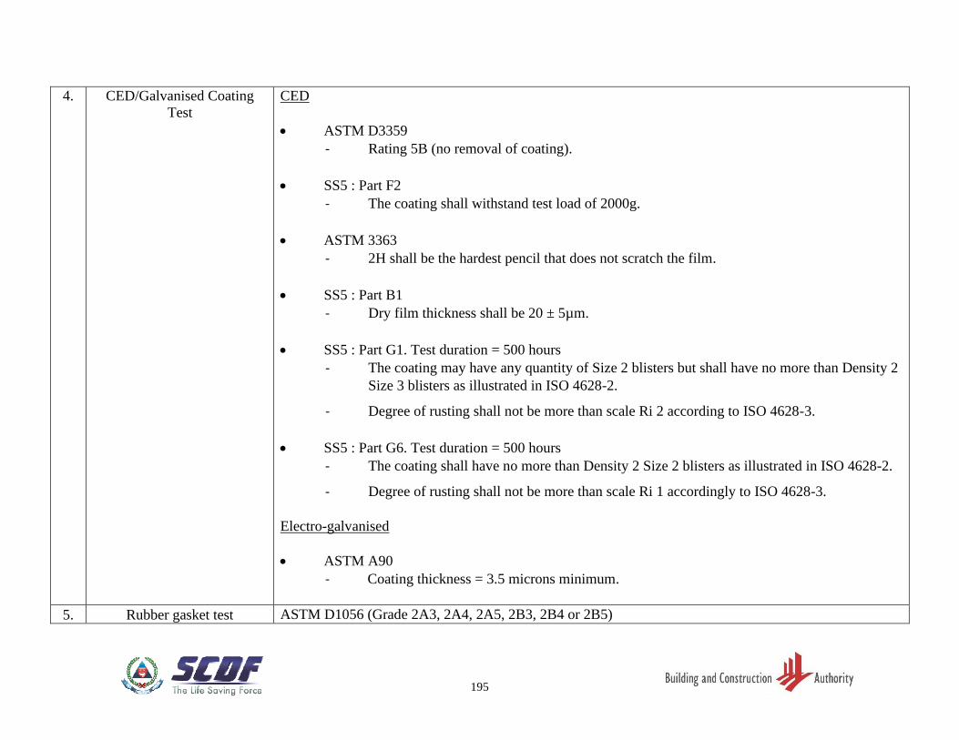
195
4. CED/Galvanised Coating
Test
CED
• ASTM D3359
- Rating 5B (no removal of coating).
• SS5 : Part F2
- The coating shall withstand test load of 2000g.
• ASTM 3363
- 2H shall be the hardest pencil that does not scratch the film.
• SS5 : Part B1
- Dry film thickness shall be 20 ± 5µm.
• SS5 : Part G1. Test duration = 500 hours
- The coating may have any quantity of Size 2 blisters but shall have no more than Density 2
Size 3 blisters as illustrated in ISO 4628-2.
- Degree of rusting shall not be more than scale Ri 2 according to ISO 4628-3.
• SS5 : Part G6. Test duration = 500 hours
- The coating shall have no more than Density 2 Size 2 blisters as illustrated in ISO 4628-2.
- Degree of rusting shall not be more than scale Ri 1 accordingly to ISO 4628-3.
Electro-galvanised
• ASTM A90
- Coating thickness = 3.5 microns minimum.
5. Rubber gasket test ASTM D1056 (Grade 2A3, 2A4, 2A5, 2B3, 2B4 or 2B5)
HQ Singapore Civil Defence Force
91 Ubi Ave 4, Singapore 408827
52 Jurong Gateway Road
#11-01, Singapore 608550