technical diary technical diary - wordpress.com
TRANSCRIPT

TECHNICAL DIARYTECHNICAL DIARYTECHNICAL DIARYTECHNICAL DIARY
BOILER AND AUXILIARIES
Prepared By Reviewed By Approved By S K VISHWAKARMA SUSHIL KUMAR M K SINGH
Asst Manager Manager AGM
STAGE-3 TECHNICAL DIARY (BOILER)
1
CONTENTS
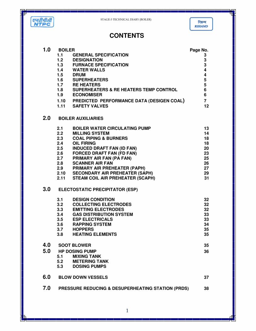
1.0 BOILER Page No. 1.1 GENERAL SPECIFICATION 3 1.2 DESIGNATION 3 1.3 FURNACE SPECIFICATION 3 1.4 WATER WALLS 4 1.5 DRUM 4 1.6 SUPERHEATERS 5 1.7 RE HEATERS 5 1.8 SUPERHEATERS & RE HEATERS TEMP CONTROL 6 1.9 ECONOMISER 6
1.10 PREDICTED PERFORMANCE DATA (DESIGEN COAL) 7 1.11 SAFETY VALVES 12
2.0 BOILER AUXILIARIES
2.1 BOILER WATER CIRCULATING PUMP 13 2.2 MILLING SYSTEM 14 2.3 COAL PIPING & BURNERS 18 2.4 OIL FIRING 18 2.5 INDUCED DRAFT FAN (ID FAN) 20 2.6 FORCED DRAFT FAN (FD FAN) 23 2.7 PRIMARY AIR FAN (PA FAN) 25 2.8 SCANNER AIR FAN 26 2.9 PRIMARY AIR PREHEATER (PAPH) 27 2.10 SECONDARY AIR PREHEATER (SAPH) 29 2.11 STEAM COIL AIR PREHEATER (SCAPH) 31
3.0 ELECTOSTATIC PRECIPITATOR (ESP)
3.1 DESIGN CONDITION 32 3.2 COLLECTING ELECTRODES 32 3.3 EMITTING ELECTRODES 32 3.4 GAS DISTRIBUTION SYSTEM 33 3.5 ESP ELECTRICALS 33 3.6 RAPPING SYSTEM 34 3.7 HOPPERS 35 3.8 HEATING ELEMENTS 35
4.0 SOOT BLOWER 35
5.0 HP DOSING PUMP 36 5.1 MIXING TANK 5.2 METERING TANK 5.3 DOSING PUMPS
6.0 BLOW DOWN VESSELS 37
7.0 PRESSURE REDUCING & DESUPERHEATING STATION (PRDS) 38
STAGE-3 TECHNICAL DIARY (BOILER)
2
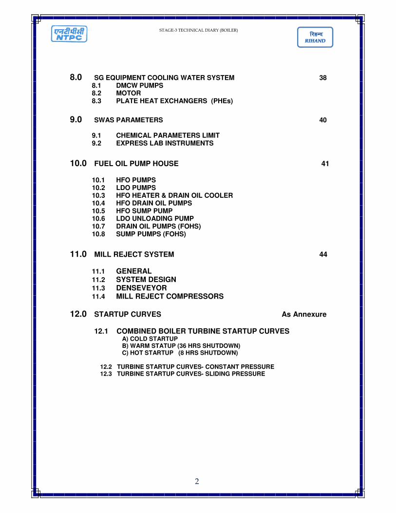
8.0 SG EQUIPMENT COOLING WATER SYSTEM 38 8.1 DMCW PUMPS 8.2 MOTOR 8.3 PLATE HEAT EXCHANGERS (PHEs)
9.0 SWAS PARAMETERS 40
9.1 CHEMICAL PARAMETERS LIMIT 9.2 EXPRESS LAB INSTRUMENTS
10.0 FUEL OIL PUMP HOUSE 41
10.1 HFO PUMPS 10.2 LDO PUMPS 10.3 HFO HEATER & DRAIN OIL COOLER 10.4 HFO DRAIN OIL PUMPS 10.5 HFO SUMP PUMP 10.6 LDO UNLOADING PUMP 10.7 DRAIN OIL PUMPS (FOHS) 10.8 SUMP PUMPS (FOHS)
11.0 MILL REJECT SYSTEM 44
11.1 GENERAL 11.2 SYSTEM DESIGN 11.3 DENSEVEYOR 11.4 MILL REJECT COMPRESSORS
12.0 STARTUP CURVES As Annexure 12.1 COMBINED BOILER TURBINE STARTUP CURVES
A) COLD STARTUP B) WARM STATUP (36 HRS SHUTDOWN) C) HOT STARTUP (8 HRS SHUTDOWN)
12.2 TURBINE STARTUP CURVES- CONSTANT PRESSURE 12.3 TURBINE STARTUP CURVES- SLIDING PRESSURE

STAGE-3 TECHNICAL DIARY (BOILER)
3
BOILER & ITS AUXILLIARIES
1.0 BOILER 1.1 GENERAL SPECIFICATION
Manufacturer M/S BHEL Type Controlled Circulation with Refilled tubing ,
(CC+) ,Dry bottom ,Radiant Reheat ,Single drum ,Top supported ,Balanced Draft Furnace
Type of firing Tilting Tangential
1.2 DESIGNATION
1.3 FURNANCE SPECIFICATION
Type Balance Draft Furnace With Fusion Welded Water Walls
Wall Water steam cooled
Tube arrangement Membrane
Residence time for fuel particles in the furnace
1.84 Sec.
Effective volume used to calculate the residence time
16424 M3
Depth 16115 mm Width 19177 mm Furnace volume 17599 M3 Drum elevation (C.L) 74.977 M Fuel heat input 1233.6X10b Kcal/hr @ BMCR DC
19177 301-51 CC+
16115 235-51
STAGE-3 TECHNICAL DIARY (BOILER)
4
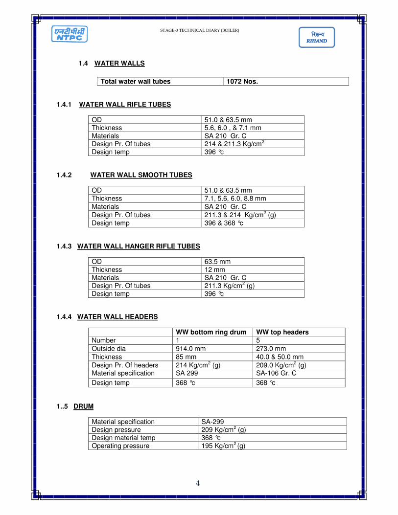
1.4 WATER WALLS
Total water wall tubes 1072 Nos.
1.4.1 WATER WALL RIFLE TUBES
OD 51.0 & 63.5 mm Thickness 5.6, 6.0 , & 7.1 mm
Materials SA 210 Gr. C Design Pr. Of tubes 214 & 211.3 Kg/cm2 Design temp 396 °c
1.4.2 WATER WALL SMOOTH TUBES
OD 51.0 & 63.5 mm
Thickness 7.1, 5.6, 6.0, 8.8 mm
Materials SA 210 Gr. C
Design Pr. Of tubes 211.3 & 214 Kg/cm2 (g)
Design temp 396 & 368 °c
1.4.3 WATER WALL HANGER RIFLE TUBES
OD 63.5 mm Thickness 12 mm
Materials SA 210 Gr. C Design Pr. Of tubes 211.3 Kg/cm2 (g) Design temp 396 °c
1.4.4 WATER WALL HEADERS
WW bottom ring drum WW top headers
Number 1 5
Outside dia 914.0 mm 273.0 mm
Thickness 85 mm 40.0 & 50.0 mm
Design Pr. Of headers 214 Kg/cm2 (g) 209.0 Kg/cm2 (g) Material specification SA 299 SA-106 Gr. C
Design temp 368 °c 368 °c
1..5 DRUM
Material specification SA-299 Design pressure 209 Kg/cm2 (g) Design material temp 368 °c Operating pressure 195 Kg/cm2 (g)
STAGE-3 TECHNICAL DIARY (BOILER)
5
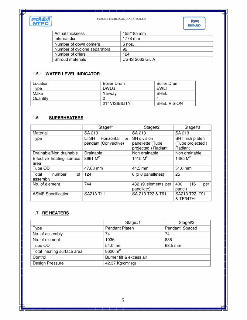
Actual thickness 155/185 mm Internal dia 1778 mm
Number of down comers 6 nos. Number of cyclone separators 92 Number of driers 124
Shroud materials CS-IS 2062 Gr. A
1.5.1 WATER LEVEL INDICATOR
Location Boiler Drum Boiler Drum Type DWLG EWLI
Make Yarway BHEL Quantity 2 4 21” VISIBILITY BHEL VISION
1.6 SUPERHEATERS
Stage#1 Stage#2 Stage#3
Material SA 213 SA 213 SA 213
Type LTSH Horizontal & pendant (Convective)
SH division panellette (Tube projected ) Radiant
SH finish platen (Tube projected ) Radiant
Drainable/Non drainable Drainable Non drainable Non drainable
Effective heating surface area
8661 M2 1415 M2 1485 M2
Tube OD 47.63 mm 44.5 mm 51.0 mm
Total number of assembly
124 6 (x 8 panelletes) 25
No. of element 744 432 (9 elements per panellete)
400 (16 per panel)
ASME Specification SA213 T11 SA 213 T22 & T91 SA213 T22, T91 & TP347H
1.7 RE HEATERS
Stage#1 Stage#2
Type Pendant Platen Pendant Spaced
No. of assembly 74 74
No. of element 1036 888
Tube OD 54.0 mm 63.5 mm
Total heating surface area 8620 m2
Control Burner tilt & excess air
Design Pressure 42.37 Kg/cm2 (g)
STAGE-3 TECHNICAL DIARY (BOILER)
6
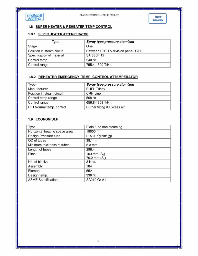
1.8 SUPER HEATER & REHEATER TEMP CONTROL
1.8.1 SUPER HEATER ATTEMPERATOR
Type Spray type pressure atomized
Stage One
Position in steam circuit Between LTSH & division panel S/H
Specification of material SA 335P 12
Control temp 540 °c
Control range 755.4-1590 T/Hr.
1.8.2 REHEATER EMERGENCY TEMP. CONTROL ATTEMPERATOR
Type Spray type pressure atomized
Manufacturer BHEL Trichy
Position in steam circuit CRH Line
Control temp range 568 °c
Control range 656.8-1358 T/Hr.
R/H Normal temp. control Burner tilting & Excess air
1.9 ECONOMISER
Type Plain tube non steaming
Horizontal heating space area 19000 m2
Design Pressure tube 215.0 Kg/cm2 (g)
OD of tubes 38.1 mm
Minimum thickness of tubes 5.3 mm
Length of tubes 296.4 m
Pitch 103 mm (ST) 76.2 mm (SL)
No. of blocks 3 Nos.
Assembly 184
Element 552
Design temp. 336 °c
ASME Specification SA210 Gr A1
STAGE-3 TECHNICAL DIARY (BOILER)
7
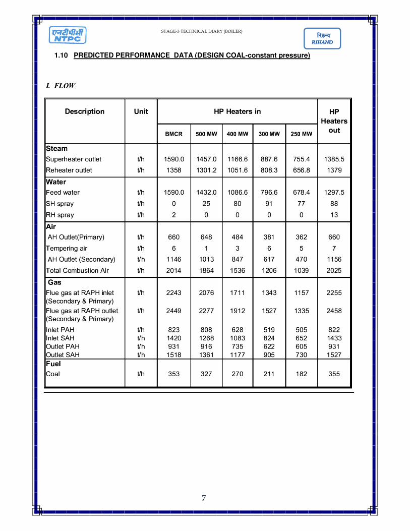
1.10 PREDICTED PERFORMANCE DATA (DESIGN COAL-constant pressure)
STAGE-3 TECHNICAL DIARY (BOILER)
8
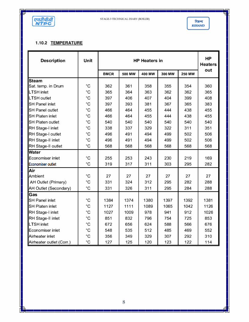
1.10.2 TEMPERATURE
STAGE-3 TECHNICAL DIARY (BOILER)
9
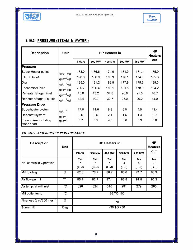
1.10.3 PRESSURE (STEAM & WATER )
STAGE-3 TECHNICAL DIARY (BOILER)
10
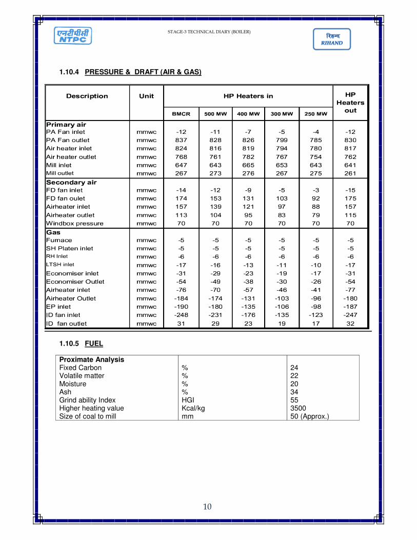
1.10.4 PRESSURE & DRAFT (AIR & GAS)
1.10.5 FUEL
Proximate Analysis Fixed Carbon Volatile matter Moisture Ash Grind ability Index Higher heating value Size of coal to mill
% % % % HGI Kcal/kg mm
24 22 20 34 55 3500 50 (Approx.)
STAGE-3 TECHNICAL DIARY (BOILER)
11
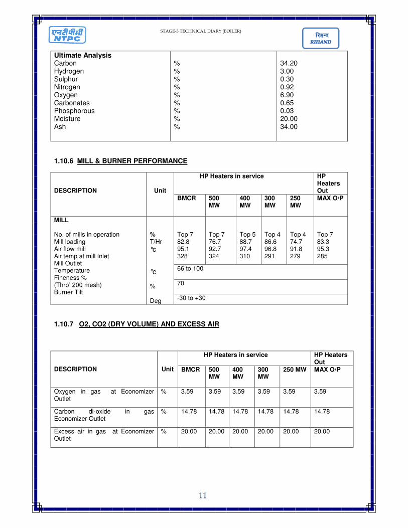
Ultimate Analysis Carbon Hydrogen Sulphur Nitrogen Oxygen Carbonates Phosphorous Moisture Ash
% % % % % % % % %
34.20 3.00 0.30 0.92 6.90 0.65 0.03 20.00 34.00
1.10.6 MILL & BURNER PERFORMANCE
DESCRIPTION
Unit
HP Heaters in service HP Heaters Out
BMCR 500 MW
400 MW
300 MW
250 MW
MAX O/P
MILL No. of mills in operation Mill loading Air flow mill Air temp at mill Inlet Mill Outlet Temperature Fineness % (Thro’ 200 mesh) Burner Tilt
% T/Hr
°c
°c % Deg
Top 7 82.8 95.1 328
Top 7 76.7 92.7 324
Top 5 88.7 97.4 310
Top 4 86.6 96.8 291
Top 4 74.7 91.8 279
Top 7 83.3 95.3 285
66 to 100
70
-30 to +30
1.10.7 O2, CO2 (DRY VOLUME) AND EXCESS AIR
DESCRIPTION
Unit
HP Heaters in service HP Heaters Out
BMCR 500 MW
400 MW
300 MW
250 MW MAX O/P
Oxygen in gas at Economizer Outlet
%
3.59 3.59 3.59 3.59 3.59 3.59
Carbon di-oxide in gas Economizer Outlet
% 14.78 14.78 14.78 14.78 14.78 14.78
Excess air in gas at Economizer Outlet
% 20.00 20.00 20.00 20.00 20.00 20.00

STAGE-3 TECHNICAL DIARY (BOILER)
12
1.10.8 HEAT BALANCE
DESCRIPTION
Unit
HP Heaters in service HP Heaters Out
BMCR 500 MW
400 MW
300 MW
250 MW MAX O/P
LOSSES Dry gas H2O on fuel, surf & inherent H2O from comb. Of H2
H2O in air Unburnt carbon Radiation Unaccounted Manufactures margin Total losses
% % % % % % % %
%
4.229 3.502 4.695 0.109 1.500 0.216 0.784 0.150 15.185
4.165 3.496 4.687 0.107 1.500 0.234 0.784 0.150 15.123
4.157 3.490 4.679 0.107 1.500 0.283 0.791 0.150 15.157
4.237 3.489 4.678 .109 1.500 0.361 0.807 0.150 15.331
4.256 3.485 4.672 0.109 1.500 0.419 0.817 0.150 15.408
3.668 3.469 4.651 0.094 1.500 0.215 0.760 0.150 14.507
Efficiency % 84.81 84.87 84.84 84.66 84.59 85.49
1.11 SAFETY VALVES
LOCATION
SL. NO.
VALVE TAG
NO.
TYPE OF SAFETY
VALVE
VALVE SET PR.
KG/CM2 (G)
% O
F
BL
OW
D
OW
N
RELIEVING CAPACITY KG/HR.
OPEN CLOSE
BOILER DRUM
1 SV1 CONSOL 1750 WB 209 200.6 4.0 212800
2 SV2 CONSOL 1750 WB 211.1 200.5 5.0 214928
3 SV3 & SV4 CONSOL 1750 WB 213.2 202.5 5.0 217056
4 SV5 & SV6 CONSOL 1740 WB 215.3 204.5 5.0 261228
SH SV 5 SV7 & SV8 CONSOL 1740 WD 188.5 181.3 3.8 187670
SH ERV
6 SV9 & SV10 CONSOL 1538 VX-10 W 185.5 180.3 2.8 116388
7 SV11, SV12 & SV13
CONSOL 1538 VX-10 W 186.6 180.6 3.2 86945
CRH
8 SV14 & SV15 CONSOL 1786 WB 52.40 49.8 5.0 207461
9 SV16 & SV17 CONSOL 1786 WB 54.0 51.3 5.0 214147
HRH SV 10 SV18 & SV19 CONSOL 1786 WE 48.4 46.0 5.0 157460
11 SV20 & SV21 CONSOL 1786 WE 49.9 47.4 5.0 162457
HRH ERV 12 SV22 & SV23 CONSOL 1525 VX 47.4 46.5 2.0 117191
13 SV24 & SV25 CONSOL 1525 VX 47.9 46.9 2.0 118402
SOOT BLOWER
14 SV30 CONSOL 1811 LC 6X 40.0 38.4 4.0 29970
STAGE-3 TECHNICAL DIARY (BOILER)
13
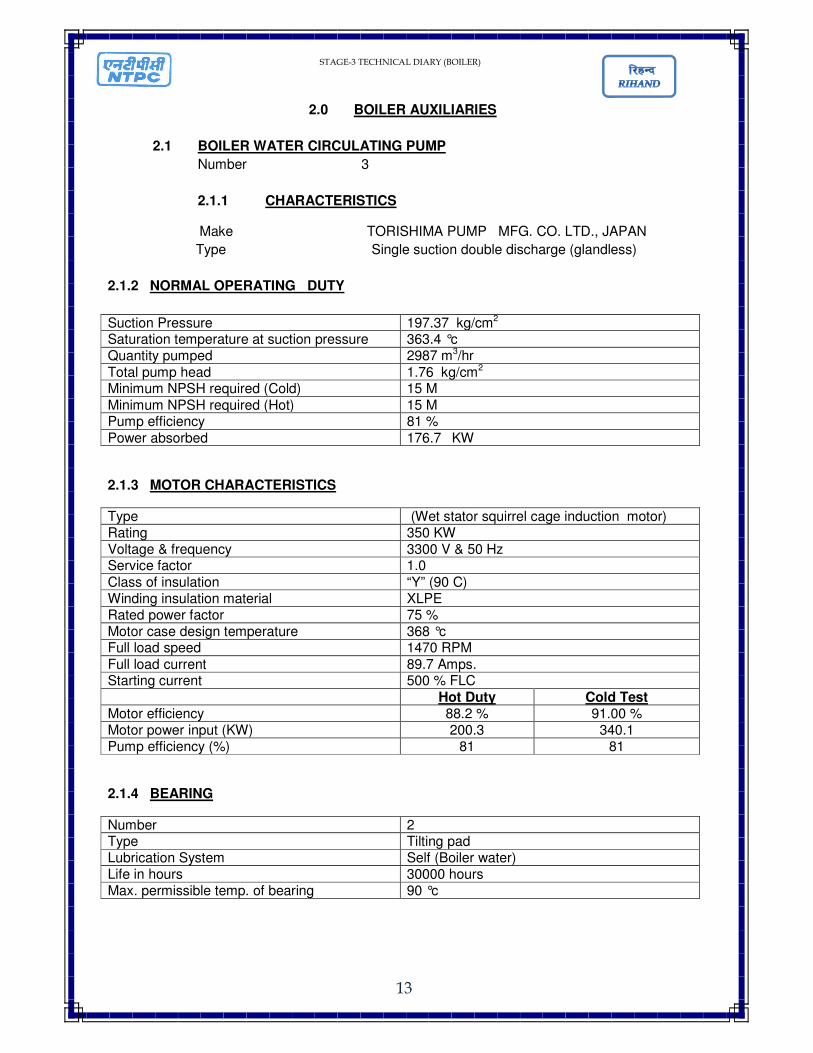
2.0 BOILER AUXILIARIES
2.1 BOILER WATER CIRCULATING PUMP
Number 3
2.1.1 CHARACTERISTICS
Make TORISHIMA PUMP MFG. CO. LTD., JAPAN
Type Single suction double discharge (glandless)
2.1.2 NORMAL OPERATING DUTY
Suction Pressure 197.37 kg/cm2 Saturation temperature at suction pressure 363.4 °c Quantity pumped 2987 m3/hr
Total pump head 1.76 kg/cm2 Minimum NPSH required (Cold) 15 M
Minimum NPSH required (Hot) 15 M Pump efficiency 81 %
Power absorbed 176.7 KW
2.1.3 MOTOR CHARACTERISTICS
Type (Wet stator squirrel cage induction motor) Rating 350 KW Voltage & frequency 3300 V & 50 Hz Service factor 1.0
Class of insulation “Y” (90 C) Winding insulation material XLPE Rated power factor 75 % Motor case design temperature 368 °c Full load speed 1470 RPM
Full load current 89.7 Amps. Starting current 500 % FLC
Hot Duty Cold Test Motor efficiency 88.2 % 91.00 % Motor power input (KW) 200.3 340.1 Pump efficiency (%) 81 81
2.1.4 BEARING
Number 2 Type Tilting pad Lubrication System Self (Boiler water) Life in hours 30000 hours Max. permissible temp. of bearing 90 °c
STAGE-3 TECHNICAL DIARY (BOILER)
14
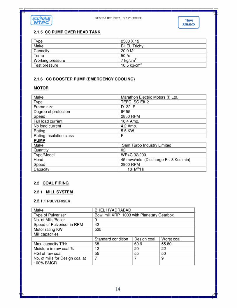
2.1.5 CC PUMP OVER HEAD TANK
Type 2500 X 12 Make BHEL Trichy Capacity 20.0 M3 Temp 50 °c Working pressure 7 kg/cm2 Test pressure 10.5 kg/cm2
2.1.6 CC BOOSTER PUMP (EMERGENCY COOLING)
MOTOR
Make Marathon Electric Motors (I) Ltd. Type TEFC SC Eff-2
Frame size D132 S Degree of protection IP 55 Speed 2850 RPM
Full load current 10.4 Amp. No load current 4.2 Amp.
Rating 5.5 KW Rating Insulation class F PUMP Make Sam Turbo Industry Limited Quantity 02
Type/Model WP+C 32/200. Head 45 mwc/mlc (Discharge Pr.-8 Ksc min)
Speed 2900 RPM Capacity 10 M3/Hr
2.2 COAL FIRING
2.2.1 MILL SYSTEM
2.2.1.1 PULVERISER
Make BHEL HYADRABAD
Type of Pulveriser Bowl mill XRP 1003 with Planetary Gearbox No. of Mills/Boiler 9 Speed of Pulveriser in RPM 42
Motor rating KW 525 Mill capacities
Standard condition Design coal Worst coal Max. capacity T/Hr 68 60.9 55.80 Moisture in raw coal % 12 20 22
HGI of raw coal 55 55 50 No. of mills for Design coal at 100% BMCR
7 7 9

STAGE-3 TECHNICAL DIARY (BOILER)
15
2.2.1.2 MILL MOTOR
Manufacturer BHEL, BHOPAL Motor type SCIM Standard continuous rating at 40 °c ambient temp. (As per IS)
525 KW
Rated voltage 3300 V Permissible variation of Voltage +/- 6.0 Frequency +3 -5 Combined Voltage & Frequency 10% Abs Minimum Permissible starting voltage (% ) 85 Rated speed at rated voltage & freq (RPM) 984 Starting time with minimum permissible Voltage
Without driven equipment 0.5 Sec With driven equipment coupled 5.7 Sec At rated Voltage & Frequency Full load current 129 Amp No load current (A) 55 Amp
2.2.1.3 MILL MOTOR BEARING
Drive-End Non- Drive-End
(A) Type NU 228M+62283 NU 224M
(B) Recommended Lubricant Grease IOC servo gem -3/Eqv
2.2.1.4 MILL EXTERNAL LUBRICTION SYSTEM
Manufacturer: TA Hydraulics Pvt. Ltd. Hyderabad
2.2.1.4.1 PUMPS
Make Type Three screw pump Quantity 2X100 % Capacity 150 LPM Speed 1450 RPM Coupling Love joy Operating Pressure 3 to 5 Bar Relief valve setting 8.5 Bar Filter 25 micron SS mesh, Test Press-22 ksc Operating fluid ISO VG 320
STAGE-3 TECHNICAL DIARY (BOILER)
16
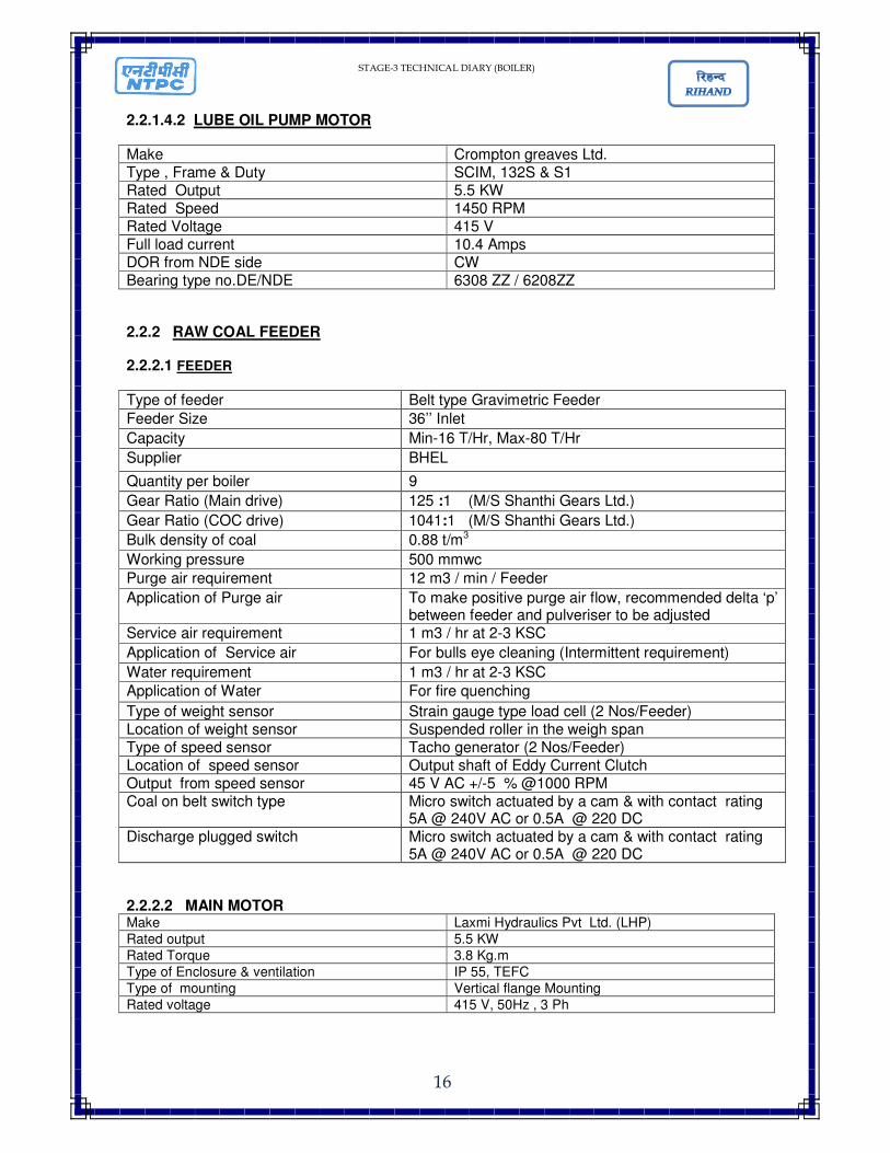
2.2.1.4.2 LUBE OIL PUMP MOTOR
Make Crompton greaves Ltd. Type , Frame & Duty SCIM, 132S & S1 Rated Output 5.5 KW Rated Speed 1450 RPM Rated Voltage 415 V Full load current 10.4 Amps DOR from NDE side CW Bearing type no.DE/NDE 6308 ZZ / 6208ZZ
2.2.2 RAW COAL FEEDER
2.2.2.1 FEEDER
Type of feeder Belt type Gravimetric Feeder
Feeder Size 36’’ Inlet
Capacity Min-16 T/Hr, Max-80 T/Hr
Supplier BHEL
Quantity per boiler 9
Gear Ratio (Main drive) 125 :1 (M/S Shanthi Gears Ltd.)
Gear Ratio (COC drive) 1041:1 (M/S Shanthi Gears Ltd.)
Bulk density of coal 0.88 t/m3
Working pressure 500 mmwc
Purge air requirement 12 m3 / min / Feeder
Application of Purge air To make positive purge air flow, recommended delta ‘p’ between feeder and pulveriser to be adjusted
Service air requirement 1 m3 / hr at 2-3 KSC
Application of Service air For bulls eye cleaning (Intermittent requirement)
Water requirement 1 m3 / hr at 2-3 KSC
Application of Water For fire quenching
Type of weight sensor Strain gauge type load cell (2 Nos/Feeder) Location of weight sensor Suspended roller in the weigh span Type of speed sensor Tacho generator (2 Nos/Feeder) Location of speed sensor Output shaft of Eddy Current Clutch Output from speed sensor 45 V AC +/-5 % @1000 RPM Coal on belt switch type Micro switch actuated by a cam & with contact rating
5A @ 240V AC or 0.5A @ 220 DC Discharge plugged switch Micro switch actuated by a cam & with contact rating
5A @ 240V AC or 0.5A @ 220 DC
2.2.2.2 MAIN MOTOR Make Laxmi Hydraulics Pvt Ltd. (LHP)
Rated output 5.5 KW
Rated Torque 3.8 Kg.m
Type of Enclosure & ventilation IP 55, TEFC
Type of mounting Vertical flange Mounting
Rated voltage 415 V, 50Hz , 3 Ph
STAGE-3 TECHNICAL DIARY (BOILER)
17
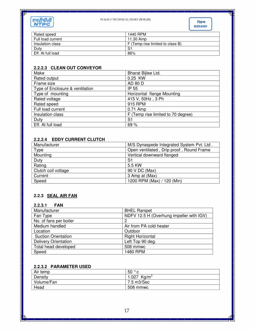
Rated speed 1440 RPM
Full load current 11.30 Amp
Insulation class F (Temp rise limited to class B)
Duty S1
Eff. At full load 86%
2.2.2.3 CLEAN OUT CONVEYOR Make Bharat Bijlee Ltd. Rated output 0.25 KW Frame size AD 80 D Type of Enclosure & ventilation IP 55 Type of mounting Horizontal flange Mounting Rated voltage 415 V, 50Hz , 3 Ph Rated speed 915 RPM Full load current 0.71 Amp Insulation class F (Temp rise limited to 70 degree) Duty S1 Eff. At full load 69 %
2.2.2.4 EDDY CURRENT CLUTCH
Manufacturer M/S Dynaspede Integrated System Pvt. Ltd . Type Open ventilated , Drip proof , Round Frame Mounting Vertical downward flanged Duty S1 Rating 5.5 KW Clutch coil voltage 90 V DC (Max) Current 3 Amp at (Max) Speed 1200 RPM (Max) / 120 (Min)
2.2.3 SEAL AIR FAN
2.2.3.1 FAN
Manufacturer BHEL Ranipet Fan Type NDFV 12.5 H (Overhung impeller with IGV)
No. of fans per boiler 2 Medium handled Air from PA cold heater Location Outdoor
Suction Orientation Right Horizontal Delivery Orientation Left Top 90 deg.
Total head developed 508 mmwc Speed 1480 RPM
2.2.3.2 PARAMETER USED Air temp 50 ° c Density 1.027 Kg/m3 Volume/Fan 7.5 m3/Sec
Head 508 mmwc

STAGE-3 TECHNICAL DIARY (BOILER)
18
2.2.3.3 SEAL AIR FAN DRIVE MOTOR
Make Crompton Greaves Rating 75 KW Rated Voltage 415 (+/-) 10% Frequency 50 Hz +3%/- 5 % Speed 1480 rpm Full load current 134 Amps DOR CW as viewed from DE end
2.2.3.4 BEARING LUBRICATION
Quantity 20 ltrs/fan Grade Servo prime 68,Bharat turbol 68,turbinol
68,teresso 68 Recommended interval of Lubrication Once in Six months
2.2.3.5 BEARING TYPE
Fixed Bearing NU314/C3
Free Bearing 6314
2.3 COAL PIPING & BURNERS
2.3.1 COAL PIPING Material of straight pipe Carbon steel Fuel pipe diameter 660.4 mm Fuel pipe thickness 14.2 mm
2.3.2 COAL BURNERS Type Tilting Tangential Make BHEL No. of coal burners feed by each mill 4 (Total No. of coal burners 36) No. of burners elevation 9
Temp of coal air mixture in PF Pipes 75 ° c
2.4 OIL FIRING SYSTEM
2.4.1 HEAVY FURNACE OIL BURNERS Burner Tilting Tangential; Corner fired Oil gun Parallel piping design, Steam atomized
External mixed; Constant pressure atomizer Air nozzle Rectangular Diffuser 190 mm; 10 off 45 ° c vanes with leading
edge with scanner & ignitor cuttings Oil gun assembly dimension KF=2689+/-3 mm Atomizer Designation Spray plate 90 J24
STAGE-3 TECHNICAL DIARY (BOILER)
19
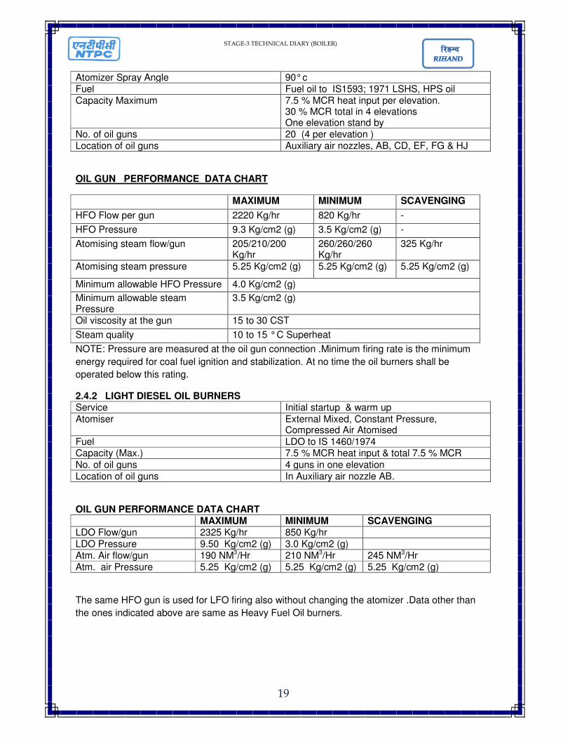
Atomizer Spray Angle 90° c Fuel Fuel oil to IS1593; 1971 LSHS, HPS oil Capacity Maximum 7.5 % MCR heat input per elevation.
30 % MCR total in 4 elevations One elevation stand by
No. of oil guns 20 (4 per elevation ) Location of oil guns Auxiliary air nozzles, AB, CD, EF, FG & HJ
OIL GUN PERFORMANCE DATA CHART
MAXIMUM MINIMUM SCAVENGING
HFO Flow per gun 2220 Kg/hr 820 Kg/hr -
HFO Pressure 9.3 Kg/cm2 (g) 3.5 Kg/cm2 (g) -
Atomising steam flow/gun 205/210/200 Kg/hr
260/260/260 Kg/hr
325 Kg/hr
Atomising steam pressure 5.25 Kg/cm2 (g) 5.25 Kg/cm2 (g) 5.25 Kg/cm2 (g)
Minimum allowable HFO Pressure 4.0 Kg/cm2 (g)
Minimum allowable steam Pressure
3.5 Kg/cm2 (g)
Oil viscosity at the gun 15 to 30 CST
Steam quality 10 to 15 ° C Superheat
NOTE: Pressure are measured at the oil gun connection .Minimum firing rate is the minimum
energy required for coal fuel ignition and stabilization. At no time the oil burners shall be
operated below this rating.
2.4.2 LIGHT DIESEL OIL BURNERS Service Initial startup & warm up
Atomiser External Mixed, Constant Pressure, Compressed Air Atomised
Fuel LDO to IS 1460/1974 Capacity (Max.) 7.5 % MCR heat input & total 7.5 % MCR
No. of oil guns 4 guns in one elevation Location of oil guns In Auxiliary air nozzle AB.
OIL GUN PERFORMANCE DATA CHART MAXIMUM MINIMUM SCAVENGING LDO Flow/gun 2325 Kg/hr 850 Kg/hr LDO Pressure 9.50 Kg/cm2 (g) 3.0 Kg/cm2 (g) Atm. Air flow/gun 190 NM3/Hr 210 NM3/Hr 245 NM3/Hr Atm. air Pressure 5.25 Kg/cm2 (g) 5.25 Kg/cm2 (g) 5.25 Kg/cm2 (g)
The same HFO gun is used for LFO firing also without changing the atomizer .Data other than
the ones indicated above are same as Heavy Fuel Oil burners.
STAGE-3 TECHNICAL DIARY (BOILER)
20
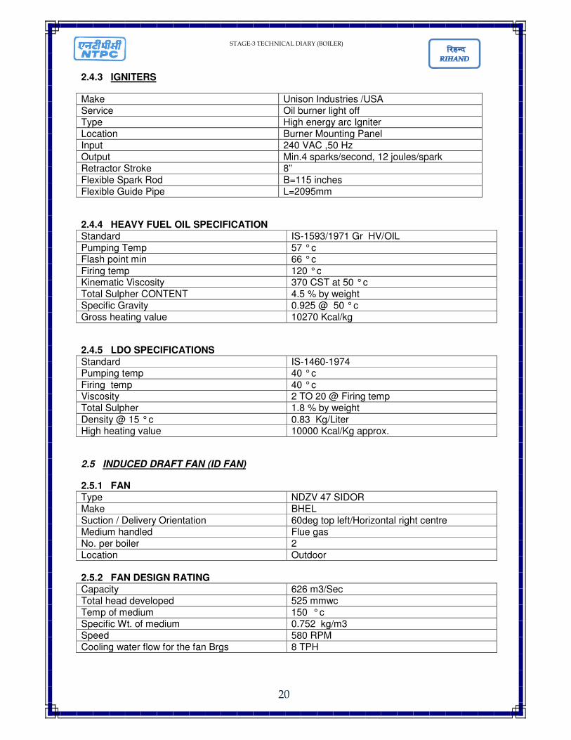
2.4.3 IGNITERS
Make Unison Industries /USA Service Oil burner light off Type High energy arc Igniter Location Burner Mounting Panel Input 240 VAC ,50 Hz Output Min.4 sparks/second, 12 joules/spark Retractor Stroke 8” Flexible Spark Rod B=115 inches Flexible Guide Pipe L=2095mm
2.4.4 HEAVY FUEL OIL SPECIFICATION Standard IS-1593/1971 Gr HV/OIL
Pumping Temp 57 ° c Flash point min 66 ° c
Firing temp 120 ° c Kinematic Viscosity 370 CST at 50 ° c Total Sulpher CONTENT 4.5 % by weight Specific Gravity 0.925 @ 50 ° c Gross heating value 10270 Kcal/kg
2.4.5 LDO SPECIFICATIONS
Standard IS-1460-1974 Pumping temp 40 ° c
Firing temp 40 ° c Viscosity 2 TO 20 @ Firing temp Total Sulpher 1.8 % by weight
Density @ 15 ° c 0.83 Kg/Liter High heating value 10000 Kcal/Kg approx.
2.5 INDUCED DRAFT FAN (ID FAN)
2.5.1 FAN Type NDZV 47 SIDOR Make BHEL Suction / Delivery Orientation 60deg top left/Horizontal right centre Medium handled Flue gas No. per boiler 2 Location Outdoor 2.5.2 FAN DESIGN RATING Capacity 626 m3/Sec Total head developed 525 mmwc Temp of medium 150 ° c Specific Wt. of medium 0.752 kg/m3 Speed 580 RPM Cooling water flow for the fan Brgs 8 TPH
STAGE-3 TECHNICAL DIARY (BOILER)
21
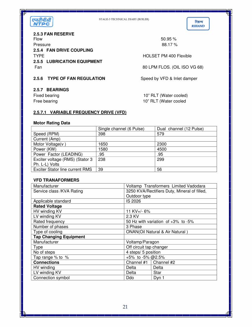
2.5.3 FAN RESERVE Flow 50.95 %
Pressure 88.17 %
2.5.4 FAN DRIVE COUPLING
TYPE HOLSET PM 400 Flexible
2.5.5 LUBRICATION EQUIPMENT
Fan 80 LPM FLOS. (OIL ISO VG 68)
2.5.6 TYPE OF FAN REGULATION Speed by VFD & Inlet damper
2.5.7 BEARINGS
Fixed bearing 10” RLT (Water cooled)
Free bearing 10” RLT (Water cooled
2.5.7.1 VARIABLE FREQUENCY DRIVE (VFD)
Motor Rating Data
Single channel (6 Pulse) Dual channel (12 Pulse) Speed (RPM) 398 579 Current (Amp) Motor Voltage(v ) 1650 2300 Power (KW) 1580 4500 Power Factor (LEADING) .95 .95 Exciter voltage (RMS) (Stator 3 Ph. L-L) Volts
238 299
Exciter Stator line current RMS 39 56
VFD TRANAFORMERS
Manufacturer Voltamp Transformers Limited Vadodara Service class /KVA Rating 3250 KVA/Rectifiers Duty, Mineral of filled,
Outdoor type Applicable standard IS 2026 Rated Voltage HV winding KV 11 KV+/- 6% LV winding KV 2.3 KV Rated frequency 50 Hz with variation of +3% to -5% Number of phases 3 Phase Type of cooling ONAN(Oil Natural & Air Natural ) Tap Changing Equipment
Manufacturer Voltamp/Paragon Type Off circuit tap changer No of steps 4 steps/ 5 position Tap range % to % +5% to -5% @2.5% Connections Channel #1 Channel #2 HV winding Delta Delta LV winding KV Delta Star
Connection symbol Ddo Dyn 1
STAGE-3 TECHNICAL DIARY (BOILER)
22
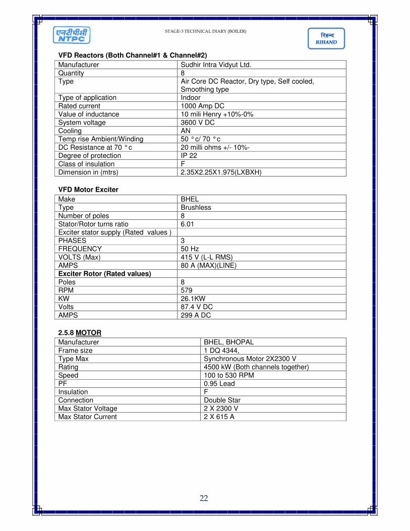
VFD Reactors (Both Channel#1 & Channel#2)
Manufacturer Sudhir Intra Vidyut Ltd.
Quantity 8 Type Air Core DC Reactor, Dry type, Self cooled,
Smoothing type Type of application Indoor
Rated current 1000 Amp DC Value of inductance 10 mili Henry +10%-0% System voltage 3600 V DC Cooling AN Temp rise Ambient/Winding 50 ° c/ 70 ° c
DC Resistance at 70 ° c 20 milli ohms +/- 10%- Degree of protection IP 22
Class of insulation F Dimension in (mtrs) 2.35X2.25X1.975(LXBXH)
VFD Motor Exciter
Make BHEL Type Brushless
Number of poles 8 Stator/Rotor turns ratio 6.01 Exciter stator supply (Rated values )
PHASES 3 FREQUENCY 50 Hz
VOLTS (Max) 415 V (L-L RMS) AMPS 80 A (MAX)(LINE) Exciter Rotor (Rated values)
Poles 8 RPM 579
KW 26.1KW Volts 87.4 V DC
AMPS 299 A DC
2.5.8 MOTOR
Manufacturer BHEL, BHOPAL
Frame size 1 DQ 4344, Type Max Synchronous Motor 2X2300 V Rating 4500 kW (Both channels together) Speed 100 to 530 RPM PF 0.95 Lead Insulation F Connection Double Star Max Stator Voltage 2 X 2300 V Max Stator Current 2 X 615 A
STAGE-3 TECHNICAL DIARY (BOILER)
23
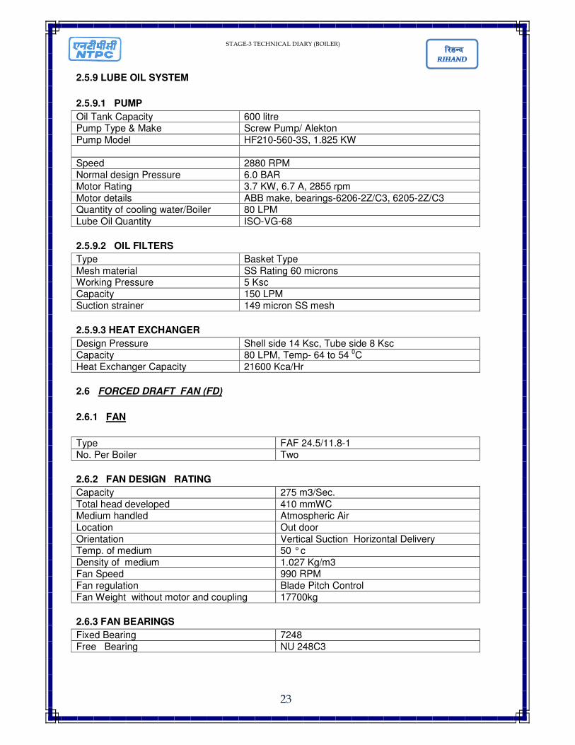
2.5.9 LUBE OIL SYSTEM
2.5.9.1 PUMP
Oil Tank Capacity 600 litre Pump Type & Make Screw Pump/ Alekton
Pump Model HF210-560-3S, 1.825 KW
Speed 2880 RPM Normal design Pressure 6.0 BAR Motor Rating 3.7 KW, 6.7 A, 2855 rpm
Motor details ABB make, bearings-6206-2Z/C3, 6205-2Z/C3 Quantity of cooling water/Boiler 80 LPM
Lube Oil Quantity ISO-VG-68
2.5.9.2 OIL FILTERS
Type Basket Type
Mesh material SS Rating 60 microns Working Pressure 5 Ksc Capacity 150 LPM Suction strainer 149 micron SS mesh
2.5.9.3 HEAT EXCHANGER
Design Pressure Shell side 14 Ksc, Tube side 8 Ksc Capacity 80 LPM, Temp- 64 to 54 0C Heat Exchanger Capacity 21600 Kca/Hr
2.6 FORCED DRAFT FAN (FD)
2.6.1 FAN
Type FAF 24.5/11.8-1 No. Per Boiler Two
2.6.2 FAN DESIGN RATING
Capacity 275 m3/Sec.
Total head developed 410 mmWC Medium handled Atmospheric Air Location Out door
Orientation Vertical Suction Horizontal Delivery Temp. of medium 50 ° c
Density of medium 1.027 Kg/m3 Fan Speed 990 RPM Fan regulation Blade Pitch Control Fan Weight without motor and coupling 17700kg
2.6.3 FAN BEARINGS
Fixed Bearing 7248 Free Bearing NU 248C3
STAGE-3 TECHNICAL DIARY (BOILER)
24
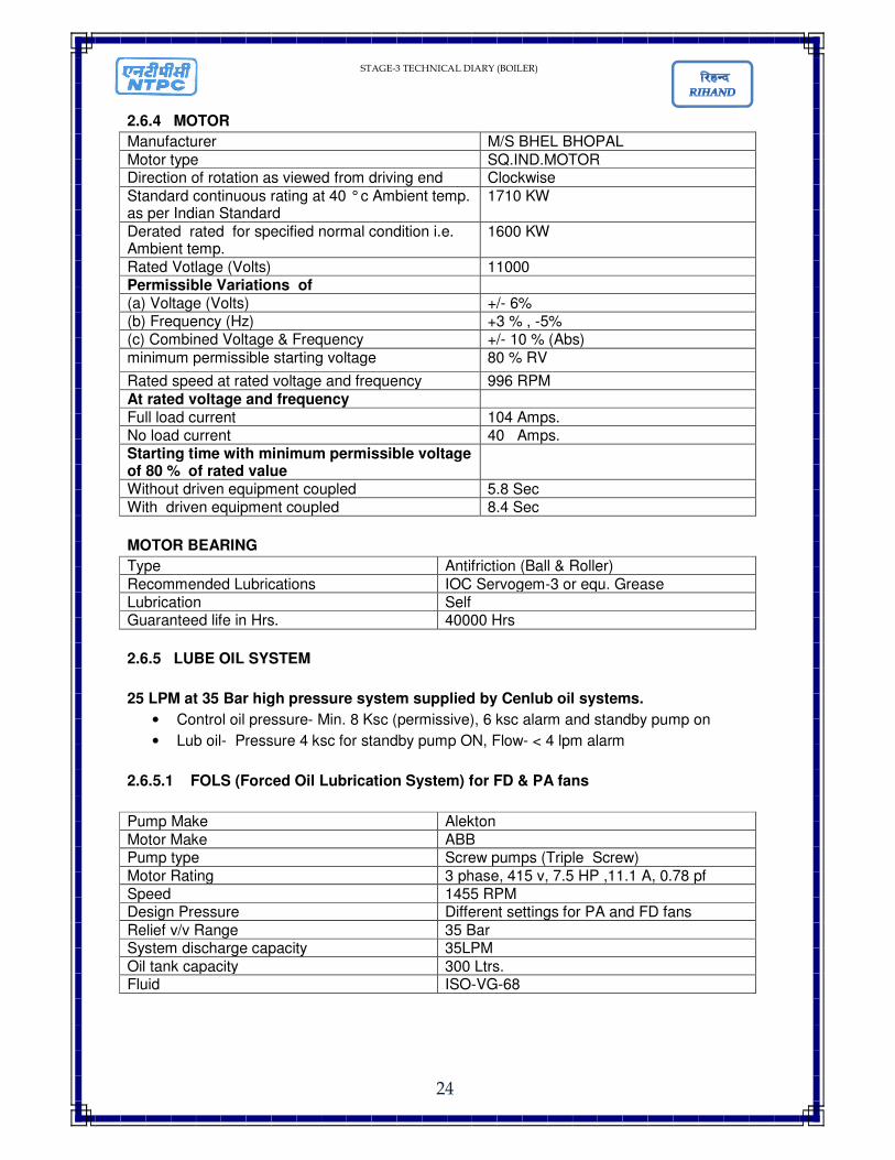
2.6.4 MOTOR
Manufacturer M/S BHEL BHOPAL
Motor type SQ.IND.MOTOR Direction of rotation as viewed from driving end Clockwise
Standard continuous rating at 40 ° c Ambient temp. as per Indian Standard
1710 KW
Derated rated for specified normal condition i.e. Ambient temp.
1600 KW
Rated Votlage (Volts) 11000 Permissible Variations of (a) Voltage (Volts) +/- 6% (b) Frequency (Hz) +3 % , -5% (c) Combined Voltage & Frequency +/- 10 % (Abs)
minimum permissible starting voltage 80 % RV
Rated speed at rated voltage and frequency 996 RPM
At rated voltage and frequency Full load current 104 Amps. No load current 40 Amps. Starting time with minimum permissible voltage of 80 % of rated value
Without driven equipment coupled 5.8 Sec With driven equipment coupled 8.4 Sec
MOTOR BEARING
Type Antifriction (Ball & Roller)
Recommended Lubrications IOC Servogem-3 or equ. Grease Lubrication Self Guaranteed life in Hrs. 40000 Hrs
2.6.5 LUBE OIL SYSTEM
25 LPM at 35 Bar high pressure system supplied by Cenlub oil systems.
• Control oil pressure- Min. 8 Ksc (permissive), 6 ksc alarm and standby pump on
• Lub oil- Pressure 4 ksc for standby pump ON, Flow- < 4 lpm alarm
2.6.5.1 FOLS (Forced Oil Lubrication System) for FD & PA fans
Pump Make Alekton
Motor Make ABB Pump type Screw pumps (Triple Screw)
Motor Rating 3 phase, 415 v, 7.5 HP ,11.1 A, 0.78 pf Speed 1455 RPM Design Pressure Different settings for PA and FD fans
Relief v/v Range 35 Bar System discharge capacity 35LPM
Oil tank capacity 300 Ltrs. Fluid ISO-VG-68
STAGE-3 TECHNICAL DIARY (BOILER)
25
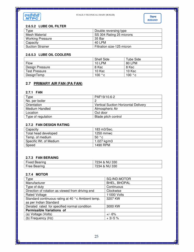
2.6.5.2 LUBE OIL FILTER
Type Double reversing type
Mesh Material SS 304 Rating 25 microns Working Pressure 35 Bar
Capacity 40 LPM Suction Strainer Filtration size-125 micron
2.6.5.3 LUBE OIL COOLERS
Shell Side Tube Side Flow 10 LPM 80 LPM
Design Pressure 8 Ksc 8 Ksc Test Pressure 10 Ksc 10 Ksc DesignTemp 100 ° c 100 ° c
2.7 PRIMARY AIR FAN (PA FAN)
2.7.1 FAN
Type PAF19/10.6-2 No. per boiler 2
Orientation Vertical Suction Horizontal Delivery Medium Handled Atmospheric Air Location Out door
Type of regulation Blade pitch control
2.7.2 FAN DESIGN RATING
Capacity 183 m3/Sec. Total head developed 1250 mmwc Temp. of medium 50 ° c Specific Wt. of Medium 1.027 kg/m3 Speed 1490 RPM
2.7.3 FAN BERAING
Fixed Bearing 7234 & NU 330
Free Bearing 7234 & NU 330
2.7.4 MOTOR
Type SQ.IND.MOTOR
Manufacturer BHEL, BHOPAL Type of duty Continuous
Direction of rotation as viewed from driving end Clockwise Rated Voltage 11000 Volts Standard continuous rating at 40 ° c Ambient temp. as per Indian Standard
3207 KW
Derated rated for specified normal condition 3000 KW Permissible Variations of (a) Voltage (Volts) +/- 6%
(b) Frequency (Hz) + 3/-5 %
STAGE-3 TECHNICAL DIARY (BOILER)
26
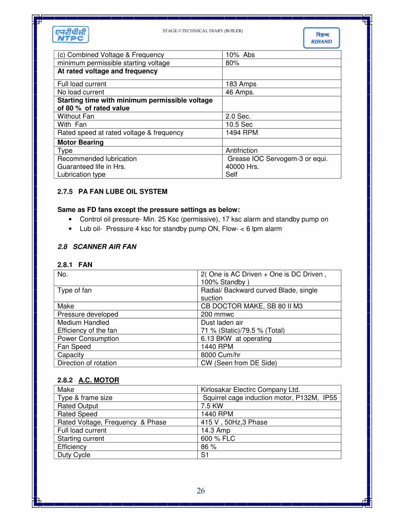
(c) Combined Voltage & Frequency 10% Abs minimum permissible starting voltage 80% At rated voltage and frequency
Full load current 183 Amps No load current 46 Amps. Starting time with minimum permissible voltage of 80 % of rated value
Without Fan 2.0 Sec. With Fan 10.5 Sec Rated speed at rated voltage & frequency 1494 RPM
Motor Bearing Type Antifriction Recommended lubrication Guaranteed life in Hrs. Lubrication type
Grease IOC Servogem-3 or equi. 40000 Hrs. Self
2.7.5 PA FAN LUBE OIL SYSTEM
Same as FD fans except the pressure settings as below:
• Control oil pressure- Min. 25 Ksc (permissive), 17 ksc alarm and standby pump on
• Lub oil- Pressure 4 ksc for standby pump ON, Flow- < 6 lpm alarm
2.8 SCANNER AIR FAN
2.8.1 FAN
No. 2( One is AC Driven + One is DC Driven , 100% Standby )
Type of fan Radial/ Backward curved Blade, single suction
Make CB DOCTOR MAKE, SB 80 II M3 Pressure developed 200 mmwc
Medium Handled Efficiency of the fan
Dust laden air 71 % (Static)/79.5 % (Total)
Power Consumption 6.13 BKW at operating Fan Speed 1440 RPM
Capacity 8000 Cum/hr Direction of rotation CW (Seen from DE Side)
2.8.2 A.C. MOTOR
Make Kirlosakar Electirc Company Ltd. Type & frame size Squirrel cage induction motor, P132M, IP55
Rated Output 7.5 KW Rated Speed 1440 RPM Rated Voltage, Frequency & Phase 415 V , 50Hz,3 Phase Full load current 14.3 Amp Starting current 600 % FLC
Efficiency 86 % Duty Cycle S1
STAGE-3 TECHNICAL DIARY (BOILER)
27
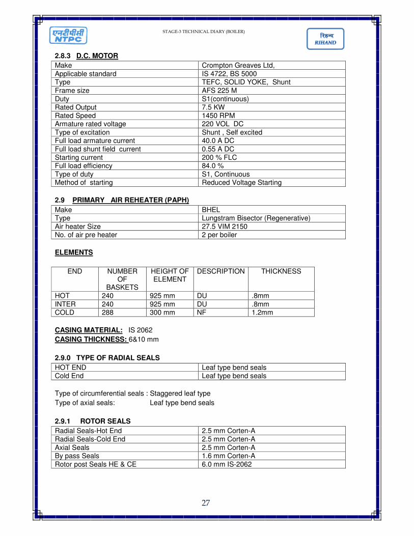
2.8.3 D.C. MOTOR
Make Crompton Greaves Ltd,
Applicable standard IS 4722, BS 5000 Type TEFC, SOLID YOKE, Shunt
Frame size AFS 225 M Duty S1(continuous) Rated Output 7.5 KW Rated Speed 1450 RPM Armature rated voltage 220 VOL DC
Type of excitation Shunt , Self excited Full load armature current 40.0 A DC
Full load shunt field current 0.55 A DC Starting current 200 % FLC Full load efficiency 84.0 %
Type of duty S1, Continuous Method of starting Reduced Voltage Starting
2.9 PRIMARY AIR REHEATER (PAPH)
Make BHEL Type Lungstram Bisector (Regenerative)
Air heater Size 27.5 VIM 2150 No. of air pre heater 2 per boiler
ELEMENTS
END NUMBER OF
BASKETS
HEIGHT OF ELEMENT
DESCRIPTION THICKNESS
HOT 240 925 mm DU .8mm
INTER 240 925 mm DU .8mm COLD 288 300 mm NF 1.2mm
CASING MATERIAL: IS 2062
CASING THICKNESS: 6&10 mm
2.9.0 TYPE OF RADIAL SEALS
HOT END Leaf type bend seals Cold End Leaf type bend seals
Type of circumferential seals : Staggered leaf type
Type of axial seals: Leaf type bend seals
2.9.1 ROTOR SEALS
Radial Seals-Hot End 2.5 mm Corten-A Radial Seals-Cold End 2.5 mm Corten-A
Axial Seals 2.5 mm Corten-A By pass Seals 1.6 mm Corten-A
Rotor post Seals HE & CE 6.0 mm IS-2062

STAGE-3 TECHNICAL DIARY (BOILER)
28
2.9.2 ROTOR DRIVE ASSEMBLY
Electric Motor Squirrel cage, Induction motor (415 V,3�, 50Hz )
Motor Rating 11 KW Motor speed 1460 RPM
Frame & class 160L& F Speed reducer Type- ID. 3 Input, up shaft, M/s Shanthi Gears
Limited Speed ratio Fluid coupling 11.5 FCU- M/S Pembril/T12/04- M/s Fluidomat Final speed
2.9.3 AUXILIARY DRIVE
Air M/s IngersolRand,IR92RA014,5.51:1 Motor Coupling M/S Bibbly coupling type 124 A Solenoid valve 230 V,1 PH,AC, 50 Hz,-1 “BSP
Pressure Switch 1/4" NPT (F), 0-10 Kg/cm2 Filter & Lubricator 1 “BSP
2.9.4 Rotor stoppage Alarm
Go switch M/s Smart Technologies/New Delhi
2.9.5 BEARINGS
Support Bearing Sph. Roller thrust bearing SKF 294/500 E
Guide Bering Sph. Roller bearing (23060/CCK/C3/W33)
RTD 1 “BSP (M) Duplex -thermo well
2.9.6 OIL CIRCULATION SYSTEM
Motor guide & support bearing 0.75 KW, 415 V, 3�,50 Hz,1500 RPM Type Screw Pump Pump Tushaco Delta,model:T3S-25/46 John Type of lubrication Sump oil
Filter Fowler/hp values-15 LPM Cooler M/s Patel Air Temp Ltd.
Coupling Love Joy-L-095 Pr. Gauge with needle valve M20 X1.5; 0-10 Kg/cm2 Flow switch Universal flow monitors
Dial thermometer with well 3/4" BSP 0-100 ° c
2.9.7 DELUGE AND WATER WASHING
Pressure Gauge M20 X1.5; 0-10 KG/CM2
STAGE-3 TECHNICAL DIARY (BOILER)
29
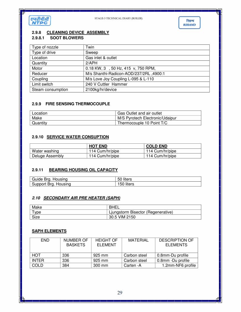
2.9.8 CLEANING DEVICE ASSEMBLY
2.9.8.1 SOOT BLOWERS
Type of nozzle Twin
Type of drive Sweep
Location Gas inlet & outlet
Quantity 2/APH
Motor 0.18 KW, 3�, 50 Hz, 415 v, 750 RPM,
Reducer M/s Shanthi-Radicon-AOD/237/2RL ,4900:1
Coupling M/s Love Joy Coupling L-095 & L-110
Limit switch 240 V Cuttler Hammer
Steam consumption 2100kg/hr/device
2.9.9 FIRE SENSING THERMOCOUPLE
Location Gas Outlet and air outlet Make M/S Pyrotech Electronic/Udaipur
Quantity Thermocouple 10 Point T/C
2.9.10 SERVICE WATER CONSUPTION
HOT END COLD END Water washing 114 Cum/hr/pipe 114 Cum/hr/pipe Deluge Assembly 114 Cum/hr/pipe 114 Cum/hr/pipe
2.9.11 BEARING HOUSING OIL CAPACITY
Guide Brg. Housing 50 liters Support Brg. Housing 150 liters
2.10 SECONDARY AIR PRE HEATER (SAPH)
Make BHEL Type Ljungstorm Bisector (Regenerative) Size 30.5 VIM 2150
SAPH ELEMENTS
END NUMBER OF BASKETS
HEIGHT OF ELEMENT
MATERIAL DESCRIPTION OF ELEMENTS
HOT 336 925 mm Carbon steel 0.8mm-Du profile
INTER 336 925 mm Carbon steel 0.8mm -Du profile
COLD 384 300 mm Carten -A 1.2mm-NF6 profile
STAGE-3 TECHNICAL DIARY (BOILER)
30
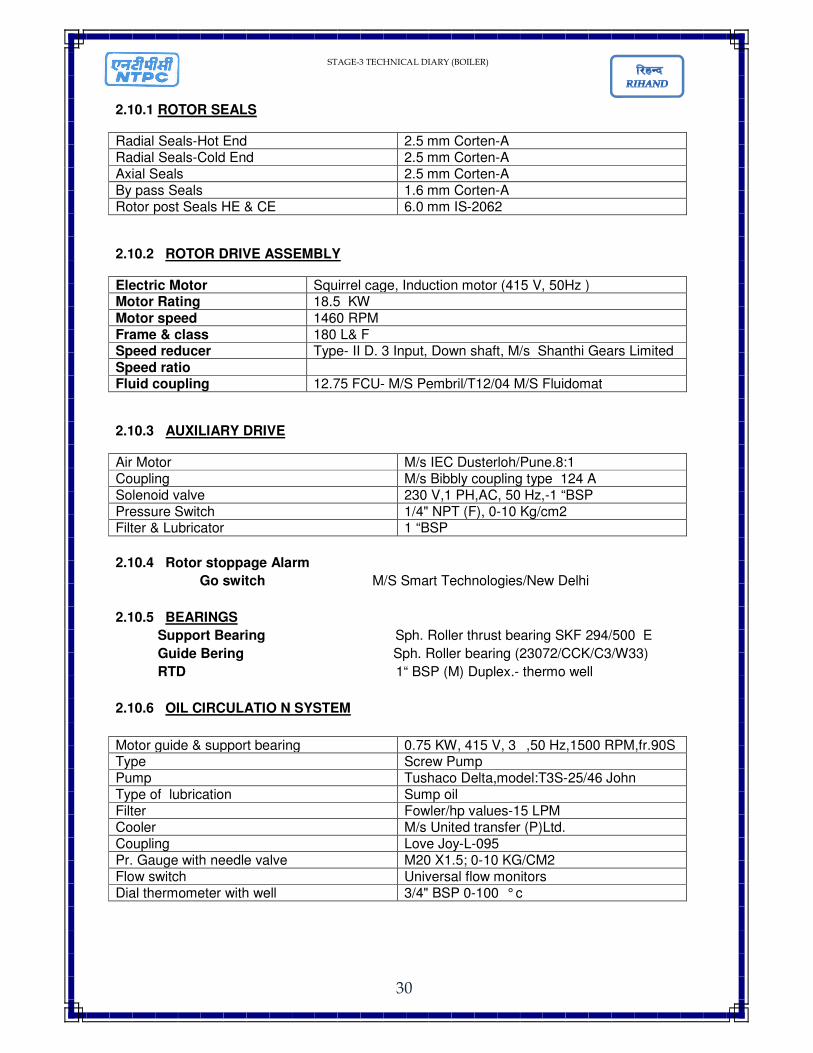
2.10.1 ROTOR SEALS
Radial Seals-Hot End 2.5 mm Corten-A Radial Seals-Cold End 2.5 mm Corten-A Axial Seals 2.5 mm Corten-A By pass Seals 1.6 mm Corten-A Rotor post Seals HE & CE 6.0 mm IS-2062
2.10.2 ROTOR DRIVE ASSEMBLY
Electric Motor Squirrel cage, Induction motor (415 V, 50Hz ) Motor Rating 18.5 KW
Motor speed 1460 RPM Frame & class 180 L& F Speed reducer Type- II D. 3 Input, Down shaft, M/s Shanthi Gears Limited
Speed ratio Fluid coupling 12.75 FCU- M/S Pembril/T12/04 M/S Fluidomat
2.10.3 AUXILIARY DRIVE
Air Motor M/s IEC Dusterloh/Pune.8:1 Coupling M/s Bibbly coupling type 124 A Solenoid valve 230 V,1 PH,AC, 50 Hz,-1 “BSP Pressure Switch 1/4" NPT (F), 0-10 Kg/cm2 Filter & Lubricator 1 “BSP
2.10.4 Rotor stoppage Alarm
Go switch M/S Smart Technologies/New Delhi
2.10.5 BEARINGS
Support Bearing Sph. Roller thrust bearing SKF 294/500 E
Guide Bering Sph. Roller bearing (23072/CCK/C3/W33)
RTD 1“ BSP (M) Duplex.- thermo well
2.10.6 OIL CIRCULATIO N SYSTEM
Motor guide & support bearing 0.75 KW, 415 V, 3�,50 Hz,1500 RPM,fr.90S Type Screw Pump Pump Tushaco Delta,model:T3S-25/46 John Type of lubrication Sump oil Filter Fowler/hp values-15 LPM Cooler M/s United transfer (P)Ltd. Coupling Love Joy-L-095 Pr. Gauge with needle valve M20 X1.5; 0-10 KG/CM2 Flow switch Universal flow monitors Dial thermometer with well 3/4" BSP 0-100 ° c
STAGE-3 TECHNICAL DIARY (BOILER)
31
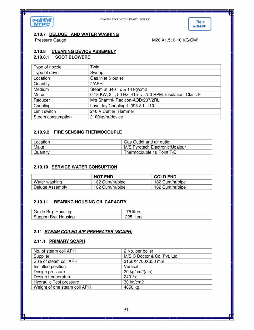
2.10.7 DELUGE AND WATER WASHING
Pressure Gauge M20 X1.5; 0-10 KG/CM2
2.10.8 CLEANING DEVICE ASSEMBLY
2.10.8.1 SOOT BLOWERS
Type of nozzle Twin
Type of drive Sweep
Location Gas inlet & outlet
Quantity 2/APH
Medium Steam at 340 ° c & 14 kg/cm2 Motor 0.18 KW, 3�, 50 Hz, 415 v, 750 RPM, Insulation Class-F
Reducer M/s Shanthi- Radicon-AOD/237/2RL
Coupling Love Joy Coupling L-095 & L-110
Limit switch 240 V Cuttler Hammer
Steem consumption 2100kg/hr/device
2.10.9.2 FIRE SENSING THERMOCOUPLE
Location Gas Outlet and air outlet Make M/S Pyrotech Electronic/Udaipur Quantity Thermocouple 10 Point T/C
2.10.10 SERVICE WATER CONSUPTION
HOT END COLD END Water washing 182 Cum/hr/pipe 182 Cum/hr/pipe
Deluge Assembly 182 Cum/hr/pipe 182 Cum/hr/pipe
2.10.11 BEARING HOUSING OIL CAPACITY
Guide Brg. Housing 75 liters Support Brg. Housing 225 liters
2.11 STEAM COILED AIR PREHEATER (SCAPH)
2.11.1 PRIMARY SCAPH
No. of steam coil APH 2 No. per boiler Supplier M/S C Doctor & Co. Pvt. Ltd.
Size of steam coil APH 3150X4700X350 mm Installed position Vertical Design pressure 20 kg/cm2(ata) Design temperature 240 ° c Hydraulic Test pressure 30 kg/cm2 Weight of one steam coil APH 4650 kg.
STAGE-3 TECHNICAL DIARY (BOILER)
32
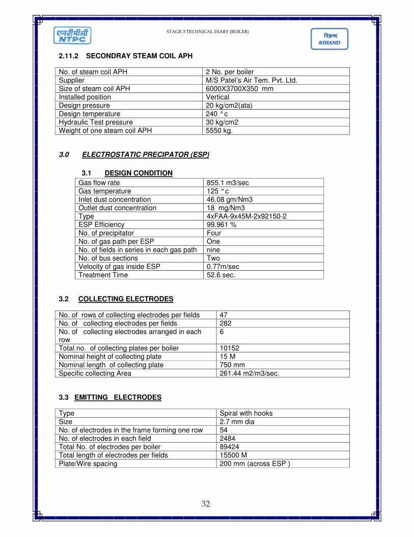
2.11.2 SECONDRAY STEAM COIL APH
No. of steam coil APH 2 No. per boiler Supplier M/S Patel’s Air Tem. Pvt. Ltd. Size of steam coil APH 6000X3700X350 mm Installed position Vertical Design pressure 20 kg/cm2(ata) Design temperature 240 ° c Hydraulic Test pressure 30 kg/cm2 Weight of one steam coil APH 5550 kg.
3.0 ELECTROSTATIC PRECIPATOR (ESP)
3.1 DESIGN CONDITION
Gas flow rate 855.1 m3/sec Gas temperature 125 ° c Inlet dust concentration 46.08 gm/Nm3 Outlet dust concentration 18 mg/Nm3 Type 4xFAA-9x45M-2x92150-2 ESP Efficiency 99.961 %
No. of precipitator Four No. of gas path per ESP One No. of fields in series in each gas path nine No. of bus sections Two Velocity of gas inside ESP 0.77m/sec Treatment Time 52.6 sec.
3.2 COLLECTING ELECTRODES
No. of rows of collecting electrodes per fields 47 No. of collecting electrodes per fields 282 No. of collecting electrodes arranged in each row
6
Total no. of collecting plates per boiler 10152 Nominal height of collecting plate 15 M Nominal length of collecting plate 750 mm
Specific collecting Area 261.44 m2/m3/sec.
3.3 EMITTING ELECTRODES
Type Spiral with hooks
Size 2.7 mm dia No. of electrodes in the frame forming one row 54 No. of electrodes in each field 2484 Total No. of electrodes per boiler 89424 Total length of electrodes per fields 15500 M
Plate/Wire spacing 200 mm (across ESP )

STAGE-3 TECHNICAL DIARY (BOILER)
33
3.4 GAS DISTRIBUTION SYSTEM
INLET Type & quantity Perforated-(3 screen arrangement) with GD
rapping system 1 set.. Location Inlet of Precipitator OUTLET Type & quantity Thin sheets formed to a shape of ”U” located
with 600 mm pitch-one no. Location Outlet of Precipitator
3.5 ELECTRICAL ITEMS
HV RECTIFIER ( BY BHEL BHOPAL/JHANSI) Rating 95 KV DC (Peak) 1000 mA DC (mean) Quantity/ESP 18 Type Silicon oil, Silicon diode, Full wave bridge connection Location Mounted on the roof of ESP
ELECTRONIC CONTROLLER Type of controller Thyristor Quantity/ESP 18 Location In the control room at ground level
BAPCON Microprocessor based TR Controller BAPCON PLUS Quantity/ESP
18
RAPCON Microprocessor based rapper Controller RAPCON 24 /ESP
04
RAPPER CONTROL PANEL Quantity per boiler 8 Equipment controlled Housing RAPCONs along with relay card, data communication
card &buffer cards of all rapping motors
STATCON E Microprocessor based status controller qty per boiler
04
STATCON PANEL
Quantity per Boiler 4 Equipment controlled Housing STATCONs along with data Communication card and
buffer cards.Details of Heaters on/off and Ali status are connected to the controller.
STAGE-3 TECHNICAL DIARY (BOILER)
34
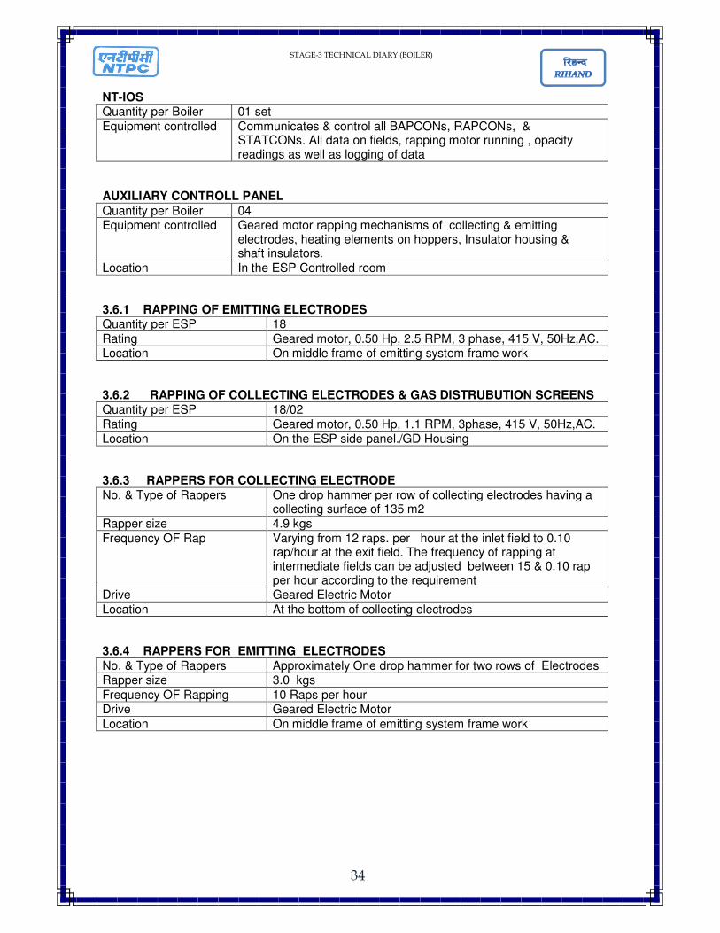
NT-IOS Quantity per Boiler 01 set
Equipment controlled Communicates & control all BAPCONs, RAPCONs, & STATCONs. All data on fields, rapping motor running , opacity readings as well as logging of data
AUXILIARY CONTROLL PANEL
Quantity per Boiler 04 Equipment controlled Geared motor rapping mechanisms of collecting & emitting
electrodes, heating elements on hoppers, Insulator housing & shaft insulators.
Location In the ESP Controlled room
3.6.1 RAPPING OF EMITTING ELECTRODES Quantity per ESP 18
Rating Geared motor, 0.50 Hp, 2.5 RPM, 3 phase, 415 V, 50Hz,AC. Location On middle frame of emitting system frame work
3.6.2 RAPPING OF COLLECTING ELECTRODES & GAS DISTRUBUTION SCREENS Quantity per ESP 18/02 Rating Geared motor, 0.50 Hp, 1.1 RPM, 3phase, 415 V, 50Hz,AC. Location On the ESP side panel./GD Housing
3.6.3 RAPPERS FOR COLLECTING ELECTRODE No. & Type of Rappers One drop hammer per row of collecting electrodes having a
collecting surface of 135 m2 Rapper size 4.9 kgs
Frequency OF Rap Varying from 12 raps. per hour at the inlet field to 0.10 rap/hour at the exit field. The frequency of rapping at intermediate fields can be adjusted between 15 & 0.10 rap per hour according to the requirement
Drive Geared Electric Motor
Location At the bottom of collecting electrodes
3.6.4 RAPPERS FOR EMITTING ELECTRODES No. & Type of Rappers Approximately One drop hammer for two rows of Electrodes Rapper size 3.0 kgs
Frequency OF Rapping 10 Raps per hour Drive Geared Electric Motor
Location On middle frame of emitting system frame work

STAGE-3 TECHNICAL DIARY (BOILER)
35
3.7 HOPPERS
3.7.1 HOPPERS SPECIFICATIONS Type Pyramidal No. of hopper/ESP 36 per pass Heating Panel type heating elements provided at the bottom of hoppers Baffling Arrangement 2 sets of deflector plates for each hopper across the gas flow
direction underneath the collecting plates to prevent the gas sneakage.
3.8 HEATING ELEMEMTS
For Hopper Quantity per ESP 36 Set Type Panel Type
Rating 10 Kw, 1 phase ,415 volt,50 hz Location At the bottom of the hopper Recommended Thermostat setting for heater trip.
120 ° c
For shaft Insulators Quantity per ESP 18 Type Tubular heaters of breathing type Rating 0.1 kw, 1 Phase, 415 AC, 50 Hz Location In the shaft Insulator housing For Support Insulator
Quantity per ESP 72 Type Tubular heaters breathing type Rating 0.1 kw 1 Phase, 415 AC, 50 Hz Location In the support Insulator housing Recommended Thermostat setting for the heater tripping
120 to140 ° c
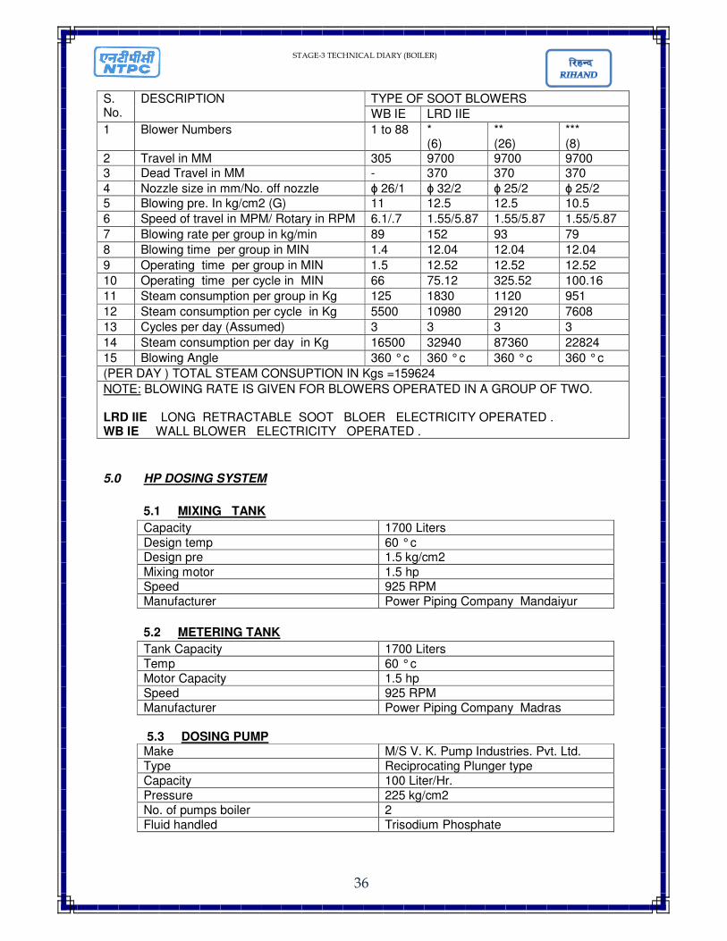
4.0 SOOT BLOWER
Source of steam for soot blowing Tap off from SH Division Outlet Header
Set pressure on pr. Reducing valve 30 kg/cm2 Set pr. On safety valve 40 kg/cm2 (38.4 KSC reset) Maximum flow rate 20 T/Hr Temp after pressure reducing 368 ° c
* ** ***
105 R, 106 L, 109 R, 110 L, 115 R, 116L 107 R, 108L, 111 R-114L, 117R-124L, 133R-144L 125R-132L
STAGE-3 TECHNICAL DIARY (BOILER)
36
S. No.
DESCRIPTION TYPE OF SOOT BLOWERS
WB IE LRD IIE
1 Blower Numbers 1 to 88 * (6)
** (26)
*** (8)
2 Travel in MM 305 9700 9700 9700 3 Dead Travel in MM - 370 370 370
4 Nozzle size in mm/No. off nozzle ɸ 26/1 ɸ 32/2 ɸ 25/2 ɸ 25/2
5 Blowing pre. In kg/cm2 (G) 11 12.5 12.5 10.5
6 Speed of travel in MPM/ Rotary in RPM 6.1/.7 1.55/5.87 1.55/5.87 1.55/5.87
7 Blowing rate per group in kg/min 89 152 93 79
8 Blowing time per group in MIN 1.4 12.04 12.04 12.04
9 Operating time per group in MIN 1.5 12.52 12.52 12.52
10 Operating time per cycle in MIN 66 75.12 325.52 100.16
11 Steam consumption per group in Kg 125 1830 1120 951
12 Steam consumption per cycle in Kg 5500 10980 29120 7608
13 Cycles per day (Assumed) 3 3 3 3
14 Steam consumption per day in Kg 16500 32940 87360 22824
15 Blowing Angle 360 ° c 360 ° c 360 ° c 360 ° c
(PER DAY ) TOTAL STEAM CONSUPTION IN Kgs =159624
NOTE: BLOWING RATE IS GIVEN FOR BLOWERS OPERATED IN A GROUP OF TWO. LRD IIE LONG RETRACTABLE SOOT BLOER ELECTRICITY OPERATED . WB IE WALL BLOWER ELECTRICITY OPERATED .
5.0 HP DOSING SYSTEM
5.1 MIXING TANK
Capacity 1700 Liters
Design temp 60 ° c Design pre 1.5 kg/cm2
Mixing motor 1.5 hp Speed 925 RPM Manufacturer Power Piping Company Mandaiyur
5.2 METERING TANK
Tank Capacity 1700 Liters Temp 60 ° c Motor Capacity 1.5 hp Speed 925 RPM Manufacturer Power Piping Company Madras
5.3 DOSING PUMP Make M/S V. K. Pump Industries. Pvt. Ltd. Type Reciprocating Plunger type Capacity 100 Liter/Hr. Pressure 225 kg/cm2 No. of pumps boiler 2 Fluid handled Trisodium Phosphate
STAGE-3 TECHNICAL DIARY (BOILER)
37
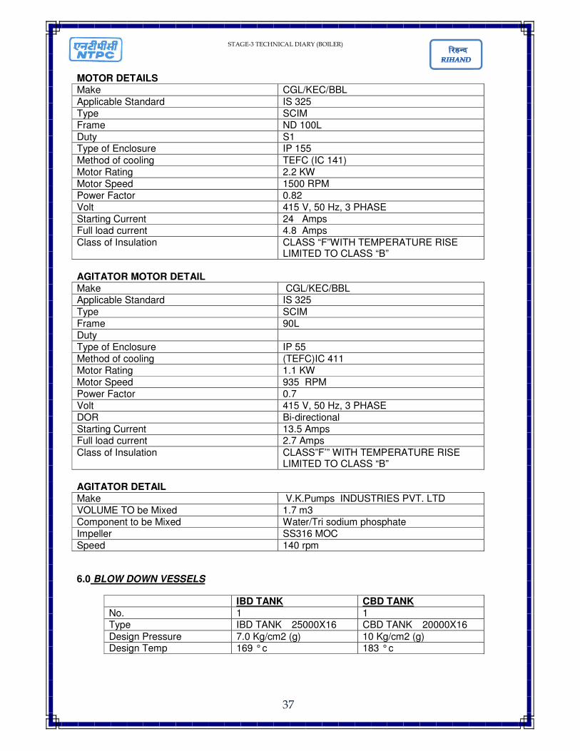
MOTOR DETAILS Make CGL/KEC/BBL
Applicable Standard IS 325 Type SCIM Frame ND 100L Duty S1 Type of Enclosure IP 155
Method of cooling TEFC (IC 141) Motor Rating 2.2 KW Motor Speed 1500 RPM Power Factor 0.82 Volt 415 V, 50 Hz, 3 PHASE Starting Current 24 Amps Full load current 4.8 Amps
Class of Insulation CLASS “F”WITH TEMPERATURE RISE LIMITED TO CLASS “B”
AGITATOR MOTOR DETAIL Make CGL/KEC/BBL Applicable Standard IS 325
Type SCIM Frame 90L Duty Type of Enclosure IP 55 Method of cooling (TEFC)IC 411 Motor Rating 1.1 KW Motor Speed 935 RPM Power Factor 0.7 Volt 415 V, 50 Hz, 3 PHASE DOR Bi-directional Starting Current 13.5 Amps Full load current 2.7 Amps
Class of Insulation CLASS”F’” WITH TEMPERATURE RISE LIMITED TO CLASS “B”
AGITATOR DETAIL Make V.K.Pumps INDUSTRIES PVT. LTD VOLUME TO be Mixed 1.7 m3 Component to be Mixed Water/Tri sodium phosphate Impeller SS316 MOC Speed 140 rpm
6.0 BLOW DOWN VESSELS
IBD TANK CBD TANK
No. 1 1 Type IBD TANK �25000X16 CBD TANK �20000X16
Design Pressure 7.0 Kg/cm2 (g) 10 Kg/cm2 (g) Design Temp 169 ° c 183 ° c
STAGE-3 TECHNICAL DIARY (BOILER)
38
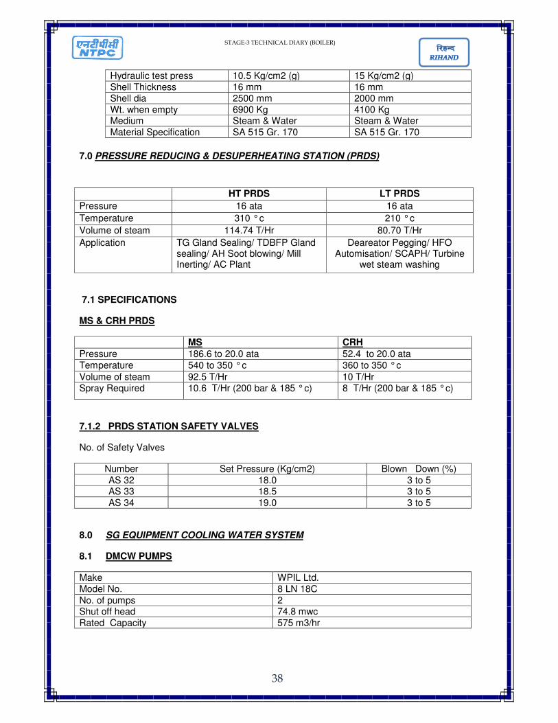
Hydraulic test press 10.5 Kg/cm2 (g) 15 Kg/cm2 (g) Shell Thickness 16 mm 16 mm Shell dia 2500 mm 2000 mm Wt. when empty 6900 Kg 4100 Kg Medium Steam & Water Steam & Water
Material Specification SA 515 Gr. 170 SA 515 Gr. 170
7.0 PRESSURE REDUCING & DESUPERHEATING STATION (PRDS)
7.1 SPECIFICATIONS
MS & CRH PRDS
MS CRH
Pressure 186.6 to 20.0 ata 52.4 to 20.0 ata
Temperature 540 to 350 ° c 360 to 350 ° c
Volume of steam 92.5 T/Hr 10 T/Hr Spray Required 10.6 T/Hr (200 bar & 185 ° c) 8 T/Hr (200 bar & 185 ° c)
7.1.2 PRDS STATION SAFETY VALVES
No. of Safety Valves
Number Set Pressure (Kg/cm2) Blown Down (%)
AS 32 18.0 3 to 5 AS 33 18.5 3 to 5
AS 34 19.0 3 to 5
8.0 SG EQUIPMENT COOLING WATER SYSTEM
8.1 DMCW PUMPS
Make WPIL Ltd. Model No. 8 LN 18C
No. of pumps 2 Shut off head 74.8 mwc
Rated Capacity 575 m3/hr
HT PRDS LT PRDS
Pressure 16 ata 16 ata
Temperature 310 ° c 210 ° c
Volume of steam 114.74 T/Hr 80.70 T/Hr
Application TG Gland Sealing/ TDBFP Gland sealing/ AH Soot blowing/ Mill Inerting/ AC Plant
Deareator Pegging/ HFO Automisation/ SCAPH/ Turbine
wet steam washing
STAGE-3 TECHNICAL DIARY (BOILER)
39
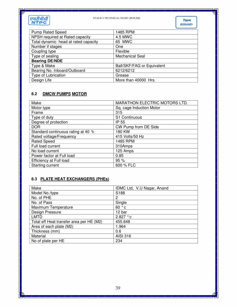
Pump Rated Speed 1485 RPM NPSH required at Rated capacity 4.5 MWC Total dynamic head at rated capacity 65 MWC Number if stages One Coupling type Flexible
Type of sealing Mechanical Seal Bearing DE/NDE Type & Make Ball/SKF/FAG or Equivalent Bearing No. Inboard/Outboard 6212/6212 Type of Lubrication Grease
Design Life More than 40000 Hrs.
8.2 DMCW PUMPS MOTOR
Make MARATHON ELECTRIC MOTORS LTD. Motor type Sq. cage Induction Motor Frame 315 Type of duty S1 Continuous Degree of protection IP 55
DOR CW Pump from DE Side Standard continuous rating at 40 °c 180 KW Rated voltage/Frequency 415 Volts/50 Hz Rated Speed 1485 RPM Full load current 310Amps No load current 125 Amps Power factor at Full load 0.85 Efficiency at Full load 95 % Starting current 600 % FLC
8.3 PLATE HEAT EXCHANGERS (PHEs)
Make IDMC Ltd, V.U Nagar, Anand Model No./type S188 No. of PHE 2
No. of Pass Single Maximum Temperature 60 ° c
Design Pressure 12 bar LMTD 2.827 ° c Total eff Heat transfer area per HE (M2) 455.648
Area of each plate (M2) 1.964 Thickness (mm) 0.6
Material AISI 316 No of plate per HE 234
STAGE-3 TECHNICAL DIARY (BOILER)
40
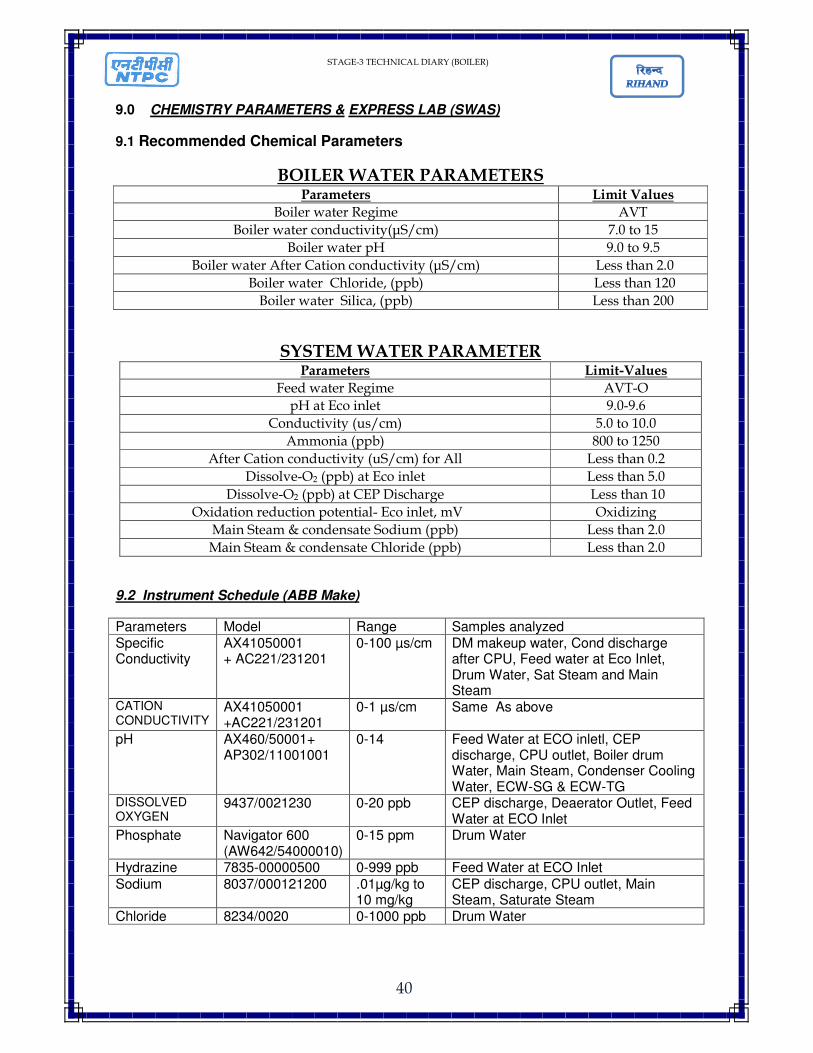
9.0 CHEMISTRY PARAMETERS & EXPRESS LAB (SWAS)
9.1 Recommended Chemical Parameters
BOILER WATER PARAMETERS Parameters Limit Values
Boiler water Regime AVT
Boiler water conductivity(µS/cm) 7.0 to 15
Boiler water pH 9.0 to 9.5
Boiler water After Cation conductivity (µS/cm) Less than 2.0
Boiler water Chloride, (ppb) Less than 120
Boiler water Silica, (ppb) Less than 200
SYSTEM WATER PARAMETER Parameters Limit-Values
Feed water Regime AVT-O
pH at Eco inlet 9.0-9.6
Conductivity (us/cm) 5.0 to 10.0
Ammonia (ppb) 800 to 1250
After Cation conductivity (uS/cm) for All Less than 0.2
Dissolve-O2 (ppb) at Eco inlet Less than 5.0
Dissolve-O2 (ppb) at CEP Discharge Less than 10
Oxidation reduction potential- Eco inlet, mV Oxidizing
Main Steam & condensate Sodium (ppb) Less than 2.0
Main Steam & condensate Chloride (ppb) Less than 2.0
9.2 Instrument Schedule (ABB Make)
Parameters Model Range Samples analyzed Specific Conductivity
AX41050001 + AC221/231201
0-100 µs/cm DM makeup water, Cond discharge after CPU, Feed water at Eco Inlet, Drum Water, Sat Steam and Main Steam
CATION CONDUCTIVITY
AX41050001 +AC221/231201
0-1 µs/cm Same As above
pH AX460/50001+ AP302/11001001
0-14 Feed Water at ECO inletl, CEP discharge, CPU outlet, Boiler drum Water, Main Steam, Condenser Cooling Water, ECW-SG & ECW-TG
DISSOLVED OXYGEN
9437/0021230 0-20 ppb CEP discharge, Deaerator Outlet, Feed Water at ECO Inlet
Phosphate Navigator 600 (AW642/54000010)
0-15 ppm Drum Water
Hydrazine 7835-00000500 0-999 ppb Feed Water at ECO Inlet
Sodium 8037/000121200 .01µg/kg to 10 mg/kg
CEP discharge, CPU outlet, Main Steam, Saturate Steam
Chloride 8234/0020 0-1000 ppb Drum Water
STAGE-3 TECHNICAL DIARY (BOILER)
41
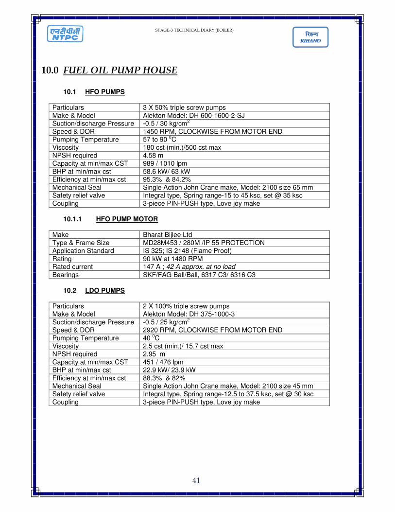
10.0 FUEL OIL PUMP HOUSE
10.1 HFO PUMPS
Particulars 3 X 50% triple screw pumps
Make & Model Alekton Model: DH 600-1600-2-SJ Suction/discharge Pressure -0.5 / 30 kg/cm2
Speed & DOR 1450 RPM, CLOCKWISE FROM MOTOR END Pumping Temperature 57 to 90 0C Viscosity 180 cst (min.)/500 cst max NPSH required 4.58 m Capacity at min/max CST 989 / 1010 lpm
BHP at min/max cst 58.6 kW/ 63 kW Efficiency at min/max cst 95.3% & 84.2% Mechanical Seal Single Action John Crane make, Model: 2100 size 65 mm Safety relief valve Integral type, Spring range-15 to 45 ksc, set @ 35 ksc Coupling 3-piece PIN-PUSH type, Love joy make
10.1.1 HFO PUMP MOTOR
Make Bharat Bijlee Ltd Type & Frame Size MD28M453 / 280M /IP 55 PROTECTION Application Standard IS 325; IS 2148 (Flame Proof)
Rating 90 kW at 1480 RPM Rated current 147 A ; 42 A approx. at no load
Bearings SKF/FAG Ball/Ball, 6317 C3/ 6316 C3
10.2 LDO PUMPS
Particulars 2 X 100% triple screw pumps Make & Model Alekton Model: DH 375-1000-3
Suction/discharge Pressure -0.5 / 25 kg/cm2 Speed & DOR 2920 RPM, CLOCKWISE FROM MOTOR END Pumping Temperature 40 0C
Viscosity 2.5 cst (min.)/ 15.7 cst max NPSH required 2.95 m
Capacity at min/max CST 451 / 476 lpm BHP at min/max cst 22.9 kW/ 23.9 kW
Efficiency at min/max cst 88.3% & 82% Mechanical Seal Single Action John Crane make, Model: 2100 size 45 mm Safety relief valve Integral type, Spring range-12.5 to 37.5 ksc, set @ 30 ksc
Coupling 3-piece PIN-PUSH type, Love joy make

STAGE-3 TECHNICAL DIARY (BOILER)
42
10.2.1 LDO PUMP MOTOR
Make Bharat Bijlee Ltd Type & Frame Size MD20L253 / 200L /IP 55 PROTECTION
Application Standard IS 325; IS 2148 (Flame Proof) Rating 37 kW at 2955 RPM Rated current 62.9 A ; 20 A approx. at no load
Bearings SKF/FAG Ball/Ball, 6212 C3/ 6212 C3
10.3 HFO HEATER & DRAIN OIL COOLER
HEATER COOLER Nos 03 02 Surface Area 50 sq M Type Oil in shell, Water in U-tube Oil in shell, Water in U-tube Design Press (HFO side) 32 ksc Design Press (Steam side) 24 ksc
10.4 HFO DRAIN OIL PUMPS
LOCATION: One in Pump House, one each at boiler zero meter-both units. Nos. 3
Pump Type Internal Gear Pump to handle LDO/HFO/LSHS at temp range-57 to 1200C
Make & Model Tushaco Pumps- R20-DG Rating 67 to 71 LPM at 10 ksc, Suction pr.-(-)0.5 ksc
Rotation 1445 RPM, clockwise as seen from motor end. Pump Motor CGL make 5.5 kW SCIM
Coupling Love Joy- RC 042
10.5 HFO SUMP PUMP (PUMP HOUSE)
Nos. 2 (1 working) Pump type Vertical submerged to handle HFO/sludge
Make & Model Sam Turbo, VO 32/200+ CPC Size & Rating 50x32 (SuctionX discharge), 10 m3/hr at 53 m total head
Pump Motor Marathon make 5.5 Kw @2900 RPM SCIM Coupling SAM make Pin & Bush Bushes Total-03 nos, CFT (Carbon filled Teflon) bearings
Lubrication External with Clear water
STAGE-3 TECHNICAL DIARY (BOILER)
43
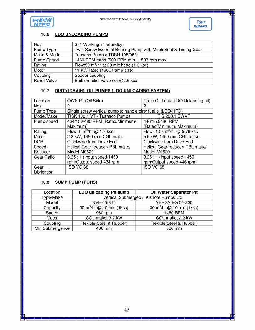
10.6 LDO UNLOADING PUMPS
Nos 2 (1 Working +1 Standby) Pump Type Twin Screw External Bearing Pump with Mech Seal & Timing Gear
Make & Model Tushaco Pumps: TDSH 105/058 Pump Speed 1460 RPM rated (500 RPM min.- 1533 rpm max) Rating Flow:50 m3/hr at 20 mlc head (1.6 ksc) Motor 11 KW rated (160L frame size) Coupling Spacer coupling Relief Valve Built on relief valve set @2.6 ksc
10.7 DIRTY(DRAIN) OIL PUMPS (LDO UNLOADING SYSTEM) Location OWS Pit (Oil Side) Drain Oil Tank (LDO Unloading pit) Nos 2 2 Pump Type Single screw vertical pump to handle dirty fuel oil(LDO/HFO) Model/Make TISK 100.1 VT / Tushaco Pumps TIS 200.1 EWVT Pump speed 434/150/480 RPM (Rated/Minimum/
Maximum) 446/150/480 RPM (Rated/Minimum/ Maximum)
Rating Flow- 6 m3/hr @ 1.8 ksc Flow- 10.8 m3/hr @ 5.76 ksc Motor 2.2 kW, 1450 rpm CGL make 5.5 kW, 1450 rpm CGL make DOR Clockwise from Drive End Clockwise from Drive End Speed Reducer
Helical Gear reducer/ PBL make/ Model-M0620
Helical Gear reducer/ PBL make/ Model-M0620
Gear Ratio 3.25 : 1 (Input speed-1450 rpm/Output speed-434 rpm)
3.25 : 1 (Input speed-1450 rpm/Output speed-446 rpm)
Gear lubrication
ISO VG 68 ISO VG 68
10.8 SUMP PUMP (FOHS)
Location LDO unloading Pit sump Oil Water Separator Pit
Type/Make Vertical Submerged / Kishore Pumps Ltd Model NVE 65-315 VERSA EG 50-200
Capacity 30 m3/hr @ 10 mlc (1ksc) 30 m3/hr @ 10 mlc (1ksc)
Speed 960 rpm 1450 RPM Motor CGL make, 3.7 kW CGL make, 2.2 kW
Coupling Flexible(Steel & Rubber) Flexible(Steel & Rubber) Min Submergence 400 mm 360 mm
STAGE-3 TECHNICAL DIARY (BOILER)
44
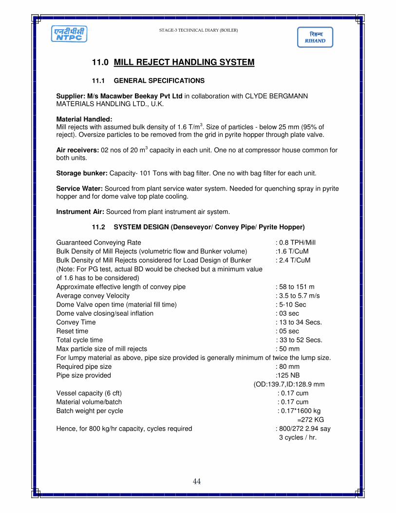
11.0 MILL REJECT HANDLING SYSTEM
11.1 GENERAL SPECIFICATIONS Supplier: M/s Macawber Beekay Pvt Ltd in collaboration with CLYDE BERGMANN MATERIALS HANDLING LTD., U.K. Material Handled: Mill rejects with assumed bulk density of 1.6 T/m3. Size of particles - below 25 mm (95% of reject). Oversize particles to be removed from the grid in pyrite hopper through plate valve. Air receivers: 02 nos of 20 m3 capacity in each unit. One no at compressor house common for both units. Storage bunker: Capacity- 101 Tons with bag filter. One no with bag filter for each unit. Service Water: Sourced from plant service water system. Needed for quenching spray in pyrite hopper and for dome valve top plate cooling. Instrument Air: Sourced from plant instrument air system.
11.2 SYSTEM DESIGN (Denseveyor/ Convey Pipe/ Pyrite Hopper) Guaranteed Conveying Rate : 0.8 TPH/Mill
Bulk Density of Mill Rejects (volumetric flow and Bunker volume) :1.6 T/CuM
Bulk Density of Mill Rejects considered for Load Design of Bunker : 2.4 T/CuM
(Note: For PG test, actual BD would be checked but a minimum value
of 1.6 has to be considered)
Approximate effective length of convey pipe : 58 to 151 m
Average convey Velocity : 3.5 to 5.7 m/s
Dome Valve open time (material fill time) : 5-10 Sec
Dome valve closing/seal inflation : 03 sec
Convey Time : 13 to 34 Secs.
Reset time : 05 sec
Total cycle time : 33 to 52 Secs.
Max particle size of mill rejects : 50 mm
For lumpy material as above, pipe size provided is generally minimum of twice the lump size.
Required pipe size : 80 mm
Pipe size provided :125 NB
(OD:139.7,ID:128.9 mm
Vessel capacity (6 cft) : 0.17 cum
Material volume/batch : 0.17 cum
Batch weight per cycle : 0.17*1600 kg
=272 KG
Hence, for 800 kg/hr capacity, cycles required : 800/272 2.94 say
3 cycles / hr.
STAGE-3 TECHNICAL DIARY (BOILER)
45
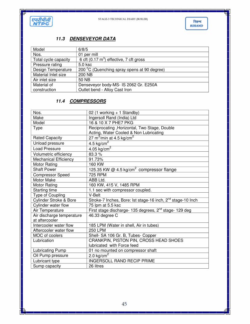
11.3 DENSEVEYOR DATA Model 6/8/5 Nos. 01 per mill Total cycle capacity 6 cft (0.17 m3) effective, 7 cft gross Pressure rating 5.0 ksc Design Temperature 200 0C (Quenching spray opens at 90 degree) Material Inlet size 200 NB Air inlet size 50 NB Material of construction
Denseveyor body-MS- IS 2062 Gr. E250A Outlet bend - Alloy Cast Iron
11.4 COMPRESSORS
Nos. 02 (1 working + 1 Standby)
Make Ingersoll Rand (India) Ltd Model 16 & 10 X 7 PHE7 PKG
Type Reciprocating ,Horizontal, Two Stage, Double Acting, Water Cooled & Non Lubricating
Rated Capacity 27 m3/min at 4.5 kg/cm
2
Unload pressure 4.5 kg/cm2
Load Pressure 4.05 kg/cm2
Volumetric efficiency 83.3 %
Mechanical Efficiency 91.73% Motor Rating 160 KW Shaft Power 125.35 KW @ 4.5 kg/cm
2 compressor flange
Compressor Speed 725 RPM
Motor Make ABB Ltd. Motor Rating 160 KW, 415 V, 1485 RPM Starting time 1.1 sec with compressor coupled. Type of Coupling V-Belt Cylinder Stroke & Bore Stroke-7 Inches, Bore: Ist stage-16 inch, 2nd stage-10 Inch Cylinder water flow 75 lpm at 5.5 ksc Air Temperature First stage discharge- 135 degrees, 2nd stage- 129 deg
Air discharge temperature at aftercooler
46.33 degree C
Intercooler water flow 185 LPM (Water in shell, Air in tubes) Aftercooler water flow 250 LPM
MOC of coolers Shell- SA 106 Gr. B, Tubes- Copper Lubrication CRANKPIN, PISTON PIN, CROSS HEAD SHOES
lubricated with Force feed Lubricating Pump 01 no mounted on compressor shaft Oil Pump pressure 2.0 kg/cm
2 Lubricant type INGERSOLL RAND RECIP PRIME
Sump capacity 26 litres