microlectra bv. [email protected]
TRANSCRIPT

M2MBOXPRO - INDUSTRIAL GATEWAY
USER MANUAL REV0.2
www.microlectra.nl Microlectra bv. [email protected]
Microlectra bv.Hermanus Boerhaavestraat 6. 3261 ME Oud-Beijerland. Netherlands.
Tel 31(0)186-616290 Fax 31(0)186-610349 www.microlectra.nl [email protected]
Revision history
Rev. Date Details Originated by0.1 24 June 2010 First issue Pierre-Emmanuel Surga0.2 05 August 2010 I²C interface details, regulatory details Pierre-Emmauel Surga
This manual is written without any warranty.
Maestro Wireless Solutions Ltd. reserves the right to modify or improve the product and its accessorieswhich can also be withdrawn without prior notice.
Besides, our company stresses the fact that the performance of the product as well as accessories dependsnot only on the proper conditions of use, but also on the environment around the places of use.
Maestro Wireless Solutions Ltd. assumes no liability for damage incurred directly or indirectly from errors,omissions or discrepancies between the modem and the manual.
Confidential, the whole document is the sole property of Maestro Wireless Solutions ltd. 1
Microlectra bv.
Contents
1 Description 5
1.1 Package . . . . . . . . . . . . . . . . . . . . . . . . . . . . . . . . . . . . . . . . . . . . . . . . . 5
1.2 Interfaces . . . . . . . . . . . . . . . . . . . . . . . . . . . . . . . . . . . . . . . . . . . . . . . . 5
1.2.1 Serial port 1 . . . . . . . . . . . . . . . . . . . . . . . . . . . . . . . . . . . . . . . . . . . 6
1.2.2 Serial port 2 . . . . . . . . . . . . . . . . . . . . . . . . . . . . . . . . . . . . . . . . . . . 7
1.2.3 Ethernet . . . . . . . . . . . . . . . . . . . . . . . . . . . . . . . . . . . . . . . . . . . . 7
1.2.4 Audio . . . . . . . . . . . . . . . . . . . . . . . . . . . . . . . . . . . . . . . . . . . . . . 8
1.2.5 USB console . . . . . . . . . . . . . . . . . . . . . . . . . . . . . . . . . . . . . . . . . . 8
1.2.6 Power input . . . . . . . . . . . . . . . . . . . . . . . . . . . . . . . . . . . . . . . . . . 8
1.2.7 Battery . . . . . . . . . . . . . . . . . . . . . . . . . . . . . . . . . . . . . . . . . . . . . 9
1.2.8 Digital inputs . . . . . . . . . . . . . . . . . . . . . . . . . . . . . . . . . . . . . . . . . . 9
1.2.9 I²C port . . . . . . . . . . . . . . . . . . . . . . . . . . . . . . . . . . . . . . . . . . . . . 9
1.2.10 Analog Inputs . . . . . . . . . . . . . . . . . . . . . . . . . . . . . . . . . . . . . . . . . 10
1.2.11 Digital Outputs . . . . . . . . . . . . . . . . . . . . . . . . . . . . . . . . . . . . . . . . . 10
1.2.12 LEDs and buttons . . . . . . . . . . . . . . . . . . . . . . . . . . . . . . . . . . . . . . . 11
1.2.13 Battery slot . . . . . . . . . . . . . . . . . . . . . . . . . . . . . . . . . . . . . . . . . . . 11
1.2.14 SIM holder . . . . . . . . . . . . . . . . . . . . . . . . . . . . . . . . . . . . . . . . . . . 11
1.2.15 Hardware configuration DIP switches . . . . . . . . . . . . . . . . . . . . . . . . . . . . 11
2 Installation 13
2.1 Inserting SIM card and battery . . . . . . . . . . . . . . . . . . . . . . . . . . . . . . . . . . . . 13
2.2 Mounting the M2MBoxPro . . . . . . . . . . . . . . . . . . . . . . . . . . . . . . . . . . . . . . . 13
2.3 Connect the external antenna (SMA type) . . . . . . . . . . . . . . . . . . . . . . . . . . . . . . 13
2.4 Connect the modem to external device . . . . . . . . . . . . . . . . . . . . . . . . . . . . . . . . 14
2.5 Connect the DC power supply . . . . . . . . . . . . . . . . . . . . . . . . . . . . . . . . . . . . . 14
Confidential, the whole document is the sole property of Maestro Wireless Solutions ltd. 2
Microlectra bv.
3 Hardware block diagram 15
Confidential, the whole document is the sole property of Maestro Wireless Solutions ltd. 3
Microlectra bv.
Microlectra bv.Hermanus Boerhaavestraat 6. 3261 ME Oud-Beijerland. Netherlands.
Tel 31(0)186-616290 Fax 31(0)186-610349 www.microlectra.nl [email protected]
Safety precautions
General precautions
– The modem generates radio frequency (RF) power. When using the modem care must be taken onsafety issues related to RF interference as well as regulations of RF equipment.
– Do not use your phone in aircraft, hospitals, petrol stations or in places where using GSM products isprohibited.
– Be sure that the modem will not be interfering with nearby equipment. For example: pacemakers ormedical equipment. The antenna of the modem should be away from computers, office equipment,home appliance, etc.
– An external antenna must be connected to the modem for proper operation. Only used approved anten-nas with the modem. Please contact authorized dealer on finding an approved antenna.
– Always keep the antenna with minimum safety distance of 26.6 cm or more
Protecting your modem
– To ensure error-free usage, please install and operate your modem with care. Do remember the follow-ing:
– Do not expose the modem to extreme conditions such as high humidity/rain, high temperatures, directsunlight, caustic/harsh chemicals, dust, or water.
– Do not try to disassemble or modify the modem. There is no user serviceable part inside and thewarranty would be void.
– Do not drop, hit or shake the modem. Do not use the modem under extreme vibrating condition.
– Do not pull the antenna or power supply cable. Attach/ detach by holding the connector.
– Connect the modem only according to the instruction manual. Failure to do it will void the warranty.
Confidential, the whole document is the sole property of Maestro Wireless Solutions ltd. 4
Microlectra bv.
Chapter 1
Description
The M2MboxPro is a ready-to-use industrial gateway for voice, data, fax and SMS services. It also supportscellular connectivity (GSM, GPRS) as well as Ethernet, serial ports, USB and various industrial interfaces.The M2MBoxPro can be easily controlled by using AT command for all kinds of operations. It is also fullycustomizable using the Sierra Wireless openAT operating system and development environment to fit variouscustomer applications.
1.1 Package
The M2MBoxPro package should include the following:
– M2MBoxPro x 1
– Power cord with fuse x 1
– Terminal block connectors x 5
– RS232 serial cable x1
– L-shape antenna (linear quad band antenna) x1 1
1.2 Interfaces
1The provided antenna has a gain of 2.0 ± 0.7dBi @ 880 MHz and 1.0 ± 0.7dBi @ 1990 MHz. As per FCC requirements no antennaof a greater gain should be used with the M2MBoxPro. In addition, it is required to always keep a safety distance of 26.6cm or more.
Confidential, the whole document is the sole property of Maestro Wireless Solutions ltd. 5
Microlectra bv.
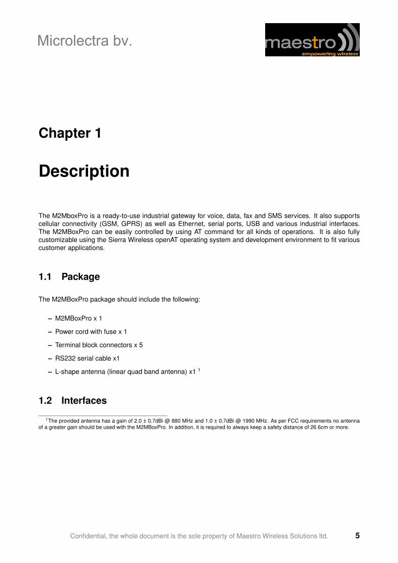
Accessible at the back, after removing safety cover: battery slot, SIM card holder, hardware configuration DIPswitches. Disconnect all wires and cables from the M2MBoxPro before removing the safety cover.
1.2.1 Serial port 1
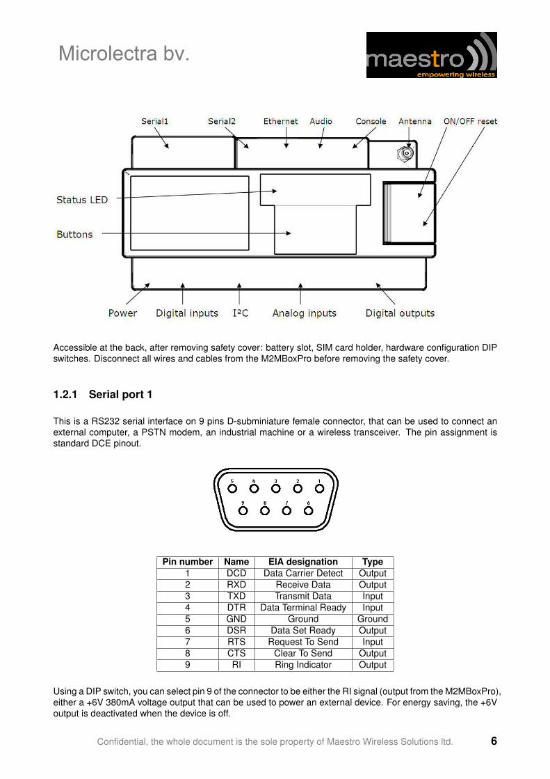
This is a RS232 serial interface on 9 pins D-subminiature female connector, that can be used to connect anexternal computer, a PSTN modem, an industrial machine or a wireless transceiver. The pin assignment isstandard DCE pinout.
Pin number Name EIA designation Type1 DCD Data Carrier Detect Output2 RXD Receive Data Output3 TXD Transmit Data Input4 DTR Data Terminal Ready Input5 GND Ground Ground6 DSR Data Set Ready Output7 RTS Request To Send Input8 CTS Clear To Send Output9 RI Ring Indicator Output
Using a DIP switch, you can select pin 9 of the connector to be either the RI signal (output from the M2MBoxPro),either a +6V 380mA voltage output that can be used to power an external device. For energy saving, the +6Voutput is deactivated when the device is off.
Confidential, the whole document is the sole property of Maestro Wireless Solutions ltd. 6
Microlectra bv.
ESD Protection: ±8kV air discharge
Serial interface 1 is connected to Q26 UART1 interface.
1.2.2 Serial port 2
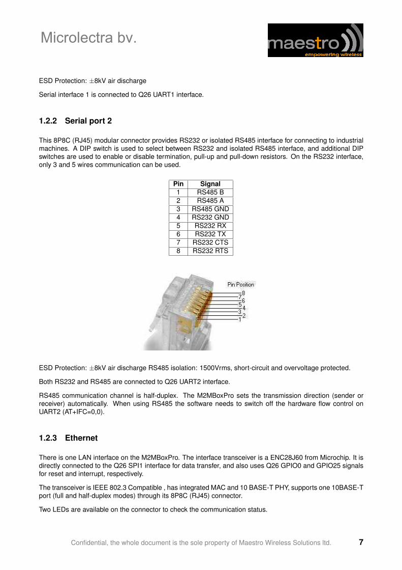
This 8P8C (RJ45) modular connector provides RS232 or isolated RS485 interface for connecting to industrialmachines. A DIP switch is used to select between RS232 and isolated RS485 interface, and additional DIPswitches are used to enable or disable termination, pull-up and pull-down resistors. On the RS232 interface,only 3 and 5 wires communication can be used.
Pin Signal1 RS485 B2 RS485 A3 RS485 GND4 RS232 GND5 RS232 RX6 RS232 TX7 RS232 CTS8 RS232 RTS
ESD Protection: ±8kV air discharge RS485 isolation: 1500Vrms, short-circuit and overvoltage protected.
Both RS232 and RS485 are connected to Q26 UART2 interface.
RS485 communication channel is half-duplex. The M2MBoxPro sets the transmission direction (sender orreceiver) automatically. When using RS485 the software needs to switch off the hardware flow control onUART2 (AT+IFC=0,0).
1.2.3 Ethernet
There is one LAN interface on the M2MBoxPro. The interface transceiver is a ENC28J60 from Microchip. It isdirectly connected to the Q26 SPI1 interface for data transfer, and also uses Q26 GPIO0 and GPIO25 signalsfor reset and interrupt, respectively.
The transceiver is IEEE 802.3 Compatible , has integrated MAC and 10 BASE-T PHY, supports one 10BASE-Tport (full and half-duplex modes) through its 8P8C (RJ45) connector.
Two LEDs are available on the connector to check the communication status.
Confidential, the whole document is the sole property of Maestro Wireless Solutions ltd. 7
Microlectra bv.
1.2.4 Audio
The M2MBoxPro provides a 4P4C connector to connect directly to a phone handset.
The pinout is industry standard:
Pin Signal1 Microphone -2 Speaker -3 Speaker +4 Microphone +
ESD protection:±8kV air discharge TDMA noise reduction and EMC protection. Echo cancellation and noisereduction is done in software by the Q26 module. This interface connects to the Q26 MIC2 and SPK2 signals.MIC1 and SPK1 are not used.
1.2.5 USB console
The M2MBoxPro has a USB interface (labeled as console interface) that connects directly to the Q26 USBinterface. The M2MBoxPro acts as a USB slave device.
– 12Mbit/s full-speed transfer rate
– 3.3V type compatible
– USB Soft connect feature
– Download feature is not supported by USB
– CDC 1.1 − ACM compliant
1.2.6 Power input
The M2MBoxPro takes DC voltage from 9VDC to 28VDC, and is protected against over and reverse voltage.It also has a resettable fuse for increased protection.
Resettable fuse rating: 900mA
There are four ways to turn on the M2MBoxPro:
– press the ON/OFF button for a short period of time
– while the M2MBoxPro is switched off, apply a positive voltage on digital input 0 (this can be deactivatedusing DIP switches)
– while the M2MBoxPro is disconnected and has no battery, connect the mains and apply a voltage be-tween 9V to 28V DC on the power supply input
– use a Wavecom Q26 alarm
To turn off the M2MBoxPro, it is recommended to send the AT+CPOF command to the wireless processor.This can be done either by serial port, either by openAT. Once the device is powered on, the ON/OFF buttoncan be sensed with Q26 GPIO4 signal. It is recommended that the openAT software polls this signal and senda AT+CPOF command after ON/OFF button is pushed for more than 10 seconds.
Confidential, the whole document is the sole property of Maestro Wireless Solutions ltd. 8
Microlectra bv.
1.2.7 Battery
To continue operating when the mains power is cut, the M2MBoxPro embeds a 2000mAh lithium backupbattery. The modem can operate for several days without being recharged.
It is possible for the openAT software to detect whether it is powered by the battery or by the mains by sensingGPIO12: if GPIO12 is high, the M2MBoxPro is powered by the mains. If GPIO12 is low, the device is poweredby the battery.
The battery has a given lifetime of more than 300 charge cycles. It is recommended that the customer appli-cation software uses GPIO12 signal to count the number of charge cycles, so that it can estimate battery endof life.
Note that the M2MBoxPro does not use the Q26’s integrated charging circuit, but an external one. The batteryvoltage can be measured using the Q26’s ADC0 interface.
1.2.8 Digital inputs
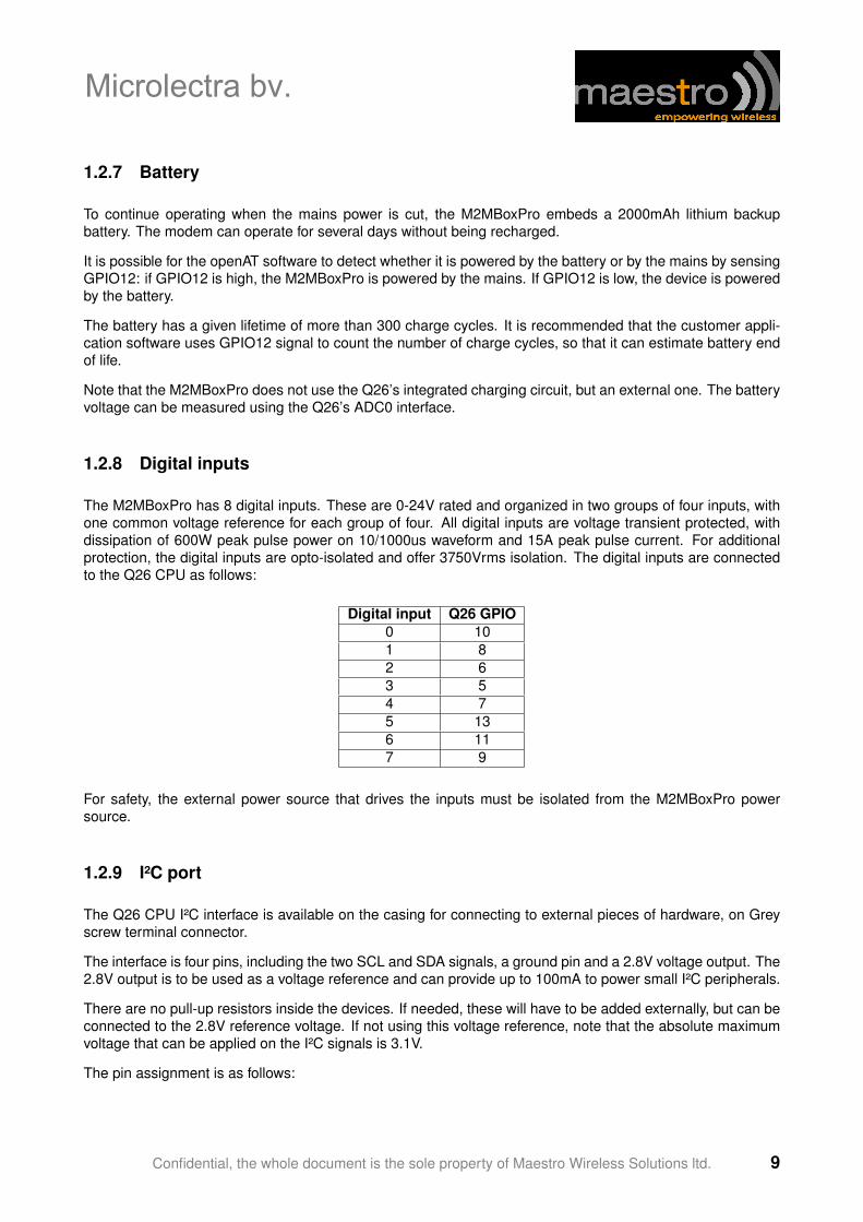
The M2MBoxPro has 8 digital inputs. These are 0-24V rated and organized in two groups of four inputs, withone common voltage reference for each group of four. All digital inputs are voltage transient protected, withdissipation of 600W peak pulse power on 10/1000us waveform and 15A peak pulse current. For additionalprotection, the digital inputs are opto-isolated and offer 3750Vrms isolation. The digital inputs are connectedto the Q26 CPU as follows:
Digital input Q26 GPIO0 101 82 63 54 75 136 117 9
For safety, the external power source that drives the inputs must be isolated from the M2MBoxPro powersource.
1.2.9 I²C port
The Q26 CPU I²C interface is available on the casing for connecting to external pieces of hardware, on Greyscrew terminal connector.
The interface is four pins, including the two SCL and SDA signals, a ground pin and a 2.8V voltage output. The2.8V output is to be used as a voltage reference and can provide up to 100mA to power small I²C peripherals.
There are no pull-up resistors inside the devices. If needed, these will have to be added externally, but can beconnected to the 2.8V reference voltage. If not using this voltage reference, note that the absolute maximumvoltage that can be applied on the I²C signals is 3.1V.
The pin assignment is as follows:
Confidential, the whole document is the sole property of Maestro Wireless Solutions ltd. 9
Microlectra bv.
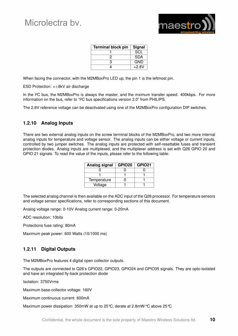
Terminal block pin Signal1 SCL2 SDA3 GND4 +2.8V
When facing the connector, with the M2MBoxPro LED up, the pin 1 is the leftmost pin.
ESD Protection: +±8kV air discharge
In the I²C bus, the M2MBoxPro is always the master, and the mximum transfer speed: 400kbps. For moreinformation on the bus, refer to “I²C bus specifications version 2.0” from PHILIPS.
The 2.8V reference voltage can be deactivated using one of the M2MBoxPro configuration DIP switches.
1.2.10 Analog Inputs
There are two external analog inputs on the screw terminal blocks of the M2MBoxPro, and two more internalanalog inputs for temperature and voltage sensor. The analog inputs can be either voltage or current inputs,controlled by two jumper switches. The analog inputs are protected with self-resettable fuses and transientprotection diodes. Analog inputs are multiplexed, and the multiplexer address is set with Q26 GPIO 20 andGPIO 21 signals. To read the value of the inputs, please refer to the following table:
Analog signal GPIO20 GPIO210 0 01 1 1
Temperature 0 1Voltage 1 1
The selected analog channel is then available on the ADC input of the Q26 processor. For temperature sensorsand voltage sensor specifications, refer to corresponding sections of this document.
Analog voltage range: 0-10V Analog current range: 0-20mA
ADC resolution: 10bits
Protections fuse rating: 80mA
Maximum peak power: 600 Watts (10/1000 ms)
1.2.11 Digital Outputs
The M2MBoxPro features 4 digital open collector outputs.
The outputs are connected to Q26’s GPIO22, GPIO23, GPIO24 and GPIO35 signals. They are opto-isolatedand have an integrated fly-back protection diode
Isolation: 3750Vrms
Maximum base-collector voltage: 160V
Maximum continuous current: 600mA
Maximum power dissipation: 350mW at up to 25°C, derate at 2.8mW/°C above 25°C
Confidential, the whole document is the sole property of Maestro Wireless Solutions ltd. 10
Microlectra bv.
1.2.12 LEDs and buttons
The M2MBoxPro user interface consists of 6 connection LEDs, 3 application LEDs and two user buttons.
The two user buttons are connected to Q26 GPIO 1 and GPIO 2 signals, and are debounced by hardware.There are two additional buttons, one that will instantly cause a reset of the processor (to use only in caseof software crash), and a ON/OFF button whose function is described in the Power Source section of thisdocument).
The three application LEDs are driven by the openAT application or by AT commands: GPIO32 drives theStatus LED, GPIO33 drives the A1 LED and GPIO34 drives the A2 LED.
The connection LEDs are driven by hardware and give insight about the M2MBoxPro interfaces status:
– Power LED: is green when the M2MBoxPro is powered by the mains, and yellow if it is powered by thebattery
– GSM LED: is solid if the M2MBoxPro can’t connect to the cellular network, and is blinking otherwise
– LAN, Serial1, Serial2 and I²C LEDs are flashing when there is activity on their respective interface.
1.2.13 Battery slot
The battery slot is accessible by removing the two philips screws of the battery cover. Disconnect all wires andcables from the M2MBoxPro before removing the safety cover.
Do not use any other battery than the one supplied by Maestro Wireless solutions ltd.
1.2.14 SIM holder
The SIM holder is accessible after removing the battery. Disconnect and remove the battery before you attemptto install or change the SIM card.
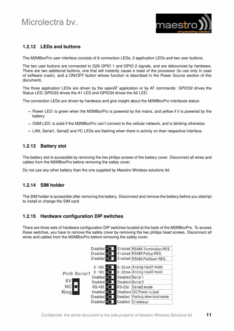
1.2.15 Hardware configuration DIP switches
There are three sets of hardware configuration DIP switches located at the back of the M2MBoxPro. To accessthese switches, you have to remove the safety cover by removing the two philips head screws. Disconnect allwires and cables from the M2MBoxPro before removing the safety cover.
Confidential, the whole document is the sole property of Maestro Wireless Solutions ltd. 11
Microlectra bv.
The DIP switches usage is as follows:
– Pin 9 Serial 1: sets the signal connected to pin 9 of the serial 1 interface. 6V is a 6V 380mA voltageoutput that can be used to power external devices. NC makes the pin 9 floating, and ring connects thepin 9 to RS232 RI signal (standard modem port pinout)
– RS485 termination res. : enables or disables a 120ohm shunt resistor between the two wires of theSerial2 RS interface.
– RS485 pull-up res.: enables or disables a 560ohm resistor to pull-up RS485+ signal to 5V. This 5Vvoltage is isolated from the other interfaces of the M2MBoxPro. It is defined by reference to the pull-down voltage.
– RS485 pulldown res.: enables or disables a 560ohm resistor to pull-down RS485- signal to 0V. This 0Vvoltage is isolated from the other interfaces of the M2MBoxPro. It is defined by reference to the pull-upvoltage.
– Analog input1 mode: enables or disables a 500ohm shunt resistor across the pins of the AI0 input(0-20mA mode). When this resistor is disabled, AI0 input impedance is 50.2kohm (0-10V mode)
– Analog input2 mode: enables or disables a 500ohm shunt resistor across the pins of the AI1 input(0-20mA mode). When this resistor is disabled, AI0 input impedance is 50.2kohm (0-10V mode)
– Serial1: enables or disables the serial port driver of serial1 interface, for power saving
– Serial2: enables or disables the serial port driver of serial2 interface, for power saving
– Serial2 mode: sets the serial2 interface to operate either in RS232, either in RS485 mode.
– I2C power output: enable or disable the 2.8V power output on the I²C interface connector, for powersaving.
– DI wake-up: enable or disable the modem start-up circuit connected to DI0. When enabled, any risingedge on DI0 will cause the modem to switch on. When disabled, DI0 will not start the modem.
Confidential, the whole document is the sole property of Maestro Wireless Solutions ltd. 12
Microlectra bv.
Microlectra bv.Hermanus Boerhaavestraat 6. 3261 ME Oud-Beijerland. Netherlands.
Tel 31(0)186-616290 Fax 31(0)186-610349 www.microlectra.nl [email protected]
Chapter 2
Installation
2.1 Inserting SIM card and battery
Use a small Philips head screwdriver to remove the two screws of the battery cover. The gently slide the coverout.
Under the cover you will see the battery and the hardware configuration DIP switches.
Take the battery out of its slot to reveal the SIM card holder. Slide and rotate the holder, insert the SIM cardand put the holder back in closed position. Make sure that the SIM card holder is correctly secured.
If you need to modify the hardware configuration through the DIP switches, now is the good time. ConsultMaestro or your distributor if you are not sure about the correct position of the switches.
Now put back the battery into its slot, and connect the battery connector to the socket on the M2MBoxPromotherboard. The socket is foolproof so you can not connect the battery wrongly.
When shipping from Maestro, the battery will always be disconnected. Do not forget to connect the batterybefore using the M2MBoxPro.
2.2 Mounting the M2MBoxPro
The M2MBoxPro is designed to be mounted on 35mm DIN rail.
First align the bottom part of the mount groove of the M2MBoxPro against the bottom side of the DIN rail, thenpush the device against the rail until you hear a click sound. The M2MBoxPro is now secured on the DIN rail.
To remove the M2MBoxPro from the DIN rail, use a flat head screwdriver to lift the top blue DIN clip of thedevice, then take out the device. In case the blue DIN clip falls off the M2MBoxPro, put it back in its slot.
2.3 Connect the external antenna (SMA type)
Connect this to an external antenna with SMA male connector. If you are using a different antenna than theone provided, make sure it is for the GSM frequency with impedance of 50ohm, and also connector is securedtightly.
Confidential, the whole document is the sole property of Maestro Wireless Solutions ltd. 13
Microlectra bv.
Note: Please use antenna designed for GSM device operation. Incorrect antenna will affect communicationand even damage the modem.
2.4 Connect the modem to external device
You can use the provided RS232 serial cable to connect the M2MBoxPro Serial1 interface to an externalcontroller or computer.
2.5 Connect the DC power supply
Connect the two tips of the provided power cord to a DC supply. Refer to the following for power supplyrequirement.
Input voltage range 9V – 28VRated current 850mA
Insert the two tips into the “Power” terminal block of the M2MBoxPro, screw the connector to secure the wiresthen connect it to the M2MBoxPro. The modem will turn on automatically (if not already on).
The GPRS status indicator on the modem will be lit when power on. After a few seconds it will go flashingslowly (registered on cellular network).
Confidential, the whole document is the sole property of Maestro Wireless Solutions ltd. 14
Microlectra bv.
Microlectra bv.Hermanus Boerhaavestraat 6. 3261 ME Oud-Beijerland. Netherlands.
Tel 31(0)186-616290 Fax 31(0)186-610349 www.microlectra.nl [email protected]
Chapter 3
Hardware block diagram
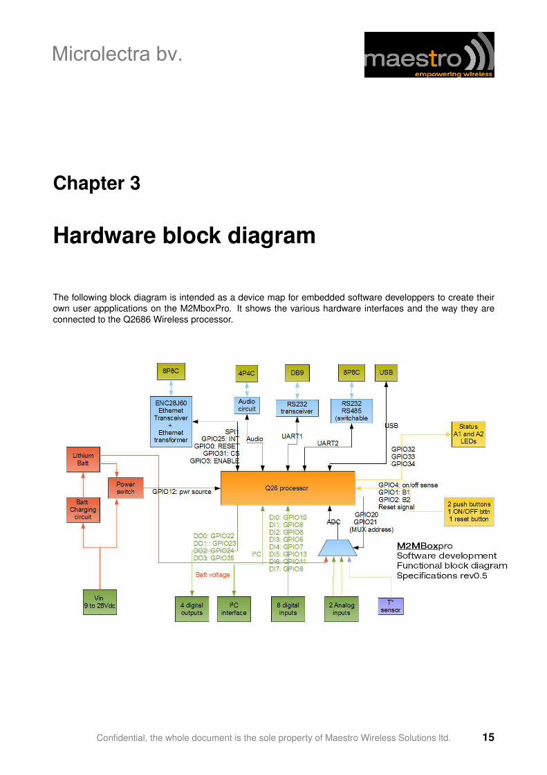
The following block diagram is intended as a device map for embedded software developpers to create theirown user appplications on the M2MboxPro. It shows the various hardware interfaces and the way they areconnected to the Q2686 Wireless processor.
Confidential, the whole document is the sole property of Maestro Wireless Solutions ltd. 15
Microlectra bv.