giovenzana - international bv
TRANSCRIPT
GIOVENZANAINTERNATIONAL B.V.
LIFTING EQUIPMENT CATALOGUE
T E C H N O - L I F T I N G E Q U I P M E N T

!"#$%&'%'(!%)$*%')!"%'+(,-.-,/-.(01-(,2310(04(5462789(2:(4,6-,(04(25;,4/-(01-2,(;-,74,5<:=-9
<>>(0-=1:2=<>(<:6(7?:=024:<>(=1<,<=0-,2.02=.(47(01-(;,46?=0.(.14@:(2:(01-(=<0<>43?-(@2014?0(;,24,(:402=-
<.(012.(2:74,5<024:(2.(2:0-:6-6(74,(3-:-,<>(A:4@>-63-(<:6(2.(:40(>-3<>>8(B2:62:3C
Editio
n 2
010
- G
raphic
desig
n:
GasG
as s
as g
asgas@
gasgas.it
ww
w.g
asgas.it
- Pre
ss a
nd o
ffset:
Tip
ogra
fia M
TM
sas V
ia N
ullo
, 50 - 2
4033 C
alu
sco d
'Adda (
BG
) Italy
The Company
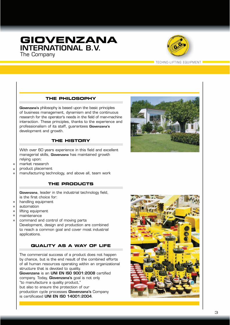
24/-:D<:<E. philosophy is based upon the basic principles
of business management, dynamism and the continuous
research for the operator’s needs in the field of man-machine
interaction. These principles, thanks to the experience and
professionalism of its staff, guarantees 24/-:D<:<E.
development and growth.
THE PHILOSOPHY
The commercial success of a product does not happen
by chance, but is the end result of the combined efforts
of all human resources operating within an organizational
structure that is devoted to quality.
Giovenzana is an UNI EN ISO 9001:2008 certified
company. Today, Giovenzana’s goal is not only
“to manufacture a quality product,”
but also to ensure the protection of our
production cycle processes Giovenzana’s Company
is certificated UNI EN ISO 14001:2004.
QUALITY AS A WAY OF LIFE
With over 60 years experience in this field and excellent
managerial skills, 24/-:D<:< has maintained growth
relying upon:
market research
product placement
manufacturing technology, and above all, team work
THE HISTORY
24/-:D<:<, leader in the industrial technology field,
is the first choice for:
handling equipment
automation
lifting equipment
maintenance
command and control of moving parts
Development, design and production are combined
to reach a common goal and cover most industrial
applications.
THE PRODUCTS
GIOVENZANAINTERNATIONAL B.V.
3
TECHNO-LIFT ING EQUIPMENT
The Company
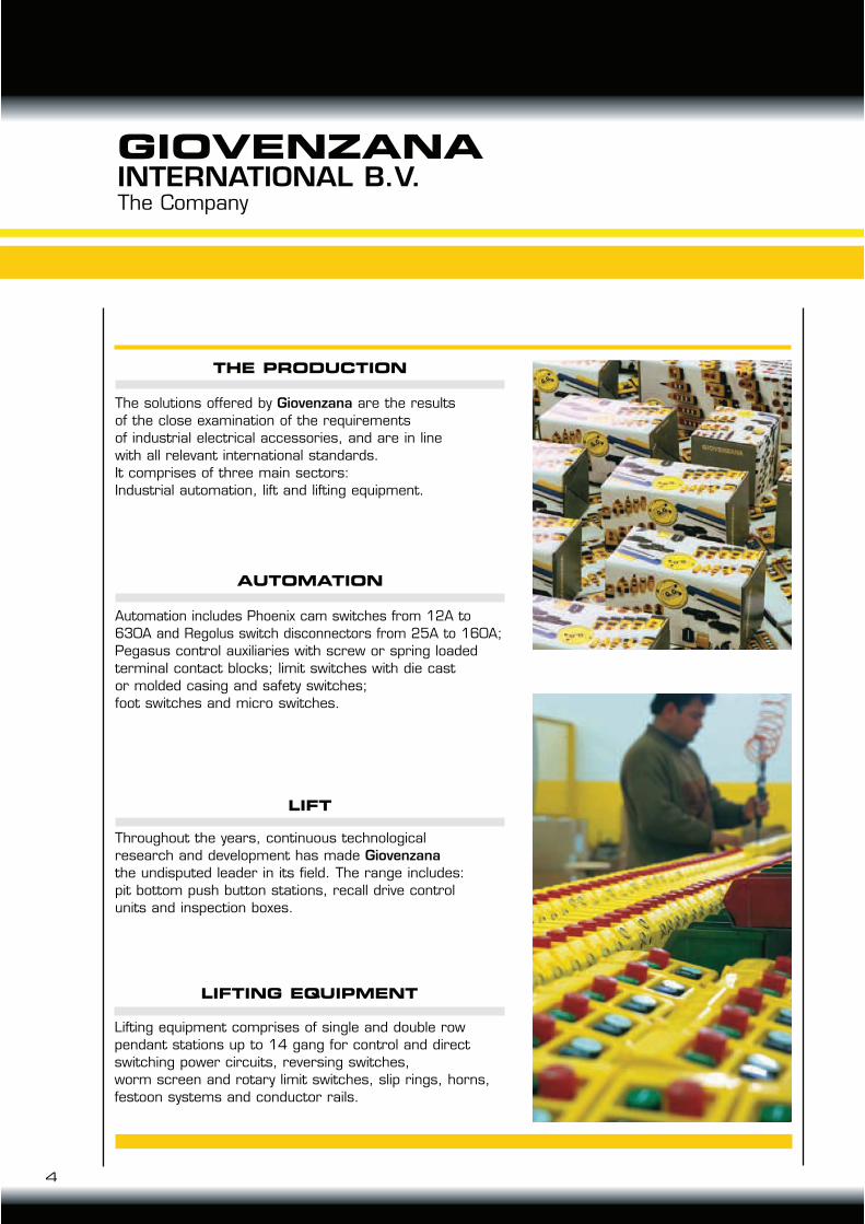
The solutions offered by Giovenzana are the results
of the close examination of the requirements
of industrial electrical accessories, and are in line
with all relevant international standards.
It comprises of three main sectors:
Industrial automation, lift and lifting equipment.
THE PRODUCTION
Automation includes Phoenix cam switches from 12A to
630A and Regolus switch disconnectors from 25A to 160A;
Pegasus control auxiliaries with screw or spring loaded
terminal contact blocks; limit switches with die cast
or molded casing and safety switches;
foot switches and micro switches.
AUTOMATION
Throughout the years, continuous technological
research and development has made Giovenzana
the undisputed leader in its field. The range includes:
pit bottom push button stations, recall drive control
units and inspection boxes.
LIFT
Lifting equipment comprises of single and double row
pendant stations up to 14 gang for control and direct
switching power circuits, reversing switches,
worm screen and rotary limit switches, slip rings, horns,
festoon systems and conductor rails.
LIFTING EQUIPMENT
4
GIOVENZANAINTERNATIONAL B.V.
Certifications
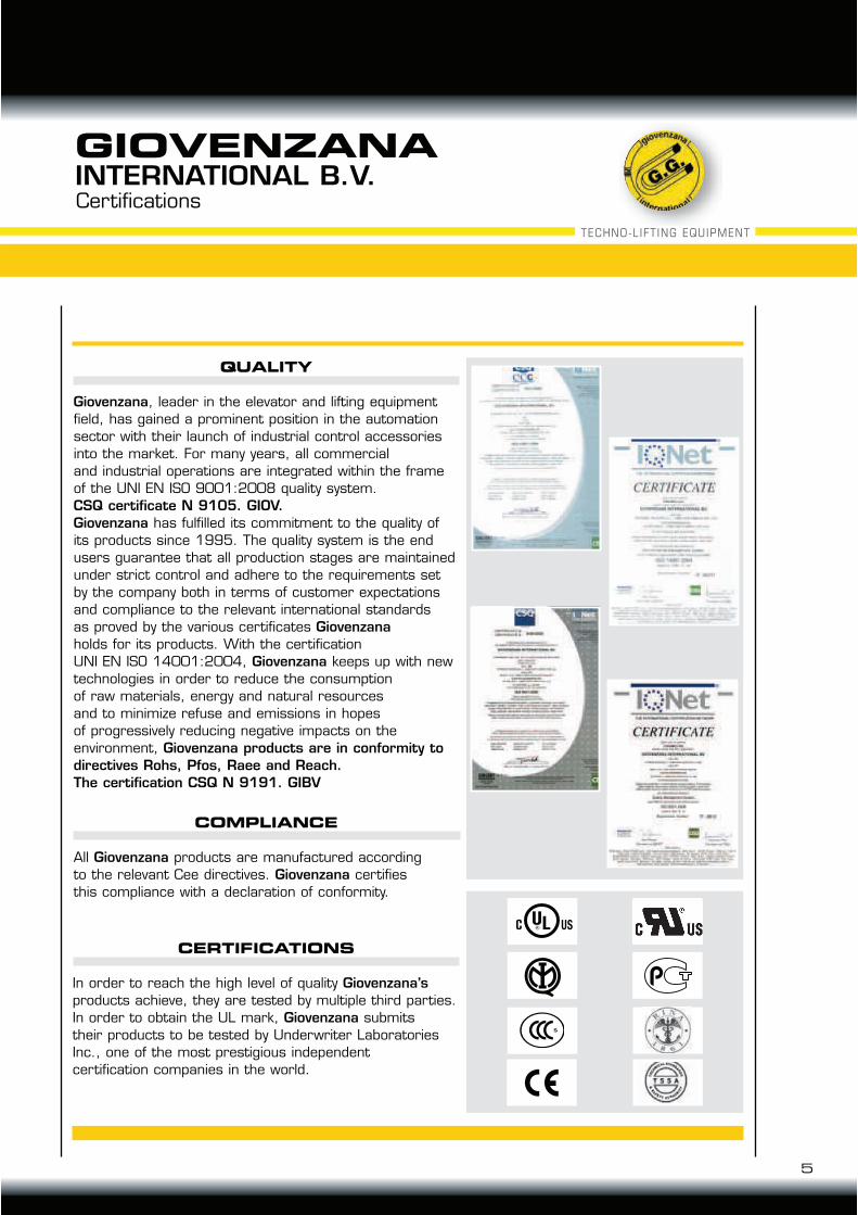
CERTIFICATIONS
In order to reach the high level of quality Giovenzana’s
products achieve, they are tested by multiple third parties.
In order to obtain the UL mark, Giovenzana submits
their products to be tested by Underwriter Laboratories
Inc., one of the most prestigious independent
certification companies in the world.
Giovenzana, leader in the elevator and lifting equipment
field, has gained a prominent position in the automation
sector with their launch of industrial control accessories
into the market. For many years, all commercial
and industrial operations are integrated within the frame
of the UNI EN ISO 9001:2008 quality system.
CSQ certificate N 9105. GIOV.
Giovenzana has fulfilled its commitment to the quality of
its products since 1995. The quality system is the end
users guarantee that all production stages are maintained
under strict control and adhere to the requirements set
by the company both in terms of customer expectations
and compliance to the relevant international standards
as proved by the various certificates Giovenzana
holds for its products. With the certification
UNI EN ISO 14001:2004, Giovenzana keeps up with new
technologies in order to reduce the consumption
of raw materials, energy and natural resources
and to minimize refuse and emissions in hopes
of progressively reducing negative impacts on the
environment, Giovenzana products are in conformity to
directives Rohs, Pfos, Raee and Reach.
The certification CSQ N 9191. GIBV
QUALITY
COMPLIANCE
All Giovenzana products are manufactured according
to the relevant Cee directives. Giovenzana certifies
this compliance with a declaration of conformity.
GIOVENZANAINTERNATIONAL B.V.
5
TECHNO-LIFT ING EQUIPMENT
Certifications
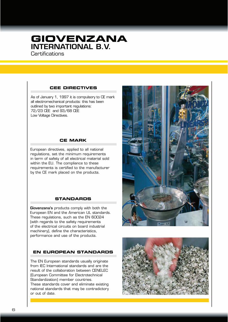
CE MARK
European directives, applied to all national
regulations, set the minimum requirements
in term of safety of all electrical material sold
within the EU. The compliance to these
requirements is certified to the manufacturer
by the CE mark placed on the products.
STANDARDS
Giovenzana’s products comply with both the
European EN and the American UL standards.
These regulations, such as the EN 60024
(with regards to the safety requirements
of the electrical circuits on board industrial
machinery), define the characteristics,
performance and use of the products.
EN EUROPEAN STANDARDS
The EN European standards usually originate
from IEC International standards and are the
result of the collaboration between CENELEC
(European Committee for Electrotechnical
Standardization) member countries.
These standards cover and eliminate existing
national standards that may be contradictory
or out of date.
CEE DIRECTIVES
As of January 1, 1997 it is compulsory to CE mark
all electromechanical products: this has been
outlined by two important regulations:
72/23 CEE and 93/68 CEE
Low Voltage Directives.
6
GIOVENZANAINTERNATIONAL B.V.
7
TECHNO-LIFT ING EQUIPMENT
Table of contents
GIOVENZANAINTERNATIONAL B.V.
pag. 11
pag. 33
pag. 39
pag. 45
pag. 74
pag. 76
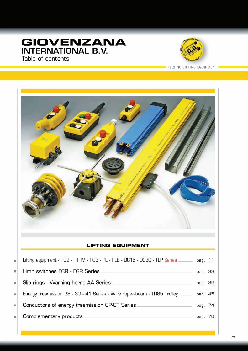
Lifting equipment - P02 - PTRM - P03 - PL - PLB - DC16 - DC30 - TLP Series
Limit switches FCR - FGR Series
Slip rings - Warning horns AA Series
Energy trasmission 28 - 30 - 41 Series - Wire rope-i-beam - TR85 Trolley
Conductors of energy trasmission CP-CT Series
Complementary products
LIFTING EQUIPMENT

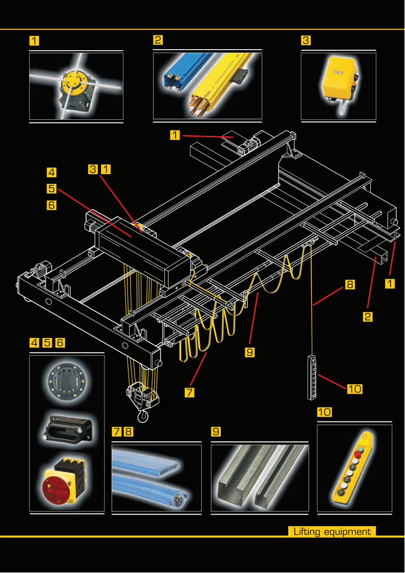
Lifting equipment
5
4
6
3
7
9
8
10
2
1
1
1
7 8 9
1 3
10
4 5 6
2

General characteristics
P02 - PTRM Series pendant stationsfor small hoist applications
P03 Series pendant stationsfor small hoist applications
Single row PL Series pendant stationsfor control circuits
Double row PLB Series pendant stations for control circuits
PL - PLB Series - Pendant stationsfor control circuits - Enclosures pendant stations single products and Accessories
PL - PLB Series pendant stations forcontrol circuits, Configuration and Symbols
PL - PLB Series pendant stationsfor control circuits, Assembly
DC16 Series pendant stationsfor small hoist applications
DC30 Series pendant stationsfor direct switching power circuits
Pendant stations for control circuitsand power circuits - Schemes
TLP light Series - Pendant stations
General and electricals characteristics
11
Table of contents
TECHNO-LIFT ING EQUIPMENT
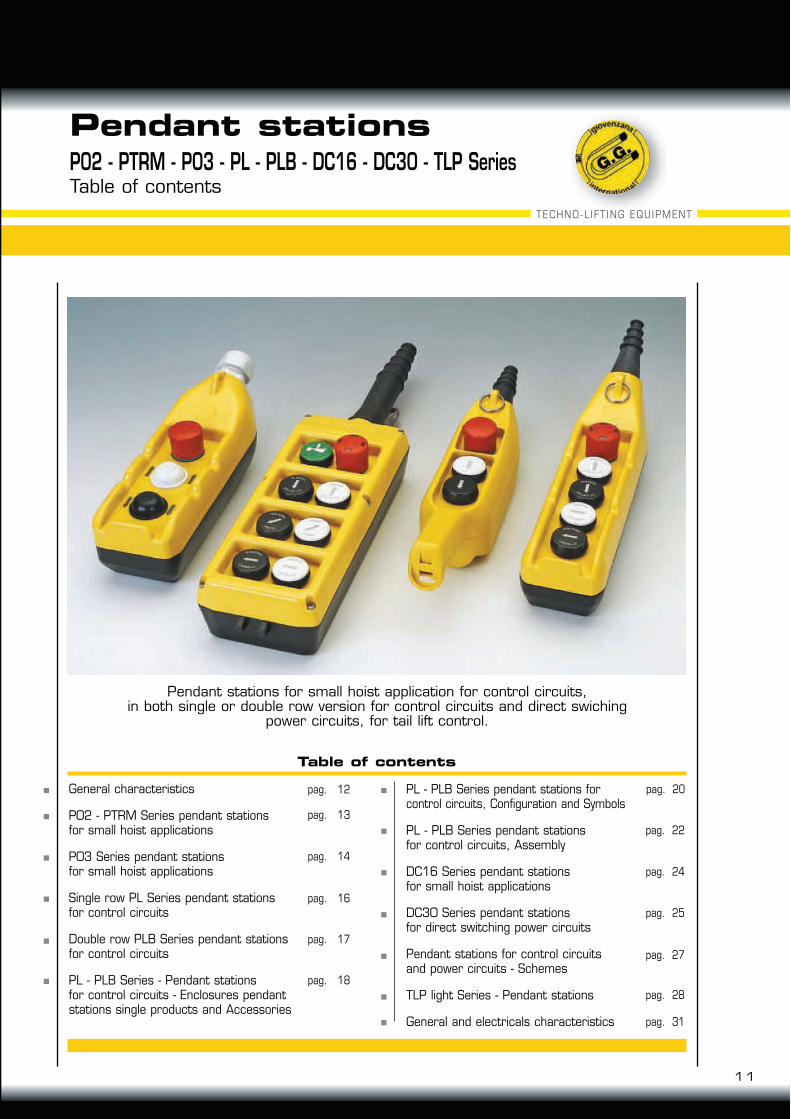
Pendant stations for small hoist application for control circuits,in both single or double row version for control circuits and direct swiching
power circuits, for tail lift control.
Pendant stations
Table of contents
pag. 12
pag. 13
pag. 14
pag. 16
pag. 17
pag. 18
pag. 20
pag. 22
pag. 24
pag. 25
pag. 27
pag. 28
pag. 31
P02 - PTRM - P03 - PL - PLB - DC16 - DC30 - TLP Series

P02 - PTRM - P03 - PL - PLB - DC16 - DC30 - TLP SeriesCharacteristics
12
Pendant stations
Small hoist application
For auxiliaries circuits
Direct command
Bower circuit
Push button station for tail lifts
GENERAL CHARACTERISTICS
Giovenzana International Company, leader in lifting equipment control, made a wide rangeof standard products for all installation requirements with actual specification and safety guidelines.
The Lift Equipments products serie are classified as: Giovenzana International Company, made a wide range of standard products for all installation requirements with actual specification and safety guidelines.
The Lift Equipment products serie are classified as: IEC 947-5-1, EN60947-5-1, UL508 and job:IEC 204-1, EN60204-1, EN ISO 13850 comply with achieved according to the needs and requirements
operator are classified in 5 Product Family:
All operators are colored or symbology in laser engraving comply with EN60204-1 e FEM 9.941
CERTIFICATIONS:
The pendant stations P02, P03, PL e PLB Series are Certificated cuL.
20
8 -
8.1
8"
26
8 -
10
.55
"
2.28" 80 - 3.15"
2.36"
60
58
Ø 11
Ø 9
Ø7
Ø 14
Pendant stations
TECHNO-LIFT ING EQUIPMENT
13
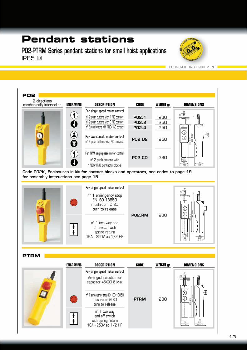
n° 1 emergency stop EN ISO 13850mushroom Ø 30turn to release
230
For single speed motor control
Arranged execution for capacitor 45X90 Ø Max
n° 1 two wayand off switch
with spring return16A - 250V ac 1/2 HP
PTRM
230
250
250
250
230
For single speed motor control
For two-speeds motor control
20
8 -
8.1
8"
26
8 -
10
.55
"
2.28" 2.36"
6058
1.37"
35
1.3
7"
35
Ø 11
Ø 9
Ø7
Ø 14
20
8 -
8.1
8"
26
8 -
10
.55
"
2.28" 80 - 3.15"
2.36"
60
58
1.37"
35
Ø 11
Ø 9
Ø7
Ø 14
PO2
CODE WEIGHT gr
n° 2 push buttons with 1 NO contact
n° 2 push buttons with 2 NO contact
n° 2 push buttons with 1NC+1NO contact
DESCRIPTIONENGRAVING DIMENSIONS2 directions
mechanically interlocked
n° 2 push buttons with NO contacts
n° 2 push-buttons with
1NC+1NO contacts blocks
For 1kW single-phase motor control
P02.1
P02.2
P02.4
P02.D2
P02.CD
PTRM
CODE WEIGHT grENGRAVING DESCRIPTION DIMENSIONS
230
For single speed motor control
n° 1 emergency stopEN ISO 13850
mushroom Ø 30turn to release
n° 1 two way andoff switch withspring return
16A - 250V ac 1/2 HP
P02.RM
P02-PTRM Series pendant stations for small hoist applicationsIP65
Code P02K, Enclosures in kit for contact blocks and operators, see codes to page 19
for assembly instructions see page 15
Pendant stations
14
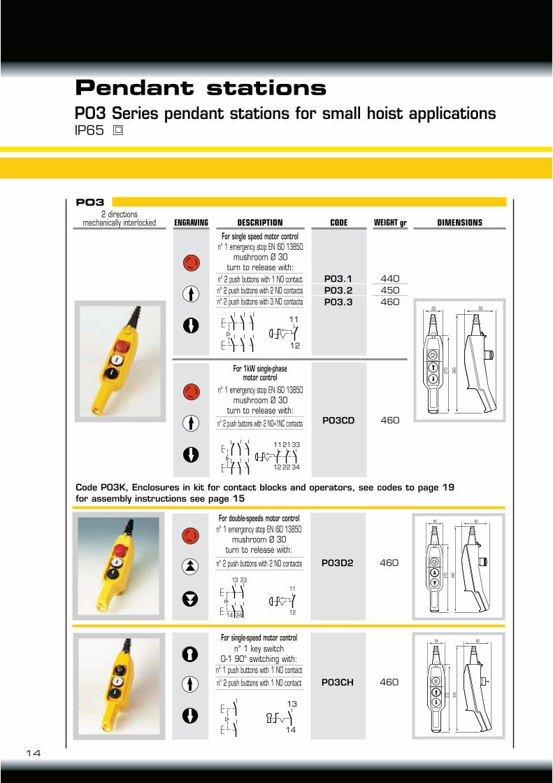
P03 Series pendant stations for small hoist applicationsIP65
P03.1
P03.2
P03.3
n° 2 push buttons with 1 NO contact
n° 2 push buttons with 2 NO contacts
n° 2 push buttons with 3 NO contacts
n° 2 push buttons with 2 NO+1NC contacts
440
450
460
PO3CD 460
For single speed motor control
9065
27
0
34
0
PO3
CODE WEIGHT grENGRAVING DESCRIPTION DIMENSIONS
n° 1 emergency stop EN ISO 13850mushroom Ø 30
turn to release with:
n° 1 emergency stop EN ISO 13850mushroom Ø 30
turn to release with:
11
12
P03D2n° 2 push buttons with 2 NO contacts 460
For double-speeds motor control
n° 1 emergency stop EN ISO 13850mushroom Ø 30
turn to release with:
11
12
13 23
14 24
P03CHn° 2 push buttons with 1 NO contact 460
For single-speed motor control
n° 1 key switch0-1 90° switching with:
n° 1 push buttons with 1 NO contact
13
14
11
12
21
22
33
34
For 1kW single-phasemotor control
9065
27
0
34
0
9065
27
0
34
0
2 directionsmechanically interlocked
Code P03K, Enclosures in kit for contact blocks and operators, see codes to page 19
for assembly instructions see page 15
15
TECHNO-LIFT ING EQUIPMENT
Pendant stations
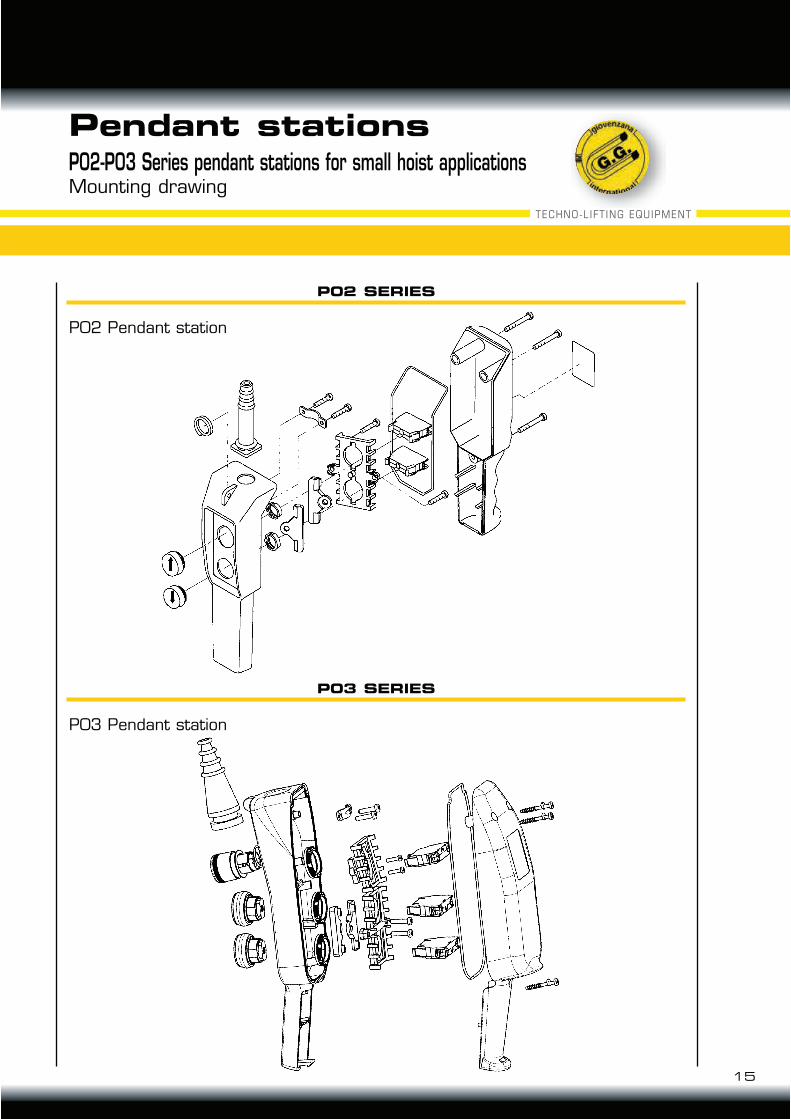
P02-P03 Series pendant stations for small hoist applicationsMounting drawing
P02 SERIES
P03 SERIES
P02 Pendant station
P03 Pendant station
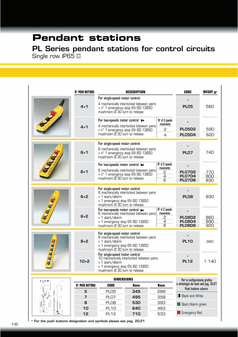
Single row IP65PL Series pendant stations for control circuits
Pendant stations
16
8+2
10+2
5
7
8
10
12
345
495
530
640
710
PL05
PL07
PL08
PL10
PL12
288
358
393
463
533
CODE WEIGHT grN° PUSH BUTTONS
4+1
4+1
DESCRIPTION
Per la configurazione graficae simbologia dei tasti vedi pag. 20-21
560PL05
6+1
6+1
For single-speed motor control
4 mechanically interlocked between pairs+ n° 1 emergency stop EN ISO 13850mushroom Ø 30 turn to release
For two-speeds motor control
4 mechanically interlocked between pairs + n° 1 emergency stop EN ISO 13850mushroom Ø 30 turn to release
6+2
6+2
PL10
PL12
990
1.140
740
For single-speed motor control
For two-speeds motor control
6 mechanically interlocked between pairs + n° 1 emergency stop EN ISO 13850mushroom Ø 30 turn to release
6 mechanically interlocked between pairs+ n° 1 emergency stop EN ISO 13850mushroom Ø 30 turn to release
246
N° of 2 speedsmovements
246
N° of 2 speedsmovements
860890920
770800830
830PL08
PL08D2PL08D4PL08D6
For single-speed motor control
For two-speeds motor control6 mechanically interlocked between pairs + 1 start/allarm+ 1 emergency stop EN ISO 13850mushroom Ø 30 turn to release
6 mechanically interlocked between pairs + 1 start/allarm+ 1 emergency stop EN ISO 13850mushroom Ø 30 turn to release
For single-speed motor control
For single-speed motor control10 mechanically interlocked between pairs + 1 start/allarm+ 1 emergency stop EN ISO 13850mushroom Ø 30 turn to release
8 mechanically interlocked between pairs + 1 start/allarm+ 1 emergency stop EN ISO 13850mushroom Ø 30 turn to release
PL07
PL07D2PL07D4PL07D6
DIMENSIONS
N° PUSH BUTTONS CODE Amm BmmPush buttons colours:
Black and White
Start/Alarm green
Emergency Red
590
620
2
4
N° of 2 speedsmovements
PL05D2
PL05D4
For the push buttons designation and symbols please see pag. 20-21
17
TECHNO-LIFT ING EQUIPMENT
8+2
10+2
12+2
8
10
12
468
101214
345399453547601655
PLB04PLB06PLB08PLB10PLB12PLB14
185239293347401455
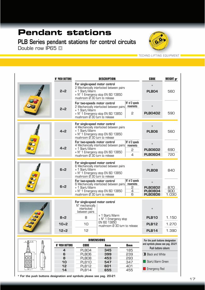
Pendant stationsPLB Series pendant stations for control circuitsDouble row IP65
560
CODE WEIGHT grN° PUSH BUTTONS
PLB06
2+2
2+2
For single-speed motor control
DESCRIPTION
For two-speeds motor control4 Mechanically interlocked between pairs+ 1 Start/Allarm+ N° 1 Emergency stop EN ISO 13850mushroom Ø 30 turn to release
A
B
108 65
Ø 8---24For the push buttons designation
and symbols please see pag. 20-21
N° of 2 speedsmovements
560PLB04
5902 PLB04D2
4+2
4+2
For single-speed motor control2 Mechanically interlocked between pairs+ 1 Start/Allarm+ N° 1 Emergency stop EN ISO 13850mushroom Ø 30 turn to release
For two-speeds motor control2 Mechanically interlocked between pairs+ 1 Start/Allarm+ N° 1 Emergency stop EN ISO 13850mushroom Ø 30 turn to release
6+2
6+2
PLB10
PLB12
PLB14
1.150
1.270
1.390
For single-speed motor controlN° mechanically
interlockedbetween pairs
+ 1 Start/Allarm+ N° 1 Emergency stopEN ISO 13850mushroom Ø 30 turn to release
690
720
2
4
N° of 2 speedsmovements
PLB06D2
PLB06D4
4 Mechanically interlocked between pairs+ 1 Start/Allarm+ N° 1 Emergency stop EN ISO 13850mushroom Ø 30 turn to release
870900
1.030
246
N° of 2 speedsmovements
840PLB08
PLB08D2PLB08D4PLB08D6
For single-speed motor control
For two-speeds motor control6 Mechanically interlocked between pairs+ 1 Start/Allarm+ N° 1 Emergency stop EN ISO 13850mushroom Ø 30 turn to release
6 Mechanically interlocked between pairs+ 1 Start/Allarm+ N° 1 Emergency stop EN ISO 13850mushroom Ø 30 turn to release
DIMENSIONS
N° PUSH BUTTONS CODE Amm BmmPush buttons colours:
Black and White
Start/Alarm Green
Emergency Red
For the push buttons designation and symbols please see pag. 20-21
18
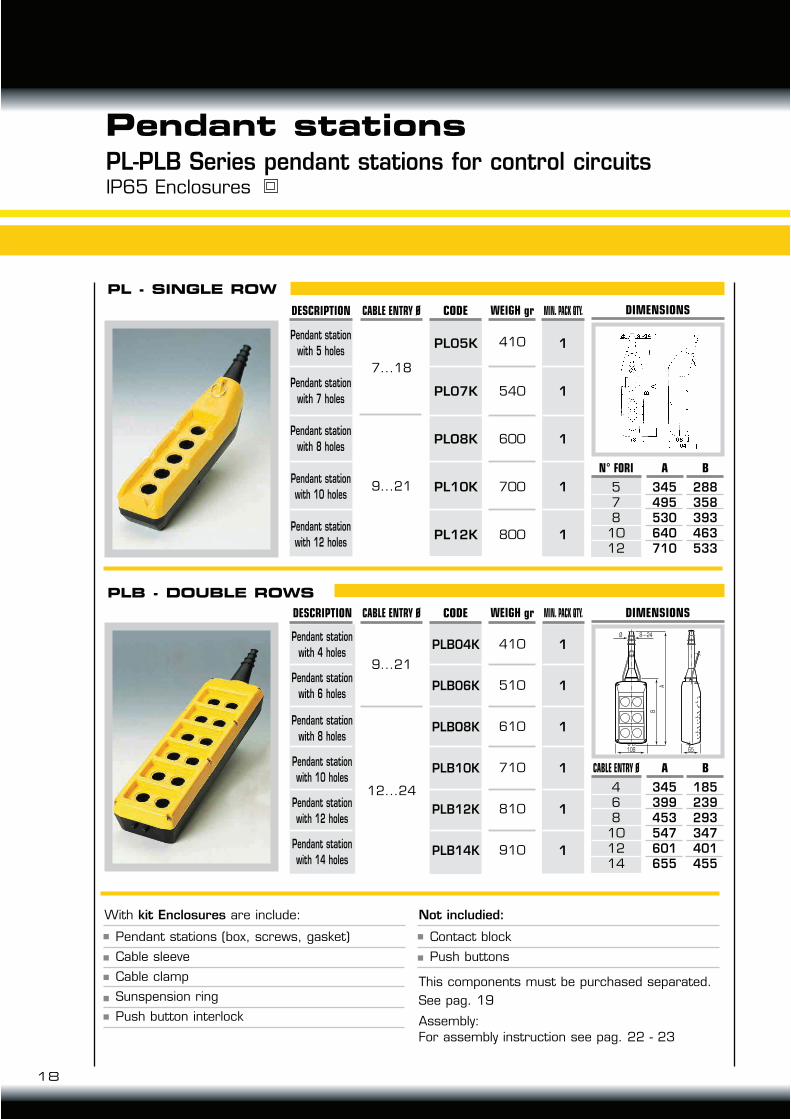
Pendant stationsPL-PLB Series pendant stations for control circuitsIP65 Enclosures
PL - SINGLE ROW
WEIGH grDESCRIPTION
Pendant station with 5 holes
Pendant station with 7 holes
Pendant station with 8 holes
Pendant station with 10 holes
Pendant station with 12 holes
410
540
600
700
800
CABLE ENTRY Ø
7...18
9...21
MIN. PACK QTY.
1
1
1
1
1
CODE
PL05K
PL07K
PLO8K
PL10K
PL12K
PLB - DOUBLE ROWS
Pendant station with 4 holes
Pendant station with 6 holes
Pendant station with 8 holes
Pendant station with 10 holes
Pendant station with 12 holes
Pendant station with 14 holes
410
510
610
710
810
910
WEIGH grDESCRIPTION
9...21
12...24
CABLE ENTRY Ø
PLB04K
PLB06K
PLBO8K
PLB10K
PLB12K
PLB14K
CODE
1
1
1
1
1
1
MIN. PACK QTY.
DIMENSIONS
578
1012
N° FORI
345495530640710
A
288358393463533
B
A
B
108 65
Ø 8---24
DIMENSIONS
468
101214
CABLE ENTRY Ø
345399453547601655
A
185239293347401455
B
With kit Enclosures are include:
Assembly:
For assembly instruction see pag. 22 - 23
Not includied:
This components must be purchased separated.
See pag. 19
Pendant stations (box, screws, gasket)
Cable sleeve
Cable clamp
Sunspension ring
Push button interlock
Contact block
Push buttons
19
TECHNO-LIFT ING EQUIPMENT
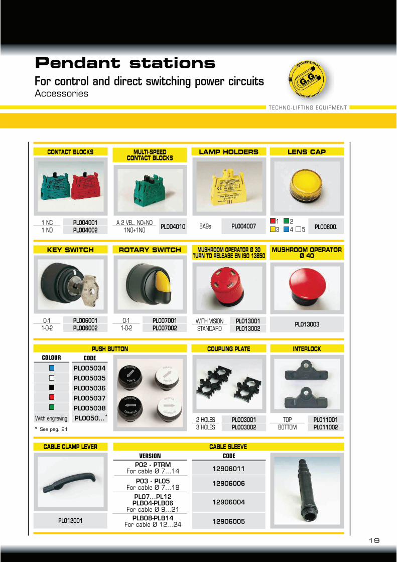
P02 - PTRMFor cable Ø 7...14
P03 - PL05For cable Ø 7...18
PL07...PL12PLB04-PLB06
For cable Ø 9...21
PLB08-PLB14For cable Ø 12...24
Pendant stationsFor control and direct switching power circuitsAccessories
CONTACT BLOCKS
1 NC1 NO
PLOO4001PLOO4002
LAMP HOLDERS
BA9s PLOO4007
LENS CAP
1
3
2
4 5 PLOO800.
MULTI-SPEEDCONTACT BLOCKS
PLOO4010 A 2 VEL. NO+NO
1NO+1NO
KEY SWITCH
0-11-0-2
PLOO6001PLOO6002
ROTARY SWITCH
0-11-0-2
PLOO7001PLOO7002
PUSH BUTTON COUPLING PLATE INTERLOCK
CABLE CLAMP LEVER CABLE SLEEVE
PLO12001
MUSHROOM OPERATOR Ø 30TURN TO RELEASE EN ISO 13850
WITH VISIONSTANDARD
PLO13001PLO13002
2 HOLES3 HOLES
PLOO3001PLOO3002
TOPBOTTOM
PLO11001PLO11002
MUSHROOM OPERATORØ 40
PLO13003
PLOO5034
PLOO5035
PLOO5036
PLOO5037
PLOO5038
PLOO50...
CODECOLOUR
*
* See pag. 21
With engraving
12906011
12906006
12906004
12906005
CODEVERSION
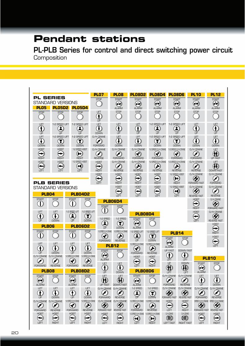
PL05 PL05D2 PL05D4
PL07 PL08 PL08D2 PL08D4 PL08D6 PL10 PL12
STOP
UP
LIFT
DOWN
LIFT
STOP
UP
1-2 SPEED LIFT
DOWN
1-2 SPEED LIFT
STOP
UP
1-2 SPEED LIFT
DOWN
1-2 SPEED LIFT
STOP
UP
LIFT
DOWN
LIFT
FORWARD
O/H CRANE
REVERSE
O/H CRANE
LEFT
HOIST
RIGHT
HOIST
START
STOP
ALARM
DOWN
LIFT
FORWARD
O/H CRANE
REVERSE
O/H CRANE
LEFT
HOIST
RIGHT
HOIST
UP
LIFT
STOP
ALARM
DOWN
LIFT
UP
LIFT
FORWARD
O/H CRANE
REVERSE
O/H CRANE
LEFT
HOIST
RIGHT
HOIST
START
STOP
ALARM
DOWN
1-2 SPEED LIFT
UP
1-2 SPEED LIFT
FORWARD
1-2 SPEED O/H CRANE
REVERSE
1-2 SPEED O/H CRANE
LEFT
HOIST
RIGHT
HOIST
START
STOP
ALARM
DOWN
1-2 SPEED LIFT
UP
1-2 SPEED LIFT
FORWARD
1-2 SPEED O/H CRANE
REVERSE
1-2 SPEED O/H CRANE
LEFT
1-2 SPEED HOIST
RIGHT
1-2 SPEED HOIST
START
STOP
ALARM
DOWN
LIFT
UP
LIFT
FORWARD
O/H CRANE
REVERSE
O/H CRANE
FORWARD FAST
O/H CRANE
O/H CRANE
LEFT
HOIST
RIGHT
HOIST
LEFT
HOIST
RIGHT
HOIST
START
STOP
ALARM
DOWN
LIFT
UP
LIFT
UP FAST
LIFT
DOWN FAST
LIFT
FORWARD
O/H CRANE
REVERSE
O/H CRANE
FORWARD FAST
O/H CRANE
REVERSE FAST
REVERSE FAST
O/H CRANE
START
PLB08
START STOP
UP
LIFT
DOWN
LIFT
FORWARD
O/H CRANE
REVERSE
O/H CRANE
LEFT
HOIST
RIGHT
HOIST
PLB08D2
START STOP
UP
LIFT
DOWN
LIFT
LEFT
HOIST
RIGHT
HOIST
PLB06
START STOP
UP
LIFT
DOWN
LIFT
FORWARD
O/H CRANE
REVERSE
O/H CRANE
PLB04
START STOP
UP DOWN
PLB04D2
START STOP
UP DOWN
LIFT LIFT 1-2 SPEED LIFT 1-2 SPEED LIFT
PLB06D2
START STOP
UP
LIFT
DOWN
LIFT
FORWARD
1-2 SPEED O/H CRANE
REVERSE
1-2 SPEED O/H CRANE
PLB06D4
START STOP
UP
1-2 SPEED
DOWN
1-2 SPEED
FORWARD
1-2 SPEED O/H CRANE
REVERSE
1-2 SPEED O/H CRANE
PLB08D6
START
ALARM
STOP
UP
1-2 SPEED
DOWN
1-2 SPEED
FORWARD
1-2 SPEED O/H CRANE
REVERSE
1-2 SPEED O/H CRANE
LEFT
1-2 SPEED O/H CRANE
RIGHT
1-2 SPEED O/H CRANE
PLB08D4
START
ALARM
STOP
UP
1-2 SPEED LIFT
DOWN
1-2 SPEED LIFT
FORWARD
1-2 SPEED O/H CRANE
REVERSE
1-2 SPEED O/H CRANE
LEFT
HOIST
RIGHT
HOIST
PLB14
START
ALARM
STOP
UP FAST
LIFT
DOWN FAST
LIFT
UP
LIFT
DOWN
LIFT
FORWARD
O/H CRANE
REVERSE
O/H CRANE
FORWARD FAST
O/H CRANE O/H CRANE
REVERSE FAST
LEFT
HOIST
RIGHT
HOIST
LEFT FAST
O/H CRANE O/H CRANE
RIGHT FAST
PLB12
START
ALARM
STOP
UP
LIFT
DOWN
LIFT
UP FAST
LIFT
DOWN FAST
LIFT
FORWARD
O/H CRANE
REVERSE
O/H CRANE
FORWARD FAST
O/H CRANE O/H CRANE
REVERSE FAST
LEFT
HOIST
RIGHT
HOIST
PLB10
START
ALARM
STOP
UP
LIFT
DOWN
LIFT
FORWARD
O/H CRANE
REVERSE
O/H CRANE
FORWARD FAST
SPEED O/H CRANE SPEED O/H CRANE
REVERSE FAST
LEFT
HOIST
RIGHT
HOIST
FORWARD
1-2 SPEED O/H CRANE
REVERSE
1-2 SPEED O/H CRANE
RIGHT
HOIST
RIGHT
HOIST
LEFT
HOIST
LEFT
HOIST
RIGHT
1-2 SPEED HOIST
LEFT
1-2 SPEED HOIST
ALARM ALARM
PL SERIES
STANDARD VERSIONS
PLB SERIES
STANDARD VERSIONS
20
Pendant stationsPL-PLB Series for control and direct switching power circuitComposition
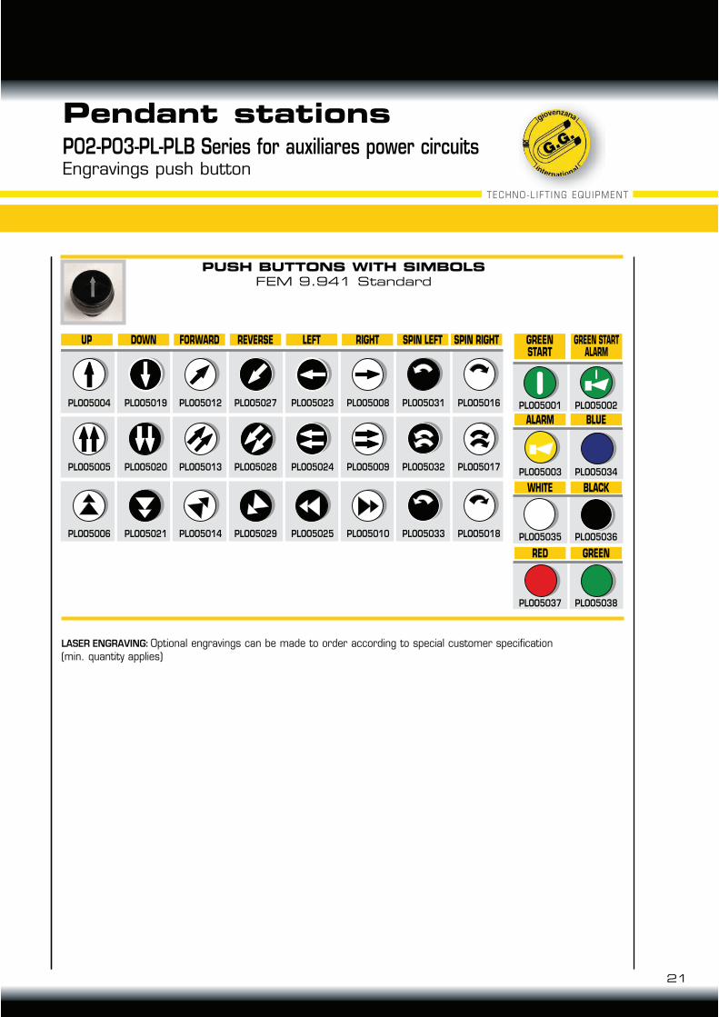
UP DOWN FORWARD REVERSE LEFT RIGHT SPIN LEFT SPIN RIGHT GREEN
START
GREEN START
ALARM
PLOO5004
PLOO5005
PLOO5006
PLOO5007
PLOO5019
PLOO5020
PLOO5021
PLOO5022
PLOO5012
PLOO5013
PLOO5014
PLOO5015
PLOO5027
PLOO5028
PLOO5029
PLOO5030
PLOO5023
PLOO5024
PLOO5025
PLOO5026
PLOO5008
PLOO5009
PLOO5010
PLOO5011
PLOO5031
PLOO5032
PLOO5033
PLOO5016
PLOO5017
PLOO5018
ALARM
WHITE
RED
BLUE
BLACK
GREEN
PLOO5001 PLOO5002
PLOO5003 PLOO5034
PLOO5035 PLOO5036
PLOO5037 PLOO5038
21
TECHNO-LIFT ING EQUIPMENT
Pendant stationsP02-P03-PL-PLB Series for auxiliares power circuitsEngravings push button
!"#$%#&'$!()&'*%Optional engravings can be made to order according to special customer specification(min. quantity applies)
PUSH BUTTONS WITH SIMBOLS
FEM 9.941 Standard
18
11
10
09 01
14 15
05 08
04
02
03
070617
13 12
16
22
QTY.N° REF. NO. DESCRICTION
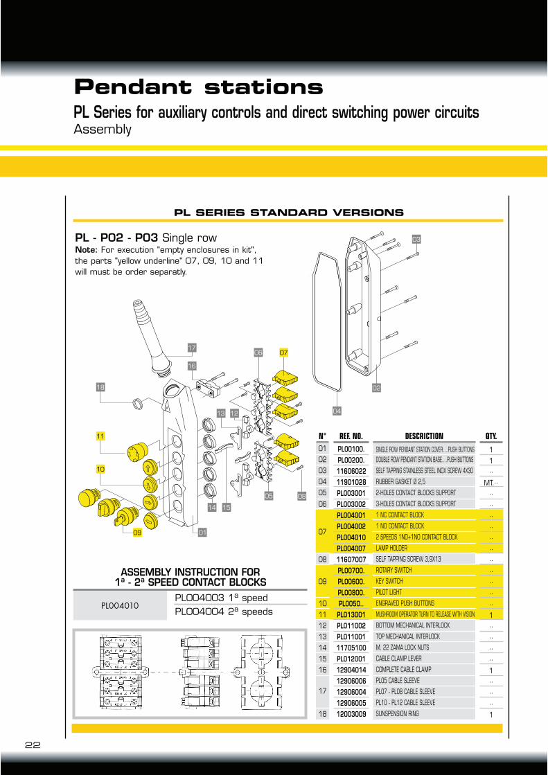
Pendant stationsPL Series for auxiliary controls and direct switching power circuitsAssembly
PL SERIES STANDARD VERSIONS
1
1
··
MT.··
··
··
··
··
··
··
··
··
··
··
··
1
··
··
··
··
1
··
··
··
1
ASSEMBLY INSTRUCTION FOR1a - 2a SPEED CONTACT BLOCKS
PL004010PL004003 1a speed
PL004004 2a speeds
PL - P02 - P03 Single rowNote: For execution "empty enclosures in kit",
the parts "yellow underline" 07, 09, 10 and 11
will must be order separatly.
PL00100.
PL00200.
11606022
11901028
PL003001
PL003002
PL004001
PL004002
PL004010
PL004007
11607007
PL00700.
PL00600.
PL00800.
PL0050..
PL013001
PL011002
PL011001
11705100
PL012001
12904014
12906006
12906004
12906005
12003009
01
02
03
04
05
06
07
08
09
10
11
12
13
14
15
16
17
18
SINGLE ROW PENDANT STATION COVER….PUSH BUTTONS
DOUBLE ROW PENDANT STATION BASE….PUSH BUTTONS
SELF TAPPING STAINLESS STEEL INOX SCREW 4X30
RUBBER GASKET Ø 2,5
2-HOLES CONTACT BLOCKS SUPPORT
3-HOLES CONTACT BLOCKS SUPPORT
1 NC CONTACT BLOCK
1 NO CONTACT BLOCK
2 SPEEDS 1NO+1NO CONTACT BLOCK
LAMP HOLDER
SELF TAPPING SCREW 3,9X13
ROTARY SWITCH
KEY SWITCH
PILOT LIGHT
ENGRAVED PUSH BUTTONS
MUSHROOM OPERATOR TURN TO RELEASE WITH VISION
BOTTOM MECHANICAL INTERLOCK
TOP MECHANICAL INTERLOCK
M. 22 ZAMA LOCK NUTS
CABLE CLAMP LEVER
COMPLETE CABLE CLAMP
PL05 CABLE SLEEVE
PL07 - PL08 CABLE SLEEVE
PL10 - PL12 CABLE SLEEVE
SUNSPENSION RING
01
02
03
04
05
06
07
08
09
10
11
12
13
14
15
16
17
23
TECHNO-LIFT ING EQUIPMENT
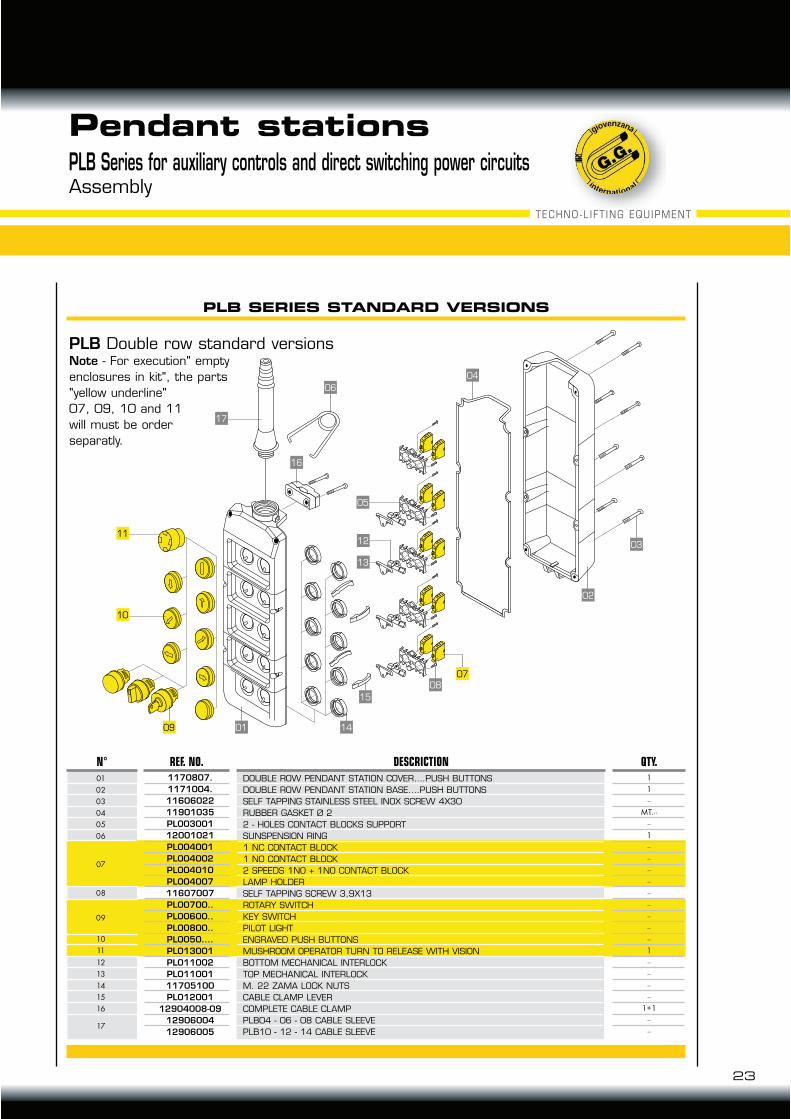
Pendant stationsPLB Series for auxiliary controls and direct switching power circuitsAssembly
17
11
10
09 01
15
14
08
07
03
02
04
06
05
12
13
16
PLB SERIES STANDARD VERSIONS
PLB Double row standard versionsNote - For execution" empty
enclosures in kit", the parts
"yellow underline"
07, 09, 10 and 11
will must be order
separatly.
DOUBLE ROW PENDANT STATION COVER….PUSH BUTTONS
DOUBLE ROW PENDANT STATION BASE….PUSH BUTTONS
SELF TAPPING STAINLESS STEEL INOX SCREW 4X30
RUBBER GASKET Ø 2
2 - HOLES CONTACT BLOCKS SUPPORT
SUNSPENSION RING
1 NC CONTACT BLOCK
1 NO CONTACT BLOCK
2 SPEEDS 1NO + 1NO CONTACT BLOCK
LAMP HOLDER
SELF TAPPING SCREW 3,9X13
ROTARY SWITCH
KEY SWITCH
PILOT LIGHT
ENGRAVED PUSH BUTTONS
MUSHROOM OPERATOR TURN TO RELEASE WITH VISION
BOTTOM MECHANICAL INTERLOCK
TOP MECHANICAL INTERLOCK
M. 22 ZAMA LOCK NUTS
CABLE CLAMP LEVER
COMPLETE CABLE CLAMP
PLB04 - 06 - 08 CABLE SLEEVE
PLB10 - 12 - 14 CABLE SLEEVE
1
1
··
MT.··
··
1
··
··
··
··
··
··
··
··
··
1
··
··
··
··
1+1
··
··
1170807.1171004.1160602211901035PL00300112001021PL004001PL004002PL004010PL00400711607007PL00700..PL00600..PL00800..PL0050....PL013001PL011002PL01100111705100PL012001
12904008-091290600412906005
N° QTY.REF. NO. DESCRICTION
24
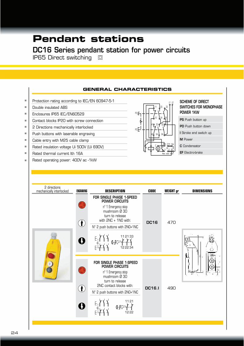
Pendant stationsDC16 Series pendant station for power circuitsIP65 Direct switching
GENERAL CHARACTERISTICS
Protection rating according to IEC/EN 60947-5-1
Double insulated ABS
Enclosures IP65 IEC/EN60529
Contact blocks IP20 with screw connection
2 Directions mechanically interlocked
Push buttons with laserable engraving
Cable entry with M25 cable clamp
Rated insulation voltage Ui 500V (Ui 690V)
Rated thermal current Ith 16A
Rated operating power: 400V ac -1kW
470
WEIGHT grENGRAVING DIMENSIONS
490
CODE
DC16
DC16.I
FOR SINGLE PHASE 1-SPEED POWER CIRCUITS
N° 2 push buttons with 2NO+1NC
DESCRIPTION
n° 1 Emergency stop mushroom Ø 30turn to release
with 2NC + 1NO with:
11
12
21
22
33
34
FOR SINGLE PHASE 1-SPEEDPOWER CIRCUITS
N° 2 push buttons with 2NO+1NC
n° 1 Emergency stop mushroom Ø 30turn to release
2NC contact blocks with:
11
12
21
22
2 directionsmechanically interlocked
SCHEME OF DIRECT SWITCHES FOR MONOPHASE POWER 1KW
PS Push button up
PD Push button down
I Stroke end switch up
M Power
C Condensator
EF Electro-brake
L1
11 23 33
12
PS
PD
24 34
41 53 63
645442
I E F
C YZ
MV X W
U
L2
WEIGHT gr DIMENSIONS
FOR SINGLE-THREE PHASES1-SPEED POWER CIRCUIT
DESCRIPTION CODEENGRAVING
25
TECHNO-LIFT ING EQUIPMENT
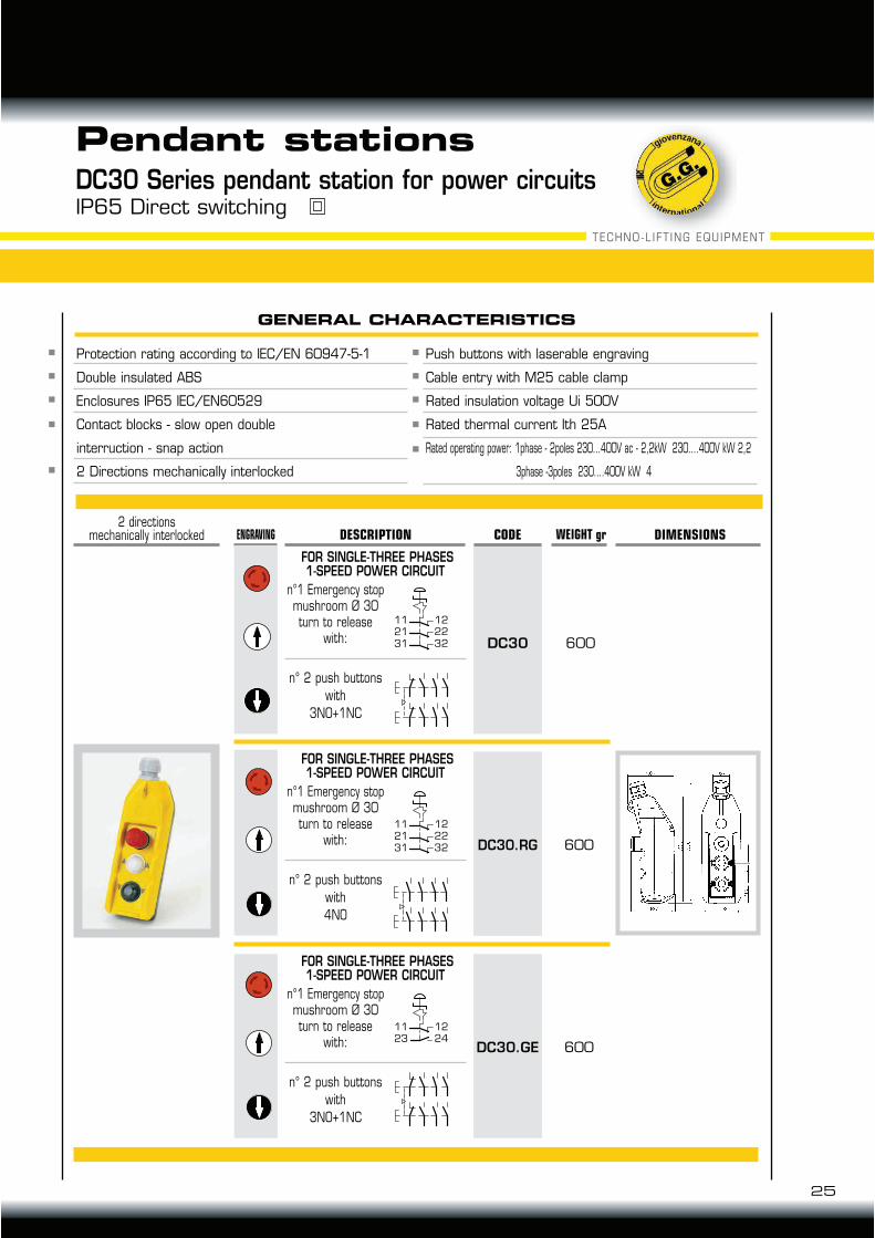
Pendant stationsDC30 Series pendant station for power circuitsIP65 Direct switching
GENERAL CHARACTERISTICS
600
600
600
n°1 Emergency stopmushroom Ø 30turn to release
with:
n° 2 push buttons
with
3NO+1NC
n°1 Emergency stopmushroom Ø 30turn to release
with:
n° 2 push buttons
with
4NO
n°1 Emergency stopmushroom Ø 30turn to release
with:
n° 2 push buttons
with
3NO+1NC
FOR SINGLE-THREE PHASES1-SPEED POWER CIRCUIT
FOR SINGLE-THREE PHASES1-SPEED POWER CIRCUIT
2 directionsmechanically interlocked
DC30
DC30.RG
DC30.GE
Protection rating according to IEC/EN 60947-5-1
Double insulated ABS
Enclosures IP65 IEC/EN60529
Contact blocks - slow open double
interruction - snap action
2 Directions mechanically interlocked
Push buttons with laserable engraving
Cable entry with M25 cable clamp
Rated insulation voltage Ui 500V
Rated thermal current Ith 25A
Rated operating power: 1phase - 2poles 230...400V ac - 2,2kW 230....400V kW 2,2
3phase -3poles 230....400V kW 4
11 12
21 22
31 32
11 12
21 22
31 32
11 12
23 24
PLOO5004PL005019
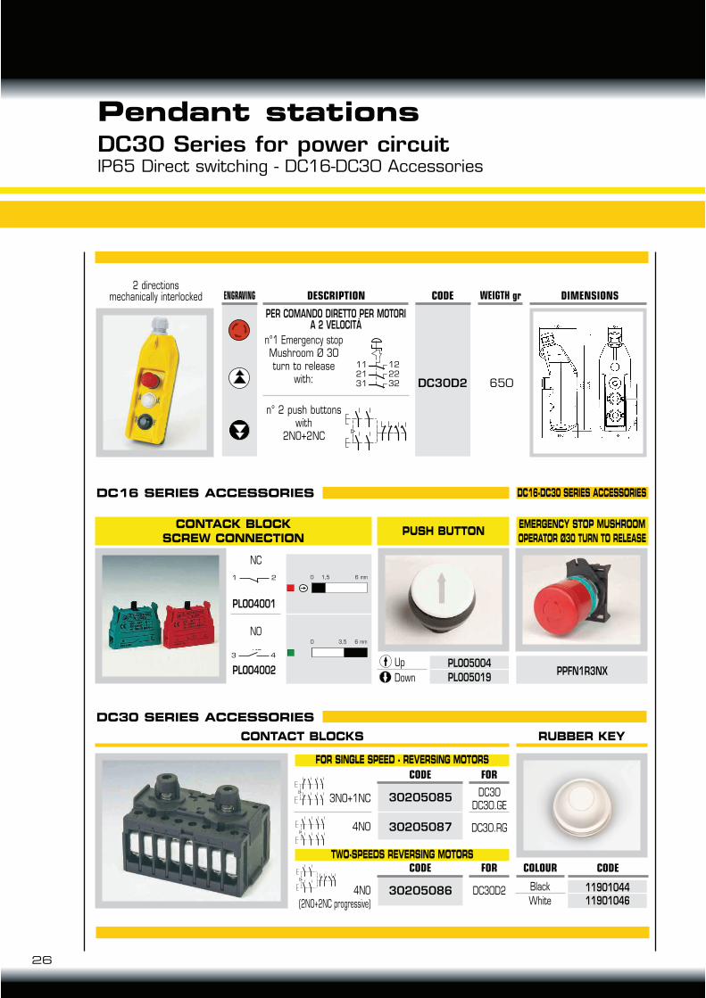
Pendant stationsDC30 Series for power circuitIP65 Direct switching - DC16-DC30 Accessories
26
CONTACT BLOCKS RUBBER KEY
FOR SINGLE SPEED - REVERSING MOTORS
TWO-SPEEDS REVERSING MOTORS
3NO+1NC
4NO
4NO(2NO+2NC progressive)
DC30DC30.GE
DC30.RG
DC30D2
30205085
30205087
30205086
650
WEIGTH gr DIMENSIONS
n°1 Emergency stopMushroom Ø 30 turn to release
with:
n° 2 push buttons with
2NO+2NC
PER COMANDO DIRETTO PER MOTORIA 2 VELOCITÀ
DESCRIPTION2 directions
mechanically interlocked CODE
DC30D2
ENGRAVING
11 12
21 22
31 32
DC16 SERIES ACCESSORIES DC16-DC30 SERIES ACCESSORIES
DC30 SERIES ACCESSORIES
CONTACK BLOCK
SCREW CONNECTIONPUSH BUTTON
EMERGENCY STOP MUSHROOM
OPERATOR Ø30 TURN TO RELEASE
Up
Down
Black
White
PPFN1R3NX
1190104411901046
6 mm3,5
6 mm
NC
NO
PLOO4001
PLOO4002
0
21 0 1,5
43
NO
CODE
CODE COLOUR
FOR
FOR CODE
1323
33
11
21
43
53
63 6
45444
22
12
34
24
14
27
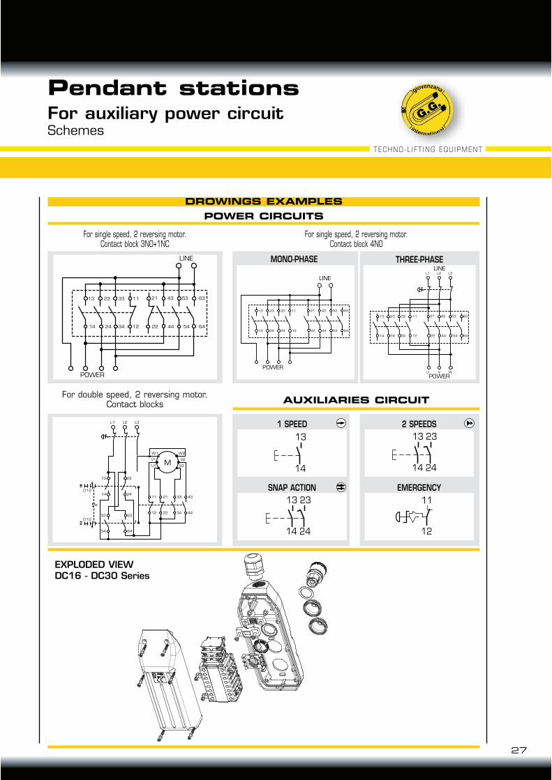
TECHNO-LIFT ING EQUIPMENT
POWER CIRCUITS
EXPLODED VIEWDC16 - DC30 Series
For single speed, 2 reversing motor.Contact block 3NO+1NC
For single speed, 2 reversing motor.Contact block 4NO
AUXILIARIES CIRCUIT
MOTORE
LINEA
6454442212342414
11332313 63534321
MOTORE
LINEA
L1 L2 L3
U V W
6454442212342414
11332313 63534321
MOTORE
LINEA
6353432111332313
6454442212342414
L1
13 23
14
53 6312 22 34 44
11 21 33 43
W2
V2
U2
W1
MV1
U1
0 12
0 12
54 64
24
L2 L3
For double speed, 2 reversing motor.Contact blocks
Pendant stationsFor auxiliary power circuitSchemes
13
14
1 SPEED
13
14
23
24
SNAP ACTION
13
14
23
24
2 SPEEDS
11
12
EMERGENCY
MONO-PHASE THREE-PHASE
DROWINGS EXAMPLES
LINE
LINE
LINE
POWERPOWER
POWER

28
Pendant stationsTLP Light SeriesIP65
GENERAL CHARACTERISTIC
DESCRIPTION CODE WEIGHT grENGRAVING SCHEMS DIMENSIONS
TLP1B.AL
TLP1.EPP
TLP1.VPP
TLP1.ESR
120
120
120
120
Allarmmushroom
operator Ø40momentary
with 1 contact block NC
EmergencyEN ISO 13850
emergency stop Ø40Push-pull
with 1 contact block NC
EmergencyEN ISO 13850
emergency stop Ø40Push-pull
with visionwith 1 contact
block NC
EmergencyEN ISO 13850
emergency stop Ø40Release
with 1 contact block NC
52
48 12.570
80
64
M20
34
52
48 12.570
80
64
M20
34
52
48 12.570
80
64
M20
34
52
48 12.570
80
64
M20
34
Lifting platform and tails lift application
In conformity to IEC/EN 60947-5-1, UNI EN 1570
Box in thermoplastic - Shock and heat resistance
IP65 Double insulation IEC/EN60529
Contact blocks IP20 with spring connection
Two directions mechanically interlocked
Push buttons laser engraving
Pendant or solid fixing
Skin stop cable gland M20
TECHNO-LIFT ING EQUIPMENT
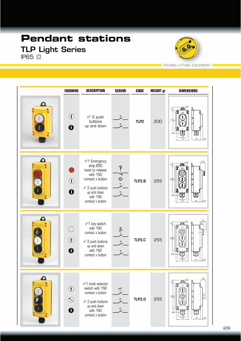
Pendant stationsTLP Light SeriesIP65
DESCRIPTION CODE WEIGHT grENGRAVING SCHEMI DIMENSIONS
TLP3.D
TLP2
TLP3.B
TLP3.C
255
200
255
255
n°1 knob selector switch with 1NOcontact x button
n° 2 push buttonsup and down
with 1NOcontact x button
n° 2 pushbuttons
up and down
n°1 Emergency stop Ø30
twist to releasewith 1NC
contact x button
n° 2 push buttonsup and down
with 1NOcontact x button
n°1 key switch with 1NO
contact x button
n° 2 push buttonsup and down
with 1NOcontact x button
52
48 12.5
30Ø 10
70
15
01
6
13
4
M20
52
48 12.5
Ø 10
70
11
51
6
99
M20
52
48 12.5
Ø 10
70
15
01
6
13
4
M20
31.5
52
48 12.5
35Ø 10
20.5
70
15
01
6
13
4
M20
29
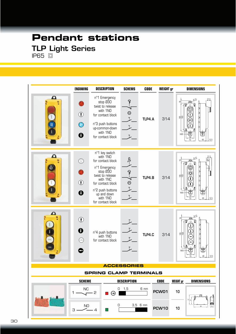
Pendant stationsTLP Light SeriesIP65
DESCRIPTION CODE WEIGHT grENGRAVING SCHEMS DIMENSIONS
TLP4.A
TLP4.B
TLP4.C
314
314
314
n°1 Emergency stop Ø30
twist to releasewith 1NO
for contact block
n°3 push buttons up-common-down
with 1NOfor contact block
n°1 key switch with 1NO
for contact block
n°1 Emergency stop Ø30
twist to releasewith 1NC
for contact block
n°2 push buttonsup and down
with 1NOfor contact block
n°4 push buttonswith 1NO
for contact block
52
48 12.5
31.5Ø 10
70
185
16
169
M20
31.5
Ø 1020.5
169
M20
52
48 12.570
185
16
52
48 12.5
Ø 10
70
185
16
169
M20
30
SPRING CLAMP TERMINALS
ACCESSORIES
DIMENSIONS
PCWO1
PCW10
CODE
10
10
WEIGHT gr
6 mm0 3,5
DESCRIPTION
0 1,5 6 mm
SCHEME
2
NC
1
43
NO 38 10
2127
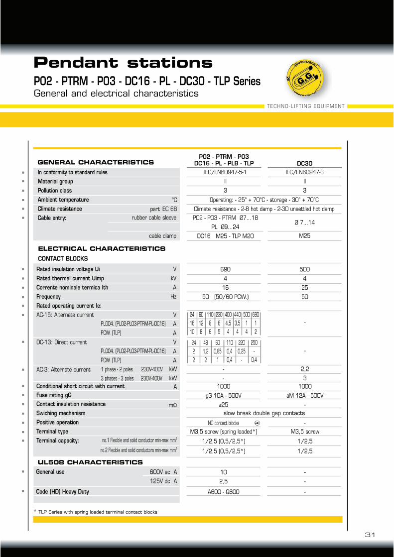
P02 - PTRM - P03 - DC16 - PL - DC30 - TLP SeriesGeneral and electrical characteristics
Pendant stations
Rated insulation voltage Ui
Rated thermal current Uimp
Corrente nominale termica Ith
Frequency
Rated operating current Ie:
AC-15: Alternate current
DC-13: Direct current
AC-3: Alternate current
Conditional short circuit with current
Fuse rating gG
Contact insulation resistance
Swiching mechanism
Positive operation
Terminal type
Terminal capacity:
PL004. (PL02-PL03-PTRM-PL-DC16)
PCW. (TLP)
PL004. (PL02-PL03-PTRM-PL-DC16)
PCW. (TLP)
1 phase - 2 poles 230V-400V
3 phases - 3 poles 230V-400V
1000
gG 10A - 500V
25
NC contact blocks
1/2,5 (0,5/2,5*)
1/2,5 (0,5/2,5*)
10
2,5
A600 - Q600
-
-
1000
aM 12A - 500V
-
-
1/2,5
1/2,5
-
-
-
-
-
2,2
3
500
4
25
50
690
4
16
50 (50/60 PCW.)
GENERAL CHARACTERISTICSP02 - PTRM - P03
DC16 - PL - PLB - TLP
V
kV
A
Hz
600V ac A
125V dc A
V
A
A
V
A
A
kW
kW
no.1 Flexible and solid conductor min-max mm2
no.2 Flexible and solid conductors min-max mm2
°C
part IEC 68
rubber cable sleeve
cable clamp
60
12
8
24
16
10
230
6
5
400
4,5
4
440
3,5
4
500
1
4
690
1
2
110
8
6
48
1,2
2
24
2
2
110
0,4
0,4
220
0,25
-
250
-
0,4
60
0,85
1
In conformity to standard rules
Material group
Pollution class
Ambient temperature
Climate resistance
Cable entry:
IEC/EN60947-5-1
II
3
P02 - P03 - PTRM Ø7...18
PL Ø9...24
DC16 M25 - TLP M20
DC30
IEC/EN60947-3
II
3
Ø 7...14
M25
A
m!
ELECTRICAL CHARACTERISTICS
CONTACT BLOCKS
uL508 CHARACTERISTICS
slow break double gap contacts
M3,5 screw (spring loaded*) M3,5 screw
31
TECHNO-LIFT ING EQUIPMENT
General use
Code (HD) Heavy Duty
Operating: - 25° + 70°C - storage - 30° + 70°C
Climate resistance - 2-8 hot damp - 2-30 unsettled hot damp
* TLP Series with spring loaded terminal contact blocks

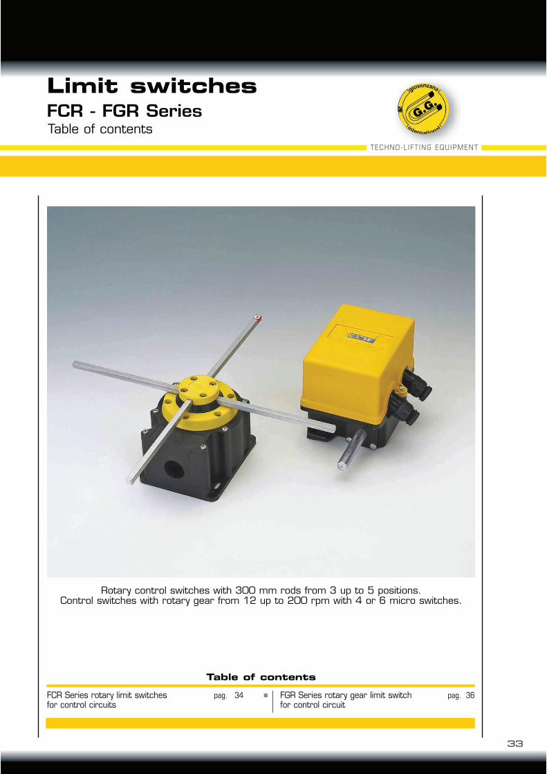
FCR Series rotary limit switchesfor control circuits
FCR - FGR Series
33
Table of contents
TECHNO-LIFT ING EQUIPMENT
Limit switches
Rotary control switches with 300 mm rods from 3 up to 5 positions.Control switches with rotary gear from 12 up to 200 rpm with 4 or 6 micro switches.
FGR Series rotary gear limit switchfor control circuit
Table of contents
pag. 36pag. 34
According to IEC/EN60947-3, uL508
Certifications:
Rated insulation voltage Ui
Rated thermal current Ithe
Frequency
Rated thermal current: AC-21A - AC-22A
AC23A - 3x3
Rated short circuit withstand current (gG 20A-690V)
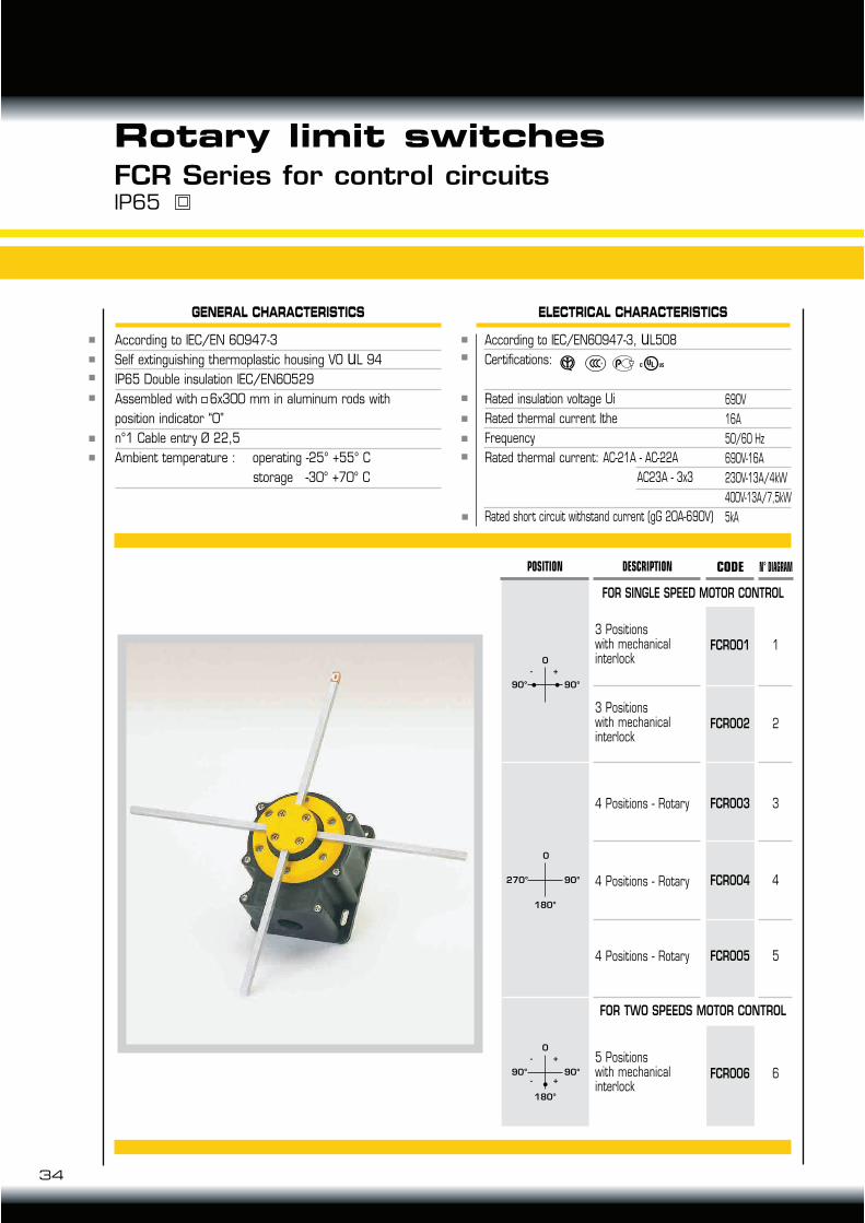
FCR Series for control circuitsIP65
Rotary limit switches
GENERAL CHARACTERISTICS
According to IEC/EN 60947-3
Self extinguishing thermoplastic housing VO uL 94
IP65 Double insulation IEC/EN60529
Assembled with 6x300 mm in aluminum rods with
position indicator “0”
n°1 Cable entry Ø 22,5
Ambient temperature : operating -25° +55° C
storage -30° +70° C
ELECTRICAL CHARACTERISTICS
690V
16A
50/60 Hz
690V-16A
230V-13A/4kW
400V-13A/7,5kW
5kA
DESCRIPTION
FCR001
FCR002
FCR003
FCR004
FCR005
1
2
3
4
5
FCR006 6
POSITION CODE
3 Positionswith mechanical interlock
4 Positions - Rotary
4 Positions - Rotary
4 Positions - Rotary
3 Positionswith mechanical interlock
5 Positionswith mechanical interlock
N° DIAGRAM
FOR SINGLE SPEED MOTOR CONTROL
FOR TWO SPEEDS MOTOR CONTROL
34
0
- +
90° 90°
0
270°
180°
90°
0- +
- +90° 90°
180°
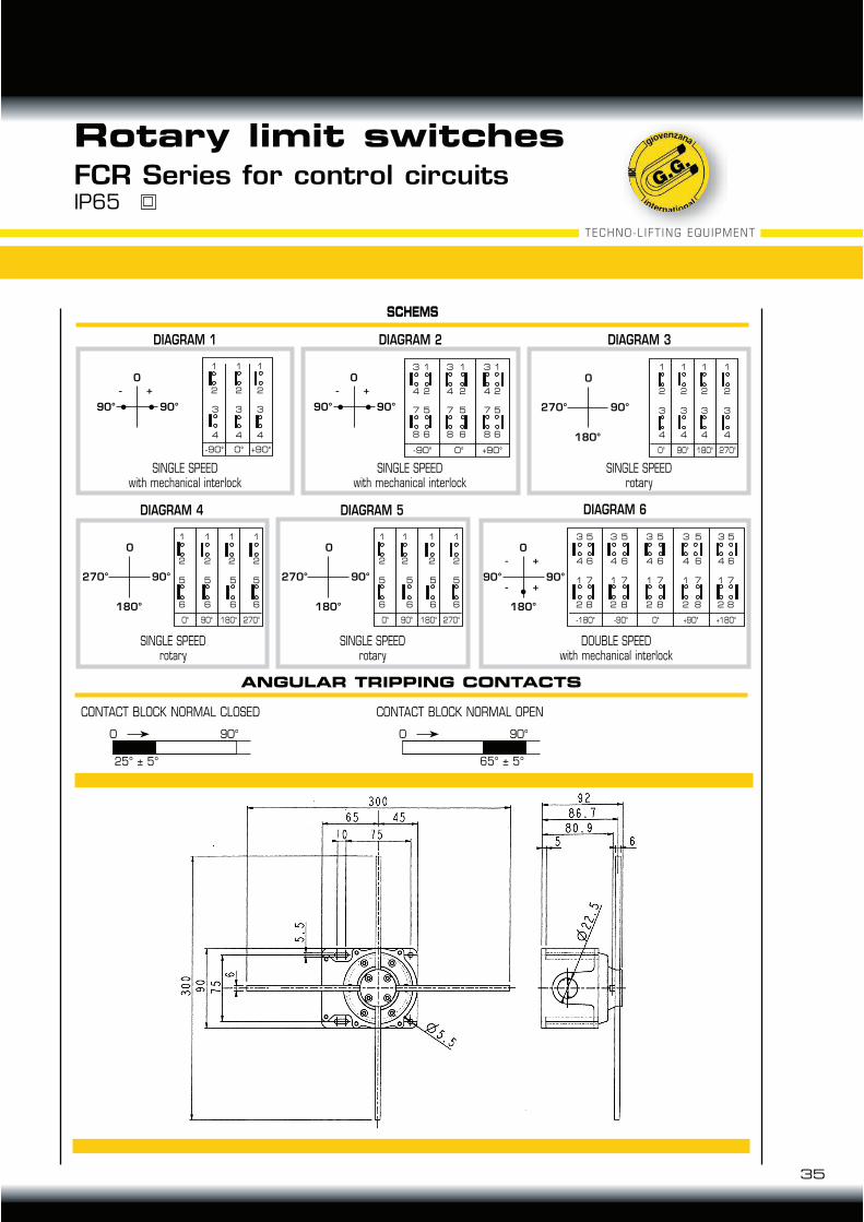
SCHEMS
ANGULAR TRIPPING CONTACTS
2
1
2
1
2
1
2
1
6
5
6
5
6
5
6
5
90°0° 180° 270°
DIAGRAM 4
4
3
2
1
6
5
8
7
4
3
2
1
6
5
8
7
4
3
2
1
6
5
8
7
4
3
2
1
6
5
8
7
4
3
2
1
6
5
8
7
0°-180° -90° +90° +180°
DIAGRAM 6
DOUBLE SPEEDwith mechanical interlock
2
1
2
1
2
1
2
1
6
5
6
5
6
5
6
5
90°0° 180° 270°
DIAGRAM 5
4
3
4
3
4
3
2
1
2
1
2
-90° 0° +90°
1
DIAGRAM 1
SINGLE SPEEDwith mechanical interlock
4
3
2
1
4
-90° 0° +90°
3
2
1
4
3
2
1
8
7
6
5
8
7
6
5
8
7
6
5
DIAGRAM 2
SINGLE SPEEDwith mechanical interlock
2
1
2
1
2
1
2
1
4
3
4
3
4
3
4
3
90°0° 180° 270°
DIAGRAM 3
FCR Series for control circuitsIP65
Rotary limit switches
SINGLE SPEEDrotary
SINGLE SPEEDrotary
SINGLE SPEEDrotary
CONTACT BLOCK NORMAL CLOSED CONTACT BLOCK NORMAL OPEN
0
- +
90° 90°
0
- +
90° 90°
0
270°
180°
90°
0
270°
180°
90°
0
270°
180°
90°
0
- +
- +
90° 90°
180°
35
TECHNO-LIFT ING EQUIPMENT
0 090° 90°
25° ± 5° 65° ± 5°
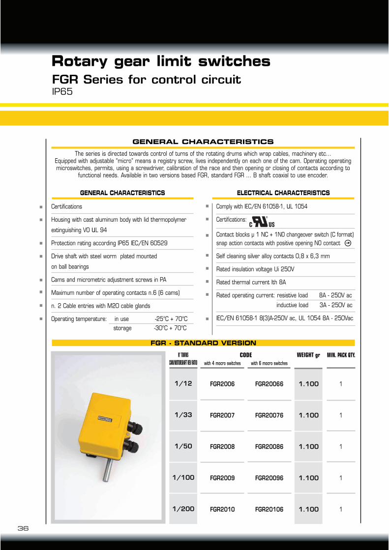
Comply with IEC/EN 61058-1, uL 1054
Certifications:
Contact blocks µ 1 NC + 1NO changeover switch (C format)
snap action contacts with positive opening NO contact
Self cleaning silver alloy contacts 0,8 x 6,3 mm
Rated insulation voltage Ui 250V
Rated thermal current Ith 8A
Rated operating current: resistive load 8A - 250V ac
inductive load 3A - 250V ac
IEC/EN 61058-1 8(3)A-250V ac, UL 1054 8A - 250Vac
36
FGR - STANDARD VERSION
FGR Series for control circuitIP65
GENERAL CHARACTERISTICS
The series is directed towards control of turns of the rotating drums which wrap cables, machinery etc...Equipped with adjustable “micro” means a registry screw, lives independently on each one of the cam. Operating operating microswitches, permits, using a screwdriver, calibration of the race and then opening or closing of contacts according to
functional needs. Available in two versions based FGR, standard FGR ... B shaft coaxial to use encoder.
Certifications
Housing with cast aluminum body with lid thermopolymer
extinguishing VO uL 94
Protection rating according IP65 IEC/EN 60529
Drive shaft with steel worm plated mounted
on ball bearings
Cams and micrometric adjustment screws in PA
Maximum number of operating contacts n.6 (6 cams)
n. 2 Cable entries with M20 cable glands
Operating temperature: in use -25°C + 70°C
storage -30°C + 70°C
GENERAL CHARACTERISTICS
CODE
with 6 mocro switches
FGR2006
FGR2007
FGR2008
FGR2009
FGR2010
1/12
1/33
1/50
1/100
1/200
WEIGHT gr
1.100
1.100
1.100
1.100
1.100
1
1
1
1
1
MIN. PACK QTY.
FGR20066
FGR20076
FGR20086
FGR20096
FGR20106
with 4 mocro switches
Rotary gear limit switches
ELECTRICAL CHARACTERISTICS
N° TOURNS
CAM/MOTORSHAFT REV RATIO
A
B
C
D
E
F
a
b
c
d
e
CAM No. 1
CAM No. 2
CAM No. 3
CAM No. 4
CAM No. 5
CAM No. 6
37
TECHNO-LIFT ING EQUIPMENT
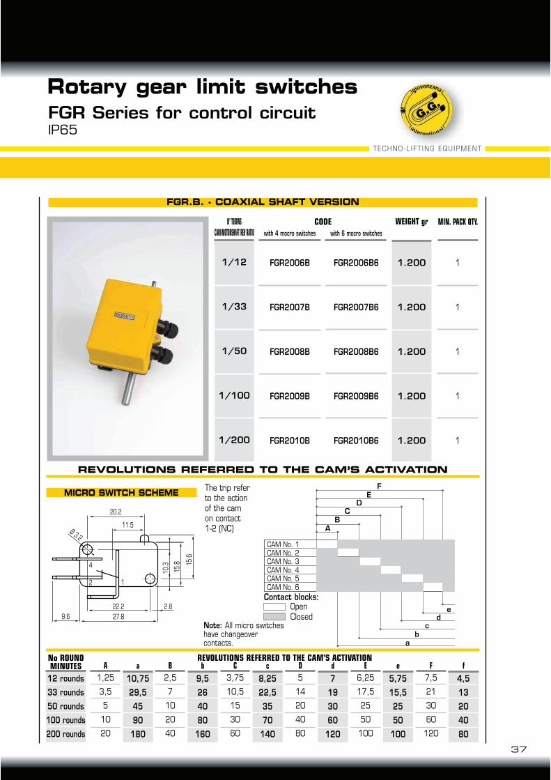
FGR.B. - COAXIAL SHAFT VERSION
MICRO SWITCH SCHEME
FGR Series for control circuitIP65
CODE
with 6 mocro switches
N° TOURNS
CAM/MOTORSHAFT REV RATIO
FGR2006B
FGR2007B
FGR2008B
FGR2009B
FGR2010B
1/12
1/33
1/50
1/100
1/200
WEIGHT gr
1.200
1.200
1.200
1.200
1.200
1
1
1
1
1
MIN. PACK QTY.
FGR2006B6
FGR2007B6
FGR2008B6
FGR2009B6
FGR2010B6
with 4 mocro switches
Rotary gear limit switches
No ROUNDMINUTES
1,25
3,5
5
10
20
12 rounds
33 rounds
50 rounds
100 rounds
200 rounds
REVOLUTIONS REFERRED TO THE CAM’S ACTIVATIONa
10,75
29,5
45
90
180
A
7,5
21
30
60
120
f
4,5
13
20
40
80
F
6,25
17,5
25
50
100
e
5,75
15,5
25
50
100
E
5
14
20
40
80
d
7
19
30
60
120
D
3,75
10,5
15
30
60
c
8,25
22,5
35
70
140
C
2,5
7
10
20
40
b
9,5
26
40
80
160
B
The trip referto the actionof the camon contact1-2 (NC)
Contact blocks:OpenClosed
Note: All micro switches have changeovercontacts.
REVOLUTIONS REFERRED TO THE CAM’S ACTIVATION
20.2
Ø 3.2
11.5
12
4
22.2
27.8
2.8
9.6
15
.6
15
.8
10
.3
38
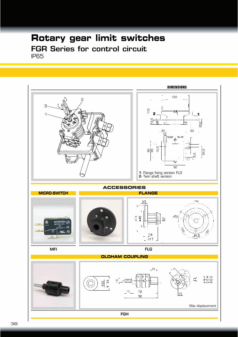
FGR Series for control circuitIP65
Rotary gear limit switches
FLANGEMICRO-SWITCH
OLDHAM COUPLING
Max displacement
ACCESSORIES
DIMENSIONS
1- Flange fixing version FLG 2- Twin shaft version
12
FLG
FGH
MFI
122
6030
90
54
,590
11
01
9,5
Ø6
Ø1
2
65
10
,5
6,5
10

TECHNO-LIFT ING EQUIPMENT
39
Scudo - Prisma - Navale SeriesTable of contents
Slip rings
Scudo - Prisma - Navale SeriesCharacteristic
Scudo - Prisma - Navale SeriesVersions
20 - 50A Slip rings from 3 up to 16 rings with open frameor protection rating up to IP65.
Scudo - Prisma - Navale SeriesAccessories and replacement
Warning hornsAA Series
TABLE OF CONTENTS
pag. 41
pag. 42
pag. 43
pag. 40

40
SCUDO
CHARACTERISTICS
Slip ringsScudo - Prisma - Navale SeriesCharacteristics
Slip rings are used to tranfer electrical
signal and power energy between stator
and a rotor or viceversa. They are com-
prised of 3 or more in graphite or metal
contacts, mounted on the steel shaft the
brushes are all replace and are in graphite
on Prisma and Navale Series in copper on
Scudo Series
OPERATING TIMEThe operating life of a slip ring is dependant upon the rotation speed and thedynamic stability.
CURRENT RATINGCapacity can be increasing by connecting in series or parallel two or more slip rings.
BRUSHES IN GRAPHITEThey are mainly used on low-medium speed applications. they are the most commonin particular when more circuits are required as they ensure a very good connectionthey withstand low and high temperatures, aggressive environments with presence of chemicals and unidity.
SPEED OPERATIONMax rotation speed 20 turns 1’.
Rated insulationvoltage Ui 690V
Rated operatingvoltage Ue 500Vac
Rated operating current 20A. Intermittent working 30A.
Close frame version withprotection ratedIEC/EN60529 IP51
Modularity: from 3up to 15 80 mm Ø rings
Cu brushes
42 mm Ø shaft
Pvc 147 mm Ø housingand terminals cover
Ambient temperature:+ 60° C - 30° C.
PRISMA
Rated insulationvoltage Ui 690V
Rated operatingvoltage Ue 500Vac
Rated operatingcurrent 50A
Open frame
Modularity: from 3 up to 16100 mm ø rings
Brushes in graphite
51 mm Ø shaft
NAVALE
Rated insulationvoltage Ui 690V
Rated operatingvoltage Ue 500Vac
Rated operatingcurrent 50A
Close frame version withprotection ratedIEC/EN60529 IP65
Modularity: from 3 up to 16100 mm ø rings
Brushes in graphite
51 mm Ø shaftwith roller bearingsand O-ring
280 mm Ø power coatedalluminium housing withprotection against aggressive environments

TECHNO-LIFT ING EQUIPMENT
41
N° RINGS
Slip ringsScudo - Prisma - Navale SeriesVersions
3040209130402092304020933040209430402095 3040209630402097304020983040209930402100304021013040210230402103
3456789
101112131415
SCUDO 20A IP51 SERIE
DIMENSIONS ACODE
180195210225240255270285300315330345360
N° RINGS
3040203730402038304020393040204030402041 304020423040204330402044304020453040204630402047304020483040204930402050
3456789
10111213141516
PRISMA 50A IP00 SERIE
DIM. A DIM. BCODE
143162181200219238257276295314333352371390
170190210230250270290310330350370390410430
N° RINGS
3040300130403002304030033040300430403005304030063040300730403008304030093040301030403011304030123040301330403014
3456789
10111213141516
187
40
50
87
Ø 100 M 10
Ø 51P 1.5
Ø 1
20
Ø 45
A
B20
30
19
20
30
60*/
66**
14
Ø 280
B
A1
00
Ø 51 P 1.5
NAVALE 50A IP65 SERIE
DIM. A DIM. BCODE
375265
570470
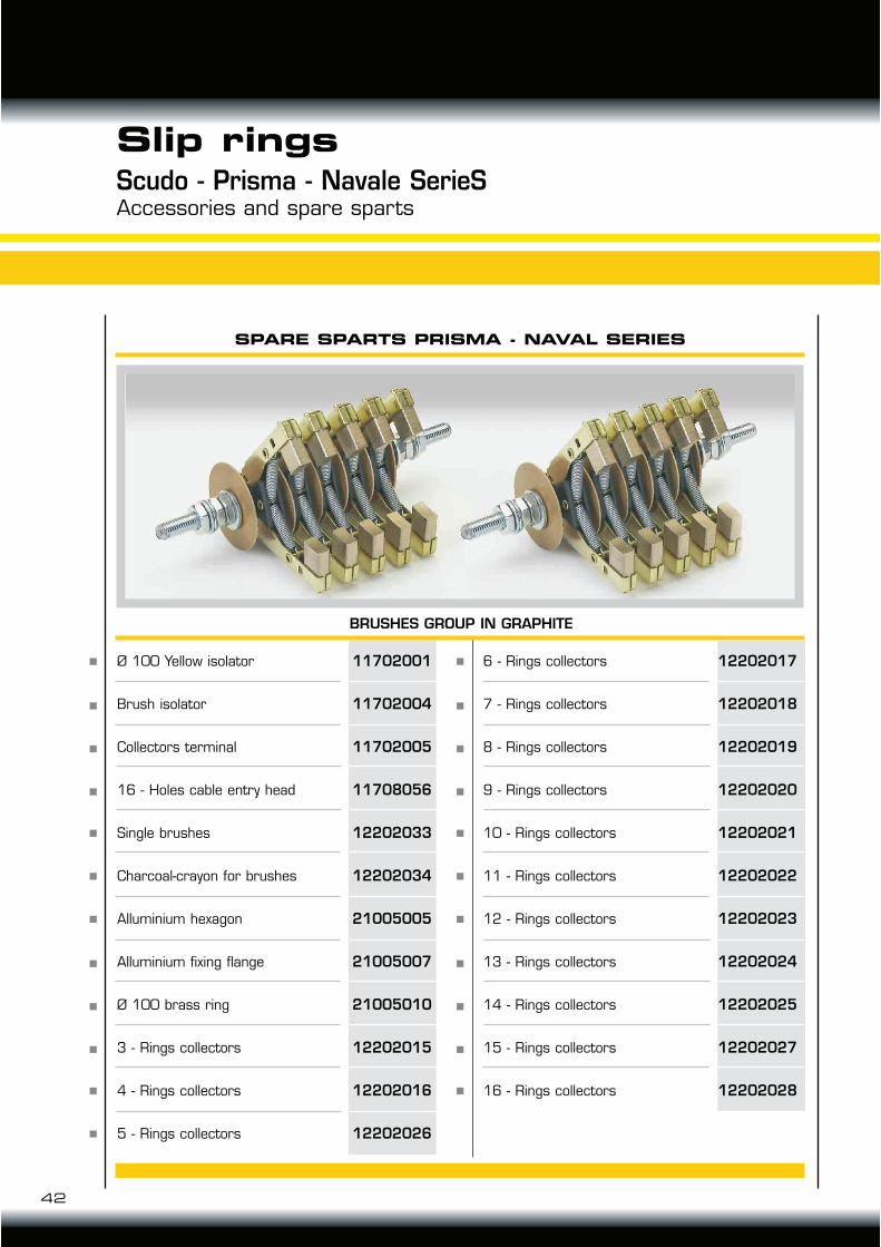
Ø 100 Yellow isolator
Brush isolator
Collectors terminal
16 - Holes cable entry head
Single brushes
Charcoal-crayon for brushes
Alluminium hexagon
Alluminium fixing flange
Ø 100 brass ring
3 - Rings collectors
4 - Rings collectors
5 - Rings collectors
42
Scudo - Prisma - Navale SerieSAccessories and spare sparts
Slip rings
SPARE SPARTS PRISMA - NAVAL SERIES
11702001
11702004
11702005
11708056
12202033
12202034
21005005
21005007
21005010
12202015
12202016
12202026
6 - Rings collectors
7 - Rings collectors
8 - Rings collectors
9 - Rings collectors
10 - Rings collectors
11 - Rings collectors
12 - Rings collectors
13 - Rings collectors
14 - Rings collectors
15 - Rings collectors
16 - Rings collectors
12202017
12202018
12202019
12202020
12202021
12202022
12202023
12202024
12202025
12202027
12202028
BRUSHES GROUP IN GRAPHITE
TECHNO-LIFT ING EQUIPMENT
415
210
90
42
24 AC
48 AC
110 AC
230 AC
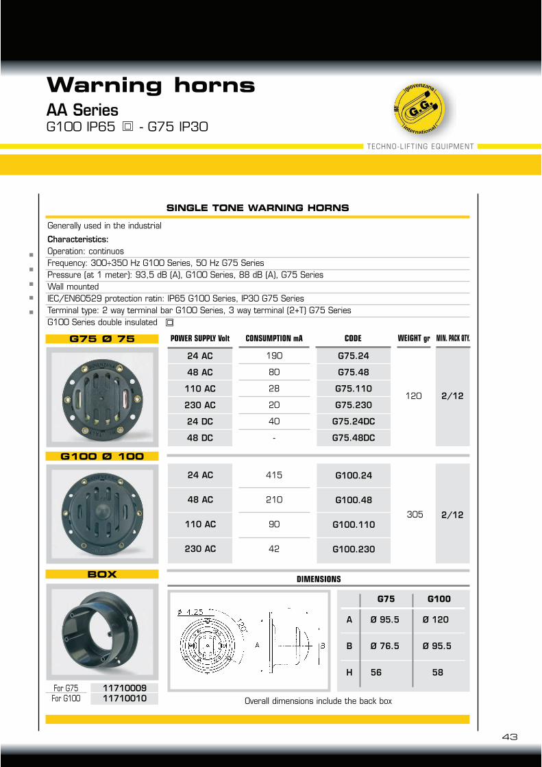
Generally used in the industrial
Characteristics:
Operation: continuos
Frequency: 300÷350 Hz G100 Series, 50 Hz G75 Series
Pressure (at 1 meter): 93,5 dB (A), G100 Series, 88 dB (A), G75 Series
Wall mounted
IEC/EN60529 protection ratin: IP65 G100 Series, IP30 G75 Series
Terminal type: 2 way terminal bar G100 Series, 3 way terminal (2+T) G75 Series
G100 Series double insulated
AA Series
43
G100 IP65 - G75 IP30
Warning horns
SINGLE TONE WARNING HORNS
G75 Ø 75
G100 Ø 100
BOX
For G75For G100 Overall dimensions include the back box
1171000911710010
G100.24
G100.48
G100.110
G100.230
2/12305
DIMENSIONS
A
B
H
Ø 95.5
Ø 76.5
56
Ø 120
Ø 95.5
58
G75 G100
120 2/12
G75.24
G75.48
G75.110
G75.230
G75.24DC
G75.48DC
24 AC
48 AC
110 AC
230 AC
24 DC
48 DC
190
80
28
20
40
-
CONSUMPTION mA CODE WEIGHT grPOWER SUPPLY Volt MIN. PACK QTY.

28 Series fastoon system
30 Series fastoon system
41 Series fastoon system
Wire rope Series ø 8
Light i-beam Series
Heavy i-beam Series
28 - 30 - 41 Series conduct railsExample of installation
TR85 Series Trolley system - Characteristic
TR85 Series Trolley system Characteristics - Calculation for down-current
TR85 Series Trolley system
Calculation line
TR85 Series Trolley system Examples of orders
TR85 Series Trolley system
TR85 Series conductor rails line A plug-in type
TR85 Series Trolley system
TR85 Series conductor rails line B continuos strip type
Conductors CP and CT Series
Spare partsDisconnectors
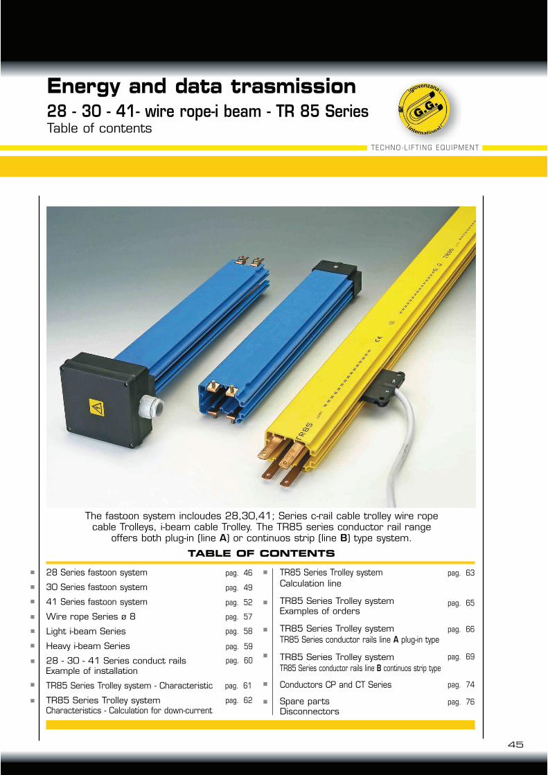
28 - 30 - 41- wire rope-i beam - TR 85 Series
45
Table of contents
TECHNO-LIFT ING EQUIPMENT
Energy and data trasmission
The fastoon system incloudes 28,30,41; Series c-rail cable trolley wire ropecable Trolleys, i-beam cable Trolley. The TR85 series conductor rail range
offers both plug-in (line A) or continuos strip (line B) type system.
TABLE OF CONTENTS
pag. 49
pag. 52
pag. 57
pag. 60
pag. 62
pag. 61
pag. 58
pag. 59
pag. 65
pag. 63
pag. 66
pag. 69
pag. 74
pag. 76
pag. 46
46
1
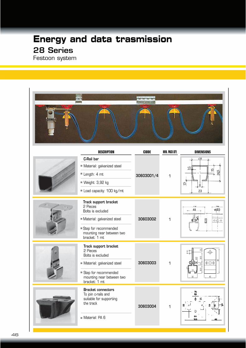
CODE MIN. PACK QTY. DIMENSIONSDESCRIPTION
30603001/4
C-Rail bar
Material: galvanized steel
Length: 4 mt
Weight: 3,92 kg
Load capacity: 100 kg/mt
130603002
Track support bracket2 PiecesBolts is excluded
Material: galvanized steel
Step for recommended mounting near between two bracket: 1 mt
130603003
Track support bracket2 PiecesBolts is excluded
Material: galvanized steel
Step for recommended mounting near between two bracket: 1 mt
130603004
Bracket connectorsTo join c-rails and suitable for supportingthe track
Material: PA 6
4032
13
88
30.5
834.5
M 6
Ø 1
0 15
2
Energy and data trasmission28 SeriesFestoon system
47
TECHNO-LIFT ING EQUIPMENT
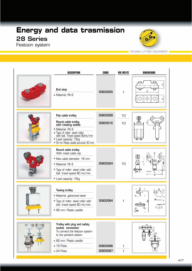
Energy and data trasmission28 SeriesFestoon system
1
22
20
62
CODE MIN. PACK QTY. DIMENSIONSDESCRIPTION
30603005End stop
Material: PA 6
35
Flat cable trolley
Round cable trolleywith rotating saddle
Material: PA 6Type of roller: steel rollerwith ball. Travel speed 80mt/minLoad capacity: 15kg55 mm Plastic saddle (excursion 50 mm)
1030603024
Round cable trolleyWith metal cable clip
Max cable diameter: 18 mm
Material: PA 6
Type of roller: steel roller with ball. travel speed 80 mt/min.
Load capacity: 15kg
Trolley with plug and safety socket connectionTo connect the festoon system to the pendant station
68 mm: Plastic saddle
16 Poles
24 Poles
Towing trolley
Material: galvanized steel
Type of roller: steel roller with ball. travel speed 80 mt/min.
68 mm: Plastic saddle
1
1
30603066
30603067
190
70
27
5Ø 2
2
120
90 90
1030603008
1030603012
130603064
48
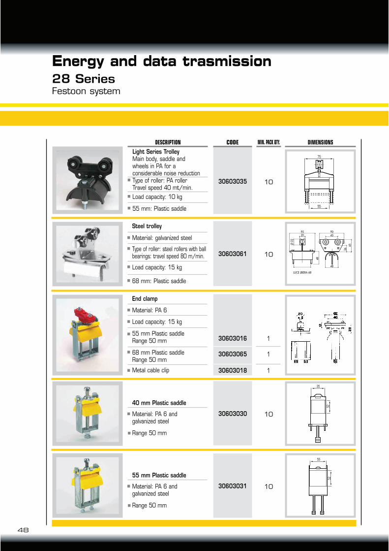
Energy and data trasmission28 SeriesFestoon system
10
75
55
CODE MIN. PACK QTY. DIMENSIONSDESCRIPTION
30603035
Steel trolley
Material: galvanized steel
Type of roller: steel rollers with ball bearings: travel speed 80 m/min.
Load capacity: 15 kg
68 mm: Plastic saddle
1
1
1
30603016
30603065
30603018
End clamp
Material: PA 6
Load capacity: 15 kg
55 mm Plastic saddleRange 50 mm
68 mm Plastic saddleRange 50 mm
Metal cable clip
40 mm Plastic saddle
Material: PA 6 andgalvanized steel
Range 50 mm
35
52
55
52
1030603061
1030603030
55 mm Plastic saddle
Material: PA 6 andgalvanized steel
Range 50 mm
1030603031
Light Series TrolleyMain body, saddle andwheels in PA for aconsiderable noise reductionType of roller: PA rollerTravel speed 40 mt/min.
Load capacity: 10 kg
55 mm: Plastic saddle
49
TECHNO-LIFT ING EQUIPMENT
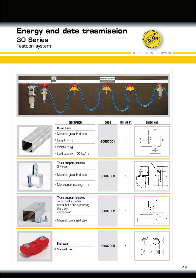
Energy and data trasmission30 SeriesFestoon system
CODE MIN. PACK QTY. DIMENSIONSDESCRIPTION
130607001
C-Rail bars
Material: galvanized steel
Lenght: 4 mt
Weight: 5 kg
Load capacity: 100 kg/mt
130607003
Truck support bracket2 Pieces
Material: galvanized steel
Max support spacing: 1mt
130607002
130607005
Truck support bracketTo connect a C-Railsand suitable for supportingthe trackceiling fixing
Material: galvanized steel
22
20
62
End stop
Material: PA 6
50
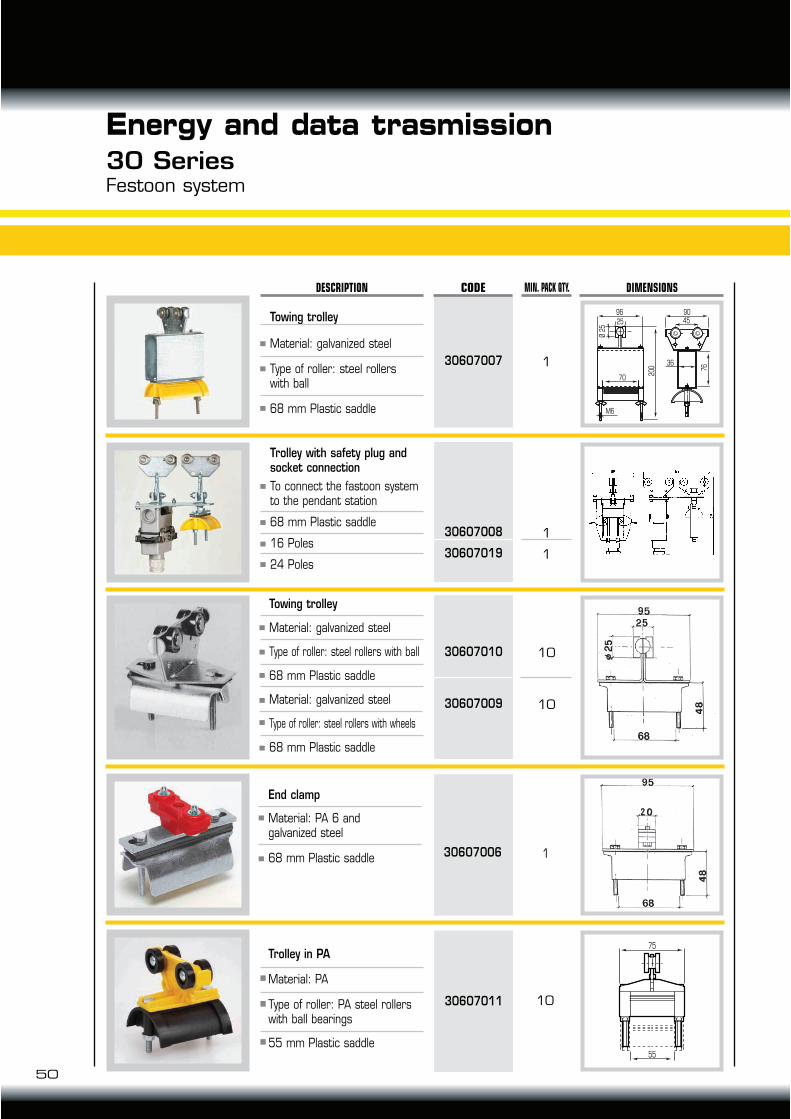
Energy and data trasmission30 SeriesFestoon system
30607010
30607009
Towing trolley
Material: galvanized steel
Type of roller: steel rollers with ball
68 mm Plastic saddle
Material: galvanized steel
Type of roller: steel rollers with wheels
68 mm Plastic saddle
30607006
30607011
10
10
1
96
25
70
36
M6
90
200 76
45
Ø 2
5
CODE MIN. PACK QTY. DIMENSIONSDESCRIPTION
30607007
1
1
30607008
30607019
75
55
Towing trolley
Material: galvanized steel
Type of roller: steel rollerswith ball
68 mm Plastic saddle
Trolley with safety plug and socket connection
To connect the fastoon system to the pendant station
68 mm Plastic saddle
16 Poles
24 Poles
1
End clamp
Material: PA 6 andgalvanized steel
68 mm Plastic saddle
10
Trolley in PA
Material: PA
Type of roller: PA steel rollerswith ball bearings
55 mm Plastic saddle
1
1
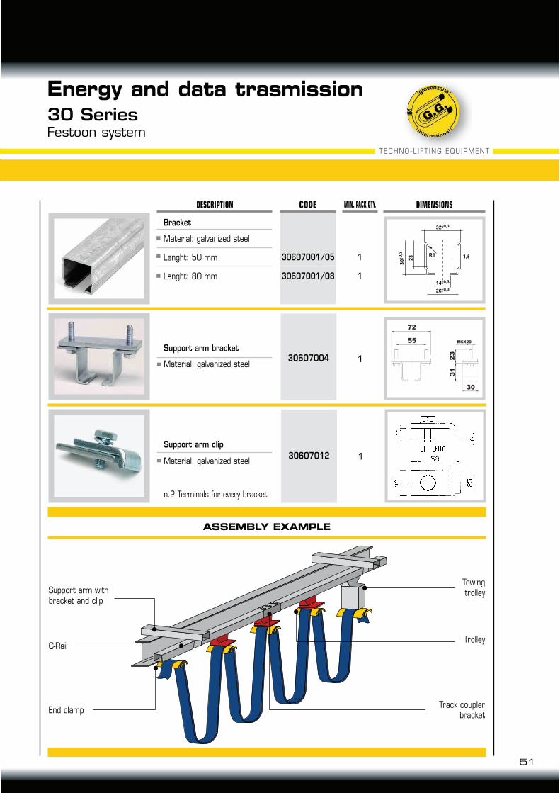
30607001/05
30607001/08
Bracket
Material: galvanized steel
Lenght: 50 mm
Lenght: 80 mm
TECHNO-LIFT ING EQUIPMENT
Energy and data trasmission30 SeriesFestoon system
CODE MIN. PACK QTY. DIMENSIONSDESCRIPTION
130607012
Support arm bracket
Material: galvanized steel
Support arm clip
Material: galvanized steel
n.2 Terminals for every bracket
130607004
ASSEMBLY EXAMPLE
C-Rail
End clampTrack coupler
bracket
Trolley
TowingtrolleySupport arm with
bracket and clip
51

Energy and data trasmission41 SeriesFestoon system
1
1
56
18
7
1820
39
1.5
CODE MIN. PACK QTY. DIMENSIONSDESCRIPTION
30602054
30602001/4
C-Rail bars
Material: galvanized steel
Lenght: 4 mt
Weight: 8 kg
Load capacity: 140 kg/mt
90° Curve 1,5 mt radius*
1 94
4425
25
m 1
0
105
Ø 1260
60
26
30602004
Track support bracketCeiling fixing 2 piecesBolts not included
Material: galvanized steel
Max support spacing:(1 mt recommended)
130602003
Track support bracketWall fixingBolts not included
Material: galvanized steel
Max support spacing:(1 mt recommended)
1
1
30602002
30602034
Track coupler bracketTo join c-rail and suitable for supporting the track
Material: galvanized steel
Double track coupler bracketRecommended for track over 50 mt
Material: galvanized steel
90
61
28
40
44
23
23
M1
2
170
63 80
28
3
46
*The use of the curve requires a mechanical adjustment during assembly line.
52
53
TECHNO-LIFT ING EQUIPMENT
Energy and data trasmission41 SeriesFestoon system
74 20
45
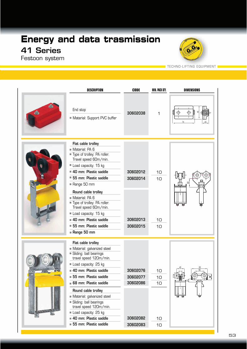
CODE MIN. PACK QTY. DIMENSIONSDESCRIPTION
40
10
10
30602012
30602014
End stop
Material: Support PVC buffer
Flat cable trolley
Material: PA 6
Type of trolley: PA roller.
Travel speed 60m/min.
Load capacity: 15 kg
40 mm: Plastic saddle
55 mm: Plastic saddle
Range 50 mm
10
10
30602013
30602015
Round cable trolley
Material: PA 6
Type of trolley: PA roller.Travel speed 60m/min.
Load capacity: 15 kg
40 mm: Plastic saddle
55 mm: Plastic saddle
Range 50 mm
Ø 3
4
9545
56
36
36
25
10
10
10
30602076
30602077
30602086
Flat cable trolley
Material: galvanized steel
Sliding: ball bearingstravel speed 120m/min.
Load capacity: 25 kg
40 mm: Plastic saddle
55 mm: Plastic saddle
68 mm: Plastic saddle
10
10
30602082
30602083
Round cable trolley
Material: galvanized steel
Sliding: ball bearingstravel speed 120m/min.
Load capacity: 25 kg
40 mm: Plastic saddle
55 mm: Plastic saddle
130602038
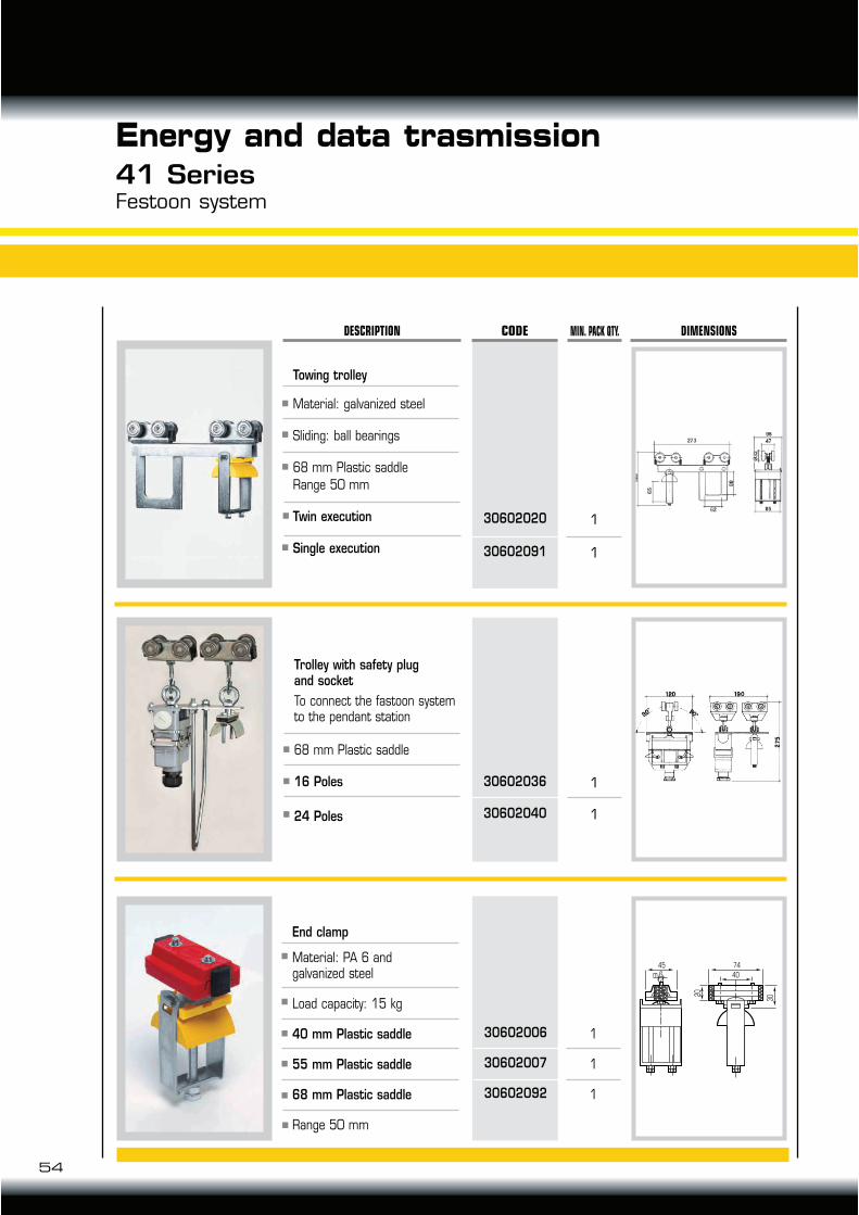
End clamp
Material: PA 6 andgalvanized steel
Load capacity: 15 kg
40 mm Plastic saddle
55 mm Plastic saddle
68 mm Plastic saddle
Range 50 mm
54
Energy and data trasmission41 SeriesFestoon system
30602006
30602007
30602092
1
1
CODE MIN. PACK QTY. DIMENSIONSDESCRIPTION
30602020
30602091
1
1
30602036
30602040
45
m 6
74
40
302
0
Towing trolley
Material: galvanized steel
Sliding: ball bearings
68 mm Plastic saddle
Range 50 mm
Twin execution
Single execution
Trolley with safety plugand socket
To connect the fastoon system to the pendant station
68 mm Plastic saddle
16 Poles
24 Poles
1
1
1
55
56
18
7
1820
39
1.5
CODE MIN. PACK QTY. DIMENSIONSDESCRIPTION
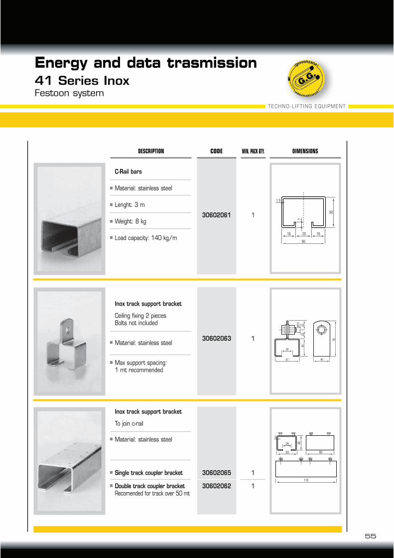
30602061 1
C-Rail bars
Material: stainless steel
Lenght: 3 m
Weight: 8 kg
Load capacity: 140 kg/m
130602063
Inox track support bracket
Ceiling fixing 2 piecesBolts not included
Material: stainless steel
Max support spacing:1 mt recommended
1
1
30602065
30602062
Inox track support bracket
To join c-rail
Material: stainless steel
Single track coupler bracket
Double track coupler bracketRecomended for track over 50 mt
90
61
28
40
44
23
23
M1
2
170
63 80
28
3
46
TECHNO-LIFT ING EQUIPMENT
Energy and data trasmission41 Series InoxFestoon system
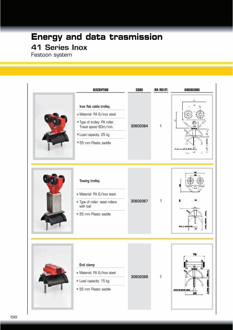
End clamp
Material: PA 6/Inox steel
Load capacity: 15 kg
55 mm Plastic saddle
56
Energy and data trasmission41 Series InoxFestoon system
30602066
1
CODE MIN. PACK QTY. DIMENSIONSDESCRIPTION
30602064
130602067
Inox flat cable trolley
Material: PA 6/inox steel
Type of trolley: PA roller.
Travel speed 60m/min.
Load capacity: 25 kg
55 mm Plastic saddle
Towing trolley
Material: PA 6/Inox steel
Type of roller: steel rollerswith ball
55 mm Plastic saddle
1
One roller trolley
Material: PA6 and galvanized steel
Type of roller: PA roller
Rotating 40 mm plastic saddle
Range 50 mm
57
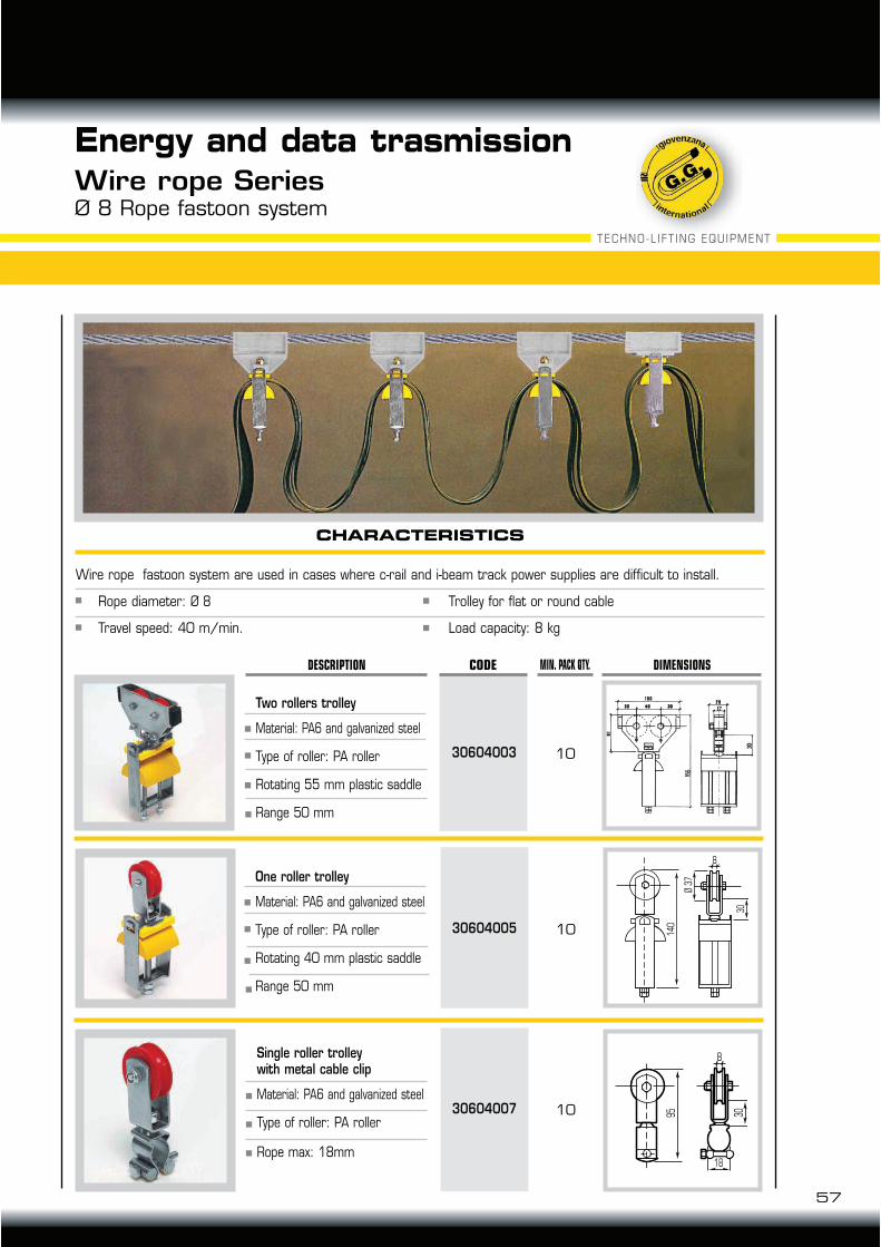
Energy and data trasmissionWire rope SeriesØ 8 Rope fastoon system
10
CODE MIN. PACK QTY. DIMENSIONSDESCRIPTION
30604003
Two rollers trolley
Material: PA6 and galvanized steel
Type of roller: PA roller
Rotating 55 mm plastic saddle
Range 50 mm
10 14
0
30
Ø 3
7
8
30604005
1030604007
Single roller trolleywith metal cable clip
Material: PA6 and galvanized steel
Type of roller: PA roller
Rope max: 18mm
30
95
8
18
CHARACTERISTICS
Wire rope fastoon system are used in cases where c-rail and i-beam track power supplies are difficult to install.
Rope diameter: Ø 8 Trolley for flat or round cable
Travel speed: 40 m/min. Load capacity: 8 kg
TECHNO-LIFT ING EQUIPMENT
85
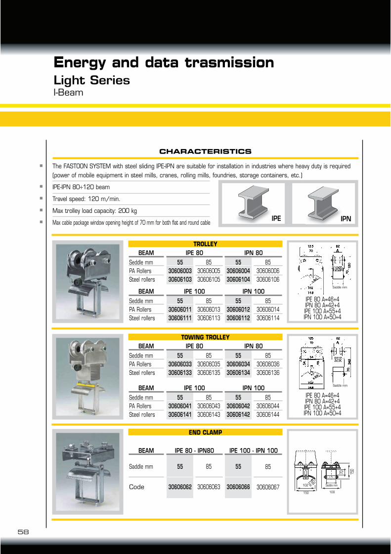
30606005
30606105
Seddle mm
PA Rollers
Steel rollers
BEAM IPE 80
150
70
150
102
A
100R 80
IPN 80
TROLLEY
55
30606003
30606103
85
30606006
30606106
55
30606004
30606104
85
30606013
30606113
Seddle mm
PA Rollers
Steel rollers
BEAM IPE 100 IPN 100
55
30606011
30606111
85
30606014
30606114
55
30606012
30606112
85
30606035
30606135
Seddle mm
PA Rollers
Steel rollers
BEAM IPE 80 IPN 80
TOWING TROLLEY
55
30606033
30606133
85
30606036
30606136
55
30606034
30606134
85
30606063
Saddle mm
Code
BEAM IPE 80 - IPN80 IPE 100 - IPN 100
END CLAMP
55
30606062
85
30606067
55
30606066
85
30606043
30606143
Seddle mm
PA Rollers
Steel rollers
BEAM IPE 100 IPN 100
55
30606041
30606141
85
30606044
30606144
55
30606042
30606142
IPE 80 A=46+4IPN 80 A=42+4IPE 100 A=55+4IPN 100 A=50+4
IPE 80 A=46+4IPN 80 A=42+4IPE 100 A=55+4IPN 100 A=50+4
Saddle mm
Saddle mm
The FASTOON SYSTEM with steel sliding IPE-IPN are suitable for installation in industries where heavy duty is required
(power of mobile equipment in steel mills, cranes, rolling mills, foundries, storage containers, etc.)
IPE-IPN 80÷120 beam
Travel speed: 120 m/min.
Max trolley load capacity: 200 kg
Max cable package window opening height of 70 mm for both flat and round cable
Energy and data trasmissionLight SeriesI-Beam
CHARACTERISTICS
IPNIPE
Saddle mm
100150
102
58
59
TECHNO-LIFT ING EQUIPMENT
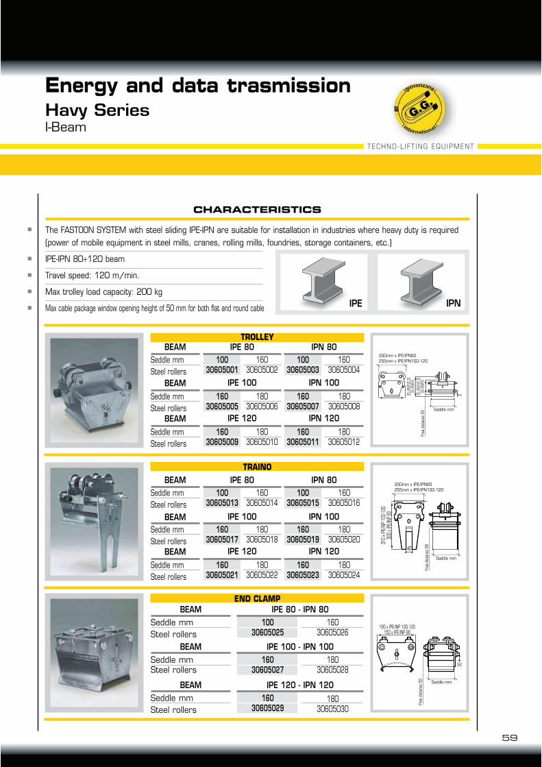
The FASTOON SYSTEM with steel sliding IPE-IPN are suitable for installation in industries where heavy duty is required
(power of mobile equipment in steel mills, cranes, rolling mills, foundries, storage containers, etc.)
IPE-IPN 80÷120 beam
Travel speed: 120 m/min.
Max trolley load capacity: 200 kg
Max cable package window opening height of 50 mm for both flat and round cable IPNIPE
Energy and data trasmissionHavy SeriesI-Beam
16030605002
Seddle mm
Steel rollers
BEAM IPE 80
190 x IPE/INP 100-120
150 x IPE/INP 80
30
CHARACTERISTICS
205 x
IPE/I
NP 10
0-120
300 x
IPE/I
NP 80
150 x
IPE/I
NP 10
0-120
300 x
IPE/I
NP 80
30
255 x IPE/INP 100-120
200 x IPE/INP 80
310
x IP
E/IN
P 10
0-12
0
300
x IP
E/IN
P 80
40
30
IPN 80TROLLEY
10030605001
16030605004
10030605003
18030605006
Seddle mm
Steel rollers
BEAM IPE 100 IPN 100
16030605005
18030605008
16030605007
18030605010
Seddle mm
Steel rollers
BEAM IPE 120 IPN 120
16030605009
18030605012
16030605011
16030605014
Seddle mm
Steel rollers
BEAM IPE 80 IPN 80
10030605013
16030605016
10030605015
18030605018
Seddle mm
Steel rollers
BEAM IPE 100 IPN 100
16030605017
18030605020
16030605019
18030605022
Seddle mm
Steel rollers
BEAM IPE 120 IPN 120
16030605021
18030605024
16030605023
TRAINO
16030605026
Seddle mm
Steel rollers
END CLAMP
BEAM IPE 80 - IPN 80
10030605025
18030605028
Seddle mmSteel rollers
BEAM IPE 100 - IPN 100
16030605027
18030605030
Seddle mm
Steel rollers
BEAM IPE 120 - IPN 120
16030605029
Saddle mm
200mm x IPE/IPN80
255mm x IPE/IPN100-120
Free
dis
tanc
e 50
Saddle mm
200mm x IPE/IPN80255mm x IPE/IPN100-120
Free
dis
tanc
e 59
Saddle mm
Free
dis
tanc
e 50
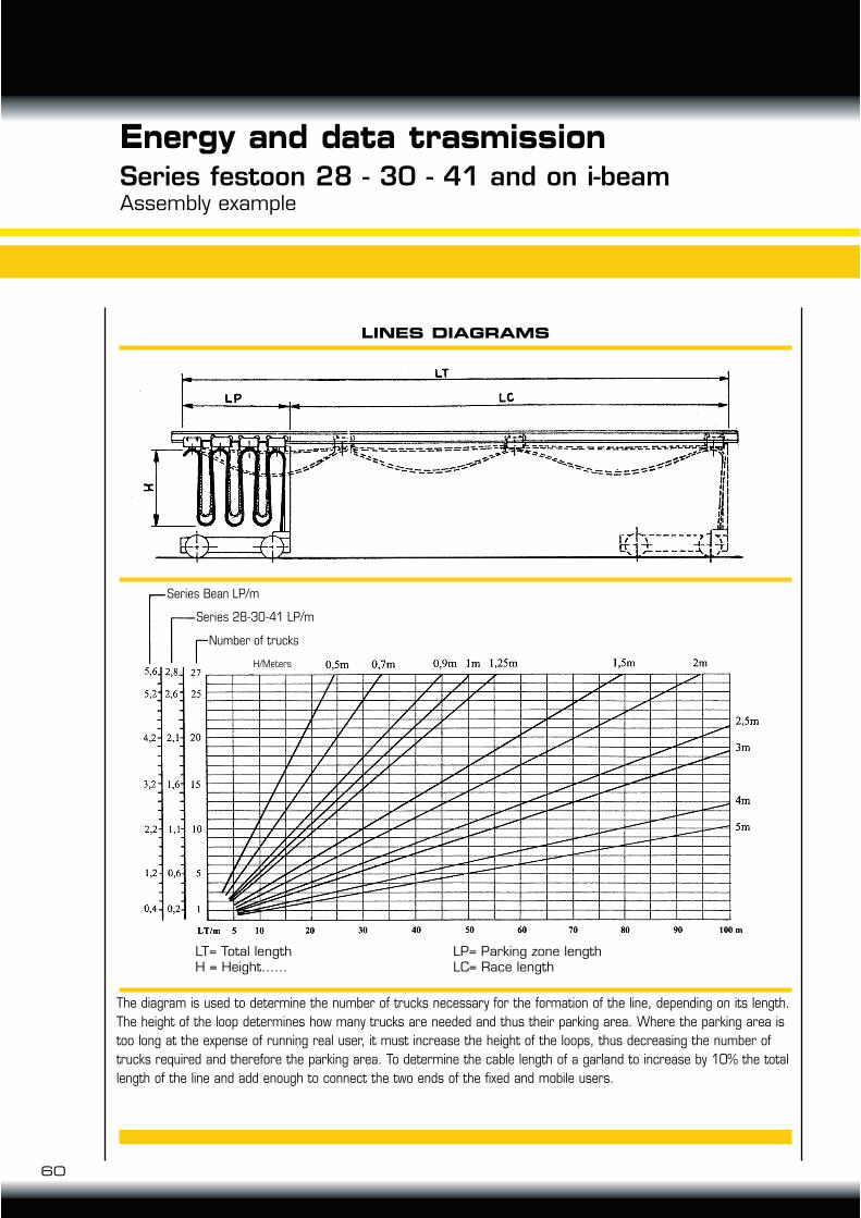
The diagram is used to determine the number of trucks necessary for the formation of the line, depending on its length.
The height of the loop determines how many trucks are needed and thus their parking area. Where the parking area is
too long at the expense of running real user, it must increase the height of the loops, thus decreasing the number of
trucks required and therefore the parking area. To determine the cable length of a garland to increase by 10% the total
length of the line and add enough to connect the two ends of the fixed and mobile users.
60
Energy and data trasmissionSeries festoon 28 - 30 - 41 and on i-beamAssembly example
LINES DIAGRAMS
LT= Total lengthH = Height……
LP= Parking zone lengthLC= Race length
Series Bean LP/m
Series 28-30-41 LP/m
Number of trucks
H/Meters
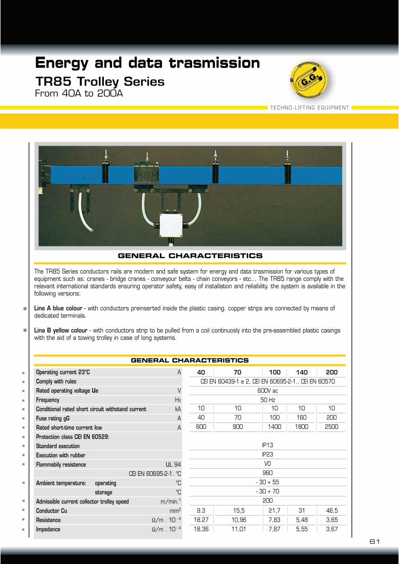
GENERAL CHARACTERISTICS
A
V
H2
kA
A
A
uL 94
CEI EN 60695-2-1. °C
°C
°C
m/min.1
mm2
/m . 10 - 4
/m . 10 - 4
Operating current 23°C
Comply with rules
Rated operating voltage ue
Frequency
Conditional rated short circuit withstand current
Fuse rating gG
Rated short-time current Icw
Protection class CEI EN 60529:
Standard execution
Execution with rubber
Flammabily resistence
Ambient temperature: operating
storage
Admissible current collector trolley speed
Conductor Cu
Resistence
Impedance
40
10
40
600
9.3
18,27
18,36
10
70
900
15,5
10,96
11,01
70
10
100
1400
21,7
7,83
7,87
10
160
1800
31
5,48
5,55
10
200
2500
46,5
3,65
3,67
100 140 200
CEI EN 60439-1 e 2, CEI EN 60695-2-1., CEI EN 60570
600V ac
50 Hz
IP13
IP23
VO
960
- 30 + 55
- 30 + 70
200
61
Energy and data trasmission
TR85 Trolley SeriesFrom 40A to 200A
GENERAL CHARACTERISTICS
The TR85 Series conductors rails are modern and safe system for energy and data trasmission for various types of equipment such as: cranes - bridge cranes - conveyour belts - chain conveyors - etc... The TR85 range comply with the relevant international standards ensuring operator safety, easy of installation and reliability. the system is available in the following versions:
Line A blue colour - with conductors preinserted inside the plastic casing. copper strips are connected by means of dedicated terminals.
Lina B yellow colour - with conductors strip to be pulled from a coil continuosly into the pre-assembled plastic casings with the aid of a towing trolley in case of long systems.
TECHNO-LIFT ING EQUIPMENT
L L
L/2
L/6 L/6
LL
L/2
L/10 L/10
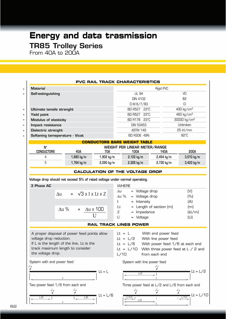
CALCULATION OF THE VOLTAGE DROP
RAIL TRACK LINES POWER
System with end power feed System with line power feed
Two power feed 1/6 from each end Three power feed at L/2 and L/6 from each end
Lt = L Lt = L/2
Material
Self-extinguishing
Ultimate tensile strenght
Yield point
Modulus of elasticity
Impact resistance
Dielectric strenght
Softening temeperature - Vicat
UL 94
DIN 4102
D.M.6/7/83
ISO R527 23°C
ISO R527 23°C
ISO R178 23°C
DIN 53453
ASTM 149
ISO R306 49N
Rigid PVC
Lt = L With end power feed
Lt = L/2 With line power feed
Lt = L/6 With power feed 1/6 at each end
Lt = L/10 With three power feed at L / 2 and
L/10 from each end
V0
B2
CI
430 kg/cm3
460 kg/cm2
30000 kg/cm2
Unbroken
25 kV/mm
82°C
4
5
N°CONDUCTORS
WEIGHT PER LINEAR METER/RANGE
CONDUCTORS BARS WEIGHT TABLE
1,680 kg/m
1,764 kg/m
1,902 kg/m
2,050 kg/m
40A
2,122 kg/m
2,305 kg/m
3,010 kg/m
3,423 kg/m
2,454 kg/m
2,730 kg/m
100A 200A70A 140A
3 Phase AC WHERE
u = Voltage drop (V)
u % = Voltage drop (%)
= Intensity (A)
!" = Length of section (m) (m)
# = Impedance ( /m)
$ = Voltage (U)
u = !3 x x !" x #
u % = u x 100
$
A proper disposal of power feed points allow
voltage drop reduction.
If L is the length of the line, Lt is the
track maximum length to consider
the voltage drop.
Voltage drop should not exceed 5% of rated voltage under normal operating.
PVC RAIL TRACK CHARACTERISTICS
Lt = L/6 Lt = L/10
62
Energy and data trasmissionTR85 Trolley SeriesFrom 40A to 200A
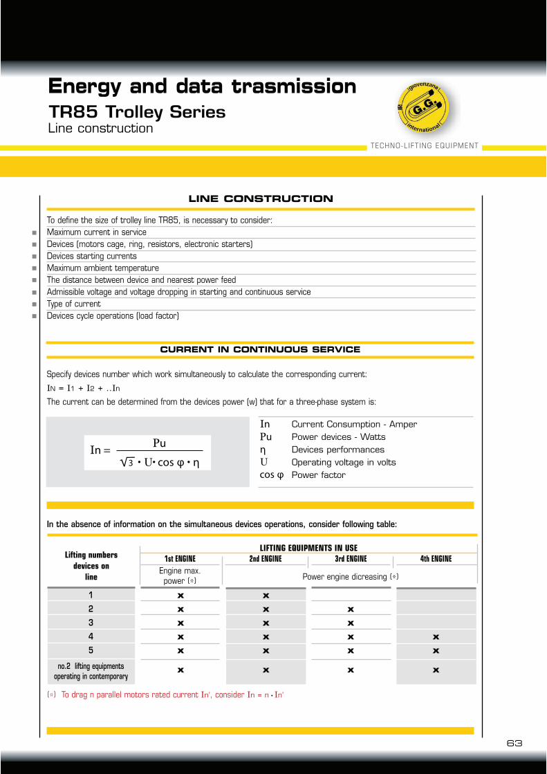
63
TECHNO-LIFT ING EQUIPMENT
CURRENT IN CONTINUOUS SERVICE
Energy and data trasmission
TR85 Trolley SeriesLine construction
LINE CONSTRUCTION
To define the size of trolley line TR85, is necessary to consider:
Maximum current in service
Devices (motors cage, ring, resistors, electronic starters)
Devices starting currents
Maximum ambient temperature
The distance between device and nearest power feed
Admissible voltage and voltage dropping in starting and continuous service
Type of current
Devices cycle operations (load factor)
Specify devices number which work simultaneously to calculate the corresponding current:
N = 1 + 2 + .. n
The current can be determined from the devices power (w) that for a three-phase system is:
In the absence of information on the simultaneous devices operations, consider following table:
(*) To drag n parallel motors rated current n’, consider n = n n’
Current Consumption - Amper
Power devices - Watts
Devices performances
Operating voltage in volts
Power factor
n =!u
φ cos η3
n
!u
φcos
η
LIFTING EQUIPMENTS IN USELifting numbers
devices on
line
1
2
3
4
5
no.2 lifting equipmentsoperating in contemporary
Engine max.power (*)
1st ENGINE
Power engine dicreasing (*)
4th ENGINE3rd ENGINE2nd ENGINE
x
x
x
x
x
x
x
x
x
x
x
x
x
x
x
x
x
x
x
x
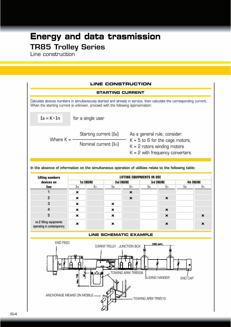
STARTING CURRENT
LINE SCHEMATIC EXAMPLE
Line construction
LINE CONSTRUCTION
Calculate devices numbers in simultaneously started and already in service, then calculate the corresponding current. When the starting current is unknown, proceed with the following approximation:
In the absence of information on the simultaneous operation of utilities relate to the following table:
for a single user
Where K =Starting current ( a)
Nominal current ( n)
As a general rule, consider:
K = 5 to 6 for the cage motors,
K = 2 rotors winding motors
K = 2 with frequency converters
64
Energy and data trasmissionTR85 Trolley Series
a = K n
LIFTING EQUIPMENTS IN USELifting numbers
devices on
line
1
2
3
4
5
no.2 lifting equipmentsoperating in contemporary
n a
1st ENGINE n a
4th ENGINE n a
3rd ENGINE n a
2nd ENGINE
x
x
x
x
x
x
x
x
x
x
x
x
x
x
x
x
x
x
END FEED
TOWING ARM TR8510
END CAPSLIDING HANGER
TOWING ARM TR8508
ANCHORAGE MEANS ON MOBILE
CURRENT TROLLEY JUNCTION BOX
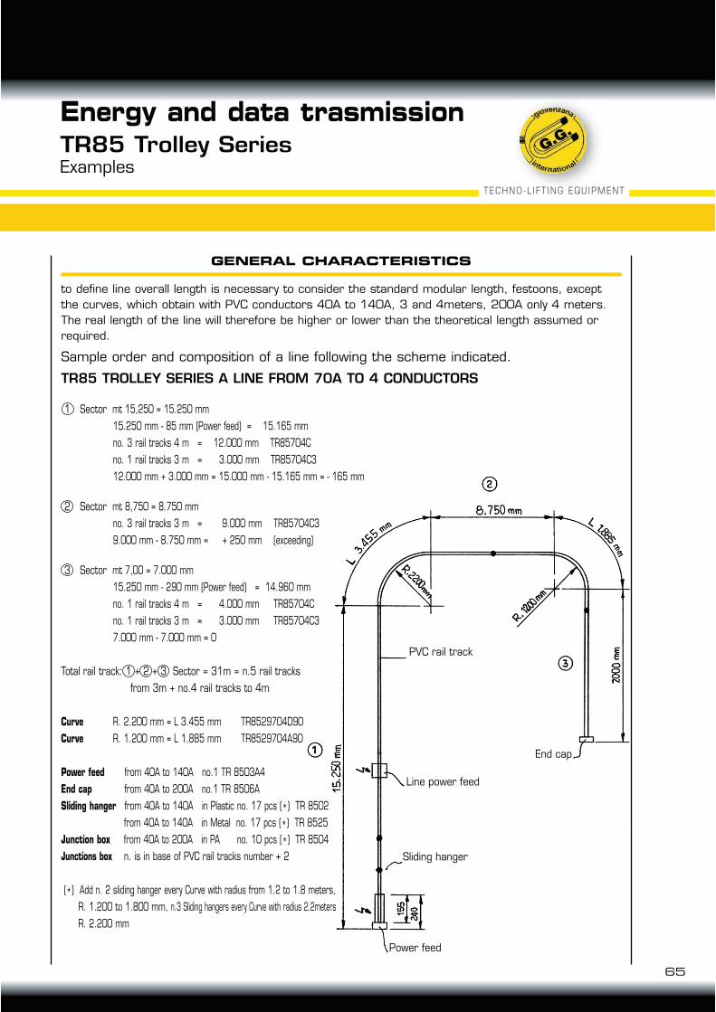
65
Energy and data trasmissionTR85 Trolley SeriesExamples
GENERAL CHARACTERISTICS
to define line overall length is necessary to consider the standard modular length, festoons, except
the curves, which obtain with PVC conductors 40A to 140A, 3 and 4meters, 200A only 4 meters.
The real length of the line will therefore be higher or lower than the theoretical length assumed or
required.
Sample order and composition of a line following the scheme indicated.
TR85 TROLLEY SERIES A LINE FROM 70A TO 4 CONDUCTORS
1 Sector mt 15,250 = 15.250 mm
15.250 mm - 85 mm (Power feed) = 15.165 mm
no. 3 rail tracks 4 m = 12.000 mm TR85704C
no. 1 rail tracks 3 m = 3.000 mm TR85704C3
12.000 mm + 3.000 mm = 15.000 mm - 15.165 mm = - 165 mm
2 Sector mt 8,750 = 8.750 mm
no. 3 rail tracks 3 m = 9.000 mm TR85704C3
9.000 mm - 8.750 mm = + 250 mm (exceeding)
3 Sector mt 7,00 = 7.000 mm
15.250 mm - 290 mm (Power feed) = 14.960 mm
no. 1 rail tracks 4 m = 4.000 mm TR85704C
no. 1 rail tracks 3 m = 3.000 mm TR85704C3
7.000 mm - 7.000 mm = 0
Total rail track: 1 + 2 + 3 Sector = 31m = n.5 rail tracks
from 3m + no.4 rail tracks to 4m
Curve R. 2.200 mm = L 3.455 mm TR8529704D90
Curve R. 1.200 mm = L 1.885 mm TR8529704A90
Power feed from 40A to 140A no.1 TR 8503A4
End cap from 40A to 200A no.1 TR 8506A
Sliding hanger from 40A to 140A in Plastic no. 17 pcs (*) TR 8502
from 40A to 140A in Metal no. 17 pcs (*) TR 8525
Junction box from 40A to 200A in PA no. 10 pcs (*) TR 8504
Junctions box n. is in base of PVC rail tracks number + 2
(*) Add n. 2 sliding hanger every Curve with radius from 1.2 to 1.8 meters,
R. 1.200 to 1.800 mm, n.3 Sliding hangers every Curve with radius 2.2meters
R. 2.200 mm
TECHNO-LIFT ING EQUIPMENT
Line power feed
PVC rail track
Sliding hanger
End cap
Power feed

REACH
CLOSING
POWER
3
4
Energy and data trasmissionTR85 Trolley SeriesConductor rails - Line A “plug-in” type
L INMETERS
N°CONDUCTORS
REACH
BAR INSULATING INTERMEDIATE 200A
454
5
TR85704C3TR85705C3TR85704C
TR85705C
TR85404C3TR85405C3TR85404C
TR85405C
40A 70A
3
4
3
4
L INMETERS
L INMETERS
N°CONDUCTORS
N°CONDUCTORS
REACH
REACH
4545
4545
TR851404C3TR851405C3TR851404CTR851405C
TR851004C3TR851005C3TR851004CTR851005C
100A
TR852004C3TR852005C3TR852004CTR852005C
200A
140A
200
L INmm
N°CONDUCTORS
REACH
4
5
TR8503A4
TR8503A5
TR8533A4
TR8533A5
40A....140A
200A
200
L INmm
N°CONDUCTORS
4
5
TR8506A 1
MIN. PACK QTY.CODE
Standard length 200 mm
Standard length 100 mm
Closed neutral Rails
at 4 and 5 Conductors
from 40A to 200A
CONDUCTOR RAIL INSULATING INTERMEDIATE 40A - 70A - 100A - 140A
66
40A......140A Series
200A Series
L
L
85
56
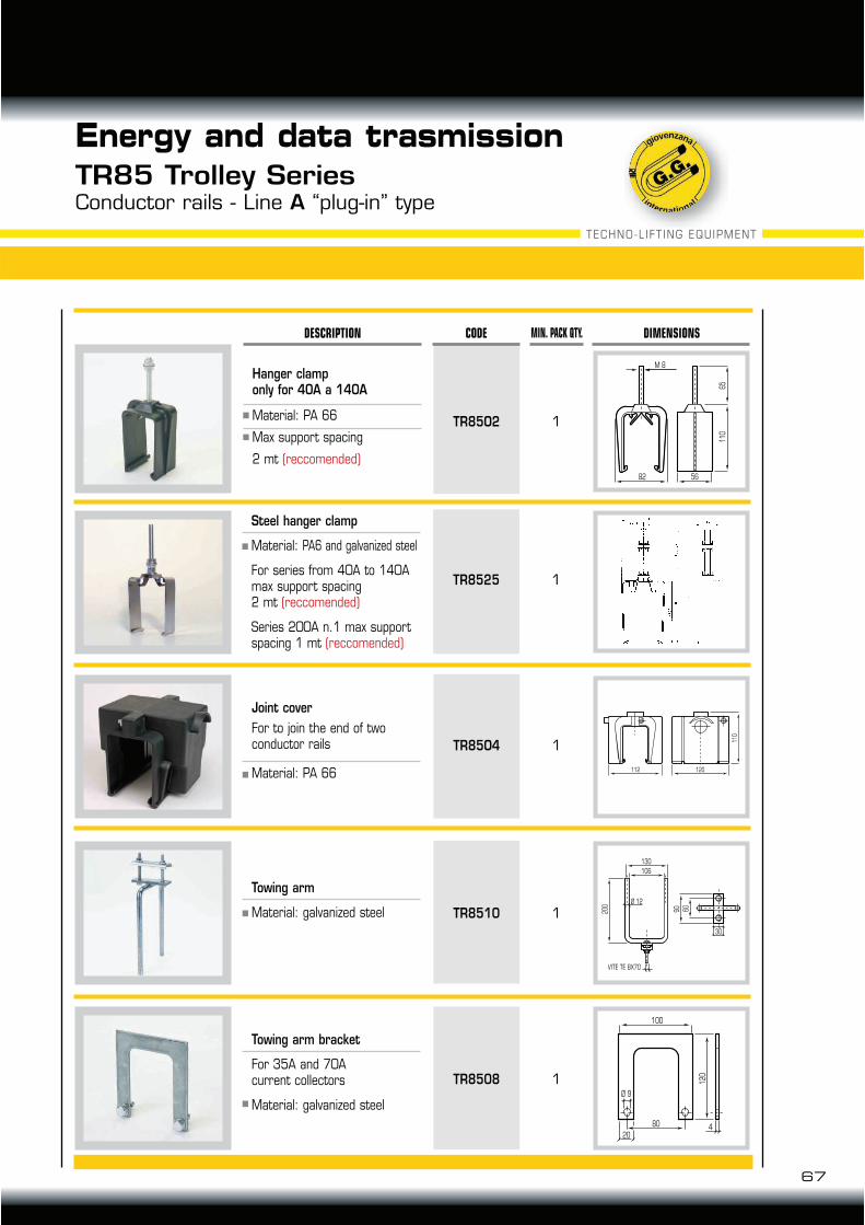
Steel hanger clamp
Material: PA6 and galvanized steel
For series from 40A to 140Amax support spacing2 mt (reccomended)
Series 200A n.1 max support spacing 1 mt (reccomended)
1TR8525
112 120
11
0
Joint cover
For to join the end of twoconductor rails
Material: PA 66
1TR85O4
1
82
11
06
5
56
M 8
CODE MIN. PACK QTY. DIMENSIONSDESCRIPTION
TR85O2
Towing arm
Material: galvanized steel 90 60
30
VITE TE 8X70
20
0
130
106
Ø 12
120
100
80
204
Ø 9
1TR8510
Towing arm bracket
For 35A and 70Acurrent collectors
Material: galvanized steel
1TR8508
Hanger clamponly for 40A a 140A
Material: PA 66
Max support spacing
2 mt (reccomended)
67
Energy and data trasmissionTR85 Trolley SeriesConductor rails - Line A “plug-in” type
TECHNO-LIFT ING EQUIPMENT
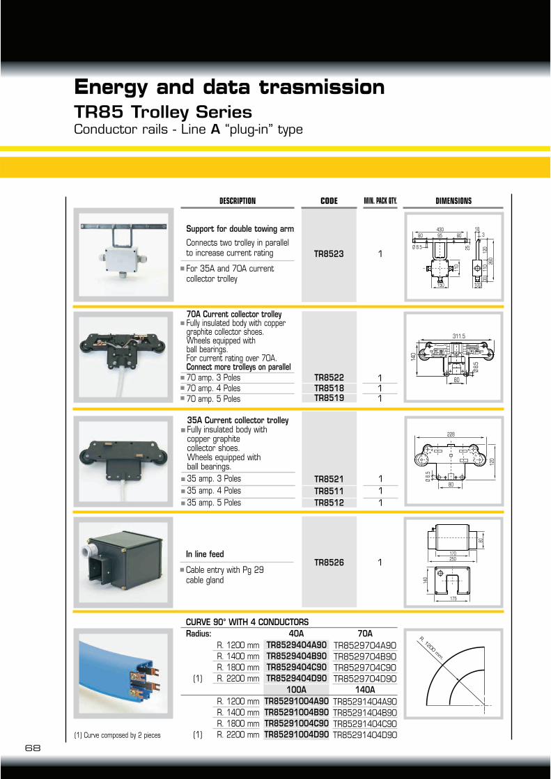
311.5
140
80
Ø 8
.5
Support for double towing arm
Connects two trolley in parallel to increase current rating
For 35A and 70A currentcollector trolley
430
26
0
11
0
150 100
12
01
10
30
Ø 8.5
18
380 8095
25
1TR8523
228
80
120
Ø 8
.5
TR8521
TR8511
TR8512
1
1
1
35A Current collector trolleyFully insulated body withcopper graphitecollector shoes.Wheels equipped withball bearings.
35 amp. 3 Poles
35 amp. 4 Poles
35 amp. 5 Poles
TR8522TR8518TR8519
111
70A Current collector trolleyFully insulated body with copper graphite collector shoes.Wheels equipped withball bearings.For current rating over 70A.Connect more trolleys on parallel 70 amp. 3 Poles70 amp. 4 Poles70 amp. 5 Poles
68
Energy and data trasmissionTR85 Trolley SeriesConductor rails - Line A “plug-in” type
CODE MIN. PACK QTY. DIMENSIONSDESCRIPTION
In line feed
Cable entry with Pg 29cable gland
CURVE 90° WITH 4 CONDUCTORS
Radius: 40A
100A
70A
140A
175
170
80
140
250
R. 1
200 m
m.
1TR8526
TR8529404A90
TR8529404B90
TR8529404C90
TR8529404D90
TR85291004A90
TR85291004B90
TR85291004C90
TR85291004D90
TR8529704A90
TR8529704B90
TR8529704C90
TR8529704D90
TR85291404A90
TR85291404B90
TR85291404C90
TR85291404D90
R. 1200 mm
R. 1400 mm
R. 1800 mm
(1) R. 2200 mm
R. 1200 mm
R. 1400 mm
R. 1800 mm
(1) R. 2200 mm(1) Curve composed by 2 pieces

69
Energy and data trasmissionTR85 Trolley SeriesConductor rails - Line B “continuos strip” type
L
End cap
To close the endsof the line
Material: PA 66
Cable entry with M40cable gland
Material: PA 66
1TR8506
TR8503 1
End feed
4
L INMETERS
N°CONDUCTORS
REACH
4
5
TR851004
TR851005
TR851404
TR851405
TR85704
TR85705
70A 100A 140A
Conductors are supplied separately. The copper strip is pulled from a coil into the plastic casing with the aid of the TR8513 de-coil unit end TR8514 strip insertion trolley available Series to 140A
CODE MIN. PACK QTY. DIMENSIONSDESCRIPTION
PVC RAIL TRACK
Standard length: 4mt
85
56
TECHNO-LIFT ING EQUIPMENT
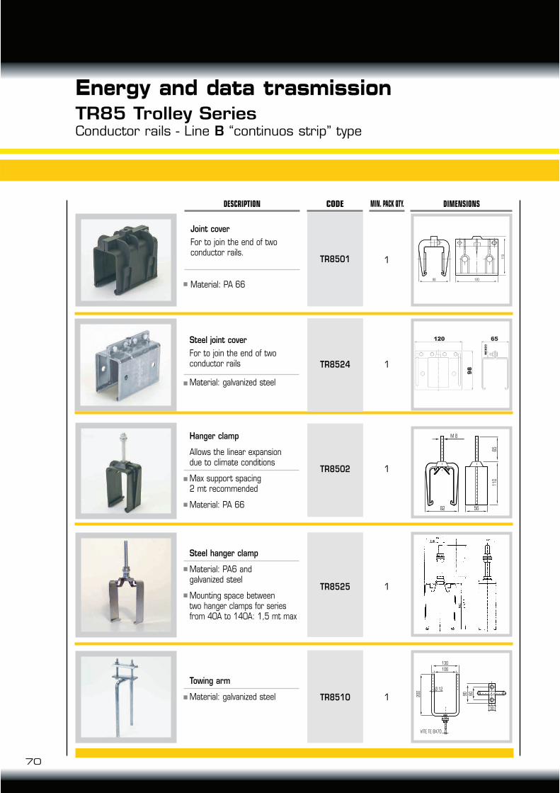
Towing arm
Material: galvanized steel 90 60
30
VITE TE 8X70
20
0
130
106
Ø 12
1TR8510
110
88 120
1TR8501
Joint cover
For to join the end of twoconductor rails.
Material: PA 66
70
Energy and data trasmissionTR85 Trolley SeriesConductor rails - Line B “continuos strip” type
82
11
06
5
56
M 8
CODE MIN. PACK QTY. DIMENSIONSDESCRIPTION
Steel hanger clamp
Material: PA6 andgalvanized steel
Mounting space betweentwo hanger clamps for series from 40A to 140A: 1,5 mt max
Steel joint cover
For to join the end of twoconductor rails
Material: galvanized steel
Hanger clamp
Allows the linear expansiondue to climate conditions
Max support spacing2 mt recommended
Material: PA 66
1TR8524
1TR8502
1TR8525
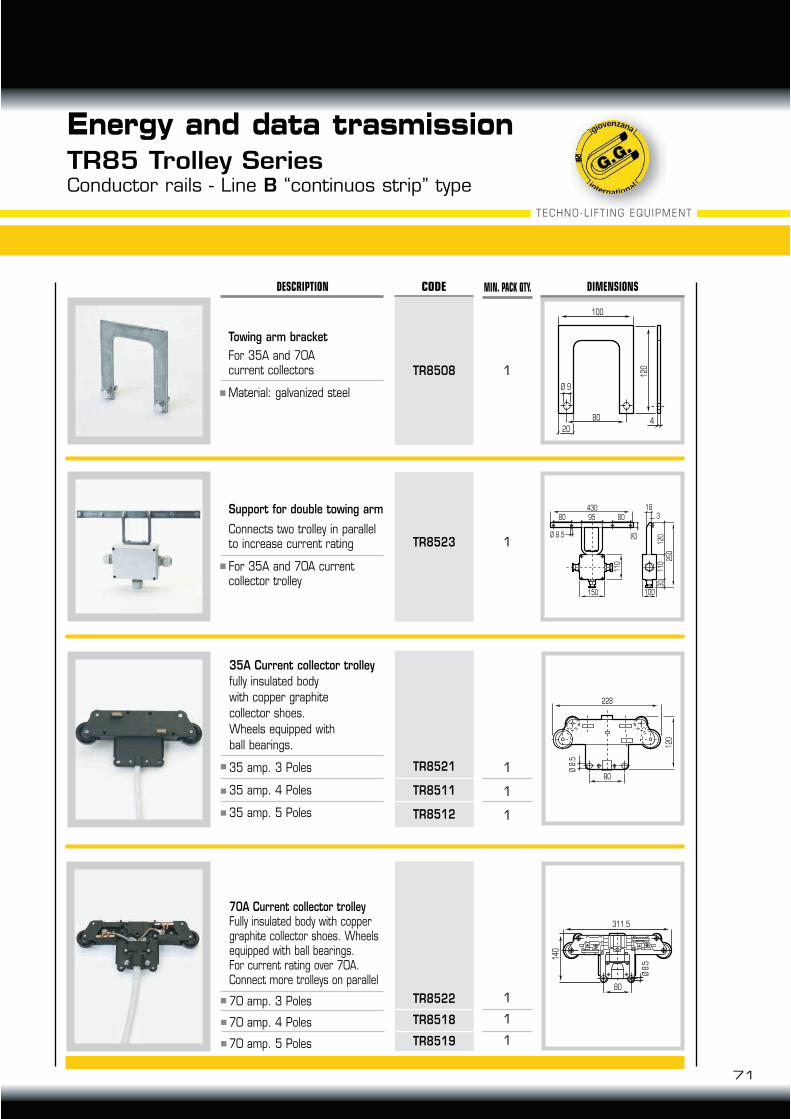
71
Energy and data trasmissionTR85 Trolley SeriesConductor rails - Line B “continuos strip” type
CODE MIN. PACK QTY. DIMENSIONSDESCRIPTION
120
100
80
204
Ø 9
430
260
110
150 100
120
110
30
Ø 8.5
18
380 8095
25
1TR8508
Towing arm bracket
For 35A and 70Acurrent collectors
Material: galvanized steel
1TR8523
Support for double towing arm
Connects two trolley in parallel to increase current rating
For 35A and 70A currentcollector trolley
228
80
12
0
Ø 8
.5
311.5
140
80
Ø 8
.5
35A Current collector trolley
fully insulated body
with copper graphite
collector shoes.
Wheels equipped with
ball bearings.
35 amp. 3 Poles
35 amp. 4 Poles
35 amp. 5 Poles
TR8521
TR8511
TR8512
1
1
1
TR8522
TR8518
TR8519
1
1
1
70A Current collector trolleyFully insulated body with copper graphite collector shoes. Wheels equipped with ball bearings.For current rating over 70A.Connect more trolleys on parallel
70 amp. 3 Poles
70 amp. 4 Poles
70 amp. 5 Poles
TECHNO-LIFT ING EQUIPMENT
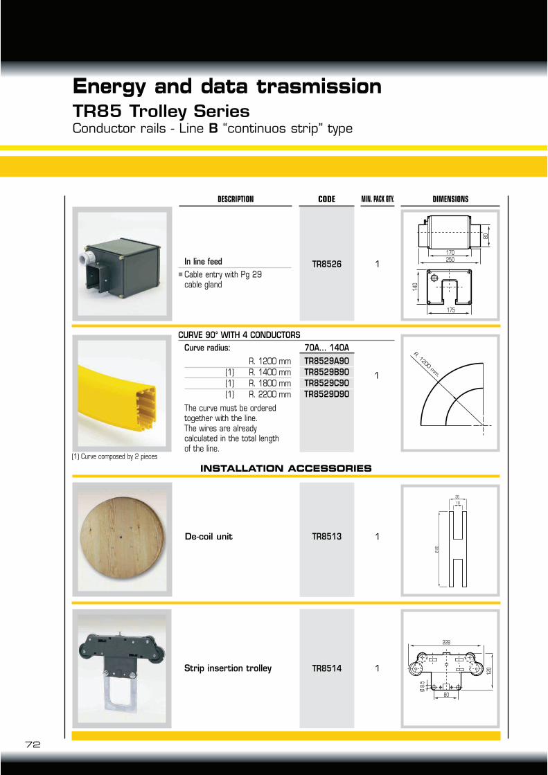
72
Energy and data trasmissionTR85 Trolley SeriesConductor rails - Line B “continuos strip” type
CODE MIN. PACK QTY. DIMENSIONSDESCRIPTION
Ø 8
0
36
18
228
80
12
0
Ø 8
.5
De-coil unit TR8513 1
TR8514 1Strip insertion trolley
In line feed
Cable entry with Pg 29cable gland
175
170
80
140
250
R. 1
200 m
m.
1TR8526
1
CURVE 90° WITH 4 CONDUCTORS
Curve radius:
The curve must be ordered together with the line.The wires are alreadycalculated in the total lengthof the line.
70A... 140A
TR8529A90
TR8529B90
TR8529C90
TR8529D90
R. 1200 mm
(1) R. 1400 mm
(1) R. 1800 mm
(1) R. 2200 mm
INSTALLATION ACCESSORIES
(1) Curve composed by 2 pieces
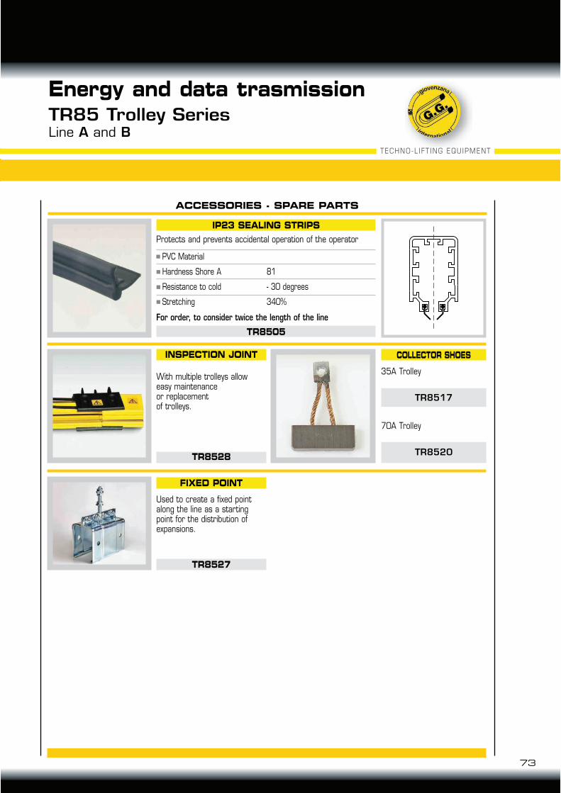
TECHNO-LIFT ING EQUIPMENT
73
Energy and data trasmissionTR85 Trolley SeriesLine A and B
IP23 SEALING STRIPS
TR8505
COLLECTOR SHOES
FIXED POINT
TR8527
Protects and prevents accidental operation of the operator
For order, to consider twice the length of the line
ACCESSORIES - SPARE PARTS
INSPECTION JOINT
TR8528
With multiple trolleys alloweasy maintenanceor replacementof trolleys.
Used to create a fixed point along the line as a starting point for the distribution of expansions.
70A Trolley
TR8520
35A Trolley
TR8517
PVC Material
Hardness Shore A 81
Resistance to cold - 30 degrees
Stretching 340%
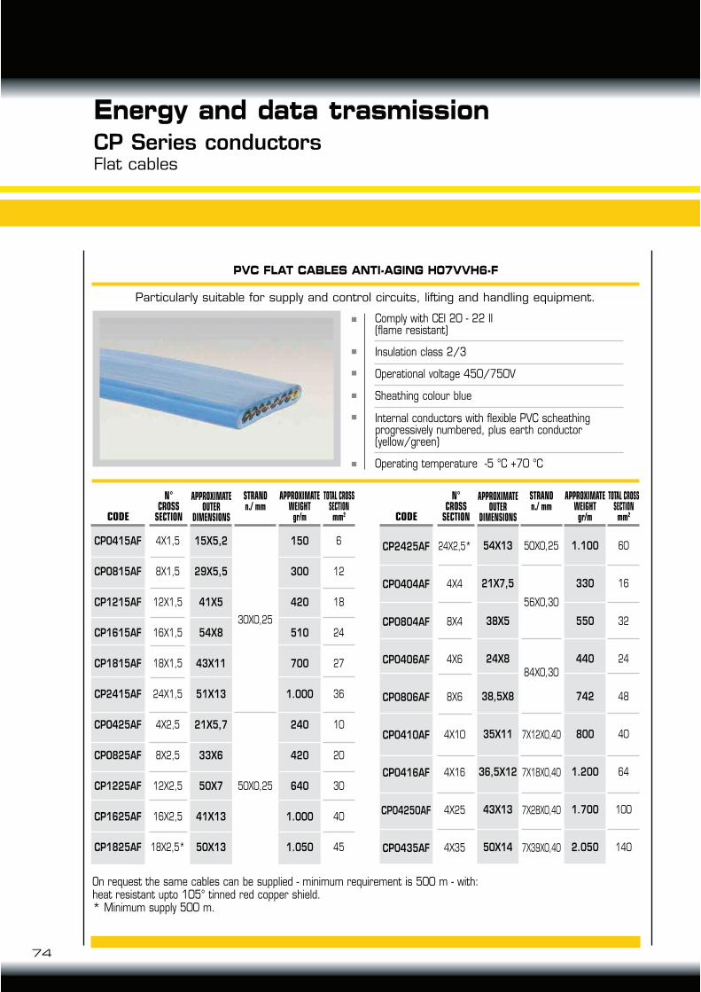
Energy and data trasmissionCP Series conductorsFlat cables
74
Particularly suitable for supply and control circuits, lifting and handling equipment.
PVC FLAT CABLES ANTI-AGING H07VVH6-F
Comply with CEI 20 - 22 II(flame resistant)
Insulation class 2/3
Operational voltage 450/750V
Sheathing colour blue
Internal conductors with flexible PVC scheathingprogressively numbered, plus earth conductor(yellow/green)
Operating temperature -5 °C +70 °C
CODE
6
12
18
24
27
36
10
20
30
40
45
30X0,25
50X0,25
APPROXIMATE OUTER
DIMENSIONS
N°CROSS
SECTION
CPO415AF
CPO815AF
CP1215AF
CP1615AF
CP1815AF
CP2415AF
CPO425AF
CPO825AF
CP1225AF
CP1625AF
CP1825AF
15X5,2
29X5,5
41X5
54X8
43X11
51X13
21X5,7
33X6
50X7
41X13
50X13
150
300
420
510
700
1.000
240
420
640
1.000
1.050
APPROXIMATE WEIGHT
gr/m
STRAND n./ mm
TOTAL CROSS SECTION mm2 CODE
60
16
32
24
48
40
64
100
140
56X0,30
84X0,30
7X12X0,40
7X18X0,40
7X28X0,40
7X39X0,40
50X0,25
APPROXIMATE OUTER
DIMENSIONS
N°CROSS
SECTION
CP2425AF
CP0404AF
CP0804AF
CP0406AF
CP0806AF
CP0410AF
CP0416AF
CP04250AF
CP0435AF
54X13
21X7,5
38X5
24X8
38,5X8
35X11
36,5X12
43X13
50X14
1.100
330
550
440
742
800
1.200
1.700
2.050
APPROXIMATE WEIGHTgr/m
STRAND n./ mm
On request the same cables can be supplied - minimum requirement is 500 m - with:heat resistant upto 105° tinned red copper shield.* Minimum supply 500 m.
TOTAL CROSS SECTION mm2
4X1,5
8X1,5
12X1,5
16X1,5
18X1,5
24X1,5
4X2,5
8X2,5
12X2,5
16X2,5
18X2,5*
24X2,5*
4X4
8X4
4X6
8X6
4X10
4X16
4X25
4X35
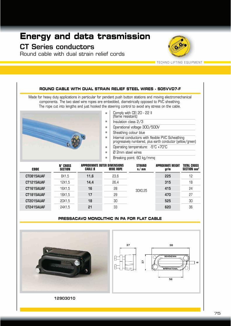
75
Energy and data trasmissionCT Series conductorsRound cable with dual strain relief cords
PRESSACAVO MONOLITHIC IN PA FOR FLAT CABLE
Made for heavy duty applications in particular for pendant push button stations and moving electromechanicalcomponents. The two steel wire ropes are embedded, diametrically opposed to PVC sheathing.The rope cut into lengths and just hooked the steering control to avoid any stress on the cable.
ROUND CABLE WITH DUAL STRAIN RELIEF STEEL WIRES - S05VVD7-F
Comply with CEI 20 - 22 II(flame resistant)
Insulation class 2/3
Operational voltage 300/500V
Sheathing colour blue
Internal conductors with flexible PVC Scheathingprogressively numbered, plus earth conductor (yellow/green)
Operating temperature: -5°C +70°C
Ø 2mm steel wires
Breaking point: 60 kg/mmq
CODE
8X1,5
12X1,5
16X1,5
18X1,5
20X1,5
24X1,5
12
18
24
27
30
36
APPROXIMATE OUTER DIMENSIONSN° CROSS SECTION
CT0815AUAF
CT1215AUAF
CT1615AUAF
CT1815AUAF
CT2015AUAF
CT2415AUAF
11,6
14,4
16
17
18
21
225
315
415
470
525
620
APPROXIMATE WEIGHTgr/m
23,6
26,4
28
29
30
33
STRANDn./ mm
30X0,25
TOTAL CROSS SECTION mm2CABLE Ø WIRE ROPE
12903010
TECHNO-LIFT ING EQUIPMENT
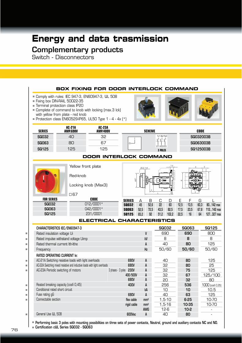
76
Complementary productsSwitch - Disconnectors
Energy and data trasmission
BOX FIXING FOR DOOR INTERLOCK COMMAND
DOOR INTERLOCK COMMAND
Comply with rules: IEC 947-3, EN60947-3, uL 508Fixing box DIN-RAIL 50022-35Terminal protection class IP20Complete of command to knob with locking (max.3 Ick)with yellow from plate - red knobProtection class EN60529-IP65, UL50 Type 1 - 4 - 4x (*)
Performing basic 3 poles with mounting possibilities on three sets of power contacts, Neutral, ground and auxiliary contacts NC and NO.Certification cuL Series SQ032 - SQ063
ELECTRICAL CHARACTERISTICS
RATED OPERATING CURRENT Ie:
AC-21A Switching resistive loads with light overloads
AC-22A Switching mixed resistive and inductive loads with light overloads
AC-23A Periodic switching of motors
40
32
32
32
20
256
10
40
1,5-10
1,5-16
12-6
40
125
25
125
125/100
80
1000 (cosfi 0,35)
10,5
125
10-70
10-70
-
-
CHARACTERISTICS IEC/EN60947-3
Rated insulation voltage Ui
Rated impulse withstand voltage Uimp
Rated thermal current Ith-Ithe
Frequency
SQ032
690
8
40
50/60
SQ063
690
8
80
50/60
SQ125
800
8
125
50/60
V
kV
A
Hz
A
A
A
AA
690V
690V
230V
400/500V690V
3 phases - 3 poles
A
kA
A
mm2
mm2
AWG
A
400V
690V
flex cable
rigid cable
600Vac
80
80
75
67
32
536
10
63
6-25
10-35
10-2
80
A E
C
B D
GF
L
1+4
7,3
5
67
30,2Yellow front plate
Red-knob
Locking knob (Max3)
67
SQ032
SQ063
SQ125
FOR SERIES CODE
012/0001*
042/0001*
231/0001
32
67
125
SQ032
SQ063
SQ125
SERIESAC-21A
AMP.690V
40
80
125
AC-23AAMP.400V SCHEME CODE
SQ032003B
SQ063003B
SQ125003B
0
I
1 L1 3L2 5L3
2T14T2 6T3
3 POLES
13,523,516
A B C D E GF80...142 max
112...142 max127...327 max
L45
52,565,2
SERIESSQ032SQ063SQ125
52,672,592
2243,551,2
6082,5
102,2
12,517,522,5
60,367,864
Reated breaking capacity (cosfi 0,45)
Conditional rated short circuit
Fuse rating gG
Connectable section
General Use uL 508

78
Annotations
GIOVENZANAINTERNATIONAL B.V.

TECHNO-LIFT ING EQUIPMENT
79
Annotations
GIOVENZANAINTERNATIONAL B.V.
