mechanisms in impact fragmentation
TRANSCRIPT

Int J Fract (2008) 154:105–117DOI 10.1007/s10704-008-9267-6
ORIGINAL PAPER
Mechanisms in impact fragmentation
F. K. Wittel · H. A. Carmona · F. Kun ·H. J. Herrmann
Received: 15 April 2008 / Accepted: 7 October 2008© Springer Science+Business Media B.V. 2008
Abstract The brittle fragmentation of spheres is stu-died numerically by a 3D Discrete Element Model.Large scale computer simulations are performed withmodels that consist of agglomerates of many spheri-cal particles, interconnected by beam-truss elements.We focus on a detailed description of the fragmenta-tion process and study several fragmentation mecha-nisms involved. The evolution of meridional cracks isstudied in detail. These cracks are found to initiate inthe inside of the specimen with quasi-periodic angu-lar distribution and give a broad peak in the fragmentmass distribution for large fragments that can be fittedby a two-parameter Weibull distribution. The resultsprove to be independent of the degree of disorder in themodel, but mean fragment sizes scale with velocity.Our results reproduce many experimental observationsof fragment shapes, impact energy dependence or massdistribution, and significantly improve the understan-ding of the fragmentation process for impact fracture
F. K. Wittel (B) · H. J. HerrmannComputational Physics for Engineering Materials IfB, ETHZurich, Schafmattstr. 6, HIF, 8093 Zurich, Switzerlande-mail: [email protected]: http://comphys.ethz.ch
H. A. CarmonaCentro de Ciências e Tecnologia, Universidade Estadual doCeará, 60740-903 Fortaleza, Ceara, Brazil
F. KunDepartment of Theoretical Physics, Universityof Debrecen, P.O. Box 5, 4010 Debrecen, Hungary
since we have full access to the failure conditions andevolution.
Keywords Fragmentation · Computer simulation ·Discrete element method · Comminution
1 Introduction
Fragmentation is ubiquitous in nature and can be foundon all scales. Technologically we make strong use offragmentation for example in industrial comminutionprocesses where the focus lies on the specific reductionof material to preferred sizes, minimizing the necessaryenergy and amount of nano-toxic powder production.Therefore, predicting the resulting fragment mass dis-tributions, understanding the underlying fragmentationmechanisms and scaling relations is an important fieldof research that has attracted the attention of resear-chers over the last decades. Fragmentation of singlebrittle spheres has been studied experimentally andnumerically to understand the elementary fragmenta-tion processes that govern comminution. Experimentsfrom the 60 s analyzed the fragment mass and size dis-tributions (Arbiter et al. 1969; Gilvarry and Bergstrom1961; Gilvarry and Bergstrom 1962) with the strikingobservation, that the mass distribution in the range ofsmall fragments follows a power law with exponentsthat are universal with respect to material or the wayenergy is imparted to the system. Later it was foundthat the exponents depend on the dimensionality of the
123

106 F. K. Wittel et al.
object (Turcotte 1986). These findings were confirmedby numerical simulations, mainly based on DiscreteElement Models (DEM) (Åström et al. 2000; Diehl et al.2000; Kun and Herrmann 1996a,b). For large frag-ment masses, deviation from the power-law distribu-tion could be modelled by an exponential cut-off, andby using a bi-linear or Weibull distribution (Antonyuket al. 2006; Potapov and Campbell 1996; Cheong et al.2004; Lu et al. 2002; Meibom and Balslev 1996; Odder-shede 1993). It is an every day experience that frag-mentation is only obtained above a certain materialdependent energy input. Numerical simulation couldprove a phase transition at a critical energy with thefragmentation regime above and the fracture or dama-ged regime below a critical point (Behera et al. 2005;Kun and Herrmann 1999; Thornton et al. 1999). Thefragmentation process itself became accessible with theavailability of high speed cameras (Andrews and Kim1998, 1999; Antonyuk et al. 2006; Chau et al. 2000;Majzoub and Chaudhri 2000; Salman et al. 2002; Schu-bert et al. 2005; Tomas et al 1999; Wu et al. 2004). Belowthe critical point only slight damage could be obser-ved, while above the specimen breaks into a smallnumber of fragments of the shape of wedges, formedby meridional fracture planes, and additional cone-shaped fragments at the specimen-target contact point.By meridional we mean along a meridian, or otherwords from south to north or small to large z values.Way above the critical point, oblique fracture planesdevelop, that further fragment the wedge shaped frag-ments.
Today the mechanisms involved in the initiation andpropagation of single cracks are fairly well understood,and statistical models have been successfully appliedto describe macroscopic fragmentation (Åström 2006;Herrmann and Roux 1990). However, when it comes tocomplex fragmentation processes with instable dyna-mic growth of many competing cracks in the three-dimensional space (3D), much less is understood.Today model sizes become possible that allow for 3Dsimulations with many thousand particles and interac-tion forces that are more realistic than simple centralpotentials. These give a good refined insight of what isreally happening inside the system, and how the pre-dicted outcome of the fragmentation process dependson system properties. Numerical simulations can reco-ver some of these findings, but while 2D models areincapable of reproducing the meridional fracture planes(Behera et al. 2005; Khanal et al. 2004; Kun and Herr-
mann 1999; Potapov et al. 1995; Potapov and Campbell1997; Thornton et al. 1996), 3D simulations were res-tricted to relatively small systems, and could not studythe mechanisms that initiate and drive meridional frac-ture planes (Potapov and Campbell 1996; Thorntonet al. 1999). (Arbiter et al. 1969) argued, based on highspeed photographs that fracture initiates from the per-iphery of the contact disc between the specimen andthe plane, due to the circumferential tension inducedby a highly compressed cone driven into the specimen.However, their experiments did not allow access to theinternal damage developed inside the specimen duringimpact. Using transparent acrylic resin, (Majzoub andChaudhri 2000; Schönert 2004) observed damage ini-tiation at the border of the contact disc, but plasticflow and material imperfections complicated the ana-lysis. Therefore, meridional crack initiation and pro-pagation is not fully clarified, although the resultingwedge-shaped fragments are observed for a variety ofmaterials and impact conditions (Arbiter et al. 1969;Khanal et al. 2004; Majzoub and Chaudhri 2000; Wuet al. 2004).
In this paper we present 3D Discrete Element simu-lations of brittle solid spheres impacting a hard planartarget. We focus our attention on the processes invol-ved in the initiation and development of fragmentationmechanisms and how they lead to different regimes inthe resulting fragment mass distributions. Our resultscan reproduce experimental observations on fragmentshapes, scaling of impact energy dependence and massdistributions, significantly improving our understan-ding of the fragmentation process in impact fracturedue to the time evolution of the fragmentation processand stress field involved being fully accessible.
2 Model description
Discrete Element Models (DEM) were first employedby (Cundall and Strack 1979) to study rock mecha-nics and failure in particular. Today they are appliedto quasi-static, impact or explosive loading, employingelementary particles of different shapes and density,connected by different rheological cohesive, masslesselements (Bicanic 2004). Newton’s equations governthe translational and rotational motion of the elements.Torques and forces can arise either from particle-particle interactions, from the cohesive elements, byinteraction with boundaries like elastic or rigid walls or
123
Mechanisms in impact fragmentation 107
volumetric forces. In this work a 3D implementation ofDEM is employed, that represents the solid by an agglo-meration of spheres of two different sizes. The spherecentres are connected by beam-truss elements that canelongate, shear, bend and torque. The total force andmoment acting on an element is composed of contactforces from sphere-sphere contacts, Fc = Fov + Fdiss,and the stretching and bending forces Fb = Felo + Qand moments Mb transmitted by intact beams.
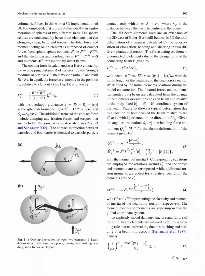
The contact force is calculated as a Hertz contact bythe overlapping distance ξ of spheres, by the Young’smodulus of particle E p, their Poisson ratio ν p and radiiRi , R j . In detail, the force on element j in the positionri j relative to element i (see Fig. 1a) is given by
�Fovj = 4
3
E p√
Reff
(1 − ν2)ξ
3/2ij r ′
ij, (1)
with the overlapping distance ξ = Ri + R j − |ri j |as the sphere deformation, 1/Ref f = 1/Ri + 1/R j andr ′
i j = ri j/|ri j |. The additional terms of the contact forceinclude damping and friction forces and torques thatare included the same way as described in (Pöscheland Schwager 2005). The contact interaction betweenparticles and boundaries is identical to particle-particle
Fig. 1 a Overlap interaction between two elements. b Beamdeformation in the beam x−y plane, showing the resulting ben-ding, shear forces and torques
contact, only with ξ = Ri − rip, where rip is thedistance between the particle centre and the plane.
The 3D beam elements used are an extension ofthe 2D case of Euler–Bernoulli beams. In 3D the totaldeformation of a beam is calculated by the superpo-sition of elongation, bending and shearing in two dif-ferent planes and torsion. The force acting on elementj connected to element i due to the elongation ε of theconnecting beam is given by
�Feloj = −Eb Abεr ′
i j , (2)
with beam stiffness Eb, ε = (|ri j | − l0)/ l0, with theinitial length of the beam l0 and the beam cross sectionAb defined by the initial elements positions during themodel construction. The flexural forces and momentstransmitted by a beam are calculated from the changein the elements orientations on each beam end relativeto the body-fixed èb
x − èby − èb
z coordinate system ofthe beam. Figure 1b shows a typical deformation dueto a rotation of both ends of the beam relative to theèb
z -axis, with èbx oriented in the direction of r ′
i j . Giventhe angular orientations θ z
i , θ zj , the bending force and
moment Qz,bj , Mz,b
j for the elastic deformation of thebeam is given by
�Qz,bj = 3Eb I
(θ z
i +θ zj
)
L2 èby,
�Mz,bj = Eb I
(θ zi −θ z
j )
L èby +
( �Qz,bj × ∣∣�ri j
∣∣ èbx
),
(3)
with the moment of inertia I . Corresponding equationsare employed for rotations around èb
y , and the forcesand moments are superimposed while additional tor-sion moments are added for a relative rotation of theelements around èb
x ,
�Mx .bj = −Gb I tor
(θ x
j − θ xi
)
Lèb
x , (4)
with Gb and I tor representing the elasticity and momentof inertia of the beams for torsion, respectively. Theelement forces and moments are superimposed in theglobal coordinate system.
To explicitly model damage, fracture and failure ofthe solid, beam elements are allowed to fail by a brea-king rule that takes breaking due to stretching and ben-ding of a beam into account (Herrmann et al. 1989),namely(
ε
εth
)2
+ max(|θi | ,
∣∣θ j∣∣)
θth≥ 1, (5)
123

108 F. K. Wittel et al.
with the longitudinal strain ε = �l/ l0 and the generalrotation angles θi and θ j of the beam ends and usingεth and θth as the respective threshold values. Note thatEq. 5 has the form of the von Mises plasticity criterion.The threshold values are taken randomly for each beam,according to the Weibull distributions
P(εth) = kε0
(εthε0
)k−1exp
(−
(εthε0
)k)
,
P(θth) = kθ0
(θthθ0
)k−1exp
(−
(θthθ0
)k)
.
(6)
Here k, εo and θo are model parameters, controlling thewidth of the distributions and the average values for εth
and θth respectively. Low disorder is obtained by usinglarge k values, large disorder by small k.
The time evolution of the system is followed solvingthe equations of motion for the translation and rotationof all elements using a 6th-order Gear predictor-corrector algorithm. The dynamics of the particle rota-tions is described using quaternions (Rapaport 2004).Thebreaking rulesareevaluated ineach time increment.Thebeambreaking is irreversible, andbrokenbeamsareexcluded from the model for consecutive time steps.
2.1 Model construction and calibration
In order to avoid artefacts arising from the system topo-logy, like anisotropy, leading to non uniform wave pro-pagation or preferred crack paths, special attention isgiven to the model construction. We first start using27000 spherical elements that are initially placed on alarge regular cubic lattice but with random velocities torandomize the system. The elements are bi-disperse insize with equal portions of Dmin = 0.95Dmax . Aftersome randomization time, a central potential, located inthe centre of the simulation box, is imposed to compactthe elements. The system is evolved until all particlevelocities are reduced to nearly zero due to small dissi-pative forces. We end up with a random, nearly spheri-cal agglomerate of particles that now get connected bybeam-truss elements through a Delaunay triangulation.Note that not only contacting particles are connected.We examined the topology by looking at the angularcorrelations with neighbors and found no proof withrespect to crystallization. After the elements are initia-ted, their Young’s modulus is slowly increased whilethe centripetal gravitational field is decreased, leadingto an expansion of the system. Finally the bond lengths
and orientations are reset so that no initial residualstresses are present in the system and the system is trim-med to the desired shape by element removal. The beamlattice is equivalent to a material discretisation using adual Voronoi tessellation of the domain (Bolander andSukumar 2005; Lilliu and Van Mier 2003; Yip et al.2006). The microscopic properties like the elastic andfailure properties of elements and bonds are calibratedto obtain the desired macroscopic Young’s modulus,Poisson’s ratio and strength (values see Table 1).
The trimmed spherical specimen is located closeto a plate and an impact velocity vi in the negativez-direction is assigned to the system. The computationcontinues until no breaking activity is registered for50 µs.
For comparative reasons we calculate the evolutionof the stress field by an explicit Finite Element (FE)analysis with ABAQUS. The FE model consists of axi-symmetric, linear 4-node elements, using the macro-scopic properties measured on the DEM sample before(see Table 1). Symmetry boundary conditions are defi-ned along the central axis of the particle and rigidground plate. Figure 2a compares the shock wave of theimpact using our DEM and the FEM simulation. Notethat the measured wave velocity of both simulations isconsistent with the analytical values (see Table 1). Thetime evolution of the elastic energy in the system wasfound to be in excellent agreement as well.
3 Mechanisms in impact fragmentation
An important step in manipulating fragmentationprocesses is identifying and understanding the differentfragmentation mechanisms in their order of occurrence(Fig. 3a–d) and with increasing impact energy(Fig. 6a–f). The first damage mechanism observed isdiffuse damage in a region approximately D/4 fromthe target plane (see Fig. 3a). The diffusive damageoccurs due to a bi-axial stress state in the x−y plane (seeFig. 2b), superimposed by compressive stress directedz-wards (Andrews and Kim 1998).
As time evolves, meridional cracks form. Their ori-gin is explored in Fig. 4a, where positions and temporalevolution of the broken bonds are plotted in side andtop view, showing well defined meridional crack planesthat grow from the inside towards the lateral and upperfree surfaces. To understand the angular separation ofthe crack planes, the angular distribution of the broken
123

Mechanisms in impact fragmentation 109
Table 1 Typical modelproperties of the DEMmodel e.g. calibrated on a(16 × 8 × 8) mm3 sizedsample in quasi-statictensile and compressivetests
ParticlesStiffness E p 3 GPaDiameter D1 0.5 mmDensity ρ 3 t/m3
BeamsStiffness Eb/Gb 6 GPaAverage length L 0.5 mmDiameter D 0.5 mmStrain threshold ε0 0.02 –Bending threshold θ0 3 ◦Shape parameter κ 0.3 –Hard plateStiffness Ew 70 GPaInteractionFriction coefficient µ 1 –Damping coefficient γn 0.25 s−1
Friction coefficient γt 0.05 s−1
SystemTime increment �t 1e–8 sNumber of particles N p 22013 –Number of beams N b 135948 –Solid fraction 0.65Sphere diameter D 16 mmMacroscopic properties DEMSystem stiffness E 7.4 ± 0.5 GPaPoisson’s ratio ν 0.2 –Density ρ 1920 kg/m3
System strength σc 110 MPaDEM FEM
Comparisonp-Wave speed 2210 ± 100 2270 ± 20 m/sContact time 31.4 31.4 µs
bonds for different times are plotted in Fig. 4b by usingg(θ ) as the probability of finding two broken bonds as afunction of the angular separation θ in the x−y plane.The peaks in g(θ ) clearly indicate meridional planes.For the velocity shown in Fig. 4, meridional cracks areseparated by an average angle of about 60◦, and theybecome evident approx. 14 µs after impact.
For various realizations and materials, the positionof the meridional cracks changed, but not their ave-rage angular separation, even though for strong disor-der (Eq. 6), a larger amount of uncorrelated damageoccurs. From the FE calculations and the damage orien-tation correlation plot (Fig. 4b) no crack orientationis preferred inside of the undamaged biaxial tensilezone. However, many micro cracks weaken this zone,decreasing its effective stiffness. Around the weake-ned core, the material is intact and under high circum-ferential tensile stress. Inside this ring shaped zone,we observe the onset of the meridional cracks whenwe back-trace them. With increasing impact velocity,
the angular separation of crack planes decreases andthus more wedge-shaped fragments form. Obviouslythis effect can not be explained by arguments basedon quasi-static stress analysis. However the observa-tion can be explained in the spirit of Mott’s fragmen-tation theory for expanding rings (Mott 1946). Once ameridional crack forms, stress is released in the neigh-bourhood and the stress release fronts spread with aconstant velocity leading to a decreasing probabilityfor fracture in neighbouring regions. However in thestressed regions, the strains still increase due to theexternal loading, and the fracture probability along withit. The average size of the wedge shaped fragmentstherefore is determined by the relationship betweenthe rate at which cracks nucleate and the velocity ofthe stress release wave. The higher the strain rate, thehigher the crack nucleation rate and the more meri-dional cracks are formed. Measurements of the strainrate at arbitrary positions inside the bi-axially loadedzone showed a clear correlation between impact
123

110 F. K. Wittel et al.
Fig. 2 Cross sections of thehalf sphere. a Shock-wavepropagation obtained fromDEM and FEM simulationsfor vi = 117 m/s. Elementsare coloured according totheir accelerationmagnitude. b Stress fieldsfrom the continuum model.The left side shows theshear stresses in globalcoordinates from 0 to400 MPa (black to white)while on the right side,circumferential stresses inspherical coordinates aregiven, ranging from 0 to130 MPa (black to white).Note the direction of impactcorresponds to themeridional direction
velocity and strain rate. Even though a compact sphereand not a ring is fragmented, meridional cracks ini-tiate in a highly stressed ring shaped region and Mott’stheory can qualitatively explain the decrease of angu-lar separation of wedge shaped fragments with increa-sing impact velocity. If enough energy is accessible,some of the meridional plane cracks propagate out- andupwards, fragmenting the sample into wedge shapedfragments like “orange slices”.
As the sphere moves further towards the plate, a ringof broken bonds forms by shear failure at the borderof the contact disc (see Figs. 2b, 3). When the samplebegins to detach from the plate, a cone has been formedby a ring crack that propagated from the surface to theinside of the material at approximately 45◦. The resul-ting cone shaped fragments have a smaller reboundvelocity than other fragments due to dissipated elasticenergy by fracture, as can be seen in (Fig. 3d).
If the imparted energy is high enough, oblique planecracks, also called secondary cracks may still fragmentthe large fragments further (see Fig. 5a). These secon-dary cracks are similar to oblique cracks observed in 2D
simulations (Behera et al. 2005; Potapov et al. 1995).Figure 5 compares the crack patterns obtained from a2D DEM simulation that uses polygonal particles. Notethat in 2D simulations, we observe an unnatural stron-gly fragmented cone of numerous single element frag-ments and meridional cracks can of course not form.
4 Scaling regimes in fragmentation
For practical applications of comminution processes,the amount of energy necessary to fragment a mate-rial is an important parameter. By varying the impactenergy, in fragmentation simulations and experimentstwo distinct regimes can be identified: below a criti-cal energy fracture and damage takes place (Andrewsand Kim 1998; Gilvarry and Bergstrom 1962; Thorntonet al. 1999), while above fragments form. Figure 6a–fshows examples of final crack patterns after impactwith increasing impact energy. For smaller impact ener-gies it is possible to observe meridional cracks thatreach the sample surface above the contact point, but a
123

Mechanisms in impact fragmentation 111
Fig. 3 Simulationsnapshots of verticalmeridional cuts, showingbroken bonds (dark colour).a Diffuse damage due tobi-axial stress state. bFormation of a ring ofbroken bonds by shearfailure. c Theses brokenbonds evolve into cracksthat propagate inside thesample. d Detachment ofthe lower fragments
large piece with cracks remains (Fig. 6a, b). As the ini-tial energy increases, some of the meridional cracks arethe first ones to reach the top free surface of the sphere,fragmenting the material into typically two to four frag-ments of wedge shape (Fig. 6c). Therefore meridionalcracks are called primary cracks. As described ear-lier, increasing energy leads to secondary oblique planecracks that further fragment the orange slice shapedfragments (Fig. 6d–f). The shape and number of largefragments simulated for smaller impact energies, aswell as the location and orientation of oblique secon-dary cracks for larger energies, are in good agreementwith experiments (Khanal et al. 2004; Schubert et al.2005; Wu et al. 2004).
For velocities smaller then the threshold velocityvth , the sample is damaged by the impact but not frag-mented. In particular, in 2D simulations a continuousphase transition from the damaged to the fragmentedstate was found (Behera et al. 2005; Kun and Herr-mann 1999). Analogous to their analysis, the final stateof the system is analyzed by measuring the mass ofthe two largest fragments, as well as the average frag-ment size. Note that the average mass M2/M1, withMk =
N fi Mk
i − Mkmax excludes the largest fragment.
We can see in Fig. 7a that below the threshold valuevth = 115 m/s the largest fragment in our system hasalmost the total mass of the system with the secondlargest one being consequently nearly zero. Hence, the
123

112 F. K. Wittel et al.
Fig. 4 a Broken bondscoloured according to thetime of failure. b Angulardistribution functions ofbroken bonds (x−yprojection) as a function ofthe angular separation(vi = 120 m/s)
Fig. 5 a 3D DEMsimulation at vi = 140 m/sexemplifying the secondarycracks compared to b 2Dsimulations using polygonsas elementary particles(Behera et al. 2005)
system was only damaged and not fragmented. For v >
vth the mass of the largest fragment rapidly decreasesand the second largest and average fragment massesincrease, showing a maximum at 117.5 m/s for our sys-tem. This is in very good qualitative agreement withfragmentation simulations on different geometries andloading situations (Behera et al. 2005; Kun and Herr-mann 1999; Wittel et al. 2005), indicating that 3D
fragmentation simulations also show this phase tran-sition from damage to fragmented state.
4.1 Fragment mass distributions
Technologically the fragment mass distributions are themost important outcome of fragmentation processes.Experimental and numerical fragmentation studies
123

Mechanisms in impact fragmentation 113
Fig. 6 Final crack patternsfor different initialvelocities. Elements areprojected to their initialpositions for clearer view ofthe crack patterns. Intactbonds are colouredaccording to the finalfragment they belong, whilegray dots are added at thepositions of broken beams
123

114 F. K. Wittel et al.
Fig. 7 a Scaling of masses.First, second largest andaverage fragment mass as afunction of the impactvelocity. b Fragment massdistribution for differentinitial velocities. Thestraight line corresponds toa power-law with exponentτ = −1.9
Fig. 8 a Fragment sizedistribution weighted bymass for initial velocities.b Fragment massdistribution forv = 122.5 m/s and differentdisorder in the bondbreaking thresholds. Thesolid lines correspond to apower law with anexponential cut-off forlower masses and theWeibull distribution forlarge masses (Eq. 8)
show that the mass distributions follow a power law inthe range of small fragments, with a universal exponentdepending on the fragmentation mechanisms. The massdistribution for large fragments can be represented byan exponential cut-off of the power law. The fragmentmass distribution is usually given in terms of F(m),that expresses the probability density of finding a frag-ment with mass m between m and m + �m, with mbeing the fragment mass normalized by the total sys-tem mass Mtot . The fragment mass distributions forour 3D simulations are shown in Fig. 7b for differentimpact velocities vi averaging over 36 realizations. Ifvi < vth , F(m) has a peak at low fragment masses cor-responding to very small fragments. However the pro-nounced isolated peaks near the total mass of the systemcorrespond to the large damaged, but still unfragmen-ted system (see also Fig. 6a, b). Note that fragments atintermediate mass range are not present in the damageregime. Around and above vth , F(m) exhibits a powerlaw dependence F(m) ∼ m−τ for intermediate masses,(dashed line in Fig. 7b) with τ = 1.9 ± 0.2 (Linna et al.
2005; Turcotte 1986). However a local maximum canbe observed for large fragments, indicating that they areformed by mechanisms that are distinct from the onesforming small fragments. The primary cracks show anangular distribution with an average separation bet-ween 45–60◦ resulting in fragment masses in the orderof 10% of Mtot . This corresponds to the range of massesthat present the broad peak in the fragment mass dis-tribution.
To give a better representation of the large frag-ments, the cumulative size distribution of the fragmentsweighted by mass, Q3 is studied in Fig. 8a. Q3 is cal-culated by summing the mass of all fragments smallerthan a given size s, which is estimated as the diame-ter of a sphere with identical mass. Note that the valuesare normalized by the sample diameter D. The shape ofthe size distribution for large fragments can be descri-bed by a two-parameter Weibull distribution, namelyQ3(s) = 1 − exp[−(s/sc)
ks] (dashed line in Fig. 8a,with sc = 0.75 and ks = 5.8). The Weibull distributionseems suitable, since it has been empirically found to
123

Mechanisms in impact fragmentation 115
describe many fracture experiments for brittle mate-rials (Lu et al. 2002). For increasing impact velocityvi , the average fragment size decreases, which is alsoin agreement with experimental findings by (Antonyuket al. 2006; Cheong et al. 2004).
No dependence of the fragment mass distributionwith respect to material disorder (k in Eq. 6) was obser-ved (see Fig. 8b). This is in agreement with observationson the universality of the fragment size distributionwith respect to the breaking probability distribution(Åström et al. 2000). For the fragment mass distributionof (v ∼ vth) two distinct regimes can be identified (seeFig. 8b). For m < 1/40 (approx. 550 elements), F(m)
can be well described by the form
F(m) ∼ (1 − β)m−τ exp
(−m
�m0
)+ β exp
(−m
�m1
),
(7)
recently proposed by (Åström et al. 2004/2006). Thefirst term is associated to branching-merging processesdue to crack tip instabilities, while the second one ori-ginates from the Poissonian nucleation processes of thefirst dominating cracks. The parameter β expresses therelative importance of the two processes.
Furthermore, the scaling exponent τ only dependson the dimensionality of the system. The local maxi-mum for the large m can again be described by a two-parameter Weibull distribution
F(m) ∼(
kl
�ml
) (m
�ml
)kl−1
· exp
(−
(m
�ml
)kl)
, (8)
as discussed above. In Fig. 8b, Eqs. (7), (8) are plottedseparately with a dashed line, corresponding to a fit withvalues of m0 = 0.001 ± 0.001, m1 = 0.004 ± 0.001,ml = 0.3 ± 0.02 and kl = 1.9 ± 0.1. The good qua-lity of the fit allows for an estimate of the exponentof the power-law distribution in the small fragmentmass range to be τ = 2.2 ± 0.2. This composed massdistribution function is not observed for 2D simula-tions (Behera et al. 2005; Kun and Herrmann 1999)or 3D simulations of shell fragmentation (Wittel et al.2004/2005), where obviously meridional cracks are notpresent.
5 Conclusions
We showed the importance of the use of 3D simu-lations for fragmentation processes by using a DEM
simulation with 3D beam-truss elements for the particlecohesion. Due to this computationally more laboriousapproach, one is able to obtain a more realistic pictureof the fragmentation processes, the evolution of frag-mentation mechanisms and their consequences for thefragment mass distribution. To rationalize argumentsfor the fracture initiation, continuum solutions for thestress field were utilized. It was shown that 2D repre-sentations for fragmenting systems are not capable ofcapturing fragmentation by meridional cracks, whichis the primary cracking mechanism. We showed thatmicro cracks form inside the sample in a region abovethe compressive cone long time before they are experi-mentally observed from the outside, if at all. They coa-lesce to initiate fracture in meridional fracture planes,resulting in a small number of large wedge shapedfragments. An explanation for the decrease in theirangular separation could be found in the Mott frag-mentation model. The resulting fragment mass distri-bution is described by a power law regime for smallfragments and a broad peak for large fragments thatcan be fitted by a two-parameter Weibull distribution,in agreement with experimental results (Antonyuk et al.2006; Cheong et al. 2004; Lu et al. 2002; Salman et al.2002). Even though the results are valid for materialswith various disorders, they are limited to the class ofbrittle, disordered media; however extensions to frag-mentation with ductile materials are in progress. Ano-ther class of interesting questions deal with the problemof size effects, the influence of multi-disperse particlesor the stiffness contrast of particles and beam-elements.For technological applications studies on the influenceof target geometries and the optimization potential toobtain desired fragment size distributions or to reduceimpact energies are of broad interest.
References
Andrews EW, Kim KS (1998) Threshold conditions for dynamicfragmentation of ceramic particles. Mech Mater 29:161–180. doi:10.1016/S0167-6636(98)00014-3
Andrews EW, Kim KS (1999) Threshold conditions for dynamicfragmentation of glass particles. Mech Mater 31:689–703.doi:10.1016/S0167-6636(99)00024-1
Antonyuk S, Khanal M, Tomas J, Heinrich S, Morl L (2006)Impact breakage of spherical granules: experimental studyand DEM simulation. Chem Eng Process 45:838–856.doi:10.1016/j.cep.2005.12.005
Arbiter N, Harris CC, Stamboltzis GA (1969) Single fracture ofbrittle spheres. T Soc Min Eng 244:118–133
123

116 F. K. Wittel et al.
Åström JA (2006) Statistical models of brittle fragmentation.Adv Phys 55:247–278. doi:10.1080/00018730600731907
Åström JA, Holian BL, Timonen J (2000) Universality infragmentation. Phys Rev Lett 84:3061–3064. doi:10.1103/PhysRevLett.84.3061
Åström JA, Linna RP, Timonen J, Moller PF, Oddershede L(2004) Exponential and power-law mass distributions inbrittle fragmentation. Phys Rev E Stat Nonlin Soft MatterPhys 70:026104. doi:10.1103/PhysRevE.70.026104
Behera B, Kun F, McNamara S, Herrmann HJ (2005) Fragmen-tation of a circular disc by impact on a frictionless plate.J Phys-Condens Mater 17:S2439–S2456
Bicanic N (2004) Discrete element methods. In: Stein E, de BorstR Hughes T (eds) Encyclopedia of computational mecha-nics: fundamentals. Wiley pp 311–337
Bolander JE, Sukumar N (2005) Irregular lattice model for qua-sistatic crack propagation. Phys Rev B 71:094106. doi:10.1103/PhysRevB.71.094106
Chau KT, Wei XX, Wong RHC, Yu TX (2000) Fragmentationof brittle spheres under static and dynamic compressions:experiments and analyses. Mech Mater 32:543–554. doi:10.1016/S0167-6636(00)00026-0
Cheong YS, Reynolds GK, Salman AD, Hounslow MJ (2004)Modelling fragment size distribution using two-parameterWeibull equation. Int J Miner Process 74:S227–S237.doi:10.1016/j.minpro.2004.07.012
Cundall PA, Strack ODL (1979) Discrete numerical-model forgranular assemblies. Geotechnique 29:47–65
Diehl A, Carmona HA, Araripe HA, Andrade JS, Farias GA(2000) Scaling behavior in explosive fragmentation. PhysRev E Stat Phys Plasmas Fluids Relat Interdiscip Topics62:4742–4746. doi:10.1103/PhysRevE.62.4742
Gilvarry JJ, Bergstrom BH (1961) Fracture of brittle solids:1. Distribution function for fragment size in single fracture.J Appl Phys 32:400–410
Gilvarry JJ, Bergstrom BH (1962) Fracture of brittle solids.III. Expermental results on the distribution of fragment sizein single fracture. J Appl Phys 33:3211–3213
Herrmann HJ, Roux S (eds) (1990) Statistical models for thefracture of disordered media. North-Holland, Amsterdam
Herrmann HJ, Hansen A, Roux S (1989) Fracture of Disordered,elastic Lattices in 2 dimensions. Phys Rev B 39:637–648.doi:10.1103/PhysRevB.39.637
Khanal M, Schubert W, Tomas J (2004) Ball impactand crack propagation—simulations of particle com-pound material. Granul Matter 5:177–184. doi:10.1007/s10035-003-0149-3
Kun F, Herrmann HJ (1996a) Fragmentation of collidingdiscs. Int J Mod Phys C 7:837–855. doi:10.1142/S0129183196000697
Kun F, Herrmann HJ (1996b) A study of fragmentation processesusing a discrete element method. Comput Methods Appl M138:3–18. doi:10.1016/S0045-7825(96)01012-2
Kun F, Herrmann HJ (1999) Transition from damage to fragmen-tation in collision of solids. Phys Rev E Stat Phys PlasmasFluids Relat Interdiscip Topics 59:2623–2632. doi:10.1103/PhysRevE.59.2623
Lilliu G, Van Mier JGM (2003) 3D lattice type fracture modelfor concrete. Eng Fract Mech 71:927–941. doi:10.1016/S0013-7944(02)00158-3
Linna RP, Åström JA, Timonen J (2005) Dimensional effectsin dynamic fragmentation of brittle materials. Phys RevE Stat Nonlin Soft Matter Phys 72:015601. doi:10.1103/PhysRevE.72.015601
Lu CS, Danzer R, Fischer FD (2002) Fracture statistics of brit-tle materials: weibull or normal distribution. Phys RevE Stat Nonlin Soft Matter Phys 65:067102. doi:10.1103/PhysRevE.65.067102
Majzoub R, Chaudhri MM (2000) High-speed photography oflow-velocity impact cracking of solid spheres. Philos MagLett 80:387–393. doi:10.1080/095008300403521
Meibom A, Balslev I (1996) Composite power laws in shockfragmentation. Phys Rev Lett 76:2492–2494. doi:10.1103/PhysRevLett.76.2492
Mott NF (1946) Fragmentation of spherical cases. Proc R SocLond A Math Phys Sci 189:300–308. doi:10.1098/rspa.1947.0042
Oddershede L, Dimon P, Bohr J (1993) Self-organized criticalityin fragmenting. Phys Rev Lett 71:3107–3110. doi:10.1103/PhysRevLett.71.3107
Potapov AV, Campbell CS (1996) A three-dimensional simula-tion of brittle solid fracture. Int J Mod Phys C 7:717–729.doi:10.1142/S0129183196000594
Potapov AV, Campbell CS (1997) The two mechanisms of par-ticle impact breakage and the velocity effect. Powder Tech-nol 93:13–21. doi:10.1016/S0032-5910(97)03242-7
Potapov AV, Hopkins MA, Campbell CS (1995) A 2-dimensionaldynamic simulation of solid fracture. I. Description ofthe model. Int J Mod Phys C 6:371–398. doi:10.1142/S0129183195000277
Pöschel T, Schwager T (2005) Computational granular dyna-mics: models and algorithms. Springer-Verlag, Berlin
Rapaport DC (2004) The art of molecular dynamics simulation.Cambridge University Press, Cambridge
Salman AD, Biggs CA, Fu J, Angyal I, Szabo M, Hounslow MJ(2002) An experimental investigation of particle fragmen-tation using single particle impact studies. Powder Technol128:36–46. doi:10.1016/S0032-5910(02)00151-1
Schönert K (2004) Breakage of spheres and circular discs.Powder Technol 143–144:2–18
Schubert W, Khanal M, Tomas J (2005) Impact crushing ofparticle-particle compounds—experiment and simulation.Int J Miner Process 75:41–52. doi:10.1016/j.minpro.2004.01.006
Thornton C, Yin KK, Adams MJ (1996) Numerical simulationof the impact fracture and fragmentation of agglomerates.J Phys D Appl Phys 29:424–435. doi:10.1088/0022-3727/29/2/021
Thornton C, Ciomocos MT, Adams MJ (1999) Numerical simu-lations of agglomerate impact breakage. Powder Technol105:74–82. doi:10.1016/S0032-5910(99)00120-5
Tomas J, Schreier M, Groger T, Ehlers S (1999) Impact crushingof concrete for liberation and recycling. Powder Technol105:39–51. doi:10.1016/S0032-5910(99)00116-3
Turcotte DL (1986) Fractals and fragmentation. J Geophys Res-solid 91:1921
Wittel FW, Kun F, Herrmann HJ, Kröplin BH (2004) Fragmen-tation shells. Phys Rev Lett 93:035504
Wittel FW, Kun F, Herrmann HJ, Kröplin BH (2005) Breakup ofshells under explosion and impact. Phys Rev E Stat
123

Mechanisms in impact fragmentation 117
Nonlin Soft Matter Phys 71:016108. doi:10.1103/PhysRevE.71.016108
Wu SZ, Chau KT, Yu TX (2004) Crushing and fragmentation ofbrittle spheres under double impact test. Powder Technol14–34:41–55
Yip M, Li Z, Liao BS, Bolander JE (2006) Irregular lattice modelsof fracture of multiphase particulate materials. Int J Fract140:113–124. doi:10.1007/s10704-006-7636-6
123