the impact on catalyst performance due to poisoning & fouling mechanisms
TRANSCRIPT
Refinery Process Stream Purification Refinery Process Catalysts Troubleshooting Refinery Process Catalyst Start-Up / Shutdown Activation Reduction In-situ Ex-situ Sulfiding Specializing in Refinery Process Catalyst Performance Evaluation Heat & Mass Balance Analysis Catalyst Remaining Life Determination Catalyst Deactivation Assessment Catalyst Performance Characterization Refining & Gas Processing & Petrochemical Industries Catalysts / Process Technology - Hydrogen Catalysts / Process Technology – Ammonia Catalyst Process Technology - Methanol Catalysts / process Technology – Petrochemicals Specializing in the Development & Commercialization of New Technology in the Refining & Petrochemical Industries
Web Site: www.GBHEnterprises.com
GBHE Technical Bulletin CTB #23
The Impact on Catalyst Performance due to poisoning & fouling mechanisms
Gerard B. Hawkins
Catalysts promote chemical reactions or accelerate the rate at which a chemical reaction approaches equilibrium. The catalyst provides a suitable surface for reactants to adsorb onto and for products to desorb from. The role of the catalyst is to lower the activation energy of a reaction by providing a suitable reaction pathway and is applicable to all types of catalysis, i.e., homogeneous, heterogeneous and enzymatic catalysis Heterogeneous catalysis is a surface phenomenon. An essential precursor to any reaction is the adsorption of reactants onto the catalyst surface followed by the desorption of the products from the catalyst surface. It is not therefore surprising that catalysts are very sensitive to any impurities (or poisons) that can impact upon and affect that active surface. Poisons, as the name implies, have a deleterious effect upon the catalyst surface, in contrast to promoters that can enhance both catalyst activity and selectivity. A poison can be simply defined as any substance that changes the chemical or physical properties of the surface, leading to an adverse effect in terms of activity or life. Poisons impair the catalyst performance by reducing catalyst activity via competitive adsorption onto the active sites or by alloy formation with the active sites and the result is to effectively remove these active centres from the desired reaction scheme. Poisoning by a chemisorptions mechanism is directly due to the fact that the poison is more strongly absorbed than a reactant. Poisons can sometimes be beneficially introduced into a process stream to modify activity or surface acidity; selective inhibition of some active sites by partial poisoning to improve catalyst selectivity is employed in some hydrogenation / dehydrogenation reactions. Most of the catalytic reaction encountered in hydrocarbon processing are performed with porous catalysts to provide an adequate surface area for metals dispersion and subsequent reaction, and are classified as diffusion limited to some degree. As a consequence of this, only a small amount of a particular contaminant, even present in trace concentrations, is actually necessary to block off access to the huge inner pore structure and thus significantly reduce activity.
Refinery Process Stream Purification Refinery Process Catalysts Troubleshooting Refinery Process Catalyst Start-Up / Shutdown Activation Reduction In-situ Ex-situ Sulfiding Specializing in Refinery Process Catalyst Performance Evaluation Heat & Mass Balance Analysis Catalyst Remaining Life Determination Catalyst Deactivation Assessment Catalyst Performance Characterization Refining & Gas Processing & Petrochemical Industries Catalysts / Process Technology - Hydrogen Catalysts / Process Technology – Ammonia Catalyst Process Technology - Methanol Catalysts / process Technology – Petrochemicals Specializing in the Development & Commercialization of New Technology in the Refining & Petrochemical Industries
Web Site: www.GBHEnterprises.com
Sometimes catalyst activity is decreased without affecting the selectivity when some of the sites are totally deactivated while others are unaffected. If, however, some active sites are modified without losing all activity, then the relative rates of different reactions may change to give different catalyst selectivity. We generally distinguish between plant mal-operation, which can cause catalyst fouling, and thus catalyst deactivation, and true poisoning. In plant mal-operation the impurity levels are higher and transient in nature. Typically poisons and foulants are thought of as separate entities, although both cause catalysts to deactivate. Typical foulants are dust or catalyst particulates, tramp iron contamination or even coke formation. The first two enter the catalyst bed with the feedstock whilst coking is often due to unselective reactions within the catalyst bed causing a dramatic increase in pressure drop. Poisons deactivate catalysts with lower surface areas more easily than those manufactured with high surface areas. This is illustrated in the table below for an effective contamination of 500 ppmw. The steam reforming catalyst has the lowest surface area due to the stringent requirements for high stability and robustness because of the high temperature of operation compared to the other refinery duties. The active metal is not so well dispersed due to the low surface area carrier and the effect of 500 ppmw impurity is an order of magnitude higher per unit surface area and therefore more active metal per unit surface area is affected. This is a rather simplistic way of looking at a complex poisoning problem but does highlight the severe effect of even low levels of contaminants on a catalyst and consequently, the performance in service. Catalyst Type %metal
oxide Surface area (m2/g)
Wt. Metal oxide per unit surface area
ppm impurities per unit surface area
Cat. Reforming 1.0 200 0.00005 2.5 Hydrodesulphurization 16 300 0.0005 1.7 Catalytic Rich Gas 60 150 0.004 3.3 Steam Reforming 15 10 0.015 50
Effective contamination of 500 ppmw
Refinery Process Stream Purification Refinery Process Catalysts Troubleshooting Refinery Process Catalyst Start-Up / Shutdown Activation Reduction In-situ Ex-situ Sulfiding Specializing in Refinery Process Catalyst Performance Evaluation Heat & Mass Balance Analysis Catalyst Remaining Life Determination Catalyst Deactivation Assessment Catalyst Performance Characterization Refining & Gas Processing & Petrochemical Industries Catalysts / Process Technology - Hydrogen Catalysts / Process Technology – Ammonia Catalyst Process Technology - Methanol Catalysts / process Technology – Petrochemicals Specializing in the Development & Commercialization of New Technology in the Refining & Petrochemical Industries
Web Site: www.GBHEnterprises.com
Poisons may be deposited on and remain fixed to the catalyst surface – permanent poisons- or are deposited on the surface and may be removed during the course of the reaction or by some remedial post reaction treatment – temporary poisons. This implies that the loss of activity – selectivity may be substantially recovered if the source of poisoning is removed and remedial action taken to adequately clean the catalyst surface In all cases, as the name implies, there is a significant effect on the catalysts performance both from direct and indirect effects. The extent of any poisoning effects depends upon the level of poison deposited on the catalyst and the secondary effects which result from induced changes to the catalyst surface by process conditions. The primary effects of low levels of poisons are often the precursor to significant changes in catalyst structure and activity. Poisons may simply lie on the catalyst surface and physically block access to the large inner pore structure or be strongly adsorbed onto and react with catalytic sites changing the structure of the catalyst surface. Changes in catalyst surface chemistry are often reflected in changes to the activity – selectivity of the process. In severe cases of poisoning the reaction mechanisms are substantially modified, allowing non-selective secondary reactions to predominate with a loss of process economics. To maintain the activity-selectivity and cycle life of the catalytic process, and to retard unselective side reactions, it is imperative that the catalyst surface is maintained in a poison free ‘clean’ state. Unfortunately, it is impossible to completely remove all the potential contaminants and therefore prevent some degree of poisoning from occurring during normal process operations. Often, the usual effect of trace contamination is to slowly deactivate a catalyst and permit an acceptable service life to be achieved but catastrophic failure can occur depending upon the particular poison and the concentration level. The main sources of poisons are the feedstock to be processed but additional sources include steam-raising systems and occasionally the catalyst itself can be the source. Sulfur from non-optimum desulfurization and inorganic contaminants (carried over silica sodium, calcium ions.) from a steam drum are fairly common. Catalyst suppliers also need to ensure that residual sulfate and chloride levels are kept low during the manufacturing process.
Refinery Process Stream Purification Refinery Process Catalysts Troubleshooting Refinery Process Catalyst Start-Up / Shutdown Activation Reduction In-situ Ex-situ Sulfiding Specializing in Refinery Process Catalyst Performance Evaluation Heat & Mass Balance Analysis Catalyst Remaining Life Determination Catalyst Deactivation Assessment Catalyst Performance Characterization Refining & Gas Processing & Petrochemical Industries Catalysts / Process Technology - Hydrogen Catalysts / Process Technology – Ammonia Catalyst Process Technology - Methanol Catalysts / process Technology – Petrochemicals Specializing in the Development & Commercialization of New Technology in the Refining & Petrochemical Industries
Web Site: www.GBHEnterprises.com
The feed flow to a reactor generally ensures that poisons are deposited on the inlet catalyst and will be retained at the inlet (e.g., silica) or migrate further down through the bed (e.g. chloride, sulfurs.) Those poisons that are volatile will be easily removed as the temperature increases and hence we do not see significant contamination levels on the catalyst surface near the outlet of the bed where a reasonable temperature gradient exists from inlet to outlet. An example of this would be in a steam reformer duty. The distribution of the poison within the reactor and across the catalyst particles is determined by the kinetics of the poisoning reaction and the mobility of the poison. As poison concentrations are usually low and poisoning reactions fast, most poisoning reactions are strongly diffusion limited with consequent poison deposition near the outside of the catalyst pellet. Methanol synthesis catalysts employ copper as an active component. Copper catalysts are very susceptible to chloride attack and readily form copper chlorides, which because of their low melting points are sufficiently mobile to migrate from the exterior to the interior of the pellet. Chlorides can also react with some metals form volatile metal chloride species and increase the rate of sintering of the catalyst. The inlet section of the catalyst bed may have the highest reaction duty. Small changes to the activity of the inlet catalyst are therefore more important than are changes in activity to catalyst at higher temperatures and will have a major effect on the overall process. Poisoning, and the effects of poisoning, can be a complicated process to understand or model due to the various reaction pathways and mechanisms involved. The actual severity of a poisoning episode in commercial plants is dependent upon several inter-related factors. For example, feedstock composition, plant throughput, contaminant concentrations, duration of episode etc.. The effects of permanent poisons cannot be mitigated against, as the poisons cannot be adequately removed. Loss of activity may be reflected in a number of different ways but often is indicated by increased hydrocarbon slippage, reduction in cycle length, increased pressure drop across the catalyst, Blockages of the porosity, removal of active metal sites and agglomeration of the active metal by poisons often lead to an increase in the relative rate of carbon deposition. This can lead to severe process problems and the need for premature catalyst change-out.
Refinery Process Stream Purification Refinery Process Catalysts Troubleshooting Refinery Process Catalyst Start-Up / Shutdown Activation Reduction In-situ Ex-situ Sulfiding Specializing in Refinery Process Catalyst Performance Evaluation Heat & Mass Balance Analysis Catalyst Remaining Life Determination Catalyst Deactivation Assessment Catalyst Performance Characterization Refining & Gas Processing & Petrochemical Industries Catalysts / Process Technology - Hydrogen Catalysts / Process Technology – Ammonia Catalyst Process Technology - Methanol Catalysts / process Technology – Petrochemicals Specializing in the Development & Commercialization of New Technology in the Refining & Petrochemical Industries
Web Site: www.GBHEnterprises.com
A primary contaminant found in all virgin feedstocks is sulfur species. These compounds are poisons for the majority of catalytic processes, even at low ppb concentrations. The primary effects of sulfur poisoning are a significant loss in activity of the catalyst as the metal is effectively removed as a less active metal sulfide. Removal of the poisoning source of sulfur contamination may permit the loss in activity- selectivity to be recovered, as sulfur is a temporary poison, if the catalyst remained unchanged during the poisoning episode. This is only correct when the secondary effects of sulfur poisoning do not result in a change of catalyst structure and the original bulk catalyst state is retained. Secondary Effects. Sulfur poisoning of catalysts can have catastrophic consequences. Sulfur is readily absorbed on to active metal sites resulting in catalyst deactivation and changes in reaction selectivity. Catalytic processing of ‘heavy are very susceptible to carbon formation due to an increase in thermally induced dehydrogenation reactions in the sulfur poisoned catalyst areas. Carbon deposits once formed may be autocatalytic in further promoting dehydrogenation and thermal cracking of the hydrocarbon feedstock. The initially active catalyst is rapidly changed to a carbon encapsulated, heat absorbing, inert black body. Post treatment action to effectively remove the carbon deposition from a catalyst normally involves some form of oxidation to remove the carbon as carbon dioxide. C + O2 - CO2 Steaming at an elevated temperature is generally the method of choice but the elevated temperature and the steam atmosphere can induce sintering of the active metal sites. Also, if the coking has occurred within the pore structure then an aggressive oxidation may damage the catalyst due to the large evolution of gas as carbon dioxide causing internal stresses within the catalyst pellet. The build up of pressure can be sufficient to disintegrate the catalyst pellet. The loss of active surface area through temperature or hydrothermal ageing has the knock-on effect of reducing catalyst activity. High temperature stable metal oxide sites may also be formed in some processes in areas of deactivated catalyst that are subject to localized overheating due to carbon deposition. Under normal operating conditions it may not be possible to re-reduce the catalyst to the active metal sites and therefore the catalyst suffers an irreversible change.

Refinery Process Stream Purification Refinery Process Catalysts Troubleshooting Refinery Process Catalyst Start-Up / Shutdown Activation Reduction In-situ Ex-situ Sulfiding Specializing in Refinery Process Catalyst Performance Evaluation Heat & Mass Balance Analysis Catalyst Remaining Life Determination Catalyst Deactivation Assessment Catalyst Performance Characterization Refining & Gas Processing & Petrochemical Industries Catalysts / Process Technology - Hydrogen Catalysts / Process Technology – Ammonia Catalyst Process Technology - Methanol Catalysts / process Technology – Petrochemicals Specializing in the Development & Commercialization of New Technology in the Refining & Petrochemical Industries
Web Site: www.GBHEnterprises.com
Sulfur may be the primary initiating poison; carbon and steam the secondary major poisons. The effects of poisons are therefore a complex interplay of many factors involving both physical and chemical changes to a catalyst surface. The secondary effects of poisoning often have as significant effect as the primary causes. Removal of catalyst poisons from the feedstock to be utilized is essential and can only be achieved by close attention to desulfurization or other processes from which poisons emanate. In addition to increased control of the source of poisons the adoption of high performance ‘poison traps’ is an alternative avenue to explore. The extent of poisoning, as determined by most analytical techniques, is reported as a ‘bulk’ value. The true level of poisoning, as seen by the catalyst phase is probably several orders of magnitude higher as the poison is deposited on the surface where the active metal concentration is lower. Analysis of a deactivated catalyst needs to be supplemented by additional information, such as surface analysis and element distribution across the pellet.
Permanent Poisons
- Arsenic, lead, mercury, cadmium… - Silica, Iron Oxide…. Temporary Poisons - Sulfur, carbon
Typical Poisons in hydrocarbon processing
Sulfur Sulfur species are poisons for all catalytic processes employing reduced metals or metal oxides as the primary active phase. A sulfur compound strongly chemisorbs onto and reacts with the active catalytic sites altering the surface structure.
Refinery Process Stream Purification Refinery Process Catalysts Troubleshooting Refinery Process Catalyst Start-Up / Shutdown Activation Reduction In-situ Ex-situ Sulfiding Specializing in Refinery Process Catalyst Performance Evaluation Heat & Mass Balance Analysis Catalyst Remaining Life Determination Catalyst Deactivation Assessment Catalyst Performance Characterization Refining & Gas Processing & Petrochemical Industries Catalysts / Process Technology - Hydrogen Catalysts / Process Technology – Ammonia Catalyst Process Technology - Methanol Catalysts / process Technology – Petrochemicals Specializing in the Development & Commercialization of New Technology in the Refining & Petrochemical Industries
Web Site: www.GBHEnterprises.com
The actual chemistry involved can be complex as the metal sulfides are not always stoichiometric and can be polymorphic in nature. It has been reported that that the specific interaction depends upon the oxidation state of the sulfur impurity, i.e., how many electron pairs are available for bonding of s & p- valence electrons with d-orbitals of the metals and whether they are shielded by other ligands. The reported order of decreasing toxicity for sulfur poisons is: H2S< SO2 < S03 Changes in catalyst surface chemistry are reflected in changes to the activity-selectivity of the process. Sulfur is considered a temporary poison for many catalysts, such as nickel based steam reforming catalysts. This implies that the loss in activity-selectivity of the catalyst may be substantially recovered by removal of the source of contamination and the adsorbed sulfur poisoning the catalyst surface. The specific surface area and the porosity of the catalyst are important in determining how long the catalyst will continue to perform in the presence of sulfur. It is possible to recover most, if not all the activity-selectivity following a minor (or short duration) sulfur-poisoning excursion. In severe cases of sulfur poisoning the reaction mechanisms are substantially modified permitting non-selective secondary reactions to predominate. Severe sulfur poisoning invariably leads to carbon laydown on the catalyst surface. To maintain the activity-selectivity balance and cycle length of the catalytic process, and to retard unselective side reactions, it is essential that the catalyst surface is maintained in a ‘sulfur free clean’ state. The temporary effect of sulfur poisoning is used to advantage in the start up of high activity precious metal catalysts in Catalytic Reformers. The fresh catalyst has a very high initial activity and start-up conditions at feed-in may lead to thermal runaways, excessive hydrocracking and dehydrogenation reactions resulting in carbon deposition and loss of cycle life. Low levels of sulfur may be introduced to the catalyst during start-up to moderate the initial high activity by adsorbing on ‘super active’ sites that promote hydrogenolysis and coking. This pre-treatment with a poison then allows the feed-in to be controlled without excessive carbon laydown. Under normal run conditions, with sulfur free feedstock, sulfur adsorbed on the catalyst surface bleeds off and a stable activity is obtained.
Refinery Process Stream Purification Refinery Process Catalysts Troubleshooting Refinery Process Catalyst Start-Up / Shutdown Activation Reduction In-situ Ex-situ Sulfiding Specializing in Refinery Process Catalyst Performance Evaluation Heat & Mass Balance Analysis Catalyst Remaining Life Determination Catalyst Deactivation Assessment Catalyst Performance Characterization Refining & Gas Processing & Petrochemical Industries Catalysts / Process Technology - Hydrogen Catalysts / Process Technology – Ammonia Catalyst Process Technology - Methanol Catalysts / process Technology – Petrochemicals Specializing in the Development & Commercialization of New Technology in the Refining & Petrochemical Industries
Web Site: www.GBHEnterprises.com
Chlorides The effect of chloride poisoning is very similar to, but more rapid in action, than the thermal ageing of the catalysts. The chloride ion is very mobile and can migrate through the whole process gas system. It can then react with active metal sites (such as Ni or Cu) to prevent free access to these sites and so alter the structure of the reduced metal crystallites and so enhance the thermal sintering process. This type of ‘ageing’ is very destructive and because the structure has been destroyed, the catalyst cannot be properly regenerated even if the poison source is removed. The chloride ion is extremely reactive and so the symptoms of poisoning appear very quickly. Also, chlorides attack many metal alloy surfaces and induce stress corrosion cracking even at concentrations in the low ppm chloride range. The initial chloride contaminant can be present as organic or inorganic forms in the process feedstock or by inefficient removal in the boiler feed water system supplied from the demineralization units. It should also be stressed that many chlorides, particularly organic chlorides, have relatively high vapor pressures and so organic chlorides, such as solvents for maintenance work cleaning turbines etc, must also be banned from the sites to avoid possibilities of chloride ion ingress.
Boiler Feed water impurities The main impurities associated with a boiler feed water system are silica, sodium, calcium and other metal ions. Correct control of the demineralization plant and the steam system is crucial to minimize solids carryover into the process stream. The primary cause of industrial catalyst deactivation is due to a physical pore blocking or pore narrowing effect. The deposited contaminants hinder the transport of reactants into the active interior pore structure of the catalyst. Transport of the reactants becomes more difficult through increased diffusion resistance caused by the plugging in the mouth of the pores. Silica is often transported in the steam in the form of microencapsulated hydrated silica droplets, rather than actually dissolved in the steam, and a properly designed impingement plate or demister pad should reduce any solids carryover to acceptable limits.
Refinery Process Stream Purification Refinery Process Catalysts Troubleshooting Refinery Process Catalyst Start-Up / Shutdown Activation Reduction In-situ Ex-situ Sulfiding Specializing in Refinery Process Catalyst Performance Evaluation Heat & Mass Balance Analysis Catalyst Remaining Life Determination Catalyst Deactivation Assessment Catalyst Performance Characterization Refining & Gas Processing & Petrochemical Industries Catalysts / Process Technology - Hydrogen Catalysts / Process Technology – Ammonia Catalyst Process Technology - Methanol Catalysts / process Technology – Petrochemicals Specializing in the Development & Commercialization of New Technology in the Refining & Petrochemical Industries
Web Site: www.GBHEnterprises.com
Sodium can also be carried over and is destructive for catalyst surfaces, as it will react with deposited silica and other catalytically active components. Deactivation by silica is therefore a purely physical (and not a chemical) effect of particulates on the surface blocking access to the active sites. Deactivation in this manner, accompanied by subsequent carbon deposition, is a consequence of pore blocking mechanisms.
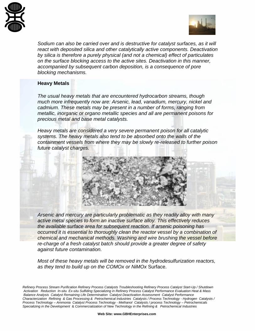
Heavy Metals The usual heavy metals that are encountered hydrocarbon streams, though much more infrequently now are: Arsenic, lead, vanadium, mercury, nickel and cadmium. These metals may be present in a number of forms, ranging from metallic, inorganic or organo metallic species and all are permanent poisons for precious metal and base metal catalysts. Heavy metals are considered a very severe permanent poison for all catalytic systems. The heavy metals also tend to be absorbed onto the walls of the containment vessels from where they may be slowly re-released to further poison future catalyst charges.
Arsenic and mercury are particularly problematic as they readily alloy with many active metal species to form an inactive surface alloy. This effectively reduces the available surface area for subsequent reaction. If arsenic poisoning has occurred it is essential to thoroughly clean the reactor vessel by a combination of chemical and mechanical methods. Washing and wire brushing the vessel before re-charge of a fresh catalyst batch should provide a greater degree of safety against future contamination. Most of these heavy metals will be removed in the hydrodesulfurization reactors, as they tend to build up on the COMOx or NiMOx Surface.
Refinery Process Stream Purification Refinery Process Catalysts Troubleshooting Refinery Process Catalyst Start-Up / Shutdown Activation Reduction In-situ Ex-situ Sulfiding Specializing in Refinery Process Catalyst Performance Evaluation Heat & Mass Balance Analysis Catalyst Remaining Life Determination Catalyst Deactivation Assessment Catalyst Performance Characterization Refining & Gas Processing & Petrochemical Industries Catalysts / Process Technology - Hydrogen Catalysts / Process Technology – Ammonia Catalyst Process Technology - Methanol Catalysts / process Technology – Petrochemicals Specializing in the Development & Commercialization of New Technology in the Refining & Petrochemical Industries
Web Site: www.GBHEnterprises.com
Industrial experience has shown that specially tailored pore size distributions within the HDS catalysts lead to increased metals removal and longer HDS cycle life before the need for a catalyst change-out. As concentrations should be limited to < 5ppb to protect catalysts. Vanadium and nickel are known poisons encountered in FCC units. Vanadium is initially present as organometallic species in the feedstock but this converts to a vanadium oxide species in the regenerator. The vanadium is then able to migrate to zeolite crystals and form a low melting eutectic with the silica alumina of the zeolite. This leads to a permanent destruction of the zeolite crystal structure and a significant loss in activity. Nickel is a poison when deposited on a catalyst surface as it can act as a strong dehydrogenation catalyst, which contributes, to carbon deposition. The effect of nickel is well documented in FCC units where nickel also increases the unwanted ‘light ends’ gas production. Nickel does not appear to affect the intrinsic activity but does adversely affect the selectivity of the reaction. Water can act as a poison for some catalysts, particularly those operating under reducing conditions. A number of mechanisms are possible for catalyst deactivation. Hydrothermal ageing is much more rapid than thermal sintering alone and leads to a permanent loss of activity through crystallite growth and agglomeration. Water may dissolve some soluble components within the catalyst system. For example, excess water has a negative impact upon catalytic reformer catalysts by dissolving chlorides from the catalyst and reducing the acid site density on the catalyst surface. This affects the ability of the catalyst to perform skeletal isomerization reactions. Organo nitrogen components can also be poisons for a variety of catalysts: such as hydrocracking and catalytic reforming catalysts. These compounds react to form ammonia which then neutralizes acid functions on the catalyst surface. Generally, this effect is reversible if the source of organo nitrogen is removed and the acidity restored. In catalytic reforming, the basic nitrogen compounds adsorb on the acid sites and reduce isomerization and cracking activity but do not appear to have little effect on dehydrogenation activity. Iron oxide is a known poison for many hydrocarbon processing catalysts. Unfortunately, iron is a known catalyst for many reactions itself and therefore can promote dehydrogenation reaction pathways, leading to carbon deposition on the catalyst surface.
Refinery Process Stream Purification Refinery Process Catalysts Troubleshooting Refinery Process Catalyst Start-Up / Shutdown Activation Reduction In-situ Ex-situ Sulfiding Specializing in Refinery Process Catalyst Performance Evaluation Heat & Mass Balance Analysis Catalyst Remaining Life Determination Catalyst Deactivation Assessment Catalyst Performance Characterization Refining & Gas Processing & Petrochemical Industries Catalysts / Process Technology - Hydrogen Catalysts / Process Technology – Ammonia Catalyst Process Technology - Methanol Catalysts / process Technology – Petrochemicals Specializing in the Development & Commercialization of New Technology in the Refining & Petrochemical Industries
Web Site: www.GBHEnterprises.com
Also, finely divided iron oxide is quite reactive with other contaminant components, such as Na or Si and accumulate on the catalyst surface and eventually form new low temperature phases. These can grow and cause masking of active sites and pore obstruction and plugging which reduce catalyst activity. Carbon monoxide (and other electron pair donors such as NH3, PH3, H2S, and H2O…) is a severe poison for many catalysts due to the reactivity associated with an unshared pair of electrons. The CO molecule is readily able to coordinate with metals to form a chemisorbed species that inhibits the surface mobility of adsorbed species. CO may also form volatile metal carbonyls with some metals at low temperatures. CO is sometimes used to achieve improved selectivity in hydrogenation reactions by utilizing a partial poisoning effect with palladium catalysts. Poison Catalysts Process HCl Cu Methanol Synthesis H2S Ni Steam Reforming NH3, Organic bases Pt/ chlorided Al2O3 Cat. Reforming V,Ni Zeolites FCC metals CoMo NiMo HDS Hg Pd Hydrogenation
Typical poisons of industrial catalysts Foulants
A major problem encountered in many plants is an increase in pressure drop with time on stream. An increase in pressure drop can cause unnecessary and premature catalyst change out even though useful catalytic life may still be available. The increase in pressure drop is often caused by reducing the void fraction of the bed by physical plugging of the catalyst bed, usually in the inlet section of reactors. The origin of the bed plugging may be from several different sources
Refinery Process Stream Purification Refinery Process Catalysts Troubleshooting Refinery Process Catalyst Start-Up / Shutdown Activation Reduction In-situ Ex-situ Sulfiding Specializing in Refinery Process Catalyst Performance Evaluation Heat & Mass Balance Analysis Catalyst Remaining Life Determination Catalyst Deactivation Assessment Catalyst Performance Characterization Refining & Gas Processing & Petrochemical Industries Catalysts / Process Technology - Hydrogen Catalysts / Process Technology – Ammonia Catalyst Process Technology - Methanol Catalysts / process Technology – Petrochemicals Specializing in the Development & Commercialization of New Technology in the Refining & Petrochemical Industries
Web Site: www.GBHEnterprises.com
- Heavy metals contained within the feedstock to be processed (e.g., nickel,
vanadium in FCC feedstocks) - Tramp iron contamination, formed as corrosion products within the pipe
work - Scale and carbon deposits from heaters and exchangers - Polymerization caused by reactive molecules within the feedstock - Particulates contained within the feedstock or caused by upstream attrition
of catalysts.
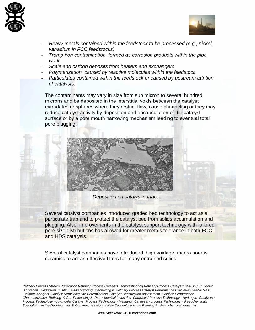
The contaminants may vary in size from sub micron to several hundred microns and be deposited in the interstitial voids between the catalyst extrudates or spheres where they restrict flow, cause channeling or they may reduce catalyst activity by deposition and encapsulation of the catalyst surface or by a pore mouth narrowing mechanism leading to eventual total pore plugging.
Deposition on catalyst surface
Several catalyst companies introduced graded bed technology to act as a particulate trap and to protect the catalyst bed from solids accumulation and plugging. Also, improvements in the catalyst support technology with tailored pore size distributions has allowed for greater metals tolerance in both FCC and HDS catalysis. Several catalyst companies have introduced, high voidage, macro porous ceramics to act as effective filters for many entrained solids.
Refinery Process Stream Purification Refinery Process Catalysts Troubleshooting Refinery Process Catalyst Start-Up / Shutdown Activation Reduction In-situ Ex-situ Sulfiding Specializing in Refinery Process Catalyst Performance Evaluation Heat & Mass Balance Analysis Catalyst Remaining Life Determination Catalyst Deactivation Assessment Catalyst Performance Characterization Refining & Gas Processing & Petrochemical Industries Catalysts / Process Technology - Hydrogen Catalysts / Process Technology – Ammonia Catalyst Process Technology - Methanol Catalysts / process Technology – Petrochemicals Specializing in the Development & Commercialization of New Technology in the Refining & Petrochemical Industries
Web Site: www.GBHEnterprises.com
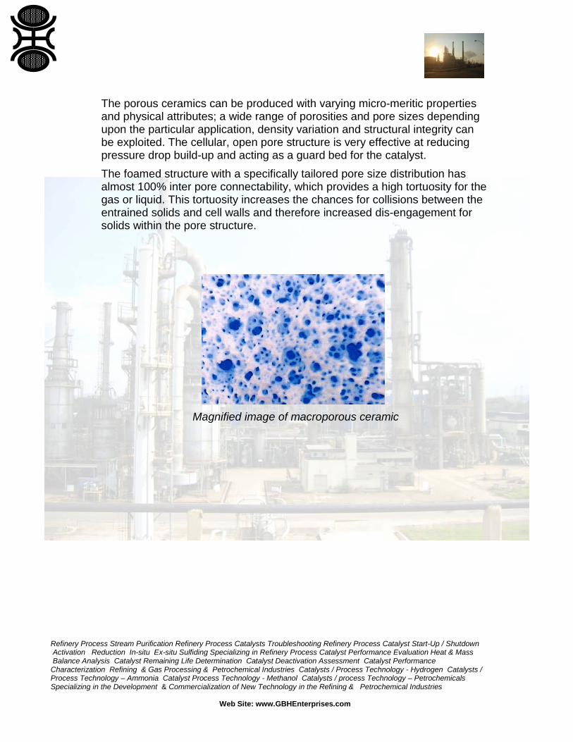
The porous ceramics can be produced with varying micro-meritic properties and physical attributes; a wide range of porosities and pore sizes depending upon the particular application, density variation and structural integrity can be exploited. The cellular, open pore structure is very effective at reducing pressure drop build-up and acting as a guard bed for the catalyst. The foamed structure with a specifically tailored pore size distribution has almost 100% inter pore connectability, which provides a high tortuosity for the gas or liquid. This tortuosity increases the chances for collisions between the entrained solids and cell walls and therefore increased dis-engagement for solids within the pore structure.
Magnified image of macroporous ceramic
Refinery Process Stream Purification Refinery Process Catalysts Troubleshooting Refinery Process Catalyst Start-Up / Shutdown Activation Reduction In-situ Ex-situ Sulfiding Specializing in Refinery Process Catalyst Performance Evaluation Heat & Mass Balance Analysis Catalyst Remaining Life Determination Catalyst Deactivation Assessment Catalyst Performance Characterization Refining & Gas Processing & Petrochemical Industries Catalysts / Process Technology - Hydrogen Catalysts / Process Technology – Ammonia Catalyst Process Technology - Methanol Catalysts / process Technology – Petrochemicals Specializing in the Development & Commercialization of New Technology in the Refining & Petrochemical Industries
Web Site: www.GBHEnterprises.com
The following notes are a broad description of the nature of carbon ‘coke’ deposits on high severity process catalysts such as Steam Reforming and HDS catalysts. The influence of catalyst and feedstock on the formation of carbon is described together with an overview of the ‘wave front’ technique for the removal of carbon using steam-oxygen (air) procedures. THE NATURE OF CARBON DEPOSITS FORMED ON CATALYSTS Carbon deposits formed on hydro processing or steam-reforming catalysts may be grouped into three broad types: A Fine, loose, ‘sooty’ type carbons. B Hard, ‘pitch-like’ polymeric carbons. C Hard, graphitic type carbons. Whilst the name ‘carbon’ is loosely applied to these deposits the term is strictly incorrect as all types of carbon found on catalysts contain low levels of chemically bonded hydrogen to the skeletal carbon structures. The carbon deposits are often, in reality, ultra high molecular weight hydrocarbons, which are formed via thermal-catalytic dehydrogenation (loss of hydrogen) of the feedstock components. Dehydrogenation reactions produce highly unsaturated – double bonded – hydrocarbon monomers that readily polymerize and further dehydrogenate to produce carbon rich deposits. Often a part of the ‘carbon’ deposit can be solubilized in solvents, indicating a hydrocarbon nature. The above types of carbon are often formed as amorphous or filamentous deposits on the catalyst surface. The filamentous type carbon deposits usually indicating operations at very low steam to carbon ratios with feeds containing high molecular weight hydrocarbons or from CO disproportionate through the Boudouard reaction, via the reaction mechanism 2CO C + CO2. The nature of the polymerized hydrocarbon ‘carbon’ deposit is very dependent upon the process operating conditions and the feedstock composition.
Refinery Process Stream Purification Refinery Process Catalysts Troubleshooting Refinery Process Catalyst Start-Up / Shutdown Activation Reduction In-situ Ex-situ Sulfiding Specializing in Refinery Process Catalyst Performance Evaluation Heat & Mass Balance Analysis Catalyst Remaining Life Determination Catalyst Deactivation Assessment Catalyst Performance Characterization Refining & Gas Processing & Petrochemical Industries Catalysts / Process Technology - Hydrogen Catalysts / Process Technology – Ammonia Catalyst Process Technology - Methanol Catalysts / process Technology – Petrochemicals Specializing in the Development & Commercialization of New Technology in the Refining & Petrochemical Industries
Web Site: www.GBHEnterprises.com
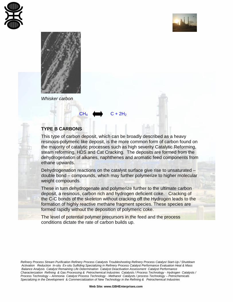
CARBON FORMATION Carbon deposits form by thermal and catalytic dehydrogenation of hydrocarbons on the catalyst surface or in the gas phase. The carbon forming mechanism is highly complex and encompasses both thermal cracking – breakage of C-C bonds and loss of hydrogen from one fragment; and catalytic dehydrogenation – loss of hydrogen without C-C bond scission reaction routes. The mechanisms are favored by high temperature (550-650oC), low hydrogen partial pressures, acidic catalysts and high molecular weight or unsaturated feed components. FEEDSTOCK COMPOSITION EFFECTS The composition of the feedstock used has a significant effect on the nature of the carbon deposit and therefore on the ease of carbon removal. TYPE A CARBONS Loose, sooty type A carbon deposits (whisker carbon) are generally found when processing low molecular weight feedstocks – such as a good quality Natural Gas. Except under exceptional circumstances pure methane will not form dehydrogenated species, which give rise to unsaturated monomers. Methane will not form a double bond on the single carbon atom, and hence dehydrogenation of methane leads to the deposition of single atom pure carbon species, which are readily removed in the steam reforming reaction under normal process conditions. If not removed by steam, the carbon forms loose agglomerates and is easily removed by oxidation in air. Carbon from methane does not normally lead to resinous-polymeric deposits. The methane decomposition reaction can be depicted by:
Refinery Process Stream Purification Refinery Process Catalysts Troubleshooting Refinery Process Catalyst Start-Up / Shutdown Activation Reduction In-situ Ex-situ Sulfiding Specializing in Refinery Process Catalyst Performance Evaluation Heat & Mass Balance Analysis Catalyst Remaining Life Determination Catalyst Deactivation Assessment Catalyst Performance Characterization Refining & Gas Processing & Petrochemical Industries Catalysts / Process Technology - Hydrogen Catalysts / Process Technology – Ammonia Catalyst Process Technology - Methanol Catalysts / process Technology – Petrochemicals Specializing in the Development & Commercialization of New Technology in the Refining & Petrochemical Industries
Web Site: www.GBHEnterprises.com
Whisker carbon CH4 C + 2H2 TYPE B CARBONS This type of carbon deposit, which can be broadly described as a heavy resinous-polymeric like deposit, is the more common form of carbon found on the majority of catalytic processes such as high severity Catalytic Reforming, steam reforming, HDS and Cat Cracking. The deposits are formed from the dehydrogenation of alkanes, naphthenes and aromatic feed components from ethane upwards. Dehydrogenation reactions on the catalyst surface give rise to unsaturated – double bond – compounds, which may further polymerize to higher molecular weight compounds. These in turn dehydrogenate and polymerize further to the ultimate carbon deposit, a resinous, carbon rich and hydrogen deficient coke. Cracking of the C-C bonds of the skeleton without cracking off the Hydrogen leads to the formation of highly reactive methane fragment species. These species are formed rapidly without the deposition of polymeric coke. The level of potential polymer precursors in the feed and the process conditions dictate the rate of carbon builds up.

Refinery Process Stream Purification Refinery Process Catalysts Troubleshooting Refinery Process Catalyst Start-Up / Shutdown Activation Reduction In-situ Ex-situ Sulfiding Specializing in Refinery Process Catalyst Performance Evaluation Heat & Mass Balance Analysis Catalyst Remaining Life Determination Catalyst Deactivation Assessment Catalyst Performance Characterization Refining & Gas Processing & Petrochemical Industries Catalysts / Process Technology - Hydrogen Catalysts / Process Technology – Ammonia Catalyst Process Technology - Methanol Catalysts / process Technology – Petrochemicals Specializing in the Development & Commercialization of New Technology in the Refining & Petrochemical Industries
Web Site: www.GBHEnterprises.com
dehydrogenation
H H H H
C = C—C—C—H + H2 Polymerization Coke
H H H H H H H
H--C—C—C—C--H
H H H H
Butane
If this type of carbon deposit is allowed to build up and is subjected to high temperatures over long periods it will further dehydrogenate, cyclize and form condensed ring, graphitic type C carbon. CnH2n+2 CnH2n +n H2 CnHn + H2 Aromatics + H2 Coke TYPE C CARBONS The hard, graphitic, unreactive type of carbon deposit generally derives from processing feedstocks, which contain significant levels of single and condensed aromatic ring hydrocarbons – Benzene and above. The aromatic type molecule is hydrogen deficient, by nature of the aromatic double bond structure, and is capable of further dehydrogenation and linking of aromatic rings to form multi-ring, graphitic form, hydrogen deficient carbon polymers. The graphitic forms of condensed ring aromatics are normally associated with high heat duty, hydrogen deficient processes. The deposits build up slowly with time on stream and are exceedingly difficult to remove even with full air oxidation techniques.
Desired pathway C+C+C+C
Undesired pathway
Refinery Process Stream Purification Refinery Process Catalysts Troubleshooting Refinery Process Catalyst Start-Up / Shutdown Activation Reduction In-situ Ex-situ Sulfiding Specializing in Refinery Process Catalyst Performance Evaluation Heat & Mass Balance Analysis Catalyst Remaining Life Determination Catalyst Deactivation Assessment Catalyst Performance Characterization Refining & Gas Processing & Petrochemical Industries Catalysts / Process Technology - Hydrogen Catalysts / Process Technology – Ammonia Catalyst Process Technology - Methanol Catalysts / process Technology – Petrochemicals Specializing in the Development & Commercialization of New Technology in the Refining & Petrochemical Industries
Web Site: www.GBHEnterprises.com
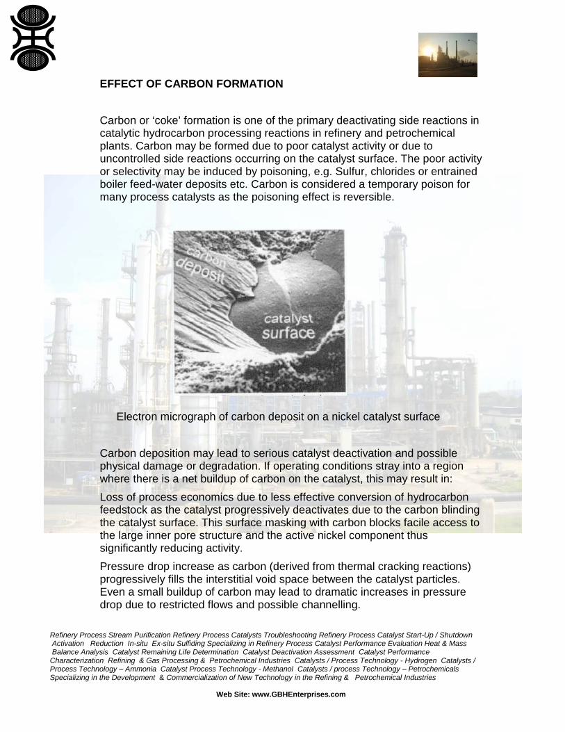
EFFECT OF CARBON FORMATION Carbon or ‘coke’ formation is one of the primary deactivating side reactions in catalytic hydrocarbon processing reactions in refinery and petrochemical plants. Carbon may be formed due to poor catalyst activity or due to uncontrolled side reactions occurring on the catalyst surface. The poor activity or selectivity may be induced by poisoning, e.g. Sulfur, chlorides or entrained boiler feed-water deposits etc. Carbon is considered a temporary poison for many process catalysts as the poisoning effect is reversible. Electron micrograph of carbon deposit on a nickel catalyst surface Carbon deposition may lead to serious catalyst deactivation and possible physical damage or degradation. If operating conditions stray into a region where there is a net buildup of carbon on the catalyst, this may result in: Loss of process economics due to less effective conversion of hydrocarbon feedstock as the catalyst progressively deactivates due to the carbon blinding the catalyst surface. This surface masking with carbon blocks facile access to the large inner pore structure and the active nickel component thus significantly reducing activity. Pressure drop increase as carbon (derived from thermal cracking reactions) progressively fills the interstitial void space between the catalyst particles. Even a small buildup of carbon may lead to dramatic increases in pressure drop due to restricted flows and possible channelling.
Refinery Process Stream Purification Refinery Process Catalysts Troubleshooting Refinery Process Catalyst Start-Up / Shutdown Activation Reduction In-situ Ex-situ Sulfiding Specializing in Refinery Process Catalyst Performance Evaluation Heat & Mass Balance Analysis Catalyst Remaining Life Determination Catalyst Deactivation Assessment Catalyst Performance Characterization Refining & Gas Processing & Petrochemical Industries Catalysts / Process Technology - Hydrogen Catalysts / Process Technology – Ammonia Catalyst Process Technology - Methanol Catalysts / process Technology – Petrochemicals Specializing in the Development & Commercialization of New Technology in the Refining & Petrochemical Industries
Web Site: www.GBHEnterprises.com
Pressure drops increase from catalyst breakage due to carbon formation (derived from polymerization reactions or from the Boudouard reaction) within the catalyst particle pore structure. These processes may occur gradually if operating conditions have only just moved into net carbon formation or may occur almost instantaneously if an incident leads, for example, to a slug of liquid hydrocarbon hitting the catalyst. Catalysts are often supported on ceramic carriers such as alumina, calcium or magnesium aluminates. These refractory carriers are insulators and are prone to damage by both thermal shocks and induced thermal stresses. All refractory materials suffer from micro-cracks formed during the initial manufacturing process. This makes the carriers susceptible to induced thermal stresses that can cause eventual failure though a classic brittle fracture mechanism. Steaming or steam/ air decokes therefore need to be carefully controlled to avoid excessive temperature gradients across the catalyst pellets that may propagate crack formation and eventually catastrophic catalyst failure. Once cracking is initiated, under heating or cooling transients, the cracking is extended under repetitive thermal cycling. This means it is imperative to operate the catalyst under steady state conditions, and to avoid carbon deposition or poisoning, if a long service life is to be achieved. ‘COMMERCIAL’ CARBON DEPOSITS In reality the nature of the carbon deposits on a commercial catalyst cannot be broken down into easily defined groups and the actual deposits are complex mixtures of all types of carbon polymer. It is however important to understand how the carbon deposits will react to oxidative removal and the possible upset conditions that may occur before embarking on carbon removal. Loss of control over the oxidative carbon burn or insufficient carbon removal will lead to catalyst and possible hardware damage or loss of throughput due to poorly regenerated catalyst.
Refinery Process Stream Purification Refinery Process Catalysts Troubleshooting Refinery Process Catalyst Start-Up / Shutdown Activation Reduction In-situ Ex-situ Sulfiding Specializing in Refinery Process Catalyst Performance Evaluation Heat & Mass Balance Analysis Catalyst Remaining Life Determination Catalyst Deactivation Assessment Catalyst Performance Characterization Refining & Gas Processing & Petrochemical Industries Catalysts / Process Technology - Hydrogen Catalysts / Process Technology – Ammonia Catalyst Process Technology - Methanol Catalysts / process Technology – Petrochemicals Specializing in the Development & Commercialization of New Technology in the Refining & Petrochemical Industries
Web Site: www.GBHEnterprises.com
Dependent on the nature of the process, the feedstock and the catalyst, the deposited carbon will range from the sooty, easily burnt, to the graphitic, unreactive carbon. Those processes operating with light feeds at low severity – i.e. naphtha HDS – will have a significant amount of light, easily burnt off carbon, at the end of the cycle life. A steam reformer processing naphtha or natural gas with heavy end components, which has suffered a low steam to carbon operation over a prolonged period, or a unit with aromatic or heavy aliphatic feed contaminants; will produce a significant amount of graphitic and resinous carbon. The naphtha hydrotreater will be able to be regenerated easily at low temperature with low oxygen levels whereas the steam reformer will require higher temperatures and oxygen levels to remove the carbon. The requirements of temperature and oxygen cannot be prejudged prior to regeneration (as normally samples of the carbon are not available) and therefore each regeneration carried out is unique and liable to upset unless adequately monitored and controlled. Reactor size and catalyst volume are important considerations – it is easier to control the burning of carbon coated catalyst in a 100mm diameter steam reformer tube than in a 2 m diameter x 4 m carbon coated HDS catalyst loaded reactor. CARBON BURNING IN AIR Examination of the ignition temperatures of varying molecular weights of carbon polymers ‘carbons’ in pure air shows an almost linear graph of temperature with carbon number. That is the light carbons burn first and graphite last. Broadly a light carbon deposit will start to burn in air from 300oC and the graphitic type carbon from 580oC to as high as 680oC in air. The oxidative burning of carbon is highly exothermic, with potential temperatures in excess of 1000oC produced at the point of carbon burn. When a mixture of light carbon ‘soot’ and graphite is heated in air to a temperature at which the ‘soot’ begins to burn, but below that temperature at which the graphite normally burns, it is found that both ‘soot’ and graphite burn. The exotherm from soot burning is sufficient to raise the temperature to above that required to pyrolyze the graphite and both forms of carbon are removed by the runaway exotherm.
Refinery Process Stream Purification Refinery Process Catalysts Troubleshooting Refinery Process Catalyst Start-Up / Shutdown Activation Reduction In-situ Ex-situ Sulfiding Specializing in Refinery Process Catalyst Performance Evaluation Heat & Mass Balance Analysis Catalyst Remaining Life Determination Catalyst Deactivation Assessment Catalyst Performance Characterization Refining & Gas Processing & Petrochemical Industries Catalysts / Process Technology - Hydrogen Catalysts / Process Technology – Ammonia Catalyst Process Technology - Methanol Catalysts / process Technology – Petrochemicals Specializing in the Development & Commercialization of New Technology in the Refining & Petrochemical Industries
Web Site: www.GBHEnterprises.com
Removing the potential for graphite burning is only achieved by removing the source of oxygen. Reduction of the temperature, whilst retaining the oxygen level will not be sufficient to stop gross carbon burning. This summarizes the basis of the regeneration procedure commonly used in a wide variety of catalytic hydrocarbon processing reactors employing the wave front technique. Regeneration of carbonized catalysts by heating the catalyst in an inert atmosphere, up to or above the temperature at which the light carbon burns, and then introducing an initial pulse of low level of oxygen is an established commercial procedure. The procedure allows an oxygen and carbon burn wave front to move, in a controlled manner, through the catalyst bed. If the oxygen level is low enough on the first burn, the exotherm – which is a function of the rate of carbon burn – will not be sufficient to substantially increase the surface temperature and therefore uncontrolled burning does not take place. The technique allows the carbon to be removed by burning off layers of carbon in steadily increasing levels of oxygen. CARBON REMOVAL BY STEAMING Steaming is a recognized procedure for decoking catalysts. The method is simple and does not have the potential risks associated with oxygen decoking – i.e. over burn and runaway exotherms. Steaming however is only suitable for the light/medium type of carbon deposits, which are readily gasified on the catalyst surface by low temperature steam in conjunction with the catalyst nickel component. With the heavier and graphitic types of carbon the rate of removal by steam is too slow to make this method attractive. The catalyst surface composition plays a more significant part in catalyzing carbon removal by steam than it does when using the oxygen removal procedure. Additions of alkali, such as potash, to the catalyst composition enhance the rate of carbon removal, as does a high intrinsic metal dispersion. In those cases where the carbon deposition is judged to be ‘light’ i.e. of recent origin and from a clean feed, steaming is an adequate and effective method to remove carbon. In those cases where the deposits are ‘hard’ – old and from a feedstock containing high molecular weight or aromatic components, steaming will not be an adequate means of removing the carbon case.
Refinery Process Stream Purification Refinery Process Catalysts Troubleshooting Refinery Process Catalyst Start-Up / Shutdown Activation Reduction In-situ Ex-situ Sulfiding Specializing in Refinery Process Catalyst Performance Evaluation Heat & Mass Balance Analysis Catalyst Remaining Life Determination Catalyst Deactivation Assessment Catalyst Performance Characterization Refining & Gas Processing & Petrochemical Industries Catalysts / Process Technology - Hydrogen Catalysts / Process Technology – Ammonia Catalyst Process Technology - Methanol Catalysts / process Technology – Petrochemicals Specializing in the Development & Commercialization of New Technology in the Refining & Petrochemical Industries
Web Site: www.GBHEnterprises.com
CARBON BURN CONTROL METHODS Regeneration of a carbon coated HDS catalyst in a reactor of dimensions 2m dia x 4m ht is extremely hazardous. Due to the bulk compacted bed of catalyst a runaway exotherm is unavoidable without the correct controls on the regeneration. Without adequate oxygen control, temperatures of 1200oC have been observed and the catalyst fuses into inert lumps. HDS catalyst regenerations are however carried out on a routine basis, both in situ and ex situ, without catalyst damage. Oxygen analyzers and temperature indicators at the inlet, in the catalyst bed and exit the reactor are used to indicate the inlet oxygen and the temperature of the burn wave. In the case of the multi-tube steam reformer, temperature indication of the burn is not a viable control option. This is due to the mode of process heating and the amount of carbon burnt per tube per wave would not be sufficient to increase the temperature by a significant value. If the tubes glow during the burn, the regeneration has been uncontrolled and catalyst damage will result. There is only one control procedure to be recommended for regenerating a catalyst – monitor the exit carbon dioxide with a carbon dioxide meter (must be infra red) coupled to a chart recorder. The chart recorder will give an immediate trend line when the carbon commences burning. The carbon dioxide meter should read 0-5% to obtain the required accuracy. Drager tubes and Orsat are not recommended, as they are neither accurate enough nor capable of continuously monitoring the exit gas streams. Oxygen inlet analysis cannot be used when the diluent is steam and therefore the rate of oxygen (air) addition must be controlled by means of a readily accessible and controllable air inlet valve. Inlet oxygen analyzers should be used when the diluent is inert gas. CATALYST – REACTION WITH STEAM Typically steam is used as the inert diluent during the regeneration of steam reforming catalysts. Using the regeneration procedures outlined below, steam will not have a detrimental effect on the catalyst, as the temperatures will be maintained within the operating envelope of the catalyst in steam. However, if the catalyst is steamed at temperatures significantly higher than normal operating temperatures the structure of the catalyst may be changed in such a way that will reduce the reforming activity (metal agglomeration and sintering). High temperature steaming increases the time required to fully re-reduce the catalyst once returned to an on- stream condition.
Refinery Process Stream Purification Refinery Process Catalysts Troubleshooting Refinery Process Catalyst Start-Up / Shutdown Activation Reduction In-situ Ex-situ Sulfiding Specializing in Refinery Process Catalyst Performance Evaluation Heat & Mass Balance Analysis Catalyst Remaining Life Determination Catalyst Deactivation Assessment Catalyst Performance Characterization Refining & Gas Processing & Petrochemical Industries Catalysts / Process Technology - Hydrogen Catalysts / Process Technology – Ammonia Catalyst Process Technology - Methanol Catalysts / process Technology – Petrochemicals Specializing in the Development & Commercialization of New Technology in the Refining & Petrochemical Industries
Web Site: www.GBHEnterprises.com
Similarly, high temperatures in an oxidizing atmosphere will reduce the activity by sintering the active nickel phase and produce a less easily reducible catalyst. High temperatures in steam and oxygen are to be avoided at all times. Temperatures within the normal process-operating envelope will not deactivate the catalyst: Low steam flow-high heat fluxes will rapidly deactivate the catalyst. Steam contact with the catalyst surface at the point of carbon burn will not deactivate the catalyst if the burn exotherm is correctly controlled. MAXIMUM OXYGEN CONCENTRATION There is not a maximum oxygen level above which the catalyst cannot be exposed – only a maximum temperature. The catalyst should not be exposed to temperatures higher than 650oC in a pure air stream for extended periods. ‘With lower oxygen concentrations the temperature can be allowed to go up to 700oC in 5% oxygen for extended periods. TEMPERATURE OF THE CATALYST SURFACE DURING CARBON BURNS With the correct control of the regeneration conditions, and an even carbon burn, the surface of the catalyst will not substantially rise above that of the process gas or steam flow. In cases where the carbon burn front is allowed to burn in a high of an uncontrolled oxygen level the surface temperature of the catalyst will rise substantially, resulting in sintering and agglomeration of the active metal phase. The immediate catalyst surface and pore internals will be subjected to localized over-heating but this increase will not normally be noted in the exit gas temperature and the overheating will result in catalyst breakdown and subsequent high pressure drop.
Refinery Process Stream Purification Refinery Process Catalysts Troubleshooting Refinery Process Catalyst Start-Up / Shutdown Activation Reduction In-situ Ex-situ Sulfiding Specializing in Refinery Process Catalyst Performance Evaluation Heat & Mass Balance Analysis Catalyst Remaining Life Determination Catalyst Deactivation Assessment Catalyst Performance Characterization Refining & Gas Processing & Petrochemical Industries Catalysts / Process Technology - Hydrogen Catalysts / Process Technology – Ammonia Catalyst Process Technology - Methanol Catalysts / process Technology – Petrochemicals Specializing in the Development & Commercialization of New Technology in the Refining & Petrochemical Industries
Web Site: www.GBHEnterprises.com
CONDITIONS TO BURN OFF CARBON COATED CATALYST The oxidative (air) burning of carbon is the recommended method to use for the removal of carbon deposits. However the method should only be used if the correct analysis equipment is available and correct control of the air volumes can be maintained.