measurements of fundamental properties of homogeneous tissue phantoms
TRANSCRIPT

Measurements of fundamentalproperties of homogeneous tissuephantoms
Maciej S. WróbelAlexey P. PopovAlexander V. BykovMatti KinnunenMalgorzata Jedrzejewska-SzczerskaValery V. Tuchin
Downloaded From: http://biomedicaloptics.spiedigitallibrary.org/ on 04/20/2015 Terms of Use: http://spiedl.org/terms

Measurements of fundamental properties ofhomogeneous tissue phantoms
Maciej S. Wróbel,a,* Alexey P. Popov,b Alexander V. Bykov,b Matti Kinnunen,b
Malgorzata Jedrzejewska-Szczerska,a and Valery V. Tuchinb,c,d
aGdańsk University of Technology, Faculty of Electronics, Telecommunications and Informatics, Department of Metrology and Optoelectronics,Gabriela Narutowicza Street 11/12, 80-233 Gdańsk, PolandbUniversity of Oulu, Faculty of Information Technology and Electrical Engineering, Optoelectronics and Measurement Techniques Laboratory,P.O. Box 4500, Oulu 90014, FinlandcSaratov State University, Research-Educational Institute of Optics and Biophotonics, Saratov 410012, RussiadInstitute of Precise Mechanics and Control of Russian Academy of Sciences, Saratov 410028, Russia
Abstract. We present the optical measurement techniques used in human skin phantom studies. Their accuracyand the sources of errors in microscopic parameters’ estimation of the produced phantoms are described. Wehave produced optical phantoms for the purpose of simulating human skin tissue at the wavelength of 930 nm.Optical coherence tomography was used to measure the thickness and surface roughness and to detectthe internal inhomogeneities. A more detailed study of phantom surface roughness was carried out with theoptical profilometer. Reflectance, transmittance, and collimated transmittance of phantoms were measuredusing an integrating-sphere spectrometer setup. The scattering and absorption coefficients were calculatedwith the inverse adding-doubling method. The reduced scattering coefficient at 930 nm was found to be 1.57�0.14 mm−1 and the absorption was 0.22� 0.03 mm−1. The retrieved optical properties of phantoms are in agree-ment with the data found in the literature for real human tissues. © The Authors. Published by SPIE under a Creative Commons
Attribution 3.0 Unported License. Distribution or reproduction of this work in whole or in part requires full attribution of the original publication, including its
DOI. [DOI: 10.1117/1.JBO.20.4.045004]
Keywords: tissue-mimicking phantoms; optical phantoms; optical properties; skin; spectrophotometry; scattering.
Paper 150095R received Feb. 19, 2015; accepted for publication Mar. 18, 2015; published online Apr. 17, 2015.
1 Introduction
The emergence of new optical measurement techniques in thefield of biophotonics has increased the interest in the possibilityof their use for medically relevant, noninvasive in vivo imaging
and measurements.1–10 The development and evaluation of suchmethods require frequent calibration of the devices. However,real biological tissues differ greatly from each other and theiroptical properties are susceptible to rapid changes over timeand with varying environmental conditions.11–14 This calls for
the development of substitutes of specific biological tissues,which are optical tissue-mimicking phantoms.15–18 One type ofphantom is composed of solid flexible materials with addedscattering and absorbing particles suspended in a transparent
matrix material. To assure phantoms as a valid and reliable stan-dard for noninvasive optical diagnostic techniques,16–20 theiroptical properties must be precisely measured and controlledby the fabrication process.21–26
The scattering, absorption, and scattering anisotropy are thefundamental microscopic properties that describe the photonmigration in a turbid medium, such as tissues;27,28 thus, thedesign and production processes of tissue phantoms focus ontheir exact matching. These microscopic properties can be mea-
sured indirectly by measuring macroscopic parameters, suchas reflectance or transmittance, and by applying a model oflight propagation.29 The inverse adding-doubling (IAD) methodcan be used to calculate the coefficients of the sample from
reflectance, transmittance, and collimated transmittance mea-surements.30,31 This method relies on the iterative solving ofthe radiative transport equation with the adding-doublingmethod and yields the absorption and scattering coefficients,as well as the anisotropy factor. The sample is assumed to bean infinite plane-parallel slab with known thickness and refrac-tive index (RI). The optical properties of the sample are assumedto be uniform. IAD has been proven to provide results relativelyquickly with a relative error of 2% to 3%. It has been reportedthat the errors in retrieval of the optical properties of a materialare roughly one level of magnitude larger, due to measurements,than the method itself.31 Therefore, proper measurements are ofthe utmost importance due to their use as input parameters inthe IAD method.
The purpose of this paper is the production and characteri-zation of a series of phantoms with different thicknesses as validsubstitutes for biological samples (human skin) for noninvasivediagnostic methods, with their potential use in medicine. Wepresent a variety of optical measurement techniques, which wereused for reconstruction of the most important properties ofphantoms. Measured parameters include the optical properties,geometry, and surface roughness.
2 Phantom Fabrication Process
Phantoms used in this study mimic human skin at the centralwavelength of 930 nm, common for optical coherence tomog-raphy (OCT) devices. The scattering properties were modeledon the basis of the Mie theory and known optical propertiesof the constituent materials.32–35 One series of scattering andnonabsorbing phantoms with variable thickness from 200 μm
*Address all correspondence to: Maciej S. Wróbel, E-mail: maciejswrobel@
gmail.com
Journal of Biomedical Optics 045004-1 April 2015 • Vol. 20(4)
Journal of Biomedical Optics 20(4), 045004 (April 2015)
Downloaded From: http://biomedicaloptics.spiedigitallibrary.org/ on 04/20/2015 Terms of Use: http://spiedl.org/terms
up to 2 mm was produced. Additional absorption was intro-duced to the second series of phantoms with the same scatteringand thickness as the previous series. The phantoms were madeusing zinc oxide (ZnO) nanoparticles as a scattering agent,the matrix material, and an absorbing substance. A polyvinylchloride-plastisol (PVCP) two-component stock solution (M-FManufacturing Co., Fort Worth, Texas) was used as a matrixmaterial for the phantom fabrication. PVCP has a RI of 1.44(at 930 nm) and becomes transparent due to polymerizationafter curing at a high temperature. The desired scattering wasobtained using ZnO nanoparticles powder (Sigma-Aldrich,Germany) with an average size of 340 nm. PVCP solution wasthoroughly mixed with ZnO to ensure homogenous distribution.For the absorbing phantoms, a 0.1% [v/v] amount of ink wasadded to the mixture. The mixture was sonicated for 15 minto destroy particle clusters and to evenly distribute the particlesin the suspension. It was then poured into plane rectangularmolds with different thicknesses and degassed to removetrapped air bubbles. The phantoms solidified after heating at180°C for 1 h.
3 Fundamental Parameters of TissuePhantoms
The absorption coefficient μa describes the attenuation of lightdue to absorption by the medium at a certain wavelength. Thisparameter of skin phantoms depends on concentration ofabsorbers in skin, mainly melanin and hemoglobin. The reducedscattering coefficient μ 0
s describes the photon migration process intissues in the diffuse regime.16 The anisotropy factor g (a meancosine of the scattering angle) allows for calculation of thescattering coefficient μs, according to the equation:
μs ¼μ 0s
1 − g; (1)
which fully describes the scattering properties of the material.27–31
To estimate the value of μs, it is necessary to measure the trans-mittance of the collimated light from the investigated samples.Precise matching of these parameters of phantoms and biotissuesis crucial for producing reliable phantoms. The optical signalresponse of a phantom is then identical to that of a tissue makingit valid for instrument calibration.7–9,36–39 Therefore, the exactreconstruction of the scattering and absorption may be performedbased only on accurate measurements. We estimated the coeffi-cients μa, μ
0s, and g for each phantom using spectrometric mea-
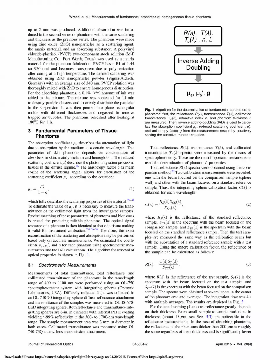
surements and the IAD calculations. The algorithm for retrieval ofoptical properties is shown in Fig. 1.
3.1 Spectrometric Measurements
Measurements of total transmittance, total reflectance, andcollimated transmittance of the phantoms in the wavelengthrange of 400 to 1100 nm were performed using an OL-750spectrophotometer system with integrating spheres (OptronicLaboratories, USA). Diffusely reflected light was collected inan OL 740-70 integrating sphere diffuse reflectance attachmentand transmittance of the samples was measured in OL IS-670-LED integrating sphere. Both reflectance and transmittance inte-grating spheres are 6-in. in diameter with internal PTFE coatingyielding >99% reflectivity in the 300- to 1700-nm wavelengthrange. The sample measurement area was 3 mm in diameter inboth cases. Collimated transmittance was measured using OL740-73Q quartz lens transmission attachment.
Total reflectance RðλÞ, transmittance TðλÞ, and collimated
transmittance TcðλÞ spectra were measured by the means of
spectrophotometry. These are the most important measurements
used for determination of phantoms’ properties.Total reflectance RðλÞ spectra were obtained using the com-
parison method.30 Two calibration measurements were recorded,
one with the beam focused on the comparison sample (sphere
wall) and other with the beam focused on a standard reference
sample. Thus, the integrating sphere calibration factor CðλÞ isobtained for each wavelength:
CðλÞ ¼RSðλÞSCSðλÞ
SSRðλÞ; (2)
where RSðλÞ is the reflectance of the standard reflectance
sample, SCSðλÞ is the spectrum with the beam focused on the
comparison sample, and SSRðλÞ is the spectrum with the beam
focused on the standard reflectance sample. Then the test sam-
ples are measured the same way as the calibration scans but
with the substitution of a standard reference sample with a test
sample. Using the sphere calibration factor, the reflectance of
the sample can be calculated as follows:
RðλÞ ¼CðλÞSTðλÞ
SCTðλÞ; (3)
where RðλÞ is the reflectance of the test sample, STðλÞ is the
spectrum with the beam focused on the test sample, and
SCTðλÞ is the spectrum with the beam focused on the comparison
sample. The spectra were obtained at several spots in the center
of the phantom area and averaged. The integration time was 4 s
with multiple averages. The results are depicted in Fig. 2.For the nonabsorbing phantoms, reflectance greatly depends
on their thickness. Even small sample-to-sample variations in
thickness (about 15 μm, see Sec. 3.3) are noticeable in the
reflectance measurements. In the case of absorbing phantoms,
the reflectance of the phantoms thicker than 200 μm is roughly
the same regardless of their thickness and is significantly lower
Fig. 1 Algorithm for the determination of fundamental parameters ofphantoms: first, the reflectance RðλÞ, transmittance T ðλÞ, collimatedtransmittance T cðλÞ, refractive index n, and phantom thickness L
are measured. Then, inverse adding-doubling (IAD) is used to calcu-late the absorption coefficient μa, reduced scattering coefficient μ 0
s ,and anisotropy factor g from the measurement results by iterativelysolving the radiative transfer equation.
Journal of Biomedical Optics 045004-2 April 2015 • Vol. 20(4)
Wróbel et al.: Measurements of fundamental properties of homogeneous tissue phantoms
Downloaded From: http://biomedicaloptics.spiedigitallibrary.org/ on 04/20/2015 Terms of Use: http://spiedl.org/terms
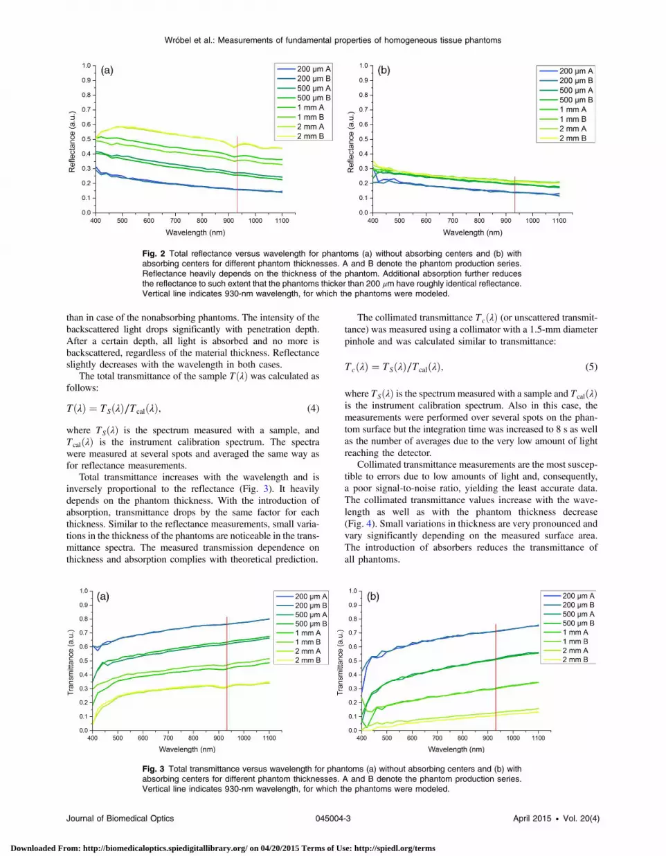
than in case of the nonabsorbing phantoms. The intensity of the
backscattered light drops significantly with penetration depth.
After a certain depth, all light is absorbed and no more is
backscattered, regardless of the material thickness. Reflectance
slightly decreases with the wavelength in both cases.The total transmittance of the sample TðλÞ was calculated as
follows:
TðλÞ ¼ TSðλÞ∕TcalðλÞ; (4)
where TSðλÞ is the spectrum measured with a sample, and
TcalðλÞ is the instrument calibration spectrum. The spectra
were measured at several spots and averaged the same way as
for reflectance measurements.Total transmittance increases with the wavelength and is
inversely proportional to the reflectance (Fig. 3). It heavily
depends on the phantom thickness. With the introduction of
absorption, transmittance drops by the same factor for each
thickness. Similar to the reflectance measurements, small varia-
tions in the thickness of the phantoms are noticeable in the trans-
mittance spectra. The measured transmission dependence on
thickness and absorption complies with theoretical prediction.
The collimated transmittance TcðλÞ (or unscattered transmit-
tance) was measured using a collimator with a 1.5-mm diameter
pinhole and was calculated similar to transmittance:
TcðλÞ ¼ TSðλÞ∕TcalðλÞ; (5)
where TSðλÞ is the spectrum measured with a sample and TcalðλÞis the instrument calibration spectrum. Also in this case, the
measurements were performed over several spots on the phan-
tom surface but the integration time was increased to 8 s as well
as the number of averages due to the very low amount of light
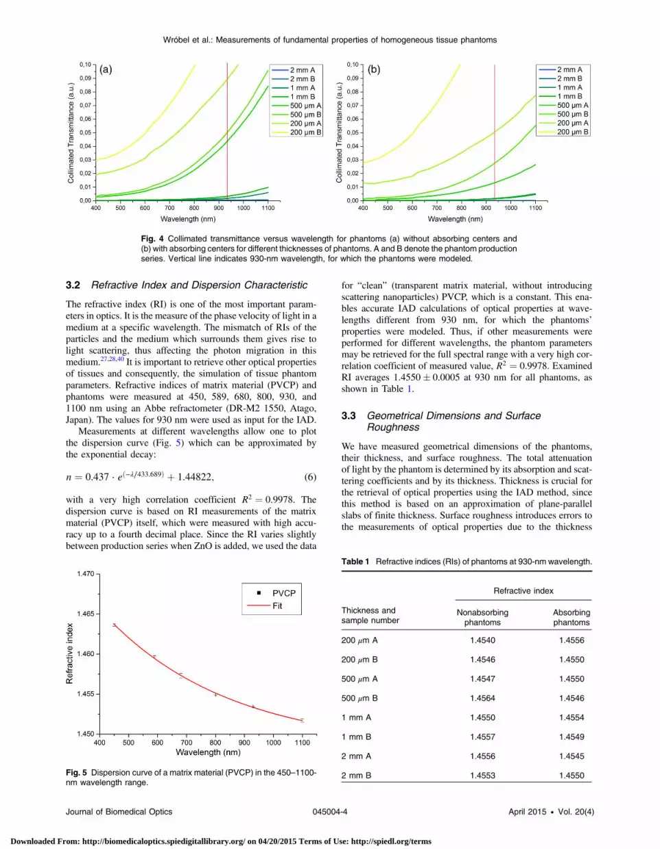
reaching the detector.Collimated transmittance measurements are the most suscep-
tible to errors due to low amounts of light and, consequently,
a poor signal-to-noise ratio, yielding the least accurate data.
The collimated transmittance values increase with the wave-
length as well as with the phantom thickness decrease
(Fig. 4). Small variations in thickness are very pronounced and
vary significantly depending on the measured surface area.
The introduction of absorbers reduces the transmittance of
all phantoms.
Fig. 2 Total reflectance versus wavelength for phantoms (a) without absorbing centers and (b) withabsorbing centers for different phantom thicknesses. A and B denote the phantom production series.Reflectance heavily depends on the thickness of the phantom. Additional absorption further reducesthe reflectance to such extent that the phantoms thicker than 200 μm have roughly identical reflectance.Vertical line indicates 930-nm wavelength, for which the phantoms were modeled.
Fig. 3 Total transmittance versus wavelength for phantoms (a) without absorbing centers and (b) withabsorbing centers for different phantom thicknesses. A and B denote the phantom production series.Vertical line indicates 930-nm wavelength, for which the phantoms were modeled.
Journal of Biomedical Optics 045004-3 April 2015 • Vol. 20(4)
Wróbel et al.: Measurements of fundamental properties of homogeneous tissue phantoms
Downloaded From: http://biomedicaloptics.spiedigitallibrary.org/ on 04/20/2015 Terms of Use: http://spiedl.org/terms
3.2 Refractive Index and Dispersion Characteristic
The refractive index (RI) is one of the most important param-eters in optics. It is the measure of the phase velocity of light in a
medium at a specific wavelength. The mismatch of RIs of theparticles and the medium which surrounds them gives rise to
light scattering, thus affecting the photon migration in thismedium.27,28,40 It is important to retrieve other optical propertiesof tissues and consequently, the simulation of tissue phantom
parameters. Refractive indices of matrix material (PVCP) andphantoms were measured at 450, 589, 680, 800, 930, and
1100 nm using an Abbe refractometer (DR-M2 1550, Atago,Japan). The values for 930 nm were used as input for the IAD.
Measurements at different wavelengths allow one to plot
the dispersion curve (Fig. 5) which can be approximated bythe exponential decay:
n ¼ 0.437 · eð−λ∕433.689Þ þ 1.44822; (6)
with a very high correlation coefficient R2 ¼ 0.9978. The
dispersion curve is based on RI measurements of the matrixmaterial (PVCP) itself, which were measured with high accu-
racy up to a fourth decimal place. Since the RI varies slightlybetween production series when ZnO is added, we used the data
for “clean” (transparent matrix material, without introducingscattering nanoparticles) PVCP, which is a constant. This ena-bles accurate IAD calculations of optical properties at wave-lengths different from 930 nm, for which the phantoms’properties were modeled. Thus, if other measurements wereperformed for different wavelengths, the phantom parametersmay be retrieved for the full spectral range with a very high cor-relation coefficient of measured value, R2 ¼ 0.9978. ExaminedRI averages 1.4550� 0.0005 at 930 nm for all phantoms, asshown in Table 1.
3.3 Geometrical Dimensions and SurfaceRoughness
We have measured geometrical dimensions of the phantoms,their thickness, and surface roughness. The total attenuationof light by the phantom is determined by its absorption and scat-tering coefficients and by its thickness. Thickness is crucial forthe retrieval of optical properties using the IAD method, sincethis method is based on an approximation of plane-parallelslabs of finite thickness. Surface roughness introduces errors tothe measurements of optical properties due to the thickness
Fig. 4 Collimated transmittance versus wavelength for phantoms (a) without absorbing centers and(b) with absorbing centers for different thicknesses of phantoms. A and B denote the phantom productionseries. Vertical line indicates 930-nm wavelength, for which the phantoms were modeled.
Fig. 5 Dispersion curve of a matrix material (PVCP) in the 450–1100-nm wavelength range.
Table 1 Refractive indices (RIs) of phantoms at 930-nm wavelength.
Thickness andsample number
Refractive index
Nonabsorbingphantoms
Absorbingphantoms
200 μm A 1.4540 1.4556
200 μm B 1.4546 1.4550
500 μm A 1.4547 1.4550
500 μm B 1.4564 1.4546
1 mm A 1.4550 1.4554
1 mm B 1.4557 1.4549
2 mm A 1.4556 1.4545
2 mm B 1.4553 1.4550
Journal of Biomedical Optics 045004-4 April 2015 • Vol. 20(4)
Wróbel et al.: Measurements of fundamental properties of homogeneous tissue phantoms
Downloaded From: http://biomedicaloptics.spiedigitallibrary.org/ on 04/20/2015 Terms of Use: http://spiedl.org/terms
variation and the results of the following calculations, because a
smooth homogeneous surface is assumed by IAD. The magni-
tude of errors in reconstruction of the phantom optical properties
is due to surface roughness and the thickness measurement
precision.A spectral-domain OCT system (Hyperion, Thorlabs, USA)
was used for retrieval of the phantom geometrical thickness.
OCT depends on the interference of low-coherent light from
measurement and sensing arms of the interferometer, thus it
is sensitive to the thickness and the RI of a sample.41–43 For
the measurements, the phantoms were placed on a glass slide.
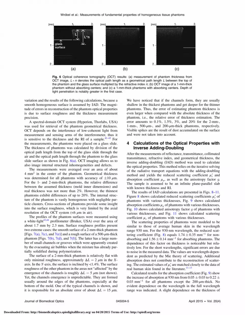
The thickness of phantoms was calculated by division of the
optical path length from the top of the glass slide through the
air and the optical path length through the phantom to the glass
slide surface as shown in Fig. 6(a). OCT imaging allows us to
also image internal structural inhomogeneities and defects.The measurements were averaged over an area of about
4 mm2 in the center of the phantom. Geometrical thickness
was determined for all phantoms with accuracy of �10 μm.
For the 1- and 2-mm-thick phantoms, the relative difference
between the assumed thickness (mold inner dimensions) and
real thickness was not more than 2%. However, the thinnest
phantoms exhibit differences of up to 20%. The internal struc-
ture of the phantom is vastly homogenous with negligible par-
ticle clusters. Cross-sections of phantoms provide some insight
into the surface roughness, which is very limited by the axial
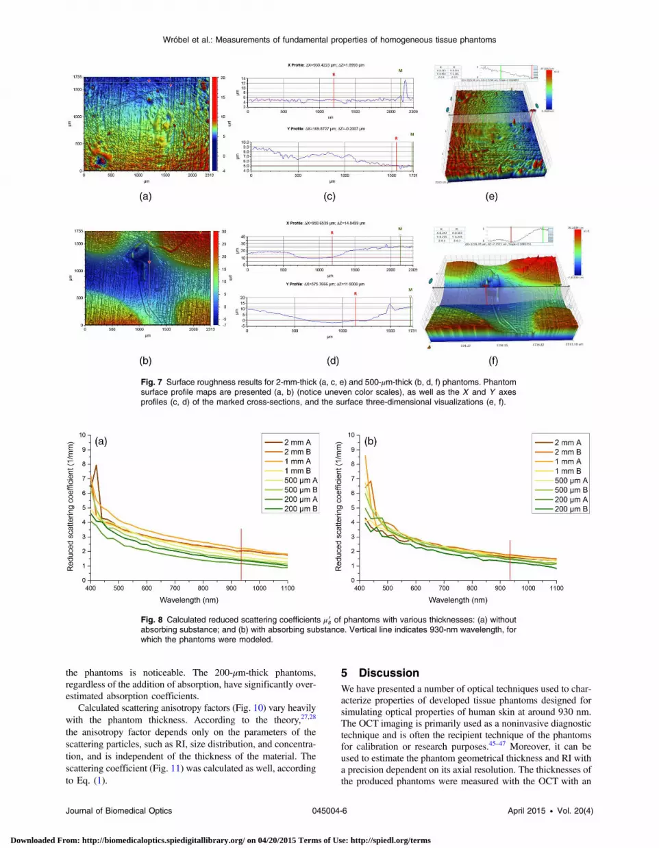
resolution of the OCT system (<6 μm in air).The profiles of the phantom surfaces were measured using
a white-light43,44 profilometer (Bruker, USA) over the area of
about 1.7 mm by 2.3 mm. Surface roughness profiles present
two extreme cases: the smooth surface of a 2-mm-thick phantom
[Figs. 7(a), 7(c), and 7(e)] and a rough surface of a 500-μm-thick
phantom [Figs. 7(b), 7(d), and 7(f)]. The latter has a large num-
ber of small channels or grooves which were apparently created
by the evacuating air bubbles when the mixture has already par-
tially solidified during polymerization.The surface of a 2-mm-thick phantom is relatively flat with
only minimal roughness, approximately ΔL ¼ 2 μm in the X-
axis. In the Y-axis, the surface is inclined by <1.4%. The surface
roughness of the other phantom in the areas not “affected” by the
emergence of the channels is roughly ΔL ¼ 5 μm (not shown).
Yet, the channels emergence is unpredictable. They are formed
usually around the edges of the phantoms, especially at the
bottom of the mold. One of the typical channels is shown, and
it is responsible for an absolute error of about ΔL ¼ 15 μm.
We have noticed that if the channels form, they are usuallyshallow in the thickest phantoms and get deeper for the thinnerphantoms. Thus, the error of estimating phantom thickness iseven larger when compared with the absolute thickness of thephantom, i.e., the relative error of thickness estimation. Theerror amounts to 0.1%, 1.5%, 3%, and 20% for the 2-mm-,1-mm-, 500-μm-, and 200-μm-thick phantoms, respectively.Visible spikes are the result of dust accumulated on the surfaceand were not taken into account.
4 Calculations of the Optical Properties withInverse Adding-Doubling
After the measurements of reflectance, transmittance, collimatedtransmittance, refractive index, and geometrical thickness, theinverse adding-doubling (IAD) method was used to calculatethe optical properties. This method relies on the iterative solvingof the radiative transport equations with the adding-doublingmethod and yields the reduced scattering coefficient μ 0
s andabsorption coefficient μa, as well as the anisotropy factor g.The sample is assumed to be an infinite plane-parallel slabwith known thickness and RI.
The results of IAD calculations are presented in Figs. 8–11.Figure 8 shows calculated reduced scattering coefficients μ 0
s ofphantoms with various thicknesses, Fig. 9 shows calculatedabsorption coefficients μa of phantoms with various thicknesses,Fig. 10 shows calculated anisotropy factor g of phantoms withvarious thicknesses, and Fig. 11 shows calculated scatteringcoefficient μs of phantoms with various thicknesses.
The scattering properties of phantoms were modeled to besimilar to those of average human skin in the wavelengthrange 930 nm. For the 930-nm wavelength, the reduced scat-tering coefficient (Fig. 8) equals 1.74� 0.35 mm−1 for non-absorbing and 1.56� 0.14 mm−1 for absorbing phantoms. Thedependence of this factor on thickness is noticeable but rela-tively low. For the short wavelengths, significant errors are dueto noise in the measured data. The values are wavelength-depen-dent as predicted by the Mie theory of scattering. Additionalabsorption does not contribute to the reconstruction of scatter-ing. The estimated values of μ 0
s are matched closely to the data ofreal human skin found in the literature.11–13
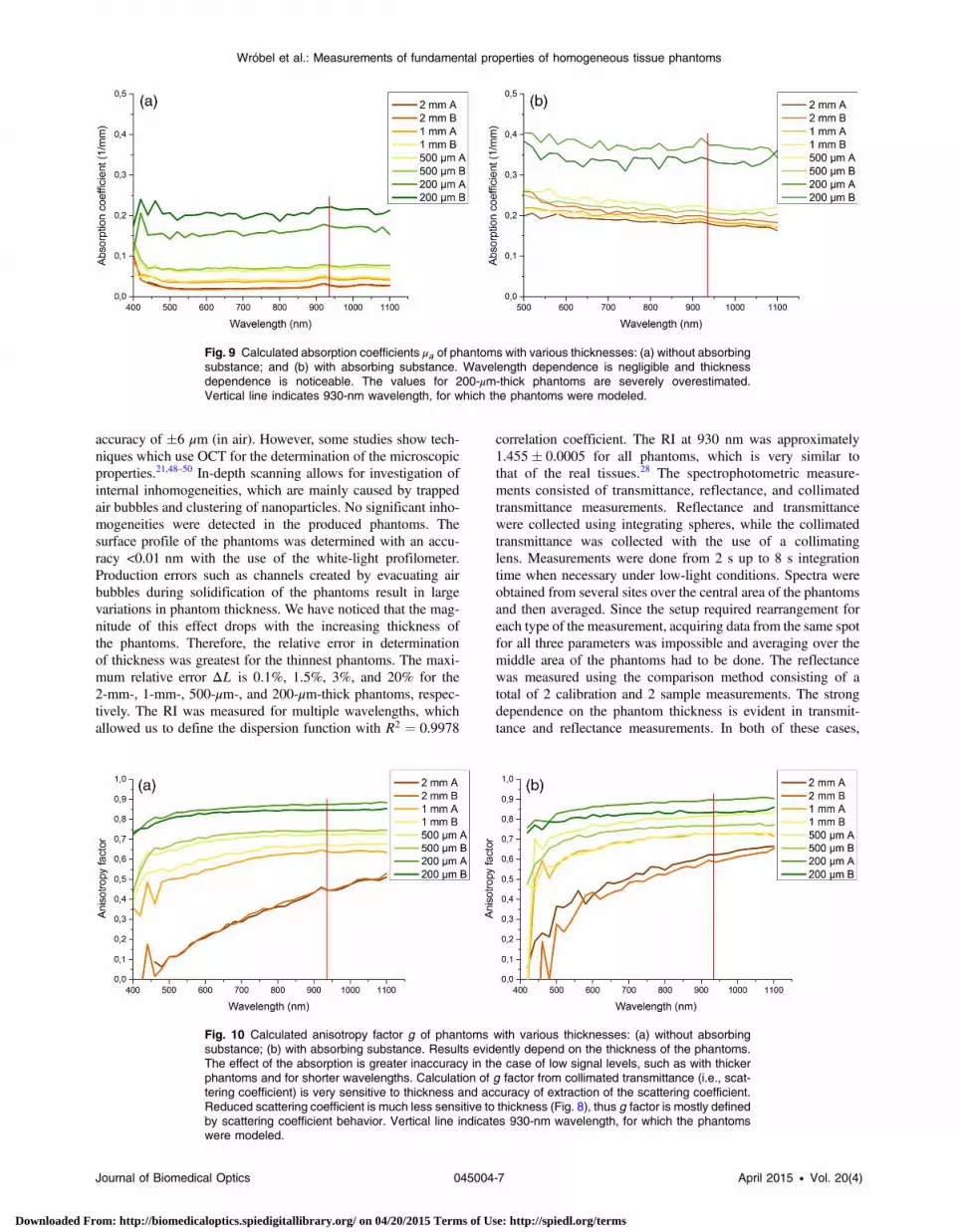
Calculated results for the absorption coefficient (Fig. 9) showthe increase of absorption at 930 nm from 0.05� 0.03 to 0.22�0.03 mm−1 for all phantoms except the 200-μm-thick. Noevident dependence on the wavelength in the full wavelengthrange was indicated. A slight dependence on the thickness of
Fig. 6 Optical coherence tomography (OCT) results: (a) measurement of phantom thickness fromOCT image, L � n denotes the optical path length as a geometrical path length L between the top ofthe phantom and the glass surface multiplied by the refractive index n; (b) OCT image of a 1-mm-thickphantom without absorbing centers; and (c) a 1-mm-thick phantoms with absorbing centers. Depth oflight penetration is notably greater in the first case.
Journal of Biomedical Optics 045004-5 April 2015 • Vol. 20(4)
Wróbel et al.: Measurements of fundamental properties of homogeneous tissue phantoms
Downloaded From: http://biomedicaloptics.spiedigitallibrary.org/ on 04/20/2015 Terms of Use: http://spiedl.org/terms
the phantoms is noticeable. The 200-μm-thick phantoms,
regardless of the addition of absorption, have significantly over-
estimated absorption coefficients.
Calculated scattering anisotropy factors (Fig. 10) vary heavily
with the phantom thickness. According to the theory,27,28
the anisotropy factor depends only on the parameters of the
scattering particles, such as RI, size distribution, and concentra-
tion, and is independent of the thickness of the material. The
scattering coefficient (Fig. 11) was calculated as well, according
to Eq. (1).
5 Discussion
We have presented a number of optical techniques used to char-
acterize properties of developed tissue phantoms designed forsimulating optical properties of human skin at around 930 nm.
The OCT imaging is primarily used as a noninvasive diagnostic
technique and is often the recipient technique of the phantomsfor calibration or research purposes.45–47 Moreover, it can be
used to estimate the phantom geometrical thickness and RI with
a precision dependent on its axial resolution. The thicknesses ofthe produced phantoms were measured with the OCT with an
Fig. 7 Surface roughness results for 2-mm-thick (a, c, e) and 500-μm-thick (b, d, f) phantoms. Phantomsurface profile maps are presented (a, b) (notice uneven color scales), as well as the X and Y axesprofiles (c, d) of the marked cross-sections, and the surface three-dimensional visualizations (e, f).
Fig. 8 Calculated reduced scattering coefficients μ 0s of phantoms with various thicknesses: (a) without
absorbing substance; and (b) with absorbing substance. Vertical line indicates 930-nm wavelength, forwhich the phantoms were modeled.
Journal of Biomedical Optics 045004-6 April 2015 • Vol. 20(4)
Wróbel et al.: Measurements of fundamental properties of homogeneous tissue phantoms
Downloaded From: http://biomedicaloptics.spiedigitallibrary.org/ on 04/20/2015 Terms of Use: http://spiedl.org/terms
accuracy of �6 μm (in air). However, some studies show tech-
niques which use OCT for the determination of the microscopic
properties.21,48–50 In-depth scanning allows for investigation of
internal inhomogeneities, which are mainly caused by trapped
air bubbles and clustering of nanoparticles. No significant inho-
mogeneities were detected in the produced phantoms. The
surface profile of the phantoms was determined with an accu-
racy <0.01 nm with the use of the white-light profilometer.
Production errors such as channels created by evacuating air
bubbles during solidification of the phantoms result in large
variations in phantom thickness. We have noticed that the mag-
nitude of this effect drops with the increasing thickness of
the phantoms. Therefore, the relative error in determination
of thickness was greatest for the thinnest phantoms. The maxi-
mum relative error ΔL is 0.1%, 1.5%, 3%, and 20% for the
2-mm-, 1-mm-, 500-μm-, and 200-μm-thick phantoms, respec-
tively. The RI was measured for multiple wavelengths, which
allowed us to define the dispersion function with R2 ¼ 0.9978
correlation coefficient. The RI at 930 nm was approximately
1.455� 0.0005 for all phantoms, which is very similar to
that of the real tissues.28 The spectrophotometric measure-
ments consisted of transmittance, reflectance, and collimated
transmittance measurements. Reflectance and transmittance
were collected using integrating spheres, while the collimated
transmittance was collected with the use of a collimating
lens. Measurements were done from 2 s up to 8 s integration
time when necessary under low-light conditions. Spectra were
obtained from several sites over the central area of the phantoms
and then averaged. Since the setup required rearrangement for
each type of the measurement, acquiring data from the same spot
for all three parameters was impossible and averaging over the
middle area of the phantoms had to be done. The reflectance
was measured using the comparison method consisting of a
total of 2 calibration and 2 sample measurements. The strong
dependence on the phantom thickness is evident in transmit-
tance and reflectance measurements. In both of these cases,
Fig. 9 Calculated absorption coefficients μa of phantoms with various thicknesses: (a) without absorbingsubstance; and (b) with absorbing substance. Wavelength dependence is negligible and thicknessdependence is noticeable. The values for 200-μm-thick phantoms are severely overestimated.Vertical line indicates 930-nm wavelength, for which the phantoms were modeled.
Fig. 10 Calculated anisotropy factor g of phantoms with various thicknesses: (a) without absorbingsubstance; (b) with absorbing substance. Results evidently depend on the thickness of the phantoms.The effect of the absorption is greater inaccuracy in the case of low signal levels, such as with thickerphantoms and for shorter wavelengths. Calculation of g factor from collimated transmittance (i.e., scat-tering coefficient) is very sensitive to thickness and accuracy of extraction of the scattering coefficient.Reduced scattering coefficient is much less sensitive to thickness (Fig. 8), thus g factor is mostly definedby scattering coefficient behavior. Vertical line indicates 930-nm wavelength, for which the phantomswere modeled.
Journal of Biomedical Optics 045004-7 April 2015 • Vol. 20(4)
Wróbel et al.: Measurements of fundamental properties of homogeneous tissue phantoms
Downloaded From: http://biomedicaloptics.spiedigitallibrary.org/ on 04/20/2015 Terms of Use: http://spiedl.org/terms

the introduction of absorption leads to a decrease of the mea-
sured values, which means that the observations are in agree-
ment with the theoretical assumptions. The amount of light
in collimated transmittance measurements is extremely low and,
therefore, the most susceptible to noise. The results vary greatly
with the phantoms’ thicknesses, even in spot-to-spot measure-
ments over the same phantom. The IAD method was used
to calculate the μ 0s, μa, and g factor. The averaged (over all
samples) reduced scattering coefficient for 930 nm equals
1.74� 0.35 and 1.57� 0.14 mm−1 for nonabsorbing and
absorbing phantoms, respectively. This values lie in close prox-
imity with the values found in the literature for the reduced scat-
tering coefficient of human skin.11–14 This proves the correctness
of theoretical assumptions and the proper fabrication of the
phantoms for the specified goal of mimicking the optical proper-
ties of human skin at 930 nm. The absorption coefficient
increased from 0.05� 0.03 to 0.22� 0.03 mm−1 for all phan-
toms except the 200-μm-thick. These values are in agreement
with the average absorption coefficients found in the literature
data.11–14 The absorption coefficient for 200-μm thick phantoms
was overestimated by 0.2 mm−1. This must be mainly due to the
small size of the phantom, which causes light to escape from the
edges, thus breaking the IAD assumption which was found to
cause overestimations of the absorption coefficient.30,31 The
anisotropy factor results depend greatly on phantom thickness.
Since the anisotropy theoretically depends only on the particle
parameters and their amount and size distribution in a
medium,27,28 it should be constant regardless of the sample
thickness. This leads to the conclusion that the calculated g fac-
tors are based on erroneous measurements. Possible sources of
this error are: (1) surface roughness (thickness difference) of the
phantom surface between the measured spots; (2) uncertainty in
measurements of thickness; (3) low signal intensity on the detec-
tor when measuring TcðλÞ so that the noise introduces a large
amount of error; and (4) detection of partially scattered light in
unscattered transmission measurement, which probably had the
most influence on incorrect g estimation. A quite reasonable
experimental value for the g factor of 0.8 was obtained for
thin samples due to less influence of multiple scattered light on
collimated transmittance measurements in that case and a weak
sensitivity of the reduced scattering coefficient to sample thick-ness. The consequence of the latter has been reported as causingthe estimation of optical properties dependent on the thicknessof the measured material.30,31 This was also evident in our study,however, the μ 0
s and μa dependences on thickness were mostlyacceptable as an expected inaccuracy of estimation caused bythe limited accuracy of the measurements.
Acknowledgments
This study was partially supported by the Polish NationalScience Center under the grant 2011/03/D/ST7/03540, FNPproject under the grant no. 48/UD/SKILLS/2014, as well as DSPrograms of the Faculty of Electronics, Telecommunicationsand Informatics, Gdańsk University of Technology. We alsoacknowledge the support from the FiDiPro project 40111/11 ofTEKES, BM1205 COST Action, Government of the RussianFederation (Grant No. 14.Z50.31.0004 to support scientificresearch projects implemented under the supervision of leadingscientists) and Russian Presidential grant NSh-703.2014.2.
References
1. V. O. Korhonen et al., “Light propagation in NIR spectroscopy of
the human brain,” IEEE J. Sel. Top. Quantum Electron. 20, 1–10
(2014).
2. T. Myllylä et al., “Optical sensing of a pulsating liquid in a brain-mim-
icking phantom,” Proc. SPIE 8799, 87990X (2013).
3. E. Alarousu et al., “Noninvasive glucose sensing in scattering media using
OCT, PAS, and TOF techniques,” Proc. SPIE 5474, 33–41 (2004).
4. M. Jedrzejewska-Szczerska et al., “Fiber-optic temperature sensor using
low-coherence interferometry,” Eur. Phys. J. Spec. Top. 154(1), 107–111
(2008).
5. A. E. Cerussi et al., “Tissue phantoms in multicenter clinical trials for
diffuse optical technologies,” Biomed. Opt. Express 3, 966–971 (2012).
6. H. S. S. Sorvoja et al., “Non-invasive, MRI-compatible fibreoptic device
for functional near-IR reflectometry of human brain,” Quantum Electron.
40, 1067 (2010).
7. J. Hwang, J. C. Ramella-Roman, and R. Nordstrom, “Introduction: fea-
ture issue on phantoms for the performance evaluation and validation of
optical medical imaging devices,” Biomed. Opt. Express 3, 1399–1403
(2012).
8. M. L. Clarke et al., “Designing microarray phantoms for hyperspectral
imaging validation,” Biomed. Opt. Express 3, 1291–1299 (2012).
Fig. 11 Calculated scattering coefficient μs of phantoms with various thicknesses: (a) without absorbingsubstance; and (b) with absorbing substance. Calculated scattering is dependent on phantom thickness.The introduction of absorbing agent does not interfere strongly with the scattering properties. Therefore,matching each parameter independently is possible with the used scattering and absorbing substances.Vertical line indicates 930-nm wavelength, for which the phantoms were modeled.
Journal of Biomedical Optics 045004-8 April 2015 • Vol. 20(4)
Wróbel et al.: Measurements of fundamental properties of homogeneous tissue phantoms
Downloaded From: http://biomedicaloptics.spiedigitallibrary.org/ on 04/20/2015 Terms of Use: http://spiedl.org/terms
9. D. V. Samarov et al., “Algorithm validation using multicolor phantoms,”
Biomed. Opt. Express 3, 1300–1311 (2012).
10. A. Mazikowski, R. Hypszer, and M. Jedrzejewska-Szczerska,
“Modeling of non-contact temperature measurement system using
multiwavelength pyrometry,” Proc. SPIE 4516, 120–124 (2001).
11. W.-F. Cheong, S. A. Prahl, and A. J. Welch, “A review of the optical
properties of biological tissues,” IEEE J. Quantum Electron. 26, 2166–
2185 (1990).
12. A. N. Bashkatov, E. A. Genina, and V. V. Tuchin, “Optical properties of
skin, subcutaneous, and muscle tissues: a review,” J. Innovative Opt.
Health Sci. 04, 9–38 (2011).
13. T. Lister, P. A. Wright, and P. H. Chappell, “Optical properties of human
skin,” J. Biomed. Opt. 17, 090901 (2012).
14. S. L. Jacques, “Optical properties of biological tissues: a review,” Phys.
Med. Biol. 58, R37–R61 (2013).
15. M. S. Wróbel et al., “Multi-layered tissue head phantoms for non-
invasive optical diagnostics,” J. Innovative Opt. Health Sci. 8, 1541005
(2015).
16. B. W. Pogue and M. S. Patterson, “Review of tissue simulating phan-
toms for optical spectroscopy, imaging and dosimetry,” J. Biomed. Opt.
11, 041102 (2006).
17. R. J. Nordstrom, “Phantoms as standards in optical measurements,”
Proc. SPIE 7906, 79060H (2011).
18. G. Lamouche et al., “Review of tissue simulating phantoms with con-
trollable optical, mechanical and structural properties for use in optical
coherence tomography,” Biomed. Opt. Express 3, 1381–1398 (2012).
19. R. B. Saager et al., “Multilayer silicone phantoms for the evaluation of
quantitative optical techniques in skin imaging,” Proc. SPIE 7567,
756706 (2010).
20. M. Jedrzejewska-Szczerska et al., “Investigation of photothermolysis
therapy of human skin diseases using optical phantoms,” Proc. SPIE
9447, 944715 (2015).
21. A. Agrawal et al., “Characterizing the point spread function of retinal
OCT devices with a model eye-based phantom,” Biomed. Opt. Express
3, 1116–1126 (2012).
22. R. C. Chang et al., “Fabrication and characterization of a multilayered
optical tissue model with embedded scattering microspheres in poly-
meric materials,” Biomed. Opt. Express 3, 1326–1339 (2012).
23. J. Fu et al., “A simple method of obtaining the reduced scattering coef-
ficients of tissue-simulating phantoms,” J. Innovative Opt. Health Sci.
03, 53 (2010).
24. S. L. Jacques, B. Wang, and R. Samatham, “Reflectance confocal
microscopy of optical phantoms,” Biomed. Opt. Express 3, 1162–1172
(2012).
25. H. Kang et al., “Multimodal optical studies of single and clustered
colloidal quantum dots for the long-term optical property evaluation of
quantum dot-based molecular imaging phantoms,” Biomed. Opt. Express
3, 1312–1325 (2012).
26. S. C. Kanick et al., “Scattering phase function spectrum makes reflec-
tance spectrum measured from Intralipid phantoms and tissue sensitive
to the device detection geometry,” Biomed. Opt. Express 3, 1086–1100
(2012).
27. V. V. Tuchin, “Light scattering study of tissues,” Phys.-Usp. 40, 495
(1997).
28. V. V. Tuchin, Tissue Optics: Light Scattering Methods and Instruments
for Medical Diagnosis, SPIE Press, Bellingham, Washington (2007).
29. B. C. Wilson, M. S. Patterson, and S. T. Flock, “Indirect versus direct
techniques for the measurement of the optical properties of tissues,”
Photochem. Photobiol. 46, 601–608 (1987).
30. J. W. Pickering et al., “Double-integrating-sphere system for measuring
the optical properties of tissue,” Appl. Opt. 32, 399–410 (1993).
31. S. A. Prahl, M. J. van Gemert, and A. J. Welch, “Determining the optical
properties of turbid media by using the adding-doubling method,”
Appl. Opt. 32, 559–568 (1993).
32. J. R. Mourant et al., “Predictions and measurements of scattering and
absorption over broad wavelength ranges in tissue phantoms,” Appl.
Opt. 36, 949–957 (1997).
33. G. C. Beck et al., “Design and characterization of a tissue phantom
system for optical diagnostics,” Lasers Med. Sci. 13, 160–171 (1998).
34. T. Moffitt, Y.-C. Chen, and S. A. Prahl, “Preparation and characteriza-
tion of polyurethane optical phantoms,” J. Biomed. Opt. 11, 041103
(2006).
35. S. S. Kumar et al., “Synthesis, characterization and optical properties of
zinc oxide nanoparticles,” Int. Nano Lett. 3, 1–6 (2013).
36. Q. Wang, K. Shastri, and T. J. Pfefer, “Experimental and theoretical
evaluation of a fiber-optic approach for optical property measurement
in layered epithelial tissue,” Appl. Opt. 49, 5309–5320 (2010).
37. R. X. Xu et al., “Dual-mode imaging of cutaneous tissue oxygenation
and vascular function,” J. Visualized Exp. 46, 2095 (2010).
38. L. Luu et al., “Microfluidics based phantoms of superficial vascular
network,” Biomed. Opt. Express 3, 1350–1364 (2012).
39. T. T. Nguyen et al., “Three-dimensional phantoms for curvature correc-
tion in spatial frequency domain imaging,” Biomed. Opt. Express
3, 1200–1214 (2012).
40. H. C. van de Hulst, Light Scattering by Small Particles, Dover
Publications, New York (1981).
41. M. Jedrzejewska-Szczerska, B. B. Kosmowski, and R. Hypszer,
“Shaping of coherence function of sources used in low-coherent
measurement techniques,” J. Phys. IV 137, 103–106 (2006).
42. M. Jedrzejewska-Szczerska, “Shaping coherence function of sources
used in low-coherent measurement techniques,” Eur. Phys. J.-Spec.
Top. 144, 203–208 (2007).
43. J. Pluciński et al., “Optical low-coherence interferometry for selected
technical applications,” Bull. Pol. Acad. Sci. Tech. Sci. 56(2), 155–172
(2008).
44. M. Jedrzejewska-Szczerska et al., “Theoretical and experimental
investigation of low-noise optoelectronic system configurations for
low-coherent optical signal detection,” J. Phys. IV France 137, 107–110
(2006).
45. A. V. Bykov et al., “Skin phantoms with realistic vessel structure for
OCT measurements,” Proc. SPIE 7376, 73760F (2010).
46. A. V. Bykov et al., “Multilayer tissue phantoms with embedded capillary
system for OCT and DOCT imaging,” Proc. SPIE 8091, 80911R (2011).
47. J. Baxi et al., “Retina-simulating phantom for optical coherence tomog-
raphy,” J. Biomed. Opt. 19, 021106 (2014).
48. D. Faber et al., “Quantitative measurement of attenuation coefficients of
weakly scattering media using optical coherence tomography,” Opt.
Express 12, 4353–4365 (2004).
49. Y. Yang et al., “Optical scattering coefficient estimated by optical coher-
ence tomography correlates with collagen content in ovarian tissue,”
J. Biomed. Opt. 16, 090504 (2011).
50. X. Xu, J. Lin, and F. Fu, “Optical coherence tomography to investigate
optical properties of blood during coagulation,” J. Biomed. Opt. 16(9),
096002 (2011).
Maciej S. Wróbel received his BSc and MSc degrees in electronicsand telecommunication, with a specialty of optoelectronics, fromGdańsk University of Technology in 2012 and 2013, respectively.He is currently a PhD student at the same university. His mainresearch area is biophotonics and he focuses on spectroscopic meth-ods of biotissue analysis, tissue-mimicking phantoms for noninvasiveoptical sensing, signal processing, and fiber-optic sensors.
Alexey P. Popov graduated from the Physics Department of MoscowState University (Russia) in 2003 and received his PhD in 2006 fromthe same university and his DSc(Tech) degree from the University ofOulu (Finland) in 2008. He is currently a docent in the University ofOulu. His scientific interests are in the area of nanobiophotonics,nanoparticle-light-tissue-cell interaction, including biotissue-mimick-ing phantoms, deep-tissue imaging using up-conversion nanopar-ticles, enhancement of skin UV protection by sunscreens, and celloptoporation by plasmonic nanostructures.
Alexander V. Bykov is a postdoctoral researcher in the University ofOulu. He received his MSc diploma in physics at the M.V. LomonosovMoscow State University in 2005 and his PhD in 2008 from the sameuniversity. In 2010 he received a DSc(Tech) degree from theUniversity of Oulu. His scientific interests are in the area of biopho-tonics, noninvasive optical diagnostics, theory of light propagationin scattering media including biotissues, and numerical simulationof light transport.
Matti Kinnunen received his MSc (Tech) and DSc (Tech) degrees inelectrical engineering from the University of Oulu, Oulu, Finland, in2002 and 2006, respectively. He is currently working as a seniorresearch fellow at the University of Oulu. His research interests
Journal of Biomedical Optics 045004-9 April 2015 • Vol. 20(4)
Wróbel et al.: Measurements of fundamental properties of homogeneous tissue phantoms
Downloaded From: http://biomedicaloptics.spiedigitallibrary.org/ on 04/20/2015 Terms of Use: http://spiedl.org/terms

include light-matter interactions in tissues and at the single cell level,sensors and measurement techniques, as well as optical noninvasivemeasurement techniques for biomedical applications.
Malgorzata Jedrzejewska-Szczerska received her PhD degree withhonors in electronics from the Gdańsk University of Technology in2008. Currently she is an assistant professor in the Department ofMetrology and Optoelectronics. Her main research area is biopho-tonics, and she focuses on use of low-coherence interferometry,fiber-optic technology, and application of optical measurements inbiomedicine.
Valery V. Tuchin is a professor and chairman of Optics andBiophotonics at Saratov State University, Russia. He is also thehead of laboratory, Institute of Precision Mechanics and Control,RAS. His research interests include biophotonics, tissue optics,laser medicine, tissue optical clearing, and nanobiophotonics. He isa member of SPIE, OSA, and IEEE, and a fellow of SPIE and hasbeen awarded honored science worker of the Russia, SPIE educatoraward, and FiDiPro (Finland).
Journal of Biomedical Optics 045004-10 April 2015 • Vol. 20(4)
Wróbel et al.: Measurements of fundamental properties of homogeneous tissue phantoms
Downloaded From: http://biomedicaloptics.spiedigitallibrary.org/ on 04/20/2015 Terms of Use: http://spiedl.org/terms