a fundamental constants
TRANSCRIPT
A
Fundamental Constants
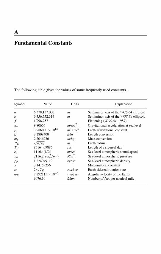
The following table gives the values of some frequently used constants.
Symbol Value Units Explanation
a 6,378,137.000 m Semimajor axis of the WGS-84 ellipsoidb 6,356,752.314 m Semiminor axis of the WGS-84 ellipsoidf 1/298.257 - Flattening (WGS-84, 1987)go 9.80665 m/sec2 Gravitational acceleration at sea levelµ 3.986030 × 10¹⁴ m3/sec2 Earth gravitational constantlc 3.2808400 ft/m Length conversionmc 2.2046226 lb/kg Mass conversionRE
õ/go m Earth radius
TE 86164.09886 sec Length of a sidereal dayco 1116.4(1/lc) m/sec Sea-level atmospheric sound speedpo 2116.2(gol2c /mc) N/m2 Sea-level atmospheric pressureρo 1.224949119 kg/m3 Sea-level atmospheric densityπ 3.14159256 Mathematical constantω 2π/TE rad/sec Earth sidereal rotation rateωE 7.292115 × 10⁻⁵ rad/sec Angular velocity of the Earth
6076.10 ft/nm Number of feet per nautical mile
B
Glossary of Terms
The following celestial mechanics terms are commonly used in deriving the free flightof ballistic missiles.
Anomaly – An angle; for example, eccentric anomaly, mean anomaly, true anomaly.• Eccentric Anomaly – An angle at the center of an ellipse between the line of
apsides and the radius of the auxiliary circle through a point having the sameapsidal distance as a given point on the ellipse.
• Mean Anomaly – The angle through which an object would move atthe uniform average angular speed n measured from the principal focus.Commonly, the angle n(t − to) is called the mean anomaly, where n is themean motion.
• True Anomaly – The angle at the focus between the line of apsides and theradius vector measured in the direction of orbital motion; the angle measuredin the direction in which the orbit is described, starting from perihelion.
Aphelion – The point on an elliptical orbit about the sun that is farthest from thesun.
Apoapsis – The point farthest from the principal focus of an orbit in a central forcefield.
Apogee – The highest point on an Earth-centered elliptical orbit. The point ofintersection of the trajectory and its semimajor axis that lies farthest from theprincipal focus.
Apsides (or Line of Apsides) – In an elliptical orbit, the major axis.Apsis – The point on a conic where the radius vector is a maximum or a minimum.Celestial Equator – The great circle on the celestial sphere that is formed by the
intersection of the celestial sphere with the plane of the Earth’s equator. Forsolar system applications, it is formed by intersection with the ecliptic.
Celestial Horizon – The celestial horizon of an observer is the great circle of thecelestial sphere that is everywhere 90◦ from the observer’s zenith.
Celestial Sphere – A sphere of infinite radius with its center at the center of theEarth upon which the stars and other astronomical bodies appear to be projected.This sphere is fixed in space and appears to rotate counter to the diurnal rotation
592 B Glossary of Terms
of the Earth. For solar system navigation purposes, the celestial sphere may beconsidered to be centered at the Sun.
Colatitude – Defined as 90◦ – ϕ, where ϕ is the latitude.Coordinates on the Celestial Sphere – Polar coordinates are used in specifying
the location of a star or other heavenly body on the celestial sphere. These arethe declination (δ) and the right ascension (R.A.).
Declination – The declination of a star is the angular distance north or south, ofthe celestial equator measured on the celestial sphere.
Earth rate – The angular velocity at which the Earth rotates about its own polaraxis. The Earth rate is equal to 15.041◦/hr or 7.29215 × 10⁻⁵ rad/sec.
Ecliptic – The great circle on the celestial sphere that is formed by its intersectionwith the plane of the Earth’s orbit.
Ellipticity – Deviation of an ellipse or a spheroid from the form of a circle or asphere. The Earth is assumed to have an ellipticity of about 1/297.
Epoch – Arbitrary instant of time for which elements of an orbit are valid.First Point of Aries (ϒ) – Vernal equinox.Geocentric – Pertaining to the center of the Earth as a reference.Geocentric Coordinates – Coordinates on the celestial sphere as they would be
observed from the center of the Earth.Geodetic Latitude – Geodetic latitude is defined as the angle between the equa-
torial plane and the normal to the surface of the ellipsoid. It is the latitudecommonly used on maps and charts.
Geodesic Line – The shortest line on the curved surface of the Earth between twopoints. (see also Great Circle).
Geographic – Pertaining to the location of a point, line, or area on the Earth’ssurface.
Gravity – A vertical force acting on all bodies and mass in or around the Earth. Themagnitude of the force of gravity varies with location on the Earth and elevationor altitude above mean sea level. This force will cause a free body to accelerateapproximately 32.16 ft/sec2 (or 9.80665 m/sec2). (Commonly abbreviated bythe letter g.)
Great Circle – A circle on the surface of the Earth, the plane of which passesthrough the center of the Earth, dividing it into two equal parts. A course plottedon a great circle is the shortest distance between two points on the surface ofthe Earth and is called a geodesic line.
Hour Circle – A great circle of the celestial sphere that passes through the polesand a celestial body.
Hyperbolic Excess Velocity – In the two-body problem, the relative velocity ofthe bodies after escape from the mutual potential field.
Nadir – The nadir is the point of the celestial sphere 180◦ from the zenith.North Celestial Pole – This is the point of intersection of the Earth’s axis of
rotation with the celestial sphere. In solar system navigation applications, thecelestial poles form a line normal to the ecliptic plane while preserving thesense of the north–south orientation.
B Glossary of Terms 593
Orbital Elements – The orbit of a body that is attracted by an inverse-square centralforce can be specified unambiguously by six elements, which are constants ofintegration from the equations of motion. These parameters (or orbital elements)define an elliptic orbit in space and are as follows: (1) semimajor axis (a),which specifies the size; (2) eccentricity (e), specifies shape and size; (3) time ofperigee passage (T ), specifies path position at a given time; (4) orbit inclinationangle (i), specifies the orientation of the orbital plane to the equatorial plane(0 ≤ i ≤ 180◦); (5) longitude of the ascending node (�), specifies the angulardistance between the first point of Aries (ϒ) and the ascending side of the lineof nodes; (6) argument of perigee (ω), an angle that specifies the orientationof the ellipse within its own plane. It should be noted that the definition ofthese elements may differ from those given in books on celestial mechanics.For example, in these books, the mean longitude, epoch, mean motion, andlongitude of perihelion are also included.
Parameters (Orbit) – Orbital elements.Parameters (Flight) – Descriptive quantities that define the flight conditions rela-
tive to a selected reference frame.Periapsis – In an elliptical orbit, the apses closest to the nonvacant focus. In an
open orbit, the point of closest approach to the orbit center.Perigee – The point in the orbit of a spacecraft that is closest to the Earth when
the orbit is about the Earth.Perihelion – The point of an orbit about the Sun that is closest to the Sun.Reference, Inertial Space – A system of coordinates that are unaccelerated with
respect to the fixed stars.Retrograde – Orbital motion in a direction opposite to that of the planets in the
solar system, that is, clockwise as seen from the north of the ecliptic.Right Ascension (R.A.) – The right ascension of a star is the angle, measured
eastward along the celestial equator, from the vernal equinox to the great circlepassing through the north celestial pole and the star under observation. Rightascension is frequently expressed in hours, minutes, and seconds of siderealtime (i.e., 1 hour is equal to 15◦) because clocks are used in the terrestrialmeasurement of right ascension.
Sidereal Hour Angle – The sidereal hour angle of a celestial body is the angle atthe pole between the hour circle of the vernal equinox and the hour circle ofthe body, measured westward from the hour circle of the vernal equinox from0◦ to 360◦.
Sidereal Day – A sidereal day is the interval of time between two successivetransits of the vernal equinox over the same meridian.
24h sidereal time = 23h 56m 04.1s civil time;
conversely,24h civil time = 24h03m56.6s sidereal time.
Time – In astronomical usage, time is usually expressed as universal time (UT).This is identical with Greenwich Civil Time and is counted from 0 to 24 hours

594 B Glossary of Terms
beginning with midnight. A decimal subdivision is often used in place of hours,minutes, and seconds. Thus, the following are all identical:Nov 30.75 UT,Nov 30; 18h 00m UT,Nov 30; 1800Z,Nov 30; 1:00 PM EST.
Topocentric Coordinates – Coordinates on the celestial sphere as observed fromthe surface of the Earth.
Topocentric Parallax – The difference between geocentric and topocentric posi-tions of a body in the sky.
Vernal Equinox – The point where the Sun appears to cross the celestial equatorfrom south to north. The time of this crossing, when day and night are every-where of equal length, occurs at about 21 March. Also known as first point ofAries and designated by the symbol ϒ .
Zenith – The point on the celestial sphere vertically overhead (its direction canbe defined by means of a plumb-line).
C
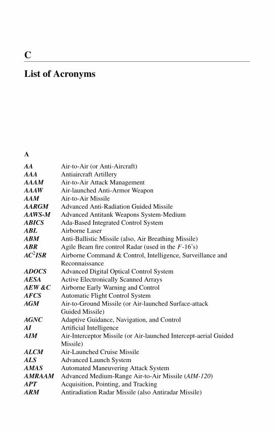
List of Acronyms
A
AA Air-to-Air (or Anti-Aircraft)AAA Antiaircraft ArtilleryAAAM Air-to-Air Attack ManagementAAAW Air-launched Anti-Armor WeaponAAM Air-to-Air MissileAARGM Advanced Anti-Radiation Guided MissileAAWS-M Advanced Antitank Weapons System-MediumABICS Ada-Based Integrated Control SystemABL Airborne LaserABM Anti-Ballistic Missile (also, Air Breathing Missile)ABR Agile Beam fire control Radar (used in the F -16’s)AC2ISR Airborne Command & Control, Intelligence, Surveillance and
ReconnaissanceADOCS Advanced Digital Optical Control SystemAESA Active Electronically Scanned ArraysAEW &C Airborne Early Warning and ControlAFCS Automatic Flight Control SystemAGM Air-to-Ground Missile (or Air-launched Surface-attack
Guided Missile)AGNC Adaptive Guidance, Navigation, and ControlAI Artificial IntelligenceAIM Air-Interceptor Missile (or Air-launched Intercept-aerial Guided
Missile)ALCM Air-Launched Cruise MissileALS Advanced Launch SystemAMAS Automated Maneuvering Attack SystemAMRAAM Advanced Medium-Range Air-to-Air Missile (AIM-120)APT Acquisition, Pointing, and TrackingARM Antiradiation Radar Missile (also Antiradar Missile)
596 C List of Acronyms
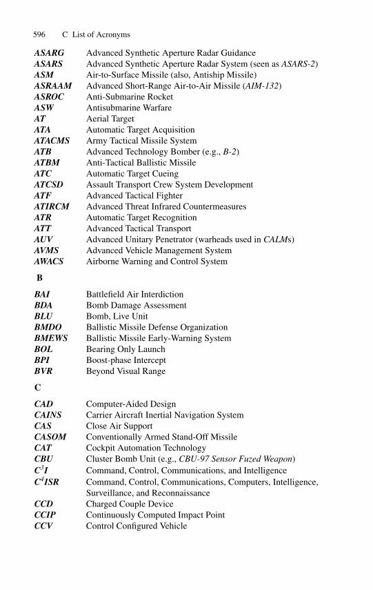
ASARG Advanced Synthetic Aperture Radar GuidanceASARS Advanced Synthetic Aperture Radar System (seen as ASARS-2)ASM Air-to-Surface Missile (also, Antiship Missile)ASRAAM Advanced Short-Range Air-to-Air Missile (AIM-132)ASROC Anti-Submarine RocketASW Antisubmarine WarfareAT Aerial TargetATA Automatic Target AcquisitionATACMS Army Tactical Missile SystemATB Advanced Technology Bomber (e.g., B-2)ATBM Anti-Tactical Ballistic MissileATC Automatic Target CueingATCSD Assault Transport Crew System DevelopmentATF Advanced Tactical FighterATIRCM Advanced Threat Infrared CountermeasuresATR Automatic Target RecognitionATT Advanced Tactical TransportAUV Advanced Unitary Penetrator (warheads used in CALMs)AVMS Advanced Vehicle Management SystemAWACS Airborne Warning and Control System
B
BAI Battlefield Air InterdictionBDA Bomb Damage AssessmentBLU Bomb, Live UnitBMDO Ballistic Missile Defense OrganizationBMEWS Ballistic Missile Early-Warning SystemBOL Bearing Only LaunchBPI Boost-phase InterceptBVR Beyond Visual Range
C
CAD Computer-Aided DesignCAINS Carrier Aircraft Inertial Navigation SystemCAS Close Air SupportCASOM Conventionally Armed Stand-Off MissileCAT Cockpit Automation TechnologyCBU Cluster Bomb Unit (e.g., CBU-97 Sensor Fuzed Weapon)C3I Command, Control, Communications, and IntelligenceC4ISR Command, Control, Communications, Computers, Intelligence,
Surveillance, and ReconnaissanceCCD Charged Couple DeviceCCIP Continuously Computed Impact PointCCV Control Configured Vehicle
C List of Acronyms 597
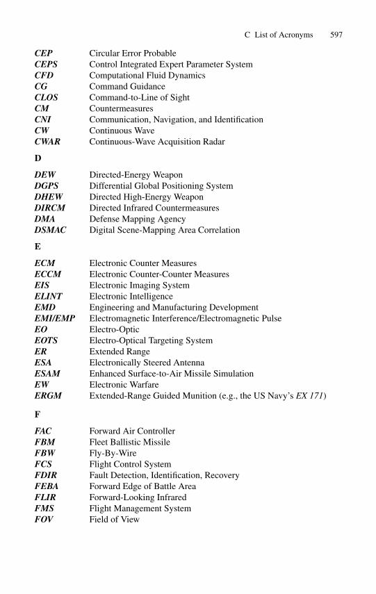
CEP Circular Error ProbableCEPS Control Integrated Expert Parameter SystemCFD Computational Fluid DynamicsCG Command GuidanceCLOS Command-to-Line of SightCM CountermeasuresCNI Communication, Navigation, and IdentificationCW Continuous WaveCWAR Continuous-Wave Acquisition Radar
D
DEW Directed-Energy WeaponDGPS Differential Global Positioning SystemDHEW Directed High-Energy WeaponDIRCM Directed Infrared CountermeasuresDMA Defense Mapping AgencyDSMAC Digital Scene-Mapping Area Correlation
E
ECM Electronic Counter MeasuresECCM Electronic Counter-Counter MeasuresEIS Electronic Imaging SystemELINT Electronic IntelligenceEMD Engineering and Manufacturing DevelopmentEMI/EMP Electromagnetic Interference/Electromagnetic PulseEO Electro-OpticEOTS Electro-Optical Targeting SystemER Extended RangeESA Electronically Steered AntennaESAM Enhanced Surface-to-Air Missile SimulationEW Electronic WarfareERGM Extended-Range Guided Munition (e.g., the US Navy’s EX 171)
F
FAC Forward Air ControllerFBM Fleet Ballistic MissileFBW Fly-By-WireFCS Flight Control SystemFDIR Fault Detection, Identification, RecoveryFEBA Forward Edge of Battle AreaFLIR Forward-Looking InfraredFMS Flight Management SystemFOV Field of View
598 C List of Acronyms
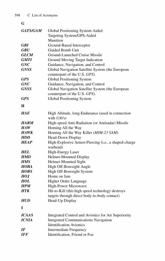
G
GATS/GAM Global Positioning System-AidedTargeting System/GPS-AidedMunition
GBI Ground-Based InterceptorGBU Guided Bomb UnitGLCM Ground-Launched Cruise MissileGMTI Ground Moving Target IndicationGNC Guidance, Navigation, and ControlGNSS Global Navigation Satellite System (the European
counterpart of the U.S. GPS).GPS Global Positioning SystemGNC Guidance, Navigation, and ControlGNSS Global Navigation Satellite System (the European
counterpart of the U.S. GPS).GPS Global Positioning System
H
HAE High Altitude, long-Endurance (used in connectionwith UAVs)
HARM High-speed Anti-Radiation (or Antiradar) MissileHAW Homing All the WayHAWK Homing All the Way Killer (MIM-23 SAM)HDD Head-Down DisplayHEAP High-Explosive Armor-Piercing (i.e., a shaped-charge
warhead)HEL High-Energy LaserHMD Helmet-Mounted DisplayHMS Helmet-Mounted SightHOBA High Off-Boresight AngleHOBS High Off-Boresight SystemHOJ Home on JamHOL Higher Order LanguageHPM High-Power MicrowaveHTK Hit-to-Kill (this high speed technology destroys
targets through direct body-to-body contact)HUD Head-Up Display
I
ICAAS Integrated Control and Avionics for Air SuperiorityICNIA Integrated Communications Navigation
Identification AvionicsIF Intermediate FrequencyIFF Identification, Friend or Foe
C List of Acronyms 599
IFFC Integrated Flight/Fire ControlsIFPS Intra-Formation Positioning SystemIFTS Internal Forward-looking infrared and Targeting SystemIFWC Integrated Flight/Weapon ControlsIIR Imaging InfraredINS Inertial Navigation SystemI/O Input/OutputIOC Initial Operating CapabilityIOT&E Initial Operational Test and EvaluationIR InfraredIRCCM Infrared Counter-CountermeasuresIRCM Infrared CountermeasuresIRLS Infrared Line ScanIRSS Infrared Suppressor SystemIRST Infrared Search and TrackIRVAT Infrared Video Automatic TrackingISAR Inverse Synthetic Aperture Radar (used for target
motion detection)ISR Intelligence gathering, Surveillance, and ReconnaissanceITAG Inertial Terrain-Aided Guidance
J
JASSM Joint Air-to-Surface Standoff MissileJAST Joint Advanced Strike TechnologyJDAM Joint Direct Attack MunitionJDAM-ER Joint Direct Attack Munitions-Extended RangeJHMCS Joint Helmet-Mounted Cueing SystemJ/S Jamming to Signal RatioJSOW Joint Standoff WeaponJSTARS Joint Surveillance Target Attack Radar SystemJTIDS Joint Tactical Information Distribution System
K
KEW Kinetic Energy Weapon
L
LADAR Laser Radar, or Laser Amplitude Detection And RangingLAIRCM Large Aircraft Infrared MeasuresLANTIRN Low Altitude Navigation and Targeting Infrared for NightLASM Land Attack Standard Missile (a US Navy missile launched from
the DDG 51 destroyers and cruisers)LASS Low Altitude Surveillance SystemLGB Laser-Guided BombLLLGB Low-Level LGB
600 C List of Acronyms
LOBL Lock-On Before Launch(e.g., Hellfire AGM-114)
LOCAAS Low-Cost Autonomous Attack System(note: System is also seen as Submunition)
LOS Line-of-SightLOV Low Observable VehicleLQG Linear Quadratic GaussianLST Laser Spot Tracker
M
MALD Miniature Air Launched DecoyMAP Mission Area PlanMaRV Maneuvering Reentry VehicleMAWS Missile Approach Warning SystemMEAD Multidisciplinary Expert-Aided DesignMEMS Micro-Electro-Mechanical SensorsMFCRS Multi-Function Control Reference SystemMIM Mobile Interceptor MissileMIMO Multi-Input, Multi-OutputMIRV Multiple Independently targetable Reentry VehicleMk Mark (General Purpose Bomb)MLRS Multiple-Launch Rocket SystemMMS Mission Management SystemMMW Millimeter WaveMR Medium RangeMTI Moving Target Indication (or Indicator)
N
NMD National Missile Defense
O
OAS Offensive Avionics SystemOTH Over The Horizon
P
PA Pilot’s AssociatePBW Power-By-WirePGM Precision-Guided MunitionPTAN Precision Terrain Aided Navigation (used in the TacTom or Tactical
Tomahawk missile).PVI Pilot Vehicle Interface
R
RADAG Radar Area GuidanceRAM Rolling Airframe Missile
C List of Acronyms 601
RCS Radar Cross-SectionRESA Rotating Electronically Scanned ArrayRF Radio FrequencyRFI Radio Frequency InterferenceRHWR Radar Homing and Warning ReceiverRPV Remotely Piloted VehicleRV Reentry VehicleRWR Radar Warning ReceiverRWS Range-While-Scan
S
SACLOS Semi-Active Command to Line-of-SightSAH Semi-Active HomingSAM Surface-to-Air MissileSAR Synthetic Aperture radarSA/SA Situational Awareness/Situation AssessmentSATCOM Satellite CommunicationsSCAD Subsonic Cruise Armed DecoySDB Small-Diameter BombSDI Strategic (or Space) Defense InitiativeSEAD Suppression of Enemy Air DefensesSFW Sensor Fuzed Weapon (i.e., this is an unguided gravity weapon)SIGINT Signal Intelligence (also seen as Sigint)SLAM Standoff Land-Attack MissileSLAM-ER Standoff Land-Attack Missile – Expanded ResponseSLBM Submarine (or Sea)-Launched Ballistic MissileSLCM Sea-Launched Cruise MissileSNR Signal-to-Noise RatioSOF Special Operations ForcesSRAM Short-Range Attack MissileSSBXR Small Smart Bomb Extended Range (a JDAM spin-off)SSGNs Nuclear-powered Guided-missile submarinesSSNs Nuclear-powered attack submarinesSSST Supersonic Sea-Skimming TargetSTART Strategic Arms Reduction TreatySTOL Short Take-Off and LandingSTOVL Shorts Take-Off and Vertical Landing
T
TADS Terrain Awareness and Display SystemTAINS TERCOM-Aided Inertial Navigation SystemTAMD Theater Air and Missile DefenseTAN Terrain-Aided NavigationTAP Technology Area Plan
602 C List of Acronyms
TAWS Terrain Awareness and Warning System, orTheater Airborne Warning System (this is an IR capability)
TBM Theater Ballistic Missile (also called Tactical Ballistic Missile)TERCOM Terrain-Contour MatchingTERPROM Terrain Profile MatchingTFLIR Targeting Forward-Looking InfraredTFR Terrain-Following RadarTF/TA2 Terrain Following/Terrain Avoidance/Threat AvoidanceTGSM Terminally Guided Sub-MunitionTGW Terminally Guided WarheadTHAAD Theater High Altitude Area DefenseTIALD Thermal Imaging Airborne Laser DesignatorTIAS Target Identification and Acquisition SystemTLAM Tomahawk Land Attack MissileTMD Theater Missile Defense (also: Tactical Munitions Dispenser)TOW Tube-launched, Optically-tracked, Wire-guidedTRAM Target-Recognition Attack MultisensorTSS Target Sight System (uses focal plane array FLIR and LST)T-UAV Tactical Unmanned Aerial VehicleTVC Thrust Vector ControlTVM Track-Via-MissileTWS Track-While-Scan (a multiple target tracking radar)
U
UAV Unmanned Aerial (or Air) VehicleUCAV Unmanned Combat Air Vehicle (also seen as “Uninhabited
Combat Aerial Vehicle”)UHF Ultra High-FrequencyURAV Unmanned Reconnaissance Air VehicleURV Unmanned Research VehicleUSW Undersea Warfare
V
VCATS Visually-Coupled Acquisition and Targeting SystemVHSIC Very High Speed Integrated CircuitVLS Vertical Launch SystemVLSI Very Large Scale IntegrationVMS Vehicle Management SystemVR Virtual RealityVSIM Virtual SimulatorVSTOL Vertical/Short Takeoff and LandingVTAS Visual Target Acquisition System

C List of Acronyms 603
W
WCMD Wind Corrected Munitions DispenserWGS World Geodetic SystemWMD Weapons of Mass DestructionWVR Within Visual Range
D
The Standard Atmospheric Model
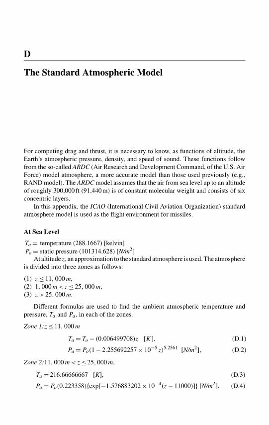
For computing drag and thrust, it is necessary to know, as functions of altitude, theEarth’s atmospheric pressure, density, and speed of sound. These functions followfrom the so-called ARDC (Air Research and Development Command, of the U.S. AirForce) model atmosphere, a more accurate model than those used previously (e.g.,RAND model). The ARDC model assumes that the air from sea level up to an altitudeof roughly 300,000 ft (91,440 m) is of constant molecular weight and consists of sixconcentric layers.
In this appendix, the ICAO (International Civil Aviation Organization) standardatmosphere model is used as the flight environment for missiles.
At Sea Level
To = temperature (288.1667) [kelvin]Po = static pressure (101314.628) [N/m2]
At altitude z, an approximation to the standard atmosphere is used. The atmosphereis divided into three zones as follows:
(1) z≤ 11, 000 m,(2) 1, 000 m<z≤ 25, 000 m,(3) z> 25, 000 m.
Different formulas are used to find the ambient atmospheric temperature andpressure, Ta and Pa , in each of the zones.
Zone 1:z≤ 11, 000 m
Ta = To − (0.006499708)z [K], (D.1)
Pa =Po(1 − 2.255692257 × 10⁻⁵ z)5.2561 [N/m2], (D.2)
Zone 2:11, 000 m<z≤ 25, 000 m,
Ta = 216.66666667 [K], (D.3)
Pa =Po(0.223358){exp[−1.576883202 × 10⁻⁴(z− 11000)]} [N/m2]. (D.4)
606 D The Standard Atmospheric Model
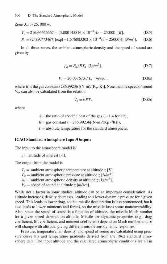
Zone 3:z> 25, 000 m,
Ta = 216.66666667 + (3.000145816 × 10⁻³)(z− 25000) [K], (D.5)
Pa = (2489.773467){exp[−1.576883202 × 10⁻⁴(z− 25000)]} [N/m2]. (D.6)
In all three zones, the ambient atmospheric density and the speed of sound aregiven by
ρa =Pa/RTa [kg/m3], (D.7)
Va = 20.037673√Ta [m/sec], (D.8a)
whereR is the gas constant (286.99236 [(N-m)/(Kp-K)]. Note that the speed of soundVa , can also be calculated from the relation
Va = kRT , (D.8b)
where
k= the ratio of specific heat of the gas (= 1.4 for air),
R= gas constant (= 286.99236[(N-m)/(Kp -◦K)]),T = absolute temperature for the standard atmosphere.
ICAO Standard Atmosphere Input/Output:
The input to the atmosphere model is
z= altitude of interest [m].
The output from the model is
Ta = ambient atmospheric temperature at altitude z [K],Pa = ambient atmospheric pressure at altitude z [N/m2],ρa = ambient atmospheric density at altitude z [kg/m3],Va = speed of sound at altitude z [m/sec].
While not a factor in some studies, altitude can be an important consideration. Asaltitude increases, density decreases, leading to a lower dynamic pressure for a givenspeed. This leads to lower drag, so that missile deceleration is less pronounced, but italso leads to lower moments and forces, so the missile loses some maneuverability.Also, since the speed of sound is a function of altitude, the missile Mach numberfor a given speed depends on altitude. Missile aerodynamic properties (e.g., dragcoefficient, lift coefficient, and moment coefficient) depend on Mach number and sowill change with altitude, giving different missile aerodynamic responses.
Pressure, temperature, air density, and speed of sound are calculated using pres-sure curve fits and temperature gradients derived from the 1962 standard atmo-sphere data. The input altitude and the calculated atmospheric conditions are all in
D The Standard Atmospheric Model 607
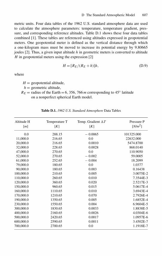
metric units. Four data tables of the 1962 U.S. standard atmosphere data are usedto calculate the atmosphere parameters: temperature, temperature gradient, pres-sure, and corresponding reference altitudes. Table D.1 shows these four data tablescombined [1]. These tables are referenced using altitudes expressed in geopotentialmeters. One geopotential meter is defined as the vertical distance through whicha one-kilogram mass must be moved to increase its potential energy by 9.80665joules [2]. Thus, a given input altitude h in geometric meters is converted to altitudeH in geopotential meters using the expression [2]
H = [RE/(RE +h)]h, (D.9)
where
H = geopotential altitude,h= geometric altitude,
RE = radius of the Earth = 6, 356, 766 m corresponding to 45◦ latitudeon a nonperfect spherical Earth model.
Table D.1. 1962 U.S. Standard Atmosphere Data Tables
Altitude H Temperature T Temp. Gradient �T Pressure P[m] [K] [K] [N/m2]
0.0 288.15 − 0.0065 101325.00011,000.0 216.65 0.0 22632.00020,000.0 216.65 0.0010 5474.870032,000.0 228.65 0.0028 868.014047,000.0 270.65 0.0 110.905052,000.0 270.65 − 0.002 59.000561,000.0 252.65 − 0.004 18.209979,000.0 180.65 0.0 1.037790,000.0 180.65 0.003 0.16438
100,000.0 210.65 0.005 3.0075E-2110,000.0 260.65 0.010 7.3544E-3120,000.0 360.65 0.020 2.5217E-3150,000.0 960.65 0.015 5.0617E-4160,000.0 1110.65 0.010 3.6943E-4170,000.0 1210.65 0.070 2.7926E-4190,000.0 1350.65 0.005 1.6852E-4230,000.0 1550.65 0.004 6.9604E-5300,000.0 1830.65 0.0033 1.8838E-5400,000.0 2160.65 0.0026 4.0304E-6500,000.0 2420.65 0.0017 1.0957E-6600,000.0 2590.65 0.0011 3.4502E-7700,000.0 2700.65 0.0 1.1918E-7
608 D The Standard Atmospheric Model
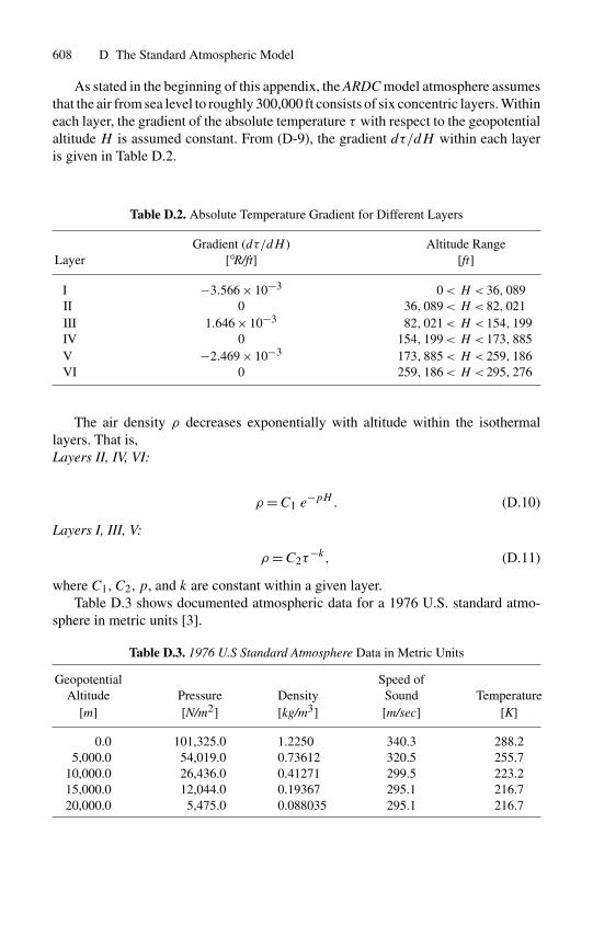
As stated in the beginning of this appendix, the ARDC model atmosphere assumesthat the air from sea level to roughly 300,000 ft consists of six concentric layers. Withineach layer, the gradient of the absolute temperature τ with respect to the geopotentialaltitude H is assumed constant. From (D-9), the gradient dτ/dH within each layeris given in Table D.2.
Table D.2. Absolute Temperature Gradient for Different Layers
Gradient (dτ/dH ) Altitude RangeLayer [◦R/ft] [ft]
I −3.566 × 10⁻³ 0< H < 36, 089II 0 36, 089< H < 82, 021III 1.646 × 10⁻³ 82, 021< H < 154, 199IV 0 154, 199< H < 173, 885V −2.469 × 10⁻³ 173, 885< H < 259, 186VI 0 259, 186< H < 295, 276
The air density ρ decreases exponentially with altitude within the isothermallayers. That is,Layers II, IV, VI:
ρ=C1 e−pH . (D.10)
Layers I, III, V:
ρ=C2τ−k, (D.11)
where C1, C2, p, and k are constant within a given layer.Table D.3 shows documented atmospheric data for a 1976 U.S. standard atmo-
sphere in metric units [3].
Table D.3. 1976 U.S Standard Atmosphere Data in Metric Units
Geopotential Speed ofAltitude Pressure Density Sound Temperature
[m] [N/m2] [kg/m3] [m/sec] [K]
0.0 101,325.0 1.2250 340.3 288.25,000.0 54,019.0 0.73612 320.5 255.7
10,000.0 26,436.0 0.41271 299.5 223.215,000.0 12,044.0 0.19367 295.1 216.720,000.0 5,475.0 0.088035 295.1 216.7

References 609
References
1. Handbook of Chemistry and Physics, 55th edition, Chemical Rubber Company, 1974,page F-191.
2. Handbook of Geophysics and Space Environment, 1985, pp.14–17.3. Airplane Aerodynamics and Performance, Roskam Aviation and Engineering Corporation,
1981, page 13.
E
Missile Classification
In much the same manner as aircraft, missiles are typed by their general characteristicgrouping. Such a grouping may show in what manner a missile is used, but it willnot identify a particular missile. This general classification makes use of three items:(1) launch environment, (2) target environment (or mission), and (3) type of vehicle.These classifications will now be discussed in more detail.
Launch Environment: Launch environment may be air, ground, underground, orunderwater. Thus the letters are A for air, G for ground, L for underground, and Ufor underwater. A more complete designation of missile launch environments is asfollows:
A - AirB - MultipleC - CoffinF - IndividualG - GroundH - Silo storedL - Silo launchedM - MobileP - Soft padR - ShipU - Underwater.
Examples of this general classification are as follows:
AIM - Air-Interceptor MissileAGM - Air-to-Ground (or Surface) MissileLGM - Silo-launched Surface-to-Surface MissileUGM - Underwater-to-Surface Missile.
A more typical example is as follows:ADM - 20A,
where A implies “air,” D “decoy,” M “guided missile,” the 20 implies the “20thdesign,” and A the “A series.”
612 E Missile Classification
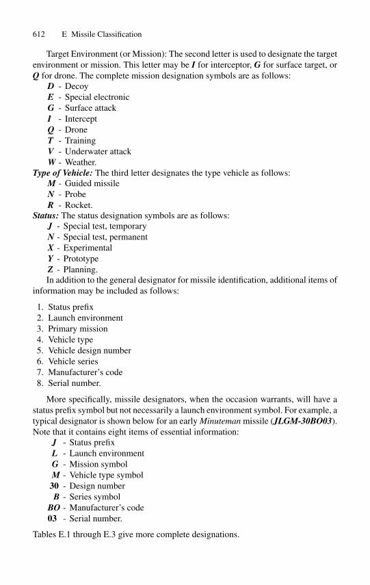
Target Environment (or Mission): The second letter is used to designate the targetenvironment or mission. This letter may be I for interceptor, G for surface target, orQ for drone. The complete mission designation symbols are as follows:
D - DecoyE - Special electronicG - Surface attackI - InterceptQ - DroneT - TrainingV - Underwater attackW - Weather.
Type of Vehicle: The third letter designates the type vehicle as follows:M - Guided missileN - ProbeR - Rocket.
Status: The status designation symbols are as follows:J - Special test, temporaryN - Special test, permanentX - ExperimentalY - PrototypeZ - Planning.In addition to the general designator for missile identification, additional items of
information may be included as follows:
1. Status prefix2. Launch environment3. Primary mission4. Vehicle type5. Vehicle design number6. Vehicle series7. Manufacturer’s code8. Serial number.
More specifically, missile designators, when the occasion warrants, will have astatus prefix symbol but not necessarily a launch environment symbol. For example, atypical designator is shown below for an early Minuteman missile (JLGM-30BO03).Note that it contains eight items of essential information:
J - Status prefixL - Launch environmentG - Mission symbolM - Vehicle type symbol
30 - Design numberB - Series symbol
BO - Manufacturer’s code03 - Serial number.
Tables E.1 through E.3 give more complete designations.
E Missile Classification 613
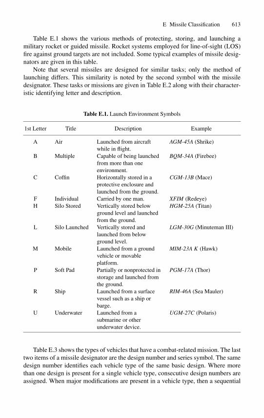
Table E.1 shows the various methods of protecting, storing, and launching amilitary rocket or guided missile. Rocket systems employed for line-of-sight (LOS)fire against ground targets are not included. Some typical examples of missile desig-nators are given in this table.
Note that several missiles are designed for similar tasks; only the method oflaunching differs. This similarity is noted by the second symbol with the missiledesignator. These tasks or missions are given in Table E.2 along with their character-istic identifying letter and description.
Table E.1. Launch Environment Symbols
1st Letter Title Description Example
A Air Launched from aircraftwhile in flight.
AGM-45A (Shrike)
B Multiple Capable of being launchedfrom more than oneenvironment.
BQM-34A (Firebee)
C Coffin Horizontally stored in aprotective enclosure andlaunched from the ground.
CGM-13B (Mace)
F Individual Carried by one man. XFIM (Redeye)H Silo Stored Vertically stored below
ground level and launchedfrom the ground.
HGM-25A (Titan)
L Silo Launched Vertically stored andlaunched from belowground level.
LGM-30G (Minuteman III)
M Mobile Launched from a groundvehicle or movableplatform.
MIM-23A K (Hawk)
P Soft Pad Partially or nonprotected instorage and launched fromthe ground.
PGM-17A (Thor)
R Ship Launched from a surfacevessel such as a ship orbarge.
RIM-46A (Sea Mauler)
U Underwater Launched from asubmarine or otherunderwater device.
UGM-27C (Polaris)
Table E.3 shows the types of vehicles that have a combat-related mission. The lasttwo items of a missile designator are the design number and series symbol. The samedesign number identifies each vehicle type of the same basic design. Where morethan one design is present for a single vehicle type, consecutive design numbers areassigned. When major modifications are present in a vehicle type, then a sequential
614 E Missile Classification
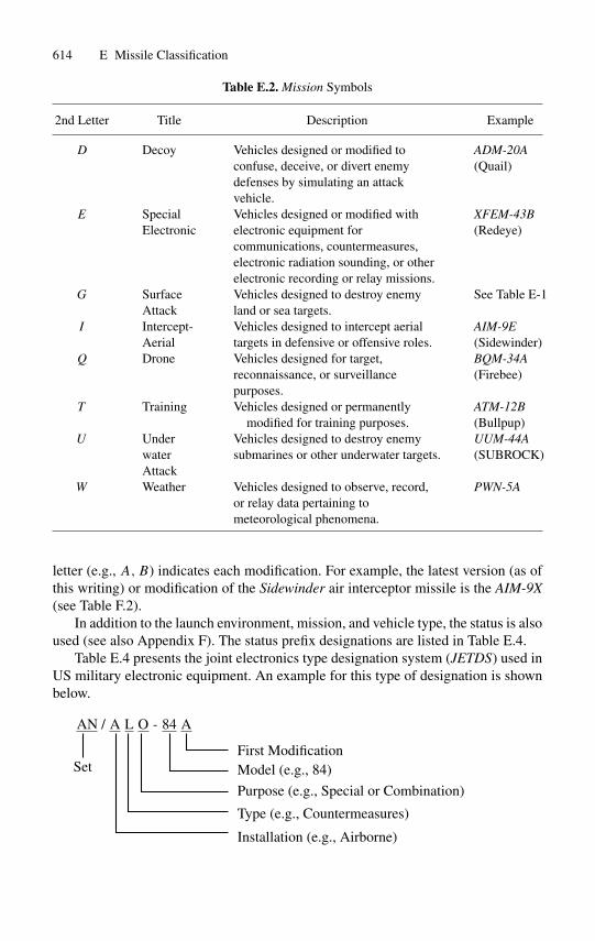
Table E.2. Mission Symbols
2nd Letter Title Description Example
D Decoy Vehicles designed or modified toconfuse, deceive, or divert enemydefenses by simulating an attackvehicle.
ADM-20A(Quail)
E SpecialElectronic
Vehicles designed or modified withelectronic equipment forcommunications, countermeasures,electronic radiation sounding, or otherelectronic recording or relay missions.
XFEM-43B(Redeye)
G SurfaceAttack
Vehicles designed to destroy enemyland or sea targets.
See Table E-1
I Intercept-Aerial
Vehicles designed to intercept aerialtargets in defensive or offensive roles.
AIM-9E(Sidewinder)
Q Drone Vehicles designed for target,reconnaissance, or surveillancepurposes.
BQM-34A(Firebee)
T Training Vehicles designed or permanentlymodified for training purposes.
ATM-12B(Bullpup)
U UnderwaterAttack
Vehicles designed to destroy enemysubmarines or other underwater targets.
UUM-44A(SUBROCK)
W Weather Vehicles designed to observe, record,or relay data pertaining tometeorological phenomena.
PWN-5A
letter (e.g., A,B) indicates each modification. For example, the latest version (as ofthis writing) or modification of the Sidewinder air interceptor missile is the AIM-9X(see Table F.2).
In addition to the launch environment, mission, and vehicle type, the status is alsoused (see also Appendix F). The status prefix designations are listed in Table E.4.
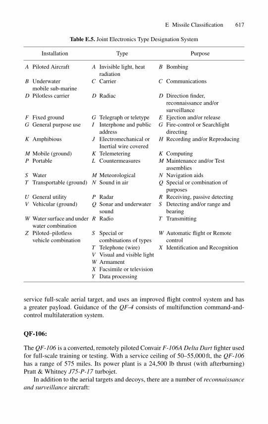
Table E.4 presents the joint electronics type designation system (JETDS) used inUS military electronic equipment. An example for this type of designation is shownbelow.
AN / A L O - 84 A
SetFirst ModificationModel (e.g., 84)
Purpose (e.g., Special or Combination)
Type (e.g., Countermeasures)
Installation (e.g., Airborne)
E Missile Classification 615
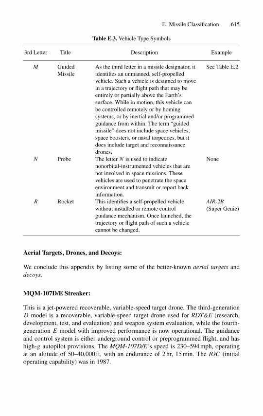
Table E.3. Vehicle Type Symbols
3rd Letter Title Description Example
M GuidedMissile
As the third letter in a missile designator, itidentifies an unmanned, self-propelledvehicle. Such a vehicle is designed to movein a trajectory or flight path that may beentirely or partially above the Earth’ssurface. While in motion, this vehicle canbe controlled remotely or by homingsystems, or by inertial and/or programmedguidance from within. The term “guidedmissile” does not include space vehicles,space boosters, or naval torpedoes, but itdoes include target and reconnaissancedrones.
See Table E.2
N Probe The letter N is used to indicatenonorbital-instrumented vehicles that arenot involved in space missions. Thesevehicles are used to penetrate the spaceenvironment and transmit or report backinformation.
None
R Rocket This identifies a self-propelled vehiclewithout installed or remote controlguidance mechanism. Once launched, thetrajectory or flight path of such a vehiclecannot be changed.
AIR-2B(Super Genie)
Aerial Targets, Drones, and Decoys:
We conclude this appendix by listing some of the better-known aerial targets anddecoys.
MQM-107D/E Streaker:
This is a jet-powered recoverable, variable-speed target drone. The third-generationD model is a recoverable, variable-speed target drone used for RDT&E (research,development, test, and evaluation) and weapon system evaluation, while the fourth-generation E model with improved performance is now operational. The guidanceand control system is either underground control or preprogrammed flight, and hashigh-g autopilot provisions. The MQM-107D/E’s speed is 230–594 mph, operatingat an altitude of 50–40,000 ft, with an endurance of 2 hr, 15 min. The IOC (initialoperating capability) was in 1987.
616 E Missile Classification
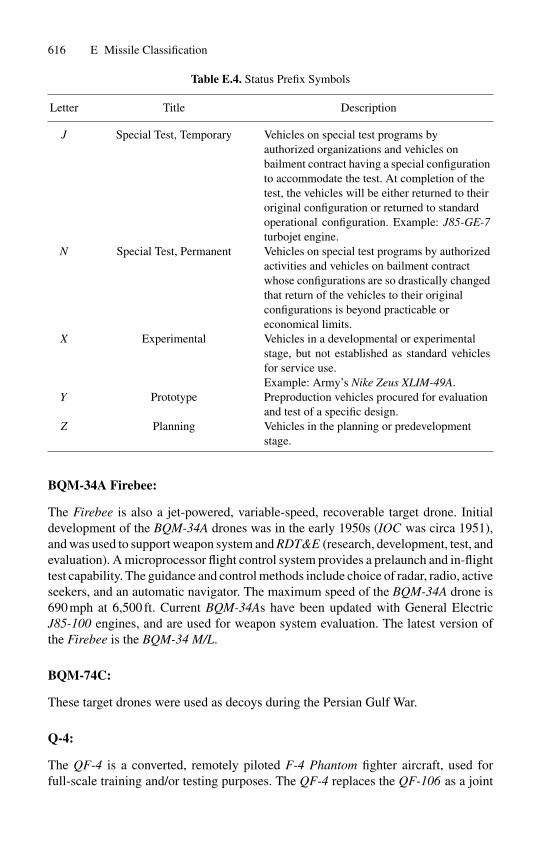
Table E.4. Status Prefix Symbols
Letter Title Description
J Special Test, Temporary Vehicles on special test programs byauthorized organizations and vehicles onbailment contract having a special configurationto accommodate the test. At completion of thetest, the vehicles will be either returned to theiroriginal configuration or returned to standardoperational configuration. Example: J85-GE-7turbojet engine.
N Special Test, Permanent Vehicles on special test programs by authorizedactivities and vehicles on bailment contractwhose configurations are so drastically changedthat return of the vehicles to their originalconfigurations is beyond practicable oreconomical limits.
X Experimental Vehicles in a developmental or experimentalstage, but not established as standard vehiclesfor service use.Example: Army’s Nike Zeus XLIM-49A.
Y Prototype Preproduction vehicles procured for evaluationand test of a specific design.
Z Planning Vehicles in the planning or predevelopmentstage.
BQM-34A Firebee:
The Firebee is also a jet-powered, variable-speed, recoverable target drone. Initialdevelopment of the BQM-34A drones was in the early 1950s (IOC was circa 1951),and was used to support weapon system and RDT&E (research, development, test, andevaluation). A microprocessor flight control system provides a prelaunch and in-flighttest capability. The guidance and control methods include choice of radar, radio, activeseekers, and an automatic navigator. The maximum speed of the BQM-34A drone is690 mph at 6,500 ft. Current BQM-34As have been updated with General ElectricJ85-100 engines, and are used for weapon system evaluation. The latest version ofthe Firebee is the BQM-34 M/L.
BQM-74C:
These target drones were used as decoys during the Persian Gulf War.
Q-4:
The QF-4 is a converted, remotely piloted F-4 Phantom fighter aircraft, used forfull-scale training and/or testing purposes. The QF-4 replaces the QF-106 as a joint
E Missile Classification 617
Table E.5. Joint Electronics Type Designation System
Installation Type Purpose
A Piloted Aircraft A Invisible light, heatradiation
B Bombing
B Underwatermobile sub-marine
C Carrier C Communications
D Pilotless carrier D Radiac D Direction finder,reconnaissance and/orsurveillance
F Fixed ground G Telegraph or teletype E Ejection and/or releaseG General purpose use I Interphone and public
addressG Fire-control or Searchlight
directingK Amphibious J Electromechanical or
Inertial wire coveredH Recording and/or Reproducing
M Mobile (ground) K Telemetering K ComputingP Portable L Countermeasures M Maintenance and/or Test
assembliesS Water M Meteorological N Navigation aidsT Transportable (ground) N Sound in air Q Special or combination of
purposesU General utility P Radar R Receiving, passive detectingV Vehicular (ground) Q Sonar and underwater
soundS Detecting and/or range and
bearingW Water surface and under
water combinationR Radio T Transmitting
Z Piloted–pilotlessvehicle combination
S Special orcombinations of types
W Automatic flight or Remotecontrol
T Telephone (wire) X Identification and RecognitionV Visual and visible lightW ArmamentX Facsimile or televisionY Data processing
service full-scale aerial target, and uses an improved flight control system and hasa greater payload. Guidance of the QF-4 consists of multifunction command-and-control multilateration system.
QF-106:
The QF-106 is a converted, remotely piloted Convair F-106A Delta Dart fighter usedfor full-scale training or testing. With a service ceiling of 50–55,000 ft, the QF-106has a range of 575 miles. Its power plant is a 24,500 lb thrust (with afterburning)Pratt & Whitney J75-P-17 turbojet.
In addition to the aerial targets and decoys, there are a number of reconnaissanceand surveillance aircraft:
618 E Missile Classification
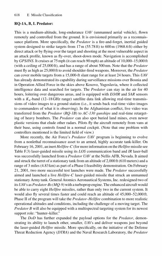
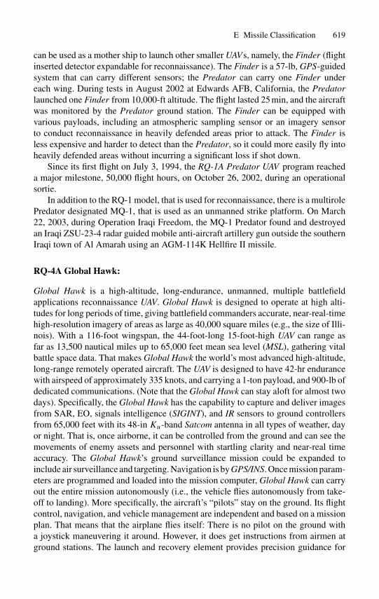
RQ-1A, B, L Predator:
This is a medium-altitude, long-endurance UAV (unmanned aerial vehicle), flownremotely and controlled from the ground. It is envisioned primarily as a reconnais-sance platform. More specifically, the Predator is a fire-and-forget, inertial guidedsystem designed to strike targets from 17 m (55.78 ft) to 600 m (1968.6 ft) either bydirect attack or by flying over the target and shooting at the most vulnerable aspect inan attack profile, known as fly-over, shoot-down mode. Navigation is accomplishedby GPS/INS. It cruises at 75 mph (it can reach 90 mph) an altitude of 10,000–15,000 ft(with a ceiling of 25,000 ft), and has a range of about 500 nm. Note that the Predatormust fly as high as 25,000 ft to avoid shoulder-fired weapons. Moreover, the Predatorcan cover mobile targets from a 15,000-ft slant range for at least 24 hours. This UAVhas already demonstrated its capability during surveillance missions over Bosnia andin Operation Allied Force in the skies above Kosovo, Yugoslavia, where it collectedintelligence data and searched for targets. The Predator can stay in the air for 40hours, loitering over dangerous areas, and is equipped with EO/IR and SAR sensorswith a Ku-band (12–18 GHz range) satellite data link allowing real-time transmis-sions of video images to a ground station (i.e., it sends back real-time video imagesto commanders of what it is observing). In the Afghanistan conflict, live video wastransferred from the Predator (RQ-1B) to AC-130 gunships and real-time retarget-ing of heavy bombers. The Predator can also spot buried land mines, even newerplastic versions that elude other radars. Pilots fly the aircraft remotely from vans attheir base, using controls found in a normal cockpit. (Note that one problem withcontrollers mentioned is the limited field of view.)
More recently, the Air Force’s Predator UAV program is beginning to evolvefrom a nonlethal reconnaissance asset to an armed, highly accurate tank-killer. OnFebruary 16, 2001, an inert Hellfire-C (for more information on the Hellfire missile seeTable F.3) laser-guided missile using its LOS communication band and IR laser-ballwas successfully launched from a Predator UAV at the Nellis AFB, Nevada. It aimedand struck the turret of a stationary tank from an altitude of 2,000 ft (610 meters) and arange of 3 miles (4.83 km) as part of a Phase I feasibility demonstration. On February21, 2001, two more successful test launches were made. The Predator successfullyaimed and launched a live Hellfire-C laser-guided missile that struck an unmannedstationary Army tank. General Atomics Aeronautical Systems, Inc. redesigned two ofits UAVs as Predator-Bs (MQ-9) with a turboprop engine. The enhanced aircraft wouldbe able to carry eight Hellfire missiles, rather than only two in the current system. Itwould also fly several times faster and could reach an altitude of 45,000–52,000 ft.Phase II of the program will take the Predator–Hellfire combination to more realisticoperational altitudes and conditions, including the challenge of a moving target. ThePredator B will also be equipped with a multispectral targeting system for its newestsupport role: “hunter–killer.”
The DoD has further expanded the payload options for the Predator, demon-strating its ability to launch other, smaller, UAVs and deliver weapons just beyondthe laser-guided Hellfire missile. More specifically, on the initiative of the DefenseThreat Reduction Agency (DTRA) and the Naval Research Laboratory, the Predator
E Missile Classification 619
can be used as a mother ship to launch other smaller UAVs, namely, the Finder (flightinserted detector expandable for reconnaissance). The Finder is a 57-lb, GPS-guidedsystem that can carry different sensors; the Predator can carry one Finder undereach wing. During tests in August 2002 at Edwards AFB, California, the Predatorlaunched one Finder from 10,000-ft altitude. The flight lasted 25 min, and the aircraftwas monitored by the Predator ground station. The Finder can be equipped withvarious payloads, including an atmospheric sampling sensor or an imagery sensorto conduct reconnaissance in heavily defended areas prior to attack. The Finder isless expensive and harder to detect than the Predator, so it could more easily fly intoheavily defended areas without incurring a significant loss if shot down.
Since its first flight on July 3, 1994, the RQ-1A Predator UAV program reacheda major milestone, 50,000 flight hours, on October 26, 2002, during an operationalsortie.
In addition to the RQ-1 model, that is used for reconnaissance, there is a multirolePredator designated MQ-1, that is used as an unmanned strike platform. On March22, 2003, during Operation Iraqi Freedom, the MQ-1 Predator found and destroyedan Iraqi ZSU-23-4 radar guided mobile anti-aircraft artillery gun outside the southernIraqi town of Al Amarah using an AGM-114K Hellfire II missile.
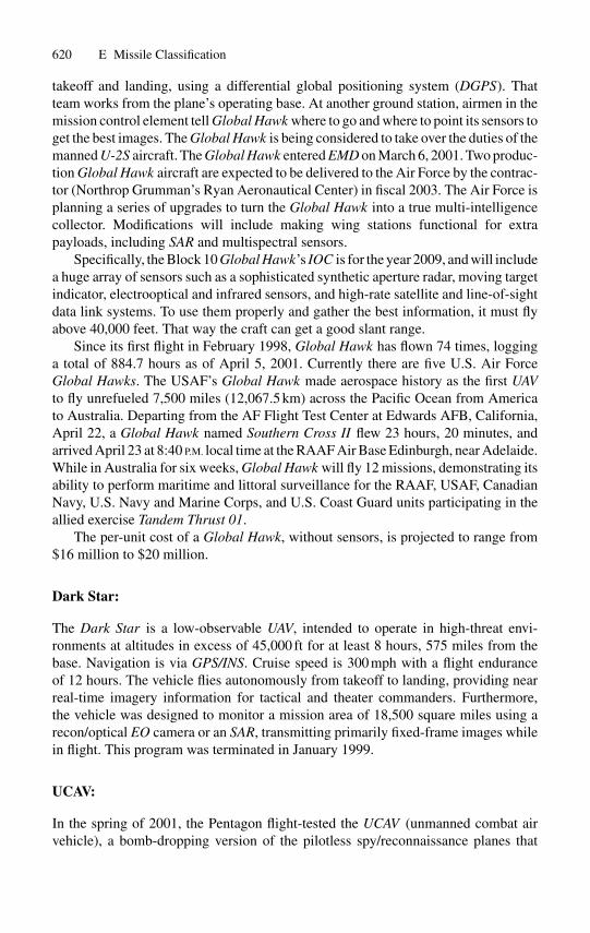
RQ-4A Global Hawk:
Global Hawk is a high-altitude, long-endurance, unmanned, multiple battlefieldapplications reconnaissance UAV. Global Hawk is designed to operate at high alti-tudes for long periods of time, giving battlefield commanders accurate, near-real-timehigh-resolution imagery of areas as large as 40,000 square miles (e.g., the size of Illi-nois). With a 116-foot wingspan, the 44-foot-long 15-foot-high UAV can range asfar as 13,500 nautical miles up to 65,000 feet mean sea level (MSL), gathering vitalbattle space data. That makes Global Hawk the world’s most advanced high-altitude,long-range remotely operated aircraft. The UAV is designed to have 42-hr endurancewith airspeed of approximately 335 knots, and carrying a 1-ton payload, and 900-lb ofdedicated communications. (Note that the Global Hawk can stay aloft for almost twodays). Specifically, the Global Hawk has the capability to capture and deliver imagesfrom SAR, EO, signals intelligence (SIGINT), and IR sensors to ground controllersfrom 65,000 feet with its 48-in Ku-band Satcom antenna in all types of weather, dayor night. That is, once airborne, it can be controlled from the ground and can see themovements of enemy assets and personnel with startling clarity and near-real timeaccuracy. The Global Hawk’s ground surveillance mission could be expanded toinclude air surveillance and targeting. Navigation is by GPS/INS. Once mission param-eters are programmed and loaded into the mission computer, Global Hawk can carryout the entire mission autonomously (i.e., the vehicle flies autonomously from take-off to landing). More specifically, the aircraft’s “pilots” stay on the ground. Its flightcontrol, navigation, and vehicle management are independent and based on a missionplan. That means that the airplane flies itself: There is no pilot on the ground witha joystick maneuvering it around. However, it does get instructions from airmen atground stations. The launch and recovery element provides precision guidance for
620 E Missile Classification
takeoff and landing, using a differential global positioning system (DGPS). Thatteam works from the plane’s operating base. At another ground station, airmen in themission control element tell Global Hawk where to go and where to point its sensors toget the best images. The Global Hawk is being considered to take over the duties of themanned U-2S aircraft. The Global Hawk entered EMD on March 6, 2001. Two produc-tion Global Hawk aircraft are expected to be delivered to the Air Force by the contrac-tor (Northrop Grumman’s Ryan Aeronautical Center) in fiscal 2003. The Air Force isplanning a series of upgrades to turn the Global Hawk into a true multi-intelligencecollector. Modifications will include making wing stations functional for extrapayloads, including SAR and multispectral sensors.
Specifically, the Block 10 Global Hawk’s IOC is for the year 2009, and will includea huge array of sensors such as a sophisticated synthetic aperture radar, moving targetindicator, electrooptical and infrared sensors, and high-rate satellite and line-of-sightdata link systems. To use them properly and gather the best information, it must flyabove 40,000 feet. That way the craft can get a good slant range.
Since its first flight in February 1998, Global Hawk has flown 74 times, logginga total of 884.7 hours as of April 5, 2001. Currently there are five U.S. Air ForceGlobal Hawks. The USAF’s Global Hawk made aerospace history as the first UAVto fly unrefueled 7,500 miles (12,067.5 km) across the Pacific Ocean from Americato Australia. Departing from the AF Flight Test Center at Edwards AFB, California,April 22, a Global Hawk named Southern Cross II flew 23 hours, 20 minutes, andarrived April 23 at 8:40 P.M. local time at the RAAF Air Base Edinburgh, near Adelaide.While in Australia for six weeks, Global Hawk will fly 12 missions, demonstrating itsability to perform maritime and littoral surveillance for the RAAF, USAF, CanadianNavy, U.S. Navy and Marine Corps, and U.S. Coast Guard units participating in theallied exercise Tandem Thrust 01.
The per-unit cost of a Global Hawk, without sensors, is projected to range from$16 million to $20 million.
Dark Star:
The Dark Star is a low-observable UAV, intended to operate in high-threat envi-ronments at altitudes in excess of 45,000 ft for at least 8 hours, 575 miles from thebase. Navigation is via GPS/INS. Cruise speed is 300 mph with a flight enduranceof 12 hours. The vehicle flies autonomously from takeoff to landing, providing nearreal-time imagery information for tactical and theater commanders. Furthermore,the vehicle was designed to monitor a mission area of 18,500 square miles using arecon/optical EO camera or an SAR, transmitting primarily fixed-frame images whilein flight. This program was terminated in January 1999.
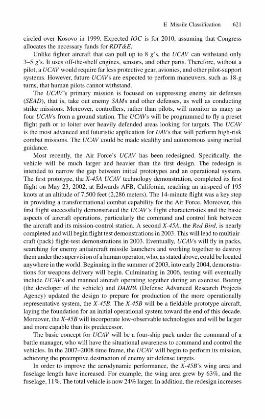
UCAV:
In the spring of 2001, the Pentagon flight-tested the UCAV (unmanned combat airvehicle), a bomb-dropping version of the pilotless spy/reconnaissance planes that
E Missile Classification 621
circled over Kosovo in 1999. Expected IOC is for 2010, assuming that Congressallocates the necessary funds for RDT&E.
Unlike fighter aircraft that can pull up to 8 g’s, the UCAV can withstand only3–5 g’s. It uses off-the-shelf engines, sensors, and other parts. Therefore, without apilot, a UCAV would require far less protective gear, avionics, and other pilot-supportsystems. However, future UCAVs are expected to perform maneuvers, such as 18-gturns, that human pilots cannot withstand.
The UCAV ’s primary mission is focused on suppressing enemy air defenses(SEAD), that is, take out enemy SAMs and other defenses, as well as conductingstrike missions. Moreover, controllers, rather than pilots, will monitor as many asfour UCAVs from a ground station. The UCAVs will be programmed to fly a presetflight path or to loiter over heavily defended areas looking for targets. The UCAVis the most advanced and futuristic application for UAVs that will perform high-riskcombat missions. The UCAV could be made stealthy and autonomous using inertialguidance.
Most recently, the Air Force’s UCAV has been redesigned. Specifically, thevehicle will be much larger and heavier than the first design. The redesign isintended to narrow the gap between initial prototypes and an operational system.The first prototype, the X-45A UCAV technology demonstration, completed its firstflight on May 23, 2002, at Edwards AFB, California, reaching an airspeed of 195knots at an altitude of 7,500 feet (2,286 meters). The 14-minute flight was a key stepin providing a transformational combat capability for the Air Force. Moreover, thisfirst flight successfully demonstrated the UCAV ’s flight characteristics and the basicaspects of aircraft operations, particularly the command and control link betweenthe aircraft and its mission-control station. A second X-45A, the Red Bird, is nearlycompleted and will begin flight test demonstrations in 2003. This will lead to multiair-craft (pack) flight-test demonstrations in 2003. Eventually, UCAVs will fly in packs,searching for enemy antiaircraft missile launchers and working together to destroythem under the supervision of a human operator, who, as stated above, could be locatedanywhere in the world. Beginning in the summer of 2003, into early 2004, demonstra-tions for weapons delivery will begin. Culminating in 2006, testing will eventuallyinclude UCAVs and manned aircraft operating together during an exercise. Boeing(the developer of the vehicle) and DARPA (Defense Advanced Research ProjectsAgency) updated the design to prepare for production of the more operationallyrepresentative system, the X-45B. The X-45B will be a fieldable prototype aircraft,laying the foundation for an initial operational system toward the end of this decade.Moreover, the X-45B will incorporate low-observable technologies and will be largerand more capable than its predecessor.
The basic concept for UCAV will be a four-ship pack under the command of abattle manager, who will have the situational awareness to command and control thevehicles. In the 2007–2008 time frame, the UCAV will begin to perform its mission,achieving the preemptive destruction of enemy air defense targets.
In order to improve the aerodynamic performance, the X-45B’s wing area andfuselage length have increased. For example, the wing area grew by 63%, and thefuselage, 11%. The total vehicle is now 24% larger. In addition, the redesign increases
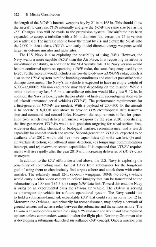
622 E Missile Classification
the length of the UCAV ’s internal weapons bay by 21 in to 168 in. This should allowthe aircraft to carry six SDBs internally and give the UCAV the same size bay as theJSF. Changes also will be made to the propulsion system. The airframe has beenexpanded to accept a turbofan with a 26-in-diameter fan, versus the 24-in versionpresently used. The increase should boost the thrust by 7% and elevate the UCAV intothe 7,000-lb-thrust class. UCAVs with early-model directed-energy weapons wouldtarget air defense missiles and radar sites.
The U.S. Navy is also exploring the possibility of using UAVs. However, theNavy wants a more capable UCAV than the Air Force. It is requesting an airbornesurveillance capability, in addition to the SEAD/strike role. The Navy version wouldfeature conformal apertures operating a UHF radar, the same frequency used by theE-2C. Furthermore, it would include a narrow-field-of-view SAR/GMI radar, which isalso on the USAF system to refine bombing coordinates and conduct poststrike battledamage assessment. The Navy’s air vehicle is expected to have an empty weight of6,000–12,000 lb. Mission endurance may vary depending on the mission. While astrike mission may last 5–6 hr, a surveillance mission would likely last 9–12 hr. Inaddition, the Navy is looking into the possibility of first- and second-generation verti-cal takeoff unmanned aerial vehicles (VTUAV ). The performance requirements fora first-generation VTUAV are modest. With a payload of 200–300 lb, the aircraftis to operate at 6,000 ft and above to provide LOS electrooptical data transmis-sion and command and control links. However, the requirements stiffen for gener-ation two, which must deliver antisurface weapons by the year 2020. Specifically,the first-generation VTUAVs would add precision targeting for naval surface fires,wide-area data relay, chemical or biological warfare, reconnaissance, and a searchcapability for combat search and rescue. Second-generation VTUAVs, expected to beavailable after 2012, would add five more capabilities: (a) strike warfare, (b) anti-air warfare detection, (c) offboard mine detection, (d) long-range communicationsintercept, and (e) overwater search capabilities. It is expected that VTUAV require-ments will rise rapidly after the year 2010 with increasing deliveries of DD-21-classdestroyers.
In addition to the UAV efforts described above, the U.S. Navy is exploring thepossibility of controlling small tactical UAVs from submarines for the long-termgoal of using them to clandestinely find targets ashore and attack them with cruisemissiles. The relatively small 12-ft (3.66-m) wingspan, 100-lb (45.36-kg) vehiclewould carry a color video camera to collect imagery that can be transmitted to thesubmarine by a 100-nm (185.3-km)-range UHF data link. Toward this end, the Navyis using on an experimental basis the Dakota air vehicle. The Dakota is servingas a surrogate air vehicle for a future operational system. The Navy would liketo field a submarine-launched, expendable UAV that could stay airborne for 12 hr.Moreover, the Dakotas, used primarily for reconnaissance, may deploy a network ofground sensors and act as a relay between the submarine and the sensors ashore. TheDakota is an autonomous air vehicle using GPS guidance and would not have requiredupdates unless commanders wanted to alter the flight plan. Northrop Grumman alsois developing a submarine-launched surveillance UAV concept. Once a mission plan
E Missile Classification 623
was uploaded on the UAV, the submarine would have been in a receive-only modein order to avoid detection through its emissions. For a future tactical version, thepayload would be refined with a limited automatic target recognition system. Ratherthan transmitting all video to the submarine, the UAV would broadcast imageryonly after recognizing a target to reduce bandwidth demands. It would also usedigital communications rather than the analog data link used in the demonstration.Finally, in order to preserve covertness, the Navy is willing to make the systemexpendable.
The U.S. Army is also studying the possibility of using its Shadow 200 tacticalunmanned aerial vehicle (T-UAV ) for signal intelligence, or Sigint. In this initial stageof the program, only an EO/IR sensor is considered as a baseline payload. Sensors willbe required to collect signals in the 20–2,000-MHz region. Operationally, the Sigint-UAV is intended to support brigade commanders. Locating an emitter would be theprimary role for the payload. Anticipated IOC for the program is in the year 2007.
EADS (European Aeronautic Defense and Space Co.) is studying a designfor a URAV in the 1,500-kg (3,307-lb) takeoff weight class. The URAV will be5.5-meters (21-ft) long with a 4.1-meter (13.5-ft) wingspan and have low-observablerequirements. The URAV would operate similarly to a recoverable cruise missile witha data link to a ground control station.
It is conceivable that future strike forces will include a mix of unmanned combatair vehicles and manned aircraft. UCAVs offer such strengths as persistence, expand-ability and stealth.
Miniature Air Launched Decoy (MALD):
DARPA (Defense Advanced Research Projects Agency) is in the process of transfer-ring the MALD technology demonstration follow-on program to the Air Force’s lethalSEAD program office. MALD is being developed to provide Air Combat Commandwith the ability to achieve air superiority by confusing enemy air defense systems.The 91-in (2.31-m) decoy is designed to fly autonomously to simulate the missionprofiles of typical fighter aircraft with the ability to maneuver through high-g turns,climbs, and dives. MALD is equipped with a signature augmentation subsystem, whichprovides active augmentation to the vehicle’s radar cross section across VHF, UHF,and microwave frequencies to replicate a tactical fighter when viewed by enemy radarsystems.
A MALD variant (or derivative) is a supersonic miniature air-launched interceptor(Mali) to defeat cruse missiles. It is being built by DARPA, which also sponsoredMALD’s development. Mali would be cued by a surveillance aircraft, such as an E-3AWACS, which would provide target updates while the interceptor flies supersonicallytoward a target that could be as far away as 200 nm (371 km). Once close to the cruisemissile, Mali would activate its Stinger seeker and engage the target from the rear atsubsonic speeds. (The USAF terminated the MALD program in January 2002.)
Other nations are also involved in R&D of UAVs. For example, Saab Aerospace(Avionics and Dynamics Division) is conducting wind tunnel tests of a low-signatureUAV designed for attack missions under the framework of Sweden’s National

624 E Missile Classification
Aeronautics Research Program. Other areas being studied include (a) productionengineering, (b) propulsion systems, (c) strength, (d) radar, and (e) IR signatures andweapons separation. Finally, NATO countries operate a number of UAVs such as theExdrome and Hunter.
F
Past and Present Tactical/Strategic Missile Systems
F.1 Historical Background
Immediately following the closing phase of World War II, and in particular in 1950with the involvement in the Korean conflict, the United States embarked on a crashprogram of missile research and development. Some of these missiles, in particularthose developed in the years 1950–1964, are listed in Table F.1.
Most of these missiles are no longer in current inventories. They are presentedhere from a historical perspective. Those that still are in the inventory, for examplethe Sidewinder and Sparrow III, have advanced state-of-the-art guidance systems.Therefore, all of the missile programs that have come and gone have served as a basisfor the constantly improving research and development programs for the currentmissiles.
The research program is a continuing process, not only for the production ofmissiles, but also for the many individual system components. The program ofcomponent research is based on realizing major aims and overcoming problems thatare inherent in the development of dependable solid-rocket motors that provide reli-able high-altitude, supersonic operation.
Some of the earlier (1947–1956) USAF/ARMY guided missile popular namesare the following:
Guided Missile NameTM-61B MatadorSM-62 SnarkGAM-63 RascalSM-64 NavahoSM-65 AtlasGAM-67 CrossbowIM-99 (69) BomarcGAR-1 FalconSAM-N-6 Talos (Army/Navy)SAM-A-7 Nike (Army)SSM-A-17 Corporal (Army).
626 F Past and Present Tactical/Strategic Missile Systems
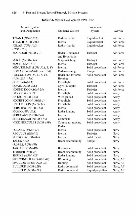
Table F.1. Missile Development 1950–1964
Missile System Propulsionand Designation Guidance System System Service
TITAN I (HGM-25A) Radio–Inertial Liquid rocket Air ForceTITAN II (LGM-25C) Inertial Liquid rocket Air ForceATLAS (CGM-16D) Radio–Inertial Liquid rocket Air Force(HGM-16F)MATADOR (MGM-1C) Radar–Command Turbojet Air Force
and HyperbolicMACE (MGM-13A) Map-matching Turbojet Air ForceMACE (CGM-13B) Inertial Turbojet Air ForceMINUTEMAN (LGM-30A, B, F) Inertial Solid propellant Air ForceBOMARC (CIM-10A, and 10B) Radar–homing Ramjet Air ForceFALCON (AIM-4A, C, E, F), Radar and Infrared Solid propellant Air Force(AIM-26A, 47A) HomingGENIE (AIR-2A) Free-flight Solid propellant Air ForceQUAIL (ADM-20C) Gyro–autopilot Turbojet Air ForceHOUND DOG (AGM-28) Inertial Turbojet Air ForceDAVY CROCKET Free-flight Solid propellant ArmyENTAC (MGM-32A) Wire-guided Solid propellant ArmyHONEST JOHN (MGR-1) Free-flight Solid propellant ArmyLITTLE JOHN (MGR-3A) Free-flight Solid propellant ArmyPERSHING (MGM-31A) Inertial Solid propellant ArmyHAWK (MIM-23A) Radar-homing Solid propellant ArmySERGEANT (MGM-29A) Inertial Solid propellant ArmySHILLELAGH (MGM-51A) Command Solid propellant ArmyNIKE-HERCULES (MIM-14B) Command-tracking Solid propellant Army
RadarPOLARIS (UGM-27) Inertial Solid propellant NavyREGULUS (RGM-6) Inertial Turbojet NavySUBROC (UUM-44A) Inertial Solid rocket NavyTALOS ARM Beam-rider homing Ramjet Navy(RIM-8E, RGM-8H)TARTAR (RIM-24B) Beam-rider Solid propellant NavyTERRIER (RIM-2E) Beam-rider homing Solid propellant NavySHRIKE (AGM-45A) Radar-homing Solid propellant NavySIDEWINDER 1-C (AIM-9D) IR homing Solid propellant Navy, AFSPARROW III-6B (AIM-7E) Homing Solid propellant Navy, AFBULLPUP (AGM-12B) Radio command Solid propellant Navy, AFBULLPUP (AGM-12C) Radio command Liquid propellant Navy, AF

F.1 Historical Background 627
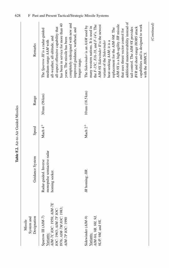
Tables F.2 through F.7 summarize the development and classification of someof the modern U.S. tactical/strategic guided weapon systems. However, it should benoted that some of these have been phased out and replaced with more advancedstate-of-the-art guidance and propulsion systems. Reliability of the guidance systemsis always a primary subject for research. The major effort is for improvement ofcomponents of inertial systems, microelectronics, star trackers, and radar and infraredhoming systems. The introduction of lasers, fiber optics, the global positioning system,etc., opened up a new field for highly accurate guidance systems as demonstrated inOperation Desert Storm in 1991, and in Yugoslavia in 1999. For more details on pastand present guided weapons, the reader is referred to [2],[3],[4].
628 F Past and Present Tactical/Strategic Missile SystemsTa
ble
F.2.
Air
-to-
Air
Gui
ded
Mis
sile
s
Mis
sile
Syst
eman
dD
esig
natio
nG
uida
nce
Syst
emSp
eed
Ran
geR
emar
ks
Spar
row
III
(AIM
-7)
Var
iant
s:A
IM-7
CIO
C:1
958;
AIM
-7E
IOC
:196
3;A
IM-7
FIO
C:
l976
;AIM
-7M
IOC
:198
3;A
IM-7
PIO
C:1
990
Rad
ar-g
uide
d.In
vers
em
onop
ulse
sem
iact
ive
rada
rho
min
gse
eker
.
Mac
h4+
30nm
(56
km)
The
Spar
row
III
isa
rada
r-gu
ided
med
ium
-ran
geA
AM
with
all-
wea
ther
,all-
altit
ude,
and
all-
aspe
ctof
fens
ive
capa
bilit
yth
atha
sbe
enin
serv
ice
for
mor
eth
an40
year
s.T
hem
issi
leha
sbe
enco
mpl
etel
yre
desi
gned
with
new
and
impr
oved
guid
ance
,war
head
,and
long
erra
nge.
Side
win
der
(AIM
-9)
Var
iant
s:A
IM-9
A,9
B,9
H,9
J,9L
/P,9
M,a
nd9X
.
IRho
min
g;II
R.
Mac
h2+
10nm
(18.
5km
)T
heSi
dew
inde
ris
anA
AM
used
bym
any
wes
tern
natio
ns.I
tis
used
inth
eF
-15C
,F/A
-18,
and
F-1
4’s.
The
AIM
-9X
Side
win
der
IIis
the
new
est
vari
anto
fth
eSi
dew
inde
rhe
at-s
eeki
ngA
AM
;iti
sa
repl
acem
entf
orth
eA
IM-9
M.T
heA
IM-9
Xis
ahi
gh-a
gilit
yII
Rm
issi
leth
atus
esth
rust
vect
orco
ntro
lfor
addi
tiona
lman
euve
rabi
lity
inst
ead
ofta
il-co
ntro
l.T
heA
IM-9
Xpr
ovid
esB
VR
and
shor
t-ra
nge
HO
BS
atta
ckca
pabi
litie
san
dis
desi
gned
tow
ork
with
the
JHM
CS.
(Con
tinu
ed)
F.1 Historical Background 629
Tabl
eF.
2.(C
onti
nued
)
Mis
sile
Syst
eman
dD
esig
natio
nG
uida
nce
Syst
emSp
eed
Ran
geR
emar
ks
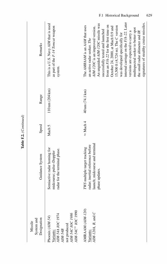
Phoe
nix
(AIM
-54)
Var
iant
s:A
IM-5
4AIO
C19
74A
IM-5
4Bno
tpro
duce
dA
IM-5
4CIO
C19
86A
IM-5
4C+
IOC
1990
Sem
iact
ive
rada
rho
min
gfo
rm
idco
urse
;pul
se–D
oppl
erra
dar
for
the
term
inal
phas
e.
Mac
h5
110
nm(2
04km
)T
his
isa
U.S
.Nav
yA
IMth
atis
used
aspa
rtof
the
F-1
4To
mca
twea
pon
syst
em.
AM
RA
AM
(AIM
-120
)V
aria
nts:
AIM
-120
A,B
,and
C
TW
Sm
ultip
leta
rget
trac
king
rada
r;in
ertia
lref
eren
cebe
fore
laun
ch;m
idco
urse
and
term
inal
phas
eup
date
s.
≈M
ach
440
nm(7
4.1
km)
The
AM
RA
AM
isan
AA
Mth
atus
esan
activ
era
dar
seek
er.T
heA
IM-1
20C
isan
impr
oved
vers
ion.
An
ungu
ided
AIM
-120
Cm
issi
lew
assu
cces
sful
lyte
sted
and
laun
ched
from
anF
/A-2
2fo
rth
efir
sttim
eon
Oct
ober
24,2
000,
atM
ach
0.9
and
15,5
00ft
(4,7
24m
).T
heC
vers
ion
was
deve
lope
dsp
ecifi
cally
for
inte
rnal
carr
iage
onth
eF
/A-2
2.L
ater
vers
ions
are
expe
cted
toca
rry
am
ultis
pect
rals
eeke
rto
bette
rsp
otth
esm
allr
adar
altim
eter
and
IRsi
gnat
ures
ofst
ealth
ycr
uise
mis
sile
s.
630 F Past and Present Tactical/Strategic Missile SystemsTa
ble
F.3.
Air
-to-
Surf
ace
Gui
ded
Mis
sile
s
Mis
sile
Syst
eman
dD
esig
natio
nG
uida
nce
Syst
emSp
eed
Ran
geR
emar
ks
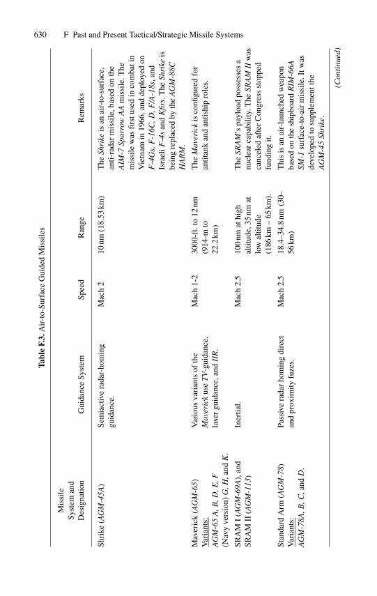
Shri
ke(A
GM
-45A
)Se
mia
ctiv
era
dar-
hom
ing
guid
ance
.M
ach
210
nm(1
8.53
km)
The
Shri
keis
anai
r-to
-sur
face
,an
ti-ra
dar
mis
sile
,bas
edon
the
AIM
-7Sp
arro
wA
Am
issi
le.T
hem
issi
lew
asfir
stus
edin
com
bati
nV
ietn
amin
1966
,and
depl
oyed
onF
-4G
s,F
-16C
,D,F
/A-1
8s,a
ndIs
rael
iF-4
san
dK
firs.
The
Shri
keis
bein
gre
plac
edby
the
AG
M-8
8CH
AR
M.
Mav
eric
k(A
GM
-65)
Var
iant
s:A
GM
-65
A,B
,D,E
,F(N
avy
vers
ion)
G,H
,and
K.
Var
ious
vari
ants
ofth
eM
aver
ick
use
TV
-gui
danc
e,la
ser
guid
ance
,and
IIR
.
Mac
h1-
230
00-f
t.to
12nm
(914
-mto
22.2
km)
The
Mav
eric
kis
confi
gure
dfo
ran
titan
kan
dan
tishi
pro
les.
SRA
MI
(AG
M-6
9A),
and
SRA
MII
(AG
M-1
13)
Iner
tial.
Mac
h2.
510
0nm
athi
ghal
titud
e,35
nmat
low
altit
ude
(186
km–
65km
).
The
SRA
M’s
payl
oad
poss
esse
sa
nucl
ear
capa
bilit
y.T
heSR
AM
IIw
asca
ncel
edaf
ter
Con
gres
sst
oppe
dfu
ndin
git.
Stan
dard
Arm
(AG
M-7
8)V
aria
nts:
AG
M-7
8A,B
,C,a
ndD
.
Pass
ive
rada
rho
min
gdi
rect
and
prox
imity
fuze
s.M
ach
2.5
18.4
–34.
8nm
(30–
56km
)T
his
isan
air-
laun
ched
wea
pon
base
don
the
ship
boar
dR
IM-6
6ASM
-1su
rfac
e-to
-air
mis
sile
.Itw
asde
velo
ped
tosu
pple
men
tthe
AG
M-4
5Sh
rike
.
(Con
tinu
ed)
F.1 Historical Background 631Ta
ble
F.3.
(Con
tinu
ed)
Mis
sile
Syst
eman
dD
esig
natio
nG
uida
nce
Syst
emSp
eed
Ran
geR
emar
ks
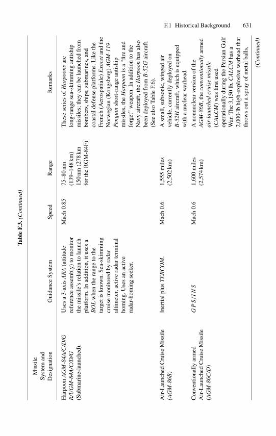
Har
poon
AG
M-8
4A/C
/D/G
R/U
GM
-84A
/C/D
/G(S
ubm
arin
e-la
unch
ed).
Use
sa
3-ax
isA
RA
(atti
tude
refe
renc
eas
sem
bly)
tom
onito
rth
em
issi
le’s
rela
tion
tola
unch
plat
form
.In
addi
tion,
itus
esa
BO
Lw
hen
the
rang
eto
the
targ
etis
know
n.Se
a-sk
imm
ing
crui
sem
onito
red
byra
dar
altim
eter
,act
ive
rada
rte
rmin
alho
min
g.U
ses
anac
tive
rada
r-ho
min
gse
eker
.
Mac
h0.
8575
–80
nm(1
39–1
48km
)15
0nm
(278
kmfo
rth
eR
GM
-84F
)
The
sese
ries
ofH
arpo
ons
are
long
-ran
gese
a-sk
imm
ing
antis
hip
mis
sile
s;th
eyca
nbe
laun
ched
from
bom
bers
,shi
ps,s
ubm
arin
es,a
ndco
asta
ldef
ense
plat
form
s.L
ike
the
Fren
ch(A
eros
patia
le)
Exo
ceta
ndth
eN
orw
egia
n(K
ongs
berg
)A
GM
-119
Peng
uin
shor
t-ra
nge
antis
hip
mis
sile
s,th
eH
arpo
onis
a“fi
rean
dfo
rget
”w
eapo
n.In
addi
tion
toth
eN
avy
airc
raft
,the
Har
poon
has
also
been
depl
oyed
from
B-5
2Gai
rcra
ft.
(See
also
Tabl
eF.
6).
Air
-Lau
nche
dC
ruis
eM
issi
le(A
GM
-86B
)In
ertia
lplu
sT
ER
CO
M.
Mac
h0.
61,
555
mile
s(2
,502
km)
Asm
all,
subs
onic
,win
ged
air
vehi
cle,
curr
ently
depl
oyed
onB
-52H
airc
raft
,whi
chis
equi
pped
with
anu
clea
rw
arhe
ad.
Con
vent
iona
llyar
med
Air
-Lau
nche
dC
ruis
eM
issi
le(A
GM
-86C
/D)
GPS/INS
Mac
h0.
61,
600
mile
s(2
,574
km)
Ano
nnuc
lear
vers
ion
ofth
eA
GM
-86B
,the
conv
enti
onal
lyar
med
air-
laun
ched
crui
sem
issi
le(C
AL
CM
)w
asfir
stus
edop
erat
iona
llydu
ring
the
Pers
ian
Gul
fW
ar.T
he3,
150
lb.C
AL
CM
has
a2,
000-
lbhi
gh-e
xplo
sive
war
head
that
thro
ws
outa
spra
yof
met
alba
lls,
(Con
tinu
ed)
632 F Past and Present Tactical/Strategic Missile Systems
Tabl
eF.
3.(C
onti
nued
)
Mis
sile
Syst
eman
dD
esig
natio
nG
uida
nce
Syst
emSp
eed
Ran
geR
emar
ks
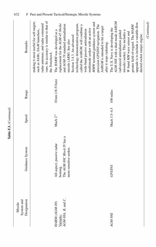
mak
ing
itm
ostu
sefu
lfor
soft
targ
ets
such
asSA
Ms,
SAsM
laun
cher
s,ra
dar
ante
nnas
,and
rada
rco
mm
and
vans
.Its
accu
racy
issi
mila
rto
that
ofth
eTo
mah
awk.
HA
RM
(AG
M-8
8)V
aria
nts:
AG
M-8
8A,B
,and
C.
All-
aspe
ct,p
assi
vera
dar
hom
ing.
The
AG
M-8
8CB
lock
IVha
sa
mor
ese
nsiti
vese
eker
.
Mac
h2+
10nm
(18.
53km
)T
heH
AR
Mw
asde
velo
ped
asa
repl
acem
entf
orth
eA
GM
-45
Shri
kean
dA
GM
-78
stan
dard
antir
adia
tion
mis
sile
(AR
M).
See
also
Sect
ion
3.4.
3.A
nad
vanc
edte
chno
logy
dem
onst
ratio
npr
ogra
m,
calle
dth
eA
AR
GM
,will
com
bine
aw
ide-
band
pass
ive
antir
adia
tion
mul
timod
ese
eker
with
anac
tive
MM
Wte
rmin
algu
idan
cesy
stem
and
prec
isio
nG
PS/
INS
navi
gatio
n.T
heA
AR
GM
isin
tend
edto
hita
targ
etaf
ter
itst
ops
radi
atin
g.
AG
M-8
8EG
PS/
INS
Mac
h3.
5–4.
510
0m
iles
The
U.S
.Nav
yis
deve
lopi
ngth
eA
GM
-88E
with
adu
alm
ode
AA
RG
M(a
dvan
ced
antir
adia
tion
guid
edm
issi
le)
seek
er.T
his
incl
udes
aW
-ban
dM
Mw
ave
sens
oran
dgr
eate
rfie
ld-o
f-re
gard
.The
HA
RM
upgr
ade
isto
incl
ude
ava
riab
le-fl
owdu
cted
rock
etra
mje
teng
ine.
(Con
tinu
ed)
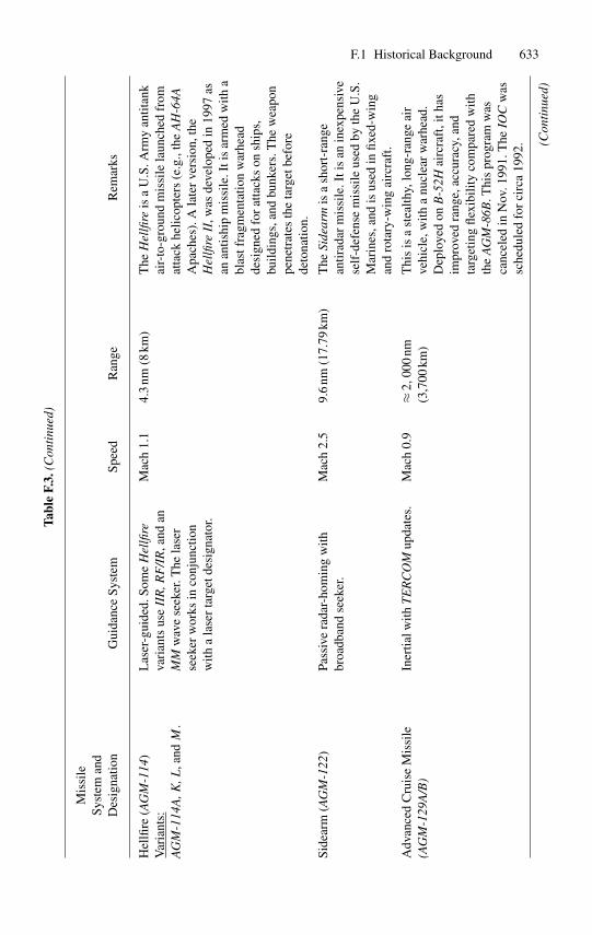
F.1 Historical Background 633Ta
ble
F.3.
(Con
tinu
ed)
Mis
sile
Syst
eman
dD
esig
natio
nG
uida
nce
Syst
emSp
eed
Ran
geR
emar
ks
Hel
lfire
(AG
M-1
14)
Var
iant
s:A
GM
-114
A,K
,L,a
ndM
.
Las
er-g
uide
d.So
me
Hel
lfire
vari
ants
use
IIR
,RF
/IR
,and
anM
Mw
ave
seek
er.T
hela
ser
seek
erw
orks
inco
njun
ctio
nw
itha
lase
rta
rget
desi
gnat
or.
Mac
h1.
14.
3nm
(8km
)T
heH
ellfi
reis
aU
.S.A
rmy
antit
ank
air-
to-g
roun
dm
issi
lela
unch
edfr
omat
tack
helic
opte
rs(e
.g.,
the
AH
-64A
Apa
ches
).A
late
rve
rsio
n,th
eH
ellfi
reII
,was
deve
lope
din
1997
asan
antis
hip
mis
sile
.Iti
sar
med
with
abl
astf
ragm
enta
tion
war
head
desi
gned
for
atta
cks
onsh
ips,
build
ings
,and
bunk
ers.
The
wea
pon
pene
trat
esth
eta
rget
befo
rede
tona
tion.
Side
arm
(AG
M-1
22)
Pass
ive
rada
r-ho
min
gw
ithbr
oadb
and
seek
er.
Mac
h2.
59.
6nm
(17.
79km
)T
heSi
dear
mis
ash
ort-
rang
ean
tirad
arm
issi
le.I
tis
anin
expe
nsiv
ese
lf-d
efen
sem
issi
leus
edby
the
U.S
.M
arin
es,a
ndis
used
infix
ed-w
ing
and
rota
ry-w
ing
airc
raft
.
Adv
ance
dC
ruis
eM
issi
le(A
GM
-129
A/B
)In
ertia
lwith
TE
RC
OM
upda
tes.
Mac
h0.
9≈
2,00
0nm
(3,7
00km
)T
his
isa
stea
lthy,
long
-ran
geai
rve
hicl
e,w
itha
nucl
ear
war
head
.D
eplo
yed
onB
-52H
airc
raft
,ith
asim
prov
edra
nge,
accu
racy
,and
targ
etin
gfle
xibi
lity
com
pare
dw
ithth
eA
GM
-86B
.Thi
spr
ogra
mw
asca
ncel
edin
Nov
.199
1.T
heIO
Cw
assc
hedu
led
for
circ
a19
92. (C
onti
nued
)
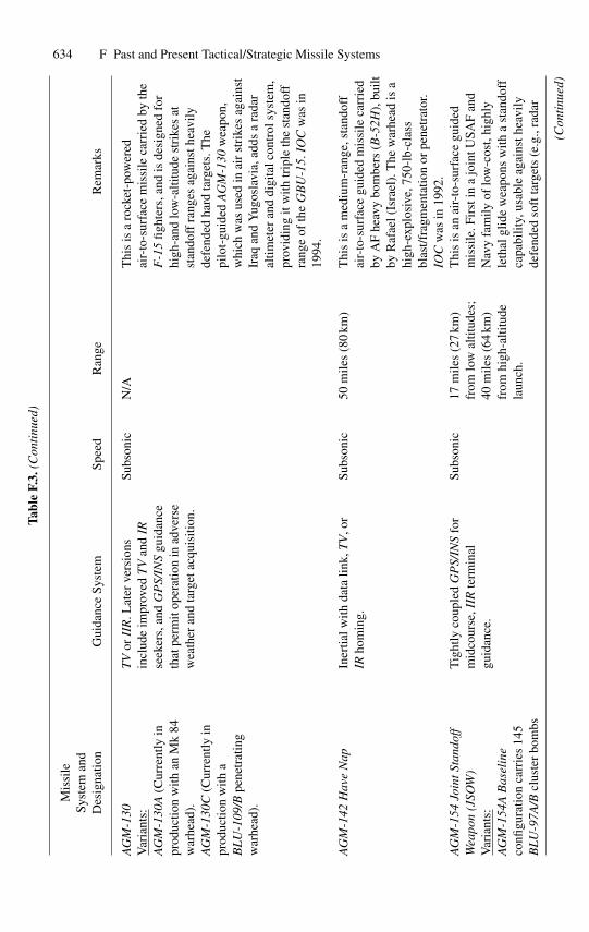
634 F Past and Present Tactical/Strategic Missile Systems
Tabl
eF.
3.(C
onti
nued
)
Mis
sile
Syst
eman
dD
esig
natio
nG
uida
nce
Syst
emSp
eed
Ran
geR
emar
ks
AG
M-1
30V
aria
nts:
AG
M-1
30A
(Cur
rent
lyin
prod
uctio
nw
ithan
Mk
84w
arhe
ad).
AG
M-1
30C
(Cur
rent
lyin
prod
uctio
nw
itha
BL
U-1
09/B
pene
trat
ing
war
head
).
TV
orII
R.L
ater
vers
ions
incl
ude
impr
oved
TV
and
IRse
eker
s,an
dG
PS/
INS
guid
ance
that
perm
itop
erat
ion
inad
vers
ew
eath
eran
dta
rget
acqu
isiti
on.
Subs
onic
N/A
Thi
sis
aro
cket
-pow
ered
air-
to-s
urfa
cem
issi
leca
rrie
dby
the
F-1
5fig
hter
s,an
dis
desi
gned
for
high
-and
low
-alti
tude
stri
kes
atst
ando
ffra
nges
agai
nsth
eavi
lyde
fend
edha
rdta
rget
s.T
hepi
lot-
guid
edA
GM
-130
wea
pon,
whi
chw
asus
edin
air
stri
kes
agai
nst
Iraq
and
Yug
osla
via,
adds
ara
dar
altim
eter
and
digi
talc
ontr
olsy
stem
,pr
ovid
ing
itw
ithtr
iple
the
stan
doff
rang
eof
the
GB
U-1
5.IO
Cw
asin
1994
.
AG
M-1
42H
ave
Nap
Iner
tialw
ithda
talin
k,T
V,o
rIR
hom
ing.
Subs
onic
50m
iles
(80
km)
Thi
sis
am
ediu
m-r
ange
,sta
ndof
fai
r-to
-sur
face
guid
edm
issi
leca
rrie
dby
AF
heav
ybo
mbe
rs(B
-52H
),bu
iltby
Raf
ael(
Isra
el).
The
war
head
isa
high
-exp
losi
ve,7
50-l
b-cl
ass
blas
t/fra
gmen
tatio
nor
pene
trat
or.
IOC
was
in19
92.
AG
M-1
54Jo
intS
tand
off
Wea
pon
(JSO
W)
Var
iant
s:A
GM
-154
AB
asel
ine
confi
gura
tion
carr
ies
145
BL
U-9
7A/B
clus
ter
bom
bs
Tig
htly
coup
led
GP
S/IN
Sfo
rm
idco
urse
,IIR
term
inal
guid
ance
.
Subs
onic
17m
iles
(27
km)
from
low
altit
udes
;40
mile
s(6
4km
)fr
omhi
gh-a
ltitu
dela
unch
.
Thi
sis
anai
r-to
-sur
face
guid
edm
issi
le.F
irst
ina
join
tUSA
Fan
dN
avy
fam
ilyof
low
-cos
t,hi
ghly
leth
algl
ide
wea
pons
with
ast
ando
ffca
pabi
lity,
usab
leag
ains
thea
vily
defe
nded
soft
targ
ets
(e.g
.,ra
dar
(Con
tinu
ed)
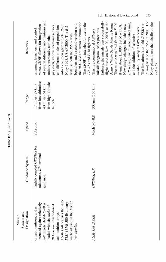
F.1 Historical Background 635
Tabl
eF.
3.(C
onti
nued
)
Mis
sile
Syst
eman
dD
esig
natio
nG
uida
nce
Syst
emSp
eed
Ran
geR
emar
ks
orsu
bmun
ition
s,an
dis
inte
nded
agai
nstr
elat
ivel
yso
ftta
rget
s.A
GM
-154
Bis
load
edw
ithsi
xst
icks
ofB
LU
-108
/Bse
nsor
-fuz
edsu
bmun
ition
arra
ys.
AG
M-1
54C
carr
ies
the
sam
eB
LU
-111
/B50
0-lb
unita
ryw
arhe
adus
edin
the
Mk
82ir
onbo
mbs
.
Tig
htly
coup
led
GP
S/IN
Sfo
rm
idco
urse
,IIR
term
inal
guid
ance
.
Subs
onic
17m
iles
(27
km)
from
low
altit
udes
;40
mile
s(6
4km
)fr
omhi
gh-a
ltitu
dela
unch
.
ante
nnas
,lau
nche
rs,a
ndco
ntro
lva
ns).
JSO
Wal
low
sfo
rin
tegr
atio
nof
seve
rald
iffe
rent
subm
uniti
ons
and
unita
ryw
arhe
ads,
nonl
etha
lpa
yloa
ds,v
ario
uste
rmin
alse
nsor
s,an
ddi
ffer
entm
odes
ofpr
opul
sion
into
aco
mm
ongl
ide
vehi
cle.
IOC
:N
avy
1998
,USA
F20
00.T
heB
-2w
illus
ebo
thth
eJS
OW
with
bom
blet
san
da
seco
ndve
rsio
nw
ithth
eB
LU
-108
antia
rmor
subm
uniti
on.
The
JSO
Wis
inte
nded
for
use
inth
eF
/A-1
8san
dF
-16
fight
ers.
AG
M-1
58JA
SSM
GP
S/IN
S,II
RM
ach
0.6–
0.8
300
nm(5
56km
)T
his
isa
conv
entio
nalA
F/N
avy
mis
sile
prog
ram
.Aft
erpr
evio
usfa
ilure
s,th
em
issi
lew
assu
cces
sful
lyfli
ghtt
este
don
Nov
.20,
2001
,att
heA
rmy’
sW
hite
Sand
sM
issi
leR
ange
.T
hem
issi
lew
asfir
edfr
oman
F-1
6fly
ing
abou
t15,
000
ftat
Mac
h0.
8.N
ewde
sign
chan
ges
incl
ude
ane
wII
Rse
eker
,new
mis
sile
cont
rolu
nit,
and
the
addi
tion
ofse
lect
ive
avai
labi
lity
antij
amG
PSre
ceiv
er.
The
first
airc
raft
tofie
ldJA
SSM
(or
Jass
m)
will
beth
eB
-52
in20
03.T
heN
avy
plan
sto
use
the
mis
sile
onth
eF
/A-1
8s.
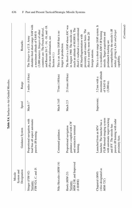
636 F Past and Present Tactical/Strategic Missile Systems
Tabl
eF.
4.Su
rfac
e-to
-Air
Gui
ded
Mis
sile
s.
Mis
sile
Syst
eman
dD
esig
natio
nG
uida
nce
Syst
emSp
eed
Ran
geR
emar
ks
Stin
ger
(FIM
-92)
Var
iant
s:F
IM-9
2A,C
,andD
.
Prop
ortio
naln
avig
atio
n,w
ithle
adbi
asal
lasp
ecta
utom
atic
pass
ive
IRho
min
g.
Mac
h1+
3m
iles
(4.8
km)
The
Stin
ger
isa
U.S
.Arm
ysh
ould
er-fi
red
shor
t-ra
nge
SAM
with
am
axim
umal
titud
eof
9,84
0ft
(3,0
00m
eter
s).S
ting
ers
ofot
her
coun
trie
sar
e:T
heFr
ench
Mis
tral
,an
dR
ussi
anSA
-7,-
14,-
16,a
nd-1
8.(F
orm
ore
info
rmat
ion,
see
Sect
ion
4.1.
)
Nik
eH
ercu
les
(MIM
-14)
Com
man
dgu
idan
ce.
Mac
h3.
6575
nm(1
40km
)T
his
isan
Arm
ySA
Mth
atis
nolo
nger
inpr
oduc
tion.
Haw
k(M
IM-2
3)V
aria
nts:
MIM
-23B
,and
Impr
oved
(I-H
AWK
)
Prop
ortio
naln
avig
atio
ngu
idan
ceco
uple
dw
ithC
Wan
dse
mia
ctiv
ete
rmin
alho
min
g.
Mac
h2.
521
.6nm
(40
km)
The
Haw
kis
aSA
Mw
hose
IOC
was
inA
ugus
t196
0.T
hem
issi
leca
nre
ach
anal
titud
eof
60,0
00ft
.The
Haw
k’s
war
head
isa
conv
entio
nal
HE
blas
t/fra
gmen
tatio
nw
ithpr
oxim
ityan
dco
ntac
tfuz
es.T
heH
awk
isus
edby
mor
eth
an20
fore
ign
natio
ns.
Cha
parr
al(M
48)
(Als
ode
sign
ated
asM
IM-7
2C)
Lau
nche
dfr
oman
M54
laun
cher
.The
laun
cher
has
aF
LIR
ther
mal
-im
agin
gsy
stem
with
auto
mat
icta
rget
trac
king
and
IFF
.The
mis
sile
has
pass
ive
IRho
min
gw
ithra
dar
prox
imity
fuze
.
Supe
rson
ic.
3.2
nmw
itha
max
imum
altit
ude
of9,
843
ft(3
,000
m).
Thi
sis
ash
ort-
rang
eSA
Msy
stem
.It
isa
mod
ified
AIM
-9IR
hom
ing
mis
sile
.Tar
geta
cqui
sitio
nan
dpo
stla
unch
trac
king
are
acco
mpl
ishe
dby
the
mis
sile
’sIR
seek
er,g
ivin
git
afir
ean
dfo
rget
capa
bilit
y.
(Con
tinu
ed)
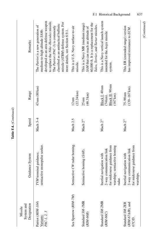
F.1 Historical Background 637Ta
ble
F.4.
(Con
tinu
ed)
Mis
sile
Syst
eman
dD
esig
natio
nG
uida
nce
Syst
emSp
eed
Ran
geR
emar
ks
Patr
iot(
MIM
-104
)V
aria
nts:
PAC
-1,2
,3
TV
Mte
rmin
algu
idan
ce;
sem
iact
ive
mon
opul
sese
eker
.M
ach
3–4
43nm
(80
km)
The
Patr
ioti
sa
new
gene
ratio
nof
med
ium
-to-
high
altit
ude
SAM
sde
velo
ped
asan
area
defe
nse
wea
pon
tore
plac
eth
eN
ike–
Her
cule
sm
issi
le.
The
Patr
iot(
PAC
-3)
isco
mm
only
clas
sifie
das
anan
titac
tical
balli
stic
mis
sile
(AT
BM
)de
fens
esy
stem
.For
mor
ede
tails
,see
Sect
ion
6.9.
1.
Sea
Spar
row
(RIM
-7M
)Se
mia
ctiv
eC
Wra
dar
hom
ing.
Mac
h2.
512
nm(2
2.24
km)
Thi
sis
aU
.S.N
avy
surf
ace-
to-a
irm
issi
le.
Stan
dard
SM-1
MR
(RIM
-66B
)Se
mia
ctiv
eho
min
g(S
AR
).M
ach
2+25
nm(4
6.3
km)
Thi
sis
aN
avy
MR
(med
ium
rang
e)SA
Mth
atca
nre
ach
anal
titud
eof
60,0
00ft
.Iti
sa
repl
acem
entf
orth
eTa
los,
Terr
ier,
and
Tart
arm
issi
les.
Stan
dard
SM-2
MR
(RIM
-66C
)In
ertia
lnav
igat
ion
with
2-w
ayco
mm
unic
atio
nlin
kfo
rm
idco
urse
guid
ance
from
war
ship
s;se
mia
ctiv
eho
min
gra
dar.
Mac
h2+
Blo
ckI:
40nm
(74
km).
Blo
ckII
: 90
nm(1
67km
).
Thi
sis
aN
avy
vert
ical
laun
chsy
stem
inte
nded
for
the
Aeg
ism
issi
lesy
stem
.
Stan
dard
SM-2
ER
(RIM
-67A
/B),
and
67C
/D.
Iner
tialn
avig
atio
nw
ith2-
way
com
mun
icat
ion
link
for
mid
cour
segu
idan
cefr
omw
arsh
ips.
Mac
h2+
75–9
0nm
(139
–167
km).
Thi
sE
R(e
xten
ded
rang
e)ve
rsio
nha
sim
prov
edre
sist
ance
toE
CM
.
(Con
tinu
ed)
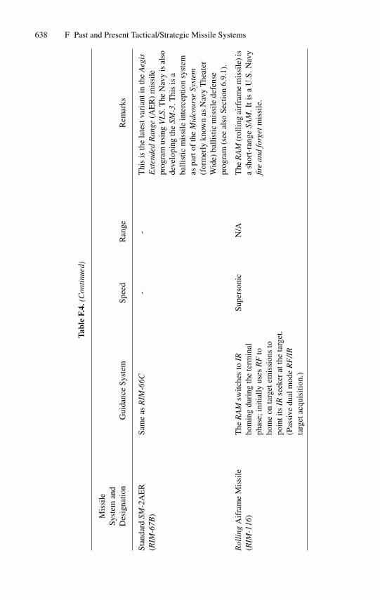
638 F Past and Present Tactical/Strategic Missile Systems
Tabl
eF.
4.(C
onti
nued
)
Mis
sile
Syst
eman
dD
esig
natio
nG
uida
nce
Syst
emSp
eed
Ran
geR
emar
ks
Stan
dard
SM-2
AE
R(R
IM-6
7B)
Sam
eas
RIM
-66C
--
Thi
sis
the
late
stva
rian
tin
the
Aeg
isE
xten
ded
Ran
ge(A
ER
)m
issi
lepr
ogra
mus
ing
VL
S.T
heN
avy
isal
sode
velo
ping
the
SM-3
.Thi
sis
aba
llist
icm
issi
lein
terc
eptio
nsy
stem
aspa
rtof
the
Mid
cour
seSy
stem
(for
mer
lykn
own
asN
avy
The
ater
Wid
e)ba
llist
icm
issi
lede
fens
epr
ogra
m(s
eeal
soSe
ctio
n6.
9.1)
.
Rol
ling
Aif
ram
eM
issi
le(R
IM-1
16)
The
RA
Msw
itche
sto
IRho
min
gdu
ring
the
term
inal
phas
e;in
itial
lyus
esR
Fto
hom
eon
targ
etem
issi
ons
topo
inti
tsIR
seek
erat
the
targ
et.
(Pas
sive
dual
mod
eR
F/I
Rta
rget
acqu
isiti
on.)
Supe
rson
icN
/AT
heR
AM
(rol
ling
airf
ram
em
issi
le)i
sa
shor
t-ra
nge
SAM
.It
isa
U.S
.Nav
yfir
ean
dfo
rget
mis
sile
.
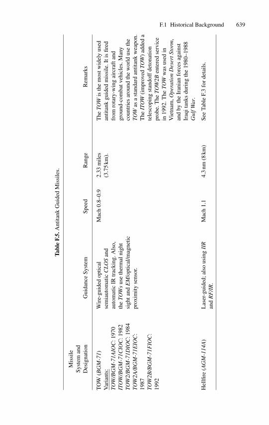
F.1 Historical Background 639
Tabl
eF.
5.A
ntita
nkG
uide
dM
issi
les.
Mis
sile
Syst
eman
dD
esig
natio
nG
uida
nce
Syst
emSp
eed
Ran
geR
emar
ks
TO
W(B
GM
-71)
Var
iant
s:TO
W/B
GM
-71A
IOC
:197
0IT
OW
/BG
M-7
1CIO
C:1
982
TOW
2/B
GM
-71D
IOC
:198
4TO
W2A
/BG
M-7
1EIO
C:
1987
TOW
2B/B
GM
-71F
IOC
:19
92
Wir
e-gu
ided
optic
alse
mia
utom
atic
CL
OS
and
auto
mat
icIR
trac
king
.Als
o,th
eTO
Ws
use
ther
mal
nigh
tsi
ghta
ndE
M/o
ptic
al/m
agne
ticpr
oxim
ityse
nsor
.
Mac
h0.
8–0.
92.
33m
iles
(3.7
5km
).T
heTO
Wis
the
mos
twid
ely
used
antit
ank
guid
edm
issi
le.I
tis
fired
from
rota
ry-w
ing
airc
raft
and
grou
nd-c
omba
tveh
icle
s.M
any
coun
trie
sar
ound
the
wor
ldus
eth
eTO
Was
ast
anda
rdan
titan
kw
eapo
n.T
heIT
OW
(im
prov
edTO
W)
adde
da
tele
scop
ing
stan
doff
deto
natio
npr
obe.
The
TOW
2Ben
tere
dse
rvic
ein
1992
.The
TOW
was
used
inV
ietn
am,O
pera
tion
Des
ertS
torm
,an
dby
the
Iran
ian
forc
esag
ains
tIr
aqit
anks
duri
ngth
e19
80–1
988
Gul
fWar
.
Hel
lfire
(AG
M-1
14A
)L
aser
-gui
ded;
also
usin
gII
Ran
dR
F/I
R.
Mac
h1.
14.
3nm
(8km
)Se
eTa
ble
F.3
for
deta
ils.
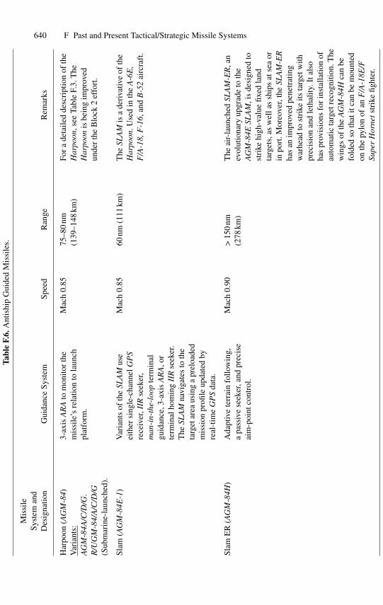
640 F Past and Present Tactical/Strategic Missile Systems
Tabl
eF.
6.A
ntis
hip
Gui
ded
Mis
sile
s.
Mis
sile
Syst
eman
dD
esig
natio
nG
uida
nce
Syst
emSp
eed
Ran
geR
emar
ks
Har
poon
(AG
M-8
4)V
aria
nts:
AG
M-8
4A/C
/D/G
.R
/UG
M-8
4/A
/C/D
/G(S
ubm
arin
e-la
unch
ed).
3-ax
isA
RA
tom
onito
rth
em
issi
le’s
rela
tion
tola
unch
plat
form
.
Mac
h0.
8575
–80
nm(1
39–1
48km
)Fo
ra
deta
iled
desc
ript
ion
ofth
eH
arpo
on, s
eeTa
ble
F.3.
The
Har
poon
isbe
ing
impr
oved
unde
rth
eB
lock
2ef
fort
.
Slam
(AG
M-8
4E-1
)V
aria
nts
ofth
eSL
AM
use
eith
ersi
ngle
-cha
nnel
GP
Sre
ceiv
er,I
IRse
eker
,m
an-i
n-th
e-lo
opte
rmin
algu
idan
ce,3
-axi
sA
RA
, or
term
inal
hom
ing
IIR
seek
er.
The
SLA
Mna
viga
tes
toth
eta
rget
area
usin
ga
prel
oade
dm
issi
onpr
ofile
upda
ted
byre
al-t
ime
GP
Sda
ta.
Mac
h0.
8560
nm(1
11km
)T
heSL
AM
isa
deri
vativ
eof
the
Har
poon
.Use
din
the
A-6
E,
F/A
-18,
F-1
6,an
dB
-52
airc
raft
.
Slam
ER
(AG
M-8
4H)
Ada
ptiv
ete
rrai
nfo
llow
ing,
apa
ssiv
ese
eker
,and
prec
ise
aim
-poi
ntco
ntro
l.
Mac
h0.
90>
150
nm(2
78km
)T
heai
r-la
unch
edSL
AM
-ER
, an
evol
utio
nary
upgr
ade
toth
eA
GM
-84E
SLA
M,i
sde
sign
edto
stri
kehi
gh-v
alue
fixed
land
targ
ets,
asw
ella
ssh
ips
atse
aor
inpo
rt.M
oreo
ver,
the
SLA
M-E
Rha
san
impr
oved
pene
trat
ing
war
head
tost
rike
itsta
rget
with
prec
isio
nan
dle
thal
ity.I
tals
oha
spr
ovis
ions
for
inst
alla
tion
ofau
tom
atic
targ
etre
cogn
ition
.The
win
gsof
the
AG
M-8
4Hca
nbe
fold
edso
that
itca
nbe
mou
nted
onth
epy
lon
ofan
F/A
-18E
/FSu
per
Hor
nets
trik
efig
hter
.
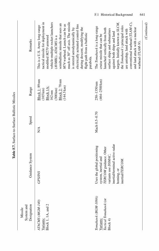
F.1 Historical Background 641Ta
ble
F.7.
Surf
ace-
to-S
urfa
ceB
allis
ticM
issi
les
Mis
sile
Syst
eman
dD
esig
natio
nG
uida
nce
Syst
emSp
eed
Ran
geR
emar
ks
ATA
CM
S(M
GM
-140
)V
aria
nts:
Blo
ck1,
1A,a
nd2
GP
S/IN
SN
/AB
lock
1:89
nm(1
65km
)B
lock
1A:
162
nm(3
00km
)B
lock
2:78
nm(1
44.5
km)
Thi
sis
aU
.S.A
rmy
long
-ran
geta
ctic
alm
issi
lefo
rde
ploy
men
tin
mod
ified
M27
0ar
mor
edve
hicl
e-m
ultip
lero
cket
laun
cher
s(A
VM
RL
).A
TAC
MS
isa
sem
ibal
listic
mis
sile
that
uses
anM
74w
arhe
ad.L
aunc
hca
nbe
asm
uch
as30
◦ off
axis
.The
mis
sile
isst
eere
dae
rody
nam
ical
lyby
elec
tric
ally
actu
ated
cont
rolfi
nsdu
ring
desc
ent,
mod
ifyi
ngth
efli
ghtp
ath
from
aba
llist
icpa
rabo
la.
Tom
ahaw
k(B
GM
-109
A)
Var
iant
s:Ta
ctic
alTo
mah
awk
(or
Blo
ck4)
Use
sth
egl
obal
posi
tioni
ngsy
stem
,ine
rtia
land
TE
RC
OM
guid
ance
.Oth
erva
rian
tsus
eD
SMA
C,
iner
tial/t
erm
inal
activ
era
dar
hom
ing,
orin
ertia
l/TE
RC
OM
.
Mac
h0.
5–0.
7025
0–13
50nm
(464
–250
0km
)T
heTo
mah
awk
isa
long
-ran
gecr
uise
mis
sile
that
can
bela
unch
edve
rtic
ally
from
both
surf
ace
ship
san
dsu
bmar
ines
agai
nstb
oth
ship
san
dla
ndta
rget
s.In
itial
lykn
own
asSL
CM
,th
eTo
mah
awk’
spr
inci
palr
oles
are
antis
hip,
land
atta
ckw
ithco
nven
tiona
lwar
head
(TL
AM
-C),
and
land
atta
ckw
itha
nucl
ear
war
head
(TL
AM
-N).
(Con
tinu
ed)
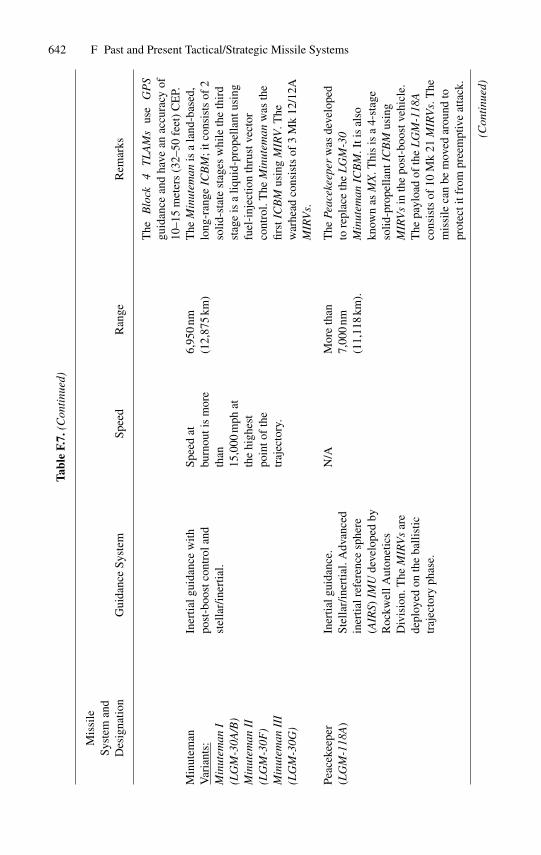
642 F Past and Present Tactical/Strategic Missile SystemsTa
ble
F.7.
(Con
tinu
ed)
Mis
sile
Syst
eman
dD
esig
natio
nG
uida
nce
Syst
emSp
eed
Ran
geR
emar
ks
The
Blo
ck4
TL
AM
sus
eG
PS
guid
ance
and
have
anac
cura
cyof
10–1
5m
eter
s(3
2–50
feet
)C
EP.
Min
utem
anV
aria
nts:
Min
utem
anI
(LG
M-3
0A/B
)M
inut
eman
II(L
GM
-30F
)M
inut
eman
III
(LG
M-3
0G)
Iner
tialg
uida
nce
with
post
-boo
stco
ntro
land
stel
lar/
iner
tial.
Spee
dat
burn
outi
sm
ore
than
15,0
00m
phat
the
high
est
poin
tof
the
traj
ecto
ry.
6,95
0nm
(12,
875
km)
The
Min
utem
anis
ala
nd-b
ased
,lo
ng-r
ange
ICB
M;i
tcon
sist
sof
2so
lid-s
tate
stag
esw
hile
the
thir
dst
age
isa
liqui
d-pr
opel
lant
usin
gfu
el-i
njec
tion
thru
stve
ctor
cont
rol.
The
Min
utem
anw
asth
efir
stIC
BM
usin
gM
IRV
.The
war
head
cons
ists
of3
Mk
12/1
2AM
IRV
s.
Peac
ekee
per
(LG
M-1
18A
)In
ertia
lgui
danc
e.St
ella
r/in
ertia
l.A
dvan
ced
iner
tialr
efer
ence
sphe
re(A
IRS)
IMU
deve
lope
dby
Roc
kwel
lAut
onet
ics
Div
isio
n.T
heM
IRV
sar
ede
ploy
edon
the
balli
stic
traj
ecto
ryph
ase.
N/A
Mor
eth
an7,
000
nm(1
1,11
8km
).
The
Peac
ekee
per
was
deve
lope
dto
repl
ace
the
LG
M-3
0M
inut
eman
ICB
M.I
tis
also
know
nas
MX
.Thi
sis
a4-
stag
eso
lid-p
rope
llant
ICB
Mus
ing
MIR
Vs
inth
epo
st-b
oost
vehi
cle.
The
payl
oad
ofth
eL
GM
-118
Aco
nsis
tsof
10M
k21
MIR
Vs.
The
mis
sile
can
bem
oved
arou
ndto
prot
ecti
tfro
mpr
eem
ptiv
eat
tack
.
(Con
tinu
ed)
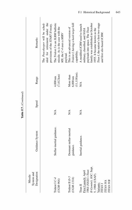
F.1 Historical Background 643
Tabl
eF.
7.(C
onti
nued
)
Mis
sile
Syst
eman
dD
esig
natio
nG
uida
nce
Syst
emSp
eed
Ran
geR
emar
ks
The
Peac
ekee
per
will
besc
hed-
uled
for
retir
emen
tun
der
the
prov
isio
nsof
the
STA
RT
IItr
eaty
.
Tri
dent
IC
-4(U
GM
-96A
)St
ella
r-in
ertia
lgui
danc
e.N
/A4,
000
nm(7
,412
km)
The
Trid
entI
isan
SLB
Mba
llist
icm
issi
le.A
sis
the
case
with
the
MX
,the
C-4
uses
aM
IRV
payl
oad.
Tri
dent
IID
-5(U
GM
-133
A)
Dor
man
tste
llar-
iner
tial
guid
ance
.N
/AM
ore
than
6,00
0nm
(11,
118
km).
Thi
sis
anad
vanc
edve
rsio
nof
Trid
entI
,hav
ing
aha
rdta
rget
kill
capa
bilit
y.
Tita
nII
Firs
tLau
nch:
Apr
il19
64(N
ASA
’sTi
tan
II-G
emin
i).I
OC
:Sep
t.5,
1988
(USA
F).
Var
iant
s:T
ITA
NI
Iner
tialg
uida
nce.
N/A
N/A
Am
odifi
edIC
BM
used
tola
unch
mili
tary
,cla
ssifi
ed,a
ndN
ASA
payl
oads
into
spac
e.T
heTi
tan
fam
ilyw
ases
tabl
ishe
din
Oct
ober
1955
.Itb
ecam
ekn
own
asth
eTi
tan
I,th
ena
tion’
sfir
sttw
o-st
age
and
first
silo
-bas
edIC
BM
.T
ITA
NIV
AT
ITA
NIV
B
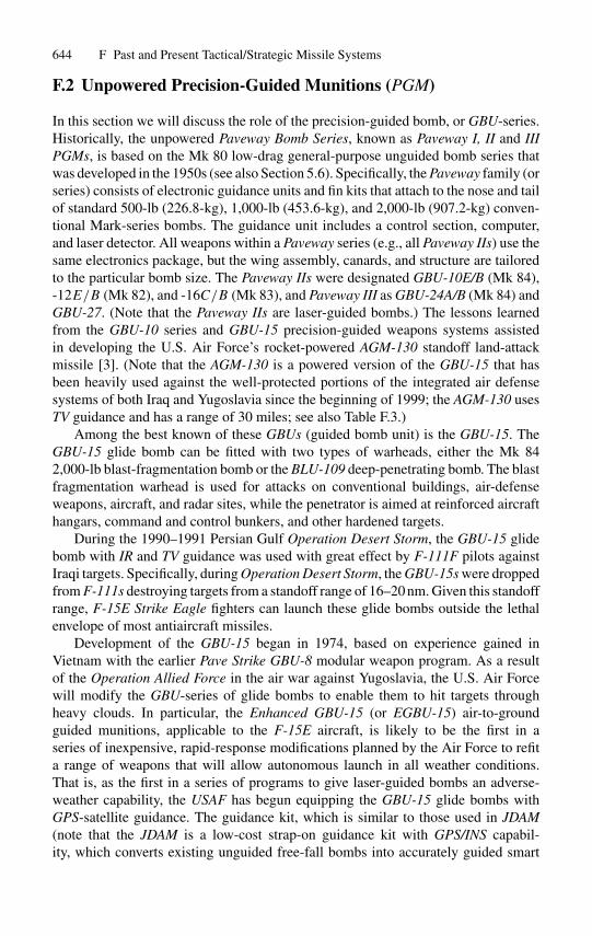
644 F Past and Present Tactical/Strategic Missile Systems
F.2 Unpowered Precision-Guided Munitions (PGM)
In this section we will discuss the role of the precision-guided bomb, or GBU-series.Historically, the unpowered Paveway Bomb Series, known as Paveway I, II and IIIPGMs, is based on the Mk 80 low-drag general-purpose unguided bomb series thatwas developed in the 1950s (see also Section 5.6). Specifically, the Paveway family (orseries) consists of electronic guidance units and fin kits that attach to the nose and tailof standard 500-lb (226.8-kg), 1,000-lb (453.6-kg), and 2,000-lb (907.2-kg) conven-tional Mark-series bombs. The guidance unit includes a control section, computer,and laser detector. All weapons within a Paveway series (e.g., all Paveway IIs) use thesame electronics package, but the wing assembly, canards, and structure are tailoredto the particular bomb size. The Paveway IIs were designated GBU-10E/B (Mk 84),-12E/B (Mk 82), and -16C/B (Mk 83), and Paveway III as GBU-24A/B (Mk 84) andGBU-27. (Note that the Paveway IIs are laser-guided bombs.) The lessons learnedfrom the GBU-10 series and GBU-15 precision-guided weapons systems assistedin developing the U.S. Air Force’s rocket-powered AGM-130 standoff land-attackmissile [3]. (Note that the AGM-130 is a powered version of the GBU-15 that hasbeen heavily used against the well-protected portions of the integrated air defensesystems of both Iraq and Yugoslavia since the beginning of 1999; the AGM-130 usesTV guidance and has a range of 30 miles; see also Table F.3.)
Among the best known of these GBUs (guided bomb unit) is the GBU-15. TheGBU-15 glide bomb can be fitted with two types of warheads, either the Mk 842,000-lb blast-fragmentation bomb or the BLU-109 deep-penetrating bomb. The blastfragmentation warhead is used for attacks on conventional buildings, air-defenseweapons, aircraft, and radar sites, while the penetrator is aimed at reinforced aircrafthangars, command and control bunkers, and other hardened targets.
During the 1990–1991 Persian Gulf Operation Desert Storm, the GBU-15 glidebomb with IR and TV guidance was used with great effect by F-111F pilots againstIraqi targets. Specifically, during Operation Desert Storm, the GBU-15s were droppedfrom F-111s destroying targets from a standoff range of 16–20 nm. Given this standoffrange, F-15E Strike Eagle fighters can launch these glide bombs outside the lethalenvelope of most antiaircraft missiles.
Development of the GBU-15 began in 1974, based on experience gained inVietnam with the earlier Pave Strike GBU-8 modular weapon program. As a resultof the Operation Allied Force in the air war against Yugoslavia, the U.S. Air Forcewill modify the GBU-series of glide bombs to enable them to hit targets throughheavy clouds. In particular, the Enhanced GBU-15 (or EGBU-15) air-to-groundguided munitions, applicable to the F-15E aircraft, is likely to be the first in aseries of inexpensive, rapid-response modifications planned by the Air Force to refita range of weapons that will allow autonomous launch in all weather conditions.That is, as the first in a series of programs to give laser-guided bombs an adverse-weather capability, the USAF has begun equipping the GBU-15 glide bombs withGPS-satellite guidance. The guidance kit, which is similar to those used in JDAM(note that the JDAM is a low-cost strap-on guidance kit with GPS/INS capabil-ity, which converts existing unguided free-fall bombs into accurately guided smart
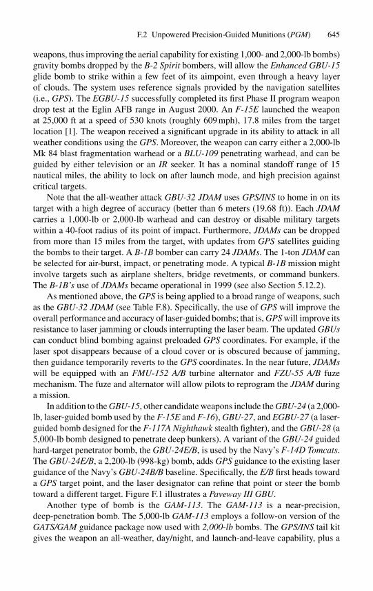
F.2 Unpowered Precision-Guided Munitions (PGM) 645
weapons, thus improving the aerial capability for existing 1,000- and 2,000-lb bombs)gravity bombs dropped by the B-2 Spirit bombers, will allow the Enhanced GBU-15glide bomb to strike within a few feet of its aimpoint, even through a heavy layerof clouds. The system uses reference signals provided by the navigation satellites(i.e., GPS). The EGBU-15 successfully completed its first Phase II program weapondrop test at the Eglin AFB range in August 2000. An F-15E launched the weaponat 25,000 ft at a speed of 530 knots (roughly 609 mph), 17.8 miles from the targetlocation [1]. The weapon received a significant upgrade in its ability to attack in allweather conditions using the GPS. Moreover, the weapon can carry either a 2,000-lbMk 84 blast fragmentation warhead or a BLU-109 penetrating warhead, and can beguided by either television or an IR seeker. It has a nominal standoff range of 15nautical miles, the ability to lock on after launch mode, and high precision againstcritical targets.
Note that the all-weather attack GBU-32 JDAM uses GPS/INS to home in on itstarget with a high degree of accuracy (better than 6 meters (19.68 ft)). Each JDAMcarries a 1,000-lb or 2,000-lb warhead and can destroy or disable military targetswithin a 40-foot radius of its point of impact. Furthermore, JDAMs can be droppedfrom more than 15 miles from the target, with updates from GPS satellites guidingthe bombs to their target. A B-1B bomber can carry 24 JDAMs. The 1-ton JDAM canbe selected for air-burst, impact, or penetrating mode. A typical B-1B mission mightinvolve targets such as airplane shelters, bridge revetments, or command bunkers.The B-1B’s use of JDAMs became operational in 1999 (see also Section 5.12.2).
As mentioned above, the GPS is being applied to a broad range of weapons, suchas the GBU-32 JDAM (see Table F.8). Specifically, the use of GPS will improve theoverall performance and accuracy of laser-guided bombs; that is, GPS will improve itsresistance to laser jamming or clouds interrupting the laser beam. The updated GBUscan conduct blind bombing against preloaded GPS coordinates. For example, if thelaser spot disappears because of a cloud cover or is obscured because of jamming,then guidance temporarily reverts to the GPS coordinates. In the near future, JDAMswill be equipped with an FMU-152 A/B turbine alternator and FZU-55 A/B fuzemechanism. The fuze and alternator will allow pilots to reprogram the JDAM duringa mission.
In addition to the GBU-15, other candidate weapons include the GBU-24 (a 2,000-lb, laser-guided bomb used by the F-15E and F-16), GBU-27, and EGBU-27 (a laser-guided bomb designed for the F-117A Nighthawk stealth fighter), and the GBU-28 (a5,000-lb bomb designed to penetrate deep bunkers). A variant of the GBU-24 guidedhard-target penetrator bomb, the GBU-24E/B, is used by the Navy’s F-14D Tomcats.The GBU-24E/B, a 2,200-lb (998-kg) bomb, adds GPS guidance to the existing laserguidance of the Navy’s GBU-24B/B baseline. Specifically, the E/B first heads towarda GPS target point, and the laser designator can refine that point or steer the bombtoward a different target. Figure F.1 illustrates a Paveway III GBU.
Another type of bomb is the GAM-113. The GAM-113 is a near-precision,deep-penetration bomb. The 5,000-lb GAM-113 employs a follow-on version of theGATS/GAM guidance package now used with 2,000-lb bombs. The GPS/INS tail kitgives the weapon an all-weather, day/night, and launch-and-leave capability, plus a
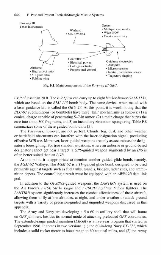
646 F Past and Present Tactical/Strategic Missile Systems
Guidance electronics• Autopilot• Microprocessor• Inertial, barometric sensor• Trajectory shaping
Seeker• Multiple scan modes• Wide IFOV• Greater sensitivity
Warhead• MK 82/83/84
Controller• Electrical power• Cold-gas actuator• Proportional control
Airframe• High aspect ratio• 5:1 glide ratio• Folding wing
Paveway IIITexas Instruments
Fig. F.1. Main components of the Paveway III GBU.
CEP of less than 20 ft. The B-2 Spirit can carry up to eight bunker-buster GAM-113s,which are based on the BLU-113 bomb body. The same device, when mated witha laser-guidance kit, is called the GBU-28. At this point, it is worth noting that theBLU-97 submunitions (or bomblets) have three "kill" mechanisms as follows: (1) aconical charge capable of penetrating 5–7-in armor, (2) a main charge that bursts thecase into about 300 fragments, and 3) an incendiary zirconium sponge ring. Table F.8summarizes some of these guided bomb units [3].
The Paveways, however, are not perfect. Clouds, fog, dust, and other weatheror battlefield obscurants can interfere with the laser-designation signal, precludingeffective LGB use. Moreover, laser-guided weapons are only as accurate as the desig-nator’s boresighting. For true standoff situations, where an airborne or ground-baseddesignator cannot get near a target, a GPS-guided weapon augmented by an INS isoften better suited than an LGB.
At this point, it is appropriate to mention another guided glide bomb, namely,the AGM-62 Walleye. The AGM-62 is a TV-guided glide bomb designed to be usedprimarily against targets such as fuel tanks, tunnels, bridges, radar sites, and ammu-nition depots. The controlling aircraft must be equipped with an AWW-9B data linkpod.
In addition to the GPS/INS-guided weapons, the LANTIRN system is used onthe Air Force’s F-15E Strike Eagle and F-16C/D Fighting Falcon fighters. TheLANTIRN system significantly increases the combat effectiveness of these aircraft,allowing them to fly at low altitudes, at night, and under weather to attack groundtargets with a variety of precision-guided and unguided weapons discussed in thisappendix.
The Army and Navy are developing a 5 × 60-in artillery shell that will homeon GPS jammers, besides its normal mode of attacking preloaded GPS coordinates.The extended-range guided munition (ERGM) is a five-year program that started inSeptember 1996. It comes in two versions: (1) the 60-in-long Navy EX-171, whichincludes a solid rocket motor to boost range to 60 nautical miles, and (2) the Army
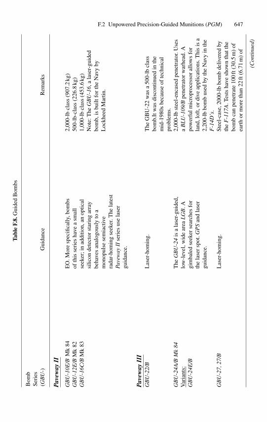
F.2 Unpowered Precision-Guided Munitions (PGM) 647
Tabl
eF.
8.G
uide
dB
ombs
Bom
bSe
ries
(GB
U-)
Gui
danc
eR
emar
ks
Pav
eway
II
GB
U-1
0E/B
Mk
84G
BU
-12E
/BM
k82
GB
U-1
6C/B
Mk
83
EO
.Mor
esp
ecifi
cally
,bom
bsof
this
seri
esha
vea
smal
lse
eker
;in
addi
tion,
anop
tical
silic
onde
tect
orst
arin
gar
ray
beha
ves
anal
ogou
sly
toa
mon
opul
sese
mia
ctiv
era
dar-
hom
ing
seek
er.T
hela
test
Pave
way
IIse
ries
use
lase
rgu
idan
ce.
2,00
0-lb
clas
s(9
07.2
kg)
500-
lb-c
lass
(226
.8kg
)1,
000-
lbcl
ass
(453
.6kg
)N
ote:
The
GB
U-1
6,a
lase
r-gu
ided
bom
b,is
built
for
the
Nav
yby
Loc
khee
dM
artin
.
Pav
eway
III
GB
U-2
2/B
Las
er-h
omin
g.T
heG
BU
-22
was
a50
0-lb
clas
sbo
mb.
Itw
asdi
scon
tinue
din
the
mid
-198
0sbe
caus
eof
tech
nica
lpr
oble
ms.
GB
U-2
4A/B
Mk
84V
aria
nts:
GB
U-2
4E/B
The
GB
U-2
4is
ala
ser-
guid
ed,
low
-lev
el,w
ide
area
LG
B.A
gim
bale
dse
eker
sear
ches
for
the
lase
rsp
ot.G
PS
and
lase
rgu
idan
ce.
2,00
0-lb
stee
l-en
case
dpe
netr
ator
.Use
sa
BL
U-1
09/B
pene
trat
orw
arhe
ad.A
pow
erfu
lmic
ropr
oces
sor
allo
ws
for
land
,lof
t,or
dive
appl
icat
ions
.Thi
sis
a2,
200-
lbbo
mb
used
byth
eN
avy
inth
eF
-14D
’s.
GB
U-2
7,27
/BL
aser
-hom
ing.
Stee
l-ca
se,2
000-
lbbo
mb
deliv
ered
byth
eF
-117
A.T
ests
have
show
nth
atth
ebo
mb
can
pene
trat
e10
0ft
(30.
5m
)of
eart
hor
mor
eth
an22
ft(6
.71
m)
of
(Con
tinu
ed)

648 F Past and Present Tactical/Strategic Missile Systems
Tabl
eF.
8.(C
onti
nued
)
Bom
bSe
ries
(GB
U-)
Gui
danc
eR
emar
ks
conc
rete
.U
sed
duri
ngth
e19
90–1
991
Pers
ian
Gul
fW
ar.
The
GB
U-2
7/B
isB
LU
-109
/Bco
mpa
tible
.
EG
BU
-27
Las
er-h
omin
gan
dG
PS/I
NS.
The
Blo
ck2
F-1
17s
upgr
ade
will
carr
yth
e2,
000-
lbE
GB
U-2
7bo
mb.
The
Blo
ck2
will
also
prov
ide
the
capa
bilit
yto
drop
2,00
0-lb
vers
ions
ofth
eJD
AM
with
both
the
pene
trat
orB
LU
-109
and
the
blas
t/fra
gmen
tatio
nM
k84
.In
the
Afg
han
confl
ictt
heA
Fus
edth
ela
test
pene
trat
ing
war
head
,nam
ely,
the
BL
U-1
18/B
.The
BL
U-1
18/B
pene
trat
ing
war
head
deto
nate
san
dge
nera
tes
high
,su
stai
ned
blas
tpre
ssur
ein
aco
nfine
dsp
ace
tom
ake
the
mak
eth
em
uniti
onm
ore
effe
ctiv
eag
ains
ttun
nels
and
cave
sth
anth
eB
LU
-109
pene
trat
orw
arhe
ad.
GB
U-2
8A/B
Las
er-h
omin
g.T
his
new
bunk
er-b
ustin
gw
eapo
nw
asde
velo
ped
(and
succ
essf
ully
used
)fo
rO
pera
tion
Des
ertS
torm
,dro
pped
byF
-111
s.G
BU
-28s
wer
eal
sous
edin
Kos
ovo,
drop
ped
byF
-15E
s.T
heG
BU
-28
isa
4,70
0-lb
(2,1
31.9
2-kg
)w
eapo
n.T
hew
arhe
adus
edis
the
BL
U-1
13/A
Bbl
astf
ragm
enta
tion.
EG
BU
-28
Las
er-h
omin
g.T
his
isan
impr
oved
,5,0
00-l
b-cl
ass
pene
trat
ing
bom
b.
GB
U-2
8B/B
GP
San
dla
ser
hom
ing.
Ital
sous
esau
toG
PS-
aide
dta
rget
ing
that
upda
tes
and
refin
esta
rget
info
rmat
ion
send
toth
ew
eapo
n.
The
GB
U-2
8B/B
isan
enha
nced
vers
ion
ofth
eG
BU
-28A
/B,
desi
gned
spec
ifica
llyfo
rth
eB
-2.T
estin
gof
the
wea
pon
bega
nin
Mar
ch20
03fir
stw
ithin
erta
ndla
ter
with
live
GB
U-2
8B/B
s.T
hew
eapo
nis
depl
oyab
lein
allw
eath
erco
nditi
ons.
The
prog
ram
issc
hedu
led
for
com
plet
ion
byth
een
dof
2004
.
GB
U-1
5U
ses
TV
orII
Rse
eker
.Tar
getin
gop
tions
incl
ude
LO
BL
and
LO
AL
.2,
000-
lbcl
ass
bom
b.U
sed
agai
nst
brid
ges,
build
ings
,bun
kers
,an
dch
emic
alpl
ants
.U
ses
aM
k84
blas
t/fra
gor
BL
U-1
09pe
netr
atin
gw
arhe
ad.T
heII
Rse
eker
has
90%
com
mon
ality
with
the
Mav
eric
kA
GM
-65D
.
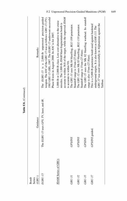
F.2 Unpowered Precision-Guided Munitions (PGM) 649
Tabl
eF.
8.(C
onti
nued
)
Bom
bSe
ries
(GB
U-)
Gui
danc
eR
emar
ks
EG
BU
-15
The
EG
BU
-15
uses
GP
S,T
V,l
aser
,and
IR.
The
EG
BU
-15
isa
2,00
0-lb
unpo
wer
edpr
ecis
ion-
guid
edw
eapo
n.T
heIO
Cof
the
GB
U-1
5w
asas
follo
ws:
GB
U-1
5(T
V),
1983
GB
U-1
5(I
IR),
1987
.The
EG
BU
-15
unde
rwen
tsuc
cess
ful
Phas
eII
test
sin
Aug
ust2
000.
Its
IOC
isfo
r20
07.
JDA
MSe
ries
ofG
BU
s1,
000-
lbor
2,00
0-lb
clas
s.L
ow-c
osta
ltern
ativ
eto
the
crui
sem
issi
les.
The
1,00
0-lb
JDA
Mbl
ast-
frag
men
tatio
nbo
mb
isac
cura
teto
with
in36
ftof
the
targ
et,w
hile
the
impr
oved
JDA
Mis
accu
rate
tow
ithin
9ft
.G
BU
-31
GP
S/IN
ST
heG
BU
-31
uses
Mk
84bl
ast/f
rag,
BL
U-1
09pe
netr
ator
.St
ando
ffra
nge
is15
nm(2
7.8
km).
GB
U-3
2G
PS/
INS
The
GB
U-3
2us
esM
k83
blas
t/fra
g,B
LU
-110
pene
trat
or.
Stan
doff
rang
eis
15nm
(27.
8km
).G
BU
-35
GP
SIN
ST
heG
BU
-35
uses
the
Mk
82bl
ast/f
rag
war
head
.It
sst
ando
ffra
nge
isal
so15
nm(2
7.8
km).
GB
U-3
7G
PS/
INS
guid
ed.
Thi
sis
a5,
000-
lbpe
netr
ator
bom
bus
edag
ains
thar
dene
dun
derg
roun
dta
rget
s.It
isal
sokn
own
asG
AM
-113
.The
GB
U-3
7w
asus
edsu
cces
sful
lyin
Afg
hani
stan
agai
nstt
heTa
liban
.
650 F Past and Present Tactical/Strategic Missile Systems
XM 172 (see also Chapter 1). The ERGM is a 12-caliber rocket-assisted projectilecarrying a four-caliber submunitions payload to ranges of about 63 nautical miles(117 km), well beyond the range of current Navy gun ranges. The 110-lb (50-kg)aerodynamic projectile is 5 in (13 cm) in length, uses a coupled GPS/INS guidancesystem, and is armed with a submunitions warhead. The GPS guidance is tightlycoupled to an inertial guidance system that will be immune to jamming, a feature thatwill enable the ERGM round to attack targets in a heavy ECM environment. The initialwarhead configuration for ERGM will consist of 72 EX-1 submunitions per round.The EX-1 is a variant of the U.S. Army-developed M80 dual-purpose conventionalmunition, which incorporates a shaped charge and an enhanced fragmentation casefor use against materiel and personnel targets. The ERGM’s submunitions will beuniformly dispensed within a predetermined area that depends upon the specific targetto be attacked and the altitude at which the submunitions are released. ERGM’s rangeand precise GPS targeting capability will improve naval surface fire support (NSFS)and provide near-term gunfire support for amphibious operations, the suppressionand destruction of hostile antishipping weapons and air-defense systems, and navalfires support to the joint land battle. Thus, the ERGM will allow ships to hit enemytargets deep ashore with concentrated fire, in support of Army and Marine units.Guidance will be provided from an inertial measurement unit (IMU). Relying onGPS satellites for accuracy, the missile will be launched from shipboard guns. Uponexiting the gun barrel, the missile’s’canards and tail fins deploy immediately to controlit to an unjammed 20-meter CEP accuracy; submunitions can be dispensed at analtitude of 250–400 meters. The ERGM, with a short time-of-flight, has 200◦/hrfiber optic gyros in the Navy version and micromachined silicon gyros in the Armyshell.
IOC is scheduled for FY 2005 and is to be deployed on later versions of theDDG-51 Arleigh Burke-class destroyer and the future DD-21 Land Attack destroyerequipped with the service’s new 5-in/0.62 caliber gun.
References
1. Airman, Vol. XLIV, Number 11, November 2000.2. Gunston, B.: The Illustrated Encyclopedia of Aircraft Armament, Orion Books, a division
of Crown Publishers, Inc., New York, 1988. (This book is out of print.)3. Laur, T.M. and Llanso, S.L.: Encyclopedia of Modern U.S. Military Weapons, edited by
Walter J. Boyne, Berkley Books, New York, 1995.4. McDaid and Oliver, D.: Smart Weapons, Welcome Rain, New York, 1997.
G
Properties of Conics
G.1 Preliminaries
It is well known that when a body is in motion under the action of an attractivecentral force that varies as the inverse square of the distance, the path described willbe a conic whose focus is at the center of attraction. The particular conic (ellipse,hyperbola, or parabola) is determined solely by the velocity and the distance from thecenter of force. In this appendix, we will consider the purely geometric problem ofdetermining the various conic paths that connect two fixed points and that have a focuscoinciding with a fixed center of force. Specifically, in this appendix we will discussthe geometric and analytic properties as applied to ballistic missile trajectories.
There are many equivalent definitions of conics; however, we shall find the follow-ing ones most convenient for our purposes [1], [2], [3]:
Ellipse:
The locus of points the sum of whose distances from two fixed points (i.e., foci) isconstant.
Hyperbola:
The locus of points the difference of whose distances from two fixed points (i.e., foci)is constant.
Parabola:
The locus of points equally distant from a fixed point (i.e., the focus) and a fixedstraight line (i.e., the directrix).
The familiar elements of these conics are shown in Figures G-1, G-2, and G-3.In Section 6.2, equation (6.1), the general equation of a conic in Cartesian coor-
dinates was given as a second-degree equation of the form [4], [5]
Ax2 +Bxy+Cy2 +Dx+Ey+F = 0. (G.1)
652 G Properties of Conics
Specifically, any equation of this form with (A,B,C) �= (0, 0, 0) corresponds to aconic section and vice versa; that is, the coefficients are assumed to be real andA2 +B2 +C2 �= 0. Equation (G-1) can also be expressed as
(p2 + q2)[(x−α)2 + (y−β)2] = e2(px+ qy+ r)2,where e is the eccentricity, (α, β) the focus, and px+ qy+ r is the equation of thedirectrix of the conic. In vertex form the equation is
y2 = 2px− (1 − ε2)x2,
where 2p is the parameter of the conic, that is, the length of its latus rectum, which inthe ellipse and hyperbola equals b2/a2 (where a and b are the lengths of the semiaxesof the conic), and ε is the numerical eccentricity, e/a; there are many other equivalentdescriptions. (Vertex is an expression for a conic, obtained by a suitable change ofvariables, in which the vertex is taken as the origin of the coordinate system, and theaxis of the conic lies along the x-axis.)
Moreover, the type of conic section is determined by the values of the characteristicequation B2 − 4AC and the discriminant [5]∣∣∣∣∣∣
A B/2 D/2B/2 C E/2D/2 E/2 F
∣∣∣∣∣∣of (G-1) is shown in Table G.2. The general quadratic equation is ax2 + bx+ c= 0with solutions
x= (−b±√b2 − 4ac)/2a.
The vanishing of b2 − 4ac, called the discriminant, is a necessary and sufficient condi-tion for equal roots. If a, b, c are all rational numbers, then the roots are real andunequal if and only if b2 − 4ac> 0. At this point, a few words about the discriminantare in order.
The discriminant is an algebraic expression, related to the coefficients of a poly-nomial equation (or to a number field), that gives information about the roots of thepolynomial; principally, the discriminant is nonzero if and only if the roots are distinct.For example,
D= b2 − 4ac
is the discriminant of the quadratic equation
ax2 + bx+ c= 0;D is positive exactly when the equation has distinct real roots, and is zero exactlywhen it has equal real roots. More precisely, the discriminant of a polynomial p ofdegree n over a given field is the quantity.
D(p)= (−1)n(n−1)/2R(p, p′),
where R is the resolvent of p and p′.
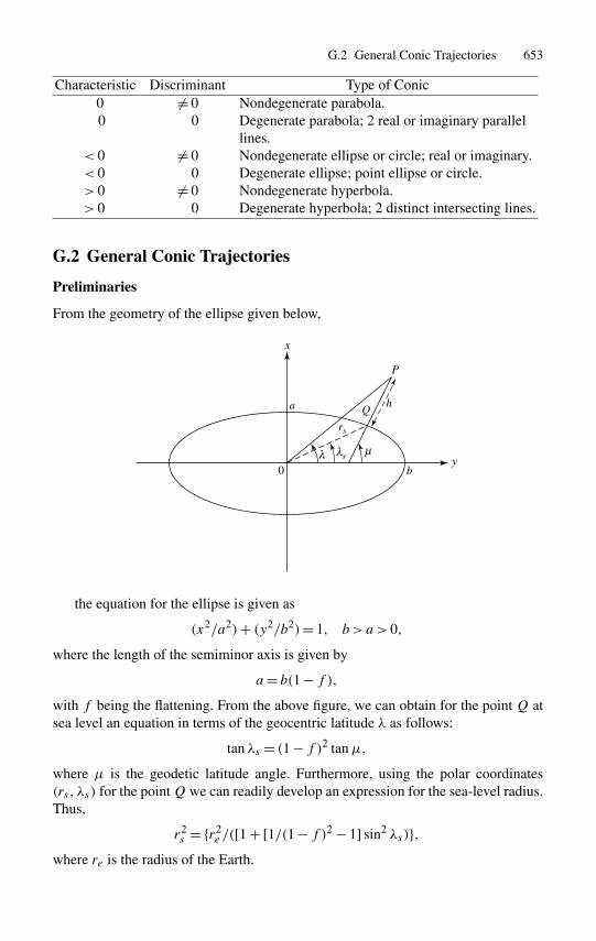
G.2 General Conic Trajectories 653
Characteristic Discriminant Type of Conic0 �= 0 Nondegenerate parabola.0 0 Degenerate parabola; 2 real or imaginary parallel
lines.< 0 �= 0 Nondegenerate ellipse or circle; real or imaginary.< 0 0 Degenerate ellipse; point ellipse or circle.> 0 �= 0 Nondegenerate hyperbola.> 0 0 Degenerate hyperbola; 2 distinct intersecting lines.
G.2 General Conic Trajectories
Preliminaries
From the geometry of the ellipse given below,
0 b
a Q
P
h
rs
s
x
yµλλ
the equation for the ellipse is given as
(x2/a2)+ (y2/b2)= 1, b > a > 0,
where the length of the semiminor axis is given by
a= b(1 − f ),with f being the flattening. From the above figure, we can obtain for the point Q atsea level an equation in terms of the geocentric latitude λ as follows:
tan λs = (1 − f )2 tanµ,
where µ is the geodetic latitude angle. Furthermore, using the polar coordinates(rs, λs) for the pointQ we can readily develop an expression for the sea-level radius.Thus,
r2s = {r2
e /([1 + [1/(1 − f )2 − 1] sin2 λs)},where re is the radius of the Earth.
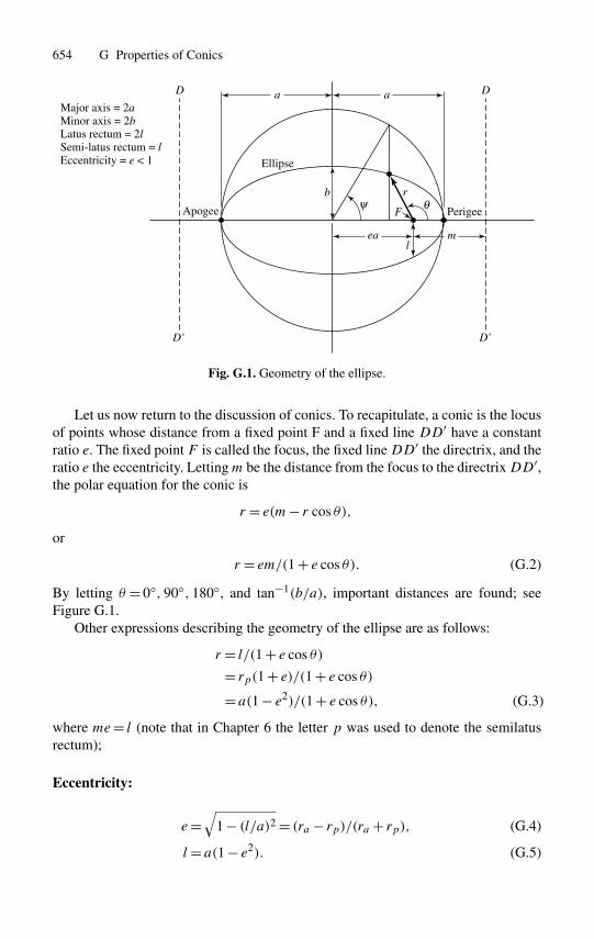
654 G Properties of Conics
ea
Ellipse
Apogee Perigee
b
lm
r
a aD D
D' D'
Fθψ
Major axis = 2aMinor axis = 2bLatus rectum = 2lSemi-latus rectum = lEccentricity = e < 1
Fig. G.1. Geometry of the ellipse.
Let us now return to the discussion of conics. To recapitulate, a conic is the locusof points whose distance from a fixed point F and a fixed line DD′ have a constantratio e. The fixed point F is called the focus, the fixed lineDD′ the directrix, and theratio e the eccentricity. Lettingm be the distance from the focus to the directrixDD′,the polar equation for the conic is
r = e(m− r cos θ),
or
r = em/(1 + e cos θ). (G.2)
By letting θ = 0◦, 90◦, 180◦, and tan−1(b/a), important distances are found; seeFigure G.1.
Other expressions describing the geometry of the ellipse are as follows:
r = l/(1 + e cos θ)
= rp(1 + e)/(1 + e cos θ)
= a(1 − e2)/(1 + e cos θ), (G.3)
where me= l (note that in Chapter 6 the letter p was used to denote the semilatusrectum);
Eccentricity:
e=√
1 − (l/a)2 = (ra − rp)/(ra + rp), (G.4)
l= a(1 − e2). (G.5)
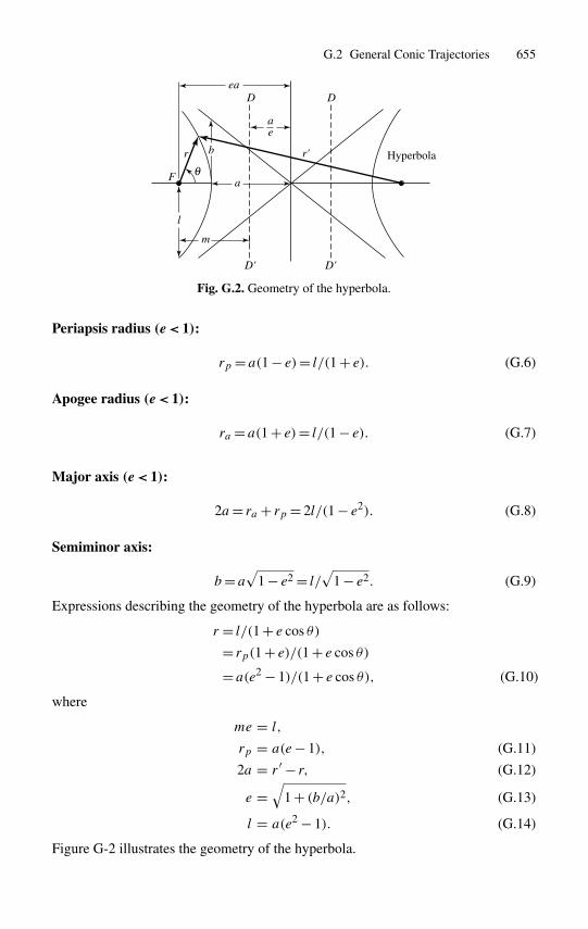
G.2 General Conic Trajectories 655
ea
b
l
m
r r'
a
a
e
D
D'
D
D'
θF
Hyperbola
Fig. G.2. Geometry of the hyperbola.
Periapsis radius (e < 1):
rp = a(1 − e)= l/(1 + e). (G.6)
Apogee radius (e < 1):
ra = a(1 + e)= l/(1 − e). (G.7)
Major axis (e < 1):
2a= ra + rp = 2l/(1 − e2). (G.8)
Semiminor axis:
b= a√
1 − e2 = l/√
1 − e2. (G.9)
Expressions describing the geometry of the hyperbola are as follows:
r = l/(1 + e cos θ)
= rp(1 + e)/(1 + e cos θ)
= a(e2 − 1)/(1 + e cos θ), (G.10)
where
me = l,
rp = a(e− 1), (G.11)
2a = r ′ − r, (G.12)
e =√
1 + (b/a)2, (G.13)
l = a(e2 − 1). (G.14)
Figure G-2 illustrates the geometry of the hyperbola.
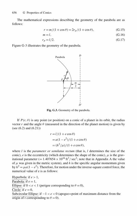
656 G Properties of Conics
The mathematical expressions describing the geometry of the parabola are asfollows:
r =m/(1 + cos θ)= 2rp/(1 + cos θ), (G.15)
m= l, (G.16)
rp = l/2. (G.17)
Figure G-3 illustrates the geometry of the parabola.
lm
D
D'
θ
m2
r
F
Parabola
Fig. G.3. Geometry of the parabola.
If P(r, θ) is any point (or position) on a conic of a planet in its orbit, the radiusvector r and the angle θ (measured in the direction of the planet motion) is given by(see (6.2) and (6.21))
r = l/(1 + e cos θ)
= a(1 − e2)/(1 + e cos θ)
= (h2/µ)/(1 + e cos θ),
where l is the parameter or semilatus rectum (that is, l determines the size of theconic), e is the eccentricity (which determines the shape of the conic), µ is the grav-itational parameter (= 1.407654 × 1016 ft3/ sec2; note that in Appendix A the valueof µ was given in the metric system), and h is the specific angular momentum givenby h2 =µa(1 − e2). Therefore, for motion under the inverse-square control force, thenumerical value of e is as follows:
Hyperbola: if e > 1,Parabola: if e= 1,Ellipse: if 0<e< 1 (perigee corresponding to θ = 0),Circle: if e= 0,Subcircular Ellipse: if −1<e< 0 (apogee=point of maximum distance from theorigin of r corresponding to θ = 0).
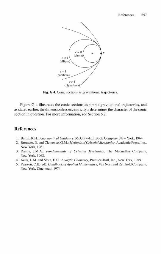
References 657
Pe = 0(circle)
e < 1(ellipse)
e = 1(parabola)
e > 1(Hyperbola)
Fig. G.4. Conic sections as gravitational trajectories.
Figure G-4 illustrates the conic sections as simple gravitational trajectories, andas stated earlier, the dimensionless eccentricity e determines the character of the conicsection in question. For more information, see Section 6.2.
References
1. Battin, R.H.: Astronautical Guidance, McGraw-Hill Book Company, New York, 1964.2. Brouwer, D. and Clemence, G.M.: Methods of Celestial Mechanics, Academic Press, Inc.,
New York, 1961.3. Danby, J.M.A.: Fundamentals of Celestial Mechanics, The Macmillan Company,
New York, 1962.4. Kells, L.M. and Stotz, H.C.: Analytic Geometry, Prentice-Hall, Inc., New York, 1949.5. Pearson, C.E. (ed): Handbook of Applied Mathematics, Van Nostrand Reinhold Company,
New York, Cincinnati, 1974.
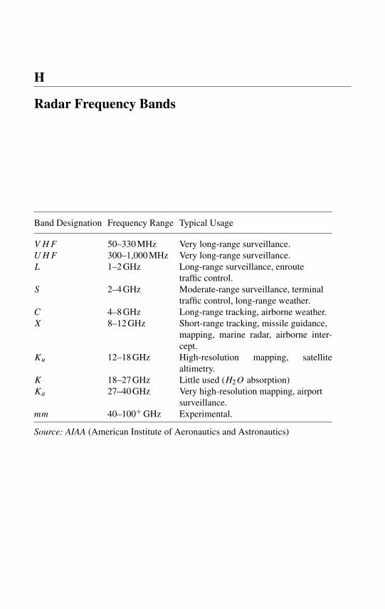
H
Radar Frequency Bands
Band Designation Frequency Range Typical Usage
VHF 50–330 MHz Very long-range surveillance.UHF 300–1,000 MHz Very long-range surveillance.L 1–2 GHz Long-range surveillance, enroute
traffic control.S 2–4 GHz Moderate-range surveillance, terminal
traffic control, long-range weather.C 4–8 GHz Long-range tracking, airborne weather.X 8–12 GHz Short-range tracking, missile guidance,
mapping, marine radar, airborne inter-cept.
Ku 12–18 GHz High-resolution mapping, satellitealtimetry.
K 18–27 GHz Little used (H2O absorption)Ka 27–40 GHz Very high-resolution mapping, airport
surveillance.mm 40–100+ GHz Experimental.
Source: AIAA (American Institute of Aeronautics and Astronautics)
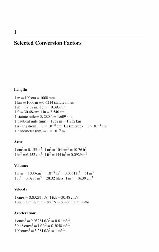
I
Selected Conversion Factors
Length:
1 m = 100 cm = 1000 mm1 km = 1000 m = 0.6214 statute miles1 m = 39.37 in; 1 cm = 0.3937 in1 ft = 30.48 cm; 1 in = 2.540 cm1 statute mile = 5, 280 ft = 1.609 km1 nautical mile (nm) = 1852 m = 1.852 km1Å (angstrom) = 1 × 10⁻⁸ cm; 1µ (micron) = 1 × 10⁻⁴ cm1 nanometer (nm) = 1 × 10⁻⁹ m
Area:
1 cm2 = 0.155 in2; 1 m2 = 104 cm2 = 10.76 ft2
1 in2 = 6.452 cm2; 1 ft2 = 144 in2 = 0.0929 m2
Volume:
1 liter = 1000 cm3 = 10−3 m3 = 0.0351 ft3 = 61 in3
1 ft3 = 0.0283 m3 = 28.32 liters; 1 in3 = 16.39 cm3
Velocity:
1 cm/s = 0.03281 ft/s; 1 ft/s = 30.48 cm/s1 statute mile/min = 88 ft/s = 60 statute miles/hr
Acceleration:
1 cm/s2 = 0.03281 ft/s2 = 0.01 m/s2
30.48 cm/s2 = 1 ft/s2 = 0.3048 m/s2
100 cm/s2 = 3.281 ft/s2 = 1 m/s2
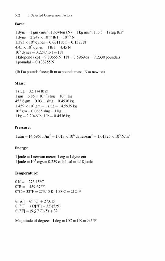
662 I Selected Conversion Factors
Force:
1 dyne = 1 gm cm/s2; 1 newton (N) = 1 kg m/s2; 1 lb f = 1 slug ft/s2
1 dyne = 2.247 × 10⁻⁶ lb f = 10−5 N1.383 × 104 dynes = 0.0311 lb f = 0.1383 N4.45 × 105 dynes = 1 lb f = 4.45 N105 dynes = 0.2247 lb f = 1 N1 kilopond (kp) = 9.80665 N; 1 N = 3.5969 oz = 7.2330 poundals1 poundal = 0.138255 N
(lb f = pounds force; lb m = pounds mass; N = newton)
Mass:
1 slug = 32.174 lb m1 gm = 6.85 × 10⁻⁵ slug = 10−3 kg453.6 gm = 0.0311 slug = 0.4536 kg1.459 × 104 gm = 1 slug = 14.5939 kg103 gm = 0.0685 slug = 1 kg1 kg = 2.2046 lb; 1 lb = 0.4536 kg
Pressure:
1 atm = 14.696 lbf/in2 = 1.013 × 10⁶ dynes/cm2 = 1.01325 × 10⁵ N/m2
Energy:
1 joule = 1 newton meter; 1 erg = 1 dyne cm1 joule = 107 ergs = 0.239 cal; 1 cal = 4.18 joule
Temperature:
0 K = −273.15◦C0◦R = −459.67◦F0◦C = 32◦F = 273.15 K; 100◦C = 212◦F
![K] =![◦C] + 273.15![◦C] = (Q[◦F] − 32)(5/9)![◦F] = (9Q[◦C]/5)+ 32
Magnitude of degrees: 1 deg = 1◦C = 1 K = 9/5◦F.
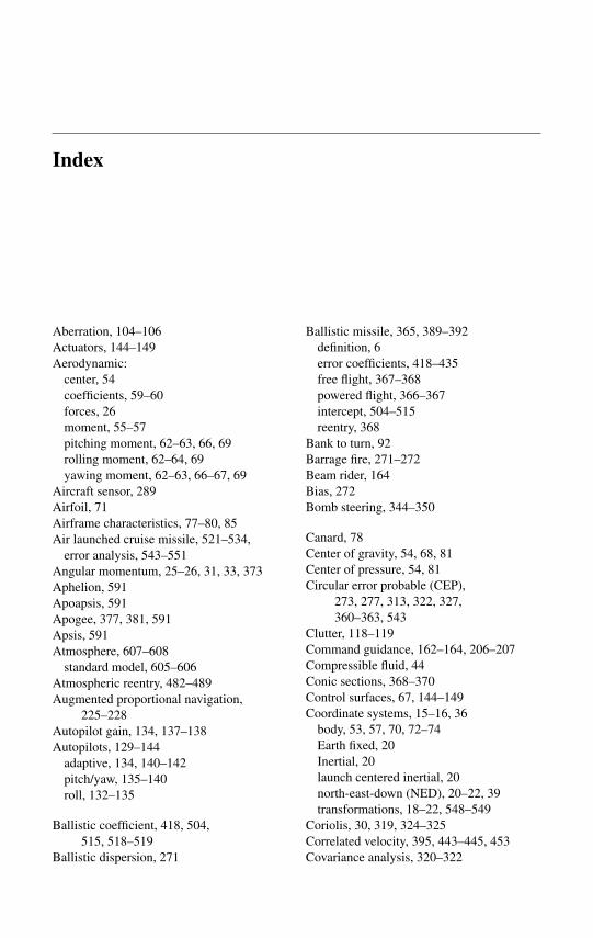
Index
Aberration, 104–106Actuators, 144–149Aerodynamic:
center, 54coefficients, 59–60forces, 26moment, 55–57pitching moment, 62–63, 66, 69rolling moment, 62–64, 69yawing moment, 62–63, 66–67, 69
Aircraft sensor, 289Airfoil, 71Airframe characteristics, 77–80, 85Air launched cruise missile, 521–534,
error analysis, 543–551Angular momentum, 25–26, 31, 33, 373Aphelion, 591Apoapsis, 591Apogee, 377, 381, 591Apsis, 591Atmosphere, 607–608
standard model, 605–606Atmospheric reentry, 482–489Augmented proportional navigation,
225–228Autopilot gain, 134, 137–138Autopilots, 129–144
adaptive, 134, 140–142pitch/yaw, 135–140roll, 132–135
Ballistic coefficient, 418, 504,515, 518–519
Ballistic dispersion, 271
Ballistic missile, 365, 389–392definition, 6error coefficients, 418–435free flight, 367–368powered flight, 366–367intercept, 504–515reentry, 368
Bank to turn, 92Barrage fire, 271–272Beam rider, 164Bias, 272Bomb steering, 344–350
Canard, 78Center of gravity, 54, 68, 81Center of pressure, 54, 81Circular error probable (CEP),
273, 277, 313, 322, 327,360–363, 543
Clutter, 118–119Command guidance, 162–164, 206–207Compressible fluid, 44Conic sections, 368–370Control surfaces, 67, 144–149Coordinate systems, 15–16, 36
body, 53, 57, 70, 72–74Earth fixed, 20Inertial, 20launch centered inertial, 20north-east-down (NED), 20–22, 39transformations, 18–22, 548–549
Coriolis, 30, 319, 324–325Correlated velocity, 395, 443–445, 453Covariance analysis, 320–322

664 Index
Cruise missiles, 521–527navigation system, 534–543system description, 527–532
Daisy cutter, 249D’Alembert’s principle, 45–46Delivery accuracy, 273–274Delta guidance, 470–471Direction cosine matrix (DCM), 18–19,
40, 43Drag coefficient, 55Drag polar, 59Dynamic pressure, 40, 54
Earth curvature, 351–353Earth oblateness effects,
399–403, 503, 516Earth rotation effects, 440–443Eccentric anomaly, 385–386, 579Eccentricity, 368–370, 654Electronic countermeasures (ECM), 122End game, 256–257English bias, 136, 151–153, 181, 205Epoch, 379Error analysis, 326–327, 543–547Error ellipse, 537Error sensitivity, 294–297Euler:
angles, 18–19, 34equations, 33
Euler-Lagrange equations, 49Explicit guidance, 466–469
Fire control computer (FCC), 292–293Forces, 26
axial, 71, 83normal, 65–66, 84side, 55–56, 60
Free flight, 367–368Free stream velocity, 68
Glint, 114–116Glitter point, 258–260Global Hawk, 619–620Global positioning system (GPS), 168,
576–583Global positioning system/inertial
navigation integration, 168, 583–586Gravitation models, 400, 503
Gravity, 342–343drop, 275turn, 460, 462–463, 466, 494–498
Great circle, 549, 592Guidance, 85, 173
active, 155beam rider, 164collision course interception, 165–166,
187–188command, 162–164, 206–207delta, 470–471deviated pursuit, 165explicit, 466–469homing, 158hyperbolic, 166implicit, 469–470laws, 162passive, 155, 160semi-active, 155, 159three point, 166
Guided missile definition, 5Gyrocompassing, 9
Hamilton’s principle, 49Hit equation, 392–395, 397Holonomic system, 46Homing-on-jam, 122–124Hour circle, 592
Imaging infrared (IIR), 111Implicit guidance
(see also guidance), 8–9Incompressible fluid, 44Inertial frame, 20In-plane error coefficients, 421–430Infrared seeker, 111–112, 125–129Infrared tracking, 125–129Irdome, 110, 125–129
Jamming, 122–124Jerk model, 232–233
Kalman filter, 236–237,517–518, 575–576
continuous, 237–240discrete, 240–242suboptimal, 242
Keplerian motion, 371, 373ellipse, 370
Index 665
Kepler’s first law, 378–379third law, 379
Kinetic energy, 48, 387, 409
Lagrange’s equations, 46–49, 324LAIRCM, 129Lambert’s theorem, 382–388Laser systems, 167, 298Lift, 55–57, 60
coefficient, 41, 55–57, 60Linear quadratic regulator, 235,
242–245, 330Load factor, 92, 94–95
Mach number, 23, 325Mass 23, 36MATLAB, 36Matrix Riccati equation, 238–245Maximum principle, 330Mean anomaly, 387
motion, 386Minimum:
energy, 247energy trajectory, 397, 403, 407–409,
415, 429fuel, 247principle, 330time, 246
Miss distance, 100–101, 105, 308–309Missile:
classification, 611–615control system, 457–461guidance equations,
174–175, 181–194launch envelope, 275, 353–354mathematical model, 91–95seeker, 102–104
Moments, 62inertia, 32pitching, 62–63rolling, 62–64, 69yawing, 62–63, 66–67, 69
Multipath, 118–119
Navier-Stokes equation, 44–45Navigation, 290, 471–472, 534–539
inertial, 8–9, 532, 543–551Newton’s equations, 22, 47, 49
second law, 25, 29
Noise, 113glint, 114–116range-independent, 115scintillation, 115–117thermal, 118–119white, 117, 237–238
Oblateness effects of the Earth, 399–400Orbital period, 378Out-of-plane error coefficients, 430–435
Parasitic attitude loop, 79, 101–102, 105,142–143
Particle beam, 262Perigee, 377, 381, 593Pitching moment, 62–63, 66, 69Powered flight, 366–367Predator, 618–619Probability of kill, 171, 263–265Proportional navigation, 161, 166,
194–218, 236augmented, 225–228biased, 195–196, 213effective ratio, 194, 202–204generalized, 196ideal, 196ratio, 194three-dimensional, 228–235true, 196
Q-guidance, 445–446, 451–452, 471-matrix, 445–450
Quaternions, 19, 40, 42–43
Radar, 110–113, 297–298cross-section, 116, 121frequency bands, 659
Radial error probable (REP), 277Radome, 104–107, 110–111
slope error, 106–108Ramjet, 88, 150Reentry, 368Refraction, 104–106Relative wind, 54–55Reynold’s number, 53, 63, 325Rigid body, 22–23Rolling moment, 62–64, 69Runge-Kutta method, 117, 178–179,
498–500
666 Index
Scintillation noise (see “noise”)Scramjet, 88, 150Seekers, 102–104
infrared, 111–112, 125–129radar, 111–113
Semi-latus rectum, 369Sidereal day, 593Sidereal hour angle, 593Sideslip angle, 44, 61–63Signal-to-noise ratio (SNR), 113–114, 122Skid-to-turn, 53, 56, 91Situational awareness/Situation assessment
(SA/SA), 333–336Speedgate, 151Spherical hit equation (see “Hit equation”)Standard atmosphere (see “atmosphere”)
Target offset, 279Targeting systems, 336–338Tensors, 17–18Terrain aided navigation (TAN), 574–575Terrain contour matching (TERCOM),
551–555position updates, 571–574roughness characteristics, 568–570system errors, 570–571
Terrain profile matching (TERPROM), 554True anomaly, 369, 378Two-body problem, 366–382
Unmanned aerial vehicle (UAV), 618–620Unmanned combat aerial vehicle(UCAV),
620–623Unpowered precision guided munitions,
644–646
V-1, V-2 rockets, 2–5Vectors, 15
transformation properties, 15–17Velocity-to-be-gained, 443–447, 449–454Velocity:
angular, 26–27required, 395, 411–413, 416
Virtual work, 45Vis viva equation, 388
Warheads, 85, 262–263Weapon delivery, 269–284White noise, 117, 237–238Wind axes, 57–59
Z-velocity steering, 459–460