maker projects you want to build!
TRANSCRIPT

MAKER PROJECTS YOU WANT TO BUILD!
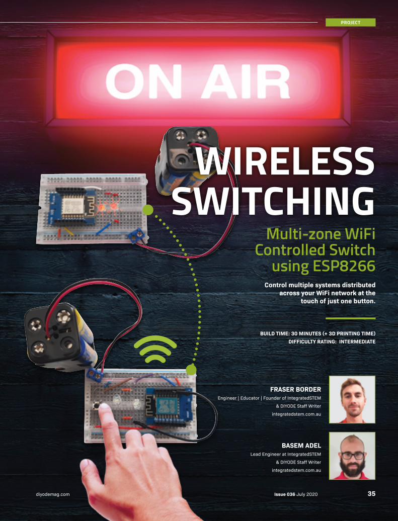
CREATE A MULTI-ZONE WIFI-CONTROLLED SWITCHOne button for distributed WiFi enabled control systems.
BUILD YOUR OWN 12V LITHIUM-POWERED UPSKeeps your 12V hardware running with lightweight battery power.
LEARN HOW TRANSFER AND ETCH YOUR OWN PCBThis tried and tested method for creating PCBs is very handy!
IT'S BIGGER... IT'S BETTER...
OCTOLED3PROGRAMMABLE 8x8x8 LED CUBE
Issue 036 July 2020 AUS: $9.95 inc. GST
ISSN: 2207-8045
9 772207
804002
36


74
LOVE YOUR PRINT MAGAZINES? Premium Digital Membership is included with every print subscription and single-issue purchase. To access 30 days of free membership and the PDF magazine download for this issue, enter the code in this block from your printed edition.
53
60
08
68
Issue 036 July 2020 diyodemag.com4

■ SIMON SAYS Handheld Electronic Game Using Arduino
■ THE CLASSROOM The ATmega328P IC
■ PCBEASY How To Etch A PCB: Part 1
■ WHAT THE TECH Finger On The Pulse: Build Your Own Heartbeat Sensor
■ KEYLESS ENTRY RFID Access Control with Attendance Recording
■ WIRELESS SWITCHING Multi-zone WiFi Controlled Switch Using ESP8266
■ PERSISTANT POWER Arduino-Based High Capacity 12V UPS
■ OCTOLED3 Programmable 8x8x8 Blue LED Cube: Part 2
■ EDITOR'S LETTER DIYODE Turns THREE!
FEATURES:
EDUCATION:
PROJECTS:
53
08
68
91
16
35
60
74
06
35
16
WIN 1 OF 10
4 × 4 × 4 LED
CUBE KITS*
*Terms & conditions
apply. See page 7.
07
5Issue 036 July 2020diyodemag.com

Every time a DIYODE anniversary rolls around, we debate whether or not it should mark the first issue's release, the pre-launch in March 2017, a perfect division of 12 issues, or something else?
Well, just as it happens with many celebrations, we'll stick with July as an "in spirit" anniversary regardless of the maths, since that feels right. In that time, we've published 3624 pages (issue #003 was a bumper) with about two million words (ok - that's a wild guess, but the average issue has around 60,000 words, so the maths holds up).
Considering a PhD thesis is around 100,000 words, it does help create perspective on the volume of content we've produced in that time. What's perhaps more amazing, is that many of you own each and every issue!
Naturally, while I enjoy writing some content myself such as our Machine Learning series, I can't say enough about the amazing team working behind the scenes. There are so many moving parts that work together to make this possible.
From our Editor Murray who ensures projects from all sources are ready for publication even when someone's struggling with the code, to Danielle who traverses our warehouse filling the daily backissue orders and enquiries, and our creative team who translate it all into a great looking magazine. From our staff writers who have been with us from the start, or only just joined the team, your contribution and enthusiasm for what you do is an inspiration to me, and a powerful example of what makes Making so great.
At the time of writing this, we're running our promotion for bundles of back issues. It's hard to think that DIYODE is already old enough to actually do such a thing! However we have been absolutely delighted with the interest in these bundle packs. We've sent hundreds out the door across Australia, and indeed the world. It's not only great to get these back issues in front of makers, but we really hate counting magazines at the end of June too!
We also just hit a milestone on the official DIYODE Instagram, with over 20,000 of you joining us over there to keep the conversation going. Sure, it's not huge numbers if you're Elon Musk, but it's great to see this number increasing rapidly each day now that we're giving it the attention it deserves.
Lastly, and most importantly, to the many thousands (tens of thousands actually, but who's counting) who interact with DIYODE each and every month either with the printed magazine, our website, social media or however else you find us; we appreciate your interest in DIYODE and look forward to continued engagement.
Rob Bell
DIYODE Turns THREE!
EDITOR-IN-CHIEFRob Bell
EDITORMurray Roberts
TECHNICAL EDITORBob Harper
STAFF WRITERSOliver HigginsDaniel KochSophie ParkerJohann WyssAndy ClarkLiam DaviesDean CorvaFraser BorderBasem Adel Geoff Cohen
CREATIVE & DIGITAL TEAMLuke ParsonageKayla GourlayMelanie HeardDanielle BellJacqui CreasyDan Tully
CONTRIBUTORSMiles Hitchen
AN INDEPENDENT PUBLICATION.
Published by B.E. DIYODE Pty Ltd
ACN 616 556 622 ABN 50 616 556 622
Unit 9 / 10 Enterprise Close, West Gosford NSW 2250 Australia
© 2020 No part of this publication may be reproduced without written authorisation. All contributed content is owned by the authors and reproduced with permission. All product names, logos, and brands are property of their respective owners. Printed by Ovato.
Newsagent distribution within Australia managed exclusively by Gordon & Gotch.
ISSN: 2207-8045
Print subscriptions are available to Australian and NZ residents from AU$8.75 per issue including GST. See diyodemag.com for more international subscription pricing.
All prices quoted in AUD including GST unless noted otherwise. All prices are correct at time of printing and subject to change without notice.
ADVERTISE WITH [email protected]
CONTACT [email protected]+61 2 4326 0160
FOLLOW US @diyodemag
Issue 036 July 2020 diyodemag.com6

WIN 1 OF 10
Proudly provided by our friends at Jaycar
jaycar.com.auEntries must be received before Saturday 1 August 2020. Terms & Conditions apply. See website for details. Arduino Uno not included.
To enter, simply head to diyode.io/036comp & tell us why you want to win one.
4 × 4 × 4 LED CUBE KITS
VALUED AT $19 95CAT NO. KM1097
Being part of the maker family generally means at some point or another you’ve encountered an ATmega328P. This humble microcontroller is cheap, robust, and easy to program, the backbone of many maker projects.
Generally speaking, the main reason we’ve heard of the ATmega328P is from using an Arduino, a development board centred around the Mega series of microcontrollers, specifically the Uno and Nano, which use different packages of the ATmega328P.
THE ATMEGA328P IC
The ATmega328P is the brains of many Maker projects. We take a look at this versatile chip, different ways to program it, and how to use one standalone.
DEAN CORVADIYODE Staff Writer
Issue 036 July 2020 diyodemag.com8
THE CLASSROOM
We’ve used the ATmega328P in its bare form in previous articles, however, let’s spend time just focusing on the ATmega328P, as you may learn something different from the Mega series in its wild form, outside its usual Arduino habitat.
But why use the ATmega328P on its own and not just stick to the development board? Simply put, we can significantly reduce the size of our projects. Once we’ve uploaded our code to the microcontroller, all the additional connections and components on the development board may not be necessary, such as the USB connector, or female pin headers. Thus, we can implement the microcontroller only with its necessary components to a breadboard or custom designed printed circuit board.
THE ATMEGA328P
Briefly summarising, the ATmega328P is an 8-bit microcontroller that operates on a RISC architecture. 8-bit means the processor uses an 8-bit register, which can handle 2^8 or 256 data values, which seems low for today’s standards, however, the higher the bit count and processing speed, the more power consumption the processor uses, hence, why microcontrollers are a favourable choice for low-power solutions.
The ATmega328P has many peripheral and special features that can be found in its 294-page datasheet(!). We can’t possibly list them all, otherwise, our article will become a datasheet also. Instead, we will focus on some key aspects that you may not have known about the ATmega328P.
1234567891011121314
2827262524232221201918171615
PC5 (ADC5/SCL/PCINT13)PC4 (ADC4/SDA/PCINT12)PC3 (ADC3/PCINT11)PC2 (ADC2/PCINT10)PC1 (ADC1/PCINT9)PC0 (ADC0/PCINT8)GNDAREFAVCCPB5 (SCK/PCINT5)PB4 (MISO/PCINT4)PB3 (MOSI/OC2A/PCINT3)PB2 (SS/OC1B/PCINT2)PB1 (OC1A/PCINT1)
(PCINT14/RESET) PC6(PCINT16/RXD) PD0(PCINT17/TXD) PD1(PCINT18/TXD) PD2
(PCINT19/OC2B/INT1) PD3(PCINT20/XCK/T0) PD4
VCCGND
(PCINT6/XTAL1/TOSC1) PB6(PCINT7/XTAL2/TOSC2) PB7
(PCINT21/OC0B/T1) PD5(PCINT22/OC0A/AIN0) PD6
(PCINT23/AIN1) PD7(PCINT0/CLKO/ICP1) PB0
ATm
ega3
28P
It is also the IC used on the Arduino Uno board. This PDIP package is really good for prototyping due to its breadboard compatibility. If the final solution of your project needs to be compact, the ATmega328P-MM is a 4 x 4mm surface-mount package to optimise your PCB space, however, these can be near impossible to solder by hand.
It is also the IC used on the Arduino Uno board. This PDIP package is really good for prototyping, due to its breadboard compatibility, but if the final solution of your project need to be compact, the ATmega328P-MM is a 4 x 4mm surface-mount package, optimising PCB space for other components.
APPLICATION AND PROGRAMMING METHODS
There are many methods to program your ATmega328P, and different ways to use an ATmega328P in a circuit depending on your application.
Over the following pages, we will describe four different projects that you can easily build and test for yourself.
We will explore four different programming methods so you can choose the best programmer for your projects. This includes using an Arduino Uno, an FTDI breakout board, and an In-Circuit Serial Programmer (ICSP).
We will also cover when to use the ATmega328P's internal oscillator or when you need to apply an external crystal oscillator.
LET'S GET HANDS-ON
To get started, you will need to get the parts that are common to all four builds, and the additional parts for the build you intend to make. ››
PARTS REQUIRED FOR ALL FOUR PROJECTS: JAYCAR ALTRONICS CORE ELECTRONICS1 x 16MHz Crystal (Not required for Build 4) RQ5296 V1289A COM-00536
2 x 22pF Capacitors* (Not required for Build 4) RC5316 R2814 CE05189
1 x LED* ZD0150 Z0800 CE05104
1 x 330Ω Resistor* RR2762 R0040 PRT-14490
* Quantity shown, may be sold in packs. You’ll also need a breadboard and prototyping hardware.
ZZ8727 ATMEGA328P MCU IC with Arduino Uno Bootloader MAGE CREDIT: jaycar.com.au
9Issue 036 July 2020diyodemag.com
THE CLASSROOM
››For this example, we will transfer the ATmega328P IC on your Arduino Uno onto a breadboard to work stand-alone (We just use the Uno for power). First, let’s load the simple blink program onto the Uno.
With your Arduino Uno connected to your computer via USB, go to Tools › Board and ensure Arduino / Genuino Uno is selected.
Go to Tools › Port and select the port your Uno is plugged into, then select File › Examples › 01.Basics › Blink and upload to the Arduino Uno. We should now see the built-in LED on the Arduino Uno blinking every second.
Disconnect your Arduino Uno from USB so that it is powered off. Then, very carefully remove the ATmega328P from the Arduino Uno, and place it into a breadboard.
If you do not have access to an IC removal tool, an easy way to carefully remove the ATmega328P from the Arduino socket is by using a very thin flat-head screwdriver, and gently pry both ends back and forth until its removed, ensuring no pins are bent.
To operate this ATmega328P, we need a source of power. We also need
a 16MHz external crystal oscillator and two 22pF ceramic capacitors. Microcontrollers use an oscillation signal to generate a clock signal, which determines the speed the microcontroller operates its processes. This means the microcontroller conducts an operation every time there is a state change in the clock signal. Arduino uses an external crystal oscillator for this, meaning it operates at a processing speed of 16MHz. The ATmega328P actually contains its own internal oscillators, however, they are inferior to the external crystal in terms of stability. The capacitors used with the external crystal are there to resonate with the crystals inductance, meaning the crystal will resonate on its fundamental frequency.
To operate the blink program, we need an LED and 330Ω resistor, which will limit the current to the LED to avoid it burning out, and prevent too much current draw from the ATmega328P, as the maximum current draw per pin is 40mA.
Follow the schematic and Fritzing to wire your circuit. Use the Arduino as the source of power, as it contains a 5V regulated output. You will need to connect it to an available USB port on your computer or USB power source, or use a DC power supply. You should now see the LED blinking on your breadboard. Success!
Build 1:
Using an Arduino Uno Board
+5V
330D
19
7 20
PB1/PWMPB0AREF
PB2/PWMPB3/MOSI/PWM
PB4/MISOPB5/SCK
PC1/ADC1PC0/ADC0
PC2/ADC2PC3/ADC3
PC4/ADC4/SDAPC5/ADC5/SCL
PD0/RXPD1/TX
PD2/INT0PD3/INT1/PWM
PD4/XCK/TOPD5/PWMPD6/PWM
PD7
RESET/PC6
9XTAL1/PB610XTAL2/PB7
VCC
AVCC
22pF
22pF
8
GND
GND
GND
IC1ATmega328P
16MHz
16MHz
22
pF 2
p
ATmega328P
ADDITIONAL PARTS FOR BUILD 1: JAYCAR ALTRONICS CORE ELECTRONICS1 x Arduino Uno or Compatible XC4410 Z6280 A000066
1 x USB A-B Lead WC7906 P1911C FIT0056
Issue 036 July 2020 diyodemag.com10
THE CLASSROOM
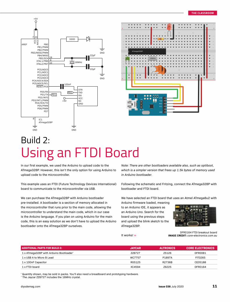
In our first example, we used the Arduino to upload code to the ATmega328P. However, this isn’t the only option for using Arduino to upload code to the microcontroller.
This example uses an FTDI (Future Technology Devices International) board to communicate to the microcontroller via USB.
We can purchase the ATmega328P with Arduino bootloader pre-installed. A bootloader is a section of memory allocated in the microcontroller that runs prior to the main code, allowing the microcontroller to understand the main code, which in our case is the Arduino language. If you plan on using Arduino for the main code, this is an easy solution as we don’t have to upload the Arduino bootloader onto the ATmega328P ourselves.
Note: There are other bootloaders available also, such as optiboot, which is a simpler version that frees up 1.5k bytes of memory used in Arduino bootloader.
Following the schematic and Fritzing, connect the ATmega328P with bootloader and FTDI board.
We have selected an FTDI board that uses an Atmel ATmega8u2 with Arduino firmware loaded, meaning to an Arduino IDE, it appears as an Arduino Uno. Search for the board using the previous steps and upload the blink sketch to the ATmega328P.
It works! ››
Build 2:
Using an FTDI Board
+5V
19
7 20
PB1/PWMPB0AREF
PB2/PWMPB3/MOSI/PWM
PB4/MISOPB5/SCK
PC1/ADC1PC0/ADC0
PC2/ADC2PC3/ADC3
PC4/ADC4/SDAPC5/ADC5/SCL
PD0/RXPD1/TX
PD2/INT0PD3/INT1/PWM
PD4/XCK/TOPD5/PWM
DTRTXDRXIVCCNCGND
PD1
PD6/PWMPD7
RESET/PC6
9XTAL1/PB610XTAL2/PB7
VCC
AVCC
22pF
22pF
100nF
8
GND GND
+5V
GND
GND
IC1ATmega328P
16MHz
PD1
330D
5V
3.3V
DTR
TXD
RXI
VCC
GND
2p
F
16MHz
22
pF 2
p
ATmega328P
0.1
ADDITIONAL PARTS FOR BUILD 2: JAYCAR ALTRONICS CORE ELECTRONICS1 x ATmega328P with Arduino Bootloader^ ZZ8727 Z5126 DFR0081
1 x USB A to Micro B Lead WC7757 P1897A FIT0265
1 x 100nF Capacitor RG5125 R2736B CE05188
1 x FTDI board XC4594 Z6225 DFR0164
DFR0164 FTDI breakout boardIMAGE CREDIT: core-electronics.com.au
* Quantity shown, may be sold in packs. You’ll also need a breadboard and prototyping hardware. ^ The Jaycar ZZ8727 includes the 16MHz crystal.
11Issue 036 July 2020diyodemag.com
THE CLASSROOM
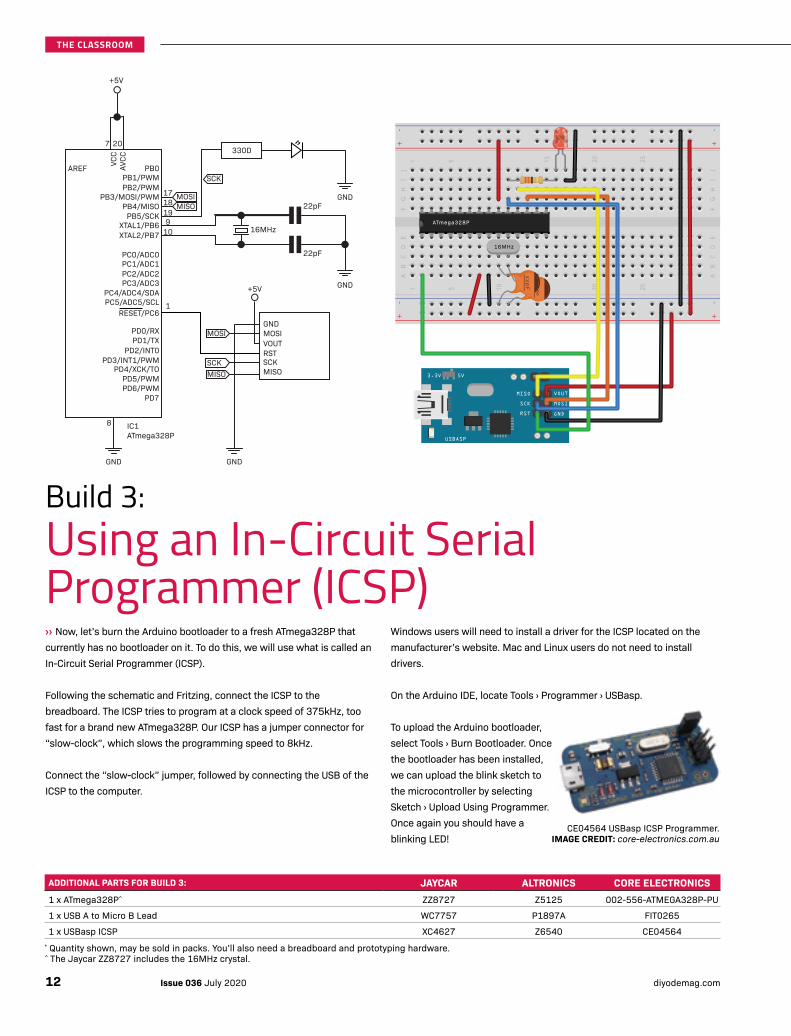
››Now, let’s burn the Arduino bootloader to a fresh ATmega328P that currently has no bootloader on it. To do this, we will use what is called an In-Circuit Serial Programmer (ICSP).
Following the schematic and Fritzing, connect the ICSP to the breadboard. The ICSP tries to program at a clock speed of 375kHz, too fast for a brand new ATmega328P. Our ICSP has a jumper connector for “slow-clock”, which slows the programming speed to 8kHz.
Connect the “slow-clock” jumper, followed by connecting the USB of the ICSP to the computer.
Windows users will need to install a driver for the ICSP located on the manufacturer’s website. Mac and Linux users do not need to install drivers.
On the Arduino IDE, locate Tools › Programmer › USBasp.
To upload the Arduino bootloader, select Tools › Burn Bootloader. Once the bootloader has been installed, we can upload the blink sketch to the microcontroller by selecting Sketch › Upload Using Programmer. Once again you should have a blinking LED!
Build 3:
Using an In-Circuit Serial Programmer (ICSP)
+5V
191817
7 20
PB1/PWMPB0AREF
PB2/PWMPB3/MOSI/PWM
PB4/MISOPB5/SCK
PC1/ADC1PC0/ADC0
PC2/ADC2PC3/ADC3
PC4/ADC4/SDAPC5/ADC5/SCL
PD0/RXPD1/TX
PD2/INT0PD3/INT1/PWM
PD4/XCK/TOPD5/PWM
GNDMOSIVOUTRSTSCKMISO
PD6/PWMPD7
RESET/PC6
9XTAL1/PB610XTAL2/PB7
VCC
AVCC
22pF
22pF
8
GND GND
+5V GND
GND
IC1ATmega328P
16MHz
SCK
SCK
330D
1
MOSIMISO
MOSI
MISO 5V3.3V
VOUTMISO
SCK
RST GND
MOSI
USBASP
2p
F16MHz
22
pF 2
p
ATmega328P
ADDITIONAL PARTS FOR BUILD 3: JAYCAR ALTRONICS CORE ELECTRONICS1 x ATmega328P^ ZZ8727 Z5125 002-556-ATMEGA328P-PU
1 x USB A to Micro B Lead WC7757 P1897A FIT0265
1 x USBasp ICSP XC4627 Z6540 CE04564* Quantity shown, may be sold in packs. You’ll also need a breadboard and prototyping hardware. ^ The Jaycar ZZ8727 includes the 16MHz crystal.
CE04564 USBasp ICSP Programmer.IMAGE CREDIT: core-electronics.com.au
Issue 036 July 2020 diyodemag.com12
THE CLASSROOM

Let’s move away from Arduino now and use the ATmega328P in its bare form, and program using compilers other than Arduino, such as C++ and C.
The manufacturer of the ATmega328P, Atmel, offer programming of the microcontroller using their software, Atmel Studio. This software is free to download, with the latest revision being Atmel Studio 7, however, it only operates on Windows and is a large program, intended for the professional market.
Using this software, we can use the full potential of the ATmega328P. This includes operating a clock speed from as low as 1MHz up to a maximum of 20MHz and an operating voltage from as low as 1.8 volts up to 5.5 volts. We can select the internal crystal using Atmel Studio, AVRfuses, and other options. ››
Build 4:
ATmega328P Programmed Using C
+3.3V
191817
7 20
PB1/PWMPB0AREF
PB2/PWMPB3/MOSI/PWM
PB4/MISOPB5/SCK
PC1/ADC1PC0/ADC0
PC2/ADC2PC3/ADC3
PC4/ADC4/SDAPC5/ADC5/SCL
PD0/RXPD1/TX
PD2/INT0PD3/INT1/PWM
PD4/XCK/TOPD5/PWM
GNDMOSIVOUTRSTSCKMISO
PD6/PWMPD7
RESET/PC6
XTAL1/PB6XTAL2/PB7
VCC
AVCC
8
GND GND
IC1ATmega328P
SCK
SCK
MOSIMISO
MOSI
MISO
330Ω
+3.3V
VOUTMISO
SCKRST GND
MOSI
ATmega328P
3.3V
ADDITIONAL PARTS FOR BUILD 4: JAYCAR ALTRONICS CORE ELECTRONICS1 x ATmega328P ZZ8727 Z5125 002-556-ATMEGA328P-PU
1 x USB A to Micro B Lead WC7757 P1897A FIT0265
1 x ICSP (eg. Atmel-ICE or similar. See text.) Element 14: 2407172
* Quantity shown, may be sold in packs. You’ll also need a breadboard and prototyping hardware. ^ The Jaycar ZZ8727 includes the 16MHz crystal.
2407172 ATMEL-ICE Basic Debugger. IMAGE CREDIT: element14.com
13Issue 036 July 2020diyodemag.com
THE CLASSROOM
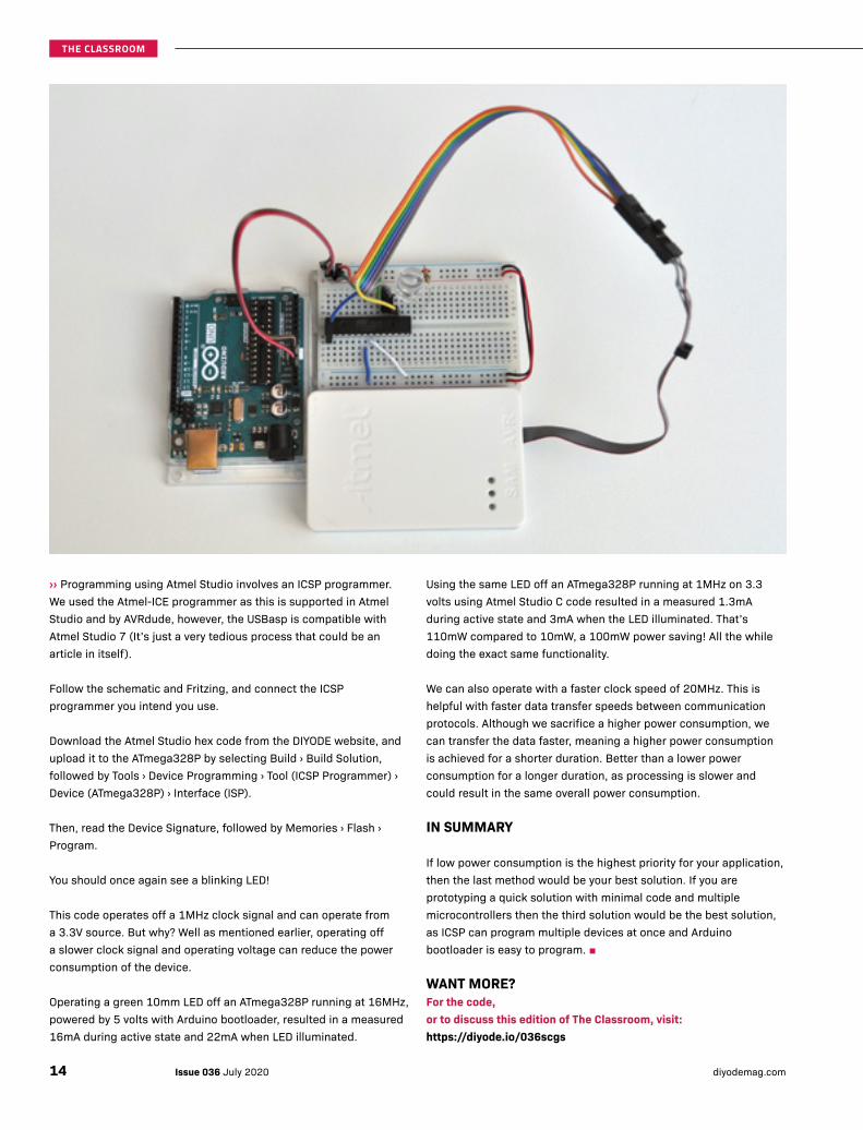
››Programming using Atmel Studio involves an ICSP programmer. We used the Atmel-ICE programmer as this is supported in Atmel Studio and by AVRdude, however, the USBasp is compatible with Atmel Studio 7 (It’s just a very tedious process that could be an article in itself).
Follow the schematic and Fritzing, and connect the ICSP programmer you intend you use.
Download the Atmel Studio hex code from the DIYODE website, and upload it to the ATmega328P by selecting Build › Build Solution, followed by Tools › Device Programming › Tool (ICSP Programmer) › Device (ATmega328P) › Interface (ISP).
Then, read the Device Signature, followed by Memories › Flash › Program.
You should once again see a blinking LED!
This code operates off a 1MHz clock signal and can operate from a 3.3V source. But why? Well as mentioned earlier, operating off a slower clock signal and operating voltage can reduce the power consumption of the device.
Operating a green 10mm LED off an ATmega328P running at 16MHz, powered by 5 volts with Arduino bootloader, resulted in a measured 16mA during active state and 22mA when LED illuminated.
Using the same LED off an ATmega328P running at 1MHz on 3.3 volts using Atmel Studio C code resulted in a measured 1.3mA during active state and 3mA when the LED illuminated. That’s 110mW compared to 10mW, a 100mW power saving! All the while doing the exact same functionality.
We can also operate with a faster clock speed of 20MHz. This is helpful with faster data transfer speeds between communication protocols. Although we sacrifice a higher power consumption, we can transfer the data faster, meaning a higher power consumption is achieved for a shorter duration. Better than a lower power consumption for a longer duration, as processing is slower and could result in the same overall power consumption.
IN SUMMARY
If low power consumption is the highest priority for your application, then the last method would be your best solution. If you are prototyping a quick solution with minimal code and multiple microcontrollers then the third solution would be the best solution, as ICSP can program multiple devices at once and Arduino bootloader is easy to program. ■
WANT MORE?For the code, or to discuss this edition of The Classroom, visit: https://diyode.io/036scgs
Issue 036 July 2020 diyodemag.com14
THE CLASSROOM


KEYLESS ENTRY RFID Access Control with Attendance Recording
Issue 036 July 2020 diyodemag.com16
PROJECT
Grant access to multiple users to a room or system using RFID technology, and record the date and time on when they enter.
JOHANN WYSSDIYODE Staff Technical Writer
BUILD TIME: 3 HOURS (+ 3D PRINTING TIME) DIFFICULTY RATING: INTERMEDIATE
We see RFID (Radio Frequency Identification) technology used in many parts of our life these days, from ticketing systems on public transport to gaining entry to our workplaces. Gymnasiums, for example, use the technology to grant access to members at any time of day or night, and record the member’s attendance without any staff at the gym at the time. RFID tags are in our passports, the DVDs we rent from the local kiosk, in the books we borrow from the library, and much more. Consider also the tag stuck to your car’s windscreen that beeps when you pass under a toll point.
Using RFID technology for gaining access to a room or building means there’s no need for physical keys that can be lost, stolen and copied, which could mean replacing your locks in some circumstances. It also means you know specifically who is entering based on their unique RFID number, and with the right systems in place, you can record the date and time of them entering.
This brings us to our project, which makers can build using commonly available RFID tags and readers.
THE BROAD OVERVIEW
For this project, we are building an RFID ingress control system that will give you the ability to control an electronic door lock and record the time and details of the person who used it.
The project uses an RFID reader module, various RFID tags, key-fobs and wafer cards, an RTC (Real Time Clock) module for timing purposes, and an SD Card Module to store the data. All managed by an Arduino Uno microcontroller, with information displayed on an LCD screen.
In our application, we will trigger an electronic door lock, however, you could just use the system for attendance purposes or to trigger other devices.
HOW IT WORKS
RFID TECHNOLOGY
RFID technology is an exciting field that was developed in the 1980s as a replacement for the humble barcode. The benefits of the technology are that you don’t need a line-of-sight to read the information as a barcode does. This means your products zipping down a production line don’t all need to be sorted in a way that the barcode is in a position ready to be scanned. This technology became a revolution in the manufacturing industry and is now widely being used across many industries.
Other RFID applications include:
• Small RFID chip implanted in pets to help identify the owner if it escapes.
• Passport and driver's license to provide rapid data verification as well as making it very difficult to make fraudulent copies.
• Retail stores use the technology as a means of detecting and preventing theft of their merchandise.
• Video game add-ons, such as Skylanders™ to identify which character you’re playing with.
Whilst we use RFID in our everyday lives, for the most part, most of us know very little about how it works.
There are two types of RFID tags:
• Passive, powered via the RFID reader.
• Active, with the RFID chip powered by a small battery.
Both technologies are essentially the same, however, the active with its battery gives the chip significantly more range. Passive RFID cards, like the ones we are using for this project, have a maximum transit / receive distance of about 10 metres, whereas the RFID chip in your car’s toll reader has a maximum read distance of up to 100 metres.
With that said, the maximum transmit distance relies on various factors including the transmit power. For this project, we found that the combination of this reader and the supplied RFID cards the maximum transmit / receive distance was about 50mm.
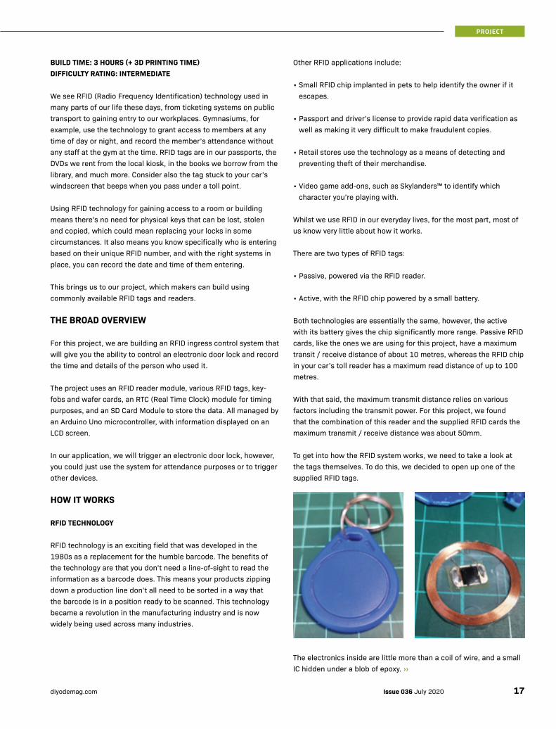
To get into how the RFID system works, we need to take a look at the tags themselves. To do this, we decided to open up one of the supplied RFID tags.
The electronics inside are little more than a coil of wire, and a small IC hidden under a blob of epoxy. ››
17Issue 036 July 2020diyodemag.com
PROJECT
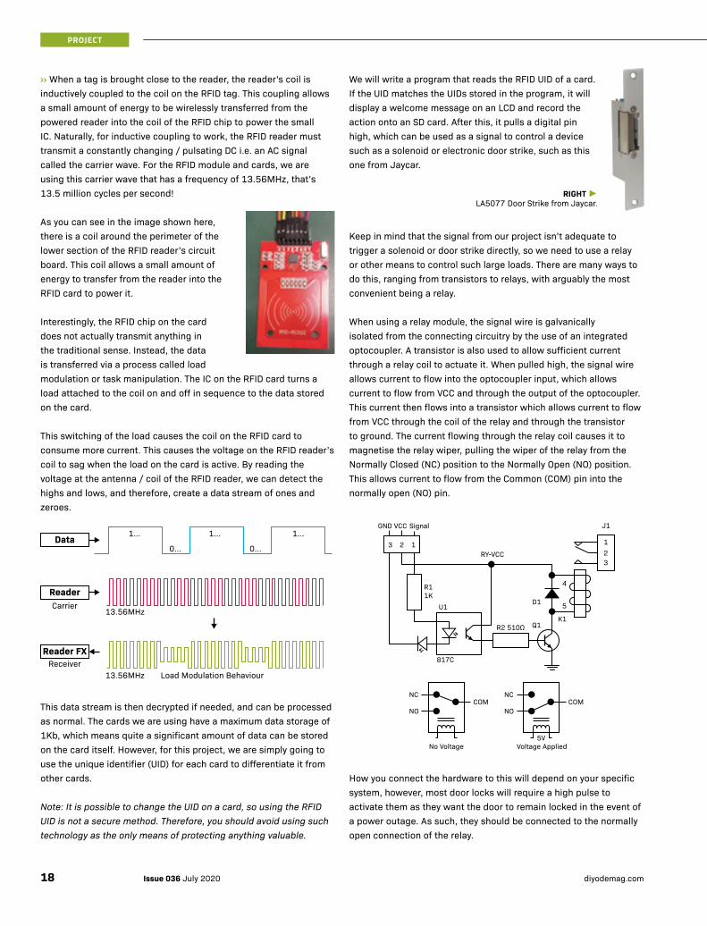
››When a tag is brought close to the reader, the reader's coil is inductively coupled to the coil on the RFID tag. This coupling allows a small amount of energy to be wirelessly transferred from the powered reader into the coil of the RFID chip to power the small IC. Naturally, for inductive coupling to work, the RFID reader must transmit a constantly changing / pulsating DC i.e. an AC signal called the carrier wave. For the RFID module and cards, we are using this carrier wave that has a frequency of 13.56MHz, that’s 13.5 million cycles per second!
As you can see in the image shown here, there is a coil around the perimeter of the lower section of the RFID reader’s circuit board. This coil allows a small amount of energy to transfer from the reader into the RFID card to power it.
Interestingly, the RFID chip on the card does not actually transmit anything in the traditional sense. Instead, the data is transferred via a process called load modulation or task manipulation. The IC on the RFID card turns a load attached to the coil on and off in sequence to the data stored on the card.
This switching of the load causes the coil on the RFID card to consume more current. This causes the voltage on the RFID reader’s coil to sag when the load on the card is active. By reading the voltage at the antenna / coil of the RFID reader, we can detect the highs and lows, and therefore, create a data stream of ones and zeroes.
This data stream is then decrypted if needed, and can be processed as normal. The cards we are using have a maximum data storage of 1Kb, which means quite a significant amount of data can be stored on the card itself. However, for this project, we are simply going to use the unique identifier (UID) for each card to differentiate it from other cards.
Note: It is possible to change the UID on a card, so using the RFID UID is not a secure method. Therefore, you should avoid using such technology as the only means of protecting anything valuable.
1...
0...
1... 1...
0...Data
13.56MHz Load Modulation BehaviourReceiver
Reader FX
Carrier13.56MHz
Reader
We will write a program that reads the RFID UID of a card. If the UID matches the UIDs stored in the program, it will display a welcome message on an LCD and record the action onto an SD card. After this, it pulls a digital pin high, which can be used as a signal to control a device such as a solenoid or electronic door strike, such as this one from Jaycar.
RIGHT ►LA5077 Door Strike from Jaycar.
Keep in mind that the signal from our project isn’t adequate to trigger a solenoid or door strike directly, so we need to use a relay or other means to control such large loads. There are many ways to do this, ranging from transistors to relays, with arguably the most convenient being a relay.
When using a relay module, the signal wire is galvanically isolated from the connecting circuitry by the use of an integrated optocoupler. A transistor is also used to allow sufficient current through a relay coil to actuate it. When pulled high, the signal wire allows current to flow into the optocoupler input, which allows current to flow from VCC and through the output of the optocoupler. This current then flows into a transistor which allows current to flow from VCC through the coil of the relay and through the transistor to ground. The current flowing through the relay coil causes it to magnetise the relay wiper, pulling the wiper of the relay from the Normally Closed (NC) position to the Normally Open (NO) position. This allows current to flow from the Common (COM) pin into the normally open (NO) pin.
How you connect the hardware to this will depend on your specific system, however, most door locks will require a high pulse to activate them as they want the door to remain locked in the event of a power outage. As such, they should be connected to the normally open connection of the relay.
R11K
U1
817C
123
R2 510Ω Q1
D1 5
K1
4
RY-VCC
J1GND
3 2 1
VCC Signal
NC
NOCOM
No Voltage
NC
NOCOM
Voltage Applied5V
Issue 036 July 2020 diyodemag.com18
PROJECT
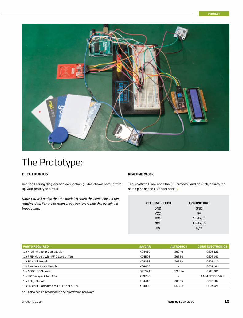
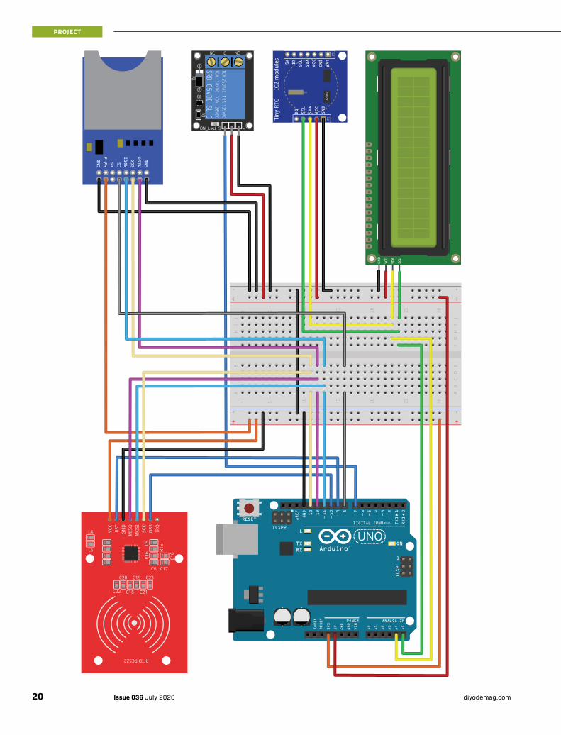
The Prototype:ELECTRONICS
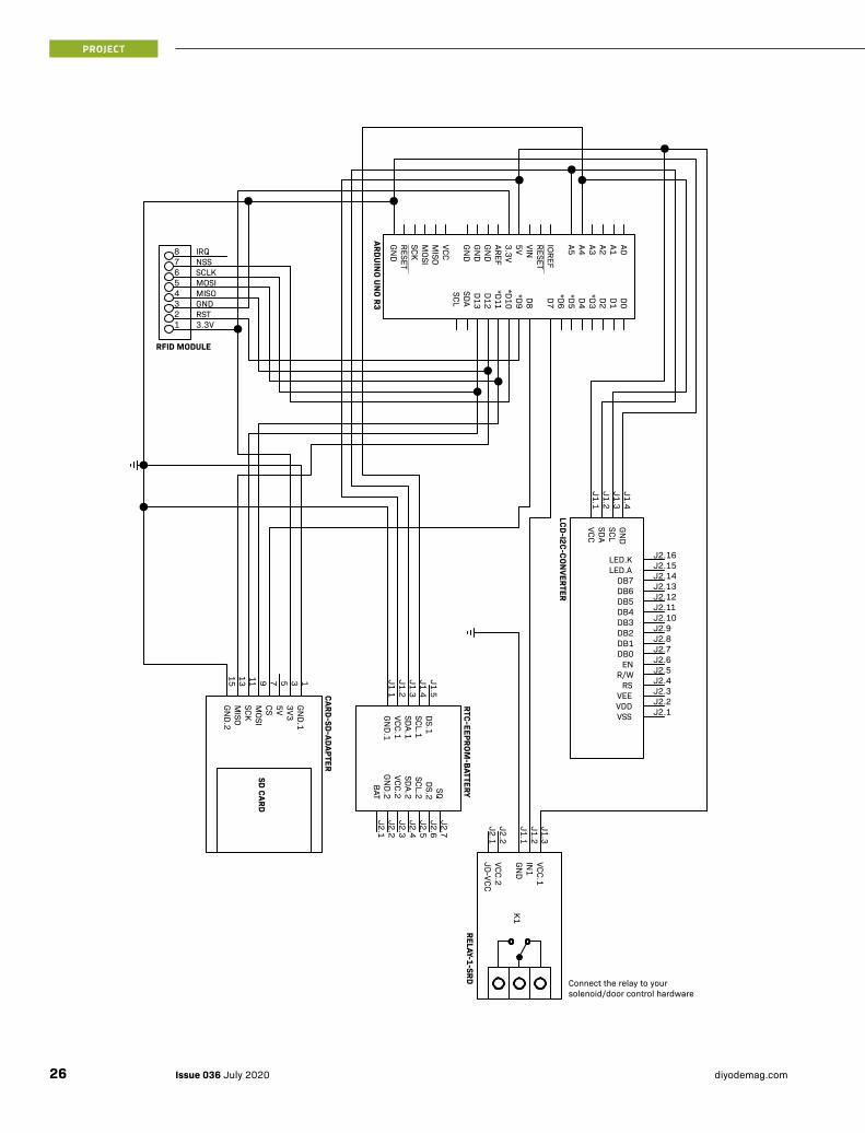
Use the Fritzing diagram and connection guides shown here to wire up your prototype circuit.
Note: You will notice that the modules share the same pins on the Arduino Uno. For the prototype, you can overcome this by using a breadboard.
REALTIME CLOCK
The Realtime Clock uses the I2C protocol, and as such, shares the same pins as the LCD backpack. ››
REALTIME CLOCK ARDUINO UNOGND GNDVCC 5VSDA Analog 4SCL Analog 5DS N/C
PARTS REQUIRED: JAYCAR ALTRONICS CORE ELECTRONICS1 x Arduino Uno or Compatible XC4410 Z6240 CE05629
1 x RFID Module with RFID Card or Tag XC4506 Z6356 CE07140
1 x SD Card Module XC4386 Z6353 CE05113
1 x Realtime Clock Module XC4450 - CE07141
1 x 1602 LCD Screen QP5521 Z7002A DRF0063
1 x I2C Backpack for LCDs XC3706 - 018-LCD1602-I2c
1 x Relay Module XC4419 Z6325 CE05137
1 x SD Card (Formatted to FAT16 or FAT32) XC4989 D0328 CE04628
You’ll also need a breadboard and prototyping hardware.
19Issue 036 July 2020diyodemag.com
PROJECT

››SD CARD MODULE
The SD card module uses the SPI communication protocol.
RC522 RFID MODULE
Like the SD card module, the RFID module also uses the SPI communication protocol.
Note: The RFID module’s VCC requires 3.3V. Powering it to 5V will damage the module. The data pins, however, can support 5V.
LCD SCREEN
The LCD utilises the I2C backpack, which must first be soldered onto the back of the 1602 LCD (see notes below). This backpack reduces the number of pins for the LCD from 16 down to 4.
LCD BACKPACK
The I2C LCD backpack needs to be soldered to the 1602 LCD. For this project, we opted to solder the backpack directly to the LCD using the supplied male header. Ideally, you would join these
SD CARD MODULE ARDUINO UNOGND GND
+3.3V 3.3V+5V N/C
CS (Chip Select) Digital Pin 8MOSI (Master Out Slave In) Digital Pin 11
SCK (Serial Clock) Digital Pin 13MISO (Master In Slave Out) Digital Pin 12
GND GND
RFID MODULE ARDUINO UNOVCC 5VRST Digital Pin 9GND GND
MISO (Master In Slave Out) Digital Pin 12MOSI (Master Out Slave In) Digital Pin 11
SCK (Serial Clock) Digital Pin 13NSS (Active Low Slave Select) Digital Pin 10
IRQ (Interrupt) N/C
LCD BACKPACK ARDUINO UNOGND GNDVCC 5VSDA Analog 4SCL Analog 5
together by using a female header on the LCD so that the two modules can be separated. In our application, however, this would mean the faceplate would have to be 9mm thicker, which we figured would make the project way too bulky.
It is important to note, if you do solder the backpack directly to the module, the backpack may foul against the LCD’s metal frame and potentially cause a short circuit.
To overcome this, we used a piece of cardboard to act as a spacer between the Backpack and the LCD module, ensuring that when we solder the backpack into position that there is sufficient clearance. This cardboard can be removed after soldering if desired.
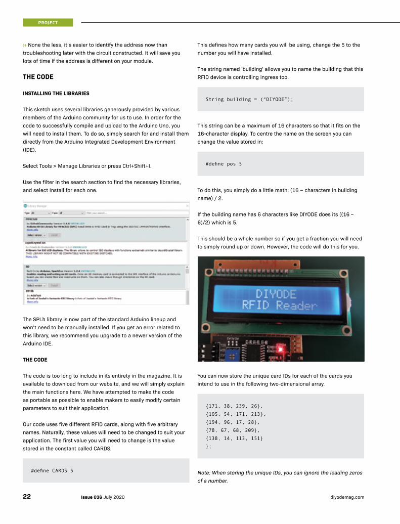
Before we move on, it’s important to double-check the address of your I2C LCD backpack. To do this, we use the I2C scanner program that you can find on the Arduino playground here: https://playground.arduino.cc/Main/I2cScanner/
With the I2C LCD connected to the Arduino, run this sketch and it will display the address of your LCD on the serial monitor. You will need to record this address as it will need to be added to this line of the main program.
You simply replace the text ‘address here’ with the hex value provided by the I2C scanner sketch. In most cases, the I2C backpack will have the address 0x26, and as such, we have left the main code as this. ››
LiquidCrystal_I2C lcd =
LiquidCrystal_I2C(address here, 16, 2);
LiquidCrystal_I2C lcd =
LiquidCrystal_I2C(0x26, 16, 2);
21Issue 036 July 2020diyodemag.com
PROJECT
››None the less, it’s easier to identify the address now than troubleshooting later with the circuit constructed. It will save you lots of time if the address is different on your module.
THE CODE
INSTALLING THE LIBRARIES
This sketch uses several libraries generously provided by various members of the Arduino community for us to use. In order for the code to successfully compile and upload to the Arduino Uno, you will need to install them. To do so, simply search for and install them directly from the Arduino Integrated Development Environment (IDE).
Select Tools > Manage Libraries or press Ctrl+Shift+I.
Use the filter in the search section to find the necessary libraries, and select Install for each one.
The SPI.h library is now part of the standard Arduino lineup and won’t need to be manually installed. If you get an error related to this library, we recommend you upgrade to a newer version of the Arduino IDE.
THE CODE
The code is too long to include in its entirety in the magazine. It is available to download from our website, and we will simply explain the main functions here. We have attempted to make the code as portable as possible to enable makers to easily modify certain parameters to suit their application.
Our code uses five different RFID cards, along with five arbitrary names. Naturally, these values will need to be changed to suit your application. The first value you will need to change is the value stored in the constant called CARDS.
#define CARDS 5
This defines how many cards you will be using, change the 5 to the number you will have installed.
The string named 'building' allows you to name the building that this RFID device is controlling ingress too.
This string can be a maximum of 16 characters so that it fits on the 16-character display. To centre the name on the screen you can change the value stored in:
To do this, you simply do a little math: (16 − characters in building name) / 2.
If the building name has 6 characters like DIYODE does its ((16 – 6)/2) which is 5.
This should be a whole number so if you get a fraction you will need to simply round up or down. However, the code will do this for you.
You can now store the unique card IDs for each of the cards you intend to use in the following two-dimensional array.
byte UID[CARDS][4] = {
Note: When storing the unique IDs, you can ignore the leading zeros of a number.
String building = (“DIYODE”);
#define pos 5
{171, 38, 239, 26},
{105, 54, 171, 213},
{194, 96, 17, 28},
{78, 67, 68, 209},
{138, 14, 113, 151}
};
Issue 036 July 2020 diyodemag.com22
PROJECT
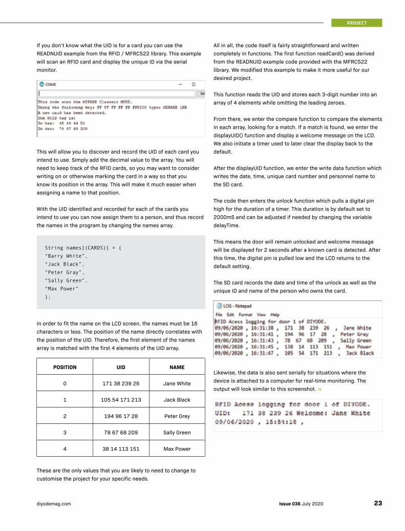
If you don’t know what the UID is for a card you can use the READNUID example from the RFID / MFRC522 library. This example will scan an RFID card and display the unique ID via the serial monitor.
This will allow you to discover and record the UID of each card you intend to use. Simply add the decimal value to the array. You will need to keep track of the RFID cards, so you may want to consider writing on or otherwise marking the card in a way so that you know its position in the array. This will make it much easier when assigning a name to that position.
With the UID identified and recorded for each of the cards you intend to use you can now assign them to a person, and thus record the names in the program by changing the names array.
In order to fit the name on the LCD screen, the names must be 16 characters or less. The position of the name directly correlates with the position of the UID. Therefore, the first element of the names array is matched with the first 4 elements of the UID array.
POSITION UID NAME
0 171 38 239 26 Jane White
1 105 54 171 213 Jack Black
2 194 96 17 28 Peter Grey
3 78 67 68 209 Sally Green
4 38 14 113 151 Max Power
These are the only values that you are likely to need to change to customise the project for your specific needs.
String names[(CARDS)] = {
“Barry White”,
“Jack Black”,
“Peter Gray”,
“Sally Green”,
“Max Power”
};
All in all, the code itself is fairly straightforward and written completely in functions. The first function readCard() was derived from the READNUID example code provided with the MFRC522 library. We modified this example to make it more useful for our desired project.
This function reads the UID and stores each 3-digit number into an array of 4 elements while omitting the leading zeroes.
From there, we enter the compare function to compare the elements in each array, looking for a match. If a match is found, we enter the displayUID() function and display a welcome message on the LCD. We also initiate a timer used to later clear the display back to the default.
After the displayUID function, we enter the write data function which writes the date, time, unique card number and personnel name to the SD card.
The code then enters the unlock function which pulls a digital pin high for the duration of a timer. This duration is by default set to 2000mS and can be adjusted if needed by changing the variable delayTime.
This means the door will remain unlocked and welcome message will be displayed for 2 seconds after a known card is detected. After this time, the digital pin is pulled low and the LCD returns to the default setting.
The SD card records the date and time of the unlock as well as the unique ID and name of the person who owns the card.
Likewise, the data is also sent serially for situations where the device is attached to a computer for real-time monitoring. The output will look similar to this screenshot. ››
23Issue 036 July 2020diyodemag.com
PROJECT

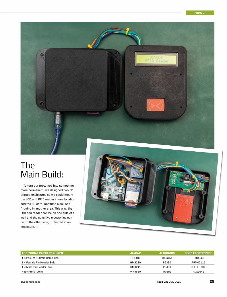
The Main Build:››To turn our prototype into something more permanent, we designed two 3D printed enclosures so we could mount the LCD and RFID reader in one location and the SD card, Realtime clock and Arduino in another area. This way, the LCD and reader can be on one side of a wall and the sensitive electronics can be on the other side, protected in an enclosure. ››
ADDITIONAL PARTS REQUIRED: JAYCAR ALTRONICS CORE ELECTRONICS1 × Pack of 100mm Cable Ties HP1196 H4031A FIT0343
1 × Female Pin Header Strip HM3230 P5390 PRT-00115
1 × Male Pin Header Strip HM3211 P5430 POLOLU-965
Heatshrink Tubing WH5520 W0882 ADA1649
25Issue 036 July 2020diyodemag.com
PROJECT
LCD-I2C-CONVERTER
RTC-EEPROM-BATTERY
CARD-SD-ADAPTER
D0D1D2*D3D4*D5*D6D7D8*D9
*D10*D11D12D13
A0A1A2A3A4A5VINRESET
5VAREFGN
DGN
DGN
D
3.3V
IOREF
SDASCL
VCCM
ISOM
OSISCKRESETGN
D
GND
J1.4
SCLJ1.3
SDAJ1.2
VCCJ1.1
VSS J2.1VDD J2.2VEE J2.3RS J2.4R/W J2.5
DB0 J2.7DB1 J2.8DB2 J2.9DB3 J2.10DB4 J2.11DB5 J2.12DB6 J2.13DB7 J2.14LED.A J2.15LED.K J2.16
EN J2.6
GND.1
J1.1VCC.1
J1.2SDA.1
J1.3SCL.1
J1.4DS.1
J1.5
BATJ2.1
GND.2
J2.2VCC.2
J2.3SDA.2
J2.4SCL.2
J2.5DS.2
J2.6SQ
J2.7
GND.1
1
3V33
5V5
CS7
MOSI
9
SCK11
MISO
13
GND.2
15
12345678
RFID MODULE
ARDUINO UN
O R3
VCC.1J1.3
IN1
J1.2
GND
J1.1
VCC.2J2.2
JD-VCCJ2.1
RELAY-1-SRD
3.3VRSTGNDMISOMOSISCLKNSSIRQ
SD CARD
K1
Connect the relay to yoursolenoid/door control hardware
Issue 036 July 2020 diyodemag.com26
PROJECT
››3D PRINTED ENCLOSURE
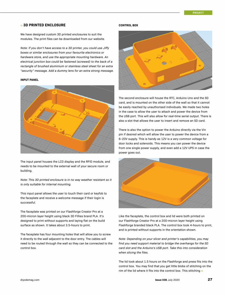
We have designed custom 3D printed enclosures to suit the modules. The print files can be downloaded from our website.
Note: If you don’t have access to a 3D printer, you could use Jiffy boxes or similar enclosures from your favourite electronics or hardware store, and use the appropriate mounting hardware. An electrical junction box could be fastened (screwed) to the back of a rectangle of brushed aluminium or stainless steel sheet for an extra "security" message. Add a dummy lens for an extra strong message.
INPUT PANEL
The input panel houses the LCD display and the RFID module, and needs to be mounted to the external wall of your secure room or building.
Note: This 3D printed enclosure is in no way weather resistant so it is only suitable for internal mounting.
This input panel allows the user to touch their card or keyfob to the faceplate and receive a welcome message if their login is successful.
The faceplate was printed on our Flashforge Creator Pro at a 200-micron layer height using black 3D Fillies brand PLA. It’s designed to print without supports and laying flat on the build surface as shown. It takes about 3.5-hours to print.
The faceplate has four mounting holes that will allow you to screw it directly to the wall adjacent to the door entry. The cables will need to be routed through the wall so they can be connected to the control box.
CONTROL BOX
The second enclosure will house the RTC, Arduino Uno and the SD card, and is mounted on the other side of the wall so that it cannot be easily reached by unauthorised individuals. We made two holes in the case to allow the user to attach and power the device from the USB port. This will also allow for real-time serial output. There is also a slot that allows the user to insert and remove an SD card.
There is also the option to power the Arduino directly via the Vin pin if desired which will allow the user to power the device from a 6–20V supply. This is handy as 12V is a very common voltage for door locks and solenoids. This means you can power the device from one single power supply, and even add a 12V UPS in case the power goes out.
Like the faceplate, the control box and lid were both printed on our Flashforge Creator Pro at a 200-micron layer height using Flashforge branded black PLA. The control box took 4-hours to print, and is printed without supports in the orientation shown.
Note: Depending on your slicer and printer’s capabilities, you may find you need support material to bridge the overhangs for the SD card slot and the Arduino’s USB port. Take this into consideration when slicing the files.
The lid took about 1.5 hours on the Flashforge and press fits into the control box. You may find that you get little blobs of stitching on the rim of the lid where it fits into the control box. This stitching ››
27Issue 036 July 2020diyodemag.com
PROJECT
››is a seam where the 3D printer transitions from one layer to the next. If your slicer does this in the same position on every layer you get a very noticeable seam running vertically along the print. This seam may cause the lid to not fit correctly. If this is an issue for you, you can use a hobby knife to carefully remove the little extra plastic.
To help reduce the amount of work required to remove this seam, make sure your slicer is not set to starting and stopping each layer at a random spot.
Note: Some small issues were discovered during the assembly and the design has been modified to rectify these issues, thus you may notice some slight differences between the images here and the files you will be printing.
PROJECT ASSEMBLY
To assemble the project, we need to create a simple wiring harness that will connect each component to the Arduino Uno. This was quite possibly the most time-consuming part of the project. You need to make the cables as short as practical to reduce wastage and filling the control box with coils of wire. The best way we found to do this was to first attach the modules to the enclosure in their positions.
Screw the Arduino down with just one screw as you will need to remove the Uno later to run the cables through the hole in the back of the enclosure. This hole is designed to line up with a hole in the wall it’s mounted to, which will allow the cables to link both units.
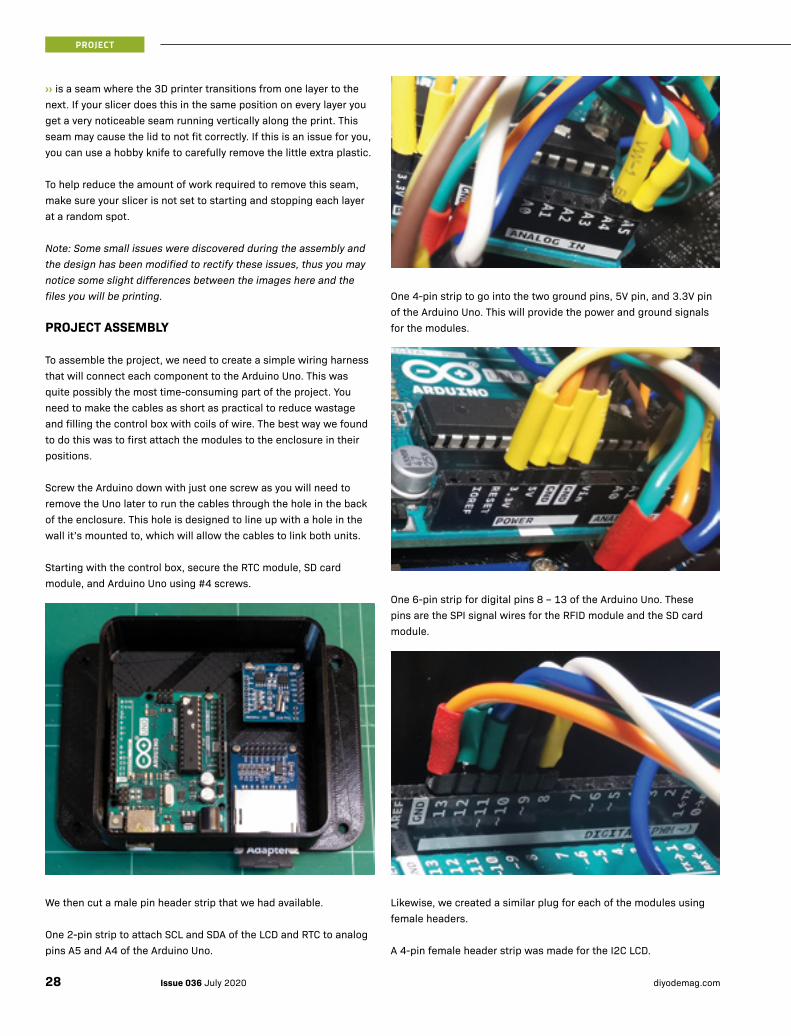
Starting with the control box, secure the RTC module, SD card module, and Arduino Uno using #4 screws.
We then cut a male pin header strip that we had available.
One 2-pin strip to attach SCL and SDA of the LCD and RTC to analog pins A5 and A4 of the Arduino Uno.
One 4-pin strip to go into the two ground pins, 5V pin, and 3.3V pin of the Arduino Uno. This will provide the power and ground signals for the modules.
One 6-pin strip for digital pins 8 – 13 of the Arduino Uno. These pins are the SPI signal wires for the RFID module and the SD card module.
Likewise, we created a similar plug for each of the modules using female headers.
A 4-pin female header strip was made for the I2C LCD.
Issue 036 July 2020 diyodemag.com28
PROJECT

An 8-pin female header strip was made for the SPI SD card module (only 6 wires were connected).
A 4-pin female header strip was made for the I2C RTC module.
An 8-pin female header strip was made for the SPI RFID module (Only 7 pins were used).
To join the wires, we first stripped about 10mm of the insulation away, giving us plenty of room to work. We then placed two wires parallel to each other and twisted the exposed wires together to form a strong mechanical bond. We then slid a 20mm length of heatshrink over these two wires (to insulate the join after soldering). We then twisted the third wire around these two and soldered all three wires together.
Once soldered you can insulate the join by sliding the heatshrink over the solder connection and apply heat to shrink it. You can also use electrical tape or liquid electrical tape if you wish. This technique will produce a very strong join for three wires, and will need to be used on most connections in this project. Take your time and you will get great results.
Once you’re done, you can simply use the male and female pin headers as a plug and socket to join all of the modules to the Arduino Uno.
Note: The wires for the RFID module and LCD need to be routed underneath the Arduino Uno and through a hole on the bottom of the controller enclosure.
When everything is placed and working correctly you should use cable/zip ties to keep the wires in check and to prevent twisting, knots or strain on connections.
PROGRAMMING
If you’re new to Arduino or having issues getting started you may want to check out our "Setting up the Arduino IDE guide" from Issue 17 where we go through the fundamentals of using the Arduino from the install process to adding libraries and uploading a sketch on various different operating systems. You can find it here: https://diyodemag.com/education/fundamentals_setting_up_the_arduino_ide ››
29Issue 036 July 2020diyodemag.com
PROJECT

››TESTING & TROUBLESHOOTING
Testing the prototype is fairly straightforward for this project. We have added some basic error messages to help identify potential faults. Below are the potential errors and how to rectify them.
BLANK LCD
If there is no information displayed on the LCD, your first action should be to adjust the potentiometer on the back of the I2C backpack module. This potentiometer adjusts the contrast of the display and should make the display visible.
If this does not rectify the display issues, double-check the connections. Make sure the SDA, SCL and power and ground connections are correct. If the fault is still not rectified, ensure that the code has been correctly uploaded to the microcontroller.
You should also double-check that the address set in the code matches the address of the LCD. You can use the Arduino playground I2C scanner to do this, as mentioned earlier.
RTC FAILURE
This error message will be displayed on the LCD if there is an issue with communication between the microcontroller/Arduino and the RTC module. This would normally occur if the SCL and SDA connections are incorrectly connected, or insufficient power is being delivered to the module.
Double-check all connections and rectify any potential issues. If this error persists, consider switching the module to ensure it is functioning correctly.
NO SD CARD
If you see ‘No SD Card’ displayed on the LCD, the most likely cause is that the SD card has not been inserted or is the wrong format. Make sure that the SD card is correctly inserted and that the formatting is in the FAT16 or FAT32 (file allocation table) format. Most SD cards come supplied from the factory in this format, however, if the SD card has been used in other devices such as a camera or media player etc., you may need to reformat it.
If that still does not rectify the fault double-check that the wiring is correct and that the modules are receiving the correct voltage.
WHERE TO FROM HERE?
As a door access and logging device there isn’t too far to push this project. Naturally, making it wireless and recording the data to an online cloud would be the most obvious improvement. However, the technology used is both pretty impressive and prevalent. Using just the objects on hand, we were able to retrieve data from a Queensland driver's license, a United Kingdom passport, public transport cards, Visa payWave cards and various student IDs. In fact, its highly likely that this reader will work with any RFID chips designed to run on the 13.56MHz frequency. Of course, the data is always going to be encrypted, and thus it is only for an educational benefit. ■
WANT MORE?For the code and 3D print files, or to discuss this project, visit:https://diyode.io/036xpyy
Issue 036 July 2020 diyodemag.com30
PROJECT

Power Up Your Projects.Sale ends July 31st.
Order online @ altronics.com.au | Sale pricing ends July 31st 2020.
Build It Yourself Electronics Centres®
D 2322
$68.95 Build wireless charging into your desk An ultra-slim desk mount 10W wire-less fast charger. Requires 60mmØ hole. Includes power adaptor & USB cable.
NEW!
D 2323
$135 Desk Mount Power Delivery Charger A 96W USB type C charger, plus dual QC 3.0 USB charging in the one compact near flush mount unit. Re-quires 60mmØ mount-ing hole. Includes power supply.
Charges a laptop, a
phone & tablet at the same
tim!
See notifications while you recharge.Handy upright 15W wireless charging stand allows you to read in-coming notifications at a glance without having to stop charging. Requires QC3.0 USB wall charger (such as our M8863)
$45.95
D 2324
30 x 30 x 40cm build volume for
larger prints
The CR-10 offers reliable large volume printing up to 30Wx30Dx40Hcm! The dual port fan cooled hot end offers reliable and precise print quality whilst the triangular design provides excellent stability. Heated print bed reduces warping, ensuring great prints every time.
K 8606
$1095
Print bigger with the Creality® CR-10 V2 3D Printer
Includes BONUS 1kg roll of
PLA filament in your choice
of colour Valued at $49.95
Wireless Charger Alarm ClockA stylish bedside or desktop clock with in-built 10W wireless charging for your phone & 8 colour night light. Clock auto dims at night time. Dual alarms so you’ll always wake up on time! USB output also lets you to charge your watch. Size: 140x117x73mm.
D 2320
$63.95NEW!
ADD ON DEAL: USB QC 3.0 wall charger for $15 (M 8863)
Cut, Polish, Grind, Sand & Carve.Great for finishing and smoothing your 3D prints! Perfect for odd jobs and hobbies. Powerful 130W motor with variable speed between 8000 and 33000 RPM. Included is a 172pc accessory kit of grinding wheels, drills, cutters, sanding discs, polishing pads and more!
T 2120
$75SAVE 13%
Get creating this winter with these deals...
Premium sound in a tiny package.Redback® 2.75” Mini Satellite Speakers. Deliver full and rich sound you’d hardly believe these speakers are only 10cm tall! They’re the perfect home and small commercial sound solution - especially when paired with our C 5201 active subwoofer and A 4860 bluetooth amplifier. 8Ω 10W rated. C 5285
Includes easy to mount
ball joint bracket
$160pr
C 9044
Flexible Wireless Sports Headphones Great sound and even better battery life! These over ear style headphones offer up to 16 hours listening time in a super comfortable & compact design. Bluetooth 5.0 for great range and audio quality.
$63.25
Listen while you walk, run or ride!
USB Data ProtectorAllows you to protect your device from possible data theft or malware when recharging from public USB ports, such as those on public transport or airports.
NEW!
$11.50
P 1920A
Broken remote? No problem!Dog ate your remote? Enthusiastic toddler binged too hard on Paw Patrol? This handy replacement features IR learning plus pre-programmed codes for 100’s of popular equipment brands.
NEW!
$34.50A 1012A

See last page for store locations or visit altronics.com.au Sale pricing ends July 31st 2020.
Solar MPPT & 25A DC Battery ChargerThis dual input design connects to a solar panel and your cars alternator (12 or 24V) to provide 3 stage charging for secondary batteries such as those used in campers, caravans and trades service vans/trailers. It is compatible with the latest smart alternators and start/stop systems found in modern vehicles. A unique vibration activation sensor simplifies wiring so that it won’t void vehicle warranty. Suitable for Lead Acid, AGM and Lithium Fe PO4 batteries.
N 2088
$345NEW!
Inflate a tyre. Start a flat battery.Great for the 4WD/car enthusiast. Features a 16800mAh battery bank plus emergency compressor to top up tyres (max 8 mins run time). Provides 600A peak battery cranking output. 12/16/19V & USB output for powering devices.
M 8198
Includes jump starter
& air com-pressor
$119SAVE $50
Latest home & car power accessories.
Simple Motor Speed ControllerThis commonly requested module can be used as a motor speed controller or light dimmer for 12V DC circuits up to 8A current. Offers smooth PWM control from 0-100% with easy in-line connection.
N 2097
NEW!$51.75
Mini Solar Charge ControllerUltra compact design with for 12V panels. 3A charging output. Ideal for panels 40W or less.
N 2003
NEW!$17.25
Using mains power in the field? Protect yourself with an RCD power block.A must have for trades in the field or at home in the workshop - protects users from appliance faults just like your home RCD switch. It’s also a great safety item for use with 240V inverters with RV’s and campers. In-built USB sockets for charging your devices, plus 1.8m cord. Easy to reset with surge protected outlets.
P 8172 10A & 15A Skt.
P 8176 3 x 10A, 2x 15A Skt.
NEW! $109
P 8174 5 x 10A Skt.
$120
$155
Need an extra laptop charger?This 90W USB-C power delivery (PD) charger offers fast recharging for MacBooks, Nintendo Switch and other type “C” devices. Plus a standard 2.4A USB charger output.
M 8994 Charges any USB-C laptop
$105NEW!
M 8010A 150VA
Power mains appliances on the road!• Delivers pure AC power from your car battery • Ideal for tricky loads, such as laptops, & game consoles • USB charging output • 12V input • M 8010A 300W surge rated, 170x108x60mm • M 8012A 800W surge rated, 200Lx108Wx60Hmm
M 8012A 400VA
SAVE $50
$239 $165
Charge 8 USB devices at once.Got a family full of devices? This handy charger outputs up to 12A or charging current to keep all your tablets and phones juiced up! Includes power cord.
M 8881
SAVE 32%
$44
Top deal!
Handy power products for custom projects...
DC-DC Converter ModuleAllows a low input voltage (3.5-35V) to be increased to a higher output (5-25V). Easy to inline connection. 2A continuous.
Z 6338
SAVE 24%
$13
DC-DC Boost ModuleAllows a 3-34V DC input to be boosted up between 4-35VDC. 2A rated. Input/output voltage display. Z 6339
SAVE 20%
$20DC-DC Buck ModuleGenerate a lower voltage output from a higher supply. 3-40V DC in, 1.5-35V DC out. 3A max.
Z 6334
$9.15
Power USB projects over ethernet!• Power a micro USB device over 802.3af PoE. • Eliminates the need for a power supply at the end of the cable run. • 5V 2.4A max.
S 9265
SAVE 20%
$18
Battery Power Backup BoxA complete 12V DC back up unit for powering devices from internal battery. when mains fails. Suits 7.2Ah battery (S 4540 $34.95). Mains lead included. M 8561
Includes MPPT circuitry to
get the most juice out of
your solar panels!
$120SAVE $29
Jumbo QC3.0/USB C Power BankOffering both the latest QuickCharge 3.0 charging and 18W USB-C PD output, this enormous 20,000mAh power bank will keep your devices charged away from mains power. 136x70x25mm
D 0511B
NEW!
$79.95
Recharges faster thanks
to USB C input!Easy to use 6V/12V SLA battery chargerWith trickle charging function to ensure long battery life. Multi-stage charge control ensures long life from your batteries. 6/12V 1.3-8Ah.
M 8520A
SAVE 26%
$24
AA/AAA x 10 Home Battery ChargerCLEARANCE DEAL! SAVE 40%Recharges 10xAA/AAA or 2x9V batteries. Includes mains power supply & car adapter. Suits NiMH only.
A 0276
SAVE $30
$39.95

T 1528A
Wire Stripper & Kwik CrimperCombines a ratchet wire stripper, cutting blade & kwik crimper (red, blue and yellow sheaths). Suits 10-24 AWG cable.
SAVE 15%
$33Toolbox space saver!
Buying for business? Save with a VIP-Trade Card Sale pricing ends July 31st 2020.
RCD Mains GPO TesterTests mains power points for correct operation with simulation of an earth leakage to test your household RCD. Indicates unsafe wiring. A must have for electricians.
NEW!
$40 P 8142
Build the ultimate electronics tool kit.
Provides 300W of hot air for quick and easy desolder and re-work of surface mount boards. Melts solder in seconds allowing you to remove devices easily. 200-500°C adjustable. Includes desk stand - plus narrow, medium and wide nozzles for different tasks.
T 1289
9999 Count True RMS DMMWith in-built AC mains detection. Featuring a striking easy to read reverse backlit screen and a massive 9999 count readout. Auto ranging with easy push button operation. Great price & build quality.
SAVE $25
Q 1090
$160SMD Hot Air Re-Work
Desoldering Gun
NEW!
Not just for desoldering -
works great as a
regular hot air gun!
$80
Precision Tap & Die SetA precision machined tap and die set for creating metric thread holes and bolts. M3 to M12 sizes.
T 1422
NEW!
$45.95
Handy for cleaning and
restoring threads.
30W Lithium ‘Go Anywhere’ Soldering Iron45 minute run time. 600°C max. Ideal for occasional soldering jobs or light duty repairs and field servicing. Recharge by USB power adaptor in your car or at home - or USB battery bank. Includes replaceable 18650 battery.
T 2694A
SAVE $50
INCLUDES ACCESSORY PACK: • 3 tips: conical, hot knife/3D print finishing tool, hot air • Micro USB cable • Solder container & 1m of solder • Tip sponge.
$155
Quality Resin Core Solder Premium grade for leaded soldering. 200gm reels. 60% tin, 40% lead.
T 1100 0.8mm, T 1110 1.0mm, T 1122 1.6mm
$14a roll SAVE
15%
Blast away dirt & grime on partsAt just $70 this ultrasonic cleaner is great value for your workbench. Clean small parts, jewellery, shaver heads, glasses and more! Shifts grease, dust and gunk from tiny crevices in just minutes. Tank size: 155x98x52mm.
X 0102
Makes jewellery sparkle again!
$70SAVE $15
A pocket sized 3x magnifier with LED illumination. Great for hobbies & repairs. Re-quires 3xAAA batteries.
Portable Pop-Up Mini Magnifier
NEW!
$17.25
X 0431
T 2487A 50W
SAVE 24%
$30
T 2483 80W
SAVE 24%
$22
T 2440 60W
SAVE 20%
$18Micron® Handheld Mains Soldering IronsAn iron for every occasion! T 2440 is ideal for general purpose soldering. T 2487A features adjustable temperature for sensitive work. T 2483 is a heavy duty chisel iron for tinning large cable, terminals and joins.
Desktop Fume ExtractorA must have for any soldering or 3D printing work space. Whisks away fumes and filters the air through active carbon filter pads (3 included). 115CFM air flow with low noise ball bearing fan.
NEW!
$145T 1295A
120mm long life high flow
fan
All-Rounder Student DMMThe perfect beginner, student or enthusiast multimeter. 12 auto ranging test modes with good accuracy and an easy to read jumbo digit 4000 count screen. Includes test leads.
SAVE 18%
$33Q 1129
Audio Signal GeneratorA useful pocket sized signal generator for servicing of audio equipment. Generates sine and square waveforms in 46 preset frequencies from 20Hz to 150kHz in two ranges.
SAVE $36
$99Q 1542Get started in electronics with this handy 20pc kit. A jam packed starter kit including soldering iron, multimeter, solder sucker, wire stripper, cutters, pliers and more! Ideal for beginners & enthusiasts.
$69SAVE 20%
T 2163
T 2486
Mini Blow Torch A 1300°C blow torch with adjustable gas feed for a variety of tasks such as brazing and model making.
Don’t forget
the gas! T 2451 $9.35
SAVE 22%
$35
See last page for store locations or visit altronics.com.au Sale pricing ends July 31st 2020.
Solar MPPT & 25A DC Battery ChargerThis dual input design connects to a solar panel and your cars alternator (12 or 24V) to provide 3 stage charging for secondary batteries such as those used in campers, caravans and trades service vans/trailers. It is compatible with the latest smart alternators and start/stop systems found in modern vehicles. A unique vibration activation sensor simplifies wiring so that it won’t void vehicle warranty. Suitable for Lead Acid, AGM and Lithium Fe PO4 batteries.
N 2088
$345NEW!
Inflate a tyre. Start a flat battery.Great for the 4WD/car enthusiast. Features a 16800mAh battery bank plus emergency compressor to top up tyres (max 8 mins run time). Provides 600A peak battery cranking output. 12/16/19V & USB output for powering devices.
M 8198
Includes jump starter
& air com-pressor
$119SAVE $50
Latest home & car power accessories.
Simple Motor Speed ControllerThis commonly requested module can be used as a motor speed controller or light dimmer for 12V DC circuits up to 8A current. Offers smooth PWM control from 0-100% with easy in-line connection.
N 2097
NEW!$51.75
Mini Solar Charge ControllerUltra compact design with for 12V panels. 3A charging output. Ideal for panels 40W or less.
N 2003
NEW!$17.25
Using mains power in the field? Protect yourself with an RCD power block.A must have for trades in the field or at home in the workshop - protects users from appliance faults just like your home RCD switch. It’s also a great safety item for use with 240V inverters with RV’s and campers. In-built USB sockets for charging your devices, plus 1.8m cord. Easy to reset with surge protected outlets.
P 8172 10A & 15A Skt.
P 8176 3 x 10A, 2x 15A Skt.
NEW! $109
P 8174 5 x 10A Skt.
$120
$155
Need an extra laptop charger?This 90W USB-C power delivery (PD) charger offers fast recharging for MacBooks, Nintendo Switch and other type “C” devices. Plus a standard 2.4A USB charger output.
M 8994 Charges any USB-C laptop
$105NEW!
M 8010A 150VA
Power mains appliances on the road!• Delivers pure AC power from your car battery • Ideal for tricky loads, such as laptops, & game consoles • USB charging output • 12V input • M 8010A 300W surge rated, 170x108x60mm • M 8012A 800W surge rated, 200Lx108Wx60Hmm
M 8012A 400VA
SAVE $50
$239 $165
Charge 8 USB devices at once.Got a family full of devices? This handy charger outputs up to 12A or charging current to keep all your tablets and phones juiced up! Includes power cord.
M 8881
SAVE 32%
$44
Top deal!
Handy power products for custom projects...
DC-DC Converter ModuleAllows a low input voltage (3.5-35V) to be increased to a higher output (5-25V). Easy to inline connection. 2A continuous.
Z 6338
SAVE 24%
$13
DC-DC Boost ModuleAllows a 3-34V DC input to be boosted up between 4-35VDC. 2A rated. Input/output voltage display. Z 6339
SAVE 20%
$20DC-DC Buck ModuleGenerate a lower voltage output from a higher supply. 3-40V DC in, 1.5-35V DC out. 3A max.
Z 6334
$9.15
Power USB projects over ethernet!• Power a micro USB device over 802.3af PoE. • Eliminates the need for a power supply at the end of the cable run. • 5V 2.4A max.
S 9265
SAVE 20%
$18
Battery Power Backup BoxA complete 12V DC back up unit for powering devices from internal battery. when mains fails. Suits 7.2Ah battery (S 4540 $34.95). Mains lead included. M 8561
Includes MPPT circuitry to
get the most juice out of
your solar panels!
$120SAVE $29
Jumbo QC3.0/USB C Power BankOffering both the latest QuickCharge 3.0 charging and 18W USB-C PD output, this enormous 20,000mAh power bank will keep your devices charged away from mains power. 136x70x25mm
D 0511B
NEW!
$79.95
Recharges faster thanks
to USB C input!Easy to use 6V/12V SLA battery chargerWith trickle charging function to ensure long battery life. Multi-stage charge control ensures long life from your batteries. 6/12V 1.3-8Ah.
M 8520A
SAVE 26%
$24
AA/AAA x 10 Home Battery ChargerCLEARANCE DEAL! SAVE 40%Recharges 10xAA/AAA or 2x9V batteries. Includes mains power supply & car adapter. Suits NiMH only.
A 0276
SAVE $30
$39.95

© Altronics 2020. E&OE. Prices stated herein are only valid until date shown or until stocks run out. Prices include GST and exclude freight and insurance. See latest catalogue for freight rates.
Sale Ends July 31st 2020Phone: 1300 797 007 Fax: 1300 789 777Mail Orders: [email protected]
Build It Yourself Electronics Centres
Western Australia» Perth: 174 Roe St 08 9428 2188
» Balcatta: 7/58 Erindale Rd 08 9428 2167
» Cannington: 5/1326 Albany Hwy 08 9428 2168
» Midland: 1/212 Gt Eastern Hwy 08 9428 2169
» Myaree: 5A/116 N Lake Rd 08 9428 2170
Victoria» Springvale: 891 Princes Hwy 03 9549 2188
» Airport West: 5 Dromana Ave 03 9549 2121
New South Wales» Auburn: 15 Short St 02 8748 5388
Queensland» Virginia: 1870 Sandgate Rd 07 3441 2810
South Australia» Prospect: 316 Main Nth Rd 08 8164 3466
Please Note: Resellers have to pay the cost of freight & insurance. Therefore the range of stocked products & prices charged by individ-ual resellers may vary from our catalogue.
Find a local reseller at: altronics.com.au/resellers
B 00
91
The gear to keep you creating!Creality® Premium PLA FilamentWe’re now stocking Creality’s premium 1.75mm PLA designed for use in many brands of 3D printer on the market. Creality have focused on making top quality non toxic filaments with a tolerance of just 0.02mm. Each filament is 100% bubble free and offers excellent tensile strength & fluidity. This all adds up to more reliable prints and less waste!
$49.95per kg.
n K 8387A Silver n K 8388A Goldn K 8389A Pinkn K 8391A Orangen K 8392A Greenn K 8393A Yellow
n K 8394A Purplen K 8395A Bluen K 8396A Red n K 8397A Blackn K 8398A Greynn K 8399A White
Made from high quality materials for less brittle
filament breakages.
K 9615
Arduino Starter Platform Kit A handy starter kit for educators or Arduino newbies. Includes an Arduino UNO compatible board, blue acrylic base, 5V 2A power supply, USB lead, breadboard, 65pcs of jumper leads & hardware.
SAVE 10%
$45
Bare Conductive® Paint Jar Paint real circuits on almost any surface! Great for repairs or experimenting. 50ml jar.
T 3133
$49.95Freezer Spray Non-flammable freezing spray. Useful for rapid detection of tem-perature dependent circuit faults, testing thermal sensors etc. 300g.
T 3084A $20.95High Temperature Polyimide TapeGreat for 3D printing, leaves no residue in high temperature masking applications.
Model Width NOWT 2971A 8mm $9.75
T 2972A 12mm $12T 2973A 16mm $13.50
T 2974A 19mm $15T 2975A 24mm $17T 2976A 36mm $25
SAVE 15%
Single Sided Copper TapeA multitude of electronic uses - create low-profile component traces, RF-shielding, antennas etc. Also great for stick on circuits. 0.07mm thick. 15m length.
T 2980A 5mm T 2982A 50mm
SAVE 22%
$40SAVE 22%
$7
World Famous DeoxIT® Sprays The gold standard in electronic servicing sprays. Deoxidises, cleans, preserves contacts & joins (Fader F5 even works on con-ductive plastic faders controls!). A must have for servicing and restor-ation. 142g.
T 3062 Fader F5
$49.50
T 3063 Deoxit D5$44.95
The ultimate
magic ‘fix-it’sprays
Red Raspberry Pi® 4 Aluminium CasesAvailable in dual fan cooled or passive cooled versions. These cases provide protection and thermal dissipation for your Pi 4.
H 8959 Dual Fan
$39.95
H 8954 Passive
$29.95
NEW!
Breadboard PCB BlanksAllows you to keep the same PCB layout as your breadboard design. Solder masked & screened.
$7
H 0703 164x64mm
$10
H 0701 94x64mm
SAVE12%
Computer Hardware KitA handy 228pc set of common computer for hard drives, motherboard standoffs and cooling fans.
$22.95
D 0010Includes
hard to find HDD
screws
W 0884A
Heatshrink Mega Pack 171pcs of 75mm & 45mm lengths in a range of colours & sizes (3.2 to 12.7mm). 2:1 shrink ratio.
$19SAVE 15%
Raspberry Pi® Zero W Starter KitThe Pi Zero W offers amazing power and features from a compact board including Bluetooth and 802.11b/g /n wi-fi. Kit includes Zero W board, case, HDMI & USB adaptors.
Z 6303A
$47.95
Ultra compact
version of the Raspberry
Pi
WIRELESS SWITCHING
Multi-zone WiFi Controlled Switch
using ESP8266
FRASER BORDEREngineer | Educator | Founder of IntegratedSTEM
& DIYODE Staff Writer
integratedstem.com.au
BASEM ADELLead Engineer at IntegratedSTEM
& DIYODE Staff Writer
integratedstem.com.au
Control multiple systems distributed across your WiFi network at the
touch of just one button.
BUILD TIME: 30 MINUTES (+ 3D PRINTING TIME) DIFFICULTY RATING: INTERMEDIATE
Issue 036 July 2020diyodemag.com 35
PROJECT
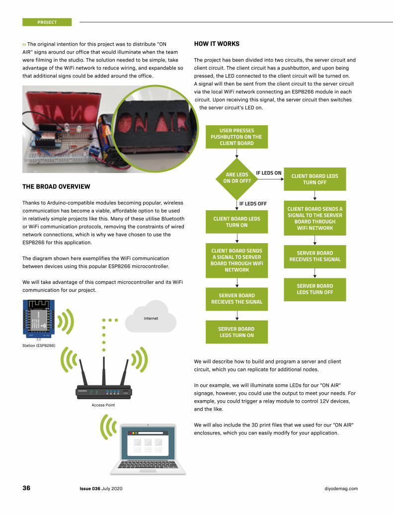
››The original intention for this project was to distribute “ON AIR” signs around our office that would illuminate when the team were filming in the studio. The solution needed to be simple, take advantage of the WiFi network to reduce wiring, and expandable so that additional signs could be added around the office.
THE BROAD OVERVIEW
Thanks to Arduino-compatible modules becoming popular, wireless communication has become a viable, affordable option to be used in relatively simple projects like this. Many of these utilise Bluetooth or WiFi communication protocols, removing the constraints of wired network connections, which is why we have chosen to use the ESP8266 for this application.
The diagram shown here exemplifies the WiFi communication between devices using this popular ESP8266 microcontroller.
We will take advantage of this compact microcontroller and its WiFi communication for our project.
Internet
Access Point
Station (ESP8266)
RST
A0
D0
D5
D6
D7
D8
3V3
TX
RX
D1
D2
D3
D4
GND
5V
RESET D1 mini
HOW IT WORKS
The project has been divided into two circuits, the server circuit and client circuit. The client circuit has a pushbutton, and upon being pressed, the LED connected to the client circuit will be turned on. A signal will then be sent from the client circuit to the server circuit via the local WiFi network connecting an ESP8266 module in each circuit. Upon receiving this signal, the server circuit then switches
the server circuit’s LED on.
We will describe how to build and program a server and client circuit, which you can replicate for additional nodes.
In our example, we will illuminate some LEDs for our "ON AIR" signage, however, you could use the output to meet your needs. For example, you could trigger a relay module to control 12V devices, and the like.
We will also include the 3D print files that we used for our "ON AIR" enclosures, which you can easily modify for your application.
USER PRESSESPUSHBUTTON ON THE
CLIENT BOARD
CLIENT BOARD LEDSTURN OFF
CLIENT BOARD LEDSTURN ON
SERVER BOARDRECIEVES THE SIGNAL
SERVER BOARDRECEIVES THE SIGNAL
SERVER BOARDLEDS TURN OFF
SERVER BOARD LEDS TURN ON
ARE LEDSON OR OFF?
IF LEDS ON
IF LEDS OFF
CLIENT BOARD SENDSA SIGNAL TO SERVER
BOARD THROUGH WiFi NETWORK
CLIENT BOARD SENDS A SIGNAL TO THE SERVER
BOARD THROUGH WiFi NETWORK
Issue 036 July 2020 diyodemag.com36
PROJECT
FEATURES:
• 802.11 b/g/n
• WiFi Direct (P2P), soft-AP
• Integrated TCP/IP protocol stack
• Integrated TR switch, balun, LNA, power amplifier and matching network
• Integrated PLLs, regulators, DCXO and power management units
• +19.5dBm output power in 802.11b mode
• Power down leakage current of <10µA
• Integrated low power 32-bit CPU could be used as an application processor
• SDIO 1.1 / 2.0, SPI, UART
• STBC, 1×1 MIMO, 2×1 MIMO
• Flash: 4M
• A-MPDU & A-MSDU aggregation & 0.4ms guard interval
• Wake up and transmit packets in < 2ms
• Standby power consumption of < 1.0mW (DTIM3)
ESP8266 PINOUT ››
PIN DESCRIPTION IC INTERNAL PIND0 I/O, Interrupt, PWM, I2C GPIO16D1 I/O, SCL of I2C in default mode GPIO5D2 I/O, SDA of I2C in default mode GPIO4D3 I/O, Pull-up and enter flash mode at low power GPIO0D4 I/O, Pull-up GPIO2D5 I/O, SPI clock GPIO14D6 I/O, SPI MISO GPIO12D7 I/O, SPI MISO GPIO13D8 I/O, Dropdown, SPI, Default Slice Selection (SS) GPIO15A0 AD input, 0-3.3V ADC
ESP8266 WIFI MODULE
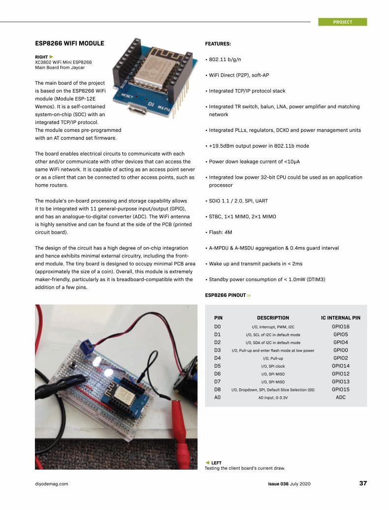
RIGHT ►XC3802 WiFi Mini ESP8266 Main Board from Jaycar
The main board of the project is based on the ESP8266 WiFi module (Module ESP-12E Wemos). It is a self-contained system-on-chip (SOC) with an integrated TCP/IP protocol. The module comes pre-programmed with an AT command set firmware.
The board enables electrical circuits to communicate with each other and/or communicate with other devices that can access the same WiFi network. It is capable of acting as an access point server or as a client that can be connected to other access points, such as home routers.
The module’s on-board processing and storage capability allows it to be integrated with 11 general-purpose input/output (GPIO), and has an analogue-to-digital converter (ADC). The WiFi antenna is highly sensitive and can be found at the side of the PCB (printed circuit board).
The design of the circuit has a high degree of on-chip integration and hence exhibits minimal external circuitry, including the front-end module. The tiny board is designed to occupy minimal PCB area (approximately the size of a coin). Overall, this module is extremely maker-friendly, particularly as it is breadboard-compatible with the addition of a few pins.
◄LEFTTesting the client board's current draw.
37Issue 036 July 2020diyodemag.com
PROJECT
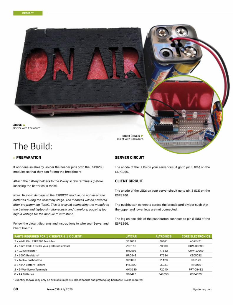
The Build:››PREPARATION
If not done so already, solder the header pins onto the ESP8266 modules so that they can fit into the breadboard.
Attach the battery holders to the 2-way screw terminals (before inserting the batteries in them).
Note: To avoid damage to the ESP8266 module, do not insert the batteries during the assembly stage. The modules will be powered after programming (later). This is to avoid connecting the module to the battery and laptop simultaneously, and therefore, applying too high a voltage for the module to withstand.
Follow the circuit diagrams and instructions to wire your Server and Client boards.
SERVER CIRCUIT
The anode of the LEDs on your server circuit go to pin 5 (D5) on the ESP8266.
CLIENT CIRCUIT
The anode of the LEDs on your server circuit go to pin 3 (D3) on the ESP8266.
The pushbutton connects across the breadboard divider such that the upper and lower legs are not connected.
The leg on one side of the pushbutton connects to pin 5 (D5) of the ESP8266.
PARTS REQUIRED FOR 1 X SERVER & 1 X CLIENT: JAYCAR ALTRONICS CORE ELECTRONICS2 x Wi-Fi Mini ESP8266 Modules XC3802 Z6381 ADA2471
4 x 5mm Red LEDs (Or your preferred colour) ZD0150 Z0800 COM-09590
1 × 10kΩ Resistor* RR0596 R7582 COM-10969
2 x 100Ω Resistors* RR0548 R7534 CE05092
1 x Tactile Pushbutton SP0600 S1120 FIT0179
2 x 4xAA Battery Holders PH9200 S5031 FIT0079
2 x 2-Way Screw Terminals HM3130 P2040 PRT-08432
8 x AA Batteries SB2425 S4955B CE04629
RIGHT (INSET) ►Client with Enclosure.
ABOVE ▲Server with Enclosure.
* Quantity shown, may only be available in packs. Breadboards and prototyping hardware is also required.
Issue 036 July 2020 diyodemag.com38
PROJECT
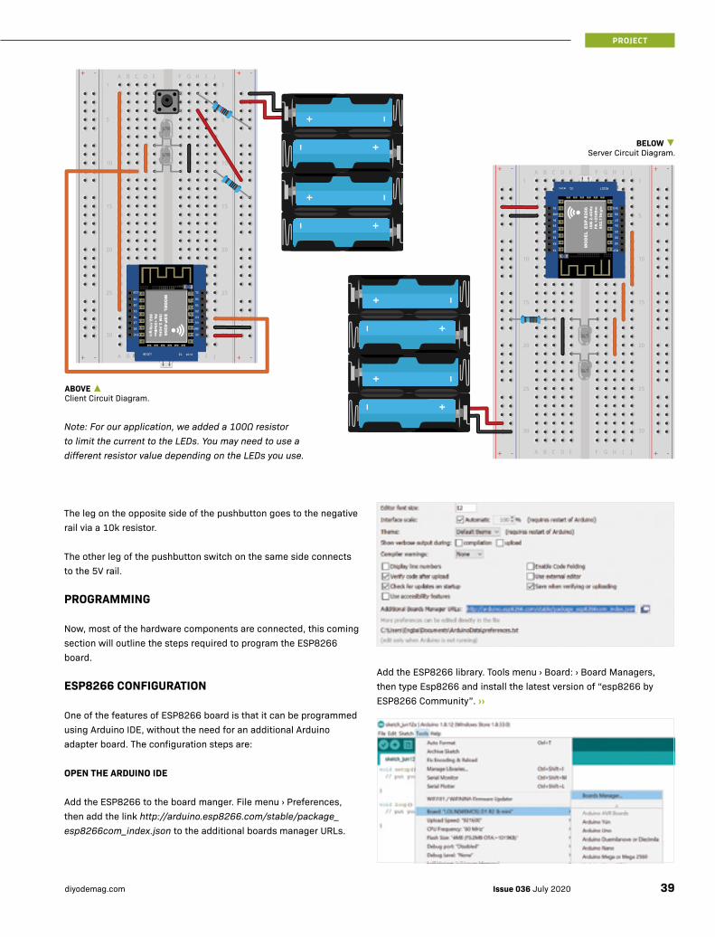
Add the ESP8266 library. Tools menu › Board: › Board Managers, then type Esp8266 and install the latest version of “esp8266 by ESP8266 Community”. ››
The leg on the opposite side of the pushbutton goes to the negative rail via a 10k resistor.
The other leg of the pushbutton switch on the same side connects to the 5V rail.
PROGRAMMING
Now, most of the hardware components are connected, this coming section will outline the steps required to program the ESP8266 board.
ESP8266 CONFIGURATION
One of the features of ESP8266 board is that it can be programmed using Arduino IDE, without the need for an additional Arduino adapter board. The configuration steps are:
OPEN THE ARDUINO IDE
Add the ESP8266 to the board manger. File menu › Preferences, then add the link http://arduino.esp8266.com/stable/package_esp8266com_index.json to the additional boards manager URLs.
Note: For our application, we added a 100Ω resistor to limit the current to the LEDs. You may need to use a different resistor value depending on the LEDs you use.
RST
A0
D0
D5
D6
D7
D8
3V3
TX
RX
D1
D2
D3
D4
GND
5V
RESETD1mini
RST
A0
D0
D5
D6
D7
D8
3V3
TX
RX
D1
D2
D3
D4
GND
5V
RESET D1 mini
ABOVE ▲Client Circuit Diagram.
BELOW ▼Server Circuit Diagram.
39Issue 036 July 2020diyodemag.com
PROJECT
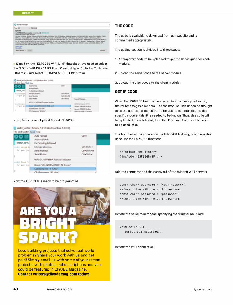
››Based on the “ESP8266 WiFi Mini” datasheet, we need to select the “LOLIN(WEMOS) D1 R2 & mini” model type. Go to the Tools menu › Boards: › and select LOLIN(WEMOS) D1 R2 & mini.
Next, Tools menu › Upload Speed › 115200
Now the ESP8266 is ready to be programmed.
THE CODE
The code is available to download from our website and is commented appropriately.
The coding section is divided into three steps:
1. A temporary code to be uploaded to get the IP assigned for each module.
2. Upload the server code to the server module.
3. Upload the client code to the client module.
GET IP CODE
When the ESP8266 board is connected to an access point router, the router assigns a random IP to the module. This IP can be thought of as the address of the board. To be able to communicate to this specific module, this IP is needed to be known. Thus, this code will be uploaded to each board, then the IP of each board will be saved to be used later.
The first part of the code adds the ESP8266.h library, which enables us to use the ESP8266 functions.
Add the username and the password of the existing WiFi network.
Initiate the serial monitor and specifying the transfer baud rate.
Initiate the WiFi connection.
//Include the library
#include <ESP8266WiFi.h>
const char* username = “your_network”;
//Insert the WiFi network username
const char* password = “password”;
//Insert the WiFi network password
void setup() {
Serial.begin(115200);
ARE YOU A BRIGHT SPARK?Love building projects that solve real-world problems? Share your work with us and get paid! Simply email us with some of your recent projects, with photos and descriptions and you could be featured in DIYODE Magazine. Contact [email protected] today!
Issue 036 July 2020 diyodemag.com40
PROJECT
These two IPs will be inserted later in the server and client code to enable them to communicate with each other.
SERVER CODE
This code will be uploaded to the ESP8266 board that will perform as a server. Similar to the previous code, there are some variables that will need to be inserted. Those variables are the username, password and the IP of the client board (obtained after uploading the previous code to it).
Firstly, the library that enables the ESP8266 functions to be employed is added to the Arduino sketch.
Next, the variables that are to be used are identified. Also, a number that is to be assigned to the port to transfer the data is identified. This number can be anything (we chose 80).
Add the username and the password of the existing WiFi network.
Initiate the serial monitor and set the baud rate to 115200. ››
//Include the library
#include <ESP8266WiFi.h>
int led = D5;
const char * host = “192.168.1.106”;
const char* Commands_Reply;
WiFiServer server(80);
const char* username = “your_network”;
const char* password = “password”;
void setup() {
Serial.begin(115200);
Print the IP of the ESP8266 board on the serial monitor
Connect the module to the computer through the USB cable.
From Tools menu › Port: › COM13.
Note: The port number will change depending on the port the board is connected to. In our case, it is port COM13.
Upload the code twice (for each ESP8266 board).
Open the serial monitor and save the IP somewhere.
Serial.print(“Attempting to connect to SSID”);
WiFi.begin(username, password);
while (WiFi.status() != WL_CONNECTED) {
Serial.print(“.”);
delay(1000);
}
Serial.println(“”);
Serial.println(“WiFi connected”);
Serial.println(“IP address: “);
Serial.println(WiFi.localIP());
}
41Issue 036 July 2020diyodemag.com
PROJECT

››Connect to the WiFi and print the local IP of the board (it should be the same as the one obtained from uploading the “Get IP” code).
Start the server.
Check if the client is connected to the server.
Check if the client has sent any data.
Read the data received from the client and clear the buffer.
Serial.println(“”);
Serial.println
(“Server------------------------”);
Serial.print(“Configuring access point”);
Serial.print
(“Attempting to connect to Network”);
WiFi.begin(username, password);
while (WiFi.status() != WL_CONNECTED) {
Serial.print(“.”);
delay(1000);
}
Serial.println(“”);
Serial.println(“WiFi connected”);
Serial.println(“IP address: “);
Serial.println(WiFi.localIP());
server.begin();
Serial.println(“Server started”);
WiFiClient client = server.available();
if (!client) {
return;
}
Serial.println(“Server-----------------”);
Serial.println(“New client”);
Serial.print(“From client = “);
while(!client.available()){
delay(1);
}
String req = client.readStringUntil(‘\r’);
Serial.println(req);
client.flush();
This part of the code, the server receives the data from the client to turn the LED ON or OFF and accordingly.
UPLOAD THE CODE
Connect the module to the computer through the USB cable.
Tools menu › Port: › COM13.
Note: The port number will change depending on the port the board is connected to. In our case, it is port COM13.
Upload the code to the server ESP8266 board.
Disconnect the board from the computer.
Now we have the code uploaded to the server board, the same steps will be repeated for the client (yet, obviously, with different code).
CLIENT CODE
This section will outline the various sections of the server code.
The IP address that will be inserted here is the IP of the server.
if (req.indexOf(“LED_On”) != -1){
Commands_Reply = “LED Status : On”;
Serial.print(“Server send = “);
Serial.println(Commands_Reply);
client.print(String(“GET “)
+ Commands_Reply + “ HTTP/1.1\r\n” + “Host: “
+ host + “\r\n” + “Connection: close\r\n\r\n”);
digitalWrite(led, HIGH);
}
else if (req.indexOf(“LED_Off”) != -1){
Commands_Reply = “LED Status : Off”;
Serial.print(“Server send = “);
Serial.println(Commands_Reply);
client.print(String(“GET “)
+ Commands_Reply + “ HTTP/1.1\r\n” + “Host: “
+ host + “\r\n” + “Connection: close\r\n\r\n”);
digitalWrite(led, LOW);
}
else {
Serial.println(“invalid request”);
client.stop();
return;
}
client.flush();
Serial.println(“Client disonnected”);
Serial.println
(“-------------------------------------”);
Serial.println(“”);
Issue 036 July 2020 diyodemag.com42
PROJECT

This part of the code handles the communication and sends the data to the server, establishing a connection with the server using the port number and IP...
...sending the commands to the server.
Check if the communication is established and whether there is a replay from the server.
UPLOAD THE CODE
Connect the module to the computer through the USB cable.
From Tools menu › Port: › COM13.
Note: The port number will change depending on the port the board is connected to. In our case, it is port COM13.
Upload the code to the client ESP8266 board.
Disconnect the board from the computer.
Now we have the code uploaded to the client board. ››
WiFiClient client;
if (!client.connect(host, httpPort)) {
Serial.println(“Connection failed”);
return;
}
client.print(String(“GET “) + Commands + “
HTTP/1.1\r\n” + “Host: “ + host + “\r\n” + “Con-
nection: Close\r\n\r\n”);
unsigned long timeout = millis();
while (client.available() == 0) {
if (millis() - timeout › 5000) {
Serial.println(“>>> Client Timeout !”);
client.stop();
return;
}
}
Serial.print(“Server Reply = “);
while(client.available()){
String line = client.readStringUn-
til(‘\r’);
Serial.print(line);
}
This loop is to detect if the push button is pressed, save the number of presses and reset the counter if the number of presses is more than two. This allows the program to have the capability to determine whether to turn the LEDs ON (e.g. one press) or OFF (e.g. second press).
This part of the code turns the LED on and off, and sends the data to the server according to the number of presses.
const char * host = “the_IP_address”;
const int httpPort = 80;
const char* Commands;
int LED = D3;
int button = D5;
bool btn_press = true;
int con = 0;
if (digitalRead(button) == LOW) {
Serial.println(“Client------------------”);
Serial.print(“Send Command = “);
if (btn_press == true){
if (con >= 2) {
con=0;
}
con++;
switch (con){
case 1:
digitalWrite(LED,HIGH);
Commands=”LED_On”;
Serial.println(Commands);
send_commands();
break;
case 2:
digitalWrite(LED,LOW);
Commands=”LED_Off”;
Serial.println(Commands);
send_commands();
break;
}
btn_press = false;
}
}
else {
btn_press = true;
}
delay(100);
}
43Issue 036 July 2020diyodemag.com
PROJECT

››TESTING
At this point, we have both of the circuits ready i.e. the server and the client, wired and programmed.
After we disconnect the modules from the computer, they will need a source of power to work on their own, and hence, are connected to their respective 6V battery holders. The positive of the battery is connected to the 5V pin, and the negative is connected to the GND pin.
Note: It is recommended not to exceed 7V due to the ratings of the voltage regulator on-board the ESP8266 module.
Now we have the completed project which operates such that:
• Pressing the push button connected to the client will turn the LED ON connected to it.
• Then the client module will send an “LED_ON” message to the server module through the WiFi network using the unique IP assigned to the server.
• The server receives the message and then, triggered by its program, turn its LED ON.
• By pressing the push button again, through the same mechanism, the program will count a repeated press, and turn both LEDs OFF.
Note: Due to the time required to both send and receive signals using the ESP8266 modules, there may be a small lag in communication.
ENCLOSURE
Finally, an enclosure was designed to both encase the server and client modules, as well as add the aesthetics of an “ON AIR” sign that is lit by the circuits’ LEDs. The enclosure was designed using TinkerCAD, a free, web-browser based program that is easy to use without the need for much CAD (computer assisted design) experience. For the design to meet our criteria, the “ON AIR” sign was printed using transparent filament to enable the LED light to pass through the enclosure.
WHERE TO FROM HERE?
A few examples of how this project may be scaled include:
• The addition of more client nodes that enables even more “ON AIR” lights to be positioned around the studio
• The replacement of the hardware trigger (e.g. pushbutton) with a software trigger (e.g. a graphical user interface on a web server) whereby these circuits may be triggered through any device that may access the WiFi network (e.g. computer, tablet, mobile phone, etc.)
• Through port forwarding, the ESP8266 module may be configured to allow this system to be triggered from anywhere in the world through the internet.
• Use a more powerful battery (Li-ion or Lead Acid) to control an LED Strip or something more "visible".
• To add additional artistic flair, or to customise the mounting or aesthetics of the “ON AIR” 3D printed sign (TinkerCAD working files will be included on our website for you to download)
Note: TinkerCAD can be downloaded for free at www.tinkercad.com. You will also find useful training guides on Fraser's website www.integratedstem.com.au
Whilst this project was focused on the design of an “ON AIR” sign for our recording studio, the ESP8266 module has almost limitless potential for makers looking to create a convenient, wireless control method for their own IoT (Internet-of-Things) projects.
Any of the client nodes created may trigger a circuit alternative to the LED circuit used in this project. For example, a simple relay circuit could be triggered by the client to turn on any household device (stick to low voltage only for the sake of safety i.e. below 50V). The possibilities of this module are limited only to your imagination – get out there and experiment with IoT for yourself! ■
WANT MORE?For the code and 3D print files, or to discuss this project, visit:https://diyode.io/036brgb
Issue 036 July 2020 diyodemag.com44
PROJECT

Free delivery on online orders over $99* *Exclusions apply - see website for full T&Cs.Shop the catalogue online! www.jaycar.com.au 1800 022 888
Hardcore electronics by
On sale 24 June 2020 to
23 July 2020
*Arduino®️ UNO compatible board
(XC4410 $29.95 sold separately)
Winter ProjectsYou'll save with Jaycar's great everyday value prices!
ONLY
$169
ONLY
$199
ONLY
$149
ONLY
$4995
ONLY$1895
ONLY
$2795
ONLY
$549 FINDER LITE 3D PRINTERThe easiest of all printers to use, the Finder Lite is supplied fully assembled. Featuring a very clean design with cables concealed from sight within the plastic alloy frame. All the heated components are kept away from touch. Low noise operation of 50dB or even less. Featured with a 3.5" touch panel, SD card slot, and more. • Prints up to 140x140x140mm TL4222
3D PRINTING PENCreate amazing 3D artwork. Mobile and lightweight. Includes power adaptor, stand and 3 x 10m filaments. Ages 14+.• Comfortable to hold• 1.75mm PLA / ABS
filament compatible TL4253
ARDUINO® STARTER KITThis official kit from Arduino® includes all the essentials to get you started in the exciting world of Arduino®️. Kit includes UNO board, breadboard and plenty of prototyping accessories. Perfect gift for a young electronics enthusiast or maker in the making. XC9200 See website for details
20MHZ USB OSCILLOSCOPE• Ultra portable • USB interface plug & play• Automatic setup• Waveforms can be
exported as Excel/Word files
• Spectrum analyser (FFT)• Includes 2 probesQC1929
INSPECTION CAMERA WITH 2.4" LCDExcellent for inspecting or locating objects in tight spaces.• Forward facing controls• Gooseneck: 1m long• Adjustable brightness LED
illuminator• Adjustable LCD brightnessQC8710
73 PCE MULTIFUNCTIONAL SCREWDRIVER SET A must-have kit for any technician or serious hobbyist with over 70 bit attachments to open all kinds of electronic devices. • Durable steel bits• Storage caseTD2136 See website for more details.
HEART RATE SENSOR MODULE KITMake your own health and fitness monitoring project with this heart rate monitor sensor kit. Includes the heartbeat sensor board, 3 x adhesive ECG pads and a colour-coded connecting cable. XC3784ALSO AVAILABLE: Spare ECG Pads 12pk XC3785 $8.95
IR DISTANCE SENSOR MODULE & CABLEUse this long-range infrared distance sensor to detect objects up to 1.5m away. 200mm long cable included.• Analogue output• 5ms maximum delay between
sample reading and output
XC3735
• ASSISTED LEVELLING SYSTEM• SINGLE NON-TOXIC PLA• 3.5-INCH TOUCHSCREEN PANEL
10PCE FILAMENT PACK 1.75mm PLA. To suit the TL4253 3D Printing Pen. Convenient 3m lengths. TL4255
ONLY
$7995ONLY$1495
4x4x4 KIT & Arduino® Compatible UNO!KM1097 + XC4410Total Value $49.90
BOTH FOR$3990
SAVE $10
ONLY
$1995AS SEEN IN
ISSUE 34 (MAY 2020)
4 X 4 X 4 BLUE LED CUBE KITBuild and marvel at your own programmable LED cube. This kit turns 64 blue LEDs, circuit board, a handful of components, and an Arduino®️ UNO compatible board* (XC4410) into an animated 4x4x4 LED cube. Soldering required.• Code your own animation sequences • Can program each LED individually• 65(W) x 88(H) x 65(D)mmKM1097 Components may differ slightly to the one shown

46 click & collect Buy online & collect in store ON SALE 24.06.2020 - 23.07.2020
Workshop Tools
• WI-FI, USB & ETHERNET CONNECT• AUTOMATIC FILAMENT FEEDING
ADVENTURER 3 Control print jobs via the cloud using FlashCloud and/or Polar Cloud. Small but compact structure with no angular design. Ready to use and no levelling printing. Removable, heatable and bendable plate. Built-in camera function. • 2.8" touchscreen panel• Prints up to 150(L) x150(W) x150(H)mmTL4256
DESKTOP 3D SCANNER V2 WITH SOFTWAREWatch real life objects become digitized before your eyes. Scans up to 250 x 180mm. Sleek, foldable design for workspace storage. Comes packed with MFStudio software with +Quickscan. • Scans up to 250(H) x 180(D)mmTL4420See website for details.
• 4.3" COLOUR TOUCH SCREEN
• SILICON PRINTING PLATFORM
ONLY
$1499FROM
$2495ONLY
$4495
ONLY
$1299ONLY
$8993D PRINTING WITH AUTODESK 123D, TINKERCAD AND MAKERBOT - BOOKThis book will guide you to how to operate powerful, free software from Autodesk and bring your creations to life. Fun projects, easy-to-follow instructions, and clear screenshots.BM7122
1.75MM PLA FILAMENTThe best, most consistent and most tested PLA filament engineered and manufactured by FlashForge. Various colours available. 600g TL4260 - TL4266 $24.951kg TL4270 - TL4276 $39.95See in-store or online for full range.
• SOFT COVER• 302 PAGES
TL4260
TL4262
TL4273
YOUR DESTINATION FOR 3D PRINTING. Think. Possible.
DUAL FILAMENT Allows you to combine colours and materials creating high-quality prints. Oversized bed screws for leveling the print bed. Dual cooling fans. SD memory card slot. • Prints up to 300(L) ×
300(W) × 400(H)mmTL4410 Limited stock. Check store for stock availability.
DUAL COLOUR PRINTING
JUST$1350
JUST$495
JUST$4495
JUST$1395
JUST$1395
JUST$3495
JUST$1595
JUST$795
JUST$995
10 PCE NEEDLE FILE KITAll have integrated plastic handles and come in a handy storage wallet.• Each is 162mm longTD2128
JUST$1795
PIN VICE Metal construction with two internal collars. The head rotates freely making it ideal for drilling delicate PCB's. TH1772
ARTWORK KNIFE Light duty with safety cap. Ideal for fine angle cuts, etching, hollowing, scoring, scraping, scribing, stripping and trimming. HG9955
4 PCE MINI PICK & HOOK SETIdeal for use on O-rings, springs, snap rings, washers, checking soldering joints, etc. Stainless steel heat treated points. TH1762
SOLDERING HEATSINK / COMPONENT HOLDERInsulated handles. 65mm long. TD2122
OPENER TOOL FOR CURVED SCREENSQuickly remove a curved LCD screen from the devices frame. 0.1mm Thickness. Super tough steel. TD2138
150MM - CARBON STEEL PRECISION SIDE CUTTERS • Designed for sharp cutting
in precision wiring• Insulated soft-touch handleTH1891
115MM - STAINLESS STEEL SIDE CUTTERS Thick (2mm) blades with soft plastic handles.TH1890
125MM - CARBON STEEL PRECISION LONG NOSE PLIERS Features serrated jaws and a box joint to provide a precise action and strong grip. • Insulated soft-touch handleTH1885
145MM - STAINLESS STEEL LONG NOSE PLIERS Perfect for adjusting and bending components. Soft plastic handles.TH1893
TECH TALK:
Stainless vs CarbonFor those who have only occasional use for hand tools, we recommend stainless steel products, however, keep in mind that Carbon steel is far harder and tougher than stainless. The problem, of course, is that carbon steel will rust if not maintained, but like carbon steel knives, rust is not a problem if used constantly.
DOZENS OF FILAMENT COLOURS & TYPES
AVAILABLE FROM $24.95

47In the Trade?
YOUR DESTINATION FOR WORKBENCH ESSENTIALS. Think. Possible.
JUST
$2995JUST
$2495
JUST
$119JUST
$1995
LED ILLUMINATED CLAMP MOUNT MAGNIFIER • Powerful 125mm
diameter 3 dioptre lens• Fully adjustable arm
with clamp mount • Interchangeable lens optionQM3554ALSO AVAILABLE:Rolling Floor Base QM3549 $99.95
PORTABLE STORAGE BOX WITH 3 DRAWERS Carry your electronic components, parts, hardware and crafting accessories,• 3 Drawers with dividers• Safety lockHB6334
SILICONE BENCHTOP WORK MAT • Heat resistant • Suitable for soldering applications• Magnetic areas to hold metal parts• 389 x 269mm work areaHM8102
Soldering StationsSoldering stations allow temperature adjustment by regulating
the power supplied to the heating element. Analogue units are the simpler variety, often incorporating a variable power
control (similar to a light dimmer) to select the temperature, and a thermostat to keep it constant. Digital stations offer greater
precision thanks to microprocessor control, and include an LED readout showing the tip temperature. Advanced stations include
a hot air gun for SMD rework.
Don't forget your solder & flux!
SOLDER FLUX PASTE
Provide superior fluxing and reduce solder waste.
Non-flammable, non-corrosive. 56g tub. NS3070
200GM DURATECH SOLDER 60% Tin / 40% Lead. Resin cored. 2 sizes available.1.00mm NS30100.71mm NS3005
JUST$1795
ONLY$1695
EA
TS1564 TS1640 TS1648 TS1440
Station Type Soldering Soldering Soldering & Hot Air Soldering
Display Analogue Digital LED LED
Power (W) 48W 60W 300W rework, 60W solder 65W
Temperature Range 150°C to 450°C 160°C to 480°C 50°C to 480°C 200°C to 480°C
Weight 2kg 1.5kg 6kg 1.5kg
QUALITY TEMPERATURE PROBE & CARRY CASE INCLUDED.
600A TRUE RMS AC • Cat III, 4000 display count• AC/DC Voltage: 600V/600V• AC Current: 600AQM1630 See website for details.
Our range of CAT III Clamp Meters makes the best general troubleshooting tool for commercial and residential electricians and includes features found
on more expensive units such as autoranging, data hold, non-contact voltage, relative measurement and auto power-off. Multi function with Resistance, Capacitance, Frequency and Temperature.
600A TRUE RMS AC/DC • Cat III, 4000 display count• AC/DC Voltage: 600V/600V• AC/DC Current: 600A/600AQM1632See website for details.
1000A TRUE RMS AC/DC • Cat III, 6000 display count• AC/DC Voltage: 750V/1000V• AC/DC Current: 1000A/1000AQM1634See website for details.
JUST
$5995
ONLY
$8995
ONLY
$129
NS3010
NS3005
• LARGE DIAMETER MAGNIFIER
• HIGH / LOW LIGHT SETTING
DURABLEPCB HOLDER WITH MAGNIFIER• Perfect for PCB assembly &
soldering• 2X magnifying lens• Requires 3 x
AAA batteries (SB2413 $3.25 sold separately)
TH1987
TS1564 WAS $119$109
SAVE $10
TS1648 WAS $249$229
SAVE $20
TS1440 WAS $329$299
SAVE $30
TS1640 WAS $159$139
SAVE $20

48 click & collect Buy online & collect in store ON SALE 24.06.2020 - 23.07.2020
YOUR DESTINATION FOR NETWORKING PROJECTS. Think. Possible.
DVI-D TO DVI-D VIDEO CABLEMale to male. 24pin. 2m long. WC7590
JUST$1095
JUST$2195
ONLY$2995
FROM
$2795FROM
$3495ONLY
$4995
D9 MALE TO D9 FEMALE EXTENSION CABLEAll pins wired straight through. 1.8m long. WC7534
USB 3.1 TYPE-C CONVERTERSUse to take advantage of high performance USB Type-C connectors on new PCs, Macs®️ and Chromebooks to convert to an existing VGA or HDMI signal.To VGA Signal XC4931 $34.95To HDMI Signal XC4933 $49.95 (Shown)
XVGA MONITOR CONNECTING CABLEDB15HD male to DB15HD male. 2.0m long. WC7586
RS-232 DB9M TO USB CONVERTERSConnect a variety of RS-232 devices to your modern computer with these adaptors.To USB Adaptor XC4927 $27.95 (Shown)To USB 1.5m Lead XC4834 $29.95
USB PORT TO RS-485/422 CONVERTERUp to 480Mbps data transmission. Automatically detects serial signal rate. XC4136
NEED A PC LEAD? WE STOCK A HUGE RANGE OF
COMPUTER LEADS. LISTED BELOW ARE JUST SOME OF THE MOST
POPULAR ONES. See website or instore for full range.
AC1900 DUAL BAND USB 3.0 WI-FI ADAPTORDual Band USB 3.0 adaptor connects your laptop/PC wirelessly to the next generation 802.11ac technique with max speeds of 1900Mbps. YN8337
SOLID NETWORK CABLESUsed for long runs in permanent installations. ACA approved. CAT5E 100M ROLL WB2022 $1.20/m 30M POLYWRAP WB2023 $29.95 CAT6100M ROLL WB2030 $1.45/m
TRI-BAND WI-FI ROUTER WITH 4 X RJ45 GIGABIT LAN PORTSDelivers a massive combined wireless speed of up to 3000Mbps. TouchLink technology to connect to Wi-Fi with a simple touch of the router.• 400Mbps in 2.4GHz + 867Mbps in
5GHz + 1733Mbps in 5GHz) • 802.11/a/b/g/n/ac Standards YN8396
ONLY $1495
ONLY $895
ONLY
$9995
ONLY
$229
FROM
$4995JUST
$99ONLY
$2995
RJ45 MODULAR PLUGSPacket of 10 RJ45 plugs for stranded and solid CAT6 cable. PP1447
FROM$120
/m
CAT-5 PUNCH-DOWN TOOL & STRIPPERStrip wire up to 5-6mm, and doubles as a punch-down tool for 110/88-type terminals with blade. TH1738
2 BAY USB 3.0 SATA HDD RAID ENCLOSUREHave your files backed up. Tool less & driverless. Supports 2.5” and 3.5” HDD.• Raid 0, Raid 1, JBOD, Spanning• Up to 5Gbps transfre rate• Capacity: 8TB Per Bay• 215(L) × 135(W) × 114(H)mmXC4688
2.5" USB 3.0 HDD ADAPTOR WITH CASEConnect a 2.5" SATA 6G hard drive to your computer with transfer speeds up to 5Gbps. USB powered. XC4152
USB 3.0 SATA HDD DOCKING STATIONSConnect 2.5” or 3.5” SATA hard drives to your computer. Plug and play technology. USB 3.0 for fast data transfer.• Transfer Rate: 430Mbps• HDD capacity: 8TBSingle XC4687 $49.95 (Shown)Dual XC4689 $64.95
XC4927
XC4933
XC46
87• AUTOMATIC
CONNECTION DETECTION
• PLUG AND PLAY• TURBO BUTTON TO
OPTIMISE YOUR NETWORK
8 HIGH-PERFORMANCE ANTENNAS DELIVER UNSURPASSABLE WI-FI COVERAGE
COMPACT
YN8395
ULTRA-FAST GIGABIT ETHERNET SWITCHESProvide additional ports to an internet router, firewall, or a standalone network. Backward compatible with 10/100 interfaces.• 10/100/1000Mbps RJ45 Port• Automatic connection detection5 Port YN8395 $39.95 (Shown)8 Port YN8397 $59.95
USB 3.0 ETHERNET CONVERTERConnect an Ethernet cable to an existing USB port. Perfect for Apple®️ MacBook®️ and Ultrabooks™. YN8418
FROM
$3995
JUST
$3995Make your own network cables
Manage your data

49More ways to pay:
Multi State Battery Chargers
All-in-one chargers which have multiple charge settings to suit different sized batteries and charging requirements. Capable of recharging the battery and maintaining the charge state indefinitely, they are particularly well suited to being continuously connected to a battery. Choose between mains powered chargers for workshop use and DC-DC models for in-vehicle or marine use. See website for full details.
SEE IN-STORE OR ONLINE FOR OUR FULL RANGE OF SLA BATTERIES.
YOUR DESTINATION FOR ON THE GO CHARGING. Think. Possible.
ONLY $995
FROM $1995
ONLY
$3995
ONLY
$7995FROM
$129
ONLY
$4695
MB3940ONLY
$219
LEAD ACID BATTERY CONDITIONERRemoves or reduces sulphation which kills batteries. One bottle will do up to a N7OZ size battery (4WD, boat, truck, etc.)NA1420
DUAL-CHANNEL LI-ION / NI-MH BATTERY CHARGERCharges Li-ion, LiFePO4, Ni-Cd, Ni-MH from AAA to D sizes. Supplied with USB and in-car cigarette lighter power leads. MB3635
12VDC LEAD ACID BATTERY TESTERQuickly, easily, and accurately measures the cold cranking amps capability of the vehicle starting battery. • Voltage Measure Range:
6-30VDCQP2261
BATTERY ISOLATION SWITCHES High current rated battery isolation switches for high power applications. They feature high quality construction with huge bolt down terminals for electrical connection.12V 120A SF2245 $19.95 (Shown)12V 500A SF2247 $69.95
HIGH CAPACITY ENELOOP PRO NI-MH BATTERIESCan be recharged 500 times, and will retain up to 85% of their capacity after a year in storage. Pre-charged.900MAH AAA PK4 SB29382450MAH AA PK4 SB2936ALSO AVAILABLE:Eneloop Charger MB3563 $49.95
BATTERY DISCHARGE PROTECTOR Protects your vehicle battery by switching off appliances before the battery voltage drops to an unrecoverable level. • Operating voltage: 12VDC• Max. switching current: 20A• Interrupting voltage: 10.4 - 13.3VDCAA0262
DEEP CYCLE SLA BATTERIES Excellent for high capacity versatile storage. Leakproof and completely sealed, ideal for solar power, 4WD, camping etc. 12V 26Ah SB1698 $12912V 38Ah SB1699 $19912V 100Ah SB1695 $379* (Shown)*Limited stock. Check store for stock availability.
SB29
36
SB1695
SF22
45
• FOR USE IN VEHICLES • DUAL INPUT: SOLAR AND/OR
ALTERNATOR/CAR BATTERY
LI-ION RECHARGEABLE BATTERIESA range of nipple cap and solder tab batteries in varying capacities.SB2300-SB2319See website for full range.
AA BATTERY HOLDERS2 x AA Side by Side PH9202 $1.452 x AA Switched Battery Enclosure PH9280 $3.95See website for full range.ALSO STOCK HOLDERS FOR 18650 (ETC.) CELLS
FROM
$1095FROM
$145PH9202
ONLY
$3295EA
Battery management & protection
MB3902 NEW MB3611 MB3621 MB3940 NEWOutput Voltage(s) 6/12VDC 6/12VDC 12VDC 12VDC
Max Output Current 870mA 1A/4A 30A 20A
Multi Stage 7 4 5 6
Battery SupportSealed, Gel, AGM or Flooded Lead (6/12V, 1.2Ah-26Ah), LiFePO4 (12.8V, 2Ah-15Ah)
Wet, Gel cell, AGM and LiFePO4 (5Ah-120Ah)
Lead acid, AGM and LiFePO4 (50Ah-300Ah)
Lead acid, AGM, Calcium, GEL or LiFePO4 batteries (50Ah to 300Ah)
Type Mains Powered Mains Powered Mains Powered DC-DC
Special Features IP65 Dust and weatherproof rated.
IP65 Dust and weatherproof rated, LCD display.
IP65 Dust and weatherproof rated. Intelligent charger can operate with or without load.
IP65 Dust and weatherproof rated. Dual input: solar and/or alternator/car battery.
MB3902ONLY $2995
MB3611ONLY $9995
MB3621ONLY
$369
SB23
08
SB2301

YOUR DESTINATION FOR DIY & RASPBERRY PI PROJECTS. Think. Possible. MAKING RASPBERRY PI PROJECTS POSSIBLE
Whether you’re just starting with Raspberry Pi for the first time, or you want to expand upon a Raspberry Pi project, we
have an extensive range of accessories to make that possible.
RETRO ARCADE GAME CONSOLES FOR RASPBERRY PILet the games begin with these exciting retro arcade consoles. Simply install a Raspberry Pi 3B+ (XC9001 $89.95 Sold Separately), into the console, insert a Retropie installed micro SD card (XC9031 $24.95 Sold Separately), copy over some games and you are ready to play. See website for detailed install instructions.10" SCREEN RETRO ARCADE GAME CONSOLE• Includes a joystick
and 6 buttons.• Built-in speakerXC9064 $249RETRO ARCADE GAME CONSOLE• Connects to your TV, computer or
projector with HDMI or VGA cable• 2 Player consoleXC9062 $169
ONLY
$249XC9064
ONLY$995RETRO NES STYLE CONTROLLERSNES layout. Features A/B/X/Y buttons, start, select, and direction controls. Easily configurable, USB powered. XC4404
STANDARD LEDSAvailable in 3 different sizes & colours. Waterclear lens. 100mA.
ONLY
$3995
ONLY
$1095
JUST
$395
ONLY
$3995FROM
$395
RETRO NES CASEPerfect for building a Raspberry Pi 3/3B+ based emulator.• HDMI, 3.5mm, and
micro USB (power) access
• USB Ports: 4 (Standard, Type –A)
XC4403
RETROPIE OS ON 16GB SD CARD FOR RASPBERRY PIPreloaded with RetroPie, and auto-installs when used for first time. Supplied with an SD card adaptor XC9031Note: Best compatible for Raspberry 3B/3B+
ONLY
$2495RETRO GAMING WITH RASPBERRY PI BOOKThis book shows you how to set up your Raspberry Pi for retro gaming, learn to program retro-style games, build a portable console, arcade cabinet, pinball machine and more. 164 pages. BM7166
HEATSINK PIN GRID ARRAYAn aluminium heatsink with adhesive thermal transfer tape. Suitable for Rasberry Pi and other BGA devices. HH8581
19MM IP67 METAL PUSHBUTTON SWITCHESDurable and stylish stainless steel switch with LED illumination.• 12V LED Illumination• DPDT Momentary action• Spade or solder connectionRed DPDT SP0800 $19.95Blue DPDT SP0802 $19.95Green DPDT SP0804 $19.95Blue SPDT SP0810 $20.95
LIGHT DUTY HOOK-UP WIRE PACK Quality 13 x 0.12mm tinned hook-up wire on plastic spools. 8 rolls of different colour included. 25m on each roll. WH3009
THE CHAMP 0.5W AUDIO AMPLIFIER KITUses the LM386 audio IC, and will deliver 0.5W into 8 ohms from a 9V supply making it ideal for all those basic audio projects. PCB and electronic components included. • 46(L) x 26(W)mmKC5152
GREY VENTED ABS ENCLOSURES Protect your project from unwanted fingers or objects.• Satin textured finish• Moulded standoffs• Snap-fit assembly40 x 40 x 20mm HB6114 $3.9560 x 60 x 20mm HB6116 $5.4580 x 80 x 20mm HB6118 $5.95
ONLY
$3495
TECH TALK:
Light Emitting Diodes• Luminous intensity (IV) does not represent total light
output from an LED. Both the luminous intensity & the spatial radiation pattern (viewing angle) must be taken into account
• If two LEDs have the same luminous intensity value, the lamp with the larger viewing angle will have the higher total light output
3mm Green ZD0125Blue ZD0134White ZD0144
5mm Green ZD0177Blue ZD0183White ZD0196
10mmGreen ZD0208
FROM
$225
DIGITAL MULTIMETER KITLearn everything about component recognition and basic electronics with this comprehensive kit. Kit includes DMM case, LCD, solder, battery, test leads, PCB, comprehensive 18 page manual and components. • 67(W) x 123(H) x 25(D)mmKG9250
FROM$1995
SINGLE BOARD COMPUTER
RASPBERRY PI 3B+ Tiny credit card size computer. • 1.4GHz 64-bit quad-core processor• Dual Band 2.4GHz & 5GHz
Wireless LAN• Bluetooth®️ 4.2 technology
with BLE • Faster processing and networking• Supports Power-over-Ethernet (with
separate PoE HAT)XC9001
JUST
$8995
ALSO AVAILABLE:Raspberry Pi Beginners Guide Book 2nd Edition BM7164 $27.95
Looking for other projects to do?
ONLY
$2495
TRI-COLOUR LED5mm size. Red, green & blue. Waterclear lens. 100mA. ZD0269
See our full range of Silicon Chip projects at:
jaycar.com.au/c/silicon-chip-kits
Or our kit back catalogue at: jaycar.com.au/kitbackcatalogue
XC9062ONLY
$169
50 click & collect Buy online & collect in store ON SALE 24.06.2020 - 23.07.2020

More ways to connect wirelessly
More shields & modules
PROJECT: Arduino® Keyboard Emulator
WITH FINGERPRINT LOGIN
MAKE YOUR PROJECTS: Wireless
MAKING ARDUINO PROJECTS POSSIBLE We carry an extensive range of Arduino-compatible
boards, modules, shields, and accessories to make your next Arduino-based project possible.
YOUR DESTINATION FOR ARDUINO. Think. Possible.
ESP32 MAIN BOARD WITH WI-FI & BLUETOOTH® COMMUNICATION Dual core microcontroller equipped with Wi-Fi and Bluetooth®️ connectivity. 512kB of RAM, 4MB of flash memory and heaps of IO pins. XC3800
YUN WI-FI SHIELD Allows you to easily program and operate your Arduino®️ project over Wi-Fi and allow it to access the Internet. Contains a tiny Linux computer with Wi-Fi, ethernet & USB. XC4388
UNO BOARD WITH WI-FI Includes a traditional Arduino®️ UNO chip & layout as well as an ESP8266 chip to connect your projects to the cloud without the need for additional modules. XC4411
MEGA BOARD WITH WI-FIAn Arduino® + Wi-Fi Dual board that includes a traditional Arduino chip + layout as well as an ESP8266 chip to connect your projects to the cloud. XC4421
ONLY
$3995ONLY
$3995
JUST
$5995
JUST
$1395EA
JUST$595
BLUETOOTH® V4.0 BLE MODULE Brings the latest Bluetooth®️ 4.0 standards to your Arduino®️ project. Configurable as master or slave. Provides a serial communication channel. Serial interface with AT commands. XC4382
RF TRANSCEIVER MODULE Adds a versatile 433MHz radio to your Arduino®️ project allowing two-way wireless communication between Arduinos. Includes antenna. • 1.9-3.6VDC operating voltage • Controlled via SPI.XC4522
JOYSTICK CONTROLLER Use a joystick to control your mouse. XC4422
Tired of entering your password each time you access your computer at home or work? Use our completely extensible fingerprint login system project. Using the Leonardo compatible board and our fingerprint sensor, you will be able to log in to your computer with only a thumbprint. Use the Fingerprint for secure features such as logging in, opening the browser, or reading your secret documents. What’s more, you can also add more modules such as joysticks or keypads to further extend your Arduino keyboard emulator system, right at your fingerprints!SKILL LEVEL: EasyTOOLS: Soldering IronWHAT YOU WILL NEED:1 x Leonardo R3 Development Board XC4430 $29.951 x Prototyping Board Shield XC4482 $15.951 x Fingerprint Sensor Module XC4636 $49.95
433MHZ WIRELESS MODULESPre-built 433MHz wireless transmitter / receiver modules. Feature ASK encoding.Ideal for devices using short data bursts such as remote controls, trigger pulses etc.Transmitter ZW3100 (Shown)Receiver ZW3102
FEEDBACK BUZZERAlert on password or thumbprint failure, to deter others trying to use your device. AB3459
2.4GHZ WIRELESS TRANSCEIVER MODULE Based on the NRF24L01 transceiver IC, this module allows communication on the license free ISM band. Supports on-air data rates of up to 2Mbps. XC4508
EXTENDED KEYPAD Add up to 16 macro buttons to assign to your computer once you have logged in. XC4602
INFRARED MODULES These modules allows you to send/receive data over infrared. Use the receiver (XC4427) to read signals sent by most IR remote controls, or pair with the transmitter (XC4426) to make a universal remote control.Transmitter XC4426 $4.95Receiver XC4427 $4.50
MINI REED SWITCH Lock your PC as soon as something is removed from your desk. LA5074
JUST
$2995
JUST
$1995FROM
$450ONLY
$995
ESP-13 WI-FI SHIELD Uses the powerful ESP8266 IC and has an 80MHz processor. An excellent way to get into the Internet of Things. Integrated TCP/IP stack. Simple AT command interface with Arduino main board. XC4614
ONLY
$3995ONLY
$6995ZW
3100
XC4426
XC4427
Upgrade Your Project!
JUST$495
JUST$995
JUST$750
SEE PARTS & STEP-BY-STEP INSTRUCTIONS AT: www.jaycar.com.au/fingerprint-loginSee other projects at www.jaycar.com.au/arduino
CLUB OFFERBUNDLE DEAL
$6995
KIT VALUED AT $95.85
SAVE 25%
51More ways to pay:

What’s5MP HIGH DEFINITION WEB CAMERAClear crisp 1080p HD video for Skype, Zoom, or other video conferencing applications.• FHD auto-focus for brighter pic• Auto-adjusts for crystal clear
image even in low light • Double mic stereo soundQC3207
16CH 4K NVR KIT WITH 8 X 4K PIR SPOT LIGHT BULLET + 4 X 4K PIR CAMERASProtect your property with this multi-camera, wired surveillance system with everything you need to do-it-yourself or have it professionally installed. High quality video allows you to see greater detail to positively identify security issues.• Up to 150 days recording with dropbox capability
to ensure important footage is available for review.• Swann’s True Detect™ heat & motion-based PIR
detection reliably captures & records activity• Records audio for additional layer of securityQV9099
ONLY
$2999
ONLY
$1395
DUINOTECH ATTINY85
MICRO USB DEVELOPMENT BOARDFeatures an ATtiny85 8-bit microcontroller that you can program using the Arduino IDE. 8k Flash Memory.• 6 x I/O connections• Integrated 5V RegulatorXC3940
DISPLAYPORT V1.4 LEADSUsed to connect a video source to a display device such as a computer monitor, TV or projector. Supports up to 8K@60Hz video resolution.Plug To Plug 1.8m WQ7460 $19.95Plug To Plug 3.0m WQ7462 $29.95Plug To Mini Plug 1.8m WQ7464 $29.95
EXTRA LONG TV COAX CABLESSuper flexible coax leads that makes it easier to run through entertainment cabinets and along skirting boards, etc.• Quality RG6 quad shielded coax cable• F-Plug to F-Plug10m WV7468 $24.9520m WV7470 $34.95
4G GPS VEHICLE TRACKERLocate and track the whereabouts of your vehicle in realtime via the Internet on a computer, Smartphone or Tablet.• SMS location & tracking return• Rechargeable battery• GPS & GSM module• Geo Fence Alarm4G Sim card needed, can be purchased separately from Telstra, Optus, etc.LA9038
5W GME UHF RADIO WITH BLUETOOTH®
COMMUNICATIONiOS and Android apps available to configure, update and customise the radio. 10-16VDC input.• 80 FM CB radio channels• 50 Ohm antenna impedance• Bluetooth®️ enabled allows
creating and sharing of lists. DC9059
FROM
$1995
ONLY
$229
ONLY
$549
FROM
$2495ONLY
$9995
View live footage on a Smartphone.
Smartphone not included.
ONLY
$129
12 CAMERA KIT
2TB HDD
• BUILT-IN MICROPHONE• ENGINE KILL FUNCTION
9-IN-1 MULTIFUNCTION TYPE-C USB HUBConnect just about anything to your Macbook®️ or latest laptop. Connections include an HDMI output with 4K support, an RJ45 Ethernet port for speeds up to 1000Mbps, SD and microSD memory card slots, 3.5mm stereo audio in and out, and 2 x USB3.0 hot-swap capable ports to connect computer peripherals, hard drives up to 1TB, etc. XC4975
RJ45 Ethernet - 1GBPS
SD & microSD Card
Type-C with Power Delivery
USB 3.0
2 x 3.5mm MIC & Headphone
4K HDMI OutputUSB 3.0
XRS-370C
TERMS AND CONDITIONS: REWARDS / CLUB MEMBERS FREE GIFT, % SAVING DEALS, & MEMBERS OFFERS requires ACTIVE Jaycar Rewards / membership at time of purchase. Refer to website for Rewards / membership T&Cs. IN-STORE ONLY refers to company owned stores and not available to Resellers. Page 1: Bundle Deal: 1 x KM1097 + 1 x XC4410 for $39.90. Page 7: Club Offer: Arduino Keyboard Emulator with Fingerprint Login project includes 1 x each of XC4430, XC4482, XC4636 for $69.95.
Arrival dates of new products in this flyer were confirmed at the time of print but delays sometimes occur. Please ring your local store to check stock details. Occasionally there are discontinued items advertised on a special / lower price in this promotional flyer that has limited to nil stock in certain stores, including Jaycar Authorised Resellers. These stores may not have stock of these items and can not order or transfer stock. Savings off Original RRP. Prices and special offers are valid from catalogue sale 24.06.2020 - 23.07.2020.
HEAD OFFICE320 Victoria Road, Rydalmere NSW 2116Ph: (02) 8832 3100Fax: (02) 8832 3169
ONLINE [email protected]
Over 100 stores & 130 resellers nationwide
For your nearest store & opening hours:
1800 022 888 www.jaycar.com.au
ELIZ
ABE
TH S
T
HORSLEY DR
HORSLEY DR
CANLEY VALE RD
OFFICEWORKS
GOODGUYS
BABYBUNTINGSUPERCHEAPAUTO
RAYWHITE
SERVICENSW
N
NEW STORE
Wetherill ParkShop 52, 1183-1187 The Horsley Drive
Wetherill Park, NSW(02) 9604 7411

SIMON SAYSHandheld Electronic Game using ArduinoWhen a maker wants to teach his 7 year old great-nephew electronics and have fun at the same time, he turns an old classic game into a handheld game for hours of fun.
Issue 036 July 2020diyodemag.com 53
FEATURE
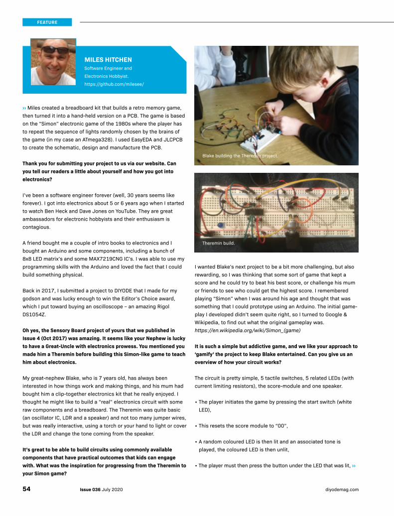
››Miles created a breadboard kit that builds a retro memory game, then turned it into a hand-held version on a PCB. The game is based on the “Simon” electronic game of the 1980s where the player has to repeat the sequence of lights randomly chosen by the brains of the game (in my case an ATmega328). I used EasyEDA and JLCPCB to create the schematic, design and manufacture the PCB.
Thank you for submitting your project to us via our website. Can you tell our readers a little about yourself and how you got into electronics?
I’ve been a software engineer forever (well, 30 years seems like forever). I got into electronics about 5 or 6 years ago when I started to watch Ben Heck and Dave Jones on YouTube. They are great ambassadors for electronic hobbyists and their enthusiasm is contagious.
A friend bought me a couple of intro books to electronics and I bought an Arduino and some components, including a bunch of 8x8 LED matrix’s and some MAX7219CNG IC’s. I was able to use my programming skills with the Arduino and loved the fact that I could build something physical.
Back in 2017, I submitted a project to DIYODE that I made for my godson and was lucky enough to win the Editor’s Choice award, which I put toward buying an oscilloscope – an amazing Rigol DS1054Z.
Oh yes, the Sensory Board project of yours that we published in Issue 4 (Oct 2017) was amazing. It seems like your Nephew is lucky to have a Great-Uncle with electronics prowess. You mentioned you made him a Theremin before building this Simon-like game to teach him about electronics.
My great-nephew Blake, who is 7 years old, has always been interested in how things work and making things, and his mum had bought him a clip-together electronics kit that he really enjoyed. I thought he might like to build a “real” electronics circuit with some raw components and a breadboard. The Theremin was quite basic (an oscillator IC, LDR and a speaker) and not too many jumper wires, but was really interactive, using a torch or your hand to light or cover the LDR and change the tone coming from the speaker.
It’s great to be able to build circuits using commonly available components that have practical outcomes that kids can engage with. What was the inspiration for progressing from the Theremin to your Simon game?
I wanted Blake’s next project to be a bit more challenging, but also rewarding, so I was thinking that some sort of game that kept a score and he could try to beat his best score, or challenge his mum or friends to see who could get the highest score. I remembered playing “Simon” when I was around his age and thought that was something that I could prototype using an Arduino. The initial game-play I developed didn’t seem quite right, so I turned to Google & Wikipedia, to find out what the original gameplay was. https://en.wikipedia.org/wiki/Simon_(game)
It is such a simple but addictive game, and we like your approach to ‘gamify’ the project to keep Blake entertained. Can you give us an overview of how your circuit works?
The circuit is pretty simple, 5 tactile switches, 5 related LEDs (with current limiting resistors), the score-module and one speaker.
• The player initiates the game by pressing the start switch (white LED),
• This resets the score module to “00”,
• A random coloured LED is then lit and an associated tone is played, the coloured LED is then unlit,
• The player must then press the button under the LED that was lit, ››
MILES HITCHENSoftware Engineer and
Electronics Hobbyist.
https://github.com/milesee/
Blake building the Theremin project.
Theremin build.
Issue 036 July 2020 diyodemag.com54
FEATURE
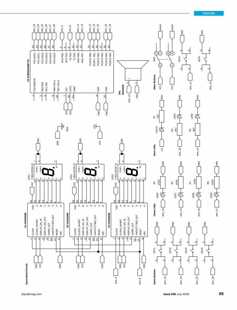
Othe
r But
tons
KEY5
213 4
KEY6
213 4
GND
GNDpo
wer
pow
er
3
21 6
54
SW1
atm
_14
atm
_13
VCC
VCC
SPEA
KER
SP1
2 1GN
D
atm
_12
3mm
LED
s
4k7
R4 4k7
R5
LED4
LED5
LED1
010
kR7
GND
GND
GND
atm
_24
atm
_18
vcc
GND
GND
GND
GND
10m
m L
EDs
100Ω
R1100Ω
R2100Ω
R3 100Ω
R6
LED6
LED7
LED8
LED9
atm
_27
atm
_26
atm
_23
atm
_16
Gam
e Bu
tton
sKE
Y13 4
KEY2
3 4
KEY3
3 4
KEY4
3 4
GND
GND
GND
GND
21 21 21 21
atm
_28
atm
_25
atm
_19
atm
_15
CLOC
K
CLOC
K_IN
HIB
IT
DISP
LAY_
EN_I
N
DISP
LAY_
EN_O
UT
CARR
Y_OU
T
F GVS
S
DA EB C
UNGT
D"C"
SEG_
OUT
RESE
T
VDD
7-SE
G-SC
39-1
2LE
D3
1 6
U3 C
D402
6BE
6 7910 1112 1316VC
C1 2 3 4 5 8
14 15
GND
VCC
GND
atm
_4
atm
_6F
25910 8 4
G3
DBACO
MC1
C E
COM
C2
7-SE
G-SC
39-1
2LE
D2
DP71 6
DP7
GND VC
C
GND
VCC
FDBACO
MC1
C E G
COM
C2
25910 8 4 3
VCC
U2 C
D402
6BE
F6
G7
D9
A10
E11
B12
C13
VDD
16CL
OCK
1
CLOC
K_IN
HIB
IT2
DISP
LAY_
EN_I
N3
DISP
LAY_
EN_O
UT4
CARR
Y_OU
T5
VSS
8
UNGT
D"C"
SEG_
OUT
14
RESE
T15
VSS
RESE
T
GND
VCC
GND
GND
7-SE
G-SC
39-1
2LE
D1
DP7
FDBACO
MC1
1
C E G
COM
C26
U1 C
D402
6BE
CLOC
K
CLOC
K_IN
HIB
IT
DISP
LAY_
EN_I
N
DISP
LAY_
EN_O
UT
CARR
Y_OU
T
F GDA10
EB C
UNGT
D"C"
SEG_
OUT
VDD
16
GND
VCC
VCC
Scor
e Bo
ard
Circ
uit
25910 8 4 3
6 79 1112 13
1 2 3 4 5 814 15
U4 A
TMEG
A328
P-PU IN
T0 P
D24
INT1
PD3
5
T0 P
D46
T1 P
D511
AIN
0 PD
612
AIN
1 PD
713
PCIN
T0 P
B014
PCIN
T1 P
B115
PCIN
T2 P
B216
PCIN
T3 P
B317
PCIN
T4 P
B418
PCIN
T5 P
B519
PC0
ADC0
23
PC1
ADC1
24
PC2
ADC2
25
PC3
ADC3
26
PC4
ADC4
27
PC5
ADC5
28at
m_2
8
atm
_26
atm
_24
atm
_27
atm
_25
atm
_23
atm
_15
atm
_16
atm
_19
atm
_18
atm
_13
atm
_14
atm
_12
atm
_4
atm
_6
PC6
RESE
T#
PD0
RXD
PD1
TXD
VCC
GND
PB6
XTAL
1
PB7
XTAL
2
AVCC
AREF
GND
1 2 3 7 89 10 20 21 22
GND
GND
VCC
VCC
+ -
GND
GND
GND
55Issue 036 July 2020diyodemag.com
FEATURE
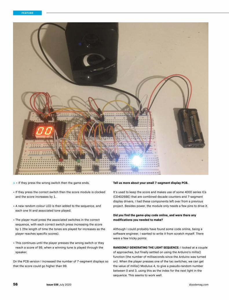
››• If they press the wrong switch then the game ends.
• If they press the correct switch then the score module is clocked and the score increases by 1.
• A new random colour LED is then added to the sequence, and each one lit and associated tone played.
• The player must press the associated switches in the correct sequence, with each correct switch press increasing the score by 1 (the length of time the tones are played for increases as the player reaches specific scores).
• This continues until the player presses the wrong switch or they reach a score of 99, when a winning tune is played through the speaker.
On the PCB version I increased the number of 7-segment displays so that the score could go higher than 99.
Tell us more about your small 7-segment display PCB.
It’s used to keep the score and makes use of some 4000 series ICs (CD4026BE) that are combined decade counters and 7-segment display drivers, I had these components left over from a previous project. Besides power, the module only needs a few pins to drive it.
Did you find the game-play code online, and were there any modifications you needed to make?
Although I could probably have found some code online, being a software engineer, I wanted to write it from scratch myself. There were a few tricky points:
RANDOMLY GENERATING THE LIGHT SEQUENCE: I looked at a couple of approaches, but finally settled on using the Arduino’s millis() function (the number of milliseconds since the Arduino was turned on). When the player presses one of the tac switches, we can get the value of millis() Modulus 4, to give a pseudo-random number between 0 and 3, using this as the index for the next light in the sequence. This seems to work well.
Issue 036 July 2020 diyodemag.com56
FEATURE
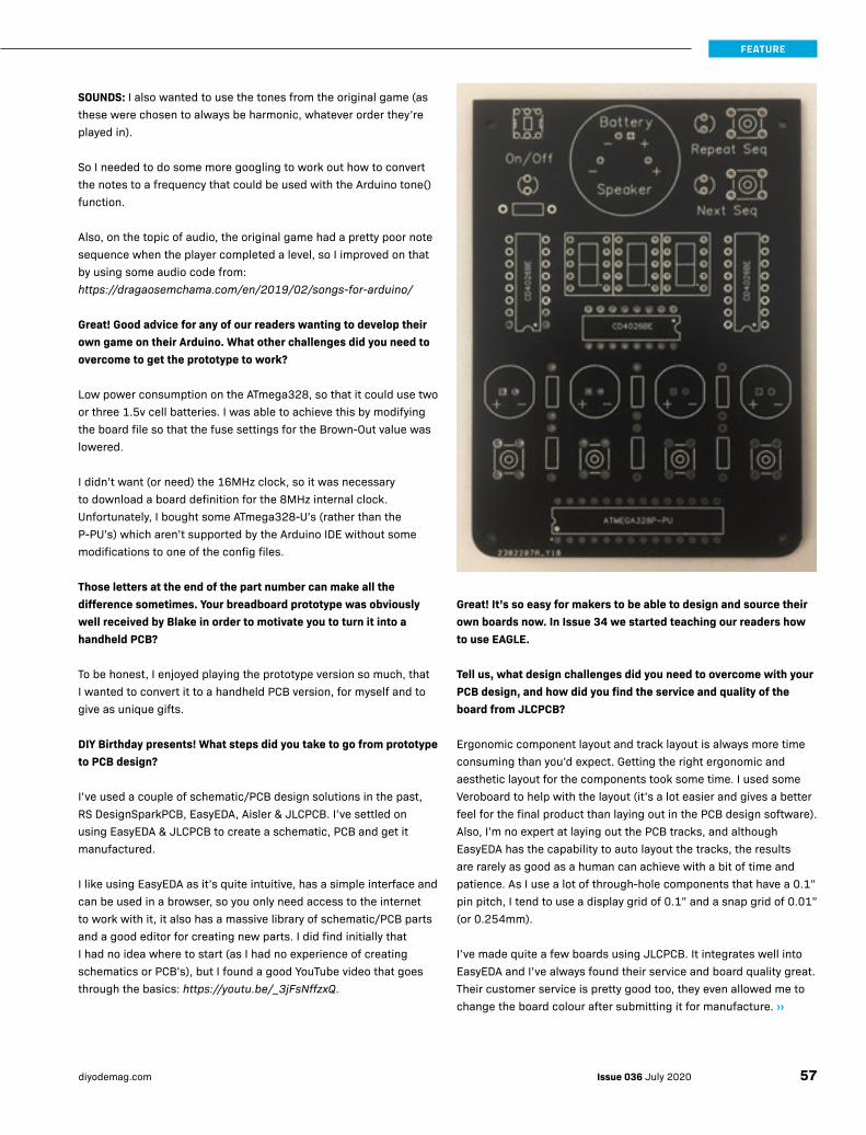
SOUNDS: I also wanted to use the tones from the original game (as these were chosen to always be harmonic, whatever order they’re played in).
So I needed to do some more googling to work out how to convert the notes to a frequency that could be used with the Arduino tone() function.
Also, on the topic of audio, the original game had a pretty poor note sequence when the player completed a level, so I improved on that by using some audio code from: https://dragaosemchama.com/en/2019/02/songs-for-arduino/
Great! Good advice for any of our readers wanting to develop their own game on their Arduino. What other challenges did you need to overcome to get the prototype to work?
Low power consumption on the ATmega328, so that it could use two or three 1.5v cell batteries. I was able to achieve this by modifying the board file so that the fuse settings for the Brown-Out value was lowered.
I didn’t want (or need) the 16MHz clock, so it was necessary to download a board definition for the 8MHz internal clock. Unfortunately, I bought some ATmega328-U’s (rather than the P-PU’s) which aren’t supported by the Arduino IDE without some modifications to one of the config files.
Those letters at the end of the part number can make all the difference sometimes. Your breadboard prototype was obviously well received by Blake in order to motivate you to turn it into a handheld PCB?
To be honest, I enjoyed playing the prototype version so much, that I wanted to convert it to a handheld PCB version, for myself and to give as unique gifts.
DIY Birthday presents! What steps did you take to go from prototype to PCB design?
I’ve used a couple of schematic/PCB design solutions in the past, RS DesignSparkPCB, EasyEDA, Aisler & JLCPCB. I’ve settled on using EasyEDA & JLCPCB to create a schematic, PCB and get it manufactured.
I like using EasyEDA as it’s quite intuitive, has a simple interface and can be used in a browser, so you only need access to the internet to work with it, it also has a massive library of schematic/PCB parts and a good editor for creating new parts. I did find initially that I had no idea where to start (as I had no experience of creating schematics or PCB’s), but I found a good YouTube video that goes through the basics: https://youtu.be/_3jFsNffzxQ.
Great! It’s so easy for makers to be able to design and source their own boards now. In Issue 34 we started teaching our readers how to use EAGLE.
Tell us, what design challenges did you need to overcome with your PCB design, and how did you find the service and quality of the board from JLCPCB?
Ergonomic component layout and track layout is always more time consuming than you’d expect. Getting the right ergonomic and aesthetic layout for the components took some time. I used some Veroboard to help with the layout (it’s a lot easier and gives a better feel for the final product than laying out in the PCB design software). Also, I’m no expert at laying out the PCB tracks, and although EasyEDA has the capability to auto layout the tracks, the results are rarely as good as a human can achieve with a bit of time and patience. As I use a lot of through-hole components that have a 0.1” pin pitch, I tend to use a display grid of 0.1” and a snap grid of 0.01” (or 0.254mm).
I’ve made quite a few boards using JLCPCB. It integrates well into EasyEDA and I’ve always found their service and board quality great. Their customer service is pretty good too, they even allowed me to change the board colour after submitting it for manufacture. ››
57Issue 036 July 2020diyodemag.com
FEATURE
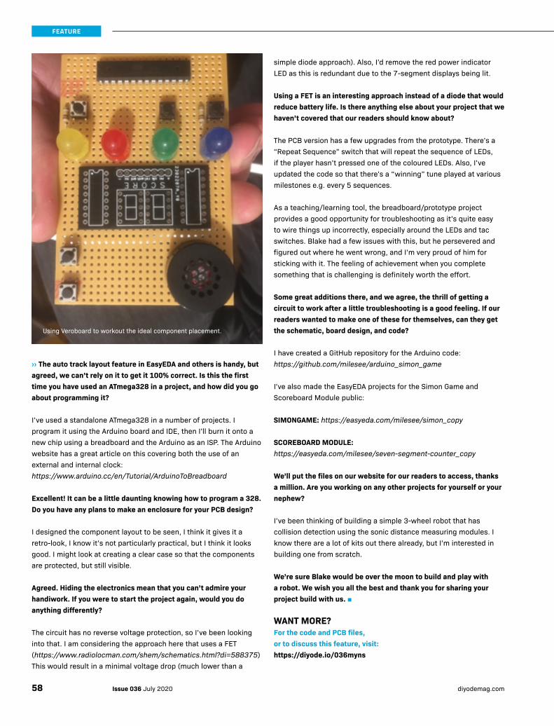
››The auto track layout feature in EasyEDA and others is handy, but agreed, we can’t rely on it to get it 100% correct. Is this the first time you have used an ATmega328 in a project, and how did you go about programming it?
I’ve used a standalone ATmega328 in a number of projects. I program it using the Arduino board and IDE, then I’ll burn it onto a new chip using a breadboard and the Arduino as an ISP. The Arduino website has a great article on this covering both the use of an external and internal clock: https://www.arduino.cc/en/Tutorial/ArduinoToBreadboard
Excellent! It can be a little daunting knowing how to program a 328. Do you have any plans to make an enclosure for your PCB design?
I designed the component layout to be seen, I think it gives it a retro-look, I know it’s not particularly practical, but I think it looks good. I might look at creating a clear case so that the components are protected, but still visible.
Agreed. Hiding the electronics mean that you can’t admire your handiwork. If you were to start the project again, would you do anything differently?
The circuit has no reverse voltage protection, so I’ve been looking into that. I am considering the approach here that uses a FET (https://www.radiolocman.com/shem/schematics.html?di=588375) This would result in a minimal voltage drop (much lower than a
Using Veroboard to workout the ideal component placement.
simple diode approach). Also, I’d remove the red power indicator LED as this is redundant due to the 7-segment displays being lit.
Using a FET is an interesting approach instead of a diode that would reduce battery life. Is there anything else about your project that we haven’t covered that our readers should know about?
The PCB version has a few upgrades from the prototype. There’s a “Repeat Sequence” switch that will repeat the sequence of LEDs, if the player hasn’t pressed one of the coloured LEDs. Also, I’ve updated the code so that there’s a “winning” tune played at various milestones e.g. every 5 sequences.
As a teaching/learning tool, the breadboard/prototype project provides a good opportunity for troubleshooting as it’s quite easy to wire things up incorrectly, especially around the LEDs and tac switches. Blake had a few issues with this, but he persevered and figured out where he went wrong, and I’m very proud of him for sticking with it. The feeling of achievement when you complete something that is challenging is definitely worth the effort.
Some great additions there, and we agree, the thrill of getting a circuit to work after a little troubleshooting is a good feeling. If our readers wanted to make one of these for themselves, can they get the schematic, board design, and code?
I have created a GitHub repository for the Arduino code: https://github.com/milesee/arduino_simon_game
I've also made the EasyEDA projects for the Simon Game and Scoreboard Module public:
SIMONGAME: https://easyeda.com/milesee/simon_copy
SCOREBOARD MODULE: https://easyeda.com/milesee/seven-segment-counter_copy
We’ll put the files on our website for our readers to access, thanks a million. Are you working on any other projects for yourself or your nephew?
I’ve been thinking of building a simple 3-wheel robot that has collision detection using the sonic distance measuring modules. I know there are a lot of kits out there already, but I’m interested in building one from scratch.
We’re sure Blake would be over the moon to build and play with a robot. We wish you all the best and thank you for sharing your project build with us. ■
WANT MORE?For the code and PCB files, or to discuss this feature, visit:https://diyode.io/036myns
Issue 036 July 2020 diyodemag.com58
FEATURE

Dream like a child. Build like a machine.
www.altronics.com.au | 1300 797 007
DIYODE-Back_Cover_v1.indd 3 6/06/2017 1:02 PM

PERSISTENT POWERArduino-based
High Capacity 12V UPS
BUILD TIME: 4 HOURS (+ 3D PRINTING TIME) DIFFICULTY RATING: INTERMEDIATE
With broadband replacing fixed-line phones, keeping the power on during blackouts is essential, as the horrific bushfire season in Australia showed us recently. This UPS is designed to power your modem/WiFi router, providing essential phone and Internet service for several hours.
Impressively, it is able to supply up to 5A for over an hour, and can also supply high short-term peak currents to run devices such as a 12V compressor fridge.
THE BROAD OVERVIEW
Our 12V UPS is designed to go in series with the 12V power supply that powers the device you want to keep running during a blackout, such as a broadband router.
The UPS uses the newest LiPoFE4 lithium battery technology (they don’t catch on fire as Li-ion can), which is charged thanks to the onboard Boost module.
We use an Arduino Pro Mini running in a low power mode and with its power LED removed to conserve power, a colour OLED display, and solid-state MOSFET switches.
A custom-designed 3D printed enclosure rounds out the project.
Build this 12V uninterruptible power supply to keep your broadband and other important tech running during a blackout.
GEOFF COHENWriter, programmer, and maker.
thingiverse.com/geoff_cohen/designs
Issue 036 July 2020 diyodemag.com60
PROJECT
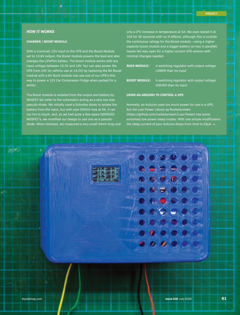
HOW IT WORKS
CHARGER / BOOST MODULE
With a (nominal) 12V input to the UPS and the Boost Module set to 13.6V output, the Boost module powers the load and also charges the LiFePO4 battery. The boost module works with any input voltage between 10.5V and 13V. You can also power the UPS from 24V (or vehicle use at 14.2V) by replacing the 6A Boost module with a 6A Buck module (we use one of our UPS’s this way to power a 12V Car Compressor fridge when parked for a while).
The Boost module is isolated from the output and battery by MOSFET Q4 (refer to the schematic) acting as a very low loss pseudo-diode. We initially used a Schottky diode to isolate the battery from the input, but with over 500mV loss at 5A, it ran too hot to touch, and, as we had quite a few spare NDP6020 MOSFET’s, we modified our design to use one as a pseudo-diode. When checked, we measured a very small 54mV drop and
only a 2°C increase in temperature at 5A. We even tested it at 10A for 30 seconds with no ill effects, although this is outside the continuous ratings for the Boost module - using a higher capacity boost module and a bigger battery (or two in parallel) leaves the way open for a higher current UPS version with minimal changes needed.
BUCK MODULE: A switching regulator with output voltage LOWER than its input
BOOST MODULE: A switching regulator with output voltage HIGHER than its input
USING AN ARDUINO TO CONTROL A UPS
Normally, an Arduino uses too much power for use in a UPS, but the Low Power Library by Rocketscream (https://github.com/rocketscream/Low-Power) has some extremely low power sleep modes. With one simple modification, the sleep current of your Arduino drops from 3mA to 25μA. ››
Issue 036 July 2020diyodemag.com 61
PROJECT

››As an example of how useful this is, when your UPS battery is nearly flat (approximately 1.5% capacity left in our 7AH battery). 3mA would exhaust a nearly flat battery in just one day, however, by just removing the Arduino Pro Mini’s power LED, the same, nearly flat, battery would last over 2 months (hopefully mains power won’t be out that long).
In our UPS, when it’s battery powered, if the battery is nearly flat and the voltage drops below 12V, the Arduino Pro Mini first isolates the battery (by turning off MOSFET Q1) then the Arduino switches to low-power SLEEP mode, consuming only 25μA, preventing the battery going completely flat for months. The Arduino code then periodically (once a second) wakes up for approximately 200 microseconds, checks to see if the input power is back on and resumes normal operation if it is. Using this simple method of operation only increases the average SLEEP power used by 0.02% percent.
We selected an Arduino Pro Mini for this project. Having no USB Port that would be drawing several mA, it is one of a few Arduinos that can run in very low power mode, drawing only 25µA in sleep mode. The only change needed is to remove the Arduino board’s power LED.
ARDUINO PRO MINI LOW POWER DETAILS
ATMEGA328P PRO MINI POWER INPUT MODE CURRENT
ORIGINAL – UNCHANGED RAW Pin Active 21mA
ORIGINAL – UNCHANGED RAW Pin Sleep 3mA
NO POWER LED RAW Pin Active 18mA
NO POWER LED RAW Pin Sleep 25μA
NO POWER LED, NO REGULATOR VCC Pin Active 13mA
NO POWER LED, NO REGULATOR VCC Pin Sleep 6 μA
We also encountered problems on some Arduino compatible boards with their internal voltage regulator dying when more than 12V was applied to the RAW input, so we used seven series-connected 1N914 diodes to drop the RAW voltage from 13.6V down to (approximately) 9V and have had no more problems. We didn’t use a Zener as they tend to not work at very low currents, in this case, 25μA in SLEEP mode.
MOSFET (Q1)
MOSFET (Q1) needs a small heatsink because, when charging a very flat LiFePO4 battery, the internal diode in MOSFET Q1 forward conducts and produces some heat. Only a small heatsink is required. We used a couple of Raspberry Pi adhesive heatsinks,
but any similar sized one will work, even a 12mm x 12mm piece of Aluminium screwed to Q1 would work.
Once the battery is moderately charged, this diode stops conducting, then the battery charging current is limited to 3A, using PWM (Pulse Width Modulation) control from Arduino output D3. Q2 acts as a level converter with resistors R5 and R6 limiting the gate voltage (VGSS) to Q1, as it’s rather low at only 8V. This method is also used with R19, R20, Q3, and Q4.
MEASURING VOLTAGE AND CURRENT
As the Arduino can't measure negative voltages, we used three different earth (or more accurately, 0V reference) points: the 12V and Boost GND input, battery GND, and output GND. Of course, at full current there is only 0.025x5 or 125mV difference between each one. The battery current is not measured directly, but calculated from the difference between input and output current. You can examine the code in function readAllAnalogInputs() (in file DIYODE-12V-UPS-Mk2.ino - near line 470). The voltages are measured via the 15:1 voltage dividers (R3/R4, R8/R9, R11/R12) into the Arduino board’s analog inputs, with some maths being performed to allow for the slight difference between the three ground reference points.
LIFEPO4 BATTERY
We were pleased when we noticed Jaycar had added a 12V/7AH LiFePO4 battery to their products. LiFePO4 batteries are much safer, they don’t catch fire (unlike Li-ion), and having an internal BMS (Battery Management System) makes charging much simpler, with each internal cell receiving a balanced charge. LiFePO4 cells are also relatively forgiving and can be fully charged by any voltage between 3.4V and 4.2V per cell, although 3.4 - 3.6 are considered optimal. The BMS should also prevent damage to the LiFePO4 battery if it ever goes completely flat, but minimising that risk is always a better option.
COOLING FAN OPTION
Although we haven’t needed one yet, we have allocated space for a 40mm cooling fan that you can add if you are running high loads (eg. 6A) 24/7 or live in hot climates, such as the NT or FNQ.
OLED SCREEN
A 0.96” I2C OLED display module is used to show exactly how the UPS is performing, displaying voltage and current for the input, battery and output.
Note: We are currently adding code to show the battery charge %, which should be available by the time we go to print. ››
Issue 036 July 2020 diyodemag.com62
PROJECT
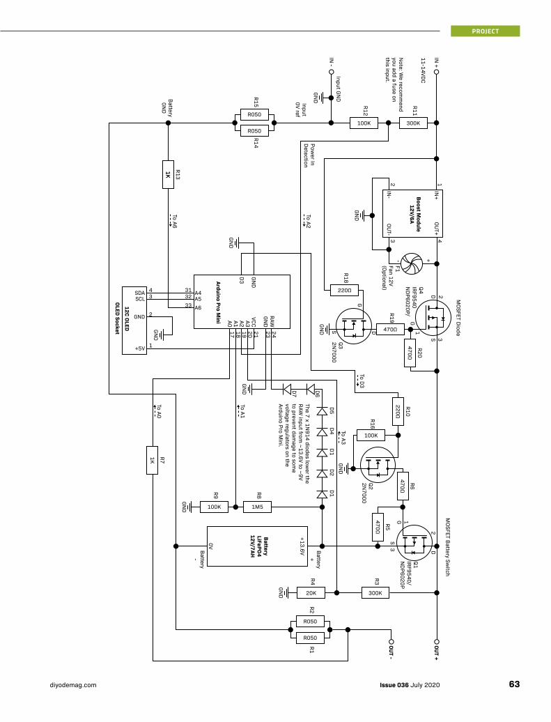
R050
R1
R050
R2
20K
R4
1M5
R8
100K
R9
100K
R16
470Ω
R19
220Ω
R18
100K
R12
300K
R11
300K
R3470Ω
R5
470Ω
R6
220Ω
R10470Ω
R20
1K R71K
R13
1K
OUT -
BatteryLiFePO412V/7AH
12C OLED
MOSFET B
attery Switch
MOSFET Diode
Boost Module
12V/6A
OUT +
Q1IRF9540/N
DP6020P
Q4IRF9540N
DP6020P/
F1Fan 12V (Optional)
Q22N7000
Q32N7000
2D
1
GND
GND
GND
GND
RAW24232120191817
GND
GND
IN+
43IN
-
OUT+1
+-2
OUT-
VCCA3A2D3
A1A0
SDA 43
313233
2
1
SCLA4A5A6
GND
+5V
To A3
GND
+13.6V
0V
GND
To A1
To A6
To A2
To A0
To D3
D1D2
D1D4
D5
D6D7
R050
R14
R050
R15
IN -
IN +
11-14VDC
GND
GND
GND
Input0V ref
23
1
DS
G
DS
G
Arduino Pro Mini
Battery -
3S
G
The 7 x 1N914 diodes low
er the RAW
input from ~13.6V to ~9V
to prevent damage to som
e voltage regulators on the Arduino Pro M
ini.
Note: W
e recomm
end you add a fuse on this inpu t.
BatteryGN
D
Power In
Detection
Battery +
OLED Socket
Input GND
63Issue 036 July 2020diyodemag.com
PROJECT
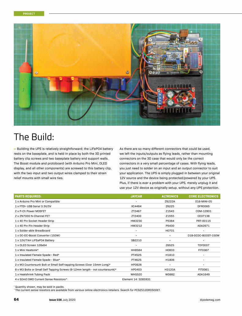
The Build:››Building the UPS is relatively straightforward; the LiFePO4 battery rests on the baseplate, and is held In place by both the 3D printed battery clip screws and two baseplate battery end support walls. The Boost module and protoboard (with Arduino Pro Mini, OLED display, and all other components) are screwed to this battery clip, with the two input and two output wires clamped to their strain relief mounts with small wire ties.
As there are so many different connectors that could be used, we left the inputs/outputs as flying leads, rather than mounting connectors on the 3D case that would only be the correct connectors in a very small percentage of cases. With flying leads, you just need to solder on an input and an output connector to suit your application. The UPS is simply plugged in between your original 12V source and the device being protected/powered by your UPS. Plus, if there is ever a problem with your UPS, merely unplug it and use your 12V device as originally setup, without any UPS protection.
PARTS REQUIRED: JAYCAR ALTRONICS CORE ELECTRONICS1 x Arduino Pro Mini or Compatible - Z6222A 018-MINI-05
1 x FTDI- USB Serial 3.3V/5V XC4464 Z6225 DFR0065
2 x P-Ch Power MOSFET ZT2467 Z1543 COM-12901
2 x 2N7000 N-Channel FET ZT2400 Z1555 CE07138
1 x 40 Pin Socket Header Strip HM3230 P5384 PRT-00115
1 x 40 Pin Pin Header Strip HM3212 P5430 ADA2671
1 x Solder-able Breadboard - H0701 -
1 x DC-DC-Boost Converter (150W) - - 018-DCDC-BOOST-150W
1 x 12V/7AH LiFEePO4 Battery SB2210 - -
1 x OLED Screen 128x64 - Z6525 TOY0007
1 x Mini Heatsink* HH8584 H0603 FIT0367
1 x Insulated Female Spade - Red* PT4525 H1810 -
1 x Insulated Female Spade - Blue* PT4625 H1806 -
2 x M3 Countersunk Bolt or Small Self-tapping Screws (Over 15mm Long)* HP0626 - -
8 x M3 Bolts or Small Self Tapping Screws (8-12mm length - not countersunk)* HP0403 H3120A FIT0061
1 x Heatshrink Tubing Pack WH5520 W0882 ADA1649
4 x 50mΩ SMD Current Sense Resistors^ Element 14: 3285931
* Quantity shown, may be sold in packs. ^ The current sense resistors are available from various online electronics retailers. Search for PCS2512DR0500ET.
Issue 036 July 2020 diyodemag.com64
PROJECT
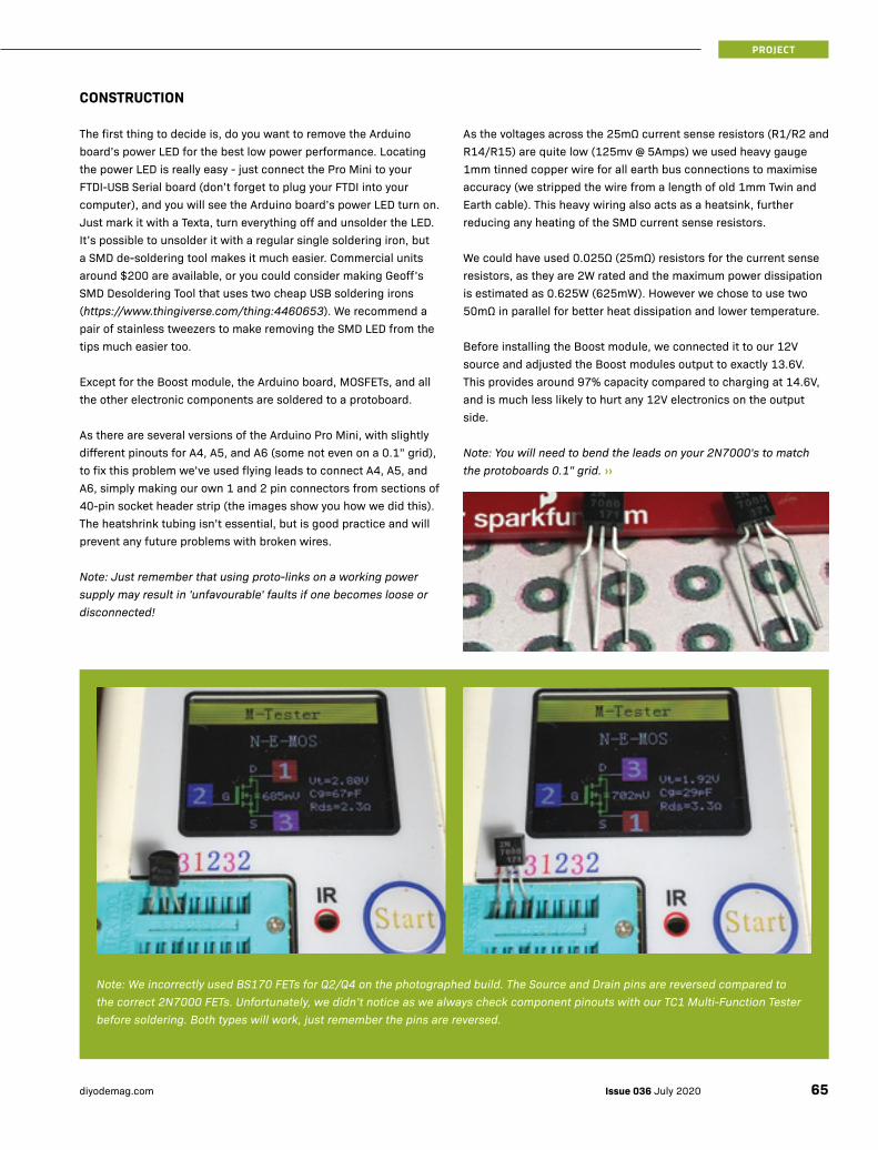
CONSTRUCTION
The first thing to decide is, do you want to remove the Arduino board’s power LED for the best low power performance. Locating the power LED is really easy - just connect the Pro Mini to your FTDI-USB Serial board (don’t forget to plug your FTDI into your computer), and you will see the Arduino board’s power LED turn on. Just mark it with a Texta, turn everything off and unsolder the LED. It’s possible to unsolder it with a regular single soldering iron, but a SMD de-soldering tool makes it much easier. Commercial units around $200 are available, or you could consider making Geoff’s SMD Desoldering Tool that uses two cheap USB soldering irons (https://www.thingiverse.com/thing:4460653). We recommend a pair of stainless tweezers to make removing the SMD LED from the tips much easier too.
Except for the Boost module, the Arduino board, MOSFETs, and all the other electronic components are soldered to a protoboard.
As there are several versions of the Arduino Pro Mini, with slightly different pinouts for A4, A5, and A6 (some not even on a 0.1” grid), to fix this problem we’ve used flying leads to connect A4, A5, and A6, simply making our own 1 and 2 pin connectors from sections of 40-pin socket header strip (the images show you how we did this). The heatshrink tubing isn’t essential, but is good practice and will prevent any future problems with broken wires.
Note: Just remember that using proto-links on a working power supply may result in 'unfavourable' faults if one becomes loose or disconnected!
As the voltages across the 25mΩ current sense resistors (R1/R2 and R14/R15) are quite low (125mv @ 5Amps) we used heavy gauge 1mm tinned copper wire for all earth bus connections to maximise accuracy (we stripped the wire from a length of old 1mm Twin and Earth cable). This heavy wiring also acts as a heatsink, further reducing any heating of the SMD current sense resistors.
We could have used 0.025Ω (25mΩ) resistors for the current sense resistors, as they are 2W rated and the maximum power dissipation is estimated as 0.625W (625mW). However we chose to use two 50mΩ in parallel for better heat dissipation and lower temperature.
Before installing the Boost module, we connected it to our 12V source and adjusted the Boost modules output to exactly 13.6V. This provides around 97% capacity compared to charging at 14.6V, and is much less likely to hurt any 12V electronics on the output side.
Note: You will need to bend the leads on your 2N7000's to match the protoboards 0.1" grid. ››
Note: We incorrectly used BS170 FETs for Q2/Q4 on the photographed build. The Source and Drain pins are reversed compared to the correct 2N7000 FETs. Unfortunately, we didn’t notice as we always check component pinouts with our TC1 Multi-Function Tester before soldering. Both types will work, just remember the pins are reversed.
65Issue 036 July 2020diyodemag.com
PROJECT

››THE CODE
Firstly, if not in your Arduino Library, you will need to install these libraries by selecting Sketch > Include Library > Add .ZIP Library: https://github.com/rocketscream/Low-Power https://github.com/adafruit/Adafruit_SSD1306
The code for this project can be downloaded from our website.
Note: If you have both an FTDI USB-Serial board and Arduino Pro Mini with the same polarity FTDI programming connectors don’t despair, just do what we did, cut two 6-way lengths from your 40-way socket strip and solder them together to make an adapter.
We originally tried using the Arduino with interrupt driven code, but it just couldn’t switch fast enough. Our 300MHz Tektronix CRO showed BIG switching spikes, so we finally settled on a design with the battery always connected. Now, when the 12V input goes off, there is not the slightest sign of a switching spike. You can only tell the input 12V went off by looking at the display.
If you are really keen, you can even calibrate the voltage and current exactly by measuring it with an accurate meter and then adjusting vRefMultIn, vRefMultOut, vRefMultBat and aRefMultOut (In file DIYODE-12V-UPS-Mk2.ino, near line 121) so the values displayed on the UPS’s OLED display match your measured values. For extra accuracy, you can even display these values with 2 decimal point accuracy (at the cost of a smaller font) by changing the decimalPoints variable (around line 81) from 1 to 2. Just remember to change it back if you prefer the bigger fonts as we do. We used some existing sense resistors (of unknown accuracy), but using more accurate resistors (0.5% or 1%) makes extra calibration of current with aRefMultOut unnecessary.
Issue 036 July 2020 diyodemag.com66
PROJECT

We have put in a lot of explanatory comments, so you should have minimal problems modifying our code.
TESTING
Initially, leave the battery (Brown & Blue wires) and output (Yellow & Green wires) unconnected, then supply between 10.5V and 13V to the input leads (Red & Black wires). You will see the OLED display turn on with three separate sections - the top section displays the output voltage and current, which should be close to 13.6V. The centre section shows the input voltage and current, and the lower section displaying the battery voltage and current. With only an input and no battery or output load, all currents should be close to zero. You can now connect the LiFePO4 battery, and unless the battery is fully charged, both input and battery will display some current flow, and if you disconnect the input power, the display will change to "On Battery".
With these tests completed, you can now reconnect the input power and also connect a load to the output e.g. NBN Modem. All three sections will display their respective voltage and current details, and the output will be powered with or without any input power. All that remains is to clip the top cover to the baseplate (sometimes a firm tap is needed to press the top cover's 20 recesses in place around the baseplate's 20 edge retaining clips.
Note: If the UPS is not needed for several months, remove the case top and unplug the battery to turn the UPS off.
3D PRINTED ENCLOSURE
We used PETG, but PLA would be OK for indoor use. We used support for the cover but it may be unnecessary, and it’s a real pain to clean out all the holes.
We’ve also provided two alignment clips that align the OLED display in the viewing window. If your Arduino has a male programming connector you may only be able to use the bigger alignment clip.
In our early designs, there wasn’t quite enough pressure to hold the top in place. We just warmed the top cover edges with a hot air gun,
pressed inwards, and let it cool (for our build, the cover is so tight we need to push a spudger in quite hard to separate the lid and baseplate). We have modified the design to minimise this problem with some extra reinforcing, both inside the top cover, battery clip, and around the baseplate edges.
Assembly is easy! First, place the battery on the baseplate, put the battery clip in place and use two countersunk M3 (or self-tapping screws) to hold everything together. Then use four screws to hold the Boost module in place, after removing the four spacers on the Boost module (only if it has some, of course). Then screw the proto-board in place and clamp the input and output wires to their strain reliefs. We recommend looking carefully at the pictures we have provided, which are the best way to check the correct orientation of all parts.
WHERE TO FROM HERE?
If you are handy with circuit board design, you could make a PCB for the project, which would make it much quicker to build and reduce assembly errors.
A few other ideas include:
• Modify the source code to show battery power/time/% left to run.
• Run two (or more) batteries in parallel so your UPS runs longer under battery power.
• Put in a bigger Boost (or Buck) module for higher power.
• Add an ESP-01 for telemetry and send UPS status to phone/PC etc.
• Experiment with higher output currents (10-15 Amps) by adding a heatsink for both NDP6020 MOSFETS and changing the current sense resistors. ■
WANT MORE? For the code and 3D print files, or to discuss this project, visit: https://diyode.io/036nmkc
BATTERY CLIP TOP COVER BASEPLATEOLED ALIGNMENT
CLIPS
67Issue 036 July 2020diyodemag.com
PROJECT
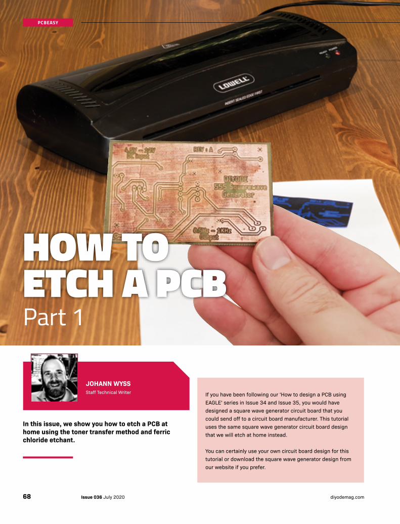
JOHANN WYSSStaff Technical Writer
In this issue, we show you how to etch a PCB at home using the toner transfer method and ferric chloride etchant.
If you have been following our 'How to design a PCB using EAGLE' series in Issue 34 and Issue 35, you would have designed a square wave generator circuit board that you could send off to a circuit board manufacturer. This tutorial uses the same square wave generator circuit board design that we will etch at home instead.
You can certainly use your own circuit board design for this tutorial or download the square wave generator design from our website if you prefer.
HOW TO ETCH A PCBPart 1
Issue 036 July 2020 diyodemag.com68
PCBEASY
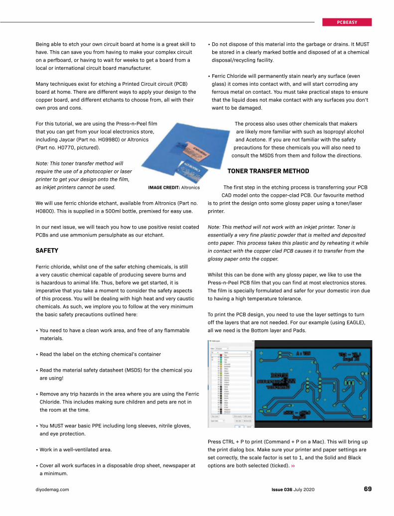
Being able to etch your own circuit board at home is a great skill to have. This can save you from having to make your complex circuit on a perfboard, or having to wait for weeks to get a board from a local or international circuit board manufacturer.
Many techniques exist for etching a Printed Circuit circuit (PCB) board at home. There are different ways to apply your design to the copper board, and different etchants to choose from, all with their own pros and cons.
For this tutorial, we are using the Press-n-Peel film that you can get from your local electronics store, including Jaycar (Part no. HG9980) or Altronics (Part no. H0770, pictured).
Note: This toner transfer method will require the use of a photocopier or laser printer to get your design onto the film, as inkjet printers cannot be used.
We will use ferric chloride etchant, available from Altronics (Part no. H0800). This is supplied in a 500ml bottle, premixed for easy use.
In our next issue, we will teach you how to use positive resist coated PCBs and use ammonium persulphate as our etchant.
SAFETY
Ferric chloride, whilst one of the safer etching chemicals, is still a very caustic chemical capable of producing severe burns and is hazardous to animal life. Thus, before we get started, it is imperative that you take a moment to consider the safety aspects of this process. You will be dealing with high heat and very caustic chemicals. As such, we implore you to follow at the very minimum the basic safety precautions outlined here:
• You need to have a clean work area, and free of any flammable materials.
• Read the label on the etching chemical’s container
• Read the material safety datasheet (MSDS) for the chemical you are using!
• Remove any trip hazards in the area where you are using the Ferric Chloride. This includes making sure children and pets are not in the room at the time.
• You MUST wear basic PPE including long sleeves, nitrile gloves, and eye protection.
• Work in a well-ventilated area.
• Cover all work surfaces in a disposable drop sheet, newspaper at a minimum.
• Do not dispose of this material into the garbage or drains. It MUST be stored in a clearly marked bottle and disposed of at a chemical disposal/recycling facility.
• Ferric Chloride will permanently stain nearly any surface (even glass) it comes into contact with, and will start corroding any ferrous metal on contact. You must take practical steps to ensure that the liquid does not make contact with any surfaces you don’t want to be damaged.
The process also uses other chemicals that makers are likely more familiar with such as Isopropyl alcohol and Acetone. If you are not familiar with the safety
precautions for these chemicals you will also need to consult the MSDS from them and follow the directions.
TONER TRANSFER METHOD
The first step in the etching process is transferring your PCB CAD model onto the copper-clad PCB. Our favourite method
is to print the design onto some glossy paper using a toner/laser printer.
Note: This method will not work with an inkjet printer. Toner is essentially a very fine plastic powder that is melted and deposited onto paper. This process takes this plastic and by reheating it while in contact with the copper clad PCB causes it to transfer from the glossy paper onto the copper.
Whilst this can be done with any glossy paper, we like to use the Press-n-Peel PCB film that you can find at most electronics stores. The film is specially formulated and safer for your domestic iron due to having a high temperature tolerance.
To print the PCB design, you need to use the layer settings to turn off the layers that are not needed. For our example (using EAGLE), all we need is the Bottom layer and Pads.
Press CTRL + P to print (Command + P on a Mac). This will bring up the print dialog box. Make sure your printer and paper settings are set correctly, the scale factor is set to 1, and the Solid and Black options are both selected (ticked). ››
IMAGE CREDIT: Altronics
69Issue 036 July 2020diyodemag.com
PCBEASY
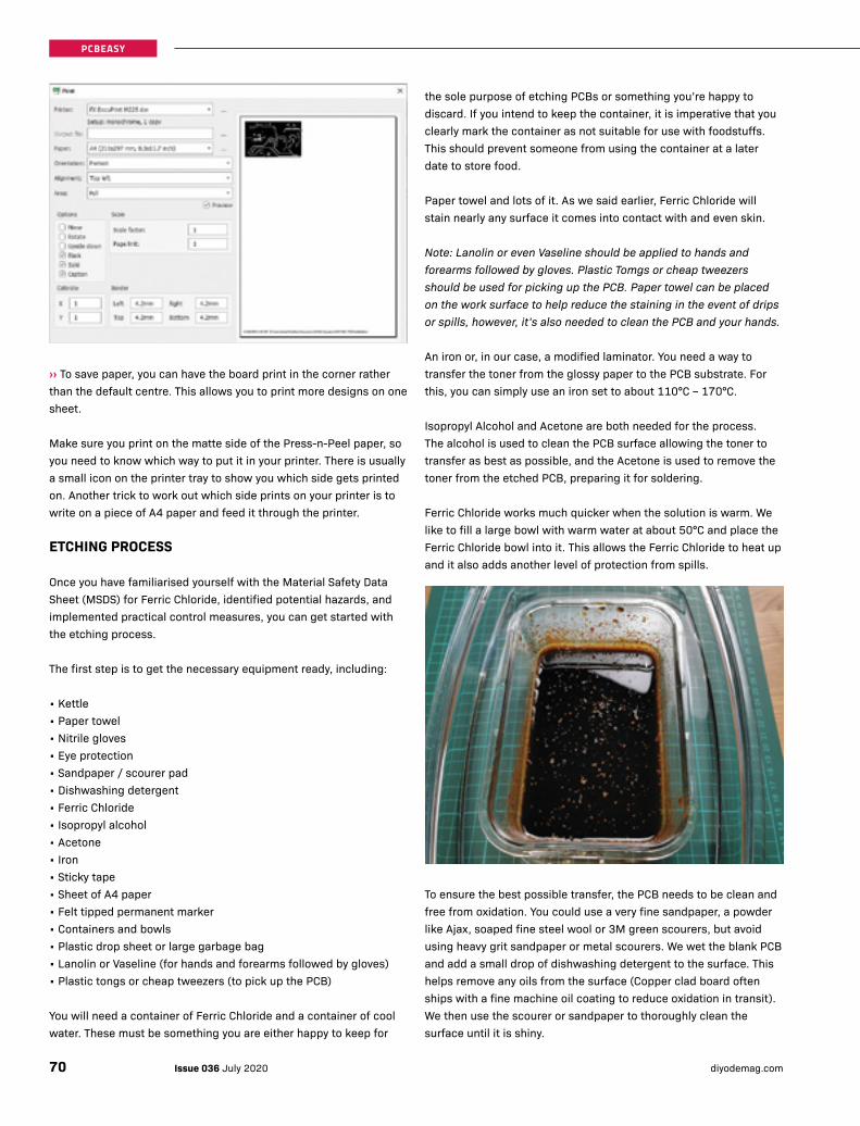
››To save paper, you can have the board print in the corner rather than the default centre. This allows you to print more designs on one sheet.
Make sure you print on the matte side of the Press-n-Peel paper, so you need to know which way to put it in your printer. There is usually a small icon on the printer tray to show you which side gets printed on. Another trick to work out which side prints on your printer is to write on a piece of A4 paper and feed it through the printer.
ETCHING PROCESS
Once you have familiarised yourself with the Material Safety Data Sheet (MSDS) for Ferric Chloride, identified potential hazards, and implemented practical control measures, you can get started with the etching process.
The first step is to get the necessary equipment ready, including:
• Kettle• Paper towel• Nitrile gloves• Eye protection• Sandpaper / scourer pad• Dishwashing detergent• Ferric Chloride• Isopropyl alcohol• Acetone• Iron• Sticky tape• Sheet of A4 paper• Felt tipped permanent marker• Containers and bowls• Plastic drop sheet or large garbage bag• Lanolin or Vaseline (for hands and forearms followed by gloves)• Plastic tongs or cheap tweezers (to pick up the PCB)
You will need a container of Ferric Chloride and a container of cool water. These must be something you are either happy to keep for
the sole purpose of etching PCBs or something you’re happy to discard. If you intend to keep the container, it is imperative that you clearly mark the container as not suitable for use with foodstuffs. This should prevent someone from using the container at a later date to store food.
Paper towel and lots of it. As we said earlier, Ferric Chloride will stain nearly any surface it comes into contact with and even skin.
Note: Lanolin or even Vaseline should be applied to hands and forearms followed by gloves. Plastic Tomgs or cheap tweezers should be used for picking up the PCB. Paper towel can be placed on the work surface to help reduce the staining in the event of drips or spills, however, it’s also needed to clean the PCB and your hands.
An iron or, in our case, a modified laminator. You need a way to transfer the toner from the glossy paper to the PCB substrate. For this, you can simply use an iron set to about 110°C – 170°C.
Isopropyl Alcohol and Acetone are both needed for the process. The alcohol is used to clean the PCB surface allowing the toner to transfer as best as possible, and the Acetone is used to remove the toner from the etched PCB, preparing it for soldering.
Ferric Chloride works much quicker when the solution is warm. We like to fill a large bowl with warm water at about 50°C and place the Ferric Chloride bowl into it. This allows the Ferric Chloride to heat up and it also adds another level of protection from spills.
To ensure the best possible transfer, the PCB needs to be clean and free from oxidation. You could use a very fine sandpaper, a powder like Ajax, soaped fine steel wool or 3M green scourers, but avoid using heavy grit sandpaper or metal scourers. We wet the blank PCB and add a small drop of dishwashing detergent to the surface. This helps remove any oils from the surface (Copper clad board often ships with a fine machine oil coating to reduce oxidation in transit). We then use the scourer or sandpaper to thoroughly clean the surface until it is shiny.
Issue 036 July 2020 diyodemag.com70
PCBEASY
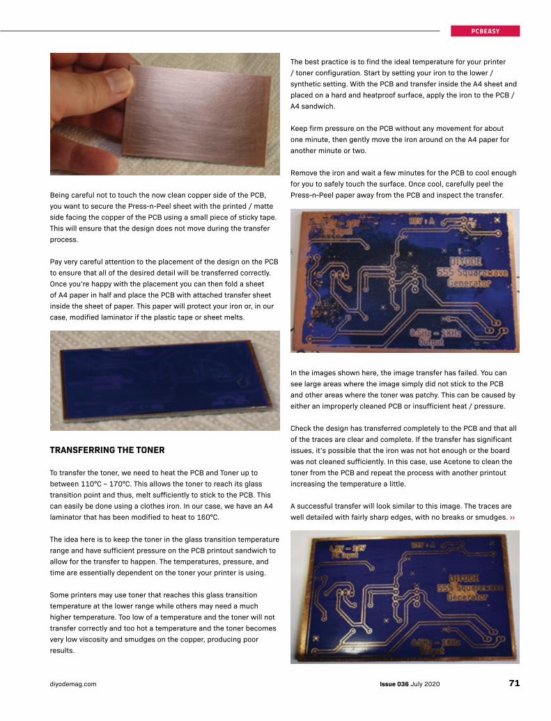
Being careful not to touch the now clean copper side of the PCB, you want to secure the Press-n-Peel sheet with the printed / matte side facing the copper of the PCB using a small piece of sticky tape. This will ensure that the design does not move during the transfer process.
Pay very careful attention to the placement of the design on the PCB to ensure that all of the desired detail will be transferred correctly. Once you’re happy with the placement you can then fold a sheet of A4 paper in half and place the PCB with attached transfer sheet inside the sheet of paper. This paper will protect your iron or, in our case, modified laminator if the plastic tape or sheet melts.
TRANSFERRING THE TONER
To transfer the toner, we need to heat the PCB and Toner up to between 110°C – 170°C. This allows the toner to reach its glass transition point and thus, melt sufficiently to stick to the PCB. This can easily be done using a clothes iron. In our case, we have an A4 laminator that has been modified to heat to 160°C.
The idea here is to keep the toner in the glass transition temperature range and have sufficient pressure on the PCB printout sandwich to allow for the transfer to happen. The temperatures, pressure, and time are essentially dependent on the toner your printer is using.
Some printers may use toner that reaches this glass transition temperature at the lower range while others may need a much higher temperature. Too low of a temperature and the toner will not transfer correctly and too hot a temperature and the toner becomes very low viscosity and smudges on the copper, producing poor results.
The best practice is to find the ideal temperature for your printer / toner configuration. Start by setting your iron to the lower / synthetic setting. With the PCB and transfer inside the A4 sheet and placed on a hard and heatproof surface, apply the iron to the PCB / A4 sandwich.
Keep firm pressure on the PCB without any movement for about one minute, then gently move the iron around on the A4 paper for another minute or two.
Remove the iron and wait a few minutes for the PCB to cool enough for you to safely touch the surface. Once cool, carefully peel the Press-n-Peel paper away from the PCB and inspect the transfer.
In the images shown here, the image transfer has failed. You can see large areas where the image simply did not stick to the PCB and other areas where the toner was patchy. This can be caused by either an improperly cleaned PCB or insufficient heat / pressure.
Check the design has transferred completely to the PCB and that all of the traces are clear and complete. If the transfer has significant issues, it’s possible that the iron was not hot enough or the board was not cleaned sufficiently. In this case, use Acetone to clean the toner from the PCB and repeat the process with another printout increasing the temperature a little.
A successful transfer will look similar to this image. The traces are well detailed with fairly sharp edges, with no breaks or smudges. ››
71Issue 036 July 2020diyodemag.com
PCBEASY
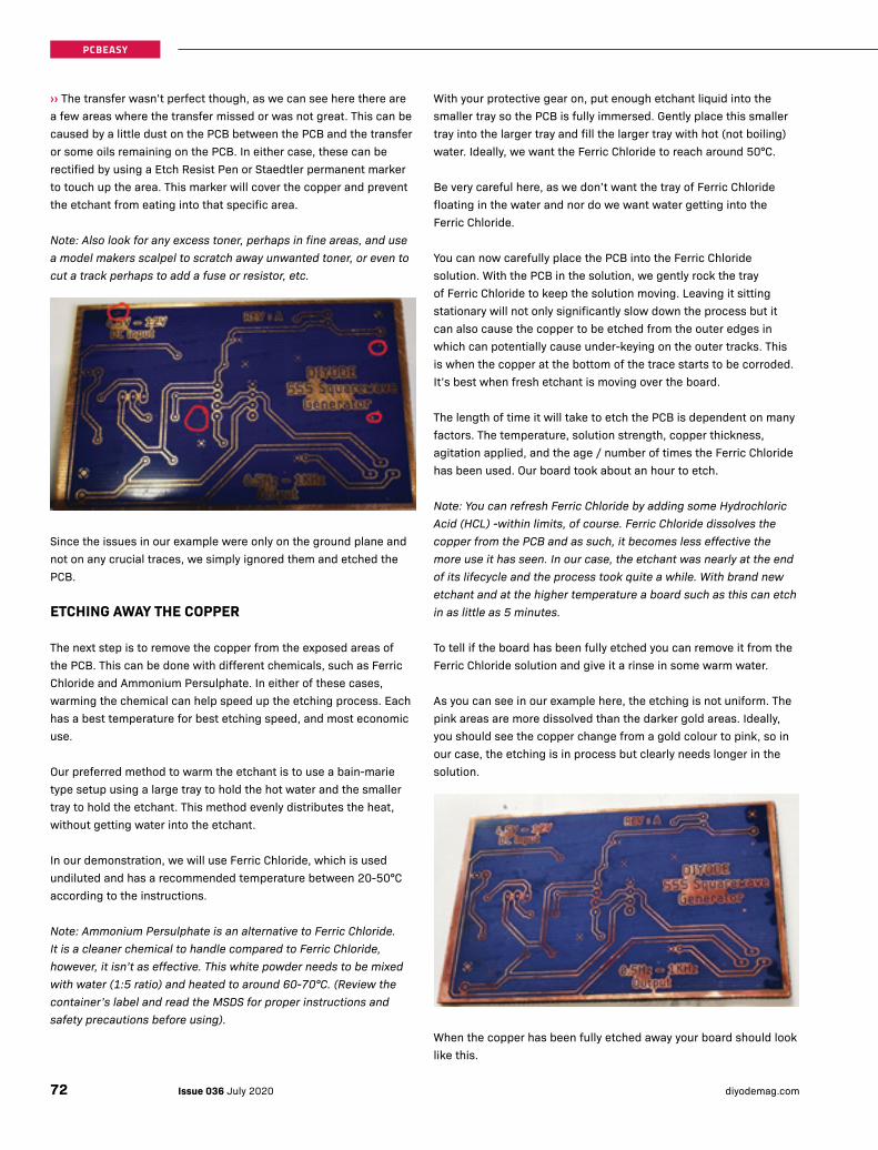
››The transfer wasn’t perfect though, as we can see here there are a few areas where the transfer missed or was not great. This can be caused by a little dust on the PCB between the PCB and the transfer or some oils remaining on the PCB. In either case, these can be rectified by using a Etch Resist Pen or Staedtler permanent marker to touch up the area. This marker will cover the copper and prevent the etchant from eating into that specific area.
Note: Also look for any excess toner, perhaps in fine areas, and use a model makers scalpel to scratch away unwanted toner, or even to cut a track perhaps to add a fuse or resistor, etc.
Since the issues in our example were only on the ground plane and not on any crucial traces, we simply ignored them and etched the PCB.
ETCHING AWAY THE COPPER
The next step is to remove the copper from the exposed areas of the PCB. This can be done with different chemicals, such as Ferric Chloride and Ammonium Persulphate. In either of these cases, warming the chemical can help speed up the etching process. Each has a best temperature for best etching speed, and most economic use.
Our preferred method to warm the etchant is to use a bain-marie type setup using a large tray to hold the hot water and the smaller tray to hold the etchant. This method evenly distributes the heat, without getting water into the etchant.
In our demonstration, we will use Ferric Chloride, which is used undiluted and has a recommended temperature between 20-50°C according to the instructions.
Note: Ammonium Persulphate is an alternative to Ferric Chloride. It is a cleaner chemical to handle compared to Ferric Chloride, however, it isn’t as effective. This white powder needs to be mixed with water (1:5 ratio) and heated to around 60-70°C. (Review the container’s label and read the MSDS for proper instructions and safety precautions before using).
With your protective gear on, put enough etchant liquid into the smaller tray so the PCB is fully immersed. Gently place this smaller tray into the larger tray and fill the larger tray with hot (not boiling) water. Ideally, we want the Ferric Chloride to reach around 50°C.
Be very careful here, as we don’t want the tray of Ferric Chloride floating in the water and nor do we want water getting into the Ferric Chloride.
You can now carefully place the PCB into the Ferric Chloride solution. With the PCB in the solution, we gently rock the tray of Ferric Chloride to keep the solution moving. Leaving it sitting stationary will not only significantly slow down the process but it can also cause the copper to be etched from the outer edges in which can potentially cause under-keying on the outer tracks. This is when the copper at the bottom of the trace starts to be corroded. It’s best when fresh etchant is moving over the board.
The length of time it will take to etch the PCB is dependent on many factors. The temperature, solution strength, copper thickness, agitation applied, and the age / number of times the Ferric Chloride has been used. Our board took about an hour to etch.
Note: You can refresh Ferric Chloride by adding some Hydrochloric Acid (HCL) -within limits, of course. Ferric Chloride dissolves the copper from the PCB and as such, it becomes less effective the more use it has seen. In our case, the etchant was nearly at the end of its lifecycle and the process took quite a while. With brand new etchant and at the higher temperature a board such as this can etch in as little as 5 minutes.
To tell if the board has been fully etched you can remove it from the Ferric Chloride solution and give it a rinse in some warm water.
As you can see in our example here, the etching is not uniform. The pink areas are more dissolved than the darker gold areas. Ideally, you should see the copper change from a gold colour to pink, so in our case, the etching is in process but clearly needs longer in the solution.
When the copper has been fully etched away your board should look like this.
Issue 036 July 2020 diyodemag.com72
PCBEASY
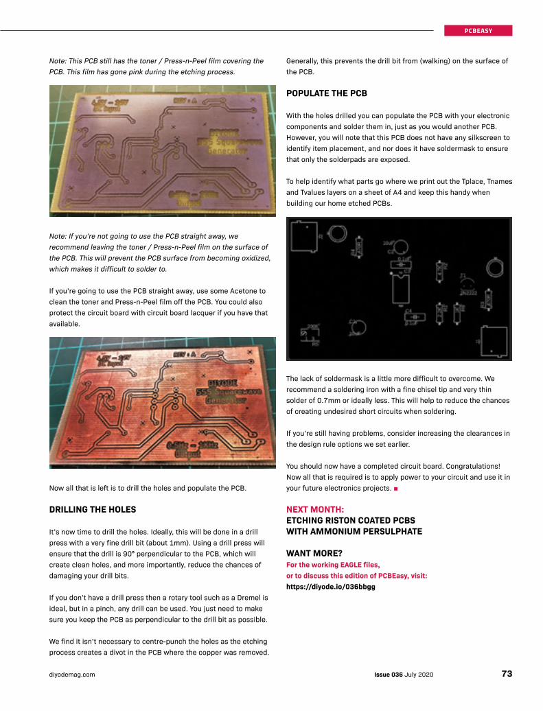
Note: This PCB still has the toner / Press-n-Peel film covering the PCB. This film has gone pink during the etching process.
Note: If you’re not going to use the PCB straight away, we recommend leaving the toner / Press-n-Peel film on the surface of the PCB. This will prevent the PCB surface from becoming oxidized, which makes it difficult to solder to.
If you’re going to use the PCB straight away, use some Acetone to clean the toner and Press-n-Peel film off the PCB. You could also protect the circuit board with circuit board lacquer if you have that available.
Now all that is left is to drill the holes and populate the PCB.
DRILLING THE HOLES
It’s now time to drill the holes. Ideally, this will be done in a drill press with a very fine drill bit (about 1mm). Using a drill press will ensure that the drill is 90° perpendicular to the PCB, which will create clean holes, and more importantly, reduce the chances of damaging your drill bits.
If you don’t have a drill press then a rotary tool such as a Dremel is ideal, but in a pinch, any drill can be used. You just need to make sure you keep the PCB as perpendicular to the drill bit as possible.
We find it isn’t necessary to centre-punch the holes as the etching process creates a divot in the PCB where the copper was removed.
Generally, this prevents the drill bit from (walking) on the surface of the PCB.
POPULATE THE PCB
With the holes drilled you can populate the PCB with your electronic components and solder them in, just as you would another PCB. However, you will note that this PCB does not have any silkscreen to identify item placement, and nor does it have soldermask to ensure that only the solderpads are exposed.
To help identify what parts go where we print out the Tplace, Tnames and Tvalues layers on a sheet of A4 and keep this handy when building our home etched PCBs.
The lack of soldermask is a little more difficult to overcome. We recommend a soldering iron with a fine chisel tip and very thin solder of 0.7mm or ideally less. This will help to reduce the chances of creating undesired short circuits when soldering.
If you’re still having problems, consider increasing the clearances in the design rule options we set earlier.
You should now have a completed circuit board. Congratulations! Now all that is required is to apply power to your circuit and use it in your future electronics projects. ■
NEXT MONTH: ETCHING RISTON COATED PCBS WITH AMMONIUM PERSULPHATE
WANT MORE?For the working EAGLE files, or to discuss this edition of PCBEasy, visit:https://diyode.io/036bbgg
73Issue 036 July 2020diyodemag.com
PCBEASY

In this issue, we build the electronics to run the LED cube array that we soldered together in Part 1.
JOHANN WYSSStaff Technical Writer
OCTOLED3PROGRAMMABLE 8 × 8 × 8 BLUE LED CUBE: PART 2
BUILD TIME: 3 HOURS SKILL LEVEL: INTERMEDIATE
In our last issue, we showed you how to solder all 512 LEDs together to form the 8x8x8 LED structure.
In this issue, we will complete the LED cube with the necessary electronics. We will show you how we came up with the electronics design, how it works, and how to attach the cube array that you built in last month’s issue.
Similar to the 4x4x4 LED cube published in Issue 34, the individual parts are available from most electronics retailers, however, you should also be able to find kits for this project in Jaycar stores shortly after this issue hits the streets.
THE BROAD OVERVIEW
Part 2 of our 3 part project is the electronics section to drive the LED cube array that you should have already successfully soldered together in part 1.
The electronics for this project is a combination of D-type flip-flops, decoders, MOSFETs, and a handful of other components, all controlled by an ATmega328P.
To make assembly easy, and compact, we have designed a double-sided PCB, and we show you an easy way to program the ATmega328P using an Arduino Uno as the ISP.
We complete the project with a test pattern, and in part 3, we will show you how to program amazing animations. ››
Issue 036 July 2020 diyodemag.com74
PROJECT


››HOW IT WORKS
LED cubes work on the phenomenon called the persistence of vision. This is essentially an optical illusion which tricks our mind into seeing rapidly changing patterns as a stationary image. We will use a technique called multiplexing to achieve this.
For this project, we will have eight 8x8 LED arrays stacked on top of each other with the cathodes of each layer connected to a transistor, which will connect the common cathodes on a layer to ground when active. We will then control the anodes of each LED on a layer.
This way, the only LEDs that can be illuminated at any one time are the LEDs that are pulled high and the layer which is pulled low.
To create the 3D image, we need to very rapidly switch all of the required LEDs on first to their desired state. We then activate the transistor to allow the LEDs to illuminate. We then change the LEDs to suit the next layer and activate the transistor for that layer.
Doing this at a rate faster than 30 times per second gives the illusion that the LEDs on each layer are illuminated at the same time, when in reality, only one layer can possibly be active at any given moment.
This technique significantly reduces the number of pins required to control all 512 LEDs in this array.
MICROCONTROLLER
This is an 8x8x8 LED cube, which means it consists of 8 individual arrays of 8 x 8 LEDs, all stacked on top of each other to create a cube of 512 LEDs with 64 LEDs to each layer.
If we were to control this cube in the same way we controlled the 4x4x4 LED cube, which used a single pin per LED and another pin for each layer, we would need 64 I/O pins for the LEDs and another 8 for the layers. This would be a total of 72 I/O pins! We simply can’t fathom a microcontroller that would have that many I/O pins and certainly not one that would be through-hole technology (THT). As such, we first did some research online for existing LED cubes and their methods of pin expansion. In this research, we encountered an awesome tutorial on the website Instructables by user CHR whose work was used as inspiration for our project.
In this research, we learned of a system using flip-flops as a memory latch and a de-multiplexer to switch between the flip-flops. This system allows us to use 8 I/O pins to control which pixels in a row are illuminated, 8 I/O pins to control which layer is illuminated, 3 pins to control which row on a layer are enabled, and a single pin to control the output enable of all of the flip-flops.
This means we need a microcontroller that has a minimum of 20 I/O pins all of which must be controllable as a digital output.
Lucky for us, the humble ATmega328P that we are used to in our Arduino Uno and Nano projects just scrapes by, having exactly 20 useable I/O pins. Thus, we decided that the ATmega328P will be suitable for our project.
The ATmega328P pinout naming is very different from the Arduino naming convention. This pinout diagram shows both the Atmel and Arduino naming nomenclature.
Digital pins 0 - 7 (Port D pins 0 - 7) will be used to control the pixels per row.
Analog pins 0 - 5 (Port C pins 0 - 5) will be used to control layers 1 - 6.
Digital pins 12 - 13 (Port B pins 4 and 5) will be used to control layers 7 and 8.
Digital pin 8 - 10 (Port B pin 0 - 2) will be used to control the decoder.
AREF will have a 0.1µF bypass capacitor to ground as close to the pin as practical. This isn’t absolutely necessary since we will not be using the ADC of the microcontroller, however, it is still good practice.
The crystal pins Port B pin 6 and Port B pin 7 will be connected to a 16MHz crystal oscillator, and must have a 22pF load capacitor to ground on both pins. This ensures that the clock of the microcontroller is as stable as possible.
For transient protection and ripple reduction, VCC of the microcontroller will have a 0.1µF ceramic bypass capacitor and a 100µF electrolytic capacitor as close to the pin as practical. The 0.1µF will give any electrical noise or other such voltage spikes a path to ground, and the large electrolytic will help to reduce any ripple on the 5V line.
Reset will have a 10KΩ pull-up resistor and a tactile push button, which when pressed, will pull the reset pin low causing the Arduino to reboot.
ResetDigital Pin 0 (RX)Digital Pin 1 (TX)Digital Pin 2Digital Pin 3 (PWM)Digital Pin 4VCCGNDCrystalCrystalDigital Pin 5 (PWM)Digital Pin 6 (PWM)Digital Pin 7Digital Pin 8
Arduino Function:
Analog Input 5Analog Input 4Analog Input 3Analog Input 2Analog Input 1Analog Input 0
GNDAnalog Reference
VCCDigital Pin 13Digital Pin 12
Digital Pin 11 (PWM)Digital Pin 10 (PWM)
Digital Pin 9 (PWM)
Arduino Function:
ATm
ega3
28P
PD1PD2PD3PD4VCCGNDPB6PB7PD5PD6PD7PB0
PD0PC6
34567891011121314
21
262524232221201918171615
2728
PC3PC2PC1PC0GNDAREFAVCCPB5PB4PB3PB2PB1
PC4PC5
Issue 036 July 2020 diyodemag.com76
PROJECT
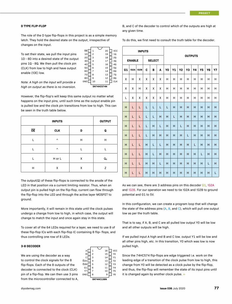
D TYPE FLIP-FLOP
The role of the D type flip-flops in this project is as a simple memory latch. They hold the desired state on the output, irrespective of changes on the input.
To set their state, we pull the input pins 1D - 8D into a desired state of the output pins 1Q - 8Q. We then pull the clock pin (CLK) from low to high and have output enable (!OE) low.
Note: A high on the input will provide a high on output as there is no inversion.
However, the flip-flop’s will keep this same output no matter what happens on the input pins, until such time as the output enable pin is pulled low and the clock pin transitions from low to high. This can be seen in the truth table below.
INPUTS OUTPUT
OE CLK D Q
L ^ H H
L ^ L L
L H or L X Q0
H X X Z
The output(Q) of these flip-flops is connected to the anode of the LED in that position via a current limiting resistor. Thus, when an output pin is pulled high on the flip-flop, current can flow through the flip-flop into the LED and through the active layer MOSFET to ground.
More importantly, it will remain in this state until the clock pulses undergo a change from low to high, in which case, the output will change to match the input and once again stay in this state.
To cover all of the 64 LEDs required for a layer, we need to use 8 of these flip-flop ICs with each flip-flop IC containing 8 flip- flops, and thus controlling one row of 8 LEDs.
3-8 DECODER
We are using the decoder as a way to control the clock signals for the 8 flip-flops. Each of the 8 outputs of the decoder is connected to the clock (CLK) pin of a flip-flop. We can then use 3 pins from the microcontroller connected to A,
2D3D4D5D6D7D8D
GND
1DOE
345678910
21
1817161514131211
1920
2Q3Q4Q5Q6Q7Q8QCLK
1QVCC
SN74HC574N
CG2AG2B
G1Y7
GND
BA
345678
21
1413121110
9
1516
Y1Y2Y3Y4Y5Y6
Y0VCC
SN74HC138N
B, and C of the decoder to control which of the outputs are high at any given time.
To do this, we first need to consult the truth table for the decoder.
INPUTSOUTPUTS
ENABLE SELECT
G1 !G2A !G2B C B A Y0 Y1 Y2 Y3 Y4 Y5 Y6 Y7
X H X X X X H H H H H H H H
X X H X X X H H H H H H H H
L X X X X X H H H H H H H H
H L L L L L L H H H H H H H
H L L L L H H L H H H H H H
H L L L H L H H L H H H H H
H L L L H H H H H L H H H H
H L L H L L H H H H L H H H
H L L H L H H H H H H L H H
H L L H H L H H H H H H L H
H L L H H H H H H H H H H L
As we can see, there are 3 address pins on this decoder G1, !G2A and !G2B. For our operation we need to tie !G2A and !G2B to ground potential and G1 to 5V.
In this configuration, we can create a program loop that will change the state of the address pins (A, B, and C), which will pull one output low as per the truth table.
That is to say, if A, B, and C are all pulled low output Y0 will be low and all other outputs will be high.
If we pulled input A high and B and C low. output Y1 will be low and all other pins high, etc. In this transition, Y0 which was low is now pulled high.
Since the 74HC574 flip-flops are edge triggered i.e. work on the leading edge of a transition of the clock pulse from low to high, this change from Y0 will be detected as a clock pulse by the flip-flop, and thus, the flip-flop will remember the state of its input pins until it is changed again by another clock pulse. ››
77Issue 036 July 2020diyodemag.com
PROJECT
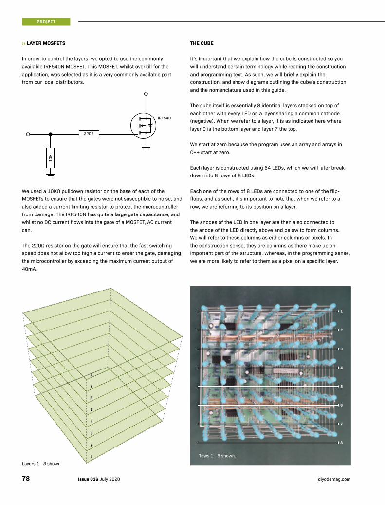
››LAYER MOSFETS
In order to control the layers, we opted to use the commonly available IRF540N MOSFET. This MOSFET, whilst overkill for the application, was selected as it is a very commonly available part from our local distributors.
We used a 10KΩ pulldown resistor on the base of each of the MOSFETs to ensure that the gates were not susceptible to noise, and also added a current limiting resistor to protect the microcontroller from damage. The IRF540N has quite a large gate capacitance, and whilst no DC current flows into the gate of a MOSFET, AC current can.
The 220Ω resistor on the gate will ensure that the fast switching speed does not allow too high a current to enter the gate, damaging the microcontroller by exceeding the maximum current output of 40mA.
10K
220R
IRF540
THE CUBE
It’s important that we explain how the cube is constructed so you will understand certain terminology while reading the construction and programming text. As such, we will briefly explain the construction, and show diagrams outlining the cube’s construction and the nomenclature used in this guide.
The cube itself is essentially 8 identical layers stacked on top of each other with every LED on a layer sharing a common cathode (negative). When we refer to a layer, it is as indicated here where layer 0 is the bottom layer and layer 7 the top.
We start at zero because the program uses an array and arrays in C++ start at zero.
Each layer is constructed using 64 LEDs, which we will later break down into 8 rows of 8 LEDs.
Each one of the rows of 8 LEDs are connected to one of the flip-flops, and as such, it’s important to note that when we refer to a row, we are referring to its position on a layer.
The anodes of the LED in one layer are then also connected to the anode of the LED directly above and below to form columns. We will refer to these columns as either columns or pixels. In the construction sense, they are columns as there make up an important part of the structure. Whereas, in the programming sense, we are more likely to refer to them as a pixel on a specific layer.
1
8
7
6
5
4
3
2
1
2
3
4
5
6
7
8
Layers 1 - 8 shown.
Rows 1 - 8 shown.
Issue 036 July 2020 diyodemag.com78
PROJECT
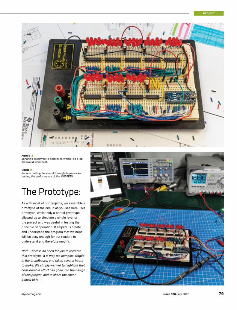
As with most of our projects, we assemble a prototype of the circuit as you see here. This prototype, whilst only a partial prototype, allowed us to simulate a single layer of the project and was useful in testing the principle of operation. It helped us create and understand the program that we hope will be easy enough for our readers to understand and therefore modify.
Note: There is no need for you to recreate this prototype. It is way too complex, fragile in the breadboard, and takes several hours to make. We simply wanted to highlight that considerable effort has gone into the design of this project, and to share the sheer beauty of it. ››
ABOVE ▲Johann's prototype to determine which Flip-Flop ICs would work best.
RIGHT ►Johann putting the circuit through its paces and testing the performance of the MOSFETS.
The Prototype:
79Issue 036 July 2020diyodemag.com
PROJECT
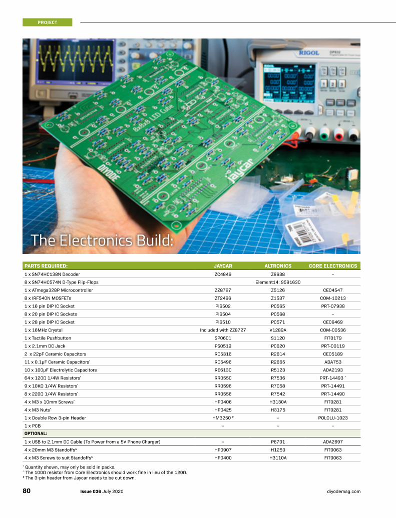
PARTS REQUIRED: JAYCAR ALTRONICS CORE ELECTRONICS1 x SN74HC138N Decoder ZC4846 Z8638 -
8 x SN74HC574N D-Type Flip-Flops Element14: 9591630
1 x ATmega328P Microcontroller ZZ8727 Z5126 CE04547
8 x IRF540N MOSFETs ZT2466 Z1537 COM-10213
1 x 16 pin DIP IC Socket PI6502 P0565 PRT-07938
8 x 20 pin DIP IC Sockets PI6504 P0568 -
1 x 28 pin DIP IC Socket PI6510 P0571 CE06469
1 x 16MHz Crystal Included with ZZ8727 V1289A COM-00536
1 x Tactile Pushbutton SP0601 S1120 FIT0179
1 x 2.1mm DC Jack PS0519 P0620 PRT-00119
2 x 22pF Ceramic Capacitors RC5316 R2814 CE05189
11 x 0.1µF Ceramic Capacitors* RC5496 R2865 ADA753
10 x 100µF Electrolytic Capacitors RE6130 R5123 ADA2193
64 x 120Ω 1/4W Resistors* RR0550 R7536 PRT-14493 ^
9 x 10KΩ 1/4W Resistors* RR0596 R7058 PRT-14491
8 x 220Ω 1/4W Resistors* RR0556 R7542 PRT-14490
4 x M3 x 10mm Screws* HP0406 H3130A FIT0281
4 x M3 Nuts* HP0425 H3175 FIT0281
1 x Double Row 3-pin Header HM3250 # - POLOLU-1023
1 x PCB - - -OPTIONAL:
1 x USB to 2.1mm DC Cable (To Power from a 5V Phone Charger) - P6701 ADA2697
4 x 20mm M3 Standoffs* HP0907 H1250 FIT0063
4 x M3 Screws to suit Standoffs* HP0400 H3110A FIT0063
* Quantity shown, may only be sold in packs.^ The 100Ω resistor from Core Electronics should work fine in lieu of the 120Ω.# The 3-pin header from Jaycar needs to be cut down.
The Electronics Build:
Issue 036 July 2020 diyodemag.com80
PROJECT

››PCB KEY
This key is very useful for troubleshooting. Once you have installed the components it can be near impossible to see the values printed underneath. Thus, it's incredibly difficult to discover a component installed incorrectly. Having a key like this allows you to systematically check the component in a location without needing to remove it.
Note: The PCB shown here is revision D. There may be some slight modifications to the final design which will be available as a kit from Jaycar and the parts list in this article. The parts list is correct however, the values printed on the PCB shown in this article may not be.
Assembling the project isn’t a complex task, however, there are some steps that need to be followed in a specific order. As such, we have opted to show the step-by-step build process, which we took to construct and test the project.
Naturally, the first step was populating the PCB with the necessary components. For this, we generally start with the low-profile components such as the resistors and work our way up to the biggest, which are the electrolytic capacitors. ››
PART IDENTIFIER VALUE QTY DESCRIPTION
Q1 16MHz 1 CRYSTAL
J1 Centre Positive 1 DC POWER JACK
ICSP Programming header 1 PIN HEADER
C1, C7, C8, C11, C12, C15, C16, C19, C20, C21, C23 0.1uF 11 CAPACITOR, European symbol
C2, C5, C6, C9, C10, C13, C14, C17, C18, C22 100uF 10 POLARISED CAPACITOR, European symbol
R65, R67, R69, R71, R73, R75, R77, R79, R81 10K 9 RESISTOR, European symbol
R1 - R64 120R 64 RESISTOR, European symbol
R66, R68, R70, R72, R74, R76, R78, R80 220R 8 RESISTOR, European symbol
C3, C4 22pF 2 CAPACITOR, European symbol
U1 328P 1 Atmel 328P Microcontroller
Q2, Q3, Q4, Q5, Q6, Q7, Q8, Q9 IRF540 8 HEXFET Power MOSFET
JP1 SMD Jumper 1 Normally open solder jumper
S1 MOMENTARY-SWITCH-SPST 1 Momentary Switch (Pushbutton) - SPST
U2 SN74HC138N 1 3 line to 8-line decoders demultiplexers
U3 - U10 SN74HC574N 8 OCTAL EDGE-TRIGGERED D-TYPE FLIP-FLOPS
Top side of the PCB. Note that not all of the ICs face the same direction.
81Issue 036 July 2020diyodemag.com
PROJECT
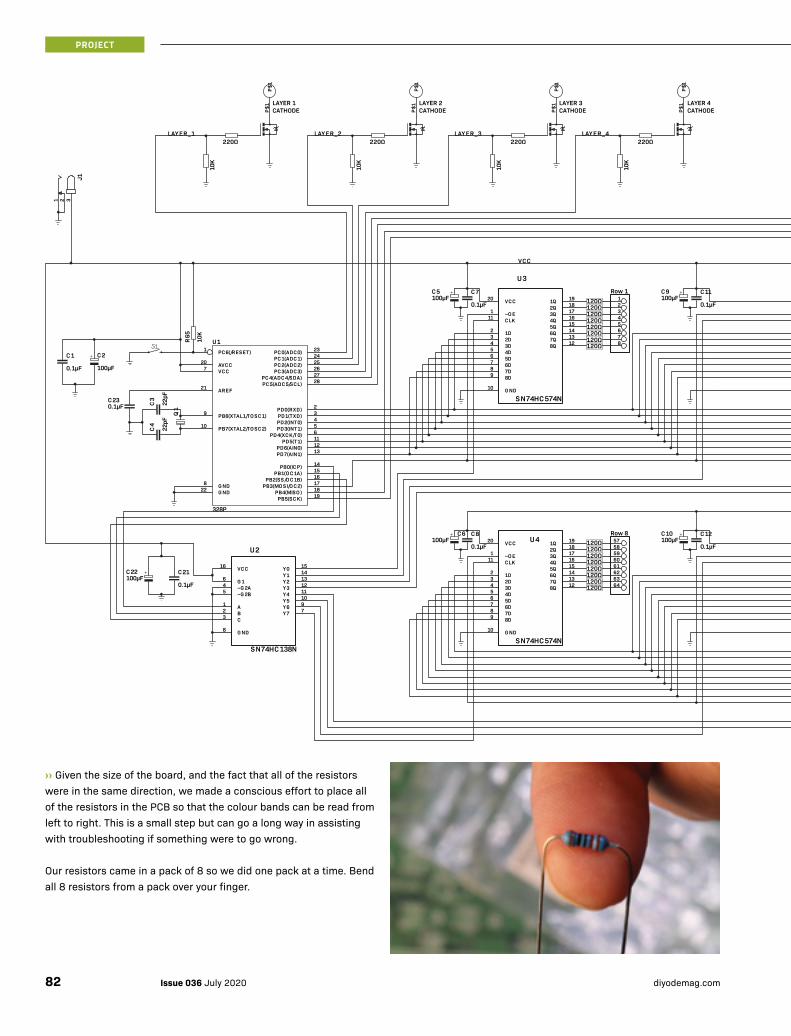
328P
22pF
22pF
0.1µF 100µF
SN74HC574N
SN74HC138N
0.1µF100µF
SN74HC574N
0.1µF100µF
SN74HC574N
0.1µF100µF
SN74HC574N
0.1µF100µuF
SN74HC574N
0.1µF100µF
SN74HC574N
0.1µF100µF
SN74HC574N
0.1µF100µF
SN74HC574N
0.1µF100µF
0.1µF100µF
0.1µF
10K
10K
10K
10K
10K
10K
10K
10K
10K
PB5(SCK) 19
PB7(XTAL2/TO SC2)10
PB6(XTAL1/TO SC1)9
G ND8
G ND22
VCC7
AREF21
AVCC20
PB4(MISO ) 18PB3(MO SI/O C2) 17PB2(SS/O C1B) 16PB1(O C1A) 15PB0(ICP) 14
PD7(AIN1) 13PD6(AIN0) 12PD5(T1) 11PD4(XCK/T0) 6PD3(INT1) 5PD2(INT0) 4PD1(TXD) 3PD0(RXD) 2
PC5(ADC5/SCL) 28PC4(ADC4/SDA) 27PC3(ADC3) 26PC2(ADC2) 25PC1(ADC1) 24PC0(ADC0) 23PC6(/RESET)1U1
Q1
C4
C3
C1 C2
VCC20
~O E1
CLK11
1D2
2D3
3D4
4D5
5D6
6D7
7D8
8D9
G ND10
1Q 19
2Q 18
3Q 17
4Q 16
5Q 15
6Q 14
7Q 13
8Q 12
U3
VCC16
G 16
~G 2A4
~G 2B5
A1
B2
C3
G ND8
Y0 15
Y1 14
Y2 13
Y3 12
Y4 11
Y5 10
Y6 9
Y7 7
U2
C7C5VCC20
~O E1
CLK11
1D2
2D3
3D4
4D5
5D6
6D7
7D8
8D9
G ND10
1Q 19
2Q 18
3Q 17
4Q 16
5Q 15
6Q 14
7Q 13
8Q 12
U5
C11C9VCC20
~O E1
CLK11
1D2
2D3
3D4
4D5
5D6
6D7
7D8
8D9
G ND10
1Q 19
2Q 18
3Q 17
4Q 16
5Q 15
6Q 14
7Q 13
8Q 12
U7
C15C13VCC20
~O E1
CLK11
1D2
2D3
3D4
4D5
5D6
6D7
7D8
8D9
G ND10
1Q 19
2Q 18
3Q 17
4Q 16
5Q 15
6Q 14
7Q 13
8Q 12
U9
C19C17
VCC20
~O E1
CLK11
1D2
2D3
3D4
4D5
5D6
6D7
7D8
8D9
G ND10
1Q 19
2Q 18
3Q 17
4Q 16
5Q 15
6Q 14
7Q 13
8Q 12
U4C8C6
VCC20
~O E1
CLK11
1D2
2D3
3D4
4D5
5D6
6D7
7D8
8D9
G ND10
1Q 19
2Q 18
3Q 17
4Q 16
5Q 15
6Q 14
7Q 13
8Q 12
U6C12C10
VCC20
~O E1
CLK11
1D2
2D3
3D4
4D5
5D6
6D7
7D8
8D9
G ND10
1Q 19
2Q 18
3Q 17
4Q 16
5Q 15
6Q 14
7Q 13
8Q 12
U8C16C14
VCC20
~O E1
CLK11
1D2
2D3
3D4
4D5
5D6
6D7
7D8
8D9
G ND10
1Q 19
2Q 18
3Q 17
4Q 16
5Q 15
6Q 14
7Q 13
8Q 12
U10C20C18
C21C22
C23
P$1
P$1
P$1
P$1
P$1
P$1
P$1
P$1
P$1
P$1
P$1
P$1
P$1
P$1
P$1
P$1
321
J1
1Row 1
2345678
9Row 2
10111213141516R
65
17Row 3
18192021222324
25Row 4
26272829303132
33Row 5
34353637383940
41Row 6
42434445464748
49Row 7
50515253545556
57Row 8
58596061626364
LAYER_1 LAYER_2
VCC
LAYER 8 CATHODE
LAYER 7 CATHODE
LAYER 6 CATHODE
LAYER 5 CATHODE
LAYER 4 CATHODE
LAYER 3 CATHODE
LAYER 2 CATHODE
LAYER 1 CATHODE
220Ω 220Ω 220Ω 220Ω 220Ω 220Ω 220Ω 220ΩLAYER_3 LAYER_4 LAYER_5 LAYER_6 LAYER_7 LAYER_8
+
+ + + +
+ + + +
+
120Ω120Ω120Ω120Ω120Ω120Ω120Ω120Ω
120Ω120Ω120Ω120Ω120Ω120Ω120Ω120Ω
120Ω120Ω120Ω120Ω120Ω120Ω120Ω120Ω
120Ω120Ω120Ω120Ω120Ω120Ω120Ω120Ω
120Ω120Ω120Ω120Ω120Ω120Ω120Ω120Ω
120Ω120Ω120Ω120Ω120Ω120Ω120Ω120Ω
120Ω120Ω120Ω120Ω120Ω120Ω120Ω120Ω
120Ω120Ω120Ω120Ω120Ω120Ω120Ω120Ω
››Given the size of the board, and the fact that all of the resistors were in the same direction, we made a conscious effort to place all of the resistors in the PCB so that the colour bands can be read from left to right. This is a small step but can go a long way in assisting with troubleshooting if something were to go wrong.
Our resistors came in a pack of 8 so we did one pack at a time. Bend all 8 resistors from a pack over your finger.
Issue 036 July 2020 diyodemag.com82
PROJECT
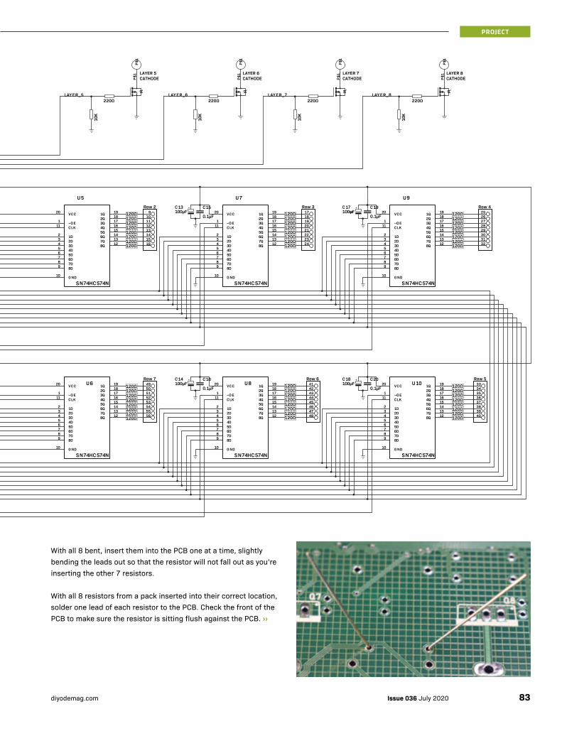
328P
22pF
22pF
0.1µF 100µF
SN74HC574N
SN74HC138N
0.1µF100µF
SN74HC574N
0.1µF100µF
SN74HC574N
0.1µF100µF
SN74HC574N
0.1µF100µuF
SN74HC574N
0.1µF100µF
SN74HC574N
0.1µF100µF
SN74HC574N
0.1µF100µF
SN74HC574N
0.1µF100µF
0.1µF100µF
0.1µF
10K
10K
10K
10K
10K
10K
10K
10K
10K
PB5(SCK) 19
PB7(XTAL2/TO SC2)10
PB6(XTAL1/TO SC1)9
G ND8
G ND22
VCC7
AREF21
AVCC20
PB4(MISO ) 18PB3(MO SI/O C2) 17PB2(SS/O C1B) 16PB1(O C1A) 15PB0(ICP) 14
PD7(AIN1) 13PD6(AIN0) 12PD5(T1) 11PD4(XCK/T0) 6PD3(INT1) 5PD2(INT0) 4PD1(TXD) 3PD0(RXD) 2
PC5(ADC5/SCL) 28PC4(ADC4/SDA) 27PC3(ADC3) 26PC2(ADC2) 25PC1(ADC1) 24PC0(ADC0) 23PC6(/RESET)1U1
Q1
C4
C3
C1 C2
VCC20
~O E1
CLK11
1D2
2D3
3D4
4D5
5D6
6D7
7D8
8D9
G ND10
1Q 19
2Q 18
3Q 17
4Q 16
5Q 15
6Q 14
7Q 13
8Q 12
U3
VCC16
G 16
~G 2A4
~G 2B5
A1
B2
C3
G ND8
Y0 15
Y1 14
Y2 13
Y3 12
Y4 11
Y5 10
Y6 9
Y7 7
U2
C7C5VCC20
~O E1
CLK11
1D2
2D3
3D4
4D5
5D6
6D7
7D8
8D9
G ND10
1Q 19
2Q 18
3Q 17
4Q 16
5Q 15
6Q 14
7Q 13
8Q 12
U5
C11C9VCC20
~O E1
CLK11
1D2
2D3
3D4
4D5
5D6
6D7
7D8
8D9
G ND10
1Q 19
2Q 18
3Q 17
4Q 16
5Q 15
6Q 14
7Q 13
8Q 12
U7
C15C13VCC20
~O E1
CLK11
1D2
2D3
3D4
4D5
5D6
6D7
7D8
8D9
G ND10
1Q 19
2Q 18
3Q 17
4Q 16
5Q 15
6Q 14
7Q 13
8Q 12
U9
C19C17
VCC20
~O E1
CLK11
1D2
2D3
3D4
4D5
5D6
6D7
7D8
8D9
G ND10
1Q 19
2Q 18
3Q 17
4Q 16
5Q 15
6Q 14
7Q 13
8Q 12
U4C8C6
VCC20
~O E1
CLK11
1D2
2D3
3D4
4D5
5D6
6D7
7D8
8D9
G ND10
1Q 19
2Q 18
3Q 17
4Q 16
5Q 15
6Q 14
7Q 13
8Q 12
U6C12C10
VCC20
~O E1
CLK11
1D2
2D3
3D4
4D5
5D6
6D7
7D8
8D9
G ND10
1Q 19
2Q 18
3Q 17
4Q 16
5Q 15
6Q 14
7Q 13
8Q 12
U8C16C14
VCC20
~O E1
CLK11
1D2
2D3
3D4
4D5
5D6
6D7
7D8
8D9
G ND10
1Q 19
2Q 18
3Q 17
4Q 16
5Q 15
6Q 14
7Q 13
8Q 12
U10C20C18
C21C22
C23
P$1
P$1
P$1
P$1
P$1
P$1
P$1
P$1
P$1
P$1
P$1
P$1
P$1
P$1
P$1
P$1
321
J1
1Row 1
2345678
9Row 2
10111213141516R
65
17Row 3
18192021222324
25Row 4
26272829303132
33Row 5
34353637383940
41Row 6
42434445464748
49Row 7
50515253545556
57Row 8
58596061626364
LAYER_1 LAYER_2
VCC
LAYER 8 CATHODE
LAYER 7 CATHODE
LAYER 6 CATHODE
LAYER 5 CATHODE
LAYER 4 CATHODE
LAYER 3 CATHODE
LAYER 2 CATHODE
LAYER 1 CATHODE
220Ω 220Ω 220Ω 220Ω 220Ω 220Ω 220Ω 220ΩLAYER_3 LAYER_4 LAYER_5 LAYER_6 LAYER_7 LAYER_8
+
+ + + +
+ + + +
+
120Ω120Ω120Ω120Ω120Ω120Ω120Ω120Ω
120Ω120Ω120Ω120Ω120Ω120Ω120Ω120Ω
120Ω120Ω120Ω120Ω120Ω120Ω120Ω120Ω
120Ω120Ω120Ω120Ω120Ω120Ω120Ω120Ω
120Ω120Ω120Ω120Ω120Ω120Ω120Ω120Ω
120Ω120Ω120Ω120Ω120Ω120Ω120Ω120Ω
120Ω120Ω120Ω120Ω120Ω120Ω120Ω120Ω
120Ω120Ω120Ω120Ω120Ω120Ω120Ω120Ω
With all 8 bent, insert them into the PCB one at a time, slightly bending the leads out so that the resistor will not fall out as you’re inserting the other 7 resistors.
With all 8 resistors from a pack inserted into their correct location, solder one lead of each resistor to the PCB. Check the front of the PCB to make sure the resistor is sitting flush against the PCB. ››
83Issue 036 July 2020diyodemag.com
PROJECT
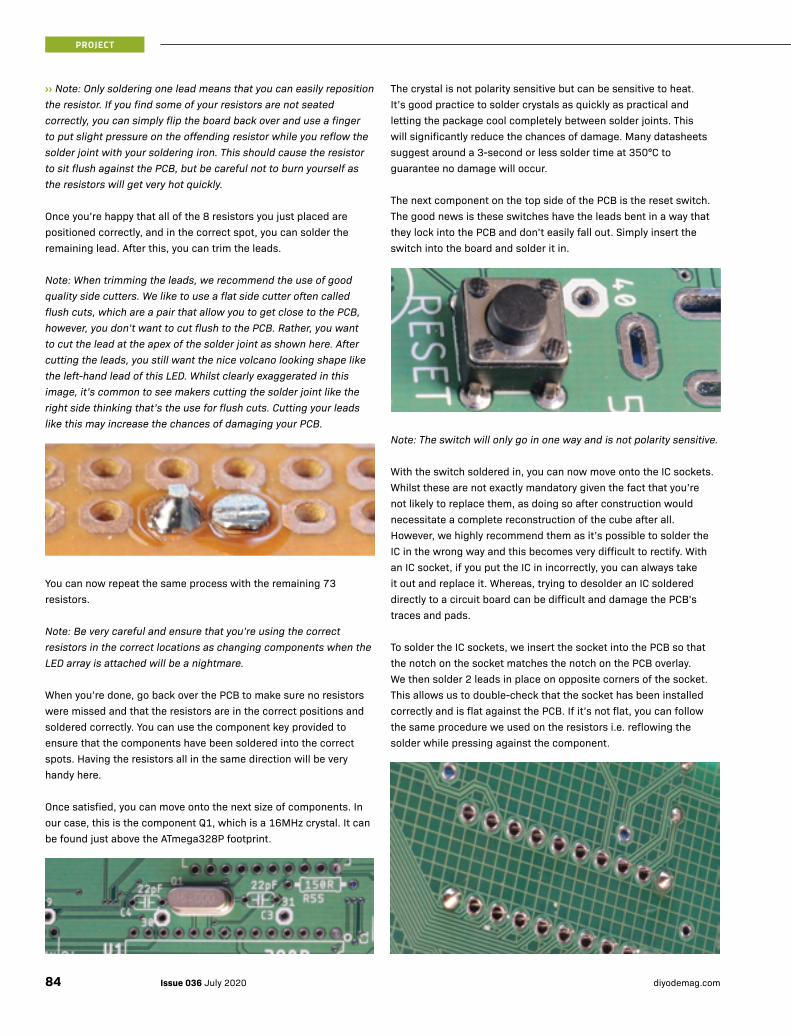
››Note: Only soldering one lead means that you can easily reposition the resistor. If you find some of your resistors are not seated correctly, you can simply flip the board back over and use a finger to put slight pressure on the offending resistor while you reflow the solder joint with your soldering iron. This should cause the resistor to sit flush against the PCB, but be careful not to burn yourself as the resistors will get very hot quickly.
Once you’re happy that all of the 8 resistors you just placed are positioned correctly, and in the correct spot, you can solder the remaining lead. After this, you can trim the leads.
Note: When trimming the leads, we recommend the use of good quality side cutters. We like to use a flat side cutter often called flush cuts, which are a pair that allow you to get close to the PCB, however, you don’t want to cut flush to the PCB. Rather, you want to cut the lead at the apex of the solder joint as shown here. After cutting the leads, you still want the nice volcano looking shape like the left-hand lead of this LED. Whilst clearly exaggerated in this image, it’s common to see makers cutting the solder joint like the right side thinking that’s the use for flush cuts. Cutting your leads like this may increase the chances of damaging your PCB.
You can now repeat the same process with the remaining 73 resistors.
Note: Be very careful and ensure that you’re using the correct resistors in the correct locations as changing components when the LED array is attached will be a nightmare.
When you’re done, go back over the PCB to make sure no resistors were missed and that the resistors are in the correct positions and soldered correctly. You can use the component key provided to ensure that the components have been soldered into the correct spots. Having the resistors all in the same direction will be very handy here.
Once satisfied, you can move onto the next size of components. In our case, this is the component Q1, which is a 16MHz crystal. It can be found just above the ATmega328P footprint.
The crystal is not polarity sensitive but can be sensitive to heat. It’s good practice to solder crystals as quickly as practical and letting the package cool completely between solder joints. This will significantly reduce the chances of damage. Many datasheets suggest around a 3-second or less solder time at 350°C to guarantee no damage will occur.
The next component on the top side of the PCB is the reset switch. The good news is these switches have the leads bent in a way that they lock into the PCB and don’t easily fall out. Simply insert the switch into the board and solder it in.
Note: The switch will only go in one way and is not polarity sensitive.
With the switch soldered in, you can now move onto the IC sockets. Whilst these are not exactly mandatory given the fact that you’re not likely to replace them, as doing so after construction would necessitate a complete reconstruction of the cube after all. However, we highly recommend them as it’s possible to solder the IC in the wrong way and this becomes very difficult to rectify. With an IC socket, if you put the IC in incorrectly, you can always take it out and replace it. Whereas, trying to desolder an IC soldered directly to a circuit board can be difficult and damage the PCB’s traces and pads.
To solder the IC sockets, we insert the socket into the PCB so that the notch on the socket matches the notch on the PCB overlay. We then solder 2 leads in place on opposite corners of the socket. This allows us to double-check that the socket has been installed correctly and is flat against the PCB. If it’s not flat, you can follow the same procedure we used on the resistors i.e. reflowing the solder while pressing against the component.
Issue 036 July 2020 diyodemag.com84
PROJECT
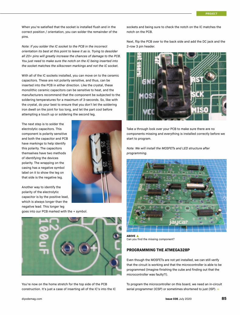
When you’re satisfied that the socket is installed flush and in the correct position / orientation, you can solder the remainder of the pins.
Note: If you solder the IC socket to the PCB in the incorrect orientation its best at this point to leave it as is. Trying to desolder all 20+ pins will greatly increase the chances of damage to the PCB. You just need to make sure the notch on the IC being inserted into the socket matches the silkscreen markings and not the IC socket.
With all of the IC sockets installed, you can move on to the ceramic capacitors. These are not polarity sensitive, and thus, can be inserted into the PCB in either direction. Like the crystal, these monolithic ceramic capacitors can be sensitive to heat, and the manufacturers recommend that the component be subjected to the soldering temperatures for a maximum of 3-seconds. So, like with the crystal, do your best to ensure that you don’t let the soldering iron dwell on the joint for too long, and let the part cool before attempting a touch up or soldering the second leg.
The next step is to solder the electrolytic capacitors. This component is polarity sensitive and both the capacitor and PCB have markings to help identify this polarity. The capacitors themselves have two methods of identifying the devices polarity. The wrapping on the casing has a negative symbol label on it to show the leg on that side is the negative leg.
Another way to identify the polarity of the electrolytic capacitor is by the positive lead, which is always longer than the negative lead. This longer leg goes into our PCB marked with the + symbol.
You’re now on the home stretch for the top side of the PCB construction. It’s just a case of inserting all of the IC’s into the IC
sockets and being sure to check the notch on the IC matches the notch on the PCB.
Next, flip the PCB over to the back side and add the DC jack and the 2-row 3 pin header.
Take a through look over your PCB to make sure there are no components missing and everything is installed correctly before we start to program.
Note: We will install the MOSFETs and LED structure after programming.
PROGRAMMING THE ATMEGA328P
Even though the MOSFETs are not yet installed, we can still verify that the circuit is working and that the microcontroller is able to be programmed (Imagine finishing the cube and finding out that the microcontroller was faulty?!).
To program the microcontroller on this board, we need an in-circuit serial programmer (ICSP) or sometimes shortened to just (ISP). ››
ABOVE ▲Can you find the missing component?
85Issue 036 July 2020diyodemag.com
PROJECT
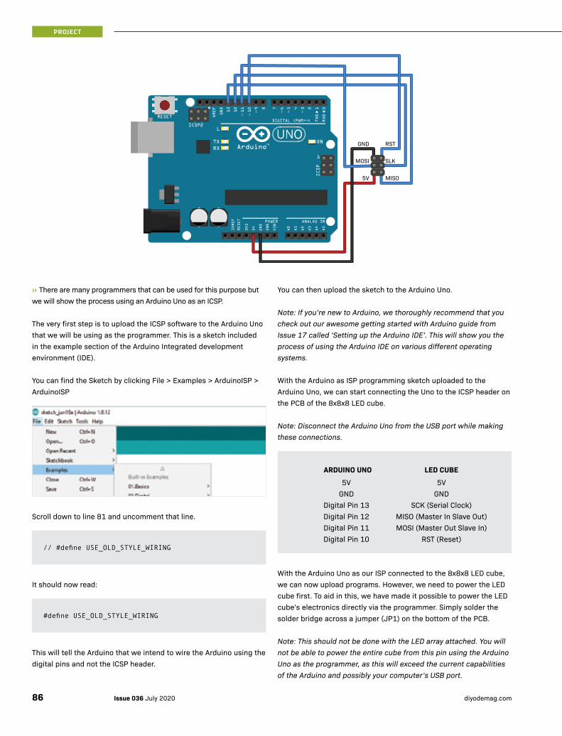
››There are many programmers that can be used for this purpose but we will show the process using an Arduino Uno as an ICSP.
The very first step is to upload the ICSP software to the Arduino Uno that we will be using as the programmer. This is a sketch included in the example section of the Arduino Integrated development environment (IDE).
You can find the Sketch by clicking File > Examples > ArduinoISP > ArduinoISP
Scroll down to line 81 and uncomment that line.
It should now read:
This will tell the Arduino that we intend to wire the Arduino using the digital pins and not the ICSP header.
// #define USE_OLD_STYLE_WIRING
#define USE_OLD_STYLE_WIRING
You can then upload the sketch to the Arduino Uno.
Note: If you’re new to Arduino, we thoroughly recommend that you check out our awesome getting started with Arduino guide from Issue 17 called ‘Setting up the Arduino IDE’. This will show you the process of using the Arduino IDE on various different operating systems.
With the Arduino as ISP programming sketch uploaded to the Arduino Uno, we can start connecting the Uno to the ICSP header on the PCB of the 8x8x8 LED cube.
Note: Disconnect the Arduino Uno from the USB port while making these connections.
With the Arduino Uno as our ISP connected to the 8x8x8 LED cube, we can now upload programs. However, we need to power the LED cube first. To aid in this, we have made it possible to power the LED cube’s electronics directly via the programmer. Simply solder the solder bridge across a jumper (JP1) on the bottom of the PCB.
Note: This should not be done with the LED array attached. You will not be able to power the entire cube from this pin using the Arduino Uno as the programmer, as this will exceed the current capabilities of the Arduino and possibly your computer’s USB port.
ARDUINO UNO LED CUBE5V 5V
GND GNDDigital Pin 13 SCK (Serial Clock)Digital Pin 12 MISO (Master In Slave Out)Digital Pin 11 MOSI (Master Out Slave In)Digital Pin 10 RST (Reset)
GND
MOSI
5V
RST
SLK
MISO
Issue 036 July 2020 diyodemag.com86
PROJECT
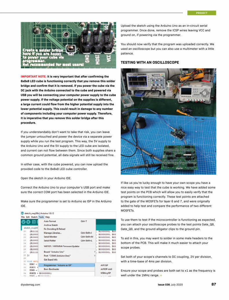
IMPORTANT NOTE: It is very important that after confirming the 8x8x8 LED cube is functioning correctly that you remove this solder bridge and confirm that it is removed. If you power the cube via the DC jack with the Arduino connected to the cube and powered via USB you will be connecting your computer power supply to the cube power supply. If the voltage potential on the supplies is different, a large current could flow from the higher potential supply into the lower potential supply. This could result in damage to any number of components including your computer power supply. Therefore, It is imperative that you remove this solder bridge after this procedure.
If you understandably don’t want to take that risk, you can leave the jumper untouched and power the device via a separate power supply while you run the test program. This way, the 5V supply to the Arduino Uno and the 5V supply to the LED cube are isolated, and current can not flow between them. Since both supplies share a common ground potential, all data signals will still be received fine.
In either case, with the cube powered, you can now upload the provided code to the 8x8x8 LED cube controller.
Open the sketch in your Arduino IDE.
Connect the Arduino Uno to your computer’s USB port and make sure the correct COM port has been selected in the Arduino IDE.
Make sure the programmer is set to Arduino as ISP in the Arduino IDE.
Upload the sketch using the Arduino Uno as an in-circuit serial programmer. Once done, remove the ICSP wires leaving VCC and ground on, if powering via the programmer.
You should now verify that the program was uploaded correctly. We used an oscilloscope but you can also use a multimeter with a little patience.
TESTING WITH AN OSCILLOSCOPE
If like us you’re lucky enough to have your own scope you have a nice easy way to test that the cube is working. We have added some test points on the PCB which will allow you to easily verify that the program is functioning correctly. These test points are attached to the gate of the MOSFETs for layer 6 and 7, and were originally added to help test and compare the performance of two different MOSFETs.
To use them to test if the microcontroller is functioning as expected, you can attach your oscilloscope probes to the test points Gate_Q8, Gate_Q9, and the ground alligator clips to the ground pin.
To aid in this, you may want to solder in some male headers to the bottom of the PCB. This will make it much easier to attach your scope probes.
Set both of your scope’s channels to DC coupling, 2V per division, with a time-base of 4ms per division.
Ensure your scope and probes are both set to x1 as the frequency is well under the 1MHz range. ››
87Issue 036 July 2020diyodemag.com
PROJECT
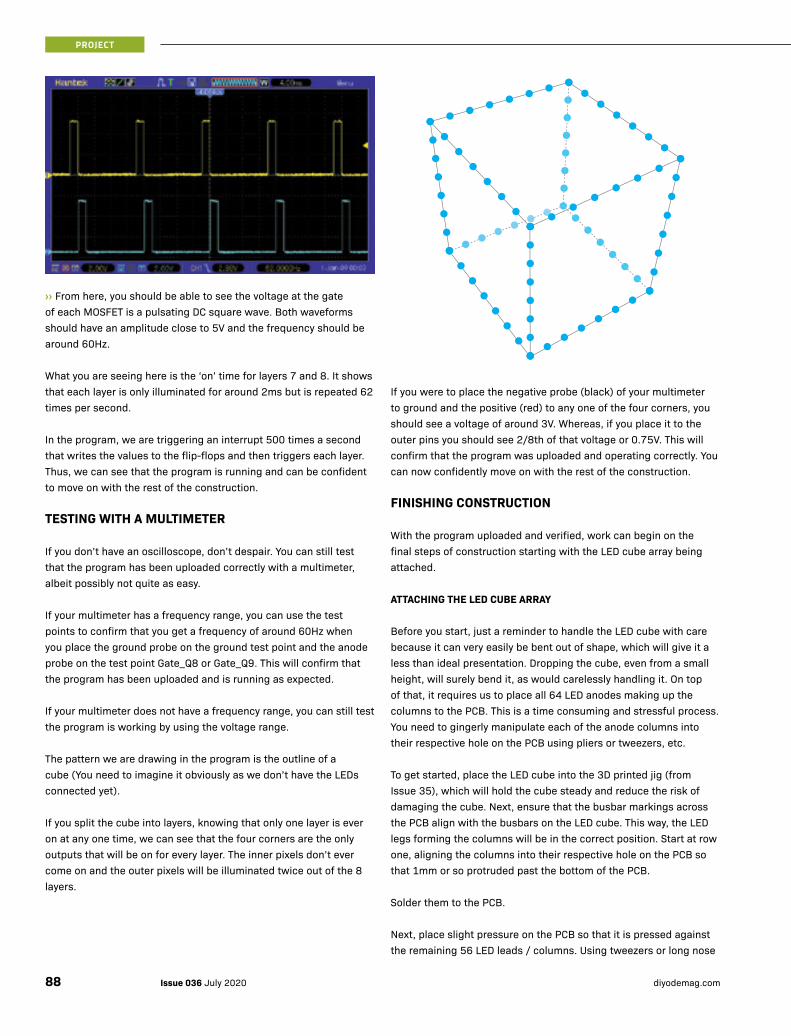
››From here, you should be able to see the voltage at the gate of each MOSFET is a pulsating DC square wave. Both waveforms should have an amplitude close to 5V and the frequency should be around 60Hz.
What you are seeing here is the ‘on’ time for layers 7 and 8. It shows that each layer is only illuminated for around 2ms but is repeated 62 times per second.
In the program, we are triggering an interrupt 500 times a second that writes the values to the flip-flops and then triggers each layer. Thus, we can see that the program is running and can be confident to move on with the rest of the construction.
TESTING WITH A MULTIMETER
If you don’t have an oscilloscope, don’t despair. You can still test that the program has been uploaded correctly with a multimeter, albeit possibly not quite as easy.
If your multimeter has a frequency range, you can use the test points to confirm that you get a frequency of around 60Hz when you place the ground probe on the ground test point and the anode probe on the test point Gate_Q8 or Gate_Q9. This will confirm that the program has been uploaded and is running as expected.
If your multimeter does not have a frequency range, you can still test the program is working by using the voltage range.
The pattern we are drawing in the program is the outline of a cube (You need to imagine it obviously as we don’t have the LEDs connected yet).
If you split the cube into layers, knowing that only one layer is ever on at any one time, we can see that the four corners are the only outputs that will be on for every layer. The inner pixels don’t ever come on and the outer pixels will be illuminated twice out of the 8 layers.
If you were to place the negative probe (black) of your multimeter to ground and the positive (red) to any one of the four corners, you should see a voltage of around 3V. Whereas, if you place it to the outer pins you should see 2/8th of that voltage or 0.75V. This will confirm that the program was uploaded and operating correctly. You can now confidently move on with the rest of the construction.
FINISHING CONSTRUCTION
With the program uploaded and verified, work can begin on the final steps of construction starting with the LED cube array being attached.
ATTACHING THE LED CUBE ARRAY
Before you start, just a reminder to handle the LED cube with care because it can very easily be bent out of shape, which will give it a less than ideal presentation. Dropping the cube, even from a small height, will surely bend it, as would carelessly handling it. On top of that, it requires us to place all 64 LED anodes making up the columns to the PCB. This is a time consuming and stressful process. You need to gingerly manipulate each of the anode columns into their respective hole on the PCB using pliers or tweezers, etc.
To get started, place the LED cube into the 3D printed jig (from Issue 35), which will hold the cube steady and reduce the risk of damaging the cube. Next, ensure that the busbar markings across the PCB align with the busbars on the LED cube. This way, the LED legs forming the columns will be in the correct position. Start at row one, aligning the columns into their respective hole on the PCB so that 1mm or so protruded past the bottom of the PCB.
Solder them to the PCB.
Next, place slight pressure on the PCB so that it is pressed against the remaining 56 LED leads / columns. Using tweezers or long nose
Issue 036 July 2020 diyodemag.com88
PROJECT
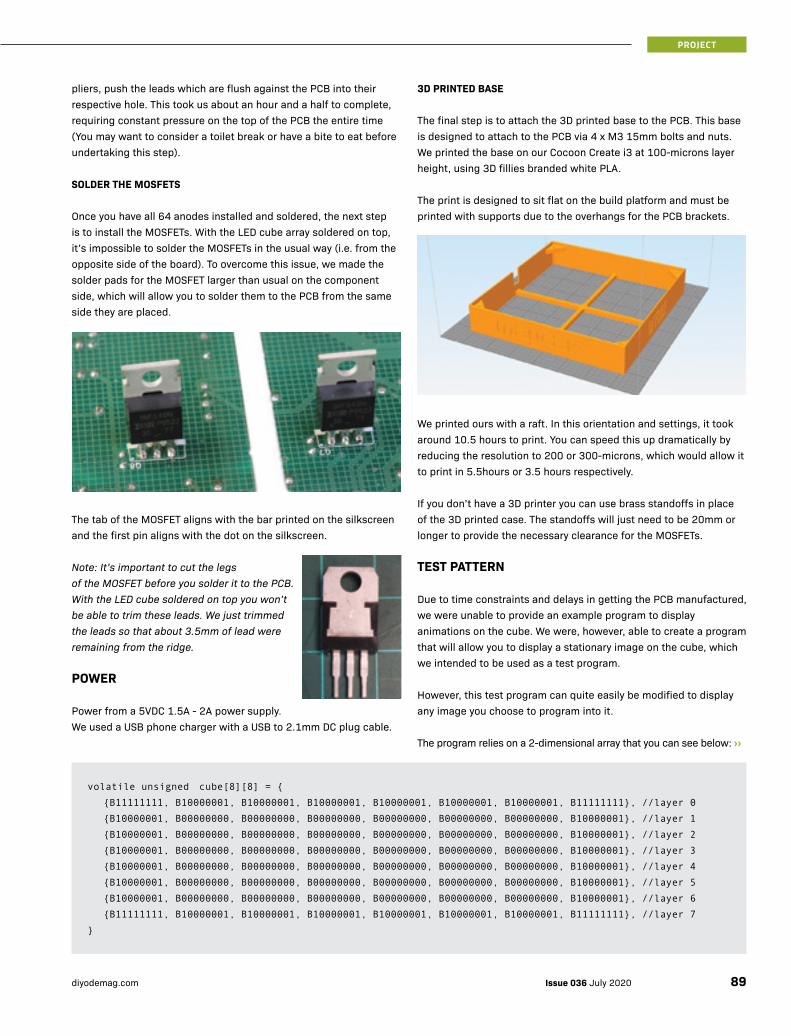
pliers, push the leads which are flush against the PCB into their respective hole. This took us about an hour and a half to complete, requiring constant pressure on the top of the PCB the entire time (You may want to consider a toilet break or have a bite to eat before undertaking this step).
SOLDER THE MOSFETS
Once you have all 64 anodes installed and soldered, the next step is to install the MOSFETs. With the LED cube array soldered on top, it’s impossible to solder the MOSFETs in the usual way (i.e. from the opposite side of the board). To overcome this issue, we made the solder pads for the MOSFET larger than usual on the component side, which will allow you to solder them to the PCB from the same side they are placed.
The tab of the MOSFET aligns with the bar printed on the silkscreen and the first pin aligns with the dot on the silkscreen.
Note: It’s important to cut the legs of the MOSFET before you solder it to the PCB. With the LED cube soldered on top you won’t be able to trim these leads. We just trimmed the leads so that about 3.5mm of lead were remaining from the ridge.
POWER
Power from a 5VDC 1.5A - 2A power supply. We used a USB phone charger with a USB to 2.1mm DC plug cable.
3D PRINTED BASE
The final step is to attach the 3D printed base to the PCB. This base is designed to attach to the PCB via 4 x M3 15mm bolts and nuts. We printed the base on our Cocoon Create i3 at 100-microns layer height, using 3D fillies branded white PLA.
The print is designed to sit flat on the build platform and must be printed with supports due to the overhangs for the PCB brackets.
We printed ours with a raft. In this orientation and settings, it took around 10.5 hours to print. You can speed this up dramatically by reducing the resolution to 200 or 300-microns, which would allow it to print in 5.5hours or 3.5 hours respectively.
If you don’t have a 3D printer you can use brass standoffs in place of the 3D printed case. The standoffs will just need to be 20mm or longer to provide the necessary clearance for the MOSFETs.
TEST PATTERN
Due to time constraints and delays in getting the PCB manufactured, we were unable to provide an example program to display animations on the cube. We were, however, able to create a program that will allow you to display a stationary image on the cube, which we intended to be used as a test program.
However, this test program can quite easily be modified to display any image you choose to program into it.
The program relies on a 2-dimensional array that you can see below: ››
volatile unsigned cube[8][8] = {
{B11111111, B10000001, B10000001, B10000001, B10000001, B10000001, B10000001, B11111111}, //layer 0
{B10000001, B00000000, B00000000, B00000000, B00000000, B00000000, B00000000, B10000001}, //layer 1
{B10000001, B00000000, B00000000, B00000000, B00000000, B00000000, B00000000, B10000001}, //layer 2
{B10000001, B00000000, B00000000, B00000000, B00000000, B00000000, B00000000, B10000001}, //layer 3
{B10000001, B00000000, B00000000, B00000000, B00000000, B00000000, B00000000, B10000001}, //layer 4
{B10000001, B00000000, B00000000, B00000000, B00000000, B00000000, B00000000, B10000001}, //layer 5
{B10000001, B00000000, B00000000, B00000000, B00000000, B00000000, B00000000, B10000001}, //layer 6
{B11111111, B10000001, B10000001, B10000001, B10000001, B10000001, B10000001, B11111111}, //layer 7
}
89Issue 036 July 2020diyodemag.com
PROJECT
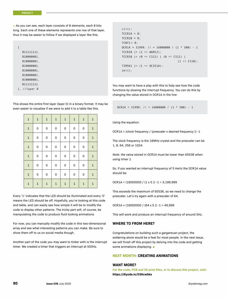
›› As you can see, each layer consists of 8 elements, each 8 bits long. Each one of these elements represents one row of that layer, thus it may be easier to follow if we displayed a layer like this.
This shows the entire first layer (layer 0) in a binary format. It may be even easier to visualise if we were to add it to a table like this.
1 1 1 1 1 1 1 1
1 0 0 0 0 0 0 1
1 0 0 0 0 0 0 1
1 0 0 0 0 0 0 1
1 0 0 0 0 0 0 1
1 0 0 0 0 0 0 1
1 0 0 0 0 0 0 1
1 1 1 1 1 1 1 1
Every ‘1’ indicates that the LED should be illuminated and every ‘0’ means the LED should be off. Hopefully, you’re looking at this code and table, and can easily see how simple it will be to modify the code to display other patterns. The tricky part will, of course, be manipulating the code to produce fluid looking animations.
For now, you can manually modify the code in this two-dimensional array and see what interesting patterns you can make. Be sure to show them off to us on social media though.
Another part of the code you may want to tinker with is the interrupt timer. We created a timer that triggers an interrupt at 500Hz.
{
B11111111,
B10000001,
B10000001,
B10000001,
B10000001,
B10000001,
B10000001,
B11111111
}, //layer 0You may want to have a play with this to help see how the code functions by slowing the interrupt frequency. You can do this by changing the value stored in OCR1A in the line:
Using the equation:
OCR1A = (clock frequency / (prescaler x desired frequency )) -1
The clock frequency is the 16MHz crystal and the prescaler can be 1, 8, 64, 256 or 1024.
Note: the value stored in OCR1A must be lower than 65536 when using timer 1.
So, if you wanted an interrupt frequency of 5 Hertz the OCR1A value should be:
OCR1A = (16000000 / (1 x 5 )) -1 = 3,199,999
This exceeds the maximum of 65536, so we need to change the prescaler. Let’s try again with a prescaler of 64.
OCR1A = (16000000 / (64 x 5 )) -1 = 49,999
This will work and produce an interrupt frequency of around 5Hz.
WHERE TO FROM HERE?
Congratulations on building such a gargantuan project, the soldering alone would be a feat for most people. In the next issue, we will finish off this project by delving into the code and getting some animations displaying. ■
NEXT MONTH: CREATING ANIMATIONS
WANT MORE?For the code, PCB and 3D print files, or to discuss this project, visit:https://diyode.io/036cwbkx
cli();
TCCR1A = 0;
TCCR1B = 0;
TCNT1 = 0;
OCR1A = 31999; // = 16000000 / (1 * 500) - 1
TCCR1B |= (1 << WGM12);
TCCR1B |= (0 << CS12) | (0 << CS11) |
(1 << CS10);
TIMSK1 |= (1 << OCIE1A);
sei();
OCR1A = 31999; // = 16000000 / (1 * 500) - 1
Issue 036 July 2020 diyodemag.com90
PROJECT
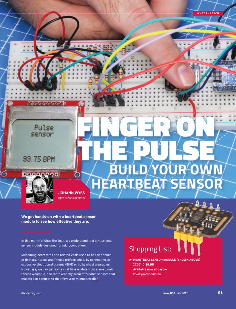
In this month’s What The Tech, we explore and test a Heartbeat sensor module designed for microcontrollers.
Measuring heart rates and related vitals used to be the domain of doctors, nurses and fitness professionals, by connecting up expensive electrocardiograms (EKG) or bulky chest wearables. Nowadays, we can get some vital fitness stats from a smartwatch, fitness wearable, and more recently, from affordable sensors that makers can connect to their favourite microcontroller. ››
FINGER ON FINGER ON THE PULSETHE PULSE
BUILD YOUR OWN BUILD YOUR OWN HEARTBEAT SENSORHEARTBEAT SENSOR
We get hands-on with a heartbeat sensor module to see how effective they are.
► HEARTBEAT SENSOR MODULE (SHOWN ABOVE) XC3740 $9.95 Available now at Jaycar www.jaycar.com.au
Shopping List:
JOHANN WYSSStaff Technical Writer
Issue 036 July 2020diyodemag.com 91
WHAT THE TECH
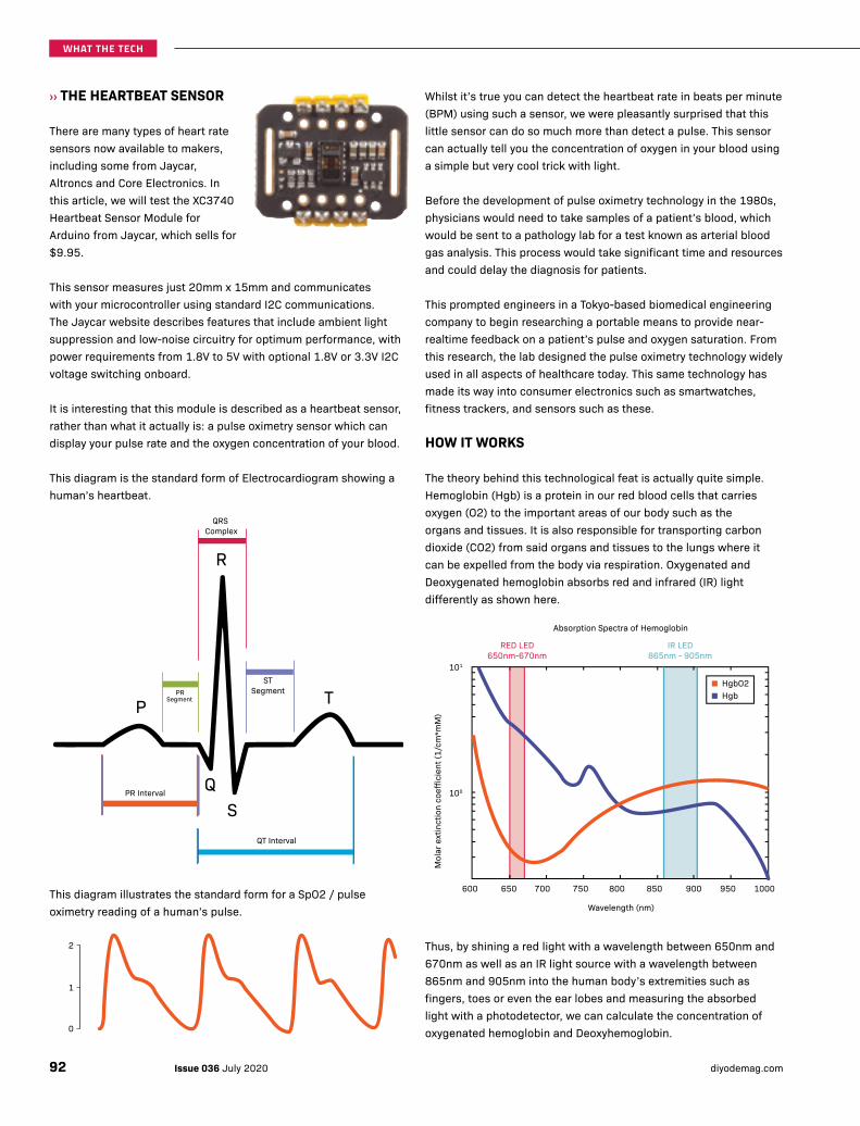
››THE HEARTBEAT SENSOR
There are many types of heart rate sensors now available to makers, including some from Jaycar, Altroncs and Core Electronics. In this article, we will test the XC3740 Heartbeat Sensor Module for Arduino from Jaycar, which sells for $9.95.
This sensor measures just 20mm x 15mm and communicates with your microcontroller using standard I2C communications. The Jaycar website describes features that include ambient light suppression and low-noise circuitry for optimum performance, with power requirements from 1.8V to 5V with optional 1.8V or 3.3V I2C voltage switching onboard.
It is interesting that this module is described as a heartbeat sensor, rather than what it actually is: a pulse oximetry sensor which can display your pulse rate and the oxygen concentration of your blood.
This diagram is the standard form of Electrocardiogram showing a human’s heartbeat.
This diagram illustrates the standard form for a SpO2 / pulse oximetry reading of a human’s pulse.
P
Q
R
S
TST
SegmentPRSegment
PR Interval
QT Interval
QRS Complex
0
1
2
Whilst it’s true you can detect the heartbeat rate in beats per minute (BPM) using such a sensor, we were pleasantly surprised that this little sensor can do so much more than detect a pulse. This sensor can actually tell you the concentration of oxygen in your blood using a simple but very cool trick with light.
Before the development of pulse oximetry technology in the 1980s, physicians would need to take samples of a patient’s blood, which would be sent to a pathology lab for a test known as arterial blood gas analysis. This process would take significant time and resources and could delay the diagnosis for patients.
This prompted engineers in a Tokyo-based biomedical engineering company to begin researching a portable means to provide near-realtime feedback on a patient’s pulse and oxygen saturation. From this research, the lab designed the pulse oximetry technology widely used in all aspects of healthcare today. This same technology has made its way into consumer electronics such as smartwatches, fitness trackers, and sensors such as these.
HOW IT WORKS
The theory behind this technological feat is actually quite simple. Hemoglobin (Hgb) is a protein in our red blood cells that carries oxygen (O2) to the important areas of our body such as the organs and tissues. It is also responsible for transporting carbon dioxide (CO2) from said organs and tissues to the lungs where it can be expelled from the body via respiration. Oxygenated and Deoxygenated hemoglobin absorbs red and infrared (IR) light differently as shown here.
Thus, by shining a red light with a wavelength between 650nm and 670nm as well as an IR light source with a wavelength between 865nm and 905nm into the human body’s extremities such as fingers, toes or even the ear lobes and measuring the absorbed light with a photodetector, we can calculate the concentration of oxygenated hemoglobin and Deoxyhemoglobin.
Absorption Spectra of Hemoglobin
HgbO2Hgb
Wavelength (nm)
600 650 700 750 800 850 900
RED LED650nm-670nm
IR LED865nm - 905nm
950 1000
Mol
ar e
xtin
ctio
n co
effic
ient
(1/c
m*m
M)
101
100
Issue 036 July 2020 diyodemag.com92
WHAT THE TECH
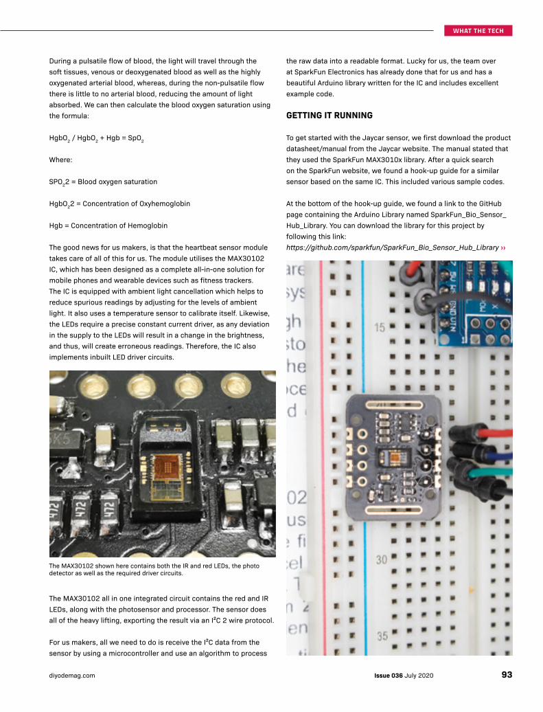
During a pulsatile flow of blood, the light will travel through the soft tissues, venous or deoxygenated blood as well as the highly oxygenated arterial blood, whereas, during the non-pulsatile flow there is little to no arterial blood, reducing the amount of light absorbed. We can then calculate the blood oxygen saturation using the formula:
HgbO2 / HgbO2 + Hgb = SpO2
Where:
SPO22 = Blood oxygen saturation
HgbO22 = Concentration of Oxyhemoglobin
Hgb = Concentration of Hemoglobin
The good news for us makers, is that the heartbeat sensor module takes care of all of this for us. The module utilises the MAX30102 IC, which has been designed as a complete all-in-one solution for mobile phones and wearable devices such as fitness trackers. The IC is equipped with ambient light cancellation which helps to reduce spurious readings by adjusting for the levels of ambient light. It also uses a temperature sensor to calibrate itself. Likewise, the LEDs require a precise constant current driver, as any deviation in the supply to the LEDs will result in a change in the brightness, and thus, will create erroneous readings. Therefore, the IC also implements inbuilt LED driver circuits.
The MAX30102 shown here contains both the IR and red LEDs, the photo detector as well as the required driver circuits.
The MAX30102 all in one integrated circuit contains the red and IR LEDs, along with the photosensor and processor. The sensor does all of the heavy lifting, exporting the result via an I²C 2 wire protocol.
For us makers, all we need to do is receive the I²C data from the sensor by using a microcontroller and use an algorithm to process
the raw data into a readable format. Lucky for us, the team over at SparkFun Electronics has already done that for us and has a beautiful Arduino library written for the IC and includes excellent example code.
GETTING IT RUNNING
To get started with the Jaycar sensor, we first download the product datasheet/manual from the Jaycar website. The manual stated that they used the SparkFun MAX3010x library. After a quick search on the SparkFun website, we found a hook-up guide for a similar sensor based on the same IC. This included various sample codes.
At the bottom of the hook-up guide, we found a link to the GitHub page containing the Arduino Library named SparkFun_Bio_Sensor_Hub_Library. You can download the library for this project by following this link: https://github.com/sparkfun/SparkFun_Bio_Sensor_Hub_Library ››
93Issue 036 July 2020diyodemag.com
WHAT THE TECH
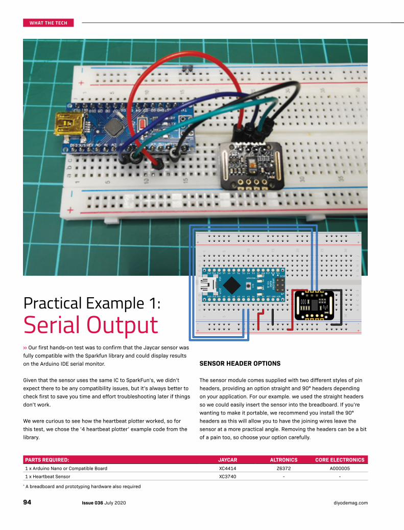
Practical Example 1: Serial Output››Our first hands-on test was to confirm that the Jaycar sensor was fully compatible with the Sparkfun library and could display results on the Arduino IDE serial monitor.
Given that the sensor uses the same IC to SparkFun’s, we didn’t expect there to be any compatibility issues, but it’s always better to check first to save you time and effort troubleshooting later if things don’t work.
We were curious to see how the heartbeat plotter worked, so for this test, we chose the ‘4 heartbeat plotter’ example code from the library.
PARTS REQUIRED: JAYCAR ALTRONICS CORE ELECTRONICS1 x Arduino Nano or Compatible Board XC4414 Z6372 A000005
1 x Heartbeat Sensor XC3740 - -
* A breadboard and prototyping hardware also required
SENSOR HEADER OPTIONS
The sensor module comes supplied with two different styles of pin headers, providing an option straight and 90° headers depending on your application. For our example. we used the straight headers so we could easily insert the sensor into the breadboard. If you’re wanting to make it portable, we recommend you install the 90° headers as this will allow you to have the joining wires leave the sensor at a more practical angle. Removing the headers can be a bit of a pain too, so choose your option carefully.
Issue 036 July 2020 diyodemag.com94
WHAT THE TECH

WIRING GUIDE
To replicate our example, all you need is an Arduino Nano or equivalent, the heartbeat sensor, a breadboard and jumper wires. Follow the Fritzing diagram or the following guide to wire up your prototype.
We only need to use the lower set of pins and do not use the top GND, RD, IRD or INT.
THE RESULTS
By uploading SparkFun’s example code to the Arduino Nano and using the serial plotter in the Arduino IDE, we can see a graph of the detected heartbeat.
In our case, the example is only showing the results from the IR sensor and not a combined IR and RED, and thus, it isn’t showing the entire combined pulse oximetry reading.
Usually, a pulse oximeter would use both LEDs to improve the sensitivity. Oxyhemoglobin absorbs infrared light and allows red light to pass through more freely while Deoxyhemoglobin absorbs red light and allows infrared light to pass through more freely. Thus, with this example, we are only seeing the level of absorption of the IR light. As the heart pumps we can see the surge of oxyhemoglobin absorbing more of the IR LED leaving less being reflected back to the photodetector.
This program only uses the IR LED as its only used to count pulses / heartbeats.
Considering that the sensor communicated successfully with our Nano and SparkFun library, we decided to move onto another experiment where we could display results on an LCD display. ››
SENSOR ARDUINO NANOVin 5VSDA A4SCL A5GND GND
95Issue 036 July 2020diyodemag.com
WHAT THE TECH
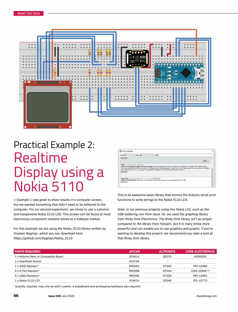
Practical Example 2: Realtime Display using a Nokia 5110››Example 1 was great to show results in a computer screen, but we wanted something that didn’t need to be tethered to the computer. For our second experiment, we chose to use a common and inexpensive Nokia 5110 LCD. This screen can be found at most electronics component retailers aimed at a hobbyist market.
For this example we are using the Nokia_5110 library written by Hossein Baghayi, which you can download here: https://github.com/baghayi/Nokia_5110
PARTS REQUIRED: JAYCAR ALTRONICS CORE ELECTRONICS1 x Arduino Nano or Compatible Board XC4414 Z6372 A000005
1 x Heartbeat Sensor XC3740 - -
1 x 330Ω Resistor* RR0560 R7040 PRT-14490
5 x 4.7kΩ Resistor* RR0588 R7054 COM-10969 **
5 x 10kΩ Resistors* RR0596 R7058 PRT-14491
1 x Nokia 5110 LCD XC4616 Z6348 RTL-10773
* Quantity required, may only be sold in packs. A breadboard and prototyping hardware also required.
This is an awesome basic library that mimics the Arduino serial print functions to write strings to the Nokia 5110 LCD.
Note: In our previous projects using this Nokia LCD, such as the USB soldering iron from issue 16, we used the graphing library from Rinky Dink Electronics. The Rinky Dink library isn’t as simple compared to the library from Hossein, but it is many times more powerful and can enable you to use graphics and graphs. If you’re wanting to develop this project, we recommend you take a look at that Rinky Dink library.
Issue 036 July 2020 diyodemag.com96
WHAT THE TECH
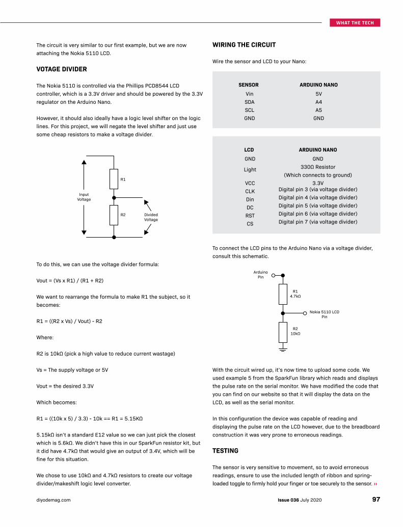
The circuit is very similar to our first example, but we are now attaching the Nokia 5110 LCD.
VOTAGE DIVIDER
The Nokia 5110 is controlled via the Phillips PCD8544 LCD controller, which is a 3.3V driver and should be powered by the 3.3V regulator on the Arduino Nano.
However, it should also ideally have a logic level shifter on the logic lines. For this project, we will negate the level shifter and just use some cheap resistors to make a voltage divider.
To do this, we can use the voltage divider formula:
Vout = (Vs x R1) / (R1 + R2)
We want to rearrange the formula to make R1 the subject, so it becomes:
R1 = ((R2 x Vs) / Vout) - R2
Where:
R2 is 10kΩ (pick a high value to reduce current wastage)
Vs = The supply voltage or 5V
Vout = the desired 3.3V
Which becomes:
R1 = ((10k x 5) / 3.3) - 10k == R1 = 5.15KΩ
5.15kΩ isn’t a standard E12 value so we can just pick the closest which is 5.6kΩ. We didn’t have this in our SparkFun resistor kit, but it did have 4.7kΩ that would give an output of 3.4V, which will be fine for this situation.
We chose to use 10kΩ and 4.7kΩ resistors to create our voltage divider/makeshift logic level converter.
InputVoltage
R1
R2 DividedVoltage
WIRING THE CIRCUIT
Wire the sensor and LCD to your Nano:
To connect the LCD pins to the Arduino Nano via a voltage divider, consult this schematic.
With the circuit wired up, it’s now time to upload some code. We used example 5 from the SparkFun library which reads and displays the pulse rate on the serial monitor. We have modified the code that you can find on our website so that it will display the data on the LCD, as well as the serial monitor.
In this configuration the device was capable of reading and displaying the pulse rate on the LCD however, due to the breadboard construction it was very prone to erroneous readings.
TESTING
The sensor is very sensitive to movement, so to avoid erroneous readings, ensure to use the included length of ribbon and spring-loaded toggle to firmly hold your finger or toe securely to the sensor. ››
ArduinoPin
R14.7kΩ
R210kΩ
Nokia 5110 LCDPin
SENSOR ARDUINO NANOVin 5VSDA A4SCL A5GND GND
LCD ARDUINO NANOGND GND
Light 330Ω Resistor (Which connects to ground)
VCC 3.3VCLK Digital pin 3 (via voltage divider)
Din Digital pin 4 (via voltage divider)
DC Digital pin 5 (via voltage divider)
RST Digital pin 6 (via voltage divider)
CS Digital pin 7 (via voltage divider)
97Issue 036 July 2020diyodemag.com
WHAT THE TECH
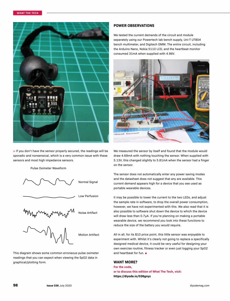
››If you don’t have the sensor properly secured, the readings will be sporadic and nonsensical, which is a very common issue with these sensors and most high impedance sensors.
This diagram shows some common erroneous pulse oximeter readings that you can expect when viewing the SpO2 data in graphical/plotting form.
Normal Signal
Pulse Oximeter Waveform
Low Perfusion
Noise Artifact
Motion Artifact
POWER OBSERVATIONS
We tested the current demands of the circuit and module separately using our Powertech lab bench supply, Uni-T UT804 bench multimeter, and Digitech DMM. The entire circuit, including the Arduino Nano, Nokia 5110 LCD, and the heartbeat monitor consumed 31mA when supplied with 4.96V.
We measured the sensor by itself and found that the module would draw 4.69mA with nothing touching the sensor. When supplied with 5.13V, this changed slightly to 5.81mA when the sensor had a finger on the sensor.
The sensor does not automatically enter any power saving modes and the datasheet does not suggest that any are available. This current demand appears high for a device that you see used as portable wearable devices.
It may be possible to lower the current to the two LEDs, and adjust the sample rate in software, to drop the overall power consumption, however, we have not experimented with this. We also read that it is also possible to software shut down the device to which the device will draw less than 0.7μA. If you’re planning on making a portable wearable device, we recommend you look into these functions to reduce the size of the battery you would require.
All in all, for its $10 price point, this little sensor was enjoyable to experiment with. Whilst it’s clearly not going to replace a specifically designed medical device, it could be very useful for designing your own exercise routine, fitness tracker or even just logging your SpO2 and heartbeat for fun. ■
WANT MORE?For the code, or to discuss this edition of What The Tech, visit:https://diyode.io/036gnyz
Issue 036 July 2020 diyodemag.com98
WHAT THE TECH