lume (lunar mission for exploration): a new asi proposal for lunar exploration and in situ resource...
TRANSCRIPT
American Institute of Aeronautics and Astronautics
1
LUME (LUnar Mission for Exploration): A New ASI Proposal for Lunar Exploration and In Situ Resource
Utilization
B. Ancarola1 Università degli studi di Napoli “Federico II”, Napoli, 80125, Italy
R. Armellin2 Politecnico di Milano, Milano,20156 , Italy
M. Attolico3 Politecnico di Milano, Milano 20156, Italy
A. Calamida4 Università degli Studi di Roma Tor Vergata, Roma, 00040, Italy
A. Davighi5 Politecnico di Milano, Milano, 20156, Italy
G. Filacchione6 INAF-IASF, Roma, 00133, Italy
U. Tancredi7 Seconda Università degli Studi diNapoli, Aversa, (CE), 81031, Italy
and
M. Toller8 Università degli Studi di Udine, Udine, 33100, Italy
A novel ASI Lunar mission is here proposed by a task force of Ph.D. students. After 14th January 2004 president G.W Bush’s speech, a new input to space human exploration has been given. The Moon, thanks to nearness to Earth, is identified as an important test bed for all future human missions. The task force LUME mission has been designed to fit with Italian technological capabilities leaving it open anyway for international cooperation. Three main module are foreseen: a lunar low altitude polar orbiter, a lander near the “peak of the eternal light” and a rover. The polar orbiter is equipped with a complete suite of experiments for remote sensing observation (high resolution color camera, VIS-NIR imaging spectrometer, neutron and X spectrometers and SAR radar). This will provide a lunar surface map in high spatial resolution at different wavelengths: the orbiter payload will be used both to refine the selection of the landing site and to support the rover navigation. The lander will reach the region of “peak of the eternal light”, located in the South Pole–Aitken
1 Ph.D. student, Università degli studi di Napoli “Federico II”, Napoli, 80125, Italy 2 Ph.D. student, Aerospace Engineering Department, Via La Masa 34, 20156, Milano . 3 Ph.D. student, Aerospace Engineering Department, Via La Masa 34, 20156, Milano 4 Ph.D. student, INAF-Osservatorio Astronomico di Roma, Via Frascati 33, 00040 Monte Porzio Catone (RM), Italy 5 Ph.D. student, Aerospace Engineering Department, Via La Masa 34, 20156, Milano 6 Researcher, INAF-IASF Istituto Nazionale di Astrofisica, Istituto di Astrofisica Spaziale e Fisica Cosmica, via del Fosso del Cavaliere, 100, 00133, Roma. 7 Ph.D. Student, Department of Aerospace and Mechanical Engineering, E-Mail: [email protected]. 8 Post-Doc, DPMSC Dipartimento di Patologia e Medicina Sperimentale e Clinica, Piazzale Kolbe 4, 33100 Udine

American Institute of Aeronautics and Astronautics
2
Basin. This landing site has been selected for two main reasons: a) sun-light is always available to deliver the power useful to perform lander experiments and b) some easy-reachable and interesting craters are close to this region. The lander embark a sun powered ISRU plant to demonstrate O2 extraction from lunar (ilmenite) soil and a robotic arm that can pick up lunar samples both from the soil and the rover. The nuclear powered rover is equipped with a drill system that, in the first phase of its mission, will deliver samples to be processed by the ISRU plant. In a second phase the rover will move to “de Gerlache” crater, identified as an attractive region to search for water ice. The rover drill includes an imaging VIS-NIR spectrometer dedicated to analyze the mineral composition and the water ice presence along the walls of the excavated hole. Both the orbiter and the lander will carry as payload two aquatic enclosed ecosystems (biospheres): these systems have been chosen as the best trade off between reduced requirements and easy data comprehension to evaluate space environment effects on life.
1. Introduction HIS paper will concern about the description of an exploratory mission to the Moon, proposed by a group of Italian PH.D. students in Planetary Sciences, Astronomy, Space Engineering and Biology. The Italian Space
Agency (ASI) has selected this group of people to take part in the Space Exploration’s Task Force1, promoted by NASA for its new long term space-project. The main purposes of the NASA long term space plan is to allow the human return to the Moon, though the mission is also aimed to validate concepts for human exploration of Mars. Innovative technologies are explicitly required by NASA to pursue this aim, and should be developed in a sustainable and affordable manner. This is the starting point to propose a new and alternative mission to Moon.
The main purpose of this mission is to confirm the presence of water-ice in the permanent shadowed areas of the Moon South Pole and to deliver a lunar oxygen demonstration device (ISRU) on the surface of our satellite, to prove that the technology is feasible. Other achievement are to evaluate the impact of Moon environment and space conditions on a tested and standardized Earth life-model and to retrieve accurate data about the chemical composition of the surface and sub-surface (~1-2km) of the Moon. To accomplish these objectives we are in need of an orbiter and a lander + rover. Scientific instruments have been added to both components of the spacecraft as mass margins allowed to increase the scientific return of the mission.
2. Lunar scientific background The Italian participation to the Moon exploration is lead by the following reasons: • lunar based Geology and Astronomy will provide new insights into our Solar System; • development of advanced space technologies; • construction of a permanent manned lunar base, using a technology that will be of strategic importance for
future exploration missions towards Mars; • extraction of local resources (water, He3, oxygen).
This paper will describe a possible mission scenario, consisting in an orbiter, lander and rover, devoted to the research of the more promising regions of the Moon, best suited to set up a manned lunar base and to experiment some advanced technological issues.
3. Lunar Scientific Objectives The prime scientific objectives of a lunar orbiter are the global characterization of the surface and sub-surface:
the future exploration and exploitation of the lunar environment requires a detailed knowledge of the mineral’s distribution and resources (ice, volatiles) of our satellite. The morphological characterization of the surface (maria, highlands, craters) will be of valuable help to choose an optimal site to establish future manned bases.
The main scientific motivations to further more explore the Moon with an advanced orbiter and rover are: • Earth and Moon formation and evolution in the primordial solar system; the Moon possesses a
differentiated crust and an ancient surface bearing witness to accretional processes, well preserved since the first hundred million years thanks to the absence of atmospheric processes, while they have been erased
T

American Institute of Aeronautics and Astronautics
3
from Earth surface; • the relative accessibility of the Moon makes it an advantageous station for future exploration (i.e. Mars)
and laboratory for experimental test grounds (biospheres and ISRU test-beds); • the lunar paradox is that due to Apollo and Luna missions we have samples measurements from only few
landing sites near the equator and we are unable to extend this results to the whole lunar surface; • the Moon is interesting for a comparative analysis and study of the planetary processes due to internal and
external phenomena (tectonics, igneous and mafic activity, impact processes, regolith formation); • necessity to acquire adequate topographic and gravimetric data sets for the whole satellite; • study of the dichotomy between Moon’s visible side (maria and highlands) and invisible side (highlands); • necessity of a global coverage with high spatial and spectral resolution for derivation of mineralogical and
elemental composition; • realization of a digital elevation model (DEM) of the entire lunar surface to correct images for local
illumination conditions and to study morphology and formation processes; • investigation of the lunar subsurface structure through magnetometer and radar to detect magnetic
anomalies and structures.
A. Ice on the Moon The idea that ice and other trapped volatiles could exist in permanently shadowed regions near the lunar poles
was proposed by Watson, Murray and Brown (1961). The only possible way for ice to exist on the Moon is in a permanently shadowed area. The Clementine imaging
experiment showed that such permanently shadowed areas do exist at the bottom of deep craters near the South Pole of the Moon. It appears, actually, that approximately 6000 to 15000 km2 of the area around the South Pole is permanently shadowed.
The permanently shadowed area near the North Pole appears on Clementine to be considerably less, but the lunar Prospector results show a much larger water bearing area at the North Pole. Much of the area around the South Pole is within the Aitken-Basin (see Fig. 1 ), a giant impact crater 2500 km in diameter and 12 km deep at its lowest point. Many smaller craters exist on the floor of this basin. Since they are down in this basin, the floors of many of these craters are never exposed to sunlight. Within these craters the temperatures would never rise above about 100 K 2. Any water ice at the bottom of the crater could probably exist for billions of years at these temperatures. Arnold 3 concludes, taking into account the stability of the location and orientation of the lunar poles and the different destructive mechanisms, that “cold traps” seem to have been in place for ~ 2·109 years. Four potential source of lunar H2O exist:
1) solar wind reduction of Fe in the regolith: the lunar soil contains metallic iron from two sources; there is a meteoritic component and a substantial quantity of fine-grained Fe which must be formed out of the lunar soil itself by the reduction:
2) OHFeHsilicatesFe 20
2)( +→+++ (1) 3) In highland soil there is ~0.4% by weight of this lunar Fe. In about 2·109 years the lunar soil has been reworked and exposed to a depth of the order of 2m 4 and the total H2O corresponding to the 0.4% of Fe0 is then ~ 0.5 g/cm2; this corresponds to a total of 1.9·1017g of H2O on the lunar surface (3.8·1017 cm2); 4) H2O-containing meteorites: the Moon's surface is continuously bombarded by meteorites and micrometeorites. Many of these “impactors” contain water ice, and the lunar craters show that many of these were very large objects. 5) The total amount of H2O liberated from this source should be 1016 g; 6) cometary’s impacts: comets are known to contain large amounts of H2O (mass ~1016 g) and an impact of a single comet could bring in an amount comparable to the two mechanisms described before; 7) degassing of the interior (least certain) that could supply an amount of trapped H2O estimated in the range of 1016-1017g.
B. What happens to ice on the Moon? Any ice which survived to impact would be scattered over the lunar surface. Most would be quickly vaporized
by sunlight and lost to space, but some would end up inside the permanently shadowed craters, either by directly

American Institute of Aeronautics and Astronautics
4
entering the crater or migrating over the surface as randomly moving individual molecules which would reach the craters and freeze there.
Once inside the crater, the ice would be relatively stable, so over time the ice would collect in these cold traps, and be buried to some extent by meteoritic gardening. However, two important destructive mechanisms have been also identified:
1) photodissociation of H2O molecules adsorbed on the sunlit surface; 2) sputtering or decomposition of trapped H2O by solar wind particles3.
C. Why is ice on the Moon important? The simple fact that the ice is there will help scientists constrain models of impacts on the lunar surface and the effects of meteorite gardening, photo-dissociation, and solar wind sputtering on the Moon. Beyond the scientifically intriguing aspects, deposits of ice on the Moon would have many practical aspects for future manned lunar exploration. There is no other source of water on the Moon, and shipping water to the Moon for use by humans would be extremely expensive ($2,000 to $20,000 per kg). The lunar water could also serve as a source of oxygen, another vital material not readily found on the Moon, and hydrogen, which could be used as rocket fuel. It appears that in addition to the permanently shadowed areas there are some higher areas such as crater rims which are permanently exposed to sunlight and could serve as a source of power for future missions.
Fig. 1 South pole Aitken Basin. Albedo, Topography iron and titanium distributions (image courtesy NASA).
4. Importance of lunar ISRU
In-Situ Resource Utilisation (ISRU) means “living off the land” and is a strategy to reduce the initial mass that has to be launched from Earth utilising the in-situ resources such as the production of propellant (In-Situ Propellant Production – ISPP) or the production of breathable gases, water or other goods needed by a human crew.
Past attempts at constructing a strategy to continue the human exploration of Moon and Mars have suffered from high projected costs of space transportation hardware development and production. To reduce these costs, an approach is proposed which is designed to take advantage of the utilization of resources and of propellant produced in-situ. This allows the associated spacecraft and launch vehicles to be less massive and complex than would otherwise be possible.
Much of the space community has focused on in-situ resource utilisation (ISRU) for either the Moon or Mars, and little work has been done in exploring possible commonalities between ISRU on the two destinations. Technologies successfully used in one place might be applied to the other: the Moon and Mars should not be regarded as isolated places, but as bases from which to explore the outer Solar System that can interact.
In both environments (the Moon and Mars), there is much geo-chemical information to be extracted from the surface, and the near sub-surface, which is valuable for advancing not only science, but also future ISRU and eventual human settlement efforts. The focus on utilization of this type of intangible yet, but valuable resources, is appropriate given the lesser mass and mission complexity needed to extract such information. In addition, robotic explorers can test and validate information about engineering processes desired for the extraction, production, processing, storage, and eventual utilization of fuels, water, and oxygen on a planetary surface (Moon or Mars).

American Institute of Aeronautics and Astronautics
5
A. Moon Resource Utilization
Nearly half the weight of lunar surface material is actually oxygen and many other resources that could be used by future space explorers are present on the Moon. A primary example is the lunar regolith. Tests on the Earth using this type of soil retrieved from the Moon reveal that significant amounts of oxygen could be extracted from the material by several different processes. Such in-situ produced oxygen could be used for Earth-return fuel oxidizer or for life support. Being able to produce needed resources on the Moon would reduce the amount of mass that would have to be launched from the Earth. Besides oxygen production, the Moon can also be the place to test concepts for habitat construction, radiation shielding and extraction of other indigenous materials.
Propellant availability at the mission destination has extremely high flight performance advantages; not only can the space vehicle avoid carrying the return propellant, but also the propellant required to transport the return propellant. For this reason oxygen extracted from the lunar regolith has long been recognized as potentially one of the most valuable resources on the Moon.
More recently, investigations have been concentrated on the reduction of ilmenite for producing Lunar Liquid Oxygen (LLOX). Ilmenite is an abundant mineral found in lunar regolith. One of the promising process concepts for lunar oxygen production is ilmenite reduction with hydrogen:
FeTiO3(s) + H2(g) = Fe(s) + TiO2(s) + H2O(g) (2) H2O(l) = H2(g) + ½O2(g) (electrolysis) (3) FeTiO3(s) = Fe(s) + TiO2(s) + ½O2(g) (4)
5. Mission description
A. Transfer and Insertion Trajectory The mission consists of a Moon polar orbit remote sensing spacecraft, a near South Pole lander, to perform an in
situ resource utilization, and a rover to search for water. Different strategies have been investigated to realize such kind of mission: direct transfer from LEO, transfer from GTO and weak stability boundary.
Due to weight and dimensions of the spacecraft, the sharing launcher fairing strategy which makes the GTO transfer appealing can’t be applied. The exploitation of weak stability boundary implies an overall mission complication and long transfer times without remarkable �v savings6. So a direct transfer from a LEO orbit strategy has been chosen.
The circular parking orbit is defined by the altitude, inclination and m Right Ascension of Ascending Node ( RAAN). A typical parking orbit has an altitude of 200 km and with an inclination equal to the latitude of the launcher’s site. Selecting a proper RAAN two launch opportunities per day, without using phasing orbit, are available if the launcher’s site altitude is greater than Moon. For a lunar mission a dusk/dawn arrival is preferred due to sun illumination conditions. This implies that only two launch windows per month can be used to give the selected lunar polar orbit.
The LTT is obtained by firing the launcher third stage at the optimal true anomaly that guarantees the right RAAN of the lunar polar orbit that matches the dusk/dawn condition (Fig.2).
A mid curse correction maneuver has to be planned to correct the possible LTT injection dispersion of the launcher. Near the LTT apoapsis the spacecraft enters the Moon sphere of influence and performs an hyperbolic passage with a periselenium altitude of 100 km. At the hyperbola periselenium the satellite main engines are fired to accomplish the circularization maneuver. This maneuver has been split into two burns to reduce gravity losses. The first burn injects the spacecraft in a high elliptic orbit of 5000 km of apoapsis then a second burn is accomplished at the elliptic orbit periselenium to obtain a polar circular orbit of 100 km of altitude (Fig.3) A small maneuver of 24 m/s is foreseen to obtain the final frozen orbit.
A code to compute the optimal transfer has been developed using analytical ephemeris and a SQP optimizer.

American Institute of Aeronautics and Astronautics
6
The following table resumes all the �v’s including an additional �v3 to obtain the final frozen orbit described in.
The total transfer time, including the maneuvers to acquire the final frozen orbit, is approximately 5.8 days.
B. Descent and Landing After being in orbit for three months a complete and accurate map of the landing site is available and the landing
maneuver can start. The lunar landing maneuver is organized as follows. Fist the lander is separated from the orbiter and injected
into a lower periselenium orbit thought an impulsive maneuver. The periselenium altitude must be greater than 20 km to avoid collision with lunar mountains. At the perigee an optimal continuous thrust maneuver starts which brings the spacecraft at the longitude and latitude of the selected landing site at safe vertical altitude of 2 km. The remaining part of the descending maneuver is performed on the vertical. The thrusters are cut off at an altitude of 2 m above the ground and the impact velocity is 3 m/s.
A dedicated software has been developed to optimize the descent and landing maneuver. It has been assumed to realize a planar continuous and variable thrust trajectory. The optimization is carried out using a SQP optimizer..
The maneuver is accomplished using 6 TR-312-100YN (Northrop –Grumman’s) engines. Each of these MMH/N2O4 engines supplies 559 N with an Isp=330 s.
Fig. 2 Lunar transfer Orbit
Fig. 3 Lunar orbit circularization
Table 1 �v’s review Parameter Description Value [m/s] �v1 LTT injection 3138 �v2 Polar orbit circularization 830 �v3 Frozen orbit achievement 24

American Institute of Aeronautics and Astronautics
7
The landing trajectory shown in Fig.4 is obtained with the thrust profile of Fig.5. It has to be remarked that the selected propulsion configuration guarantees a safe soft landing also with a single
engine failure. On the hypotheses of delivering a dry mass of 620 kg on the Moon south pole, the following parameters has been
computed:
A dispersion analysis on the landing point due to a random error on the spacecraft attitude control has been
performed. Considering a maximum error value of ±1° an error box of 14x12 km has been computed.
C. Orbiter description This mission to the Moon foresees a payload requiring coverage capability of Moon polar regions, designed to
operate for two years. This payload requirement limits the possible lunar orbit inclination values to a region centered in 90°, whose extension depends on the sensors steering capability.
Regarding the altitude above lunar surface, from a compromise between to sensors resolution and view are maximization, circular orbits with altitude values between 100 to 200 km are foreseen.
Other factors that impact the nominal orbit selection are longitude coverage (a repeated global Moon coverage is obviously desirable), Earth – Lunar Orbiter communication link availability, and Satellite – Sun direction, that affects the power source (solar arrays) design. There are families of quasi-circular lunar orbits with the property of being equilibrium solutions of the averaged two body problem perturbed by the non-spherical lunar gravity terms, known as frozen orbits15. For objects orbiting around the Moon there are solutions with polar inclination. The choice of a frozen orbit can, in principle, solve stability concerns on the 100 km orbits, enabling their selection and thus enhancing sensor resolution capability. Such an orbit, being inherently stable, will also reduce the station keeping fuel mass, that in this case would be devoted to restore the initial frozen conditions after a significant amount of perturbations have occurred. From the other side, these frozen orbits are very sensitive to the initial conditions, with slightly different orbital elements to the ones that do not provide frozen orbits. Therefore, an accurate station-keeping capability is requested. No study has been conducted to assess the necessary station keeping �V. Hence, the needed station keeping fuel for a non-frozen, circular 100 km polar orbit (~5% of the orbiter mass for a 2 years mission ) has been used as a conservative upper limit of the necessary station keeping fuel for the polar 100 km
Table 2 Landing optimal parameters Parameter Value Rp [km] 61357 � [°] 51.14 � [°] ~0 Tof [s] 1328 Mp [kg] 579
Fig. 4 Optimal landing trajectory (yellow) and orbiter trajectory during the landing phase (red)
Fig. 5 Thrust control profile during landing

American Institute of Aeronautics and Astronautics
8
frozen orbit.
1. Orbiter Scientific payload The orbiter scientific payload consists of
the instruments mentioned in Table 3, with the aim of studying the surface and sub-surface (~1-2 km) chemical composition of the Moon.
D. Lander description The lander will be supposed to reach the
Moon South Pole by means of a platform able to perform a soft landing over a geological and morphological interesting area.
It carries a significant number of instruments on board, to perform scientific and technological experiments. Data collected will be sent directly to the Earth from the surface through the Deep Space Network (DSN). The lander carries most of the propulsion subsystem on it and is equipped with a robotic arm for samples collections from both the Moon’s surface or from the drill system mounted on the rover.
2. Lander configuration The central block of the lander is the
nucleus (Fig.8) and contains the tanks for attitude and control thrusters, the scientific payload, a parabolic antenna to permit the
data-link towards the orbiter, the omni antenna for connection with the rover, the robotic arm able to collect surface minerals to be processed by the ISRU thanks to a dedicated camera and the solar sensor for spacecraft control during the landing phase (Fig. 6)
The upper ISRU platform rotates and maintains the mirror position in the direction of solar rays. This is possible
Fig. 6 The Robotic arm takes a sample from the rover Fig. 7 Rover deployment on Moon surface
Table 3 Orbiter scientific payload and description.
High Resolution Stereo Camera
(HRSC)
to provide a tri-dimensional global view in 4 spectral bands (Vis-NIR) of the surface of the Moon with a spatial resolution of about 2.5m@200 km. The camera will be used also to decide the best landing site and to support the navigation of the rover.
Visible Near Infrared Mapping Spectrometer
(VNIMS)
to identify minerals, ices and volatiles in the range 0.4-2.0 µm and to map the spatial distribution with a resolution of about 50 m.
X-Ray Fluorescence
Spectrometer (XRFS)
to map the distribution of the main elements (Si, Mg, Al, Na, Fe, Ca) with a spatial resolution of about 5-10 km. This instrument can operate in conditions of low illumination too (polar regions).
Slow Neutron Spectrometer
(SNS)
to detect thermal neutrons emitted by water-ice in the lunar polar regions
Synthetic Aperture Radar (SAR)
to be used as SAR to map large lunar regions and as radiometer to retrieve the surface temperature��

American Institute of Aeronautics and Astronautics
9
due to a motor step by step that is placed inside the top of the cylinder included in the lander. The rover is fixed on the ISRU superior plate, and is fixed through a connection to a robotic arm, that, after the
landing and the rotation of the superior plate (about 100°), releases the rover on the Moon surface (Fig 7). After the rover descent, the ISRU block plate rotates until a 70° configuration to place the mirror in a position suitable to reflect the solar rays in the direction of the furnace.
The arm includes a panoramic 360° rotating camera to image the landing site and the rover deployment. The third block of the lander contains the fuel and oxidizer tanks for the landing manoeuvre. Sized to
accommodate propulsion system needs, four spherical tanks (r = 27 cm) are required for the N2O4 and three others (r = 33 cm) for the MMH.
In order to meet the general scientific and technological requirements, the lander will be realized around a soft-descending module. After separation from the spacecraft, the lander will descend over the lunar South Pole region; thanks to a descending engine and lateral thrusters it will be possible to decelerate it and to land it gently onto the surface. During the descending phase, an integrated attitude and control landing system (laser altimeter and navigation camera) will perform the necessary trajectory manoeuvres and corrections.
The descending engines, thrusters and integrated landing system will be placed in the inferior cylinder shaped lander bus, containing the six legs too. This landing platform (similar to LEMs) guarantees high stability and a low baricentre position.
3. Lander Payloads The main payloads embarked on the Moon lander are: • biospheres; • ISRU demonstration plant for production of oxygen from ilmenite rich minerals; • colour cameras for observation; these cameras should be movable to allow a 360° view around the lander
and for a close inspection of nearby objects; • environmental detectors (soil temperature, seismographs, dielectric and magnetic probes)
The purpose of the Oxygen Production Demonstration Plant (O2 plant) is to test in-situ one or two processes of
oxygen production from lunar minerals in order to prove the possibility of large-scale production for a manned base (fuel and life support). Such ISRU plant will accomplishes its main task in several days, but the remainder of the instruments will continue to operate for several months.
The process selected for the experiments is based on the reduction of ilmenite at high temperature. Many research teams have already studied theoretical and experimental aspects of O2 production, and there are at
least 30 known processes. Other considerations are the following: • hydrogen would be imported from the Earth anyway for propellant for the main engines of manned
spacecraft; • the result of the reaction is H2O, which is easy to dissociate by electrolysis, and could be used for other
purposes. • the dissociated hydrogen will be recycled to be used as the reducing agent again; • ilmenite is the most abundant of the oxide minerals (up to 10 % in some Apollo samples). It provides the
biggest oxygen yield in any type of lunar mineral (soils, basalt or glass). •
The objectives of the O2 operation are:
������������
���� ������������
����
���������
����������� ������
��� �����
�������������
������������
���������
������� �����������
Fig. 8 Lander Nucleus
Fig. 9 Landing block

American Institute of Aeronautics and Astronautics
10
• to explore the surroundings of the Lander with a rover, then collect various samples of lunar soil and bring them back to the Lander;
• to treat the samples to obtain a suitable feedstock for the plant on board the Lander; • to process the feedstock to obtain O2 (or if power is limited, only an intermediate product, such as H2O or
CO2); • to measure with sensors the efficiency of the process (weight of O2 produced/weight of the sample), and
draw conclusions on the overall process by comparing the results with the ones obtained in laboratory; • if possible, to monitor the behaviour of the components of the plant, and check their resistivity to the lunar
environment. The rover is a key element to comply with the above mentioned objectives because it allows the choice of
several different samples, making results more representative and make it possible to collect them far from the Lander, thus avoiding the inconvenient of a possible contamination/modification of the soil due to the engines.
Small samples (range 10-1000 g) will be collected by the rover or from the robotic arm mounted on the Lander. The same arm takes the samples from the rover sample-analyser and puts them in the vessel of ISRU plant.
a) Production Plant
The process described by Williams16,17 is used but without utilizing a cell to electrolyse water. A flow of H2 is maintained over the heated sample (about 1000°C). H2O is removed from the flow during the process to avoid a recombination with the sample and is stored for measurement. H2 is re-injected into the furnace.
The plant is installed on a turn module mounted at the top of the lander. The purpose of this rotating device is to allow for the 1.5 m solar dish and the solar furnace in the focus to track together the sun.
The step-by-step sequence of events is the following: • the furnace is heated until sensors reach 1000°C; • the arm gets the sample of the lunar soil; • the sample is crushed, sieved and weighed (small conveyor belts carry the mineral from one device to
another); • the powder of samples is poured into a crucible; • the crucible is lifted and stuck against a seal, thus making a hermetic furnace, covered with a heat-
absorbing material; • the furnace is located on the focus of the solar dish, which is aimed towards the sun (diameter: 1.5 m); • the water production begins and lasts several hours; • the water produced is evaluated either by a drier or a spectrometer.
Based on Williams, the requirement for the plant and associated devices are :
E. Rover description After successful soft landing, a rover will be released on the Moon surface from the lander, by means of a
dedicated robotic arm. A preliminary mass and power budget has been performed at the actual configuration iteration, resulting in an
overall rover mass of 68 kg, with a power consumption ranging from 6 W in standby to maximum 37 W. The rover mission can be divided in two parts. In the first one the rover will conduct several expeditions around
the lander to collect some soil samples, using the onboard drill, for the ISRU process (that takes place on the lander
Table 4 Plant associated devices
Item Mass (kg) Power (W) Vessel + mirror 5 Solar Electrolysis Cell 5 <400
Pump 3.5 77 Sensors. 2 86 Tubing 1.5 -
Beneficiation 5 80 Conveyors 5 40
Miscellaneous (H2 tank, etc) 10 -

American Institute of Aeronautics and Astronautics
11
itself). In the second part of the mission, the rover reaches one of the Moon crater near the landing site (see paragraph F), goes down into the crater and, using the drill and the mass-spectrometer, analyzes the soil to find, if possible, water-ice.
For the first phase the rover needs a omni-antenna to interact with the lander and a collection-box to store the soil samples and carry them to the lander. In the second phase the rover moves for ~20 km in order to reach the crater base (see paragraph F). In this phase the rover can communicate only with the spacecraft using a high-gain antenna, therefore there are communication eclipses. The power system has to produce energy without the sunlight. Finally the drill has to be able to sample the interior of the crater to a depth of about 40 cm in search for water using the on board spectrometer.
The configuration, that meets all mission specifications, is shown in Fig.10 in both operative and stowed configuration.
4. Rover payload The rover will be equipped with: • one panoramic camera for navigation; • one disposable driller to penetrate lunar surface to a depth of about 0.5 m; • one spectrometer contained into the driller.
The proposed arm-drill-spectrometer integrated package has the key goal to study the lunar subsurface structure and more specifically:
• perform reflectance imaging spectroscopy in the visible and near-infrared (0.4-2.5 µm) range at different depths in order to search water ices and volatiles;
• evaluate the soil mechanical properties by utilising the force, torque and temperature information available from the drilling process;
The spectrometer is located on the drill rod to perform spectroscopy on images collected near the bottom of the borehole. The images are acquired through a sapphire window placed on the lateral wall of the drill tool as near as possible to the drill head and transported to the spectrometer by means of an optical fibre system. The system can acquire a whole ring image by using the drill rotational motion.
F. Landing site selection To comply with the mission objectives, we decided to select the area of the South Pole-Aitken Basin (SPA) as
our landing site. This area is potentially rich in volatile materials, including water in permanently shaded regions. There is also an area, known as “peak of eternal light” (a ridge between the rims of several craters), that receives sunlight nearly all the time. Landing in an area of nearly continual sunlight could help thermal control and power generation.
The “peak of eternal light” is therefore considered by P. J. Stooke the best landing target region5. In utilizing images taken by the U.S. Pentagon's Clementine spacecraft, in 1994, Stooke has actually tagged seven landing zones as areas from which a rover might have access to nearby permanently shaded terrains. The lunar South Pole region, as seen by Clementine, and a sketch with some possible landing sites and routes into perennial dark craters are
a) b)
Fig. 10 Rover Configuration: a) Operative and b)Stowed

American Institute of Aeronautics and Astronautics
12
shown in Fig. . The seven possible landing sites have been chosen
to provide the shortest reasonable routes to the nearby craters (between about 8 and 20 km), with reasonable slopes (mostly diagonal traverses of crater walls) and direct line of site communications with the Earth or the lander, or both. The knowledge of topography is extremely limited in these areas and so a detailed analysis of route safety and communications is not yet possible.
To best sample SPA rim material, sites have also been chosen positioned on the ejecta blankets of Shackleton and “de Gerlache” craters (which covers the whole 'peak'), and adjacent to small craters which should have excavated fresher material from under the local weathered lunar regolith. Sites generally facing Earth, not hidden behind local ridges, have been also chosen to maximize communication periods.
.In Stooke's view, sites 4 and 7 are probably the best for access to volatiles because of the size of the dark areas and the shallower slopes on the rover route. Site 7, for example, offers several pathways into “de Gerlache” crater, including a short direct track if the walls are shallow enough..
The SPA region has been selected as our landing region, in particular site number 7, for the shortest and shallowest route to the nearby shaded crater.
The landing site selection could change especially owing to the future results of Smart-1 mission, which will accurately search for water in the darker parts of the SPA Basin and will be mapping the region of the “peak of eternal light”.
6. Biospheres on the Moon In the perspective of a one-way Mission to an unfriendly environment without atmosphere and limited gravity as
Moon surface, the single remote opportunity in finding any kind of life form compatible with our current knowledge maybe lie in the analysis of those unique and safe micro-habitats in which eventually some elementary organic components could be developed and/or preserved. In this way of thinking resides our search of residual ice inside Moon’s craters.
Otherwise, always inside the field of life science in space, we could anyway take advantage from this kind of one-way mission to evaluate the impact of Moon environment and space conditions on a tested and standardized Earth life-model, if we are able to realize a system, not to much expensive in term of power supply, requirements and weight, capable to co-existing inside the payload together with other technological instruments. For this reasons, we propose to send an aquatic ecosystem on Moon Orbit within our spacecraft, suggesting the subsequent possibility of a Moon landing, if we are able to guarantee a quite “soft” landing followed by the maintenance of power supply for a long-term period (at least a couple of years) after landing.
Fig. 11 Seven landing sites on Moon South Pole (upper panel); rover path routes from landing sites to interesting nearby craters (lower panel). Images taken from (Stooke, LPI science conference XXXIV, 2003).
American Institute of Aeronautics and Astronautics
13
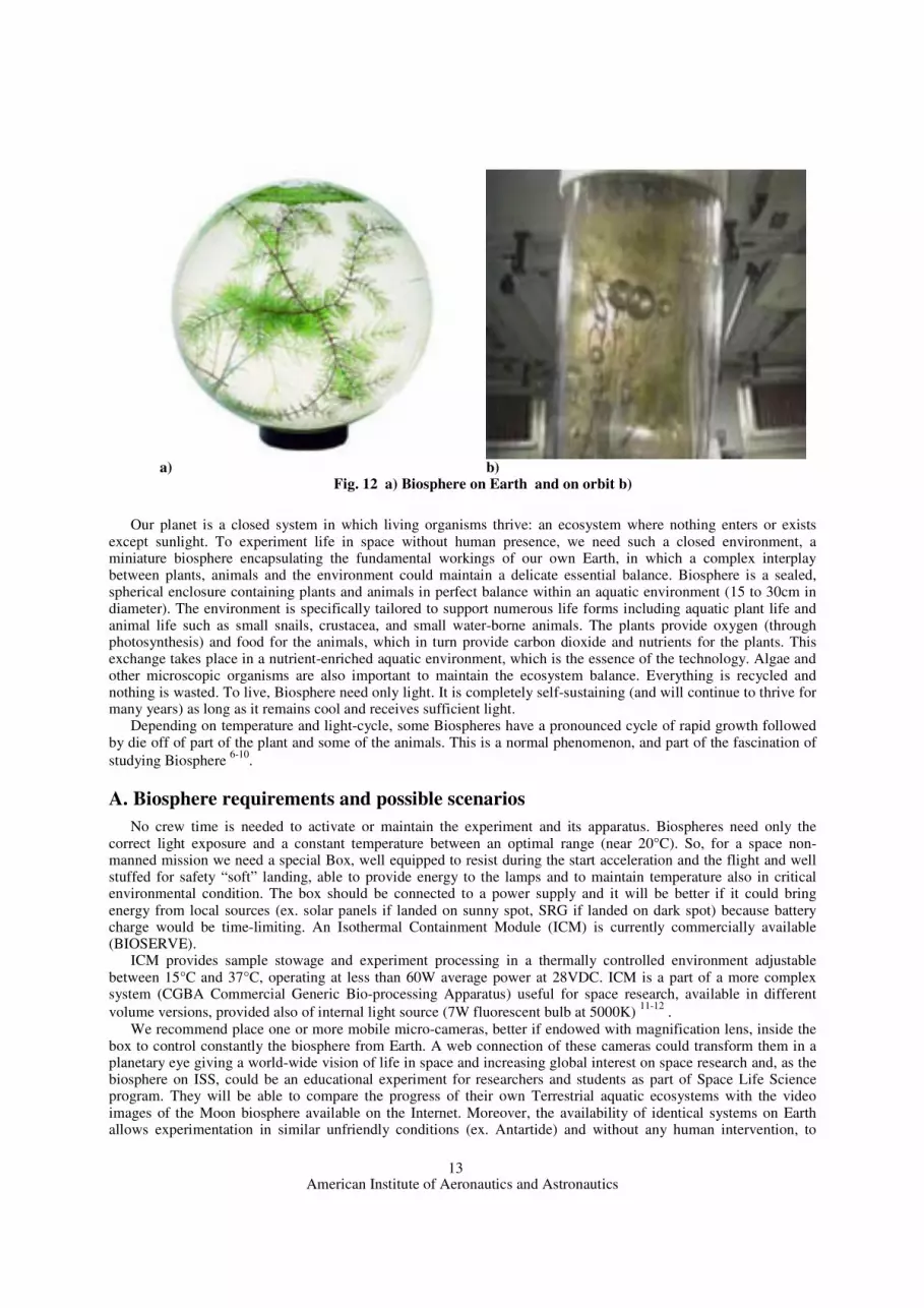
Our planet is a closed system in which living organisms thrive: an ecosystem where nothing enters or exists
except sunlight. To experiment life in space without human presence, we need such a closed environment, a miniature biosphere encapsulating the fundamental workings of our own Earth, in which a complex interplay between plants, animals and the environment could maintain a delicate essential balance. Biosphere is a sealed, spherical enclosure containing plants and animals in perfect balance within an aquatic environment (15 to 30cm in diameter). The environment is specifically tailored to support numerous life forms including aquatic plant life and animal life such as small snails, crustacea, and small water-borne animals. The plants provide oxygen (through photosynthesis) and food for the animals, which in turn provide carbon dioxide and nutrients for the plants. This exchange takes place in a nutrient-enriched aquatic environment, which is the essence of the technology. Algae and other microscopic organisms are also important to maintain the ecosystem balance. Everything is recycled and nothing is wasted. To live, Biosphere need only light. It is completely self-sustaining (and will continue to thrive for many years) as long as it remains cool and receives sufficient light.
Depending on temperature and light-cycle, some Biospheres have a pronounced cycle of rapid growth followed by die off of part of the plant and some of the animals. This is a normal phenomenon, and part of the fascination of studying Biosphere 6-10.
A. Biosphere requirements and possible scenarios No crew time is needed to activate or maintain the experiment and its apparatus. Biospheres need only the
correct light exposure and a constant temperature between an optimal range (near 20°C). So, for a space non-manned mission we need a special Box, well equipped to resist during the start acceleration and the flight and well stuffed for safety “soft” landing, able to provide energy to the lamps and to maintain temperature also in critical environmental condition. The box should be connected to a power supply and it will be better if it could bring energy from local sources (ex. solar panels if landed on sunny spot, SRG if landed on dark spot) because battery charge would be time-limiting. An Isothermal Containment Module (ICM) is currently commercially available (BIOSERVE).
ICM provides sample stowage and experiment processing in a thermally controlled environment adjustable between 15°C and 37°C, operating at less than 60W average power at 28VDC. ICM is a part of a more complex system (CGBA Commercial Generic Bio-processing Apparatus) useful for space research, available in different volume versions, provided also of internal light source (7W fluorescent bulb at 5000K) 11-12 .
We recommend place one or more mobile micro-cameras, better if endowed with magnification lens, inside the box to control constantly the biosphere from Earth. A web connection of these cameras could transform them in a planetary eye giving a world-wide vision of life in space and increasing global interest on space research and, as the biosphere on ISS, could be an educational experiment for researchers and students as part of Space Life Science program. They will be able to compare the progress of their own Terrestrial aquatic ecosystems with the video images of the Moon biosphere available on the Internet. Moreover, the availability of identical systems on Earth allows experimentation in similar unfriendly conditions (ex. Antartide) and without any human intervention, to
a) b)
Fig. 12 a) Biosphere on Earth and on orbit b)

American Institute of Aeronautics and Astronautics
14
simulate on ground every part of space experimental conditions, from autonomous power supply generation to data collection and transmission from the living biosphere.
Sending a Biosphere on the Moon, we are moving the first, maybe symbolic but essential, step for Moon colonization. We have to choose between some different chances: maintain the biosphere on the orbiter or place it on the lander; in this case, it will be crucial the landing area. In the first case, we would have no problems of system perturbations during a “hard” landing and probably we would have no problem regarding the power supply of the system (light, temperature and data collection), but we would have an very similar experimental (microgravity) condition to that on ISS: eventually the innovation would reside in the complete absence of any possible human intervention and the definitive condition of orbital permanence. Otherwise, landing on Moon, we could evaluate the effects of a real reduced (1/6g) gravity on terrestrial eco-system for a long-term period: it will be a completely new experimental situation. However, in this case, we should be able to solve some open questions like risks of “hard” landing and needing of continuous supplement of power from local source. Retro-rockets maybe could solve the problems due to “hard” impact on Moon. About power generation, critical will be the choice of landing area, compatible with the other requirements of the mission.
B. Why Biosphere Demonstrating that plants and animals can successfully thrive, reproduce and complete their life cycle on Moon
outside the Earth’s biosphere is an essential milestone in the quest to explore and development of space. Without the ability to grow food in a closed, artificial ecosystem, human exploration of space will be limited to short duration missions and space settlements would be impossible. The continuing research into plant and animal behavior, in particular those focusing on complete life cycles in closed ecosystems, will significantly improve understanding of the life science requirements for the future exploration and development of Space. Completing life cycles in space is therefore well beyond symbolic significance: the reproductive cycle is the fundamental definition of life and completion of the life cycle in space is a significant step in expanding the boundaries of life.
Research with aquatic animals has a long tradition in manned space flight resulting in numerous life support systems for them, starting with simple plastic bags up to complex support hardware (like the German C.E.B.A.S. Closed Equilibrated Biological Aquatic System) 13-14 . The most important hardware limitation till now is the feeder included in that, which allows only a minimal diet for animals for a maximum of only few weeks. Instead, an enclosed self-contained ecosystem like a biosphere allow the life without any human intervention, giving us the double chance of observing long-term life in space environment and verify our knowledge about life into an enclosed system, giving us more information about Life Support possibility.
The development of a small biosphere is simple, non expensive and of immediate feasibility, but it is only the first step of “evolution” in space. Next stage will contemplate an expansion of the ecosystem, maybe due to connection of single modules, not only for their own sustenance, but also in the perspective of becoming a sort of regenerative primary life support, including food production to sustain space travelers. This kind of ecosystem-evolution requires exhaustive studies that could be realized on ground and then applied on Moon or Mars or wherever when the available knowledge about them (and also about space conditions and effects) could allow this transfer. A tasty slice of this knowledge could be learned from a biosphere on the Moon or wherever.
7. Conclusion A mission concept has been developed, that relates to the renewed spirit of exploration declared by NASA with
its new Vision for Space Exploration. In this context, the Italian Space Agency has promoted a Task Force of young Researchers and Ph.D. students, in order to identify a possible mission scenario which can address the Italian participation in the human space exploration. Hence, main requirements that led to the proposed mission concept are a mission compatible with Italian Resources, but easily evolvable in an International framework with cooperation with other Space Agencies, high scientific value, especially focused on the needs of the future human colonization of Moon and Mars, and advanced technology demonstration, again focused on the technologies critical for human outpost establishment on Mars surface.
The resulting mission scenario foresees a robotic mission to the Moon, in which main scientific objectives are to enhance Moon surface and internal structure knowledge, especially of polar regions; the search for water-ice on the Moon, of which the human presence would greatly benefit; and evaluation of the effects of extended presence of life in an hostile environment. The conceived spacecraft has a modular structure, composed by a Polar Orbiter, devoted to global lunar mapping and analysis, sealed Biospheres, that will provide a life-in-space test-bed, a Lander, targeted to the South Pole-Aitken Basin, equipped with an In-Situ-Resource Utilization demonstration experiment, aimed to oxygen production demonstration on Moon surface, and, finally, a Rover, designed to reach permanent shadowed

American Institute of Aeronautics and Astronautics
15
zone and meant to identify water-ice.
Acknowledgments The authors would like to acknowledge the Italian Space Agency for its support in the activity establishment and
development, with a particular mention for Ing. Claudio Portelli, whose active participation in the Task Force meetings proved of invaluable aid. Furthermore, our sincere grants go to the Ph.D. tutors of all the student involved in the project, without whom this activity wouldn’t have been possible.
References
1Ancarola, B., Armellin, R., Attolico, M., Calamida, A., Davighi, A., Filacchione, G., Tancredi, U., Toller, M., “Study report.
Moon exploration: a study case,” ASI, RS-IPC-2004-021, 2004. 2 Ingersoll A. P. et al., “Stability, of polar frosts in spherical bowl-shaped craters on the Moon, Mercury and Mars,” Icarus,
100, 40-47, 1992. 3 Arnold, J. R., “Ice in the polar regions,” JGR, 84, 5659-5668, 1979�� 4 Langevin, Y., Arnold, J. R., “The evolution of the lunar regolith,” Annual review of Earth and Planetary Science, 5,
449-489, 1977. 5 Stooke, P. J., “Exploration strategies and landing sites at the lunar south pole,” Lunar and Planetary Science Conference,
XXXIV, 2003. 6 MacCallum, TK., Anderson, GA., Poynter, JE., Ishikawa, Y., Kobayashi, K., Mizutani, H., Kawasaki, Y., Koike, J., Ijiri, K.,
Yamashita, M.,Sugiura, K., Leigh, LS., “The ABS (Autonomous Biological System): Spaceflight Results from a Bioregenerative Closed Life Support System”,. Society of Automotive Engineers, Vol. 00ICES-164, 2000
7Poynter, J., MacCallum, T., Anderson, G., Rupert, M., Woodard, S., Goulart, C., Campbell, K., “The Development and Testing of Visualization and Passively Controlled Life Support Systems for Experimental Organisms During Spaceflight”, Society of Automotive Engineers, Vol. 01ICES-252, 2001
8Ishikawa, Y., Kobayashi, K., Mizutani, H., Kawasaky, Y., Koike, J., Ijiri, K., Yamashita, M., Sugiura, K., Pontyer, J., MacCallum, T., Anderson, G., “Concluding remarks of Autonomous Biological System (ABS) experiments”, Biol Sci Space, Vol. 12 (4), 394-399, 1998
9 http://www.beachworld.it 10 http://www.paragonsdc.com 11 http://www.colorado.edu/engineering/BioServe 12 http://www.spaceref.com/iss/payloads 13 Bluem, V., Paris, F., “Possible applications of aquatic bioregenerative life support modules for food production in a
Martian base”, Adv Space Res, Vol. 31 (1), 77-86, 2003 14 Blum, V., “Aquatic modules for bioregenerative life support systems: developmental aspects based on the space flight
results of the C.E.B.A.S. Mini-module”, Adv Space Res, Vol. 31 (7), 1683-1691, 2003 15 Elipe A.; Lara , “Frozen Orbits About the Moon,” Journal of Guidance, Control, and Dynamics, March 2003, vol. 26, no.
2, pp. 238-243(6) 16 Richard J. Williams. Oxygen extraction from lunar materials: an experimental test of an ilmenite reduction process.
Nasa/Johnson Space Center. 17 C. Annarella , et al., 1994. Back to the Moon: World Mission. Space Systems Design. University of Texas at Austin 18 Biesbroeck R. Janin G. August 2000. Ways to the Moon?. ESA bulletin 103 19 Pharos 2002, Interplanetary Positioning System, Space System Design final study report. Department of Aerospace engineering, Politecnico di Milano. 20 Vasile M., Massari M., Ferrario I. and Bernelli-Zazzera F., Autonomous Naigation of a Rover for Space Exploration. AIAA Guidance, Navigation and Control Conference & Exhibit, 6-9 Aug 2001 Montreal, Canada.