a proposal for managing asi fabrics
TRANSCRIPT

Available online at www.sciencedirect.com
www.elsevier.com/locate/sysarc
Journal of Systems Architecture 54 (2008) 664–678
A proposal for managing ASI fabrics
Antonio Robles-Gomez a,*, Aurelio Bermudez a, Rafael Casado a,Francisco J. Quiles a, Tor Skeie b, Jose Duato b,c
a Instituto de Investigacion en Informatica de Albacete (I 3A), Universidad de Castilla-La Mancha, 02071 Albacete, Spainb Simula Research Laboratory, P.O. Box 134, N-1325 Lysaker, Norway
c Department of Computing Engineering, Universidad Politecnica de Valencia, Valencia, Spain
Received 31 July 2007; accepted 17 December 2007Available online 28 December 2007
Abstract
Recent years, computer performance has been significantly increased. As a consequence, data I/O systems have become bottleneckswithin systems. To alleviate this problem, Advanced Switching was recently proposed as a new standard for future interconnects. TheAdvanced Switching specification establishes a fabric management infrastructure, which is in charge of updating the set of fabric pathseach time a topological change takes place. The use of source routing and passive switches makes unfeasible the adaptation to this newtechnology of many existing proposals to handle topological changes in switched interconnection networks. This paper presents a fabricmanagement mechanism for Advanced Switching, but also suitable for other source routing interconnects. Furthermore, the work pre-sents a detailed performance evaluation for this proposal. This evaluation allows us to identify the main drawbacks of the mechanismand to define future improvements.� 2007 Elsevier B.V. All rights reserved.
Keywords: Advanced Switching Interconnect; High-performance systems; Network management; Routing protocols; Fault tolerance
1. Introduction
The Advanced Switching Interconnect (ASI) technologyis a recent effort to propose a standard for future intercon-nects [13]. Its specification [1] defines a chip-to-chip andbackplane interconnect switched fabric architecture. Anexample of ASI products is the solutions from Stargen[24]. The company and its products have recently beenacquired by Dolphin Interconnect Solutions in stock tran-sition [6].
One of the most important differences with respect sim-ilar proposals, as InfiniBand [8], is that ASI employs source
1383-7621/$ - see front matter � 2007 Elsevier B.V. All rights reserved.
doi:10.1016/j.sysarc.2007.12.002
* Corresponding author. Fax: +34 967599343.E-mail addresses: [email protected] (A. Robles-Gomez), abermu@
dsi.uclm.es (A. Bermudez), [email protected] (R. Casado), [email protected] (F.J. Quiles), [email protected] (T. Skeie), [email protected](J. Duato).
routing. This means that endpoints include a sequence ofswitch output ports into each packet before injecting it.
During normal operation, an ASI fabric may experiencetopological changes. A usual example is a device hot addi-tion or removal. In these situations, in order to maintainnetwork connectivity, a management mechanism analyzesthe resulting topology, computes a new set of paths, anddownloads them to the fabric endpoints. All these manage-ment tasks are performed by the ASI fabric manager (FM),a software entity running on one or more endpoints.
The particular behavior of the FM has not been definedin the ASI specification. It only considers a set of configu-ration data structures into each fabric device, and the man-agement packets that the FM employs to access thosestructures.
In the literature, we can find several reconfiguration tech-niques for distributed routing environments. An exampleof efficient mechanism to completely assimilate topologychanges in InfiniBand is presented in [4]. Unfortunately,
A. Robles-Gomez et al. / Journal of Systems Architecture 54 (2008) 664–678 665
all these proposals are not directly applicable to ASI. Themain reason is that in ASI routing information is locatedat fabric endpoints. Besides, in order to improve networkperformance, ASI switches are defined as passive elements.That means that they are simple devices which just relayincoming packets by using the information included in theheader.
In this paper, it is presented and evaluated a completelyfunctional mechanism to handle topological changes inASI. We first analyze the behavior of our proposal withoutconsidering the existence of data packets in the network.Then, we present a more complete performance evaluationin presence of traffic. Although the proposal has beendeveloped for this particular technology, the key ideasbehind it are also suitable for any other source routinginterconnect.
The paper is organized as follows. The next section pre-sents the ASI technology and describes the managementsupport provided by its specification. After that, Section3 details the steps of the fabric management mechanismevaluated in this work. Section 4 describes the simulationmodel developed with the aim of analyzing managementalgorithms for ASI. Then, in Section 5 we study the perfor-mance of the proposed management technique. Finally,Section 6 gives some conclusions and outlines our futurework.
2. The Advanced Switching technology
2.1. Overview
ASI can be seen as the next step in the evolution of thetraditional PCI bus. In particular, it uses the PCI Express[15] physical and link layers, differing at the transactionlayer. ASI provides enhanced support for features such asflexible protocol encapsulation, peer-to-peer transfers, mul-ticast transfers, and QoS.
An ASI network connects multiple endpoints by meansof a switched serial fabric. Endpoints support up to 4 ports,and switches support up to 256 ports. The specified baselink bandwidth (1�) is 2.5 Gbps. However, effective band-width is reduced to 2.0 Gbps by 8b/10b encoding.
The specification establishes three types of virtual chan-nels (VCs): unicast bypassable (BVC), unicast ordered
(OVC), and multicast (MVC). Each BVC implements anordered queue and a bypass queue. Packets marked as‘‘bypassable” are delivered to the bypass queue, and can
Turn PD
FECN
31
Turn PD
CreditsRequired
FECN
Turn PointerHeader CRC
15161718192021222324252627282930
Fig. 1. ASI packet
be ‘‘bypassed” by other packets at the ordered queue. Onthe other hand, OVCs and MVCs only support orderedqueues.
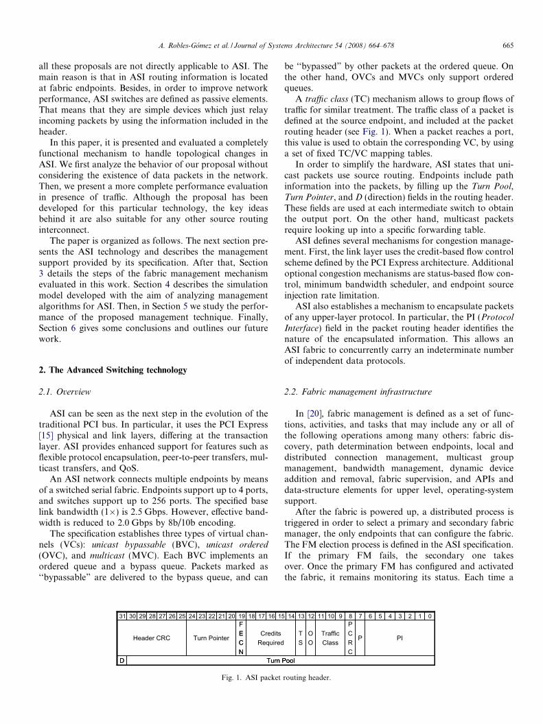
A traffic class (TC) mechanism allows to group flows oftraffic for similar treatment. The traffic class of a packet isdefined at the source endpoint, and included at the packetrouting header (see Fig. 1). When a packet reaches a port,this value is used to obtain the corresponding VC, by usinga set of fixed TC/VC mapping tables.
In order to simplify the hardware, ASI states that uni-cast packets use source routing. Endpoints include pathinformation into the packets, by filling up the Turn Pool,Turn Pointer, and D (direction) fields in the routing header.These fields are used at each intermediate switch to obtainthe output port. On the other hand, multicast packetsrequire looking up into a specific forwarding table.
ASI defines several mechanisms for congestion manage-ment. First, the link layer uses the credit-based flow controlscheme defined by the PCI Express architecture. Additionaloptional congestion mechanisms are status-based flow con-trol, minimum bandwidth scheduler, and endpoint sourceinjection rate limitation.
ASI also establishes a mechanism to encapsulate packetsof any upper-layer protocol. In particular, the PI (Protocol
Interface) field in the packet routing header identifies thenature of the encapsulated information. This allows anASI fabric to concurrently carry an indeterminate numberof independent data protocols.
2.2. Fabric management infrastructure
In [20], fabric management is defined as a set of func-tions, activities, and tasks that may include any or all ofthe following operations among many others: fabric dis-covery, path determination between endpoints, local anddistributed connection management, multicast groupmanagement, bandwidth management, dynamic deviceaddition and removal, fabric supervision, and APIs anddata-structure elements for upper level, operating-systemsupport.
After the fabric is powered up, a distributed process istriggered in order to select a primary and secondary fabricmanager, the only endpoints that can configure the fabric.The FM election process is defined in the ASI specification.If the primary FM fails, the secondary one takesover. Once the primary FM has configured and activatedthe fabric, it remains monitoring its status. Each time a
ool
1
PI
6
P
7PCRC
8910 2
ool
TrafficClass
OO
TS
034511121314
routing header.

Packet Starvation Timeout10000h
Link Capabilities10004h
10008h Link Status
ReservedDLLP Transmit Packet Counter [31:00]
DLLP Transmit Packet Counter [59:32], Control and Status
1000Ch
10010h
10014h
Link Control
...Packet Starvation Timeout10200h
Link Capabilities10204h
10208h Link Status
ReservedDLLP Transmit Packet Counter [31:00]
DLLP Transmit Packet Counter [59:32], Control and Status
1020Ch
10210h
10214h
Link Control
...
AS Capability ID Header100h
Device Capabilities Register104h
108h Device Control and Status
Route Header Revision and Port Count
Device Serial Number [31:00]
Device Serial Number [63:32]Port0 Configuration Record Pointer (10000h)
Port1 Configuration Record Pointer (10200h)
10Ch
110h
114h
118h
11Ch
AP (0 )
...
AP (0)
Next Capability Offset CapVersion AS Capability ID
Reserved BW
BR Type L
BM M PSSupport
OU MP SSupport
BU MP SSupport
Reserved M MPSActive
OU MP SActive
BU MP SActive
Port Number # of PortsRevCap
RevAct Rsvd # Turn
Bits
Reserved V Max LinkSpeed
Max LinkWidth
LS Reserved RsvdDL
RLPLS Negotiated
Link Width NegotiatedLink Speed
TE
LTR
O Size Counter Register [59:32]
31 0
Fig. 2. Structure of the baseline device capability.
666 A. Robles-Gomez et al. / Journal of Systems Architecture 54 (2008) 664–678
topological change is detected, a management process isexecuted in order to update the set of fabric paths. Adetailed description of this process is provided in the nextsection.
To perform its functions, the FM accesses the configura-tion space in each fabric device. It contains up to 16 blocksof 4 Gbytes of storage, called apertures. This storage areaincludes a set of fields to specify device characteristics aswell as fields used to control the device. This informationis presented in the form of structures called capabilities.
As an example, the baseline capability includes devicecontrol and status information. Fig. 2 shows part of thecontents of this capability. Each register is marked withthe corresponding offset inside the aperture 0. The firstsix 32-bit blocks in this capability contain general informa-tion for the device, such as its type (endpoint or switch) andserial number, the number of ports supported, and themaximum packet size. Next, there are up to 256 32-bitblocks that point to the information about each particularport in the device. This information includes link speed andwidth, and current port state.
A ‘‘node configuration and control” protocol (PI-4)allows the FM to access to the configuration space in aremote device. In particular, it obtains information fromany capability by using PI-4 read request packets. Thedevice returns a PI-4 read completion with data packet foreach read request packet, containing the informationrequested (up to eight 32-bit blocks). The path used by
the response is the same as the one used by the request.If the read operation was not successful, a PI-4 read com-pletion with error packet is returned. Apart from read pack-ets, the PI-4 protocol defines write packets that allow theFM to modify any capability. In this case, the specificationdoes not define a response packet.
Another management protocol considered in the ASIspecification is the event-reporting mechanism (PI-5). Aswe will see in the next section, it may be used to detecttopological changes.
3. The fabric management mechanism
This section depicts the behavior of a complete manage-ment mechanism for assimilating a topological change inASI. The basic idea of our proposal is explained in [18].For the sake of simplicity, we assume that the managementfunctions are centralized in the primary FM. In [20], alter-native organizations are discussed. A decentralized mode ismore complex to design, because of the fact that severalmanagers – in different locations and manipulating differ-ent data structures – must be coordinated.
We also assume that the topological and routing infor-mation corresponding to the previous configuration isnot considered by the current assimilation process. Theimplementation of a management technique which reusesprevious information is relatively complex. The reason isthat it must discriminate between reusable and unusable
A. Robles-Gomez et al. / Journal of Systems Architecture 54 (2008) 664–678 667
information, and then, decide the data which must beobtained from the network.
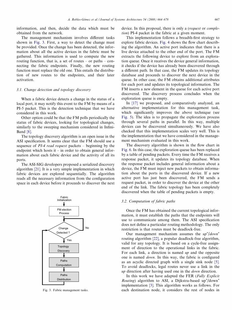
The management mechanism involves different tasksshown in Fig. 3. First, a way to detect the change mustbe provided. Once the change has been detected, the infor-mation about all the active devices in the fabric must begathered. This information is used to compute the newrouting function, that is, a set of routes – or paths – con-necting the fabric endpoints. Finally, the new routingfunction must replace the old one. This entails the distribu-tion of new routes to the endpoints, and their lateractivation.
3.1. Change detection and topology discovery
When a fabric device detects a change in the status of alocal port, it may notify this event to the FM by means of aPI-5 packet. This is the detection technique that we haveconsidered in this work.
Other option could be that the FM polls periodically thestatus of fabric devices, looking for topological changes,similarly to the sweeping mechanism considered in Infini-Band [8].
The topology discovery algorithm is an open issue in theASI specification. It seems clear that the FM should use asequence of PI-4 read request packets – beginning by theendpoint which hosts it – in order to obtain general infor-mation about each fabric device and the activity of all itsports.
The ASI-SIG developers proposed a serialized discoveryalgorithm [21]. It is a very simple implementation in whichfabric devices are explored sequentially. The algorithmreads all the necessary information from the configurationspace in each device before it proceeds to discover the next
Fabric Initialization
FM electionProcess
Topology Discovery
Paths Computation
Paths Distribution
ChangeDetected ?
No
Yes
Topology Discovery
Paths Computation
Paths Distribution
Fig. 3. Fabric management tasks.
device. In this proposal, there is only a (request or comple-
tion) PI-4 packet in the fabric at a given moment.This implementation follows a breadth-first strategy to
explore fabric devices. Fig. 4 shows the flow chart describ-ing the algorithm. An active port indicates that there is alive device attached to the other end of the port. The FMextracts the following device to explore from an explora-tion queue. Once it receives the device general information,it checks if the device has already been discovered througha different path. In that case, the FM updates its topologydatabase and proceeds to discover the next device in thequeue. In other case, the FM obtains additional attributesfor each port and updates its topological information. TheFM inserts a new element in the queue for each active portdiscovered. The discovery process concludes when theexploration queue is empty.
In [17] we proposed, and comparatively analyzed, analternative implementation for this management task,which significantly improves the above technique (seeFig. 5). The idea is to propagate the exploration processthrough several paths in parallel. In this way, multipledevices can be discovered simultaneously. We have alsochecked that this implementation scales very well. This isthe implementation that we have considered in the manage-ment mechanism evaluated in this work.
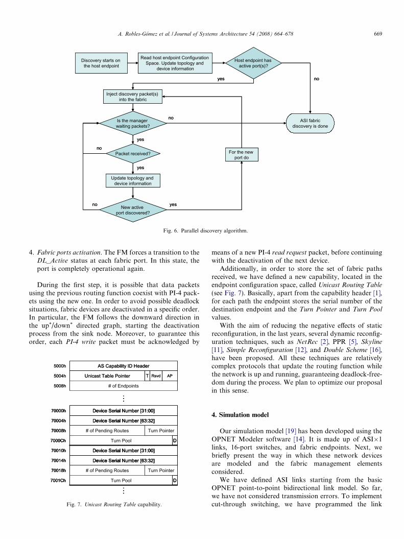
The discovery algorithm is shown in the flow chart inFig. 6. In this case, the exploration queue has been replacedby a table of pending packets. Every time the FM receives aresponse packet, it updates its topology database. Whenthe response packet includes general information about adevice, the FM must inject new packets to obtain informa-tion about the ports in the discovered device. If a newactive port has just been discovered, the FM sends arequest packet, in order to discover the device at the otherend of the link. The fabric topology has been completelydiscovered when the table of pending packets is empty.
3.2. Computation of fabric paths
Once the FM has obtained the current topological infor-mation, it must establish the paths that the endpoints willuse to communicate among them. The ASI specificationdoes not define a particular routing methodology. The onlyrestriction is that routes must be deadlock-free.
Our management mechanism assumes the up*/down*
routing algorithm [22], a popular deadlock-free algorithm,valid for any topology. It is based on a cycle-free assign-ment of direction to the operational links in the fabric.For each link, a direction is named up and the oppositeone is named down. In this way, the fabric is configuredas an acyclic directed graph with a single sink node [5].To avoid deadlocks, legal routes never use a link in theup direction after having used one in the down direction.
In this work we have adapted the FER (Fully Explicit
Routing) algorithm to ASI, a Dijkstra-based up*/down*
implementation [3]. This algorithm works as follows. Foreach destination node, it considers the rest of nodes in

Discovery starts on
the host endpoint
Read host endpoint Configuration Space. Update topology and
device information
Host endpoint has active port(s)?
ASI fabricdiscovery is done
no
Inject device(s) attachedto the active port(s) into
the Device Queue
yes
Is Device Queueempty?
Start discovering the deviceat the head of Device Queue.
Remove it from the Queue
no
Read device’s DSN from Its Configuration Space
Has device already been discovered (i.e. through alternate
paths)?
Update the topology and connectivity information for the device. Stop
discovering the device
Read the additional attributes from device’s
Configuration Space and update topology and
device information
Device has active port(s)?
no
yes
For active port(s) of the device do
no
yes
yes
Discovery starts on the host endpoint
Read host endpoint Configuration Space. Update topology and
device information
Host endpoint has active port(s)?
ASI fabricdiscovery is done
no
Inject device(s) attachedto the active port(s) into
the Device Queue
yes
Is Device Queueempty?
Start discovering the deviceat the head of Device Queue.
Remove it from the Queue
no
Read device’s DSN from Its Configuration Space
Has device already been discovered (i.e. through alternate
paths)?
Update the topology and connectivity information for the device. Stop
discovering the device
Read the additional attributes from device’s
Configuration Space and update topology and
device information
Device has active port(s)?
no
yes
For active port(s) of the device do
no
yes
yes
Fig. 4. Serial discovery algorithm.
Fig. 5. Time required by the serial and parallel discovery algorithms toobtain the fabric topology (average values, the simulation methodology isdetailed in Section 5).
668 A. Robles-Gomez et al. / Journal of Systems Architecture 54 (2008) 664–678
the fabric. This is done by performing a conventional con-trolled flooding, and preventing those hops that involve aforbidden down–up transition.
In [23], an alternative proposal to compute a deadlock-free set of paths is presented. It consists in an adaptation ofthe LASH (Layered Shortest Path) algorithm [10] to theASI technology. To achieve deadlock-freedom, this tech-nique separates the traffic in several layers by using differ-ent sets of virtual channels. Inside each layer, a subset ofsources uses deadlock-free minimal routes to reach a subsetof destinations.
3.3. Distribution of fabric paths
The last phase in the topology change assimilation pro-cess consists in swapping the obsolete routing function bythe updated one. In the literature, this process has beencalled network reconfiguration. It is well-known that,although the new and the old routing functions are bothdeadlock-free, updating fabric paths in an uncontrolledway may lead to deadlock situations, due to the introduc-tion of temporary dependencies among network resources[5].
Earlier reconfiguration mechanisms [22] solved thisproblem by preventing the existence of packets in the net-work during the entire process. We assume this simpleapproach – called static reconfiguration – in this work. Sta-tic reconfiguration may be implemented in ASI in the nextfour sequential steps. These steps are performed by the FMby sending PI-4 packets through the paths computed fromthe new topology.
1. Fabric ports deactivation. The FM forces a transition tothe DL_Protected status at each fabric port. In this sta-tus, the port can only receive and transmit managementpackets (see next section).
2. Tables reset. The FM orders the fabric endpoints todelete its old paths. We assume that this informationis stored in form of routing tables.
3. Tables distribution. The FM fills in the routing tables atthe fabric endpoints with the new set of paths.
Discovery starts on the host endpoint
Read host endpoint Configuration Space. Update topology and
device information
Host endpoint has active port(s)?
ASI fabricdiscovery is done
noyes
Is the manager waiting packets?
yes
Update topology and device information
New active port discovered?
no
For the new port do
no
Inject discovery packet(s) into the fabric
Packet received?no
yes
yes
Fig. 6. Parallel discovery algorithm.
A. Robles-Gomez et al. / Journal of Systems Architecture 54 (2008) 664–678 669
4. Fabric ports activation. The FM forces a transition to theDL_Active status at each fabric port. In this state, theport is completely operational again.
During the first step, it is possible that data packetsusing the previous routing function coexist with PI-4 pack-ets using the new one. In order to avoid possible deadlocksituations, fabric devices are deactivated in a specific order.In particular, the FM follows the downward direction inthe up*/down* directed graph, starting the deactivationprocess from the sink node. Moreover, to guarantee thisorder, each PI-4 write packet must be acknowledged by
...
AS Capability ID Header5000h
Unicast Table Pointer5004h
5008h # of Endpoints
T Rsvd AP
...
Device Serial Number [31:00]70000h
Device Serial Number [63:32]70004h
70008h # of Pending Routes
Turn Pool7000Ch
Turn Pointer
D
Device Serial Number [31:00]70010h
Device Serial Number [63:32]70014h
70018h # of Pending Routes
Turn Pool7001Ch
Turn Pointer
D...
AS Capability ID Header5000h
Unicast Table Pointer5004h
5008h # of Endpoints
T Rsvd AP
...
Device Serial Number [31:00]70000h
Device Serial Number [63:32]70004h
70008h # of Pending Routes
Turn Pool7000Ch
Turn Pointer
D
Device Serial Number [31:00]70000h
Device Serial Number [63:32]70004h
70008h # of Pending Routes
Turn Pool7000Ch
Turn Pointer
D
Device Serial Number [31:00]70010h
Device Serial Number [63:32]70014h
70018h # of Pending Routes
Turn Pool7001Ch
Turn Pointer
D
Device Serial Number [31:00]70010h
Device Serial Number [63:32]70014h
70018h # of Pending Routes
Turn Pool7001Ch
Turn Pointer
D
Fig. 7. Unicast Routing Table capability.
means of a new PI-4 read request packet, before continuingwith the deactivation of the next device.
Additionally, in order to store the set of fabric pathsreceived, we have defined a new capability, located in theendpoint configuration space, called Unicast Routing Table
(see Fig. 7). Basically, apart from the capability header [1],for each path the endpoint stores the serial number of thedestination endpoint and the Turn Pointer and Turn Pool
values.With the aim of reducing the negative effects of static
reconfiguration, in the last years, several dynamic reconfig-uration techniques, such as NetRec [2], PPR [5], Skyline
[11], Simple Reconfiguration [12], and Double Scheme [16],have been proposed. All these techniques are relativelycomplex protocols that update the routing function whilethe network is up and running, guaranteeing deadlock-free-dom during the process. We plan to optimize our proposalin this sense.
4. Simulation model
Our simulation model [19] has been developed using theOPNET Modeler software [14]. It is made up of ASI�1links, 16-port switches, and fabric endpoints. Next, webriefly present the way in which these network devicesare modeled and the fabric management elementsconsidered.
We have defined ASI links starting from the basicOPNET point-to-point bidirectional link model. So far,we have not considered transmission errors. To implementcut-through switching, we have programmed the link

670 A. Robles-Gomez et al. / Journal of Systems Architecture 54 (2008) 664–678
model in such a way that the receiver port can process apacket once the header has been received.
We have also modeled a multiplexed virtual cut-throughswitch [7]. Fig. 8 shows the modules implementing sixswitch ports – numbered from 4 to 9 – the switch arbitra-tion unit, and the crossbar.
Each input channel contains a point-to-point receiver(rcv module in Fig. 8) connected to the link. A selector(ingress_sched module) delivers flow control packets(DLLP, data link layer packet) to the flow control unit.The rest of packets (TLP, transaction layer packet) are sentto the ingress_CSQs module. This module performs theTC/VC mapping, and stores each incoming packet at the
Fig. 8. A detail of the O
tail of the input buffer associated with the correspondingvirtual channel. The number of virtual channels of eachtype and the size of the associated input and output buffersare defined as switch attributes.
Each unicast packet is routed as soon as it reaches theheader of an input buffer. Then, the arbitration unit (arbi-tration_unit module in Fig. 8) receives a request and config-ures the crossbar, taking into account the space available atthe requested output buffer (egress_CSQs) and the status ofthe internal channels.
The flow control unit (DLLP queue module in Fig. 8)models the credit-based flow control defined by the PCIExpress architecture. In particular, it processes incoming
PNET switch model.

Table 1Regular topologies used in the evaluation
Topology Switches Endpoints Total devices
3 � 3 mesh, 3 � 3 torus 9 8 17
A. Robles-Gomez et al. / Journal of Systems Architecture 54 (2008) 664–678 671
DLLPs and activates/deactivates the transmission of TLPsthrough the output channels. It must also inject periodi-cally new DLLPs, in order to update the credit informationat the neighbor port.
Apart from these tasks, the DLLP queue module modelsthe ASI port state machine. Fig. 9 shows the set of possiblestates for a port, as defined in the ASI specification. Oncethe device is powered-on, a port initialization phase starts.Each port tries to synchronize with a potential neighbordevice. To do that, the port transits from DL_Inactive toDL_Init, and sends DLLPs through the link. If the portdoes not receive a response, it returns to the DL_Inactive
state. After some time, it will try to synchronize again.If the port receives a response from the neighbor, they
must negotiate the number of virtual channels which theyare going to use in the communication. When the negotia-tion process finishes, the port transits to the DL_Protected
state. In this state, the transmission of all types of manage-ment packets is allowed.
The FM can order the port to transit to the DL_Active
state by means of a PI-4 packet. In this state, the port iscompletely operational, allowing the transmission of allpacket types. In the same way, the FM can order a transi-tion from DL_Active to DL_Protected. Finally, the portwill return to DL_Inactive if the link or the neighbor deviceis taken down, and DLLPs are not received during a periodof time.
To conclude the description of the switch model, theoutput channel arbitration unit (egress_sched module inFig. 8) receives requests from the port flow control unitand output buffers, and decides the packet that will befinally delivered to the physical link, through the transmit-ter module (xmt). Before sending a TLP, this module mustconsider the credit available at the corresponding neighborinput buffer, which is periodically notified by the flow con-trol unit.
The endpoint model (not shown here) incorporates acommunication port, including exactly the same modulesas a switch port. There is also an application module whichgenerates and consumes upper-level packets. Parametersfor traffic generation, such as packet size and injection rate,are defined as simulation attributes.
Finally, the model includes the aspects of the specifica-tion that provide support for fabric management, that is,the management entities, the device configuration space,and the set of management packets that allow the FM toaccess it.
The model includes a FM module in the endpoint modeland a device_manager module in the endpoint and switchmodels. The FM module models the behavior of a central-
DL_InitDL_Inactive DL_ActiveDL_Protected
Reset
DL_InitDL_Inactive DL_ActiveDL_Protected
Reset
Fig. 9. Port state machine.
ized fabric manager. It handles several data structures tostore the fabric topology, the current set of paths betweenendpoints, and other configuration information. On theother hand, the device_manager module receives read orwrite requests from the FM, accesses to the capabilitiesin the device configuration space, and, if necessary, gener-ates and injects the corresponding responses.
In order to obtain more realistic results, the model con-siders the time consumed by the FM and the fabric devicesto process incoming packets and to perform manage-ment tasks. We have measured this time by using profil-ing techniques, assuming a software implementation forthe management entities, and using an Intel Pentium IV(3.00 GHz) microprocessor.
5. Performance evaluation
In this section, we analyze the behavior of the topologymanagement mechanism described in this work, by meansof several simulation results. Before showing them, the sim-ulation methodology is described.
5.1. Simulation methodology
We have evaluated several regular fabric topologies,including meshes, tori, and fixed radix fat-trees [9]. Table1 includes the complete list. In meshes and tori, each exter-nal switch has an endpoint attached. We have used one andfour VCs per fabric port. The size of the input and outputbuffers associated to each VC is 8 Kbytes.
For the analysis in presence of application traffic, datapacket length has been fixed to 512 bytes. The traffic loadapplied depends on the fabric topology and the amountof VCs available. Generation rate is uniform, and fixedto 25%, 50%, 75%, and 90% of the saturation rate. Trafficsources also use a uniform distribution to obtain the packetdestination among all the active endpoints.
Each simulation begins with a transient period in whichfabric devices are activated and initialized by the FM. Afterthat, we have programmed the occurrence of a topologicalchange, consisting of adding or removing a randomly cho-sen fabric switch. We have chosen a subset of possiblecauses for change, without lack of generality. In orderto obtain more accurate results, for each topology this
4 � 4 mesh, 4 � 4 torus 16 12 286 � 6 mesh, 6 � 6 torus 36 20 568 � 8 mesh, 8 � 8 torus 64 28 929 � 9 torus 81 32 1134-port 2-tree 6 8 144-port 3-tree 20 16 364-port 4-tree 56 32 888-port 2-tree 12 32 44

672 A. Robles-Gomez et al. / Journal of Systems Architecture 54 (2008) 664–678
experiment has been repeated for a 15% of the physicalnodes in the scenario.
5.2. Simulation results
We have carried out three different studies. First, wehave analyzed the performance of the fabric managementmechanism without considering the existence of data pack-ets in the fabric. After that, we have analyzed the influenceof application traffic on the change assimilation time.Finally, we study the way in which the assimilation processcan affect the network performance.
Fig. 11. Time to obtain new routes versus fabric size. Results empiricallyobtained assuming that the FM software is executed in an Intel PentiumIV (3.00 GHz) microprocessor.
Fig. 12. Total amount of management (PI-4) packets required to handle atopological change.
5.2.1. Evaluation in absence of traffic
Fig. 10a shows the time required by the mechanism tocompletely assimilate a change, once it has been detected.Horizontal axis represents the total number of fabricdevices. The values represented are the sum of the timespent by the successive management tasks (discovery, com-putation, and distribution). Obviously, management timeincreases with network size. We can also observe that mostof the time is consumed by the path computation phase.Furthermore, as we can see in Fig. 11, the time requiredby this task has a polynomial behavior.
Fig. 10b details the time required by each step in thepath distribution task shown in Fig. 10a. Note that the‘‘fabric deactivation” and ‘‘tables distribution” steps arethe slowest ones. As we have previously mentioned, the for-mer step requires several acknowledgments from a devicebefore deactivating the ports of the next device. The latterstep involves the access to the path database to obtain theinformation for each PI-4 write packet.
Fig. 12 shows the total number of PI-4 packets requiredby the topology management mechanism, by consideringseparately each phase in the assimilation process. As men-tioned before, the deactivation step is performed in asequential way. Therefore, for each activation packet
Fig. 10. Time required by the proposed mechanism to completely handle a tdistribution time.
(write), three deactivation packets (write, read request,and read completion) were required by the process.
opological change (average results). (a) Total management time (b) Path

A. Robles-Gomez et al. / Journal of Systems Architecture 54 (2008) 664–678 673
We have completed this static evaluation by analyzingthe influence of modifying the performance of the endpointhosting the FM and the rest of fabric devices on the time
(a) Absolute values
Fig. 13. Impact of modifying the FM and device performance on each m
(a) FM =1, Device = 0.2
(c) FM =4, De
Fig. 14. Impact of modifying the FM and device performance on the total assim(b) FM = 1, device = 1; (c) FM = 4, device = 0.2.
required for assimilating a topological change. To do that,we have conducted new simulations by using a factor toincrease or decrease the performance of the FM and the
(a) Percentages
anagement task (9 � 9 torus). (a) Absolute values; (b) Percentages.
(b) FM =1, Device = 1
vice = 0.2
ilation time (regular topologies, average values). (a) FM = 1, device = 0.2;

674 A. Robles-Gomez et al. / Journal of Systems Architecture 54 (2008) 664–678
fabric devices. A factor of one represents the performanceof an Intel Pentium IV (3.00 GHz) microprocessor.
In Fig. 13a, we show the absolute time required by eachphase in the management mechanism, as a function of theperformance factors applied. Results correspond to atopology change consisting in the deactivation of an inter-nal switch in a 9 � 9 torus. Fig. 13b shows the fraction ofthe total management time that each task represents.
Obviously, increasing the performance of the FM affectspositively to all the management tasks. On the other hand,a reduction in the performance of the fabric devices incre-ments the duration of the path distribution phase, while therest of tasks are not affected because they are morecentralized.
Finally, Fig. 14 shows the total management time as afunction of the fabric size and the performance factors con-sidered. Fig. 14b shows the same results as Fig. 10a, butadapting the vertical scale. Fig. 14a represents a slowerdevice, and Fig. 14c represents both a slower device anda faster FM. We can observe that the above tendency isnot dependant on the topology size and type.
Fig. 15. Change assimilation time for different injection rates (one VC
5.2.2. Evaluation in presence of traffic
Figs. 15 and 16 show the impact of modifying the packetinjection rate on the total management time, consideringone and four VCs, respectively. In this case, we have con-sidered a subset of the topologies in Table 1. Results forthe rest of topologies are very similar.
Note that for one VC at each fabric port, managementand data packets must share the same buffers. However,in general, varying the traffic load does not affect thechange assimilation time (see Fig. 15). The reason is thatmanagement packets have the higher priority. Only forvery high traffic loads we can see a light increment on themanagement time. This increment is more noticeable inthe topology discovery phase. The reason is that almostall the steps in the path distribution phase are performedstatically.
However, when the fabric supports more than one VCper port, the management traffic will get a dedicated VCaccording to the ASI specification. This is the reason whythe injection rate does not affect the management trafficat all for the referred cases (see Fig. 16).
, average values). (a) 6 � 6 mesh; (b) 4-port 4-tree; (c) 9 � 9 torus.

(a) 6x6 mesh (b) 4-port 4-tree
(c) 9x9 torus
Fig. 16. Change assimilation time for different injection rates (four VCs, average values). (a) 6 � 6 mesh; (b) 4-port 4-tree; (c) 9 � 9 torus.
A. Robles-Gomez et al. / Journal of Systems Architecture 54 (2008) 664–678 675
Obviously, the presence of application traffic in the net-work does not affect the amount of management packetsrequired to handle a topological change.
5.2.3. Network performance degradationFig. 17 shows the amount of packets which are dis-
carded as a result of the topological change and the corre-sponding assimilation process, as a function of the fabricsize. In these results, we distinguish three different causesof packet discarding. Packets discarded due to ‘‘ProtectedPorts” are those which are dropped during the path distri-bution task, due to the fabric ports are (logically) deacti-vated by the static reconfiguration technique. Packetsdiscarded due to ‘‘Inactive Ports” are those dropped dueto they have reached physically inactive fabric ports, dur-ing the discovery and computation tasks. Obviously, thiscause of discarding only appears due to the change consistsin a device removal. Finally, the ‘‘Inactive Tables” labelrefers to the packets discarded when the routing tables atthe fabric endpoints are inactive during the period of pathupdating.
To conclude this evaluation, Fig. 18 presents someresults to analyze the instantaneous behavior of the man-
agement mechanism. These results have been obtainedby removing an internal switch in a 6 � 6 mesh, at time2.0 s.
The top plot shows the aggregate amount of controlpackets required to detect and completely assimilate thechange. This plot allows us to identify the different tasksin the management process, due to the steps correspondwith the topology discovery and path distribution phases.The second plot shows the latency (from generation) foreach received data packet. The gap corresponds to the sta-tic path distribution phase.
The third and fourth plots show instantaneous networkthroughput, by means of the number of packets per secondsent and received in the whole fabric. Once the fabric portsare deactivated, application packets do not reach their cor-responding destinations. After that, forwarding tables arereset in the sources and therefore no more traffic is injectedinto the network. As the new routing tables are being dis-tributed, traffic injection is progressively recovered, butpackets are immediately discarded due to the network isstill deactivated. Finally, the fabric service is reactivatedand application packets are able to reach their destinationsagain.

(a) Switch removal (b) Switch addition
Fig. 17. Amount of application packets discarded as a consequence of a topological change (four VCs, traffic load: 50% of saturation rate). (a) Switchremoval; (b) switch addition.
Fig. 18. Impact of a switch removal on application traffic (four VCs, traffic load: 50% of saturation rate, 6 � 6 mesh).
676 A. Robles-Gomez et al. / Journal of Systems Architecture 54 (2008) 664–678
6. Conclusions and future work
In this paper we have challenged the problem of assim-ilating topological changes in source routing interconnec-tion networks. In particular, a first fabric mechanism forthe Advanced Switching Interconnect technology is exten-sively detailed and evaluated. This evaluation has been per-formed by using a simulation model which, unlike classicalsimulation tools, incorporates the fabric management sup-port defined by the Advanced Switching specification.
Results show that the main bottleneck in the changeassimilation process is the time required to compute the
new routing function. We have also checked that the per-formance of the FM and the fabric devices may notablyinfluence on the total time. When considering the presenceof traffic in the network, we have seen that it scarcelyaffects the time required by the mechanism. Besides, a hugeamount of data packets are discarded during the assimila-tion process, due to the utilization of obsolete paths, andmainly due to the deactivation of fabric ports before thenew paths begin to be distributed.
As future work, we plan to optimize the process of com-puting the new set of fabric paths, in order to speed up thecomplete change assimilation process. Additionally, we
A. Robles-Gomez et al. / Journal of Systems Architecture 54 (2008) 664–678 677
plan to develop (or adapt) dynamic reconfiguration tech-niques to source routing environments.
Acknowledgements
This work has been jointly supported by the SpanishMEC and European Comission FEDER funds undergrants Consolider Ingenio-2010 CSD2006-00046 andTIN2006-15516-C04-02; by JCCM under grant PBC05-007-1; by UCLM under grant TC20070061. It has alsobeen supported by a FPI grant under the Spanish MECTIC2003-08154-C06-02.
References
[1] Advanced Switching Interconnect Special Interest Group, AdvancedSwitching Core Architecture Specification (Revision 1.0), 2003,<http://www.picmg.org>.
[2] D. Avresky, Dynamic reconfiguration in computer clusters withirregular topologies in the presence of multiple node and link failures,IEEE Transactions on Computers 54 (2005) 5.
[3] A. Bermudez, R. Casado, F.J. Quiles, J. Duato, Fast routingcomputation on InfiniBand networks, IEEE Transactions on Paralleland Distributed Systems 17 (2006).
[4] A. Bermudez, R. Casado, F.J. Quiles, J. Duato, Handling topologychanges in InfiniBand, IEEE Transactions on Parallel and Distrib-uted Systems 18 (2007).
[5] R. Casado, A. Bermudez, F.J. Quiles, J.L. Sanchez, J. Duato, Aprotocol for deadlock-free dynamic reconfiguration in high-speedlocal area networks, IEEE Transactions on Parallel and DistributedSystems 12 (2001).
[6] Dolphin Interconnect Solutions, <http://www.dolphinics.com/>.[7] J. Duato, S. Yalamanchili, L. Ni, Interconnection Networks: An
Engineering Approach, Morgan Kaufmann Publishers, 2003.[8] InfiniBand Trade Association, InfiniBand Architecture Specification
(Revision 1.2), 2003, <http://www.infinibandta.com>.[9] X. Lin, Y. Chung, T. Huang, A multiple LID routing scheme for fat-
tree-based InfiniBand networks, in: Proceeding Eighteenth Interna-tional Parallel and Distributed Processing Symposium, 2004.
[10] O. Lysne et al., Layered routing in irregular networks, IEEETransactions on Parallel and Distributed Systems, vol. 17, January,2006.
[11] O. Lysne, J. Duato, Fast dynamic reconfiguration in irregularnetworks, in: Proceedings of International Conference on ParallelProcessing, August, 2000.
[12] O. Lysne, J.M. Montanana, T.M. Pinkston, J. Duato, T. Skeie, J.Flich, Simple deadlock-free dynamic network reconfiguration, in:Proceedings of International Conference on High PerformanceComputing, December, 2004.
[13] D. Mayhew, V. Krishnan, PCI Express and Advanced Switching:evolutionary path to building next generation interconnects, in:Proceedings of Eleventh Symposium on High Performance Intercon-nects, 2003.
[14] OPNET Technologies, Inc., 2007, <http://www.opnet.com>.[15] PCI-SIG, PCI Express Base Specification (Revision 1.0.a), 2003,
<http://www.pci-sig.org>.[16] T.M. Pinkston, R. Pang, J. Duato, Deadlock-free dynamic reconfig-
uration schemes for increased network dependability, IEEE Trans-actions on Parallel and Distributed Systems 14 (6) (2003).
[17] A. Robles-Gomez, A. Bermudez, R. Casado, F.J. Quiles, Implement-ing the Advanced Switching Fabric Discovery Process, in: Proceed-ings of Workshop on Communication Architecture for Clusters(IPDPS), 2007.
[18] A. Robles-Gomez, A. Bermudez, R. Casado, F.J. Quiles, A completetopology management mechanism for the Advanced Switching
Interconnect technology, in: Proceedings of IEEE Symposium onComputing and Communications, 2007.
[19] A. Robles-Gomez, E.M. Garcıa, A. Bermudez, R. Casado, F.J.Quiles, A model for the development of AS fabric managementprotocols, in: Proceedings of EuroPar 2006 Conference, 2006.
[20] M. Rooholamini, Advanced Switching: a new take on PCI Express,2004, <http://www.edn.com/contents/images/468416.pdf>.
[21] M. Rooholamini, R. Kaapor, Fabric discovery in ASI, 2005, <http://www.networksystemsdesignline.com/showArticle.jhtml?printableAr-ticle= true&articleId=171202366>.
[22] M.D. Schroeder, A.D. Birrell, M. Burrows, H. Murray, R.M.Needham, T.L. Rodeheffer, E.H. Satterthwate, C.P. Thacker, Aut-onet: a high-speed, self-configuring local area network using point-to-point links, IEEE Journal on Selected Areas in Communications 8 (9)(1991) 5–58.
[23] A.G. Solheim, O. Lysne, T. Skeie, T. Sødring, I.T. Theis, I. Johnson,Routing for the ASI Fabric Manager, IEEE CommunicationsMagazine 44 (7) (2006).
[24] Stargen Inc., <http://www.stargen.com/news/pr_20050607.shtml>.
Antonio Robles-Gomez received the M.S. degreein Computer Science from the University ofCastilla-La Mancha in 2004 and is currentlyworking toward the Ph.D. degree. He is now aResearch Associate in the Computer SystemsDepartment at the Castilla-La Mancha Univer-sity. His research interests include routing,configuration, and fault tolerance in high-perfor-mance networks, and network modelling andsimulation.
Aurelio Bermudez is an Associate Professor inComputer Architecture at the Computing Sys-tems Department of the UCLM. He received hisPh.D. in Computer Science in 2004. His researchinterests include modelling, routing, and fault-tolerance in interconnection networks, andlocalization and collaborative processing algo-rithms for wireless sensor networks. He has co-authored more than 25 publications in theseareas.
Rafael Casado received the B.S. degree in Com-puter Science from the University of Castilla-LaMancha in 1993, the M.S. degree in ComputerScience from the University of Murcia in 1995,and the Ph.D. degree in Computer Science fromthe University of Castilla-La Mancha in 2001. In1998 he joined the Department of ComputerEngineering at the University of Castilla-LaMancha and, currently, he is Associate Professorat this department.
His research interests include routing andreconfiguration algorithms for high-speed networks and multicomputers,and intelligent collaborative processing in wireless sensor networks. He
has participated in more than 30 research projects at national and regionallevel, conducting several of them. Currently, he is leading a regionalproject focusing on the use of WSNs to monitor wildfires. He has co-authored more than 30 publications in these areas. He has served as
678 A. Robles-Gomez et al. / Journal of Systems Architecture 54 (2008) 664–678
member of program committee and re-viewer in several conferences andjournals, including some of the most prestigious in these areas.
Francisco J. Quiles received the degree in physics(electronics and computer science) and the Ph.D.degree from the University of Valencia, Spain, in1986 and 1993, respectively. In 1986, he joined theDepartment of Computer Science at the Univer-sity of Castilla-La Mancha, where he is currentlya full professor of computer architecture andtechnology and vice-director of research at theUniversity of Castilla-La Mancha. He has devel-oped several courses on computer organizationand computer architecture. His research interests
include high-performance networks, parallel algorithms for video com-pression, and video transmission. He has published more than 100 papers
in international journals and conferences on performance evaluation ofparallel computer and communications systems and on video compres-sion. He is a member of the IEEE and the IEEE Computer Society.Tor Skeie is an Associate Professor at SimulaResearch Laboratory and the University of Oslo.He received an M.S. degree in Computer Sciencein 1993 and a Ph.D. degree in Computer Sciencein 1998, both from the University of Oslo. He hasseveral years of experience as a researcher in theinterconnect domain. His work mainly focuses onscalability, effective routing, fault tolerance, andquality of service in switched network topologies.Skeie has also experience as a researcher in theindustrial Ethernet area. The key research topics
here have been the road to deterministic Ethernet end-to-end and how toachieve precise time synchronization across switched Ethernet.
Jose Duato received the M.S. and Ph.D. degreesin electrical engineering from the Technical Uni-versity of Valencia, Spain, in 1981 and 1985,respectively. Currently, He is a professor in theDepartment of Computer Engineering (DISCA)at the same university. He was also an adjunctprofessor in the Department of Computer andInformation Science, The Ohio State University.His current research interests include intercon-nection networks and multiprocessor architec-tures. He has published more than 300 refereed
papers. He proposed a powerful theory of deadlock-free adaptive routingfor wormhole networks. Versions of this theory have been used in the
design of the routing algorithms for the MIT Reliable Router, the CrayT3E supercomputer, the internal router of the Alpha 21364 micropro-cessor, the IBM BlueGene/L supercomputer, and the Cray Black Widowsupercomputer. He is the first author of the book Interconnection Net-works: An Engineering Approach. He served as a member of the editorialboards of IEEE Transactions on Parallel and Distributed Systems andIEEE Transactions on Computers. He has been the general cochair for the2001 International Conference on Parallel Processing, the program com-mittee chair for the 10th International Symposium on High PerformanceComputer Architecture (HPCA-10), and the program cochair for the 2005International Conference on Parallel Processing. Also, he has served ascochair, member of the steering committee, vice-chair, or member of theprogram committee in more than 50 conferences, including the mostprestigious conferences in his area (HPCA, ISCA, IPPS/SPDP, IPDPS,ICPP, ICDCS, Europar, and HiPC). He is a member of the IEEE and theIEEE Computer Society.