lunar development and exploration: a simple, long lasting and functionally adaptable architecture
TRANSCRIPT
ISDC 2005, Washington D.C., May 19-22, 2005
Lunar Development and Exploration: A Simple, Long Lasting and Functionally Adaptable Architecture
Donald C Barker and Shalin Mody and Cagri Kanver
Sasakawa International Center for Space Architecture, Houston, Texas, 77204-4000 For the NSS International Space Development Conference 2005
Abstract The paper presents the development of a space architecture designed to support long-term exploration and the permanent habitation of the surface of the moon. Additionally, through the development of judicious, efficient and adaptable systems, this architecture will directly support future Mars exploration efforts. The concept presented herein establishes a functionally simple and reusable inter-lunar cargo transfer infrastructure. A team of graduate architecture students at the University of Houston’s Sasakawa International Center for Space Architecture (SICSA) have, during a two semester period, been researching and designing the proposed exploration architecture based on the newly ascribed space exploration initiative and the evident need for adaptable, flexible and long term program architectures. This work examines a single methodology built upon a review of current, historical and functional assemblages of vehicles combined with the goal of establishing a long lasting and adaptable infrastructure. Additionally, the design is based on a simple, robust and reusable system of vehicles that optimize and incorporate the use of existing technologies. In preparation for eventual increased mass transfer and planetary exploration, this concept also forwards the need to produce, test and operationally establish a heavy lift launch capability. The design initially incorporates two vehicles, the Lunar Transfer Vehicle (LTV), and the Lunar Surface Transfer Vehicle (LSTV.) The LTV, a long standing concept, is reincarnated herein as a derivative of the Russian ISS Service Module which has been modified to carry up to 20 tons of transferable propellant, carry three robotic arms and provide for the docking of lunar cargo. The LSTV is unique and is designed to be an orbit to surface transfer platform capable of placing 30 ton payloads precisely onto the lunar surface. The overall design consists of five functionally operational phases including cargo launch, cargo transfer to a cyclically orbiting LTV, Earth-Moon transit, lunar orbit rendezvous and cargo transfer to the LSTV, and the final transfer of cargo to the lunar surface. System longevity is obtained by continually reusing the primary LTV and LSTV vehicles. Since the cargo is transient, only the initial launch vehicle and vehicle propellant require replacement or replenishment. This additional propellant can be transferred to the LTV either through dedicated re-supply flights or as part of the cargo vehicles staging system. This project provides for a safe, efficient and commercially friendly lunar development architecture that could ultimately focus humanity towards the permanent inhabitation and regular transit between Earth and our planets only naturally orbiting satellite. Therefore, in keeping with the ascribed design criteria, this project highlights an architecture designed uniquely for the Earth moon system that directly enables the development of long duration lunar development and the testing of future Mars habitats and hardware.
1

ISDC 2005, Washington D.C., May 19-22, 2005
Introduction The next significant step in human space exploration requires the establishment of a
clear, sustainable and adaptable goal. In returning humans to the realm of interplanetary exploration and eventually colonization, there is a need to develop and establish a suitable infrastructure that is economical, adaptable and long lasting. This paper introduces an alternative and straightforward lunar exploration and development architecture based on two reusable space-tailored vehicles. The first vehicle is the Lunar Transfer Vehicle (LTV), a dated and yet elegant concept for cyclically transferring cargo between Earth and lunar orbit. The second vehicle, the Lunar Surface Transfer Vehicle (LSTV), is somewhat unique in that it is designed to function, much like a harbor tug, cyclically traveling between the lunar surface and lunar orbit. The LSTV’s surface transfer ability affords lunar base architects and designers more flexibility by removing the need to incorporate propulsion systems and planetary transit-flight power systems into all surface landed habitats and hardware. The LTV and LSTV, in addition to cargo, were also designed to directly support the transfer of human rated and piloted vehicles, including CEV and Earth return vehicle variations by incorporating direct command and control interfaces to which allows piloted control instead of the nominal autonomous operations paradigm.
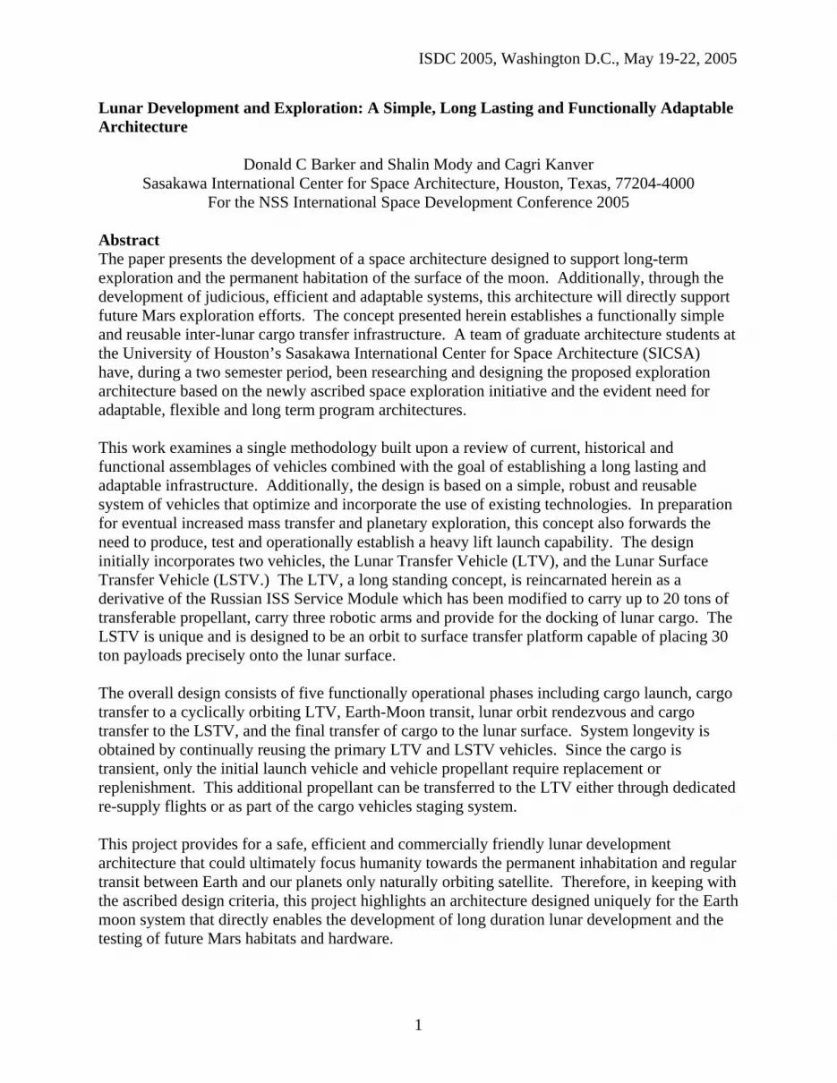
The design of this architecture is guided and encompassed in the concept of total Useful-Cargo-Mass (UCM) landed on the lunar surface. UCM consists of infrastructure, hardware and consumables that directly support human habitation and work. In essence it is the removal of all propulsion systems and related components required to land a vehicle on a planetary surface. The following comparison and example based on the J-series flight Apollo Lunar Module (LM) has been provided in order to demonstrate the UGM approach. It is estimated, given a LM total mass of 15,264 kg (16.8 tonnes), a total loaded propellant mass of 11,010 kg (12.1 tonnes) and a 2,232 kg (2.23 tonnes) dry descent stage mass, that the total UGM for each of these lunar landings was approximately 2,022 kg (2.46 tonnes) or a meager 13.5% of the total mass of the vehicle before initiating the lunar de-orbit (LDO) burn and descending to the surface1,2. This estimate includes the total mass of the LM ascent stage, the 25 kg Apollo Lunar Surface Experiments Package (ALSEP), a 200 kg lunar rover vehicle (LRV), the 17 kg SNAP-27 model RTG power supply and 170 kg of water1. In comparison, the LSTV’s 30 ton maximum estimated UCM capability presented
Figure 1: Apollo Lunar Module – NASA History File3
2
ISDC 2005, Washington D.C., May 19-22, 2005
herein, it would take approximately 8 Apollo LM landings, and therefore 8 Saturn V launches, to emplace the equivalent UCM mass and infrastructure. The architecture being presented herein, would require only four equivalent launches to initially land the same mass, and only two heavy launches per transfer opportunity to provide ongoing maximum mass transfer to the lunar surface. Intermittently, smaller cargos may be transferred using medium lift capable vehicles as long as fuel logistics have been taken into account.
This approach therefore provides a means of rapidly building a sustainable and habitable infrastructure that provides a savings in production, testing, training, operations and launch costs associated with the unusable waste mass of the propulsion section of both historical and newly proposed lunar landing craft. In effect, any long duration lunar exploration and development effort will require the ability to efficiently transfer large amounts of material to the lunar surface and back on a routine basis4.
In this design, the only completely transient mass is that of the common propellant used to transfer the cargo from the Earth to lunar orbit and then from lunar orbit to the surface and back. Both the LTV and LSTV have common and compatible docking interfaces for the transfer of this consumable based on current Russian vehicles and hardware5. As with automobiles, the highest traffic consumable is that of the fuel.
This design effort and mission concept represents the conclusion of a two-semester research project at the University of Houston’s Sasakawa International Center for Space Architecture (SICSA). Beginning with the establishment of the project goals, including the establishment of generic requirements and rationales (see Appendix A), and a fictitious business entity, LunaCor, the project established a means of taking the first steps to permanent interplanetary operations. This goal was accomplished by establishing a lunar development and exploration architecture that was driven by the following three primary objectives: an efficient use and development of both medium and heavy launch assets; designing robust, long-life hardware and operations concepts and abilities, and maximizes landed useful cargo mass. These objectives are important to efficiently establish a growing lunar infrastructure while providing support for the testing and development of directly related Mars applications. We begin by outlining the overall mission architecture and then describing in greater detail the systems and functions of both vehicles. 1.0 Mission Architecture
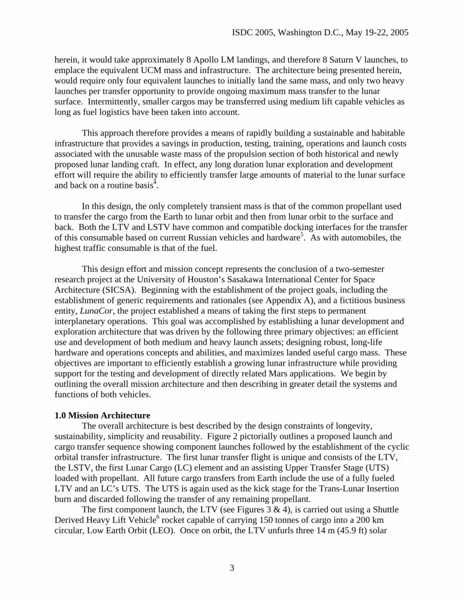
The overall architecture is best described by the design constraints of longevity, sustainability, simplicity and reusability. Figure 2 pictorially outlines a proposed launch and cargo transfer sequence showing component launches followed by the establishment of the cyclic orbital transfer infrastructure. The first lunar transfer flight is unique and consists of the LTV, the LSTV, the first Lunar Cargo (LC) element and an assisting Upper Transfer Stage (UTS) loaded with propellant. All future cargo transfers from Earth include the use of a fully fueled LTV and an LC’s UTS. The UTS is again used as the kick stage for the Trans-Lunar Insertion burn and discarded following the transfer of any remaining propellant.
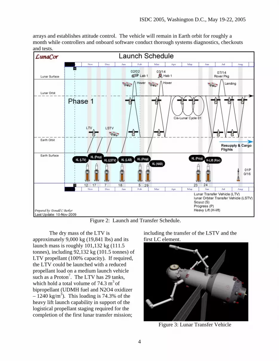
The first component launch, the LTV (see Figures 3 & 4), is carried out using a Shuttle Derived Heavy Lift Vehicle6 rocket capable of carrying 150 tonnes of cargo into a 200 km circular, Low Earth Orbit (LEO). Once on orbit, the LTV unfurls three 14 m (45.9 ft) solar
3
ISDC 2005, Washington D.C., May 19-22, 2005
arrays and establishes attitude control. The vehicle will remain in Earth orbit for roughly a month while controllers and onboard software conduct thorough systems diagnostics, checkouts and tests.
Figure 2: Launch and Transfer Schedule.
The dry mass of the LTV is
approximately 9,000 kg (19,841 lbs) and its launch mass is roughly 101,132 kg (111.5 tonnes), including 92,132 kg (101.5 tonnes) of LTV propellant (100% capacity). If required, the LTV could be launched with a reduced propellant load on a medium launch vehicle such as a Proton7. The LTV has 29 tanks, which hold a total volume of 74.3 m3 of bipropellant (UDMH fuel and N2O4 oxidizer – 1240 kg/m3). This loading is 74.3% of the heavy lift launch capability in support of the logistical propellant staging required for the completion of the first lunar transfer mission;
including the transfer of the LSTV and the first LC element.
Figure 3: Lunar Transfer Vehicle
4
ISDC 2005, Washington D.C., May 19-22, 2005
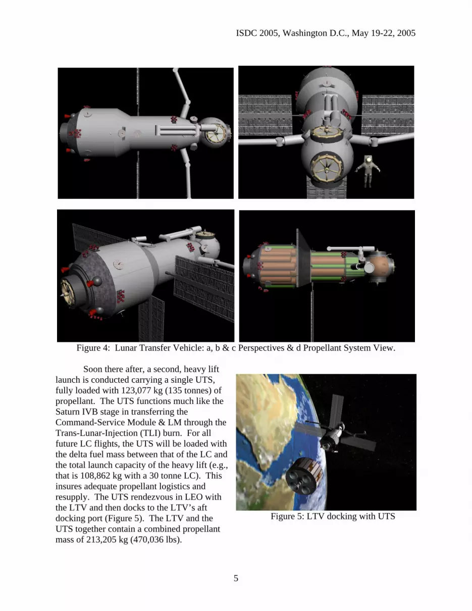
Figure 4: Lunar Transfer Vehicle: a, b & c Perspectives & d Propellant System View.
Soon there after, a second, heavy lift
launch is conducted carrying a single UTS, fully loaded with 123,077 kg (135 tonnes) of propellant. The UTS functions much like the Saturn IVB stage in transferring the Command-Service Module & LM through the Trans-Lunar-Injection (TLI) burn. For all future LC flights, the UTS will be loaded with the delta fuel mass between that of the LC and the total launch capacity of the heavy lift (e.g., that is 108,862 kg with a 30 tonne LC). This insures adequate propellant logistics and resupply. The UTS rendezvous in LEO with the LTV and then docks to the LTV’s aft docking port (Figure 5). The LTV and the UTS together contain a combined propellant mass of 213,205 kg (470,036 lbs).
Figure 5: LTV docking with UTS
5

ISDC 2005, Washington D.C., May 19-22, 2005
Approximately one month following the successful launch, orbit insertion and docking of the UTS to the LTV, another heavy lift launch occurs, lofting the next component into LEO. The LSTV (see Figure 6), which resembles a flying hanger, is folded and collapsed in order to fit the approximate nine-meter diameter launch shroud of the Shuttle Derived Heavy Lift Vehicle. The launch configuration dimensions of the LSTV are 12.5 meters (39.37 feet) long by 8.95 meters (29.46 feet) in diameter. The LSTV total launch weight is approximately 117,055 kg (150 tonnes), where 8000 kg (17,636 lbs) is dry vehicle mass and 109,055 kg is propellant (100% capacity).
Figure 6: Lunar Surface Transfer Vehicle: a,b,c Plan Vies; d Inside Launch Shroud, e & f
Unfolding.
Propellant is stored in 28 1x4 meter (3.28 by 13.12 feet) cylindrical tanks giving a total volume of 87.9 m3. Following successful orbit insertion and launch shroud separation the LSTV unfolds along its long axis, initiates attitude control, expands from its central h-frame structure (Figure 6 d, e & f), and initiates a series of on-orbit functional and systems health checks. Launch constraints require that the LSTV be inserted into a synchronous parking orbit with the previously launched LTV.
The final major preparatory phase prior to the first lunar crossing includes the rendezvous, proximity cargo transfer operations and docking of the LTV/UTS and LSTV vehicles in LEO. This will test the on-board autonomous rendezvous systems and software, and ultimately the docking interface hardware. A standard docking interface (both active and passive), has been adopted for use by a variety of launch and space vehicles: these include Proton, Progress, and HTV. Following a successful docking, interface tests will also be conducted to demonstrate fuel, power and data transfer capabilities. At this point, the vehicles will remain attached in LEO to conduct an approximate month-long certification period prior to initiating lunar transfer.
6
ISDC 2005, Washington D.C., May 19-22, 2005
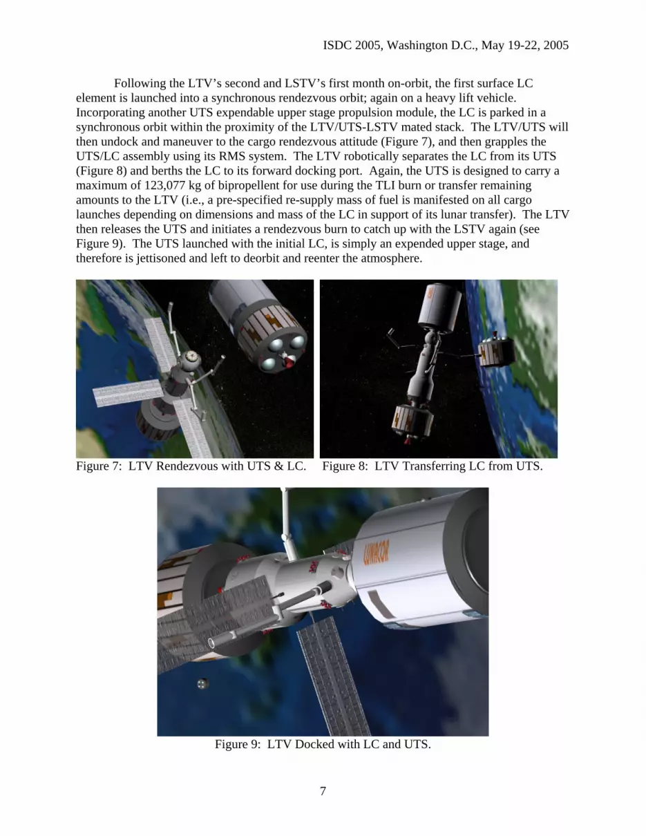
Following the LTV’s second and LSTV’s first month on-orbit, the first surface LC element is launched into a synchronous rendezvous orbit; again on a heavy lift vehicle. Incorporating another UTS expendable upper stage propulsion module, the LC is parked in a synchronous orbit within the proximity of the LTV/UTS-LSTV mated stack. The LTV/UTS will then undock and maneuver to the cargo rendezvous attitude (Figure 7), and then grapples the UTS/LC assembly using its RMS system. The LTV robotically separates the LC from its UTS (Figure 8) and berths the LC to its forward docking port. Again, the UTS is designed to carry a maximum of 123,077 kg of bipropellent for use during the TLI burn or transfer remaining amounts to the LTV (i.e., a pre-specified re-supply mass of fuel is manifested on all cargo launches depending on dimensions and mass of the LC in support of its lunar transfer). The LTV then releases the UTS and initiates a rendezvous burn to catch up with the LSTV again (see Figure 9). The UTS launched with the initial LC, is simply an expended upper stage, and therefore is jettisoned and left to deorbit and reenter the atmosphere.
Figure 7: LTV Rendezvous with UTS & LC. Figure 8: LTV Transferring LC from UTS.
Figure 9: LTV Docked with LC and UTS.
7

ISDC 2005, Washington D.C., May 19-22, 2005
Upon a successful second rendezvous with the LSTV, the LTV maneuvers into the cargo transfer attitude, which is oriented along the LSTV’s long axis and several meters below. This orientation provides for extraction, translation and berthing of the LC into the LSTV’s cargo bay. Once secure, the LSTV’s center axis winch mechanism deploys its 10-meter sheath guided grapple hook (Figures 10, 11 & 12). The hooking mechanism is specially equipped to be grapple and connect to a Universal Transfer Capture Port (UTCP), which is installed on the top of all LCs, thus providing power and two-way data connectivity between the LSTV and the LC.
Figure 10: LTV/LC Rendezvous with LSTV. Figure 11: LTV Transfers LC to LSTV.
Figure 12: LSTV Cargo Grappling. Figure 13: Lunar Transfer Burn.
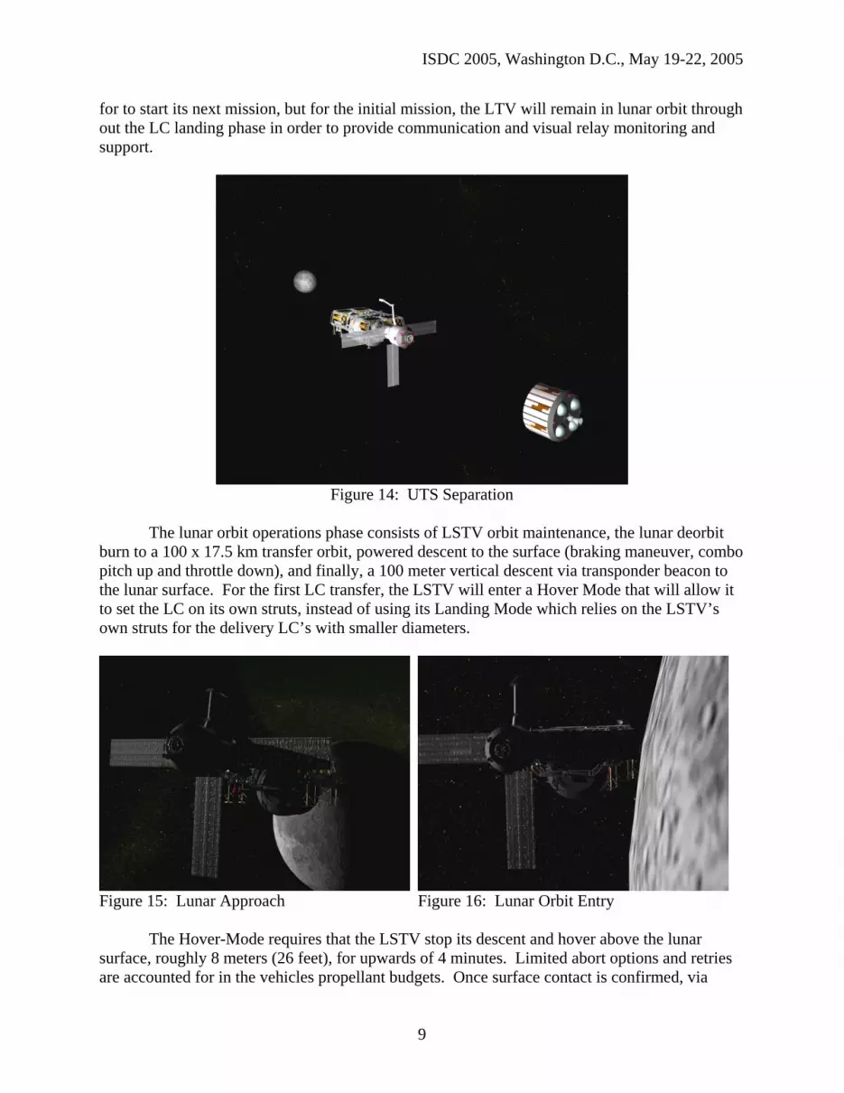
Following a final systems checkout, the LTV/UTS are configured for the trans-lunar burn, and the assembly of four departs Earth for lunar orbit (Figure 13). Shortly following the mid-course correction burn (see Figure 14), the UTS separates from the LTV and is sent off to impact on the lunar surface (similar to the Saturn IVB orbit transfer plan). Roughly 72-hours of transit time is required whereby the LTV maneuvers the stack into a prograde, circular Low Lunar Orbit (LLO) of approximately 100-x-100 km (62.1 mile) altitude (see Figures 15 & 16). Final Fuel transfer operations, from the LSTV to the LTV for this initial mission, are conducted in order to maximize fuel to mass ratios for entry and LC drop off. Following a systems separation checkout, the LSTV with cradled cargo, undocks from the LTV (see Figure 17 & 18) and initiates the lunar orbit operations phase. Nominally, the LTV is now free to return to Earth
8
ISDC 2005, Washington D.C., May 19-22, 2005
for to start its next mission, but for the initial mission, the LTV will remain in lunar orbit through out the LC landing phase in order to provide communication and visual relay monitoring and support.
Figure 14: UTS Separation
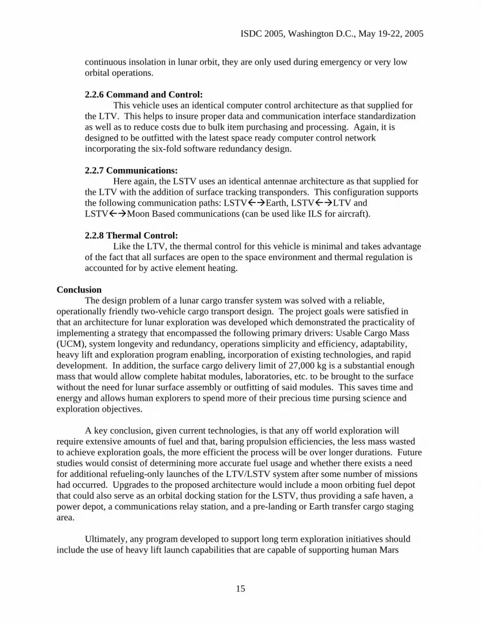
The lunar orbit operations phase consists of LSTV orbit maintenance, the lunar deorbit
burn to a 100 x 17.5 km transfer orbit, powered descent to the surface (braking maneuver, combo pitch up and throttle down), and finally, a 100 meter vertical descent via transponder beacon to the lunar surface. For the first LC transfer, the LSTV will enter a Hover Mode that will allow it to set the LC on its own struts, instead of using its Landing Mode which relies on the LSTV’s own struts for the delivery LC’s with smaller diameters.
Figure 15: Lunar Approach Figure 16: Lunar Orbit Entry
The Hover-Mode requires that the LSTV stop its descent and hover above the lunar surface, roughly 8 meters (26 feet), for upwards of 4 minutes. Limited abort options and retries are accounted for in the vehicles propellant budgets. Once surface contact is confirmed, via
9

ISDC 2005, Washington D.C., May 19-22, 2005
sensors in the LC’s support structure, the LSTV unlatches and initiates its orbit ascent maneuver (Figure 19). This places the LSTV into a circular 100 km lunar parking orbit, awaiting the return of the LTV and a new LC element (Figure 20).
Figure 17: LSTV-LTV Separation Figure 18: LSTV Free-Flying
Figure 19: LC on the Surface Figure 20: LSTV Return to Orbit
The point at which the LSTV reenters lunar orbit marks the establishment of the primary two-vehicle architecture, which is ready to continue the transfer of cargo between the Earth and the Moon in support of rapidly emplacing a large, human ready infrastructure or for directly testing Mars habitat and hardware systems.
The cycle of hardware transfer continues with two heavy lift launches, one UTS and one LC per lunar transfer opportunity or as needed. Two launches are required to logistically insure that an appropriate amount of fuel is loaded and available to each vehicle in order to accomplish a complete lunar surface transfer. Occasionally, depending on overall launch order and LC mass, intermittent propellant only launches may be required to maintain a net positive fuel reserve within the lunar transfer architecture. A fuel requirement analysis8 is provided in Appendix B to this text. The next section provides a more robust explanation of both the LTV and LSTV lunar transport vehicles.
10

ISDC 2005, Washington D.C., May 19-22, 2005
2.0 Vehicle Description 2.1. Lunar Transfer Vehicle (LTV):
The concept of the LTV has been around since the early stages of space flight, and has been depicted in various configurations. In addition, many lunar transition orbital paths such as Earth-Moon direct or Cis/Trans-Lunar Cycling have been proposed9. The vehicle described herein is based on a modified Russian Service Module7 that has been adapted (i.e., gutted) to serve the following primary functions (see Figure 4): first to transfer and store vehicle propellants, and the second to rendezvous, dock and transfer cargo between Earth and lunar orbit.
In order to fulfill such requirements, the LTV would be outfitted with the following systems: rendezvous and docking, propellant storage and transfer; vehicle propulsion (e.g., the Reaction Control Subsystem (RCS)) and nitrogen pressurization subsystems; Guidance, Navigation and Control (GN&C), power generation (i.e., via solar array), thermal regulation (radiators), remote manipulator system (RMS), Command and Control computer system and vehicle communications.
The functional assemblage of major systems is designed so as to be easily accessed and replaced, similar to the concept of ISS orbital replacement units (ORU). Additionally, each system is designed to have three levels of redundancy thus tripling the lifetime of systems operations and establishing functional longevity. Ideally, primary component replacement will be done autonomously and infrequently. Each system is briefly described below, the idea being to capture the highest level of system functionality, beginning with the two systems directly related to the vehicles primary objective for propellant transfer, storage, and cargo acquisition and transfer. 2.1.1 Propulsion and pressurization:
As with all spacecraft this vehicles propulsion section can be functionally subdivided into a pressurization section, a propellant feed section, and the engine assemblies. The propellant section of the LTV contains 29 cylindrical and spherical tanks that store spacecraft fuel and another 31 smaller high-pressure tanks holding compressed nitrogen. Taking as a reference, this architecture assumes the current bipropellent used by Russian space craft, a blend of hydrazine (N2H4) and unsymmetrical dimethylhydrazine (UDMH), commercially known as Aerozine 50. The mix, by weight, is approximately 50% hydrazine, and 50% dimethylhydrazine7. The Isp of UDMH in this mixture is 298 seconds and the oxidizer is nitrogen tetroxide (N2O4). This team assumed the use of an advanced system capable of supporting an Isp of 390 seconds (see Appendix B). The nitrogen system is used to pressurize the fuel lines and propellant tanks providing positive pressure for the active propulsion system and adequate pressure to transfer fuel between all docked vehicles through the common fuel transfer subsystem. 2.1.2 Guidance, Navigation and Control:
This vehicle would be designed to take advantage of a multitude of possible modes of trans-orbital flight, thereby increasing both flexibility and fuel conservation when necessary (e.g., when using longer period cis-lunar cycling during longer periods
11

ISDC 2005, Washington D.C., May 19-22, 2005
when no cargo transfer missions have been designated). An assortment of spacecraft attitude control instruments have are included in the design: rate gyros, horizon sensors, and accelerometers10. Additionally, the LTV can use GPS when within several thousand kilometers of the Earth. 2.1.3 Rendezvous and Docking:
The LTV has one aft and one forward active docking mechanism (i.e, like the current ISS APAS mechanism)5. Additionally, the forward docking ball has an additional two passive docking ports that are routinely used to store various docking adaptors (e.g., an APAS-CBM adaptor) or special cargo pallets. Rendezvous and docking is controlled by a Russian KURS guidance and control system.
The forward and aft docking rings support fuel and power transfer capability, as well as providing command and control connectivity. Therefore, lunar surface modules and hardware act as passive cargo that have no propulsion or power production capability. This design enhances economy and efficiency (i.e., reducing launch mass) for lunar surface module designers by providing the required systems operation support necessary to sustain systems life and operations during the lunar transfer and landing phases. 2.1.4 Power:
The LTV has three 15 meter, gimbaled solar arrays that generate ~5.4 kw of power. The arrays will produce as continuous 4watts/sq.ft. (based on current ISS solar array performance) The three arrays are located in the +/- y, and –z axis. No solar array is located on the +z side of the vehicle do to proximity of vehicles during rendezvous and cargo transfer operations. A subset of batteries is available, but due to near continuous insolation in either the lunar transfer or high planetary orbit, they are only used during low orbital operations. 2.1.5 Command and Control:
This vehicle is designed to be outfitted with the latest space-ready computer control network incorporating a triple redundancy. There will be a total of 13 computers: 3 main command and control (C&C) and 10 shared by the subsystems. Each subsystems software shares hard drive space with two other subsystems; the primary code of each system runs on one computer while its backup runs on a second computer. Only one system’s software runs in the primary or backup slot on each computer at a time. This computer architecture makes software the most redundant spacecraft component (i.e., six fold redundancy), which is especially important given the harsh radiation environment being traversed. The LTV’s primary command computer acts at the bus controller for all other vehicles once docked and data interfaces have been established. The only exception to this is the case when the cargo being transferred is human rated and actively being piloted; then that vehicle has system command authority. 2.1.6 Communications:
The LTV has three S-band or deep space equivalent antennae, which can be used to support simultaneous LTV systems and cargo command, control and monitoring. Two
12

ISDC 2005, Washington D.C., May 19-22, 2005
KU band antennas provide video data downlink capabilities in support of rendezvous, docking and cargo transfer operations. 2.1.7 Thermal Control:
LTV thermal control is the similar to the passive radiative components of the Service Module, given that it does not have to support a pressurized, human tended environment. Thermal control for this vehicle is minimal in that this scheme takes advantage of the fact that most all surfaces are open to the space environment. Therefore, thermal regulation is accounted for by active element and structure heating rather that active heat removal. The system also has localized redundancy to support failed units and assemblies in the event of off-nominal situations. 2.1.8 Robotics:
Three, 3 degree of freedom, 10-meter arms are available for docking, and cargo grappling/maneuvering purposes. One of the three arms has the ability to walk between Power/Data Grapple Fixtures (PDGF), similar to the SSRMS on ISS. This ability enables additional reach and payload placement and manipulation capability.
2.2 Lunar Orbit Transfer Vehicle (LSTV): This vehicle, comparable to proposals by others completes the primary goal of
long duration hardware conservation by providing a reusable transport for a variety of cargos up to 30 Tons (27,215 kg), between lunar orbit and the lunar surface. This capability directly enhances the ability to initiate and rapidly expand human surface development and operations as well as the transport of various interplanetary test modules, components and hardware. The LSTV is launched fully fueled and in a collapsed configuration. Upon reaching its intended 200 km LEO orbit and shedding its launch shroud (see Figure 6), the LSTV unfolds and activates its attitude control system. In addition, the launch is properly sequenced to support a LEO rendezvous with the LTV. Once transported to lunar orbit, it initiates it operational phase, living out its time transporting cargo between the surface and lunar orbit. Cargo of various sizes and shapes may be transported to the surface to be precisely placed via transponder beacon course guidance. One of the unique capabilities of our LSTV concept is its ability to place large cargo elements on the surface either from a hovering posture or by soft landing itself on the surface using its eight reinforced landing struts. The subsystems and architecture of this flying hanger are further expanded and presented below. 2.2.1 Structure:
The vehicle is structured such to be collapsed in order to fit into a 9 meter diameter HLV rocket faring for launch. This presents several unique challenges for rigidizing a deployable arch-like structure. Our solution is to design of the lower joints with a transition pin-rod that crosses adjacent folding members and locks the joint following deployment. Carbon fiber rods fixed to rigid metalwork are the physical elements that make up trapezoidal pyramid truss structure. Carbon fiber rod construction reduces launch weight and allows for a large load-bearing capacity. The cargo bay area of the LSTV is shrouded by an “H-frame” at the center of the structure which supports a 20 tonne-rated winch and cargo cable grappling system. This is where most load paths
13

ISDC 2005, Washington D.C., May 19-22, 2005
end and thus serves as the principle load-bearing structure when encountering accelerations or lunar gravity (1/6 g).
2.2.1.1 Central Structure Cargo Bay/Telescoping Boom: The LSTV Cargo Bay spans a distance of 9 by 10 meters and is capable of
berthing a variety of cargo configurations and shapes, including the large vertical and horizontal cylindrical modules representing oversized standard space station modules or Mars habitat modules.
A sheathed telescoping boom, attached to the H-frame, guide 4 high strength winch cables that are used to grapple and secure the payload for delivery to the surface. Also, additional soft guided pincers and bumpers are provided which secure the payload during lunar descent. A standardized connection to all cargos is provided that enables power and computer control connectivity to the LSTV throughout the capture and landing process.
2.2.2 Propulsion and pressurization:
The LSTV has 8 main landing thrusters and 32 RCS thrusters. Fuel flow rates of approximately 10 kg/s per landing engine can be expected. The main landing thrusters can be gimbaled from the vertical position and outboard several degrees in order to prevent pluming or sandblasting of the lunar cargo during drop off operations. 2.2.3 Guidance, Navigation and Control:
The LSTV is outfitted with software and communications systems capable of maintaining lunar orbit, providing for lunar ascent and descent, and precise trajectory operations using surface transponder beacon systems. These operations will also incorporate the use of laser altimeters and other range finding software and hardware. Finally, the LSTV will be capable of entering a hover mode that supports cargo drop off using the cargo’s support structure surface contact sensors as a means of detecting contact and initiating cargo decoupling and ascent engine firing. 2.2.4 Rendezvous and Docking:
The LSTV has two docking ports, one at each or the vehicles +/- x axis end faces, each acting as the passive side of the docking interface. The rendezvous profile is coordinated and guided by a Russian KURS docking alignment system. The docking ring structure, being a derivative of the Russian APDS docking system5, allows for the docking and capture of the active vehicles (i.e., the LTV) docking mechanism, the connection and transfer of propellant fuels and nitrogen, power connectivity, and command and control data linkages. 2.2.5 Power:
The LSTV has 170 sq. meters of solar cells that are similar to those on the LTV and are capable of generating ~7.2 kw of power. The solar cells are rolled up for launch in cylindrical tubes spanning 10 of the LSTVs large inter truss spaces and are deployed once the vehicle is placed in orbit. A subset of batteries is available, but due to near
14
ISDC 2005, Washington D.C., May 19-22, 2005
continuous insolation in lunar orbit, they are only used during emergency or very low orbital operations. 2.2.6 Command and Control:
This vehicle uses an identical computer control architecture as that supplied for the LTV. This helps to insure proper data and communication interface standardization as well as to reduce costs due to bulk item purchasing and processing. Again, it is designed to be outfitted with the latest space ready computer control network incorporating the six-fold software redundancy design. 2.2.7 Communications:
Here again, the LSTV uses an identical antennae architecture as that supplied for the LTV with the addition of surface tracking transponders. This configuration supports the following communication paths: LSTV Earth, LSTV LTV and LSTV Moon Based communications (can be used like ILS for aircraft). 2.2.8 Thermal Control:
Like the LTV, the thermal control for this vehicle is minimal and takes advantage of the fact that all surfaces are open to the space environment and thermal regulation is accounted for by active element heating.
Conclusion
The design problem of a lunar cargo transfer system was solved with a reliable, operationally friendly two-vehicle cargo transport design. The project goals were satisfied in that an architecture for lunar exploration was developed which demonstrated the practicality of implementing a strategy that encompassed the following primary drivers: Usable Cargo Mass (UCM), system longevity and redundancy, operations simplicity and efficiency, adaptability, heavy lift and exploration program enabling, incorporation of existing technologies, and rapid development. In addition, the surface cargo delivery limit of 27,000 kg is a substantial enough mass that would allow complete habitat modules, laboratories, etc. to be brought to the surface without the need for lunar surface assembly or outfitting of said modules. This saves time and energy and allows human explorers to spend more of their precious time pursing science and exploration objectives.
A key conclusion, given current technologies, is that any off world exploration will require extensive amounts of fuel and that, baring propulsion efficiencies, the less mass wasted to achieve exploration goals, the more efficient the process will be over longer durations. Future studies would consist of determining more accurate fuel usage and whether there exists a need for additional refueling-only launches of the LTV/LSTV system after some number of missions had occurred. Upgrades to the proposed architecture would include a moon orbiting fuel depot that could also serve as an orbital docking station for the LSTV, thus providing a safe haven, a power depot, a communications relay station, and a pre-landing or Earth transfer cargo staging area.
Ultimately, any program developed to support long term exploration initiatives should include the use of heavy lift launch capabilities that are capable of supporting human Mars
15

ISDC 2005, Washington D.C., May 19-22, 2005
missions as well as supporting the testing and transport of long term exploration hardware that, again, directly supports Mars exploration. If implemented correctly, all vehicles and habitats designed for delivering and sustaining humans on Mars should be capable of easily being transformed to support Lunar, planetary orbit and asteroid exploration initiatives.
16
ISDC 2005, Washington D.C., May 19-22, 2005
Appendix A: User requirements (UR), system requirement (SR), design solution (DS) and Functional Design Rationale Assessment.
UR1. Deliver a quality design that ensures simplicity of operation
SR1. System will have no more than 2 main vehicles as part of the transport system.
DS1. One vehicle will act as a space tug for cargo between Earth and Moon orbits – a Lunar Transfer Vehicle (LTV). A second vehicle will transfer cargo between lunar orbit and the lunar surface – a Lunar Surface Transfer Vehicle (LSTV).
Rationale1: This approach simplifies operational needs by having a minimum number of systems to keep track off. Also, it separates Earth orbit to lunar orbit cargo transfer and lunar orbit to Lunar Surface tasks into 1 dedicated vehicle for each task.
UR2. Regular service of the system (after elements are in place) should be in place without a great number of launches.
SR2. Less than 5 launches will be required to put the whole system in place for normal cargo transfer operations.
DS2. Lightweight-high-strength materials (such as carbon-fiber) for vehicle structure and high efficiency propellant will be used to move the mass of the vehicles and the cargo from Earth orbit to the lunar surface. With a two-vehicle system – one launch will be required for each vehicle and another for a fuel module to place the LSTV in Lunar orbit. In the same trip, a full-sized cargo may be traveling on the “set-up” trip as well.
Rationale2: Carbon-fiber composite material can significantly reduce structure mass as well as increase durability and related material properties compared to aluminum. Propellants with high efficiency rating called “specific impulse”, or Isp, can reduce the amount of fuel needed. If less fuel is needed – this could eliminate a number of launches just to “top off” a fuel hungry vehicle before another trip.
UR3. Maximize the use of existing technology in the design
SR3. Vehicle system should have at least 3 major systems utilizing spaceflight proven hardware.
DS3. The propulsion system (propellant and rocket engine), power system (solar arrays and power storage devices), docking systems, and robotic manipulators (for cargo and docking assistance) are all to use previously flown hardware from either the US or Russian space programs.
17

ISDC 2005, Washington D.C., May 19-22, 2005
Rationale3: By using existing systems, technology development and testing is cut out of the total cost of the program. Also, the systems are more readily available for detailed design and system integration efforts.
UR4. Be capable of autonomous orbital maneuvers and rendezvous/docking (after being commanded from ground control).
SR4. Provide ground controllers with data about possible orbit, rendezvous and docking actions in less than 10 minutes from time of request.
DS4. Use computers onboard the vehicle to quickly perform orbit trajectory calculations autonomously and send options to ground control to choose from. Utilize technology available for autonomous docking from Russian space agency.
Rationale4: Creating an orbital guidance/navigation subsystem relieves ground controllers of tasks that can be quickly and autonomously done by computer. Russian docking systems have a proven record and would only incur time and money to adapt it to this new CEV supporting system.
UR5. Simplify the interface design between the vehicle system and other elements to optimize integration.
SR5. No more than 1 type of propellant shall be used for all rocket engines of the entire system. Also, common docking system will be used between vehicle(s) and cargo or extra fuel modules.
DS5. Use proven Unsymmetrical dimethylhydrazine (UDMH) as a common vehicle fuel. The vehicles of the system will have the ability to transfer fuel from/to one another when docked. Also, use either all Russian or US docking systems – both of which are currently available.
Rationale5: UDMH is a rocket fuel that can be stored in harsh environments without it loosing its efficiency or potency. If fuel can be transferred – this will make it possible to leave a little extra fuel for orbit keeping and subsequent cargo transport missions. Using common docking systems allows for flexibility when modules (vehicles, cargo, and/or fuel tanks) need to be connected.
UR6. System should prove to be efficient over its life span.
SR6. System will be reusable and have 50yr life span with human or robotic maintenance performed not less than after every 10yrs in operation.
DS6. Use highly durable carbon-fiber and metals that do not change geometry based on thermal loads. Also, have redundant systems so that maintenance or replace does not have to occur for at least 10yrs years.
18
ISDC 2005, Washington D.C., May 19-22, 2005
Rationale6: The reusability and long life span allows for the system only to require fuel for the transport of cargo. The cargo would not need to bring along its own propulsion system – thereby simplifying the task at the payload customer’s end.
UR7. Maximum payload rating should be substantial.
SR7. Maximum lunar landed cargo is 27,000kg.
DS7. Vehicles will have the propulsion efficiency to push and transport the cargo. The vehicle that takes payload to lunar surface will have a grapple mechanism and materials to take the stresses of lunar gravity and the descent to the surface.
Rationale7: This is nearly twice that of the Apollo lunar module of which on the 5000 kg ascent module was useful on the surface (for crew living, etc.). A full habitat module could be dropped off with 100% utility in habitation because of the splitting of cargo and cargo delivery system vehicles.
19
ISDC 2005, Washington D.C., May 19-22, 2005
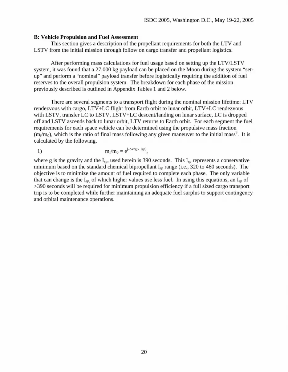
B: Vehicle Propulsion and Fuel Assessment This section gives a description of the propellant requirements for both the LTV and
LSTV from the initial mission through follow on cargo transfer and propellant logistics.
After performing mass calculations for fuel usage based on setting up the LTV/LSTV system, it was found that a 27,000 kg payload can be placed on the Moon during the system “set-up” and perform a “nominal” payload transfer before logistically requiring the addition of fuel reserves to the overall propulsion system. The breakdown for each phase of the mission previously described is outlined in Appendix Tables 1 and 2 below.
There are several segments to a transport flight during the nominal mission lifetime: LTV rendezvous with cargo, LTV+LC flight from Earth orbit to lunar orbit, LTV+LC rendezvous with LSTV, transfer LC to LSTV, LSTV+LC descent/landing on lunar surface, LC is dropped off and LSTV ascends back to lunar orbit, LTV returns to Earth orbit. For each segment the fuel requirements for each space vehicle can be determined using the propulsive mass fraction (mf/m0), which is the ratio of final mass following any given maneuver to the initial mass8. It is calculated by the following, where g is the gravity and the Isp, used herein is 390 seconds. This Isp represents a conservative minimum based on the standard chemical bipropellant Isp range (i.e., 320 to 460 seconds). The objective is to minimize the amount of fuel required to complete each phase. The only variable that can change is the Isp, of which higher values use less fuel. In using this equations, an Isp of >390 seconds will be required for minimum propulsion efficiency if a full sized cargo transport trip is to be completed while further maintaining an adequate fuel surplus to support contingency and orbital maintenance operations.
1) mf/m0 = e[-∆v/g × Isp],
20
ISDC 2005, Washington D.C., May 19-22, 2005
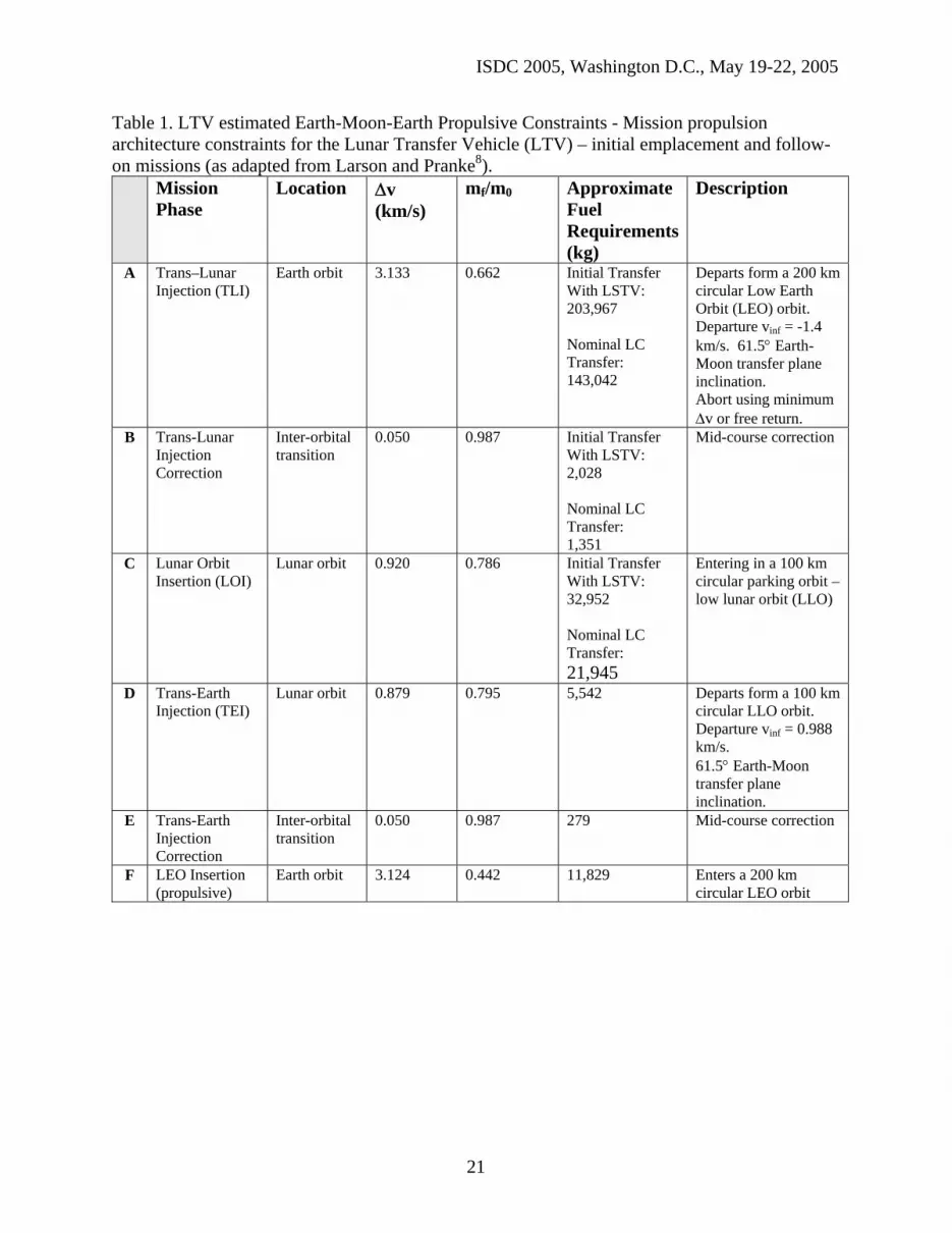
Table 1. LTV estimated Earth-Moon-Earth Propulsive Constraints - Mission propulsion architecture constraints for the Lunar Transfer Vehicle (LTV) – initial emplacement and follow-on missions (as adapted from Larson and Pranke8).
Mission Phase
Location ∆v (km/s)
mf/m0 Approximate Fuel Requirements (kg)
Description
A Trans–Lunar Injection (TLI)
Earth orbit 3.133 0.662 Initial Transfer With LSTV: 203,967 Nominal LC Transfer: 143,042
Departs form a 200 km circular Low Earth Orbit (LEO) orbit. Departure vinf = -1.4 km/s. 61.5° Earth-Moon transfer plane inclination. Abort using minimum ∆v or free return.
B Trans-Lunar Injection Correction
Inter-orbital transition
0.050 0.987 Initial Transfer With LSTV: 2,028 Nominal LC Transfer: 1,351
Mid-course correction
C Lunar Orbit Insertion (LOI)
Lunar orbit 0.920 0.786 Initial Transfer With LSTV: 32,952 Nominal LC Transfer: 21,945
Entering in a 100 km circular parking orbit – low lunar orbit (LLO)
D Trans-Earth Injection (TEI)
Lunar orbit 0.879 0.795 5,542 Departs form a 100 km circular LLO orbit. Departure vinf = 0.988 km/s. 61.5° Earth-Moon transfer plane inclination.
E Trans-Earth Injection Correction
Inter-orbital transition
0.050 0.987 279 Mid-course correction
F LEO Insertion (propulsive)
Earth orbit 3.124 0.442 11,829 Enters a 200 km circular LEO orbit
21

ISDC 2005, Washington D.C., May 19-22, 2005
Table 2. LSTV estimated Lunar Orbit-Surface Transfer Propulsive Constraints - Mission propulsion architecture constraints for the Lunar Surface Transfer Vehicle (LSTV) (as adapted from Larson and Pranke8).
Mission Phase
Location ∆v (km/s)
mf/m0 Approximate Fuel Requirements (kg)
Description
A Lunar Parking Orbit
Lunar orbit marginal A 100 km circular parking / rendezvous orbit
B Lunar Transfer Orbit
Lunar orbit marginal Change orbit to a 100 x 17.5 km elliptical orbit
C Lunar Deorbit (LDO)
Lunar orbit 0.019 0.995 332
D Lunar Descent (with Hover or Landing)
Lunar Orbit-Surface Transition
1.862 0.615 25,691 (+5,000)
Phased Approach: 1) Powered
descent 2) Braking 3) Pitch up /
throttle down 4) Vertical
descent to surface
5) Abort to full Landing
E Lunar Ascent (from surface)
Lunar Surface –Orbit Transition
1.815 0.622 5,280 Enters a 100 x 18.5 km orbit
F Lunar Parking Orbit
Lunar orbit 0.019 0.995 43 Circularization of Lunar parking / rendezvous orbit
22

ISDC 2005, Washington D.C., May 19-22, 2005
References 1 Baker, D., The History of Manned Space Flight, Crown Publishers, Inc, New York, 1981. 2 Lunar Module Fact Sheet, URL: http://nssdc.gsfc.nasa.gov/database/MasterCatalog?sc=1969-
059C 3 NASA History site, URL: http://history.nasa.gov/diagrams/apollo.html 4 Mendell, W. W., ed., Lunar Bases and Space Activities of the 21st Century, Lunar and
Planetary Institute, 1985. 5 Functional Cargo Block Docking and Internal Transfer System, Y. A. Gagarin Cosmonaut
Training Center – Training Manual, Star City, 1998. 6 ATK web site, URL:
http://www.atk.com/AdvancedSpaceSystems/advancespacesystems_rsrmderives.asp 7 NASA Service Module Element Definition, URL:
http://spaceflight.nasa.gov/station/assembly/elements/sm/index.html 8 Larson W.J., Pranke, L.K., ed., Human Spaceflight: Mission Analysis and Design, McGraw
Hill, New York. 9 Uphoff, C., and Crouch, M. A., Lunar Cycler Orbits with Alternating Semi-Monthly Transfer
Windows. Paper No. AAS 91-105, 1991. 10 International Space Station, Guidance, Navigation and Control Training Manual, ISS GNC
TM 21109, NASA, Feb. 1999.
23