lrg-423 2.3 litre industrial engine service manual
TRANSCRIPT
@a LRG-423 Power 2.3 LITRE Products INDUSTRIAL ENGINE
Worldwide TM SERVICE MANUAL
Introduction In general, this manual covers the servicing of the engine and asso- ciated standard equipment. In many cases, engines are supplied with accessories and equipment that are unique to the application. If service information is ever required on such unique accessories or equipment it is suggested that Power Products Division/GRI be con- tacted. The proper information will either be forwarded or the Ser- vice Technician will be advised where it can be obtained.
The information in this manual is grouped in sections according to the type of work being performed. The various sections are indi- cated in the index. In addition, each section is subdivided to include topics such as diagnosis and testing, cleaning and inspection, over- haul, removal and installation procedures, disassembly and assem- bly procedures, and service specifications.
POWER PRODUCTS DIVISION/GRI The Source for Power... 28333 TELEGRAPH ROAD - #300
Worldwide TM SOUTHFIELD, MICHIGAN 48034
The descriptions and specifications contained in this -manual were in effect at the time the book was released for printing. Power Products Division/GRI reserves the right to discontinue models at any time, or change specifications or design, without notice and without incurring obligation.
NOTE: The recommendations and suggestions contained in this publication are made to assist the distributor in improving his distrib- utorship parts and/or service department operations. These recom- mendations and suggestions do not supersede or override the provisions of the Warranty and Policy Manual and in any cases where there may be a conflict, the provisions of the Warranty and Policy Manual shall govern.
01-I Engine Service 01-I
SECTION TITLE PAGE SECTION TITLE PAGE
ENGINE SERVICE . . . . . . . . . . . . . . . . . . . . . . . . . . . . . . . . . . . . . . . . . . . . ..‘...................... 01-I AUXILIARY SYSTEMS . . . . . . . . . . . . . . . . . . . . . . . . . . . . . . . . . . . . . . . . . . . . . . . . . . . . . . . . . . . . . . 03-l
ENGINE SERVICE, 2.3L . . . . . . . . . . . . . . . . . . . . . . . . . . . . . . . . . . . . . . . . . . . . . . . . . . . . . . . . . . . . 02-l
SECTION 01 - Engine Service
SUBJECT DESCRIPTION AND OPERATION
Introduction ............................................................................... 3
Engine Identification Nameplate ............................................. 3
DIAGNOSIS AND TESTING Inspection .................................................................................. 4
Symptom Chart ......................................................................... 4
SERVICE PROCEDURES Positive Crankcase Ventilation (PCV) System
Closed-Type ............................................................................ 6
Engine Oil Leaks ....................................................................... 6
Fluorescent Oil Additive Method .......................................... 6
Pressure Method .................................................................... 6
Testing Procedure .................................................................. 6
Leakage Points ....................................................................... 7
Compression Test ..................................................................... 7
Compression Gauge Check .................................................. 7
Test Results ............................................................................ 7
Compression Pressure Limit Chart ...................................... 7
Compression Readings - Interpreting ................................ 8
Example Readings ................................................................. 8
Cylinder Leakage Detector ....................................................... 8
Oil Leak and Valve Guide Seal Test ........................................ 8
Intake Manifold Vacuum Test .................................................. 8
Vacuum Gauge Readings - Interpretation ........................ .9 Oil Consumption Test .......................................................... 10
Oil Pressure Test .................................................................. 11
Valve Train Analysis -Static (Engine Off) .......................... 11
Rocker Arm/Camshaft Follower Cover Removed ............ .l 1 Rocker/Camshaft Follower Arm Assemblies.. .................. .I 1 Camshaft - 2.3L Engine ..................................................... 11
Valve Springs ....................................................................... 11
Valve Spring Retainer and Valve Spring Keys ................. .I1 Valves and Cylinder Head ................................................... 11
Intake Valve Cleaning (Valves Installed) ............................... 11
Cleaning and Inspection ...................................................... 11
Camshaft Lobe Lift, 2.3L Overhead Camshaft Engine (Camshaft Installed) ................................................ 13
Hydraulic Valve Tappet/Lash Adjuster ................................. 13
Camshaft End Play ................................................................. 13
Timing Belt (2.3L) .................................................................... 14
Camshaft Timing and Cylinder Identification (CID) Timing Check ....................................................................... 14
Crankshaft End Play ............................................................... 15
Connecting Rod Side Clearance ........................................... 15
Cylinder Block ......................................................................... 15
Cleaning and Inspection ...................................................... 15
Cylinder Block Distortion .................................................... 15
Cylinder Head Deck Flatness .............................................. 15 Main Bearing Bore Alignment ............................................. 15
Cylinder Walls, Refinishing .................................................... 16
Cleaning ................................................................................ 16
SUBJECT PAGE SERVICE PROCEDURES (Cont’d.)
Inspection ............................................................................. 16 Cylinder Bore ....................................................................... 16 Cylinder Bore Taper ............................................................ 16 Cylinder Out-of-Round ........................................................ 17 Cylinder Bore Diameter ....................................................... 17 Cylinder Wall Honing .......................................................... 17
Engine Block Plugs ................................................................ 18 Removal and Installation .................................................... 18 Expansion-Type ................................................................... 18 Cup-Type .............................................................................. 18
Crankshaft Main and Connecting Rod Bearings.. ............... 19 Cleaning ............................................................................... 19 Inspection ............................................................................. 19 Crankshaft Main or Connecting Rod Bearings -
Fitting Plastigage@ Method ..... ........ ................ ................ 19 Bore Gauge Method ............................................................ 20
Crankshaft .............................................................................. 21
Cleaning ............................................................................... 21 Inspection ............................................................................. 21 Crankshaft Runout .............................................................. 21 Crankshaft End Play ............................................................ 21
Crankshaft Main Journals and Connecting Rod Journals ................................................................................ 21 Journals Refinishing ........................................................... 21
Crankshaft Sprocket .............................................................. 21 Pistons, Piston Pins and Piston Rings ................................ 22
Cleaning ............................................................................... 22
Inspection ............................................................................. 22 Pistons - Fitting ................................................................. 22 Piston Rings - Fitting ........................................................ 22 Piston and Piston Pin Fit .................................................... 23
Connecting Rods ................................................................... 24 Cleaning ............................................................................... 24 Inspection ............................................................................. 24 Piston Pin Clearance ........................................................... 24
Camshaft ................................................................................. 24 Cleaning ............................................................................... 24 Inspection ............................................................................. 24
Camshaft Bearings ................................................................ 24
Camshaft Bearing Journals .................................................. 25 Camshaft Journals Oil Clearance ...................................... 25
Camshaft Runout ................................................................... 25 Cam Lobe Lift (Camshaft Removed) .................................... 25
With Calipers ........................................................................ 25 On a Camshaft Grinder or Lathe ........................................ 25
Camshaft Sprocket ................................................................ 26 Hydraulic Roller Valve Tappets ............................................ 26
Cleaning ............................................................................... 26 Inspection ............................................................................. 26
01-2 Engine Service 01-2
SECTION 01 - Engine Service SUBJECT PAGE SERVICE PROCEDURES (Cont’d.)
Leakdown Testing ............................................................... 26 Oil Pan ..................................................................................... 27
Cleaning ................................................................................ 27 Inspection ............................................................................. 27
Cylinder Heads ....................................................................... 27 Cleaning ................................................................................ 27 Inspection ............................................................................. 27 Spark Plug Thread Service ................................................. 27 Cylinder Head Flatness ....................................................... 28 Valve Seat Runout ............................................................... 28 Valve Stem-to-Valve Guide Clearance ............................... 28 Valves, Select Fitting ........................................................... 29 Valve Guides, Reaming ....................................................... 29 Valve Seats, Refacing .......................................................... 29 Valves, Inspection ............................................................... 30 Valves, Refacing .................................................................. 30 Valve Spring Tension .......................................................... 31 Valve Spring Squareness .................................................... 31
Camshaft Follower (2.3L) ....................................................... 31 Cleaning ................................................................................ 31 Inspection ............................................................................. 31
Intake Manifold ....................................................................... 31 Cleaning ................................................................................ 31 Inspection ............................................................................. 31
Exhaust Manifold .................................................................... 32 Cleaning ................................................................................ 32 Inspection ............................................................................. 32
SPECIFICATIONS ......................................................................... 32
SPECIAL SERVICE TOOLS/EQUIPMENT ................................... 33
01-3 Engine Service 01-3
DESCRIPTION AND OPERATION
Introduction This section covers various engine tests, adjustments, service procedures and cleaning/inspection procedures. Engine assembly and service specifications appear at the end of Section 02.
For engine disassembly, assembly, installation, adjustment procedures and specifications, refer to Section 02.
The 2.3L engine incorporates a closed-type crankcase ventilation system. Other than the crankcase ventilation system there are no exhaust emission controls or engine/emission control systems used with industrial versions of this engine.
To maintain the required performance level, the fuel system, ignition system and engine must be kept in good operating condition and meet recommended adjustment specifications.
Before replacing damaged or worn engine components such as the crankshaft (6303), cylinder head (6049), valve guide (6510), valves, camshaft (6251) or cylinder block (6010), make sure part(s) is not serviceable.
WARNING: TO AVOID THE POSSIBILITY OF PERSONAL INJURY OR DAMAGE, DO NOT OPERATETHE ENGINE UNTILTHE FAN BLADE (8600) HAS FIRST BEEN EXAMINED FOR POSSIBLE CRACKS OR SEPARATION.
CAUTION: Use of abrasive grinding discs to remove gasket material from the engine sealing surfaces during repair procedures can contribute to engine damage and wear. Airborne debris and abrasive grit from the grinding disc may enter the engine through exposed cavities causing premature wear and eventual engine damage.
Ford Motor Company does not recommend using abrasive grinding discs to remove engine gasket material. Use manual gasket scrapers for removing gasket material from the engine sealing surfaces.
Take added care to prevent scratching or gouging aluminum sealing surfaces.
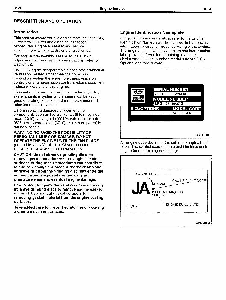
Engine Identification Nameplate For quick engine identification, refer to the Engine Identification Nameplate. The nameplate lists engine information required for proper servicing of the engine. The Engine Identification Nameplate and identification label provide information pertaining to engine displacement, serial number, model number, S.O./ Options, and model code.
PPD0060
\ ENGINE PLANT CODE
-- MADE IN LIMA,OHIO
L - LIMA ENGINE BUILD DATE
1
A24340-A
01-4 Engine Service 01-4
DIAGNOSIS AND TESTING
Inspection 1. Inspect to determine if any of the following
mechanical concerns apply:
l Engine oil leaks.
l Damaged and/or severely worn parts.
l Loose mounting bolts, studs and nuts.
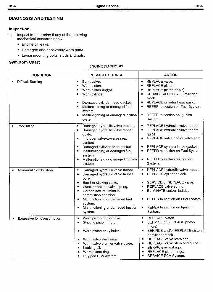
Symptom Chart ENGINE DIAGNOSIS
CONDITION
l Difficult Starting
l Poor Idling
l Abnormal Combustion
l Excessive Oil Consumption
POSSIBLE SOURCE ACTION
l Burnt valve. l REPLACE valve. l Worn piston. l REPLACE piston. l Worn piston ring(s). l REPLACE piston ring(s). l Worn cylinder. l SERVICE or REPLACE cylinder
block. l Damaged cylinder head gasket. l REPLACE cylinder head gasket. l Malfunctioning or damaged fuel l REFER to section on Fuel System.
system. l Malfunctioning or damaged ignition l REFER to section on Ignition
system. System.
l Damaged hydraulic valve tappet. l REPLACE hydraulic valve tappet. l Damaged hydraulic valve tappet l REPLACE hydraulic valve tappet
guide. guide. l Improper valve-to-valve seat l REPLACE valve and/or valve seat.
contact. l Damaged cylinder head gasket. l REPLACE cylinder head gasket. l Malfunctioning or damaged fuel l REFER to section on Fuel System.
system. l Malfunctioning or damaged ignition l REFER to section on Ignition
system. System.
l Damaged hydraulic valve tappet. l REPLACE hydraulic valve tappet. l Damaged hydraulic valve tappet l REPLACE cylinder block.
bore. l Burnt or sticking valve. l SERVICE or REPLACE valve. l Weak or broken valve spring. l REPLACE valve spring. l Carbon accumulation in l ELIMINATE carbon buildup.
combustion chamber. l Malfunctioning or damaged fuel l REFER to section on Fuel System.
system. l Malfunctioning or damaged ignition l REFER to section on Ignition
system. System.
l Worn piston ring groove. l REPLACE piston. l Sticking piston ring(s). l SERVICE or REPLACE piston
ring(s). l Worn piston or cylinder. l SERVICE and/or REPLACE piston
or cylinder block. l Worn valve stem seal. l REPLACE valve stem seal. l Worn valve stem or valve guide. l REPLACE valve stem and guide. l Leaking oil. l SERVICE oil leakage. l Worn piston rings. l REPLACE piston rings. l Plugged PCV system. l SERVICE PCV System.

01-5 Engine Service 01-5
DIAGNOSIS AND TESTING (Continued)
CONDITION
l Engine Noise
POSSIBLE SOURCE ACTION
l Excessive main bearing oil l ADJUST clearance or REPLACEclearance. crankshaft main bearing.
l Seized or heat damaged crankshaft l REPLACE crankshaft main bearing.main bearing.
l Excessive crankshaft end play. l ADJUST end play or REPLACEcrankshaft.
l Excessive connecting rod bearing l ADJUST clearance or REPLACEoil clearance. connecting rod.
l Heat damaged connecting rod l REPLACE connecting rod bearing.bearing.
l Damaged connecting rod bushing. l REPLACE connecting rod bushing.l Worn cylinder. l SERVICE or REPLACE cylinder
block.l Worn piston or piston pin. l REPLACE piston or piston pin.l Damaged piston ring(s). l REPLACE piston ring(s).l Bent connecting rod. l REPLACE connecting rod.l Malfunctioning hydraulic valve l REPLACE hydraulic valve tappet.
tappet.l Excessive hydraulic valve tappet l ADJUST clearance or REPLACE
clearance. hydraulic valve tappet.l Broken valve spring. l REPLACE valve spring.l Excessive valve guide clearance. l SERVICE clearance or REPLACE
valve guide/stem.l Malfunctioning or damaged cooling l REFER to section on Cooling
system. System.l Malfunctioning or damaged fuel l REFER to section on Fuel System.
system.l Leaking exhaust system. l SERVICE exhaust leakage.l Improper drive belt tension. l REFER to section on Access ry
Drivebelts.l Malfunctioning generator bearing. l REFER to section on Chargi :g
System.l Loose timing belt. l ADJUST or REPLACE timing belt.l Damaged timing belt tensioner. l REPLACE timing belt tensioner.l Malfunctioning water pump bearing. l REFER to section on Cooling
System.
l lnsuff icient Power l Malfunctioning hydraulic valve l REPLACE hydraulic valve tappet.tappet.
l Damaged hydraulic valve tappet l REPLACE cylinder block.bore.
l Seized valve stem. l SERVICE or REPLACE valve, valvseat and/or cylinder head.
l Weak or broken valve spring. l REPLACE valve spring.l Damaged cylinder head gasket. l REPLACE cylinder head gasket.l Cracked or distorted cylinder head. l REPLACE cylinder head.l Damaged, worn or sticking piston l SERVICE or REPLACE piston
ring(s). ring(s).l Worn or damaged piston. l REPLACE piston.l Malfunctioning or damaged fuel l REFER to section on Fuel System
system.l Malfunctioning or damaged ignition l REFER to section on Ignition
system. System.
01-6 Engine Service 01-6
SERVICE PROCEDURES
Positive Crankcase Ventilation (PCV) System Closed-Type A malfunctioning closed crankcase ventilation system may be indicated by loping or rough engine idle. Do not attempt to compensate for this idle condition by disconnecting the crankcase ventilation system and making an air bypass or idle speed adjustment. The removal of the crankcase ventilation system from the engine will adversely affect fuel economy and engine crankcase ventilation with resultant shortening of engine life.
Engine Oil Leaks NOTE: Due to their remote location, rear engine oil leaks may be very difficult to pinpoint. This area is also very difficult to clean. Make sure to eliminate all other possibilities before removing the engine to repair a suspected leak in this area.
When diagnosing engine oil leaks, it is important that the source and location of the leak be positively identified prior to service. There are two methods of diagnosing engine oil leaks. The following procedure has been found to be very effective and requires only a minimum of equipment. Prior to using this procedure, it is important to clean the cylinder block (6010), cylinder heads (6049), valve covers (6582), oil pan (6675) and flywheel housing areas with a suitable solvent to remove all traces of oil.
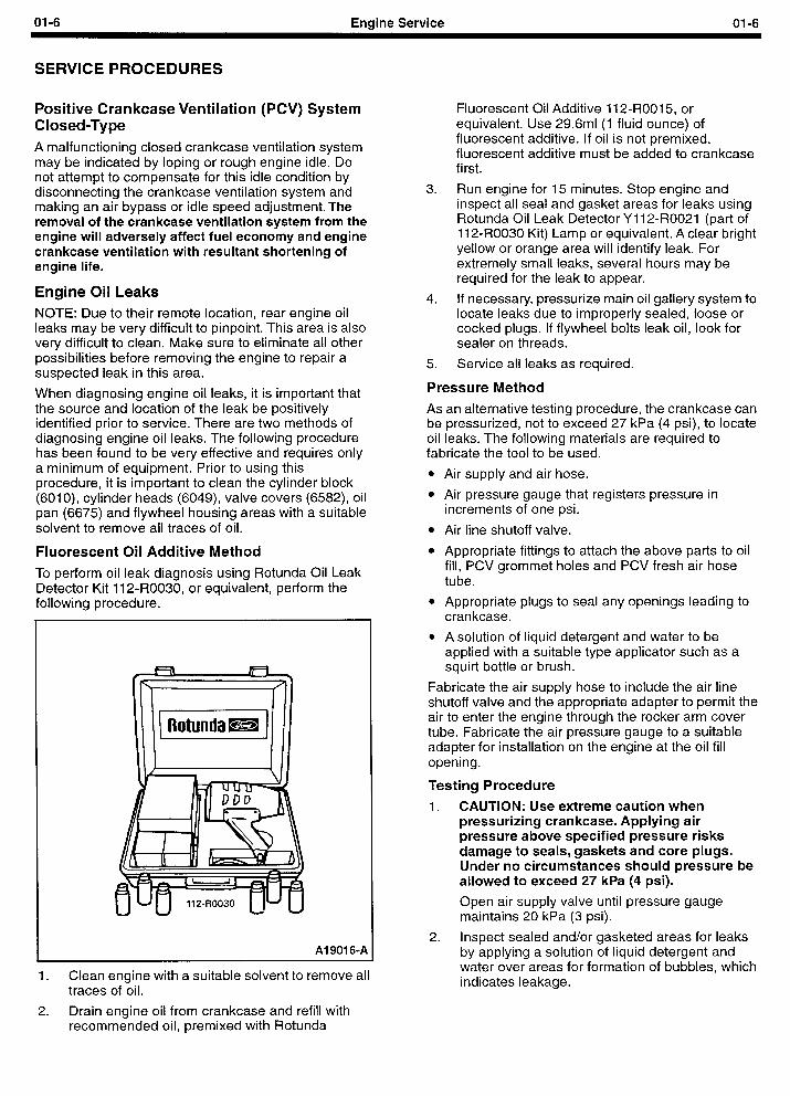
Fluorescent Oil Additive Method
To perform oil leak diagnosis using Rotunda Oil Leak Detector Kit 112.R0030, or equivalent, perform the followina procedure.
1. Clean engine with a suitable solvent to remove all traces of oil.
2. Drain engine oil from crankcase and refill with recommended oil, premixed with Rotunda
Al 9016-A
Fluorescent Oil Additive 112-ROOI 5, or equivalent. Use 29.6ml (1 fluid ounce) of fluorescent additive. If oil is not premixed, fluorescent additive must be added to crankcase first.
3. Run engine for 15 minutes. Stop engine and inspect all seal and gasket areas for leaks using Rotunda Oil Leak Detector Y 112-R0021 (part of 112-R0030 Kit) Lamp or equivalent. A clear bright yellow or orange area will identify leak. For extremely small leaks, several hours may be required for the leak to appear.
4. If necessary, pressurize main oil gallery system to locate leaks due to improperly sealed, loose or cocked plugs. If flywheel bolts leak oil, look for sealer on threads.
5. Service all leaks as required.
Pressure Method
As an alternative testing procedure, the crankcase can be pressurized, not to exceed 27 kPa (4 psi), to locate oil leaks. The following materials are required to fabricate the tool to be used.
l Air supply and air hose.
l Air pressure gauge that registers pressure in increments of one psi.
l Air line shutoff valve.
l Appropriate fittings to attach the above parts to oil fill, PCV grommet holes and PCV fresh air hose tube.
l Appropriate plugs to seal any openings leading to crankcase.
l A solution of liquid detergent and water to be applied with a suitable type applicator such as a squirt bottle or brush.
Fabricate the air supply hose to include the air line shutoff valve and the appropriate adapter to permit the air to enter the engine through the rocker arm cover tube. Fabricate the air pressure gauge to a suitable adapter for installation on the engine at the oil fill opening.
Testing Procedure
1. CAUTION: Use extreme caution when pressurizing crankcase. Applying air pressure above specified pressure risks damage to seals, gaskets and core plugs. Under no circumstances should pressure be allowed to exceed 27 kPa (4 psi).
Open air supply valve until pressure gauge maintains 20 kPa (3 psi).
2. Inspect sealed and/or gasketed areas for leaks by applying a solution of liquid detergent and water over areas for formation of bubbles, which indicates leakage.
01-7 Engine Service 01-7
SERVICE PROCEDURES (Continued)
Leakage Points Examine the following areas for oil leakage.
l Rocker cover sealant or gaskets
l Intake manifold gaskets/end seals
l Cylinder head gaskets
l Oil bypass filter (6714)
l Oil level indicator (dipstick) tube connection
l Oil pressure sensor (9278)
l Cup plugs and/or pipe plugs at end of oil passages
l Oil pan gasket (6710)
l Oil pan front and rear end seals
l Crankshaft front seal (6700)
l Crankshaft rear oil seal (6701)
l Oil pump
l Crankshaft rear oil seal (6701)
Air leakage in area around a crankshaft rear oil seal (6701) does not necessarily indicate a rear seal leak. However, if no other cause can be found for oil leakage, it can be assumed that rear seal is the cause of the oil leakage.
l Rear main bearing cap parting line.
l Rear main bearing cap and seals.
l Flywheel mounting bolt holes.
l Rear cup plugs and/or pipe plugs at the end of oil passages.
Oil leaks at crimped seams in sheet metal parts and cracks in cast or stamped parts can be detected when pressurizing the crankcase.
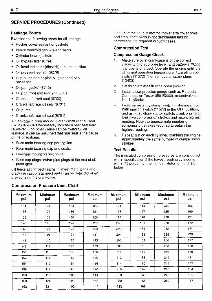
Compression Pressure Limit Chart
Light foaming equally around rocker arm cover bolts and crankshaft seals is not detrimental and no corrections are required in such cases.
Compression Test
Compression Gauge Check 1.
5.
Make sure oil in crankcase is of the correct viscosity and at proper level, and battery (10655) is properly charged. Operate the engine until it is at normal operating temperature. Turn off ignition switch (11572), then remove all spark plugs (12405).
Set throttle plates in wide-open position.
Install a compression gauge such as Rotunda Compression Tester 059-R0009, or equivalent, in No. 1 cylinder.
Install an auxiliary starter switch in starting circuit. With ignition switch (11572) in the OFF position, and using auxiliary starter switch, crank engine at least five compression strokes and record highest reading. Note the approximate number of compression strokes required to obtain the highest reading.
Repeat test on each cylinder, cranking the engine approximately the same number of compression strokes.
Test Results The indicated compression pressures are considered within specification if the lowest reading cylinder is within 75 percent of the highest. Refer to the chart below.
Maximum Minimum Maximum Minimum Maximum Minimum Maximum Minimum psi psi psi psi psi psi psi psi
734 707 764 723 794 745 224 768
136 102 766 724 796 147 226 169
738 704 768 726 798 748 228 171 I
140 105 170 127 200 750 230 772
742 707 772 129 202 157 232 774
744 708 174 131 204 753 234 775
746 170 776 132 206 754 236 777
748 771 178 133 208 156 238 778
750 173 180 135 270 757 240 180
752 774 782 736 212 758 242 787 ,
754 775 184 138 214 160 244 783
156 777 186 140 216 762 246 184
758 718 188 141 218 163 248 186
160 120 190 742 220 165 250 187
762 121 192 144 222 166
01-8 Engine Service 01-8
SERVICE PROCEDURES (Continued)
Compression Readings - Interpreting
It is recommended the Compression Pressure Limit Chart be used when checking cylinder compression so that the lowest reading number is 75 percent of the highest reading.
If one or more cylinders reads low, squirt approximately one tablespoon of SAE 50 weight, or equivalent, engine oil on top of the pistons in the low reading cylinders. Repeat compression pressure check on these cylinders.
1. If compression improves considerably, piston rings are at fault.
2. If compression does not improve, valves are sticking or seating poorly.
3. If two adjacent cylinders indicate low compression pressures and squirting oil on pistons does not increase compression, cause may be a cylinder head gasket leak between cylinders. Engine oil and/or coolant in cylinders could result from this problem.
Example Readings
If, after checking the compression pressures in all cylinders, it was found that the highest reading obtained was 1351 kPa (196 psi) and the lowest pressure reading was 1069 kPa (155 psi), the engine is within specification and the compression is considered satisfactory.
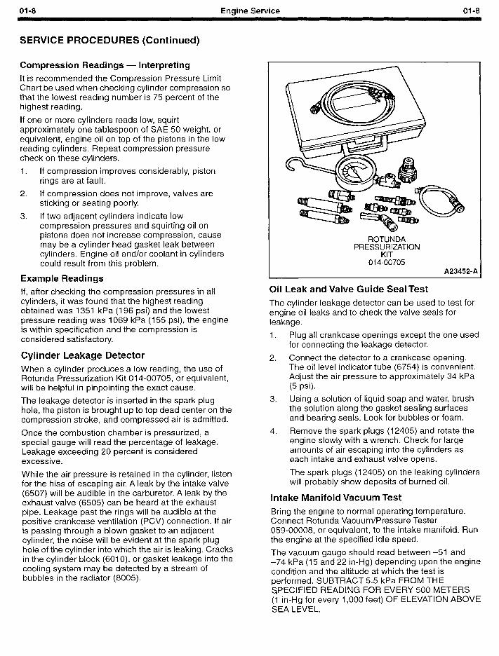
Cylinder Leakage Detector When a cylinder produces a low reading, the use of Rotunda Pressurization Kit 014-00705, or equivalent, will be helpful in pinpointing the exact cause.
The leakage detector is inserted in the spark plug hole, the piston is brought up to top dead center on the compression stroke, and compressed air is admitted.
Once the combustion chamber is pressurized, a special gauge will read the percentage of leakage. Leakage exceeding 20 percent is considered excessive.
While the air pressure is retained in the cylinder, listen for the hiss of escaping air. A leak by the intake valve (6507) will be audible in the carburetor. A leak by the exhaust valve (6505) can be heard at the exhaust pipe. Leakage past the rings will be audible at the positive crankcase ventilation (PCV) connection. If air is passing through a blown gasket to an adjacent cylinder, the noise will be evident at the spark plug hole of the cylinder into which the air is leaking. Cracks in the cylinder block (6010), or gasket leakage into the cooling system may be detected by a stream of bubbles in the radiator (8005).
ROTUNDA PRESSURIZATION
KIT 014-00705
A23452-A
-
Oil Leak and Valve Guide Seal Test
The cylinder leakage detector can be used to test for engine oil leaks and to check the valve seals for leakage.
1. Plug all crankcase openings except the one used for connecting the leakage detector.
2. Connect the detector to a crankcase opening. The oil level indicator tube (6754) is convenient. Adjust the air pressure to approximately 34 kPa (5 psi).
3. Using a solution of liquid soap and water, brush the solution along the gasket sealing surfaces and bearing seals. Look for bubbles or foam.
4. Remove the spark plugs (12405) and rotate the engine slowly with a wrench. Check for large amounts of air escaping into the cylinders as each intake and exhaust valve opens.
The spark plugs (12405) on the leaking cylinders will probably show deposits of burned oil.
Intake Manifold Vacuum Test
Bring the engine to normal operating temperature. Connect Rotunda Vacuum/Pressure Tester 059-00008, or equivalent, to the intake manifold. Run the engine at the specified idle speed.
The vacuum gauge should read between -51 and -74 kPa (15 and 22 in-Hg) depending upon the engine condition and the altitude at which the test is performed. SUBTRACT 5.5 kPa FROM THE SPECIFIED READING FOR EVERY 500 METERS (1 in-Hg for every 1,000 feet) OF ELEVATION ABOVE SEA LEVEL.
01-9 Engine Service 01-9
SERVICE PROCEDURES (Continued)
The reading should be quite steady. It may be necessary to adjust the gauge damper control (where used) if the needle is fluttering rapidly. Adjust damper until needle moves easily without excessive flutter.
Vacuum Gauge Readings - Interpretation
A careful study of the vacuum gauge reading while the engine is idling will help pinpoint trouble areas. Always conduct other appropriate tests before arriving at a final diagnostic decision. Remember that vacuum gauge readings, although helpful, must be interpreted with care.
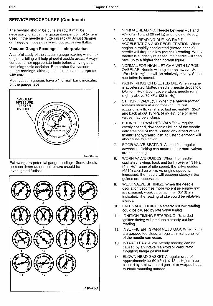
Most vacuum gauges have a “normal” band indicated on the aauae face.
VACUUM/ PRE
TE 059
A23453-A
Following are potential gauge readings. Some should be considered as normal; others should be investigated further.
Al 0428-P
1.
2.
3.
4.
5.
6.
7.
8.
9.
NORMAL READING: Needle between -51 and -74 kPa (15 and 20 in-Hg) and holding steady.
NORMAL READING DURING RAPID ACCELERATION AND DECELERATION: When engine is rapidly accelerated (dotted needle), needle will drop to a low (not to 0) reading. When throttle is suddenly released, the needle will snap back up to a higher than normal figure.
NORMAL FOR HIGH LIFT CAM WITH LARGE OVERLAP: Needle will register as low as -50 kPa (15 in-Hg) but will be relatively steady. Some oscillation is normal.
WORN RINGS OR DILUTED OIL: When engine is accelerated (dotted needle), needle drops to 0 kPa (0 in-Hg). Upon deceleration, needle runs slightly above 74 kPa (22 in-Hg).
STICKING VALVE(S): When the needle (dotted) remains steady at a normal vacuum but occasionally flicks (sharp, fast movement) down and back about 13 kPa (4 in-Hg), one or more valves may be sticking.
BURNED OR WARPED VALVES: A regular, evenly spaced, downscale flicking of the needle indicates one or more burned or warped valves. lnsuff icient hydraulic lash adjuster clearance will also cause this action.
POOR VALVE SEATING: A small but regular downscale flicking can mean one or more valves are not seating.
WORN VALVE GUIDES: When the needle oscillates (swings back and forth) over a 13 kPa (4 in-Hg) range at idle speed, the valve guides (6510) could be worn. As engine speed is increased, the needle will become steady if the guides are responsible.
WEAK VALVE SPRINGS: When the needle oscillation becomes more violent as engine rpm is increased, weak valve springs (6513) are indicated. The reading at idle could be relatively steady.
10. LATE VALVE TIMING: A steady but low reading could be caused by late valve timing.
11. IGNITION TIMING RETARDING: Retarded ignition timing will produce a steady but low reading.
12. INSUFFICIENT SPARK PLUG GAP: When plugs are gapped too close, a regular, small pulsation of the needle can occur.
13. INTAKE LEAK: A low, steady reading can be caused by an intake manifold or carburetor mounting flange gasket leak.
14. BLOWN HEAD GASKET A regular drop of approximately 33-50 kPa (1 O-l 5 in-Hg) can be caused by a blown head gasket or warped head- to-block mounting surface.
01-10 Engine Service 01-10
SERVICE PROCEDURES (Continued)
15. RESTRICTED EXHAUST SYSTEM: When the engine is first started and is idled, the reading may be normal. But, as the engine rpm is increased, back pressure caused by a clogged exhaust pipe, etc., will cause the needle to slowly drop to 0. The needle then may slowly rise. Excessive exhaust clogging will cause the needle to drop to a low point even if the engine is only idled.
When vacuum leaks are indicated, search out and correct the condition. Excess air leaking into the system will upset the fuel mixture and cause conditions such as rough idle, missing, or burned valves. ALWAYS SERVICE VACUUM LEAKS.
Oil Consumption Test
The following diagnostic procedure is intended to be used to determine the source of excessive internal oil consumption.
1. Determine what is considered to be excessive oil consumption. Note hours of engine service and the following observations:
a. How many hours of engine use per 0.95 liter (1 U.S. quart) of oil used?
b. How is the engine being used (e.g., sustained high-speed operation, heavy loads, high ambient temperature, etc.)?
c. What is the expected normal oil consumption?
2. Verify that the engine has no external oil leak as described under Engine Oil Leaks in this section.
3. Verify that the oil level dipstick (6750) and oil level indicator tube (6754) are unmodified and in good condition. Verify that the oil level indicator tube (6754) is properly seated in the block, and the dipstick seats properly in the oil level indicator tube (6754).
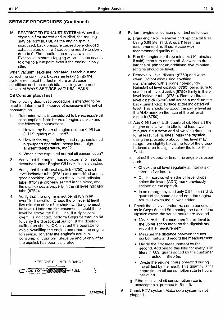
4. Verify that the engine is not being run in an overfilled condition. Check the oil level at least five minutes after a hot shutdown (engine must be level). Under no circumstances should the oil level be above the FULL line. If a significant overfill is indicated, perform Steps 5a through 5d to verify the dipstick calibration. If the dipstick calibration checks OK, instruct the operator to avoid overfilling the engine and return the engine to service. To verify the engine’s actual oil consumption, perform Steps 5e and 5f only after the dipstick has been calibrated.
KEEP THE OIL IN THIS RANGE
Al 7629-E
5. Perform engine oil consumption test as follows:
a. Drain engine oil. Remove and replace oil filter. Using 0.95 liter (1 U.S. quart) less than recommended, refill crankcase with recommended quality of oil.
b. Run the engine for three minutes (10 minutes if cold), then turn engine off. Allow oil to drain into the oil pan for an additional five minutes (engine should be level).
c. Remove oil level dipstick (6750) and wipe clean. Do not wipe using anything contaminated with silicone compounds. Reinstall oil level dipstick (6750) being sure to seat the oil level dipstick (6750) firmly in the oil level indicator tube (6754). Remove the oil level dipstick (6750) and scribe a mark on the back (unmarked) surface at the indicated oil level. This should be about the same level as the ADD mark on the face of the oil level dipstick (6750).
d. Add 0.95 liter (1 U.S. quart) of oil. Restart the engine and allow it to idle for at least two minutes. Shut down and allow oil to drain back for at least five minutes. Mark the dipstick using the procedure above. This level may range from slightly below the top of the cross- hatched area to slightly below the letter F in FULL.
e. Instruct the operator to run the engine as usual and:
l Check the oil level regularly at intervals of three to five hours.
l Call for service when the oil level drops below the lower (ADD) mark previously scribed on the dipstick.
l In an emergency, add only 0.95 liter (1 U.S. quart) of the same oil and note the engine hours at which the oil was added.
f. Check the oil level under the same conditions as in Steps 5c and 5d, reading the back of the dipstick where the scribe marks are located.
l Measure the distance from the oil level to the upper scribe mark on the dipstick and record the measurement.
l Measure the distance between the two scribe marks and record the measurement.
l Divide the first measurement by the second. Add one to this total for every 0.95 liters (1 U.S. quart) added by the customer as instructed in Step 5e.
l Divide the engine hours operated during the oil test by the result. This quantity is the approximate oil consumption rate in hours per quart.
g. If the calculated oil consumption rate is unacceptable, proceed to Step 6.
6. Check PCV system. Make sure system is not plugged.
01-11 Engine Service 01-l 1
SERVICE PROCEDURES (Continued)
7.
IO.
Check for plugged oil drain-back holes in cylinder - heads (6049) and cylinder block (6010).
If condition still exists, perform a cylinder compression test as described in this section, and/or perform a cylinder leak detection test with Rotunda Pressurization Kit 014-00705, or equivalent. This can be helpful in determining the source of oil consumption, as an example, valves, piston rings, etc.
Check valve guides (6510) for excessive clearance. Replace all valve stem seals (6A517) after correct valve guide clearance has been verified.
NOTE: After checking for worn parts, if it is determined parts should be replaced, make sure correct replacement parts are used. Worn or damaged internal engine components can cause excessive oil consumption. Small deposits of oil on tip of spark plugs (12405) can be a clue to internal oil consumption. If internal oil consumption still persists, proceed as follows:
a. Remove intake manifold(s), cylinder heads (6049), oil pan and oil pump.
b. Check piston ring clearance, ring gap and ring orientation as outlined in this section. Service as required.
c. Check for excessive bearing clearance as outlined in this section. Service as required.
11. Perform Step 5 again to verify that the oil consumption concern has been resolved.
Oil Pressure Test
SPECIAL SERVICE TOOL(S) REQUIRED
Description I Tool Number I 1 Engine Oil Pressure Gauge 1 T73L-6600-A I
1.
2.
3.
4.
5.
6.
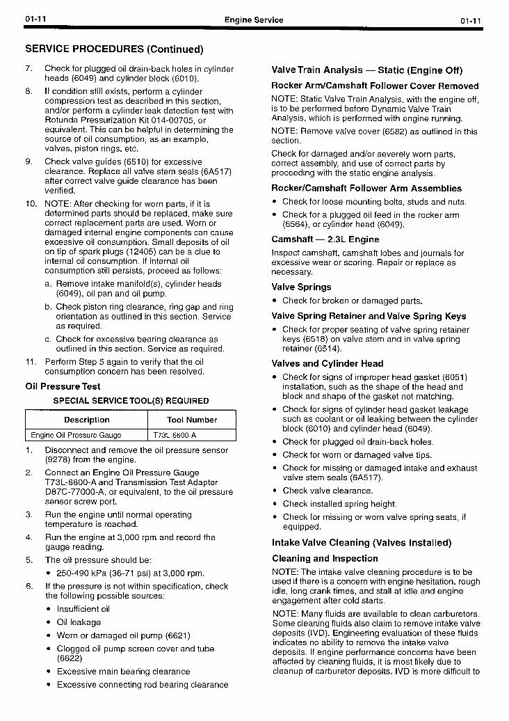
Disconnect and remove the oil pressure sensor (9278) from the engine.
Connect an Engine Oil Pressure Gauge T73L-6600-A and Transmission Test Adapter D87C-77000-A, or equivalent, to the oil pressure sensor screw port.
Run the engine until normal operating temperature is reached.
Run the engine at 3,000 rpm and record the gauge reading.
The oil pressure should be:
l 250-490 kPa (36-71 psi) at 3,000 rpm.
If the pressure is not within specification, check the following possible sources:
l Insufficient oil
l Oil leakage
l Worn or damaged oil pump (6621)
l Clogged oil pump screen cover and tube (6622)
l Excessive main bearing clearance
0 Excessive connecting rod bearing clearance
ValveTrain Analysis - Static (Engine Off)
Rocker Arm/Camshaft Follower Cover Removed
NOTE: Static Valve Train Analysis, with the engine off, is to be performed before Dynamic Valve Train Analysis, which is performed with engine running.
NOTE: Remove valve cover (6582) as outlined in this section.
Check for damaged and/or severely worn parts, correct assembly, and use of correct parts by proceeding with the static engine analysis.
Rocker/Camshaft Follower Arm Assemblies
l Check for loose mounting bolts, studs and nuts.
l Check for a plugged oil feed in the rocker arm (6564), or cylinder head (6049).
Camshaft - 2.3L Engine
Inspect camshaft, camshaft lobes and journals for excessive wear or scoring. Repair or replace as necessary.
Valve Springs
l Check for broken or damaged parts.
Valve Spring Retainer and Valve Spring Keys
l Check for proper seating of valve spring retainer keys (6518) on valve stem and in valve spring retainer (6514).
Valves and Cylinder Head
l Check for signs of improper head gasket (6051) installation, such as the shape of the head and block and shape of the gasket not matching.
l Check for signs of cylinder head gasket leakage such as coolant or oil leaking between the cylinder block (6010) and cylinder head (6049).
l Check for plugged oil drain-back holes.
l Check for worn or damaged valve tips.
l Check for missing or damaged intake and exhaust valve stem seals (6A517).
l Check valve clearance.
0 Check installed spring height.
l Check for missing or worn valve spring seats, if equipped.
Intake Valve Cleaning (Valves Installed)
Cleaning and Inspection
NOTE: The intake valve cleaning procedure is to be used if there is a concern with engine hesitation, rough idle, long crank times, and stall at idle and engine engagement after cold starts.
NOTE: Many fluids are available to clean carburetors. Some cleaning fluids also claim to remove intake valve deposits (IVD). Engineering evaluation of these fluids indicates no ability to remove the intake valve deposits. If engine performance concerns have been affected by cleaning fluids, it is most likely due to cleanup of carburetor deposits. IVD is more difficult to
01-12 Engine Service 01-l 2
SERVICE PROCEDURES (Continued)
remove than carburetor deposits. IVD must be COMPLETELY removed to restore cold start and normal engine performance.
CAUTION:The overuse of cleaning fluids may cause engine damage not covered under warranty.
CAUTION: Only walnut shell blasting using Rotunda 014-00975 Carbon Blaster and Automotive Borescope, or equivalent, is recommended for removing carbon from engine valves with the engine assembled. Other abrasives may cause engine damage on start-up if not completely removed.
1. Perform engine inspection of vacuum lines and wiring.
2. Perform normal engine diagnostics. Check fuel and ignition systems.
3. If normal diagnostics have not resolved the engine performance concerns, proceed with the following IVD inspection steps.
4. Remove any two spark plugs (12405).
5. CAUTION: Do not bump the engine with the remote starter switch or ignition switch with the borescope in the spark plug hole or
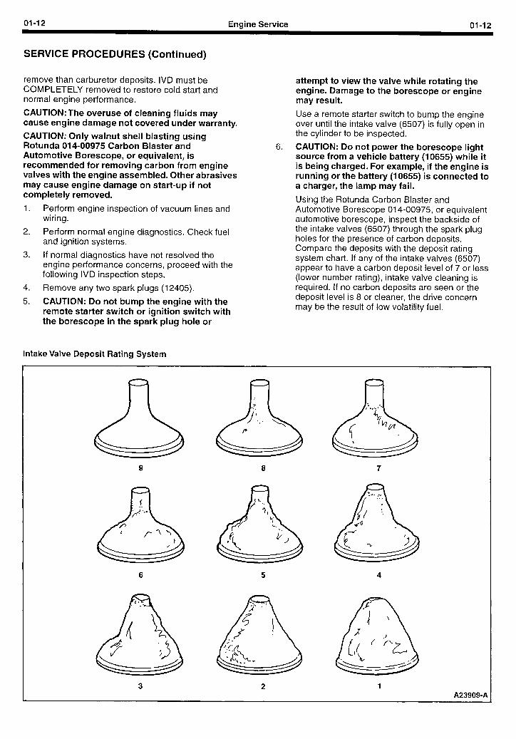
Intake Valve Deposit Rating System
attempt to view the valve while rotating the engine. Damage to the borescope or engine may result.
Use a remote starter switch to bump the engine over until the intake valve (6507) is fully open in the cylinder to be inspected.
6. CAUTION: Do not power the borescope light source from a vehicle battery (10655) while it is being charged. For example, if the engine is running or the battery (10655) is connected to a charger, the lamp may fail.
Using the Rotunda Carbon Blaster and Automotive Borescope 014-00975, or equivalent automotive borescope, inspect the backside of the intake valves (6507) through the spark plug holes for the presence of carbon deposits. Compare the deposits with the deposit rating system chart. If any of the intake valves (6507) appear to have a carbon deposit level of 7 or less (lower number rating), intake valve cleaning is required. If no carbon deposits are seen or the deposit level is 8 or cleaner, the drive concern may be the result of low volatility fuel.
9 8 7
6 5 4
3 2 1 A239094
01-13 Engine Service 01-13
SERVICE PROCEDURES (Continued)
7. Remove the intake manifold assembly as outlined in Section 02.
8.
9.
Remove flex hose and manifold adapter from the hand-held vacuum included with the Rotunda 014-00975 Carbon Blaster and Automotive Borescope. Insert tapered end of vacuum hose into intake port of cylinder head using a twisting motion to ensure a tight fit.
NOTE: Detailed written instructions and a procedural video tape are included with the Rotunda 014-00975 Carbon Blaster and Automotive Borescope. Perform the intake valve carbon cleaning procedure, using the Rotunda 014-00975 Carbon Blaster or equivalent. The intake valves should be in the closed position. Cleaning takes approximately 1 to 1 -i/2 minutes per valve.
10
11
13
Confirm the intake valve (6507) is clean using Rotunda 014-00975, or equivalent automotive borescope.
Using a remote starter switch, bump the engine over until the remaining intake valves to be cleaned, are in the closed position, and clean them as outlined above.
. -. Install the intake manifold as outlined in Section 02.
Camshaft Lobe Lift, 2.3L Overhead Camshaft Engine (Camshaft Installed) This procedure is for checking lift with the camshaft (6251) installed. For checking with camshaft removed, refer to service procedure, Cam Lobe Lift (Camshaft Removed) in this section.
Check the lift of each lobe in make a note of the readings.
consecutive order and
1.
2.
3.
4.
5.
6.
7. 8.
Remove valve cover (6582) as outlined in Section 02.
Remove spark plugs (12405) as outlined in Section 02.
Inspect the camshaft lobes for scoring and signs of abnormal wear.
Lobe pitting, except in the general area of the lobe toe, is not detrimental to the operation of the camshaft. The camshaft should not be replaced unless lobe lift loss has exceeded the specifications or pitting has occurred in the lobe lift area.
Inspect for signs of camshaft bearing wear.
Using ratchet handle and socket on vibration damper bolt, rotate engine so cylinder number one exhaust valve is fully open (heel of cam at top). Install TOOL-4201-C, or equivalent, Dial Indicator with Bracketry, so tip of dial indicator is on heel of cam.
Zero dial indicator.
Slowly rotate engine until tip of dial indicator is on tip of cam and read. This is cam lift.
9. Write down cam lift and repeat for the rest of the cam lobes. If any lobe’s lift is below the minimum lift specified in Section 02, replace the camshaft.
Hydraulic Valve Tappet/Lash Adjuster
The hydraulic lash adjusters used in the overhead cam 2.3L engine are zero-lash hydraulic devices similar in construction and operation to the hydraulic valve tappets (6500) used on push rod engines. They are cleaned, inspected and checked in the same manner as hydraulic valve tappets The instructions below apply equally to the lash adjuster and the valve tappet.
Hydraulic tappet noise may be caused by any of the following:
1. Excessive collapsed tappet gap
2. Sticking tappet plunger
3. Tappet check valve not functioning properly
4. Air in lubrication system
5. Leak-down rate too rapid
6. Excessive valve guide wear
Excessive collapsed tappet gap may be caused by loose valve train parts such as wear of tappet face, worn roller finger follower (6529), or worn valve tip. With valve tappet (6500) collapsed, check gap between valve tip and roller finger follower to determine if any other valve train parts are damaged, or worn. Replace any worn or damaged parts.
A sticking tappet plunger may be caused by dirt, chips, or varnish inside the tappet. The sticking can be corrected by disassembling the valve tappet and removing the dirt, chips or varnish that are causing the condition.
A tappet check valve that is not functional may be caused by an obstruction such as dirt or chips preventing it from closing when operated, or it may be caused by a broken check valve spring within the tappet.
Air bubbles in the lubrication system will prevent the valve tappet from supporting the valve spring load and may be caused by an oil level that is too high or too low, or by air being drawn into the system through a hole, crack or leaking gasket on the oil pump screen cover and tube (6622).
If the leakdown time is below the specified time for used valve tappets, noisy operation may result. If no other cause for noisy valve tappets can be found, the leakdown rate should be checked, and any outside the specification should be replaced.
Camshaft End Play CAUTION: Prying against the camshaft sprocket (6256) with valve train load on the camshaft (6251), can break or damage the camshaft sprocket. Therefore, on 2.3L engines, remove the cam followers as outlined in Section 02.
After checking camshaft end play, reinstall or retighten valve train components as outlined in Section 02.
01-14 Engine Service 01-14
SERVICE PROCEDURES (Continued)
Timing Belt (2.3L) NOTE: If the timing belt has greater than 3,000 hours of use, the timing belt will need to be replaced. Refer to Section 02 for service procedures.
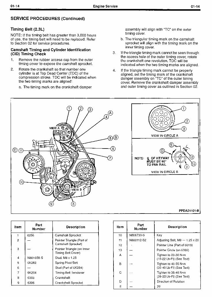
Camshaft Timing and Cylinder Identification (CID) Timing Check 1. Remove the rubber access cap from the outer
timing cover to expose the camshaft sprocket.
2. Rotate the crankshaft so that number one cylinder is at Top Dead Center (TDC) of the compression stroke. TDC will be indicated when
assembly will align with “TC” on the outer timing cover.
b. The triangular timing mark on the camshaft sprocket will align with the timing mark on the inner timing cover.
3. If the triangle timing mark cannot be seen through the access hole of the outer timing cover, rotate the crankshaft one revolution. TDC will be indicated when the two timing marks are aligned.
4. If the triangle timing mark cannot be properly aligned, set the timing mark of the crankshaft damper assemblv on “TC” of the outer timing
the two timing marks are aligned: cover. Remove the crankshaft damper assembly a. The timing mark on the crankshaft damper and outer timing cover as outlined in Section 02.
0 C
VIEW IN CIRCLE A
NOTE: B TO PAN RAIL
VIEW IN CIRCLE 8
d 9 0 8
PPDA21101-6 J
Item Part
Number
6256
N801658-S
6K282
6K254
6303
6306
Description Item
Camshaft Sprocket
Pointer Triangle (Part of Camshaft Sprocket)
Pointer Triangle (on Inner Timing Belt Cover)
Stud, M8 x 1.25
Spring Pivot Bolt
Stud (Part of 6K254)
Timing Belt Tensioner
Crankshaft
Crankshaft Sprocket
IO
11
12
13
A
B
C
D
E
Part Number
N806700-S
N800112-52
Description
Key
Adjusting Bolt, M8 - 1.25 x 20
Pointer Line (Part of 6019)
Pointer Circle (on 6306)
Tighten to 20-30 Nom (15-22 Lb-Ft) (See Text)
Tighten to 40-55 N*m (30-40 Lb-Ft) (See Text)
Tighten to 35-45 Nom (26-33 Lb-Ft) (See Text)
Direction of Rotation
29”
01-15 Engine Service 0145
SERVICE PROCEDURES (Continued)
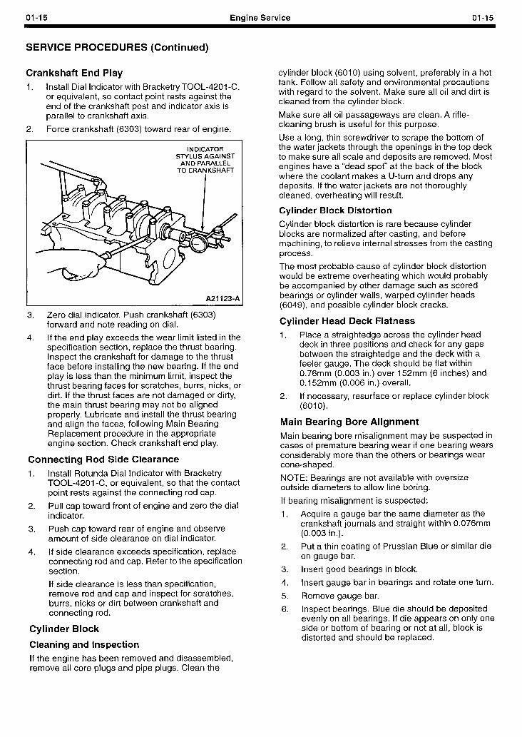
Crankshaft End Play 1. Install Dial Indicator with Bracketry TOOL-4201 -C,
or equivalent, so contact point rests against the end of the crankshaft post and indicator axis is parallel to crankshaft axis.
2. Force crankshaft (6303) toward rear of engine.
INDICATOR STYLUS AGAINST
AND PARALLEL
A211234
3. Zero dial indicator. Push crankshaft (6303) forward and note reading on dial.
4. If the end play exceeds the wear limit listed in the specification section, replace the thrust bearing. Inspect the crankshaft for damage to the thrust face before installing the new bearing. If the end play is less than the minimum limit, inspect the thrust bearing faces for scratches, burrs, nicks, or dirt. If the thrust faces are not damaged or dirty, the main thrust bearing may not be aligned properly. Lubricate and install the thrust bearing and align the faces, following Main Bearing Replacement procedure in the appropriate engine section. Check crankshaft end play. .
Connecting Rod Side Clearance 1. Install Rotunda Dial Indicator with Bracketry
TOOL-4201-C, or equivalent, so that the contact point rests against the connecting rod cap.
2. Pull cap toward front of engine and zero the dial indicator.
3. Push cap toward rear of engine and observe amount of side clearance on dial indicator.
4. If side clearance exceeds specification, replace connecting rod and cap. Refer to the specification section.
If side clearance is less than specification, remove rod and cap and inspect for scratches, burrs, nicks or dirt between crankshaft and connecting rod.
Cylinder Block
Cleaning and Inspection
If the engine has been removed and disassembled, remove all core plugs and pipe plugs. Clean the
cylinder block (6010) using solvent, preferably in a hot tank. Follow all safety and environmental precautions with regard to the solvent. Make sure all oil and dirt is cleaned from the cylinder block.
Make sure all oil passageways are clean. A rifle- cleaning brush is useful for this purpose.
Use a long, thin screwdriver to scrape the bottom of the water jackets through the openings in the top deck to make sure all scale and deposits are removed. Most engines have a “dead spot” at the back of the block where the coolant makes a U-turn and drops any deposits. If the water jackets are not thoroughly cleaned, overheating will result.
Cylinder Block Distortion
Cylinder block distortion is rare because cylinder blocks are normalized after casting, and before machining, to relieve internal stresses from the casting process.
The most probable cause of cylinder block distortion would be extreme overheating which would probably be accompanied by other damage such as scored bearings or cylinder walls, warped cylinder heads (6049) and possible cylinder block cracks.
Cylinder Head Deck Flatness 1. Place a straightedge across the cylinder head
deck in three positions and check for any gaps between the straightedge and the deck with a feeler gauge. The deck should be flat within 0.76mm (0.003 in.) over 152mm (6 inches) and 0.152mm (0.006 in.) overall.
2. If necessary, resurface or replace cylinder block (6010).
Main Bearing Bore Alignment
Main bearing bore misalignment may be suspected in cases of premature bearing wear if one bearing wears considerably more than the others or bearings wear cone-shaped.
NOTE: Bearings are not available with oversize outside diameters to allow line boring.
If bearing misalignment is suspected:
1. Acquire a gauge bar the same diameter as the crankshaft journals and straight within 0.076mm (0.003 in.).
2. Put a thin coating of Prussian Blue or similar die on gauge bar.
3. Insert good bearings in block.
4. Insert gauge bar in bearings and rotate one turn.
5. Remove gauge bar.
6. Inspect bearings. Blue die should be deposited evenly on all bearings. If die appears on only one side or bottom of bearing or not at all, block is distorted and should be replaced.
01-16 Engine Service 01-16
SERVICE PROCEDURES (Continued)
Cylinder Walls, Refinishing
Cleaning
If the entire engine has NOT been disassembled, clean the individual cylinder bore(s) with a cloth soaked in solvent. Dry with a clean, lint-free cloth.
If the entire engine HAS been disassembled, refer to Cylinder Block Cleaning in this section.
After any cylinder bore service operation, such as honing or deglazing, clean the bore(s) with soap or detergent and water. Then thoroughly rinse the bore(s) with clean water to remove the soap or detergent, and wipe the bore(s) dry with a clean lint-free cloth. Finally, wipe the bore(s) with a clean cloth dipped in X0-1 OW30-QSP or -DSP, or equivalent, motor oil meeting Ford specification ESE-M2C153-E.
Inspection
Before removing the piston (6108):
1. Check the amount of ridge at the top of the bore. A thick ridge is a sign of considerable wear.
2. Look for signs of coolant in the bore, especially rust on the bore surface indicating possible leaking head gasket or a crack in the cylinder bore.
3. Check the top of the piston for possible oversize. If oversize pistons have been installed, the oversize will be stamped in the top of the piston (6110).
After the piston is removed and the bore cleaned:
4.
5.
6.
Look for scoring. These are parallel gouges usually on the piston thrust side, that is, at right angles to the piston pin. If scored, the cylinder will have to be refinished.
Look for cracks. If unsure about a crack, tiny cracks may be detected by coating the bore with a mixture of 25 percent kerosene and 75 percent light engine oil. Wipe the bore dry and immediately apply a coating of zinc oxide dissolved in wood alcohol. Do not use rubbing alcohol as a substitute. If cracks are present, the coating will become discolored at the damaged area. Replace the cylinder block if it is cracked. Magnafluxing may also be used.
Check for cylinder wall glazing. When refinished, the cylinder bore is given a slightly rough finish with a cylinder hone to help seat the new piston rings. This finish is worn away as the rings and cylinder bore “mate” and the bore becomes glassy smooth. If the engine has been run enough for this to have happened, the cylinder will at least have to be honed to seat the new rings on the piston. New rings should be installed when the piston is removed and reinstalled because piston rings are given a special finish by the factory to help them wear-in and seat. In seating, the special finish is worn off. Reusing piston rings will result in high oil consumption.
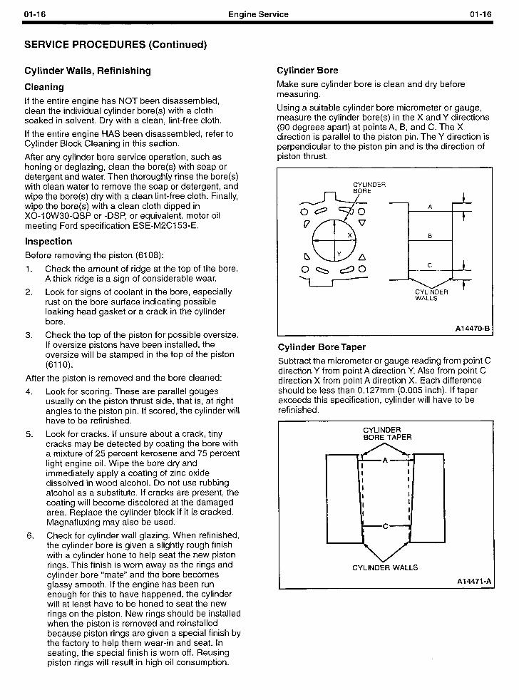
Cylinder Bore
Make sure cylinder bore is clean and dry before measuring.
Using a suitable cylinder bore micrometer or gauge, measure the cylinder bore(s) in the X and Y directions (90 degrees apart) at points A, B, and C. The X direction is parallel to the piston pin. The Y direction is perpendicular to the piston pin and is the direction of piston thrust.
CYLINDER
1 . . A
t
B
CYLINDER WALLS
Al 4470-B
Cylinder Bore Taper
Subtract the micrometer or gauge reading from point C direction Y from point A direction Y. Also from point C direction X from point A direction X. Each difference should be less than 0.127mm (0.005 inch). If taper exceeds this specification, cylinder will have to be refinished.
CYLINDER BORE TAPER
CYLINDER WALLS
Al 4471 -A
01-17 Engine Service 01-17
SERVICE PROCEDURES (Continued)
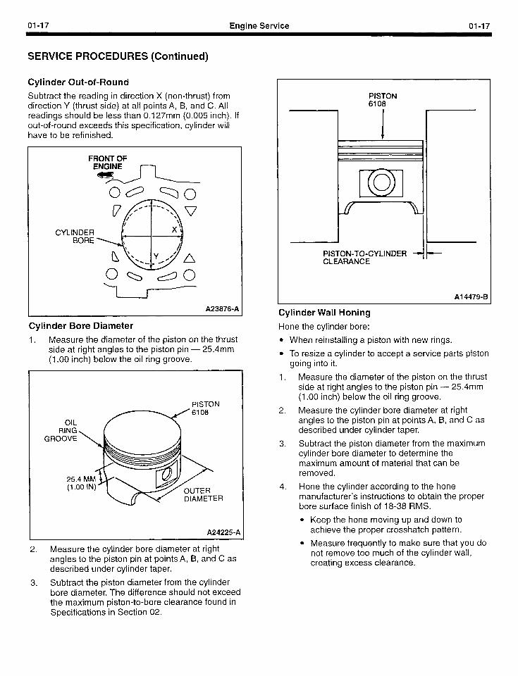
Cylinder Out-of-Round
Subtract the reading in direction X (non-thrust) from direction Y (thrust side) at all points A, B, and C. All readings should be less than 0.127mm (0.005 inch). If out-of-round exceeds this specification, cylinder will have to be refinished.
CYLI
FRONT OF
Egz
NDER BORE
A23876-A
Cylinder Bore Diameter
1. Measure the diameter of the piston on the thrust side at right angles to the piston pin - 254mm (1 .OO inch) below the oil ring groove.
GR
PISTON
:I3
A24225-A
2. Measure the cylinder bore diameter at right angles to the piston pin at points A, B, and C as described under cylinder taper.
3. Subtract the piston diameter from the cylinder bore diameter. The difference should not exceed the maximum piston-to-bore clearance found in Specifications in Section 02.
PISTON 6108
PISTON-TO-CYLINDER 1 f-- CLEARANCE
Al 4479-B
Cylinder Wall Honing
Hone the cylinder bore:
l When reinstalling a piston with new rings.
l To resize a cylinder to accept a service parts piston going into it.
1. Measure the diameter of the piston on the thrust side at right angles to the piston pin - 254mm (1 .OO inch) below the oil ring groove.
2. Measure the cylinder bore diameter at right angles to the piston pin at points A, B, and C as described under cylinder taper.
3. Subtract the piston diameter from the maximum cylinder bore diameter to determine the maximum amount of material that can be removed.
4. Hone the cylinder according to the hone manufacturer’s instructions to obtain the proper bore surface finish of 18-38 RMS.
l Keep the hone moving up and down to achieve the proper crosshatch pattern.
l Measure frequently to make sure that you do not remove too much of the cylinder wall, creating excess clearance.
01-18 Engine Service 01-18
SERVICE PROCEDURES (Continued)
Engine Block Plugs
SPECIAL SERVICE TOOL(S) REQUIRED
Description
Impact Slide Hammer
Impact Slide Hammer
Removal and Installation
Tool Number
T59L-100-B
T50T-100-A
To remove a large core plug, drill a 12.70mm (l/2 inch) hole in the center of the plug and remove with an Impact Slide Hammer T59L-100-B or T50T-100-A or pry it out with a large drift punch. On a small core plug, drill a 6.35mm (l/4 inch) hole in the center of the plug and pry it out with a small pin punch. Clean and inspect the plug bore.
Prior to installing a core plug, the plug bore should be inspected for any damage that would interfere with the proper sealing of the plug. If the bore is damaged, it will be necessary to true the surface by boring for the next specified oversize plug.
Oversize plugs are identified by the OS stamped in the flat located on the cup side of the plug.
Coat the plug and/or bore lightly with an oil-resistant (oil galley) Stud and Bearing Mount EOAZ-19554-BA, or equivalent, meeting Ford specification WSK-M2G349-Al or Threadlock 262 E2FZ-19554-B, or equivalent, meeting Ford specification WSK-M2G351 -A6, and install it following the procedure for cup-type or expansion-type below:
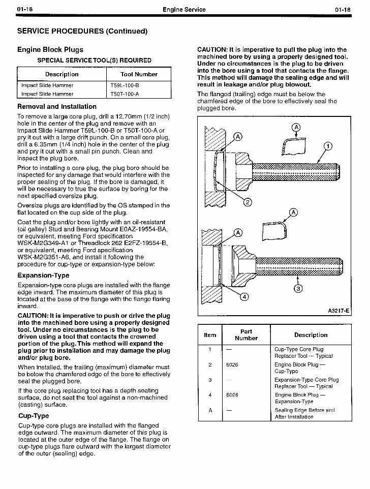
Expansion-Type
Expansion-type core plugs are installed with the flange edge inward. The maximum diameter of this plug is located at the base of the flange with the flange flaring inward.
CAUTION: It is imperative to push or drive the plug into the machined bore using a properly designed tool. Under no circumstances is the plug to be driven using a tool that contacts the crowned portion of the plug.This method will expand the plug prior to installation and may damage the plug and/or plug bore.
When installed, the trailing (maximum) diameter must be below the chamfered edge of the bore to effectively seal the plugged bore.
If the core plug replacing tool has a depth seating surface, do not seat the tool against a non-machined (casting) surface.
Cup-Type
Cup-type core plugs are installed with the flanged edge outward. The maximum diameter of this plug is located at the outer edge of the flange. The flange on cup-type plugs flare outward with the largest diameter of the outer (sealing) edge.
CAUTION: It is imperative to pull the plug into the machined bore by using a properly designed tool. Under no circumstances is the plug to be driven into the bore using a tool that contacts the flange. This method will damage the sealing edge and will result in leakage and/or plug blowout.
The flanged (trailing) edge must be below the chamfered edge of the bore to effectively seal the plugged bore.
A321 7-E
Item Part Number Description
1 - Cup-Type Core Plug Replacer Tool - Typical
2 6026 Engine Block Plug - Cup-Type
3 - Expansion-Type Core Plug Replacer Tool - Typical
4 6026 Engine Block Plug - Expansion-Type
A - Sealing Edge Before and After Installation
01-19 Enaine Service 01-19
SERVICE PROCEDURES (Continued)
Crankshaft Main and Connecting Rod Bearings
Cleaning
NOTE: Do not scrape gum or varnish deposits from the bearing shells.
Bearings that are to be reused should be identified so they can be installed in their original locations.
Clean the bearing inserts and caps thoroughly in solvent, and dry them with compressed air.
Inspection
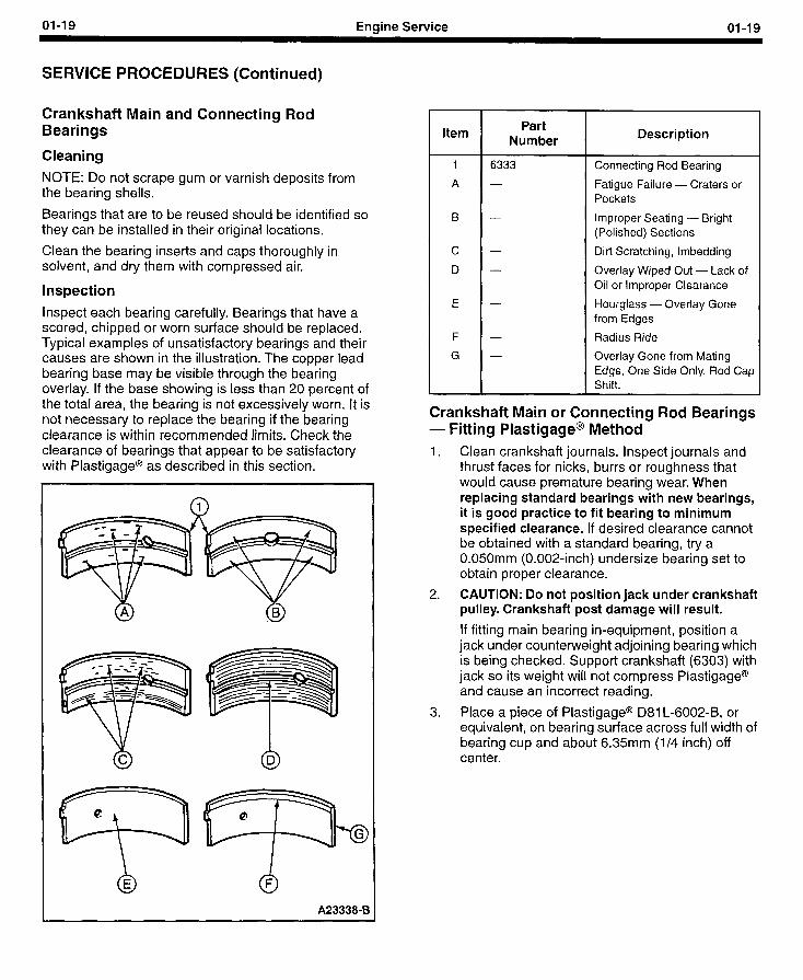
Inspect each bearing carefully. Bearings that have a scored, chipped or worn surface should be replaced. Typical examples of unsatisfactory bearings and their causes are shown in the illustration. The copper lead bearing base may be visible through the bearing overlay. If the base showing is less than 20 percent of the total area, the bearing is not excessively worn. It is not necessary to replace the bearing if the bearing clearance is within recommended limits. Check the clearance of bearings that appear to be satisfactory with Plastigage@ as described in this section.
n
00 A2333843
Item Part
Number Description
1 6333 Connecting Rod Bearing
A - Fatigue Failure - Craters or Pockets
B - Improper Seating - Bright (Polished) Sections
c - Dirt Scratching, lmbedding
D - Overlay Wiped Out - Lack of Oil or Improper Clearance
E - Hourglass - Overlay Gone from Edges
F - Radius Ride
G - Overlay Gone from Mating Edge, One Side Only. Rod Cap Shift.
Crankshaft Main or Connecting Rod Bearings - Fitting Plastigage@ Method 1. Clean crankshaft journals. Inspect journals and
thrust faces for nicks, burrs or roughness that would cause premature bearing wear. When replacing standard bearings with new bearings, it is good practice to fit bearing to minimum specified clearance. If desired clearance cannot be obtained with a standard bearing, try a 0.050mm (0.002-inch) undersize bearing set to obtain proper clearance.
2. CAUTION: Do not position jack under crankshaft pulley. Crankshaft post damage will result.
If fitting main bearing in-equipment, position a jack under counterweight adjoining bearing which is being checked. Support crankshaft (6303) with jack so its weight will not compress Plastigage@ and cause an incorrect reading.
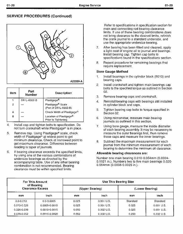
3. Place a piece of Plastigage@ D81 L-6002-B, or equivalent, on bearing surface across full width of bearing cup and about 6.35mm (l/4 inch) off center.
1
01-20 Engine Service 01-20
SERVICE PROCEDURES (Continued)
A233390A
Item Part
Number Description
1 D81 L-6002-B Plastigage@
2 - Plastigage@ Scale (Part of 081 L-6002-B)
A - Check Width of Plastigage@
B - Location of Plastigage@ Prior to Tightening
4. Install cap and tighten bolts to specification. Do not turn crankshaft while Plastigage@ is in place.
5. Remove cap. Using Plastigage@ scale, check width of Plastigage@ at widest point to get minimum clearance. Check at narrowest point to get maximum clearance. Difference between reading is taper of journals.
6. If bearing clearance exceeds the specified limits, try using one of the various combinations of undersize bearings as directed by the accompanying table. Use of any other bearing combination is not recommended. Bearing clearance must be within specified limits.
Refer to specifications in specification section for main and connecting rod bearing clearance limits. If use of these bearing combinations does not bring clearance to the desired limits, refinish the crank journal to a standard undersize, and use the appropriate undersize bearing.
7. After bearing has been fitted and cleaned, apply a light coat of engine oil to journal and bearings. Install bearing cap. Tighten cap bolts to specifications found in the specifications section.
8. Repeat procedure for remaining bearings that require replacement.
Bore Gauge Method
1.
2.
3.
4.
5.
6.
7.
8.
Install bearings in the cylinder block (6010) and bearing caps.
Install crankshaft and tighten main bearings cap bolts to the specified torque as outlined in Section 02.
Remove bearing caps and crankshaft.
Reinstall bearing caps with bearings still installed in cylinder block and caps.
Tighten bearing cap bolts to torque specified in Section 02.
Using micrometer, measure main bearing journals as outlined in this section.
Using bore gauge, measure the inside diameter of each bearing assembly. It may be necessary to measure the outer bearings first, then remove those caps and measure the inner bearings.
Subtract the maximum measurement for each journal from the minimum measurement of each bearing to determine the minimum oil clearance.
Allowable bearing clearances are:
Number one main bearing 0.01 O-0.054mm (0.0004- 0.0021 in.). Numbers two to five main bearings 0.020- 0.064mm (0.0008-0.0025 in.).
,
For This Amount of Bearing
Clearance Excess
mm inch
0.0-0.013 0.0-0.0005
0.013-0.026 0.0005-0.0010
0.026-0.039 0.0010-0.0015
0.039-0.052 0.0015-0.0020
Use This Bearing Size
(Upper Bearing) (Lower Bearing)
mm inch mm inch
0.025 0.001 U.S. Standard Standard
0.025 0.001 U.S. 0.025 0.001 U.S.
0.050 0.002 U.S. 0.025 0.001 U.S.
0.050 0.002 U.S. 0.050 0.002 U.S.
01-21 Engine Service 01-21
SERVICE PROCEDURES (Continued)
Crankshaft
Cleaning
CAUTION: Handle the crankshaft (6303) with care to avoid possible damage to the finished surfaces.
Clean the crankshaft with solvent, then blow out all oil passages with compressed air.
Inspection
Measure the diameter of each journal in at least four places to determine an out-of-round, taper or undersize condition. For specifications, refer to the specification section.
Crankshaft Runout
NOTE: Check crankshaft journals for out-of-round before checking runout, or an out-of-round condition on the center journal could be confused as excess runout.
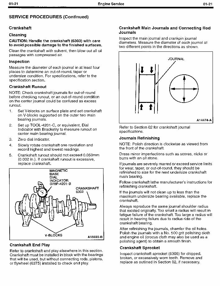
1. Set V-blocks on surface plate and set crankshaft on V-blocks supported on the outer two main bearing journals.
2. Set up TOOL-4201 -C, or equivalent, Dial Indicator with Bracketry to measure runout on center main bearing journal.
3. Zero dial indicator.
4. Slowly rotate crankshaft one revolution and record highest and lowest readings.
5. Crankshaft runout should not exceed 0.050mm (0.002 in.). If crankshaft runout is excessive, replace crankshaft.
MAGNETIC BASE DIAL
k INDICATOR D78P-4201 -B I
V-BLOCKS Al 6693-B
Crankshaft End Play
Refer to crankshaft end play elsewhere in this section. Crankshaft must be installed in block with the bearings that will be used, but without connecting rods, pistons, or flywheel (6375) installed to check end play.
Crankshaft Main Journals and Connecting Rod Journals
Inspect the main journal and crankpin journal diameters. Measure the diameter of each journal at two different points in the directions as shown.
JOURNAL
Al 4474-A
Refer to Section 02 for crankshaft journal specifications.
Journals Refinishing
NOTE: Polish direction is clockwise as viewed from the front of the crankshaft.
Dress minor imperfections such as scores, nicks or burrs with an oil stone.
If journals are severely marred or exceed service limits for wear, taper, or out-of-round, they should be refinished to size for the next undersize crankshaft main bearing.
Follow crankshaft lathe manufacturer’s instructions for refinishing crankshaft.
If the journals will not clean up to less than the maximum undersize bearing available, replace the crankshaft.
Always reproduce the same journal shoulder radius that existed originally. Too small a radius will result in fatigue failure of the crankshaft. Too large a radius will result in bearing failure due to radius ride of the crankshaft bearing.
After refinishing the journals, chamfer the oil holes. Polish the journals with a No. 500 grit polishing cloth and engine oil (crocus cloth may also be used as a polishing agent) to obtain a smooth finish.
Crankshaft Sprocket
Inspect crankshaft sprocket (6306) for chipped, broken, or excessively worn teeth. Remove and replace as outlined in Section 02, if necessary.
01-22 Engine Service 01-22
SERVICE PROCEDURES (Continued)
Pistons, Piston Pins and Piston Rings
Cleaning 1. Clean piston (6108) using suitable solvent.
2. Using a putty knife or scraper, clean carbon off of the top of the piston.
3. Do not use a power wire brush to clean the piston skirt, crown, or piston ring grooves as it will remove metal.
4. If using a ring groove scraper, be careful not to remove metal from the piston ring lands.
inspection Inspect for:
1. A hole or crack in top of piston (6110) caused by pre-ignition or foreign object damage.
2. Excess wear in ring lands indicated by visible steps worn in ring lands.
3. Scoring or gouges on piston skirt or crown.
4. Looseness between piston (6110) and piston pin.
Pistons - Fitting
SPECIAL SERVICE TOOL(S) REQUIRED
Description Tool Number
Engine Cylinder Hone Set T73L-6011 -A
NOTE: There is one size piston, available through Service Parts, that can be used when the original standard-size bore shows little wear and can be cleaned up. The dimensions of this piston can fall anywhere between 95.968-95.993 mm (3.7783- 3.7792 in.). This piston must be select-fitted to the cylinder bore. It will likely be necessary to hone the cylinder bore in order to produce the specified piston- to-bore clearance.
To determine if a Service Parts piston can be installed, and if so, to fit the Service Parts piston, proceed as follows:
1. Measure the cylinder bore as outlined in this section under Cylinder Bore Measuring. If the cylinder bore is not damaged, and wear, taper and out-of-round are within specifications listed in Section 02, the cylinder bore may be cleaned up and a new Service Parts piston select-fitted to the refurbished bore.
2. Hone the cylinder, if necessary, to restore a proper crosshatch pattern so new rings can seat. Remove as little of the cylinder wall as possible.
3. After any necessary honing of the cylinder bore, check that the piston-to-bore clearance is to specification. If the clearance is too great, measure the cylinder bore diameter to determine if it falls within the Service Limits found in the Specifications in Section 02. If the bore diameter falls within the Service Limits, it will be possible to select-fit a new Service piston. If the bore diameter exceeds the Service Limits, it will be
necessary to replace the cylinder block assembly. Oversize pistons are not available for this engine.
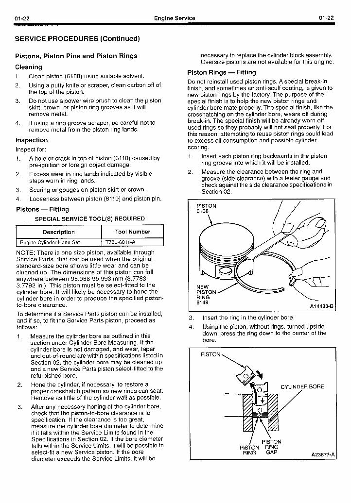
Piston Rings - Fitting Do not reinstall used piston rings. A special break-in finish, and sometimes an anti-scuff coating, is given to new piston rings by the factory. The purpose of the special finish is to help the new piston rings and cylinder bore mate properly. The special finish, like the crosshatching on the cylinder bore, wears off during break-in. The special finish will be already worn off used rings so they probably will not seat,properly. For this reason, attempting to reuse piston rings could lead to excess oil consumption and possible cylinder scoring.
1. Insert each piston ring backwards in the piston ring groove into which it will be installed.
2. Measure the clearance between the ring and groove (side clearance) with a feeler gauge and check against the side clearance specifications in Section 02.
PISTON 6108
RING 6149
Al 4480-B
3. Insert the ring in the cylinder bore.
4. Using the piston, without rings, turned upside down, press the ring down to the center of the bore.
PISTON
,R BORE
/ PISTON PISTON RING
RING GAP A23877-A
01-23 Engine Service 01-23
SERVICE PROCEDURES (Continued)
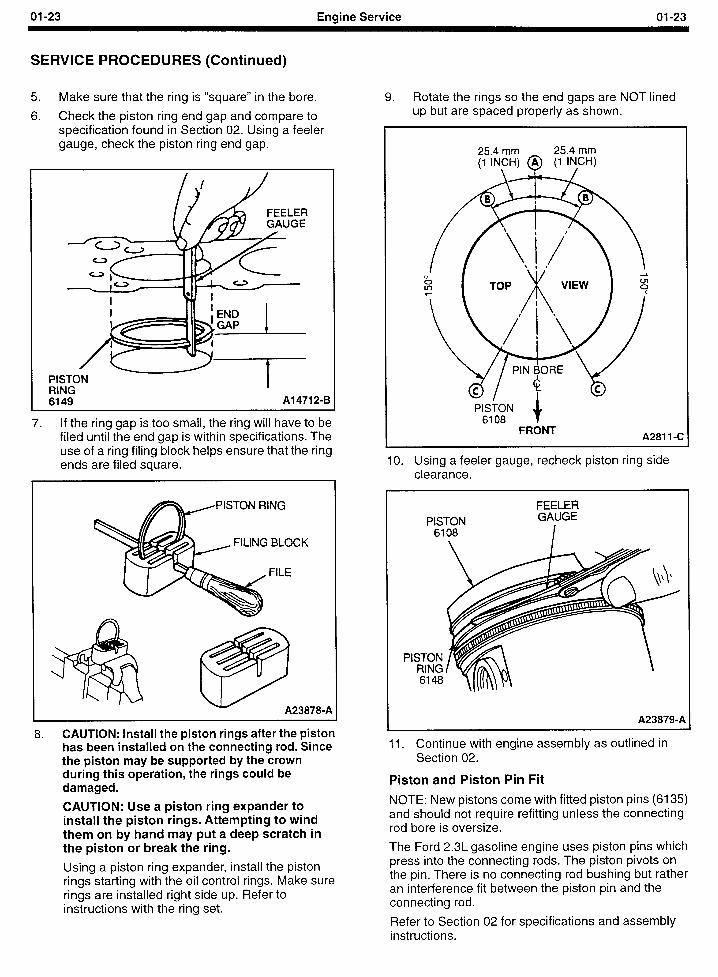
5. Make sure that the ring is “square” in the bore.
6. Check the piston ring end gap and compare to specification found in Section 02. Using a feeler gauge, check the piston ring end gap.
I I I I
i 1 I I
‘ISTON P RING i
6149 Al 4712-B
7. If the ring gap is too small, the ring will have to be filed until the end gap is within specifications. The use of a ring filing block helps ensure that the ring ends are filed square.
FILING BLOCK
A238709A
8. CAUTION: Install the piston rings after the piston has been installed on the connecting rod. Since the piston may be supported by the crown during this operation, the rings could be damaged.
CAUTION: Use a piston ring expander to install the piston rings. Attempting to wind them on by hand may put a deep scratch in the piston or break the ring.
Using a piston ring expander, install the piston rings starting with the oil control rings. Make sure rings are installed right side up. Refer to instructions with the ring set.
9. Rotate the rings so the end gaps are NOT lined up but are spaced properly as shown.
FRONT A281 1 -C
10. Using a feeler gauge, recheck piston ring side clearance.
FEELER
A23879-A
Il. Continue with engine assembly as outlined in Section 02.
Piston and Piston Pin Fit
NOTE: New pistons come with fitted piston pins (6135) and should not require refitting unless the connecting rod bore is oversize.
The Ford 2.3L gasoline engine uses piston pins which press into the connecting rods. The piston pivots on the pin. There is no connecting rod bushing but rather an interference fit between the piston pin and the connecting rod.
Refer to Section 02 for specifications and assembly instructions.
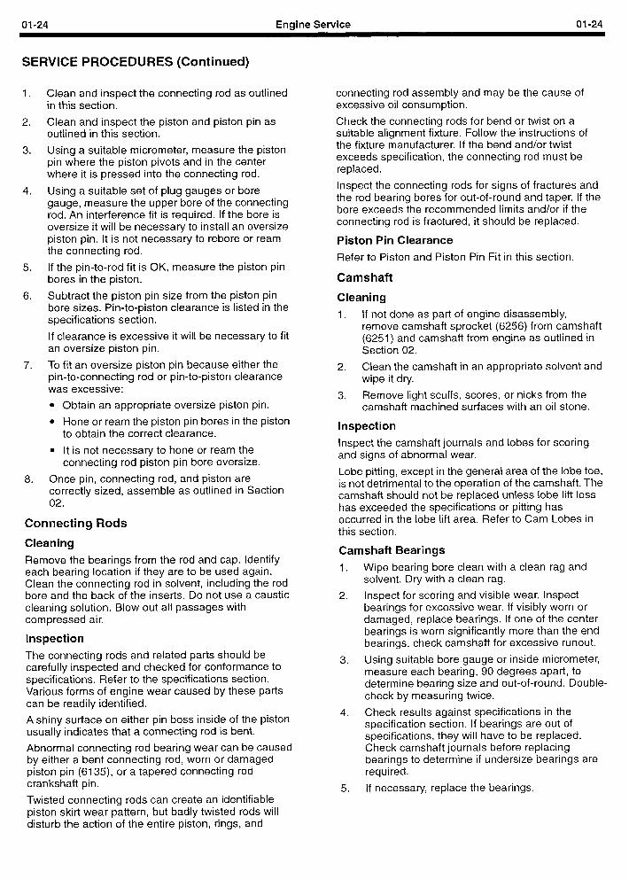
01-24 Engine Service 01-24
SERVICE PROCEDURES (Continued)
1.
2.
3.
4.
5.
6.
7.
8,
Clean and inspect the connecting rod as outlined in this section.
Clean and inspect the piston and piston pin as outlined in this section.
Using a suitable micrometer, measure the piston pin where the piston pivots and in the center where it is pressed into the connecting rod.
Using a suitable set of plug gauges or bore gauge, measure the upper bore of the connecting rod. An interference fit is required. If the bore is oversize it will be necessary to install an oversize piston pin. It is not necessary to rebore or ream the connecting rod.
If the pin-to-rod fit is OK, measure the piston pin bores in the piston.
Subtract the piston pin size from the piston pin bore sizes. Pin-to-piston clearance is listed in the specifications section.
If clearance is excessive it will be necessary to fit an oversize piston pin.
To fit an oversize piston pin because either the pin-to-connecting rod or pin-to-piston clearance was excessive:
l Obtain an appropriate oversize piston pin.
l Hone or ream the piston pin bores in the piston to obtain the correct clearance.
l It is not necessary to hone or ream the connecting rod piston pin bore oversize.
Once pin, connecting rod, and piston are correctly sized, assemble as outlined in Section 02.
Connecting Rods
Cleaning
Remove the bearings from the rod and cap. Identify each bearing location if they are to be used again. Clean the connecting rod in solvent, including the rod bore and the back of the inserts. Do not use a caustic cleaning solution. Blow out all passages with compressed air.
Inspection
The connecting rods and related parts should be carefully inspected and checked for conformance to specifications. Refer to the specifications section. Various forms of engine wear caused by these parts can be readily identified.
A shiny surface on either pin boss i nside of the usually indicates that a connecting rod is bent.
ston
Abnormal connecting rod bearing wear can be caused by either a bent connecting rod, worn or damaged piston pin (6135), or a tapered connecting rod crankshaft pin.
Twisted connecting rods can create an identifiable piston skirt wear pattern, but badly twisted rods will disturb the action of the entire piston, rings, and
connecting rod assembly and may be the cause of excessive oil consumption.
Check the connecting rods for bend or twist on a suitable alignment fixture. Follow the instructions of the fixture manufacturer. If the bend and/or twist exceeds specification, the connecting rod must be replaced.
Inspect the connecting rods for signs of fractures and the rod bearing bores for out-of-round and taper. If the bore exceeds the recommended limits and/or if the connecting rod is fractured, it should be replaced.
Piston Pin Clearance
Refer to Piston and Piston Pin Fit in this section.
Camshaft
Cleaning
1. If not done as part of engine disassembly, remove camshaft sprocket (6256) from camshaft (6251) and camshaft from engine as outlined in Section 02.
2. Clean the camshaft in an appropriate solvent and wipe it dry.
3. Remove light scuffs, scores, or nicks from the camshaft machined surfaces with an oil stone.
Inspection
Inspect the camshaft journals and lobes for scoring and signs of abnormal wear.
Lobe pitting, except in the general area of the lobe toe, is not detrimental to the operation of the camshaft. The camshaft should not be replaced unless lobe lift loss has exceeded the specifications or pitting has occurred in the lobe lift area. Refer to Cam Lobes in this section.
Camshaft Bearings
1.
2.
3.
4.
5,
Wipe bearing bore clean with a clean rag and solvent. Dry with a clean rag.
Inspect for scoring and visible wear. Inspect bearings for excessive wear. If visibly worn or damaged, replace bearings. If one of the center bearings is worn significantly more than the end bearings, check camshaft for excessive runout.
Using suitable bore gauge or inside micrometer, measure each bearing, 90 degrees apart, to determine bearing size and out-of-round. Double- check by measuring twice.
Check results against specifications in the specification section. If bearings are out of specifications, they will have to be replaced. Check camshaft journals before replacing bearings to determine if undersize bearings are required.
If necessary, replace the bearings.
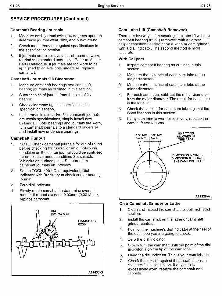
01-25 Engine Service 01-25
SERVICE PROCEDURES (Continued)
Camshaft Bearing Journals
1. Measure each journal twice, 90 degrees apart, to determine journal wear, size, and out-of-round.
2. Check measurements against specifications in the specification section.
3. If journals are excessively out-of-round or worn, regrind to a standard undersize. Refer to Master Parts Catalogue. If journals are too worn to be refinished to an available undersize, replace camshaft.
Camshaft Journals Oil Clearance
1. Measure camshaft bearings and camshaft bearing journals as outlined in this section.
2. Subtract size of journal from the size of its bearing.
3. Check clearance against specifications in specification section.
4. If clearance is excessive, but camshaft journals are within specifications, simply install new bearings. If both bearings and journals are worn, turn camshaft journals to a standard undersize and install new undersize bearings.
Camshaft Runout
1. NOTE: Check camshaft journals for out-of-round before checking for runout, or an out-of-round condition on the center journal could be confused for an excess runout condition. Set suitable V-blocks on surface plate. Support outer camshaft journals on V-blocks.
2. Set up TOOL-4201-C, or equivalent, Dial Indicator with Bracketry to check center bearing journal.
3. Zero dial indicator.
4. Slowly rotate camshaft to determine overall runout. If runout exceeds 0.03mm (0.0012 in.), replace camshaft.
n DIAL INDICATOR
Al 4453-B
Cam Lobe Lift (Camshaft Removed)
There are two ways of measuring cam lobe lift with the camshaft bearing (6261) removed: with a vernier caliper camshaft bearing or on a lathe or cam grinder with a dial indicator. The second method is more accurate.
With Calipers
1. Inspect camshaft bearing as outlined in this section.
2. Measure the distance of each cam lobe at the major diameter.
3. Measure the distance of each cam lobe at the minor diameter.
4. For each cam lobe, subtract the minor diameter from the major diameter. The result for each lobe is the lobe lift.
5. Check the lobe lift for each cam lobe against the Specifications in this section.
6. If any cam lobe is worn excessively, replace the camshaft and tappets.
6.35 MM 6.35 MM NO Pi-lTlNG
li”CHff4 lN;zf
DIMENSION A MINUS DIMENSION B EQUALS
THE CAM LOBE LIFT
A
A21 328-A
On a Camshaft Grinder or Lathe
1. Clean and inspect the camshaft as outlined in this section.
2. Install the camshaft on the lathe or camshaft grinder centers.
3. Position the machine’s dial indicator at the heel of the cam lobe you are going to check.
4. Zero the dial indicator.
5. Slowly turn the camshaft until the point of the dial indicator is on the tip of the cam lobe.
6. Read the dial indicator. This is your cam lobe lift.
7. Check the lobe lift against the specifications in the specifications section. If any cam is excessively worn, replace the camshaft and tappets.
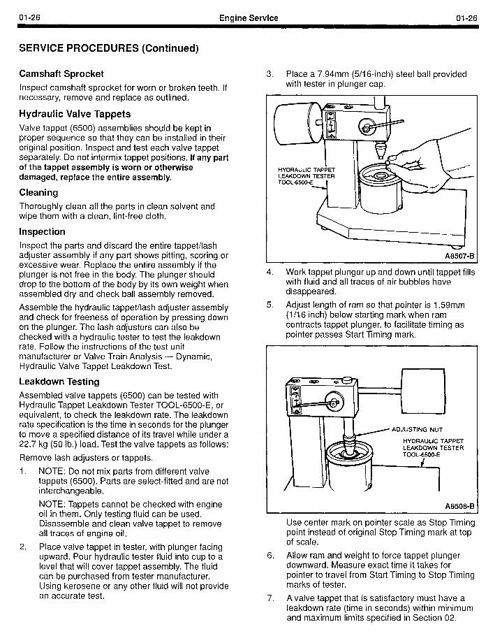
01-26 Engine Service 01-26
SERVICE PROCEDURES (Continued)
Camshaft Sprocket Inspect camshaft sprocket for worn or broken teeth. If necessary, remove and replace as outlined.
Hydraulic Valve Tappets Valve tappet (6500) assemblies should be kept in proper sequence so that they can be installed in their original position. Inspect and test each valve tappet separately. Do not intermix tappet positions. If any part of the tappet assembly is worn or otherwise damaged, replace the entire assembly.
Cleaning Thoroughly clean all the parts in clean solvent and wipe them with a clean, lint-free cloth.
Inspection Inspect the parts and discard the entire tappet/lash adjuster assembly if any part shows pitting, scoring or excessive wear. Replace the entire assembly if the plunger is not free in the body. The plunger should drop to the bottom of the body by its own weight when assembled dry and check ball assembly removed.
Assemble the hydraulic tappet/lash adjuster assembly and check for freeness of operation by pressing down on the plunger. The lash adjusters can also be checked with a hydraulic tester to test the leakdown rate. Follow the instructions of the test unit manufacturer or Valve Train Analysis - Dynamic, Hydraulic Valve Tappet Leakdown Test.
Leakdown Testing Assembled valve tappets (6500) can be tested with Hydraulic Tappet Leakdown Tester TOOL-6500-E, or equivalent, to check the leakdown rate. The leakdown rate specification is the time in seconds for the plunger to move a specified distance of its travel while under a 22.7 kg (50 lb.) load. Test the valve tappets as follows:
Remove lash adjusters or tappets.
1. NOTE: Do not mix parts from different valve tappets (6500). Parts are select-fitted and are not interchangeable.
NOTE: Tappets cannot be checked with engine oil in them. Only testing fluid can be used. Disassemble and clean valve tappet to remove all traces of engine oil.
2. Place valve tappet in tester, with plunger facing upward. Pour hydraulic tester fluid into cup to a level that will cover tappet assembly. The fluid can be purchased from tester manufacturer. Using kerosene or any other fluid will not provide an accurate test.
3. Place a 7.94mm (5/l 6-inch) steel ball provided with tester in plunger cap.
A A8507-B
4. Work tappet plunger up and down until tappet fills with fluid and all traces of air bubbles have disappeared.
5. Adjust length of ram so that pointer is 1.59mm (l/l 6 inch) below starting mark when ram contracts tappet plunger, to facilitate timing as pointer passes Start Timing mark.
ADJUSTING NUT
HYDRAULIC TAPPET
A8508-B
Use center mark on pointer scale as Stop Timing point instead of original Stop Timing mark at top of scale.
6. Allow ram and weight to force tappet plunger downward. Measure exact time it takes for pointer to travel from Start Timing to Stop Timing marks of tester.
7. A valve tappet that is satisfactory must have a leakdown rate (time in seconds) within minimum and maximum limits specified in Section 02.
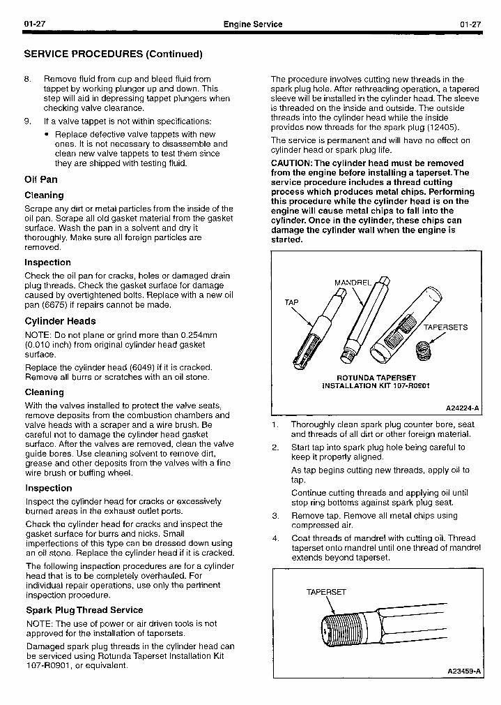
01-27 Engine Service 01-27
SERVICE PROCEDURES (Continued)
8. Remove fluid from cup and bleed fluid from tappet by working plunger up and down. This step will aid in depressing tappet plungers when checking valve clearance.
9. If a valve tappet is not within specifications:
l Replace defective valve tappets with new ones. It is not necessary to disassemble and clean new valve tappets to test them since they are shipped with testing fluid.
Oil Pan
Cleaning
Scrape any dirt or metal particles from the inside of the oil pan. Scrape all old gasket material from the gasket surface. Wash the pan in a solvent and dry it thoroughly. Make sure all foreign particles are removed.
Inspection
Check the oil pan for cracks, holes or damaged drain plug threads. Check the gasket surface for damage caused by over-tightened bolts. Replace with a new oil pan (6675) if repairs cannot be made.
Cylinder Heads NOTE: Do not plane or grind more than 0.254mm (0.010 inch) from original cylinder head gasket surface.
Replace the cylinder head (6049) if it is cracked. Remove all burrs or scratches with an oil stone.
Cleaning
With the valves installed to protect the valve seats, remove deposits from the combustion chambers and valve heads with a scraper and a wire brush. Be careful not to damage the cylinder head gasket surface. After the valves are removed, clean the valve guide bores. Use cleaning solvent to remove dirt, grease and other deposits from the valves with a fine wire brush or buffing wheel.
Inspection
Inspect the cylinder head for cracks or excessively burned areas in the exhaust outlet ports.
Check the cylinder head for cracks and inspect the gasket surface for burrs and nicks. Small imperfections of this type can be dressed down using an oil stone. Replace the cylinder head if it is cracked.
The following inspection procedures are for a cylinder head that is to be completely overhauled. For individual repair operations, use only the pertinent inspection procedure.
Spark Plug Thread Service
NOTE: The use of power or air driven tools is not approved for the installation of tapersets.
Damaged spark plug threads in the cylinder head can be serviced using Rotunda Taperset Installation Kit 107-R0901, or equivalent.
The procedure involves cutting new threads in the spark plug hole. After rethreading operation, a tapered sleeve will be installed in the cylinder head. The sleeve is threaded on the inside and outside. The outside threads into the cylinder head while the inside provides new threads for the spark plug (12405).
The service is permanent and will have no effect on cylinder head or spark plug life.
CAUTION:The cylinder head must be removed from the engine before installing a taperset.The service procedure includes a thread cutting process which produces metal chips. Performing this procedure while the cylinder head is on the engine will cause metal chips to fall into the cylinder. Once in the cylinder, these chips can damage the cylinder wall when the engine is started.
SETS
ROTUNDA TAPERSET INSTALLATION KIT 107-R0901
A24224-A
I. Thoroughly clean spark plug counter bore, seat and threads of all dirt or other foreign material.
2. Start tap into spark plug hole being careful to keep it properly aligned.
As tap begins cutting new threads, apply oil to tap.
Continue cutting threads and applying oil until stop ring bottoms against spark plug seat.
3. Remove tap. Remove all metal chips using compressed air.
4. Coat threads of mandrel with cutting oil. Thread taperset onto mandrel until one thread of mandrel extends beyond taperset.
TAPERSET
A23459-A
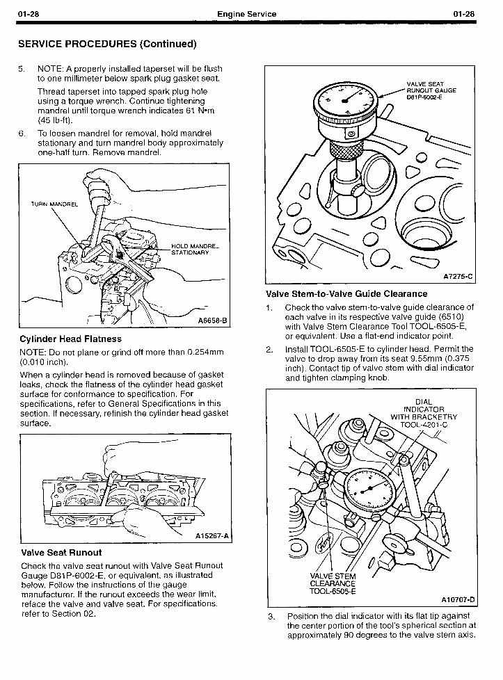
01-28 Enaine Service 01-28
SERVICE PROCEDURES (Continued)
5. NOTE: A properly installed taperset will be flush to one millimeter below spark plug gasket seat.
Thread taperset into tapped spark plug hole using a torque wrench. Continue tightening mandrel until torque wrench indicates 61 Nom (45 lb-ft).
;. To loosen mandrel for removal, hold mandrel stationary and turn mandrel body approximately one-half turn. Remove mandrel.
TURN MANDREL 1\
\ j,
HOLD MANDREL STATIONARY
Cylinder Head Flatness
NOTE: Do not plane or grind off more than 0.254mm (0.010 inch).
When a cylinder head is removed because of gasket leaks, check the flatness of the cylinder head gasket surface for conformance to specification. For specifications, refer to General Specifications in this section. If necessary, refinish the cylinder head gasket surface.
k 1 Al5267-A
Valve Seat Runout
Check the valve seat runout with Valve Seat Runout Gauge D81 P-6002-E, or equivalent, as illustrated below. Follow the instructions of the gauge manufacturer. If the runout exceeds the wear limit, reface the valve and valve seat. For specifications, refer to Section 02.
VALVE SEAT RUNOUT GAUGE 08 1 P-6002-E
A72754
Valve Stem-to-Valve Guide Clearance
1. Check the valve stem-to-valve guide clearance of each valve in its respective valve guide (6510) with Valve Stem Clearance Tool TOOL-6505-E, or equivalent. Use a flat-end indicator point.
2. Install TOOL-6505-E to cylinder head. Permit the valve to drop away from its seat 9.55mm (0.375 inch). Contact tip of valve stem with dial indicator and tighten clamping knob.
DIAL INDICATOR
VALVE STh/l CLFAFWNCE TOOL-6505-E
Al 0707-D
3. Position the dial indicator with its flat tip against the center portion of the tool’s spherical section at approximately 90 degrees to the valve stem axis.
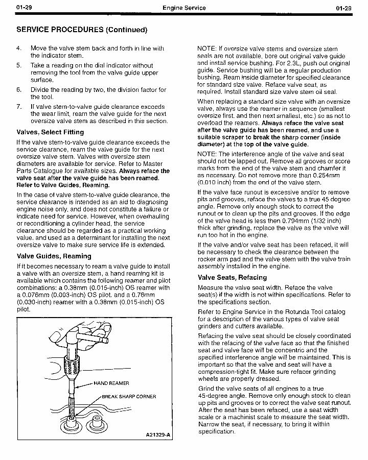
01-29 Engine Service 01-29
SERVICE PROCEDURES (Continued)
4. Move the valve stem back and forth in line with the indicator stem.
5. Take a reading on the dial indicator without removing the tool from the valve guide upper surface.
6. Divide the reading by two, the division factor for the tool.
7. If valve stem-to-valve guide clearance exceeds the wear limit, ream the valve guide for the next oversize valve stem as described in this section.
Valves, Select Fitting
If the valve stem-to-valve guide clearance exceeds the service clearance, ream the valve guide for the next oversize valve stem. Valves with oversize stem diameters are available for service. Refer to Master Parts Catalogue for available sizes. Always reface the valve seat after the valve guide has been reamed. Refer to Valve Guides, Reaming.
In the case of valve stem-to-valve guide clearance, the service clearance is intended as an aid to diagnosing engine noise only, and does not constitute a failure or indicate need for service. However, when overhauling or reconditioning a cylinder head, the service clearance should be regarded as a practical working value, and used as a determinant for installing the next oversize valve to make sure service life is extended.
Valve Guides, Reaming
If it becomes necessary to ream a valve guide to install a valve with an oversize stem, a hand reaming kit is available which contains the following reamer and pilot combinations: a 0.38mm (0.015-inch) OS reamer with a 0.076mm (0.003-inch) OS pilot, and a 0.76mm (0.030-inch) reamer with a 0.38mm (0.015-inch) OS pilot.
HAND REAMER
BREAK SHARP CORNER
A21 329-A
NOTE: If oversize valve stems and oversize stem seals are not available, bore out original valve guide and install service bushing. For 23L, push out original guide. Service bushing will be a regular production bushing. Ream inside diameter for specified clearance for standard size valve. Reface valve seat, as required. Install standard size valve stem oil seal.
When replacing a standard size valve with an oversize valve, always use the reamer in sequence (smallest oversize first, and then next smallest, etc.) so as not to overload the reamers. Always reface the valve seat after the valve guide has been reamed, and use a suitable scraper to break the sharp corner (inside diameter) at the top of the valve guide.
NOTE: The interference angle of the valve and seat should not be lapped out. Remove all grooves or score marks from the end of the valve stem and chamfer it as necessary. Do not remove more than 0.254mm (0.010 inch) from the end of the valve stem.
If the valve face runout is excessive and/or to remove pits and grooves, reface the valves to a true 45 degree angle. Remove only enough stock to correct the runout or to clean up the pits and grooves. If the edge of the valve head is less then 0.794mm (l/32 inch) thick after grinding, replace the valve as the valve will run too hot in the engine.
If the valve and/or valve seat has been refaced, it will be necessary to check the clearance between the rocker arm pad and the valve stem with the valve train assembly installed in the engine.
Valve Seats, Refacing
Measure the valve seat width. Reface the valve seat(s) if the width is not within specifications. Refer to the specifications section.
Refer to Engine Service in the Rotunda Tool catalog for a description of the various types of valve seat grinders and cutters available.
Refacing the valve seat should be closely coordinated with the refacing of the valve face so that the finished seat and valve face will be concentric and the specified interference angle will be maintained. This is important so that the valve and seat will have a compression-tight fit. Make sure refacer grinding wheels are properly dressed.
Grind the valve seats of all engines to a true 45-degree angle. Remove only enough stock to clean up pits and grooves or to correct the valve seat runout. After the seat has been refaced, use a seat width scale or a machinist scale to measure the seat width. Narrow the seat, if necessary, to bring it within specification.
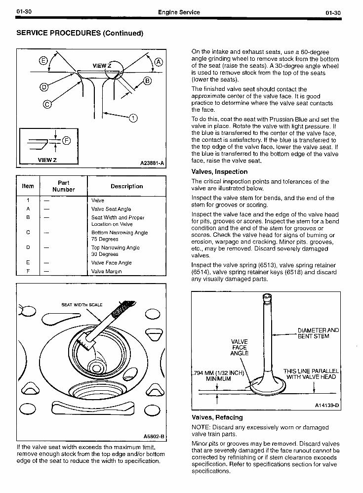
01-30 Engine Service 01-30
SERVICE PROCEDURES (Continued)
A23881 -A
Item Part
Number Description
1 - Valve
A - Valve Seat Angle
B - Seat Width and Proper Location on Valve
c - Bottom Narrowing Angle 75 Degrees
D - Top Narrowing Angle 30 Degrees
E - Valve Face Angle
F - Valve Margin
A6802-B
If the valve seat width exceeds the maximum limit, remove enough stock from the top edge and/or bottom edge of the seat to reduce the width to specification.
On the intake and exhaust seats, use a 6O-degree angle grinding wheel to remove stock from the bottom of the seat (raise the seats). A 30-degree angle wheel is used to remove stock from the top of the seats (lower the seats).
The finished valve seat should contact the approximate center of the valve face. It is good practice to determine where the valve seat contacts the face.
To do this, coat the seat with Prussian Blue and set the valve in place. Rotate the valve with light pressure. If the blue is transferred to the center of the valve face, the contact is satisfactory. If the blue is transferred to the top edge of the valve face, lower the valve seat. If the blue is transferred to the bottom edge of the valve face, raise the valve seat.
Valves, Inspection
The critical inspection points and tolerances of the valve are illustrated below.
Inspect the valve stem for bends, and the end of the stem for grooves or scoring.
Inspect the valve face and the edge of the valve head for pits, grooves or scores. Inspect the stem for a bend condition and the end of the stem for grooves or scores. Check the valve head for signs of burning or erosion, warpage and cracking. Minor pits, grooves, etc., may be removed. Discard severely damaged valves.
Inspect the valve spring (6513), valve spring retainer (6514), valve spring retainer keys (6518) and discard any visually damaged parts.
DIAMETER AN D I BENT STEM
VALVE FACE
ANGLE
,794 MM (l/32 INCH) THIS LINE PARALLEL WITH VALVE HEAD
1 I Al 4139-D /
Valves, Refacing
NOTE: Discard any excessively worn or damaged valve train parts.
Minor pits or grooves may be removed. Discard valves that are severely damaged if the face runout cannot be corrected by refinishing or if stem clearance exceeds specification. Refer to specifications section for valve specifications.
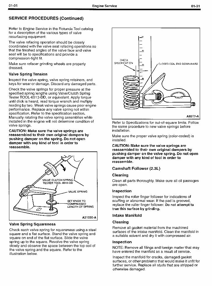
01-31 Engine Service
SERVICE PROCEDURES (Continued)
Refer to Engine Service in the Rotunda Tool catalog for a description of the various types of valve resurfacing equipment.
The valve refacing operation should be closely coordinated with the valve seat refacing operations so that the finished angles of the valve face and valve seat will be to specifications and provide a compression-tight fit.
Make sure refacer grinding wheels are properly dressed.
Valve Spring Tension
Inspect the valve spring, valve spring retainers, and keys for wear or damage. Discard any damaged parts.
Check the valve springs for proper pressure at the specified spring lengths using Valve/Clutch Spring Tester TOOL-651 3-DD, or equivalent. Apply torque until click is heard, read torque wrench and multiply reading by two. Weak valve springs cause poor engine performance. Replace any valve spring not within specification. Refer to the specification section. Manually rotating the valve spring assemblies while installed in the engine will not determine condition of valve springs.
CAUTION: Make sure the valve springs are reassembled to their own original dampers by pushing damper on the spring. Do not open damper with any kind of tool in order to reassemble.
VALVE SPRING
SET KNOB TO COMPRESSED LENGTH OF SPRING
A21 330-A
Valve Spring Squareness
Check each valve spring for squareness using a steel square and a flat surface. Stand the valve spring and square on end of the flat surface. Slide the valve spring up to the square. Revolve the valve spring slowly and observe the space between the top coil of the valve spring and the square. Refer to the illustration below.
I-- I - - I I - h) - I- I -
CHECK
CLOSED COIL END DOWNWARD
A851 7-A
Refer to Specifications for out-of-square limits. Follow the same procedure to new valve springs before installation.
Make sure the proper valve spring (color-coded) is installed.
CAUTION: Make sure the valve springs are reassembled to their own original dampers by pushing damper on the valve spring. Do not open damper with any kind of tool in order to reassemble.
Camshaft Follower (2.3L)
Cleaning
Clean all parts thoroughly. Make sure all oil passages are open.
Inspection
Inspect the roller finger follower for indications of scuffing or abnormal wear. If the pad is grooved, replace the roller finger follower. Do not attempt to true this surface by grinding.
Intake Manifold
Cleaning
Remove all gasket material from the machined surfaces of the intake manifold. Clean the manifold in a suitable solvent and dry it with compressed air.
Inspection
NOTE: Remove all filings and foreign matter that may have entered the manifold as a result of service.
Inspect the manifold for cracks, damaged gasket surfaces, or other problems that would make it unfit for further service. Replace all studs that are stripped or otherwise damaged.
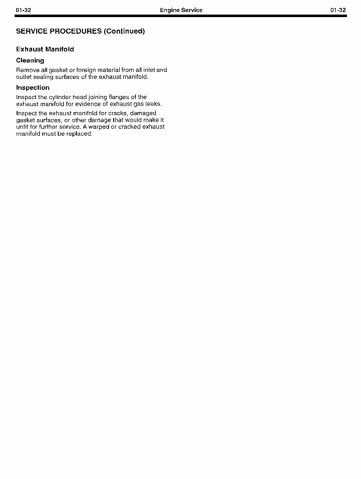
01-32 Engine Service 01-32
SERVICE PROCEDURES (Continued)
Exhaust Manifold
Cleaning
Remove all gasket or foreign material from all inlet and outlet sealing surfaces of the exhaust manifold.
Inspection
Inspect the cylinder head joining flanges of the exhaust manifold for evidence of exhaust gas leaks.
Inspect the exhaust manifold for cracks, damaged gasket surfaces, or other damage that would make it unfit for further service. A warped or cracked exhaust manifold must be replaced.
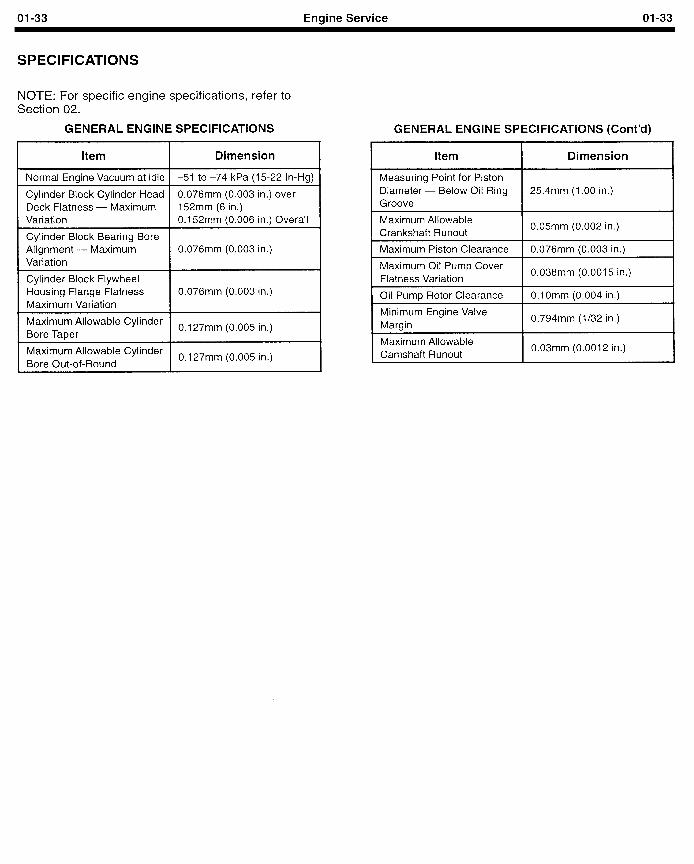
01-33 Engine Service 01-33
SPECIFICATIONS
NOTE: For specific engine specifications, refer to Section 02.
GENERAL ENGINE SPECIFICATIONS
Item Dimension
1 Normal Engine Vacuum at Idle 1 -51 to -74 kPa (15-22 In-Hg)
Cylinder Block Cylinder Head 0.076mm (0.003 in.) over Deck Flatness - Maximum 152mm (6 in.) Variation 0.152mm (0.006 in.) Overall
Cylinder Block Bearing Bore Alignment - Maximum 0.076mm (0.003 in.) Variation
EFEzs / 0.076mm (0.003 in.)
Maximum Allowable Cylinder Bore Taper
0.127mm (0.005 in.)
Maximum Allowable Cylinder Bore Out-of-Round
0.127mm (0.005 in.)
GENERAL ENGINE SPECIFICATIONS (Cont’d)
Item Dimension
Measuring Point for Piston Diameter - Below Oil Ring Groove
25.4mm (1 .OO in.)
I Maximum Allowable Crankshaft Runout I 0.05mm (0.002 in.)
1 Maximum Piston Clearance 1 0.076mm (0.003 in.) I
I Maximum Oil Pump Cover Flatness Variation I 0.038mm (0.0015 in.)
1 Oil Pump Rotor Clearance I O.lOmm (0.004 in.) I
I 0.794mm (l/32 in.)
Maximum Allowable Camshaft Runout
0.03mm (0.0012 in.)
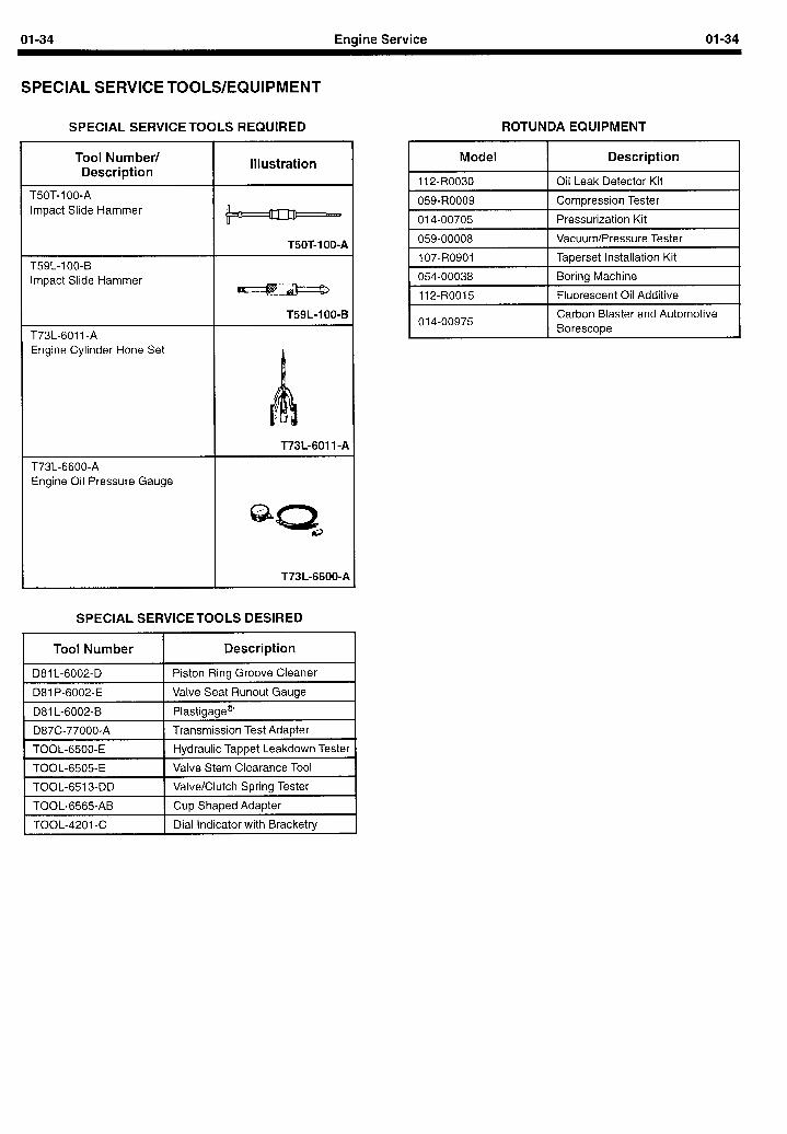
01-34 Engine Service 01-34
SPECIAL SERVICE TOOLS/EQUIPMENT
SPECIAL SERVICE TOOLS REQUIRED
Tool Number/ Description
Illustration
T50T-100-A Impact Slide Hammer
T59L-100-B Impact Slide Hammer
T73L-6011 -A Engine Cylinder Hone Set
T50T-100-A
m
T59L-100-B
T73L-6600-A Engine Oil Pressure Gauge
T73L-6011-A
@c2 ?e
T73L-6600-A
SPECIAL SERVICETOOLS DESIRED
I Tool Number I Description I
1 D81 L-6002-D 1 Piston Ring Groove Cleaner
1 D81 P-6002-E I Valve Seat Runout Gauge
1 D81 L-6002-B 1 Plastigage@
1 D87C-77000-A I Transmission Test Adapter
1 TOOL-6500-E 1 Hydraulic Tappet Leakdown Tester I
1 TOOL-6505-E 1 Valve Stem Clearance Tool
1 TOOL-651 3-DD I Valve/Clutch Spring Tester
ROTUNDA EQUIPMENT
Model Description
1 112-R0030 I Oil Leak Detector Kit
1 059-R0009 I Compression Tester
I 014-00705 I Pressurization Kit I 1 059-00008 I Vacuum/Pressure Tester
1 107-R0901 I Taperset Installation Kit
1 054-00038 I Boring Machine
1 112-R0015 I Fluorescent Oil Additive
014-00975 Carbon Blaster and Automotive Borescope
1 TOOL-6565-AB I Cup Shaped Adapter
1 TOOL-4201-C I Dial Indicator with Bracketry
02-I Engine Service, 2.3L 02-I
SECTION TITLE PAGE SECTION TITLE PAGE
ENGINE SERVICE ‘*..,.**.~...~..,~~.‘..*,**.,~....~...*.‘~....~,,,....*....~.*....*‘, 01-I AUXILIARY SYSTEMS *=............~~~~,*~.~*.‘*...~*‘*~~~...*..**~*~‘,..,,**.~.... 03-l ENGINE SERVICE, 2.3L . . . . . . . . . . . . . . . . . . . . . . . . . . . . . . . . . . . . . . . . . . . . . . . . . . . . . . . . . . . . 02-l
SECTION 02 - 2.3L Engine
SUBJECT PAGE SUBJECT PAGE DESCRIPTION AND OPERATION
Engine ......................................... ...3 Engine Identification ................................ .3 Engine Code Information ............................ .4 Crankshaft ...................................... ...4 Camshaft ....................................... ...4 Valve Train ........................................ .4 Positive Crankcase Ventilation System ................ 5 Lubrication System. ................................. .
OilPan ......................................... ...5 Engine Lubrication System ........................... . OilPump .......................................... . Engine Cooling System ............................. .8 Drive Belt System .................................. .8 Ignition System .................................... .8 Fuel System. ...................................... .8 Engine Governing System ........................... .8 Mechanical Governor ............................... .8 Electronic Governor ................................ .8 Fail-safe ........................................ ...8 Velocity Governor .................................. .8
2.3L ENGINE SERVICE Valve Cover and Gasket ............................ .I3
Removal ................... .....................l 3 Installation ..................................... .I 3
Camshaft Follower and Hydraulic Lash Adjuster ....... .I3 Removal ...................................... ..I 3 Installation ..................................... .I 4
Valve Spring, Retainer and Valve Stem Seal. ........... .I4 Removal ...................................... ..I 4 Installation ..................................... .14
Crankshaft Pulley and Damper ...................... .15 Removal ...................................... ..I 5 Installation ..................................... .I 5
Camshaft Timing Belt Outer Cover ................... .I6 Installation.. ................................. -16
Camshaft Timing Belt Inner Cover ................... .I7 Removal ........................................ 17
Installation ...................................... 17
CamshaftTiming Belt .............................. .I8 Removal ...................................... ..I 8 Installation ..................................... .20
Camshaft and Oil Pump Sprocket .................... .21 Removal ...................................... ..2 I Installation ..................................... .22
Crankshaft Sprocket ............................... .22 Removal ...................................... ..2 2 Installation ..................................... .22
2.3L ENGINE SERVICE (Cont’d.) Timing BeltTensioner ............................. .22
Removal........................................2 2 Installation ..................................... .22
Camshaft.........................................2 3 Removal........................................2 3 Installation ..................................... .25
Camshaft and Oil Pump Oil Seal .................... .25 Removal........................................2 5 Installation ..................................... .26
Cylinder Block Front Cover Seal .................... .26 Removal........................................2 6 Installation ..................................... .26
CylinderHead.....................................2 6 Removal........................................2 6 Installation ..................................... .27
Water Pump ..................................... .30 Removal........................................3 0 Installation ...................................... 32
Water Thermostat and Outlet Connection ............. .32 Removal........................................3 2 Installation ...................................... 33
Intake Manifold ................................... .33 Removal......................................~.3 3 Installation ...................................... 34
Carburetor ....................................... .35 Removal...................................~....3 5 Installation ..................................... .36
Exhaust Manifold ................................. .37 Removal........................................3 7 Installation ..................................... .37
OilPump.........................................3 8 Removal........................................3 8 Installation ..................................... .38
Crankshaft Rear Oil Seal ........................... .39 Removal.~......................................3 9 Installation ...................................... 39
Oil Filter and Adapter .............................. .40 Removal........................................4 0 Installation ..................................... .40
Sensors..........................................4 0 Oil Pressure Sender ............................. .40 Removal and Installation ......................... -40
Engine Front Cover ............................... .40 Removal........................................4 1 Installation ..................................... .42
02-2 Engine Service, 2.3L 02-2
SECTION 02 - 2.3L Engine
SUBJECT PAGE SUBJECT 2.3L ENGINE SERVICE (Cont’d.)
Oil Pan ........................................... 44 Removal........................................4 4 Installation ...................................... 44
Oil Pump Screen, Cover, andTube .................... 45 Removal........................................4 5 Installation ..................................... .45
Crankshaft........................................4 6 Removal ........................................ 46 Installation ...................................... 47
Crankshaft Main Bearings .......................... .49 Removal ........................................ 49 Installation ..................................... .50
Pistons and Connecting Rods ...................... .51 Removal ........................................ 51 Installation ..................................... .52
Connecting Rod Bearings ........................... 53 Removal........................................5 3 Installation ...................................... 53
DISASSEMBLY AND ASSEMBLY Subassemblies .................................... 55 Cylinder Head ..................................... 55
Disassembly. .................................... 55 Assembly ....................................... 57
DISASSEMBLY AND ASSEMBLY (Cont’d.) Piston and Piston Pins ............................. 60
Disassembly .................................... 60 Assembly.......................................6 0
Cylinder Block Assembly ........................... 60 Disassembly .................................... 60 Assembly ....................................... 60
Hydraulic Lash Adjuster ............................ 61 Disassembly and Assembly ........................ 61
Cylinder Block, Bare ............................... 61 Disassembly .................................... 61 Assembly ....................................... 61
Adjustments ...................................... 61 Valve Clearance, Hydraulic Valve Lash Adjuster ........ 61 Camshaft Timing .................................. 62 Checking Timing .................................. 62 Adjusting Timing Belt .............................. 64
SPECIFICATIONS .................................... 68 Engine Operating Speeds - LRG 423 ................. 71
SPECIAL SERVICE TOOLS/EQUIPMENT. ................. 72
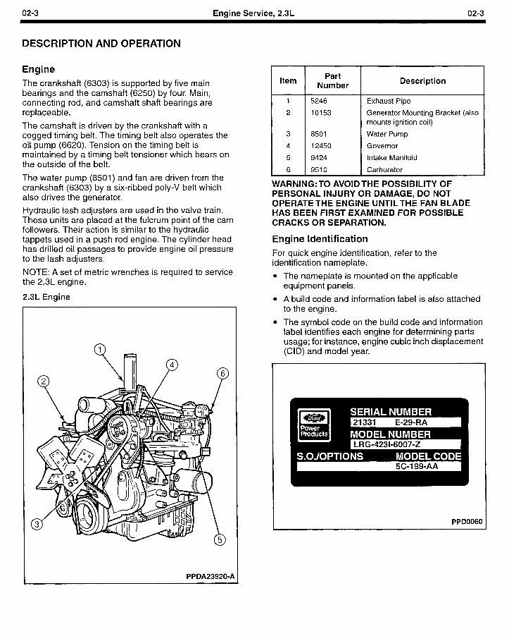
02-3 Enqine Service, 2.3L 02-3
DESCRIPTION AND OPERATION
Engine The crankshaft (6303) is supported by five main bearings and the camshaft (6250) by four. Main, connecting rod, and camshaft shaft bearings are replaceable.
The camshaft is driven by the crankshaft with a cogged timing belt. The timing belt also operates the oil pump (6620). Tension on the timing belt is maintained by a timing belt tensioner which bears on the outside of the belt.
The water pump (8501) and fan are driven from the crankshaft (6303) by a six-ribbed poly-V belt which also drives the generator.
Hydraulic lash adjusters are used in the valve train. These units are placed at the fulcrum point of the cam followers. Their action is similar to the hydraulic tappets used in a push rod engine. The cylinder head has drilled oil passages to provide engine oil pressure to the lash adjusters.
NOTE: A set of metric wrenches is required to service the 2.3L engine.
2.3L Engine
PPDA23920-A
Item Part
Number Description
5246
10153
8501
12450
9424
Exhaust Pipe
Generator Mounting Bracket (also mounts ignition coil)
Water Pump
Governor
Intake Manifold
1 9510 Carburetor
WARNING: TO AVOID THE POSSIBILITY OF PERSONAL INJURY OR DAMAGE, DO NOT OPERATETHE ENGINE UNTILTHE FAN BLADE HAS BEEN FIRST EXAMINED FOR POSSIBLE CRACKS OR SEPARATION.
Engine Identification For quick engine identification, refer to the identification nameplate.
l The nameplate is mounted on the applicable equipment panels.
l A build code and information label is also attached to the engine.
l The symbol code on the build code and information label identifies each engine for determining parts usage; for instance, engine cubic inch displacement (CID) and model year.
PPD0060
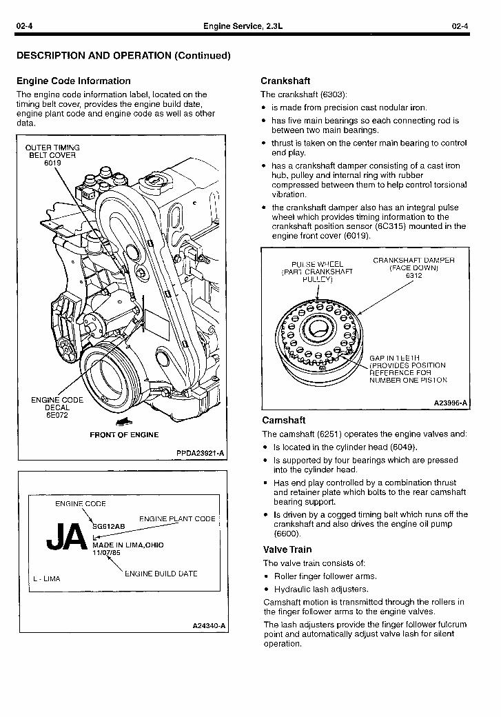
02-4 Engine Service, 2.3L 02-4
DESCRIPTION AND OPERATION (Continued)
Engine Code Information The engine code information label, located on the timing belt cover, provides the engine build date, engine plant code and engine code as well as other data.
OUTER TIMING BELT COVER
6019
FRONT OF ENGINE
PPDA23921 -P
ENGINE CODE
\ ENGINE PLANT CODE
MADE IN LIMA,OtiIO
L - LIMA ENGINE BUILD DATE
A24340-A
Crankshaft The crankshaft (6303):
l is made from precision cast nodular iron.
l has five main bearings so each connecting rod is between two main bearings.
l thrust is taken on the center main bearing to control end play.
l has a crankshaft damper consisting of a cast iron hub, pulley and internal ring with rubber compressed between them to help control torsional vibration.
l the crankshaft damper also has an integral pulse wheel which provides timing information to the crankshaft position sensor (6C315) mounted in the engine front cover (6019).
PULSE WHEEL (PART CRANKSHAFT
PULLEY)
CRANKSHAFT DAMPER (FACE DOWN)
6312 /
GAP IN TEETH (PROVIDES POSITION REFERENCE FOR NUMBER ONE PISTON
A239960A
Camshaft The camshaft (6251) operates the engine valves and:
l Is located in the cylinder head (6049).
l Is supported by four bearings which are pressed into the cylinder head.
l Has end play controlled by a combination thrust and retainer plate which bolts to the rear camshaft bearing support.
l Is driven by a cogged timing belt which runs off the crankshaft and also drives the engine oil pump (6600).
Valve Train The valve train consists of:
l Roller finger follower arms.
l Hydraulic lash adjusters.
Camshaft motion is transmitted through the rollers in the finger follower arms to the engine valves.
The lash adjusters provide the finger follower fulcrum point and automatically adjust valve lash for silent operation.
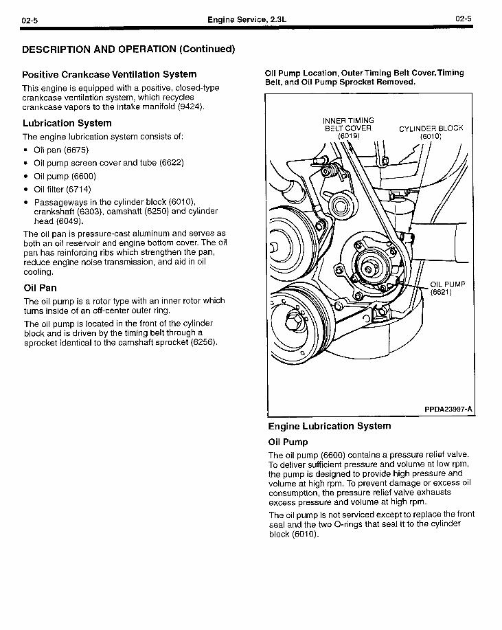
02-5 Engine Service, 2.3L 02-5
DESCRIPTION AND OPERATION (Continued)
Positive Crankcase Ventilation System This engine is equipped with a positive, closed-type crankcase ventilation system, which recycles crankcase vapors to the intake manifold (9424).
Lubrication System The engine lubrication system consists of
l Oil pan (6675)
l Oil pump screen cover and tube (6622
l Oil pump (6600)
l Oil filter (6714)
l Passageways in the cylinder block (6010), crankshaft (6303), camshaft (6250) and cylinder head (6049).
The oil pan is pressure-cast aluminum and serves as both an oil reservoir and engine bottom cover. The oil pan has reinforcing ribs which strengthen the pan, reduce engine noise transmission, and aid in oil cooling.
Oil Pan The oil pump is a rotor type with an inner rotor which turns inside of an off-center outer ring.
The oil pump is located in the front of the cylinder block and is driven by the timing belt through a sprocket identical to the camshaft sprocket (6256).
Oil Pump Location, Outer Timing Belt Cover, Timing Belt, and Oil Pump Sprocket Removed.
INNER TIMING BELT COVER CYLINDER BLOCK
(6019) (6010)
PPDA23997-A
Engine Lubrication System
Oil Pump
The oil pump (6600) contains a pressure relief valve. To deliver sufficient pressure and volume at low rpm, the pump is designed to provide high pressure and volume at high rpm. To prevent damage or excess oil consumption, the pressure relief valve exhausts excess pressure and volume at high rpm.
The oil pump is not serviced except to replace the front seal and the two O-rings that seal it to the cylinder block (6010).
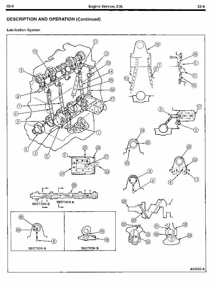
02-6 Engine Service, 2.3L 02-6
DESCRIPTION AND OPERATION (Continued)
Lubrication System
4 w fT?-
. SECTION B
SECTION A
L-
SECTION A
0 35
A239234
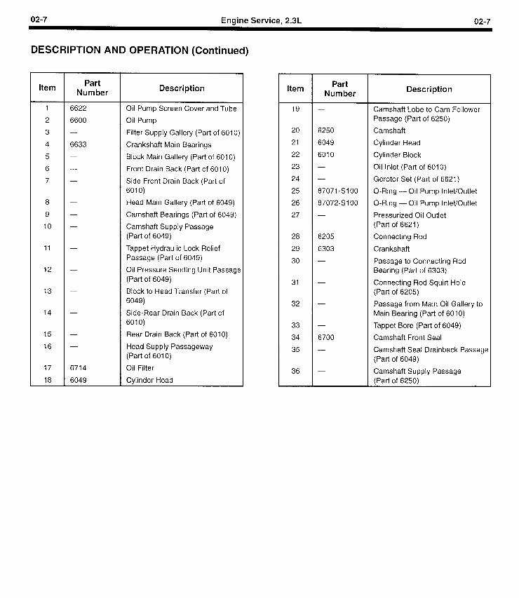
02-7 Engine Service, 2.3L 02-7
DESCRIPTION AND OPERATION (Continued)
Item Part
Number Description
1 6622 Oil Pump Screen Cover and Tube
2 6600 Oil Pump
3 - Filter Supply Gallery (Part of 6010)
4 6633 Crankshaft Main Bearings
5 - Block Main Gallery (Part of 6010)
6 - Front Drain Back (Part of 6010)
7 - Side Front Drain Back (Part of 6010)
8 - Head Main Gallery (Part of 6049)
9 - Camshaft Bearings (Part of 6049)
IO - Camshaft Supply Passage (Part of 6049)
11 - Tappet Hydraulic Lock Relief Passage (Part of 6049)
12 - Oil Pressure Sending Unit Passage (Part of 6049)
13 - Block to Head Transfer (Part of 6049)
14 - Side-Rear Drain Back (Part of 6010)
15 - Rear Drain Back (Part of 6010)
16 - Head Supply Passageway (Part of 6010)
17 6714 Oil Filter
18 6049 Cylinder Head
Item Part Number
19 -
20 6250
21 6049
22 6010
23 -
24 -
25 87071 -SlOO
26 87072-SIOO
27 -
28 6205
29 6303
30 -
31 -
32 -
33 -
34 6700
35 -
36 -
Description
Camshaft Lobe to Cam Follower Passage (Part of 6250)
Camshaft
Cylinder Head
Cylinder Block
Oil Inlet (Part of 6010)
Gerotor Set (Part of 6621)
O-Ring - Oil Pump Inlet/Outlet
O-Ring - Oil Pump Inlet/Outlet
Pressurized Oil Outlet (Part of 6621)
Connecting Rod
Crankshaft
Passage to Connecting Rod Bearing (Part of 6303)
Connecting Rod Squirt Hole (Part of 6205)
Passage from Main Oil Gallery to Main Bearing (Part of 6010)
Tappet Bore (Part of 6049)
Camshaft Front Seal
Camshaft Seal Drainback Passage (Part of 6049)
Camshaft Supply Passage (Part of 6250)
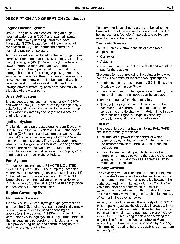
02-8 Engine Service, 2.3L 02-8
DESCRIPTION AND OPERATION (Continued)
Engine Cooling System The 23L engine is liquid cooled using an engine mounted water pump (8501) and external radiator. This is a full flow system regulated by a water thermostat (8575) located behind the water outlet connection (8595). The thermostat controls and maintains engine temperature.
Typical coolant flow produced by the centrifugal water pump is through the engine block (6010) and then into the cylinder head (6049). From the cylinder head it flows through the thermostat and water outlet connection into the upper radiator hose and down through the radiator for cooling. A passage from the water outlet connection through a heater/by-pass hose allows coolant to flow to the intake manifold which provides heat for fuel atomization. It then flows through another heater/by-pass hose assembly to the inlet side of the water pump.
Drive Belt System Engine accessories, such as the generator (10300) and water pump (8501), are driven by a single poly-V belt. A direct drive fan is attached to the water pump pulley which is driven by the poly-V belt when the engine is running.
Ignition System The ignition used on the 2.3L engine is an Electronic Distributorless Ignition System (EDIS). A crankshaft position (CKP) sensor and vacuum port on the intake manifold ( provide the necessary information to an ignition module (12A297). The module determines when to fire the ignition coil mounted on the generator bracket, based on the two sensors. Standard distributorless ignition coil, wires and spark plugs are used to ignite the fuel in the cylinders.
Fuel System The fuel system includes a REMOTE-MOUNTED electric fuel pump (9350). The pump regulates and maintains fuel flow, through an in-line fuel filter (9155) to the carburetor mounted on the intake manifold. Depending on engine application, either a Holley or Zenith model carburetor (9510) can be used to provide the necessary fuel for combustion.
Engine Governing System
Mechanical Governor
Mechanical, belt driven, flyweight type governors are used on the 2.3L engine. Constant speed and variable speed governors can be used depending on application. The governor (12450) is attached to the carburetor by a linkage system. The governor, through the linkage, limits carburetor throttle plate opening. This provides regulation and control of engine rpm during operating engine loads.
The governor is attached to a bracket bolted to the lower left front of the engine block and is slotted for belt adjustment. A single V-type belt and pulley are used to operate the governor.
Electronic Governor
The electronic governor consists of three main components:
l Controller
l Actuator
l Carburetor with special throttle shaft and mounting pad for the actuator
The controller is connected to the actuator by a wire harness. The controller receives two input signals:
l Engine speed is sensed from the EDIS (Electronic Distributorless Ignition System)
l Using a remote-mounted speed select switch, up to four engine operating speeds can be selected.
There is one output from the controller:
l The controller sends a modulated signal to the actuator at the carburetor. The actuator in turn controls the throttle shaft, which determines throttle plate position. Signal strength is varied, by the controller, depending on the input values.
Fail-safe
The electronic governor has an internal FAIL-SAFE circuit that instantly reacts to:
l Interruption of power to the controller which removes power to the actuator. A return spring in the actuator moves the throttle shaft to minimum fuel position.
l Loss of speed signal input which causes the controller to remove power to the actuator. A return spring in the actuator moves the throttle shaft to minimum fuel position.
Velocity Governor
The velocity governor is an engine speed limiting type, and operates by metering the air/fuel mixture flow from the carburetor. The governor is installed between the carburetor and the intake manifold. It contains a disc valve mounted on a shaft which is similar in appearance to a carburetor butterfly valve. However, unlike a butterfly valve, the governor shaft is mounted off center in the governor bore.
As engine speed increases, the velocity of the air/fuel mixture passing across the disc valve increases. Since the governor shaft is mounted off center, the force of the flowing air/fuel mixture attempts to close the disc valve, therefore restricting the flow and slowing the engine. The force of the flowing air/fuel mixture attempting to close the valve is opposed by a spring. The force of the spring therefore establishes maximum engine speed.
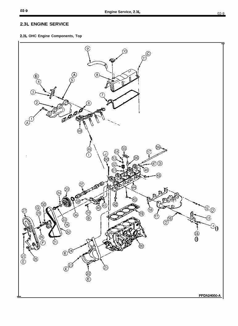
02-9 Engine Service, 2.3L 02-9
2.3L ENGINE SERVICE
2.3L OHC Engine Components, Top
0B
015
0B
PPDA24000-A
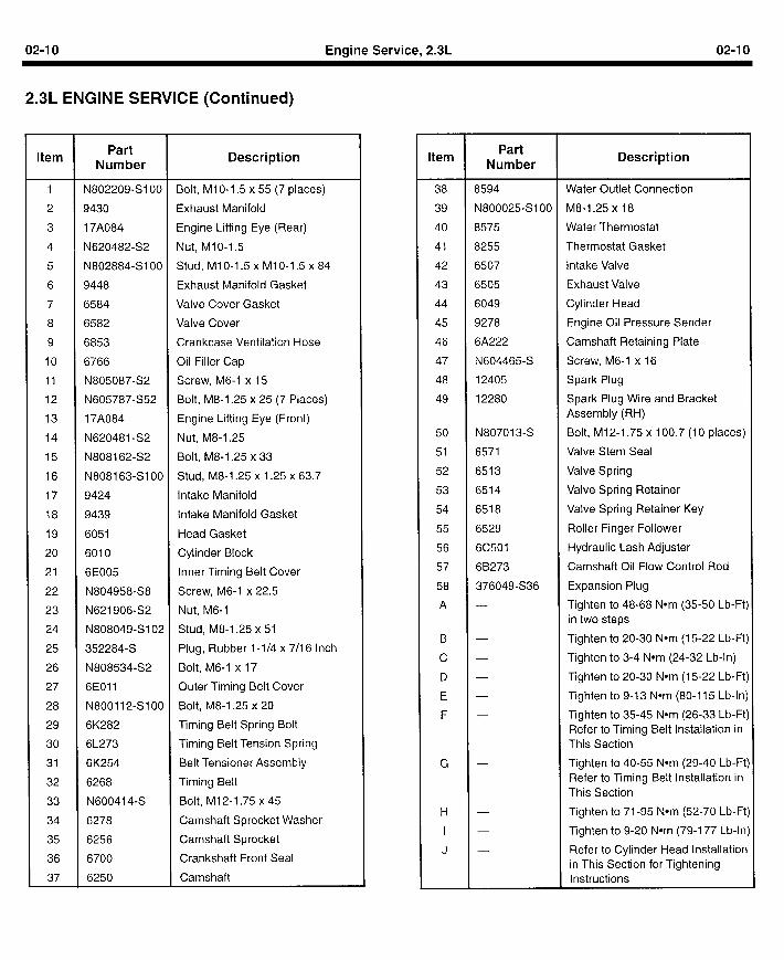
02-I 0 Engine Service, 2.3L 02-I 0
2.3L ENGINE SERVICE (Continued)
Item Part Number
Description
1 N802209-SIOO Bolt, MIO-1.5 x 55 (7 places)
2 9430 Exhaust Manifold
3 17A084 Engine Lifting Eye (Rear)
4 N620482-S2 Nut, Ml O-l 5
5 N802884-SIOO Stud, MlO-1.5 x MlO-1.5 x 84
6 9448 Exhaust Manifold Gasket
7 6584 Valve Cover Gasket
8 6582 Valve Cover
9 6853 Crankcase Ventilation Hose
10 6766 Oil Filler Cap
11 N805087-S2 Screw, M6-1 x 15
12 N605787-S52 Bolt, M8-1.25 x 25 (7 Places)
13 17A084 Engine Lifting Eye (Front)
14 N620481 -S2 Nut, M8-1.25
15 N808162S2 Bolt, M8-1.25 x 33
16 N808163-SIOO Stud, M8-1.25 x 1.25 x 63.7
17 9424 Intake Manifold
18 9439 Intake Manifold Gasket
19 6051 Head Gasket
20 6010 Cylinder Block
21 6E005 Inner Timing Belt Cover
22 N804958-S8 Screw, M6-1 x 22.5
23 N621906-S2 Nut, M6-1
24 N808049S102 Stud, M8-1.25 x 51
25 352284-S Plug, Rubber l-1/4 x 7/l 6 Inch
26 N808534S2 Bolt, M6-1 x 17
27 6EOll Outer Timing Belt Cover
28 N800112-Sl OO Bolt, M8-1.25 x 20
29 6K282 Timing Belt Spring Bolt
30 6L273 Timing Belt Tension Spring
31 6K254 Belt Tensioner Assembly
32 6268 Timing Belt
33 N600414-S Bolt, M12-1.75 x 45
34 6278 Camshaft Sprocket Washer
35 6256 Camshaft Sprocket
36 6700 Crankshaft Front Seal
37 6250 Camshaft
Item Part
Number Description
38 8594 Water Outlet Connection
39 N800025SlOO M8-1.25 x 18
40 8575 Water Thermostat
41 8255 Thermostat Gasket
42 6507 Intake Valve
43 6505 Exhaust Valve
44 6049 Cylinder Head
45 9278 Engine Oil Pressure Sender
46 6A222 Camshaft Retaining Plate
47 N604465-S Screw, M6-1 x 16
48 12405 Spark Plug
49 12280 Spark Plug Wire and Bracket Assembly (RH)
50 N807013-S Bolt, Ml 2-l .75 x 100.7 (10 places)
51 6571 Valve Stem Seal
52 6513 Valve Spring
53 6514 Valve Spring Retainer
54 6518 Valve Spring Retainer Key
55 6529 Roller Finger Follower
56 6C501 Hydraulic Lash Adjuster
57 68273 Camshaft Oil Flow Control Rod
58 376049-S36 Expansion Plug
A - Tighten to 48-68 Nom (35-50 Lb-Ft) in two steps
B - Tighten to 20-30 Nom (15-22 Lb-Ft)
c - Tighten to 3-4 Nom (24-32 Lb-In)
D - Tighten to 20-30 Nom (15-22 Lb-Ft)
E - Tighten to 9-13 Nom (80-I 15 Lb-In)
F - Tighten to 35-45 Nom (26-33 Lb-Ft) Refer to Timing Belt Installation in This Section
G - Tighten to 40-55 Nom (29-40 Lb-Ft) Refer to Timing Belt Installation in This Section
H - Tighten to 71-95 Nom (52-70 Lb-Ft)
I - Tighten to 9-20 Nom (79-177 Lb-In)
J - Refer to Cylinder Head Installation in This Section for Tightening Instructions
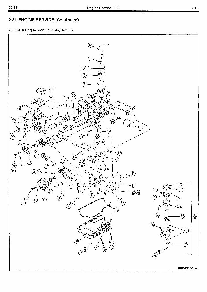
02-I 1 Engine Service, 2.3L 02-l 1
2.3L ENGINE SERVICE (Continued)
2.3L OHC Engine Components, Bottom
\ .
/’
PPDA24001 -A
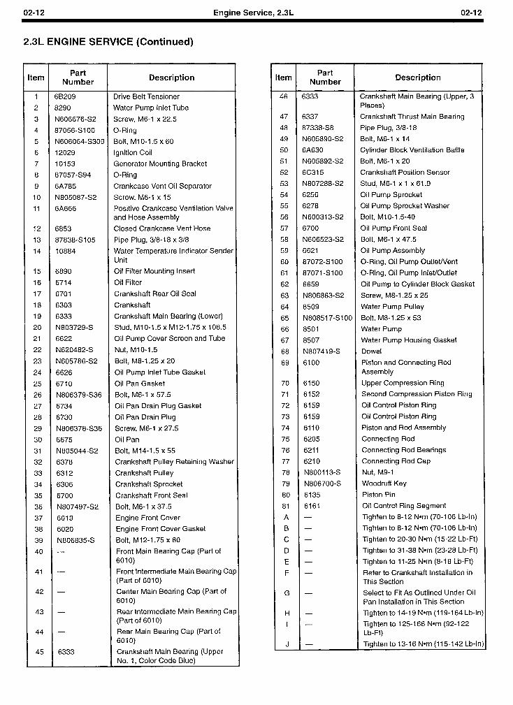
02-l 2 Engine Service, 2.3L 02-I 2
2.3L ENGINE SERVICE (Continued)
tern Part
Number Description
1 68209 Drive Belt Tensioner
2 8290 Water Pump Inlet Tube
3 N606676-S2 Screw, M6-1 x 22.5
4 87056SlOO O-Ring
5 N606064-S309 Bolt, MIO-1.5 x 60
6 12029 Ignition Coil
7 10153 Generator Mounting Bracket
8 87057-S94 O-Ring
9 6A785 Crankcase Vent Oil Separator
IO N805087-S2 Screw, M6-1 x 15
11 6A666 Positive Crankcase Ventilation Valve and Hose Assembly
12 6853 Closed Crankcase Vent Hose
13 87838-S105 Pipe Plug, 3/8-18 x 3/8
14 10884 Water Temperature Indicator Sender Unit
15 6890 Oil Filter Mounting Insert
16 6714 Oil Filter
17 6701 Crankshaft Rear Oil Seal
18 6303 Crankshaft
19 6333 Crankshaft Main Bearing (Lower)
20 N803729-S Stud, MIO-1.5 x M12-1.75 x 108.5
21 6622 Oil Pump Cover Screen and Tube
22 N620482-S Nut, Ml O-l .5
23 N605786S2 Bolt, M8-1.25 x 20
24 6626 Oil Pump Inlet Tube Gasket
25 6710 Oil Pan Gasket
26 N806379-S36 Bolt, M6-1 x 57.5
27 6734 Oil Pan Drain Plug Gasket
28 6730 Oil Pan Drain Plug
29 N806378-S36 Screw, M6-1 x 27.5
30 6675 Oil Pan
31 N805044-S2 Bolt, M14-1.5 x 55
32 6378 Crankshaft Pulley Retaining Washer
33 6312 Crankshaft Pulley
34 6306 Crankshaft Sprocket
35 6700 Crankshaft Front Seal
36 N80749742 Bolt, M6-1 x 37.5
37 6019 Engine Front Cover
38 6020 Engine Front Cover Gasket
39 N806835-S Bolt, M12-1.75 x 80
40 - Front Main Bearing Cap (Part of 6010)
41 - Front Intermediate Main Bearing Cat (Part of 6010)
42 - Center Main Bearing Cap (Part of 6010)
43 - Rear Intermediate Main Bearing Cat (Part of 6010)
44 - Rear Main Bearing Cap (Part of 6010)
45 6333 Crankshaft Main Bearing (Upper No. 1, Color Code Blue)
tern Part
Number Description
46 6333 Crankshaft Main Bearing (Upper, 3 Places)
47 6337 Crankshaft Thrust Main Bearing
48 87338S8 Pipe Plug, 318-18
49 N605890-S2 Bolt, M6-1 x 14
50 6A630 Cylinder Block Ventilation Baffle
51 N60589242 Bolt, M6-1 x 20
52 6C315 Crankshaft Position Sensor
53 N807288S2 Stud, M6-1 x 1 x 61.9
54 6256 Oil Pump Sprocket
55 6278 Oil Pump Sprocket Washer
56 N600313S2 Bolt, Ml O-l .5-40
57 6700 Oil Pump Front Seal
58 N606523S2 Bolt, M6-1 x 47.5
59 6621 Oil Pump Assembly
60 87072SlOO O-Ring, Oil Pump OutleWent
61 87071 -SlOO O-Ring, Oil Pump Inlet/Outlet
62 6659 Oil Pump to Cylinder Block Gasket
63 N806863-S2 Screw, M8-1.25 x 25
64 8509 Water Pump Pulley
65 N808517-SIOO Bolt, M8-1.25 x 53
66 8501 Water Pump
67 8507 Water Pump Housing Gasket
68 N807419-S Dowel
69 6100 Piston and Connecting Rod Assembly
70 6150 Upper Compression Ring
71 6152 Second Compression Piston Ring
72 6159 Oil Control Piston Ring
73 6159 Oil Control Piston Ring
74 6110 Piston and Rod Assembly
75 6205 Connecting Rod
76 6211 Connecting Rod Bearings
77 6210 Connecting Rod Cap
78 N800113-s Nut, M9-1
79 N806700-S Woodruff Key
80 6135 Piston Pin
81 6161 Oil Control Ring Segment
A - Tighten to 8-12 Nom (70-I 06 Lb-In)
B - Tighten to 8-12 Nom (70-106 Lb-In)
c - Tighten to 20-30 Nom (15-22 Lb-Ft)
D - Tighten to 31-38 Nom (23-28 Lb-Ft)
E - Tighten to II -25 Nom (8-I 8 Lb-Ft)
F - Refer to Crankshaft Installation in This Section
G - Select to Fit As Outlined Under Oil Pan Installation in This Section
H - Tighten to 14-l 9 Nom (119-l 64 Lb-lr
I - Tighten to 125-I 66 N*m (92-l 22 Lb-Ft)
J - Tighten to 13-16 Nom (115-142 Lb-lr
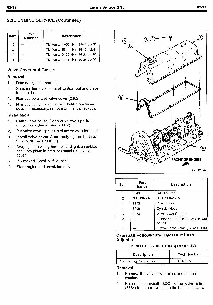
02-I 3 Engine Service, 2.3L 02-I 3
2.3L ENGINE SERVICE (Continued)
/ Itern 1 NiZer 1 Description
K -
L -
M -
N -
Tighten to 40-55 Nom (29-40 Lb-Ft)
Tighten to 1 O-14 Nom (89-l 24 Lb-In)
Tighten to 20-30 Nom (15-22 Lb-Ft)
Tighten to 41-49 Nom (30-36 Lb-Ft)
Valve Cover and Gasket
Removal 1. Remove ignition harness.
2. Snap ignition cables out of ignition coil and place to the side.
3. Remove bolts and valve cover (6582).
4. Remove valve cover gasket (6584) from valve cover. If necessary, remove oil filler cap (6766).
Installation
1. Clean valve cover. Clean valve cover gasket surface on cylinder head (6049).
2. Put valve cover gasket in place on cylinder head.
3. Install valve cover. Alternately tighten bolts to 9-13 Nom (84-120 lb-in).
4. Snap ignition wiring harness and ignition cables back into place in brackets attached to valve cover.
5. If removed, install oil filler cap.
6. Start engine and check for leaks. A239299A
Item
i B
Part Number
6766
N805087-S2
6582
6049
6584
Description
Oil Filler Cap
Screw, M6-1 xl 5
Valve Cover
Cylinder Head
Valve Cover Gasket
Tighten Until Ratchet Click Is Heard or Felt
Tighten to 9-13 Nom (84-120 Lb-In)
Camshaft Follower and Hydraulic Lash Adjuster
SPECIAL SERVICE TOOL(S) REQUIRED
r Description
I Valve Spring Compressor
I Tool Number I 1 T95T-6565-A I
Removal
1. Remove the valve cover as outlined in this section.
2. Rotate the camshaft (6250) so the rocker arm (6564) to be removed is on the heel of its cam.
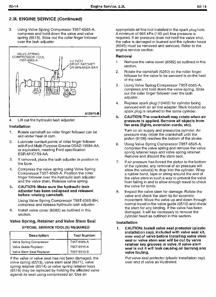
02-I 4 Engine Service, 2.3L 02-I 4
2.3L ENGINE SERVICE (Continued)
3. Using Valve Spring Compressor T95T-6565-A, compress and hold down the valve and valve spring (6513). Slide out the roller finger follower over the lash adjuster.
VALVE SPRING COMPRESSOR TOOL I I
T95T-6565-A l/2 INCH DRIVE RATCHET OR BREAKER BAR
Al 2975-B
4. Lift out the hydraulic lash adjuster.
Installation 1. Rotate camshaft so roller finger follower can be
slid under heel of cam.
2. Lubricate contact points of roller finger follower with Ford Multi-Purpose Grease DOAZ-19584-AA, or equivalent, meeting Ford specification ESR-Ml Cl 599AA.
3. If removed, place the lash adjuster in position in the bore.
4. Compress the valve spring using Valve Spring Compressor T95T-6565-A. Position the roller finger follower over the hydraulic lash adjuster and the valve stem. Release valve spring.
5. CAUTION: Make sure the hydraulic lash adjuster has been collapsed and released before rotating camshaft.
Using Valve Spring Compressor T88T-6565-BH, compress and release hydraulic lash adjuster.
6. Install valve cover (6582) as outlined in this section.
Valve Spring, Retainer and Valve Stem Seal
SPECIAL SERVICE TOOL(S) REQUIRED
Description I Tool Number
Valve Spring Compressor
Valve Guide Replacer
Valve Stem Seal Replacer
T95T-6565-A
T95T-651 O-A
T95T-651 O-B
If the valve or valve seat has not been damaged, the valve spring (6513), valve stem seal (6571), valve spring retainer (6514) or valve spring retainer keys (6518) may be replaced by holding the affected valve against its seat using compressed air. Use an
appropriate air line tool installed in the spark plug hole. A minimum of 965 kPa (140 psi) line pressure is required. If air pressure does not hold the valve shut, the valve is damaged or burned and the cylinder head (6049) must be removed and serviced. Refer to the engine service section.
Removal
1.
2.
3.
4.
5.
6.
7.
8.
Remove the valve cover (6582) as outlined in this section.
Rotate the camshaft (6250) so the roller finger follower for the valve to be serviced is on the heel of the cam.
Using Valve Spring Compressor T95T-6565-A, compress and hold down the valve spring. Slide out the roller finger follower over the lash adjuster.
Replace spark plug (12405) for cylinder being serviced with an air line adapter. Mark location so spark plug is returned to the same cylinder.
CAUTION:The crankshaft may rotate when air pressure is applied. Remove all objects from fan area (lights, extension cords, etc).
Turn on air supply and pressurize cylinder. Air pressure may rotate the crankshaft until the piston (6108) reaches the bottom of the stroke.
Using Valve Spring Compressor T95T-6565-A, compress the valve spring and remove the valve spring retainer keys and valve spring retainer. Remove and discard the stem seal.
If air pressure has forced the piston to the bottom of the cylinder, any removal of air pressure will allow the valve(s) to drop into the cylinder. Wrap a rubber band, tape or string around the end of the valve stem in such a way to prevent the valve from falling in and to allow enough travel to check the valve for binds.
Inspect the valve stem for damage. Rotate the valve and check the stem tip for eccentric movement. Move the valve up and down through normal travel in the valve guide (6510) and check the stem for any binding. If the valve has been damaged, it will be necessary to remove the cylinder head as outlined in this section.
Installation
1. CAUTION: Install valve seal protector (plastic installation cap), included with valve seal kit, over end of valve before installing valve stem seal or valve stem seal will be cut by valve retainer key grooves in valve. If valve stem seal is cut it will leak causing oil burning and valve fouling.
Put valve seal protector (plastic installation cap) over end of valve as illustrated.
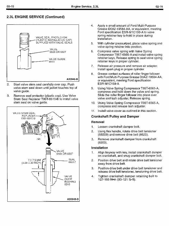
02-I 5 Engine Service, 2.3L 02-I 5
2.3L ENGINE SERVICE (Continued)
VALVE SEAL PROTECTOR (PLASTIC INSTALLATION CA SUPPLIED WITH VALVE SEA
W ,LS
VALVE / 6505 OR 6507
VALVE GUIDE 6510
A20946-B
2. Start valve stem seal carefully over cap. Push valve stem seal down until jacket touches top of valve guide.
3. Remove seal protector (plastic cap). Use Valve Stem Seal Replacer T95T-651 O-B to install valve stem seal on valve guide.
VALVE
VALVE 6505 OR 6507
7. (0.28-O.
A209489B
4.
5.
6.
7.
8.
9.
IO.
11.
Apply a small amount of Ford Multi-Purpose Grease DOA2-19584-AA, or equivalent, meeting Ford specification ESR-M 1 Cl 59-A to valve spring retainer key to hold in place during installation.
With cylinder pressurized, place valve spring and valve spring retainer into position.
Compress valve spring with Valve Spring Compressor T95T-6565-A and install valve spring retainer keys. Release spring to seat valve spring retainer keys in proper cylinder.
Release air pressure and remove air adapter. Install spark plug in proper cylinder.
Grease contact surfaces of roller finger follower with Ford Multi-Purpose Grease DOAZ-19584-AA, or equivalent, meeting Ford specification ESR-Ml Cl 59-A.
Using Valve Spring Compressor T95T-6565-A, compress and hold down the valve and spring. Slide the roller finger follower into place over valve and lash adjuster. Release spring.
Using Valve Spring Compressor T95T-6565-A, compress and release lash adjuster.
Install valve cover as outlined in this section.
Crankshaft Pulley and Damper
Removal
1. Loosen crankshaft damper bolt.
2. Using flex handle, rotate drive belt tensioner (6B209) and remove drive belt (8620).
3. Remove crankshaft damper from crankshaft (6303).
Installation
1. . Align keyway with key, install crankshaft damper on crankshaft, and snug crankshaft damper bolt.
2. Position drive belt and rotate drive belt tensioner away from drive belt.
3. Position drive belt under drive belt tensioner and release drive belt tensioner, tensioning drive belt.
4. Tighten crankshaft damper retaining bolt to 127-165 Nom (93-121 lb-ft).
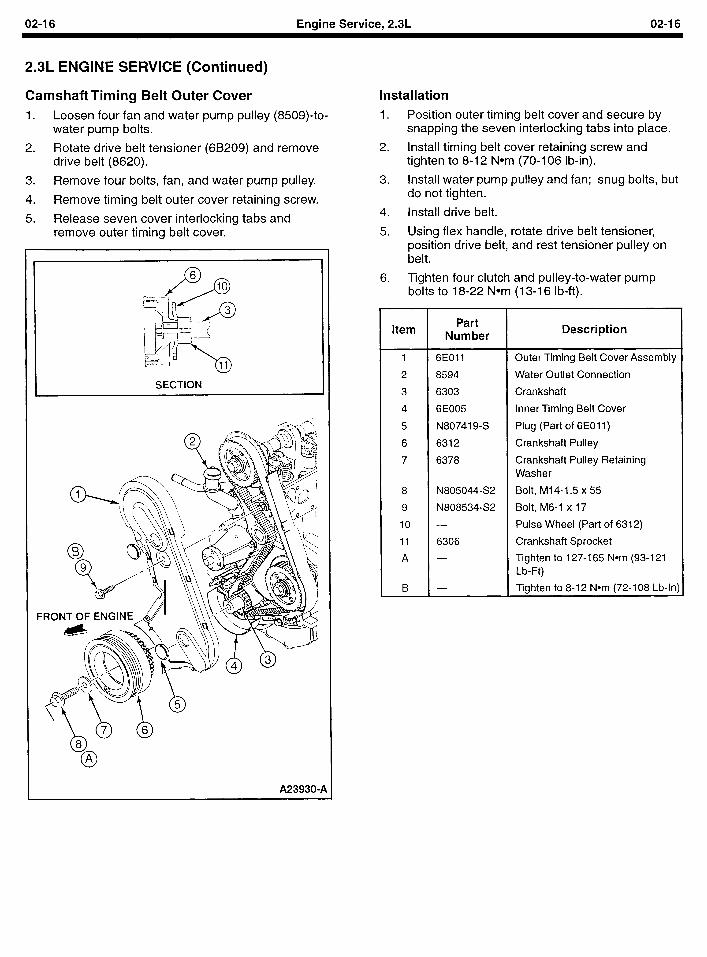
02-l 6 Engine Service, 2.3L 02-I 6
2.3L ENGINE SERVICE (Continued)
Camshaft Timing Belt Outer Cover 1. Loosen four fan and water pump pulley (8509)-to-
water pump bolts.
2. Rotate drive belt tensioner (6B209) and remove drive belt (8620).
3. Remove four bolts, fan, and water pump pulley.
4. Remove timing belt outer cover retaining screw.
5. Release seven cover interlocking tabs and remove outer timing belt cover.
SECTION .
A23930-1
installation
1. Position outer timing belt cover and secure by snapping the seven interlocking tabs into place.
2. Install timing belt cover retaining screw and tighten to 8-12 Nom (70-106 lb-in).
3. Install water pump pulley and fan; snug bolts, but do not tighten.
4. Install drive belt.
5. Using flex handle, rotate drive belt tensioner, position drive belt, and rest tensioner pulley on belt.
6. Tighten four clutch and pulley-to-water pump bolts to 18-22 Nom (13-I 6 lb-ft).
Item Part
Number Description
1 6EOll Outer Timing Belt Cover Assembly
2 8594 Water Outlet Connection
3 6303 Crankshaft
4 6E005 Inner Timing Belt Cover
5 N807419-S Plug (Part of 6E011)
6 6312 Crankshaft Pulley
7 6378 Crankshaft Pulley Retaining Washer
8 N805044-S2 Bolt, M14-1.5 x 55
9 N808534-S2 Bolt, M6-1 x 17
10 - Pulse Wheel (Part of 6312)
11 6306 Crankshaft Sprocket
A - Tighten to 127-165 Nom (93-l 21 Lb-Ft)
B - Tighten to 8-12 Nom (72-108 Lb-In)
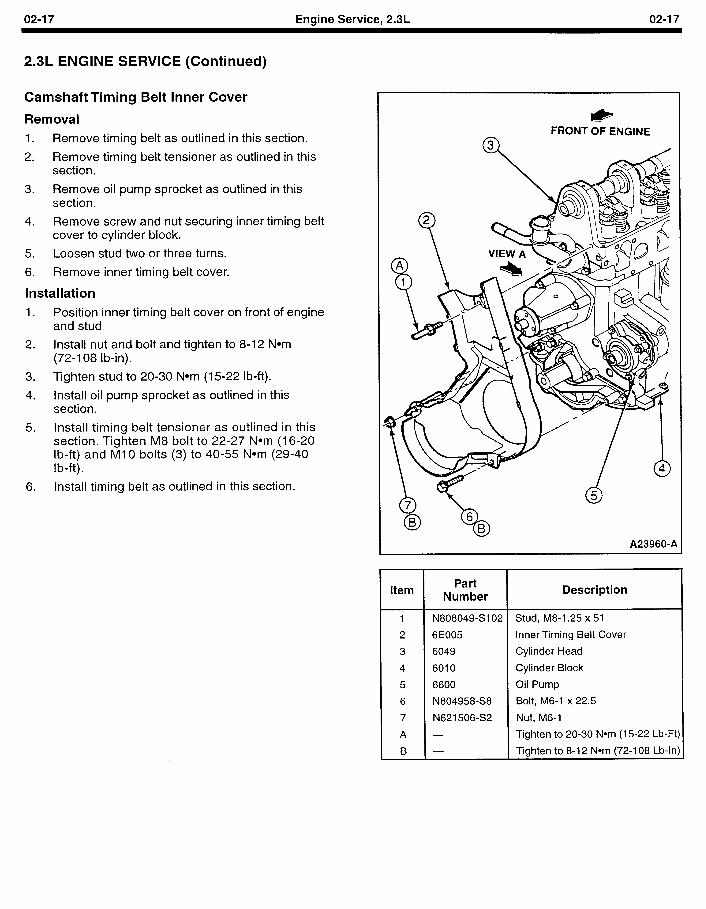
02-I 7 Engine Service, 2.3L 02-I 7
2.3L ENGINE SERVICE (Continued)
Camshaft Timing Belt Inner Cover
Removal
1. Remove timing belt as outlined in this section.
2. Remove timing belt tensioner as outlined in this section.
3. Remove oil pump sprocket as outlined in this section.
4. Remove screw and nut securing inner timing belt cover to cylinder block.
5. Loosen stud two or three turns.
6. Remove inner timing belt cover.
Installation
1. Position inner timing belt cover on front of engine and stud,
2. Install nut and bolt and tighten to 8-12 Nom (72-l 08 lb-in).
3. Tighten stud to 20-30 Nom (15-22 lb-ft).
4. Install oil pump sprocket as outlined in this section.
5. Install timing belt tensioner as outlined in this section. Tighten M8 bolt to 22-27 Nom (16-20 lb-ft) and Ml0 bolts (3) to 40-55 Nom (29-40 lb-ft).
6. Install timing belt as outlined in this section.
& FRONT OF ENGINE
A23960-A
Item Part
Number Description
1 N808049-S102 Stud, M8-1.25 x 51
2 6E005 Inner Timing Belt Cover
3 6049 Cylinder Head
4 6010 Cylinder Block
5 6600 Oil Pump
6 N804958-S8 Bolt, M6-1 x 22.5
7 N621506-S2 Nut, M6-1
A - Tighten to 20-30 Nom (15-22 Lb-Ft)
B - Tighten to 8-12 Nom (72-108 Lb-In)
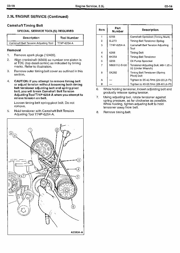
02-l 8 Engine Service, 2.3L 02-l 8
2.3L ENGINE SERVICE (Continued)
Camshaft Timing Belt
SPECIAL SERVICE TOOL(S) REQUIRED
Description I Tool Number I
1 Camshaft Belt Tension Adjusting Tool 1 T74P-6254-A
Removal
1. Remove spark plugs (I 2405).
2. Align crankshaft (6303) so number one piston is at TDC (top dead center) as indicated by timing marks. Refer to illustration.
3. Remove outer timing belt cover as outlined in this section.
4. CAUTION: If you attempt to remove timing belt or adjust tension without loosening both timing belt tensioner adjusting bolt and spring pivot bolt, you will break Camshaft Belt Tension Adjusting Tool T74P-6254-A when you attempt to relieve tension on belt.
Loosen timing belt spring pivot bolt. Do not remove.
5. Hold tensioner with Camshaft Belt Tension Adjusting Tool T74P-6254-A.
A239349A
Item
1 6256
2 6L273
3 T74P-6254-A
4 6268
5 6K254
6 6256
7 N800112-s100
6K282
Part Number
L
6. While holding tensioner, loosen adjusting bolt and gradually release spring tension.
7. Using adjusting tool, rotate tensioner against spring pressure, as far clockwise as possible. While holding, tighten adjusting bolt to hold tensioner away from belt.
8. Remove timing belt.
Description
Camshaft Sprocket (Timing Mark)
Timing Belt Tensioner Spring
Camshaft Belt Tension Adjusting Tool
Timing Belt
Timing Belt Tensioner
Oil Pump Sprocket
Tensioner Adjusting Bolt, M8-1.25 x 20 (Under Wrench)
Timing Belt Tensioner (Spring Pivot) Bolt
Tighten to 35-45 Nom (26-33 Lb-Ft)
Tighten to 40-55 Nom (29-40 Lb-Ft)
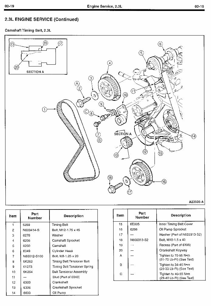
02-I 9 Engine Service, 2.3L 02-I 9
2.3L ENGINE SERVICE (Continued)
Camshaft Timing Belt, 2.3L
A23935-A
Item
1
2
3
4
5
6
7
8
9
IO
11
12
13
14
Part Number
6268
N600414-S
6278
6256
6250
6049
N80012-SIOO
6K282
61273
6K254
6303
6306
6600
Description Item
Timing Belt
Bolt, M12-1.75 x 45
Washer
Camshaft Sprocket
Camshaft
Cylinder Head
Bolt, M8-1.25 x 20
Timing Belt Tensioner Bolt
Timing Belt Tensioner Spring
Belt Tensioner Assembly
Stud (Part of 6049)
Crankshaft
Crankshaft Sprocket
Oil Pump
15
16
17
18
19
20
A
B
C
Part Number
6E005
6256
N600313-S2
Description
Inner Timing Belt Cover
Oil Pump Sprocket
Washer (Part of N600313-S2)
Bolt, MlO-1.5 x 40
Recess (Part of 6306)
Crankshaft Keyway
Tighten to 70-95 Nom (51-70 Lb-Ft) (See Text)
Tighten to 34-45 Nom (25-33 Lb-Ft) (See Text)
Tighten to 40-55 Nom (29-40 Lb-Ft) (See Text)
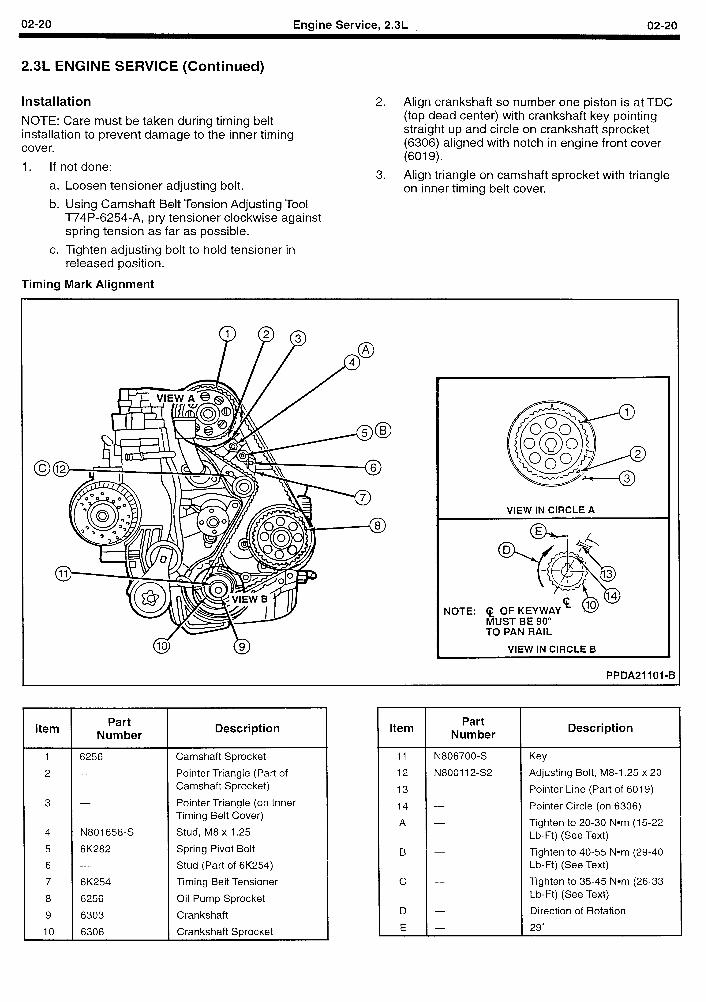
02-20 Engine Service, 2.3L 02-20
2.3L ENGINE SERVICE (Continued)
Installation 2. Align crankshaft so number one piston is at TDC
NOT ‘E: Care must be taken during timing belt insta llation to prevent damage to the inner timing cove r.
1. If not done:
a. Loosen tensioner adjusting bolt.
b. Using Camshaft Belt Tension Adjusting Tool T74P-6254-A, pry tensioner clockwise against spring tension as far as possible.
c. Tighten adjusting bolt to hold tensioner in released position.
(top dead center) with crankshaft key pointing straight up and circle on crankshaft sprocket (6306) aligned with notch in engine front cover (6019).
3. Align triangle on camshaft sprocket with triangle on inner timing belt cover.
Timing Mark Alignment
Item
1
2
3
4
5
6
7
8
9
IO
Part Number
6256
N801658-S
6K282
6K254
6256
6303
6306
Description
Camshaft Sprocket
Pointer Triangle (Part of Camshaft Sprocket)
Pointer Triangle (on Inner Timing Belt Cover)
Stud, M8 x 1.25
Spring Pivot Bolt
Stud (Part of 6K254)
Timing Belt Tensioner
Oil Pump Sprocket
Crankshaft
Crankshaft Sprocket
VIEW IN CIRCLE A
NOTE: q OF KEYW MUST BE 90” TO PAN RAIL
VIEW IN CIRCLE B
PPDA2 1101-B
Item Part
Number Description
11 N806700-S Key
12 N800112-s2 Adjusting Bolt, M8-1.25 x 20
13 - Pointer Line (Part of 6019)
14 - Pointer Circle (on 6306)
A - Tighten to 20-30 Nom (15-22 Lb-Ft) (See Text)
B - Tighten to 40-55 Nom (29-40 Lb-Ft) (See Text)
c - Tighten to 35-45 Nom (26-33 Lb-Ft) (See Text)
D - Direction of Rotation
E - 29”
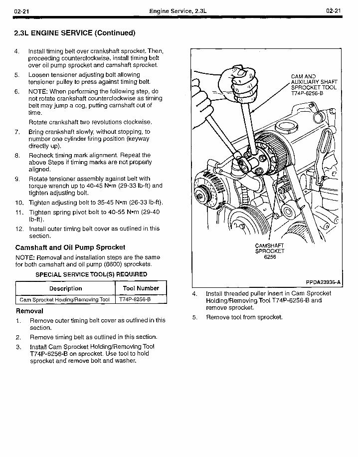
02-21 Engine Service, 2.3L
2.3L ENGINE SERVICE (Continued)
4.
5.
6.
7.
8.
9.
IO.
11.
12.
Install timing belt over crankshaft sprocket. Then, proceeding counterclockwise, install timing belt over oil pump sprocket and camshaft sprocket.
Loosen tensioner adjusting bolt allowing tensioner pulley to press against timing belt.
NOTE: When performing the following step, do not rotate crankshaft counterclockwise as timing belt may jump a cog, putting camshaft out of time.
Rotate crankshaft two revolutions clockwise.
Bring crankshaft slowly, without stopping, to number one cylinder firing position (keyway directly up).
Recheck timing mark alignment. Repeat the above Steps if timing marks are not properly aligned.
Rotate tensioner assembly against belt with torque wrench up to 40-45 Nom (29-33 lb-ft) and tighten adjusting bolt.
Tighten adjusting bolt to 35-45 Nom (26-33 lb-ft).
Tighten spring pivot bolt to 40-55 Nom (29-40 lb-ft).
Install outer timing belt cover as outlined in this section.
Camshaft and Oil Pump Sprocket NOTE: Removal and installation steps are the same for both camshaft and oil pump (6600) sprockets.
SPECIAL SERVICE TOOL(S) REQUIRED
Description Tool Number
Cam Sprocket Holding/Removing Tool T74P-6256-B I
Removal
1. Remove outer timing belt cover as outlined in this section.
2. Remove timing belt as outlined in this section.
3. Install Cam Sprocket Holding/Removing Tool T74P-6256-B on sprocket. Use tool to hold sprocket and remove bolt and washer.
CAMSHAR- SPROCKET
6256
PPDA23936-A
4. Install threaded puller insert in Cam Sprocket Holding/Removing Tool T74P-6256-B and remove sprocket.
5. Remove tool from sprocket.
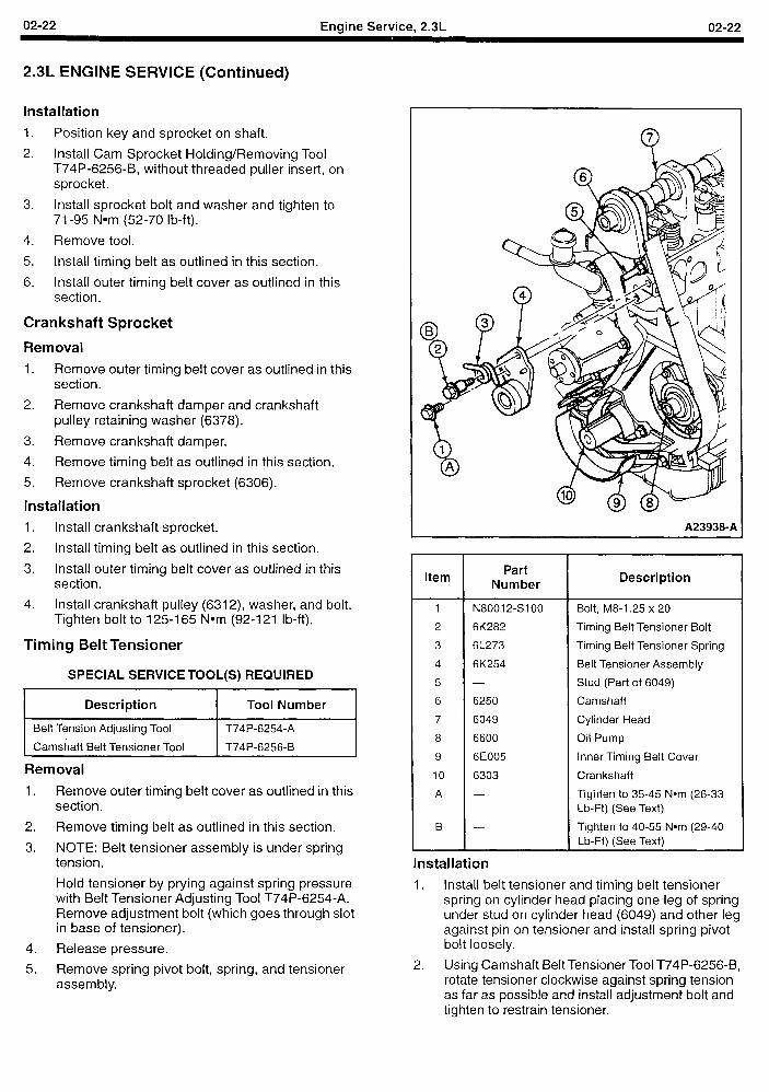
02-22 Engine Service, 2.3L 02-22
2.3L ENGINE SERVICE (Continued)
Installation
1. Position key and sprocket on shaft.
2. Install Cam Sprocket Holding/Removing Tool T74P-6256-B, without threaded puller insert, on sprocket.
3. Install sprocket bolt and washer and tighten to 71-95 Nom (52-70 lb-ft).
4. Remove tool.
5. Install timing belt as outlined in this section.
6. Install outer timing belt cover as outlined in this section.
Crankshaft Sprocket
Removal 1. Remove outer timing belt cover as outlined in this
section.
2. Remove crankshaft damper and crankshaft pulley retaining washer (6378).
3. Remove crankshaft damper.
4. Remove timing belt as outlined in this section.
5. Remove crankshaft sprocket (6306).
Installation
1. Install crankshaft sprocket.
2. Install timing belt as outlined in this section.
3. Install outer timing belt cover as outlined in this section.
4. Install crankshaft pulley (6312), washer, and bolt. Tighten bolt to 125-I 65 Nom (92-l 21 lb-ft).
Timing Belt Tensioner
SPECIAL SERVICE TOOL(S) REQUIRED
Description Tool Number
Belt Tension Adjusting Tool T74P-6254-A
Camshaft Belt Tensioner Tool T74P-6256-B
Removal
1. Remove outer timing belt cover as outlined in this section.
2. Remove timing belt as outlined in this section.
3. NOTE: Belt tensioner assembly is under spring tension.
Hold tensioner by prying against spring pressure with Belt Tensioner Adjusting Tool T74P-6254-A. Remove adjustment bolt (which goes through slot in base of tensioner).
4. Release pressure.
5. Remove spring pivot bolt, spring, and tensioner assembly.
A23938-A
Item Part
Number Description
1 N80012-SIOO Bolt, M8-1.25 x 20
2 6K282 Timing Belt Tensioner Bolt
3 6L273 Timing Belt Tensioner Spring
4 6K254 Belt Tensioner Assembly
5 - Stud (Part of 6049)
6 6250 Camshaft
7 6049 Cylinder Head
8 6600 Oil Pump
9 6E005 Inner Timing Belt Cover
IO 6303 Crankshaft
A - Tighten to 35-45 Nom (26-33 Lb-Ft) (See Text)
B - Tighten to 40-55 Nom (29-40 Lb-Ft) (See Text)
Installation
1. Install belt tensioner and timing belt tensioner spring on cylinder head placing one leg of spring under stud on cylinder head (6049) and other leg against pin on tensioner and install spring pivot bolt loosely.
2. Using Camshaft Belt Tensioner Tool T74P-6256-B, rotate tensioner clockwise against spring tension as far as possible and install adjustment bolt and tighten to restrain tensioner.
02-23 Engine Service, 2.3L 02-23
2.3L ENGINE SERVICE (Continued)
3. NOTE: Spring pivot bolt is to be tightened after Removal timing belt is installed. Adjusting bolt is tightened as part of timing belt installation.
Install timing belt as outlined in this section.
4. After installing timing belt, tighten spring pivot bolt to 40-55 Nom (29-40 I b-ft).
5. Install outer timing belt cover as outlined in this section.
Camshaft
SPECIAL SERVICE TOOL(S) REQUIRED
Description Tool Number
Valve Spring Compressor T95T-6565-A
Cam Sprocket Holding/Removing Tool T74P-6256-B
Front Seals Replacer T74P-6150-A
Front Cover Seal Remover T74P-6700-B
Remove outer timing belt cover as outlined in this section.
Remove valve cover (6582) as outlined in this section.
Rotate the camshaft (6250) so the rocker arm (6564) is on the heel of its cam.
Using Valve Spring Compressor T95T-6565-A, compress valve springs (6513) and remove all roller finger followers.
Remove camshaft sprocket using Cam Sprocket Holding/Removing Tool T74P-6256-B.
Remove camshaft seal using Front Cover Seal Remover T74P-6700-B.
Remove camshaft retainer plate (two screws).
CAUTION: Be careful to avoid damaging journals and lobes.
Remove camshaft.
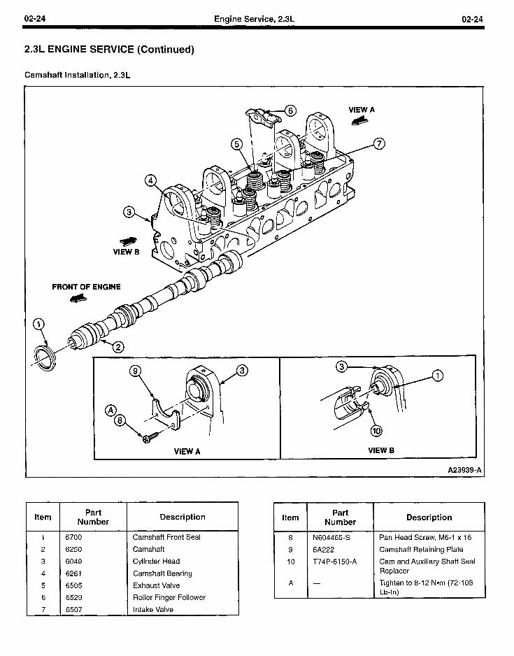
02-24 Engine Service, 2.3L 02-24
2.3L ENGINE SERVICE (Continued)
Camshaft Installation, 2.3L
FRONT OF ENGINE
,
A23939-A
VIEW A I VIEW B
Item Part
Number Description
6700 Camshaft Front Seal
6250 Camshaft
6049 Cylinder Head
6261 Camshaft Bearing
6505 Exhaust Valve
6529 Roller Finger Follower
6507 Intake Valve
I I Item Part
Number Description
8 N604465-S
9 6A222
10 T74P-6150-A
A
Pan Head Screw, M6-1 x 16
Camshaft Retaining Plate
Cam and Auxiliary Shaft Seal Replacer
Tighten to 8-12 Nom (72-108 Lb-In)
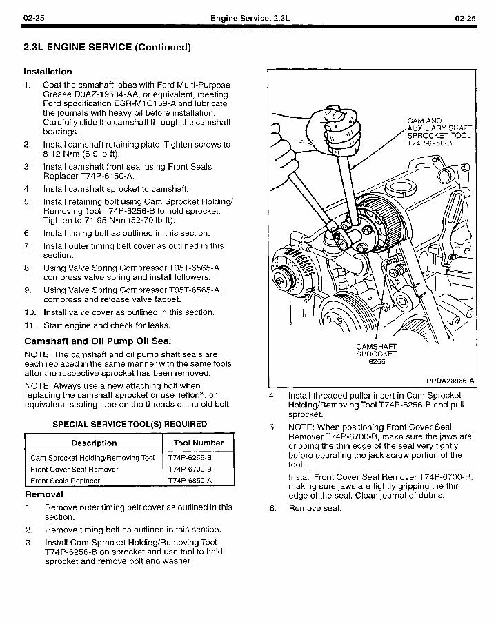
02-25 Engine Service, 2.3L 02-25
2.3L ENGINE SERVICE (Continued)
Installation
1. Coat the camshaft lobes with Ford Multi-Purpose Grease DOAZ-19584-AA, or equivalent, meeting Ford specification ESR-Ml Cl 59-A and lubricate the journals with heavy oil before installation. Carefully slide the camshaft through the camshaft bearings.
2. Install camshaft retaining plate. Tighten screws to 8-12 Nom (6-9 lb-ft).
3. Install camshaft front seal using Front Seals Replacer T74P-6150-A.
4. Install camshaft sprocket to camshaft.
5. Install retaining bolt using Cam Sprocket Holding/ Removing Tool T74P-6256-B to hold sprocket. Tighten to 71-95 Nom (52-70 lb-ft).
6. Install timing belt as outlined in this section.
7. Install outer timing belt cover as outlined in this section.
8. Using Valve Spring Compressor T95T-6565-A compress valve spring and install followers.
9. Using Valve Spring Compressor T95T-6565-A, compress and release valve tappet.
IO. Install valve cover as outlined in this section.
11. Start engine and check for leaks.
Camshaft and Oil Pump Oil Seal NOTE: The camshaft and oil pump shaft seals are each replaced in the same manner with the same tools after the respective sprocket has been removed.
NOTE: Always use a new attaching bolt when replacing the camshaft sprocket or use Teflon@, or equivalent, sealing tape on the threads of the old bolt.
SPECIAL SERVICE TOOL(S) REQUIRED
Description Tool Number
Cam Sprocket Holding/Removing Tool T74P-6256-B
Front Cover Seal Remover T74P-6700-B
Front Seals Replacer T74P-6850-A
Removal
1. Remove outer timing belt cover as outlined in this section.
2. Remove timing belt as outlined in this section,
3. Install Cam Sprocket Holding/Removing Tool T74P-6256-B on sprocket and use tool to hold sprocket and remove bolt and washer.
CAMSHAm SPROCKET
6256
- ’
PPDA23936-A
4. Install threaded puller insert in Cam Sprocket Holding/Removing Tool T74P-6256-B and pull sprocket.
5. NOTE: When positioning Front Cover Seal Remover T74P-6700-B, make sure the jaws are gripping the thin edge of the seal very tightly before operating the jack screw portion of the tool.
Install Front Cover Seal Remover T74P-6700-B, making sure jaws are tightly gripping the thin edge of the seal. Clean journal of debris.
6. Remove seal.
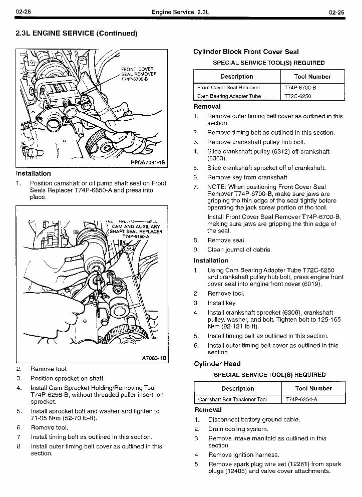
02-26 Engine Service, 2.3L 02-26
2.3L ENGINE SERVICE (Continued)
FRONT COVER SEAL REMOVER T74P-6700-B
PPDA7081-1 B
Installation
1. Position camshaft or oil pump shaft seal on Front Seals Replacer T74P-6850-A and press into place.
A70834 B
2. Remove tool.
3. Position sprocket on shaft.
4. Install Cam Sprocket Holding/Removing Tool T74P-6256-B, without threaded puller insert, on sprocket.
5. Install sprocket bolt and washer and tighten to 71-95 Nom (52-70 lb-ft).
6. Remove tool.
7. Install timing belt as outlined in this section.
8. install outer timing belt cover as outlined in this section.
Cylinder Block Front Cover Seal
SPECIAL SERVICE TOOL(S) REQUIRED
Description Tool Number
Front Cover Seal Remover T74P-6700-B
Cam Bearing Adapter Tube T72C-6250 ,
Removal
1. Remove outer timing belt cover as outlined in this section.
2. Remove timing belt as outlined in this section.
3. Remove crankshaft pulley hub bolt.
4. Slide crankshaft pulley (6312) off crankshaft (6303).
5. Slide crankshaft sprocket off of crankshaft.
6. Remove key from crankshaft.
7. NOTE: When positioning Front Cover Seal Remover T74P-6700-B, make sure jaws are gripping the thin edge of the seal tightly before operating the jack screw portion of the tool.
Install Front Cover Seal Remover T74P-6700-B, making sure jaws are gripping the thin edge of the seal.
8. Remove seal.
9. Clean journal of debris.
Installation
1. Using Cam Bearing Adapter Tube T72C-6250 and crankshaft pulley hub bolt, press engine front cover seal into engine front cover (6019).
2. Remove tool.
3. Install key.
4. Install crankshaft sprocket (6306), crankshaft pulley, washer, and bolt. Tighten bolt to 125-I 65 Nom (92-l 21 lb-ft).
5. Install timing belt as outlined in this section.
6. Install outer timing belt cover as outlined in this section.
Cylinder Head
SPECIAL SERVICE TOOL(S) REQUIRED
Description Tool Number
Camshaft Belt Tensioner Tool T74P-6254-A
Removal
1. Disconnect battery ground cable.
2. Drain cooling system.
3. Remove intake manifold as outlined in this section.
4. Remove ignition harness.
5. Remove spark plug wire set (12281) from spark plugs (12405) and valve cover attachments.
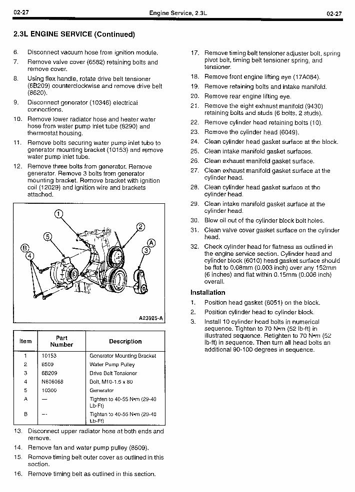
02-27 Engine Service, 2.3L 02-27
2.3L ENGINE SERVICE (Continued)
6.
7.
8.
9.
IO.
11.
12.
Disconnect vacuum hose from ignition module.
Remove valve cover (6582) retaining bolts and remove cover.
Using flex handle, rotate drive belt tensioner (6B209) counterclockwise and remove drive belt (8620).
Disconnect generator (10346) electrical connections.
Remove lower radiator hose and heater water hose from water pump inlet tube (8290) and thermostat housing.
Remove bolts securing water pump inlet tube to generator mounting bracket (10153) and remove water pump inlet tube.
Remove three bolts from generator. Remove generator. Remove 3 bolts from generator mounting bracket. Remove bracket with ignition coil (12029) and ignition wire and brackets attached.
A23925-A
Item Part
Number Description
1 10153 Generator Mounting Bracket
2 8509 Water Pump Pulley
3 68209 Drive Belt Tensioner
4 N606068 Bolt, Ml O-l .5 x 80
5 10300 Generator
A - Tighten to 40-55 Nom (29-40 Lb-Ft)
B - Tighten to 40-55 Nom (29-40 Lb-Ft)
13. Disconnect upper radiator hose at both ends and remove.
14. Remove fan and water pump pulley (8509).
15. Remove timing belt outer cover as outlined in this section.
16. Remove timing belt as outlined in this section.
17.
18.
19.
20.
21.
22.
23.
24.
25.
26.
27.
Remove timing belt tensioner adjuster bolt, spring pivot bolt, timing belt tensioner spring, and tensioner.
Remove front engine lifting eye (17A084).
Remove retaining bolts and intake manifold.
Remove rear engine lifting eye.
Remove the eight exhaust manifold (9430) retaining bolts and studs (6 bolts, 2 studs).
Remove cylinder head retaining bolts (10).
Remove the cylinder head (6049).
Clean cylinder head gasket surface at the block.
Clean intake manifold gasket surfaces.
Clean exhaust manifold gasket surface.
Clean exhaust manifold gasket surface at the cylinder head.
28. Clean cylinder head gasket surface at the cylinder head.
29. Clean intake manifold gasket surface at the cylinder head.
30. Blow oil out of the cylinder block bolt holes.
31. Clean valve cover gasket surface on the cyl head.
32. Check cylinder head for flatness as outlined
inder
in the engine service section. Cylinder head and cylinder block (6010) head gasket surface should be flat to 0.08mm (0.003 inch) over any 152mm (6 inches) and flat within 0.15mm (0.006 inch) overall.
Installation
1. Position head gasket (6051) on the block.
2. Position cylinder head to cylinder block.
3. Install IO cylinder head bolts in numerical sequence. Tighten to 70 Nom (52 lb-ft) in illustrated sequence. Retighten to 70 Nom (52 lb-ft) in sequence. Then turn all head bolts an additional 90-I 00 degrees in sequence.
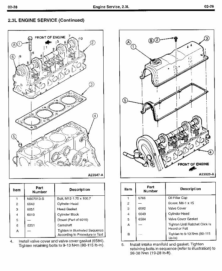
02-28 Engine Service, 2.3L 02-28
2.3L ENGINE SERVICE (Continued)
FRONT OF EN
A239479A
Item Part
Number
1 N807013-S
2 6049
3 6051
4 6010
5 -
6 6251
A -
Description
Bolt, M12-1.75 x 100.7
Cylinder Head
Head Gasket
Cylinder Block
Dowel (Part of 6010)
Camshaft
Tighten in Illustrated Sequence According to Procedure in Text
4. Install valve cover and valve cover gasket (6584). Tighten retaining bolts to 9-13 Nom (80-U 5 lb-in).
A23929-A
Item Part
Number
6766
6582
6049
6584
Description
Oil Filler Cap
Screw, M6-1 x 15
Valve Cover
Cylinder Head
Valve Cover Gasket
Tighten Until Ratchet Click Is Heard or Felt
Tighten to 9-13 Nom (80-l 15 Lb-In)
5. Install intake manifold and gasket. Tighten retaining bolts in sequence (refer to illustration) tc 26-38 Nom (19-28 lb-ft).
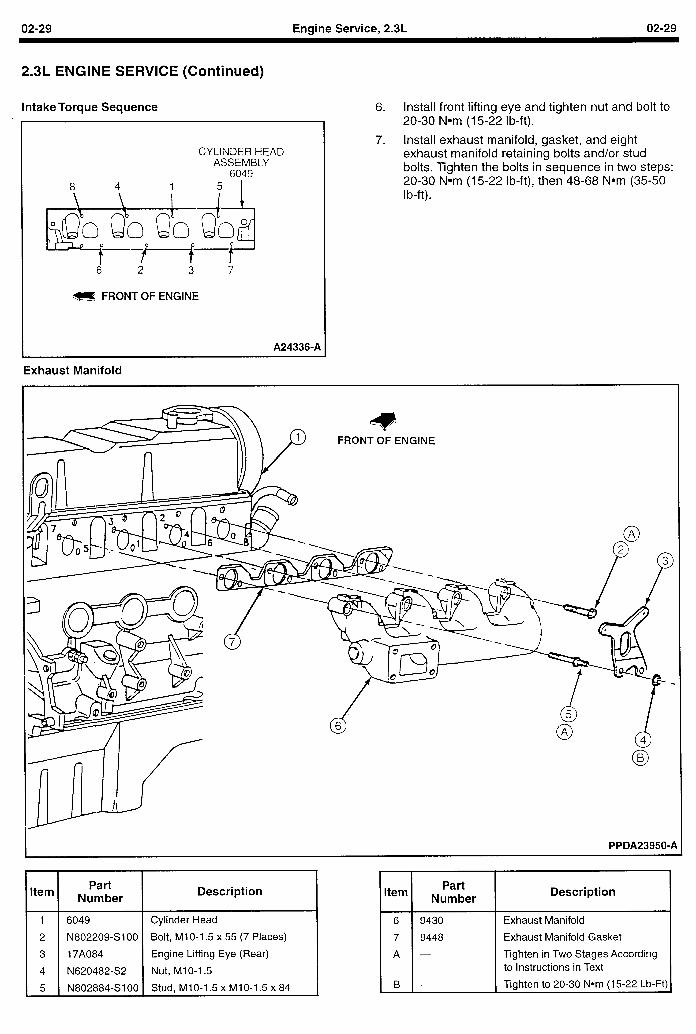
02-29 Engine Service, 2.3L 02-29
2.3L ENGINE SERVICE (Continued)
Intake Torque Sequence
CYLINDER HEAD ASSEMBLY
6049 8 4 1 5 I
m FRONT OF ENGINE
A24336-A
Exhaust Manifold
6. Install front lifting eye and tighten nut and bolt to 20-30 Nom (15-22 lb-ft).
7. Install exhaust manifold, gasket, and eight exhaust manifold retaining bolts and/or stud bolts. Tighten the bolts in sequence in two steps: 20-30 Nom (15-22 lb-ft), then 48-68 Nom (35-50 I b-ft) .
PPDA23950-P
I I Item Part
Number Description
1 6049 Cylinder Head
2 N802209-SlOO Bolt, MIO-1.5 x 55 (7 Places)
3 17A084 Engine Lifting Eye (Rear)
4 N620482-S2 Nut, Ml O-l 5
5 N802884-SIOO Stud, MlO-1.5 x MIO-1.5 x 84
I I Item Part
Number Description
Exhaust Manifold
Exhaust Manifold Gasket
Tighten in Two Stages According to Instructions in Text
Tighten to 20-30 Nom (15-22 Lb-Ft)
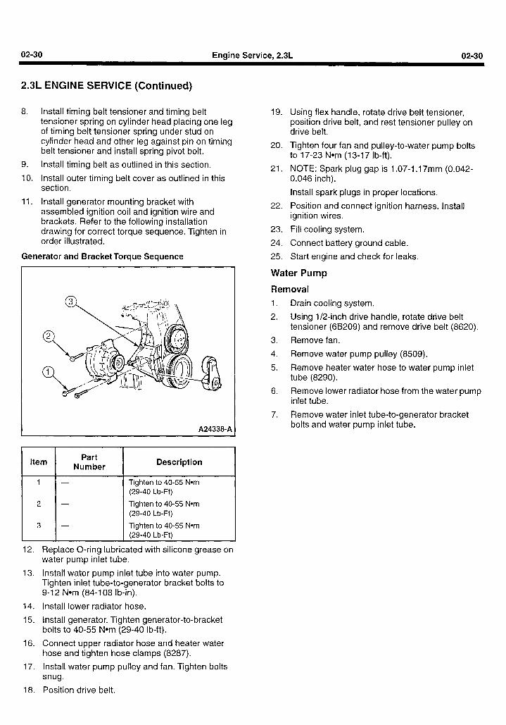
02-30 Engine Service, 2.3L 02-30
2.3L ENGINE SERVICE (Continued)
8. install timing belt tensioner and timing belt tensioner spring on cylinder head placing one leg of timing belt tensioner spring under stud on cylinder head and other leg against pin on timing belt tensioner and install spring pivot bolt.
9. Install timing belt as outlined in this section.
10. Install outer timing belt cover as outlined in this section.
11. Install generator mounting bracket with assembled ignition coil and ignition wire and brackets. Refer to the following installation drawing for correct torque sequence. Tighten in order illustrated.
Generator and Bracket Torque Sequence
A24338-A
I I Item Part
Number Description
1
2
1 3
Tighten to 40-55 Nom (29-40 Lb-Ft)
Tighten to 40-55 Nom (29-40 Lb-Ft)
Tighten to 40-55 Nom (29-40 Lb-Ftl
12. Replace O-ring lubricated with silicone grease on water pump inlet tube.
13. Install water pump inlet tube into water pump. Tighten inlet tube-to-generator bracket bolts to 9-12 Nom (84-108 lb-in).
14. Install lower radiator hose.
15. Install generator. Tighten generator-to-bracket bolts to 40-55 Nom (29-40 lb-ft).
16. Connect upper radiator hose and heater water hose and tighten hose clamps (8287).
19. Using flex handle, rotate drive belt tensioner, position drive belt, and rest tensioner pulley on drive belt.
20. Tighten four fan and pulley-to-water pump bolts to 17-23 Nom (13-l 7 lb-ft).
21. NOTE: Spark plug gap is 1.07-I .17mm (0.042- 0.046 inch).
Install spark plugs in proper locations.
22. Position and connect ignition harness. Install ignition wires.
23. Fill cooling system.
24. Connect battery ground cable.
25. Start engine and check for leaks.
Water Pump
Removal
1. Drain cooling system.
2. Using l/2-inch drive handle, rotate drive belt tensioner (6B209) and remove drive belt (8620).
3. Remove fan.
4. Remove water pump pulley (8509).
5. Remove heater water hose to water pump inlet tube (8290).
6. Remove lower radiator hose from the water pump inlet tube.
7. Remove water inlet tube-to-generator bracket bolts and water pump inlet tube.
17. Install water pump pulley and fan. Tighten bolts snug.
18. Position drive belt.
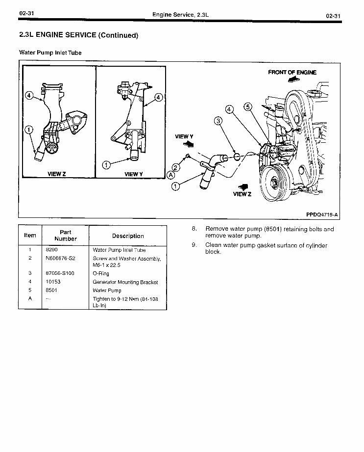
02-31 Engine Service, 2.3L 02-31
2.3L ENGINE SERVICE (Continued)
Water Pump Inlet Tube
L FRONT OF ENGINE
&
PPDQ4719-A
Item Part
Number Description
8290
N606676-S2
87056-SIOO
10153
8501
Water Pump Inlet Tube
Screw and Washer Assembly, M6-1 x 22.5
O-Ring
Generator Mounting Bracket
Water Pump
Tighten to 9-l 2 Nom (84-l 08 Lb-In)
8. Remove water pump (8501) retaining bolts and remove water pump.
9. Clean water pump gasket surface of cylinder block.
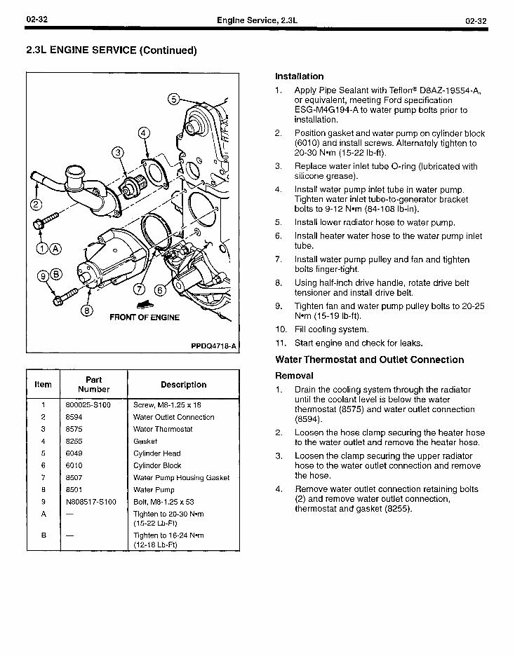
02-32 Engine Service, 2.3L 02-32
2.3L ENGINE SERVICE (Continued)
FRONT OF ENGINE
PPDQ4718-A
Item
1
2
3
4
5
6
7
8
9
A
B
Part Number
800025SIOO
8594
8575
8255
6049
6010
8507
8501
N808517-SIOO
-
-
Description
Screw, M8-1.25 x 18
Water Outlet Connection
Water Thermostat
Gasket
Cylinder Head
Cylinder Block
Water Pump Housing Gasket
Water Pump
Bolt, M8-1.25 x 53
Tighten to 20-30 Nom (15-22 Lb-Ft)
Tighten to 16-24 Nom (12-l 8 Lb-Ft)
Installation
1.
2.
3.
4.
5.
6.
7.
8.
9.
10.
11.
Apply Pipe Sealant with Teflon@ D8AZ-19554-A, or equivalent, meeting Ford specification ESG-M4G194-A to water pump bolts prior to installation.
Position gasket and water pump on cylinder block (6010) and install screws. Alternately tighten to 20-30 Nom (15-22 lb-ft).
Replace water inlet tube O-ring (lubricated with silicone grease).
Install water pump inlet tube in water pump. Tighten water inlet tube-to-generator bracket bolts to 9-12 Nom (84-108 lb-in).
Install lower radiator hose to water pump.
Install heater water hose to the water pump inlet tube.
Install water pump pulley and fan and tighten bolts finger-tight.
Using half-inch drive handle, rotate drive belt tensioner and install drive belt.
Tighten fan and water pump pulley bolts to 20-25 Nom (15-I 9 lb-ft).
Fill cooling system.
Start engine and check for leaks.
Water Thermostat and Outlet Connection
Removal
1. Drain the cooling system through the radiator until the coolant level is below the water thermostat (8575) and water outlet connection (8594).
2. Loosen the hose clamp securing the heater hose to the water outlet and remove the heater hose.
3. Loosen the clamp securing the upper radiator hose to the water outlet connection and remove the hose.
4. Remove water outlet connection retaining bolts (2) and remove water outlet connection, thermostat and gasket (8255).
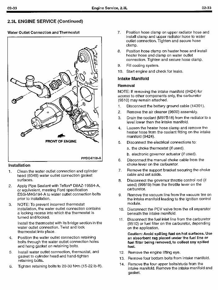
02-33 Engine Service, 2.3L 02-33
2.3L ENGINE SERVICE (Continued)
Water Outlet Connection and Thermostat
FRONT OF ENGINE N 5.
PPDQ4718-A
Installation
1. Clean the water outlet connection and cylinder head (6049) water outlet connection gasket surfaces.
2. Apply Pipe Sealant with Teflon@ D8AZ-19554-A, or equivalent, meeting Ford specification ESG-M4G194-A to water outlet connection bolts prior to installation.
3. NOTE: To prevent incorrect thermostat installation, the water outlet connection contains a locking recess into which the thermostat is turned and locked.
Install the thermostat with its bridge section in the water outlet connection. Twist and lock thermostat into place.
4. Position the water outlet connection retaining bolts through the water outlet connection holes and hang gasket on retaining bolts.
5. Install water outlet connection, thermostat, and gasket to cylinder head and hand-tighten retaining bolts.
6. Tighten retaining bolts to 20-30 Nom (15-22 lb-ft).
7. Position hose clamp on upper radiator hose and install clamp and upper radiator hose to water outlet connection. Tighten and secure hose clamp.
8. Position hose clamp on heater hose and install heater hose and clamp on water outlet connection. Tighten and secure hose clamp.
9. Fill cooling system.
10. Start engine and check for leaks.
Intake Manifold
Removal
NOTE: If removing the intake manifold (9424) for access to other components only, the carburetor (9510) may remain attached.
1.
2.
3.
4.
6.
7.
8.
9.
10.
11.
12.
13.
14.
Disconnect the battery ground cable (14301).
Remove the air cleaner (9600) assembly.
Drain the coolant (M97B18) from the radiator to a level lower than the intake manifold.
Loosen the heater hose clamp and remove the heater hose from the coolant fitting on the intake manifold (9424).
Disconnect the electrical connections to:
a. the choke thermostat (if used).
b. electronic governor actuator (if used).
Disconnect the manual choke cable from the choke lever on the carburetor.
Remove the support bracket securing the choke cable and set aside.
Disconnect the governor throttle control rod (if used) (99819) from the throttle lever on the carburetor.
Remove the vacuum line from the vacuum tee on the intake manifold leading to the ignition control module.
Disconnect the PCV valve from the oil separator beneath the intake manifold.
Disconnect the fuel inlet line from the carburetor (9510) or fuel filter on the carburetor, depending on the application.
Caution: Avoid spilling fuel on hot surfaces. Use an absorbent rag placed under the fuel line or fuel filter being removed, to collect any spilled fuel.
Remove the engine lifting eye.
Remove four bottom bolts from intake manifold.
Remove the four upper bolts/studs from the intake manifold. Remove the intake manifold and qasket.
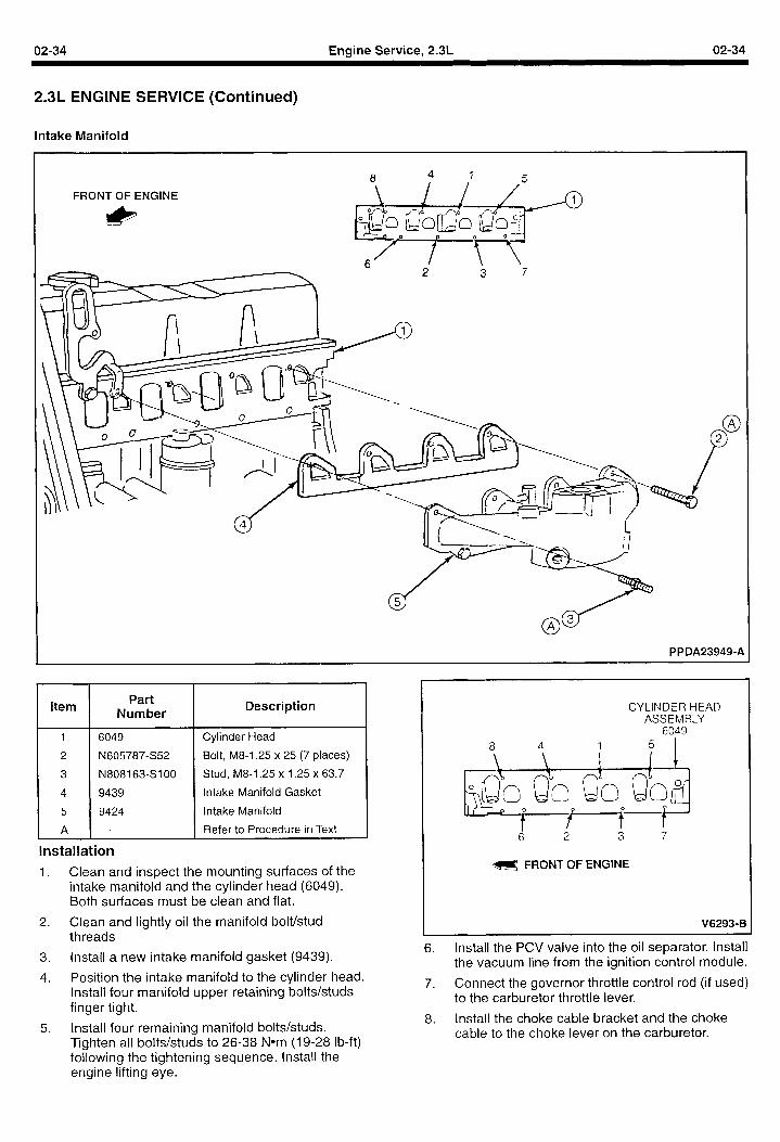
02-34 Engine Service, 2.3L 02-34
2.3L ENGINE SERVICE (Continued)
Intake Manifold
FRONT OF ENGINE
PPDA23949-A
Item Part
Number
6049
N605787-S52
N808163-Sl OO
9439
9424
Description
Cylinder Head
Bolt, M8-1.25 x 25 (7 places)
Stud, M8-1.25 x 1.25 x 63.7
Intake Manifold Gasket
Intake Manifold
Refer to Procedure in Text
Installation
1. Clean and inspect the mounting surfaces of the intake manifold and the cylinder head (6049). Both surfaces must be clean and flat.
2. Clean and lightly oil the manifold bolt/stud threads
3. Install a new intake manifold gasket (9439).
CYLINDER HEAD ASSEMBLY
6049
8 4 1 5 I
B FRONT OF ENGINE
V6293-B
6. Install the PCV valve into the oil separator. Install the vacuum line from the ignition control module.
4. Position the intake manifold to the cylinder head. Install four manifold upper retaining bolts/studs
7. Connect the governor throttle control rod (if used)
finger tight. to the carburetor throttle lever.
5. Install four remaining manifold bolts/studs. 8. Install the choke cable bracket and the choke
Tighten all bolts/studs to 26-38 Nom (19-28 lb-ft) cable to the choke lever on the carburetor.
following the tightening sequence. Install the engine lifting eye.
02-35 Engine Service, 2.3L 02-35
2.3L ENGINE SERVICE (Continued)
9. Connect the electrical connections at the choke thermostat (if used) and electronic governor actuator (if used).
IO. Install the hose clamp on the heater hose and connect the heater hose to the fitting on the intake manifold.
11. Install the air cleaner assembly.
12. Fill the cooling system.
13. Install the negative battery cable.
14. Start the engine and check for leaks
Carburetor
Removal 5.
1.
2.
3.
4.
5.
6.
7.
8.
Disconnect the negative battery cable.
Remove the air cleaner assembly (9600).
Disconnect the electrical connections to:
a. the choke thermostat (if used).
b. electronic governor actuator (if used).
Disconnect the manual choke cable from the choke lever on the carburetor.
Disconnect the governor throttle control rod (if used) (99819) from the throttle lever on the carburetor.
Disconnect the fuel inlet line from the carburetor or fuel filter on the carburetor (9510), depending on the application.
Caution: Avoid spilling fuel on hot surfaces. Use an absorbent rag placed under the fuel line or fuel filter being removed, to collect any spilled fuel.
Remove the retaining nuts from the studs securing the base of the carburetor.
Remove the carburetor and carburetor base gasket (9447) from the intake manifold (9424).
NOTE: If the carburetor is not being serviced and is going to be placed back on the intake manifold, do not turn the carburetor upside down. This may cause any float bowl sediment to restrict or clog carburetor passages or prevent the inlet needle and seat assembly from closing. The carburetor’s operation may be affected.
Installation 1. Clean and inspect the mounting surfaces of the
intake manifold and the base of the carburetor. Both surfaces must be clean and free of any gasket material.
2. Install the carburetor base gasket and carburetor on the intake manifold.
3. Install the retaining nuts on the studs securing the base of the carburetor.
4. Reconnect the fuel inlet line to the carburetor or fuel filter on the carburetor, depending on the application.
Reconnect the governor throttle control rod (if used) to the throttle lever on the carburetor. Perform governor adjustment after carburetor installation is complete. Refer to the Auxiliary Systems Section.
6.
7.
8.
9.
Reconnect the manual choke cable to the choke lever on the carburetor. Adjust cable so that full opening and closing of the choke plate is possible.
Reconnect the electrical connections to:
a. the choke thermostat (if used).
b. electronic governor actuator (if used).
Install the air cleaner assembly.
Start the engine, let it warm to operating temperature, and perform idle mixture and speed adjustments.
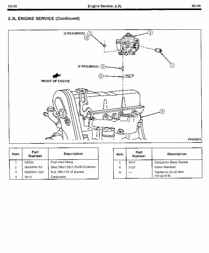
02-36 Engine Service, 2.3L 02-36
2.3L ENGINE SERVICE (Continued)
I& FRONT OF ENGINE
PPDOOOl
Part Number
Description
1 9A520
2 N800896-S2
3 N620041 -S51
4 9510
Fuel Inlet Fitting
Stud, M8x1.25x1.25~38 (2 places)
Nut, M8x1.25 (2 places)
Carburetor
Part Number
Description
5 9447
6 9424
A -
Carburetor Base Gasket
Intake Manifold
Tighten to 20-30 Nom (15-22 I b-ft)
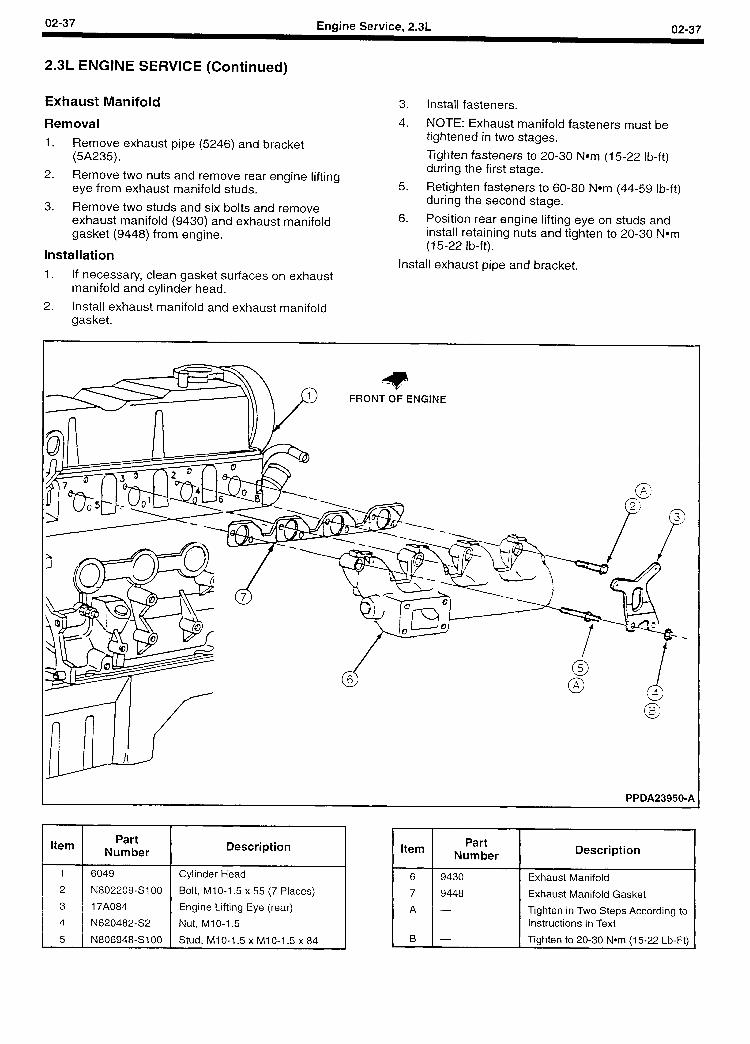
02-37 Engine Service, 2.3L 02-37
2.3L ENGINE SERVICE (Continued)
Exhaust Manifold
Removal
1. Remove exhaust pipe (5246) and bracket (5A235).
2. Remove two nuts and remove rear engine lifting eye from exhaust manifold studs.
3. Remove two studs and six bolts and remove exhaust manifold (9430) and exhaust manifold gasket (9448) from engine.
Installation
1. If necessary, clean gasket surfaces on exhaust manifold and cylinder head.
2. Install exhaust manifold and exhaust manifold gasket.
3. Install fasteners.
4. NOTE: Exhaust manifold fasteners must be tightened in two stages.
Tighten fasteners to 20-30 Nom (15-22 lb-ft) during the first stage.
5. Retighten fasteners to 60-80 Nom (44-59 lb-ft) during the second stage.
6. Position rear engine lifting eye on studs and install retaining nuts and tighten to 20-30 Nom (15-22 lb-ft).
Install exhaust pipe and bracket.
PPDA23950-A
Item
l
Part Description Part
Number Item Number Description
6049 Cylinder Head 6 9430 Exhaust Manifold
N802209-SIOO Bolt, MIO-1.5 x 55 (7 Places) 7 9448 Exhaust Manifold Gasket
17A084 Engine Lifting Eye (rear) A - Tighten in Two Steps According to
N620482-S2 Nut, Ml O-l .5 Instructions in Text
N806948-Sl OO Stud, Ml O-1.5 x Ml O-l .5 x 84 B - Tighten to 20-30 Nom (15-22 Lb-Ft)
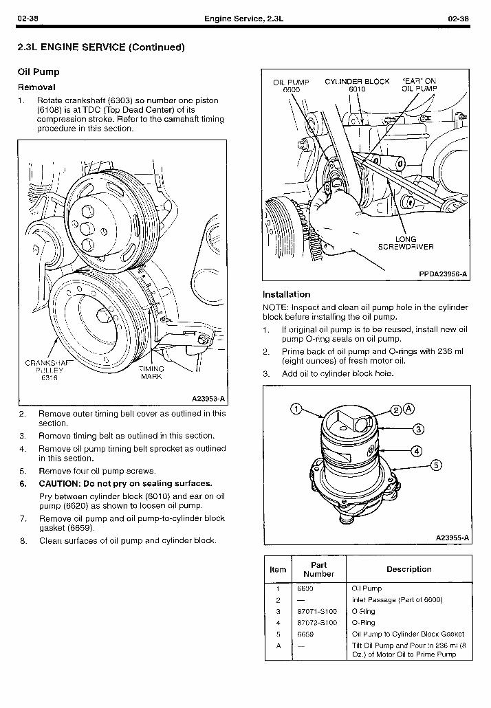
02-38 Engine Service, 2.3L 02-38
2.3L ENGINE SERVICE (Continued)
Oil Pump
Removal
1. Rotate crankshaft (6303) so number one piston (6108) is at TDC (Top Dead Center) of its compression stroke. Refer to the camshaft timing procedure in this section.
6316 MARK
A239530A
2. Remove outer timing belt cover as outlined in this section.
;
3. Remove timing belt as outlined in this section.
4. Remove oil pump timing belt sprocket as outlined in this section.
5. Remove four oil pump screws.
6. CAUTION: Do not pry on sealing surfaces.
Pry between cylinder block (6010) and ear on oil pump (6620) as shown to loosen oil pump.
7. Remove oil pump and oil pump-to-cylinder block gasket (6659).
8. Clean surfaces of oil pump and cylinder block.
OIL PUMP CYLINDER BLOCK “EAR” ON 6600 6010 OIL PUMP
1 r
\
LONG SCREWDRIVER
PPDA23956-A
Installation
NOTE: Inspect and clean oil pump hole in the cylinder block before installing the oil pump.
1. If original oil pump is to be reused, install new oil pump O-ring seals on oil pump.
2. Prime back of oil pump and O-rings with 236 ml (eight ounces) of fresh motor oil.
3. Add oil to cylinder block hole.
A23955-A
I 5 1 6659
Description
Oil Pump
Inlet Passage (Part of 6600)
O-Ring
O-Ring
Oil Pump to Cylinder Block Gasket
Tilt Oil Pump and Pour In 236 ml (8 Oz.) of Motor Oil to Prime Pump
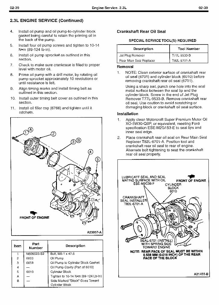
02-39 Engine Service, 2.3L 02-39
2.3L ENGINE SERVICE (Continued)
4.
9.
IO.
11.
Install oil pump and oil pump-to-cylinder block gasket being careful to retain the priming oil in the back of the pump.
Install four oil pump screws and tighten to 1 O-14 Nom (89-l 24 lb-in).
Install oil pump sprocket as outlined in this section.
Check to make sure crankcase is filled to proper level with motor oil.
Prime oil pump with a drill motor, by rotating oil pump sprocket approximately IO revolutions or until resistance is felt.
Align timing marks and install timing belt as outlined in this section.
Install outer timing belt cover as outlined in this section.
Install oil filler cap (6766) and tighten until it ratchets.
FRONT OF ENGINE
A23957-A
Item Part
Number Description
1 N606523-S2 Bolt, M6-1 x 47.5
2 6600 Oil Pump
3 6659 Oil Pump to Cylinder Block Gasket
4 - Oil Pump Cavity (Part of 6010)
5 6010 Cylinder Block
A - Tighten to 1 O-14 Nom (89-l 24 Lb-In)
B - Side Marked “Block” Goes Toward Cylinder Block
Crankshaft Rear Oil Seal
SPECIAL SERVICE TOOL(S) REQUIRED
Description I Tool Number I
Jet Plug Remover
Rear Main Seal Replacer
T77L-9533-B
T82L-670 1 -A
Removal
1. NOTE: Clean exterior surface of crankshaft rear oil seal (6701) and cylinder block (6010) before removing crankshaft rear oil seal (6701).
Using a sharp awl, punch one hole into the seal metal surface between the seal lip and the cylinder block. Screw in the end of Jet Plug Remover T77L-9533-B. Remove crankshaft rear oil seal. Use caution to avoid scratching or damaging block or crankshaft oil seal surface.
Installation
1. Apply clean Motorcraft Super Premium Motor Oil X0-5W30-QSP, or equivalent, meeting Ford specification ESE-M2G153-E to seal lips and inner seal edge.
2. Place crankshaft rear oil seal on Rear Main Seal Replacer T82L-6701 -A. Position tool and crankshaft rear oil seal to rear of engine. Alternate bolt tightening to seat the crankshaft rear oil seal properly.
LUBRICATE SEAL AND SEAL * MATING SURFACE WITH OIL FRONT OF ENGINE
ESE-M2C39-F
n
CYLINDER BLOCK
6010
NOTE: REAR FACE OF SEAL MUST BE WITHIN 0.508 MM (0.019 INCH) OF THE REAR FACE OF THE BLOCK
A21 455-E
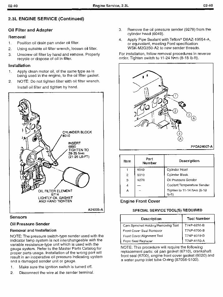
02-40 Engine Service, 2.3L 02-40
2.3L ENGINE SERVICE (Continued)
Oil Filter and Adapter
Removal
1. Position oil drain pan under oil filter.
2. Using suitable oil filter wrench, loosen oil filter.
3. Unscrew oil filter by hand and remove. Properly recycle or dispose of oil in filter.
Installation
1. Apply clean motor oil, of the same type as is being used in the engine, to the oil filter gasket.
2. NOTE: Do not tighten filter with oil filter wrench.
Install oil filter and tighten by hand.
INSERT 6890
/ TIGHTEN TO 28-35 Nom
CYLINDER BLOCK
/ 6010
w 6714 LIGHTLY OIL GASKET AND HAND TIGHTEN
A24005-A SPECIAL SERVICE TOOL(S) REQUIRED
Sensors
Oil Pressure Sender
Removal and Installation
NOTE: The pressure switch-type sender used with the indicator lamp system is not interchangeable with the variable resistance-type unit which is used with the gauge system. Refer to the Master Parts Catalog for proper parts usage. Installation of the wrong part will result in an inoperative oil pressure indicating system and a damaged sender unit or gauge.
1. Make sure the ignition switch is turned off.
2. Disconnect the wire at the sender terminal.
3. Remove the oil pressure sender (9278) from the cylinder head (6049).
4. Apply Pipe Sealant with Teflon@ D8AZ-19554-A, or equivalent, meeting Ford specification WSK-M2G350-A2 to new sender threads.
For installation, follow removal procedures in reverse order. Tighten switch to 11-24 Nom (8-l 8 lb-ft).
0 A PPDA24007-A
Item
1
2
3
4
A
Part Number
6049
6010
9278
-
-
Description
Cylinder Head
Cylinder Block
Oil Pressure Sender
Coolant Temperature Sender
Tighten to 11-14 Nom (8-18 I b-ft)
Engine Front Cover
Description I Tool Number I
Holding/Removing Tool T74P-6256-B
Front Cover Seal Remover T74P-6700-B
Front Cover Alignment Tool T74P-6019-B
Front Seal Replacer T74P-6150-A
NOTE: This procedure will require the following replacement parts: oil pan gasket (6710), crankshaft front seal (6700), engine front cover gasket (6020) and a water pump inlet tube O-ring (87056-5100).
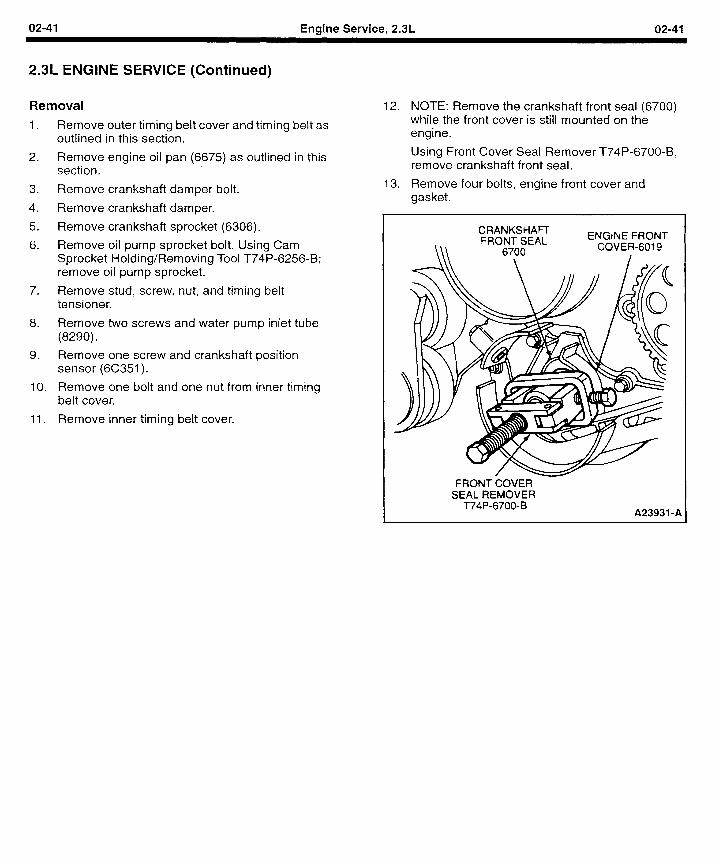
02-41 Engine Service, 2.3L 02-41
2.3L ENGINE SERVICE (Continued)
Removal
1. Remove outer timing belt cover and timing belt as outlined in this section.
12. NOTE: Remove the crankshaft front seal (6700) while the front cover is still mounted on the engine.
2. Remove engine oil pan (6675) as outlined in this section.
Using Front Cover Seal Remover T74P-6700-B, remove crankshaft front seal.
3. Remove crankshaft damper bolt. 13. Remove four bolts, engine front cover and gasket.
4. Remove crankshaft damper.
5. Remove crankshaft sprocket (6306).
6. Remove oil pump sprocket bolt. Using Cam Sprocket Holding/Removing Tool T74P-6256-B; remove oil pump sprocket.
7. Remove stud, screw, nut, and timing belt tensioner.
8. Remove two screws and water pump inlet tube (8290).
9. Remove one screw and crankshaft position sensor (6C351).
IO. Remove one bolt and one nut from inner timing belt cover.
11. Remove inner timing belt cover.
CRANKSHAn FRONT SEAL ENGtNE FRONT
\\\ 6700 COVER-601 9 I
FRONT COVER SEAL REMOVER
T74P-6700-B A23931 -A
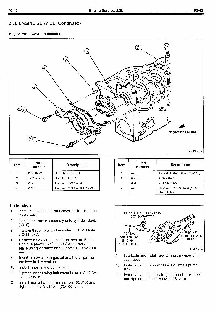
02-42 Engine Service, 2.3L 02-42
2.3L ENGINE SERVICE (Continued)
Engine Front Cover Installation
& T OF ENGINE
A23932-A
Item Part
Number Description Item
807288-S2 Stud, M6-1 x 61.9
N807497-S2 Bolt, M6-1 x 37.5
6019 Engine Front Cover
6020 Engine Front Cover Gasket
Installation
1.
2.
3.
4.
5.
6.
7.
Install a new engine front cover gasket in engine front cover.
Install front cover assembly onto cylinder block (6010).
Tighten three bolts and one stud to 13-16 Nom (1 O-l 2 lb-ft).
Position a new crankshaft front seal on Front Seals Replacer T74P-6150-A and press into place using vibration damper bolt. Remove bolt and tool.
Install a new oil pan gasket and the oil pan as outlined in this section.
Install inner timing belt cover.
Tighten inner timing belt cover bolts to 8-12 Nom (72-l 08 lb-in).
Install crankshaft position sensor (6C315) and tighten bolt to 8-12 Nom (72-l 08 lb-in).
Part Number
6303
6010
Description
Dowel Bushing (Part of 6010)
Crankshaft
Cylinder Block
Tighten to 13-I 6 Nom (120- 144 Lb-In)
9. Lubricate and install new O-ring on water pump inlet tube.
10. Install water pump inlet tube into water pump (8501).
11. Install water inlet tube-to-generator bracket bolts and tighten to 9-12 Nom (84-108 lb-in).
CRANKSHAFT POSITION A
‘ER
A239339A
8.
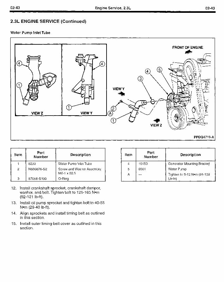
02-43 Engine Service, 2.3L 02-43
2.3L ENGINE SERVICE (Continued)
Water Pump Inlet Tube
FRONT OF ENGINE lb
fF
PPDQ4719-A
I 1 I
I I Item Part
Number Description
1 8290
2 N606676-S2
3 87056-Sl OO
Water Pump Inlet Tube
Screw and Washer Assembly, M6-1 x 22.5
O-Ring
12. Install crankshaft sprocket, crankshaft damper, washer, and bolt. Tighten bolt to 125-l 65 Nom (92-l 21 lb-ft).
13. Install oil pump sprocket and tighten bolt to 40-55 Nom (29-40 lb-ft).
14. Align sprockets and install timing belt as outlined in this section.
I I Item Part
Number Description
4 10153
5 8501
A -
Generator Mounting Bracke!
Water Pump
Tighten to 9-l 2 Nom (84-l 08 Lb-In)
15. Install outer timing belt cover as outlined in this section.
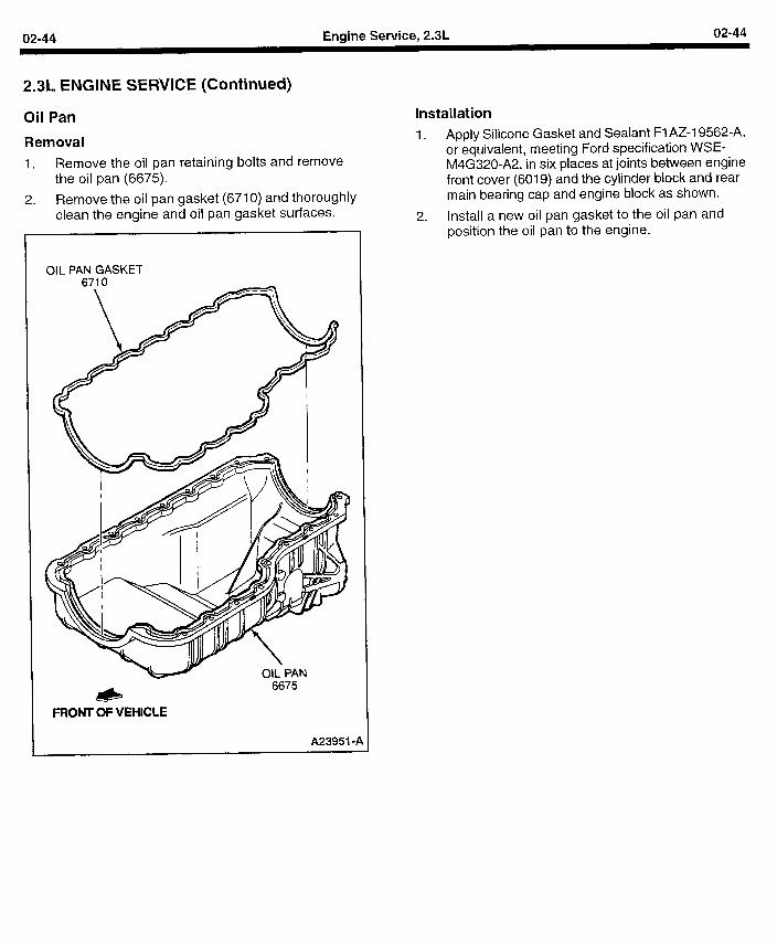
02-44 Engine Service, 2.3L 02-44
2.3L ENGINE SERVICE (Continued)
Oil Pan
Removal
1. Remove the oil pan retaining bolts and remove the oil pan (6675).
2. Remove the oil pan gasket (6710) and thoroughly clean the engine and oil pan gasket surfaces.
OIL PAN GASKET
6675
FRONT OF VEHICLE
A239514
Installation
1. Apply Silicone Gasket and Sealant Fl AZ-l 9562-A, or equivalent, meeting Ford specification WSE- M4G320-A2, in six places at joints between engine front cover (6019) and the cylinder block and rear main bearing cap and engine block as shown.
2. Install a new oil pan gasket to the oil pan and position the oil pan to the engine.
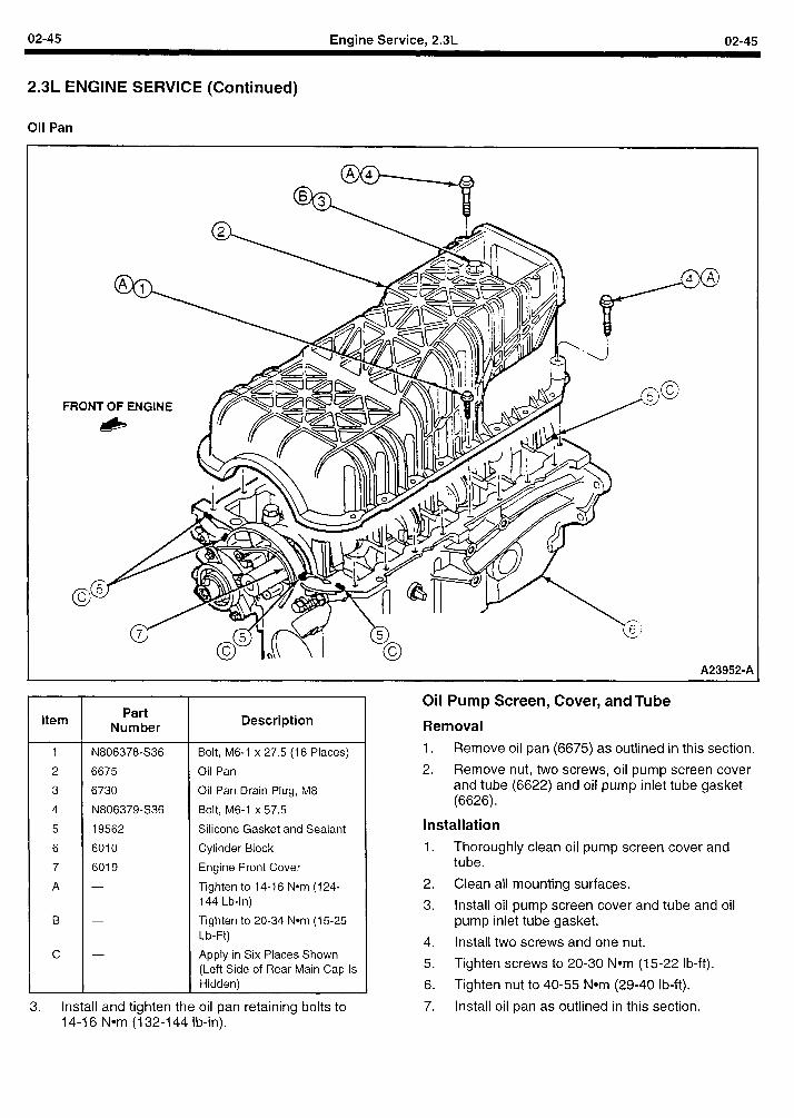
02-45 Engine Service, 2.3L 02-45
2.3L ENGINE SERVICE (Continued)
Oil Pan
A239529A
Item
1
2
3
4
5
6
7
A
B
@
Part Number
N806378-S36
6675
6730
N806379-S36
19562
6010
6019
Description
Bolt, M6-I x 27.5 (16 Places)
Oil Pan
Oil Pan Drain Plug, M8
Bolt, M6-1 x 57.5
Silicone Gasket and Sealant
Cylinder Block
Engine Front Cover
Tighten to 14-16 Nom (124- 144 Lb-In)
Tighten to 20-34 Nom (15-25 Lb-Ft)
Apply in Six Places Shown (Left Side of Rear Main Cap Is Hidden)
3. install and tighten the oil pan retaining bolts to 14-l 6 Nom (132-144 lb-in).
Oil Pump Screen, Cover, and Tube
Removal
1. Remove oil pan (6675) as outlined in this section.
2. Remove nut, two screws, oil pump screen cover and tube (6622) and oil pump inlet tube gasket (6626).
Installation
1. Thoroughly clean oil pump screen cover and tube.
2. Clean all mounting surfaces.
3. Install oil pump screen cover and tube and oil pump inlet tube gasket.
4. Install two screws and one nut.
5. Tighten screws to 20-30 Nom (15-22 lb-ft).
6. Tighten nut to 40-55 Nom (29-40 lb-ft).
7. Install oil pan as outlined in this section.
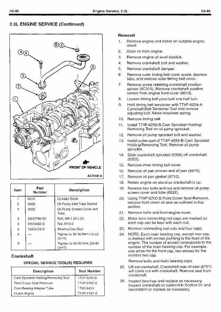
02-46 Engine Service, 2.3L 02-46
2.3L ENGINE SERVICE (Continued)
FRONT OF VEH1CL.E
A239584
Item Part
Number
1 6010
2 6626
3 6622
4 N605786-S2
5 N620482-S
6 N803729-S
A -
B -
Description
Cylinder Block
Oil Pump Inlet Tube Gasket
Oil Pump Screen Cover and Tube
Bolt, M8-1.25 x 20
Nut, Ml O-5
Bearing Cap Stud
Tighten to 20-30 Nom (15-22 Lb-Ft)
Tighten to 40-55 Nom (29-40 Lb-Ft)
Crankshaft
SPECIAL SERVICE TOOL(S) REQUIRED
I Description I Tool Number
I Cam Sprocket Holding/Removing Tool n Front Cover Seal Remover
Cam Bearing Adapter Tube
Clutch Aligner
T74P-6256-B
T74P-6700-B
T72C-6250
T7l P-71 37-H
Removal
1.
2.
3.
4.
5.
6.
7.
8.
9.
10.
11.
12.
13.
14.
15.
16.
17.
18.
19.
20.
21.
22.
23.
24.
25.
26.
Remove engine and install on suitable engine stand.
Drain oil from engine.
Remove engine oil level dipstick.
Remove crankshaft bolt and washer.
Remove crankshaft damper.
Remove outer timing belt cover screw, depress tabs, and remove outer timing belt cover.
Remove screw retaining crankshaft position sensor (6C315). Remove crankshaft position sensor from engine front cover (6019).
Loosen timing belt pivot bolt one-half turn.
Hold timing belt tensioner with T74P-6254-A Camshaft Belt Tensioner Tool and remove adjusting bolt. Relax tensioner spring.
Remove timing belt.
Install T74P-6256-B Cam Sprocket Holding/ Removing Tool on oil pump sprocket.
Remove oil pump sprocket bolt and washer.
Install puller part of T74P-6256-B Cam Sprocket Holding/Removing Tool. Remove oil pump sprocket.
Slide crankshaft sprocket (6306) off crankshaft (6303).
Remove inner timing belt cover.
Remove oil pan screws and oil pan (6675).
Remove oil pan gasket (6710).
Rotate engine on stand so crankshaft is up.
Remove two bolts and nut and remove oil pump screen cover and tube (6622).
Using T74P-6700-B Front Cover Seal Remover, remove front cover oil seal as outlined in this section.
Remove bolts and front engine cover.
Make sure connecting rod caps are marked so each cap can be kept with each rod.
Remove connecting rod nuts and four caps.
NOTE: Each main bearing cap, except rear cap, is marked with arrows pointing to the front of the engine. The number of arrows corresponds to the number of the main bearing cap. For example, one arrow for the front cap, two arrows for the number two cap.
Remove bolts and main bearing caps.
Lift out crankshaft. Crankshaft rear oil seal (6701) will come out with crankshaft. Remove seal from crankshaft.
Inspect bearings and replace as necessary. Inspect crankshaft as outlined in Section 01 and recondition or replace as necessary.
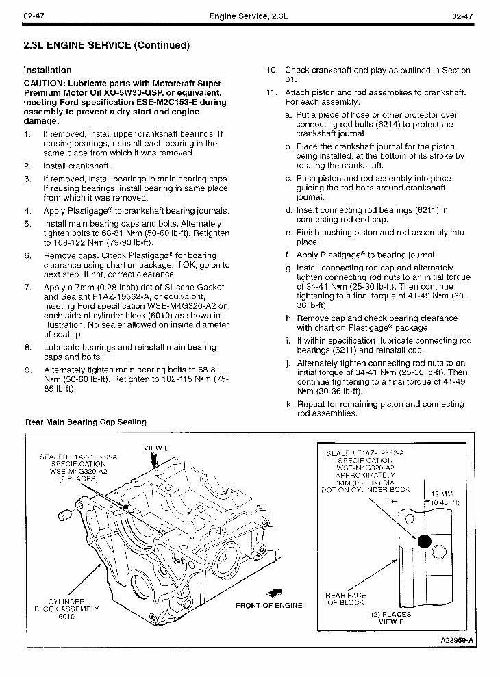
02-47 Engine Service, 2.3L 02-47
2.3L ENGINE SERVICE (Continued)
Installation
CAUTION: Lubricate parts with Motorcraft Super Premium Motor Oil XO+W30=QSP, or equivalent, meeting Ford specification ESE-M2C153-E during assembly to prevent a dry start and engine damage.
1. if removed, install upper crankshaft bearings. If reusing bearings, reinstall each bearing in the same place from which it was removed.
2. Install crankshaft.
3. If removed, install bearings in main bearing caps. If reusing bearings, install bearing in same place from which it was removed.
4. Apply Plastigage@ to crankshaft bearing journals.
5. Install main bearing caps and bolts. Alternately tighten bolts to 68-81 Nom (50-60 lb-ft). Retighten to 108-122 Nom (79-90 lb-ft).
6. Remove caps. Check Plastigage@ for bearing clearance using chart on package. If OK, go on to next step. If not, correct clearance.
7. Apply a 7mm (0.28-inch) dot of Silicone Gasket and Sealant Fl AZ-l 9562-A, or equivalent, meeting Ford specification WSE-M4G320-A2 on each side of cylinder block (6010) as shown in illustration. No sealer allowed on inside diameter of seal lip.
8. Lubricate bearings and reinstall main bearing caps and bolts.
9. Alternately tighten main bearing bolts to 68-81 Nom (50-60 lb-ft). Retighten to 102-115 Nom (75- 85 lb-ft).
Rear Main Bearing Cap Sealing
10. Check crankshaft end play as outlined in Section 01.
11. Attach piston and rod assemblies to crankshaft. For each assembly:
a. Put a piece of hose or other protector over connecting rod bolts (6214) to protect the crankshaft journal.
b. Place the crankshaft journal for the piston being installed, at the bottom of its stroke by rotating the crankshaft.
c. Push piston and rod assembly into place guiding the rod bolts around crankshaft journal.
d. Insert connecting rod bearings (6211) in connecting rod end cap.
e. Finish pushing piston and rod assembly into place.
f. Apply Plastigage@ to bearing journal.
g. Install connecting rod cap and alternately tighten connecting rod nuts to an initial torque of 34-41 Nom (25-30 lb-ft). Then continue tightening to a final torque of 41-49 Nom (30- 36 lb-ft).
h. Remove cap and check bearing clearance with chart on Plastigage@ package.
i. If within specification, lubricate connecting rod bearings (6211) and reinstall cap.
j. Alternately tighten connecting rod nuts to an initial torque of 34-41 Nom (25-30 lb-ft). Then continue tightening to a final torque of 41-49 Nom (30-36 lb-ft).
k. Repeat for remaining piston and connecting rod assemblies.
VIEW B SE
CYLINDER ILOCK ASSEMBLY FRONT OF ENGI NE
SEALER FlAZ-19562-A SPECIFICATION
WSE-M4G320-A2 APPROXIMATELY 7MM (0.28 IN) DIA.
DOT ON CYLINDER BOCK 12 MM
REAR FACE OF BLOCK
(2) PLACES VIEW B
A23959-A
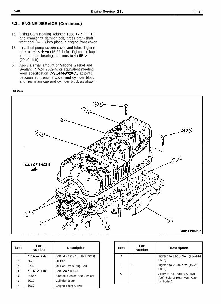
02-48 Engine Service, 2.3L 02-48
2.3L ENGINE SERVICE (Continued)
12. Using Cam Bearing Adapter Tube T72C6250and crankshaft damper bolt, press crankshaftfront seal (6700) into place in engine front cover.
13. Install oil pump screen cover and tube. Tightenbolts to 20-30 Nom (15-22 lb-ft). Tighten pickuptube-to-main bearing cap nuts to 40-55 Nom(29-40 I b-ft).
14. Apply a small amount of Silicone Gasket andSealant Fl AZ-l 9562-A, or equivalent meetingFord specification WSE-M4G320-A2 at jointsbetween front engine cover and cylinder blockand rear main cap and cylinder block as shown.
Oil Pan
1952-A
Item PartNumber
N806378-S36
6675
6730
N806379-S36
19562
6010
6019
Description
Bolt, M6-1 x 27.5 (16 Places)
Oil Pan
Oil Pan Drain Plug, M8
Bolt, M6-1 x 57.5
Silicone Gasket and Sealant
Cylinder Block
Engine Front Cover .
Item PartNumber Description
Tighten to 14-16 Nom (124-144Lb-In)
Tighten to 20-34 Nom (15-25Lb-Ft)
Apply in Six Places Shown(Left Side of Rear Main CapIs Hidden)
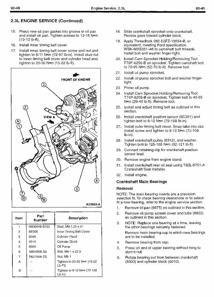
02-49 Engine Service, 2.3L 02-49
2.3L ENGINE SERVICE (Continued)
15. Press new oil pan gasket into groove in oil pan and install oil pan. Tighten screws to 13-16 Nom (1 O-l 2 lb-ft).
16. Install inner timing belt cover.
17. Install inner timing belt cover screw and nut and tighten to 8-11 Nom (72-97 lb-in). Install stud nut to inner timing belt cover and cylinder head and tighten to 20-30 Nom (15-22 lb-ft).
* FRONT OF ENGINE
Q 3
w
A239604
Item Part
Number
N808049-S102
6E005
6049
6010
6600
N804958-S8
N621906-S2
Description
Stud, M8-1.25 x 51
Inner Timing Belt Cover
Cylinder Head
Cylinder Block
Oil Pump
Bolt, M6-1 x 22.5
Nut, M6-1
Tighten to 20-30 Nom (15-22 Lb-R)
Tighten to 8-12 Nom (72-l 08 Lb-In)
18. Slide crankshaft sprocket onto crankshaft. Recess goes toward cylinder block.
19. Apply Threadlock 262 E2FZ-I 9554-B, or equivalent, meeting Ford specification WSK-M2G351 -A6 to camshaft bolt threads. Install bolt and washer finger-tight.
20. Install Cam Sprocket Holding/Removing Tool ’ T79P-6256-B on sprocket. Tighten camshaft bolt to 70-95 Nom (52-70 lb-ft). Remove tool.
21. Install oil pump sprocket.
22. Install oil pump sprocket bolt and washer finger- tight.
23. Prime oil pump.
24. Install Cam Sprocket Holding/Removing Tool T74P-6256-B on sprocket. Tighten bolt to 40-55 Nom (29-40 lb-ft). Remove tool.
25. install and adjust timing belt as outlined in this section.
26. Install crankshaft position sensor (6C351) and tighten bolt to 8-12 Nom (72-108 lb-in).
27. Install outer timing belt cover. Snap tabs into slot. Install screw and tighten to 8-12 Nom (72-l 08 lb-in).
28. Install crankshaft pulley (6312), and washer. Tighten bolt to 125-I 65 Nom (92-121 lb-ft).
29. Connect retaining clip for crankshaft position sensor lead.
30. Remove engine from engine stand.
31. Install crankshaft rear oil seal using T82L-6701 -A Crankshaft Seal Installer.
32. Install engine.
Crankshaft Main Bearings
Removal
NOTE: The main bearing inserts are a precision selective fit. To check bearing clearances or to select- fit a new bearing, refer to the engine service section.
1. Remove oil pan (6675) as outlined in this section.
2. Remove oil pump screen cover and tube (6622) as outlined in this section.
3. NOTE: Replace one bearing at a time, leaving the other bearings securely fastened.
Remove main bearing cap to which new bearings are to be installed.
4. Remove bearing from cap.
5. Press on end of upper bearing without tang to start it out.
6. Rotate bearing out from between crankshaft (6303) and cylinder block (6010).
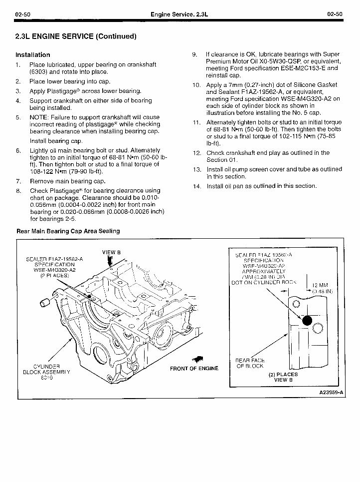
02-50 Engine Service, 2.3L 02-50
2.3L ENGINE SERVICE (Continued)
Installation
1. Place lubricated, upper bearing on crankshaft (6303) and rotate into place.
2. Place lower bearing into cap.
3. Apply Plastigage@ across lower bearing.
4. Support crankshaft on either side of bearing being installed.
5. NOTE: Failure to support crankshaft will cause incorrect reading of plastigage@ while checking bearing clearance when installing bearing cap.
Install bearing cap.
6. Lightly oil main bearing bolt or stud. Alternately tighten to an initial torque of 68-81 Nom (50-60 Ib- ft). Then tighten bolt or stud to a final torque of 108-122 Nom (79-90 lb-ft).
7. Remove main bearing cap.
8. Check Plastigage@ for bearing clearance using chart on package. Clearance should be O.OlO- 0.056mm (0.0004-0.0022 inch) for front main bearing or 0.020-0.066mm (0.0008-0.0026 inch) for bearings 2-5.
Rear Main Bearing Cap Area Sealing
9. If clearance is OK, lubricate bearings with Super Premium Motor Oil X0-5W30-QSP, or equivalent, meeting Ford specification ESE-M2C153-E and reinstall cap.
10. Apply a 7mm (0.27-inch) dot of Silicone Gasket and Sealant Fl AZ-l 9562-A, or equivalent, meeting Ford specification WSE-M4G320-A2 on each side of cylinder block as shown in illustration before installing the No. 5 cap.
11. Alternately tighten bolts or stud to an initial torque of 68-81 Nom (50-60 lb-ft). Then tighten the bolts or stud to a final torque of 102-I 15 Nom (75-85 I b-ft).
12. Check crankshaft end play as outlined in the Section 01.
13. Install oil pump screen cover and tube as outlined in this section.
14. Install oil pan as outlined in this section.
VIEW B SEALER Fl AZ-l 9562-A
SPECIFICATION WSE-M4G320-A2
CYLINDER BLOCK ASSEMBLY
FRONT OF ENG INE
SEALER FlAZ-19562-A SPECIFICATION
WSE-M4G320-A2 APPROXIMATELY 7MM (0.28 IN) DIA.
DOT ON CYLINDER BOCK 12 MM
REAR FACE OF BLOCK
(2) PLACES VIEW B
A23959-A
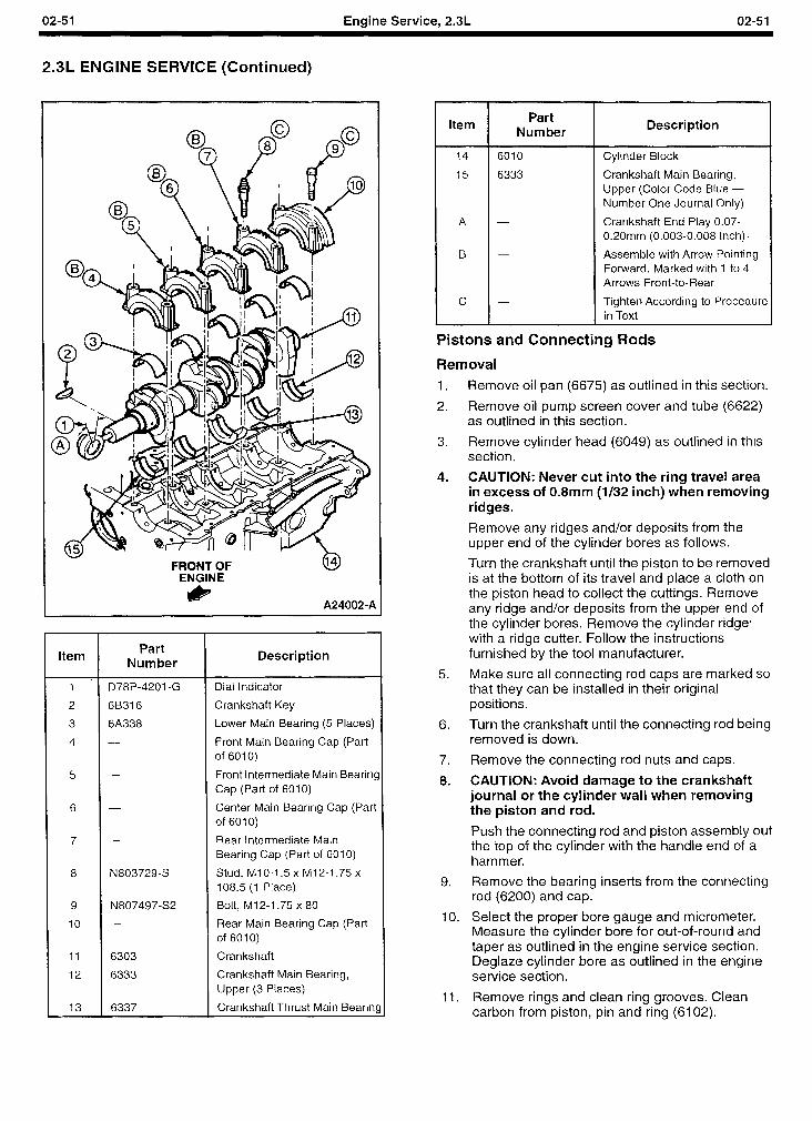
02-51 Engine Service, 2.3L 02-51
2.3L ENGINE SERVICE (Continued)
Item
1 *
2
3
4
D78P-4201 -G
6B316
6A338
5
6 -
7
8 N803729-S
9
10
11
12
13
N80749722
6303
6333
6337
Part Number
Description
Dial Indicator
Crankshaft Key
Lower Main Bearing (5 Places)
Front Main Bearing Cap (Part of 6010)
Front Intermediate Main BearinS Cap (Part of 6010)
Center Main Bearing Cap (Part of 6010)
Rear Intermediate Main Bearing Cap (Part of 6010)
Stud, MIO-1.5 x M12-1.75 x 108.5 (1 Place)
Bolt, M12-1.75 x 80
Rear Main Bearing Cap (Part of 6010)
Crankshaft
Crankshaft Main Bearing, Upper (3 Places)
Crankshaft Thrust Main Beariq
Item Part
Number Description
14 6010 Cylinder Block
15 6333 Crankshaft Main Bearing, Upper (Color Code Blue - Number One Journal Only)
A - Crankshaft End Play 0.07- 0.2Omm (0.003-0.008 Inch) q
B - Assemble with Arrow Pointing Forward. Marked with 1 to 4 Arrows Front-to-Rear
c - Tighten According to Procedure in Text
Pistons and Connecting Rods
1.
2.
3.
4.
5.
6.
7.
8.
9.
10.
11.
Removal
Remove oil pan (6675) as outlined in this section.
Remove oil pump screen cover and tube (6622) as outlined in this section.
Remove cylinder head (6049) as outlined in this section.
CAUTION: Never cut into the ring travel area in excess of 0.8mm (l/32 inch) when removing ridges.
Remove any ridges and/or deposits from the upper end of the cylinder bores as follows.
Turn the crankshaft until the piston to be removed is at the bottom of its travel and place a cloth on the piston head to collect the cuttings. Remove any ridge and/or deposits from the upper end of the cylinder bores. Remove the cylinder ridge4 with a ridge cutter. Follow the instructions furnished by the tool manufacturer.
Make sure all connecting rod caps are marked so that they can be installed in their original positions.
Turn the crankshaft until the connecting rod being removed is down.
Remove the connecting rod nuts and caps.
CAUTION: Avoid damage to the crankshaft journal or the cylinder wall when removing the piston and rod.
Push the connecting rod and piston assembly out the top of the cylinder with the handle end of a hammer.
Remove the bearing inserts from the connecting rod (6200) and cap.
Select the proper bore gauge and micrometer. Measure the cylinder bore for out-of-round and taper as outlined in the engine service section. Deglaze cylinder bore as outlined in the engine service section.
Remove rings and clean ring grooves. Clean carbon from piston, pin and ring (6102).
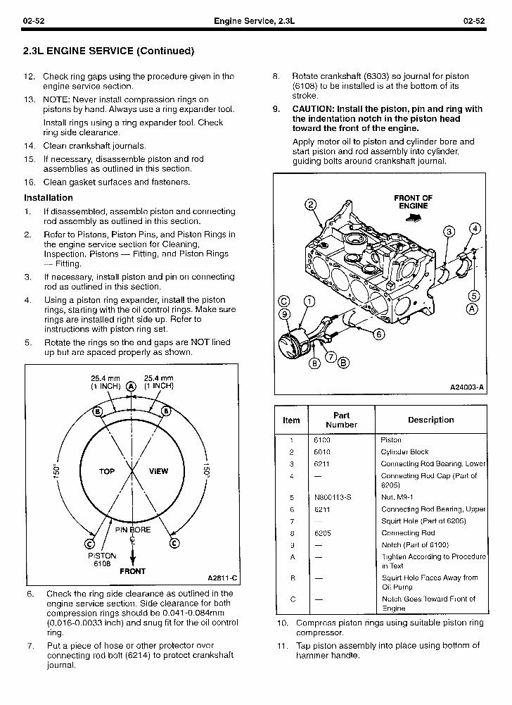
02-52 Engine Service, 2.3L 02-52
2.3L ENGINE SERVICE (Continued)
12. Check ring gaps using the procedure given in the engine service section.
13. NOTE: Never install compression rings on pistons by hand. Always use a ring expander tool.
Install rings using a ring expander tool. Check ring side clearance.
14. Clean crankshaft journals.
15. If necessary, disassemble piston and rod assemblies as outlined in this section.
16. Clean gasket surfaces and fasteners.
installation
1. If disassembled, assemble piston and connecting rod assembly as outlined in this section.
2. Refer to Pistons, Piston Pins, and Piston Rings in the engine service section for Cleaning, Inspection, Pistons - Fitting, and Piston Rings - Fitting.
3. If necessary, install piston and pin on connecting rod as outlined in this section.
4. Using a piston ring expander, install the piston rings, starting with the oil control rings. Make sure rings are installed right side up. Refer to instructions with piston ring set.
5. Rotate the rings so the end gaps are NOT lined up but are spaced properly as shown.
FRONT A281 1 -c
6. Check the ring side clearance as outlined in the engine service section. Side clearance for both compression rings should be 0.041-0.084mm (0.016-0.0033 inch) and snug fit for the oil control rrng.
7. Put a piece of hose or other protector over connecting rod bolt (6214) to protect crankshaft journal.
8. Rotate crankshaft (6303) so journal for piston (6108) to be installed is at the bottom of its stroke.
9. CAUTION: Install the piston, pin and ring with the indentation notch in the piston head toward the front of the engine.
Apply motor oil to piston and cylinder bore and start piston and rod assembly into cylinder, guiding bolts around crankshaft journal.
FRONT OF ENGINE
A24003-A
Item Part
Number Description
1 6100 Piston
2 6010 Cylinder Block
3 6211 Connecting Rod Bearing, Lower
4 - Connecting Rod Cap (Part of 6205)
5 N800113-s Nut, M9-1
6 6211 Connecting Rod Bearing, Upper
7 - Squirt Hole (Part of 6205)
8 6205 Connecting Rod
9 - Notch (Part of 6100)
A - Tighten According to Procedure in Text
B - Squirt Hole Faces Away from Oil Pump
c - Notch Goes Toward Front of Engine
10. Compress piston rings using suitable piston ring compressor.
11. Tap piston assembly into place using bottom of hammer handle.
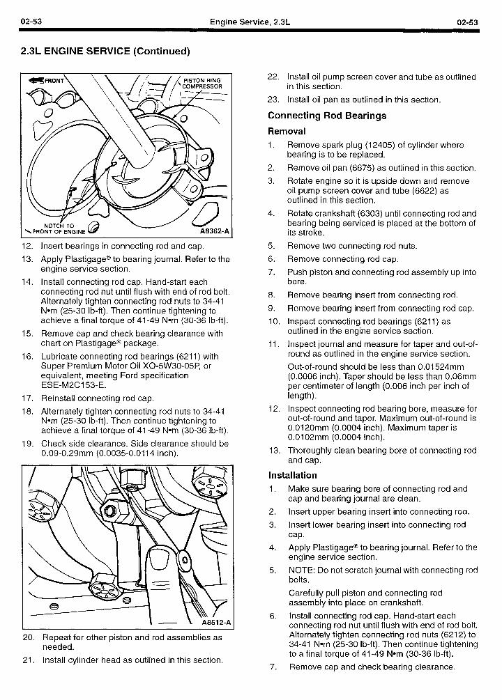
02-53 Engine Service, 2.3L 02-53
2.3L ENGINE SERVICE (Continued)
PISTON RING
12.
13.
14.
15.
16.
17.
18.
19.
Insert bearings in connecting rod and cap.
Apply Plastigage@ to bearing journal. Refer to the engine service section.
Install connecting rod cap. Hand-start each connecting rod nut until flush with end of rod bolt. Alternately tighten connecting rod nuts to 34-41 Nom (25-30 lb-ft). Then continue tightening to achieve a final torque of 41-49 Nom (30-36 lb-ft).
Remove cap and check bearing clearance with chart on Plastigage@ package.
Lubricate connecting rod bearings (6211) with Super Premium Motor Oil X0-5W30-05P, or equivalent, meeting Ford specification ESE-M2C153-E.
Reinstall connecting rod cap.
Alternately tighten connecting rod nuts to 34-41 Nom (25-30 lb-ft). Then continue tightening to achieve a final torque of 41-49 Nom (30-36 lb-ft).
Check side clearance. Side clearance should be 0.09-0.29mm (0.0035-0.0114 inch).
20.
21.
Repeat for other piston and rod assemblies as needed.
Install cylinder head as outlined in this section.
22. Install oil pump screen cover and tube as outlined in this section.
23. Install oil pan as outlined in this section.
Connecting Rod Bearings
Removal
1.
2.
3.
4.
5.
6.
7.
8.
9.
10.
11.
12.
13.
Remove spark plug (12405) of cylinder where bearing is to be replaced.
Remove oil pan (6675) as outlined in this section.
Rotate engine so it is upside down and remove oil pump screen cover and tube (6622) as outlined in this section.
Rotate crankshaft (6303) until connecting rod and bearing being serviced is placed at the bottom of its stroke.
Remove two connecting rod nuts.
Remove connecting rod cap.
Push piston and connecting rod assembly up into bore.
Remove bearing insert from connecting rod.
Remove bearing insert from connecting rod cap.
Inspect connecting rod bearings (6211) as outlined in the engine service section.
Inspect journal and measure for taper and out-of- round as outlined in the engine service section.
Out-of-round should be less than 0.01524mm (0.0006 inch). Taper should be less than 0.06mm per centimeter of length (0.006 inch per inch of length).
Inspect connecting rod bearing bore, measure for out-of-round and taper. Maximum out-of-round is 0.0120mm (0.0004 inch). Maximum taper is 0.0102mm (0.0004 inch).
Thoroughly clean bearing bore of connecting rod and cap.
Installation
1. Make sure bearing bore of connecting rod and cap and bearing journal are clean.
2. Insert upper bearing insert into connecting rod.
3. Insert lower bearing insert into connecting rod cap.
4. Apply Plastigage@ to bearing journal. Refer to the engine service section.
5. NOTE: Do not scratch journal with connecting rod bolts.
Carefully pull piston and connecting rod assembly into place on crankshaft.
6. Install connecting rod cap. Hand-start each connecting rod nut until flush with end of rod bolt. Alternately tighten connecting rod nuts (6212) to 34-41 Nom (25-30 lb-ft). Then continue tightening to a final torque of 41-49 Nom (30-36 lb-ft).
7. Remove cap and check bearing clearance.
02-54 Engine Service, 2.3L 02-54
2.3L ENGINE SERVICE (Continued)
8. Lubricate connecting rod bearings (6211) with Motorcraft Super Premium Motor Oil X0-5W30-QSP, or equivalent, 5W30 motor oil meeting Ford specification ESG-M2C153-E.
9. Install connecting rod cap.
IO. Hand start connecting rod nuts (6212) until nuts are flush with ends of connecting rod bolts.
11. Alternately tighten connecting rod nuts to 34-41 Nom (2530 lb-ft). Then alternately tighten again to a final torque of 41-49 Nom (30-36 lb-ft).
12. Install oil pump screen cover and tube as outlined in this section.
13. Install oil pan as outlined in this section.
14. Install spark plugs.
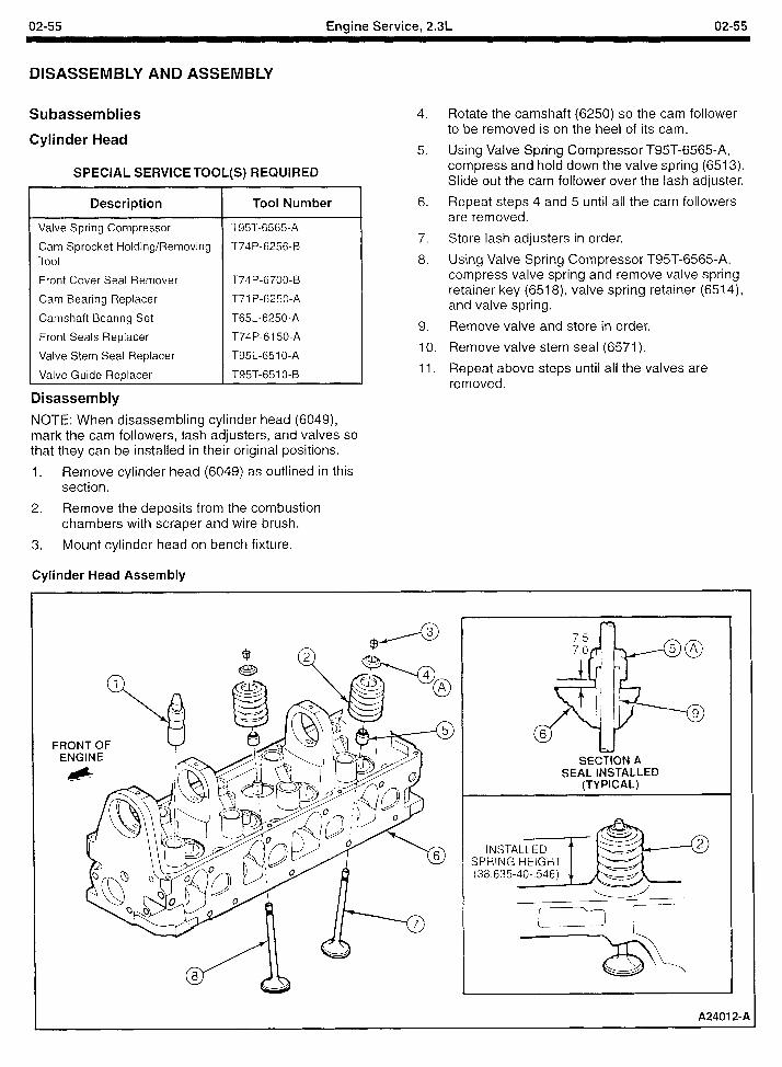
02-55 Engine Service, 2.3L 02-55
DISASSEMBLY AND ASSEMBLY
Subassemblies
Cylinder Head
SPECIAL SERVICE TOOL(S) REQUIRED
Description Tool Number
Valve Spring Compressor T95T-6565-A
Cam Sprocket Holding/Removing T74P-6256-B Tool
Front Cover Seal Remover T74P-6700-B
Cam Bearing Replacer T71 P-6250-A
Camshaft Bearing Set T65L-6250-A
Front Seals Replacer T74P-6 150-A
Valve Stem Seal Replacer T95L-651 O-A
Valve Guide Replacer T95T-651 O-B
Disassembly
NOTE: When disassembling cylinder head (6049), mark the cam followers, lash adjusters, and valves so that they can be installed in their original positions.
1. Remove cylinder head (6049) as outlined in this section.
2. Remove the deposits from the combustion chambers with scraper and wire brush.
3. Mount cylinder head on bench fixture.
Cylinder Head Assembly
4.
5.
6.
7.
8.
9.
IO.
11.
Rotate the camshaft (6250) so the cam follower to be removed is on the heel of its cam.
Using Valve Spring Compressor T95T-6565-A, compress and hold down the valve spring (6513). Slide out the cam follower over the lash adjuster.
Repeat steps 4 and 5 until all the cam followers are removed.
Store lash adjusters in order.
Using Valve Spring Compressor T95T-6565-A, compress valve spring and remove valve spring retainer key (6518) valve spring retainer (6514), and valve spring.
Remove valve and store in order.
Remove valve stem seal (6571).
Repeat above steps until all the valves are removed.
FRONT OF ENGINE SECTION A
SEAL INSTALLED (TYPICAL)
A2401 2-l
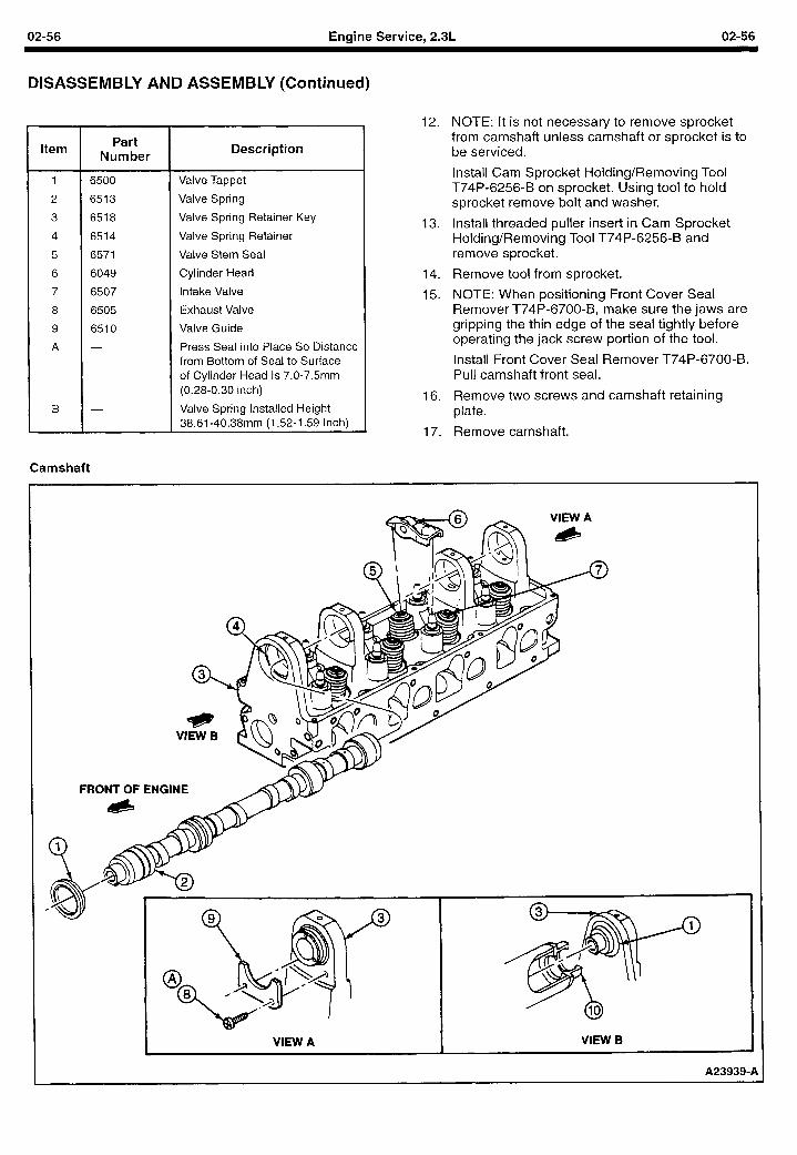
02-56 Engine Service, 2.3L 02-56
DISASSEMBLY AND ASSEMBLY (Continued)
Item Part Number
Description
1 6500 Valve Tappet
2 6513 Valve Spring
3 6518 Valve Spring Retainer Key
4 6514 Valve Spring Retainer
5 6571 Valve Stem Seal
6 6049 Cylinder Head
7 6507 Intake Valve
8 6505 Exhaust Valve
9 6510 Valve Guide
A - Press Seal into Place So Distance from Bottom of Seal to Surface of Cylinder Head Is 7.0-7.5mm (0.28-0.30 inch)
B - Valve Spring Installed Height 38.61-40.38mm (1.52-1.59 Inch)
Camshaft
12. NOTE: It is not necessary to remove sprocket from camshaft unless camshaft or sprocket is to be serviced.
Install Cam Sprocket Holding/Removing Tool T74P-6256-B on sprocket. Using tool to hold sprocket remove bolt and washer.
13. Install threaded puller insert in Cam Sprocket Holding/Removing Tool T74P-6256-B and remove sprocket.
14. Remove tool from sprocket.
15. NOTE: When positioning Front Cover Seal Remover T74P-6700-B, make sure the jaws are gripping the thin edge of the seal tightly before operating the jack screw portion of the tool.
Install Front Cover Seal Remover T74P-6700-B. Pull camshaft front seal.
16. Remove two screws and camshaft retaining plate.
17. Remove camshaft.
FRONT OF ENGINE
A23939-A
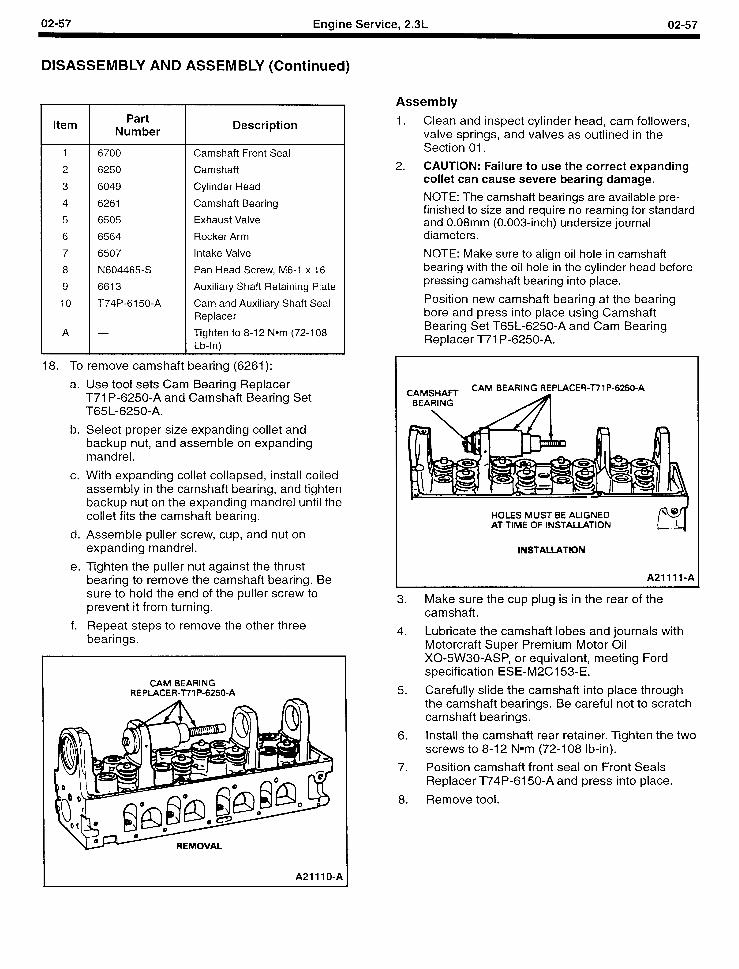
02-57 Engine Service, 2.3L 02-57
DISASSEMBLY AND ASSEMBLY (Continued)
Item
1 6700
2 6250
3 6049
4 6261
5 6505
6 6564
7 6507
8 N604465-S
9 6613
IO T74P-6150-A
A
Part Number T
18. To remove camshaft bearing (6261):
a. Use tool sets Cam Bearing Replacer T71 P-6250-A and Camshaft Bearing Set T65L-6250-A.
b. Select proper size expanding collet and backup nut, and assemble on expanding mandrel.
c. With expanding collet collapsed, install coiled assembly in the camshaft bearing, and tighten backup nut on the expanding mandrel until the collet fits the camshaft bearing.
d. Assemble puller screw, cup, and nut on expanding mandrel.
Description
Camshaft Front Seal
Camshaft
Cylinder Head
Camshaft Bearing
Exhaust Valve
Rocker Arm
Intake Valve
Pan Head Screw, M6-1 x 16
Auxiliary Shaft Retaining Plate
Cam and Auxiliary Shaft Seal Replacer
Tighten to 8-l 2 Nom (72-l 08 Lb-In)
e. Tighten the puller nut against the thrust bearing to remove the camshaft bearing. Be sure to hold the end of the puller screw to prevent it from turning.
f. Repeat steps to remove the other three bearings.
CAM BEARING REPLACER-771P-6250-A
REMOVAL
A21 11 O-A
Assembly
1. Clean and inspect cylinder head, cam followers, valve springs, and valves as outlined in the Section 01.
2. CAUTION: Failure to use the correct expanding collet can cause severe bearing damage.
NOTE: The camshaft bearings are available pre- finished to size and require no reaming for standard and 0.08mm (0.003-inch) undersize journal diameters.
NOTE: Make sure to align oil hole in camshaft bearing with the oil hole in the cylinder head before pressing camshaft bearing into place.
Position new camshaft bearing at the bearing bore and press into place using Camshaft Bearing Set T65L-6250-A and Cam Bearing Replacer T71 P-6250-A.
CAMSHAFT CAM BEARING REPLACER-77 1 P-6250-A
BEARING
HOLES MUST BE ALIGNED AT TIME OF INSTALLATION
INSTALLATION
A21111-A
3. Make sure the cup plug is in the rear of the camshaft.
4. Lubricate the camshaft lobes and journals with Motorcraft Super Premium Motor Oil X0-5W30-ASP, or equivalent, meeting Ford specification ESE-M2C153-E.
5. Carefully slide the camshaft into place through the camshaft bearings. Be careful not to scratch camshaft bearings.
6. Install the camshaft rear retainer. Tighten the two screws to 8-12 Nom (72-l 08 lb-in).
7. Position camshaft front seal on Front Seals Replacer T74P-6150-A and press into place.
8. Remove tool.
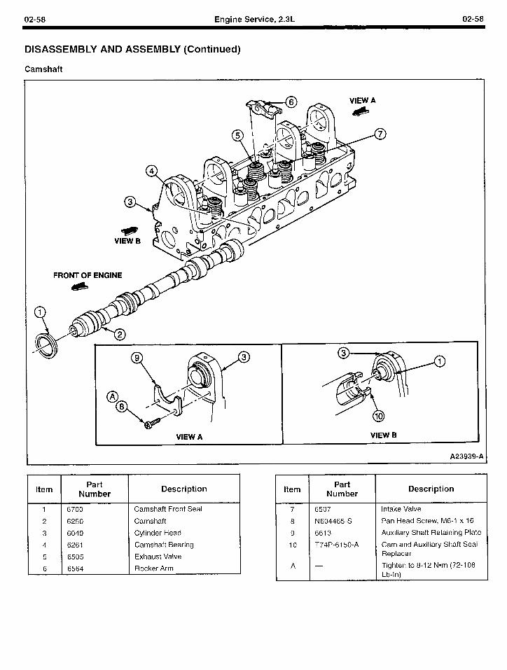
02-58 Engine Service, 2.3L 02-58
DISASSEMBLY AND ASSEMBLY (Continued)
Camshaft
FRONT OF ENGINE
A239394
Item Part
Number
1 6700 Camshaft Front Seal
2 6250 Camshaft
3 6049 Cylinder Head
4 6261 Camshaft Bearing
5 6505 Exhaust Valve
6 6564 Rocker Arm
Description Item
7 6507
8 N604465-5
9 6613
10 T74P-6150-A
A
Part Number
Description
Intake Valve
Pan Head Screw, M6-1 x 16
Auxiliary Shaft Retaining Plate
Cam and Auxiliary Shaft Seal Replacer
Tighten to 8-12 Nom (72-l 08 Lb-In)
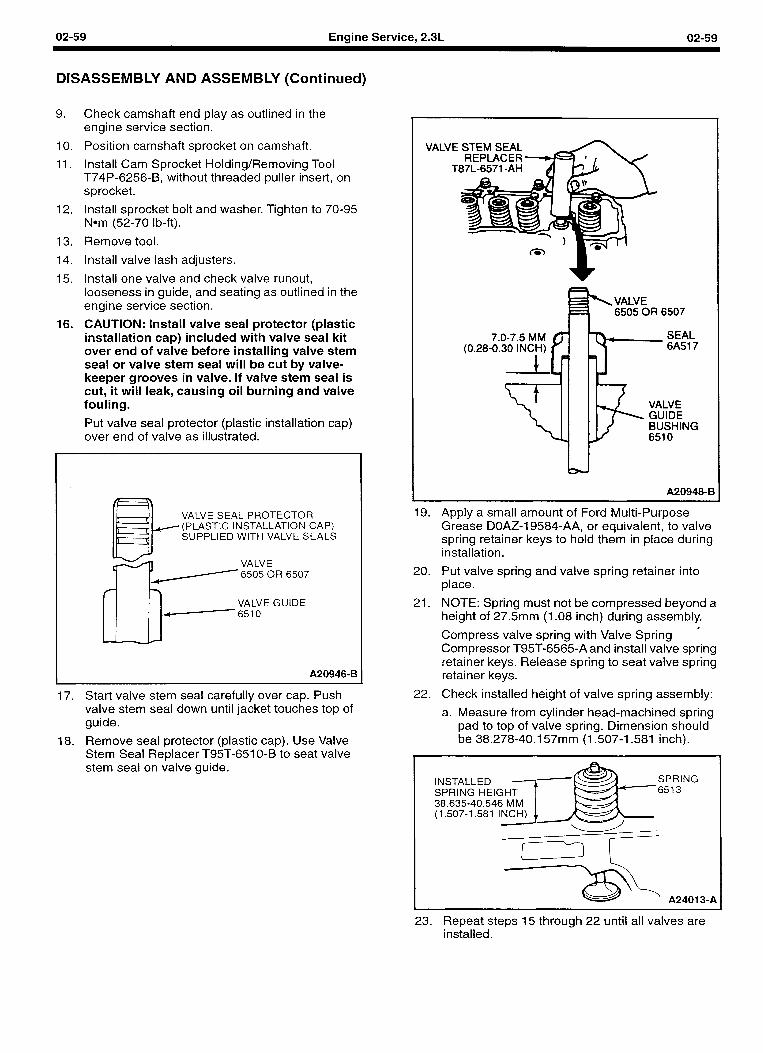
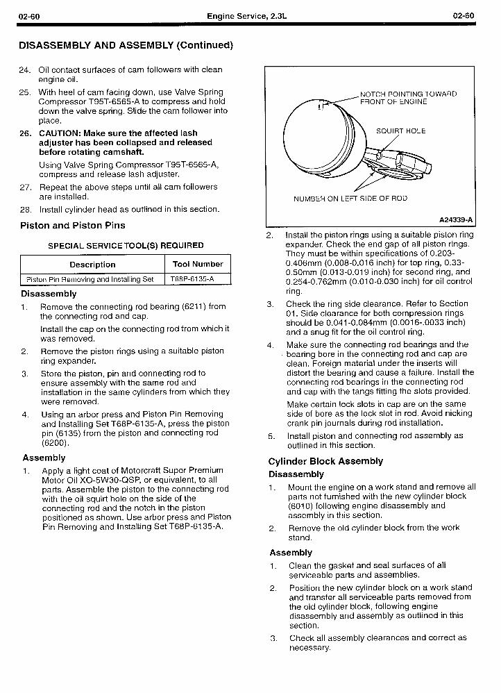
02-60 Engine Service, 2.3L 02-60
DISASSEMBLY AND ASSEMBLY (Continued)
24. Oil contact surfaces of cam followers with clean engine oil.
25. With heel of cam facing down, use Valve Spring Compressor T95T-6565-A to compress and hold down the valve spring. Slide the cam follower into place.
26. CAUTION: Make sure the affected lash adjuster has been collapsed and released before rotating camshaft.
Using Valve Spring Compressor T95T-6565-A, compress and release lash adjuster.
27. Repeat the above steps until all cam followers are installed.
28. Install cylinder head as outlined in this section.
Piston and Piston Pins
SPECIAL SERVICE TOOL(S) REQUIRED
Description Tool Number
Piston Pin Removing and Installing Set T68P-6135-A
Disassembly
1. Remove the connecting rod bearing (6211) from the connecting rod and cap.
Install the cap on the connecting rod from which it was removed.
2. Remove the piston rings using a suitable piston ring expander.
3. Store the piston, pin and connecting rod to ensure assembly with the same rod and installation in the same cylinders from which they were removed.
4. Using an arbor press and Piston Pin Removing and Installing Set T68P-6135-A, press the piston pin (6135) from the piston and connecting rod (6200).
Assembly
1. Apply a light coat of Motorcraft Super Premium Motor Oil X0-5W30-QSP, or equivalent, to all parts. Assemble the piston to the connecting rod with the oil squirt hole on the side of the connecting rod and the notch in the piston positioned as shown. Use arbor press and Piston Pin Removing and Installing Set T68P-6135-A.
-NOTCH POINTING TOWARD FRONT OF ENGINE
NUMBER ON LEFT SIDE OF ROD
A24339-A
2. Install the piston rings using a suitable piston ring expander. Check the end gap of all piston rings. They must be within specifications of 0.203- 0.406mm (0.008-0.016 inch) for top ring, 0.33- 0.50mm (0.013-0.019 inch) for second ring, and 0.254-0.762mm (0.01 O-0.030 inch) for oil control ring.
3. Check the ring side clearance. Refer to Section 01. Side clearance for both compression rings should be 0.041-0.084mm (0.0016-.0033 inch) and a snug fit for the oil control ring.
4. Make sure the connecting rod bearings and the bearing bore in the connecting rod and cap are clean. Foreign material under the inserts will distort the bearing and cause a failure. Install the connecting rod bearings in the connecting rod and cap with the tangs fitting the slots provided.
Make certain lock slots in cap are on the same side of bore as the lock slot in rod. Avoid nicking crank pin journals during rod installation.
5. Install piston and connecting rod assembly as outlined in this section.
Cylinder Block Assembly Disassembly
1. Mount the engine on a work stand and remove all parts not furnished with the new cylinder block (6010) following engine disassembly and assembly in this section.
2. Remove the old cylinder block from the work stand.
Assembly
1. Clean the gasket and seal surfaces of all serviceable parts and assemblies.
2. Position the new cylinder block on a work stand and transfer all serviceable parts removed from the old cylinder block, following engine disassembly and assembly as outlined in this section.
3. Check all assembly clearances and correct as necessary.
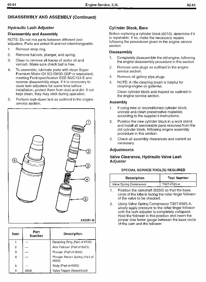
02-61 Engine Service, 2.3L 02-61
DISASSEMBLY AND ASSEMBLY (Continued)
Hydraulic Lash Adjuster
Disassembly and Assembly
NOTE: Do not mix parts between different lash adjusters. Parts are select-fit and not interchangeable.
1. Remove snap ring.
2. Remove fulcrum, plunger, and spring.
3. Clean to remove all traces of motor oil and varnish. Make sure check ball is free.
4. To assemble, lubricate parts with clean Super Premium Motor Oil X0-5W30-QSP or equivalent, meeting Ford specification ESE-M2CI 53-E and reverse disassembly steps. If it is necessary to store lash adjusters for some time before installation, protect them from dust and dirt. If not kept clean, they may stick during operation.
5. Perform leak-down test as outlined in the engine service section.
Cylinder Block, Bare Before replacing a cylinder block (6010), determine if it is repairable. If so, make the necessary repairs following the procedures given in the engine service section.
Disassembly
1. Completely disassemble the old engine, following the engine disassembly procedure in this section.
2. Remove core plugs as outlined in the engine service section.
3. Remove oil gallery pipe plugs.
4. NOTE: A rifle-cleaning brush is helpful for cleaning engine oil galleries.
Clean cylinder block and inspect as outlined in the engine service section.
Assembly
1. If using new or reconditioned cylinder block, uncrate and clean preservative materials according to the supplier’s instructions.
2. Position the new cylinder block in a work stand and install all serviceable parts removed from the old cylinder block, following engine assembly procedure in this section.
Al0081-E
Item Part
Number Description
5
6 6500
2. Using Valve Spring Compressor T95T-6565-A, slowly apply pressure to the roller finger follower until the lash adjuster is completely collapsed. Hold the follower in this position and insert the proper size feeler gauge between the base circle of the cam and the follower.
Retaining Ring (Part of 6500)
Arm Fulcrum (Part of 6500)
Plunger (Part of 6500)
Plunger Return Spring (Part of 6500) Body (Part of 6500)
Valve Tappet (Assembled)
3. Check all assembly clearances and correct as necessary.
Adjustments
Valve Clearance, Hydraulic Valve Lash Adjuster
SPECIAL SERVICE TOOL(S) REQUIRED .
Description Tool Number
Valve Spring Compressor T95T-6565-A
1. Position the camshaft (6250) so that the base, circle of the lobe is facing the roller finger follower of the valve to be checked.
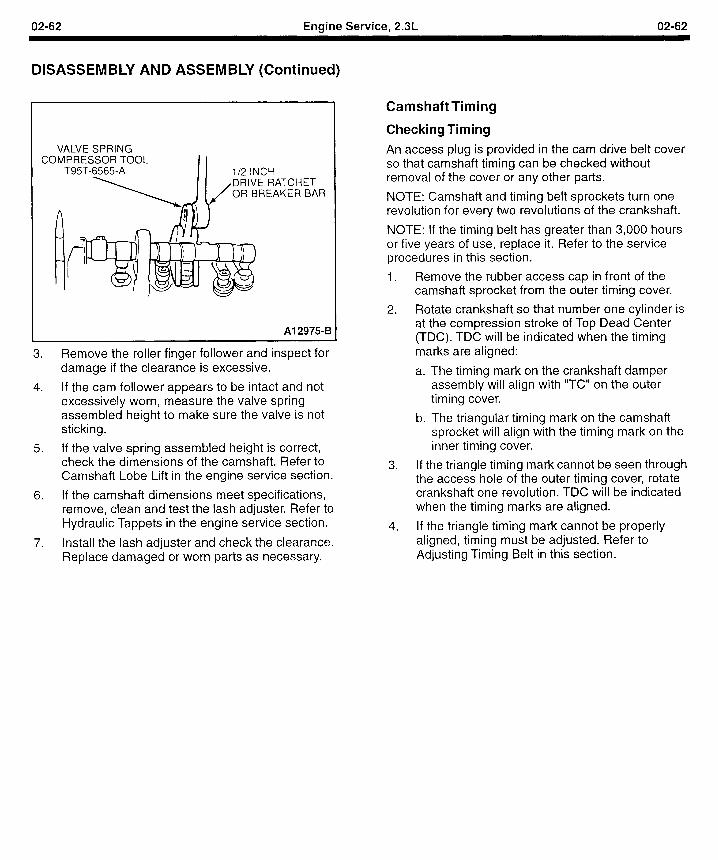
02-62 Engine Service, 2.3L 02-62
DISASSEMBLY AND ASSEMBLY (Continued)
CC VALVE SPRING
IMPRESSOR TOOL T95T-6565-A II l/2 INCH
RAT ‘CHET ;EAK ER BAR
Al 2975-B
3. Remove the roller finger follower and inspect damage if the clearance is excessive.
for
4. If the cam follower appears to be intact and not excessively worn, measure the valve spring assembled height to make sure the valve is not sticking.
5. If the valve spring assembled height is correct, check the dimensions of the camshaft. Refer to Camshaft Lobe Lift in the engine service section.
6. If the camshaft dimensions meet specifications, remove, clean and test the lash adjuster. Refer to Hydraulic Tappets in the engine service section.
7. Install the lash adjuster and check the clearance. Replace damaged or worn parts as necessary.
Camshaft Timing
Checking Timing
An access plug is provided in the cam drive belt cover so that camshaft timing can be checked without removal of the cover or any other parts.
NOTE: Camshaft and timing belt sprockets turn one revolution for every two revolutions of the crankshaft.
NOTE: If the timing belt has greater than 3,000 hours or five years of use, replace it. Refer to the service procedures in this section.
1.
2.
Remove the rubber access cap in front of the camshaft sprocket from the outer timing cover.
Rotate crankshaft so that number one cylinder is at the compression stroke of Top Dead Center (TDC). TDC will be indicated when the timing marks are aligned:
a. The timing mark on the crankshaft damper assembly will align with “TC” on the outer timing cover.
b. The triangular timing mark on the camshaft sprocket will align with the timing mark on the inner timing cover.
If the triangle timing mark cannot be seen through the access hole of the outer timing cover, rotate crankshaft one revolution. TDC will be indicated when the timing marks are aligned.
If the triangle timing mark cannot be properly aligned, timing must be adjusted. Refer to Adjusting Timing Belt in this section.
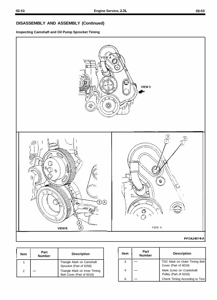
02-63 Engine Service, 2.3L 02-63
DISASSEMBLY AND ASSEMBLY (Continued)
Inspecting Camshaft and Oil Pump Sprocket Timing
VIEW B
&
VIEW B VIEW A.
PPDA24014-A
I IItem PartNumber Description
1 -
2 -
Triangle Mark on CamshaftSprocket (Part of 6256)
Triangle Mark on Inner TimingBelt Cover (Part of 6019)
I IItem PartNumber Description
3 -
4 -
A -
TDC Mark on Outer Timing BeltCover (Part of 6019)
Mark (Line) on CrankshaftPulley (Part of 6316)
Check Timing According to Text
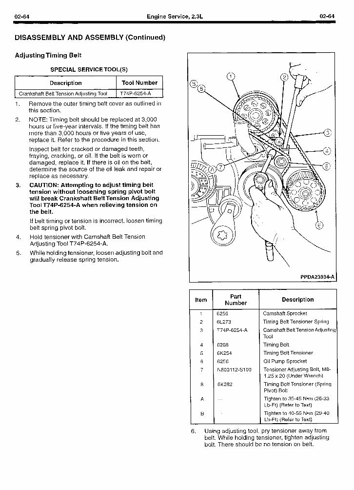
02-64 Engine Service, 2.3L 02-64
DISASSEMBLY AND ASSEMBLY (Continued)
Adjusting Timing Belt
SPECIAL SERVICE TOOL(S)
I Description I Tool Number
I 1 Crankshaft Belt Tension Adjusting Tool 1 T74P-6254-A 1
1.
2.
3.
4.
5.
Remove the outer timing belt cover as outlined in this section.
NOTE: Timing belt should be replaced at 3,000 hours or five-year intervals. If the timing belt has more than 3,000 hours or five years of use, replace it. Refer to the procedure in this section.
Inspect belt for cracked or damaged teeth, fraying, cracking, or oil. If the belt is worn or damaged, replace it. If there is oil on the belt, determine the source of the oil leak and repair or replace as necessary.
CAUTION: Attempting to adjust timing belt tension without loosening spring pivot bolt will break Crankshaft Belt Tension Adjusting Tool T74P-6254-A when relieving tension on the belt.
If belt timing or tension is incorrect, loosen timing belt spring pivot bolt.
Hold tensioner with Camshaft Belt Tension Adjusting Tool T74P-6254-A.
While holding tensioner, loosen adjusting bolt and gradually release spring tension.
PPDA23934-A
Item Part
Number Description
1 6256 Camshaft Sprocket
2 6L273 Timing Belt Tensioner Spring
3 T74P-6254-A Camshaft Belt Tension Adjusting Tool
4 6268 Timing Belt
5 6K254 Timing Belt Tensioner
6 6256 Oil Pump Sprocket
7 N800112-s100 Tensioner Adjusting Bolt, M8- 1.25 x 20 (Under Wrench)
8 6K282 Timing Belt Tensioner (Spring Pivot) Bolt
A - Tighten to 35-45 Nom (26-33 Lb-Ft) (Refer to Text)
B - Tighten to 40-55 Nom (29-40 Lb-Ft) (Refer to Text)
6. Using adjusting tool, pry tensioner away from belt. While holding tensioner, tighten adjusting bolt. There should be no tension on belt.
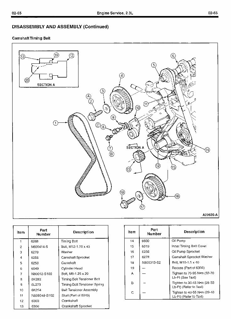
02-65 Engine Service, 2.3L 02-65
DISASSEMBLY AND ASSEMBLY (Continued)
Camshaft Timing Belt
A23935-A
Item
1
2
3
4
5
6
7
8
9
IO
11
12
13
Part Number
Description
6268 Timing Belt
N600414-S Bolt, MIZ-1.75 x 45
6278 Washer
6256 Camshaft Sprocket
6250 Camshaft
6049 Cylinder Head
N8001 z-s1 00 Bolt, M8-1.25 x 20
6K282 Timing Belt Tensioner Bolt
6L273 Timing Belt Tensioner Spring
6K254 Belt Tensioner Assembly
N808049-SIOZ Stud (Part of 6049)
6303 Crankshaft
6306 Crankshaft Sprocket
Item
14
15
16
17
18
19
A
B
C
Part Number
6600
6019
6256
6278
N600313-S2
Description
Oil Pump
Inner Timing Belt Cover
Oil Pump Sprocket
Camshaft Sprocket Washer
Bolt, MIO-1.5 x 40
Recess (Part of 6306)
Tighten to 70-95 Nom (52-70 Lb-Ft (See Text)
Tighten to 35-45 Nom (26-33 Lb-Ft) (Refer to Text)
Tighten to 40-55 Nom (29-40 Lb-Ft) (Refer to Text)
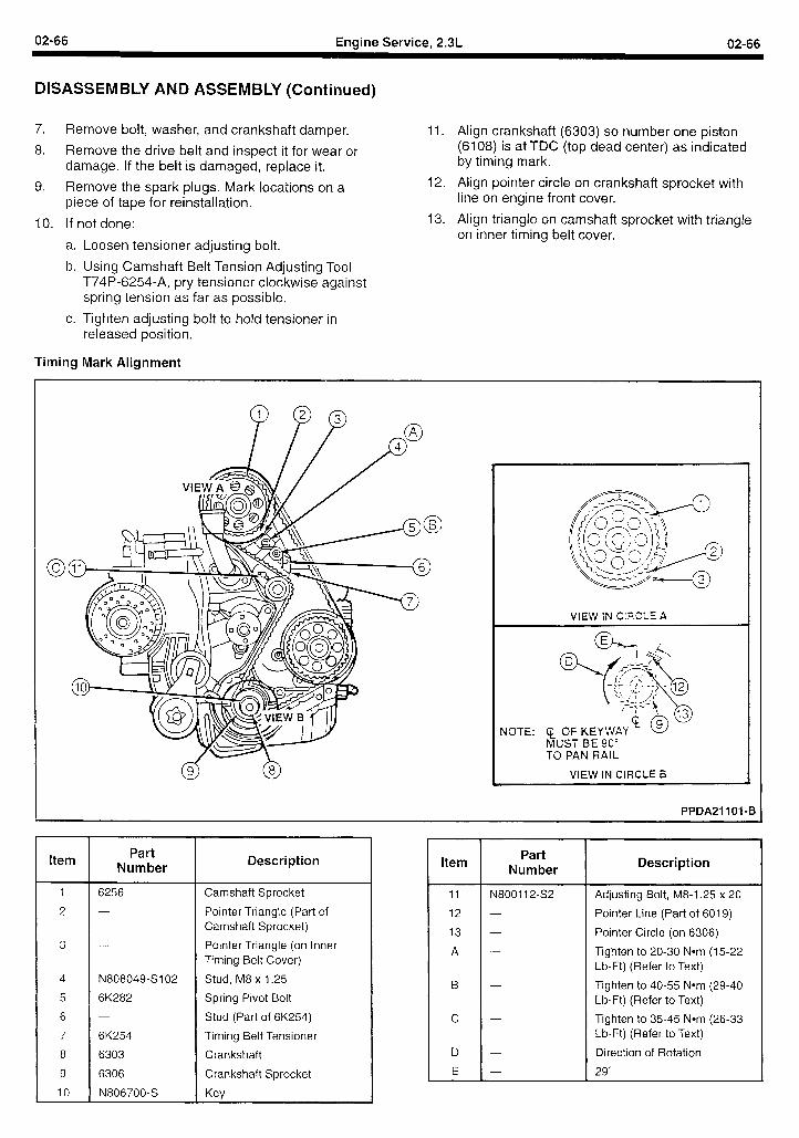
02-66 Engine Service, 2.3L 02-66
DISASSEMBLY AND ASSEMBLY (Continued)
7. Remove bolt, washer, and crankshaft damper. 11. Align crankshaft (6303) so number one piston
8. Remove the drive belt and inspect it for wear or (6108) is at TDC (top dead center) as indicated
damage. If the belt is damaged, replace it. by timing mark.
9. Remove the spark plugs. Mark locations on a 12. Align pointer circle on crankshaft sprocket with
piece of tape for reinstallation. line on engine front cover.
IO. If not done:
a. Loosen tensioner adjusting bolt.
b. Using Camshaft Belt Tension Adjusting Tool T74P-6254-A, pry tensioner clockwise against spring tension as far as possible.
13. Align triangle on camshaft sprocket with triangle on inner timing belt cover.
c. Tighten adjusting bolt to hold tensioner in released position.
Timing Mark Alignment
G C
VIEW IN CIRCLE A 1
NOTE: ($ OF KEYWAY MUST BE 90” TO PAN RAIL
VIEW IN CIRCLE B
PPDA21101-B
Item Part
Number
6256
N808049-S102
6K282
6K254
6303
6306
N806700-S
Description Item
Camshaft Sprocket
Pointer Triangle (Part of Camshaft Sprocket)
Pointer Triangle (on Inner Timing Belt Cover)
Stud, M8 x 1.25
Spring Pivot Bolt
Stud (Part of 6K254)
Timing Belt Tensioner
Crankshaft
Crankshaft Sprocket
Key
II
12
13
A
B
C
D
E
Part Number
-N800112-S2
Description
Adjusting Bolt, M8-1.25 x 20
Pointer Line (Part of 6019)
Pointer Circle (on 6306)
Tighten to 20-30 Nom (15-22 Lb-Ft) (Refer to Text)
Tighten to 40-55 Nom (29-40 Lb-Ft) (Refer to Text)
Tighten to 35-45 Nom (26-33 Lb-Ft) (Refer to Text)
Direction of Rotation
29”
02-67 Engine Service, 2.3L 02-67
DISASSEMBLY AND ASSEMBLY (Continued)
14.
15.
16.
17.
Install timing belt over crankshaft sprocket(6306). Then, proceeding counterclockwise, overoil pump sprocket and camshaft sprocket, verifytiming marks are aligned.
Loosen tensioner adjusting bolt allowingtensioner pulley to press against timing be It.
NOTE: When performing the following step, donot rotate crankshaft counterclockwise as timingbelt may jump a cog, putting camshaft out oftime.
Rotate crankshaft two revolutions clockwise.
Bring crankshaft slowly, without stopping, tonumber one cylinder firing position (keywaydirectly up).
18. Recheck timing mark alignment. Repeat theabove steps if timing marks are no longerproperly aligned.
19. Rotate tensioner assembly against bolt withtorque wrench up to 40-45 Nom (29-33 lb-ft) andtighten adjusting bolt.
20. Tighten adjusting bolt to 35-45 Nom (26-33 lb-ft).
21. Tighten spring pivot bolt to 40-55 Nom (29-40lb-ft).
22. Install outer timing belt cover as outlined in thissection.
23. Install spark plugs in proper locations.
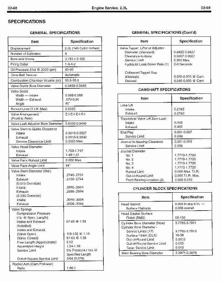
02-68 Engine Service, 2.3L 02-68
SPECIFICATIONS
GENERAL SPECIFICATIONS GENERAL SPECIFICATIONS (Cont’d)
Item Specification
Displacement 2.3L (140 Cubic Inches)
Number of Cylinders 4
Bore and Stroke 3.780 x 3.126
Firing Order 1-3-4-2
Oil Pressure (Hot @ 2000 rpm) 40-60
Drive Belt Tension Automatic
Combustion Chamber Volume (cc) 55.5-58.5
Valve Guide Bore Diameter 0.3433-0.3443
Valve Seats Width - Intake 0.068-0.088 Width - Exhaust .070-0.90 Angle 45”
Runout Limit (T.I.R. Max) 0.0020
Valve Arrangement E-I-E-I-E-I-E-I (Front to Rear)
Valve Lash Adjuster Bore Diameter 0.8430-0.8449
Valve Stem to Guide Clearance Intake 0.001 O-0.0027 Exhaust 0.0015-0.0032 Service Clearance Limit 0.0055 Max.
Valve Head Diameter Intake 1.723-1.747 Exhaust 1.49-1.51
Valve Face Runout Limit 0.002 Max.
Valve Face Angle Limit 44”
Valve Stem Diameter (Std.) Intake .2746-.2754 Exhaust .2736-.2744 (0.015 Oversize) Intake .2896-.2904 Exhaust .2886-.2894 (0.030 Oversize) Intake .3046-.3054 Exhaust .3036-.3044
Valve Springs Compression Pressure (Lb. @ Spec. Length) Intake and Exhaust 57-63 @ 1.56 (Installed) Intake and Exhaust (Valve Open) 118-132 @ 1.16 (Valve Closed) 57-63 @ 1.56 Free Length (Approximate) 2.02 Assembled Height 1.54-1.58 Service Limit 5% Pressure Loss @
Specified Length Out-of-Square Service Limit 5/64 (0.078)
Rocker Arm (Cam Follower) Ratio I .86:l
Item I Specification I Valve Tappet, Lifter or Adjuster
Diameter (Standard) Clearance-to-Bore Service Limit Hydraulic Leak-Down Rate (1)
Collapsed Tappet Gap Allowable
I Desired
0.8422-0.8427 0.0007-0.0027 0.005 Max. 2-8 Seconds
0.035-0.055 @I Cam 0.040-0.050 @ Cam
CAMSHAFT SPECIFICATIONS
Item
Lobe Lift Intake Exhaust
Theoretical Valve Lift Zero Lash Intake Exhaust
End Play Service Limit
Journal-to-Bearing Clearance Service Limit
Journal Diameter No. 1 No. 2 No. 3 No. 4 Runout Limit Out-of-Round Limit Front Bearing Location (2)
Specification
0.2163 0.2163
0.402 0.402
0.001-0.007 0.009
0.001-0.003 0.006
1.7713-l .7720 1.7713-l .7720 1.7713-1.7720 1.7713-I .7720 0.005 Max. T.I.R. 0.005 T.I.R. Max. 0.000-0.010
CYLINDER BLOCK SPECIFICATIONS
Item
Head Gasket Surface Flatness
Head Gasket Surface Finish (RMS)
Cylinder Bore Diameter (New) Cylinder Bore Diameter -
Service Limits (17) Surface Finish (CLA) Out-of-Round Limit Out-of-Round Service Limit Taper Service Limit
Main Bearing Bore Diameter
Specification
0.003 in any 6 In. - 0.006 overall
60-l 50
3.7795-3.7801
3.7793-3.7813 18-38 0.0015 0.005 0.010
2.3971-2.3979
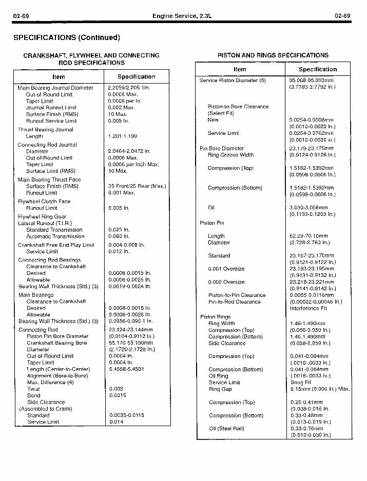
02-69 Engine Service, 2.3L 02-69
SPECIFICATIONS (Continued)
CRANKSHAFT, FLYWHEEL AND CONNECTING ROD SPECIFICATIONS
Item Specification
Main Bearing Journal Diameter 2.2059/2.205 1 In. Out-of-Round Limit 0.0006 Max. Taper Limit 0.0006 per In. Journal Runout Limit 0.002 Max. Surface Finish (RMS) IO Max. Runout Service Limit 0.005 In.
Thrust Bearing Journal Length 1.201-I .I 99
Connecting Rod Journal Diameter 2.0464-2.0472 In. Out-of-Round Limit 0.0006 Max. Taper Limit 0.0006 per Inch Max. Surface Limit (RMS) 10 Max.
Main Bearing Thrust Face Surface Finish (RMS) 35 Front/25 Rear (Max.) Runout Limit 0.001 Max.
Flywheel Clutch Face Runout Limit 0.005 In.
Flywheel Ring Gear Lateral Runout (T.I.R.)
Standard Transmission 0.025 In. Automatic Transmission 0.060 In.
Crankshaft Free End Play Limit 0.004-0.008 In. Service Limit 0.012 In.
Connecting Rod Bearings Clearance to Crankshaft Desired 0.0008-0.0015 In. Allowable 0.0008-0.0026 In.
Bearing Wall Thickness (Std.) (3) 0.061 g-0.0624 In.
Main Bearings Clearance to Crankshaft Desired 0.0008-0.0015 In. Allowable 0.0008-0.0026 In.
Bearing Wall Thickness (Std.) (3) 0.0956-0.095 1 In.
Connecting Rod 23.124-23.144mm Piston Pin Bore Diameter (0.9104-0.9112 In.) Crankshaft Bearing Bore 55.170-55.190mm Diameter (2.1720-2.1728 In.) Out-of-Round Limit 0.0004 In. Taper Limit 0.0004 In. Length (Center-to-Center) 5.4558-5.4591 Alignment (Bore-to-Bore) Max. Difference (4) Twist 0.003 Bend 0.0015 Side Clearance
(Assembled to Crank) Standard 0.0035-0.0115 Service Limit 0.014
PISTON AND RINGS SPECIFICATIONS
Item
Service Piston Diameter (5)
Specification
95.968-95.993mm (3.7783-3.7792 In.)
Piston-to-Bore Clearance (Select Fit) New
Service Limit
Pin Bore Diameter Ring Groove Width
Compression (Top)
0.0254-0.0508mm (0.001 O-0.0020 In.) 0.0254-0.0762mm (0.001 O-0.0030 in.)
23.179-23.175mm (0.9124-0.9126 In.)
1.5182-l .5392mm (0.0598-0.0606 In.)
Compression (Bottom) 1.5182-1.5392mm (0.0598-0.0606 In.)
Oil
Piston Pin
3.030-3.056mm (0.1193-0.1203 In.)
Length Diameter
62.29-70.1 Omm (2.728-2.760 In.)
Standard
0.001 Oversize
0.002 Oversize
Piston-to-Pin Clearance Pin-to-Rod Clearance
23.167-23-l 70mm (0.9121-0.9122 In.) 23.193-23.195mm (0.9131-0.9132 In.) 23.218-23.221 mm (0.9141-0.9142 In.) 0.0055-0.0116mm (0.00022-0.00046 In.) Interference Fit
Piston Rings Ring Width Compression (Top) Compression (Bottom) Side Clearance
1.46-1.490mm (0.058-0.059 In.) 1.46-I .490mm (0.058-0.059 In.)
Compression (Top)
Compression (Bottom) Oil Ring Service Limit Ring Gap
0.041-0.084mm (.0016-.0033 In.) 0.041-0.084mm (.0016-.0033 In.) Snug Fit 0.15mm (0.006 In.) Max.
Compression (Top)
Compression (Bottom)
Oil (Steel Rail)
0.20-0.41 mm (0.008-0.016 In. 0.33-0.48mm (0.013-0.0-l 9 In.) 0.33-0.76mm (0.01 O-0.030 In.)
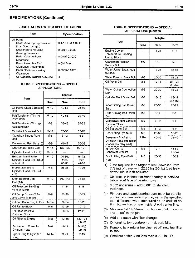
02-70 Engine Service, 2.3L 02-70
SPECIFICATIONS (Continued)
LUBRICATION SYSTEM SPECIFICATIONS
Item
Oil Pump Relief Valve Spring Tension (Lbs. Spec. Length) Driveshaft-to-Housing Bearing Clearance Relief Valve-to-Bore Clearance Rotor Assembly End Clearance (Assembled) Outer Race-to-Housing Clearance Oil Capacity (Quarts U.S.) (6)
Specification
8.4-10.6 @I 1.32 In.
0.0014-0.0033
0.0015-0.0030
0.004 Max.
0.0055-0.0125
4
TORQUE SPECIFICATIONS - SPECIAL APPLICATIONS
Item
Oil Pump Shaft Sprocket M-10
I I
40-55
I
28-40 Bolt I
Belt Tensioner (Timing M-10 Pivot Bolt) I I 40-55 I 29-40
Belt Tensioner (Timing) M-8 I I 35-45 26-33 Adjusting Bolt I
1 Camshaft Sprocket Bolt 1 M-12 1 70-95 1 52-70 I
Camshaft Thrust Plate M-6 Bolt I I 8-12 I 6-9 I
1 Connecting Rod Nut (1 O)l M-9 1 41-49 1 30-36 I
I Crankshaft Pulley Bolt I M-14 I 125-165 I 92-121 1
I Cylinder Head Bolt (I I) I M-12 I - I - I
Exhaust Manifold to Cylinder Head Bolt, Stud or Nut (12)
I- M-IO-1 -ii; I-;;]
Intake Manifold to Cylinder Head Bolt/Nut
(13)
1 M-8 1 26-38 1 19-28 /
I Main Bearing Cap M-12 I I 102-l 15 I 75-85 Bolt (14) I
I Oil Pressure Sending -
I I
11-24
I
8-18 Wire to Block I I Oil Pump Screen Tube M-8
and Cover to Block I I 20-30 I 15-22 I I Oil Pan Drain Plug to Pad M-14 I 20-34 1 15-25 1
I Oil Pan to Block 1 M-6 [ 13-16 1 lo-12 1
I Oil Filter Insert to Cylinder Block I - I 28-35 I 21-26
Oil Filter to Engine (15) I I 13-15 I 120-132 (Lb-In) I
I Rocker Arm Cover to M-6 I I 9-13 Cylinder Head I 84-120
(Lb-In) I Spark Plug to Cylinder M-14 Head I I
TORQUE SPECIFICATIONS - SPECIAL APPLICATIONS (Cont’d)
,
Torque Item
Size Nom Lb-Ft
Engine Coolant 11-24 8-18 Temperature Sending Unit to Block
Crankshaft Position M6 8-12 6-9 Sensor Bolt
Water Jacket Drain Plug - 16-24 12-18 to Block
Water Pump to Block Bolt M-8 20-30 15-22
Oil Pump Bolt M-6 10-14 88-124 (Lb-In)
Water Outlet Connection M-8 20-30 15-22 Bolt
Cylinder Front Cover Bolt M-6 13-16 115-141 (Lb-In)
Inner Timing Belt Cover M-8 20-30 15-22 Stud
Outer Timing Belt Cover M-6 8-12 6-9 Bolt
Crankcase Vent Baffle to M6 8-12 6-9 Cylinder Block
Oil Separator Bolt M6 8-12 6-9
Rear Lifting Eye Nuts M8 20-30 15-22
Generator Bracket to Ml0 40-55 29-40 Cylinder Head and Block (Sequence Required)
Ignition Coil to M5 5-7 44-62 Generator Bracket (Lb-In)
Front Lifting Eye (Bolt/ M8 20-30 15-22 Nut)
(1) Time required for plunger to leak down 3.18mm (l/8 in.) of travel with 22.65 kg (50 lb.) load leak- down fluid in lash adjuster.
(2) Distance in inches that front bearing is installed below front face of bearing tower.
(3) 0.002 undersize = add 0.001 to standard thickness.
(4) Pin bore and crank bearing bore must be parallel and in the same vertical plane, within the specified total difference when measured at the ends of an 8 in. bar - 4 in. on each side of rod center line.
(5) Measured at 14.58mm from bottom of skirt, center line - 90” to the pin.
(6) Add one quart with filter change.
(7) On engine, temperature normal, curb idle.
(8) Pump to tank return line pinched off, new fuel filter in line.
(9) Smallest orifice = no less than 0.220 in. I.D.
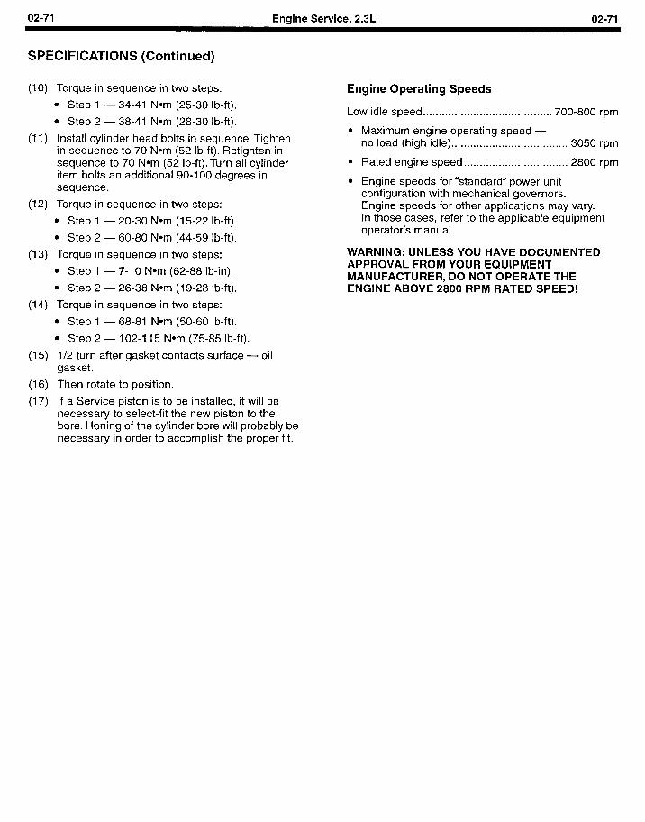
02-71 Engine Service, 2.3L 02-71
SPECIFICATIONS (Continued)
(IO) Torque in sequence in two steps:
l Step 1 - 34-41 Nom (25-30 I b-ft).
l Step 2 - 38-41 Nom (28-30 lb-ft).
(1 I) Install cylinder head bolts in sequence. Tighten in sequence to 70 Nom (52 lb-ft). Retighten in sequence to 70 Nom (52 lb-ft).Turn all cylinder item bolts an additional 90-I 00 degrees in sequence.
(12) Torque in sequence in two steps:
l Step 1 - 20-30 Nom (15-22 lb-ft).
l Step 2- 60-80 Nom (44-59 lb-ft).
(13) Torque in sequence in two steps:
l Step 1 - 7-10 Nom (62-88 lb-in).
l Step 2- 26-38 Nom (19-28 lb-ft).
(14) Torque in sequence in two steps:
l Step 1 - 68-81 Nom (50-60 lb-ft).
l Step 2- 102-1 15 Nom (75-85 lb-ft).
(15) l/2 turn after gasket contacts surface - oil gasket.
(16) Then rotate to position.
(17) If a Service piston is to be installed, it will be necessary to select-fit the new piston to the bore. Honing of the cylinder bore will probably be necessary in order to accomplish the proper fit.
Engine Operating Speeds
Low idle speed . . . . . . . . . . . . . . . . . . . . . . . . . . . . . . . . . . . . . . . . . 700-800 rpm
l Maximum engine operating speed - no load (high idle) . . . . . . . . . . . . . . . . . . . . . . . . . . . . . . . . . . . . . 3050 rpm
l Rated engine speed . . . . . . . . . . . . . . . . . . . . . . . . . . . . . . . . . 2800 rpm
l Engine speeds for “standard” power unit configuration with mechanical governors. Engine speeds for other applications may vary. In those cases, refer to the applicable equipment operator’s manual.
WARNING: UNLESS YOU HAVE DOCUMENTED APPROVAL FROM YOUR EQUIPMENT MANUFACTURER, DO NOT OPERATE THE ENGINE ABOVE 2800 RPM RATED SPEED!
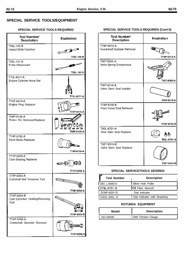
02-72 Engine Service, 2.3L 02-72
SPECIAL SERVICE TOOLS/EQUIPMENT
SPECIAL SERVICE TOOLS REQUIRED SPECIAL SERVICE TOOLS REQUIRED (Cont’d)
Engine Plug Replacer
‘iston Pin Remover/Replacer
T74P-6254-ACamshaft Belt Tensioner Tool
t Holding/Removing
T74P-6306-ACrankshaft Sprocket Remover
Valve Stem Seal Installer
Rear Main Seal Replacer
Valve Stem Seal Replacer
SPECIAL SERVICETOOLS DESIRED
r Tool Number I Description I1 D81 L-6500-A 1 Blind Hole Puller
1 D79L-6731 -B I Oil Filter Wrench
-4201 -G I Dial Indicator I1 TOOL-4201 -C I Dial Indicator with Bracketry I
ROTUNDA EQUIPMENT
Model Description
1 021-00045 I Belt Tension Gauge
03-I Auxiliary Systems 03-I
SECTION TITLE PAGE
ENGINE SERVICE ................................................................ 01-l ENGINE SERVICE, 2.3L ....................................................... 02-l
SECTION TITLE PAGE
AUXILIARY SYSTEMS ......................................................... 03-l
Section 03 - Auxiliary Systems
SUBJECT PAGE SUBJECT PAGE
DISTRIBUTORLESS IGNITION SYSTEM DESCRIPTION AND OPERATION
Warning ............................................................................... 3 Description ......................................................................... 3 Operation ............................................................................ 3 Inputs Affecting Ignition .................................................... 4
Engine Speed and Crankshaft Position .................... .4 Engine Load .................................................................. 4 Engine Temperature ..................................................... 4 Fuel Octane Level Adjustment .................................... 4 UESC Module Outputs ................................................. 4 Sensor Fail-safe ............................................................ 4 Cranking Mode .............................................................. 4 Run Mode ...................................................................... 4 Transient Mode ............................................................. 5 Overspeed Mode ........................................................... 5
Service Adjustments And Checks .................................... 5 DISTRIBUTORLESS IGNITION SYSTEM
DIAGNOSING AND TESTING Diagnosis Equipment ........................................................ 6 Diagnosing ......................................................................... 6
DISTRIBUTORLESS IGNITION SYSTEM REMOVAL AND INSTALLATION
Ignition Coil ...................................................................... 10 Removal ....................................................................... 10 Installation ................................................................... 10
Engine Speed (Crankshaft Position) Sensor ................. 10 Removal ....................................................................... 10 Installation ................................................................... 10
Engine Coolant Temperature Sensor ............................. 11 Removal ....................................................................... 11 Installation ................................................................... 11
Ignition System ................................................................ 12 Crankshaft Position Sensor ...................................... 12
Removal ................................................................... 12 Installation ............................................................... 13
Ignition Coil Pack ....................................................... 14 Removal ................................................................... 14 Installation ............................................................... 15
Ignition Wires .............................................................. 15 Removal ................................................................... 15 Installation ............................................................... 15
Spark Plugs ................................................................. 15 Removal and Installation ....................................... 15
DISTRIBUTORLESS IGNITION SYSTEM CLEANING AND INSPECTION
Spark Plugs ............................................................. 16 Ignition Coil ............................................................. 16 Ignition Wires .......................................................... 16
DISTRIBUTORLESS IGNITION SYSTEM ADJUSTMENTS AND SPECIFICATIONS
Ignition Adjustments .................................................. 17 Spark Plugs ............................................................. 17 Ignition Timing ........................................................ 17
Ignition Specifications ............................................... 17 Ignition Special Service Tools/Equipment ............... 17
FUEL SYSTEM DESCRIPTION AND OPERATION Carburetor Identification ........................................... 18
Electric Fuel Pump .......................................................... 18 FUEL SYSTEM DIAGNOSING AND TESTING
Electrical ........................................................................... 19 Fuel Supply and Pressure ............................................... 19
FUEL PUMP SERVICE AND MAINTENANCE ....................... 20 FUEL PUMP SPECIFICATIONS .............................................. 21 CARBURETOR DIAGNOSIS
General Information ......................................................... 22 Percolation ....................................................................... 22 Flooding ............................................................................ 22 Hard Starting .................................................................... 22 Stalling .............................................................................. 22 Rough Idle ........................................................................ 22 Surging Above Idle .......................................................... 22 Poor Acceleration ............................................................ 22 Leaking Carburetor .......................................................... 23 Inconsistent Idle Speed ................................................... 23 Reduced Power Output ................................................... 23
ZENITH MODEL #33 CARBURETOR OPERATION AND SERVICE
Fuel Supply System ................................................... 24 Idle System ................................................................. 24 High Speed System .................................................... 26 Accelerating Pump System ....................................... 28
Disassembly ..................................................................... 32 Cleaning and Inspection ................................................. 32 Assembly Of Air Intake .................................................... 32 Assembly Of Fuel Bowl ................................................... 32
HOLLEY ONE-BARREL CARBURETOR MODEL 1940 Carburetor Description .................................................... 34 Carburetor Systems ......................................................... 34
Fuel Inlet System ........................................................ 34 Idle Fuel System ......................................................... 34 Main Metering System ............................................... 35 Power Fuel System .................................................... 35 Accelerator Pump System ......................................... 35
Adjustments ..................................................................... 36 Float Adjustment ........................................................ 36 Pump Piston Stroke Adjustment .............................. 36 Idle Speed Adjustment ............................................... 36 Idle Mixture Adjustment ............................................. 37 Fast Idle Adjustment .................................................. 37
Carburetor ........................................................................ 37 Removal ...................................................................... 37 Installation .................................................................. 37
Disassembly and Assembly ............................................ 37 Disassembly ............................................................... 37 Carburetor Body Disassembly .................................. 39 Cleaning ...................................................................... 39 Assembly .................................................................... 39 Adjustments During Assembly ................................. 40
03-2 Auxiliary Systems 03-2
Section 03 - Auxiliary Systems
SUBJECT PAGE SUBJECT PAGE
STARTER, PERMANENT MAGNET DESCRIPTION AND OPERATION
Sequence Of Operation .................................................... 43 Road Service ..................................................................... 44 Jump Starting ................................................................... 44
Negative Grounded Battery ........................................ 44 STARTER, PERMANENT MAGNET DIAGNOSIS
AND TESTING System Inspection ............................................................ 45
Evaluation Procedure 1 .............................................. 46 Evaluation Procedure 2 ............................................... 46 Starter Load Test ......................................................... 46
Bench Tests ....................................................................... 47 Starter No-load Test .................................................... 47 Armature Open Circuit Test ....................................... 48 Grounded Armature Test ............................................ 48 Starter Solenoid Test .................................................. 48
STARTER, PERMANENT MAGNET REMOVAL AND INSTALLATION
Starter Motor ..................................................................... 49 Removal ....................................................................... 49 installation ................................................................... 49 Wiring ........................................................................... 49
STARTER, PERMANENT MAGNET DISASSEMBLY AND ASSEMBLY
Disassembly ................................................................ 51 Cleaning and Inspection ............................................. 51 Assembly ..................................................................... 52
Starter Drive Replacement .............................................. 53 Armature Replacement .................................................... 53
STARTER, PERMANENT MAGNET SPECIFICATIONS.. ..... ..5 4 SPECIAL SERVICE TOOLS ..................................................... 55
GOVERNORS, MECHANICAL DESCRIPTION AND OPERATION ................................................................. 56
GOVERNORS, ADJUSTMENTS Preliminary Checks .......................................................... 57 Oil Level ............................................................................. 57 Belt Tension ....................................................................... 57 Throttle Control Rod ......................................................... 57
GOVERNORS, RPM ADJUSTMENTS High Speed ........................................................................ 58 Sensitivity or “Droop” ...................................................... 58 Increase Droop ................................................................. 59 Decrease Droop ................................................................ 59 Low Speed Idle ................................................................. 59 No-load Surge ................................................................... 59
GOVERNORS, REMOVAL AND INSTALLATION Removal ............................................................................. 60 Installation ......................................................................... 60
GOVERNORS, ELECTRONIC DESCRIPTION AND OPERATION ................................................................. 61
GOVERNORS, ELECTRONIC DIAGNOSING AND TESTING ................................................................................ 62
Calibration ......................................................................... 63
COOLING SYSTEM, DESCRIPTION AND OPERATION ................................................................ 65
COOLING SYSTEM, DIAGNOSING ANDTESTING Diagnosis ........................................................................... 66 General Test Procedures .................................................. 66
Visual Inspection ......................................................... 66 Cooling System Pressure Test ........................................ 66 Radiator Cap Pressure Test ............................................. 67 Thermostat Test -Thermostat Removed ..................... .66
COOLING SYSTEM, REMOVAL AND INSTALLATION Cooling Fan ....................................................................... 69
Removal ....................................................................... 69 Installation ................................................................... 69
Fan Drive Belt .................................................................... 69 Removal ....................................................................... 69 Installation ................................................................... 69
Radiator Hose ................................................................... 69 Removal ....................................................................... 69 Installation ................................................................... 69
Thermostat ........................................................................ 69 Removal ....................................................................... 69 Installation ................................................................... 69
COOLING SYSTEM, CLEANING AND INSPECTION Cleaning Cooling System ................................................ 70
GENERATOR, INTEGRAL REAR MOUNT REGULATOR, INTERNAL FAN TYPE DESCRIPTION AND OPERATION .......................................................................... 71
Generator .......................................................................... 71 Circuit Description ............................................................ 71
Battery Positive Voltage (B+) Output ....................... .71 I Circuit ......................................................................... 71 A Circuit ....................................................................... 71 S Circuit ....................................................................... 71
Visual Inspection .............................................................. 72 Generator Output Test ...................................................... 72 Generator Voltage Test ..................................................... 72 Pinpoint Tests ................................................................... 74 PINPOINTTEST A: DEAD BATTERY/NO GENERATOR
OUTPUT .......................................................................... 74 PINPOINTTEST B: INDICATOR LAMP ON, ENGINE
RUNNING ........................................................................ 75 PINPOINTTEST C: INDICATOR LAMP FLICKERS/
INTERMITTENT ............................................................... 76 PINPOINT TEST D: CHARGING VOLTAGE HIGH ............ .77 PINPOINTTEST E: INDICATOR LAMP OFF, KEY ON,
ENGINE NOT RUNNING ................................................. 77 PINPOINT TEST F: GENERATOR NOISY ........................ .7a PINPOINTTEST G: RADIO INTERFERENCE ................. .78 PINPOINTTEST H: INDICATOR LAMP ON, KEY
OFF .................................................................................. 78 GENERATOR REMOVAL AND INSTALLATION ..................... ai
Generator .......................................................................... ai Removal ....................................................................... ai Installation ................................................................... ai
Regulator ........................................................................... ai Removal ....................................................................... ai Installation ................................................................... a2
GENERATOR DISASSEMBLY AND ASSEMBLY ................... a3 CHARGING SYSTEM ADJUSTMENTS .................................. a3 GENERATOR MOUNTING SPECIFICATIONS ...................... .83 CHARGING SYSTEM SPECIAL SERVICE TOOLS/
EQUIPMENT ......................................................................... a3 G~rwfwToR PARTS CROSS-REFERENCE ......................... a3
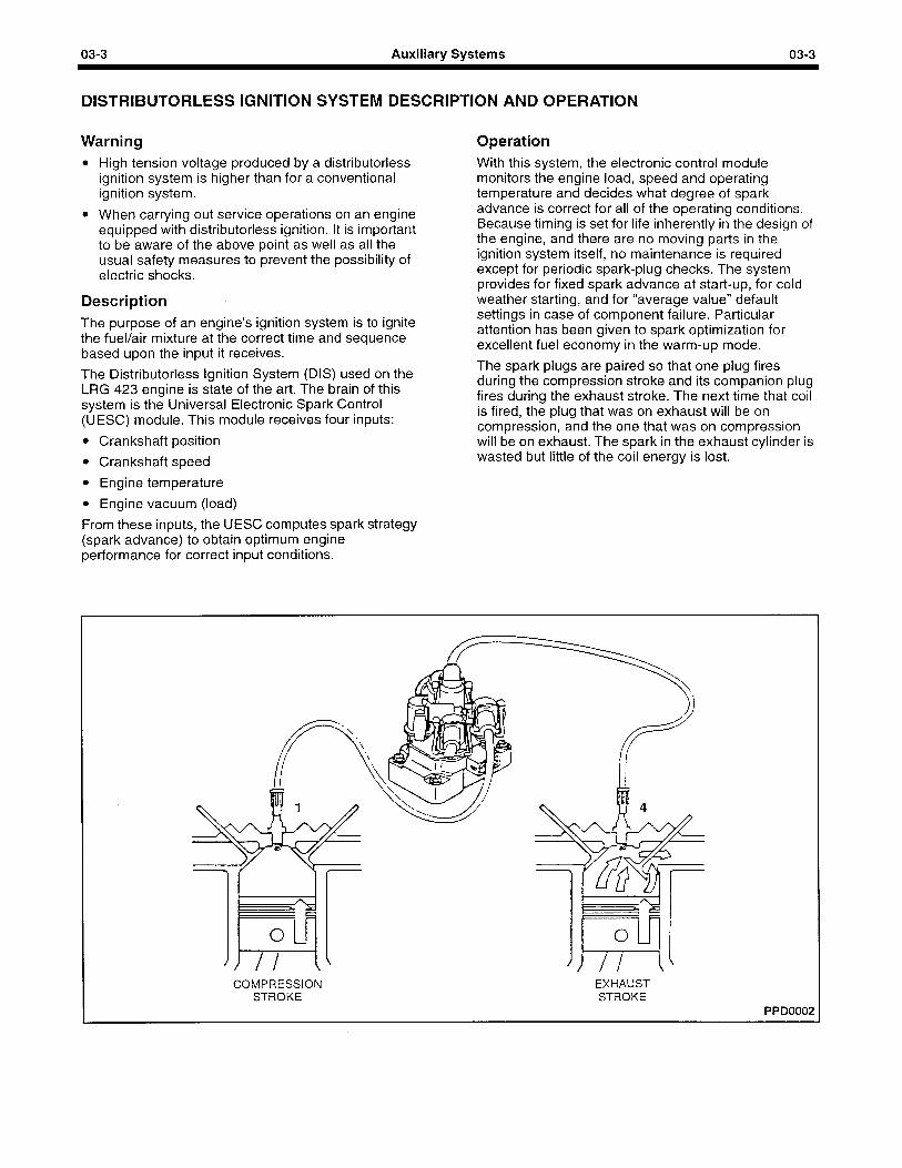
03-3 Auxiliary Systems 03-3
DISTRIBUTORLESS IGNITION SYSTEM DESCRIPTION AND OPERATION
Warning l High tension voltage produced by a distributorless
ignition system is higher than for a conventional ignition system.
l When carrying out service operations on an engine equipped with distributorless ignition. It is important to be aware of the above point as well as all the usual safety measures to prevent the possibility of electric shocks.
Description The purpose of an engine’s ignition system is to ignite the fuel/air mixture at the correct time and sequence based upon the input it receives.
The Distributorless Ignition System (DIS) used on the LRG 423 engine is state of the art. The brain of this system is the Universal Electronic Spark Control (UESC) module. This module receives four inputs:
l Crankshaft position
l Crankshaft speed
l Engine temperature
l Engine vacuum (load)
From these inputs, the UESC computes spark strategy (spark advance) to obtain optimum engine performance for correct input conditions.
Operation With this system, the electronic control module monitors the engine load, speed and operating temperature and decides what degree of spark advance is correct for all of the operating conditions. Because timing is set for life inherently in the design of the engine, and there are no moving parts in the ignition system itself, no maintenance is required except for periodic spark-plug checks. The system provides for fixed spark advance at start-up, for cold weather starting, and for “average value” default settings in case of component failure. Particular attention has been given to spark optimization for excellent fuel economy in the warm-up mode.
The spark plugs are paired so that one plug fires during the compression stroke and its companion plug fires during the exhaust stroke. The next time that coil is fired, the plug that was on exhaust will be on compression, and the one that was on compression will be on exhaust. The spark in the exhaust cylinder is wasted but little of the coil energy is lost.
COMPRESSION STROKE
EXHAUST STROKE
PPD0002
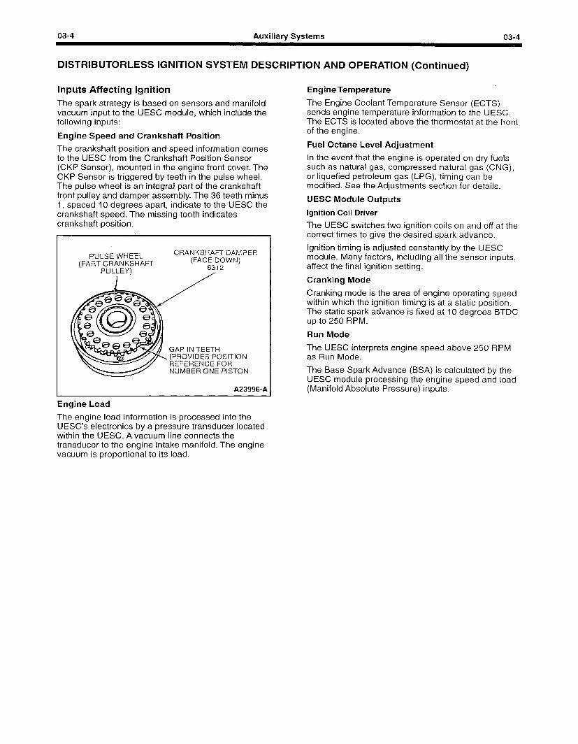
03-4 Auxiliary Systems 03-4
DISTRIBUTORLESS IGNITION SYSTEM DESCRIPTION AND OPERATION (Continued)
Inputs Affecting Ignition The spark strategy is based on sensors and manifold vacuum input to the UESC module, which include the following inputs:
Engine Speed and Crankshaft Position
The crankshaft position and speed information comes to the UESC from the Crankshaft Position Sensor (CKP Sensor), mounted in the engine front cover. The CKP Sensor is triggered by teeth in the pulse wheel. The pulse wheel is an integral part of the crankshaft front pulley and damper assembly. The 36 teeth minus 1, spaced IO degrees apart, indicate to the UESC the crankshaft speed. The missing tooth indicates crankshaft position.
PULSE WHEEL (PART CRANKSHAFT
PULLEY)
CRANKSHAFT DAMPER (FACE DOWN)
6312 /
GAP IN TEETH (PROVIDES POSITION REFERENCE FOR NUMBER ONE PISTON
A239960A
Engine Load
The engine load information is processed into the UESC’s electronics by a pressure transducer located within the UESC. A vacuum line connects the transducer to the engine intake manifold. The engine vacuum is proportional to its load.
Engine Temperature
The Engine Coolant Temperature Sensor (ECTS) sends engine temperature information to the UESC. The ECTS is located above the thermostat at the front of the engine.
Fuel Octane Level Adjustment
In the event that the engine is operated on dry fuels such as natural gas, compressed natural gas (CNG), or liquefied petroleum gas (LPG), timing can be modified. See the Adjustments section for details.
UESC Module Outputs
Ignition Coil Driver
The UESC switches two ignition coils on and off at the correct times to give the desired spark advance.
Ignition timing is adjusted constantly by the UESC module. Many factors, including all the sensor inputs, affect the final ignition setting.
Cranking Mode
Cranking mode is the area of engine operating speed within which the ignition timing is at a static position. The static spark advance is fixed at IO degrees BTDC up to 250 RPM.
Run Mode
The UESC interprets engine speed above 250 RPM as Run Mode.
The Base Spark Advance (BSA) is calculated by the UESC module processing the engine speed and load (Manifold Absolute Pressure) inputs.
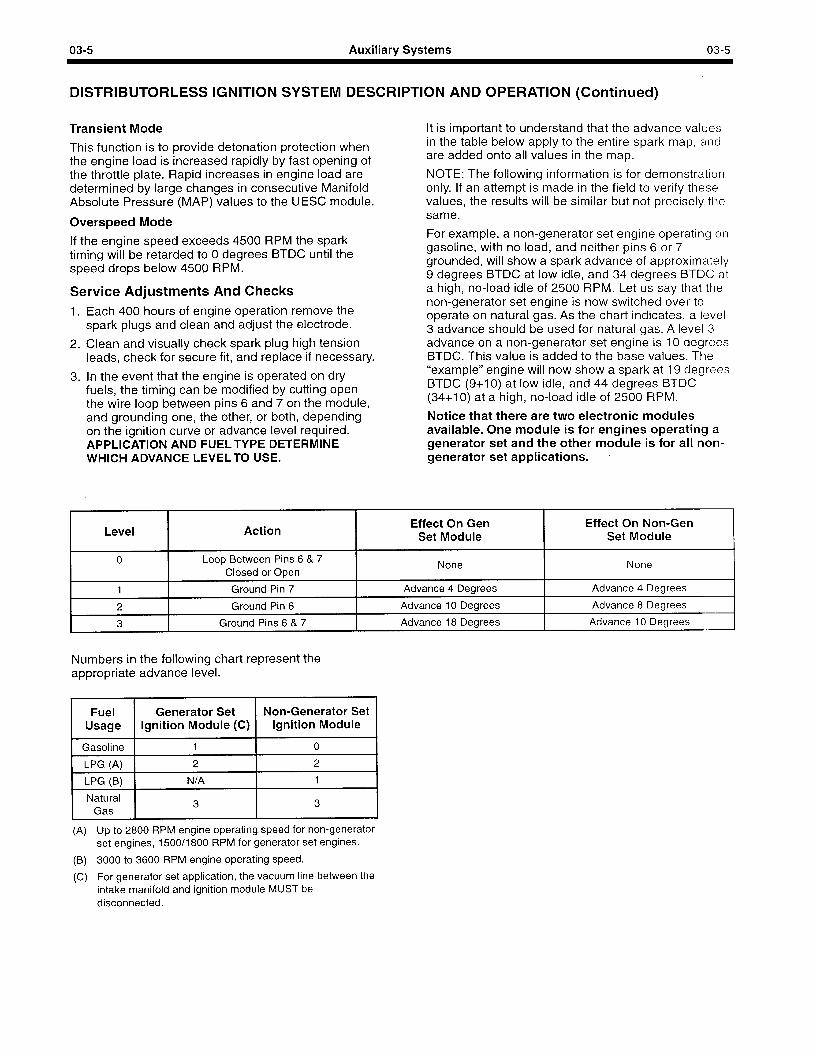
03-5 Auxiliary Systems 03-5
DISTRIBUTORLESS IGNITION SYSTEM DESCRIPTION AND OPERATION (Continued)
Transient Mode
This function is to provide detonation protection when the engine load is increased rapidly by fast opening of the throttle plate. Rapid increases in engine load are determined by large changes in consecutive Manifold Absolute Pressure (MAP) values to the UESC module.
Overspeed Mode
If the engine speed exceeds 4500 RPM the spark timing will be retarded to 0 degrees BTDC until the speed drops below 4500 RPM.
Service Adiustments And Checks Each 400 hours of engine operation remove the spark plugs and clean and adjust the electrode.
Clean and visually check spark plug high tension leads, check for secure fit, and replace if necessary.
In the event that the engine is operated on dry fuels, the timing can be modified by cutting open the wire loop between pins 6 and 7 on the module, and grounding one, the other, or both, depending on the ignition curve or advance level required. APPLICATION AND FUELTYPE DETERMINE WHICH ADVANCE LEVELTO USE.
It is important to understand that the advance values in the table below apply to the entire spark map, and are added onto all values in the map.
NOTE: The following information is for demonstration only. If an attempt is made in the field to verify these values, the results will be similar but not precisely the same.
For example, a non-generator set engine operating on gasoline, with no load, and neither pins 6 or 7 grounded, will show a spark advance of approximately 9 degrees BTDC at low idle, and 34 degrees BTDC at a high, no-load idle of 2500 RPM. Let us say that the non-generator set engine is now switched over to operate on natural gas. As the chart indicates, a level 3 advance should be used for natural gas. A level 3 advance on a non-generator set engine is 10 degrees BTDC. This value is added to the base values. The “example” engine will now show a spark at 19 degrees BTDC (9+10) at low idle, and 44 degrees BTDC (34+10) at a high, no-load idle of 2500 RPM.
Notice that there are two electronic modules available. One module is for engines operating a generator set and the other module is for all non- generator set applications.
Level
0
Action
Loop Between Pins 6 & 7 Closed or Open
Effect On Gen Set Module
None
Effect On Non-Gen Set Module
None
1 Ground Pin 7 Advance 4 Degrees Advance 4 Degrees
2 Ground Pin 6 Advance 10 Degrees Advance 8 Degrees
3 Ground Pins 6 & 7 Advance 18 Degrees Advance 10 Degrees
Numbers in the following chart represent the appropriate advance level.
Generator Set Non-Generator Set Ignition Module (C) Ignition Module
1 Gasoline 1 1 I 0 I
LPG (A)
LPG (B)
2 2
N/A 1
I Natural Gas I
3 I
3 I
(A) Up to 2800 RPM engine operating speed for non-generator set engines, 1500/1800 RPM for generator set engines.
(B) 3000 to 3600 RPM engine operating speed.
(C) For generator set application, the vacuum line between the intake manifold and ignition module MUST be disconnected.
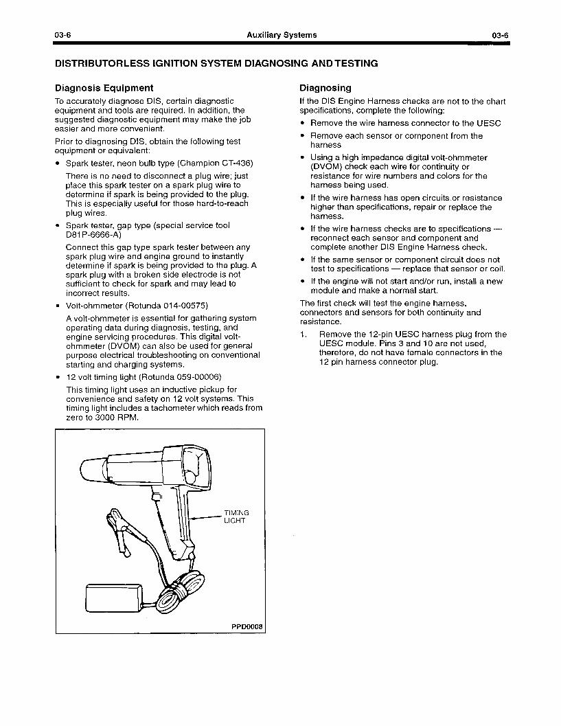
03-6 Auxiliary Systems 03-6
DISTRIBUTORLESS IGNITION SYSTEM DIAGNOSING AND TESTING
Diagnosis Equipment To accurately diagnose DIS, certain diagnostic equipment and tools are required. In addition, the suggested diagnostic equipment may make the job easier and more convenient.
Prior to diagnosing DIS, obtain the following test equipment or equivalent:
l Spark tester, neon bulb type (Champion CT-436)
There is no need to disconnect a plug wire; just place this spark tester on a spark plug wire to determine if spark is being provided to the plug. This is especially useful for those hard-to-reach plug wires.
l Spark tester, gap type (special service tool 081 P-6666-A)
Connect this gap type spark tester between any spark plug wire and engine ground to instantly determine if spark is being provided to the plug. A spark plug with a broken side electrode is not sufficient to check for spark and may lead to incorrect results.
l Volt-ohmmeter (Rotunda 014-00575)
A volt-ohmmeter is essential for gathering system operating data during diagnosis, testing, and engine servicing procedures. This digital volt- ohmmeter (DVOM) can also be used for general purpose electrical troubleshooting on conventional starting and charging systems.
l 12 volt timing light (Rotunda 059-00006)
This timing light uses an inductive pickup for convenience and safety on 12 volt systems. This timing light includes a tachometer which reads from zero to 3000 RPM.
Diagnosing If the DIS Engine Harness checks are not to the chart specifications, complete the following:
l Remove the wire harness connector to the UESC
l Remove each sensor or component from the harness
l Using a high impedance digital volt-ohmmeter (DVOM) check each wire for continuity or resistance for wire numbers and colors for the harness being used.
l If the wire harness has open circuitsor resistance higher than specifications, repair or replace the harness.
l If the wire harness checks are to specifications - reconnect each sensor and component and complete another DIS Engine Harness check.
l If the same sensor or component circuit does not test to specifications - replace that sensor or coil.
l If the engine will not start and/or run, install a new module and make a normal start.
The first check will test the engine harness, connectors and sensors for both continuity and resistance.
1. Remove the 12,pin UESC harness plug from the UESC module. Pins 3 and 10 are not used, therefore, do not have female connectors in the 12 pin harness connector plug.
TIMING LIGHT
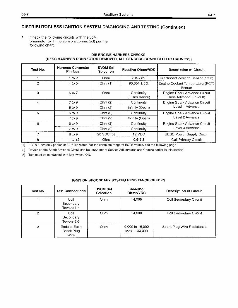
03-7 Auxiliary Systems 03-7
DISTRIBUTORLESS IGNITION SYSTEM DIAGNOSING ANDTESTING (Continued)
1. Check the following circuits with the volt- ohmmeter (with the sensors connected) per the following chart.
DIS ENGINE HARNESS CHECKS (UESC HARNESS CONNECTOR REMOVED, ALL SENSORS CONNECTED TO HARNESS)
Test No. Harness Connector
Pin Nos. DVOM Set Selection
Reading Ohms/VDC Description of Circuit /
1 1 to2 Ohm 315-385 I Crankshaft Position Sensor (CKP) 1
2 4 to 5 Ohm (1) 95,851 + 5% Engine Coolant Temperature (ECT) Sensor
3
4
6 to 7 Ohm Continuity Engine Spark Advance Circuit (0 Resistance) Base Advance (Level 0)
7 to 9 Ohm (2) Continuity Engine Spark Advance Circuit 6 to 9 Ohm (2) Infinity (Open) Level 1 Advance
5 6 to 9 Ohm (2) Continuity Engine Spark Advance Circuit 7 to 9 Ohm (2) Infinity (Open) Level 2 Advance
6 6 to 9 Ohm (2) Continuity Engine Spark Advance Circuit 7 to 9 Ohm (2) Continuity Level 3 Advance
7 8 to 9 20 VDC (3) 12 VDC UESC Power Supply Circuit
8 11 to 12 Ohm 0.5-I .3 Coil Primary Circuit
(1.) ECTS brass only portion in 32°F ice water. For the complete range of ECTS values, see the following page.
(2) Details on the Spark Advance Circuit can be found under Service Adjustments and Checks earlier in this section.
(3) Test must be conducted with key switch “ON.”
IGNITION SECONDARY SYSTEM RESISTANCE CHECKS
Test No. Test Connections
1
2
3
DVOM Set Reading Selection Ohms/VDC
Description of Circuit
Coil Secondary Towers 1-4
Ohm 14,000 Coil Secondary Circuit
Coil Secondary Towers 2-3
Ohm 14,000 Coil Secondary Circuit
Ends of Each Spark Plug
Wire
Ohm 9,000 to 16,000 Spark Plug Wire Resistance Max. - 30,000
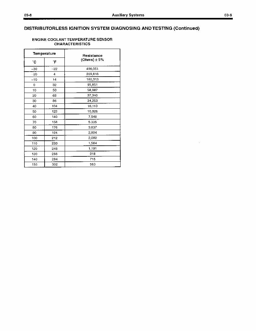
03-8 Auxiliary Systems 03-8
DISTRIBUTORLESS IGNITION SYSTEM DIAGNOSING ANDTESTING (Continued)
ENGINE COOLANTTEMPERATURE SENSOR CHARACTERISTICS
/ rmp;ratu: 1 Resistance
(Ohms) + 5%
-30 -22 496,051
-20 4 209,816
I -10 I 14 1 160,313 I
I 0 I 32 r- 95,851 I I 10 I 50 I 58,987 I I 20 1 68 1 37,340 I I 30 I 86 I 24,253 I I 40 I 104 I 16,113 I I 50 I 122 I 10,926 I I 60 1 140 I 7,548 I I 70 1 158 1 5,335 I I 80 1 176 1 3,837 I 11 194 I 2,804 I I 100 I 212 I 2,080 I
110 230 1,564
120 248 1,191
130 266 918
140 284 715
150 302 563
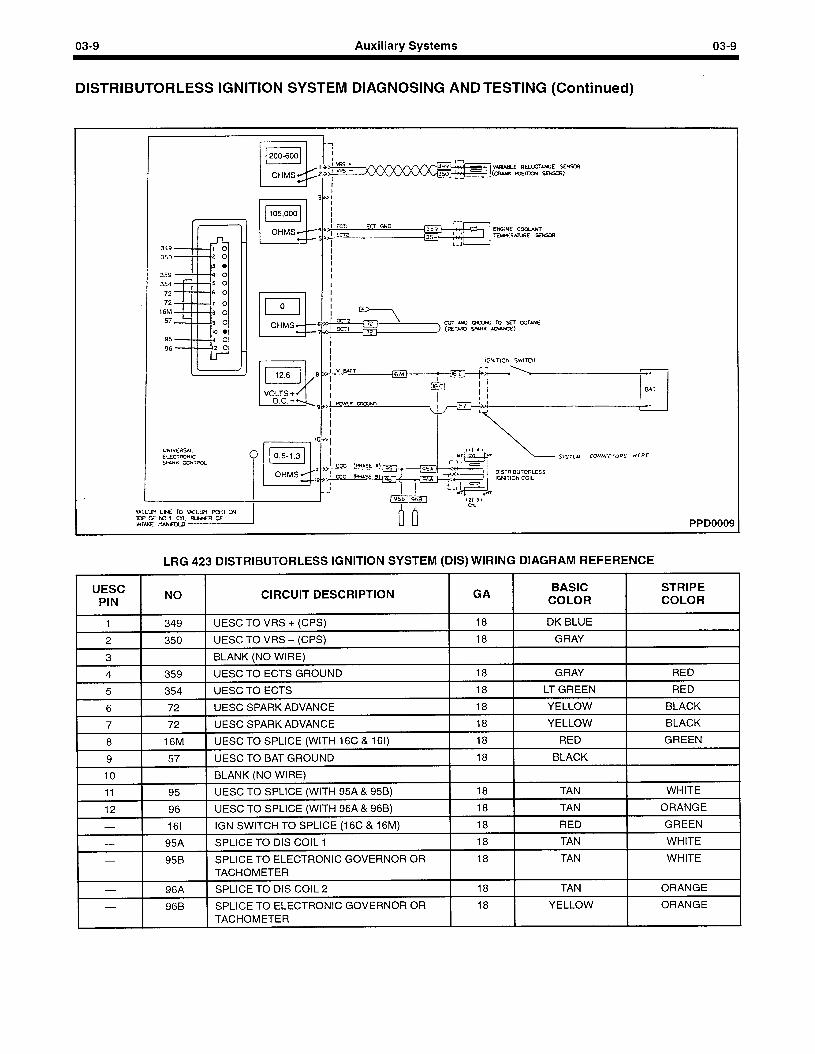
03-9 Auxiliary Systems 03-9
DISTRIBUTORLESS IGNITION SYSTEM DIAGNOSING AND TESTING (Continued)
PPD0009
LRG 423 DISTRIBUTORLESS IGNITION SYSTEM (DIS) WIRING DIAGRAM REFERENCE
UESC PIN
1
2
3
4
5
6
7
8
9
10
11
12
NO
349
350
359
354
72
72
16M
57
95
96
161
95A
95B
96A
96B
CIRCUIT DESCRIPTION
UESC TO VRS + (CPS)
UESC TO VRS - (CPS)
BLANK (NO WIRE)
UESC TO ECTS GROUND
UESC TO ECTS
UESC SPARK ADVANCE
UESC SPARK ADVANCE
UESC TO SPLICE (WITH 16C & 161)
UESC TO BAT GROUND
BLANK (NO WIRE)
UESC TO SPLICE (WITH 95A & 95B)
UESC TO SPLICE (WITH 96A & 96B)
IGN SWITCH TO SPLICE (16C & 16M)
SPLICE TO DIS COIL 1
SPLICE TO ELECTRONIC GOVERNOR OR TACHOMETER
SPLICE TO DIS COIL 2
SPLICE TO ELECTRONIC GOVERNOR OR TACHOMETER
GA
18
18
18
18
18
18
18
18
18
18
18
18
18
18
18
BASIC COLOR
DK BLUE
GRAY
GRAY
LT GREEN
YELLOW
YELLOW
RED
BLACK
TAN
TAN
RED
TAN
TAN
TAN
YELLOW
STRIPE COLOR
RED
RED
BLACK
BLACK
GREEN
WHITE
ORANGE
GREEN
WHITE
WHITE
ORANGE
ORANGE
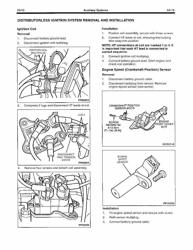
03-I 0 Auxiliary Systems 03-l 0
DISTRIBUTORLESS IGNITION SYSTEM REMOVAL AND INSTALLATION
Ignition Coil
Removal
1. Disconnect battery ground lead.
2. Disconnect ignition coil multiplug.
PPD0003
3. Compress 2 lugs and disconnect HT leads at coil.
PPD0004
Remove four screws and detach coil assembly.
PPD0005
Installation
1. Position coil assembly, secure with three screws.
2. Connect HT leads at coil, ensuring that locking tabs snap into position.
NOTE: HT connections at coil are marked 1 to 4. It is important that each HT lead is connected in correct sequence.
3. Connect ignition coil multiplug.
4. Connect battery ground lead. Start engine and check coil operation.
Engine Speed (Crankshaft Position) Sensor
Removal
1. Disconnect battery ground cable.
2. Disconnect multiplug from sensor. Remove engine speed sensor (one screw).
CRANKSHAFT- POSITION
N605892-S2 ER
(71-l 06 LB-IN)
A23933-A
ENGINE SPEED
SENSOR
Installation
1. Fit engine speed sensor and secure with screw.
2. Refit sensor multiplug.
3. Connect battery ground cable.
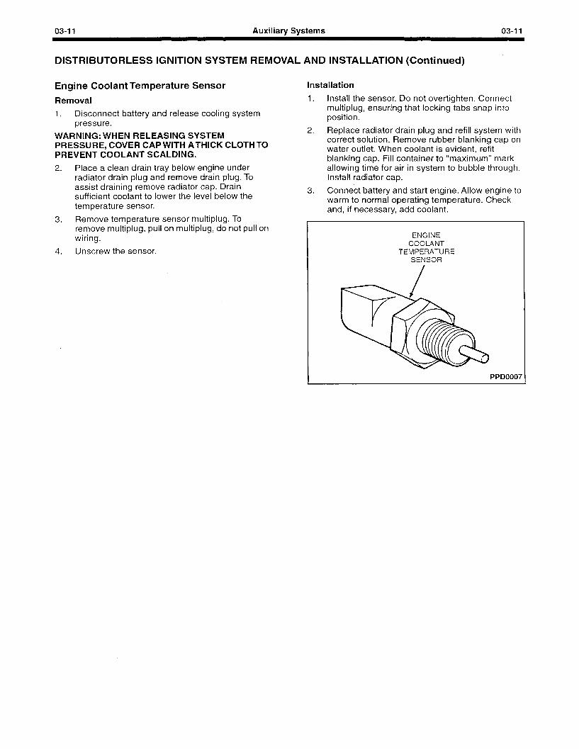
03-11 Auxiliary Systems 03-11
DISTRIBUTORLESS IGNITION SYSTEM REMOVAL AND INSTALLATION (Continued)
Engine Coolant Temperature Sensor
Removal
Installation
1. Install the sensor. Do not overtighten. Connect
1. Disconnect battery and release cooling system multiplug, ensuring that locking tabs snap into
bressure. position.
2. WAR’NING: WHEN RELEASING SYSTEM PRESSURE, COVER CAP WITH ATHICK CLOTHTO PREVENT COOLANT SCALDING.
Replace radiator drain plug and refill system with correct solution. Remove rubber blanking cap on water outlet. When coolant is evident, refit blanking cap. Fill container to “maximum” mark
2. Place a clean drain tray below engine under allowing time for air in system to bubble through. radiator drain plug and remove drain plug. To Install radiator cap. assist draining remove radiator cap. Drain sufficient coolant to lower the level below the temperature sensor.
3. Remove temperature sensor multiplug. To remove multiplug, pull on multiplug, do not pull on wiring.
4. Unscrew the sensor.
3. Connect battery and start engine. Allow engine to warm to normal operating temperature. Check and, if necessary, add coolant.
ENGINE COOLANT
TEMPERATURE SENSOR
PPD0007
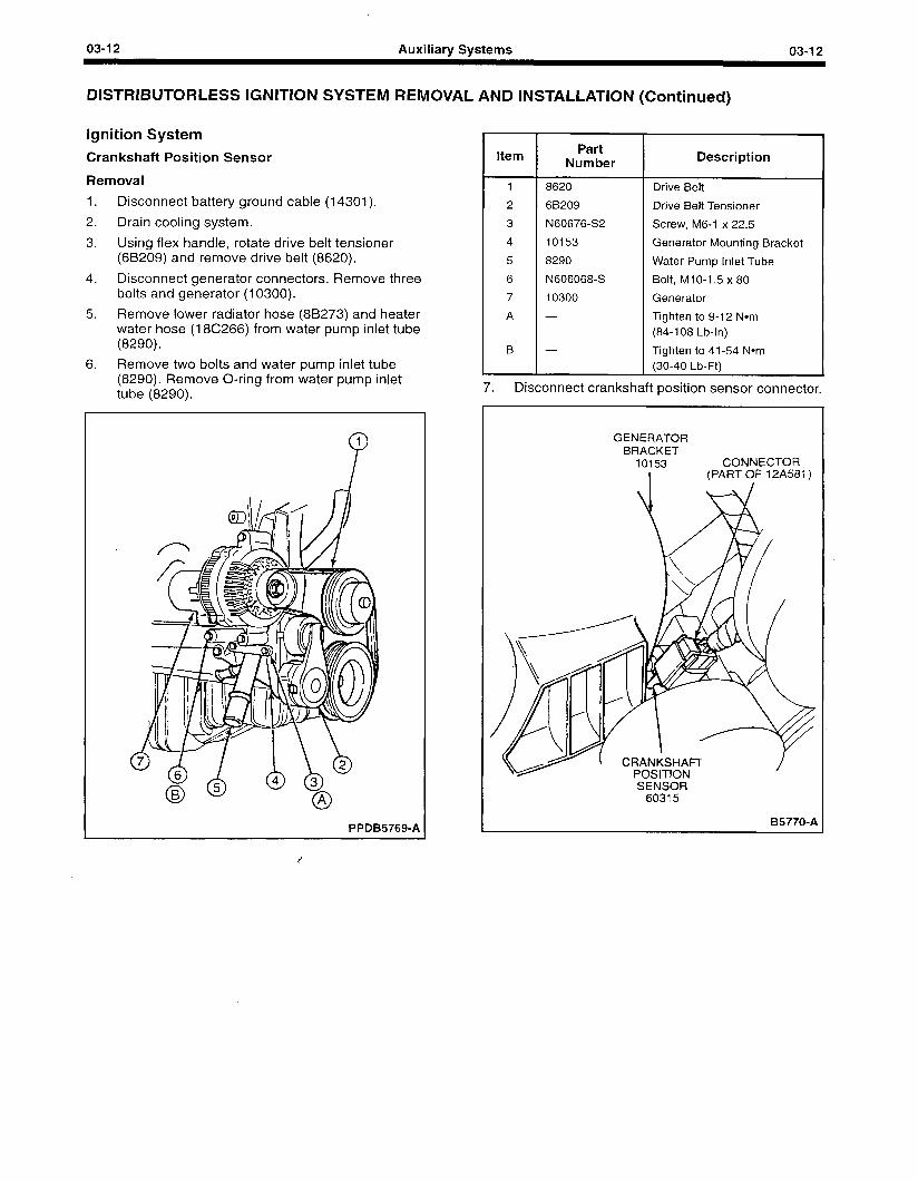
03-l 2 Auxiliary Systems 03-I 2
DISTRIBUTORLESS IGNITION SYSTEM REMOVAL AND INSTALLATION (Continued)
Ignition System
Crankshaft Position Sensor
Removal
1. Disconnect battery ground cable (14301).
2. Drain cooling system.
3. Using flex handle, rotate drive belt tensioner (6B209) and remove drive belt (8620).
4. Disconnect generator connectors. Remove three bolts and generator (10300).
5. Remove lower radiator hose (8B273) and heater water hose (18C266) from water pump inlet tube (8290).
6. Remove two bolts and water pump inlet tube (8290). Remove O-ring from water pump inlet tube (8290).
PPDB5769-A
Item
1
2
3
4
5
6
7
A
B
Part Number
8620
68209
N60676-S2
10153
8290
N606068-S
10300
-
-
Description
Drive Belt
Drive Belt Tensioner
Screw, M6-1 x 22.5
Generator Mounting Bracket
Water Pump Inlet Tube
Bolt, MIO-1.5 x 80
Generator
Tighten to 9-12 Nom (84-l 08 Lb-In)
Tighten to 41-54 Nom (30-40 Lb-Ft)
7. Disconnect crankshaft position sensor connector.
GENERATOR BRACKET
10153 CONNECTOR I (PART OF 12A581)
SENSOR 60315
B5770-A
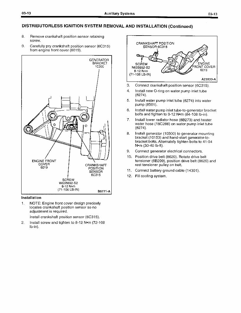
03-l 3 Auxiliary Systems 03-I 3
DISTRIBUTORLESS IGNITION SYSTEM REMOVAL AND INSTALLATION (Continued)
8. Remove crankshaft position sensor retaining screw.
9. Carefully pry crankshaft position sensor (6C315) from engine front cover (6019).
GENERATOR BRACKET
10300
ENGINE FRONT COVER
6019 CRANKSHAFI-
POSITION SENSOR
6C315
SCREW W605892-S2
8-12 Nom (71-l 06 LB-IN) 95771 -A
Installation
1. NOTE: Engine front cover design precisely locates crankshaft position sensor so no adjustment is required.
Install crankshaft position sensor (6C315).
2. Install screw and tighten to 8-12 Nom (72-l 08 lb-in).
N
(71
CRANKSHAFl- POSITION -
t SCREW
SENSOR-6C315
605892-S2 8-12 Narn -106 LB-IN)
6019 ‘ER
A23933-A
3. Connect crankshaft position sensor (6C315).
4. Install new O-ring on water pump inlet tube (8274).
5. Install water pump inlet tube (8274) into water pump (8501).
6. Install water pump inlet tube-to-generator bracket bolts and tighten to 9-12 Nom (84-l 08 lb-in).
7. Install lower radiator hose (88273) and heater water hose (18C266) on water pump inlet tube (8274).
8. Install generator (10300) to generator mounting bracket (10153) and hand-start generator-to- bracket bolts. Alternately tighten bolts to 41-54 Nom (30-40 lb-ft).
9. Connect generator electrical connectors.
10. Position drive belt (8620). Rotate drive belt tensioner (68209), position drive belt (8620) and rest tensioner pulley on belt.
11. Connect battery ground cable (14301).
12. Fill cooling system.
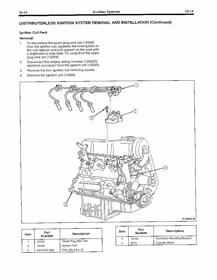
03-l 4 Auxiliary Systems 03-I 4
DISTRIBUTORLESS IGNITION SYSTEM REMOVAL AND INSTALLATION (Continued)
Ignition Coil Pack
Removal
1. To disconnect the spark plug wire set (12259) from the ignition coil, squeeze the locking tabs on the coil retainer and pull upward on the boot with a slight side-to-side twist. Do not pull on the spark plug wire set (12259).
2. Disconnect the engine wiring harness (12A200) electrical connector from the ignition coil (12029).
3. Remove the four ignition coil retaining screws.
4. Remove the ignition coil (12029).
0 4
v10045-P
Item
1
2
3
Part Number
12259
12029
N606502-S36
Description
Spark Plug Wire Set
Ignition Coil
Bolt, M5-0.8 x 37
I I Item Part
Number Description
4 10153 Generator Mounting Bracket
5 6010 Cylinder Block
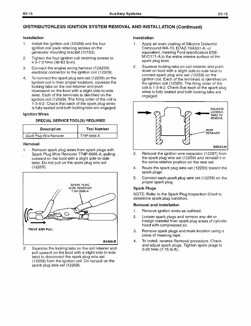
03-15 Auxiliary Systems 03-l 5
DISTRIBUTORLESS IGNITION SYSTEM REMOVAL AND INSTALLATION (Continued)
Installation
1. Install the ignition coil (12029) and the four ignition coil pack retaining screws on the generator mounting bracket (10153).
2. Tighten the four ignition coil retaining screws to 4.5-7.0 Nom (36-63 lb-in).
3. Connect the engine wiring harness (12A200) electrical connector to the ignition coil (12029).
4. To connect the spark plug wire set (12259) on the ignition coil in their proper locations, squeeze the locking tabs on the coil retainer and push downward on the boot with a slight side-to-side twist. Each of the terminals is identified on the ignition coil (12029). The firing order of the coil is 1-3-4-2. Check that each of the spark plug wires is fully seated and both locking tabs are engaged.
Ignition Wires
SPECIAL SERVICE TOOL(S) REQUIRED
Description Tool Number
Spark Plug Wire Remover T74P-6666-A
Removal
1. Remove spark plug wires from spark plugs with
\ Spark Plug Wire Remover T74P-6666-A, pulling outward on the boot with a slight side-to-side twist. Do not pull on the spark plug wire set (12259).
SPARK PLUG WIRE REMOVER
T74P-6666-A
TWIST AND PULL
B3496-E
2. Squeeze the locking tabs on the coil retainer and pull upward on the boot with a slight side-to-side twist to disconnect the spark plug wire set (12259) from the ignition coil. Do not pull on the spark plug wire set (12259).
Installation
1. Apply an even coating of Silicone Dielectric Compound WA-1 0, D7AZ-19A331 -A, or equivalent, meeting Ford specification ESE- Ml Cl 71 -A to the entire interior surface of the spark plug boot.
2. Squeeze locking tabs on coil retainer and push down on boot with a slight side-to-side twist to connect spark plug wire set (12259) on the ignition coil. Each of the terminals is identified on the ignition coil (12029). The firing order of the coil is 1-3-4-2. Check that each of the spark plug wires is fully seated and both locking tabs are engaged.
SQUEEZE
- gs”‘T”oG
-
REMOVE
WIRE RETAINER
B4253-B
3. Remove the ignition wire separator (12297) from the spark plug wire set (12259) and reinstall it in the same relative position on the new set.
4. Route the spark plug wire set (12259) toward the spark plugs.
5. Connect each spark plug wire set (12259) on the proper spark plug.
Spark Plugs
NOTE: Refer to the Spark Plug Inspection Chart to determine spark plug condition.
Removal and Installation
1. Remove ignition wires as outlined.
2. Loosen spark plugs and remove any dirt or foreign material from spark plug areas of cylinder head with compressed air.
3. Remove spark plugs and mark location using a piece of masking tape.
4. To install, reverse Removal procedure. Check and adjust spark plugs. Tighten spark plugs to 9-20 Nom (7-15 lb-ft).
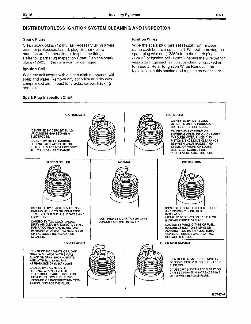
03-l 6 Auxiliary Systems 03-I 6
DISTRIBUTORLESS IGNITION SYSTEM CLEANING AND INSPECTION
Spark Plugs
Clean spark plugs (12405) as necessary using a wire brush or professional spark plug cleaner (follow manufacturer’s instructions). Inspect the firing tip. Refer to Spark Plug Inspection Chart. Replace spark plugs (12405) if they are worn or damaged.
Ignition Coil
Ignition Wires
Wipe the spark plug wire set (12259) with a clean, damp cloth before inspecting it. Without removing the spark plug wire set (12259) from the spark plugs (12405) or ignition coil (12029) inspect the wire set for visible damage such as cuts, pinches, or cracked or torn boots. Refer to Ignition Wires Removal and Installation in this section and replace as necessary.
Wipe the coil towers with a clean cloth dampened with soap and water. Remove any soap film and dry with compressed air. Inspect for cracks, carbon tracking and dirt.
Spark Plug Inspection Chart
GAP BRIDGED
IDENTIFIED BY DEPOSIT BUILD- UP CLOSING GAP BETWEEN ELECTRODES.
CAUSED BY OIL OR CARBON FOULING, REPLACE PLUG, OR IF DEPOSITS ARE NOT EXCESSIVE THE PLUG CAN BE CLEANED.
OIL FOULED
IDENTIFIED BY WET BLACK DEPOSITS ON THE INSULATOR SHELL BORE ELECTRODES.
CAUSED BY EXCESSIVE OIL ENTERING COMBUSTION CHAMBER THROUGH WORN RINGS AND PISTONS, EXCESSIVE CLEARANCE BETWEEN VALVE GUIDES AND STEMS, OR WORN OR LOOSE BEARINGS. CORRECT OIL PROBLEM. REPLACE THE PLUG.
ELECTRODES.
CAUSED BY TOO COLD A PLUG, NER, DEFECTIVE FUEL
H A FUEL MIXTURE, PERATING HEAT RISER IDLING. CAN BE
IDENTIFIED BY LIGHT TAN OR GRAY METALLIC DEPOSiTS ON INSULATOR
DEPOSITS ON THE FIRING TIP. INDICATE ENGINE DAMAGE.
CAUSED BY WRONG
IDENTIFIED BY A WHITE OR LIGHT GRAY tNSULATOR WITH SMALL BLACK OR GRAY BROWN SPOTS AND WITH BLUISH-BURNT APPEARANCE OF ELECTRODES.
IDENTIFIED BY MELTED OR SPOrrY DEPOSITS RESEMBLING BUBBLES OR BLISTERS.
CAUSED BY ENGINE OVER- HEATING, WRONG IYPE OF FUEL, LOOSE SPARK PLUGS. TOO HOT A PLUG, LOW FUEL PUMP PRESSURE OR INCORRECT IGNITION TIMING. REPLACE THE PLUG.
CAUSED BY SUDDEN ACCELERATION. CAN BE CLEANED IF NOT EXCESSIVE, OTHERWISE REPLACE PLUG.
B5747-1
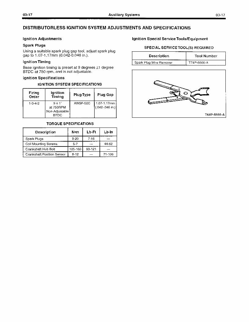
03-I 7 Auxiliary Systems 03-I 7
DISTRIBUTORLESS IGNITION SYSTEM ADJUSTMENTS AND SPECIFICATIONS
Ignition Adjustments Ignition Special Service Tools/Equipment
Spark Plugs
Using a suitable spark plug gap tool, adjust spark plug gap to 1.07-I .I 7mm (0.042-0.046 in.).
Ignition Timing
SPECIAL SERVICE TOOL(S) REQUIRED
Description Tool Number
Spark Plug Wire Remover T74P-6666-A
Base ignition timing is preset at 9 degrees *I degree BTDC at 750 rpm, and is not adjustable.
Ignition Specifications
IGNITION SYSTEM SPECIFICATIONS
1 ~~~~ / l+$ii’$’ 1 Plug Type 1 Plug Gap /
AWSF52C 1.07-I .17mm (.042-.046 in.)
TORQUE SPECIFICATIONS
Description 1 Nom 1 Lb-Ft 1 Lb-In 1
Spark Plugs
Coil Mounting Screws
9-20 7-15 -
5-7 - 44-62
1 Crankshaft Hub Bolt 1125-165 1 93-121 1 - 1
T64P-6666-A
1 Crankshaft Position Sensor 1 8-12 1 - 1 71-106 1
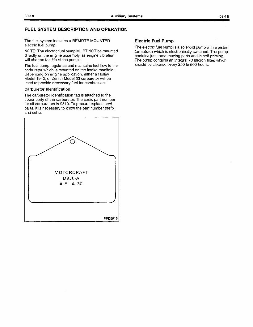
03-l 8 Auxiliary Systems 03-I 8
FUEL SYSTEM DESCRIPTION AND OPERATION
The fuel system includes a REMOTE-MOUNTED electric fuel pump.
NOTE: The electric fuel pump MUST NOT be mounted directly on the engine assembly, as engine vibration will shorten the life of the pump.
The fuel pump regulates and maintains fuel flow to the carburetor which is mounted on the intake manifold. Depending on engine application, either a Holley Model 1940, or Zenith Model 33 carburetor will be used to provide necessary fuel for combustion.
Carburetor Identification
The carburetor identification tag is attached to the upper body of the carburetor. The basic part number for all carburetors is 9510. To procure replacement parts, it is necessary to know the part number prefix and suffix.
MOTORCRAFT D9JL-A
A5 A30
PPDOOIO
Electric Fuel Pump The electric fuel pump is a solenoid pump with a piston (armature) which is electronically switched. The pump contains just three moving parts and is self-priming. The pump contains an integral 70 micron filter, which should be cleaned every 250 to 500 hours.
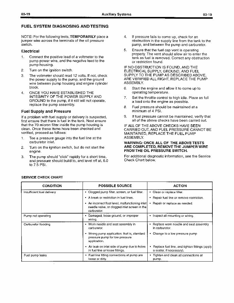
03-I 9 Auxiliary Systems 03-l 9
FUEL SYSTEM DIAGNOSING AND TESTING
NOTE: For the following tests,TEMPORARILY place a jumper wire across the terminals of the oil pressure switch.
Electrical 1. Connect the positive lead of a voltmeter to the
pump power wire, and the negative lead to the pump housing.
2. Turn on the ignition switch.
3. The voltmeter should read 12 volts. If not, check the power supply to the pump, and the ground wire between pump housing and engine cylinder block.
4. ONCE YOU HAVE ESTABLISHED THE INTEGRITY OF THE POWER SUPPLY AND GROUND to the pump, if it still will not operate, replace the pump assembly.
Fuel Supply and Pressure If a problem with fuel supply or delivery is suspected, first ensure that there is fuel in the tank. Next ensure that the 70 micron filter inside the pump housing is clean. Once these items have been checked and verified, proceed as follows:
1. Tee a pressure gauge into the fuel line at the carburetor inlet.
2. Turn on the ignition switch, but do not start the engine.
3. The pump should “click” rapidly for a short time, and pressure should build to, and level off at, 6.0 to 7.5 PSI.
SERVICE CHECK CHART
4. If pressure fails to come up, check for an obstruction in the supply line from the tank to the pump, and between the pump and carburetor.
5. Ensure that the fuel cap vent is operating properly. The vent should allow air to enter the tank as fuel is removed. Correct any obstruction or restriction found.
IF NO OBSTRUCTION IS FOUND, AND THE ELECTRICAL SUPPLY, GROUND, AND FUEL SUPPLY TO THE PUMP AS DESCRIBED ABOVE, ARE VERIFIED ALL RIGHT, REPLACE THE PUMP ASSEMBLY.
6. Start the engine and allow it to come up to operating temperature.
7. Set the throttle control to high idle. Place as full a load onto the engine as possible.
8. Fuel pressure should be maintained at a minimum of 4 PSI.
9. If fuel pressure cannot be maintained, verify that all of the above checks have been carried out.
IF ALL OF THE ABOVE CHECKS HAVE BEEN CARRIED OUT, AND FUEL PRESSURE CANNOT BE MAINTAINED, REPLACE THE FUEL PUMP ASSEMBLY.
WARNING: ONCE ALL OF THE ABOVETESTS ARE COMPLETED, REMOVE THE JUMPER WIRE FROM THE OIL PRESSURE SWITCH.
For additional diagnostic information, see the Service Check Chart below.
CONDITION
lnsuff icient fuel delivery
Pump not operating
Carburetor flooding
1 Fuel pump leaks
POSSIBLE SOURCE
l Clogged pump filter, screen, or fuel filter.
l A break or restriction in fuel lines.
l An incorrect float level, malfunctioning inlet needle valve, or clogged inlet screen in the carburetor.
l Damaged, loose ground, or improper wiring.
l Worn needle and seat assembly in l Replace worn needle and seat assembly carburetor. in carburetor.
l Wrong pump application: that is, standard pressure pump for low pressure application.
l Air leak on inlet side of pump due to holes in fuel line or loose fittings.
l Fuel line fitting connections at pump are loose or dirty.
ACTION I l Clean or replace filter.
l Repair fuel line or remove restriction.
l Repair or replace as needed.
l Inspect all mounting or wiring.
l Change to a low pressure pump
l Replace fuel line, and tighten fittings (apply a sealer, if necessary).
pump-
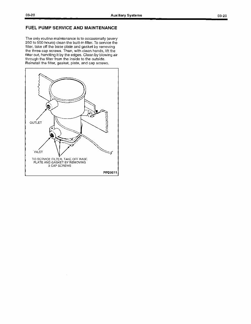
03-20 Auxiliary Systems 03-20
FUEL PUMP SERVICE AND MAINTENANCE
The only routine maintenance is to occasionally (every 250 to 500 hours) clean the built-in filter. To service the filter, take off the base plate and gasket by removing the three cap screws. Then, with clean hands, lift the filter out, handling it by the edges. Clean by blowing air through the filter from the inside to the outside. Reinstall the filter, gasket, plate, and cap screws.
0
TO SERVICE FILTER, TAKE OFF BASE PLATE AND GASKET BY REMOVING
3 CAP SCREWS
PPDOOI 1
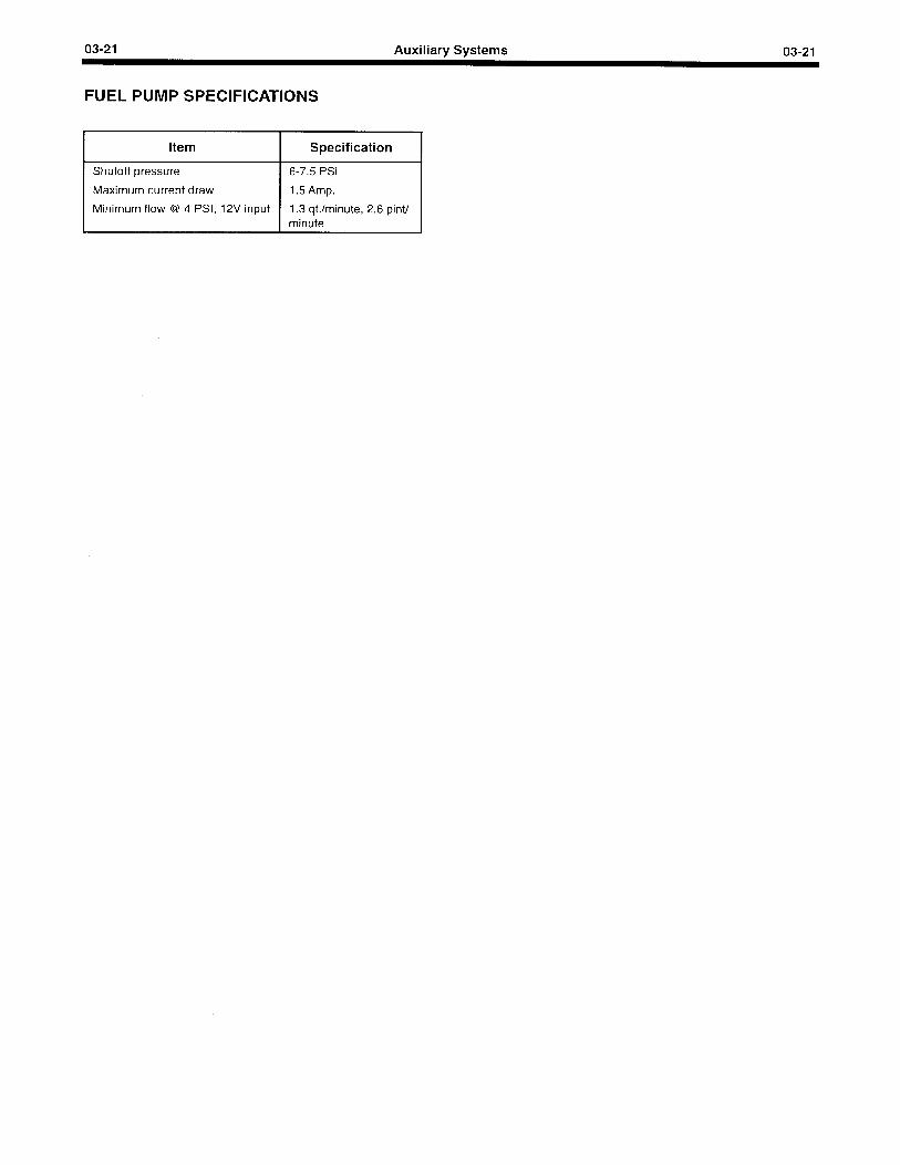
03-21 Auxiliary Systems 03-21
FUEL PUMP SPECIFICATIONS
Item Specification
Shutoff pressure 6-7.5 PSI
Maximum current draw 1.5 Amp.
Minimum flow @ 4 PSI, 12V input 1.3 qt./minute, 2.6 pint/ minute
03-22 Auxiliary Systems 03-22
CARBURETOR DIAGNOSIS
General Information Water and dirt that accumulate in the fuel tank can cause a restricted fuel line or filter and malfunction of the fuel pump or carburetor. Condensation, which is the greatest source of water entering the fuel tank, is formed by moisture in the air when it strikes the cold interior walls of the fuel tank.
If the accumulation of dirt and water in the filter is excessive, the fuel tank should be removed and flushed, and the line from the fuel pump to the tank should be blown out. Air leakage in the fuel inlet line can cause low fuel pump pressure and volume.
A restricted fuel tank vent can cause low fuel pump pressure and volume and can result in collapsed inlet hoses or a collapsed fuel tank. High or low pressure are the two most likely fuel pump troubles that will affect engine performance. Low pressure will cause a lean mixture and fuel starvation at high speeds, and excessive pressure will cause high fuel consumption and carburetor flooding.
Dirt accumulation in the fuel and air passages, improper idle adjustments, and improper fuel level are the major sources of carburetor troubles.
Many problems attributed to the carburetor are caused by other systems. Proper and careful diagnosis is a must.
If the problem seems to occur in one engine cylinder, the ignition system may be at fault. If the problem seems to occur in all engine cylinders, then the problem most likely is carburetion. When the carburetor is thought to be at fault, check the fuel system first. Dirt or water in the gas tank, leaks in the fuel lines, or a defective fuel pump often show the same symptoms as carburetion problems. Observation, pressure and volume tests on the fuel system show whether the fuel system is the cause of the problem.
When the carburetor is shown to be at fault, a simple cleaning may often solve the problem. Spraying a carburetor cleaning solvent into the carburetor’s air intake assembly with the engine running may solve the problem.
Percolation Percolation symptoms are a strong smell of fuel vapors and hard starting of a hot engine that has been sitting for 20 minutes. Fuel dripping from the end of the throttle shaft or from the main discharge nozzle causes a rich mixture in the air intake. Opening the choke completely and cranking the engine clears the vapors and eliminates percolation.
Flooding Flooding occurs from a float level set too high, a sticking choke plate, float, or float valve, or a fuel inlet needle held off its seat either by improper seating or dirt particles. A punctured or leaking float admitting fuel becomes gas-logged causing a heavy float, high fuel level and flooding.
If flooding does occur, disassemble the carburetor, observe the operation and condition of components, and repair or replace as necessary.
A ruptured accelerator pump diaphragm in th e Zen ith carburetor will cause a rich mixture condition simila r to flooding.
Hard Starting Hard starting when attributed to the carburetor is caused by a flooded engine due to improper starting procedures. An improper idle fuel mixture, sometimes due to improper fuel mixture, or idle fuel mixture adjusting needles not turned equally in relation to the other adjusting needle causes hard starting. A too-high or too-low float level due to misjudgments or wear, also cause hard starting. Repair, adjust or replace components as necessary.
Stalling Improper idle air/fuel mixture or an idle speed set too low causes an engine to stall. Adjust these systems as necessary. The stalling problem may be due to a loose throttle shaft in the bore of the throttle body. Repair as necessary. Clogged idle air bleeds, idle air passages, or an idle discharge port cause stalling. Cleaning eliminates this problem. Carburetor icing is also a cause of stalling.
Rough Idle An improper idle air/fuel mixture can cause rough idle. This may be due to improper adjustment or damaged, worn or grooved idle mixture adjusting screws. Rough idle is caused by too high or too low a fuel level due to floats misadjusted or damaged. A leak between the carburetor and intake manifold due to a carburetor not tightened down, a damaged gasket or a crack in either the carburetor or intake manifold, cause rough idle. Adjust, repair, or replace as necessary. Clogged idle air bleeds, restricted idle air passages or idle discharge ports also cause rough idle. Clean or repair as necessary.
Surging Above Idle Surging above idle is caused by a fuel level too low, due to an improperly adjusted float, clogged main jets, restricted main jet passages, or main jet having a size not suited for the application. Adjust, clean, or replace as necessary.
Poor Acceleration Poor acceleration is caused by a mixture being too rich or too lean. If a rich mixture is the cause of poor acceleration, the fault may be an improperly adjusted accelerator pump, a fuel level too high due to damaged or misadjusted floats, fuel inlet needle not seating due to damage or restriction, restricted air bleeds, or a worn or damaged main jet. Adjust, repair or replace as necessary.
03-23 Auxiliary Systems 03-23
CARBURETOR DIAGNOSIS (Continued)
If a lean mixture is the cause of poor acceleration, the fault may be an improperly adjusted accelerator pump, a damaged accelerator pump piston cap, an accelerating pump check valve that is missing, damaged, or not seating, a fuel float level set too low, a clogged main metering jet, or a restricted main fuel passage. Air leaks are also responsible for a lean mixture causing poor acceleration. Leaks may occur at the carburetor base to the intake manifold, or the intake manifold to the cylinder head. Cracks in the assemblies or worn gaskets cause these air leaks. Clean, adjust, repair or replace as necessary.
Inconsistent Idle Speed Inconsistent idle speed is mostly a throttle-related problem. An incorrect throttle linkage adjustment, a binding throttle linkage, a sticking throttle shaft, or a loose throttle shaft in the throttle body or bore can cause inconsistent idle speed. A sticking fuel inlet needle can also cause this problem. Repair, replace or adjust as necessary.
Reduced Power Output Reduced power output opened, an improperly
is caused by a adjusted throttl
throttle not opening fully, a main jet not suited for this application, or clogged main jets, main fuel passage, or air bleeds. Clean, adjust, repair, or replace as necessary.
choke not fully e linkage, a
Leaking Carburetor The causes of a carburetor leaking fuel are loose fuel connections or a cracked carburetor body. Repair or replace as needed.
03-24 Auxiliary Systems 03-24
ZENITH MODEL #33 CARBURETOR OPERATION AND SERVICE
The Zenith model #33 carburetor is a single downdraft unit of two-piece construction, consisting of a cast aluminum air intake and throttle body with a fuel bowl. The single venturi is removable for easy adaptability to meet different size engine requirements.
The mounting flange holes are elongated to allow it to fit either the SAE 1" or 1 l/4” flange. A vacuum- operated accelerator pump is used.
Fuel Supply System
The fuel supply system consists of the threaded fuel inlet connection and fuel valve seat, fuel valve, float and fuel chamber. The fuel supply line is connected to the threaded inlet. Gasoline passes through the connection, through the fuel valve seat and past the fuel valve and into the fuel chamber. The level of the fuel in the fuel chamber is regulated by the float through its control of the fuel valve. The fuel valve does not open and close alternately. It assumes a more or less fixed-opening position as regulated by the float, sufficient to maintain a proper level in the fuel chamber equal to the fuel demand of the engine according to its speed and load.
Idle System
The idle system supplies fuel to run the engine at curb idle and also slow speeds until sufficient velocity is built up in the main venturi to operate the main system.
This system consists of the idle discharge holes, the idle adjusting needle, the passage or channel between the idle jet and the discharge holes, the idle air bleed, and the idle jet and pickup tubes. At idling speeds, manifold vacuum is transmitted through the primary idle discharge hole to the idle jet through a passage running through the throttle and air intake bodies. Fuel from the fuel bowl flows through the main jet into the fuel well where it is picked up by the pickup tube to be metered by the idle jet. As the fuel leaves the idle jet it is mixed with air from the idle air bleed, which is located just above the jet in the air intake, therefore a fuel and air mixture is provided just before the passage to the idle discharge holes. This air bleed calibration is to provide better control of the fuel delivery and to prevent the fuel in the bowl from being siphoned into the intake manifold through the idle system when the engine is shut off.
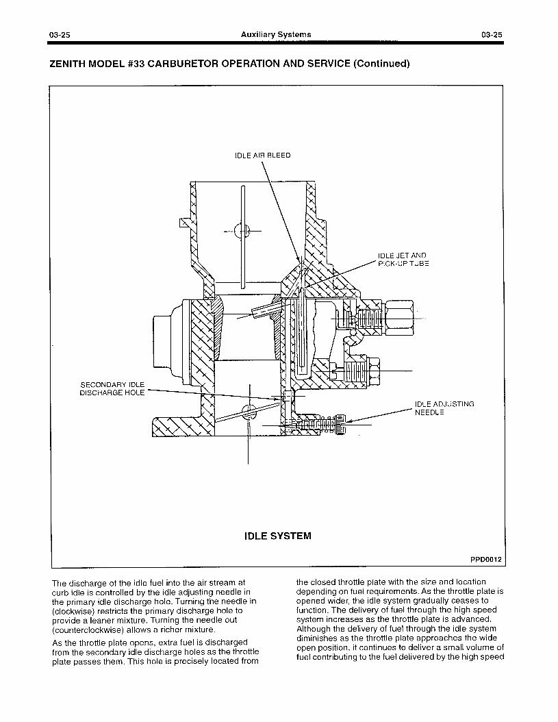
03-25 Auxiliary Systems 03-25
ZENITH MODEL #33 CARBURETOR OPERATION AND SERVICE (Continued)
SECONDARY IDLE DISCHARGE HOLE
IDLE AIR BLEED
IDLE JET AND PICK-UP TUBE
IDLE ADJUSTING
IDLE SYSTEM
PPD0012
The discharge of the idle fuel into the air stream at curb idle is controlled by the idle adjusting needle in the primary idle discharge hole. Turning the needle in (clockwise) restricts the primary discharge hole to provide a leaner mixture. Turning the needle out (counterclockwise) allows a richer mixture.
As the throttle plate opens, extra fuel is discharged from the secondary idle discharge holes as the throttle plate passes them. This hole is precisely located from
the closed throttle plate with the size and location depending on fuel requirements. As the throttle plate is opened wider, the idle system gradually ceases to function. The delivery of fuel through the high speed system increases as the throttle plate is advanced. Although the delivery of fuel through the idle system diminishes as the throttle plate approaches the wide open position, it continues to deliver a small volume of fuel contributing to the fuel delivered by the high speed
03-26 Auxiliary Systems 03-26
ZENITH MODEL #33 CARBURETOR OPERATION AND SERVICE (Continued)
system. It cannot be said that the idle system ceases to deliver fuel entirely at wide open throttle, but it must be made clear that the amount of fuel delivered from the idle system at wide open throttle is minute and relatively unimportant.
High Speed System
The high speed system consists of a venturi, a main jet, a well vent, and a well tube. This system also controls the mixture at part throttle speed.
The main jet controls fuel delivery from about one- quarter to three-quarters throttle opening. To maintain a proper mixture ratio, a small amount of air is admitted through the well vent. There are also air bleed holes located in the well tube at a point below the level of fuel in the well. Introducing air into the well tube below the level of fuel, reduces the surface tension of the fuel and helps fuel flow at low suction. This bleed also restricts fuel flow through the main jet under high suctions.
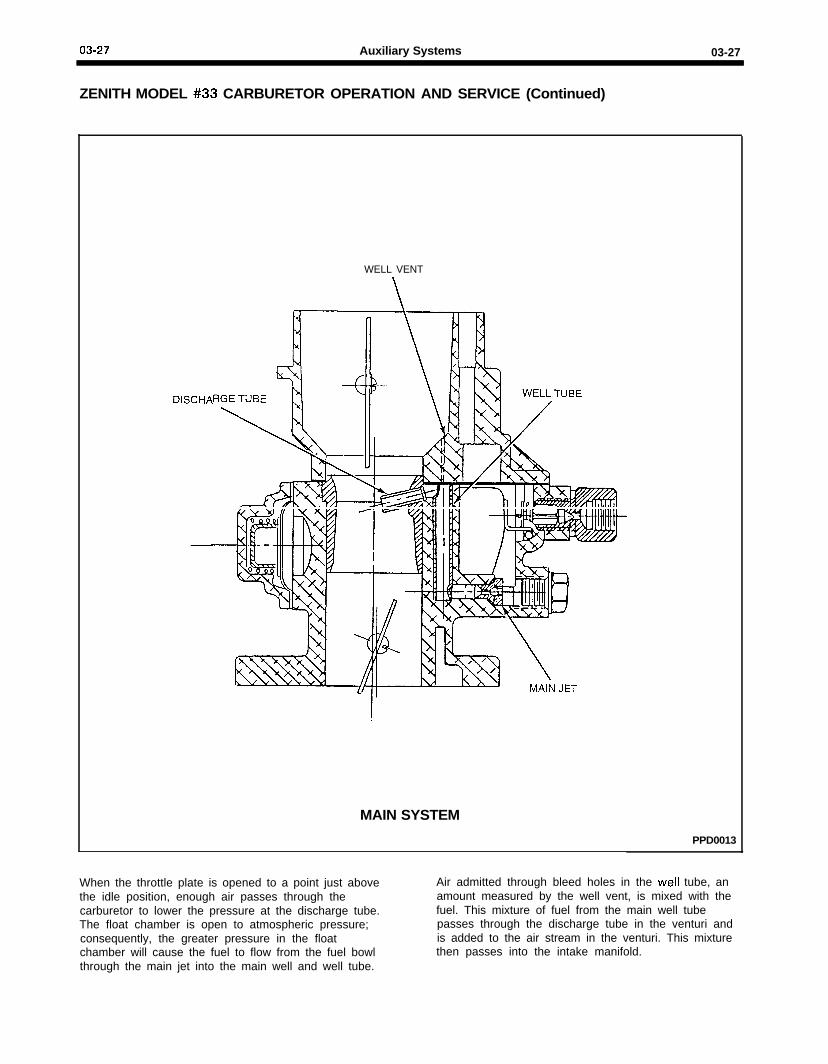
03-27 Auxiliary Systems 03-27
ZENITH MODEL #33 CARBURETOR OPERATION AND SERVICE (Continued)
DISCHA
WELL VENT
MAIN SYSTEM
PPD0013
When the throttle plate is opened to a point just abovethe idle position, enough air passes through thecarburetor to lower the pressure at the discharge tube.The float chamber is open to atmospheric pressure;consequently, the greater pressure in the floatchamber will cause the fuel to flow from the fuel bowlthrough the main jet into the main well and well tube.
Air admitted through bleed holes in the well tube, anamount measured by the well vent, is mixed with thefuel. This mixture of fuel from the main well tubepasses through the discharge tube in the venturi andis added to the air stream in the venturi. This mixturethen passes into the intake manifold.

03-28 Auxiliary Systems 03-28
ZENITH MODEL #33 CARBURETOR OPERATION AND SERVICE (Continued)
Accelerating Pump System
The accelerating pump controls the amount of fuel that is discharged into the air stream on sudden throttle openings. When the throttle is opened suddenly, air rushes through the carburetor into the intake manifold and to the engine. This air is lighter than the liquid fuel and gets into motion more quickly. That means that the air reaches the cylinders of the engine before the first charge of fuel supplied by the high speed system. A lean mixture would result momentarily in this case, and to counteract the condition, additional fuel must be supplied instantly. The supply of that extra fuel is the job of the accelerating pump system.
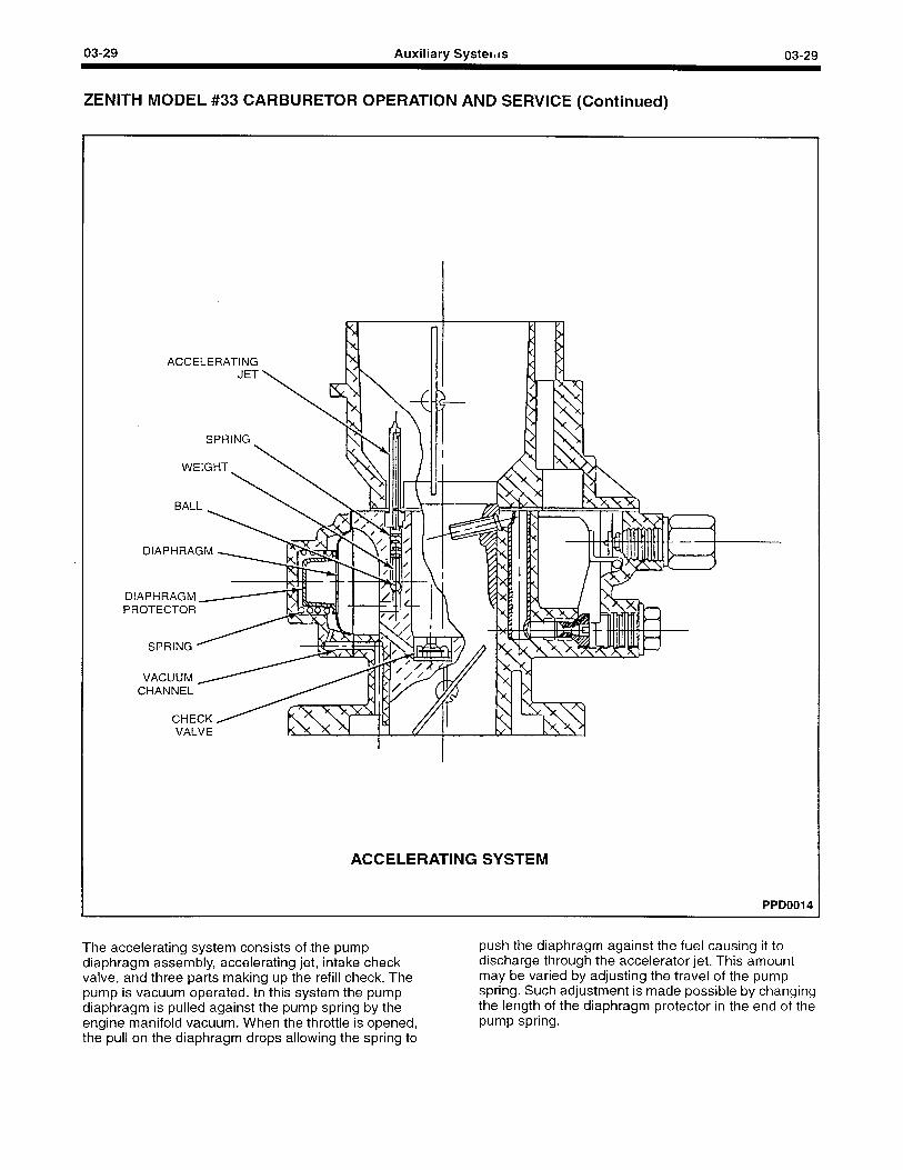
03-29 Auxiliary Systems 03-29
ZENITH MODEL #33 CARBURETOR OPERATION AND SERVICE (Continued)
ACCELERATING
DIAPHRAGM
PROTECTOR
VALVE I
I
ACCELERATING SYSTEM
PPD0014
The accelerating system consists of the pump diaphragm assembly, accelerating jet, intake check valve, and three parts making up the refill check. The pump is vacuum operated. In this system the pump diaphragm is pulled against the pump spring by the engine manifold vacuum. When the throttle is opened, the pull on the diaphragm drops allowing the spring to
push the diaphragm against the fuel causing it to discharge through the accelerator jet. This amount may be varied by adjusting the travel of the pump spring. Such adjustment is made possible by changing the length of the diaphragm protector in the end of the pump spring.
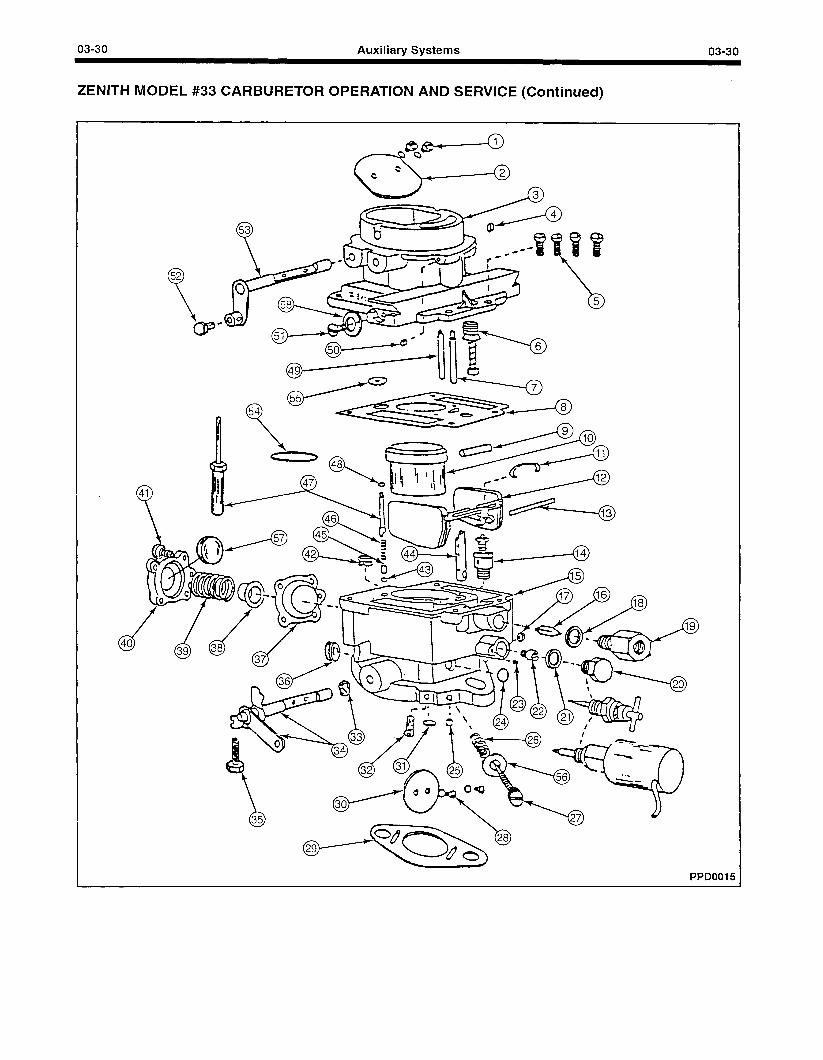
03-30 Auxiliary Systems 03-30
ZENITH MODEL #33 CARBURETOR OPERATION AND SERVICE (Continued)
52 Y BP
#
-0 6
PPD0015
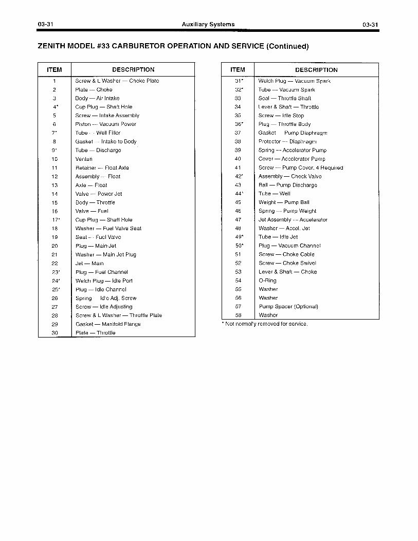
03-31 Auxiliary Systems 03-31
ZENITH MODEL #33 CARBURETOR OPERATION AND SERVICE (Continued)
ITEM DESCRIPTION
1 Screw & L Washer - Choke Plate
2 Plate - Choke
3 Body - Air Intake
4” Cup Plug - Shaft Hole
5 Screw - Intake Assembly
6 Piston - Vacuum Power
7” Tube - Well Filler
8 Gasket - Intake to Body
9” Tube - Discharge
10 Venturi
11 Retainer - Float Axle
12 Assembly - Float
13 Axle - Float
14 Valve - Power Jet
15 Body - Throttle
16 Valve - Fuel
17” Cup Plug - Shaft Hole
18 Washer - Fuel Valve Seat
19 Seat - Fuel Valve
20 Plug - Main Jet
21 Washer - Main Jet Plug
22 Jet - Main
23” Plug - Fuel Channel
24” Welch Plug - Idle Port
25” Plug - Idle Channel
26 Spring - Idle Adj. Screw
27 Screw - Idle Adjusting
28 Screw & L Washer - Throttle Plate
29 Gasket - Manifold Flange
30 Plate - Throttle
ITEM DESCRIPTION
31* Welch Plug - Vacuum Spark
32* Tube - Vacuum Spark
33 Seal - Throttle Shaft
34 Lever & Shaft - Throttle
35 Screw - Idle Stop
36” Plug - Throttle Body
37 Gasket - Pump Diaphragm
38 Protector - Diaphragm
39 Spring -Accelerator Pump
40 Cover - Accelerator Pump
41 Screw - Pump Cover, 4 Required
42” Assembly - Check Valve
43 Ball - Pump Discharge
44” Tube - Well
45 Weight - Pump Ball
46 Spring - Pump Weight
47 Jet Assembly - Accelerator
48 Washer - Accel. Jet
49” Tube - Idle Jet
50* Plug - Vacuum Channel
51 Screw - Choke Cable
52 Screw - Choke Swivel
53 Lever & Shaft - Choke
54 O-Ring
55 Washer
56 Washer
57 Pump Spacer (Optional)
58 Washer
* Not normally removed for service.
03-32 Auxiliary Systems 03-32
ZENITH MODEL #33 CARBURETOR OPERATION AND SERVICE (Continued)
Disassembly Disassembly consists of separating the carburetor into two basic groups: air intake and fuel bowl-throttle body and the disassembly of each of these groups. Use exploded illustration as a guide for disassembly and reassembly.
Cleaning and Inspection Thoroughly clean all metal parts in solvent or Deepclene. Blow out all parts and channels with air pressure. Inspect for damage, excessive wear, burrs or warpage. DO NOT CLEAN NON-METALLIC PARTS in solvent or Deepclene.
NOTE: The following assembly instructions and the exploded illustration are generalized and include all parts possibly found in the carburetor at this time. Therefore, atl of the parts shown and mentioned may not be included in the particular assembly being worked on.
Assembly Of Air Intake 1. Drive channel plug (50) into vacuum channel
flush with surface.
2. Drive cup plug (4) into end of choke shaft hole opposite choke lever.
3. Insert choke shaft (53) with milled flat toward top.
4. ’ Install choke plate (2) in air intake and start screws (1). Note that edges are beveled to fit against wall when closed. On plates including poppet valve, the spring should face the top. Hold choke plate closed with finger and tighten screws.
5. Turn air intake upside down and insert vacuum power piston (6) into cylinder, making sure it will move freely. Hold in place and stake casting with punch at three points to retain piston assembly.
6. Press well filler tube (7) into casting to shoulder. Do not bend or distort.
7. Press idle tube (49) into casting with rolled down orifice into casting until the bottom end is 1.25 inches from the cast surface. Do not bend or distort.
Assembly Of Fuel Bowl 1. Install the following parts as needed (not normally
removed for service):
a. Cup plug (17) in shaft hole flush
b. Fuel channel plug (23) flush
c. Welch plug (24) over idle port
d. Idle channel plug (25) flush
e. Welch plug (31) over spark vacuum port
f. Spark vacuum tube (32) to approximately 9/l 6 from casting
g. Throttle body plug (36) flush
h. Pump check valve (42) flush using tool c151-53.
2.
3.
4.
5.
6.
7.
8.
9.
10.
11.
12.
13.
14.
i. Well tube (44) making sure that end openings align with notch in casting at top and fuel channel at bottom.
Slide seal (33) over throttle shaft with lip toward lever and install shaft in body.
Back out throttle stop screw (35) and place body on bench with mounting flange up.
With milled flat up, install throttle plate (30) with short side toward idle port and start screws (28). Make sure beveled sides of plate are next to throttle body bore. Tap the plate lightly (plate held closed) to center it and tighten screws.
While holding throttle closed, screw idle stop screw (35) in until it touches the casting, then screw in an additional 3/4 turn.
Install idle needle (27) washer (56) and spring (26) and screw in to gently touch the seat. Back screw out approximately one turn.
Install power jet valve (14) using Cl 61-9 wrench. No gasket required.
Install main jet (22) and seat firmly with screwdriver. No gasket required.
Install main jet plug (20) and washer (21) and tighten securely. If main jet adjustment or solenoid shutoff are used, install in place of plug.
Turn body right side up. Insert float axle (13) into holes in float (12).
Lower float axle and float into slot provided in body with the float needle sticking into the threaded opening.
Install the fuel valve seat (19) and washer (18) making sure that the fuel valve enters the seat properly (the valve will enter the seat more easily if the float is heid in the up position) and tighten securely.
Insert float axle clip (11) in slot to bear against axle ends. Holding axle in place, raise float by applying light finger pressure to the float bracket. Float pontoons should be approximately level when the valve is seated. If not, bend tab carefully to adjust.
Install O-ring (54) on venturi skirt and place venturi (10) into recess provided in body making sure that the nozzle (9) lines up with the notch in the fuel well.
03-33 Auxiliary Systems 03-33
ZENITH MODEL #33 CARBURETOR OPERATION AND SERVICE (Continued)
15
16
17
Place intake gasket (8) in position on body. Note: if you have an older model unit with removable accelerator jet; after intake gasket (8) is in place, an additional washer (55) will be assembled over the accelerator jet tube (47) and set inside the large hole in the intake gasket (8) and on top of the smaller washer (48). Lower air intake carefully onto bowl and fasten securely and evenly using attaching screws (5).
Place accelerator pump diaphragm (37) in place on body with bagged section into cavity. Insert diaphragm protector (38) into end of spring (39) and install spring with protector against diaphragm.
Place cover (40) over spring and compress. Insert screws (41) and tighten evenly and securely. Note: Pump spacer (57) will install into cover before assembly if required.
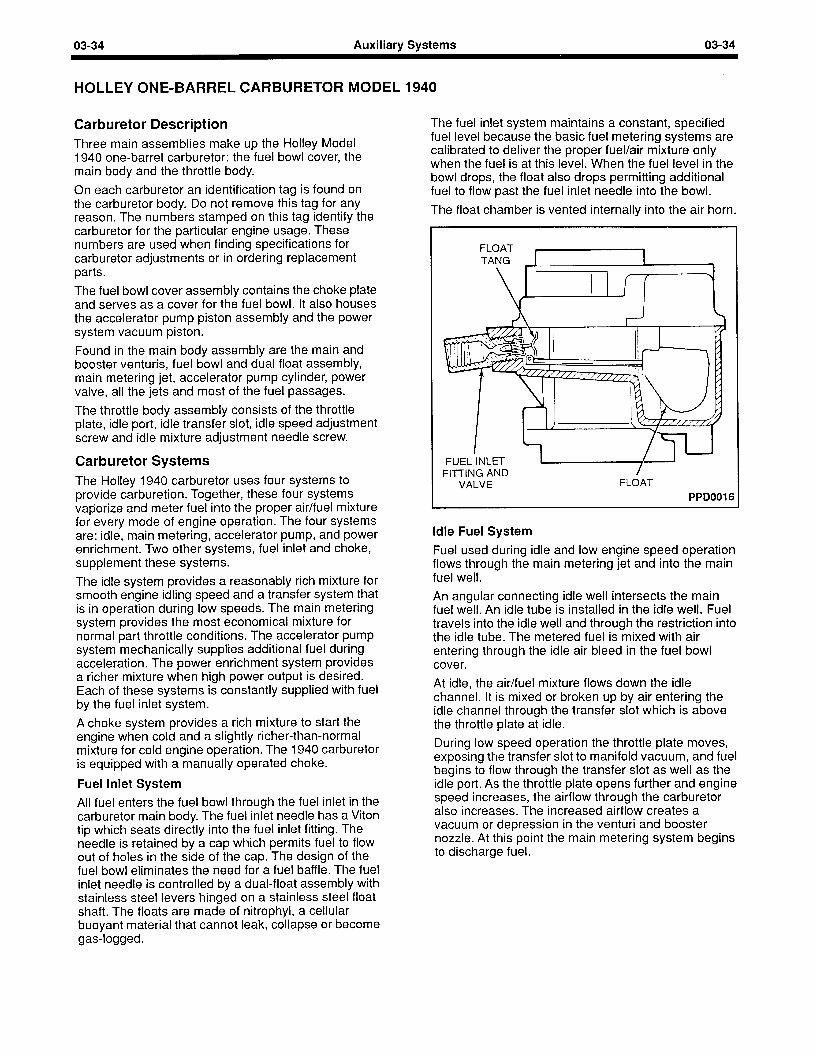
03-34 Auxiliary Systems 03-34
HOLLEY ONE-BARREL CARBURETOR MODEL 1940
Carburetor Description Three main assemblies make up the Halley Model 1940 one-barrel carburetor: the fuel bowl cover, the main body and the throttle body.
On each carburetor an identification tag is found on the carburetor body. Do not remove this tag for any reason. The numbers stamped on this tag identify the carburetor for the particular engine usage. These numbers are used when finding specifications for carburetor adjustments or in ordering replacement parts.
The fuel bowl cover assembly contains the choke plate and serves as a cover for the fuel bowl. It also houses the accelerator pump piston assembly and the power system vacuum piston.
Found in the main body assembly are the main and booster venturis, fuel bowl and dual float assembly, main metering jet, accelerator pump cylinder, power valve, all the jets and most of the fuel passages.
The throttle body assembly consists of the throttle plate, idle port, idle transfer slot, idle speed adjustment screw and idle mixture adjustment needle screw.
Carburetor Systems The Holley 1940 carburetor uses four systems to provide carburetion. Together, these four systems vaporize and meter fuel into the proper air/fuel mixture for every mode of engine operation. The four systems are: idle, main metering, accelerator pump, and power enrichment. Two other systems, fuel inlet and choke, supplement these systems.
The idle system provides a reasonably rich mixture for smooth engine idling speed and a transfer system that is in operation during low speeds. The main metering system provides the most economical mixture for normal part throttle conditions. The accelerator pump system mechanically supplies additional fuel during acceleration. The power enrichment system provides a richer mixture when high power output is desired. Each of these systems is constantly supplied with fuel by the fuel inlet system.
A choke system provides a rich mixture to start the engine when cold and a slightly richer-than-normal mixture for cold engine operation. The 1940 carburetor is equipped with a manually operated choke.
Fuel Inlet System
All fuel enters the fuel bowl through the fuel inlet in the carburetor main body. The fuel inlet needle has a Viton tip which seats directly into the fuel inlet fitting. The needle is retained by a cap which permits fuel to flow out of holes in the side of the cap. The design of the fuel bowl eliminates the need for a fuel baffle. The fuel inlet needle is controlled by a dual-float assembly with stainless steel levers hinged on a stainless steel float shaft. The floats are made of nitrophyl, a cellular buoyant material that cannot leak, collapse or become gas-logged.
The fuel inlet system maintains a constant, specified fuel level because the basic fuel metering systems are calibrated to deliver the proper fuel/air mixture only when the fuel is at this level. When the fuel level in the bowl drops, the float also drops permitting additional fuel to flow past the fuel inlet needle into the bowl.
The float chamber is vented internally into the air horn.
FLOAT t 1 TANG 1 1
’ IT FUEL INLET FI-ITING AND /
VALVE FLOAT
PPDOOI 6
Idle Fuel System
Fuel used during idle and low engine speed operation flows through the main metering jet and into the main fuel well.
An angular connecting idle well intersects the main fuel well. An idle tube is installed in the idle well. Fuel travels into the idle well and through the restriction into the idle tube. The metered fuel is mixed with air entering through the idle air bleed in the fuel bowl cover.
At idle, the air/fuel mixture flows down the idle channel. It is mixed or broken up by air entering the idle channel through the transfer slot which is above the throttle plate at idle.
During low speed operation the throttle plate moves, exposing the transfer slot to manifold vacuum, and fuel begins to flow through the transfer slot as well as the idle port. As the throttle plate opens further and engine speed increases, the airflow through the carburetor also increases. The increased airflow creates a vacuum or depression in the venturi and booster nozzle. At this point the main metering system begins to discharge fuel.
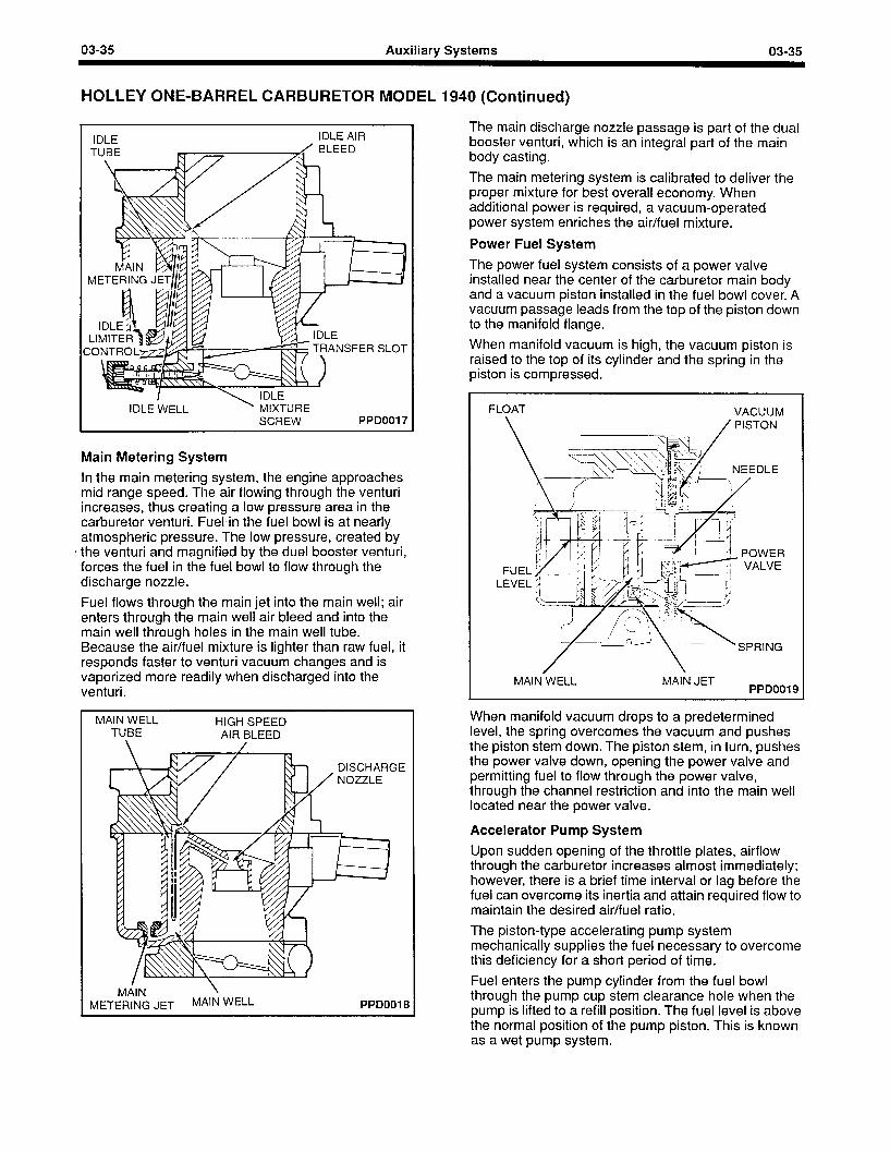
03-35 Auxiliary Systems 03-35
HOLLEY ONE-BARREL CARBURETOR MODEL 1930 (Continued)
Inr c IDLE AIR
IDLE WELL ’ MIXTURE SCREW PPD0017
Main Metering System
In the main metering system, the engine approaches mid range speed. The air flowing through the venturi increases, thus creating a low pressure area in the carburetor venturi. Fuel in the fuel bowl is at nearly atmospheric pressure. The low pressure, created by
8 the venturi and magnified by the duel booster venturi, forces the fuel in the fuel bowl to flow through the discharge nozzle.
Fuel flows through the main jet into the main well; air enters through the main well air bleed and into the main well through holes in the main well tube. Because the air/fuel mixture is lighter than raw fuel, it responds faster to venturi vacuum changes and is vaporized more readily when discharged into the venturi.
I MAIN WELL HIGH SPEED TUBE AIR BLEED
DISCHARGE
I MAIN \
METERING JET MAIN WELL PPDOOI 8
The main discharge nozzle passage is part of the dual booster venturi, which is an integral part of the main body casting.
The main metering system is calibrated to deliver the proper mixture for best overall economy. When additional power is required, a vacuum-operated power system enriches the air/fuel mixture.
Power Fuel System
The power fuel system consists of a power valve installed near the center of the carburetor main body and a vacuum piston installed in the fuel bowl cover. A vacuum passage leads from the top of the piston down to the manifold flange.
When manifold vacuum is high, the vacuum piston is raised to the top of its cylinder and the spring in the piston is compressed.
FLOAT
\
VACUUM / PISTON
MAIN WELL MAIN JET PPDOOI 9
When manifold vacuum drops to a predetermined level, the spring overcomes the vacuum and pushes the piston stem down. The piston stem, in turn, pushes the power valve down, opening the power valve and permitting fuel to flow through the power valve, through the channel restriction and into the main well located near the power valve.
Accelerator Pump System
Upon sudden opening of the throttle plates, airflow through the carburetor increases almost immediately; however, there is a brief time interval or lag before the fuel can overcome its inertia and attain required flow to maintain the desired air/fuel ratio.
The piston-type accelerating pump system mechanically supplies the fuel necessary to overcome this deficiency for a short period of time.
Fuel enters the pump cylinder from the fuel bowl through the pump cup stem clearance hole when the pump is lifted to a refill position. The fuel level is above the normal position of the pump piston. This is known as a wet pump system.
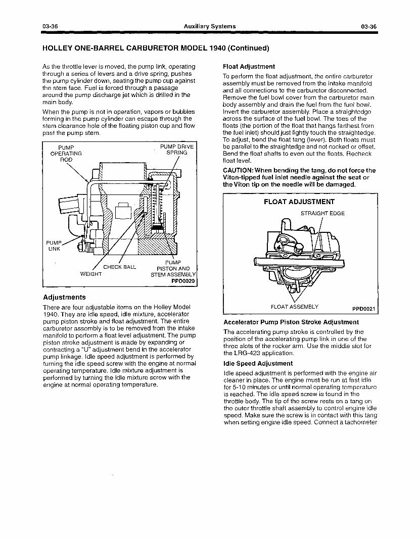
03-36 Auxiliary Systems 03-36
HOLLEY ONE-BARREL CARBURETOR MODEL 1940 (Continued)
As the throttle lever is moved, the pump link, operating through a series of levers and a drive spring, pushes the pump cylinder down, seating the pump cup against the stem face. Fuel is forced through a passage around the pump discharge jet which is drilled in the main body.
When the pump is not in operation, vapors or bubbles forming in the pump cylinder can escape through the stem clearance hole of the floating piston cup and flow past the pump stem.
PUMP OPERATING
ROD
PUMP DRIVE SPRING
/
PUMP/ LINK
/ /
CHECK BALL WEIGHT
PUMP PISTON AND
STEM ASSEMBLY PPD0020
Adjustments
There are four adjustable items on the Holley Model 1940. They are idle speed, idle mixture, accelerator pump piston stroke and float adjustment. The entire carburetor assembly is to be removed from the intake manifold to perform a float level adjustment. The pump piston stroke adjustment is made by expanding or contracting a “U” adjustment bend in the accelerator pump linkage. Idle speed adjustment is performed by turning the idle speed screw with the engine at normal operating temperature. Idle mixture adjustment is performed by turning the idle mixture screw with the engine at normal operating temperature.
Float Adjustment
To perform the float adjustment, the entire carburetor assembly must be removed from the intake manifold and all connections to the carburetor disconnected. Remove the fuel bowl cover from the carburetor main body assembly and drain the fuel from the fuel bowl. Invert the carburetor assembly. Place a straightedge across the surface of the fuel bowl. The toes of the floats (the portion of the float that hangs farthest from the fuel inlet) should just lightly touch the straightedge. To adjust, bend the float tang (lever). Both floats must be parallel to the straightedge and not cocked or offset. Bend the float shafts to even out the floats. Recheck float level.
CAUTION: When bending the tang, do not force the Viton-tipped fuel inlet needle against the seat or theviton tip on the needle will be damaged.
FLOAT ADJUSTMENT
STRAIGHT EDGE
FLOAT ASSEMBLY PPD0021
Accelerator Pump Piston Stroke Adjustment
The accelerating pump stroke is controlled by the position of the accelerating pump link in one of the three slots of the rocker arm. Use the middle slot for the LRG-423 application.
Idle Speed Adjustment
Idle speed adjustment is performed with the engine air cleaner in place. The engine must be run at fast idle for 5-I 0 minutes or until normal operating temperature is reached. The idle speed screw is found in the throttle body. The tip of the screw rests on a tang on the outer throttle shaft assembly to control engine idle speed. Make sure the screw is in contact with this tang when setting engine idle speed. Connect a tachometer
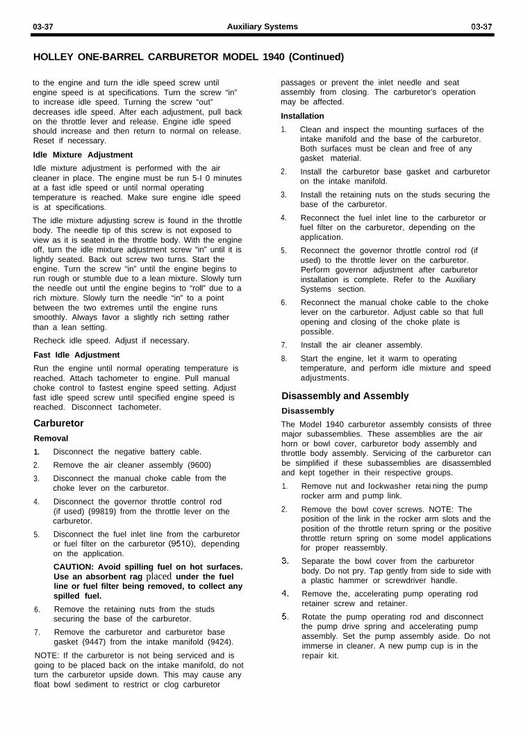
03-37 Auxiliary Systems 03-37
HOLLEY ONE-BARREL CARBURETOR MODEL 1940 (Continued)
to the engine and turn the idle speed screw untilengine speed is at specifications. Turn the screw “in”to increase idle speed. Turning the screw “out”decreases idle speed. After each adjustment, pull backon the throttle lever and release. Engine idle speedshould increase and then return to normal on release.Reset if necessary.
Idle Mixture Adjustment
Idle mixture adjustment is performed with the aircleaner in place. The engine must be run 5-I 0 minutesat a fast idle speed or until normal operatingtemperature is reached. Make sure engine idle speedis at specifications.
The idle mixture adjusting screw is found in the throttlebody. The needle tip of this screw is not exposed toview as it is seated in the throttle body. With the engineoff, turn the idle mixture adjustment screw “in” until it islightly seated. Back out screw two turns. Start theengine. Turn the screw “in” until the engine begins torun rough or stumble due to a lean mixture. Slowly turnthe needle out until the engine begins to “roll” due to arich mixture. Slowly turn the needle “in” to a pointbetween the two extremes until the engine runssmoothly. Always favor a slightly rich setting ratherthan a lean setting.
Recheck idle speed. Adjust if necessary.
Fast Idle Adjustment
Run the engine until normal operating temperature isreached. Attach tachometer to engine. Pull manualchoke control to fastest engine speed setting. Adjustfast idle speed screw until specified engine speed isreached. Disconnect tachometer.
CarburetorRemoval
1. Disconnect the negative battery cable.
2. Remove the air cleaner assembly (9600)
3. Disconnect the manual choke cable fromchoke lever on the carburetor.
the
4. Disconnect the governor throttle control rod(if used) (99819) from the throttle lever on thecarburetor.
5. Disconnect the fuel inlet line from the carburetoror fuel filter on the carburetor (9510), dependingon the application.
CAUTION: Avoid spilling fuel on hot surfaces.Use an absorbent rag placed under the fuelline or fuel filter being removed, to collect anyspilled fuel.
6. Remove the retaining nuts from the studssecuring the base of the carburetor.
7. Remove the carburetor and carburetor basegasket (9447) from the intake manifold (9424).
NOTE: If the carburetor is not being serviced and isgoing to be placed back on the intake manifold, do notturn the carburetor upside down. This may cause anyfloat bowl sediment to restrict or clog carburetor
passages or prevent the inlet needle and seatassembly from closing. The carburetor’s operationmay be affected.
Installation
1.
2.
3.
4.
5.
6.
7.
8.
Clean and inspect the mounting surfaces of theintake manifold and the base of the carburetor.Both surfaces must be clean and free of anygasket material.
Install the carburetor base gasket and carburetoron the intake manifold.
Install the retaining nuts on the studs securing thebase of the carburetor.
Reconnect the fuel inlet line to the carburetor orfuel filter on the carburetor, depending on theapplication.
Reconnect the governor throttle control rod (ifused) to the throttle lever on the carburetor.Perform governor adjustment after carburetorinstallation is complete. Refer to the AuxiliarySystems section.
Reconnect the manual choke cable to the chokelever on the carburetor. Adjust cable so that fullopening and closing of the choke plate ispossible.
Install the air cleaner assembly.
Start the engine, let it warm to operatingtemperature, and perform idle mixture and speedadjustments.
Disassembly and AssemblyDisassembly
The Model 1940 carburetor assembly consists of threemajor subassemblies. These assemblies are the airhorn or bowl cover, carburetor body assembly andthrottle body assembly. Servicing of the carburetor canbe simplified if these subassemblies are disassembledand kept together in their respective groups.
1.
2.
Remove nut and lockwasherrocker arm and pump link.
retai ning the pump
Remove the bowl cover screws. NOTE: Theposition of the link in the rocker arm slots and theposition of the throttle return spring or the positivethrottle return spring on some model applicationsfor proper reassembly.
Separate the bowl cover from the carburetorbody. Do not pry. Tap gently from side to side witha plastic hammer or screwdriver handle.
Remove the, accelerating pump operating rodretainer screw and retainer.
Rotate the pump operating rod and disconnectthe pump drive spring and accelerating pumpassembly. Set the pump assembly aside. Do notimmerse in cleaner. A new pump cup is in therepair kit.
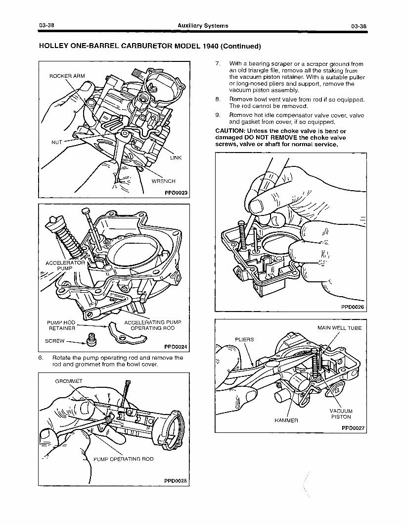
03-38 Auxiliary Systems 03-38
HOLLEY ONE-BARREL CARBURETOR MODEL 1940 (Continued)
PPD0023
RETAINER -
SCREw 4 ppDOO24
6. Rotate the pump operating rod and remove the rod and grommet from the bowl cover.
PUMP OPERATING ROD
PPD3025
7. With a bearing scraper or a scraper ground from an old triangle file, remove all the staking from the vacuum piston retainer. With a suitable puller or long-nosed pliers and support, remove the vacuum piston assembly.
8. Remove bowl vent valve from rod if so equipped. The rod cannot be removed.
9. Remove hot idle compensator valve cover, valve and gasket from cover, if so equipped.
CAUTION: Unless the choke valve is bent or damaged DO NOT REMOVE the choke valve screws, valve or shaft for normal service.
PPDO026
HAMMER
PPD0027
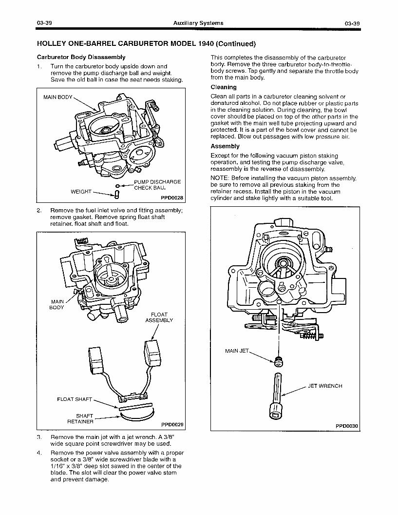
03-39 Auxiliary Systems 03-39
HOLLEY ONE-BARREL CARBURETOR MODEL 1940 (Continued)
Carburetor Body Disassembly
1. Turn the carburetor body upside down and remove the pump discharge ball and weight. Save the old ball in case the seat needs staking.
- PUMP DISCHARGE
WEIGHT y-CHECK BA;pDoo28
2. Remove the fuel inlet valve and fitting assembly; remove gasket. Remove spring float shaft retainer, float shaft and float.
MA BOII
FLOAT SSEMBLY
FLOAT SHAFT
11
RETAINER PPD0029
This completes the disassembly of the carburetor body. Remove the three carburetor body-to-throttle- body screws. Tap gently and separate the throttle body from the main body.
Cleaning
Clean all parts in a carburetor cleaning solvent or denatured alcohol. Do not place rubber or plastic parts in the cleaning solution. During cleaning, the bowl cover should be placed on top of the other parts in the gasket with the main well tube projecting upward and protected. It is a part of the bowl cover and cannot be replaced. Blow out passages with low pressure air.
Assembly
Except for the following vacuum piston staking operation, and testing the pump discharge valve, reassembly is the reverse of disassembly.
NOTE: Before installing the vacuum piston assembly, be sure to remove all previous staking from the retainer recess. Install the piston in the vacuum cylinder and stake lightly with a suitable tool.
MAIN JET
4
3. Remove the main jet with a jet wrench. A 3/8” wide square point screwdriver may be used.
JET WRENCH
PPD0030
4. Remove the power valve assembly with a proper socket or a 3/8” wide screwdriver blade with a 1 /I 6” x 3/8” deep slot sawed in the center of the blade. The slot will clear the power valve stem and prevent damage.
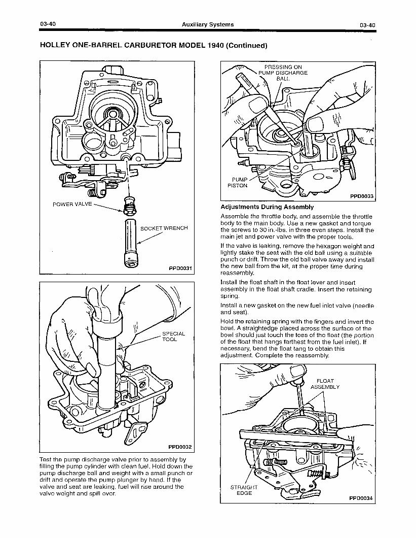
03-40 Auxiliary Systems 03-40
HOLLEY ONE-BARREL CARBURETOR MODEL 1940 (Continued)
POWER VALVE
SOCKET WRENCH
PPD0031
PPD0032
Test the pump discharge valve prior to assembly by filling the pump cylinder with clean fuel. Hold down the pump discharge ball and weight with a small punch or drift and operate the pump plunger by hand. If the valve and seat are leaking, fuel will rise around the valve weight and spill over.
Adjustments During Assembly
Assemble the throttle body, and assemble the throttle body to the main body. Use a new gasket and torque the screws to 30 in.-lbs. in three even steps. Install the main jet and power valve with the proper tools.
If the valve is leaking, remove the hexagon weight and lightly stake the seat with the old ball using a suitable punch or drift. Throw the old ball valve away and install the new ball from the kit, at the proper time during reassembly.
Install the float shaft in the float lever and insert assembly in the float shaft cradle. Insert the retaining spring.
Install a new gasket on the new fuel inlet valve (needle and seat).
Hold the retaining spring with the fingers and invert the bowl. A straightedge placed across the surface of the bowl should just touch the toes of the float (the portion of the float that hangs farthest from the fuel inlet). If necessary, bend the float tang to obtain this adjustment. Complete the reassembly.
ASSEMBLY
PPD0034
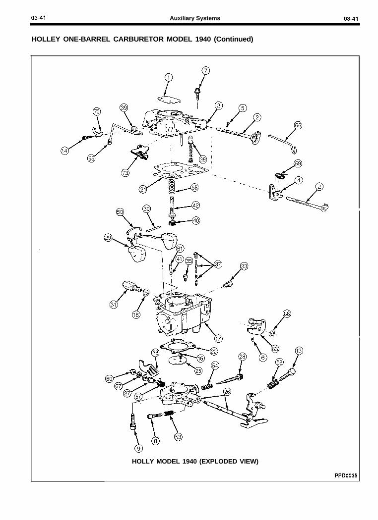
03-41 Auxiliary Systems 03-41
HOLLEY ONE-BARREL CARBURETOR MODEL 1940 (Continued)
HOLLY MODEL 1940 (EXPLODED VIEW)
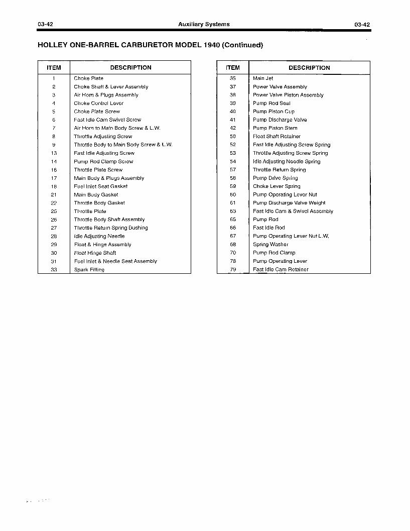
03-42 Auxiliary Systems 03-42
HOLLEY ONE-BARREL CARBURETOR MODEL 1940 (Continued)
ITEM DESCRIPTION
1 Choke Plate
2 Choke Shaft & Lever Assembly
3 Air Horn & Plugs Assembly
4 Choke Control Lever
5 Choke Plate Screw
6 Fast Idle Cam Swivel Screw
7 Air Horn to Main Body Screw & L.W.
8 Throttle Adjusting Screw
9 Throttle Body to Main Body Screw & L.W.
13 Fast Idle Adjusting Screw
14 Pump Rod Clamp Screw
16 Throttle Plate Screw
17 Main Body & Plugs Assembly
18 Fuel Inlet Seat Gasket
21 Main Body Gasket
22 Throttle Body Gasket
25 Throttle Plate
26 Throttle Body Shaft Assembly
27 Throttle Return Spring Bushing
28 Idle Adjusting Needle
29 Float & Hinge Assembly
‘30 Float Hinge Shaft
31 Fuel Inlet & Needle Seat Assembly
33 Spark Fitting
ITEM DESCRIPTION
35 Main Jet
37 Power Valve Assembly
38 Power Valve Piston Assembly
39 Pump Rod Seal
40 Pump Piston Cup
41 Pump Discharge Valve
42 Pump Piston Stem
50 Float Shaft Retainer
52 Fast Idle Adjusting Screw Spring
53 Throttle Adjusting Screw Spring
54 Idle Adjusting Needle Spring
57 Throttle Return Spring
58 Pump Drive Spring
59 Choke Lever Spring
60 Pump Operating Lever Nut
61 Pump Discharge Valve Weight
63 Fast Idle Cam & Swivel Assembly
65 Pump Rod
66 Fast Idle Rod
67 Pump Operating Lever Nut L.W.
68 Spring Washer
70 Pump Rod Clamp
78 Pump Operating Lever
79 Fast Idle Cam Retainer
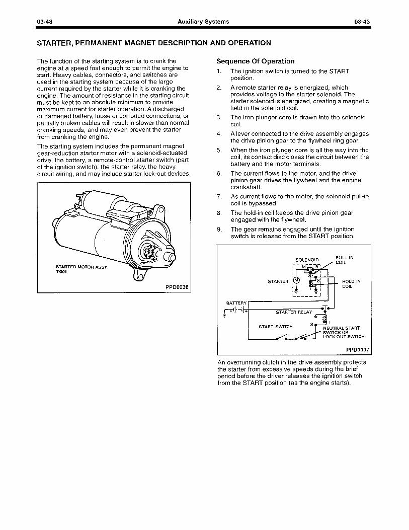
03-43 Auxiliary Systems 03-43
STARTER, PERMANENT MAGNET DESCRIPTION AND OPERATION
The function of the starting system is to crank the engine at a speed fast enough to permit the engine to start. Heavy cables, connectors, and switches are used in the starting system because of the large current required by the starter while it is cranking the engine. The amount of resistance in the starting circuit must be kept to an absolute minimum to provide maximum current for starter operation. A discharged or damaged battery, loose or corroded connections, or partially broken cables will result in slower than normal cranking speeds, and may even prevent the starter from cranking the engine.
The starting system includes the permanent magnet gear-reduction starter motor with a solenoid-actuated drive, the battery, a remote-control starter switch (part of the ignition switch), the starter relay, the heavy circuit wiring, and may include starter lock-out devices.
STARTER MOTOR ASSY I) / w
PPD0036
Sequence Of Operation 1. The ignition switch is turned to the START
position.
2. A remote starter relay is energized, which provides voltage to the starter solenoid. The starter solenoid is energized, creating a magnetic field in the solenoid coil.
3. The iron plunger core is drawn into the solenoid coil.
4. A lever connected to the drive assembly engages the drive pinion gear to the flywheel ring gear.
5. When the iron plunger core is all the way into the coil, its contact disc closes the circuit between the battery and the motor terminals.
6. The current flows to the motor, and the drive pinion gear drives the flywheel and the engine crankshaft.
7. As current flows to the motor, the solenoid pull-in coil is bypassed.
8. The hold-in coil keeps the drive pinion gear engaged with the flywheel.
9. The gear remains engaged until the ignition switch is released from the START position.
STARTER
w-
it+ STARTER RELAY 5
PPD0037
An overrunning clutch in the drive assembly protects the starter from excessive speeds during the brief period before the driver releases the ignition switch from the START position (as the engine starts).
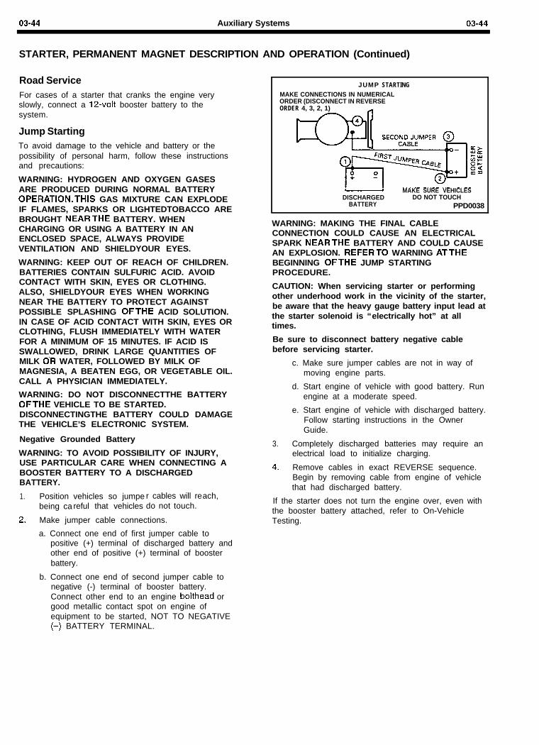
03-44 Auxiliary Systems 03-44
STARTER, PERMANENT MAGNET DESCRIPTION AND OPERATION (Continued)
Road ServiceFor cases of a starter that cranks the engine veryslowly, connect a 12-volt booster battery to thesystem.
Jump StartingTo avoid damage to the vehicle and battery or thepossibility of personal harm, follow these instructionsand precautions:
WARNING: HYDROGEN AND OXYGEN GASESARE PRODUCED DURING NORMAL BATTERYOPERATION.THlS GAS MIXTURE CAN EXPLODEIF FLAMES, SPARKS OR LIGHTEDTOBACCO AREBROUGHT NEARTHE BATTERY. WHENCHARGING OR USING A BATTERY IN ANENCLOSED SPACE, ALWAYS PROVIDEVENTILATION AND SHIELDYOUR EYES.
WARNING: KEEP OUT OF REACH OF CHILDREN.BATTERIES CONTAIN SULFURIC ACID. AVOIDCONTACT WITH SKIN, EYES OR CLOTHING.ALSO, SHIELDYOUR EYES WHEN WORKINGNEAR THE BATTERY TO PROTECT AGAINSTPOSSIBLE SPLASHING OFTHE ACID SOLUTION.IN CASE OF ACID CONTACT WITH SKIN, EYES ORCLOTHING, FLUSH IMMEDIATELY WITH WATERFOR A MINIMUM OF 15 MINUTES. IF ACID ISSWALLOWED, DRINK LARGE QUANTITIES OFMILK O’R WATER, FOLLOWED BY MILK OFMAGNESIA, A BEATEN EGG, OR VEGETABLE OIL.CALL A PHYSICIAN IMMEDIATELY.
WARNING: DO NOT DISCONNECTTHE BATTERYOFTHE VEHICLE TO BE STARTED.DISCONNECTINGTHE BATTERY COULD DAMAGETHE VEHICLE’S ELECTRONIC SYSTEM.
Negative Grounded Battery
WARNING: TO AVOID POSSIBILITY OF INJURY,USE PARTICULAR CARE WHEN CONNECTING ABOOSTER BATTERY TO A DISCHARGEDBATTERY.
1.
2.
Position vehicles so jumpe r cables will rebeing ca reful that vehicles do not touch.
Make jumper cable connections.
a. Connect one end of first jumper cable topositive (+) terminal of discharged battery andother end of positive (+) terminal of boosterbattery.
ach,
b. Connect one end of second jumper cable tonegative (-) terminal of booster battery.Connect other end to an engine bolthead orgood metallic contact spot on engine ofequipment to be started, NOT TO NEGATIVE(-) BATTERY TERMINAL.
JUMP STARTINGMAKE CONNECTIONS IN NUMERICALORDER (DISCONNECT IN REVERSEORDER 4, 3, 2, 1)
MAKE SURE VEHICLESDISCHARGED DO NOT TOUCH
BATTERY PPD0038
WARNING: MAKING THE FINAL CABLECONNECTION COULD CAUSE AN ELECTRICALSPARK NEARTHE BATTERY AND COULD CAUSEAN EXPLOSION. REFERTO WARNING ATTHEBEGINNING OFTHE JUMP STARTINGPROCEDURE.
CAUTION: When servicing starter or performingother underhood work in the vicinity of the starter,be aware that the heavy gauge battery input lead atthe starter solenoid is “electrically hot” at alltimes.
Be sure to disconnect battery negative cablebefore servicing starter.
c. Make sure jumper cables are not in way ofmoving engine parts.
d. Start engine of vehicle with good battery. Runengine at a moderate speed.
e. Start engine of vehicle with discharged battery.Follow starting instructions in the OwnerGuide.
3. Completely discharged batteries may require anelectrical load to initialize charging.
4. Remove cables in exact REVERSE sequence.Begin by removing cable from engine of vehiclethat had discharged battery.
If the starter does not turn the engine over, even withthe booster battery attached, refer to On-VehicleTesting.
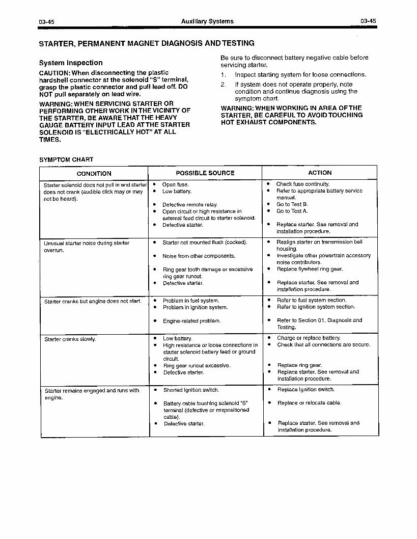
03-45 Auxiliary Systems 03-45
STARTER, PERMANENT MAGNET DIAGNOSIS ANDTESTING
System Inspection CAUTION: When disconnecting the plastic hardshell connector at the solenoid “9 terminal, grasp the plastic connector and pull lead off. DO NOT pull separately on lead wire.
WARNING: WHEN SERVICING STARTER OR PERFORMING OTHER WORK IN THE VICINITY OF THE STARTER, BE AWARETHATTHE HEAVY GAUGE BAmERY INPUT LEAD ATTHE STARTER SOLENOID IS “ELECTRICALLY HOT” AT ALL TIMES.
SYMPTOM CHART
Be sure to disconnect battery negative cable before servicing starter.
1. Inspect starting system for loose connections.
2. If system does not operate properly, note condition and continue diagnosis using the symptom chart.
WARNING: WHEN WORKING IN AREA OFTHE STARTER, BE CAREFULTO AVOIDTOUCHING HOT EXHAUST COMPONENTS.
CONDITION POSSIBLE SOURCE ACTION
Starter solenoid does not pull in and starter l Open fuse. l Check fuse continuity.
does not crank (audible click may or may l Low battery. l Refer to appropriate battery service
not be heard). manual. l Defective remote relay. l Go to Test B. l Open circuit or high resistance in l Go to Test A.
external feed circuit to starter solenoid. l Defective starter. l Replace starter. See removal and
installation procedure.
Unusual starter noise during starter overrun.
l Starter not mounted flush (cocked).
l Noise from other components.
l Ring gear tooth damage or excessive ring gear runout.
l Defective starter.
l Realign starter on transmission bell housing.
l Investigate other power-train accessory noise contributors.
l Replace flywheel ring gear.
l Replace starter. See removal and installation procedure.
Starter cranks but engine does not start. l Problem in fuel system. l Refer to fuel system section. l Problem in ignition system. l Refer to ignition system section.
l Engine-related problem. l Refer to Section 01, Diagnosis and Testing.
Starter cranks slowly. l Low battery. l High resistance or loose connections in
starter solenoid battery feed or ground circuit.
l Ring gear runout excessive. l Defective starter.
l Charge or replace battery. l Check that all connections are secure.
l Replace ring gear. l Replace starter. See removal and
installation procedure.
Starter remains engaged and runs with engine.
l Shorted ignition switch.
l Battery cable touching solenoid “S” terminal (defective or mispositioned cable).
l Defective starter.
l Replace ignition switch.
l Replace or relocate cable.
l Replace starter. See removal and installation procedure.
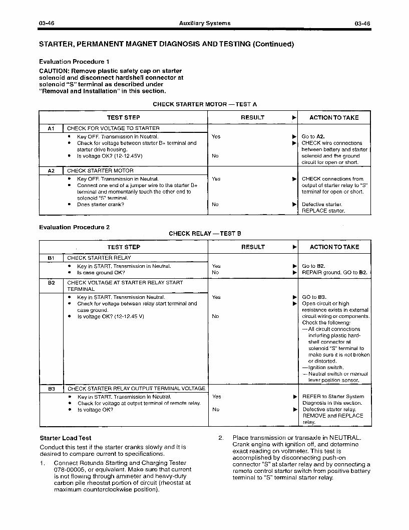
03-46 Auxiliary Systems 03-46
STARTER, PERMANENT MAGNET DIAGNOSIS AND TESTING (Continued)
Evaluation Procedure 1
CAUTION: Remove plastic safety cap on starter solenoid and disconnect hardshell connector at solenoid “S” terminal as described under “Removal and Installation” in this section.
CHECK STARTER MOTOR -TEST A
TEST STEP RESULT b
Al 1 CHECK FOR VOLTAGE TO STARTER
l Key OFF. Transmission in Neutral. l Check for voltage between starter B+ terminal and
starter drive housing. l Is voltage OK? (12-12.45V)
Yes
No
A2 1 CHECK STARTER MOTOR I
l Key OFF. Transmission in Neutral. l Connect one end of a jumper wire to the starter B+
terminal and momentarily touch the other end to solenoid “S” terminal.
Yes b
l Does starter crank? No b
Evaluation Procedure 2 CHECK RELAY -TEST B
TEST STEP
Bl 1 CHECK STARTER RELAY
l Key in START. Transmission in Neutral. l Is case ground OK?
B2 I
CHECK VOLTAGE AT STARTER RELAY START TERMINAL
l Key in START. Transmission Neutral. l Check for voltage between relay start terminal and
case ground. l Is voltage OK? (12-l 2.45 V)
B3 1 CHECK STARTER RELAY OUTPUT TERMINAL VOLTAGE 1
l Key in START. Transmission in Neutral. l Check for voltage at output terminal of remote relay. l Is voltage OK?
RESULT b
Yes No
b b
Yes
No
Yes
No
ACTION TO TAKE
Go to A2. CHECK wire connections between battery and starter solenoid and the ground circuit for open or short.
CHECK connections from output of starter relay to “S” terminal for open or short.
Defective starter. REPLACE starter.
ACTION TO TAKE
Go to B2. REPAIR ground. GO to B2.
GO to B3. Open circuit or high resistance exists in external circuit wiring or components. Check the following: -All circuit connections
including plastic hard- shell connector at solenoid “S” terminal to make sure it is not broken or distorted.
-Ignition switch. -Neutral switch or manual
lever position sensor.
REFER to Starter System Diagnosis in this section. Defective starter relay. REMOVE and REPLACE relay.
Starter Load Test 2. Place transmission or transaxle in NEUTRAL.
Conduct this test if the starter cranks slowly and it is desired to compare current to specifications.
1. Connect Rotunda Starting and Charging Tester 078-00005, or equivalent. Make sure that current is not flowing through ammeter and heavy-duty carbon pile rheostat portion of circuit (rheostat at maximum counterclockwise position).
Crank engine with ignition off, and determine exact reading on voltmeter. This test is accomplished by disconnecting push-on connector “S” atstarter relay and by connecting a remote control starter switch from positive battery terminal to “S” terminal starter relay.
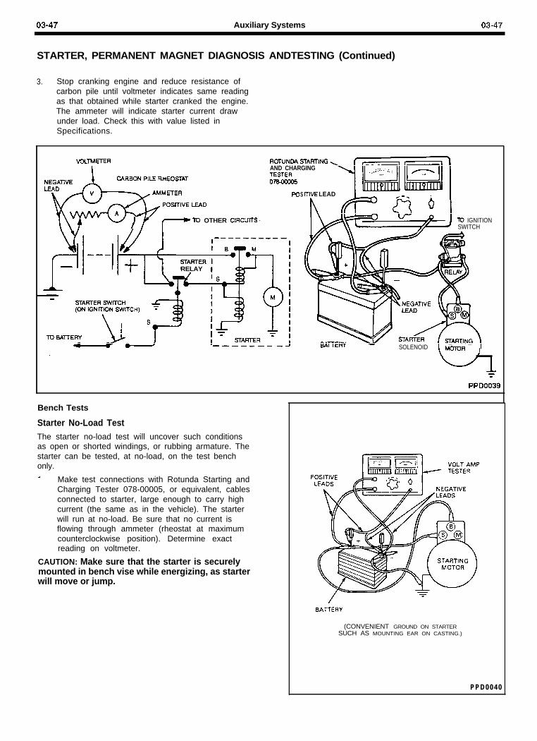
03-47 Auxiliary Systems 03-47
STARTER, PERMANENT MAGNET DIAGNOSIS ANDTESTING (Continued)
3. Stop cranking engine and reduce resistance ofcarbon pile until voltmeter indicates same readingas that obtained while starter cranked the engine.The ammeter will indicate starter current drawunder load. Check this with value listed inSpecifications.
AND CHARGINGTESTERnm-
Sd-WE LEAD
I\v - - u / y f-0 TD OTHER ClRCUfTS \
‘I-rI I RELAY 1
To IGNITIONSWITCH
ItHY -
\
- __ -_ _ - . . __SOLENOID MmR I
Bench Tests
Starter No-Load TestThe starter no-load test will uncover such conditionsas open or shorted windings, or rubbing armature. Thestarter can be tested, at no-load, on the test benchonly.A Make test connections with Rotunda Starting and
Charging Tester 078-00005, or equivalent, cablesconnected to starter, large enough to carry highcurrent (the same as in the vehicle). The starterwill run at no-load. Be sure that no current isflowing through ammeter (rheostat at maximumcounterclockwise position). Determine exactreading on voltmeter.
CAUTION: Make sure that the starter is securelymounted in bench vise while energizing, as starterwill move or jump.
BATTERY
(CONVENIENT GROUND ON STARTERSUCH AS MOUNTING EAR ON CASTING.)
P P D 0 0 4 0
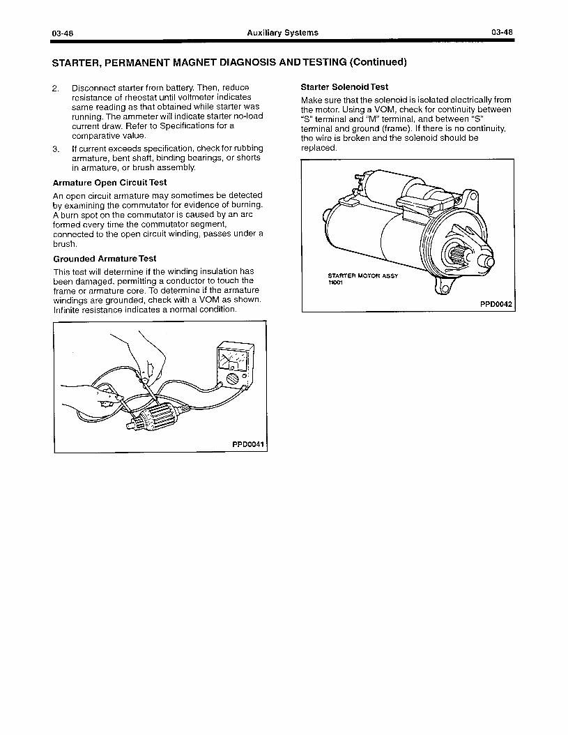
03-48 Auxiliary Systems 03-48
STARTER, PERMANENT MAGNET DIAGNOSIS ANDTESTING (Continued)
2. Disconnect starter from battery. Then, reduce resistance of rheostat until voltmeter indicates same reading as that obtained while starter was running. The ammeter will indicate starter no-load current draw. Refer to Specifications for a comparative value.
3. If current exceeds specification, check for rubbing armature, bent shaft, binding bearings, or shorts in armature, or brush assembly.
Armature Open Circuit Test
An open circuit armature may sometimes be detected by examining the commutator for evidence of burning. A burn spot on the commutator is caused by an arc formed every time the commutator segment, connected to the open circuit winding, passes under a brush.
Grounded Armature Test
This test will determine if the winding insulation has been damaged, permitting a conductor to touch the frame or armature core. To determine if the armature windings are grounded, check with a VOM as shown. Infinite resistance indicates a normal condition.
Starter Solenoid Test
Make sure that the solenoid is isolated electrically from the motor. Using a VOM, check for continuity between “S” terminal and “M” terminal, and between “S” terminal and ground (frame). If there is no continuity, the wire is broken and the solenoid should be replaced.
PPD0042
PPD0041
03-49 Auxiliary Systems
STARTER, PERMANENT MAGNET REMOVAL AND INSTALLATION
Starter Motor Installation
Removal
WARNING: WHEN SERVICING STARTER OR PERFORMING ANY MAINTENANCE INTHE AREA OFTHE STARTER, NOTETHATTHE HEAVY GAUGE INPUT LEAD CONNECTED TO THE STARTER SOLENOID IS HOT AT ALLTIMES. MAKE SURETHE PROTECTIVE CAP IS INSTALLED OVER THETERMINAL AND IS REPLACED AFTER SERVICE.
1. Disconnect the negative battery ground cable.
2. Disconnect starter cable and push-on connector from starter solenoid.
CAUTION: When disconnecting hardshell connector at “S” terminal, grasp the plastic shell and pull off. Do not pull on wire. Be careful to pull straight off to prevent damage to the connector and “S” terminal. If any part of the connection is damaged, replace the damaged components.
1. Position starter motor to engine and install upper and lower bolt finger-tight.
2. Tighten the upper bolt to 21-27 Nom (15-20 ft-lb). Access to upper bolt is with a 3/8 inch drive ratchet, swivel socket and a 22 inch long extension. Access is in front of, and along side, the right-hand front engine mount.
3. Tighten the lower bolt to 21-27 Nom (15-20 ft-lb).
4. Connect starter solenoid connector. Be careful to push straight on and make sure connector locks in position with a notable click or detent.
5. Install starter cable nut to starter terminal. Tighten to 9-l 3 Nom (80-I 20 in-lb).
6. Replace red solenoid safety cap.
7. Connect negative battery ground cable.
Wiring
3. Remove upper bolt with a 3/8 inch drive ratchet, swivel socket and a 22 inch long extension. Access is in front of, and along side, the right- hand front engine mount.
4. Remove lower bolt.
It is recommended that wiring service kit F2PZ-11 K162-A be used, which includes a 70 inch long #I2 gauge wire, a terminal nut, a terminal cover, four tie wraps and insulation instructions.
CAUTION: A jumper wire must not be installed between the large round electrical terminal and the solenoid blade terminal at the starter, to avoid use of the #I2 wire. If done, voltage is generated to the solenoid by the spinning starter after release of the start key or button, causing the starter to remain engaged, resulting in failure.
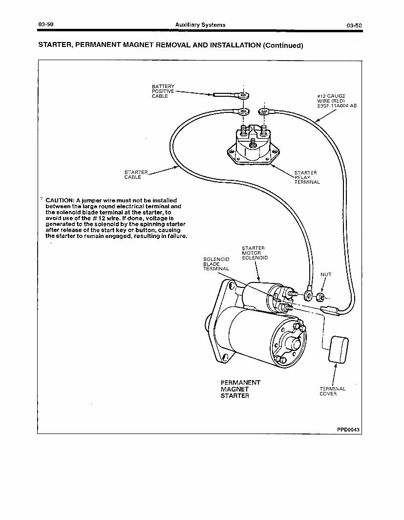
03-50 Auxiliary Systems
STARTER, PERMANENT MAGNET REMOVAL AND INSTALLATION (Continued)
03-50
BAl-i-ERY 8
#I2 GAUGE WIRE (RED)
STARTER CABLE
7 CAUTION: A jumper wire must not be installed between the large round electrical terminal and the solenoid blade terminal at the starter, to avoid use of the # 12 wire. If done, voltage is generated to the solenoid by the spinning starter after release of the start key or button, causing the starter to remain engaged, resulting in failure.
ESSF-1 IA004
TERMINAL
SOLENOID BLADE TERMINAL
STARTER MOTOR SOLENOID
-AB
PERMANENT I MAGNET TERMINAL
STARTER COVER
PPD0043
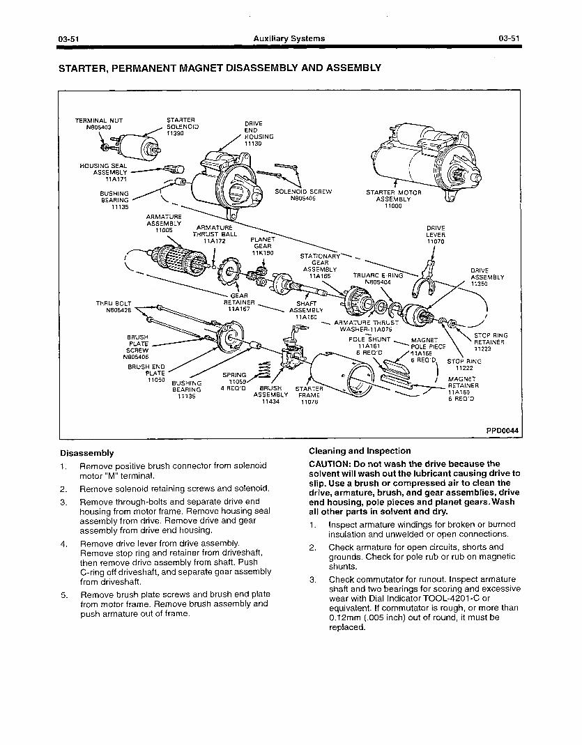
03-51 Auxiliary Systems 03-51
STARTER, PERMANENT MAGNET DISASSEMBLY AND ASSEMBLY
TERMINAL NUT STARTER N805403 / SOLENOID
11390
DRIVE END
/ HOUSING 11130
HOUSING SEAL -- WtJcJk ASSEMBLY -v
llA771
STARTEff’ MOTOR ASSEMBLY
BUSHING /! BEARING y \
ARMA-T ASSEM
77DC DRIVE LEVER
GEAR 17K190 STATfONARY. \
GEAR ASSEMBLY _ DRIVE
ASSEMBLY TRUARC
RETAINER . 17A767
THRU BOLT SHAm \ ASSEMBLY
17A160 N805428 \
STOP RING POLE<HUNT - - - - ----- MAGNET \ b _A. a -.c-c ’ RETAINER
BRUS PLATE
SCREW N805406
IwLt rltLt
\ 71223
17A168 6 REQ’D
I
STOP RING 11222 BRUSH END
Pl ATE 7 7050 i MAGNET
BUSHING BEARING
11135 4 REQ’D BRUSH STiRTEd
ASSEMBLY FRAME 71434 11076
PPDOO 44
Disassembly
1. Remove positive brush connector from solenoid motor “M” terminal.
2. Remove solenoid retaining screws and solenoid.
3. Remove through-bolts and separate drive end housing from motor frame. Remove housing seal assembly from drive. Remove drive and gear assembly from drive end housing.
4. Remove drive lever from drive assembly. Remove stop ring and retainer from driveshaft, then remove drive assembly from shaft. Push C-ring off driveshaft, and separate gear assembly from driveshaft.
Cleaning and Inspection
CAUTION: Do not wash the drive because the solvent will wash out the lubricant causing drive to slip. Use a brush or compressed air to clean the drive, armature, brush, and gear assemblies, drive end housing, pole pieces and planet gears. Wash all other parts in solvent and dry.
1. Inspect armature windings for broken or burned insulation and unwelded or open connections.
2. Check armature for open circuits, shorts and grounds. Check for pole rub or rub on magnetic shunts.
3. Check commutator for runout. Inspect armature shaft and two bearings for scoring and excessive wear with Dial Indicator TOOL-4201-C or equivalent. If commutator is rough, or more than 0.12mm (.005 inch) out of round, it must be replaced.
5. Remove brush plate screws and brush end plate from motor frame. Remove brush assembly and push armature out of frame.
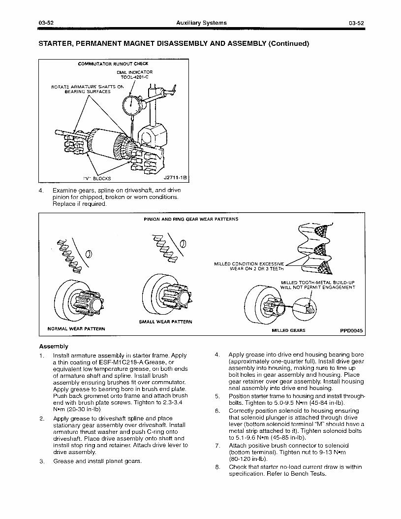
03-52 Auxiliary Systems 03-52
STARTER, PERMANENT MAGNET DISASSEMBLY AND ASSEMBLY (Continued)
COMMUTATOR RUNOUT CHECK
DIAL INDICATOR TOOL4201-C
1B
4. Examine gears, spline on driveshaft, and drive pinion for chipped, broken or worn conditions. Replace if required.
NORMAL WEAR PAl7ERN
PINION AND RING GEAR WEAR PAlTERNS
WEAR ON 2 OR 3 TEETH MILLED CONDITION EXCESSIVE
MlLtED TOOTH-METAL BUILD-UP
MILLED GEARS PPD0045
Assembly
1. Install armature assembly in starter frame. Apply a thin coating of ESF-MlC218-A Grease, or equivalent low temperature grease, on both ends of armature shaft and spline. Install brush assembly ensuring brushes fit over commutator. Apply grease to bearing bore in brush end plate. Push back grommet onto frame and attach brush end with brush plate screws. Tighten to 2.3-3.4 Nom (20-30 in-lb).
4. Apply grease into drive end housing bearing bore (approximately one-quarter full). Install drive gear assembly into housing, making sure to line up bolt holes in gear assembly and housing. Place gear retainer over gear assembly. Install housing seal assembly into drive end housing.
5. Position starter frame to housing and install through- bolts. Tighten to 5.0-9.5 Nom (45-84 in-lb).
6. Correctly position solenoid to housing ensuring that solenoid plunger is attached through drive lever (bottom solenoid terminal “M” should have a metal strip attached to it). Tighten solenoid bolts to 5.1-9.6 Nom (45-85 in-lb).
Apply grease to driveshaft spline and place stationary gear assembly over driveshaft. Install armature thrust washer and push C-ring onto driveshaft. Place drive assembly onto shaft and install stop ring and retainer. Attach drive lever to drive assembly.
Grease and install planet gears.
7. Attach positive brush connector to solenoid (bottom terminal). Tighten nut to 9-l 3 Nom (80-I 20 in-lb).
8. Check that starter no-load current draw is within specification. Refer to Bench Tests.
03-53 Auxiliary Systems 03-53
STARTER, PERMANENT MAGNET DISASSEMBLY AND ASSEMBLY (Continued)
Starter Drive Replacement Armature Replacement 1.
2.
3.
4.
5.
6.
7.
8 .
Remove positive brush connector from solenoid motor “M” terminal. Remove solenoid retaining screws and remove solenoid.
Remove through-bolts and separate motor assembly drive end housing. Remove housing seal from drive end housing. Remove drive gear assembly from housing and detach drive lever.
Remove stop ring and retainer from driveshaft and then remove drive assembly.
Apply a thin coating of ESF-Ml C218-A Grease, or equivalent low temperature grease, on driveshaft spline. Install new drive gear assembly on driveshaft. Install new stop ring and retainer. Attach drive lever.
Partially fill drive end housing bearing bore with grease (approximately one-quarter full). Install drive gear assembly in housing, making sure to line up bolt holes in gear assembly and housing.
I nstal housi
I leve w
r support and housing seal in drive end
Position starter frame to housing and install through-bolts. Tighten to 5.0-9.5 Nom (45-84 in-lb).
Install solenoid. Refer to Assembly.
5.
Remove positive brush connector from solenoid motor “M” terminal.
Remove through-bolts and separate motor from gear assembly and drive end housing.
Remove brush end plate screws, brush end plate and brush assembly from starter frame. Remove armature from frame.
Install new armature in frame. Apply a thin coating of ESF-Ml C218-A Grease, or equivalent low temperature grease, on both ends of armature shaft and pinion.
Install brush assembly. Using tool, make sure that brushes fit over commutator. Push black grommet onto frame. Apply grease to bearing bore in brush end plate and attach to starter frame.
Position starter frame to gear assembly and drive end housing and install through-bolts. Tighten to 5.0-9.5 Nom (45-84 in-lb).
Attach positive brush connector to solenoid (bottom terminal). Tighten nut to 9-13 Nom (80-I 20 in-lb).
Check that starter no-load current draw is within specification. Refer to Bench Testing.
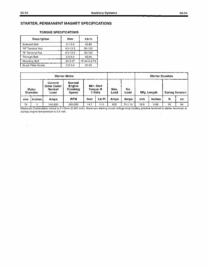
03-54 Auxiliary Systems 03-54
STARTER, PERMANENT MAGNET SPECIFICATIONS
TORQUE SPECIFICATIONS
Description I
Nom I
Lb-In I
1 Solenoid Bolt 1 5.1-9.6 1 45-85 1
1 “M” Terminal Nut I 9.0-13.5 I 80-120 1
1 “B” Terminal Nut 1 9.0-13.5 1 80-120 I
I Throuah-Bolt 1 5.0-9.5 1 45-84 1
1 Mounting Bolt I 20.3-27 1 15-20 (Lb-Ft) 1
1 Brush Plate Screw I 2.3-3.4 1 20-30 1
Starter Motor Starter Brushes
Current Normal Draw Under Engine Min. Stall
Motor Normal Cranking Torque @I Max. No Diameter Load Speed 5 Volts Load Load Mfg. Length Spring Tension
mm Inches Amps RPM Nom Lb-Ft Amps Amps mm Inches N 02.
78 3 140-200 200-250 14.7 11.0 800 70+10 16.8 0.66 18 64
Maximum Commutator runout is 0.12mm (0.005 inch). Maximum starting circuit voltage drop (battery positive terminal to starter terminal) at normal engine temperature is 0.5 volt.
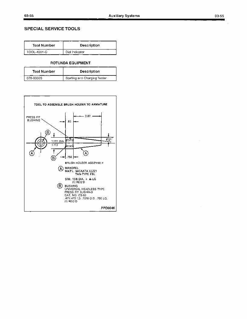
03-55 Auxiliary Systems 03-55
SPECIAL SERVICE TOOLS
I Tool Number I Description I
1 TOOL-4201-C I Dial Indicator I
ROTUNDA EQUIPMENT
I Tool Number Description
I 078-00005 I Starting and Charging Tester I
TOOL TO ASSEMBLE BRUSH HOLDER TO ARMATURE
PRESS FIT < 3.80 .
e .83 -
BRUSH HOLOER ASSEMBLY
0 A MANDREL MAT’L: MICAATA LL22 1
TAN-TYPE FBL
0 6 STK: l3/8 DIA. + A-LG
(1) REQ’O BUSHING UNIVERSAL HEAOLESS TYPE PRESS FIT BUSHING CAT. NO. GS-93 .471/.472 I.D. .7518 0.0. .750 LG. (1) REQ’O
PPD0046
03-56 Auxiliary Systems 03-56
GOVERNORS, MECHANICAL DESCRIPTION AND OPERATION
The mechanical flyweight type governors can be used on these engines. They are belt-driven from the front of the engine.
A direct mechanical linkage from the governor throttle control lever to the carburetor throttle lever limits carburetor action to the governor setting. As the engine speed increases, the rotation of the governor shaft increases. Centrifugal force causes the weights to move outward as the rotation of the governor shaft increases. However, a spring retards or limits the movement of the weights until centrifugal force overcomes the spring tension. At this time the weights are forced outward, closing the throttle plates through the linkage to the throttle shaft.
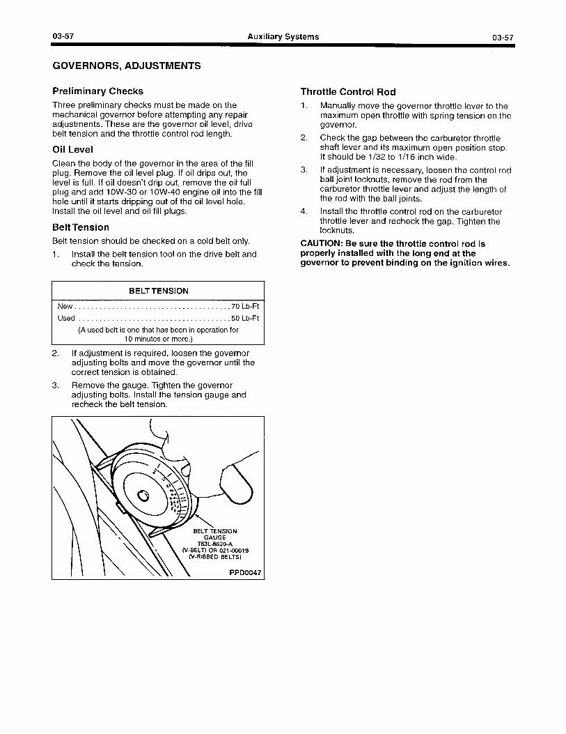
03-57 Auxiliary Systems 03-57
GOVERNORS, ADJUSTMENTS
Preliminary Checks Throttle Control Rod Three preliminary checks must be made on the mechanical governor before attempting any repair adjustments. These are the governor oil level, drive belt tension and the throttle control rod length.
Oil Level Clean the body of the governor in the area of the fill plug. Remove the oil level plug. If oil drips out, the level is full. If oil doesn’t drip out, remove the oil full plug and add 1 OW-30 or 1 OW-40 engine oil into the fill hole until it starts dripping out of the oil level hole. Install the oil level and oil fill plugs.
1. Manually move the governor throttle lever to the maximum open throttle with spring tension on the governor.
2. Check the gap between the carburetor throttle shaft lever and its maximum open position stop. It should be l/32 to l/l 6 inch wide.
Belt Tension
3. If adjustment is necessary, loosen the control rod ball joint locknuts, remove the rod from the carburetor throttle lever and adjust the length of the rod with the ball joints.
4. Install the throttle control rod on the carburetor throttle lever and recheck the gap. Tighten the locknuts.
Belt tension should be checked on a cold belt only.
1. Install the belt tension tool on the drive belt and check the tension.
CAUTION: Be sure the throttle control rod is properly installed with the long end at the governor to prevent binding on the ignition wires.
BELT TENSION
New......................................70Lb-Ft
Used . . . . . . . . . . . . . . . . . . . . . . . . . . . . . . . . . . ...50 Lb-Ft
(A used belt is one that has been in operation for IO minutes or more.)
2. If adjustment is required, loosen the governor adjusting bolts and move the governor until the correct tension is obtained.
3. Remove the gauge. Tighten the governor adjusting bolts. Install the tension gauge and recheck the belt tension.
W8ELT) OR 02140019 (V-RIBBED BELTS)
PPD0047
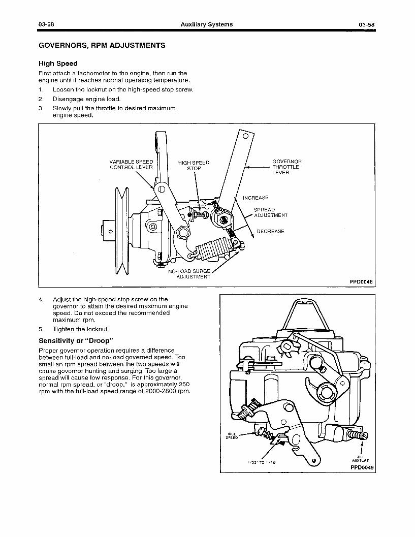
03-58 Auxiliary Systems 03-58
GOVERNORS, RPM ADJUSTMENTS
High Speed First attach a tachometer to the engine, then run the engine until it reaches normal operating temperature.
1. Loosen the locknut on the high-speed stop screw.
2. Disengage engine load.
3. Slowly pull the throttle to desired maximum engine speed.
VARIABLE CONTROL
HIGH SPEED
LEVER
GOVERNOR THRO-T-I-LE
ADJUSTMENT
NO-LOAD SURGE ADJUSTMENT
PPD0048
4. Adjust the high-speed stop screw on the governor to attain the desired maximum engine speed. Do not exceed the recommended maximum rpm.
5. Tighten the locknut.
Sensitivity or “Droop” Proper governor operation requires a difference between full-load and no-load governed speed. Too small an rpm spread between the two speeds will cause governor hunting and surging. Too large a spread will cause low response. For this governor, normal rpm spread, or “droop,” is approximately 250 rpm with the full-load speed range of 2000-2800 rpm.
/ IDLE
l/32” T; l/16” MIXTURE
PPD0049
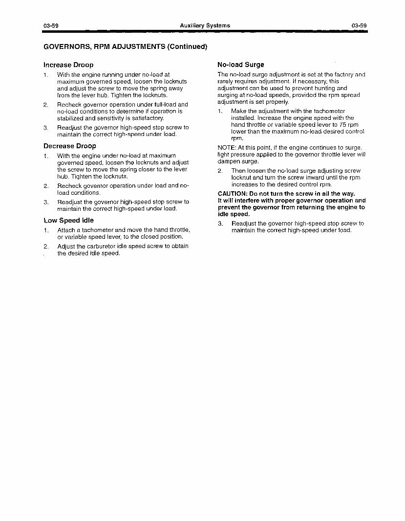
03-59 Auxiliary Systems 03-59
GOVERNORS, RPM ADJUSTMENTS (Continued)
Increase Droop No-load Surge
1. With the engine running under no-load at The no-load surge adjustment is set at the factory and maximum governed speed, loosen the locknuts rarely requires adjustment. If necessary, this and adjust the screw to move the spring from the lever hub. Ti gh ten the locknuts.
away adjustment can be used to prevent hunting a nd surging at no-load speeds, provided the rpm spread -
2. Recheck governor operation under full-load and adjustment is set properly.
no-load conditions to determine if operation is 1. Make the adjustment with the tachometer stabilized and sensitivity is satisfactory.
3. Readjust the governor high-speed stop screw to maintain the correct high-speed under load.
Decrease Droop 1. With the engine under no-load at maximum
governed speed, loosen the locknuts and adjust the screw to move the spring closer to the lever hub. Tighten the locknuts.
2. Recheck governor operation under load and no- load conditions.
3. Readjust the governor high-speed stop screw to maintain the correct high-speed under load.
installed. Increase the engine speed with the hand throttle or variable speed lever to 75 rpm lower than the maximum no-load desired control rpm.
NOTE: At this point, if the engine continues to surge, light pressure applied to the governor throttle lever will dampen surge.
2. Then loosen the no-load surge adjusting screw locknut and turn the screw inward until the rpm increases to the desired control rpm.
CAUTION: Do not turn the screw in all the way. It will interfere with proper governor operation and prevent the governor from returning the engine to idle speed.
Low Speed Idle 1. Attach a tachometer and move the hand throttle,
or variable speed lever, to the closed position.
2. Adjust the carburetor idle speed screw to obtain the desired idle speed.
3. Readjust the governor high-speed stop screw to maintain the correct high-speed under load.
03-60 Auxiliary Systems 03-60
GOVERNORS, REMOVAL AND INSTALLATION
Removal Installation 1.
2.
3.
4.
5.
Disconnect hand throttle connection at governor variable speed lever.
1.
Disconnect governor to carburetor throttle control rod at governor.
2.
Loosen governor mounting nuts and bolts and move governor toward engine to loosen drive belt.
3.
4. Remove drive belt from governor pulley.
Remove governor to bracket attaching bolts and remove governor. 5.
Position the governor to the mounting bracket and install the attaching bolts snugly.
Position drive belt to governor pulley and move the governor away from the engine to tighten the belt. Tighten the attaching bolts.
Adjust the belt tension.
Connect the governor to carburetor throttle control rod. Adjust the rod as described previously.
Connect hand throttle cable to governor variable speed lever. Adjust cable as necessary to permit operation from idle to maximum speed.
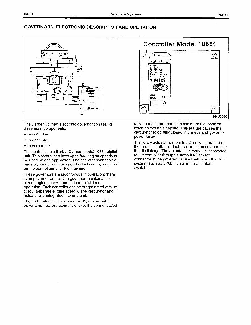
03-61 Auxiliary Systems 03-61
GOVERNORS, ELECTRONIC DESCRIPTION AND OPERATION
Controller Model 10851
PPD0050
The Barber Colman electronic governor consists of three main components:
l a controller
l an actuator
l a carburetor
The controller is a Barber Colman model 10851 digital unit. This controller allows up to four engine speeds to be used on one application. The operator changes the engine speeds via a run speed select switch, mounted on the control panel of the machine.
These governors are isochronous in operation; there is no governor droop. The governor maintains the same engine speed from no-load to full-load operation. Each controller can be programmed with up to four separate engine speeds. The carburetor and actuator are integrated into one unit.
The carburetor is a Zenith model 33, offered with either a manual or automatic choke. It is spring loaded
to keep the carburetor at its minimum fuel position when no power is applied. This feature causes the carburetor to go fully closed in the event of governor power failure.
The rotary actuator is mounted directly to the end of the throttle shaft. This feature eliminates any need for throttle linkage. The actuator is electrically connected to the controller through a two-wire Packard connector. If the governor is used with any other fuel system, such as LPG, then a linear actuator is available.
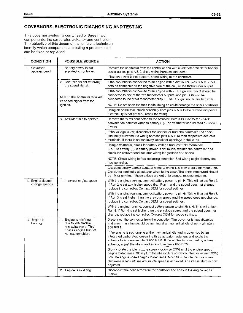
03-62 Auxiliary Systems 03-62
GOVERNORS, ELECTRONIC DIAGNOSING AND TESTING
This governor system is comprised of three major components: the carburetor, actuator and controller. The objective of this document is to help a technician identify which component is creating a problem so it can be fixed or replaced.
CONDITION
I. Governor appears dead.
POSSIBLE SOURCE
1. Battery power is not supplied to controller.
2. Controller is not receiving the speed signal.
ACTION
Remove the connector from the controller and with a voltmeter check for battery power across pins A & B of the wiring harness connector.
If battery power is not present, check wiring to the controller.
If the controller is connected to an engine with a distributor, pins C & D should both be connected to the negative side of the coil, or the tachometer output.
If the controller is connected to an engine with a DIS ignition, pin C should be
NOTE: This controller receives connected to one of the two tachometer outputs, and pin D should be
its speed signal from the connected to the other tachometer output. The DIS ignition utilizes two coils.
ignition. NOTE: Do not short the tach leads; doing so could damage the spark controller.
Using an ohmmeter, check continuity from pins C & D to the termination points. If continuity is not present, repair the wiring.
3. Actuator fails to operate. Remove the wires connected to the actuator. With a DC voltmeter, check between the actuator wires to battery (-). The voltmeter should read 12 volts t 2 volts.
If the voltage is low, disconnect the connector from the controller and check continuity between the wiring harness pins E & F, to their respective actuator
. terminals. If there is no continuity, check for openings in the wires.
Using a voltmeter, check for battery voltage from controller terminals E & F to battery (-). If battery power is not found, replace the controller and check the actuator and actuator wiring for grounds and shorts.
NOTE: Check wiring before replacing controller. Bad wiring might destroy the new controller.
I I. Engine doesn’t change speeds.
Ill. Engine is hunting.
1. Incorrect engine speed
1. Engine is misfiring due to idle mixture mis-adjustment. This causes engine hunt at no-load condition.
2. Engine is misfiring.
Check continuity across actuator wires. 2 ohms + 5 ohm should be measured. Check the continuity of actuator wires to the case. The ohms measured should be 1 M or greater. If these values are out of tolerance, replace actuator.
With the engine running, connect battery power to pin H. This will select Run 2. If Run 2 is set at a higher speed than Run 1 and the speed does not change, replace the controller. Contact OEM for speed settings.
With the engine running, connect battery power to pin G. This will select Run 3. If Run 3 is set higher than the previous speed and the speed does not change, replace the controller. Contact OEM for speed settings.
With the engine running, connect battery power to pins G & H. This will select Run 4. If Run 4 is set higher than the previous speed and the speed does not change, replace the controller. Contact OEM for speed settings.
Disconnect the connector from the controller. The governor is now disabled and a warm engine should be running at a mechanical idle of approximately 600 RPM.
If the engine is not running at the mechanical idle and is governed by an integrated carburetor, loosen the three actuator fasteners and rotate the actuator to achieve an idle of 600 RPM. If the engine is governed by a linear actuator, adjust the idle speed screw to achieve 600 RPM.
Slowly rotate the idle mixture screw clockwise (CW) until the engine speed begins to decrease. Slowly turn the idle mixture screw counterclockwise (CCW) until the engine speed begins to decrease. Now, turn the idle mixture screw clockwise (CW) until maximum idle speed is achieved. The idle mixture is now adjusted.
Disconnect the connector from the controller and consult the engine repair manual.
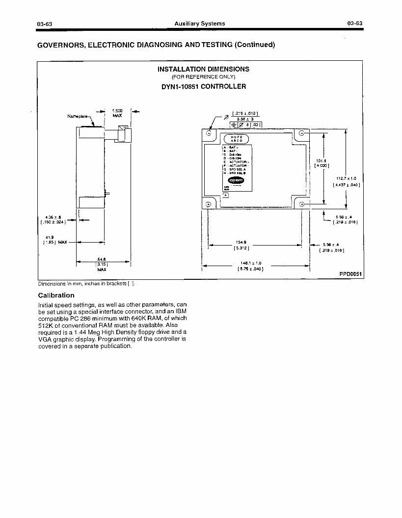
03-63 Auxiliary Systems 03-63
GOVERNORS, ELECTRONIC DIAGNOSING AND TESTING (Continued)
INSTALLATION DIMENSIONS (FOR REFERENCE ONLY)
DYNl-10851 CONTROLLER
112.7 ?I
(4.437L
t 5.56 *.I [.219 ?.018]
134.9 - (5.312I
5.%*.4
(.219~.Olej
148.1 il.0
- [5.75r.o40] PPD0051
Dimensions in mm, inches in brackets [ 1.
Calibration Initial speed settings, as well as other parameters, can be set using a special interface connector, and an IBM compatible PC 286 minimum with 640K RAM, of which 512K of conventional RAM must be available. Also required is a 1.44 Meg High Density floppy drive and a VGA graphic display. Programming of the controller is covered in a separate publication.
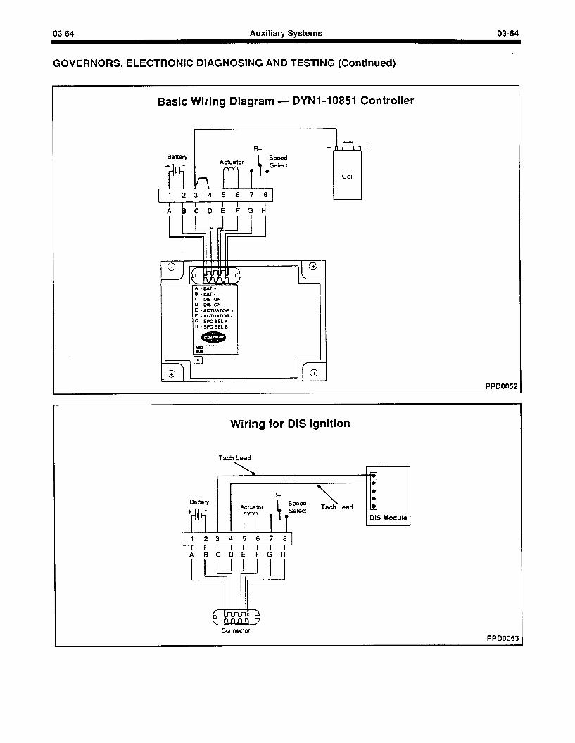
03-64 Auxiliary Systems 03-64
GOVERNORS, ELECTRONIC DIAGNOSING AND TESTING (Continued)
Basic Wiring Diagram - DYNl-10851 Controller
1123456781 1 1 I I I 1 1 1 1
ABCDEFGH
II I G -SPOSELA H -SPOSELB I I
!nr
Coil LJ +
PPD0052
Wiring for DIS Ignition
Tach Lead
1 23 4 5 6 7 81 I I I I I I I I ABCDEFGH
PPD0053
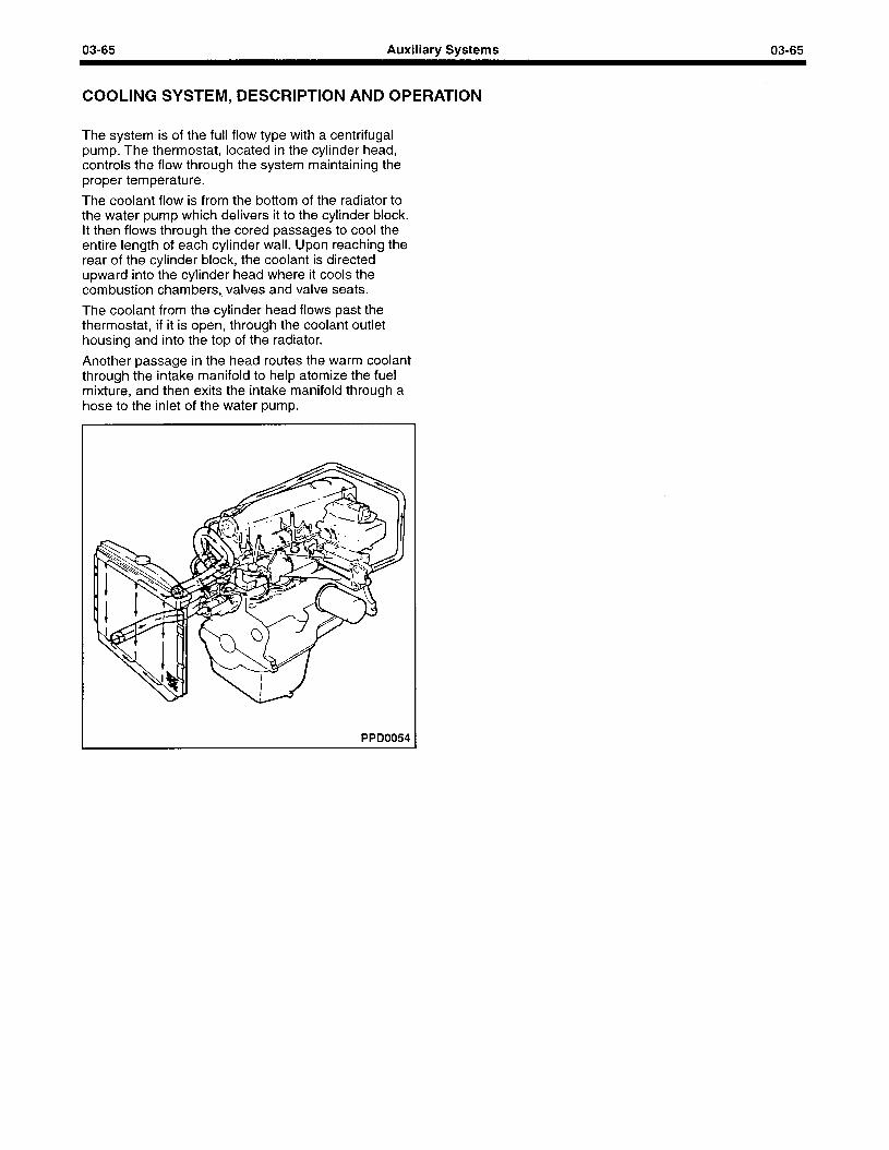
03-65 Auxiliary Systems 03-65
COOLING SYSTEM, DESCRIPTION AND OPERATION
The system is of the full flow type with a centrifugal pump. The thermostat, located in the cylinder head, controls the flow through the system maintaining the proper temperature.
The coolant flow is from the bottom of the radiator to the water pump which delivers it to the cylinder block. It then flows through the cored passages to cool the entire length of each cylinder wall. Upon reaching the rear of the cylinder block, the coolant is directed upward into the cylinder head where it cools the combustion chambers, valves and valve seats.
The coolant from the cylinder head flows past the thermostat, if it is open, through the coolant outlet housing and into the top of the radiator.
Another passage in the head routes the warm coolant through the intake manifold to help atomize the fuel mixture, and then exits the intake manifold through a hose to the inlet of the water pump.
PPD0054
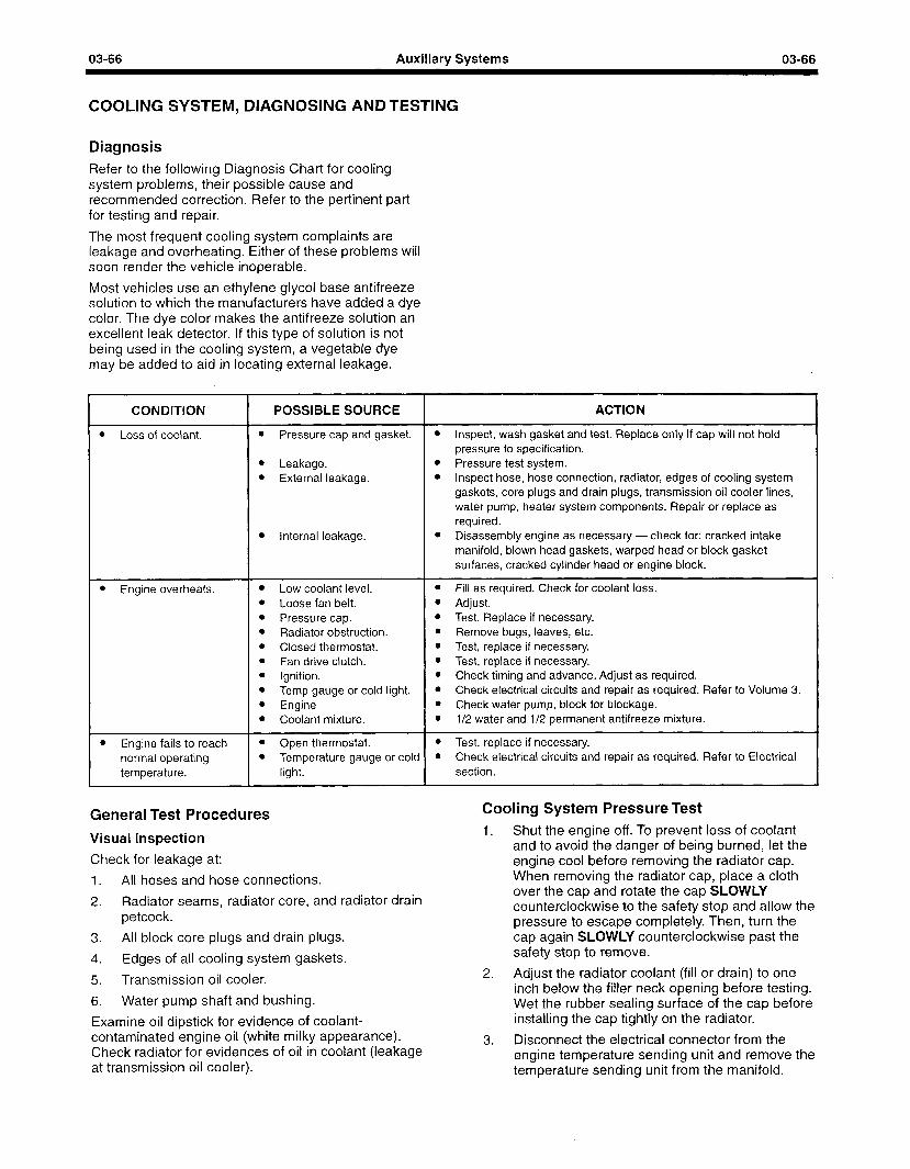
03-66 Auxiliary Systems 03-66
COOLING SYSTEM, DIAGNOSING AND TESTING
Diagnosis Refer to the following Diagnosis Chart for cooling system problems, their possible cause and recommended correction. Refer to the pertinent part for testing and repair.
The most frequent cooling system complaints are leakage and overheating. Either of these problems will soon render the vehicle inoperable.
Most vehicles use an ethylene glycol base antifreeze solution to which the manufacturers have added a dye color. The dye color makes the antifreeze solution an excellent leak detector. If this type of solution is not being used in the cooling system, a vegetable dye may be added to aid in locating external leakage.
CONDITION
l Loss of coolant.
POSSIBLE SOURCE ACTION
l Pressure cap and gasket. l Inspect, wash gasket and test. Replace only if cap will not hold pressure to specification.
l Leakage. l Pressure test system. l External leakage. l Inspect hose, hose connection, radiator, edges of cooling system
gaskets, core plugs and drain plugs, transmission oil cooler lines, water pump, heater system components. Repair or replace as required.
l Internal leakage. l Disassembly engine as necessary - check for: cracked intake manifold, blown head gaskets, warped head or block gasket surfaces, cracked cylinder head or engine block.
l Engine overheats.
l Engine fails to reach normal operating temperature.
l Low coolant level. * Fill as required. Check for coolant loss. l Loose fan belt. l Adjust. l Pressure cap. l Test. Replace if necessary. l Radiator obstruction. l Remove bugs, leaves, etc. l Closed thermostat. l Test, replace if necessary. l Fan drive clutch. l Test, replace if necessary. l Ignition. 0 Check timing and advance. Adjust as required. l Temp gauge or cold light. l Check electrical circuits and repair as required. Refer to Volume 3. l Engine 0 Check water pump, block for blockage. l Coolant mixture. l l/2 water and l/2 permanent antifreeze mixture.
l Open thermostat. l Test, replace if necessary. l Temperature gauge or cold l Check electrical circuits and repair as required. Refer to Electrical
light. section.
General Test Procedures
Visual Inspection
Check for leakage at:
1. All hoses and hose connections.
2. Radiator seams, radiator core, and radiator drain petcock.
3. All block core plugs and drain plugs.
4, Edges of all cooling system gaskets.
5. Transmission oil cooler.
6. Water pump shaft and bushing.
Examine oil dipstick for evidence of coolant- contaminated engine oil (white milky appearance). Check radiator for evidences of oil in coolant (leakage at transmission oil cooler).
Cooling System Pressure Test 1. Shut the engine off. To prevent loss of coolant
and to avoid the danger of being burned, let the engine cool before removing the radiator cap. When removing the radiator cap, place a cloth over the cap and rotate the cap SLOWLY counterclockwise to the safety stop and allow the pressure to escape completely. Then, turn the cap again SLOWLY counterclockwise past the safety stop to remove.
2. Adjust the radiator coolant (fill or drain) to one inch below the filler neck opening before testing. Wet the rubber sealing surface of the cap before installing the cap tightly on the radiator.
3. Disconnect the electrical connector from the engine temperature sending unit and remove the temperature sending unit from the manifold.
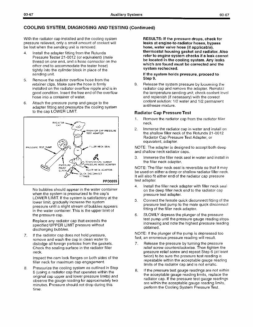
03-67 Auxiliary Systems 03-67
COOLING SYSTEM, DIAGNOSING AND TESTING (Continued)
With the radiator cap installed and the cooling system pressure relieved, only a small amount of coolant will be lost when the sending unit is removed.
4. Install the adapter fitting from the Rotunda Pressure Tester 21-0012 (or equivalent) (male thread on one end, and a hose connector on the other end to accommodate the tester hose) tightly into the cylinder block in place of the sending unit.
5. Remove the radiator overflow hose from the retainer clips. Make sure the hose is firmly installed on the radiator overflow nipple and is in good condition. Insert the free end of the overflow hose into a container of water.
6. Attach the pressure pump and gauge to the adapter fitting and pressurize the cooling system to the cap LOWER LIMIT.
RADIATOR CAP
RADIATOR CAP PRESSURE TEST ADAPTOR
FILLER NECK SEAL
OUICK DISCONNECT &- FITTINGS
PPD0055
No bubbles should appear in the water container when the system is pressurized to the cap’s LOWER LIMIT. If the system is satisfactory at the lower limit, gradually increase the system pressure until a slight stream of bubbles appears in the water container. This is the upper limit of the pressure cap.
Replace any radiator cap that exceeds the specified UPPER LIMIT pressure without discharging bubbles.
7. If the radiator cap does not hold pressure, remove and wash the cap in clean water to dislodge all foreign particles from the gaskets. Check the sealing surface in the radiator filler neck.
Inspect the cam lock flanges on both sides of the filler neck for maximum cap engagement.
8. Pressurize the cooling system as outlined in Step 6 (using a radiator cap that operates within the original cap upper and lower pressure limits) and observe the gauge reading for approximately two minutes. Pressure should not drop during this time.
RESULTS: If the pressure drops, check for leaks at engine-to-radiator hoses, bypass hose, water valve hose (if applicable), thermostat housing gasket and radiator. Also refer to engine system checks if a leak cannot be located in the cooling system. Any leaks which are found must be corrected and the system rechecked.
If the system holds pressure, proceed to Step 9.
9. Release the system pressure by loosening the radiator cap and remove the adapter. Reinstall the temperature sending unit, check coolant level and replenish (if necessary) with the correct coolant solution: l/2 water and l/2 permanent antifreeze mixture.
Radiator Cap Pressure Test 1. Remove the radiator cap from the radiator filler
neck.
2. Immerse the radiator cap in water and install on the shallow filler neck of the Rotunda 21-0012 Radiator Cap Pressure Test Adapter, or equivalent, adapter.
NOTE: The adapter is designed to accept both deep and shallow neck radiator caps.
3. Immerse the filler neck seal in water and install in the filler neck adapter.
NOTE: The filler neck seal is reversible so that it may be used on either a deep or shallow radiator filler neck. It will also fit either end of the radiator cap pressure test adapter.
4. Install the filler neck adapter with filler neck seal on the deep filler neck end to the radiator cap pressure test adapter.
5. Connect the female quick disconnect fitting of the pressure test pump to the male quick disconnect fitting of the filler neck adapter.
6. SLOWLY depress the plunger of the pressure test pump until the pressure gauge reading stops increasing and note the highest pressure reading obtained.
NOTE: If the plunger of the pump is depressed too fast, an erroneous pressure reading will result.
7. Release the pressure by turning the pressure relief screw counterclockwise. Then tighten the pressure relief screw and repeat Step 6 (at least twice) to be sure the pressure test reading is repeatable within the acceptable gauge reading limits of the radiator cap and is not erratic.
8. If the pressure test gauge readings are not within the acceptable gauge reading limits, replace the radiator cap. If the pressure test gauge readings are within the acceptable gauge reading limits, perform the Cooling System Pressure Test.
03-68 Auxiliary Systems 03-68
COOLING SYSTEM, DIAGNOSING AND TESTING (Continued)
Thermostat Test -Thermostat Removed Remove the thermostat and immerse it in boiling water. Replace the thermostat if it does not open at least 0.230” after one minute at 212°F.
If the problem being investigated is the inability of the cooling system to reach normal operating temperature, the thermostat should be checked for leakage. This may be done by holding the thermostat up to the lighted background. Leakage of light all around the thermostat valve (thermostat at room temperature) indicates that the thermostat is unacceptable and should be replaced. It is possible, on some thermostats, that a slight leakage of light at one or two locations on the perimeter of the valve may be detected. This should be considered normal.
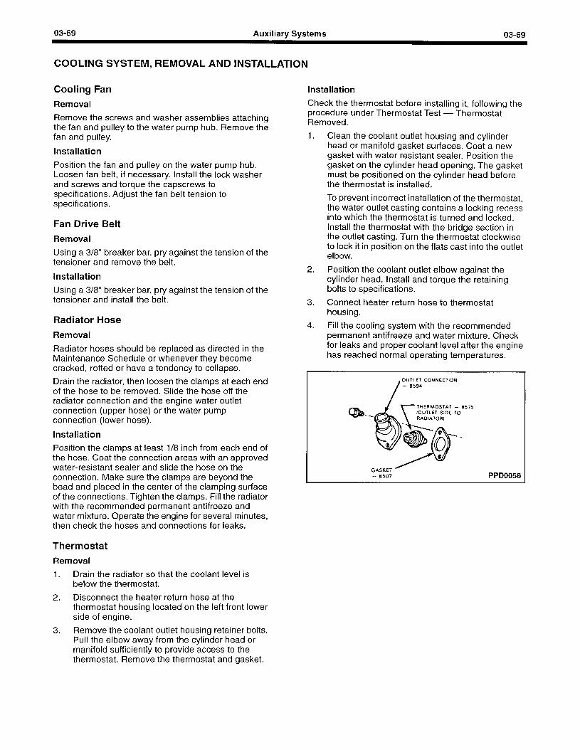
03-69 Auxiliary Systems 03-69
COOLING SYSTEM, REMOVAL AND INSTALLATION
Cooling Fan
Removal
Remove the screws and washer assemblies attaching the fan and pulley to the water pump hub. Remove the fan and pulley.
Installation
Position the fan and pulley on the water pump hub. Loosen fan belt, if necessary. Install the lock washer and screws and torque the capscrews to specifications. Adjust the fan belt tension to specifications.
Fan Drive Belt
Removal
Using a 3/8” breaker bar, pry against the tension of the tensioner and remove the belt.
Installation
Using a 3/8” breaker bar, pry against the tension of the tensioner and install the belt.
Radiator Hose
Removal
Radiator hoses should be replaced as directed in the Maintenance Schedule or whenever they become cracked, rotted or have a tendency to collapse.
Drain the radiator, then loosen the clamps at each end of the hose to be removed. Slide the hose off the radiator connection and the engine water outlet connection (upper hose) or the water pump connection (lower hose).
Installation
Position the clamps at least l/8 inch from each end of the hose. Coat the connection areas with an approved water-resistant sealer and slide the hose on the connection. Make sure the clamps are beyond the bead and placed in the center of the clamping surface of the connections. Tighten the clamps. Fill the radiator with the recommended permanent antifreeze and water mixture. Operate the engine for several minutes, then check the hoses and connections for leaks.
Thermostat
Removal
1. Drain the radiator so that the coolant level is below the thermostat.
2. Disconnect the heater return hose at the thermostat housing located on the left front lower side of engine.
3. Remove the coolant outlet housing retainer bolts. Pull the elbow away from the cylinder head or manifold sufficiently to provide access to the thermostat. Remove the thermostat and gasket.
Installation
Check the thermostat before installing it, following the procedure under Thermostat Test - Thermostat Removed.
1. Clean the coolant outlet housing and cylinder head or manifold gasket surfaces. Coat a new gasket with water resistant sealer. Position the gasket on the cylinder head opening. The gasket must be positioned on the cylinder head before the thermostat is installed.
To prevent incorrect installation of the thermostat, the water outlet casting contains a locking recess into which the thermostat is turned and locked. Install the thermostat with the bridge section in the outlet casting. Turn the thermostat clockwise to lock it in position on the flats cast into the outlet elbow.
2. Position the coolant outlet elbow against the cylinder head. Install and torque the retaining bolts to specifications.
3. Connect heater return hose to thermostat housing.
4. Fill the cooling system with the recommended permanent antifreeze and water mixture. Check for leaks and proper coolant level after the engine has reached normal operating temperatures.
, OUTLET CONNECTION
- 8575 TO
PPD0056
03-70 Auxiliary Systems 03-70
COOLING SYSTEM, CLEANING AND INSPECTION
Cleaning Cooling System To remove rust, sludge and other foreign material from the cooling system, use Rotunda Cooling System Cleanser. Removal of such material restores cooling efficiency and avoids overheating. Always remove the thermostat prior to pressure flushing. A pulsating or reversed direction of flushing water flow will loosen sediment more quickly than a steady flow in the normal direction of coolant flow. In severe cases where cleaning solvents will not properly clean the cooling system for efficient operation, it will be necessary to use the pressure flushing method. Various types of flushing equipment are available.
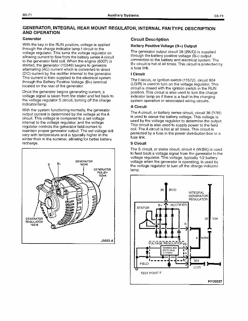
03-71 Auxiliary Systems 03-71
GENERATOR, INTEGRAL REAR MOUNT REGULATOR, INTERNAL FAN TYPE DESCRIPTION AND OPERATION
Generator
With the key in the RUN position, voltage is applied through the charge indicator lamp I circuit to the voltage regulator. This turns the voltage regulator on allowing current to flow from the battery sense A circuit to the generator field coil. When the engine (6007) is started, the generator (10346) begins to generate alternating (AC) current which is converted to direct (DC) current by the rectifier internal to the generator. This current is then supplied to the electrical system through the Battery Positive Voltage (B+) terminal located on the rear of the generator.
Once the generator begins generating current, a voltage signal is taken from the stator and fed back to the voltage regulator S circuit, turning off the charge indicator/lamp.
With the system functioning normally, the generator output current is determined by the voltage at the A circuit. This voltage is compared to a set voltage internal to the voltage regulator, and the voltage regulator controls the generator field current to maintain proper generator output. The set voltage will vary with temperature and is typically higher in the winter than in the summer, allowing for better battery recharge.
GENERATOR 10346
GENERATOR PULLEY
44
Circuit Description
Battery Positive Voltage (B+) Output
The generator output circuit 38 (BWO) is supplied through the battery positive voltage (B+) output connection to the battery and electrical system. The B+ circuit is hot at all times. This circuit is protected by a fuse link.
I Circuit
The I circuit, or ignition switch (11572), circuit 904 (LG/R) is used to turn on the voltage regulator. This circuit is closed with the ignition switch in the RUN position. This circuit is also used to turn the charge indicator lamp on if there is a fault in the charging system operation or associated wiring circuits.
A Circuit
The A circuit, or battery sense circuit, circuit 36 (Y/W) is used to sense the battery voltage. This voltage is used by the voltage regulator to determine the output. This circuit is also used to supply power to the field coil. The A circuit is hot at all times. This circuit is protected by a fuse in the power distribution box or a fuse link.
S Circuit
The S circuit, or stator circuit, circuit 4 (W/BK) is used to feed back a voltage signal from the generator to the voltage regulator. This voltage, typically l/2 battery voltage when the generator is operating, is used by the voltage regulator to turn off the charge indicator lamp.
J5683-A
38
I
BWO
T -I)-----li-LIII.
VOLTAGE REGULATOR 1s
1 FIELD
TEST POINT F
REGULATOR
1 904
He+ LG/R
PPD0057
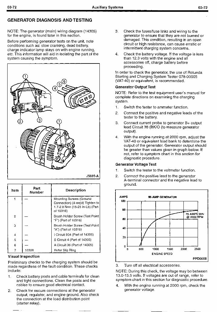
03-72 Auxiliary Systems 03-72
GENERATOR DIAGNOSIS ANDTESTING
NOTE: The generator (main) wiring diagram (14305) for the engine, is found later in this section.
Before performing generator tests on the unit, note conditions such as: slow cranking, dead battery, charge indicator lamp stays on with engine running, etc. This information will aid in isolating the part of the , system causing the symptom.
J5695-A
Item Part
Number Description
1 - Mounting Screws (Ground Connection) (4 req’d) Tighten to 1.7-2.8 Nom (15-25 In-Lb) (Part of 10316)
2 - Brush Holder Screw (Test Point “F”) (Part of 10316)
3 - Brush Holder Screw (Test Point “A”) (Part of 10316)
4 - I Circuit 904 (Part of 14305)
5 - S Circuit 4 (Part of 14305)
6 - A Circuit 36 (Part of 14305)
7 10328 Rotor Slip Ring
Visuall inspection
Preliminary checks to the charging system should be made regardless of the fault condition. These checks include:
1. Check battery posts and cable terminals for clean and tight connections. Clean the posts and the cables to ensure good electrical contact.
2. Check for secure connections at the generator output, regulator, and engine ground. Also check the connection at the load distribution point (starter relay).
3. Check the fuses/fuse links and wiring to the generator to ensure that they are not burned or damaged. This condition, resulting in an open circuit or high resistance, can cause erratic or intermittent charging system concerns.
4. Check the battery voltage. If the voltage is less than 12.3 volts with the engine and all accessories off, charge battery before proceeding.
In order to check the generator, the use of Rotunda Starting and Charging System Tester 078-00005 (VAT-40) or equivalent, is recommended.
Generator Output Test
NOTE: Refer to the test equipment user’s manual for complete directions on examining the charging system.
1. Switch the tester to ammeter function.
2. Connect the positive and negative leads of the tester to the battery.
3. Connect current probe to generator B+ output lead Circuit 38 (BWO (to measure generator output).
4. With the engine running at 2000 rpm, adjust the VAT-40 or equivalent load bank to determine the output of the generator. Generator output should be greater than values given in graph below. If not, refer to symptom chart in this section for diagnostic procedure.
Generator Voltage Test
1. Switch the tester to the voltmeter function.
2. Connect the positive lead to the generator A-terminal connector and the negative lead to ground.
AMPS 95 AMP GENERATMI
loo0 1500
ENGINE SPEED
3. Turn off all electrical accessories.
NOTE: During this check, the voltage may be between 13.0-15.5 volts. If voltages are out of range, refer to symptom chart in this section for diagnostic procedure.
4. With the engine running at 2000 rpm, check the generator voltage.
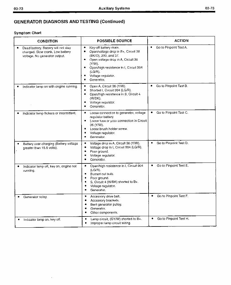
03-73 Auxiliary Systems 03-73
GENERATOR DIAGNOSIS AND TESTING (Continued)
Symptom Chart
CONDITION POSSIBLE SOURCE ACTION
l Dead battery. Battery will not stay l Key-off battery drain. l Go to Pinpoint Test A.
charged. Slow crank. Low battery l Open/voltage drop in B+, Circuit 38 voltage. No generator output. (BWO), 290, and 37.
l Open voltage drop in A, Circuit 36
ww - l Open/high resistance in I, Circuit 904
(LG/R). l Voltage regulator. l Generator.
l Indicator lamp on with engine running. l Open A, Circuit 36 (Y/W). l Go to Pinpoint Test B. l Shorted I, Circuit 904 (LGIR). l Open/high resistance in S, Circuit 4
(W/BK). l Voltage regulator. l Generator.
l Indicator lamp flickers or intermittent. l Loose connection to generator, voltage l Go to Pinpoint Test C. regulator battery.
l Loose fuse or poor connection in Circuit 36 (Y/W).
l Loose brush holder screw. l Voltage regulator. l Generator.
l Battery over-charging (Battery voltage l Voltage drop in A, Circuit 36 (Y/W). l Go to Pinpoint Test D.
greater than 15.5 volts). l Voltage drop in I, Circuit 904 (LG/R). l Poor ground. l Voltage regulator. l Generator.
l Indicator lamp off, key on, engine not l Open/high resistance in I, Circuit 904 l Go to Pinpoint Test E.
running. (LG/R). l Burned out bulb. l Poor ground. l S, Circuit 4 (W/BK) shorted to B+. l Voltage regulator. l Generator.
l Generator noisy. l Accessory drive belt. l Accessory brackets. l Bent generator pulley. l Generator. l Other components.
l Go to Pinpoint Test F.
l Indicator lamp on, key off. l Lamp circuit, (GYMI) shorted to B+. l Go to Pinpoint Test H.
l Improper lamp circuit wiring.
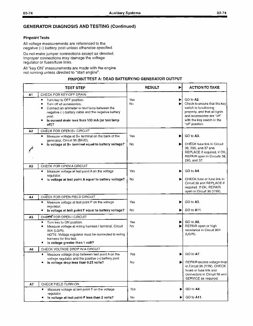
03-74 Auxiliary Systems 03-74
GENERATOR DIAGNOSIS AND TESTING (Continued)
Pinpoint Tests
All voltage measurements are referenced to the negative (-) battery post unless otherwise specified.
Do not make jumper connections except as directed. Improper connections may damage the voltage regulator or fuses/fuse links.
All “key ON” measurements are made with the engine not running unless directed to “start engine”.
PINPOINTTEST A: DEAD BATTERY/NO GENERATOR OUTPUT
TEST STEP RESULT b ACTION TO TAKE
Al CHECK FOR KEY-OFF DRAIN
l Turn key to OFF position. Yes ) GO to A2. l Turn off all accessories. No b Check to ensure that the key l Connect an ammeter or test lamp between the switch is functioning
negative (-) battery cable and the negative battery properly, and that all lights post. and accessories are “off”
l Is current drain less than 100 mA (or test lamp with the key switch in the off)? “off” position.
A2 1 CHECK FOR OPEN B+ CIRCUIT
l Measure voltage at B+ terminal on the back of the Yes ) GO to A3. generator, Circuit 38 (BWO).
l Is voltage at B+ terminal equal to battery voltage? No ) CHECK fuse link in Circuit C
% / 38,290, and 37 and
t REPLACE if required. If OK, REPAIR open in Circuits 38, 290, and 37.
A3 CHECK FOR OPEN A CIRCUIT
l Measure voltage at test point A on the voltage Yes b GO to A4.
regulator. l Is voltage at test point A equal to battery voltage? No b CHECK fuse or fuse link in
Circuit 36 and REPLACE if required. If OK, REPAIR open in Circuit 36 (Y/W).
A4 1 CHECK FOR OPEN FIELD CIRCUIT
l Measure voltage at test point F on the voltage Yes b GO to A5 regulator.
l Is voltage -at test point F equal to battery voltage? No ) GOtoAll.
A5 1 CHmFOR OPEN I CIRCUIT
l Turn key to ON position. Yes b GO to A6. l Measure voltage at wiring harness I terminal, Circuit No ) REPAIR open or high
904 (LG/R). resistance in Circuit 904 NOTE: Voltage regulator must be connected to wiring (LG/R).
harness for this test. l Is voltage greater than 1 volt?
A6 CHECK VOLTAGE DROP IN A CIRCUIT
l Measure voltage drop between test point A on the Yes ) GO to A7.
voltage regulator and the positive (+) battery post. l Is voltage drop less than 0.25 volts? No b REPAIR excess voltage drop
in Circuit 36 (Y/w). CHECK fuses or fuse link and connectors in Circuit 36 and SERVICE as required.
A7 CHECK FIELD TURN-ON
l Measure voltage at test point F on the voltage Yes b GO to AS. regulator.
l Is voltage at test point F less than 2 volts? No ) GOtoAll.
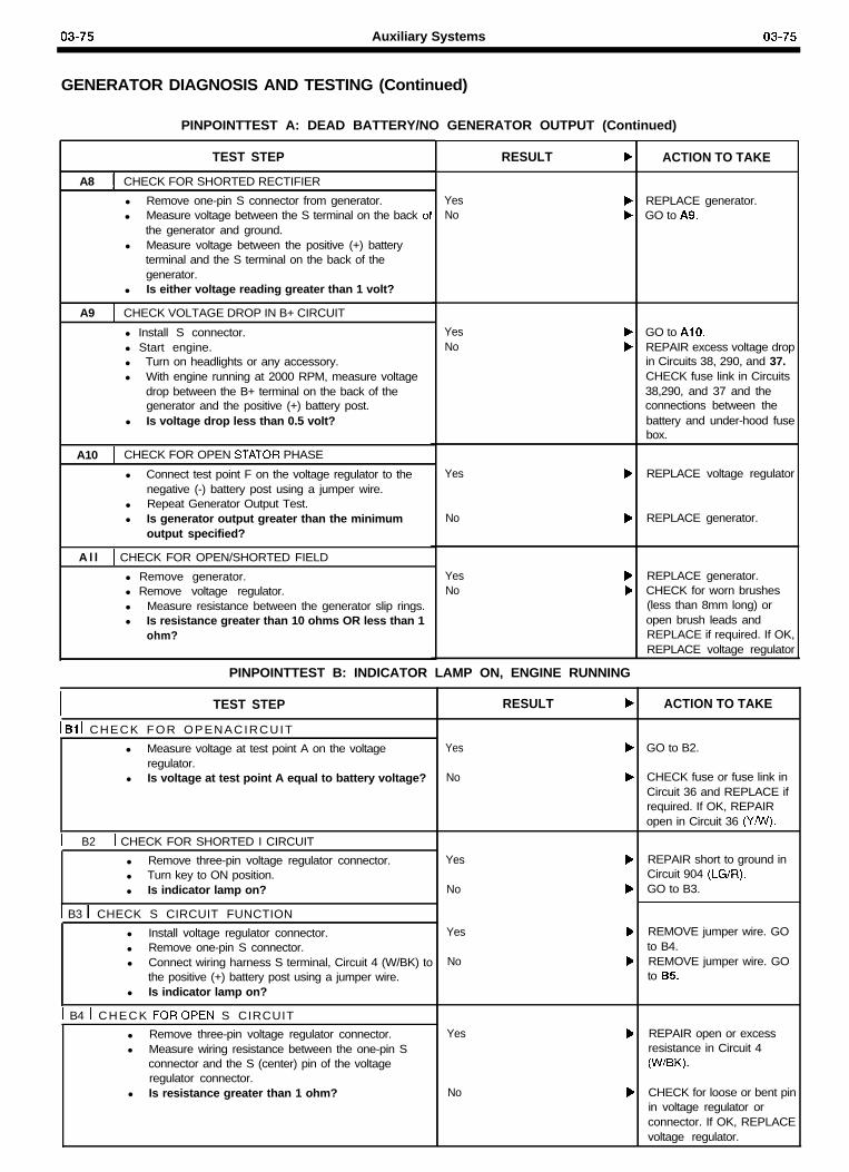
03-75 Auxiliary Systems 03-75
GENERATOR DIAGNOSIS AND TESTING (Continued)
PINPOINTTEST A: DEAD BATTERY/NO GENERATOR OUTPUT (Continued)
ACTION TO TAKETEST STEP RESULT b
A8 CHECK FOR SHORTED RECTIFIER
l Remove one-pin S connector from generator.l Measure voltage between the S terminal on the back 01
the generator and ground.l Measure voltage between the positive (+) battery
terminal and the S terminal on the back of thegenerator.
l Is either voltage reading greater than 1 volt?
A9 1 CHECK VOLTAGE DROP IN B+ CIRCUIT
l Install S connector.l Start engine.l Turn on headlights or any accessory.l With engine running at 2000 RPM, measure voltage
drop between the B+ terminal on the back of thegenerator and the positive (+) battery post.
l Is voltage drop less than 0.5 volt?
YesNo
YesNo
bb
A10 CHECK FOR OPEN STATOR PHASE
l Connect test point F on the voltage regulator to thenegative (-) battery post using a jumper wire.
l Repeat Generator Output Test.l Is generator output greater than the minimum
output specified?
Yes b
No b
A l l 1 CHECK FOR OPEN/SHORTED FIELD
l Remove generator.l Remove voltage regulator.l Measure resistance between the generator slip rings.l Is resistance greater than 10 ohms OR less than 1
ohm?
YesNo
bb
REPLACE generator.GO to A9.
GO to AlO.REPAIR excess voltage dropin Circuits 38, 290, and 37.CHECK fuse link in Circuits38,290, and 37 and theconnections between thebattery and under-hood fusebox.
REPLACE voltage regulator
REPLACE generator.
REPLACE generator.CHECK for worn brushes(less than 8mm long) oropen brush leads andREPLACE if required. If OK,REPLACE voltage regulator
PINPOINTTEST B: INDICATOR LAMP ON, ENGINE RUNNING
I TEST STEP RESULT b ACTION TO TAKE
1 Bl 1 CHECK FOR OPENACIRCUITYes
No
GO to B2.l Measure voltage at test point A on the voltageregulator.
l Is voltage at test point A equal to battery voltage? CHECK fuse or fuse link inCircuit 36 and REPLACE ifrequired. If OK, REPAIRopen in Circuit 36 (Y/w).
1 B2 1 CHECK FOR SHORTED I CIRCUITYes
No
REPAIR short to ground inCircuit 904 (LG/R).GO to B3.
l Remove three-pin voltage regulator connector.l Turn key to ON position.l Is indicator lamp on?
1 B3 1 CHECK S CIRCUIT FUNCTIONYes
No
REMOVE jumper wire. GOto B4.REMOVE jumper wire. GOto B5.
l Install voltage regulator connector.l Remove one-pin S connector.l Connect wiring harness S terminal, Circuit 4 (W/BK) to
the positive (+) battery post using a jumper wire.l Is indicator lamp on?
1 B4 1 CHECK FOROPEN S CIRCUITYes b
No b
REPAIR open or excessresistance in Circuit 4(W/BK).
l Remove three-pin voltage regulator connector.l Measure wiring resistance between the one-pin S
connector and the S (center) pin of the voltageregulator connector.
l Is resistance greater than 1 ohm? CHECK for loose or bent pinin voltage regulator orconnector. If OK, REPLACEvoltage regulator.
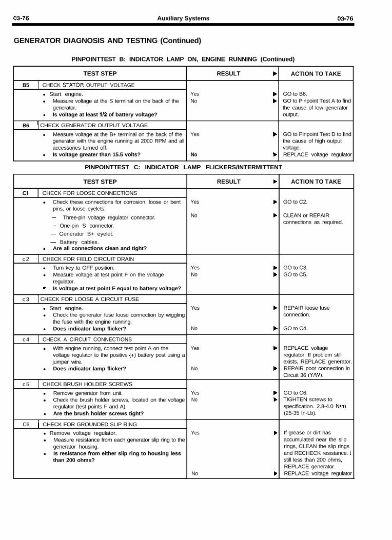
03-76 Auxiliary Systems 03-76
GENERATOR DIAGNOSIS AND TESTING (Continued)
PINPOINTTEST B: INDICATOR LAMP ON, ENGINE RUNNING (Continued)
TEST STEP RESULT b
B5 CHECK STATOR OUTPUT VOLTAGE
l Start engine. Yes bl Measure voltage at the S terminal on the back of the No b
generator.l Is voltage at least l/2 of battery voltage?
B6 1 CHECK GENERATOR OUTPUT VOLTAGE
l Measure voltage at the B+ terminal on the back of the Yes bgenerator with the engine running at 2000 RPM and allaccessories turned off.
l Is voltage greater than 15.5 volts? No b
ACTION TO TAKE
GO to B6.GO to Pinpoint Test A to findthe cause of low generatoroutput.
GO to Pinpoint Test D to findthe cause of high outputvoltage.REPLACE voltage regulator
PINPOINTTEST C: INDICATOR LAMP FLICKERS/INTERMITTENT
TEST STEP
Cl CHECK FOR LOOSE CONNECTIONS
l Check these connections for corrosion, loose or bentpins, or loose eyelets:
- Three-pin voltage regulator connector.- One-pin S connector.- Generator B+ eyelet.- Battery cables.
l Are all connections clean and tight?
c 2 CHECK FOR FIELD CIRCUIT DRAIN
l Turn key to OFF position.l Measure voltage at test point F on the voltage
regulator.+ Is voltage at test point F equal to battery voltage?
c 3 1 CHECK FOR LOOSE A CIRCUIT FUSE
l Start engine.l Check the generator fuse loose connection by wiggling
the fuse with the engine running.l Does indicator lamp flicker?
c 4 CHECK A CIRCUIT CONNECTIONS
l With engine running, connect test point A on thevoltage regulator to the positive (+) battery post using ajumper wire.
l Does indicator lamp flicker?
c 5
C6
CHECK BRUSH HOLDER SCREWS
l Remove generator from unit.l Check the brush holder screws, located on the voltage
regulator (test points F and A).l Are the brush holder screws tight?
CHECK FOR GROUNDED SLIP RING
l Remove voltage regulator.l Measure resistance from each generator slip ring to the
generator housing.l Is resistance from either slip ring to housing less
than 200 ohms?
RESULT b
Yes
No
b
b
YesNo
bb
Yes REPAIR loose fuseconnection.
No b GO to C4.
Yes b
No b
YesNo
bb
Yes b
No b
ACTION TO TAKE
GO to C2.
CLEAN or REPAIRconnections as required.
GO to C3.GO to C5.
REPLACE voltageregulator. If problem stillexists, REPLACE generator.REPAIR poor connection inCircuit 36 (Ye).
GO to C6.TIGHTEN screws tospecification. 2.8-4.0 Nom(25-35 In-Lb).
If grease or dirt hasaccumulated near the sliprings, CLEAN the slip ringsand RECHECK resistance. I<still less than 200 ohms,REPLACE generator.REPLACE voltage regulator
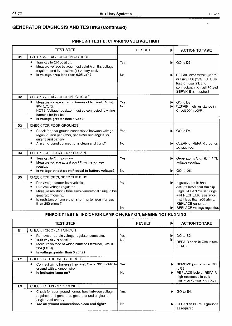
03-77 Auxiliary Systems 03-77
GENERATOR DIAGNOSIS AND TESTING (Continued)
PINPOINTTEST D: CHARGING VOLTAGE HIGH
TEST STEP I RESULT b ACTION TO TAKE
Dl I CHECK VOLTAGE DROP IN A CIRCUIT I
l Turn key to ON position. l Measure voltage between test point A on the voltage
regulator and the positive (+) battery post. l Is voltage drop less than 0.25 volt?
Yes b
No b
GO to D2.
REPAIR excess voltage drop in Circuit 36 (Y/W). CHECK fuse or fuse link and connectors in Circuit 36 and SERVICE as required.
D2 1 CHECK VOLTAGE DROP IN I CIRCUIT I
l Measure voltage at wiring harness I terminal, Circuit Yes 904 (LG/R). No NOTE: Voltage regulator must be connected to wiring harness for this test.
l Is voltage greater than 1 volt?
b b
GO to D3. REPAIR high resistance in Circuit 904 (LG/R).
03 1 CHECK FOR POOR GROUNDS I
Yes b
No b
l Check for poor ground connections between voltage regulator and generator, generator and engine, or engine and battery.
l Are all ground connections clean and tight?
GO to D4.
CLEAN or REPAIR grounds as required.
D4 1 CHECK FOR FIELD CIRCUIT DRAIN I l Turn key to OFF position. l Measure voltage at test point F on the voltage
regulator. l Is voltage at test point F equal to battery voltage?
Yes b
No b
Generator is OK. REPLACE voltage regulator.
GO to D5.
D5 1 CHECK FOR GROUNDED SLIP RING I
l Remove generator from vehicle. l Remove voltage regulator. l Measure resistance from each generator slip ring to the
generator housing. l Is resistance from either slip ring to housing less
than 200 ohms?
Yes b
No b
If grease or dirt has accumulated near the slip rings, CLEAN the slip rings and RECHECK resistance. If still less than 200 ohms, REPLACE generator. REPLACE voltage regulator
PINPOINTTEST E: INDICATOR LAMP OFF, KEY ON, ENGINE NOT RUNNING
TEST STEP RESULT b ACTION TO TAKE
I El 1 CHECK FOR OPEN I CIRCUIT I Yes No
b b
GO to E2.
REPAIR open in Circuit 904 (LG/R).
l Remove three-pin voltage regulator connector. l Turn key to ON position. l Measure voltage at wiring harness I terminal, Circuit
904 (LG/R). l Is voltage greater than 0 volts?
I E2 CHECK FOR BURNED OUT BULB I Yes
No
REMOVE jumper wire. GO to E3. REPLACE bulb or REPAIR high resistance in bulb socket or Circuit 904 (LG/R)
l Connect wiring harness I terminal, Circuit 904 (LG/R) to ground with a jumper wire.
l Is indicator lamp on?
I E3 1 CHECK FOR POOR GROUNDS I connections between voltage
regulator and generator, generator and engine, or engine and battery. Are all ground connections clean and tight?
Yes b
No b
GO to E4.
CLEAN or REPAIR grounds as required.
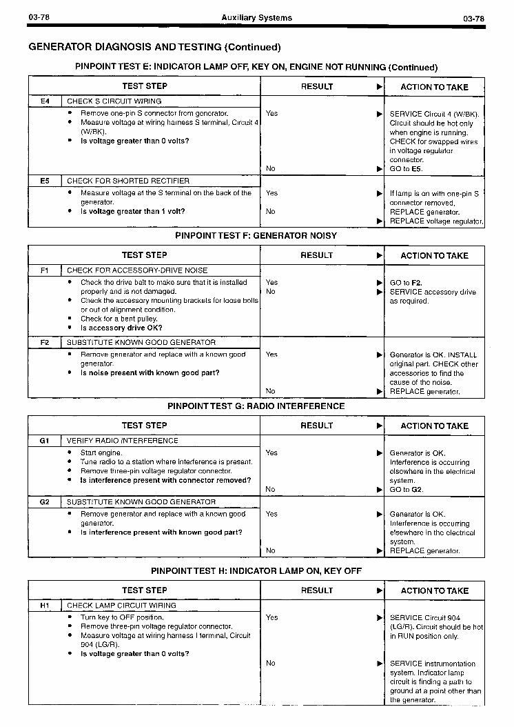
03-78 Auxiliary Systems 03-78
GENERATOR DIAGNOSIS AND TESTING (Continued)
PINPOINTTEST E: INDICATOR LAMP OFF, KEY ON, ENGINE NOT RUNNING (Continued)
TEST STEP RESULT b ACTION TO TAKE
1 E4 1 CHECKS CIRCUIT WIRING I
SERVICE Circuit 4 (W/BK). Circuit should be hot only when engine is running. CHECK for swapped wires in voltage regulator connector. GO to E5.
Yes b l Remove one-pin S connector from generator. l Measure voltage at wiring harness S terminal, Circuit 4
(W/BK). l Is voltage greater than 0 volts?
I No b
1 E5 1 CHECK FOR SHORTED RECTIFIER I Yes If lamp is on with one-pin S
connector removed, REPLACE generator. REPLACE voltage regulator.
l Measure voltage at the S terminal on the back of the generator.
l Is voltage greater than I volt? No b
PINPOINTTEST F: GENERATOR NOISY
I TEST STEP RESULT ACTION TO TAKE
I Fl 1 CHECK FOR ACCESSORY-DRIVE NOISE
l Check the drive belt to make sure that it is installed properly and is not damaged.
l Check the accessory mounting brackets for loose bolts or out of alignment condition.
l Check for a bent pulley. l Is accessory drive OK?
Yes No
GO to F2. SERVICE accessory drive as required.
I F2 1 SUBSTITUTE KNOWN GOOD GENERATOR
Yes b
No b
Generator is OK. INSTALL original part. CHECK other accessories to find the cause of the noise. REPLACE generator.
l Remove generator and replace with a known good generator.
l Is noise present with known good part?
PINPOINT TEST G: RADIO INTERFERENCE
TEST STEP RESULT b
Gl 1 VERIFY RADIO INTERFERENCE
ACTION TO TAKE
Generator is OK. Interference is occurring elsewhere in the electrical system. GO to G2.
l Start engine. Yes b l Tune radio to a station where interference is present. l Remove three-pin voltage regulator connector. l Is interference present with connector removed?
No b
G2 1 SUBSTITUTE KNOWN GOOD GENERATOR
Yes
No b
Generator is OK. Interference is occurring elsewhere in the electrical system. REPLACE generator.
l Remove generator and replace with a known good generator.
l Is interference present with known good part?
PINPOINTTEST H: INDICATOR LAMP ON, KEY OFF
TEST STEP RESULT b ACTION TO TAKE
HI 1 CHECK LAMP CIRCUIT WIRING
l Turn key to OFF position. l Remove three-pin voltage regulator connector. l Measure voltage at wiring harness I terminal, Circuit
904 (LG/R). l Is voltage greater than 0 volts?
Yes
No b
SERVICE Circuit 904 (LG/R). Circuit should be hot in RUN position only.
SERVICE instrumentation system. Indicator lamp circuit is finding a path to ground at a point other than the generator.
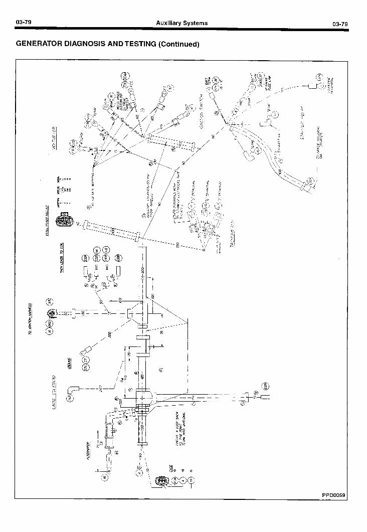
03-79 Auxiliary Systems
GENERATOR DIAGNOSIS ANDTESTING (Continued)
?I\ 0
0 4 $I s ? 9 V
\
\
PPD0059
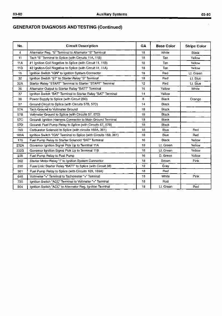
03-80 Auxiliary Systems 03-80
GENERATOR DIAGNOSIS AND TESTING (Continued)
No I . Circuit Description I GA I Base Color I Stripe Color I 4 1 Alternator Reg. “S” Terminal to Alternator “S” Terminal I 18 I--- White I Black I
11 1 Tach “S” Terminal to Splice (with Circuits 11 A, 11 B) I 18 1 Tan I Yellow I 1 IA I #I Ignition Coil Negative to Splice (with Circuit 11, 11 B) I 18 I Tan I Yellow I 11 B I #2 Ignition Coil Negative to Splice (with Circuit 11, 11 A) I ‘8 I Tan I Yellow I 16 I Ignition Switch “IGN” to Ignition System Connector I 18 I Red I Lt. Green I
32 I Ignition Switch “ST” to Starter Relay “S” Terminal I ‘8 I Red I Lt. Blue I 32A I Starter Relay “START” Terminal to Starter “START” Terminal I 12 I Red I Lt. Blue I 36 I Alternator Output to Starter Relay “BATT” Terminal I ‘6 I Yellow I White I 37 I Ignition Switch “BAT” Terminal to Starter Relay “BAT” Terminal I 14 I Yellow I I 38 [ Power Supply to Splice (with Circuit 290) 1 8 1 Black ! Orange
57 I Ground Circuit to Splice (with Circuits 57B, 57D) I ‘4 I Black I I 57A I Tach Ground to Voltmeter Ground I 18 1 Black I I 578 I Voltmeter Ground to Splice (with Circuits 57, 57D) I ‘8 I Black I I 57C I Ground: Ignition Harness Connector to Main Ground Terminal I ‘8 I Black I I 570 I Ground: Fuel Pump Relay to Splice (with Circuits 57, 57B) I 18 I Black I I 169 I Carburetor Solenoid to Splice (with circuits 169A, 361) I ‘8 I Blue I Red I
169A 1 Ignition Switch “IGN” Terminal to Splice (with Circuits 169, 361) I 18 1 Blue I Red I 175 I Fuel Pump Relay to Starter Solenoid “BAT” Terminal I ‘6 I Black I Yellow I
232A 1 Governor Ignition Signal Pick Up to Terminal IIA I ‘8 I Lt. Green I Yellow I 2328 I Governor Ignition Signal Pick Up to Terminal 11 B I ‘8 I Lt. Green I Yellow I 238 bel Pump Relay to Fuel Pump I 16 I D. Green I Yellow I 262 I Starter Motor Relay “I” to Ignition System Connector I ‘8 I Brown I Pink I 290 I Fuse Link: Starter Relay “BATT” to Splice (with Circuit 38) I 12 I Gray I I 361 I Fuel Pump Relay to Splice (with Circuits 169, 169A) I ‘8 I Red I I 648 I Voltmeter “+” Terminal to Tachometer “+” Terminal I 18 I White I Pink I 730 I Ignition Switch “ACC” Terminal to Voltmeter “+” Terminal I ‘8 I Red I I 904 1 Ignition Switch “ACC” to Alternator Reg. Ignition Terminal I 18 1 Lt. Green I Red I
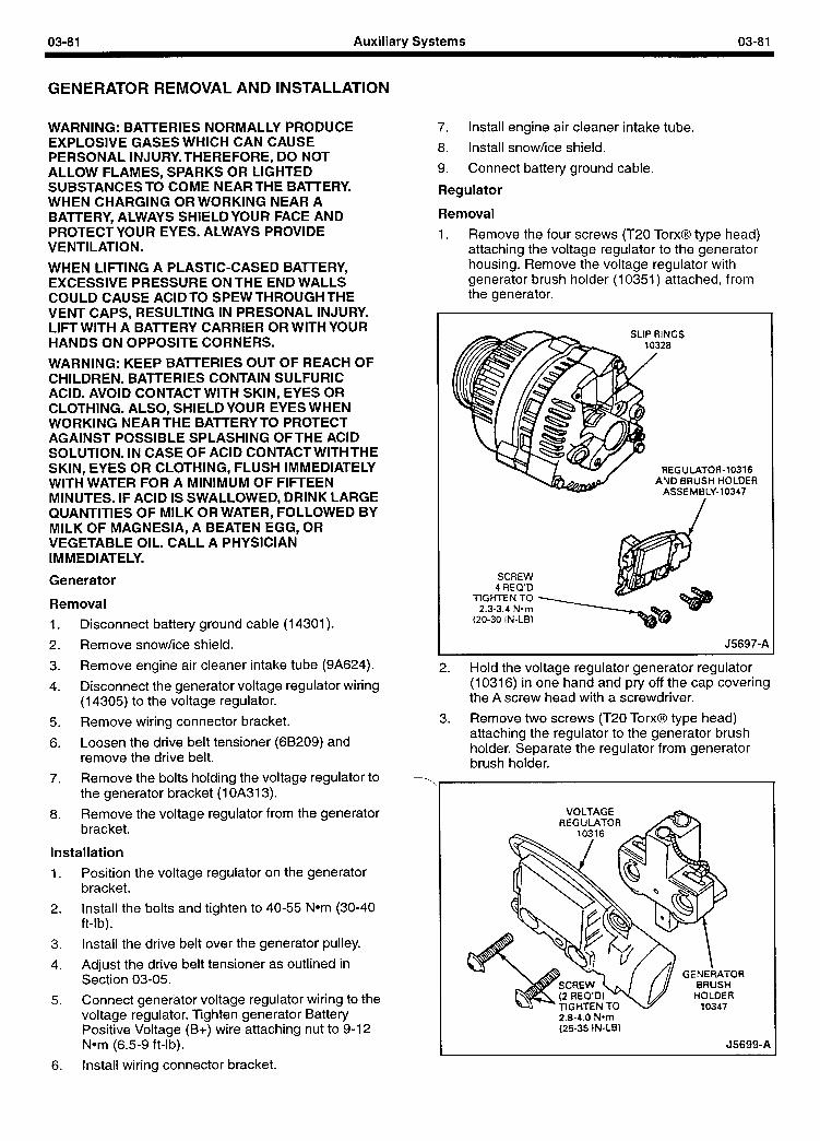
03-81 Auxiliary Systems 03-81
GENERATOR REMOVAL AND INSTALLATION
WARNING: BAnERlES NORMALLY PRODUCE EXPLOSIVE GASES WHICH CAN CAUSE PERSONAL INJURY.THEREFORE, DO NOT ALLOW FLAMES, SPARKS OR LIGHTED SUBSTANCES TO COME NEAR THE BATTERY. WHEN CHARGING OR WORKING NEAR A BATTERY, ALWAYS SHIELDYOUR FACE AND PROTECTYOUR EYES. ALWAYS PROVIDE VENTILATION.
WHEN LIFTING A PLASTIC-CASED BATTERY, EXCESSIVE PRESSURE ONTHE END WALLS COULD CAUSE ACIDTO SPEW THROUGH THE VENT CAPS, RESULTING IN PRESONAL INJURY. LIFT WITH A BATTERY CARRIER OR WITH YOUR HANDS ON OPPOSITE CORNERS.
WARNING: KEEP BATTERIES OUT OF REACH OF CHILDREN. BATTERIES CONTAIN SULFURIC ACID. AVOID CONTACT WITH SKIN, EYES OR CLOTHING. ALSO, SHIELD YOUR EYES WHEN WORKING NEAR THE BATTERY TO PROTECT AGAINST POSSIBLE SPLASHING OFTHE ACID SOLUTION. IN CASE OF ACID CONTACT WITHTHE SKIN, EYES OR CLOTHING, FLUSH IMMEDIATELY WITH WATER FOR A MINIMUM OF FIFTEEN MINUTES. IF ACID IS SWALLOWED, DRINK LARGE QUANTITIES OF MILK OR WATER, FOLLOWED BY MILK OF MAGNESIA, A BEATEN EGG, OR VEGETABLE OIL. CALL A PHYSICIAN IMMEDIATELY.
Generator
Removal
1. Disconnect battery ground cable (14301).
2. Remove snow/ice shield.
3. Remove engine air cleaner intake tube (9A624).
4. Disconnect the generator voltage regulator wiring (14305) to the voltage regulator.
5. Remove wiring connector bracket.
6. Loosen the drive belt tensioner (68209) and remove the drive belt.
7. Remove the bolts holding the voltage regulator to the generator bracket (1 OA313).
8. Remove the voltage regulator from the generator bracket.
Installation
1. Position the voltage regulator on the generator bracket.
2. Install the bolts and tighten to 40-55 Nom (30-40 ft-lb).
3. Install the drive belt over the generator pulley.
4. Adjust the drive belt tensioner as outlined in Section 03-05.
5. Connect generator voltage regulator wiring to the voltage regulator. Tighten generator Battery Positive Voltage (B+) wire attaching nut to 9-12 Nom (6.5-9 ft-lb).
6. Install wiring connector bracket.
7. Install engine air cleaner intake tube.
8. Install snow/ice shield.
9. Connect battery ground cable.
Regulator
Removal
1. Remove the four screws (T20 TorxO type head) attaching the voltage regulator to the generator housing. Remove the voltage regulator with generator brush holder (10351) attached, from the generator.
SLIP RINGS
REGUUTOR-10316 AND BRUSH HOLDER
ASSEMBLY-10347
SCREW 4 REQ’D
TIGHTEN TO 2.3-3.4 N-m
(20-30 IN-LB)
J5697-A
2. Hold the voltage regulator generator regulator (10316) in one hand and pry off the cap covering the A screw head with a screwdriver.
3. Remove two screws (T20 TorxO type head) attaching the regulator to the generator brush holder. Separate the regulator from generator brush holder.
VOLTAGE REGULATOR
2.8-4.0 Nom (25-35 IN-LB)
J569 19-A
03-82 Auxiliary Systems 03-82
GENERATOR REMOVAL AND INSTALLATION (Continued)
Installation
Replace generator brush holder to voltage regulator and install attaching screws.
Replace cap on the head of the A terminal screw.
Depress the generator brushes into the generator brush holder.
l Hold the generator brushes in position by inserting a standard size paper clip (or equivalent) through both the location hole in the voltage regulator and through the holes in the generator brush holders.
Install the voltage regulator and generator brush holder to the generator with attaching screws.
l Remove paper clip (or equivalent) from the regulator.
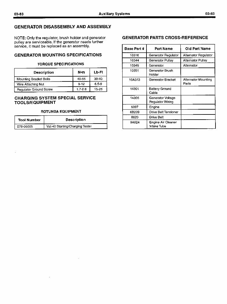
03-83 Auxiliary Systems 03-83
GENERATOR DISASSEMBLY AND ASSEMBLY
NOTE: Only the regulator, brush holder and generator pulley are serviceable. If the generator needs further service, it must be replaced as an assembly.
GENERATOR MOUNTING SPECIFICATIONS
TORQUE SPECIFICATIONS
GENERATOR PARTS CROSS-REFERENCE
Base Part # Part Name Old Part Name
10316 Generator Regulator Alternator Regulator
10344 Generator Pulley Alternator Pulley
10346 Generator Alternator
Description Nom Lb-Ft
Mounting Bracket Bolts 40-55 30-40 Wire Attaching Nut 9-12 6.5-9
Regulator Ground Screw 1.7-2.8 15-25
10351
1 OA313
14301
Generator Brush Holder
Generator Bracket
Battery Ground Cable
Alternator Mounting Parts
CHARGING SYSTEM SPECIAL SERVICE TOOLS/EQUIPMENT
ROTUNDA EQUIPMENT
I 14305 1 Generator Voltage 1 I
6007
68209
Regulator Wiring
Engine
Drive Belt Tensioner
Tool Number Description I 8620 1 Drive Belt I I
r 1 Engine Air Cleaner 1 I 078-00005 Vat-40 Starting/Charging Tester I I Intake Tube I I