1 version 2.3 - anolis lighting
TRANSCRIPT

1
Version 2.3

2
Table of contents
1. Safety instructions ......................................................................................................... 32. Fixture exterior view ...................................................................................................... 53. Installation....................................................................................................................... 6
3.1 Connection to the mains ............................................................................................ 63.2 Rigging the fixture ...................................................................................................... 73.3 Ceiling mounting kit installation ................................................................................. 83.4 Positioning the Robin ProMotion ............................................................................... 93.5 Additional base covers installation ......................................................................... 113.6 Installing the wide-angle lens .................................................................................. 123.7 Installing the Automatic Distance Meter (ADM) ....................................................... 133.8 DMX-512 connection ................................................................................................ 163.9 Ethernet connection ................................................................................................. 173.10 Wireless DMX operation ........................................................................................ 18
4. Control menu map ........................................................................................................ 195. Control menu ............................................................................................................... 22
5.1 Addressing ............................................................................................................... 225.2 Information .............................................................................................................. 235.3 Personality.................................................................................................................245.4 Manual Control ......................................................................................................... 255.5 Stand- alone ............................................................................................................. 265.6 User Media ............................................................................................................... 275.7 Service ..................................................................................................................... 29
6. Keystones ..................................................................................................................... 307. Using external HDMI input ........................................................................................... 328. Ways of file transfer from/to the ProMotion ............................................................... 329. NAS operation ............................................................................................................... 3610. Software update of the fixture ................................................................................... 3711. RDM.............................................................................................................................. 3812. Error and information messages .............................................................................. 3913. Technical Specifications ............................................................................................ 4014. Maintenance and cleaning ......................................................................................... 44
14.1 Replacing a fuse .................................................................................................... 4515. ChangeLog ................................................................................................................. 45
Robin ProMotion
3
FOR YOUR OWN SAFETY, PLEASE READ THIS USER MANUAL CAREFULLYBEFORE POWERING OR INSTALLING YOUR ROBIN ProMotion !
Save it for future reference.
This device has left our premises in absolutely perfect condition. In order to maintain this condition and to en-sure a safe operation, it is absolutely necessary for the user to follow the safety instructions and warning notes written in this manual.
The manufacturer will not accept liability for any resulting damages caused by the non-observance of this manual or any unauthorized modification to the device.
Please consider that damages caused by manual modifications to the device are not subject to warranty.
The Robin ProMotion was designed for indoor use and it is intended for professional application only. It is not for household use.
1. Safety instructions
DANGEROUS VOLTAGE CONSTITUTING A RISK OF ELECTRIC SHOCK IS PRESENT WITHIN THIS UNIT!
Make sure that the available voltage is not higher than stated on the rear panel of the fixture.This fixture should be operated only from the type of power source indicated on the marking label. If you are not sure of the type of power supplied, consult your authorized distributor or local power company.
Always disconnect the fixture from AC power before cleaning, removing or installing the fuses, or any part.
The power plug has to be accessible after installing the fixture. Do not overload wall outlets and extension cords as this can result in fire or electric shock.
Do not allow anything to rest on the power cord. Do not locate this fixture where the cord may be damaged by persons walking on it.
Make sure that the power cord is never crimped or damaged by sharp edges. Check the fixture and the power cord from time to time.
Refer servicing to qualified service personnel.
This fixture falls under protection class I. Therefore this fixture has to be connected to a mains socket outlet with a protective earthing connection.
Do not connect this fixture to a dimmer pack.
LED light emission. Risk of eye injury. Do not look into the beam at short distance from the product. Do not view the light output with optical instruments or any device that
may concentrate the beam
If the fixture has been exposed to drastic temperature fluctuation (e.g. after transportation), do not switch it on immediately. The arising condensation water might damage your device. Leave the device switched off until it has reached room temperature.
Do not shake the fixture. Avoid brute force when installing or operating the fixture.This fixture was designed for indoor use only, do not expose this unit to rain or use near water.
When choosing the installation spot, please make sure that the fixture is not exposed to extreme heat, moisture, dust or entertainment smoke (haze)
4
Air vents and slots in the fixture head and base are provided for ventilation to ensure reliable operation of the device and to protect it from overheating.
Do not block the light output with any object when the fixture is under operation.
The openings should never be covered with cloth or other materials, and never must be blocked.
This fixture should not be placed in a built-in installation unless proper ventilation is provided.
Only operate the fixture after having checked that the housing is firmly closed and all screws are tightly fastened.
Always use a secondary safety cable when mounting this fixture.
Do not block the front objective with any object when the fixture is under operation.
The fixture becomes very hot during operation. Allow the fixture to cool approximately 20 minutes prior to ma-nipulate with it.
Operate the fixture only after having familiarized with its functions. Do not permit operation by persons not qualified for operating the fixture. Most damages are the result of unprofessional operation!
Please use the original packaging if the fixture is to be transported.
Please consider that unauthorized modifications on the fixture are forbidden due to safety reasons!
If this device will be operated in any way different to the one described in this manual, the product may suffer damages and the guarantee becomes void. Furthermore, any other operation may lead to dangers like short-cir-cuit, burns, electric shock, crash etc.
Immunity of the equipment is designed for electromagnetic environments E1, E2, E3 according to the stand-ard EN55103-2 ed.2 Electromagnetic compatibility. Product family standard for audio, video, audiovisual and entertainment lighting control apparatus for professional use. Part 2: Immunity.The product (covers and cables) must not be exposed to a high frequency electromagnetic field higher than 3V/m
The installation company should check levels of possible interferences above the tested levels E1,E2,E3 given by this standard (e.g. transmitters in surrounding area) before installing the equipment. Emission of the equipment complies with the standard EN55032 Electromagnetic compatibility of multimedia equipment – Emission Requirements according to class B.
To avoid damage of the internal optical system of the fixture, never let the sunlight or other fixture lights directly to the front lens , even when the fixture is not working !
Warning for the ProMotion ADM (ADM = Automatic Distance Meter) only:
LASER DEVICE CLASS 1
5
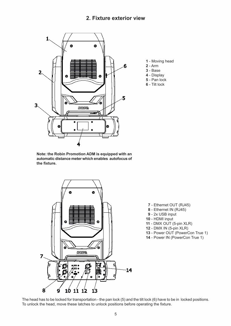
2. Fixture exterior view
7 - Ethernet OUT (RJ45)8 - Ethernet IN (RJ45)
9 - 2x USB input10 - HDMI input 11 - DMX OUT (5-pin XLR)12 - DMX IN (5-pin XLR)13 - Power OUT (PowerCon True 1) 14 - Power IN (PowerCon True 1)
1 - Moving head2 - Arm3 - Base 4 - Display5 - Pan lock6 - Tilt lock
The head has to be locked for transportation - the pan lock (5) and the tilt lock (6) have to be in locked positions. To unlock the head, move these latches to unlock positions before operating the fixture.
Note: the Robin Promotion ADM is equipped with an automatic distance meter which enables autofocus ofthe fixture.
6
3. Installation Fixtures must be installed by a qualified electrician in accordance with all
national and local electrical and construction codes and regulations.
3.1 Connection to the mains
For protection from electric shock, the fixture must be earthed!
The Robin ProMotion is equipped with auto-switching power supply that automatically adjusts to any 50-60Hz AC power source from 100-240 Volts.
Install a suitable plug on the power cord (if it is needed), note that the cores in the power cord are coloured according to the following table. The earth has to be connected!If you have any doubts about proper installation, consult a qualified electrician.
Core (EU) Core (US) Connection Plug Terminal Marking
Brown Black Live L
Light blue White Neutral N
Yellow/Green Green Earth
This device falls under class one and must be earthed (grounded)!
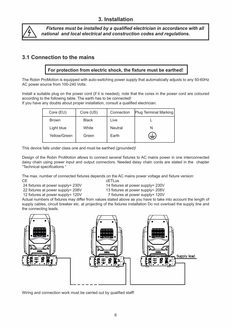
Design of the Robin ProMotion allows to connect several fixtures to AC mains power in one interconnected daisy chain using power input and output connectors. Needed daisy chain cords are stated in the chapter “Technical specifications “
The max. number of connected fixtures depends on the AC mains power voltage and fixture version: CE cETLus 24 fixtures at power supply= 230V 14 fixtures at power supply= 230V 22 fixtures at power supply= 208V 13 fixtures at power supply= 208V 12 fixtures at power supply= 120V 7 fixtures at power supply= 120VActual numbers of fixtures may differ from values stated above as you have to take into account the length of supply cables, circuit breaker etc. at projecting of the fixtures installation Do not overload the supply line and the connecting leads.
Do not overload the supply line and the connecting leads.
Wiring and connection work must be carried out by qualified staff!
7
3.2 Rigging the fixture
A structure intended for installation of the fixture (s) must safely hold weight of the fixture(s) placed on it. The structure has to be certificated to the purpose.
The fixture (fixtures) must be installed in accordance with national and local electrical and construction codes and regulation.
For overhead installation, the fixture must be always secured with a safety wire
When rigging, derigging or servicing the fixture staying in the area below the installation place, on bridges, under high working places and other endangered areas is forbidden.
The operator has to make sure that safety-relating and machine-technical installations are approved by an expert before taking into operation for the first time and after changes before taking into operation another time.
The operator has to make sure that safety-relating and machine-technical installations are approved by a skilled person once a year.
Allow the fixture to cool for ten minutes before handling.
The projector should be installed outside areas where persons may walk by or be seated.
IMPORTANT! OVERHEAD RIGGING REQUIRES EXTENSIVE EXPERIENCE, including calculating working load limits, installation material being used, and periodic safety inspection of all installation materials and the projector. If you lack these qualifications, do not attempt the installation yourself, but use a help of professional companies.
CAUTION: Fixtures may cause severe injuries when crashing down! If you have doubts concerning the safety of a possible installation, do not install the fixture!
The fixture has to be installed out of the reach of public.
The fixture must never be fixed swinging freely in the room.
When installing the device, make sure there is no highly inflammable material (decoration articles, etc.) in a distance of min. 0.5 m.
CAUTION! Use an appropriate clamp to rig the fixture on the truss. Follow the instructions mentioned at the bottom of the base.
Make sure that the device is fixed properly! Ensure that the structure (truss) to which you are attaching the fixtures is secure.
The fixture can be placed directly on the stage floor or rigged on a truss without altering its operation characte-ristics .
For securing the fixture a truss install a safety wire that can hold at least 10 times the weight of the fixture. Use only the safety wire with snap hooks with screw lock gates. Fasten the safety cable in the attachment point and around the truss as shown on the picture.
.
8
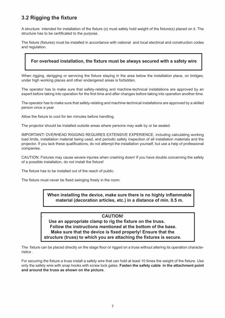
Rigging via two omega holders:
1-Clamp2-Omega holders with quarter-turn loks3-Truss4- Safety wire5-Attachment point for safety wire
When installing fixtures side-by-side, avoid illuminating one fixture with another!
3.3 Ceiling mounting kit installation The ceiling mounting kit (optional) allows you to fasten the Robin Promotion directly on the ceiling or the wall. The ceiling mounting kit includes mounting plate and four quick-lock fasteners.
The ceiling (wall) intended for installation of the fixture(s) must safely hold weight of the fixture(s) placed on it.
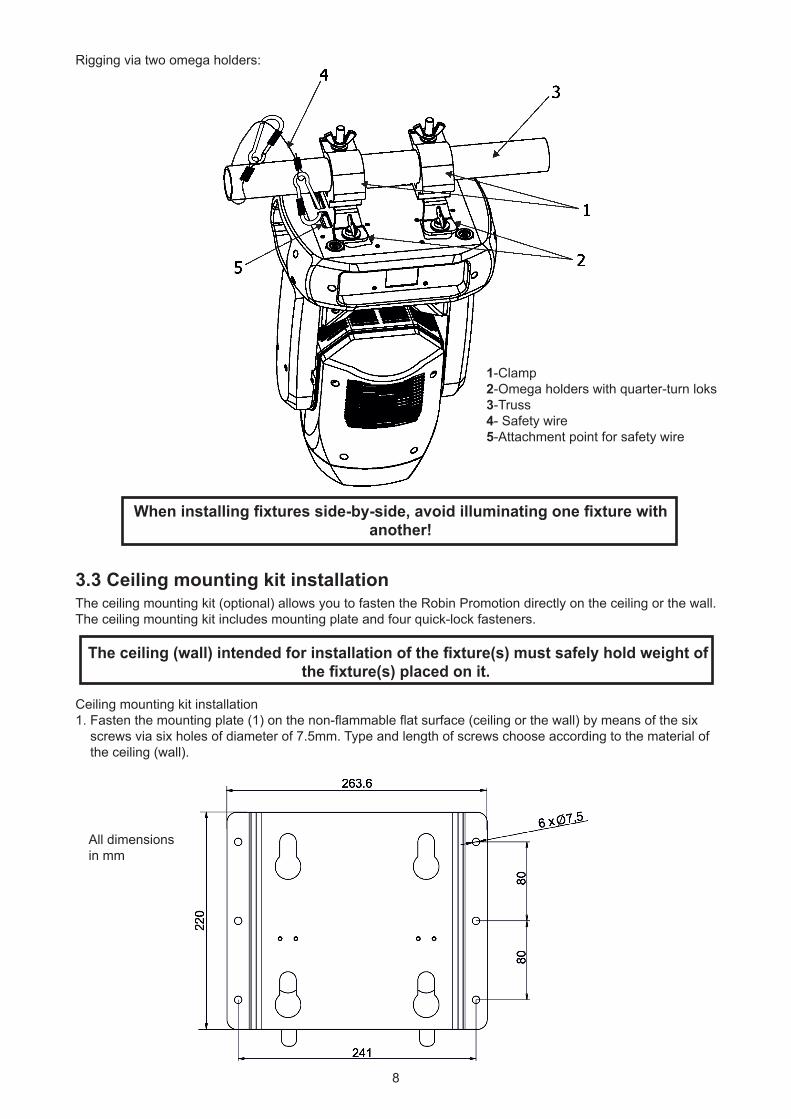
Ceiling mounting kit installation1. Fasten the mounting plate (1) on the non-flammable flat surface (ceiling or the wall) by means of the six screws via six holes of diameter of 7.5mm. Type and length of screws choose according to the material of the ceiling (wall).
All dimensions in mm
9
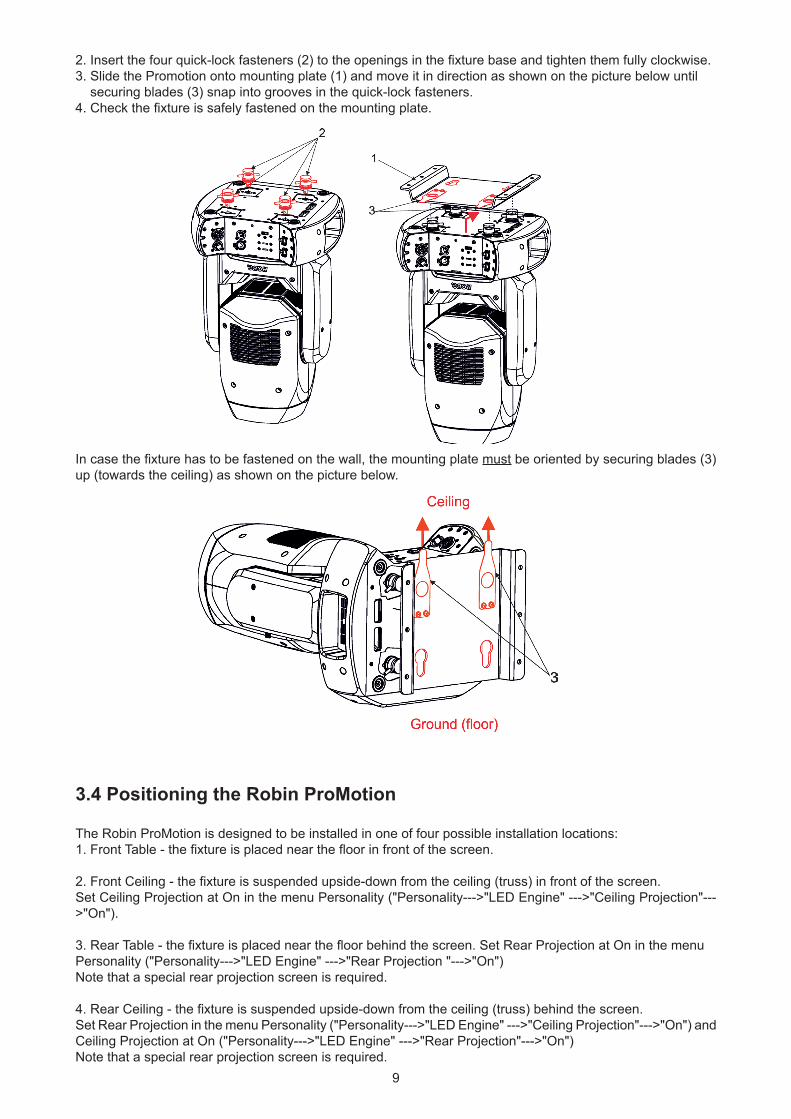
2. Insert the four quick-lock fasteners (2) to the openings in the fixture base and tighten them fully clockwise.3. Slide the Promotion onto mounting plate (1) and move it in direction as shown on the picture below until securing blades (3) snap into grooves in the quick-lock fasteners.4. Check the fixture is safely fastened on the mounting plate.
In case the fixture has to be fastened on the wall, the mounting plate must be oriented by securing blades (3) up (towards the ceiling) as shown on the picture below.
3.4 Positioning the Robin ProMotion
The Robin ProMotion is designed to be installed in one of four possible installation locations:1. Front Table - the fixture is placed near the floor in front of the screen.
2. Front Ceiling - the fixture is suspended upside-down from the ceiling (truss) in front of the screen.Set Ceiling Projection at On in the menu Personality ("Personality--->"LED Engine" --->"Ceiling Projection"--->"On").
3. Rear Table - the fixture is placed near the floor behind the screen. Set Rear Projection at On in the menuPersonality ("Personality--->"LED Engine" --->"Rear Projection "--->"On")Note that a special rear projection screen is required.
4. Rear Ceiling - the fixture is suspended upside-down from the ceiling (truss) behind the screen.Set Rear Projection in the menu Personality ("Personality--->"LED Engine" --->"Ceiling Projection"--->"On") and Ceiling Projection at On ("Personality--->"LED Engine" --->"Rear Projection"--->"On")Note that a special rear projection screen is required.
10
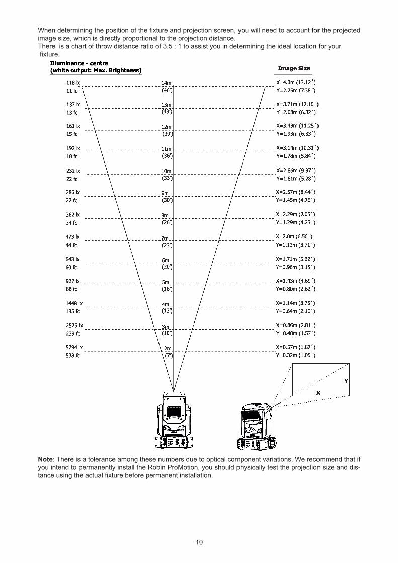
Note: There is a tolerance among these numbers due to optical component variations. We recommend that if you intend to permanently install the Robin ProMotion, you should physically test the projection size and dis-tance using the actual fixture before permanent installation.
When determining the position of the fixture and projection screen, you will need to account for the projected image size, which is directly proportional to the projection distance.There is a chart of throw distance ratio of 3.5 : 1 to assist you in determining the ideal location for your fixture.
11
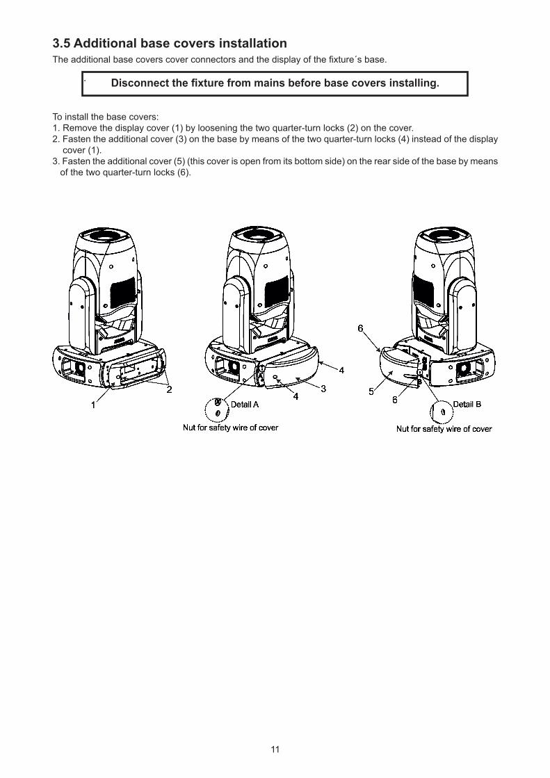
3.5 Additional base covers installation The additional base covers cover connectors and the display of the fixture´s base.
Disconnect the fixture from mains before base covers installing.
To install the base covers:1. Remove the display cover (1) by loosening the two quarter-turn locks (2) on the cover.2. Fasten the additional cover (3) on the base by means of the two quarter-turn locks (4) instead of the display cover (1).3. Fasten the additional cover (5) (this cover is open from its bottom side) on the rear side of the base by means of the two quarter-turn locks (6).
.
12
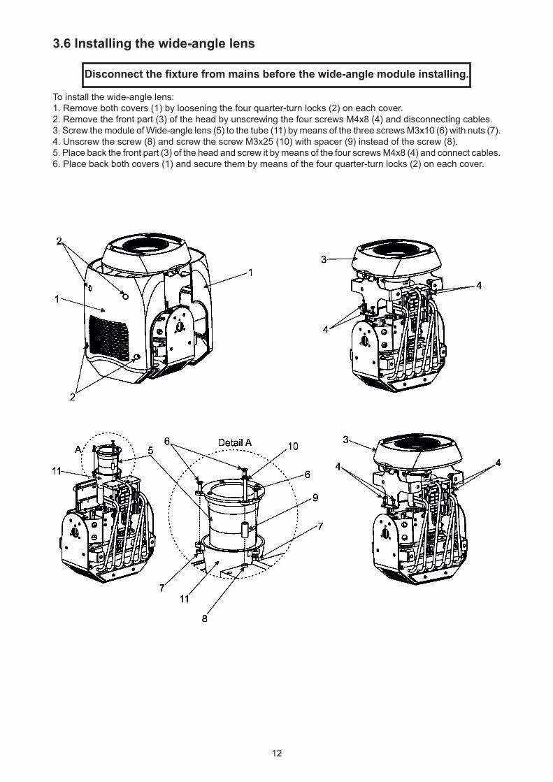
3.6 Installing the wide-angle lens
Disconnect the fixture from mains before the wide-angle module installing.
To install the wide-angle lens:1. Remove both covers (1) by loosening the four quarter-turn locks (2) on each cover.2. Remove the front part (3) of the head by unscrewing the four screws M4x8 (4) and disconnecting cables.3. Screw the module of Wide-angle lens (5) to the tube (11) by means of the three screws M3x10 (6) with nuts (7).4. Unscrew the screw (8) and screw the screw M3x25 (10) with spacer (9) instead of the screw (8).5. Place back the front part (3) of the head and screw it by means of the four screws M4x8 (4) and connect cables.6. Place back both covers (1) and secure them by means of the four quarter-turn locks (2) on each cover.
13
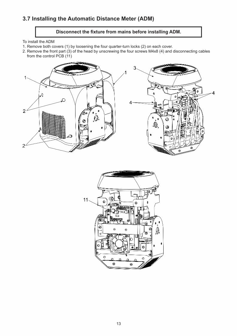
3.7 Installing the Automatic Distance Meter (ADM)
Disconnect the fixture from mains before installing ADM.
To install the ADM 1. Remove both covers (1) by loosening the four quarter-turn locks (2) on each cover.2. Remove the front part (3) of the head by unscrewing the four screws M4x8 (4) and disconnecting cables from the control PCB (11)
14
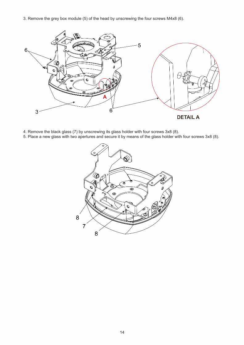
3. Remove the grey box module (5) of the head by unscrewing the four screws M4x8 (6).
4. Remove the black glass (7) by unscrewing its glass holder with four screws 3x8 (8).5. Place a new glass with two apertures and secure it by means of the glass holder with four screws 3x8 (8).
15
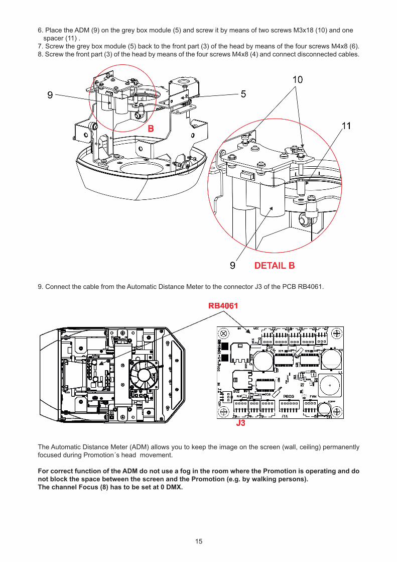
6. Place the ADM (9) on the grey box module (5) and screw it by means of two screws M3x18 (10) and one spacer (11) .7. Screw the grey box module (5) back to the front part (3) of the head by means of the four screws M4x8 (6).8. Screw the front part (3) of the head by means of the four screws M4x8 (4) and connect disconnected cables.
9. Connect the cable from the Automatic Distance Meter to the connector J3 of the PCB RB4061.
The Automatic Distance Meter (ADM) allows you to keep the image on the screen (wall, ceiling) permanently focused during Promotion´s head movement.
For correct function of the ADM do not use a fog in the room where the Promotion is operating and do not block the space between the screen and the Promotion (e.g. by walking persons). The channel Focus (8) has to be set at 0 DMX.
16
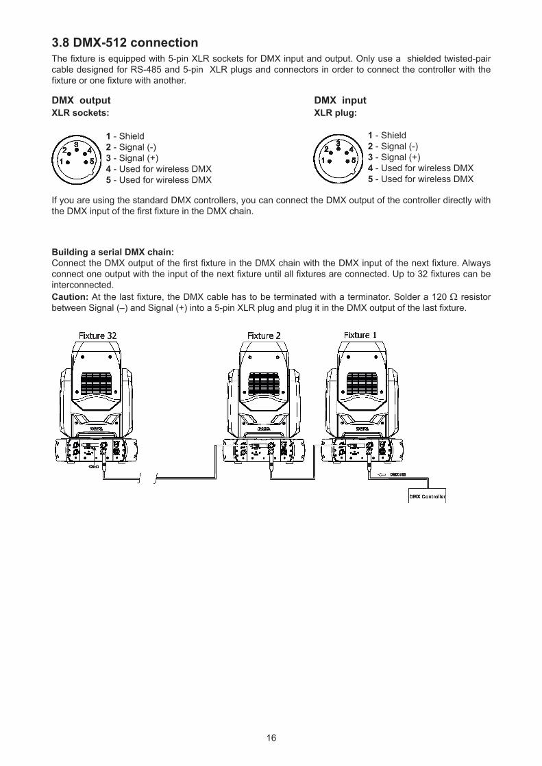
3.8 DMX-512 connectionThe fixture is equipped with 5-pin XLR sockets for DMX input and output. Only use a shielded twisted-pair cable designed for RS-485 and 5-pin XLR plugs and connectors in order to connect the controller with the fixture or one fixture with another.
DMX output DMX inputXLR sockets: XLR plug:
If you are using the standard DMX controllers, you can connect the DMX output of the controller directly with the DMX input of the first fixture in the DMX chain.
Building a serial DMX chain:Connect the DMX output of the first fixture in the DMX chain with the DMX input of the next fixture. Always connect one output with the input of the next fixture until all fixtures are connected. Up to 32 fixtures can be interconnected.Caution: At the last fixture, the DMX cable has to be terminated with a terminator. Solder a 120 Ω resistor between Signal (–) and Signal (+) into a 5-pin XLR plug and plug it in the DMX output of the last fixture.
1 - Shield2 - Signal (-)3 - Signal (+)4 - Used for wireless DMX5 - Used for wireless DMX
1 - Shield2 - Signal (-)3 - Signal (+)4 - Used for wireless DMX5 - Used for wireless DMX
17
3.9 Ethernet connectionThe fixtures on a data link are connected to the Ethernet with ArtNet communication protocol.The control soft-ware running on your PC (or light console) has to support Art-Net protocol.Art-Net communication protocol is a 10 Base T Ethernet protocol based on the TCP/IP.Its purpose is to allow transfer of large amounts of DMX 512 data over a wide area using standard network technology.
IP address is the Internet protocol address.The IP uniquely identifies any node (fixture) on a network.The Universe is a single DMX 512 frame of 512 channels.
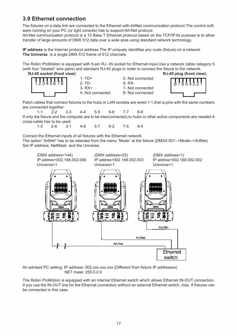
The Robin ProMotion is equipped with 8-pin RJ- 45 socket for Ethernet input.Use a network cable category 5 (with four “twisted” wire pairs) and standard RJ-45 plugs in order to connect the fixture to the network. RJ-45 socket (front view): RJ-45 plug (front view): 1- TD+ 5- Not connected 2- TD- 6- RX- 3- RX+ 7- Not connected 4- Not connected 8- Not connected
Patch cables that connect fixtures to the hubs or LAN sockets are wired 1:1,that is,pins with the same numbers are connected together: 1-1 2-2 3-3 4-4 5-5 6-6 7-7 8-8 If only the fixture and the computer are to be interconnected,no hubs or other active components are needed.A cross-cable has to be used: 1-3 2-6 3-1 4-8 5-7 6-2 7-5 8-4
Connect the Ethernet inputs of all fixtures with the Ethernet network.The option “ArtNet" has to be selected from the menu “Mode” at the fixture (DMXA 001-->Mode-->ArtNet).Set IP address, NetMask and the Universe.
(DMX address=144) (DMX address=25) (DMX address=1) IP addres=002.168.002.006 IP addres=002.168.002.003 IP addres=002.168.002.002 Universe=1 Universe=1 Universe=1
An advised PC setting: IP address: 002.xxx.xxx.xxx (Different from fixture IP addresses) NET mask: 255.0.0.0
The Robin ProMotion is equipped with an internal Ethernet switch which allows Ethernet IN-OUT connection. If you use the IN-OUT line for the Ethernet connection without an external Ethernet switch, max. 8 fixtures can be connected in this case.
18
3.10 Wireless DMX operationThe wireless version of the fixture is equipped with the Lumen Radio CRMX module and antenna for receiving DMX signal. CRMX module operates on the 2.4 GHz band.
To switch the fixture to the wireles DMX operation, select the option "Wireless DMX" from the menu "Receiving Mode" (Fixture Address--> Receiving Mode--> Wireless DMX).The option is also available in a DMX chart on the channel 6 (channel "Special functions", the range of 15-19 DMX, the range of 10-14 DMX is designated for wired DMX). If DMX receiving option is changed by DMX command, the change is permanently written into the fixture memory.
DMX range of 10-19 DMX of the channel "Special functions" switches fixture to the wired/wireless operation and is active only during first 10 seconds after switching the fixture on.
After switching the fixture on, the fixture checks both modes of receiving DMX in the following order:
1. For the first five seconds, the fixture receives DMX signal from the wired input. If the channel "Special func-tions" is set at some DMX input option, the fixture will receive DMX value according to this option. If DMX input option is set to the wired input , this option is saved and checking procedure is finished. If DMX input option is not set, the fixture continues next 5 seconds in scanning wireless DMX signal-see point 2.
2. For the next 5 seconds the fixture receives wireless DMX signal and again detects if the Special functions channel is set at some DMX input option, if not, the fixture will take option which is set in the fixture menu "Receiving mode".
19
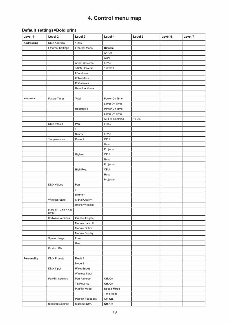
4. Control menu map
Default settings=Bold printLevel 1 Level 2 Level 3 Level 4 Level 5 Level 6 Level 7
Addressing DMX Address 1-255
Ethernet Settings Ethernet Mode Disable
ArtNet
ACN
Artnet Universe 0-255
sACN Universe 1-63999
IP Address
IP NetMask
IP Gateway
Default Address
Information Fixture Times Total Power On Time
Lamp On Time
Resettable Power On Time
Lamp On Time
Air Filt. Remains. 10-300
DMX Values Pan 0-255
:
Dimmer 0-255
Temperatures Current CPU
Head
Projector
Highest CPU
Head
Projector
High Res. CPU
Head
Projector
DMX Values Pan
:
Dimmer
Wireless State Signal Quality
Unlink Wireless
P o w e r C h a n n e l State
Software Versions Graphic Engine
Module Pan/Tilt
Module Optics
Module Display
Space Usage Free
Used
Product IDs
Personality DMX Presets Mode 1
Mode 2
DMX Input Wired Input
Wireless Input
Pan/Tilt Settings Pan Reverse Off, On
Tilt Reverse Off, On
Pan/Tilt Mode Speed Mode
Time Mode
Pan/Tilt Feedback Off, On,
Blackout Settings Blackout DMC Off, On
20
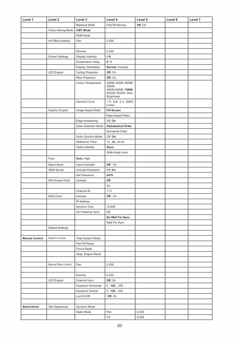
Level 1 Level 2 Level 3 Level 4 Level 5 Level 6 Level 7Blackout While Pan/Tilt Moving Off, On
Colour Mixing Mode CMY Mode
RGB Mode
Init Effect position Pan 0-255
:
Dimmer 0-255
Screen Settings Display Intensity 0-9
Screensaver Delay 0-10
Display Orientation Normal, Inverted
LED Engine Ceiling Projection Off, On,
Rear Projection Off, On,
Colour Temperature 3200K, 4200K, 5000K, 5500K,5600K,6500K, 7500K,8000K,9050K Max. Brightness
Gamma Curve 1.8, 2.2, 2.4, B&W, Linear
Gaphics Engine Image Aspect Ratio Fill Screen
Keep Aspect Ratio
Edge Antialiasing Off, On
Gobo Selection Mode Alphabetical Order
Numerical Order
Gobo Synchro Mode Off, On,
Slideshow Timer 1s...3s...30.0s
Optics Module None
Wide Angle Lens
Fans Auto, High
Stand Alone Input Overtake Off , On
WEB Server Activate Password Off, On
Set Password 2479
Wifi Access Point Activate Off
On
Channel ID 1-11
NAS Client Activate Off , On
IP Address
Synchro Time 10-600
On PowerUp Sync. Off
No Wait For Sync
Wait For Sync
Default Settings
Manual Control Reset Functions Total System Reset
Pan/Tilt Reset
Focus Reset
Grap. Engine Reset
Manual Effect Control Pan 0-255
:
Dimmer. 0-255
LED Engine External Input Off, On
Keystone Horizontal 0...128....255
Keystone Vertical 0...128....255
Led On/Off Off, On
Stand Alone Test Sequences Dynamic Mode
Static Mode Pan 0-255
Tilt 0-255
21
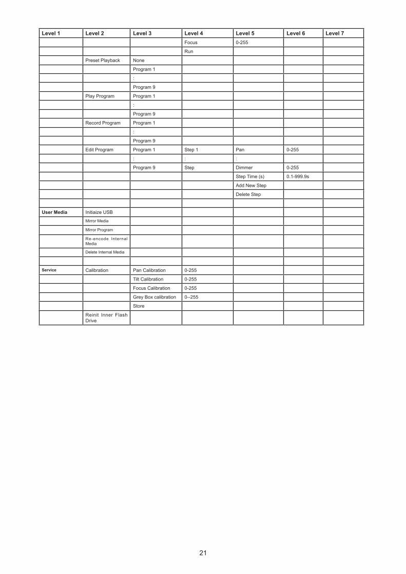
Level 1 Level 2 Level 3 Level 4 Level 5 Level 6 Level 7Focus 0-255
Run
Preset Playback None
Program 1
:
Program 9
Play Program Program 1
:
Program 9
Record Program Program 1
:
Program 9
Edit Program Program 1 Step 1 Pan 0-255
: : :
Program 9 Step Dimmer 0-255
Step Time (s) 0.1-999.9s
Add New Step
Delete Step
User Media Initiaize USB
Mirror Media
Mirror Program
Re-encode Internal Media
Delete Internal Media
Service Calibration Pan Calibration 0-255
Tilt Calibration 0-255
Focus Calibration 0-255
Grey Box calibration 0--255
Store
Reinit Inner Flash Drive
22
5. Control menu The Robin ProMotion is equipped with Robe Graphic Touch Screen (50x40mm / 1.97" x 1.57") which allows you to set the fixture´s behaviour according to your needs, obtain information on its operation and program it, if it has to be used in a stand-alone mode.
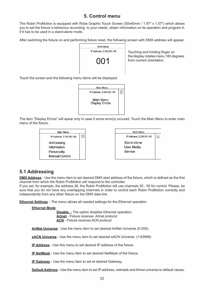
After switching the fixture on and performing fixture reset, the following screen with DMX address will appear.
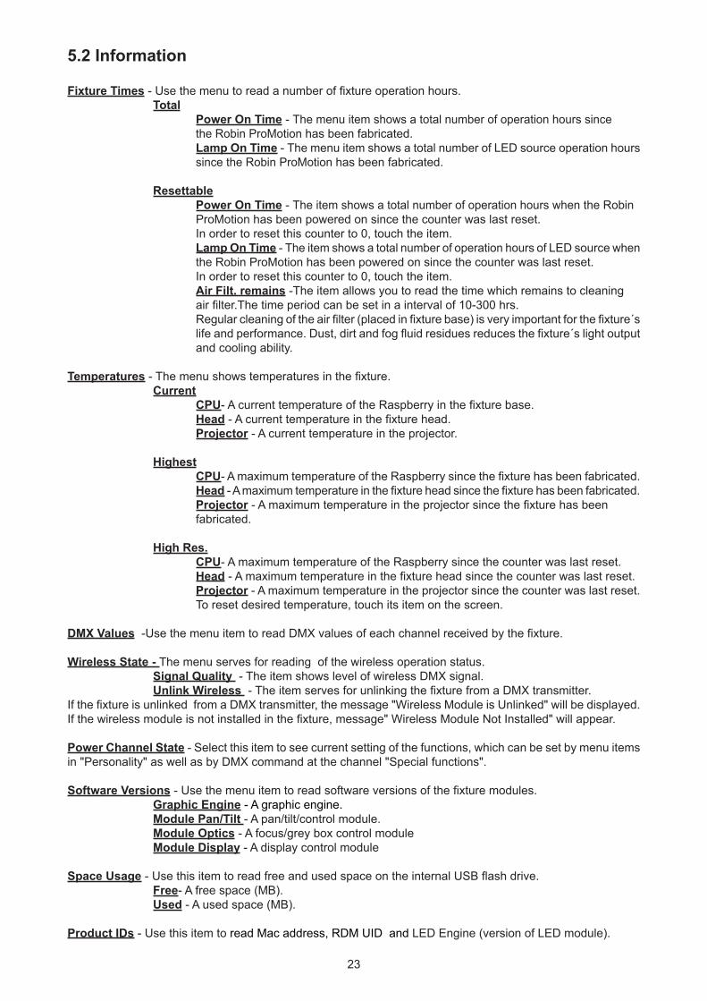
Touch the screen and the following menu items will be displayed.
The item "Display Errors" will apear only in case if some error(s) occured. Touch the Main Menu to enter main menu of the fixture.
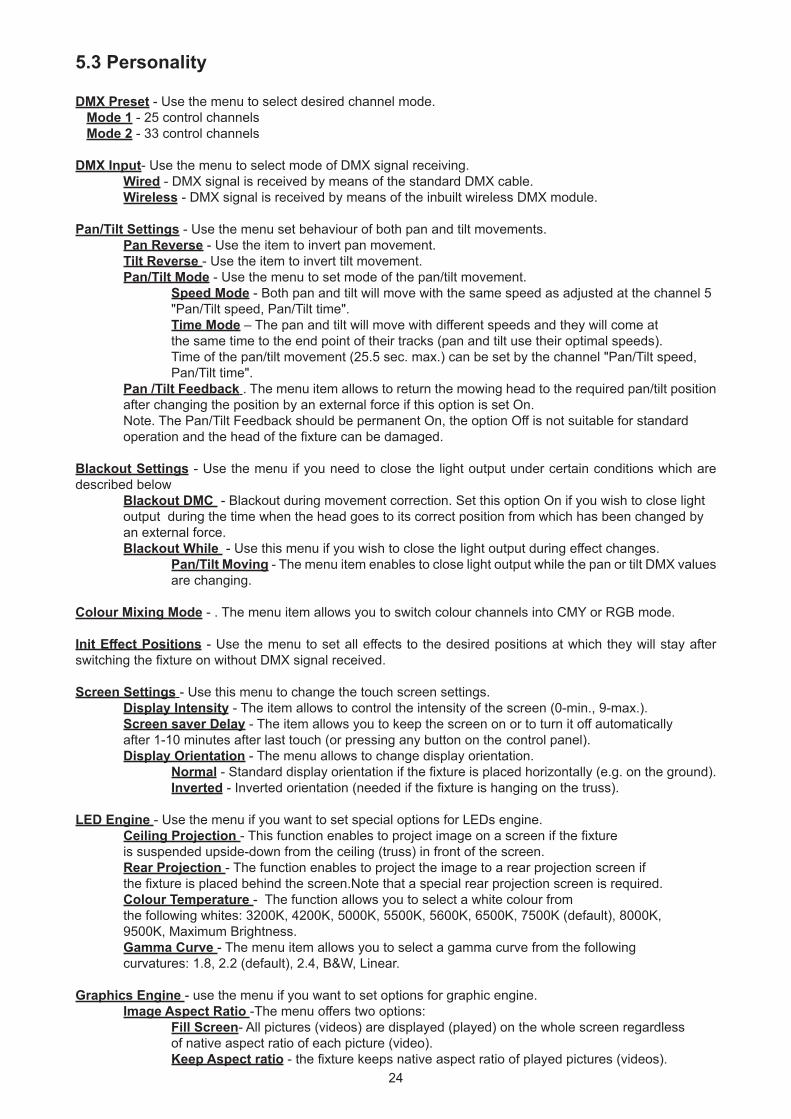
5.1 AddressingDMX Address - Use the menu item to set desired DMX start address of the fixture, which is defined as the first channel from which the Robin ProMotion will respond to the controller.If you set, for example, the address 26, the Robin ProMotion will use channels 26 - 50 for control. Please, be sure that you do not have any overlapping channels in order to control each Robin ProMotion correctly and independently from any other fixture on the DMX data link.
Ethernet Settings - The menu allows all needed settings for the Ethernet operation
Ethernet Mode Disable - The option disables Ethernet operation. Artnet - Fixture receives Artnet protocol ACN - Fixture receives ACN protocol
ArtNet Universe - Use the menu item to set desired ArtNet Universe (0-255).
sACN Universe - Use the menu item to set desired sACN Universe. (1-63999)
IP Address - Use this menu to set desired IP address of the fixture.
IP NetMask - Use the menu item to set desired NetMask of the fixture.
IP Gateway - Use the menu item to set et desired Gateway.
Default Address - Use the menu item to set IP address, netmask and Artnet universe to default values.
Touching and holding finger on the display rotates menu 180 degrees from current orientation.
23
5.2 Information
Fixture Times - Use the menu to read a number of fixture operation hours. Total Power On Time - The menu item shows a total number of operation hours since the Robin ProMotion has been fabricated. Lamp On Time - The menu item shows a total number of LED source operation hours since the Robin ProMotion has been fabricated.
Resettable Power On Time - The item shows a total number of operation hours when the Robin ProMotion has been powered on since the counter was last reset. In order to reset this counter to 0, touch the item. Lamp On Time - The item shows a total number of operation hours of LED source when the Robin ProMotion has been powered on since the counter was last reset. In order to reset this counter to 0, touch the item. Air Filt. remains -The item allows you to read the time which remains to cleaning air filter.The time period can be set in a interval of 10-300 hrs. Regular cleaning of the air filter (placed in fixture base) is very important for the fixture´s life and performance. Dust, dirt and fog fluid residues reduces the fixture´s light output and cooling ability.
Temperatures - The menu shows temperatures in the fixture. Current CPU- A current temperature of the Raspberry in the fixture base. Head - A current temperature in the fixture head. Projector - A current temperature in the projector.
Highest CPU- A maximum temperature of the Raspberry since the fixture has been fabricated. Head - A maximum temperature in the fixture head since the fixture has been fabricated. Projector - A maximum temperature in the projector since the fixture has been fabricated.
High Res. CPU- A maximum temperature of the Raspberry since the counter was last reset. Head - A maximum temperature in the fixture head since the counter was last reset. Projector - A maximum temperature in the projector since the counter was last reset. To reset desired temperature, touch its item on the screen.
DMX Values -Use the menu item to read DMX values of each channel received by the fixture.
Wireless State - The menu serves for reading of the wireless operation status. Signal Quality - The item shows level of wireless DMX signal. Unlink Wireless - The item serves for unlinking the fixture from a DMX transmitter.If the fixture is unlinked from a DMX transmitter, the message "Wireless Module is Unlinked" will be displayed.If the wireless module is not installed in the fixture, message" Wireless Module Not Installed" will appear.
Power Channel State - Select this item to see current setting of the functions, which can be set by menu items in "Personality" as well as by DMX command at the channel "Special functions".
Software Versions - Use the menu item to read software versions of the fixture modules. Graphic Engine - A graphic engine. Module Pan/Tilt - A pan/tilt/control module. Module Optics - A focus/grey box control module Module Display - A display control module
Space Usage - Use this item to read free and used space on the internal USB flash drive. Free- A free space (MB). Used - A used space (MB).
Product IDs - Use this item to read Mac address, RDM UID and LED Engine (version of LED module).
24
5.3 Personality
DMX Preset - Use the menu to select desired channel mode. Mode 1 - 25 control channels Mode 2 - 33 control channels
DMX Input- Use the menu to select mode of DMX signal receiving. Wired - DMX signal is received by means of the standard DMX cable. Wireless - DMX signal is received by means of the inbuilt wireless DMX module.
Pan/Tilt Settings - Use the menu set behaviour of both pan and tilt movements. Pan Reverse - Use the item to invert pan movement. Tilt Reverse - Use the item to invert tilt movement. Pan/Tilt Mode - Use the menu to set mode of the pan/tilt movement. Speed Mode - Both pan and tilt will move with the same speed as adjusted at the channel 5 "Pan/Tilt speed, Pan/Tilt time". Time Mode – The pan and tilt will move with different speeds and they will come at the same time to the end point of their tracks (pan and tilt use their optimal speeds). Time of the pan/tilt movement (25.5 sec. max.) can be set by the channel "Pan/Tilt speed, Pan/Tilt time". Pan /Tilt Feedback . The menu item allows to return the mowing head to the required pan/tilt position after changing the position by an external force if this option is set On. Note. The Pan/Tilt Feedback should be permanent On, the option Off is not suitable for standard operation and the head of the fixture can be damaged.
Blackout Settings - Use the menu if you need to close the light output under certain conditions which are described below Blackout DMC - Blackout during movement correction. Set this option On if you wish to close light output during the time when the head goes to its correct position from which has been changed by an external force. Blackout While - Use this menu if you wish to close the light output during effect changes. Pan/Tilt Moving - The menu item enables to close light output while the pan or tilt DMX values are changing.
Colour Mixing Mode - . The menu item allows you to switch colour channels into CMY or RGB mode.
Init Effect Positions - Use the menu to set all effects to the desired positions at which they will stay after switching the fixture on without DMX signal received.
Screen Settings - Use this menu to change the touch screen settings. Display Intensity - The item allows to control the intensity of the screen (0-min., 9-max.). Screen saver Delay - The item allows you to keep the screen on or to turn it off automatically after 1-10 minutes after last touch (or pressing any button on the control panel). Display Orientation - The menu allows to change display orientation. Normal - Standard display orientation if the fixture is placed horizontally (e.g. on the ground). Inverted - Inverted orientation (needed if the fixture is hanging on the truss).
LED Engine - Use the menu if you want to set special options for LEDs engine. Ceiling Projection - This function enables to project image on a screen if the fixture is suspended upside-down from the ceiling (truss) in front of the screen. Rear Projection - The function enables to project the image to a rear projection screen if the fixture is placed behind the screen.Note that a special rear projection screen is required. Colour Temperature - The function allows you to select a white colour from the following whites: 3200K, 4200K, 5000K, 5500K, 5600K, 6500K, 7500K (default), 8000K, 9500K, Maximum Brightness. Gamma Curve - The menu item allows you to select a gamma curve from the following curvatures: 1.8, 2.2 (default), 2.4, B&W, Linear.
Graphics Engine - use the menu if you want to set options for graphic engine. Image Aspect Ratio -The menu offers two options: Fill Screen- All pictures (videos) are displayed (played) on the whole screen regardless of native aspect ratio of each picture (video). Keep Aspect ratio - the fixture keeps native aspect ratio of played pictures (videos).
25
Edge Antialiasing -The function "smooths out" edges of the image during its rotation. Gobo Selection Mode - The menu allows you to select from two options of media files assigning to DMX values. Alphabetical Order- The media files assigned to DMX values are sorted in alphabetical order. Numerical Order- The media files assigned to DMX values are sorted in a numerical order. Default assigning is the alphabetical order. Gobo Synchro Mode -The function switches on/off algorithm for synchronic switching gobos. If you use only one fixture, the function should be off (gobo switching is faster). For two or more fixtures the function has to be on. Slide Show Timer -The option sets time period (0 - 30 sec.) during which a gobo stay in a position before changing during "Gobos presentation" function (channel 17/ Digital gobo wheel/ DMX range of 251-252). Optics Module -Select the option " Wide Angle Lens" if an additional wide angle lens is installed
Fans - Fan mode. Use the menu item to set the fixture fans to the auto-control mode ("Auto") or to the max. fans power ("High").
Stand Alone - The menu item allows you to customise playing of programs in the Stand Alone mode. Input Overtake -If the option is On and DMX signal from an external DMX controller has been received,the currently played program is interrupted and fixture behaves according to DMX signal.
WEB Server - The menu item allows you to set some item (s) regarding the WEB interface operation. Activate Password -If the option is On, the password is required at entering the WEB interface. Set Password -If the option is On, the passwor
Wifi Access Point - The menu allows you to witch On/Off access point . Activate Off - The menu item switches the Access point off On - The menu item switches Access point on. The option allows you a remote control of the fixture via a mobile phone or laptop. The name of Wi-Fi network is PromotionAP , password is promotion. Channel ID - The menu item allows you to select desired channel.
NAS Client - The menu item allows you to set a NAS client. Activate - The menu item "On" activated access to the NAS server (intended Promotion) and allows synchronization of NAS client with the NAS server. IP Address - The menu item allows you to set an IP address of the Promotion which serves as the NAS server. Synchro Time -The menu item allows you to set a time period (1 minute -600 minutes) after which media content of the NAS client will be synchronized with the NAS server. If the item is set at 0, no synchronization will run. On PowerUp Sync -The menu allows you to set a way of media content synchronization on the client fixture during its powering up. Off - The synchronization during fixture powering up is disabled. No Wait For Sync - The synchronization runs on background, the fixture will respond to a DMX controller during synchronization. Wait For Sync - The fixture waits for finishing of the synchronization and will not respond to the DMX controller until the synchronization is finished.
Note: During the media content synchronization, files from the internal USB flash drive of the NAS server are copied to the internal USB flash drive of the NAS client (new or changed files only).
Reset to Defaults - The menu item allows you to set all fixture parameters to the default (factory) values.
5.4 Manual Control
Reset Functions - This option allows you to reset function modules and effects and return them to their stand-ard values (positions). Total System Reset - The item resets all fixture modules. Pan/Tilt Reset - The item resets the pan/tilt module.
26
Focus Reset - The item resets the focus module. Grap, Engine Reset - The item resets the graphic engine module.
Manual Effect Control - The menu allows you to manually control each effect channel of the fixture.LED Engine - The menu allows you to set some parameters for the LED Engine. External Input - Via the menu option is possible to activate the external input (HDMI). Keystone Horizontal - The item allows you to use LED engine horizontal keystoning when the external input is active. Keystone Vertical - The item allows you to use LED engine vertical keystoning when the external input is active. Led On/Off - The item allows you to switch the LED engine off when the external input is active.
5.5 Stand- aloneTest Sequences -Use the menu to run a test/demo sequences without an external controller, which will show you some possibilities of using the fixture. Dynamic Mode - This mode uses all fixture functions including pan/tilt movement and therefore is suitable for a complete introduction of the fixture. Static Mode - This mode is suitable for projections on the wall, ceiling or ground without any pan/tilt movement. Adjust the pan, tilt, and focus to desired positions an start test sequences by touching the button Run.
Preset Playback - This menu allows you to select the program which will be played in a loop after switching the fixture on without connected DMX controller. None - The option disables “Preset playback” function. Program. 1- Program 9 - The options start user program 1-9. Selected program will be played continuously in a loop
Play Program - Select this menu to run one of 9 programs which have been created or recorded via the menu “Record Program”. Note: connected DMX signal pauses a program running, after disconnecting DMX signal the program continues is running.
Record Program - The menu allows you to record DMX data that receives the fixture and then replay them again via the menu “Play Program”. There is a list of 9 programs which can be used for recording DMX data.Touch desired program to start recording. To stop recording, touch the Stop Recording.Recorded programs can be copied to the USB memory stick (menu item "User Media") and after that loaded into another fixture.
Edit Program - the menu allows you to edit existing program or to create a new program.Each program can have up to 999 steps.After entering the menu "Edit Program", select desired program (1-9) and enter it . Select desired step and enter it.Now use menu items to set fixture channels to desired values.The item "Step Time" means a step time (0.1-999.9 seconds).The item " Add New Step" inserts a new step behind the current step. The item " Delete Step" deletes the current step. Note: DMX values are displayed at every channel only in the step 1. In the next steps (2, 3...) the channel value is displayed only in case, that this value was changed.
The icon serves for displaying a created step.
27
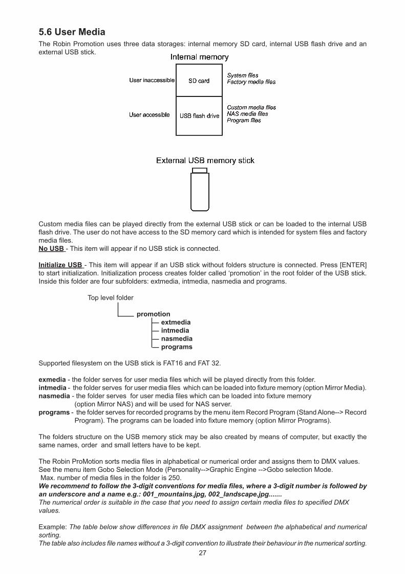
5.6 User MediaThe Robin Promotion uses three data storages: internal memory SD card, internal USB flash drive and an external USB stick.
Custom media files can be played directly from the external USB stick or can be loaded to the internal USB flash drive. The user do not have access to the SD memory card which is intended for system files and factory media files. No USB - This item will appear if no USB stick is connected.
Initialize USB - This item will appear if an USB stick without folders structure is connected. Press [ENTER] to start initialization. Initialization process creates folder called ‘promotion’ in the root folder of the USB stick. Inside this folder are four subfolders: extmedia, intmedia, nasmedia and programs.
Top level folder promotion extmedia intmedia nasmedia programs
Supported filesystem on the USB stick is FAT16 and FAT 32.
exmedia - the folder serves for user media files which will be played directly from this folder.intmedia - the folder serves for user media files which can be loaded into fixture memory (option Mirror Media). nasmedia - the folder serves for user media files which can be loaded into fixture memory (option Mirror NAS) and will be used for NAS server. programs - the folder serves for recorded programs by the menu item Record Program (Stand Alone--> Record Program). The programs can be loaded into fixture memory (option Mirror Programs).
The folders structure on the USB memory stick may be also created by means of computer, but exactly the same names, order and small letters have to be kept.
The Robin ProMotion sorts media files in alphabetical or numerical order and assigns them to DMX values.See the menu item Gobo Selection Mode (Personality-->Graphic Engine -->Gobo selection Mode. Max. number of media files in the folder is 250.We recommend to follow the 3-digit conventions for media files, where a 3-digit number is followed by an underscore and a name e.g.: 001_mountains.jpg, 002_landscape.jpg.......The numerical order is suitable in the case that you need to assign certain media files to specified DMXvalues.
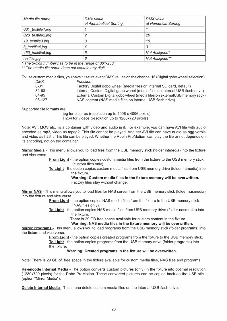
Example: The table below show differences in file DMX assignment between the alphabetical and numerical sorting.The table also includes file names without a 3-digit convention to illustrate their behaviour in the numerical sorting.
28
Media file name DMX valueat Alphabetical Sorting
DMX valueat Numerical Sorting
001_testfile1.jpg 1 1020_testfile2.jpg 2 2019_testfile3.jpg 3 193_testfile4.jpg 4 3460_testfile5.jpg 5 Not Assigned*testfile.jpg 6 Not Assigned**
* The 3-digit number has to be in the range of 001-250. ** The media file name does not contain any digit. To use custom media files, you have tu set relevant DMX values on the channel 16 (Digital gobo wheel selection). DMX Function 0-31 Factory Digital gobo wheel (media files on internal SD card, default) 32-63 Internal Custom Digital gobo wheel (media files on internal USB flash drive) 64-95 External Custom Digital gobo wheel (media files on externalUSB memory stick) 96-127 NAS content (NAS media files on internal USB flash drive)
Supported file formats are: jpg for pictures (resolution up to 4096 x 4096 pixels) H264 for videos (resolution up to 1280x720 pixels) Note: AVI, MOV etc. is a container with video and audio in it. For example, you can have AVI file with audio encoded as mp3, video as mpeg2. This file cannot be played. Another AVI file can have audio as ogg vorbis and video as h264. This file can be played. Whether the Robin ProMotion can play the file or not depends on its encoding, not on the container.
Mirror Media - This menu allows you to load files from the USB memory stick (folder intmedia) into the fixture and vice versa. From Light - the option copies custom media files from the fixture to the USB memory stick (custom files only). To Light - the option copies custom media files from USB memory drive (folder intmedia) into the fixture. Warning: Custom media files in the fixture memory will be overwritten. Factory files stay without change.
Mirror NAS - This menu allows you to load files for NAS server from the USB memory stick (folder nasmedia) into the fixture and vice versa. From Light - the option copies NAS media files from the fixture to the USB memory stick (NAS files only). To Light - the option copies NAS media files from USB memory drive (folder nasmedia) into the fixture. There is 29 GB free space available for custom content in the fixture. Warning: NAS media files in the fixture memory will be overwritten.Mirror Programs - This menu allows you to load programs from the USB memory stick (folder programs) into the fixture and vice versa. From Light - the option copies created programs from the fixture to the USB memory stick. To Light - the option copies programs from the USB memory drive (folder programs) into the fixture. Warning: Created programs in the fixture will be overwritten.
Note: There is 29 GB of free space in the fixture available for custom media files, NAS files and programs.
Re-encode Internal Media - The option converts custom pictures (only) in the fixture into optimal resolution (1280x720 pixels) for the Robe ProMotion. These converted pictures can be copied back on the USB stick (option "Mirror Media").
Delete Internal Media - This menu delete custom media files on the internal USB flash drive.
29
5.7 Service
Calibration - The menu allows you a fine adjustment of mechanical parts of the fixture: Pan Calibration - fine calibration of the pan position Tilt Calibration - fine calibration of the tilt position Focus Calibration - fine calibration of the focus position Grey Box Calibration - fine calibration of the grey box position Store - the option saves adjusted values into memory
Reinit Inner Flash Drive - The menu item formats internal USB flash drive. Warning: all user data will be deleted!
30
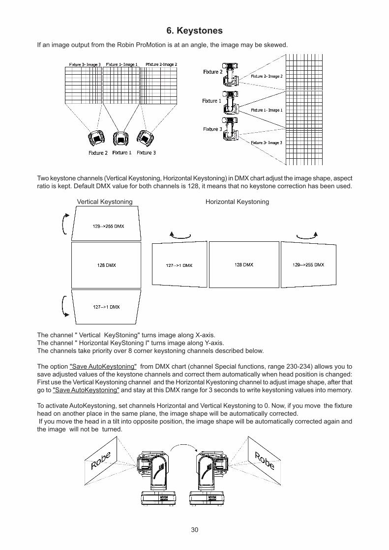
6. KeystonesIf an image output from the Robin ProMotion is at an angle, the image may be skewed.
Two keystone channels (Vertical Keystoning, Horizontal Keystoning) in DMX chart adjust the image shape, aspect ratio is kept. Default DMX value for both channels is 128, it means that no keystone correction has been used.
Vertical Keystoning Horizontal Keystoning
The channel " Vertical KeyStoning" turns image along X-axis.The channel " Horizontal KeyStoning l" turns image along Y-axis.The channels take priority over 8 corner keystoning channels described below.
The option "Save AutoKeystoning" from DMX chart (channel Special functions, range 230-234) allows you to save adjusted values of the keystone channels and correct them automatically when head position is changed:First use the Vertical Keystoning channel and the Horizontal Kyestoning channel to adjust image shape, after that go to "Save AutoKeystoning" and stay at this DMX range for 3 seconds to write keystoning values into memory.
To activate AutoKeystoning, set channels Horizontal and Vertical Keystoning to 0. Now, if you move the fixture head on another place in the same plane, the image shape will be automatically corrected. If you move the head in a tilt into opposite position, the image shape will be automatically corrected again and the image will not be turned.
31
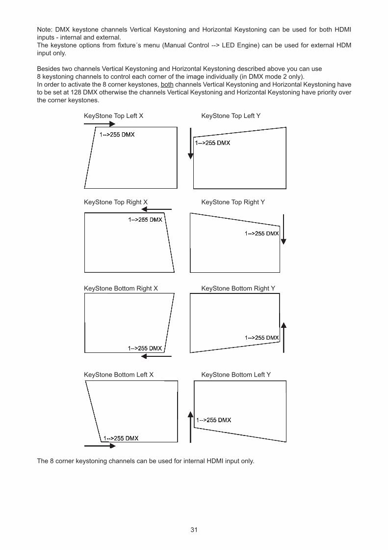
Note: DMX keystone channels Vertical Keystoning and Horizontal Keystoning can be used for both HDMI inputs - internal and external.The keystone options from fixture´s menu (Manual Control --> LED Engine) can be used for external HDM input only.
Besides two channels Vertical Keystoning and Horizontal Keystoning described above you can use 8 keystoning channels to control each corner of the image individually (in DMX mode 2 only). In order to activate the 8 corner keystones, both channels Vertical Keystoning and Horizontal Keystoning have to be set at 128 DMX otherwise the channels Vertical Keystoning and Horizontal Keystoning have priority over the corner keystones.
KeyStone Top Left X KeyStone Top Left Y
KeyStone Top Right X KeyStone Top Right Y
KeyStone Bottom Right X KeyStone Bottom Right Y
KeyStone Bottom Left X KeyStone Bottom Left Y
The 8 corner keystoning channels can be used for internal HDMI input only.
32
7. Using external HDMI inputIf you want to use the external HDMI input of the fixture, you have to activate the external HDMI input via setting DMX value into range of 220-229 on the channel 6 (Special functions). If you want to return back to the internal HDMI , set DMX value into range of 210-219 on this channel. Stay in desired DMX value for at least 3 seconds.
8. Ways of file transfer from/to the ProMotionYou can use several ways how to transfer custom media files to and from fixture.
1.USB stickTo copy custom files (NAS files, programs) into the fixture 1. Connect the ProMotion to the mains. 2. If you have a USB stick without created folders structure: A. Plug the USB stick into the fixture. B. Initialize the USB stick via menu "Initialize USB". 3. Plug the USB stick into computer. 4. Upload content into the folder intmedia (nasmedia for NAS files, programs for programs) and unplug the USB stick from computer. 5. Plug the USB stick back into the ProMotion. 6. Copy files into the ProMotion via the menu item "Mirror Media" ("Mirror NAS" for NAS files, Mirror Programs" for program files). 7. Unplug the USB stick from the ProMotion .
To copy custom files (NAS files, programs) from the fixture 1. Connect the ProMotion to the mains. 2. Plug the USB stick into the fixture. 3. Initialize the USB stick via menu "Initialize USB" (if you use USB stick without folders structure). 4. Copy files from the ProMotion via the menu item "Mirror Media" ("Mirror NAS" for NAS files, Mirror Programs" for program files) on the USB stick 5. Unplug the USB stick from the ProMotion.
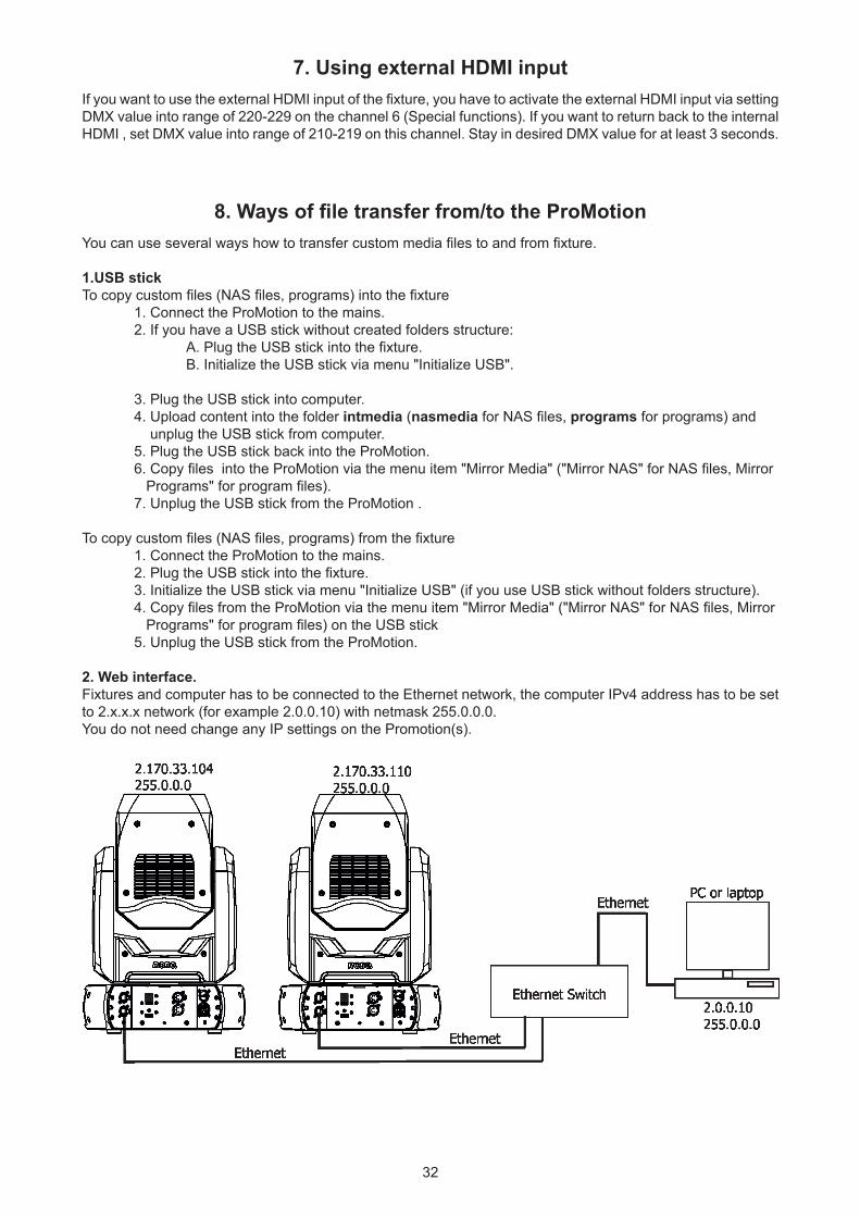
2. Web interface.Fixtures and computer has to be connected to the Ethernet network, the computer IPv4 address has to be set to 2.x.x.x network (for example 2.0.0.10) with netmask 255.0.0.0.You do not need change any IP settings on the Promotion(s).
33
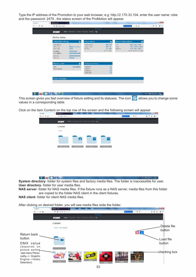
Type the IP address of the Promotion to your web browser, e.g. http://2.170.33.104, enter the user name: robe and the password: 2479 , the status screen of the ProMotion will appear.
This screen gives you fast overview of fixture setting and its statuses. The icon allows you to change some values in a corresponding table.
Click on the item Content on the top row of the screen and the following screen will appear
System directory- folder for system files and factory media files. The folder is inaccessible for user. User directory- folder for user media files.NAS server- folder for NAS media files. If the fixture runs as a NAS server, media files from this folder are copied to the folder NAS client in the client fixtures. NAS client- folder for client NAS media files.
After clicking on desired folder, you will see media files iside the folder.
checking box
Delete filebutton
Return backbutton Load file
buttonDMX va lue ( d e p e n d s o n picture sorting -see menu Perso-nality--> Graphic Engine-->Gobo Selection).
34
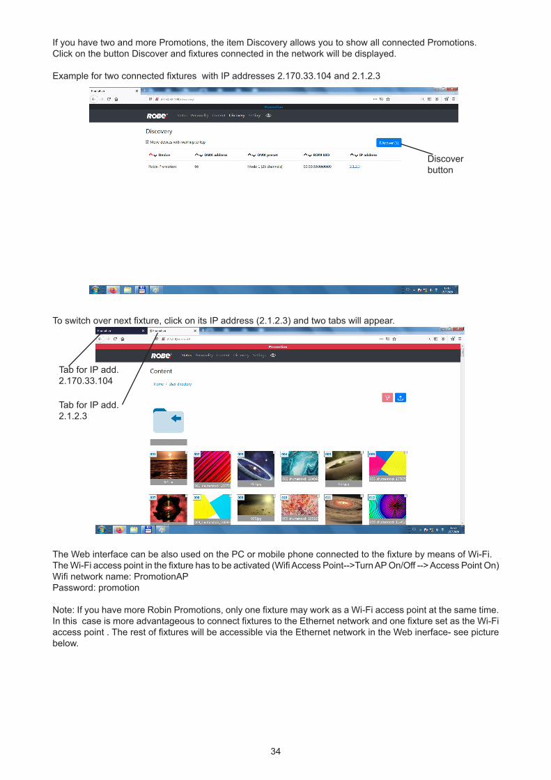
If you have two and more Promotions, the item Discovery allows you to show all connected Promotions.Click on the button Discover and fixtures connected in the network will be displayed.
Example for two connected fixtures with IP addresses 2.170.33.104 and 2.1.2.3
To switch over next fixture, click on its IP address (2.1.2.3) and two tabs will appear.
The Web interface can be also used on the PC or mobile phone connected to the fixture by means of Wi-Fi.The Wi-Fi access point in the fixture has to be activated (Wifi Access Point-->Turn AP On/Off --> Access Point On)Wifi network name: PromotionAPPassword: promotion
Note: If you have more Robin Promotions, only one fixture may work as a Wi-Fi access point at the same time. In this case is more advantageous to connect fixtures to the Ethernet network and one fixture set as the Wi-Fi access point . The rest of fixtures will be accessible via the Ethernet network in the Web inerface- see picture below.
Discover button
Tab for IP add. 2.170.33.104
Tab for IP add. 2.1.2.3
35
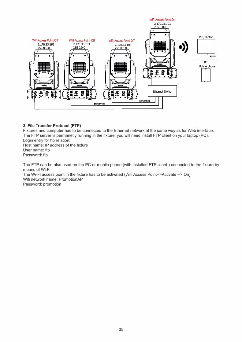
3. File Transfer Protocol (FTP)Fixtures and computer has to be connected to the Ethernet network at the same way as for Web interface. The FTP server is permanetly running in the fixture, you will need install FTP client on your laptop (PC). Login entry for ftp relation: Host name: IP address of the fixtureUser name: ftpPassword: ftp
The FTP can be also used on the PC or mobile phone (with installed FTP client ) connected to the fixture by means of Wi-Fi.The Wi-Fi access point in the fixture has to be activated (Wifi Access Point-->Activate --> On)Wifi network name: PromotionAPPassword: promotion
36
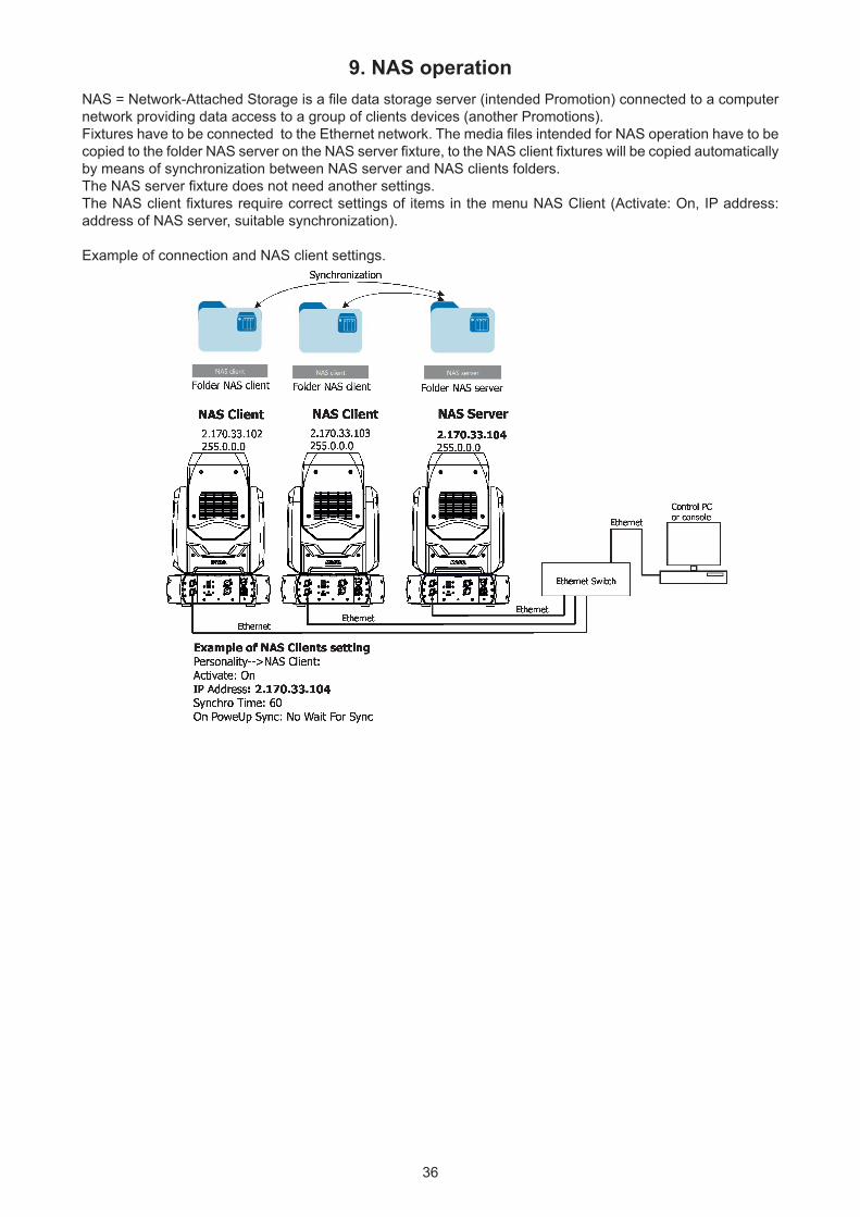
9. NAS operationNAS = Network-Attached Storage is a file data storage server (intended Promotion) connected to a computer network providing data access to a group of clients devices (another Promotions). Fixtures have to be connected to the Ethernet network. The media files intended for NAS operation have to be copied to the folder NAS server on the NAS server fixture, to the NAS client fixtures will be copied automatically by means of synchronization between NAS server and NAS clients folders.The NAS server fixture does not need another settings.The NAS client fixtures require correct settings of items in the menu NAS Client (Activate: On, IP address: address of NAS server, suitable synchronization).
Example of connection and NAS client settings.
37
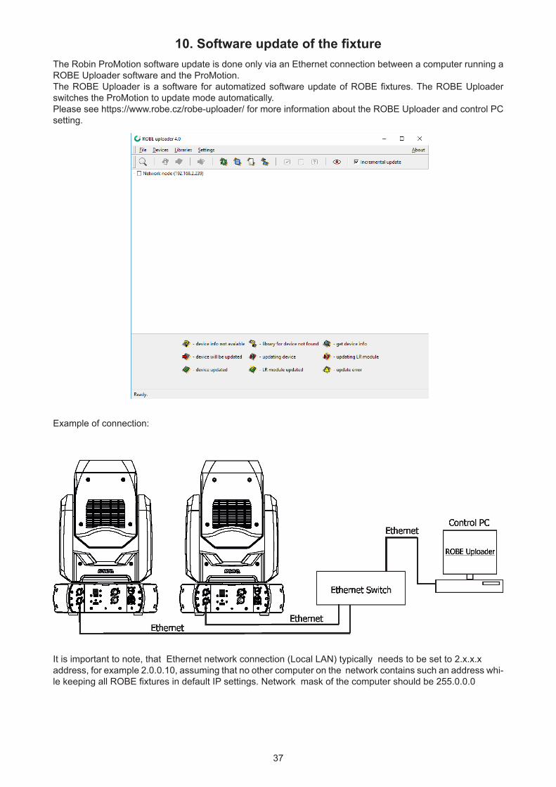
10. Software update of the fixtureThe Robin ProMotion software update is done only via an Ethernet connection between a computer running a ROBE Uploader software and the ProMotion. The ROBE Uploader is a software for automatized software update of ROBE fixtures. The ROBE Uploader switches the ProMotion to update mode automatically. Please see https://www.robe.cz/robe-uploader/ for more information about the ROBE Uploader and control PC setting.
Example of connection:
It is important to note, that Ethernet network connection (Local LAN) typically needs to be set to 2.x.x.x address, for example 2.0.0.10, assuming that no other computer on the network contains such an address whi-le keeping all ROBE fixtures in default IP settings. Network mask of the computer should be 255.0.0.0
38
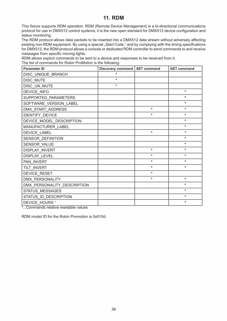
11. RDMThis fixture supports RDM operation. RDM (Remote Device Management) is a bi-directional communications protocol for use in DMX512 control systems, it is the new open standard for DMX512 device configuration and status monitoring.The RDM protocol allows data packets to be inserted into a DMX512 data stream without adversely affecting existing non-RDM equipment. By using a special „Start Code,“ and by complying with the timing specifications for DMX512, the RDM protocol allows a console or dedicated RDM controller to send commands to and receive messages from specific moving lights.RDM allows explicit commands to be sent to a device and responses to be received from it. The list of commands for Robin ProMotion is the following.Parameter ID Discovery command SET command GET commandDISC_UNIQUE_BRANCH *DISC_MUTE *DISC_UN_MUTE *DEVICE_INFO *SUPPORTED_PARAMETERS *SOFTWARE_VERSION_LABEL *DMX_START_ADDRESS * *IDENTIFY_DEVICE * *DEVICE_MODEL_DESCRIPTION *MANUFACTURER_LABEL *DEVICE_LABEL * *SENSOR_DEFINITION *SENSOR_VALUE *DISPLAY_INVERT * *DISPLAY_LEVEL * *PAN_INVERT * *TILT_INVERT * *DEVICE_RESET *DMX_PERSONALITY * *DMX_PERSONALITY_DESCRIPTION *STATUS_MESSAGES *STATUS_ID_DESCRIPTION *DEVICE_HOURS 1 *
1...Commands relative resetable values
RDM model ID for the Robin Promotion is 0x010d.
39
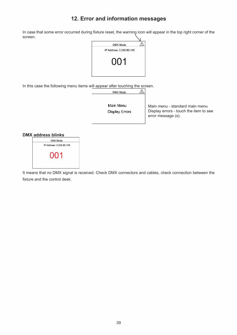
12. Error and information messages
In case that some error occurred during fixture reset, the warning icon will appear in the top right corner of the screen.
In this case the following menu items will appear after touching the screen.
DMX address blinks
It means that no DMX signal is received. Check DMX connectors and cables, check connection between the fixture and the control desk.
Main menu - standard main menuDisplay errors - touch the item to seeerror message (s).
40
13. Technical Specifications
Electrical Power supply:.........................electronic auto-ranging Input voltage range:............... 100-240V, 50-60Hz Fuse:.......................................T 2A/250V ~
Power consumption :...............140W
Mains input: CE - max. 16A cETLus - max. 10 A Mains output: CE - max. 15A cETLus - max. 9 A
Light engine Light source: RGB LED device Light output: 1000 ANSI lumens Light source lifetime: 20000 hours
Digital gobo/image/video projection output Aspect ratio: 16:9 Throw ratio: 3.5:1 Contrast ratio: 500:1 Display colours: 16.7 million colours Projector resolution: 1920 x 1080
Hardware Raspberry Pi Model 3B+ 1GB RAM
Operating system Linux
Graphic engine Digital gobo wheel with gobos, images and videos Gobo rotation and indexing Video speed control RGB or CMY colour mixing Virtual colour wheel with pre-programmed 234 colours including white Colour effect wheel with wide range of built-in colour effects (colour transitions and cross-fades, multiple colour images, rainbow effects) Effect wheel with wide range of graphic effects Effect speed control Horizontal/Vertical keystoning Smooth dimmer Shutter and strobe effects Video bitrate used in original content: 2000-12000 kbit/s (video codec H264, 25fps, resolution 1024x576) Supported Image Format: JPG (up to 4096 x 4096 pixels), non progressive/non interpolated Supported Video Format: H264 Recommended refresh rate: 1280x720@30Hz* * for video files saved on the internal USB flash drive and the external USB memory stick.
Free space available for custom content 29 GB
Focus Motorized focus
41
Gray box correction Gray box correction from max. diameter to min. diameter of the light beamStrobe Independent strobe effect with variable speed (0.3 - 20Hz) Random strobe effectDimmer Smooth dimmer from 0 - 100 %
Pan/Tilt Max. pan movement range: 540° Max. tilt movement range: 260° 16 bit movement resolution Automatic Pan/Tilt position correction Remotely controllable speed of pan/tilt movement for easy programmingControl Upload and projection of custom artwork, photographs and videos Live input via external HDMI Setting & Addressing: two-row LCD display & 4 control buttons Protocols: USITT DMX-512-A, RDM, ArtNet Optional wireless external module available: CRMX™ technology from Lumen Radio DMX modes: 2 (25 and 33 control channels) Ethernet port: Art-Net, ready for ACN Recommended and supported filesystem on USB memory devices: FAT16, FAT 32
External Wireless DMX/RDM module (optional) Compliance with USITT DMX-512 (1986 & 1990) and 512-A Full DMX fidelity and frame integrity Auto sensing of DMX frame rate and frame size <5ms DMX latency Operational frequency range of 2402-2480 MHz Producer: LumenRadio
Connection DMX IN/OUT: Locking 5-pin XLR 2 x USB 2.0 connector (series A) ArtNet IN/OUT: RJ 45 (Neutrik Ethercon) External video input: 1 x HDMI AC power IN/Out: Chassis connector Neutrik PowerCon TRUE 1, NAC3PX-TOP
Max. number of fixtures in Ethernet IN/Out line 8
Rigging Mounting points: one pair of 1/4-turn locks Mounting horizontally or vertically via Omega holder
Temperatures Ambient operating temperature : 0 - 40° C Maximum housing temperature : 60° C
Distances Min. distance from flammable surfaces: 0.5 m Min. distance to projection surface: 0.8 m
Total heat dissipation 360 BTU/h (calculated)
42
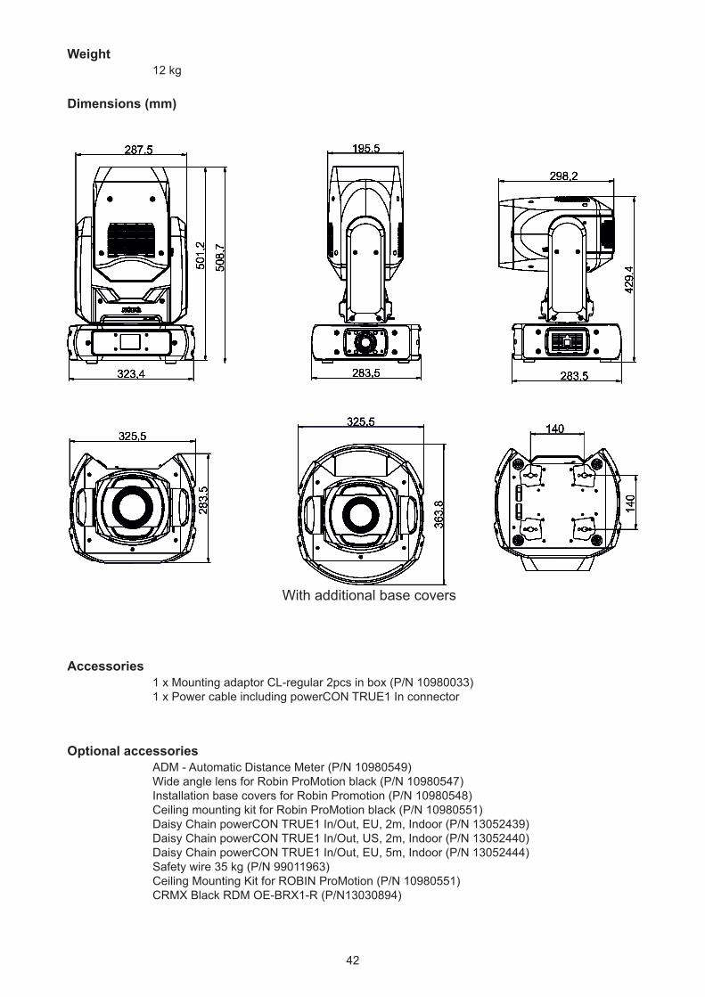
Weight 12 kg
Dimensions (mm)
Accessories 1 x Mounting adaptor CL-regular 2pcs in box (P/N 10980033) 1 x Power cable including powerCON TRUE1 In connector
Optional accessories ADM - Automatic Distance Meter (P/N 10980549) Wide angle lens for Robin ProMotion black (P/N 10980547) Installation base covers for Robin Promotion (P/N 10980548) Ceiling mounting kit for Robin ProMotion black (P/N 10980551) Daisy Chain powerCON TRUE1 In/Out, EU, 2m, Indoor (P/N 13052439) Daisy Chain powerCON TRUE1 In/Out, US, 2m, Indoor (P/N 13052440) Daisy Chain powerCON TRUE1 In/Out, EU, 5m, Indoor (P/N 13052444) Safety wire 35 kg (P/N 99011963) Ceiling Mounting Kit for ROBIN ProMotion (P/N 10980551) CRMX Black RDM OE-BRX1-R (P/N13030894)
With additional base covers
43
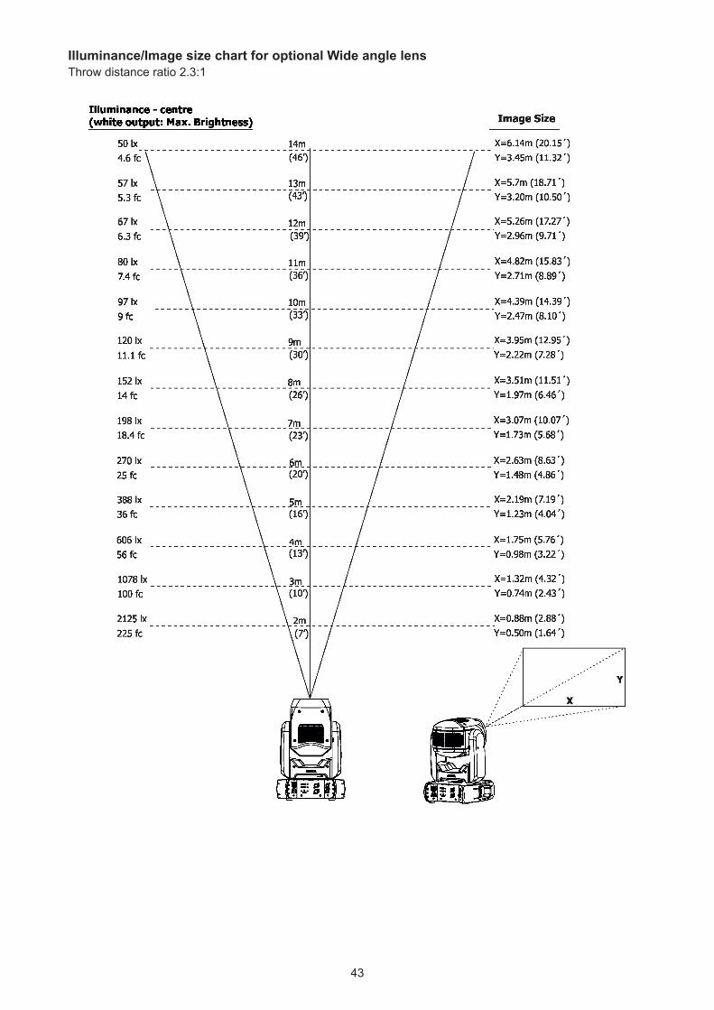
Illuminance/Image size chart for optional Wide angle lens Throw distance ratio 2.3:1
44
14. Maintenance and cleaning
DANGER !Disconnect from the mains before starting any
maintenance work
Important! Never use alcohols (ethanol, methanol, isopropyl alcohol), acetone and another aggressive solvents for cleaning the optical parts of the fixture.
It is absolutely essential that the fixture is kept clean and that dust, dirt and smoke-fluid residues must not build up on or within the fixture. Otherwise, the fixture‘s light-output will be significantly reduced. Regular cleaning will not only ensure the maximum light-output, but will also allow the fixture to function reliably throughout its life. Use low-pressure compressed air to remove coarse dust from optical components.Use distilled water with weak detergent solution and lint-free small cloth for further cleaning of front glass.The cooling fans should be cleaned according to the situation (at least annually).The interior of the base should be cleaned at least annually using a vacuum-cleaner or an air-jet.
More complicated maintenance and service operations are only to be carried out by authorized distributors.
Important! Check the air filters periodically and clean before it become clogged!
Clean air filters placed in both covers of the head and one in the fixture base. The filters in head covers are fastened by means of velcro fastener and the filter in the base is placed under a grille, which is fastened by means of two magnets. Use a vacuum cleaner, compressed air or you can wash them and put back dry.After replacing the air filters, set the remaining time counter in the menu "Fixture Information" (Fixture Informa-tion--->Fixture Times--->Resettable Times--->Air Filt. Remains).
45
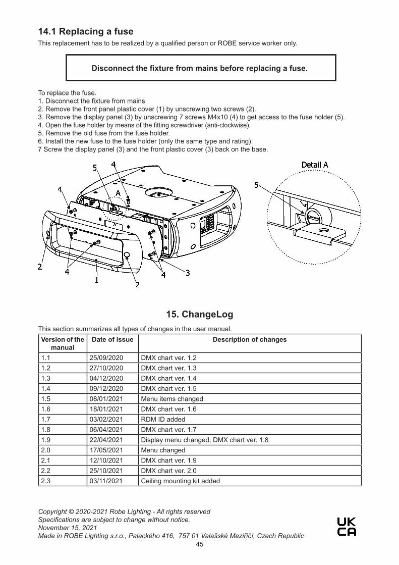
14.1 Replacing a fuseThis replacement has to be realized by a qualified person or ROBE service worker only.
Disconnect the fixture from mains before replacing a fuse.
To replace the fuse.1. Disconnect the fixture from mains2. Remove the front panel plastic cover (1) by unscrewing two screws (2).3. Remove the display panel (3) by unscrewing 7 screws M4x10 (4) to get access to the fuse holder (5).4. Open the fuse holder by means of the fitting screwdriver (anti-clockwise).5. Remove the old fuse from the fuse holder.6. Install the new fuse to the fuse holder (only the same type and rating).7 Screw the display panel (3) and the front plastic cover (3) back on the base.
15. ChangeLog This section summarizes all types of changes in the user manual.Version of the
manualDate of issue Description of changes
1.1 25/09/2020 DMX chart ver. 1.21.2 27/10/2020 DMX chart ver. 1.31.3 04/12/2020 DMX chart ver. 1.41.4 09/12/2020 DMX chart ver. 1.51.5 08/01/2021 Menu items changed1.6 18/01/2021 DMX chart ver. 1.61.7 03/02/2021 RDM ID added1.8 06/04/2021 DMX chart ver. 1.71.9 22/04/2021 Display menu changed, DMX chart ver. 1.82.0 17/05/2021 Menu changed2.1 12/10/2021 DMX chart ver. 1.92.2 25/10/2021 DMX chart ver. 2.02.3 03/11/2021 Ceiling mounting kit added
Copyright © 2020-2021 Robe Lighting - All rights reservedSpecifications are subject to change without notice.November 15, 2021Made in ROBE Lighting s.r.o., Palackého 416, 757 01 Valašské Meziříčí, Czech Republic
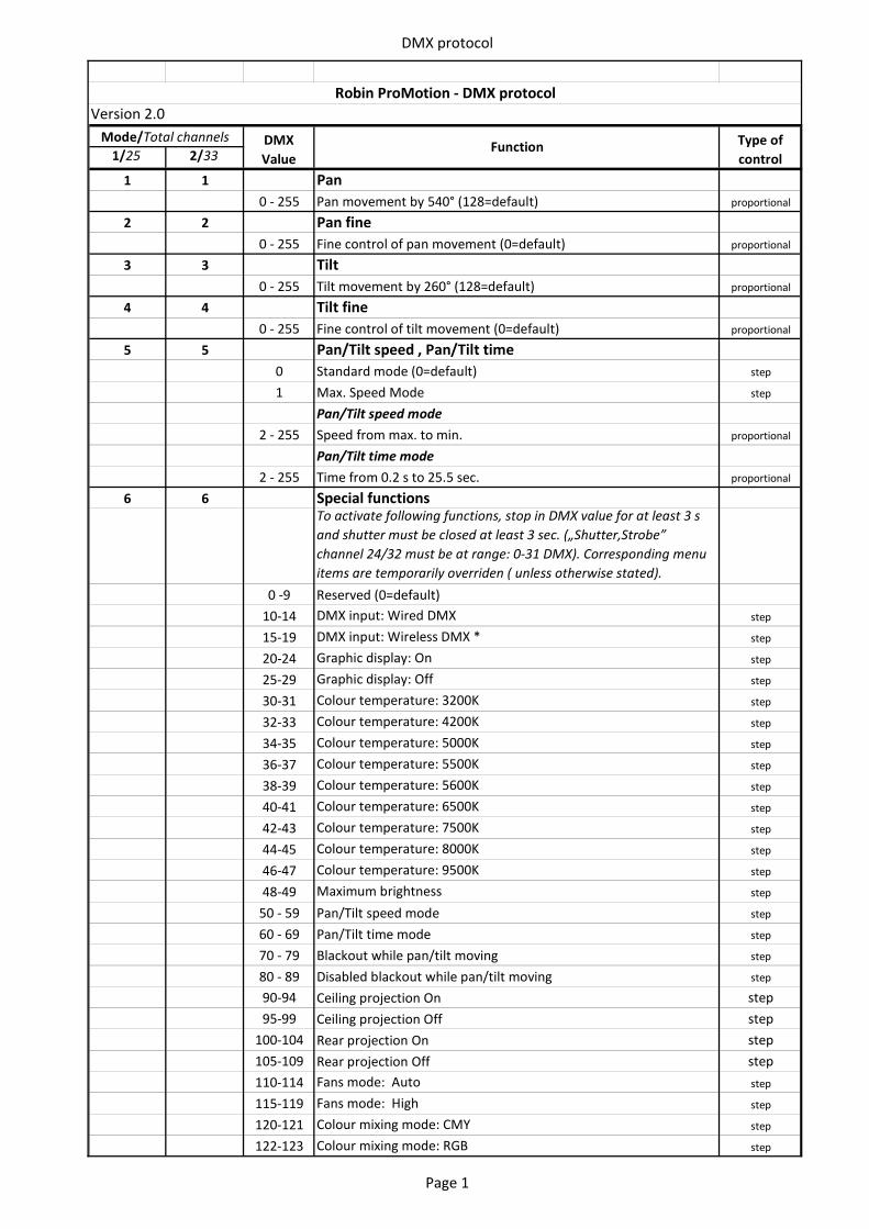
DMX protocol
1/25 2/33
1 1 Pan0 - 255 Pan movement by 540° (128=default) proportional
2 2 Pan fine0 - 255 Fine control of pan movement (0=default) proportional
3 3 Tilt0 - 255 Tilt movement by 260° (128=default) proportional
4 4 Tilt fine0 - 255 Fine control of tilt movement (0=default) proportional
5 5 Pan/Tilt speed , Pan/Tilt time0 Standard mode (0=default) step
1 Max. Speed Mode step
Pan/Tilt speed mode2 - 255 Speed from max. to min. proportional
Pan/Tilt time mode 2 - 255 Time from 0.2 s to 25.5 sec. proportional
6 6 Special functionsTo activate following functions, stop in DMX value for at least 3 s and shutter must be closed at least 3 sec. („Shutter,Strobe” channel 24/32 must be at range: 0-31 DMX). Corresponding menu items are temporarily overriden ( unless otherwise stated).
0 -9 Reserved (0=default)10-14 DMX input: Wired DMX step
15-19 DMX input: Wireless DMX * step
20-24 Graphic display: On step
25-29 Graphic display: Off step
30-31 Colour temperature: 3200K step
32-33 Colour temperature: 4200K step
34-35 Colour temperature: 5000K step
36-37 Colour temperature: 5500K step
38-39 Colour temperature: 5600K step
40-41 Colour temperature: 6500K step
42-43 Colour temperature: 7500K step
44-45 Colour temperature: 8000K step
46-47 Colour temperature: 9500K step
48-49 Maximum brightness step
50 - 59 Pan/Tilt speed mode step
60 - 69 Pan/Tilt time mode step
70 - 79 Blackout while pan/tilt moving step
80 - 89 Disabled blackout while pan/tilt moving step
90-94 Ceiling projection On step95-99 Ceiling projection Off step
100-104 Rear projection On step105-109 Rear projection Off step110-114 Fans mode: Auto step
115-119 Fans mode: High step
120-121 Colour mixing mode: CMY step
122-123 Colour mixing mode: RGB step
Robin ProMotion - DMX protocolVersion 2.0
DMX Value
Function Type of control
Mode/Total channels
Page 1
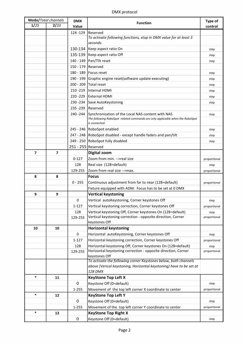
DMX protocol
1/25 2/33DMX Value
Function Type of control
Mode/Total channels
124 -129 ReservedTo activate following functions, stop in DMX value for at least 3 seconds.
130-134 Keep aspect ratio On step
135-139 Keep aspect ratio Off step
140 - 149 Pan/Tilt reset step
150 - 179 Reserved180 - 189 Focus reset step
190 - 199 Graphic engine reset(software update executing) step
200 - 209 Total reset step
210 -219 Internal HDMI step
220 -229 External HDMI step
230 -234 Save AutoKeystoning step
235 -239 Reserved240 -244 Synchronization of the Local NAS content with NAS step
The following RoboSpot related commands are only applicable when the RoboSpot is connected:
245 - 246 RoboSpot enabled step
247 - 248 RoboSpot disabled - except handle faders and pan/tilt step
249 - 250 RoboSpot fully disabled step
251 - 255 Reserved7 7 Digital zoom
0-127 Zoom from min. -->real size proportional
128 Real size (128=default) step
129-255 Zoom from real size -->max. proportional
8 8 Focus0 - 255 Continuous adjustment from far to near (128=default) proportional
Fixture equipped with ADM: Focus has to be set at 0 DMX 9 9 Vertical keystoning
0 Vertical autoKeystoning, Corner keystones Off step
1-127 Vertical keystoning correction, Corner keystones Off proportional
128 Vertical keystoning Off, Corner keystones On (128=default) step
129-255 Vertical keystoning correction - oppozite direction, Corner keystones Off
proportional
10 10 Horizontal keystoning 0 Horizontal autoKeystoning, Corner keystones Off step
1-127 Horizontal keystoning correction, Corner keystones Off proportional
128 Horizontal keystoning Off, Corner keystones On (128=default) step
129-255 Horizontal keystoning correction - oppozite direction, Corner keystones Off
proportional
To activate the following corner Keystones below, both channels above (Verical keystoning, Horizontal keystoning) have to be set at 128 DMX
* 11 KeyStone Top Left X0 Keystone Off (0=default) step
1-255 Movement of the top left corner X coordinate to center proportional
* 12 KeyStone Top Left Y0 Keystone Off (0=default) step
1-255 Movement of the top left corner Y coordinate to center proportional
* 13 KeyStone Top Right X0 Keystone Off (0=default) step
Page 2
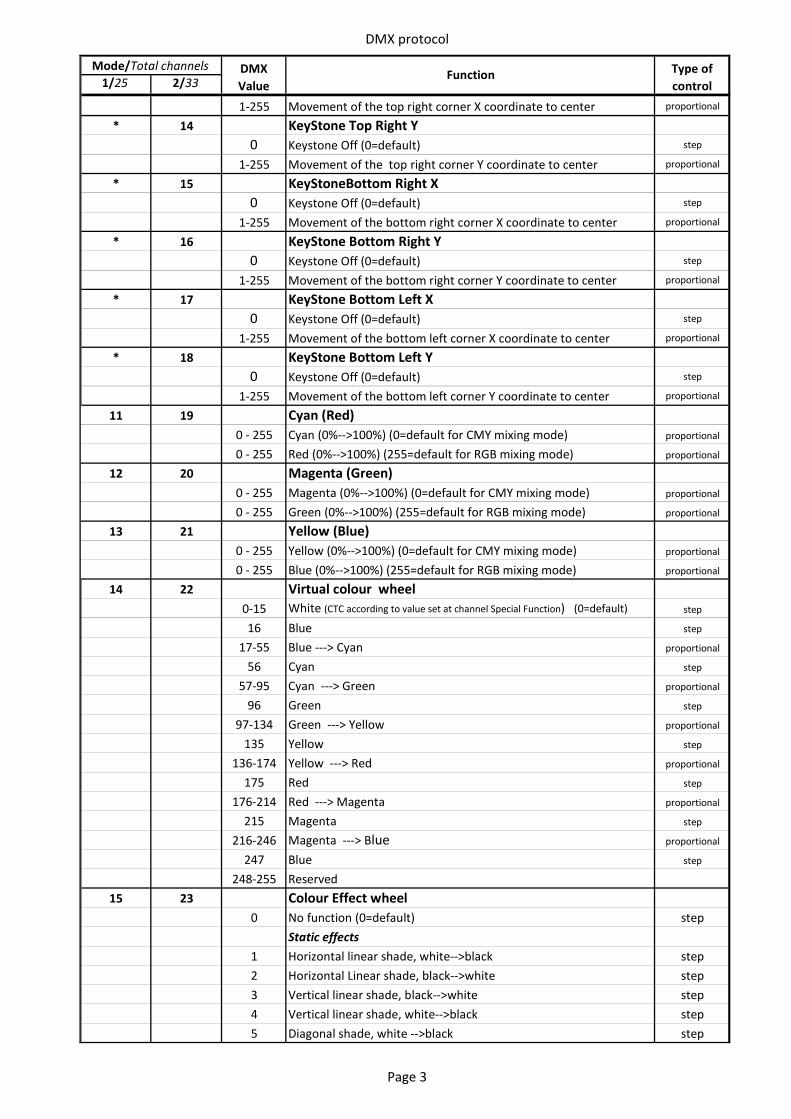
DMX protocol
1/25 2/33DMX Value
Function Type of control
Mode/Total channels
1-255 Movement of the top right corner X coordinate to center proportional
* 14 KeyStone Top Right Y0 Keystone Off (0=default) step
1-255 Movement of the top right corner Y coordinate to center proportional
* 15 KeyStoneBottom Right X0 Keystone Off (0=default) step
1-255 Movement of the bottom right corner X coordinate to center proportional
* 16 KeyStone Bottom Right Y0 Keystone Off (0=default) step
1-255 Movement of the bottom right corner Y coordinate to center proportional
* 17 KeyStone Bottom Left X0 Keystone Off (0=default) step
1-255 Movement of the bottom left corner X coordinate to center proportional
* 18 KeyStone Bottom Left Y0 Keystone Off (0=default) step
1-255 Movement of the bottom left corner Y coordinate to center proportional
11 19 Cyan (Red)0 - 255 Cyan (0%-->100%) (0=default for CMY mixing mode) proportional
0 - 255 Red (0%-->100%) (255=default for RGB mixing mode) proportional
12 20 Magenta (Green)0 - 255 Magenta (0%-->100%) (0=default for CMY mixing mode) proportional
0 - 255 Green (0%-->100%) (255=default for RGB mixing mode) proportional
13 21 Yellow (Blue)0 - 255 Yellow (0%-->100%) (0=default for CMY mixing mode) proportional
0 - 255 Blue (0%-->100%) (255=default for RGB mixing mode) proportional
14 22 Virtual colour wheel 0-15 White (CTC according to value set at channel Special Function) (0=default) step
16 Blue step
17-55 Blue ---> Cyan proportional
56 Cyan step
57-95 Cyan ---> Green proportional
96 Green step
97-134 Green ---> Yellow proportional
135 Yellow step
136-174 Yellow ---> Red proportional
175 Red step
176-214 Red ---> Magenta proportional
215 Magenta step
216-246 Magenta ---> Blue proportional
247 Blue step
248-255 Reserved15 23 Colour Effect wheel
0 No function (0=default) stepStatic effects
1 Horizontal linear shade, white-->black step2 Horizontal Linear shade, black-->white step3 Vertical linear shade, black-->white step4 Vertical linear shade, white-->black step5 Diagonal shade, white -->black step
Page 3
DMX protocol
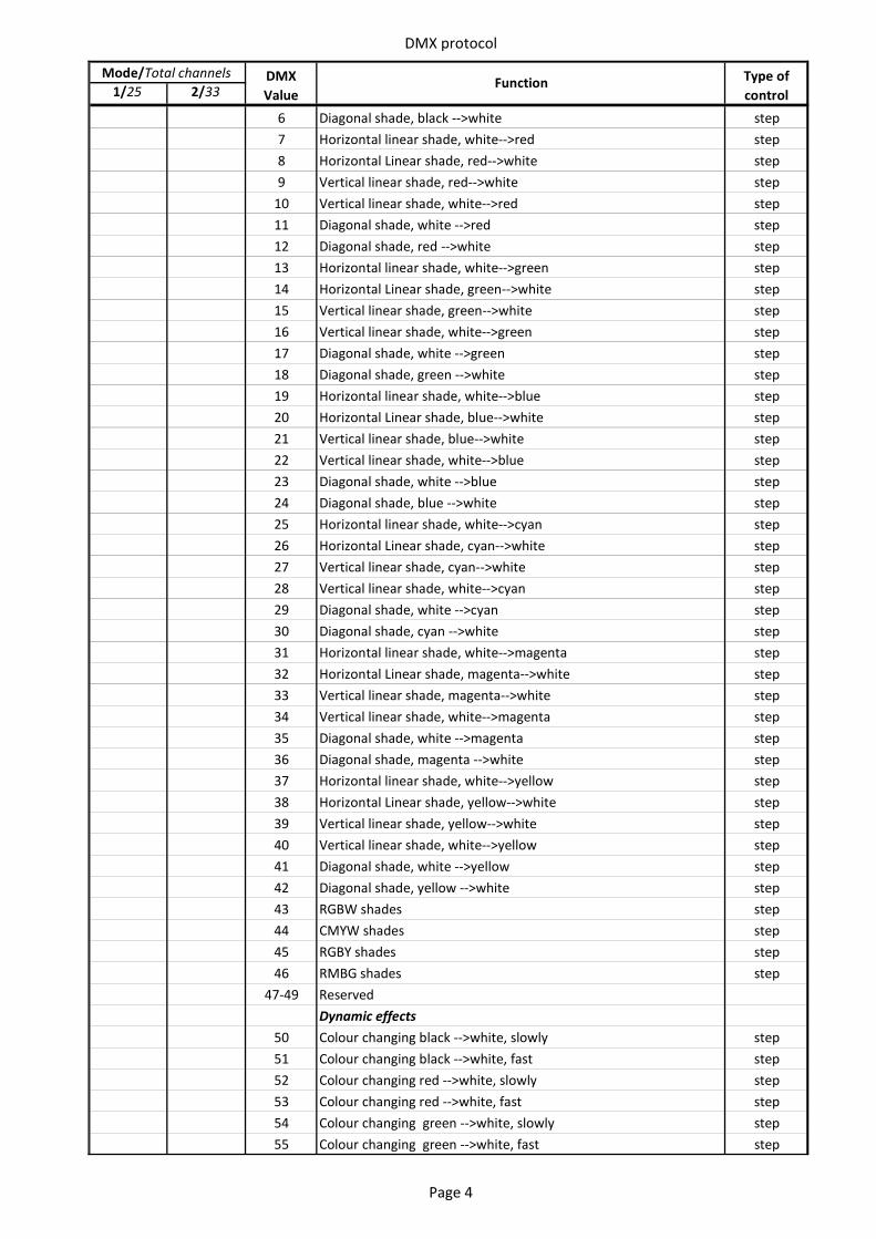
1/25 2/33DMX Value
Function Type of control
Mode/Total channels
6 Diagonal shade, black -->white step7 Horizontal linear shade, white-->red step8 Horizontal Linear shade, red-->white step9 Vertical linear shade, red-->white step
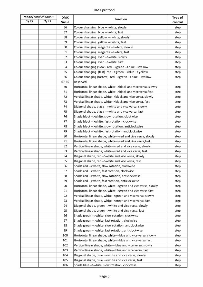
10 Vertical linear shade, white-->red step11 Diagonal shade, white -->red step12 Diagonal shade, red -->white step13 Horizontal linear shade, white-->green step14 Horizontal Linear shade, green-->white step15 Vertical linear shade, green-->white step16 Vertical linear shade, white-->green step17 Diagonal shade, white -->green step18 Diagonal shade, green -->white step19 Horizontal linear shade, white-->blue step20 Horizontal Linear shade, blue-->white step21 Vertical linear shade, blue-->white step22 Vertical linear shade, white-->blue step23 Diagonal shade, white -->blue step24 Diagonal shade, blue -->white step25 Horizontal linear shade, white-->cyan step26 Horizontal Linear shade, cyan-->white step27 Vertical linear shade, cyan-->white step28 Vertical linear shade, white-->cyan step29 Diagonal shade, white -->cyan step30 Diagonal shade, cyan -->white step31 Horizontal linear shade, white-->magenta step32 Horizontal Linear shade, magenta-->white step33 Vertical linear shade, magenta-->white step34 Vertical linear shade, white-->magenta step35 Diagonal shade, white -->magenta step36 Diagonal shade, magenta -->white step37 Horizontal linear shade, white-->yellow step38 Horizontal Linear shade, yellow-->white step39 Vertical linear shade, yellow-->white step40 Vertical linear shade, white-->yellow step41 Diagonal shade, white -->yellow step42 Diagonal shade, yellow -->white step43 RGBW shades step44 CMYW shades step45 RGBY shades step46 RMBG shades step
47-49 ReservedDynamic effects
50 Colour changing black -->white, slowly step51 Colour changing black -->white, fast step52 Colour changing red -->white, slowly step53 Colour changing red -->white, fast step54 Colour changing green -->white, slowly step55 Colour changing green -->white, fast step
Page 4
DMX protocol
1/25 2/33DMX Value
Function Type of control
Mode/Total channels
56 Colour changing blue -->white, slowly step57 Colour changing blue -->white, fast step58 Colour changing yellow -->white, slowly step59 Colour changing yellow -->white, fast step60 Colour changing magenta -->white, slowly step61 Colour changing magenta -->white, fast step62 Colour changing cyan -->white, slowly step63 Colour changing cyan -->white, fast step64 Colour changing (slow) red -->green -->blue -->yellow step65 Colour changing (fast) red -->green -->blue -->yellow step66 Colour changing (fastest) red -->green -->blue -->yellow step
67-69 Reserved70 Horizontal linear shade, white-->black and vice versa, slowly step71 Horizontal linear shade, white-->black and vice versa,fast step72 Vertical linear shade, white-->black and vice versa, slowly step73 Vertical linear shade, white-->black and vice versa, fast step74 Diagonal shade, black -->white and vice versa, slowly step75 Diagonal shade, black -->white and vice versa, fast step76 Shade black -->white, slow rotation, clockwise step77 Shade black -->white, fast rotation, clockwise step78 Shade black -->white, slow rotation, anticlockwise step79 Shade black -->white, fast rotation, anticlockwise step80 Horizontal linear shade, white-->red and vice versa, slowly step81 Horizontal linear shade, white-->red and vice versa,fast step82 Vertical linear shade, white-->red and vice versa, slowly step83 Vertical linear shade, white-->red and vice versa, fast step84 Diagonal shade, red -->white and vice versa, slowly step85 Diagonal shade, red -->white and vice versa, fast step86 Shade red -->white, slow rotation, clockwise step87 Shade red -->white, fast rotation, clockwise step88 Shade red -->white, slow rotation, anticlockwise step89 Shade red -->white, fast rotation, anticlockwise step90 Horizontal linear shade, white-->green and vice versa, slowly step91 Horizontal linear shade, white-->green and vice versa,fast step92 Vertical linear shade, white-->green and vice versa, slowly step93 Vertical linear shade, white-->green and vice versa, fast step94 Diagonal shade, green -->white and vice versa, slowly step95 Diagonal shade, green -->white and vice versa, fast step96 Shade green -->white, slow rotation, clockwise step97 Shade green -->white, fast rotation, clockwise step98 Shade green -->white, slow rotation, anticlockwise step99 Shade green -->white, fast rotation, anticlockwise step
100 Horizontal linear shade, white-->blue and vice versa, slowly step101 Horizontal linear shade, white-->blue and vice versa,fast step102 Vertical linear shade, white-->blue and vice versa, slowly step103 Vertical linear shade, white-->blue and vice versa, fast step104 Diagonal shade, blue -->white and vice versa, slowly step105 Diagonal shade, blue -->white and vice versa, fast step106 Shade blue -->white, slow rotation, clockwise step
Page 5
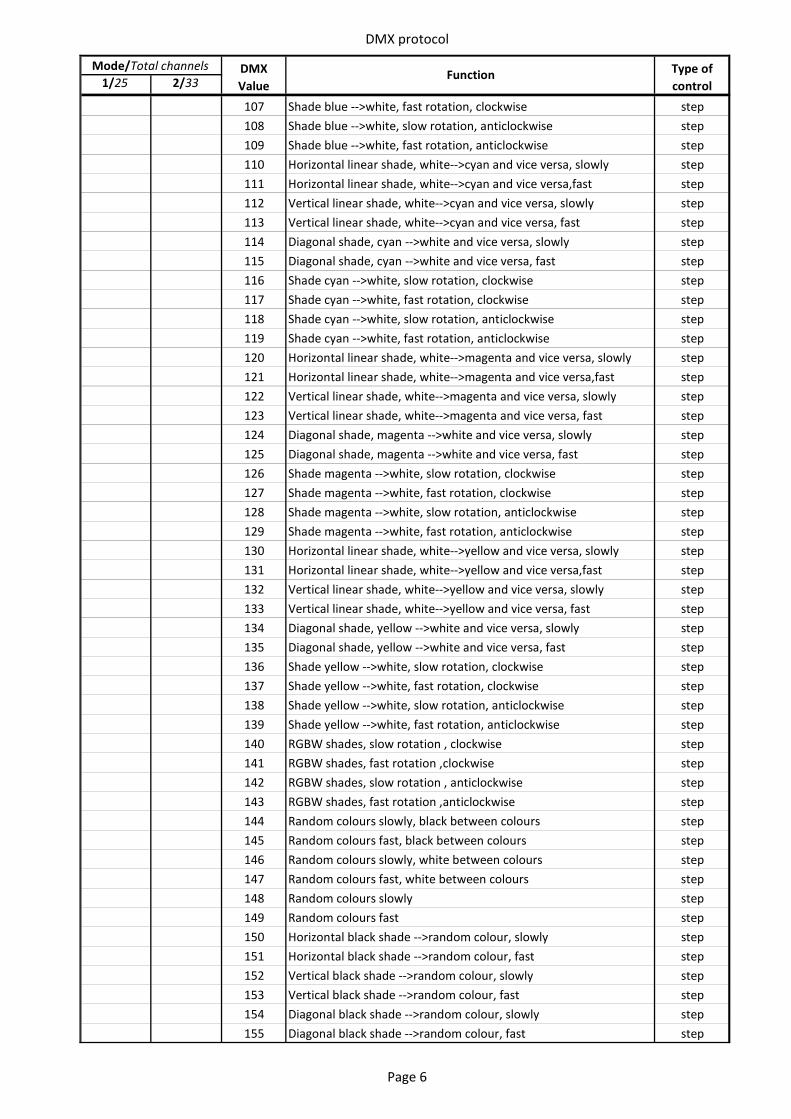
DMX protocol
1/25 2/33DMX Value
Function Type of control
Mode/Total channels
107 Shade blue -->white, fast rotation, clockwise step108 Shade blue -->white, slow rotation, anticlockwise step109 Shade blue -->white, fast rotation, anticlockwise step110 Horizontal linear shade, white-->cyan and vice versa, slowly step111 Horizontal linear shade, white-->cyan and vice versa,fast step112 Vertical linear shade, white-->cyan and vice versa, slowly step113 Vertical linear shade, white-->cyan and vice versa, fast step114 Diagonal shade, cyan -->white and vice versa, slowly step115 Diagonal shade, cyan -->white and vice versa, fast step116 Shade cyan -->white, slow rotation, clockwise step117 Shade cyan -->white, fast rotation, clockwise step118 Shade cyan -->white, slow rotation, anticlockwise step119 Shade cyan -->white, fast rotation, anticlockwise step120 Horizontal linear shade, white-->magenta and vice versa, slowly step121 Horizontal linear shade, white-->magenta and vice versa,fast step122 Vertical linear shade, white-->magenta and vice versa, slowly step123 Vertical linear shade, white-->magenta and vice versa, fast step124 Diagonal shade, magenta -->white and vice versa, slowly step125 Diagonal shade, magenta -->white and vice versa, fast step126 Shade magenta -->white, slow rotation, clockwise step127 Shade magenta -->white, fast rotation, clockwise step128 Shade magenta -->white, slow rotation, anticlockwise step129 Shade magenta -->white, fast rotation, anticlockwise step130 Horizontal linear shade, white-->yellow and vice versa, slowly step131 Horizontal linear shade, white-->yellow and vice versa,fast step132 Vertical linear shade, white-->yellow and vice versa, slowly step133 Vertical linear shade, white-->yellow and vice versa, fast step134 Diagonal shade, yellow -->white and vice versa, slowly step135 Diagonal shade, yellow -->white and vice versa, fast step136 Shade yellow -->white, slow rotation, clockwise step137 Shade yellow -->white, fast rotation, clockwise step138 Shade yellow -->white, slow rotation, anticlockwise step139 Shade yellow -->white, fast rotation, anticlockwise step140 RGBW shades, slow rotation , clockwise step141 RGBW shades, fast rotation ,clockwise step142 RGBW shades, slow rotation , anticlockwise step143 RGBW shades, fast rotation ,anticlockwise step144 Random colours slowly, black between colours step145 Random colours fast, black between colours step146 Random colours slowly, white between colours step147 Random colours fast, white between colours step148 Random colours slowly step149 Random colours fast step150 Horizontal black shade -->random colour, slowly step151 Horizontal black shade -->random colour, fast step152 Vertical black shade -->random colour, slowly step153 Vertical black shade -->random colour, fast step154 Diagonal black shade -->random colour, slowly step155 Diagonal black shade -->random colour, fast step
Page 6
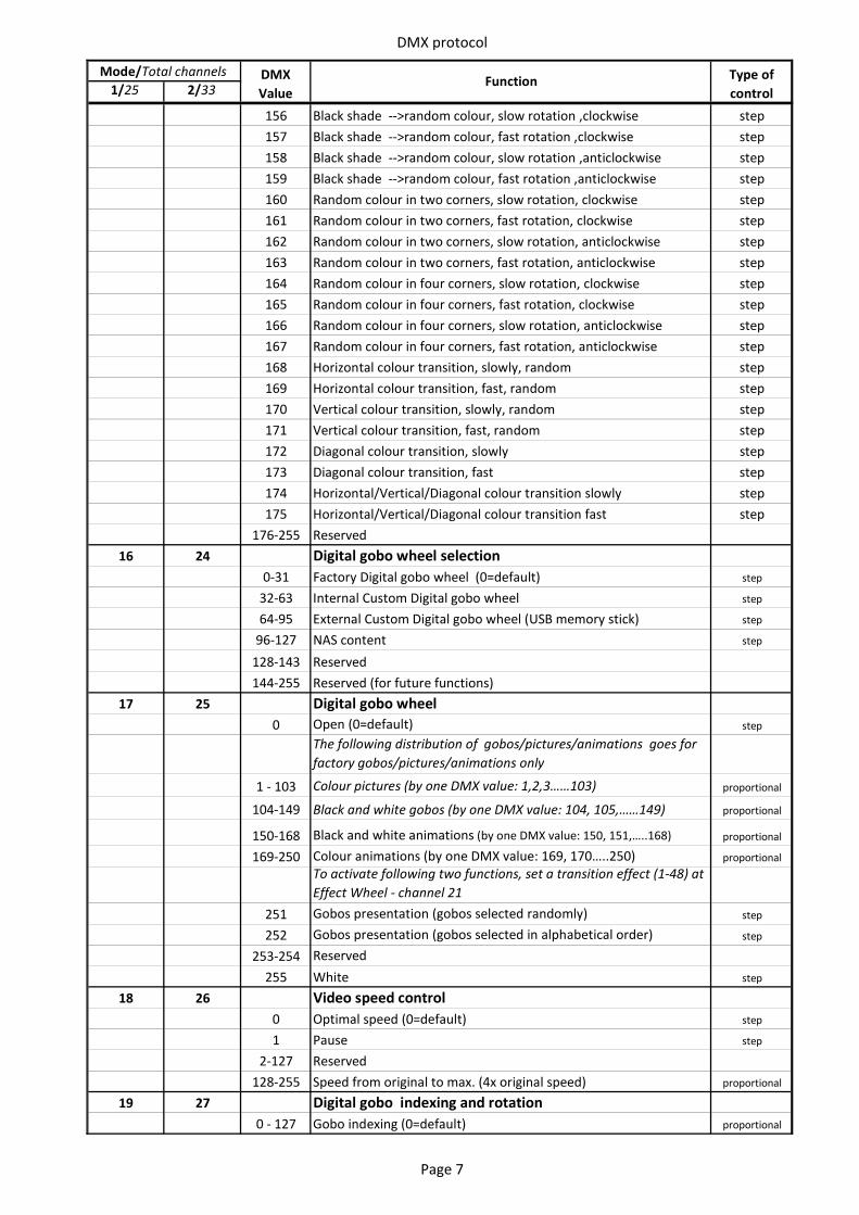
DMX protocol
1/25 2/33DMX Value
Function Type of control
Mode/Total channels
156 Black shade -->random colour, slow rotation ,clockwise step157 Black shade -->random colour, fast rotation ,clockwise step158 Black shade -->random colour, slow rotation ,anticlockwise step159 Black shade -->random colour, fast rotation ,anticlockwise step160 Random colour in two corners, slow rotation, clockwise step161 Random colour in two corners, fast rotation, clockwise step162 Random colour in two corners, slow rotation, anticlockwise step163 Random colour in two corners, fast rotation, anticlockwise step164 Random colour in four corners, slow rotation, clockwise step165 Random colour in four corners, fast rotation, clockwise step166 Random colour in four corners, slow rotation, anticlockwise step167 Random colour in four corners, fast rotation, anticlockwise step168 Horizontal colour transition, slowly, random step169 Horizontal colour transition, fast, random step170 Vertical colour transition, slowly, random step171 Vertical colour transition, fast, random step172 Diagonal colour transition, slowly step173 Diagonal colour transition, fast step174 Horizontal/Vertical/Diagonal colour transition slowly step175 Horizontal/Vertical/Diagonal colour transition fast step
176-255 Reserved16 24 Digital gobo wheel selection
0-31 Factory Digital gobo wheel (0=default) step
32-63 Internal Custom Digital gobo wheel step
64-95 External Custom Digital gobo wheel (USB memory stick) step
96-127 NAS content step
128-143 Reserved144-255 Reserved (for future functions)
17 25 Digital gobo wheel0 Open (0=default) step
The following distribution of gobos/pictures/animations goes for factory gobos/pictures/animations only
1 - 103 Colour pictures (by one DMX value: 1,2,3……103) proportional
104-149 Black and white gobos (by one DMX value: 104, 105,……149) proportional
150-168 Black and white animations (by one DMX value: 150, 151,…..168) proportional
169-250 Colour animations (by one DMX value: 169, 170…..250) proportionalTo activate following two functions, set a transition effect (1-48) at Effect Wheel - channel 21
251 Gobos presentation (gobos selected randomly) step
252 Gobos presentation (gobos selected in alphabetical order) step
253-254 Reserved255 White step
18 26 Video speed control0 Optimal speed (0=default) step
1 Pause step
2-127 Reserved128-255 Speed from original to max. (4x original speed) proportional
19 27 Digital gobo indexing and rotation0 - 127 Gobo indexing (0=default) proportional
Page 7
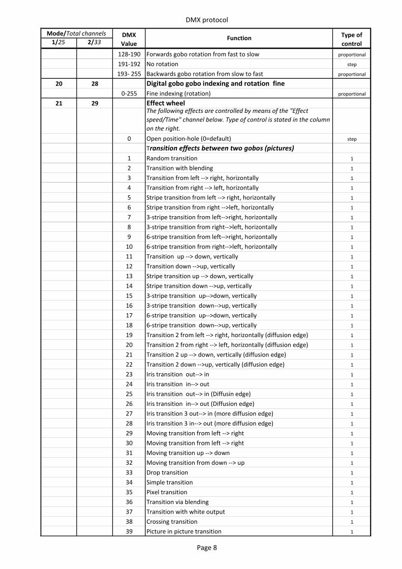
DMX protocol
1/25 2/33DMX Value
Function Type of control
Mode/Total channels
128-190 Forwards gobo rotation from fast to slow proportional
191-192 No rotation step
193- 255 Backwards gobo rotation from slow to fast proportional
20 28 Digital gobo gobo indexing and rotation fine0-255 Fine indexing (rotation) proportional
21 29 Effect wheelThe following effects are controlled by means of the "Effect speed/Time" channel below. Type of control is stated in the column on the right.
0 Open position-hole (0=default) step
Transition effects between two gobos (pictures)1 Random transition 1
2 Transition with blending 1
3 Transition from left --> right, horizontally 1
4 Transition from right --> left, horizontally 1
5 Stripe transition from left --> right, horizontally 1
6 Stripe transition from right -->left, horizontally 1
7 3-stripe transition from left-->right, horizontally 1
8 3-stripe transition from right-->left, horizontally 1
9 6-stripe transition from left-->right, horizontally 1
10 6-stripe transition from right-->left, horizontally 1
11 Transition up --> down, vertically 1
12 Transition down -->up, vertically 1
13 Stripe transition up --> down, vertically 1
14 Stripe transition down -->up, vertically 1
15 3-stripe transition up-->down, vertically 1
16 3-stripe transition down-->up, vertically 1
17 6-stripe transition up-->down, vertically 1
18 6-stripe transition down-->up, vertically 1
19 Transition 2 from left --> right, horizontally (diffusion edge) 1
20 Transition 2 from right --> left, horizontally (diffusion edge) 1
21 Transition 2 up --> down, vertically (diffusion edge) 1
22 Transition 2 down -->up, vertically (diffusion edge) 1
23 Iris transition out--> in 1
24 Iris transition in--> out 1
25 Iris transition out--> in (Diffusin edge) 1
26 Iris transition in--> out (Diffusion edge) 1
27 Iris transition 3 out--> in (more diffusion edge) 1
28 Iris transition 3 in--> out (more diffusion edge) 1
29 Moving transition from left --> right 1
30 Moving transition from left --> right 1
31 Moving transition up --> down 1
32 Moving transition from down --> up 1
33 Drop transition 1
34 Simple transition 1
35 Pixel transition 1
36 Transition via blending 1
37 Transition with white output 1
38 Crossing transition 1
39 Picture in picture transition 1
Page 8
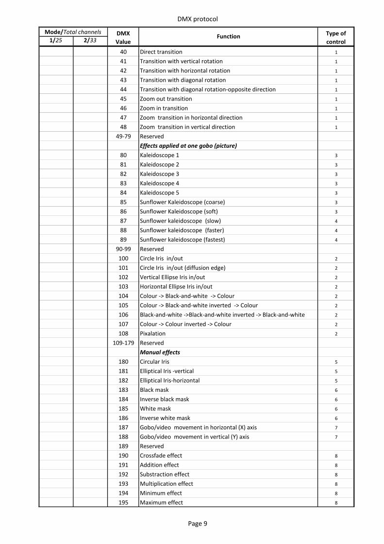
DMX protocol
1/25 2/33DMX Value
Function Type of control
Mode/Total channels
40 Direct transition 1
41 Transition with vertical rotation 1
42 Transition with horizontal rotation 1
43 Transition with diagonal rotation 1
44 Transition with diagonal rotation-opposite direction 1
45 Zoom out transition 1
46 Zoom in transition 1
47 Zoom transition in horizontal direction 1
48 Zoom transition in vertical direction 1
49-79 ReservedEffects applied at one gobo (picture)
80 Kaleidoscope 1 3
81 Kaleidoscope 2 3
82 Kaleidoscope 3 3
83 Kaleidoscope 4 3
84 Kaleidoscope 5 3
85 Sunflower Kaleidoscope (coarse) 3
86 Sunflower Kaleidoscope (soft) 3
87 Sunflower kaleidoscope (slow) 4
88 Sunflower kaleidoscope (faster) 4
89 Sunflower kaleidoscope (fastest) 4
90-99 Reserved100 Circle Iris in/out 2
101 Circle Iris in/out (diffusion edge) 2
102 Vertical Ellipse Iris in/out 2
103 Horizontal Ellipse Iris in/out 2
104 Colour -> Black-and-white -> Colour 2
105 Colour -> Black-and-white inverted -> Colour 2
106 Black-and-white ->Black-and-white inverted -> Black-and-white 2
107 Colour -> Colour inverted -> Colour 2
108 Pixalation 2
109-179 ReservedManual effects
180 Circular Iris 5
181 Elliptical Iris -vertical 5
182 Elliptical Iris-horizontal 5
183 Black mask 6
184 Inverse black mask 6
185 White mask 6
186 Inverse white mask 6
187 Gobo/video movement in horizontal (X) axis 7
188 Gobo/video movement in vertical (Y) axis 7
189 Reserved190 Crossfade effect 8
191 Addition effect 8
192 Substraction effect 8
193 Multiplication effect 8
194 Minimum effect 8
195 Maximum effect 8
Page 9
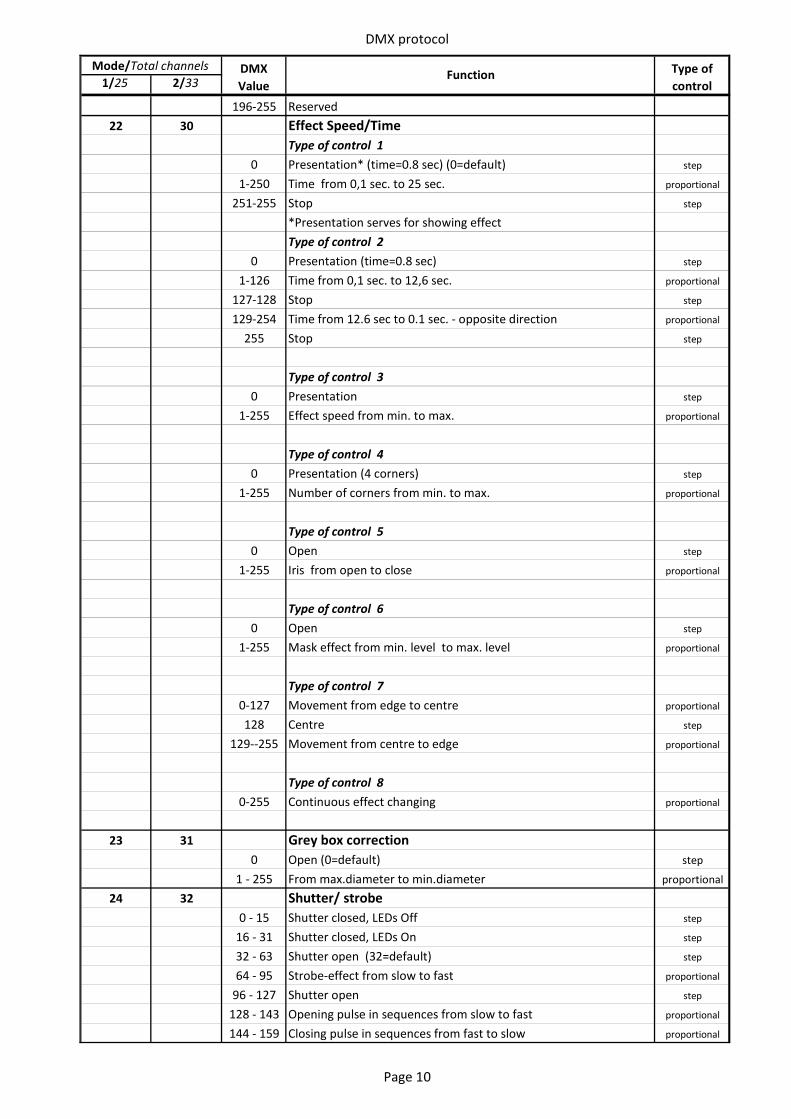
DMX protocol
1/25 2/33DMX Value
Function Type of control
Mode/Total channels
196-255 Reserved22 30 Effect Speed/Time
Type of control 10 Presentation* (time=0.8 sec) (0=default) step
1-250 Time from 0,1 sec. to 25 sec. proportional
251-255 Stop step
*Presentation serves for showing effectType of control 2
0 Presentation (time=0.8 sec) step
1-126 Time from 0,1 sec. to 12,6 sec. proportional
127-128 Stop step
129-254 Time from 12.6 sec to 0.1 sec. - opposite direction proportional
255 Stop step
Type of control 30 Presentation step
1-255 Effect speed from min. to max. proportional
Type of control 40 Presentation (4 corners) step
1-255 Number of corners from min. to max. proportional
Type of control 50 Open step
1-255 Iris from open to close proportional
Type of control 60 Open step
1-255 Mask effect from min. level to max. level proportional
Type of control 70-127 Movement from edge to centre proportional
128 Centre step
129--255 Movement from centre to edge proportional
Type of control 80-255 Continuous effect changing proportional
23 31 Grey box correction0 Open (0=default) step
1 - 255 From max.diameter to min.diameter proportional
24 32 Shutter/ strobe0 - 15 Shutter closed, LEDs Off step
16 - 31 Shutter closed, LEDs On step
32 - 63 Shutter open (32=default) step
64 - 95 Strobe-effect from slow to fast proportional
96 - 127 Shutter open step
128 - 143 Opening pulse in sequences from slow to fast proportional
144 - 159 Closing pulse in sequences from fast to slow proportional
Page 10
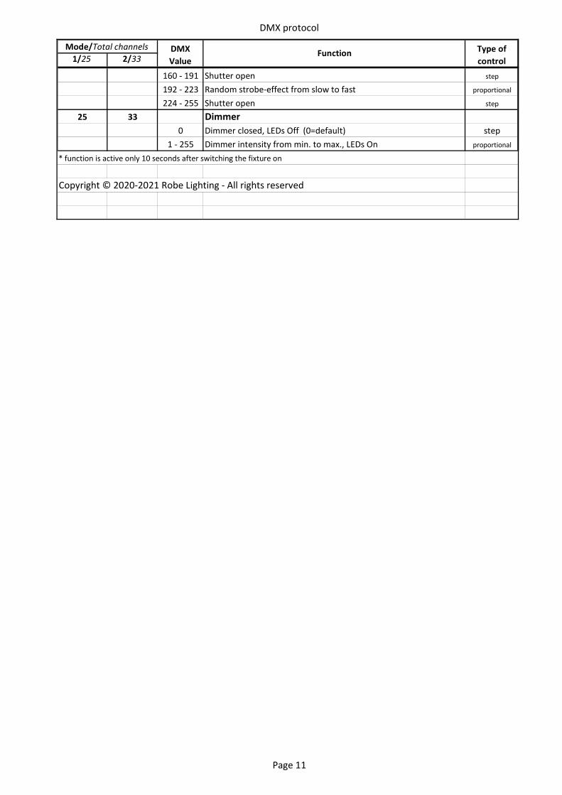
DMX protocol
1/25 2/33DMX Value
Function Type of control
Mode/Total channels
160 - 191 Shutter open step
192 - 223 Random strobe-effect from slow to fast proportional
224 - 255 Shutter open step
25 33 Dimmer 0 Dimmer closed, LEDs Off (0=default) step
1 - 255 Dimmer intensity from min. to max., LEDs On proportional
* function is active only 10 seconds after switching the fixture on
Copyright © 2020-2021 Robe Lighting - All rights reserved
Page 11