transformer protection terminal ret 521 c2 2.3 - abb
TRANSCRIPT

Page 1
(SE960158)
��������� ��������� ������� ��� ����������
1MRK 504 019-BEN
Issued March 2003Revision: A
Data subject to change without notice
�������� • Pre-configured transformer terminal for cost-effective engineering and commis-sioning
• Easy to order
• Multiple function transformer protection ter-minal in a compact design
• Suitable for power transformers and gener-ator-transformer blocks
• Two-winding power transformer application
• No interposing Current Transformers required
• Application flexibility through generous set-tings
• Extended frequency range by frequency tracking and filter adaptation
• Function modular and type tested software
• Transformer differential protection
- for two-winding transformers
- Through-fault stability by settable cur-rent bias characteristics
- Enhanced through-fault stability for multi-breaker arrangements
- Inrush restraint with two selectable com-binations of waveform and 2nd har-monic methods. Settable crossblocking between phases
- Overexcitation restraint with 5th har-monic
- Internal CT ratio and vector group adap-tation
- Settable zero sequence current elimina-tion
• Two three-phase nondirectional time delayed overcurrent protections with inverse and definite time characteristics connected to the HV and LV windings
• Two restricted earth fault protections con-nected to the LV and HV windings. The protection is based on the low impedance principle and provided with a directional element
• Two nondirectional time delayed earth fault protections with inverse and definite time characteristics connected to the LV and HV windings. 2nd harmonic restraining can be chosen if required
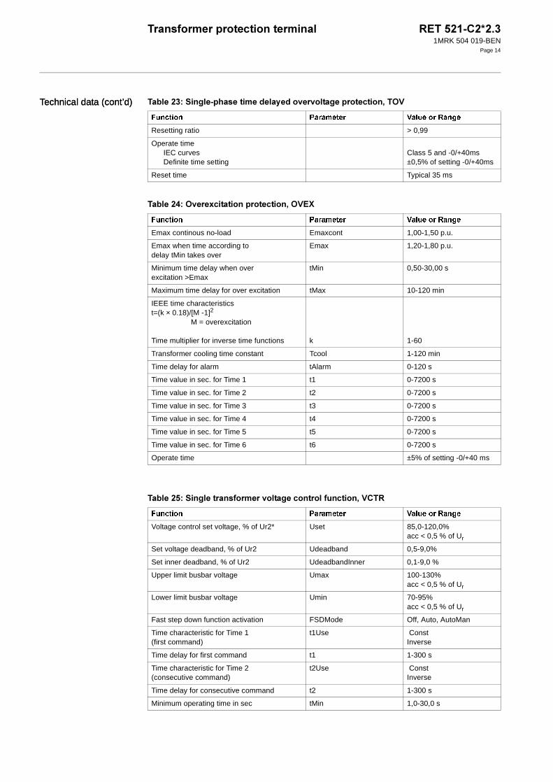
• A single-phase time delayed overvoltage protection measuring the phase-phase voltage with inverse and definite time char-acteristics connected to the LV winding

��������� ��������� ������� ��� ����������1MRK 504 019-BEN
Page 2
Features (cont’d) • An overexcitation protection based on V/Hz measurement with IEEE inverse time or transformer adapted characteristic and connected to the LV winding
• Voltage regulation for single transformer with on load tap changer
• Additional programmable logic with inputs and outputs, And-, Or-gates, SR-gates, timers and trip logic for trip and/or indica-tion of external protection features (Buch-holz, temperature, etc.) are available using the CAP-tool
• Display of service values
• Display of event records and trip values
• Continuous self monitoring and diagnostics
• Disturbance recording and data storage for presentation on PC
• Front mounted menu driven display with key pad and front port connector for PC
• Remote data communication with up to 2 ports for station control and station monitor-ing systems
• Available for 19 inch rack mounting in a panel, surface or flush mounting
• Hardware:
- One binary input module, one binary output module and one mA analog input module (4-20 mA)
- One analog input module
• Hardware options:
- Separate Combitest test switch for reli-able and safe testing
- On/Off switch for dc supply
- Mounting details for IP 40 and IP 54
���������� The numerical transformer terminal RET 521-C2 is designed for fast and selective pro-tection and control of two-winding transform-ers, auto-transformers and generator-transformer blocks.
The RET 521-C2 has low requirements on the main Current Transformers and no inter-posing CTs are necessary.
Flexibility is provided to cover for different applications in form of transformer size, vec-tor groups and system neutral earthing. For big and important transformers such as gener-ator-transformer blocks or large auto trans-formers two RET 521-C2 can be used to obtain redundancy.
Using programmable logic provides a very compact design for protection and control. For changes in the programmable logic the CAP-tool is required.
The RET 521-C2 includes setting adaptation to power transformer rating and instrument transformer ratios to allow protection settings in percent (%), of the power transformer rat-ing, thus facilitating the protection settings to an optimum.
The RET 521-C2 can be applied for 2-wind-ing applications as indicated below in Figure 1:
Figure 1: An application example
������� �����������
2-winding power trans-former
2-winding power trans-former with unconnected delta tertiary winding
Overtemp. etc.
TOC
3I>
Logic
Comm.
REF
REFDIFP
I/O
Trip
TOC
3I>
3Id/I
(xx0
0000
627.
eps)
>
TOV ,OVEX, VCTR
TEF
REFREF
TEF
Z/0

��������� ��������� ������� ��� ����������1MRK 504 019-BEN
Page 3
��������� ��������� ��������� �� ��� ������ !"�#The differential protection for two windings is one of the most important functions for fast and selective protection of transformers. The RET 521-C2 is provided with internal setta-ble adaptation for CT ratio matching and vec-tor groups, which allows connection directly to Y-connected main CTs. Zero sequence cur-rent elimination can be included in order to increase the sensitivity but it can also by set-ting be excluded. All current inputs are pro-vided with restraint features. The setting facilities cover for application of the differen-tial protection to power transformers with or without tap changer. An adaptive differential feature is included for through-faults. By introducing the tap changer position to RET 521-C2, the differential protection pick-up can be set to optimum sensitivity covering low level internal fault currents.
Stabilisation is included to avoid differential protection tripping for inrush currents and for overexcitation. Stabilisation is also included for system recovery inrush and CT saturation for external faults. Crossblocking between phases is normally used, but can be switched off.
A fast high set unrestrained differential cur-rent protection is also included for high speed tripping at high internal fault currents.
Service values for differential currents, bias current and tap position are available.
�$�����$��� ����������� ���� ����%�� �&�������� ��������� �'�Two units of the three-phase nondirectionel time delayed overcurrent protection are included.
The overcurrent protection is recommended as a backup protection for transformer faults or network faults. The overcurrent protection is provided with two settable current levels. The lower level can be selected with definite or inverse time characteristic, and the higher level can be selected with definite character-istic only. Both levels have separate blocking inputs.
Service value for the highest current is avail-able.
���������� ����$ ���� ��������� ���Two units of the restricted earth fault protec-tion are included.
REF is an instantaneous earth current differ-ential protection for solidly or low impedance earthed systems. It is applied for each trans-former winding. The protection is a stabilised low impedance type and is unaffected by inrush currents or external faults. The protec-tion is also stabilised against CT saturation. A directional element is included in the protec-tion.
Service values for differential current and bias current are available.
(����������� ���� ����%�� ����$ ���� ��������� ���Two units of the nondirectional time delayed earth fault protection are included.
The earth fault protection is recommended as a backup protection for transformer faults or network faults. The earth fault protection is provided with two settable current levels. The lower level can be selected with definite or inverse time characteristic, and the higher level has definite characteristic only. Both levels can also be provided with a 2nd har-monic restraint for inrush currents. The earth fault protection can be connected to a CT in the neutral point of the transformer or to residually connected CT´s.
Service values for residual current is avail-able.
)������$��� ���� ����%�� �&��&������ ��������� �'*A single-phase time delayed overvoltage pro-tection measuring the phase-phase voltage is included.
The overvoltage protection is recommended as backup for sustained system overvoltages. The overvoltage protection is provided with two settable voltage levels, and both levels are provided with definite time delay. The low stage can alternatively have an inverse time delay.
Service values for the phase voltage is avail-able.
'&���+������� ��������� ,*-./0 '*�1An overexcitation protection is included. Using the CAP-tool the protection can be connected to any side of the power trans-former. However the side with the voltage regulation taps shall be avoided.

��������� ��������� ������� ��� ����������1MRK 504 019-BEN
Page 4
Application (cont’d)Application (cont’d) The overexcitation protection is based on voltage/frequency (V/Hz) measurement. The IEEE trip time inverse characteristic can be set to follow the transformer characteristic and a cooling time memory is included. The trip time characteristic is also provided with definite minimum and maximum times.
As an alternative a transformer adapted time delay characteristic can be set and used for close adaptation to the transformer capability characteristic.
Separate trip and alarm outputs are included.
Service values for relative excitation status voltage/frequency, thermal status and time-to-trip are available.
*������ ������ �� � ����� ��������� *���The voltage control function included in RET 521-C2 is used to maintain a constant user preset voltage at the low voltage side of the transformer, i.e. at the busbar or at the feeder ends. Constant voltage is obtained by control-ling the tap changer position by raise and lower commands. The delay for the regulat-ing command can be of inverse or definite type. Blocking is included for overcurrent and undervoltage, power system emergen-cies and tap changer end positions. Line drop compensation is included. A load shedding based on voltage reduction is also included. Number of tap changer operations can be recorded for determining the service inter-vals. Remote or local command possibilities are included. Alarms from the tap changer auxiliary equipment (binary contacts) can be connected to the voltage control function. The tap changer position is monitored by a 4-20 mA-input to the voltage control function. (17 positions are considered in the configura-tion).
If the number of tap position are other than 17, the tap position number on the MIM block in the configuration has to be changed by use of the CAP-tool.
Service values for busbar voltage, compen-sated voltage, actual set voltage, load voltage adjustment, tap changer position, contact life calculation and no of operation counter are available
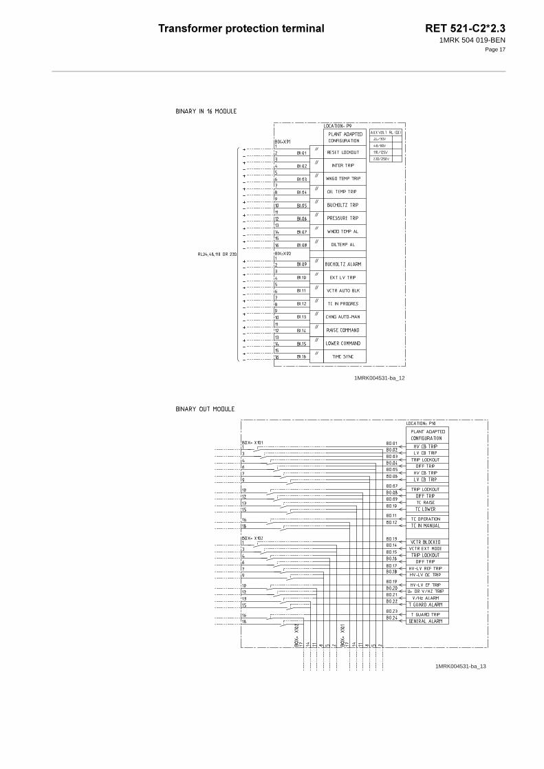
"��� ���� �����+External contacts, e.g. from transformer over-temperature devices and Buchholz gas detec-tor, can be connected via Binary Inputs.
Logic can be arranged for alarm, event log-ging and tripping. For redundancy reasons it is recommended to route tripping from the Buchholz or overpressure device in parallel to RET 521-C2.
������� �����+The tripping commands are configured to trip logic blocks, which then are configured to the tripping output relays. Each trip logic block (OR gate) has 16 inputs. 3 trip logic blocks are used in the standard configuration. An additional 9 blocks are available using the CAP-tool.
��������� �����Additional logic elements in the form of 40 AND-gates, 40 OR-gates, 20 inverters, 25 timers, 20 pulse elements and 10 SR-gates are available. Some are already used in the con-figuration and the rest can be combined to suit particular requirements using the CAP-tool.
������� �������Terminal diagrams for the connection of the analog inputs, the binary inputs/outputs, the logical circuits and the protection modules, the control modules and the monitoring mod-ules are shown in “Terminal diagrams” on page 16 and forward.
#�������� �������RET 521-C2 has wide setting facilities to ensure application flexibility. Factory default settings are chosen to indicate typical setting values or choices. The settings are organised as general settings and settings for each sepa-rate function.
The main data (ratings) of the protected trans-former and ratios of the instrument transform-ers are entered in the terminal setting and configuration menus. Most of the setting parameters of the particular functions can then be made as per unit (p.u.) or percent (%) values related to the power transformer rat-ing. For some protections there also exist a possibility to define the rated value in the set-ting menu to another value than the power transformer rating. Most timers are set in sec-onds. There is a possibility to enter one to four complete groups of settings. It is then easy to switch between these groups locally or from remote.
Settings can be changed from the front Human-Machine-Interface (HMI), or by a portable personal computer (PC), with a parameter setting program (PST), connected

��������� ��������� ������� ��� ����������1MRK 504 019-BEN
Page 5
to a fibre-optic connector socket at the front, or from another location over a data commu-nication system.
"�������� �&��� �� ���&��� &�����Operation indications and time-tagged events are available from the front HMI or a con-nected PC and from another location over a data communication system. Actual input quantity values, load, differential current and other service values can also be read from the terminal.
!�����2��� ��������Sampled data from a disturbance, like a trip-ping operation, can be stored and made avail-able for oscillographic presentation and
evaluation on a front connected PC or from another location over a data communication system, to which the disturbance files are transferred. This function stores continu-ously sampled data in a cyclic buffer. At selectable trigger conditions the data are stored, so that both prefault and fault data are saved.
!��� �����������Two remote communication ports for SPA and LON can be included. They enable co-operation with a station monitoring system (SMS) including a remotely located PC, and a station control system (SCS).
!���� The physical design of terminal RET 521-C2 is in line with the products in the REx 500-series. It is housed in painted sheet steel enclosure suitable for different mounting by use of particular mounting accessories. Wire connections are made at the rear side at termi-nals of compression type tightened by a screw. Fibre optic wires for data communica-tion are also connected at the rear side. On the front is a HMI-panel and socket with an optic interface for a specific cable to a portable PC.
Behind the front there is an interconnection board, a motherboard, to which printed board assemblies (PBAs) are plugged in from the rear side. The input module for analog AC quantities is fixed mounted and the connec-tion terminal for these circuits are also fixed mounted. The connection terminals for the DC contact circuits are of the multipole detachable type so as to facilitate disconnec-tion for exchange of PBAs.
The following modules are included in the RET521-C2 terminal:
• One analog input module for 8 currents and 2 voltages with galvanic separation and adaptation of the AC signals. The ana-log input module also contains an analog
to digital converter (A/D-converter) which provides the necessary conversion and some filtering.
• Processor modules with data processing for the protection as well as other func-tions and communication. As an option two communication interfaces can be added for connection to a station monitor-ing system (SMS) including a remotely located PC and a station control system (SCS).
• Power supply module with DC/DC con-verter for the electronic circuits.
• One binary input module, BIM, with 16 binary inputs and one binary output mod-ule, BOM, with 24 output relay contacts are included.
• One mA-analog input board with 6 chan-nels for 4-20 mA is included.
• The front HMI panel includes three light-emitting diodes (LEDs), one LCD display with 4 lines times 16 characters. There is also a six button key pad and a fibre-optic connector socket, for connection to the serial port of a portable PC by means of a special interface cable.

��������� ��������� ������� ��� ����������1MRK 504 019-BEN
Page 6
���$���� ����
��2�� �3 �������� 4�������� ����� &����� �� ������
�������� ������ � ������ ����� ������������
CurrentBurden
Ir = 1 A or 5 A< 0,25 VA at Ir
(0,2-30) x Ir(0,2-4) x Ir continu-ously
(0,03 - 100 x Ir) 100 x Ir for 1 s*
AC voltage Ph-Ph**Burden
Ur = 100/110/115/120 V< 0,2 VA at Ur
80-120% of Ur 1,5 x Ur continuously2,5 x Ur for 10 s
Frequency fr = 50/60 Hz ±2,5 Hz ±5 Hz
Frequency with increased range fr = 50/60 Hz (0,7-1,2) x fr Hz (0,65-1,25) x fr Hz
Auxiliary DC voltage EL
Power consumptionBasic terminal (2 AIM, 1 BOM, 1 BIM, 1 IOM and 1 MIM) and no activated relay outputsAuxiliary DC power in-rush
EL = 110/125 VEL = 220/250 V
< 35 W
110 VDC, <15 A, 0,1 ms 220 VDC, <30 A, 0,1 ms
±20%±20%
±20%±20%
Binary input (8) /output (12) moduleDC voltage RL
power consumptioneach I/O boardeach output relayRL = 24/30 VRL = 48/60 VRL = 110/125 VRL = 220/250 V
RL = 24/30 VRL = 48/60 VURL = 110/125 VRL = 220/250 V
≤ 1 W≤ 0,15 Wmax. 0,05 W/inputmax. 0,1 W/inputmax. 0,2 W/inputmax. 0,4 W/input
±20%±20%±20%±20%
±20%±20%±20%±20%
Binary input(16) moduleDC voltage
power consumptioneach I/O boardRL = 24/30 VRL = 48/60 VRL = 110/125 VRL = 220/250 V
RL = 24/30 VRL = 48/60 VRL = 110/125 VRL = 220/250 V
≤0,5 Wmax. 0,05 W/inputmax. 0,1 W/inputmax. 0,2 W/inputmax. 0,4 W/input
±20%±20%±20%±20%
±20%±20%±20%±20%
Binary output (24/12) modulepower consumption
each output boardeach output relay
≤ 1 W≤ 0,25 W
mA input moduleinput rangeinput resistance
power consumptioneach mA moduleeach mA input channel
±20 mARin = 194 ohm
≤4 W≤0,1W
Ambient temperature 20°C -5°C to +55°C
Ripple in dc auxiliary voltage max. 2% max. 12% Full wave rectified

��������� ��������� ������� ��� ����������1MRK 504 019-BEN
Page 7
Relative humidity 10-90% 10-90% 0-95%
* Max 350 A for 1 s when COMBIFLEX test switch is used
** Ph-ph voltage may also be directly connected across the analog voltage inputs
��2�� �3 "������ ������ #�������2�� ������
�������� ������������� ����� �������������������
Ambient temperature 0,01%/1°C Correct function
Frequency dependence (without extended frequency range)
fr ± 2,5 Hz for 50 Hzfr ± 2,5 Hz for 60 Hz
± 3,0 %
Frequency dependence (with extended frequency range)
(0,7-1,2) x fr ± 2,0 %
Harmonic frequency dependence (10, 20 and 50% content)
2:nd 3:rd and 5:th harmonic of fr
± 1,0 %
Ripple in auxiliary DC voltage negligible Correct function
Interruption in auxiliary DC voltagewithout resettingno unwanted function
< 50 ms0 - ∞
< 50 ms0 - ∞
��2�� �3 �������������� �������2����% ,�5�0 ������% �����
��� ���������� �� �������������
1 MHz burst disturbance 2,5 kV IEC 60255-22-1, Class III
Electrostatic dischargeDirect application
Indirect application
8 kV, air discharge6 kV, contact discharge6 kV, contact discharge
IEC 60255-22-2, Class III
IEC 61000-4-2, Class III
Fast transient disturbance 4 kV IEC 60255-22-4, Class IV
Surge immunity test 1-2 kV, 1,2/50 µs, high energy IEC 61000-4-5, Class III
Radiated electromagnetic fielddisturbance
10 V/m, 26-1000 MHz IEC 61000-4-3, level 3
Radiated electromagnetic fielddisturbance GSM
10 V/m, 900 MHz ENV 50204
Conducted electromagnetic fielddisturbance
10 V/m, 0,15-80 MHz IEC 61000-4-6, level 3
��2�� 63 �������������� �������2����% ,�5�0 ������� �����
��� ���������� �� �������������
Electromagnetic emission radiated 30-1000 MHz, class A EN 55011
Electromagnetic emission conducted 0,15 - 30 MHz, class A EN 55081-2
��2�� �3 �������� 4�������� ����� &����� �� ������
�������� ������ � ������ ����� ������������

��������� ��������� ������� ��� ����������1MRK 504 019-BEN
Page 8
Technical data (cont’d)Technical data (cont’d)
��2�� �3 "������� �����
��� ���������� �� �������������
Dielectric test 2,0 kV ac 1 min IEC 60255-5
Impulse voltage test 5 kV, 1,2/50 µs, 0,5 J IEC 60255-5
Insulation resistance > 100 Mohm at 500 V dc IEC 60255-5
��2�� 73 ������8
��� ���������� �� �������������
Immunity EN 50082-2
Emissivity EN 50081-2
Low voltage directive EN 50178
��2�� 93 5��$����� �����
��� ���������� �� �������������
Vibration Class I IEC 60255-21-1
Shock and bump Class I IEC 60255-21-2
Seismic Class I IEC 60255-21-3
��2�� :3 ������ ���� ,������� �������3 "�� 7;���0
�������������������� �������������� �� ���
���������� �� ���
����� ���� ��
Max. system voltage 250 V ac, dc 250 V ac, dc
Test voltage across open contact, 1 min 1,0 kV rms 800 V, dc
Current carrying capacitycontinuous1 s
8 A10 A
8 A10 A
Making capacity at inductive loadwith L/R > 10 ms
0,2 s 1,0 s
30 A10 A
0,4 A0,4 A
Breaking capacity for ac, cosϕ > 0,4 250 V/8,0 A 250 V/8,0 A
Breaking capacity for dcwith L/R < 40 ms
48 V/1 A110 V/0,4 A220 V/0,2 A250 V/0,15 A
48 V/1 A110 V/0,4 A220 V/0,2 A250 V/0,15 A
Maximum capacitive load 10 nF

��������� ��������� ������� ��� ����������1MRK 504 019-BEN
Page 9
��2�� <3 ������� �%����
!����������� ������ ���
"�#�����
���������
"�#����� ���
����������
"�#����� ���
$��
Voltage connectors 250 V AC 2,5 mm2
2 x 1 mm210 A 30 A
Current connectors 250 V AC 4 mm2 20 A 500 A
Fiber connectors Glass: Bayonet STPlastic: Snap in Simplex Latching
��2�� �;3 ��������� ������ ����
Weight approximate 10 kg
DimensionsWidthHeightDepth
336 mm (3/4 of 19”)6U = 267 mm245 mm
Water and dust protection level Front IP 40 ( IP 54 with sealing strip )Sides IP 30Back IP 20
Storage temperature -40°C to +70°C
��2�� ��3 ���� �����������
�������� %� �
Protocol SPA
Communication speed 300, 1200, 2400, 4800, 9600, 19200 or 38400 baude
Slave number 1 to 899
Connectors special electric/optic cable
��2�� ��3 )����� ����������� ,)#�0
�������� %� �
Protocol SPA
Communication speed 300, 1200, 2400, 4800, 9600, 19200 or 38400 baude
Slave number 1 to 899
Connectors and optical fibres glass or plastic
��2�� ��3 )����� ����������� ,='(0
�������� %� �
Protocol LON
Communication speed 1,25 Mbit/s
Connectors and optical fibres glass or plastic

��������� ��������� ������� ��� ����������1MRK 504 019-BEN
Page 10
Technical data (cont’d)Technical data (cont’d)
��2�� �63 �&�� ��������
�������� %� �
Time tagging resolution 1 ms
Event buffering capacityMax. number of events/disturbance reportMax. number of disturbance reports
Time tagging error with synchronisationusing LON and minute pulse
Time tagging error without synchronisation
15010
± 1 ms typical
± 10ms/hour
��2�� ��3 )��&��� &����� �� ���� 4��������
�������� ������ �����
Frequency (0,7 -1,2) x fr acc ± 2 mHz at three phase connectionacc ± 50 mHz at single phase connection
Current (0,1 - 4,0) x Ir
Voltage (0,1 - 1,5) x Ur
Angles 0,0 - 359,9 degrees
��2�� �73 !�����2��� ��������
�������� &����������
Number of binary inputs 0-48
Number of analog inputs 0-10
Sampling rate 1 kHz or 1,2 kHz for 50 and 60 Hz respectively
Recording bandwidth (5-500) Hz or (6-600) Hz fixed
Over triggering (0,00-50,00) x rated value (Ur or Ir)
Under triggering (0,00-2,00) x rated value (Ur or Ir)
Pre-fault time (50-300) ms in steps of 10 ms
Post fault time (100-3000) ms in steps of 100 ms
Limit time (500-4000) ms in steps of 100 ms
Number of recorded disturbances Max. 10 disturbances
�������� %� �
Voltage channelsdynamic rangeresolutionaccuracy at rated frequency fr
U<UrU>Ur
(0,01-2,0) x Ur at 100 V sec.0,1% of Ur
≤1% of Ur≤1% of U

��������� ��������� ������� ��� ����������1MRK 504 019-BEN
Page 11
Current channelsdynamic range
without DC offsetwith full DC offset
resolutionaccuracy at rated frequency fr
I<IrI>Ir
(0,01-85) x Ir(0,01-40) x Ir≤0,5% of Ir
≤1% of Ir≤1% of I (current value)
Total recording time with 10 analog and 48 digital signals recorder maximum 40 s
Built-in calendar For 30 years including leap years
��2�� �93 ��������� ,�2>���0 ����
�������� '������ %� ���������
Rated power 2 winding Sr 0,1-9999,9 MVA
Rated current primary winding in A Ir1 1-99999 A
Rated current secondary winding in A Ir2 1-99999 A
Rated voltage primary winding in kV Ur1 1,0-999,9 kV
Rated voltage secondary winding in kV Ur2 1,0-999,9 kV
Vector group compensation(For different groups, Yy0, Yd1, Dy11.. etc.)
VectorGrp2WV 1-24
��2�� �:3 ��������� ������� ����������
�������� '������ %� ���������
Used input tap for CT on AIM card in A InputCTTap Input 1A / Input 5A
Rated CT primary current in A CTprim 1-99999
Rated CT secondary current in A CTsec 1-5 (step 1)
Current transformer earthing, Towards power transformer/Towards bus
CTstarpoint ToObject, FromObject
Rated VT primary voltage in kV VTprim 0,1-999,9
Rated VT secondary voltage in V VTsec 1-999
��2�� �<3 ��������� ��������� ��������� �� ��� ������ !"�#
�������� '������ %� ���������
Current bias CharactNo Selectable characteristics
Inrush Stabilisation setting StabByOption Wave form and second harmonic selections
Inrush restraint I2/I1ratio 10-25%
Overexcitation restraint I5/I1ratio 10-50%
Basic diff. current, % of object Ir Idmin 10-50%
High, non-restraint diff. current, % of object Ir Idunre 500-2500%
Zero Sequence Current Subtraction ZSCSub Off/On
Operation crossblocking CrossBlock Off/On
Number of taps NoOfTaps 1 - 64
Rated tap RatedTap 1 - 64
��2�� �73 !�����2��� ��������

��������� ��������� ������� ��� ����������1MRK 504 019-BEN
Page 12
Technical data (cont’d)Technical data (cont’d)
Voltage for minimum tap (tap1) in kV MinTapVoltage 0,1 - 999,9
Voltage for maximum tap in kV MaxTapVoltage 0,1 - 999,9
Operate timeat diff. current I = 2 x Irat diff. current I = 10 x Irat diff. current I = 2 x Idunre
33 ms, typically30 ms, typically20 ms, typically
Reset time Typical 15 ms
��2�� �;3 �$�����$��� ����������� ���� ����%�� �&�������� ��������� �'�
�������� '������ %� ���������
Level 1Operate current, % of object Ir or user defined IrTime characteristics
IsetLowCurveType
10-500%DEF, NI, VI, EI, LI
Definite time setting tDefLow 0,03- 240,00 s
Inverse time characteristics t=(k × T)/[(I/Is1)e -1]
Is1 = IsetLow
Time multiplierDefinite minimum time
ktMin
Acc. to IEC 60255-3Normal inverse, Type A Very inverse, Type B Extremely inverse, Type CLong time inverse0,05-1,100,05-1,00 s
High set current, % of object Ir or user defined IrTime setting
IsetHightDefHigh
10-2000%0,03-5,00 s
Selection of nondirectional, forward or reverse direction for lowset
DirectionLow NonDir, Forward, Reverse
Selection of nondirectional forward or reversedirection for highset
DirectionHigh NonDir, Forward, Reverse
Relay Characteristic Angle in degrees rca -50 to -20 degrees
Relay Operate Angle in degrees roa ±60 to ±90 degrees
Resetting ratio > 0,95
Operate timeIEC curves
Definite time settingClass 5 and -0/+40 ms±0,5% of setting -0/+40 ms
Reset time Typical 35 ms
Transient overreach for DC offset L/R<100ms < 10%
��2�� ��3 ���������� ����$ ���� ��������� ���
�������� '������ %� ���������
Basic diff. current, % of object Ir Idmin 5-50%
Directionalcharacteristic
rca (fixed)roa
180° ±60° to ±90°
Operate time at 2 × Id 30 ms, typically
Reset time Typical 25 ms
��2�� �<3 ��������� ��������� ��������� �� ��� ������ !"�#
�������� '������ %� ���������

��������� ��������� ������� ��� ����������1MRK 504 019-BEN
Page 13
��2�� ��3 (����������� ���� ����%�� ����$ ���� ��������� ���
�������� '������ %� ���������
Level 1Operate current, % of object Ir or user defined IrTime characteristics
IsetLowCurveType
3-500%Definite (independent)Inverse (dependent)
Definite time setting tDefLow 0,03-240,00 s
Inverse time characteristics t=(k × T)/[(I/Is1)e -1]
Is1 = IsetLow
Time multiplierDefinite minimum time
ktMin
Acc. to IEC 60255-3Normal inverse, Type A Very inverse, Type B Extremely inverse, Type CLong time inverse0,05-1,100,05-1,00 s
Logarithmic inverse (RXIDG)t= 5,8-1,35 × ln(I/Ib)
Ib = IsetLowMin current Istart x IsetLowDefinite min. time
IstarttLog
1,0 -4,0 0,03-10,00 s
High set current, % of object Ir or user defined IrTime setting
IsetHightDefHigh
20-2000%0,03-10,00 s
2nd harmonic restrain 2harLow2harHigh
Off/OnOff/On
Second to first harmonic ratio I2/I1ratio 10-25%
Relay characteristic angle in degrees rca 0 to 90 degrees
Relay operate angle in degrees roa ±60 to ±90 degrees
Selection of nondirectional, forward or reverse direction for lowset
DirectionLow NonDir, Forward, Reverse
Selection of nondirectional forward or reversedirection for highset
DirectionHigh NonDir, Forward, Reverse
Resetting ratio > 0,95
Operate timeIEC curvesDefinite time setting
Class 5 and -0/+40ms±0,5% of setting -0/+40ms
Reset time Typical 35 ms
Transient overreach for DC offset L/R<100ms < 10%
��2�� ��3 )������$��� ���� ����%�� �&��&������ ��������� �'*
�������� '������ %� ���������
Operate voltage, % of object UrTime characteristics
UsetLowCurveType
5,0-200,0%Definite (Independent)Very Inverse (Dependent)
Definite time setting tDefLow 0,03-120,00 s
Inverse time characteristict=(k × T)/[(U/Us1)e -1]
Us1 = UsetLowTime multiplierDefinite minimum time
ktMin
Very Inverse
0,05-1,100,05-1,00 s
High set voltage, % of object UrTime setting
UsetHightDefHigh
5,0-200,0%0,03-60,00 s
��������� ��������� ������� ��� ����������1MRK 504 019-BEN
Page 14
Technical data (cont’d)Technical data (cont’d)
Resetting ratio > 0,99
Operate timeIEC curvesDefinite time setting
Class 5 and -0/+40ms±0,5% of setting -0/+40ms
Reset time Typical 35 ms
��2�� �63 '&���+������� ��������� '*�1
�������� '������ %� ���������
Emax continous no-load Emaxcont 1,00-1,50 p.u.
Emax when time according to delay tMin takes over
Emax 1,20-1,80 p.u.
Minimum time delay when over excitation >Emax
tMin 0,50-30,00 s
Maximum time delay for over excitation tMax 10-120 min
IEEE time characteristics t=(k × 0.18)/[M -1]2
M = overexcitation
Time multiplier for inverse time functions k 1-60
Transformer cooling time constant Tcool 1-120 min
Time delay for alarm tAlarm 0-120 s
Time value in sec. for Time 1 t1 0-7200 s
Time value in sec. for Time 2 t2 0-7200 s
Time value in sec. for Time 3 t3 0-7200 s
Time value in sec. for Time 4 t4 0-7200 s
Time value in sec. for Time 5 t5 0-7200 s
Time value in sec. for Time 6 t6 0-7200 s
Operate time ±5% of setting -0/+40 ms
��2�� ��3 )���� ��������� &������ ������ ����� *���
�������� '������ %� ���������
Voltage control set voltage, % of Ur2* Uset 85,0-120,0% acc < 0,5 % of Ur
Set voltage deadband, % of Ur2 Udeadband 0,5-9,0%
Set inner deadband, % of Ur2 UdeadbandInner 0,1-9,0 %
Upper limit busbar voltage Umax 100-130%acc < 0,5 % of Ur
Lower limit busbar voltage Umin 70-95%acc < 0,5 % of Ur
Fast step down function activation FSDMode Off, Auto, AutoMan
Time characteristic for Time 1 (first command)
t1Use ConstInverse
Time delay for first command t1 1-300 s
Time characteristic for Time 2(consecutive command)
t2Use ConstInverse
Time delay for consecutive command t2 1-300 s
Minimum operating time in sec tMin 1,0-30,0 s
��2�� ��3 )������$��� ���� ����%�� �&��&������ ��������� �'*
�������� '������ %� ���������

��������� ��������� ������� ��� ����������1MRK 504 019-BEN
Page 15
Operation line voltage drop compensation OperationLDC Off/On
Regulation for capacitive load OperCapaLDC Off/On
Line resistance, primary values Rline 0,0-150,0 ohm
Line reactance, primary values Xline -150,0 to 150,0 ohm
Constant load voltage adjust factor 1 LVAConst1 -9,0 to 9,0%
Constant load voltage adjust factor 2 LVAConst2 -9,0 to 9,0%
Constant load voltage adjust factor 3 LVAConst3 -9,0 to 9,0%
Constant load voltage adjust factor 4 LVAConst4 -9,0 to 9,0%
Load current dependent automatic voltage reduction factor
VRAuto -4,0 to 0,0%
Undervoltage blocking, % of Ur2 Ublock 50-90%
Operation OLTC reversed action blocking OperationRA Off/On
Power system emergency blocking time tRevAct 30-360 s
Tap changer low limit position LowVoltTap 1-64
Tap changer high limit position HighVoltTap 1-64
Overcurrent blocking, % of object Ir1 Iblock 0-250%
Output pulse duration tPulseDur 0,5-5,0 s
Tap changer constant timeout time tTCTimeout 1-60 s
Hunting detection alarm, max operation/day DayHuntDetect 0-100
Hunting detection alarm, max operation/hour HourHuntDetect 0-30
Time sliding window hunting detection tHuntDetect 1-120 min
Hunting detection alarm, max operation/wind NoOpindow 0-30
Contact life counter factor CLFactor 1,0 -3,0
Initial value tap changer life counter InitCLCounter 0-9999999
External MMI operation priority mode ExtMMIPrio Priority/No Priority
Total block of the voltage control function TotalBlock Off/On
Automatic mode block of the voltage control AutoBlock Off/On
*) Rated secondary side power transformer voltage set in menu Transformer data
��2�� ��3 )���� ��������� &������ ������ ����� *���
�������� '������ %� ���������

��������� ��������� ������� ��� ����������1MRK 504 019-BEN
Page 16
���������������
Figure 2: 2 Winding Transformer Protection Terminal Diagram
1
AI 1(I)
AI 2(I)
AI 3(I)
AI 4(I)
AI 5(I)
AI 6(I)
AI 7(I)
AI 8(I)
AI 9(U)
AI 10(U)
X11:
2
56
87
910
171819202122232425
X81:TX
INTERNAL FAIL
+
-4)
P3
1a)
2
FIBREOPTIC
X82:RX
X83:TX
TX
RXHMI1b)
P8 SLM
LON CH INTERFACE
SERIAL CH INTERFACE
HMI
X141:3X141:2
X141:1
P14
+ -
X141:4
X141:5
NCNO
3)
X121:7
X121:8
X121:9
X121:10
X121:11
X121:12
X121:13
X121:14
X121:15
X121:16
X121:17
X121:18
MI.11
MI.12
MI.13
MI.14
MI.15
MI.16
P12
+
-
5)
34
111213141516
2728
30
1A5A
1A5A
1A5A
1A5A
1A5A
1A5A
1A5A
Z/O
X84:RX
P8
I
UU
U
I
I
I
I
I
I
I
U
en00000445.vsd
1a) COMMUNICATION PORT TO SCSOR SMS WHEN INCLUDED.
1b) OPTICAL PORT FROM LOCAL HMICONNECTION MADE WITH A SPECIALINTERFACE CABLE.
2) COMMUNICATION PORT TO SCSWHEN LON IS INCLUDED.
3) INTERNAL FAIL.
4) EL.
5) mA FOR TAP POSITION.
��������� ��������� ������� ��� ����������1MRK 504 019-BEN
Page 17
1MRK004531-ba_12
1MRK004531-ba_13

��������� ��������� ������� ��� ����������1MRK 504 019-BEN
Page 18
Terminal diagrams (cont’d)Terminal diagrams (cont’d)
1MRK004531-ba_15

��������� ��������� ������� ��� ����������1MRK 504 019-BEN
Page 19
'������ RET 521-C2 is intended for two-winding transformer applications. The analog transformer input module type AIM has 10 input transformers. RET 521-C2 occupy 3/4 of a 6U 19 inch rack.
)������ 2��� ������Frequency measurement function (FRME)
Service value reading
Event recording and trip value recording (in disturbance report)
Custom logic programming (40 AND, 40 OR, 20 inverters, 25 timers, 20 pulse timers, 10 SR-gates and 3 MOVE blocks) is included and available using the CAP-tool.
Trip logic with 12 blocks is included and available using the CAP-tool.
Binary converter
Event function (single and double indications)
Command function (single and multiple)

��������� ��������� ������� ��� ����������1MRK 504 019-BEN
Page 20
Ordering (cont’d)Ordering (cont’d)
#�������� �� ������ ������ ������� � ��� ������
'������ (��2��3 1MRK 004 530-BA ?�����%3
@���� ����3
Nominal frequency: 50/60 Hz
Rated VT input voltage(across each individual input)
100/√3, 110/√3, 115/√3, 120/√3, 100, 110, 115, 120 V
Rated CT input current 1/5 A
Transformer differential protection for two windingsTransformer differential protection ��(�'
Three-phase nondirectional time delayed overcurrent protectionFirst time overcurrent protection ���!$
Second time overcurrent protection ���!)
Restricted earth fault protectionFirst restricted earth fault protection ��*�$
Second restricted earth fault protection ��*�)
Nondirectional time delayed earth fault protectionFirst time delayed earth fault protection ��*�$
Second time delayed earth fault protection ��*�)
Single-phase time delayed overvoltage protectionFirst time delayed overvoltage protection ���%$
Overexcitation protectionOverexcitation protection ��%*+
Single transformer voltage control (On-load tap changer control)Voltage control �%!��
Disturbance recorderDisturbance recorder ���

��������� ��������� ������� ��� ����������1MRK 504 019-BEN
Page 21
.������� ������� � ��� ������
BIM = 16 Optocoupler Inputs. Please specify rated voltage of optocoupler inputs belowBOM = 24 Contact OutputsMIM = 6 analog (i.e. mA) inputs
Please specify with “X” mark rated voltage for optocoupler inputs in the BIM module
)�) �� )5) ����������� ����2�������
One AIM 8I+2U in position
One Binary In module in position
One Binary Out module in position
One mA input module in position
Intended for transfor-mer with
Power Supply Module
P3 P9 P10 P12 2 windings
#)5 5�����
Auxiliary dc voltage EL
24-60 V 1MRK 002 239-AA
90-250 V 1MRK 002 239-BA
,��� �- �����%� ����������������� ��(���������.("�"��
24/30 V dc1MRK 000 058-DB
48/60 V dc1MRK 000 058-AB
110/125 V dc1MRK 000 058-BB
220/250 V dc1MRK 000 058-CB
Input Module 1 (Located in Slot P9)
,��� �- ��������
SPA = PlasticLON = Plastic
1MRK 001 608 -AA
SPA = PlasticLON = Glas
1MRK 001 608-BA
SPA = GlasLON = Glas
1MRK 001 608-CA
Rear communication via SPA & LON bus

��������� ��������� ������� ��� ����������1MRK 504 019-BEN
Page 22
Ordering (cont’d)
5��$����� ������
�����/����
COMBITEST test switch module RTXP 1MRK 000 371-EA
Current circuits connected for rated current 1 A 5 A
On/Off switch for the dc-supply RK 795 017-AA
NOTE!
The test switch have internal star point connection for three-phase CT groups
The test switch module RTXP 24 will be mounted with the transformer protection terminal in RHGS 6 case with window door forming a full 19 inch case
Rated current (1 or 5 A) to be specified for the connection between test switch and terminal. The terminal is reconnectable and can at any time be altered between 1 or 5 A, but the terminal will be delivered with all current channels connected to either 1 A or to 5 A.
5����� �������
Mounting details with IP40 degree of protection for the front of the protection terminal case.
19” rack mounting kit 1MRK 000 020-BA
Wall mounting kit 1MRK 000 020-DA
Flush mounting kit 1MRK 000 020-Y
Additional mounting seal for IP54protection of flush and semiflush mounted terminals
1MKC 980 001-2
5�����
One CD with all 500 series manuals is always delivered with each terminal
������������ ��������������� �������������� ��� Quantity: 1MRK 002 241-AA
������������ ���������������� ����������������� ���
Installation and commissioning manual Quantity: 1MRK 504 017-UEN
Operator´s manual Quantity: 1MRK 504 015-UEN
Technical reference manual Quantity: 1MRK 504 016-UEN
Application manual Quantity: 1MRK 504 021-UEN
�������� ���2��8For our reference and statistics we would be pleased if we are provided with the following application data:
Country: End user:
Station name: Voltage level: kV
Transformer Rated Power: MVA

��������� ��������� ������� ��� ����������1MRK 504 019-BEN
Page 23
)�����)����������
Numerical transformer terminal type RET 521-C2 with continuous self monitoring and analogue/digital conversion of all input quan-tities.
The terminal is suitable for protection, con-trol and monitoring of three-winding trans-formers, auto-transformers, generator-transformer block units. The numerical trans-former terminal is designed to operate cor-rectly over a wide frequency range to accommodate for system frequency varia-tions and block generator start-up.
The differential protection for two windings is provided with 2nd harmonic restraint to avoid tripping at magnetizing inrush and 5th harmonic restraint to avoid tripping at over-excitation. Recovery inrush and CT satura-tion does not influence the differential function. The differential protection has a set-table restraint characteristic and is provided with an adaptive differential feature for multi-breaker arrangements. The differential pro-tection is be stable in case of high through-faults also in multi-breaker arrangements. Tap-changer position indication is used to provide maximum sensitivity for the differen-tial protection. A high-set unrestrained differ-ential current protection is included.
Two tree-phase nondirectional time delayed overcurrent protections, two restricted earth fault protections, two nondirectional time delayed earth fault protections, a time delayed neutral voltage protection and an overexcitation protection are included in the RET521-C2.
Voltage regulation for single transformer with On-Load-Tap-Changer is also included in the RET 521-C2 numerical transformer terminal.
The terminal is provided with a preconfigured and type tested programmable logic for trip and indications and configuration of the included protection, control and monitoring functions. Modules for binary inputs and binary outputs to facilitate user adaptation and a mA transducer input module are included.
The terminal is provided with a front mounted menu driven human-machine-inter-face and a front port optical connector for a personal computer. Service value display of voltage, currents, frequency, event recording with 150 events and 10 recordings, and dis-turbance recording with 10 analogue signals and 48 digital signals for 40 s, and local data storage are available. Communication with the terminal is provided with two ports for LON and SPA in the rear for station control and station monitoring purpose.
�������� Series RE 500mechanical packaging and connection 1MRK 510 010-BEN
COMBITEST Test system 1MRK 512 001-BEN
Auxiliary relays 1MRK 508 015-BEN
5��������� �@@ ��������� ���$����% #������� �@Substation Automation SE-721 59 VästeråsSwedenTelephone: +46 (0) 21 34 20 00Facsimile +46 (0) 21 14 69 18Inernet: www.abb.com/substationautomation