lecture notes computer integrated ... - bmsit
TRANSCRIPT
Computer Integrated Manufacturing VI Semester
Dr. K. M. Sathish Kumar, Dept. of ME, BMSIT&M
BMS INSTITUTE OF TECHNOLOGY AND MANAGEMENT
YELAHANKA, BENGALURU 64
DEPARTMENT OF MECHANICAL ENGINEERING
LECTURE NOTES
COMPUTER INTEGRATED MANUFACTURING
17ME62
VI Semester
[As per Choice Based Credit System (CBCS) scheme]
COURSE COORDINATOR
Dr. K. M. SATHISH KUMAR Professor and Head
Computer Integrated Manufacturing VI Semester
Dr. K. M. Sathish Kumar, Dept. of ME, BMSIT&M
Table of Contents
Chapter Chapter Name
1. Introduction to CIM and Automation
2. Automated Flow Line
3. Computerized Manufacture Planning and Control System
4. Flexible Manufacturing Systems
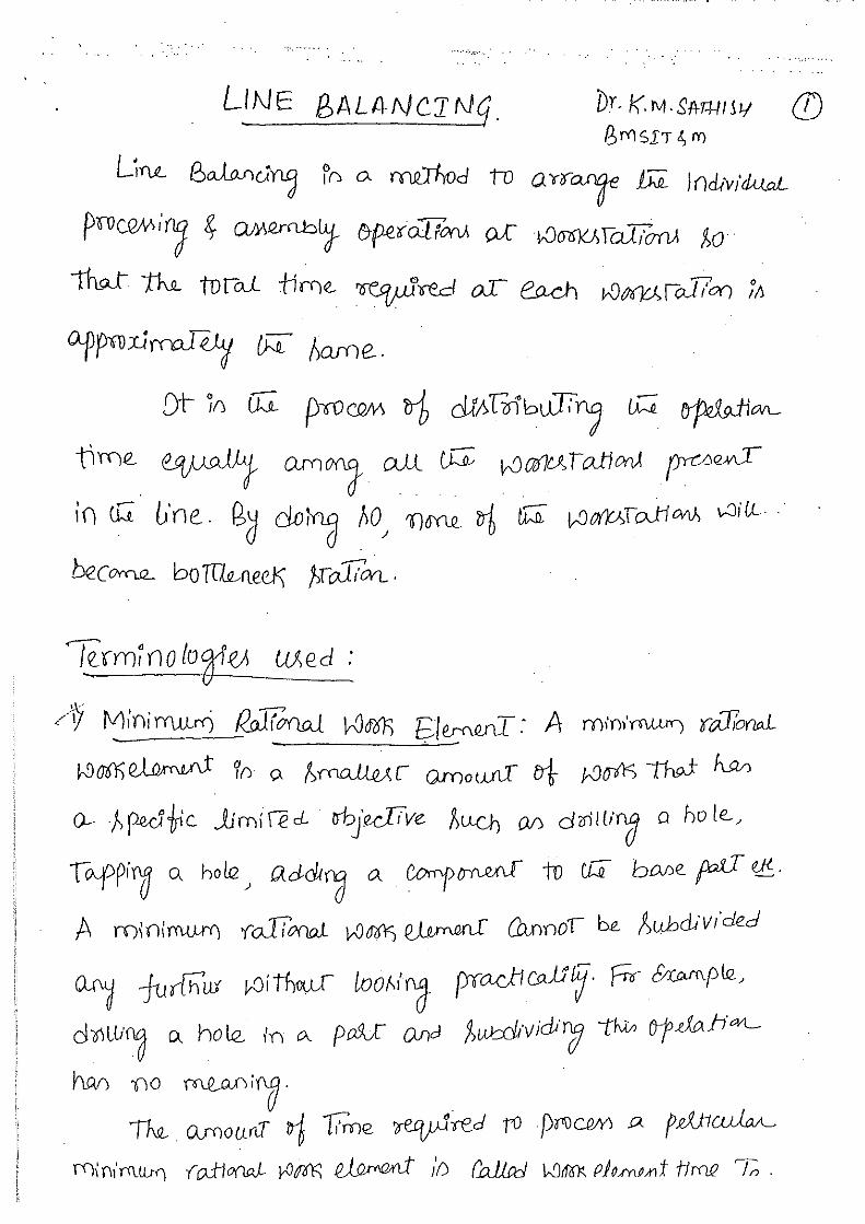
5. Line Balancing
6. Computer Numerical Control
7. Robot Technology
8. Additive Manufacturing Systems
9. Future of Automated Factory
Computer Integrated Manufacturing VI Semester
Dr. K. M. Sathish Kumar, Dept. of ME, BMSIT&M
Chapter 1
Introduction to CIM and Automation
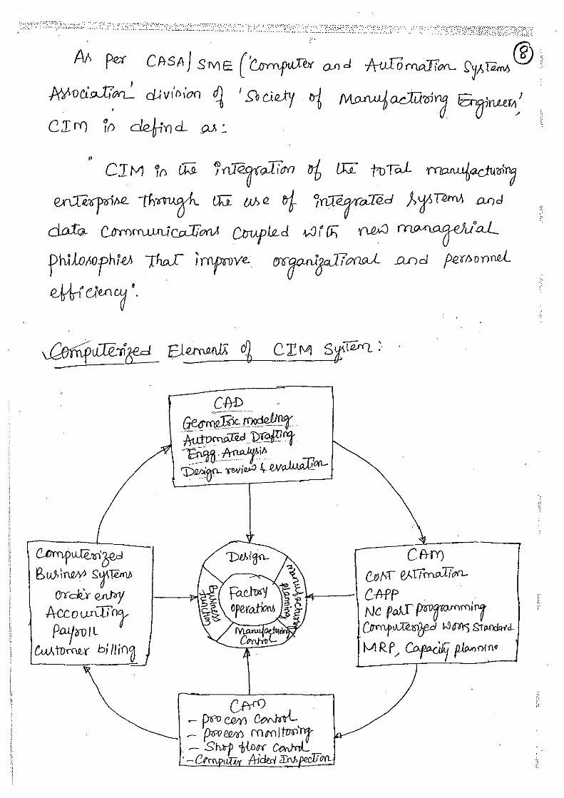
Computer Integrated Manufacturing (CIM) encompasses the entire range of product development and
manufacturing activities with all the functions being carried out with the help of dedicated software
packages. The data required for various functions are passed from one application software to another
in a seamless manner. For example, the product data is created during design. This data has to be
transferred from the modeling software to manufacturing software without any loss of data. CIM uses
a common database wherever feasible and communication technologies to integrate design,
manufacturing and associated business functions that combine the automated segments of a factory
or a manufacturing facility. CIM reduces the human component of manufacturing and thereby relieves
the process of its slow, expensive and error-prone component. CIM stands for a holistic and
methodological approach to the activities of the manufacturing enterprise in order to achieve vast
improvement in its performance.
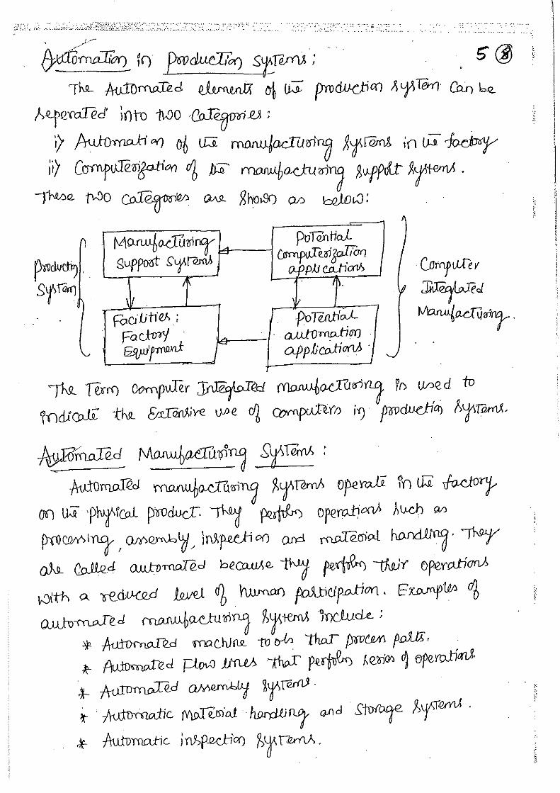
Automation is a dynamic technology that represents a continuous evolutionary process. It is the
process of reducing the human labour by an automated machines.
Automation is a technology concerned with the application of Mechanical, Electrical, Electronic,
Computer, Hydraulic and Pneumatic based system to operate and control production.
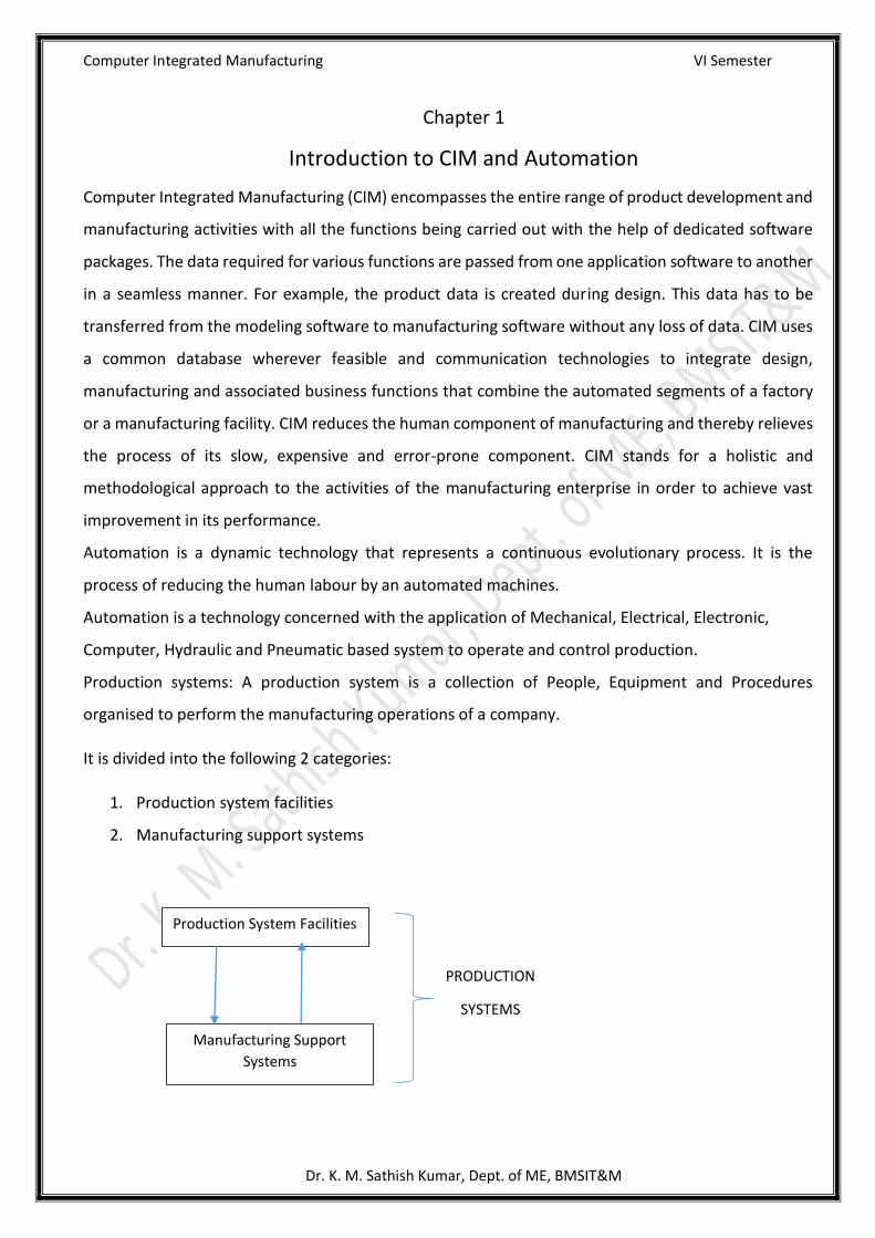
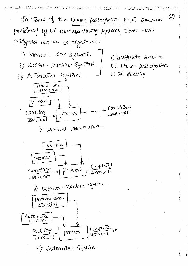
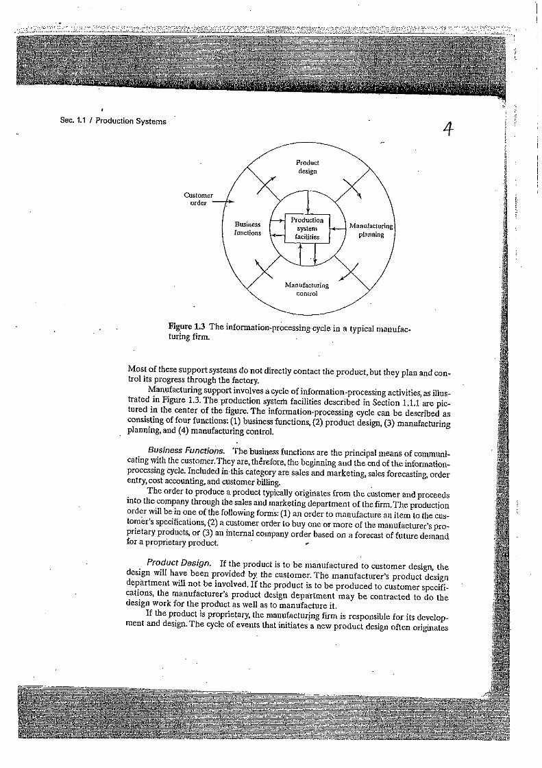
Production systems: A production system is a collection of People, Equipment and Procedures
organised to perform the manufacturing operations of a company.
It is divided into the following 2 categories:
1. Production system facilities
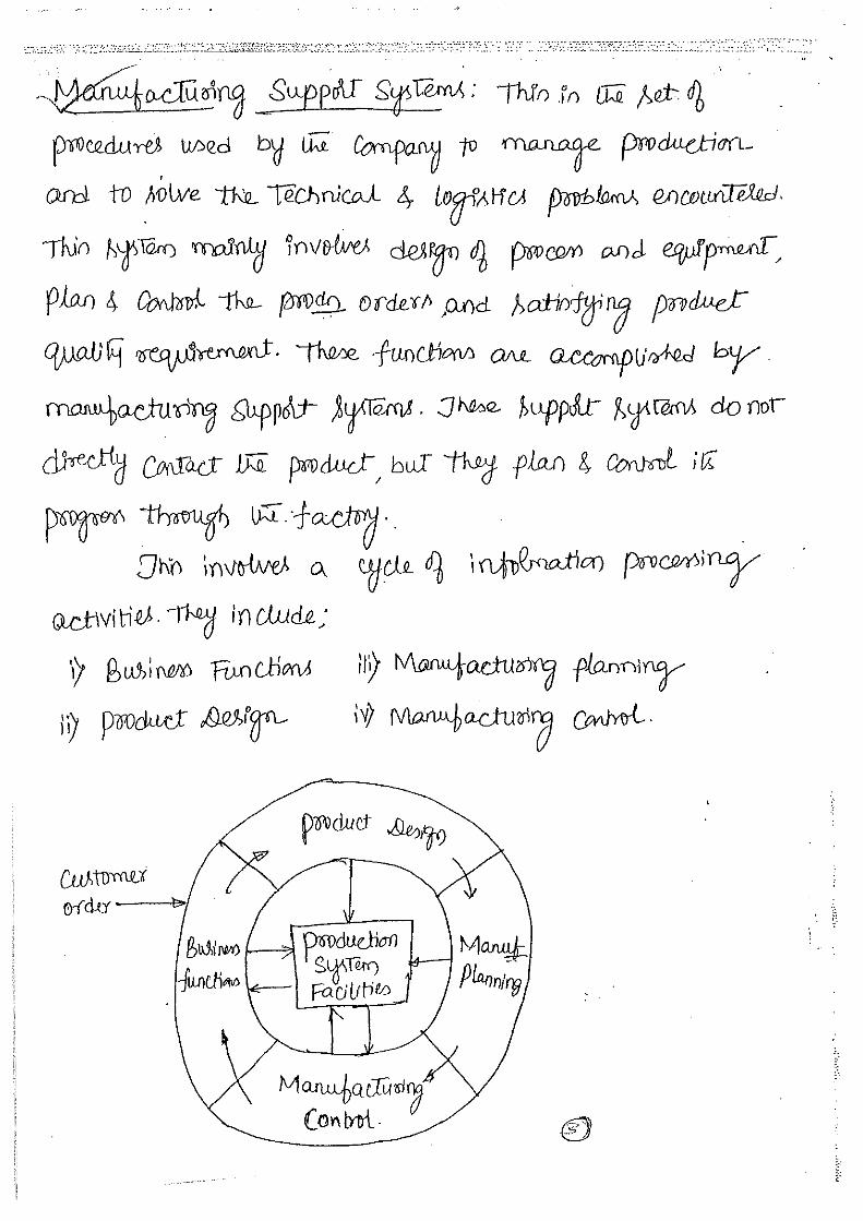
2. Manufacturing support systems
PRODUCTION
SYSTEMS
Production System Facilities
Manufacturing Support
Systems


Computer Integrated Manufacturing 17ME62 Module 2
Dr. K. M. Sathish Kumar, Dept. of ME, BMSIT&M
Computerized Manufacture Planning and Control System
**This study material is in addition to the pdf material (PART I) which was shared**
Dr. K. M. Sathish Kumar Professor and Head, Dept. of ME, BMSIT&M
Production Planning and Control Systems:
Production planning and control (PPC) is concerned with the logistics problems that are
encountered in manufacturing, that is, managing the details of what and how many
products to produce and when, and obtaining the raw materials, parts, and resources to
produce those products. PPC solves these logistics problems by managing information.
Computers are essential for processing the tremendous amounts of data involved to define
the products and the means to produce them, and for reconciling these technical details
with the desired production schedule. In a very real sense, PPC is the integrator in
computer-integrated manufacturing.
Production planning consists of:
1. Deciding which products to make, in what quantities, and when they should be
completed
2. Scheduling the delivery and/or production of the parts and products
3. Planning the manpower and equipment resources needed to accomplish the
production plan.
Production control consists of determining whether the necessary resources to implement
the production plan have been provided, and if not, attempting to take corrective action to
address the deficiencies. As its name suggests, production control includes various
systems and techniques for controlling production and inventory in the factory.
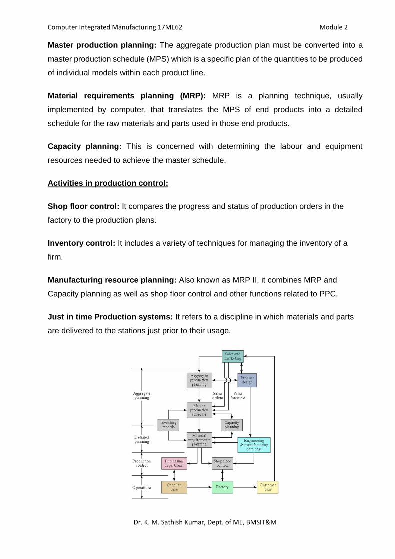
Typical activities of PPC System:
Activities in production planning:
Aggregate production planning: This involves planning the production output levels for
major product lines produced by the firm. These plans must be coordinated among various
functions in the firm, including product design, production, marketing, and sales.
Computer Integrated Manufacturing 17ME62 Module 2
Dr. K. M. Sathish Kumar, Dept. of ME, BMSIT&M
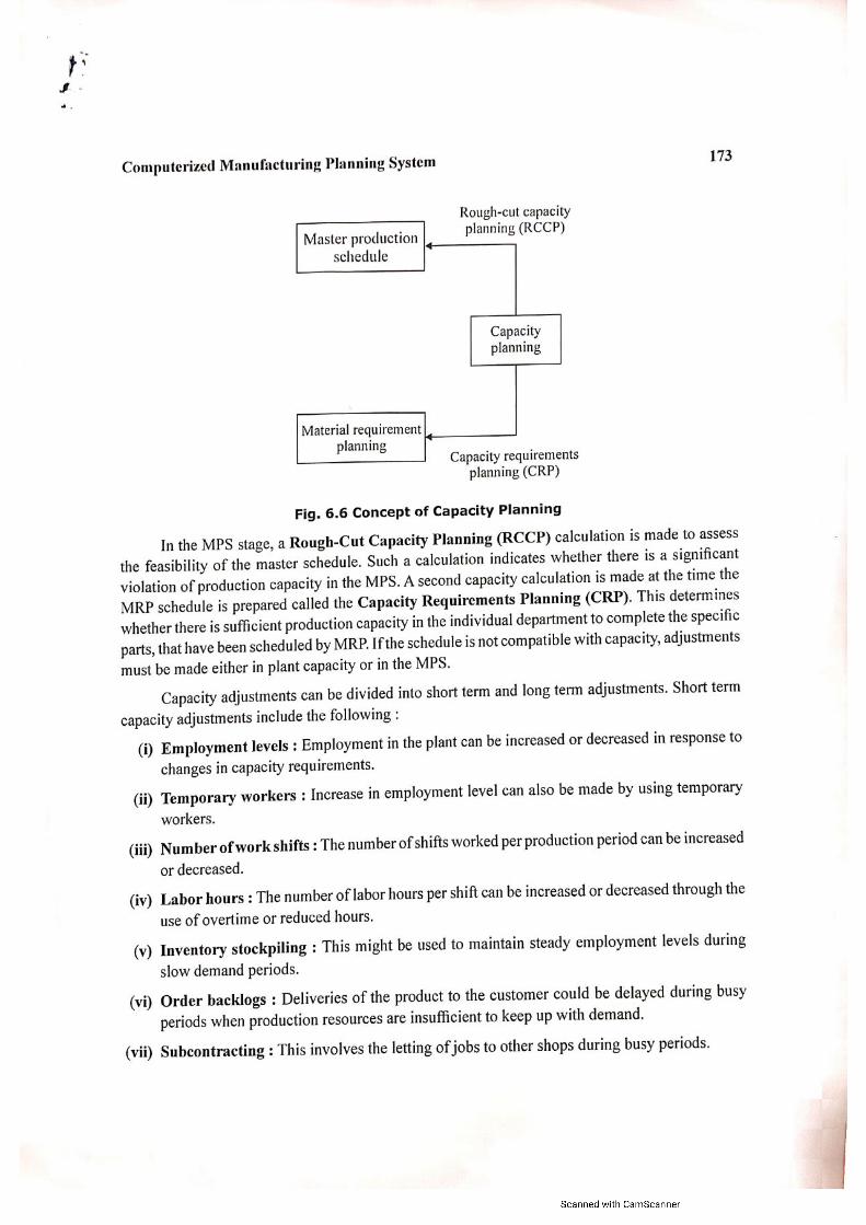
Master production planning: The aggregate production plan must be converted into a
master production schedule (MPS) which is a specific plan of the quantities to be produced
of individual models within each product line.
Material requirements planning (MRP): MRP is a planning technique, usually
implemented by computer, that translates the MPS of end products into a detailed
schedule for the raw materials and parts used in those end products.
Capacity planning: This is concerned with determining the labour and equipment
resources needed to achieve the master schedule.
Activities in production control:
Shop floor control: It compares the progress and status of production orders in the
factory to the production plans.
Inventory control: It includes a variety of techniques for managing the inventory of a
firm.
Manufacturing resource planning: Also known as MRP II, it combines MRP and
Capacity planning as well as shop floor control and other functions related to PPC.
Just in time Production systems: It refers to a discipline in which materials and parts
are delivered to the stations just prior to their usage.
Computer Integrated Manufacturing 17ME62 Module 2
Dr. K. M. Sathish Kumar, Dept. of ME, BMSIT&M
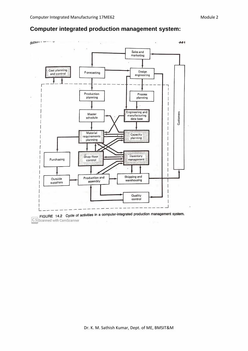
Computer integrated production management system:
Computer Integrated Manufacturing 17ME62 Module 2
Dr. K. M. Sathish Kumar, Dept. of ME, BMSIT&M
Shop floor control:
Shop floor control (SFC) is the set of activities in production control that are concerned
with releasing production orders to the factory, monitoring and controlling the progress of
the orders through the various work centers, and acquiring current information on the
status of the orders.
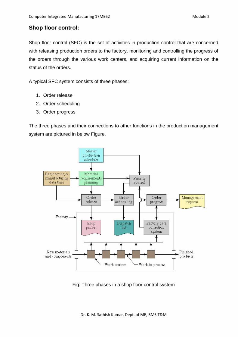
A typical SFC system consists of three phases:
1. Order release
2. Order scheduling
3. Order progress
The three phases and their connections to other functions in the production management
system are pictured in below Figure.
Fig: Three phases in a shop floor control system
Computer Integrated Manufacturing 17ME62 Module 2
Dr. K. M. Sathish Kumar, Dept. of ME, BMSIT&M
In modern implementations of shop floor control, these phases are executed by a
combination of computer and human resources, with a growing proportion accomplished
by computer automated methods.
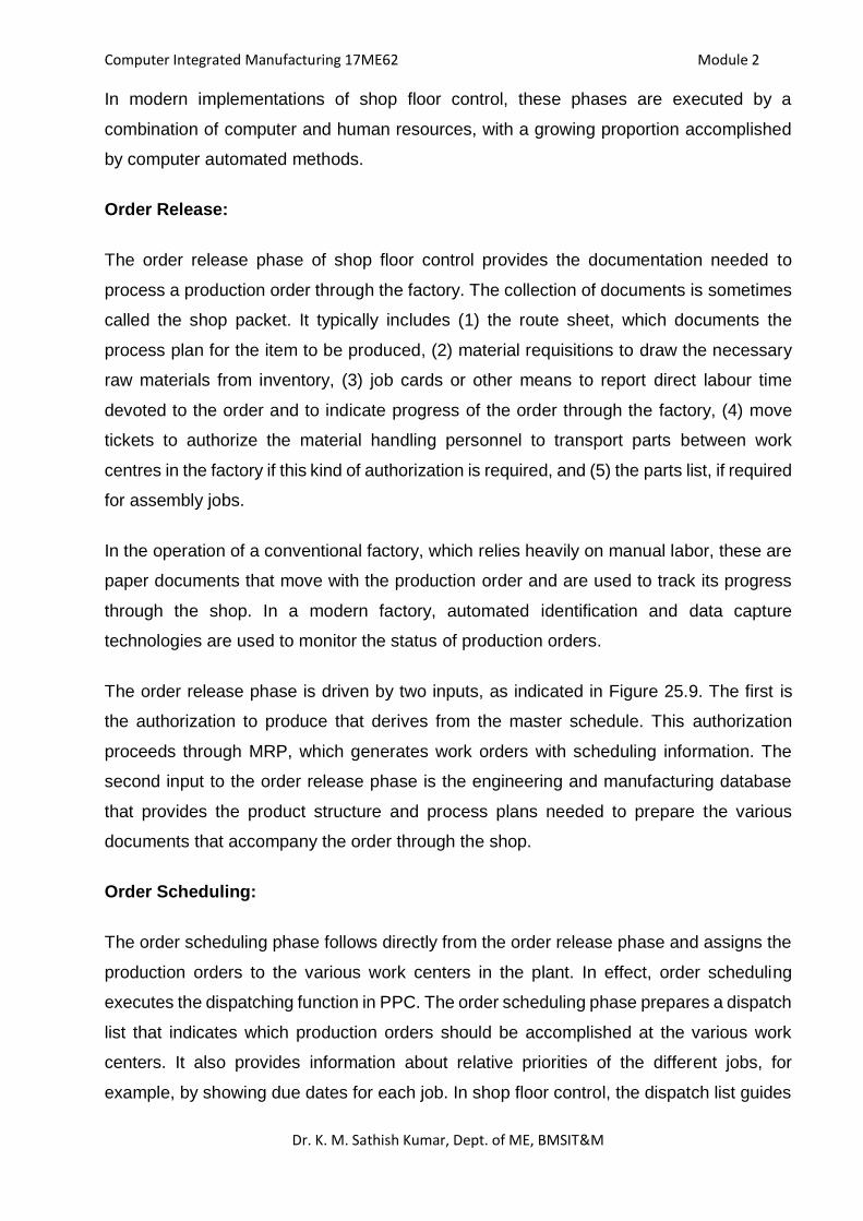
Order Release:
The order release phase of shop floor control provides the documentation needed to
process a production order through the factory. The collection of documents is sometimes
called the shop packet. It typically includes (1) the route sheet, which documents the
process plan for the item to be produced, (2) material requisitions to draw the necessary
raw materials from inventory, (3) job cards or other means to report direct labour time
devoted to the order and to indicate progress of the order through the factory, (4) move
tickets to authorize the material handling personnel to transport parts between work
centres in the factory if this kind of authorization is required, and (5) the parts list, if required
for assembly jobs.
In the operation of a conventional factory, which relies heavily on manual labor, these are
paper documents that move with the production order and are used to track its progress
through the shop. In a modern factory, automated identification and data capture
technologies are used to monitor the status of production orders.
The order release phase is driven by two inputs, as indicated in Figure 25.9. The first is
the authorization to produce that derives from the master schedule. This authorization
proceeds through MRP, which generates work orders with scheduling information. The
second input to the order release phase is the engineering and manufacturing database
that provides the product structure and process plans needed to prepare the various
documents that accompany the order through the shop.
Order Scheduling:
The order scheduling phase follows directly from the order release phase and assigns the
production orders to the various work centers in the plant. In effect, order scheduling
executes the dispatching function in PPC. The order scheduling phase prepares a dispatch
list that indicates which production orders should be accomplished at the various work
centers. It also provides information about relative priorities of the different jobs, for
example, by showing due dates for each job. In shop floor control, the dispatch list guides
Computer Integrated Manufacturing 17ME62 Module 2
Dr. K. M. Sathish Kumar, Dept. of ME, BMSIT&M
the shop foreman in making work assignments and allocating resources to different jobs
to comply with the master schedule.
The order scheduling phase in shop floor control is intended to solve two problems in
production control: (1) Machine loading and (2) Job sequencing.
To schedule a given set of production orders or jobs in the factory, the orders must first be
assigned to work centers. Allocating orders to work centers is referred to as machine
loading. The term shop loading is also used, which refers to the loading of all machines in
the plant. Since the total number of production orders usually exceeds the number of work
centers, each work center will have a queue of orders waiting to be processed. The
remaining question is: In what sequence should these jobs be processed? Answering this
question is the problem in job sequencing, which involves determining the sequence in
which the jobs will be processed through a given work center. To determine this sequence,
priorities are established among the jobs in the queue, and the jobs are processed in the
order of their relative priorities. Priority control is a term used in production control to denote
the function that maintains the appropriate priority levels for the various production orders
in the shop.
Order Progress:
The order progress phase in shop floor control monitors the status of the various orders in
the plant, work-in-process, and other measures that indicate the progress of production.
The function of the order progress phase is to provide information that is useful in
managing the factory. The information presented to production management is often
summarized in the form of reports, such as the following:
Work order status reports: These reports indicate the status of production orders. Typical
information in the report includes the current work center where each order is located,
processing hours remaining before completion of each order, whether each job is on time
or behind schedule, and the priority level of each order.
Progress reports: A progress report is used to report performance of the shop during a
certain time period (e.g., a week or month in the master schedule). It provides information
on how many orders were completed during the period, how many orders should have
been completed during the period but were not, and so forth.
Computer Integrated Manufacturing 17ME62 Module 2
Dr. K. M. Sathish Kumar, Dept. of ME, BMSIT&M
Exception reports: An exception report identifies deviations from the production schedule
(e.g., overdue jobs) and similar nonconformities. These reports are useful to production
management in making decisions about allocation of resources, authorization of overtime
hours, and other capacity issues, and in identifying problem areas in the plant that
adversely affect achieving the master production schedule.
Computer Aided Quality Control (CAQC):
Quality in manufacturing context can be defined as the degree to which a product or its
components conform to certain standards that have been specified by the designer. The
design standard generally relates to the materials, dimensions and tolerances,
appearance, performance, reliability, and any other measurable characteristics of the
product.
The use of the computers for quality control of the product is called as the Computer
Aided Quality Control or CAQC.
The two major parts of quality control are inspection and testing, which are traditionally
performed manually with the help of gages, measuring devices and the testing apparatus.
Inspection is normally used to examine whether a product conforms to the design
standards specified for it. For a mechanical component, this would be probably concerned
with the dimensions, surface texture and tolerances specified for the part. Non-conforming
goods result in scrap, rework, and the loss of customer goodwill.
The common situations that warrant inspection are:
Incoming materials (raw materials, standard items, subcontracted parts)
Stage inspection during manufacturing (e.g., when the parts are moved from one
production section to another)
At the completion of processing of the parts
Before shipping the final assembled product to the customer.
Testing is a significant stage of work in product development to prove the capability of the
product. Testing is normally associated with the functional aspect of item, and is often
directed at the final product rather than its components. Testing consists of the appraisal
Computer Integrated Manufacturing 17ME62 Module 2
Dr. K. M. Sathish Kumar, Dept. of ME, BMSIT&M
of the performance of the final product under actual or simulated conditions. If the product
successfully passes the tests, it is deemed suitable for use. Testing ascertains the quality
of performance of the product.
Various categories of tests used for final product evaluation are listed below:
Functional tests under normal or simulated operating conditions
Fatigue or wear tests to determine the product’s life function until failure
Overload tests to determine the level of safety factor built into the product
Environmental testing to determine how well the product will perform under different
environments (e.g. humidity, temperature, vibration).
Role of Computers in Quality Control (QC):
The two major parts of computer aided quality control are computer aided inspection (CAI)
and computer aided testing (CAT). CAI and CAT are performed by using the latest
computer automation and sensor technology. CAI and CAT are the standalone systems
and without them the full potential of CAQC cannot be achieved.
OBJECTIVES OF CAQC:
The objectives of Computer-Aided Quality Control are to:
i. Improve product quality
ii. Increase productivity in the inspection process
iii. Increase productivity
iv. Reduce lead-time
v. Reduce wastage due to scrap/rework
The strategy for achieving these objectives is basically to automate the inspection process
through the application of computers combined with sensor technology. Where technically
possible and economically feasible, inspection should be done on a 100% basis rather
sampling.
Computer Integrated Manufacturing 17ME62 Module 2
Dr. K. M. Sathish Kumar, Dept. of ME, BMSIT&M
Advantages of CAQC:
100% testing and inspection: With Computer aided inspection and computer
aided testing, inspection and testing will typically be done on a 100% basis rather
by the sampling procedures normally used in traditional QC. This eliminates any
problem in assembly later and therefore is important in CIM.
Inspection is integrated into the manufacturing process. This will help to reduce the
lead-time to complete the parts.
An important feature of QC in a CIM environment is that the CAD/CAM database
will be used to develop inspection plan.
The use of non-contact sensors is recommended for computer aided inspection and
CIM. With contact inspection devices, the part must be stopped and often
repositioned to allow the inspection device to be applied properly. These activities
take time. With non-contact sensing devices, the parts can be inspected while in
operation. The inspection can thus be completed in a fraction of a second.
Computerized feedback control system: The data collected by the non-contact
sensors is sent as the feedback to the computerized control systems. These
systems would carry out the analysis of the data including statistical trend analysis.
This helps in identifying the problem going on in the manufacturing line and find
appropriate solution to it.
Inspection: Inspection refers to the activity of examining the product, its components,
subassemblies to determine whether they conform to the design specifications. Classified
as
1. Inspection for variables: In which one or more quality characteristics of interest are
measured using an appropriate measuring instrument or sensor.
2. Inspection for attributes: In which the part or product is inspected to determine
whether it conforms to the accepted quality standard. The determination is
sometimes based simply on the judgment of the inspector. Inspection by attributes
can also involve counting the number of defects in a product.
Computer Integrated Manufacturing 17ME62 Module 2
Dr. K. M. Sathish Kumar, Dept. of ME, BMSIT&M
Inspection Procedure: A typical inspection procedure performed on an individual item,
such as a part, subassembly, or final product, consists of the following steps
1. Presentation: The item is presented for examination.
2. Examination: The item is examined for one or more nonconforming features. In
inspection for variables, examination consists of measuring a dimension or other
attribute of the part or product. In inspection for attributes, it involves gaging one or
more dimensions or searching the item for flaws.
3. Decision: Based on the examination, a decision is made whether the item satisfies
the defined quality standards. The simplest case involves a binary decision, in which
the item is deemed either acceptable or unacceptable. In more complicated cases,
the decision may involve grading the item into one of more than two possible quality
categories, such as grade A, grade B, and unacceptable.
4. Action: The decision should result in some action, such as accepting or rejecting
the item, or sorting the item into the most appropriate quality grade. It may also be
desirable to take action to correct the manufacturing process to minimize the future
occurrence of defects.
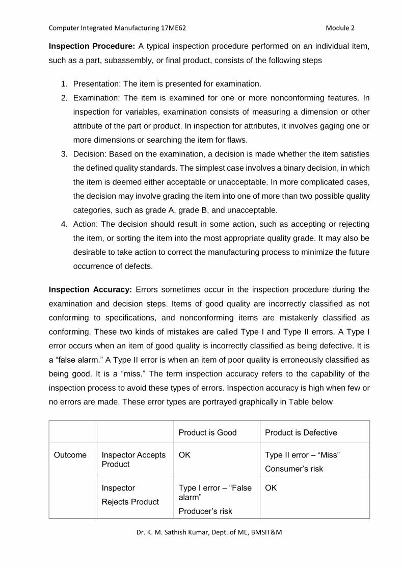
Inspection Accuracy: Errors sometimes occur in the inspection procedure during the
examination and decision steps. Items of good quality are incorrectly classified as not
conforming to specifications, and nonconforming items are mistakenly classified as
conforming. These two kinds of mistakes are called Type I and Type II errors. A Type I
error occurs when an item of good quality is incorrectly classified as being defective. It is
a “false alarm.” A Type II error is when an item of poor quality is erroneously classified as
being good. It is a “miss.” The term inspection accuracy refers to the capability of the
inspection process to avoid these types of errors. Inspection accuracy is high when few or
no errors are made. These error types are portrayed graphically in Table below
Product is Good Product is Defective
Outcome Inspector Accepts Product
OK Type II error – “Miss”
Consumer’s risk
Inspector
Rejects Product
Type I error – “False alarm”
Producer’s risk
OK
Computer Integrated Manufacturing 17ME62 Module 2
Dr. K. M. Sathish Kumar, Dept. of ME, BMSIT&M
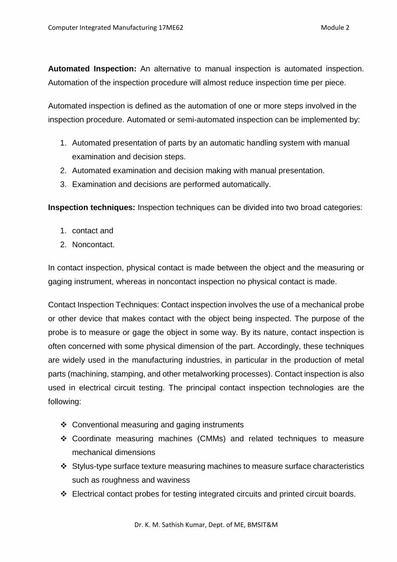
Automated Inspection: An alternative to manual inspection is automated inspection.
Automation of the inspection procedure will almost reduce inspection time per piece.
Automated inspection is defined as the automation of one or more steps involved in the
inspection procedure. Automated or semi-automated inspection can be implemented by:
1. Automated presentation of parts by an automatic handling system with manual
examination and decision steps.
2. Automated examination and decision making with manual presentation.
3. Examination and decisions are performed automatically.
Inspection techniques: Inspection techniques can be divided into two broad categories:
1. contact and
2. Noncontact.
In contact inspection, physical contact is made between the object and the measuring or
gaging instrument, whereas in noncontact inspection no physical contact is made.
Contact Inspection Techniques: Contact inspection involves the use of a mechanical probe
or other device that makes contact with the object being inspected. The purpose of the
probe is to measure or gage the object in some way. By its nature, contact inspection is
often concerned with some physical dimension of the part. Accordingly, these techniques
are widely used in the manufacturing industries, in particular in the production of metal
parts (machining, stamping, and other metalworking processes). Contact inspection is also
used in electrical circuit testing. The principal contact inspection technologies are the
following:
Conventional measuring and gaging instruments
Coordinate measuring machines (CMMs) and related techniques to measure
mechanical dimensions
Stylus-type surface texture measuring machines to measure surface characteristics
such as roughness and waviness
Electrical contact probes for testing integrated circuits and printed circuit boards.
Computer Integrated Manufacturing 17ME62 Module 2
Dr. K. M. Sathish Kumar, Dept. of ME, BMSIT&M
Noncontact Inspection Technologies: Noncontact inspection methods utilize a sensor
located at a certain distance from the object to measure or gage the desired features. The
noncontact inspection technologies can be classified into two categories: optical and
nonoptical. Optical inspection technologies use light to accomplish the measurement or
gaging cycle. The most important optical technology is machine vision; Nonoptical
inspection technologies utilize energy forms other than light to perform the inspection;
these other energies include various electrical fields, radiation (other than light), and
ultrasonics.
Noncontact inspection offers certain advantages over contact inspection, including the
following:
They avoid damage to the part surface that might result from contact inspection.
Inspection cycle times are inherently faster. Contact inspection procedures require
the contacting probe to be positioned against the part, which takes time. Most of the
noncontact methods use a stationary probe that does not need repositioning for
each part.
Noncontact methods can often be accomplished on the production line without the
need for any additional handling of the parts, whereas contact inspection usually
requires special handling and positioning of the parts.
It is more feasible to conduct 100% automated inspection, since noncontact
methods have faster cycle times and reduced need for special handling.
Coordinate Measuring Machines:
Coordinate metrology is concerned with measuring the actual shape and dimensions of an
object and comparing these results with the desired shape and dimensions, as might be
specified on a part drawing. In this sense, coordinate metrology consists of the evaluation
of the location, orientation, dimensions, and geometry of the part or object.
A coordinate measuring machine (CMM) is an electromechanical system designed to
perform coordinate metrology. It has a contact probe that can be positioned in three
dimensions relative to the surfaces of a work part. The x, y, and z coordinates of the probe
can be accurately and precisely recorded to obtain dimensional data about the part
geometry.
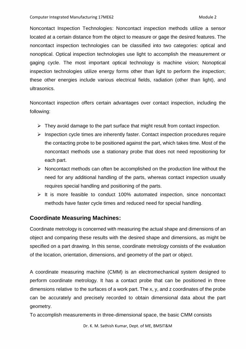
To accomplish measurements in three-dimensional space, the basic CMM consists
Computer Integrated Manufacturing 17ME62 Module 2
Dr. K. M. Sathish Kumar, Dept. of ME, BMSIT&M
of the following components:
Probe head and probe to contact the work part surfaces
Mechanical structure that provides motion of the probe in three Cartesian axes and
displacement transducers to measure the coordinate values of each axis.
In addition, many CMMs include the following:
Drive system and control unit to move each of the three axes
Digital computer system with application software.
Coordinate Measuring Machine (CMM)
Computer Integrated Manufacturing 17ME62 Module 2
Dr. K. M. Sathish Kumar, Dept. of ME, BMSIT&M
CMM Construction: In the construction of a CMM, the probe is fastened to a mechanical
structure that allows movement of the probe relative to the part. The part is usually located
on a worktable that is connected to the structure. The two basic components of the CMM
are its probe and its mechanical structure.
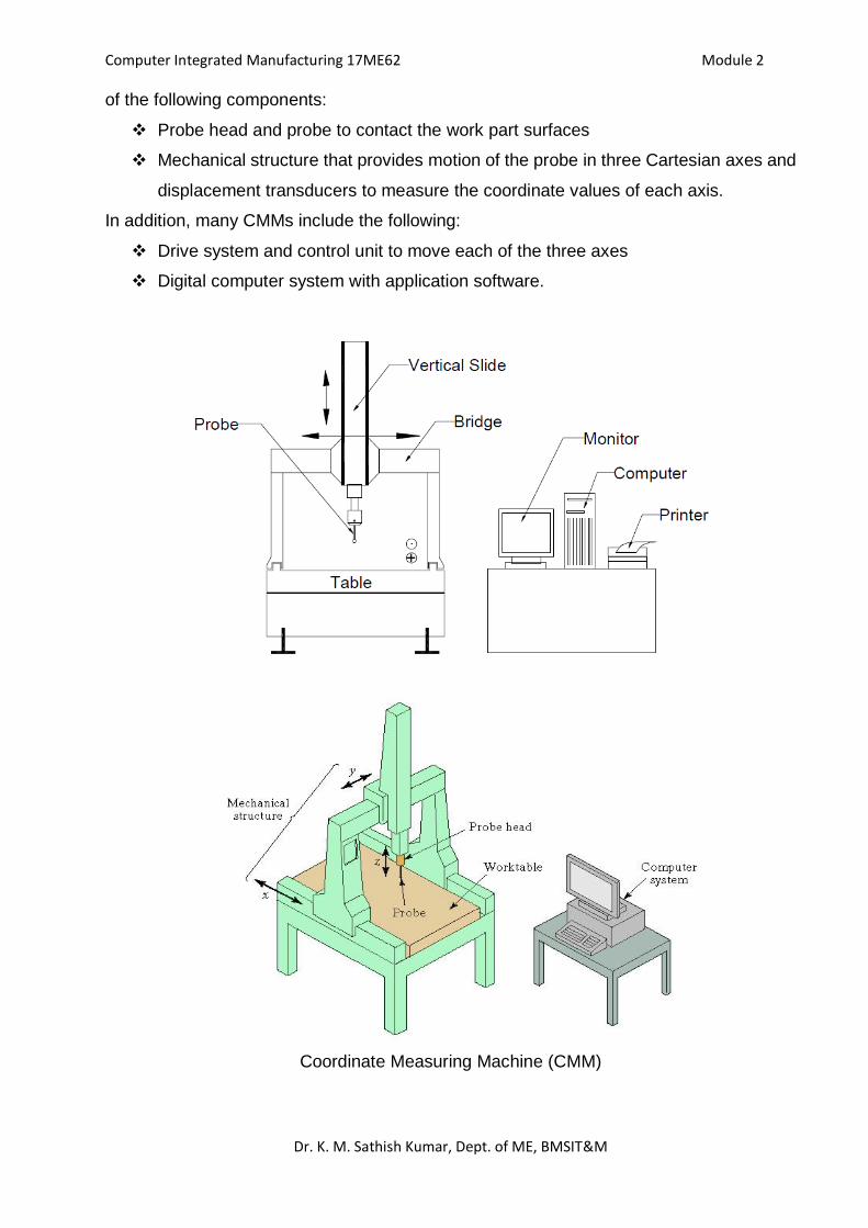
Probe: The contact probe indicates when contact has been made with the part surface
during measurement. The tip of the probe is usually a ruby ball. Ruby is a form of corundum
(aluminum oxide), whose desirable properties in this application include high hardness for
wear resistance and low density for minimum inertia. Probes can have either a single tip,
as in Fig (a) or multiple tips as in Fig (b).
Fig (a) Single tip Fig (b) Multiple tip
Most probes today are touch-trigger probes, which actuate when the probe makes contact
with the part surface. Commercially available touch-trigger probes utilize any of various
triggering mechanisms, including the following:
(1) A highly sensitive electrical contact switch that emits a signal when the tip of the probe
is deflected from its neutral position
(2) A contact switch that permits actuation only when electrical contact is established
between the probe and the (metallic) part surface
(3) A piezoelectric sensor that generates a signal based on tension or compression loading
of the probe.
Computer Integrated Manufacturing 17ME62 Module 2
Dr. K. M. Sathish Kumar, Dept. of ME, BMSIT&M
Immediately after contact is made between the probe and the surface of the object, the
coordinate positions of the probe are accurately measured by displacement transducers
associated with each of the three linear axes and recorded by the CMM controller. After
the probe has been separated from the contact surface, it returns to its neutral position.
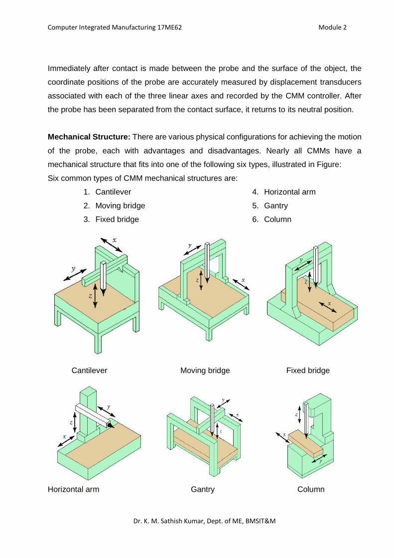
Mechanical Structure: There are various physical configurations for achieving the motion
of the probe, each with advantages and disadvantages. Nearly all CMMs have a
mechanical structure that fits into one of the following six types, illustrated in Figure:
Six common types of CMM mechanical structures are:
1. Cantilever
2. Moving bridge
3. Fixed bridge
4. Horizontal arm
5. Gantry
6. Column
Cantilever Moving bridge Fixed bridge
Horizontal arm Gantry Column
Computer Integrated Manufacturing 17ME62 Module 2
Dr. K. M. Sathish Kumar, Dept. of ME, BMSIT&M
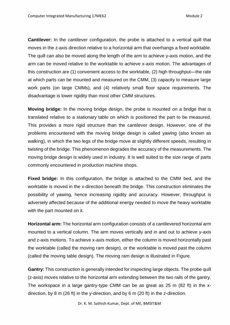
Cantilever: In the cantilever configuration, the probe is attached to a vertical quill that
moves in the z-axis direction relative to a horizontal arm that overhangs a fixed worktable.
The quill can also be moved along the length of the arm to achieve y-axis motion, and the
arm can be moved relative to the worktable to achieve x-axis motion. The advantages of
this construction are (1) convenient access to the worktable, (2) high throughput—the rate
at which parts can be mounted and measured on the CMM, (3) capacity to measure large
work parts (on large CMMs), and (4) relatively small floor space requirements. The
disadvantage is lower rigidity than most other CMM structures.
Moving bridge: In the moving bridge design, the probe is mounted on a bridge that is
translated relative to a stationary table on which is positioned the part to be measured.
This provides a more rigid structure than the cantilever design. However, one of the
problems encountered with the moving bridge design is called yawing (also known as
walking), in which the two legs of the bridge move at slightly different speeds, resulting in
twisting of the bridge. This phenomenon degrades the accuracy of the measurements. The
moving bridge design is widely used in industry. It is well suited to the size range of parts
commonly encountered in production machine shops.
Fixed bridge: In this configuration, the bridge is attached to the CMM bed, and the
worktable is moved in the x-direction beneath the bridge. This construction eliminates the
possibility of yawing, hence increasing rigidity and accuracy. However, throughput is
adversely affected because of the additional energy needed to move the heavy worktable
with the part mounted on it.
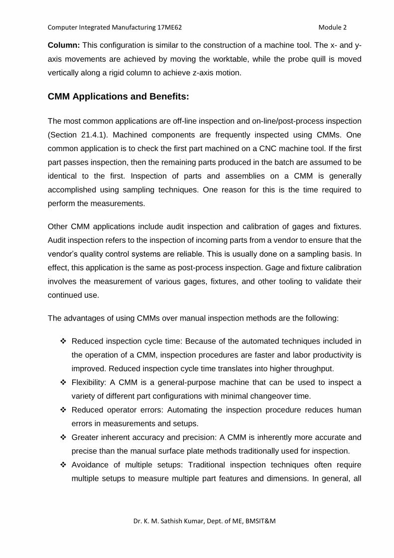
Horizontal arm: The horizontal arm configuration consists of a cantilevered horizontal arm
mounted to a vertical column. The arm moves vertically and in and out to achieve y-axis
and z-axis motions. To achieve x-axis motion, either the column is moved horizontally past
the worktable (called the moving ram design), or the worktable is moved past the column
(called the moving table design). The moving ram design is illustrated in Figure.
Gantry: This construction is generally intended for inspecting large objects. The probe quill
(z-axis) moves relative to the horizontal arm extending between the two rails of the gantry.
The workspace in a large gantry-type CMM can be as great as 25 m (82 ft) in the x-
direction, by 8 m (26 ft) in the y-direction, and by 6 m (20 ft) in the z-direction.
Computer Integrated Manufacturing 17ME62 Module 2
Dr. K. M. Sathish Kumar, Dept. of ME, BMSIT&M
Column: This configuration is similar to the construction of a machine tool. The x- and y-
axis movements are achieved by moving the worktable, while the probe quill is moved
vertically along a rigid column to achieve z-axis motion.
CMM Applications and Benefits:
The most common applications are off-line inspection and on-line/post-process inspection
(Section 21.4.1). Machined components are frequently inspected using CMMs. One
common application is to check the first part machined on a CNC machine tool. If the first
part passes inspection, then the remaining parts produced in the batch are assumed to be
identical to the first. Inspection of parts and assemblies on a CMM is generally
accomplished using sampling techniques. One reason for this is the time required to
perform the measurements.
Other CMM applications include audit inspection and calibration of gages and fixtures.
Audit inspection refers to the inspection of incoming parts from a vendor to ensure that the
vendor’s quality control systems are reliable. This is usually done on a sampling basis. In
effect, this application is the same as post-process inspection. Gage and fixture calibration
involves the measurement of various gages, fixtures, and other tooling to validate their
continued use.
The advantages of using CMMs over manual inspection methods are the following:
Reduced inspection cycle time: Because of the automated techniques included in
the operation of a CMM, inspection procedures are faster and labor productivity is
improved. Reduced inspection cycle time translates into higher throughput.
Flexibility: A CMM is a general-purpose machine that can be used to inspect a
variety of different part configurations with minimal changeover time.
Reduced operator errors: Automating the inspection procedure reduces human
errors in measurements and setups.
Greater inherent accuracy and precision: A CMM is inherently more accurate and
precise than the manual surface plate methods traditionally used for inspection.
Avoidance of multiple setups: Traditional inspection techniques often require
multiple setups to measure multiple part features and dimensions. In general, all
Computer Integrated Manufacturing 17ME62 Module 2
Dr. K. M. Sathish Kumar, Dept. of ME, BMSIT&M
measurements can be made in a single setup on a CMM, thereby increasing
throughput and measurement accuracy.
Machine Vision:
Machine vision consists of the acquisition of image data, followed by the processing and
interpretation of these data by computer for some industrial application. Machine vision is
a growing technology, with its principal applications in automated inspection and robot
guidance. Vision systems are classified as being either 2-D or 3-D.
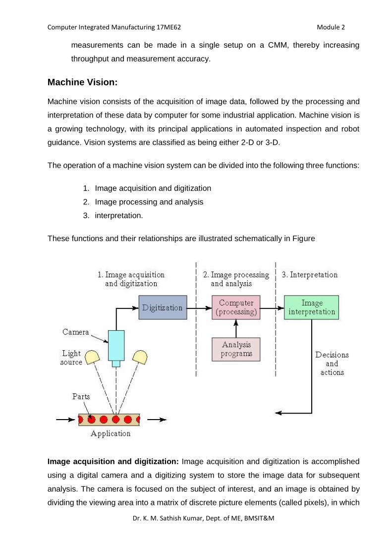
The operation of a machine vision system can be divided into the following three functions:
1. Image acquisition and digitization
2. Image processing and analysis
3. interpretation.
These functions and their relationships are illustrated schematically in Figure
Image acquisition and digitization: Image acquisition and digitization is accomplished
using a digital camera and a digitizing system to store the image data for subsequent
analysis. The camera is focused on the subject of interest, and an image is obtained by
dividing the viewing area into a matrix of discrete picture elements (called pixels), in which
Computer Integrated Manufacturing 17ME62 Module 2
Dr. K. M. Sathish Kumar, Dept. of ME, BMSIT&M
each element has a value that is proportional to the light intensity of that portion of the
scene. The intensity value for each pixel is converted into its equivalent digital value by an
ADC.
Image Processing and Analysis: The second function in the operation of a machine
vision system is image processing and analysis. The amount of data that must be
processed is significant. The data for each frame must be analyzed within the time required
to complete one scan. A number of techniques have been developed for analysing the
image data in a machine vision system. One category of techniques in image processing
and analysis, called segmentation, is intended to define and separate regions of interest
within the image. Two of the common segmentation techniques are thresholding and edge
detection.
Thresholding involves the conversion of each pixel intensity level into a binary value,
representing either white or black. This is done by comparing the intensity value of each
pixel with a defined threshold value. If the pixel value is greater than the threshold, it is
given the binary bit value of white, say 1; if less than the defined threshold, then it is given
the bit value of black, say 0. Reducing the image to binary form by means of thresholding
usually simplifies the subsequent problem of defining and identifying objects in the image.
Edge detection is concerned with determining the location of boundaries between an object
and its surroundings in an image. This is accomplished by identifying the contrast in light
intensity that exists between adjacent pixels at the borders of the object.
Interpretation: For any given application, the image must be interpreted based on the
extracted features. The interpretation function is usually concerned with recognizing the
object, a task called object recognition or pattern recognition. The objective in this task is
to identify the object in the image by comparing it with predefined models or standard
values. Two commonly used interpretation techniques are template matching and feature
weighting. Template matching refers to various methods that attempt to compare one or
more features of an image with the corresponding features of a model or template stored
in computer memory. The most basic template matching technique is one in which the
image is compared, pixel by pixel, with a corresponding computer model. Feature
weighting is a technique in which several features (e.g., area, length, and perimeter) are
combined into a single measure by assigning a weight to each feature according to its
relative importance in identifying the object. The score of the object in the image is
Computer Integrated Manufacturing 17ME62 Module 2
Dr. K. M. Sathish Kumar, Dept. of ME, BMSIT&M
compared with the score of an ideal object residing in computer memory to achieve proper
identification.
Machine Vision Applications: The reason for interpreting the image is to accomplish
some application. Machine vision applications in manufacturing divide into three
categories: (1) inspection, (2) identification, and (3) visual guidance and control.
Inspection: By far, quality control inspection is the biggest category. Machine vision
installations in industry perform a variety of automated inspection tasks, most of which are
either on-line/in-process or on-line/post-process. Typical industrial inspection tasks include
the following:
Dimensional measurement: These applications involve determining the size of
certain dimensional features of parts or products usually moving at relatively high
speeds on a moving conveyor. The machine vision system must compare the
features (dimensions) with the corresponding features of a computer-stored model
and determine the size value.
Dimensional gaging: This is similar to the preceding except that a gaging function
rather than a measurement is performed.
Verification of the presence of components: This is done in an assembled product
such as a printed circuit board assembly.
Verification of hole location and number of holes: Operationally, this task is similar
to dimensional measurement and verification of components.
Detection of surface flaws and defects: Flaws and defects on the surface of a part
or material often reveal themselves as a change in reflected light. The vision system
can identify the deviation from an ideal model of the surface.
Detection of flaws in a printed label: The defect can be in the form of a poorly located
label or poorly printed text, numbering, or graphics on the label.
Part identification applications use a vision system to recognize and perhaps distinguish
parts or other objects so that some action can be taken. The applications include part
sorting, counting different types of parts flowing past along a conveyor, and inventory
monitoring. Part identification can usually be accomplished by 2-D vision systems.
Computer Integrated Manufacturing 17ME62 Module 2
Dr. K. M. Sathish Kumar, Dept. of ME, BMSIT&M
Visual guidance and control involves applications in which a vision system is teamed with
a robot or similar machine to control the movement of the machine. The term vision guided
robotic (VGR) system is used in connection with this technology. Examples of VGR
applications include seam tracking in continuous arc welding, part positioning and/or
reorientation, picking parts from moving conveyors or stationary bins, collision avoidance,
machining operations, and assembly tasks.
***************
1
BMS Institute of Technology and ManagementBengaluru 64
Department of Mechanical Engineering
Course Coordinator
Dr. K.M. Sathish KumarProfessor & Head
Department of Mechanical Engineering
Course Name: Computer Integrated
Manufacturing (17ME62)
FLEXIBLE MANUFACTURING SYSTEMS
(FMS)
(Module 3)
27-08-2020 Dr. K. M. Sathish Kumar, Dept. of
ME, BMSIT&M
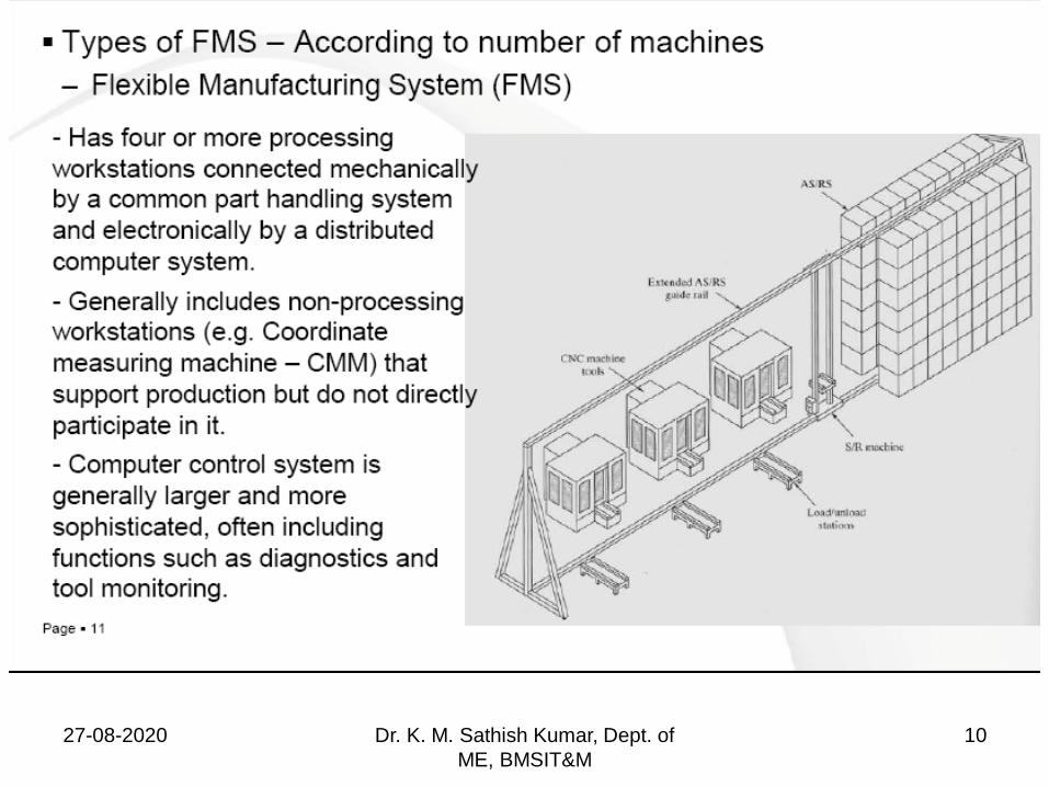
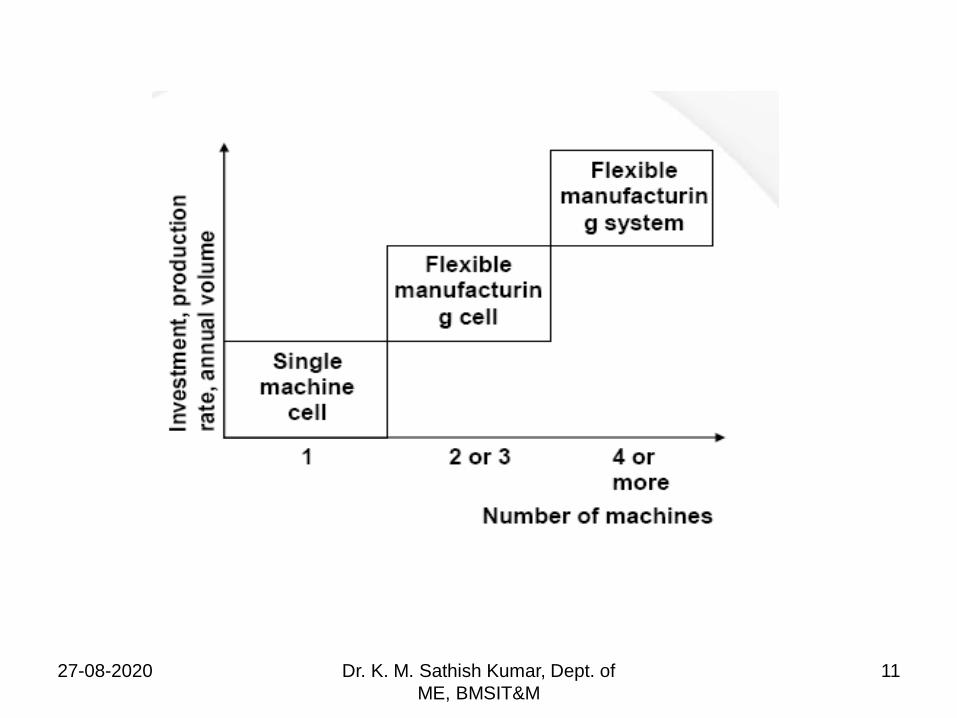
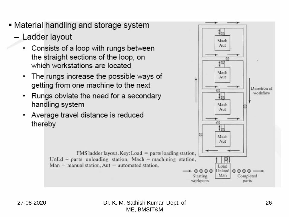
FLEXIBLE MANUFACTURING SYSTEM
“A Flexible Manufacturing System (FMS) consists of a
group of processing stations (usually CNC machine
tools), interconnected by an automated material handling
and storage system and controlled by an integrated
computer system”
FMS is called flexible because it is capable of processing
a variety of different part styles and quantities of
production can be adjusted in response to changing
demand patterns.
It is suited for mid variety and mid volume production
range27-08-2020 Dr. K. M. Sathish Kumar, Dept. of
ME, BMSIT&M
2
27-08-2020 Dr. K. M. Sathish Kumar, Dept. of
ME, BMSIT&M
3
What makes FMS flexible?
27-08-2020 Dr. K. M. Sathish Kumar, Dept. of
ME, BMSIT&M
4
27-08-2020 Dr. K. M. Sathish Kumar, Dept. of
ME, BMSIT&M
5
Types of Flexibility
Machine flexibility
Production flexibility
Mix flexibility
Product flexibility
Routing flexibility
Volume flexibility
Expansion flexibility
27-08-2020 Dr. K. M. Sathish Kumar, Dept. of
ME, BMSIT&M
6
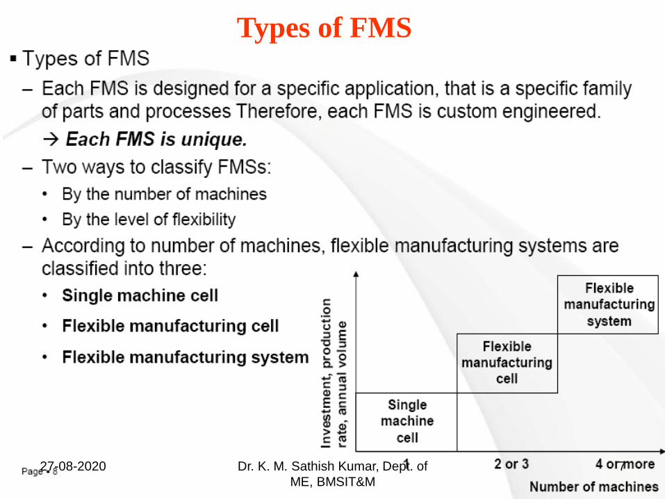
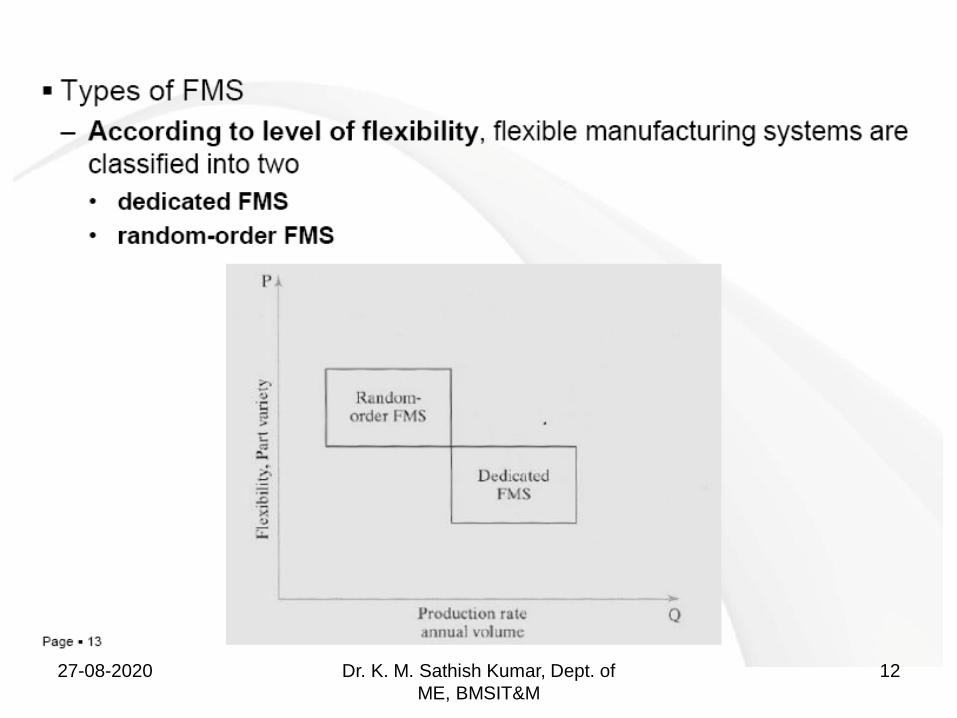
Types of FMS
27-08-2020 Dr. K. M. Sathish Kumar, Dept. of
ME, BMSIT&M
7
27-08-2020 Dr. K. M. Sathish Kumar, Dept. of
ME, BMSIT&M
8
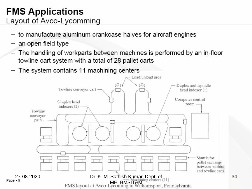
27-08-2020 Dr. K. M. Sathish Kumar, Dept. of
ME, BMSIT&M
9
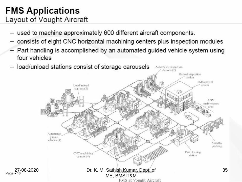
27-08-2020 Dr. K. M. Sathish Kumar, Dept. of
ME, BMSIT&M
10
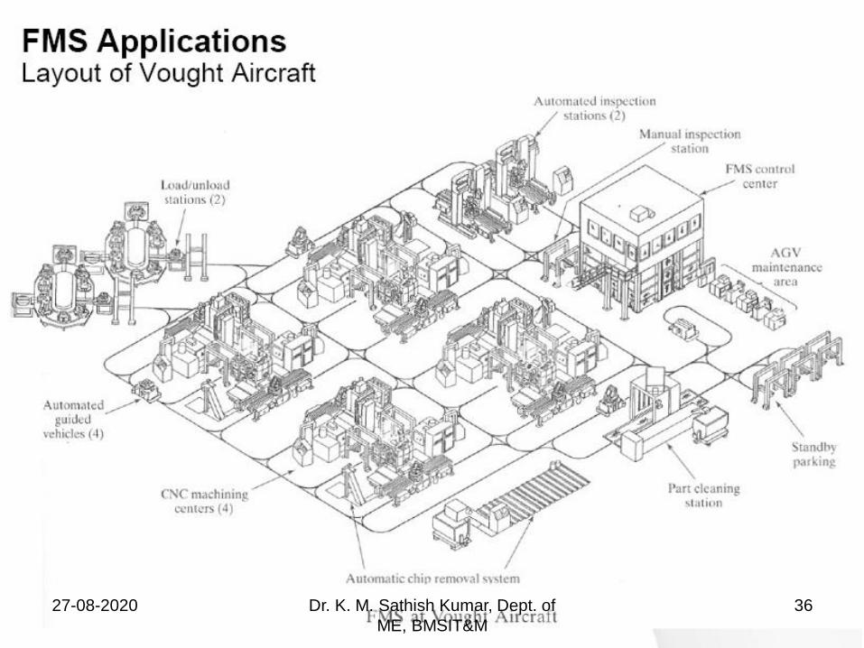
27-08-2020 Dr. K. M. Sathish Kumar, Dept. of
ME, BMSIT&M
11
27-08-2020 Dr. K. M. Sathish Kumar, Dept. of
ME, BMSIT&M
12
27-08-2020 Dr. K. M. Sathish Kumar, Dept. of
ME, BMSIT&M
13
27-08-2020 Dr. K. M. Sathish Kumar, Dept. of
ME, BMSIT&M
14
Components of FMS
27-08-2020 Dr. K. M. Sathish Kumar, Dept. of
ME, BMSIT&M
15
27-08-2020 Dr. K. M. Sathish Kumar, Dept. of
ME, BMSIT&M
16
27-08-2020 Dr. K. M. Sathish Kumar, Dept. of
ME, BMSIT&M
17
27-08-2020 Dr. K. M. Sathish Kumar, Dept. of
ME, BMSIT&M
18
27-08-2020 Dr. K. M. Sathish Kumar, Dept. of
ME, BMSIT&M
19
27-08-2020 Dr. K. M. Sathish Kumar, Dept. of
ME, BMSIT&M
20
27-08-2020 Dr. K. M. Sathish Kumar, Dept. of
ME, BMSIT&M
21
27-08-2020 Dr. K. M. Sathish Kumar, Dept. of
ME, BMSIT&M
22
27-08-2020 Dr. K. M. Sathish Kumar, Dept. of
ME, BMSIT&M
23
27-08-2020 Dr. K. M. Sathish Kumar, Dept. of
ME, BMSIT&M
24
27-08-2020 Dr. K. M. Sathish Kumar, Dept. of
ME, BMSIT&M
25
27-08-2020 Dr. K. M. Sathish Kumar, Dept. of
ME, BMSIT&M
26
27-08-2020 Dr. K. M. Sathish Kumar, Dept. of
ME, BMSIT&M
27
27-08-2020 Dr. K. M. Sathish Kumar, Dept. of
ME, BMSIT&M
28
27-08-2020 Dr. K. M. Sathish Kumar, Dept. of
ME, BMSIT&M
29
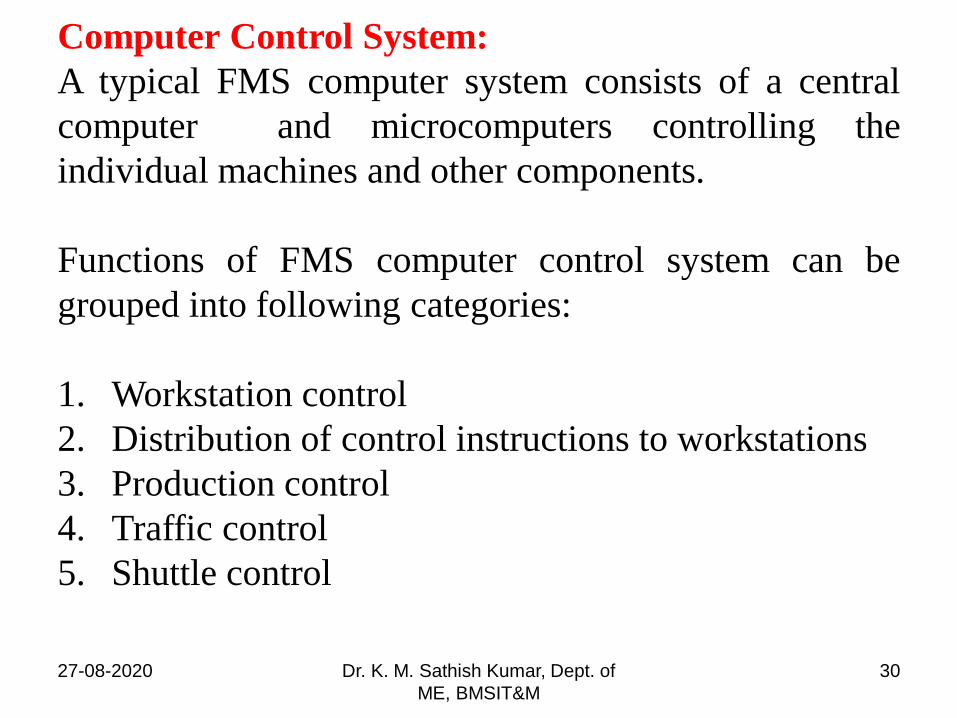
Computer Control System:
A typical FMS computer system consists of a central
computer and microcomputers controlling the
individual machines and other components.
Functions of FMS computer control system can be
grouped into following categories:
1. Workstation control
2. Distribution of control instructions to workstations
3. Production control
4. Traffic control
5. Shuttle control
27-08-2020 Dr. K. M. Sathish Kumar, Dept. of
ME, BMSIT&M
30
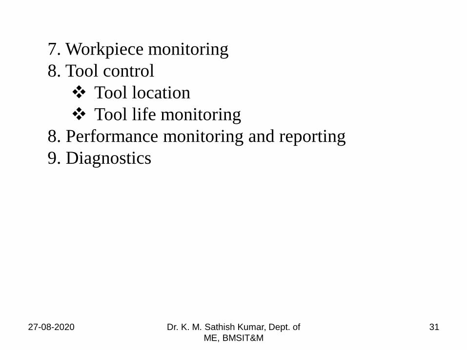
7. Workpiece monitoring
8. Tool control
Tool location
Tool life monitoring
8. Performance monitoring and reporting
9. Diagnostics
27-08-2020 Dr. K. M. Sathish Kumar, Dept. of
ME, BMSIT&M
31
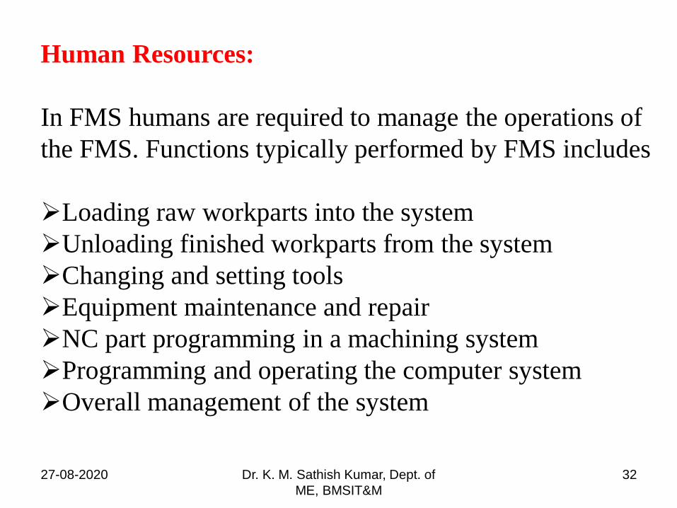
Human Resources:
In FMS humans are required to manage the operations of
the FMS. Functions typically performed by FMS includes
Loading raw workparts into the system
Unloading finished workparts from the system
Changing and setting tools
Equipment maintenance and repair
NC part programming in a machining system
Programming and operating the computer system
Overall management of the system
27-08-2020 Dr. K. M. Sathish Kumar, Dept. of
ME, BMSIT&M
32
27-08-2020 Dr. K. M. Sathish Kumar, Dept. of
ME, BMSIT&M
33
27-08-2020 Dr. K. M. Sathish Kumar, Dept. of
ME, BMSIT&M
34
27-08-2020 Dr. K. M. Sathish Kumar, Dept. of
ME, BMSIT&M
35
27-08-2020 Dr. K. M. Sathish Kumar, Dept. of
ME, BMSIT&M
36
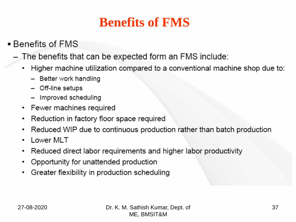
Benefits of FMS
27-08-2020 Dr. K. M. Sathish Kumar, Dept. of
ME, BMSIT&M
37
FMS Planning and Implementation issues
Implementation of FMS represents a major investment
and commitment by the user company. This is divided
into FMS planning & Design issues and FMS operational
issues.
FMS Planning issues
Part family considerations
Processing requirements
Physical characteristics of the workparts
Production volume27-08-2020 Dr. K. M. Sathish Kumar, Dept. of
ME, BMSIT&M
38
FMS Design issues
Types of workstations
Variations in process routings and FMS layout
Material Handling system
Work in process and storage capacity
Tooling
Pallet fixtures
27-08-2020 Dr. K. M. Sathish Kumar, Dept. of
ME, BMSIT&M
39
FMS Operational issues
Scheduling and Dispatching
Machine loading
Part routing
Part grouping
Tool management
Pallet and fixture allocation
27-08-2020 Dr. K. M. Sathish Kumar, Dept. of
ME, BMSIT&M
40
27-08-2020 Dr. K. M. Sathish Kumar, Dept. of
ME, BMSIT&M
41


Computer Integrated Manufacturing 17ME62 Module 4
Dr. K. M. Sathish Kumar, Dept. of ME, BMSIT&M
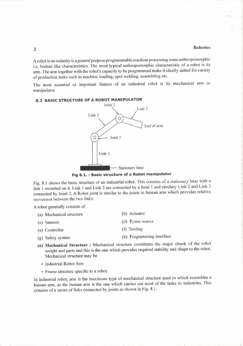
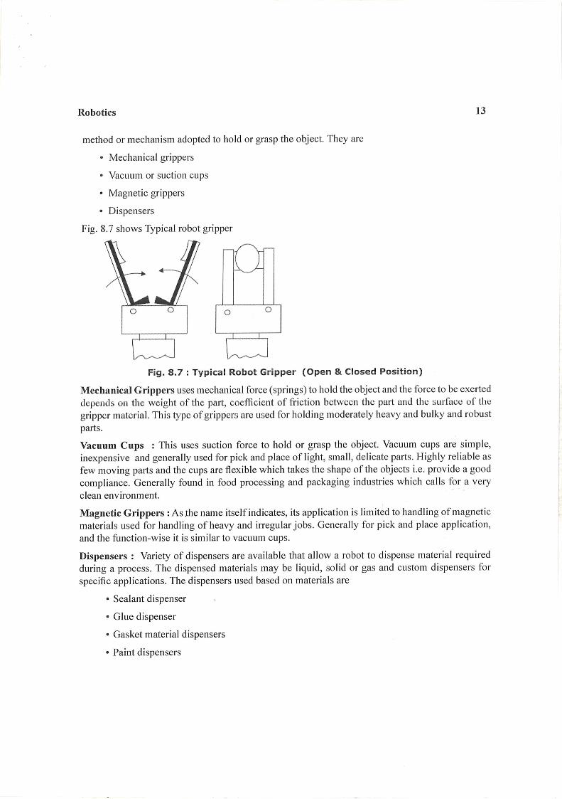
Robot Technology
*** This study material is in addition to the pdf material which was shared *****
Dr. K. M. Sathish Kumar Professor and Head, Dept. of ME, BMSIT&M
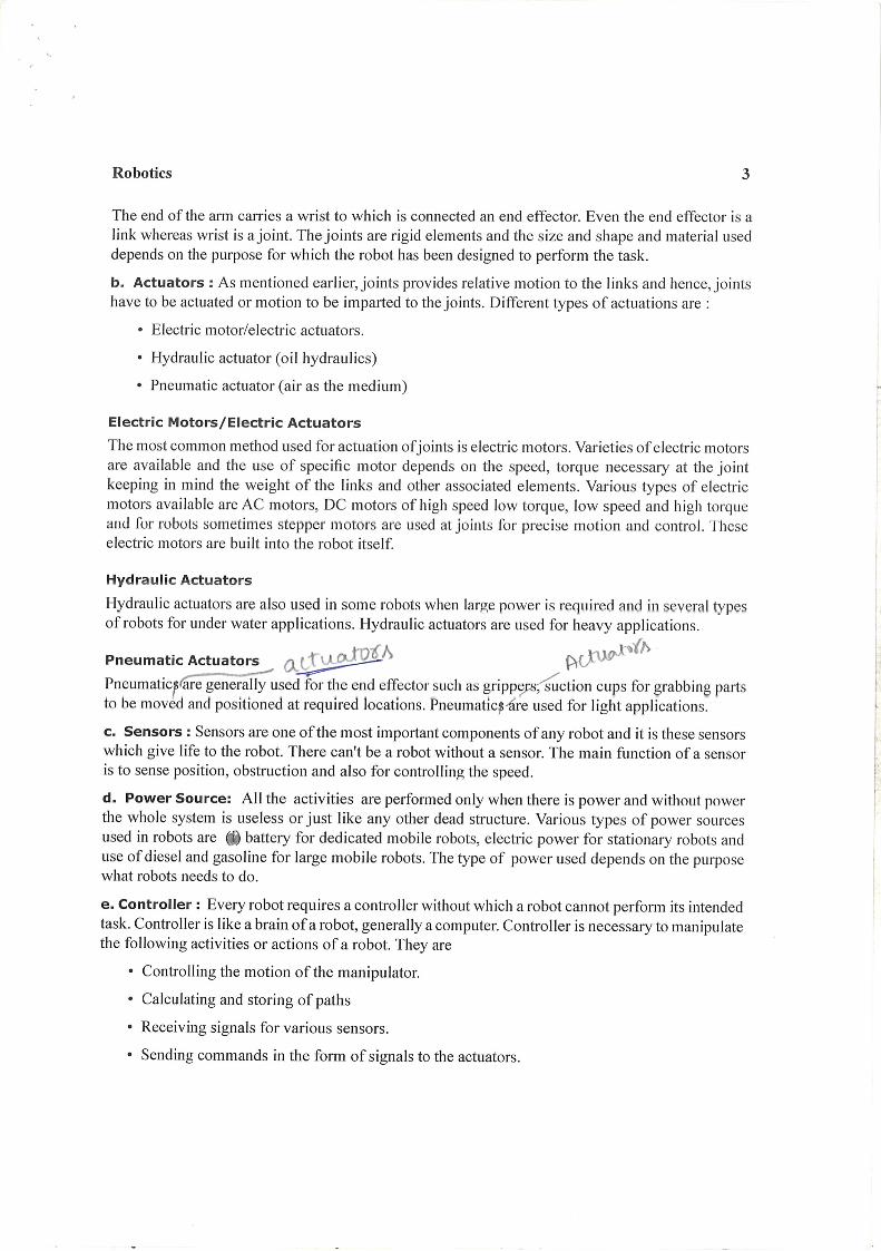
Robot Drive System: The Robot drive systems are used to actuate robotic joints. The
three types of drive systems that are generally used for industrial robots are:
Hydraulic drive Electric drive Pneumatic drive
Hydraulic drive system: It gives a robot great speed and strength. Hence they are
adopted for large industrial robots. This type of drives are preferred in environments in
which the use of electric drive robots may cause fire hazards.
Disadvantages of a hydraulic robot:
Occupy more floor space for ancillary equipment in addition to that required by the
robot.
There are problems such as leaks
Electric drive system: This provides a robot with less speed and strength. Electric drive
systems are adopted for smaller robots. Robots supported by electric drive systems are
more accurate, exhibit better repeatability and are cleaner to use. Electrically driven robots
are the most commonly available. Electric drives are generally favoured in commercial
applications, as they readily take advantage of the advances in electric motor technology
made in recent years, and owing to their ready compatibility to computing systems. Electric
motors constitute the main type of electric drive system. Variety of electric motors are
available and the use of specific motor depends on the speed and torque necessitated at
the joint. Various types of electric motors available are AC motors, DC motors, stepper
motors and servo motors. Typically, servo-motors or steeper motors are used.
Pneumatic drive system: Generally used for smaller robots. Have fewer axes of
movement. Carry out simple pick-and-place material-handling operations, such as picking
up an object at one location and placing it at another location. These operations are
Computer Integrated Manufacturing 17ME62 Module 4
Dr. K. M. Sathish Kumar, Dept. of ME, BMSIT&M
generally simple and have short cycle times. Here pneumatic power can be used for sliding
or rotational joints. Pneumatic robots are less expensive than electric or hydraulic robots.
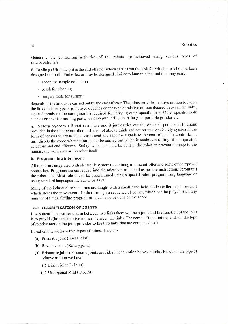
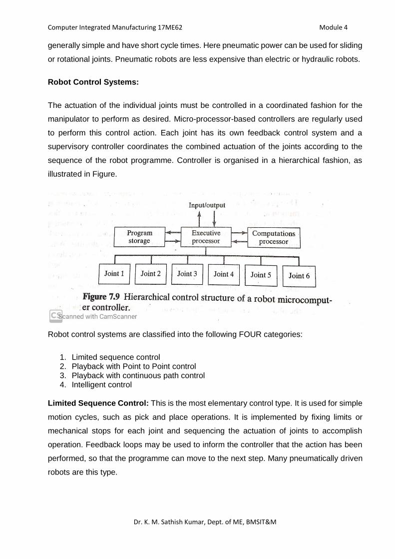
Robot Control Systems:
The actuation of the individual joints must be controlled in a coordinated fashion for the
manipulator to perform as desired. Micro-processor-based controllers are regularly used
to perform this control action. Each joint has its own feedback control system and a
supervisory controller coordinates the combined actuation of the joints according to the
sequence of the robot programme. Controller is organised in a hierarchical fashion, as
illustrated in Figure.
Robot control systems are classified into the following FOUR categories:
1. Limited sequence control 2. Playback with Point to Point control 3. Playback with continuous path control 4. Intelligent control
Limited Sequence Control: This is the most elementary control type. It is used for simple
motion cycles, such as pick and place operations. It is implemented by fixing limits or
mechanical stops for each joint and sequencing the actuation of joints to accomplish
operation. Feedback loops may be used to inform the controller that the action has been
performed, so that the programme can move to the next step. Many pneumatically driven
robots are this type.
Computer Integrated Manufacturing 17ME62 Module 4
Dr. K. M. Sathish Kumar, Dept. of ME, BMSIT&M
Playback with Point to Point Control: This method represents a more sophisticated form
of control than limited sequence robots. Playback control means that the controller has a
memory to record the sequence of motions in a given work cycle, as well as associated
locations and other parameters and then plays back the work cycle during programme
execution. It is this playback feature that gives the control type its name. In Point to Point
(PTP) control, individual positions of the robot arm are recorded in the memory. These
positions include both mechanical stops for each joint and the set of values that represent
locations in the range of each joint. Feedback control is used to confirm that the individual
joints achieve the specified locations in the programme.
Playback with Continuous Path Control: Continuous path robots have the same
playback capability as the previous one. Continuous path control refers to a control system
capable of continuous simultaneous control of two or more axes. Continuous path control
has a Greater storage capacity—the number of locations that can be stored is greater than
compared to point to point. Interpolation calculations may be used, especially linear and
circular interpolations.
Intelligent Control: An intelligent robot is one that exhibits behaviour that makes it seem
intelligent. Some of the characteristics that make a robot appear intelligent include the
capacity to:
Interact with its ambient surroundings
Make decisions when things go wrong during the work cycle
Communicate with humans
Make computations during the work cycle
Respond to advanced sensor inputs.
In addition, robots with intelligent control possess the playback capability for both PTP or
Continuous path control. These features require a high level of computer control and an
advanced programming language to input the decision-making logic and other
‘intelligence’ into the memory.
Accuracy and Repeatability: The capacity of the robot to position and orient the end of
its wrist with accuracy and repeatability is an important control attribute in nearly all
industrial applications. Some assembly applications require that objects be located with a
Computer Integrated Manufacturing 17ME62 Module 4
Dr. K. M. Sathish Kumar, Dept. of ME, BMSIT&M
precision of 0.05 mm. Other applications, such as spot welding, usually require accuracies
of 0.5 to 1.0 mm.
There are several terms that must defined in the context of this discussion:
Control resolution
Accuracy
Repeatability
Control resolution: The capability of the robot’s controller and positioning system to
divide the range of the joint into closely spaced points that can be identified by the
controller. These points are called addressable points because they represent locations to
which the robot joint can be moved by the controller.
Accuracy: The robot’s ability to position its end-of-wrist at a desired location in the work
volume. “How close does the robot get to the desired point”. This measures the distance
between the specified position, and the actual position of the robot end effector.
Repeatability: How close will the robot be to the same position as the same move made
before”. A measure of the error or variability when repeatedly reaching for a single position.
Repeatability is often smaller than accuracy
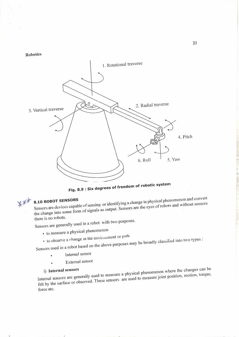
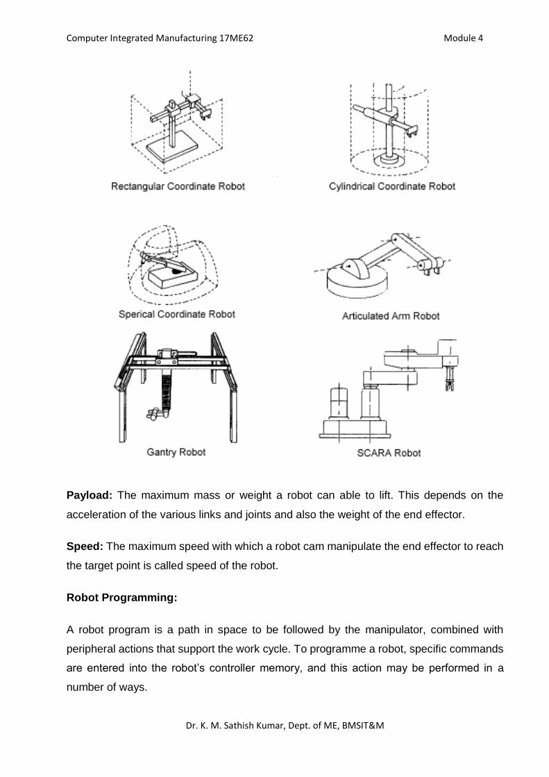
Work volume / Work space / Work envelope: The work volume or work envelope is the
three-dimensional space in which the robot can manipulate the end of its wrist. A space
on which a robot can move and operate its wrist end is called as a work volume. It is also
referred as the work envelope and work space. Work volume is determined by the number
and types of joints in the manipulator, the ranges of the various joints, and the physical
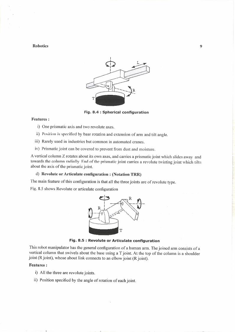
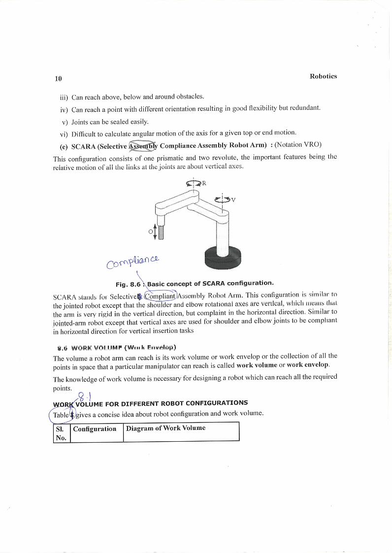
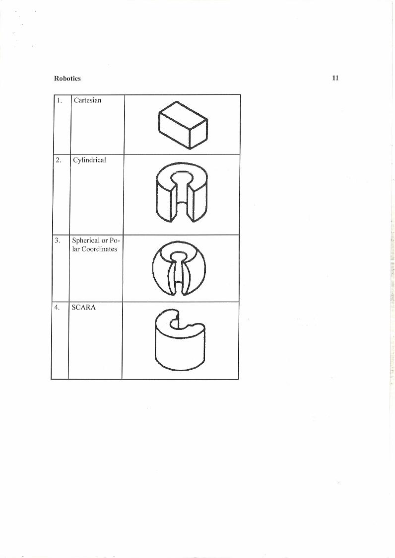
size of the links. Its actual shape is dependent on the robot’s configuration: Polar robotic
configuration tends to produce a spherical (or near-spherical) work volume. Cylindrical
configuration has a cylindrical work envelope. Cartesian co-ordinate robot produces a
rectangular work volume.
Computer Integrated Manufacturing 17ME62 Module 4
Dr. K. M. Sathish Kumar, Dept. of ME, BMSIT&M
Payload: The maximum mass or weight a robot can able to lift. This depends on the
acceleration of the various links and joints and also the weight of the end effector.
Speed: The maximum speed with which a robot cam manipulate the end effector to reach
the target point is called speed of the robot.
Robot Programming:
A robot program is a path in space to be followed by the manipulator, combined with
peripheral actions that support the work cycle. To programme a robot, specific commands
are entered into the robot’s controller memory, and this action may be performed in a
number of ways.
Computer Integrated Manufacturing 17ME62 Module 4
Dr. K. M. Sathish Kumar, Dept. of ME, BMSIT&M
All robot programming may be broadly classified into TWO methods. They are:
I. On-line Programming
II. Off-line Programming
For industrial robots with digital computers as controllers three programming methods can
be distinguished.
(a) Lead-through programming
(b) Computer-like robot programming languages
(c) Off-line programming.
In case of Lead through programming, Task is ‘taught’ to the robot by manually moving the
manipulator through the required motion cycle and simultaneously entering the programme
into the controller memory for playback. Two methods are used for teaching:
Powered lead-through
Manual lead-through.
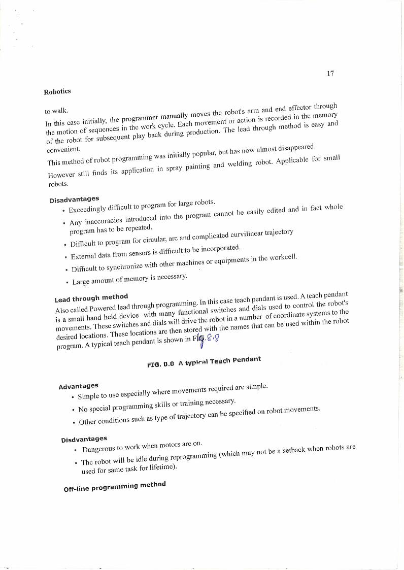
Powered lead-through: It is commonly used as the programming method for playback
robots with point-to-point control. It involves the use of a teach pendant (handheld control
box) that has toggle switches and/or contact buttons for controlling the movement of the
manipulator joints. Using the toggle switches or buttons, the programmer power drives the
robot arm to the desired positions, in sequence, and records the positions into memory.
During subsequent playback, the robot moves through the sequence of positions under its
own power.
Manual lead-through: It is convenient for programming playback robots with
continuous path control. This programming method requires the operator to physically
grasp the end-of-arm or tool attached to the arm and manually move it through the motion
sequence, recording the path into memory. Because the robot arm itself may have
significant mass and would therefore he difficult to move, a special programming device
often replaces the actual robot for the teach procedure. The programming device has the
same joint configuration as the robot and it is equipped with a trigger handle (or other
control switch), which is activated when the operator wishes to record motions into
memory. The motions are recorded as a series of closely spaced points. During playback,
Computer Integrated Manufacturing 17ME62 Module 4
Dr. K. M. Sathish Kumar, Dept. of ME, BMSIT&M
the path is recreated by controlling the actual robot arm through the same sequence of
points.
Robot Programming Languages: The use of textual programming languages became
an appropriate programming method as digital computers took over the control function in
robotics. These computer-like programming languages are really-online/off-fine methods
of programming.
Commonly used Robot Programming Languages are:
Motion programming
AML (A Manufacturing Language)
VAL (Variable Assembly Language)
AL Robot Language (Artificial Lab)
Kuka Robot Language by Kuka Company
RAPID by ABB
BAPS by Bosch
Off–line Programming: The trouble with online programming techniques is that the robot
must be taken out of production for a certain length of time to accomplish the programming.
Off-line programming permits the robot program to be prepared at a remote computer
terminal and downloaded to the robot controller for execution. The advantage of true offline
programming is that new programs can be prepared and downloaded to the robot without
interrupting production.
Industrial Robot Applications:
The general characteristics of industrial work situations that tend to promote the
substitution of robots for human labour are the following:
Hazardous work for humans: In situations where the work environment is unsafe,
unhealthy, uncomfortable, or otherwise unpleasant for humans, robot application may be
considered.
Repetitive work cycle: If the sequence of elements in the work cycle is the same, and the
elements consist of relatively simple motions, robots usually perform the work with greater
consistency and repeatability
Computer Integrated Manufacturing 17ME62 Module 4
Dr. K. M. Sathish Kumar, Dept. of ME, BMSIT&M
Difficult handling for humans: If the task requires the use of heavy or difficult-to-handle
parts or tools for humans, robots may be able to perform the operation more efficiently.
Multi-shift operation: A robot can replace two or three workers at a time in second or
third shifts, thus they can provide a faster financial payback
Infrequent changeovers: Robot use is justified for long production runs where there are
infrequent changeovers, as opposed to batch or job shop production where changeovers
are more frequent.
Part position and orientation are established in the work cell: Robots generally don’t
have vision capabilities, which means parts must be precisely placed and oriented for
successful robotic operations.
Industrial Robot Applications can be divided into:
Material-handling Applications Processing Operations Applications Assembly and Inspection Applications
Material-handling applications: In material handling, robots move parts between various
locations by means of a gripper type end effector. Two sub-divisions may be noted in
material handling:
Material transfer
Machine loading and/or unloading.
Material transfer: The application involves Pick and place operations, Part re-orientation,
Palletising, de-palletising, Stacking and Insertion operations
Machine loading and/or unloading: Here the chief purpose is to transfer parts into or
out- of a production machine. The three possible cases are:
Machine loading: where the robot loads the machine only
Machine unloading: where the robot unloads the machine only
Machine loading and unloading—where the robot performs both actions.
Computer Integrated Manufacturing 17ME62 Module 4
Dr. K. M. Sathish Kumar, Dept. of ME, BMSIT&M
Machine loading and/or unloading is used in the following processes: die casting, plastic
moulding, metal machining operations, forging, press-working, and heat treating
Processing operations applications: In processing operations, the robot performs some
processing actions such as grinding, milling, etc. on the work part. The end effector is
equipped with the specialised tool required for the process. The tool is moved relative to
the surface of the work part. Robot performs a processing procedure on the part. The robot
is equipped with some type of process tooling as its end effector. Manipulates the tooling
relative to the working part during the cycle.
Industrial robot applications in the processing operations include:
(1) Spot welding
(2) Continuous arc welding
(3) Spray painting
(4) Metal cutting and deburring operations
(5) Various machining operations like drilling, grinding, laser and waterjet cutting and
riveting.
(6) Rotating and spindle operations
(7) Adhesives and sealant dispensing
Assembly and Inspection applications: The applications involve both material handling
and the manipulation of a tool. They typically include components to build the product and
to perform material handling operations. One of the well suited area for robotics assembly
is the insertion of odd electronic components. Used for identifying flaws in raw materials
and finished parts. Inspection probe can be attached to the wrist of the robot. (Worked as
a Tool, a classification of End effector)
***************
Computer Integrated Manufacturing CIM 17ME62 VI Sem Mechanical
Dr. K. M. Sathish Kumar, Dept. of ME, BMSIT&M
ADDITIVE MANUFACTURING SYSTEMS
Dr. K. M. Sathish Kumar Professor and HoD, Dept. of ME, BMSIT&M
Introduction:
The term Rapid Prototyping (or RP) is used in a variety of industries to describe a process for rapidly
creating a system or part representation before final release or commercialization. In other words, the
emphasis is on creating something quickly and that the output is a prototype or basis model from
which further models and eventually the final product will be derived. In a product development
context, the term rapid prototyping was used widely to describe technologies which created physical
prototypes directly from digital data.
Users of RP technology have come to realize that this term is inadequate and does not effectively
describe more recent applications of the technology. Improvements in the quality of the output from
these machines have meant that there is a much closer link to the final product. Many parts are in fact
now directly manufactured in these machines; so it is not possible for us to label them as “prototypes.”
The term Rapid Prototyping also overlooks the basic principle of these technologies in that they all
fabricate parts using an additive approach. A recently formed Technical Committee within ASTM
International agreed that new terminology should be adopted. While this is still under debate, recently
adopted ASTM consensus standards now use the term Additive Manufacturing.
Referred to in short as AM, the basic principle of this technology is that a model, initially generated
using a three-dimensional Computer Aided Design (3D CAD) system, can be fabricated directly
without the need for process planning.
Additive Manufacturing (AM) is defined as a process by which digital 3D design data is used
to build up a component in layers by depositing material. Commonly known as “3D Printing”.
Computer Integrated Manufacturing CIM 17ME62 VI Sem Mechanical
Dr. K. M. Sathish Kumar, Dept. of ME, BMSIT&M
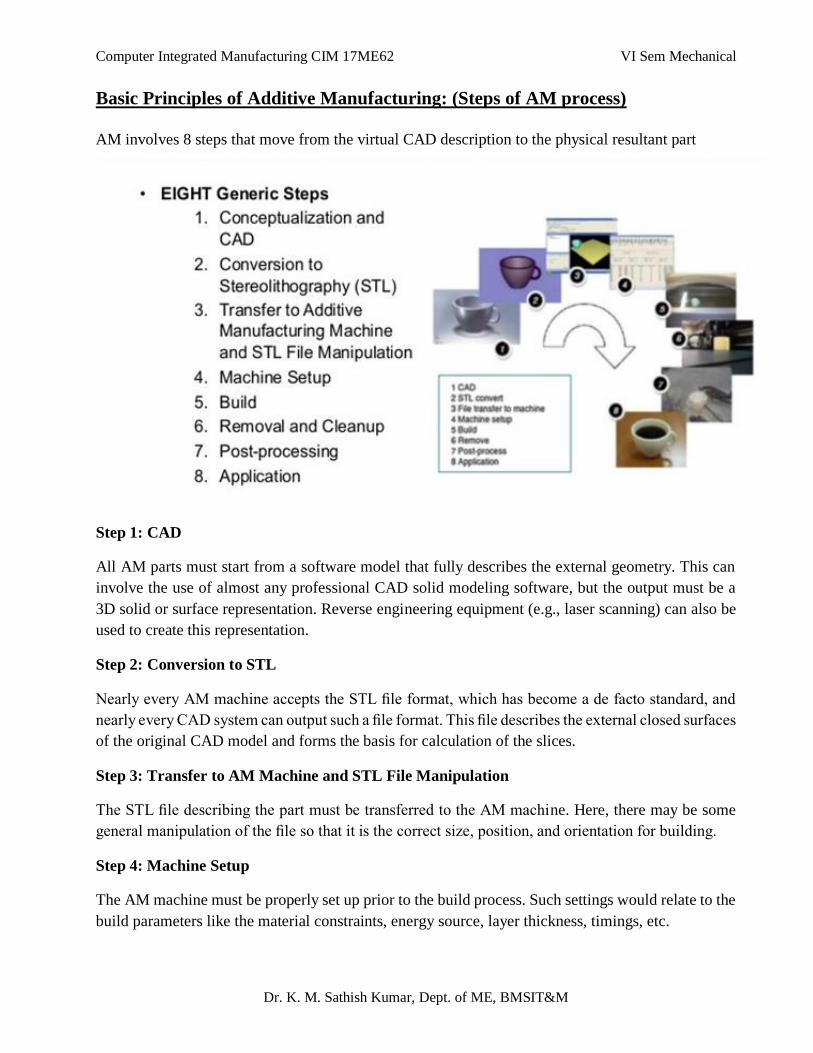
Basic Principles of Additive Manufacturing: (Steps of AM process)
AM involves 8 steps that move from the virtual CAD description to the physical resultant part
Step 1: CAD
All AM parts must start from a software model that fully describes the external geometry. This can
involve the use of almost any professional CAD solid modeling software, but the output must be a
3D solid or surface representation. Reverse engineering equipment (e.g., laser scanning) can also be
used to create this representation.
Step 2: Conversion to STL
Nearly every AM machine accepts the STL file format, which has become a de facto standard, and
nearly every CAD system can output such a file format. This file describes the external closed surfaces
of the original CAD model and forms the basis for calculation of the slices.
Step 3: Transfer to AM Machine and STL File Manipulation
The STL file describing the part must be transferred to the AM machine. Here, there may be some
general manipulation of the file so that it is the correct size, position, and orientation for building.
Step 4: Machine Setup
The AM machine must be properly set up prior to the build process. Such settings would relate to the
build parameters like the material constraints, energy source, layer thickness, timings, etc.
Computer Integrated Manufacturing CIM 17ME62 VI Sem Mechanical
Dr. K. M. Sathish Kumar, Dept. of ME, BMSIT&M
Step 5: Build
Building the part is mainly an automated process and the machine can largely carry on without
supervision. Only superficial monitoring of the machine needs to take place at this time to ensure no
errors have taken place like running out of material, power or software glitches, etc.
Step 6: Removal
Once the AM machine has completed the build, the parts must be removed. This may require
interaction with the machine, which may have safety interlocks to ensure for example that the
operating temperatures are sufficiently low or that there are no actively moving parts.
Step 7: Post processing
Once removed from the machine, parts may require an amount of additional cleaning up before they
are ready for use. Parts may be weak at this stage or they may have supporting features that must be
removed. This therefore often requires time and careful, experienced manual
Step 8: Application
Parts may now be ready to be used. However, they may also require additional treatment before they
are acceptable for use. For example, they may require priming and painting to give an acceptable
surface texture and finish. Treatments may be laborious and lengthy if the finishing requirements are
very demanding.
Advantages of Additive Manufacturing Technologies:
Are as follows:
1. Variety is free – Changing a part is simple and can be made easily in the original CAD file
and the new print can be taken easily.
2. Complexity is free – Printing of a complex part costs less than simple cubes of the same size.
The less solid or more complex object, it can be fastly and cheaply made through additive
manufacturing.
3. No need for assembly – Hinges and bicycle chains are some of the moving parts which can
be printed in metal directly into the product and thus reduce the part numbers.
4. Little-skill manufacturing – Professionals take care of the complicated parts with specific
parameters and high-tech applications, children in the elementary school have created their
on figures by use of 3D printing processes.
Computer Integrated Manufacturing CIM 17ME62 VI Sem Mechanical
Dr. K. M. Sathish Kumar, Dept. of ME, BMSIT&M
5. Few Constraints – In the CAD software one can dream anything and design the same and
create it with additive manufacturing.
6. Various shades of materials – In the CAD files, the engineers can program parts to have
specific colors and printers can use materials of any color to print them.
7. Lower energy consumption: AM saves energy by eliminating production steps, using
substantially less material, enabling reuse of by-products, and producing lighter products
8. Less Waste: Building objects up layer by layer, instead of traditional machining processes
that cut away material can reduce material needs and costs by up to 90%. AM can also reduce
the “cradle-to-gate” environmental footprints of component manufacturing through avoidance
of the tools, dies, and materials scrap associated with CM processes. Additionally, AM
reduces waste by lowering human error in production.
9. Reduced time to market: Items can be fabricated as soon as the 3-D digital description of
the part has been created, eliminating the need for expensive and time-consuming part tooling
and prototype fabrication.
10. Innovation: AM enables designs with novel geometries that would be difficult or impossible
to achieve using CM processes, which can improve a component’s engineering performance.
Novel geometries enabled by AM technologies can also lead to performance and
environmental benefits in a component’s product application.
11. Part Consolidation: The ability to design products with fewer, more complex parts, rather
than a large number of simpler parts – is the most important of these benefits. Reducing the
number of parts in an assembly immediately cuts the overhead associated with documentation
and production planning and control. Also, fewer parts mean less time and labor is required
for assembling the product, again contributing to a reduction in overall manufacturing costs.
The “footprint” of the assembly line may also become smaller, further cutting costs
12. Lightweighting: With the elimination of tooling and the ability to create complex shapes,
AM enables the design of parts that can often be made to the same functional specifications
as conventional parts, but with less material.
13. Agility to manufacturing operations: Additive techniques enable rapid response to markets
and create new production options outside of factories, such as mobile units that can be placed
near the source of local materials. Spare parts can be produced on demand, reducing or
eliminating the need for stockpiles and complex supply chains.
Computer Integrated Manufacturing CIM 17ME62 VI Sem Mechanical
Dr. K. M. Sathish Kumar, Dept. of ME, BMSIT&M
Disadvantages of Additive Manufacturing Technologies:
1. Production cost is high – With the use of techniques other than additive manufacturing, parts
can be made faster and hence the extra time can lead to higher costs. Besides, high-quality of
additive manufacturing machines may cost high.
2. Discontinuous production process – To prevent economies of scale, parts can only be
printed one at a time.
3. Requires post-processing – The surface finish and dimensional accuracy are of low quality
than other manufacturing methods.
4. Slow build rates – Some of the printers lay down material at speed of one to five cubic inches
per hour. Depending on the part needed the other manufacturing processes may be higher.
5. Considerable effort in application design and setting process parameters – Material
design needs vast knowledge and additive manufacturing machine is needed to make quality
parts.
6. Poor mechanical properties – Layering and multiple interfaces can cause defects in the
product.
7. Post-processing is needed – Surface finish and dimensional accuracy may be of low quality
than other manufacturing methods.
Applications of Additive Manufacturing Technologies:
Automotive applications
Aerospace applications
Biomedical applications
Consumer goods applications
Space applications
Health care applications
Artistic Industry
Architectural Industry
Computer Integrated Manufacturing CIM 17ME62 VI Sem Mechanical
Dr. K. M. Sathish Kumar, Dept. of ME, BMSIT&M
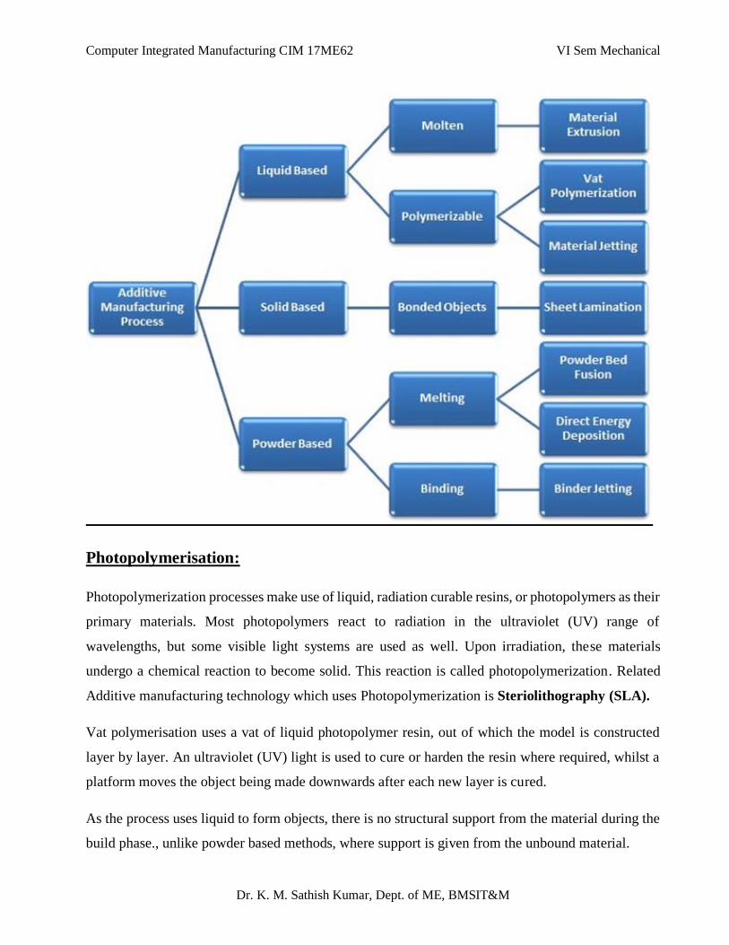
Additive Manufacturing Processes:
Additive manufacturing processes are classified into seven areas on the basis of
Type of materials used
Deposition technique, and
The way the material is fused or solidified
These classifications have been developed by the ASTM International Technical Committee F42 on
additive manufacturing technologies.
The seven major additive manufacturing processes classified as per ASTM F42 are:
1. Photopolymerization
2. Material jetting
3. Binder jetting
4. Material extrusion
5. Powder Bed Fusion
6. Sheet Lamination
7. Direct Energy Deposition
Computer Integrated Manufacturing CIM 17ME62 VI Sem Mechanical
Dr. K. M. Sathish Kumar, Dept. of ME, BMSIT&M
Photopolymerisation:
Photopolymerization processes make use of liquid, radiation curable resins, or photopolymers as their
primary materials. Most photopolymers react to radiation in the ultraviolet (UV) range of
wavelengths, but some visible light systems are used as well. Upon irradiation, these materials
undergo a chemical reaction to become solid. This reaction is called photopolymerization. Related
Additive manufacturing technology which uses Photopolymerization is Steriolithography (SLA).
Vat polymerisation uses a vat of liquid photopolymer resin, out of which the model is constructed
layer by layer. An ultraviolet (UV) light is used to cure or harden the resin where required, whilst a
platform moves the object being made downwards after each new layer is cured.
As the process uses liquid to form objects, there is no structural support from the material during the
build phase., unlike powder based methods, where support is given from the unbound material.
Computer Integrated Manufacturing CIM 17ME62 VI Sem Mechanical
Dr. K. M. Sathish Kumar, Dept. of ME, BMSIT&M
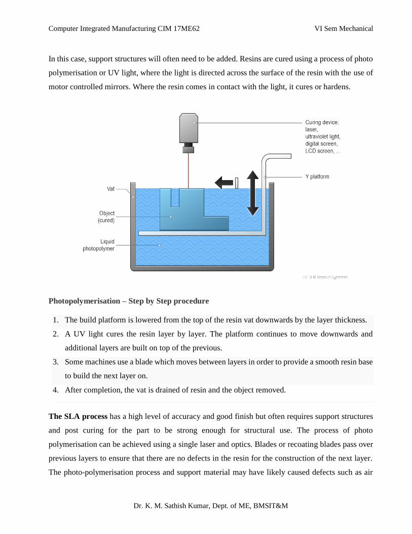
In this case, support structures will often need to be added. Resins are cured using a process of photo
polymerisation or UV light, where the light is directed across the surface of the resin with the use of
motor controlled mirrors. Where the resin comes in contact with the light, it cures or hardens.
Photopolymerisation – Step by Step procedure
1. The build platform is lowered from the top of the resin vat downwards by the layer thickness.
2. A UV light cures the resin layer by layer. The platform continues to move downwards and
additional layers are built on top of the previous.
3. Some machines use a blade which moves between layers in order to provide a smooth resin base
to build the next layer on.
4. After completion, the vat is drained of resin and the object removed.
The SLA process has a high level of accuracy and good finish but often requires support structures
and post curing for the part to be strong enough for structural use. The process of photo
polymerisation can be achieved using a single laser and optics. Blades or recoating blades pass over
previous layers to ensure that there are no defects in the resin for the construction of the next layer.
The photo-polymerisation process and support material may have likely caused defects such as air
Computer Integrated Manufacturing CIM 17ME62 VI Sem Mechanical
Dr. K. M. Sathish Kumar, Dept. of ME, BMSIT&M
gaps, which need to be filled with resin in order to achieve a high quality model. Typical layer
thickness for the process is 0.025 – 0.5mm.
Advantages:
High level of accuracy and good finish
Relatively quick process
Typically large build areas: objet 1000: 1000 x 800 x 500 and max model weight of 200 kg
Disadvantages:
Relatively expensive
Lengthly post processing time and reomval from resin
Limited material use of photo-resins
Often requires support structures and post curing for parts to be strong enough for structural
use
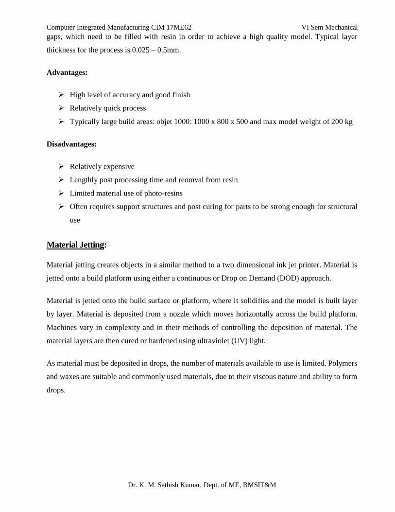
Material Jetting:
Material jetting creates objects in a similar method to a two dimensional ink jet printer. Material is
jetted onto a build platform using either a continuous or Drop on Demand (DOD) approach.
Material is jetted onto the build surface or platform, where it solidifies and the model is built layer
by layer. Material is deposited from a nozzle which moves horizontally across the build platform.
Machines vary in complexity and in their methods of controlling the deposition of material. The
material layers are then cured or hardened using ultraviolet (UV) light.
As material must be deposited in drops, the number of materials available to use is limited. Polymers
and waxes are suitable and commonly used materials, due to their viscous nature and ability to form
drops.
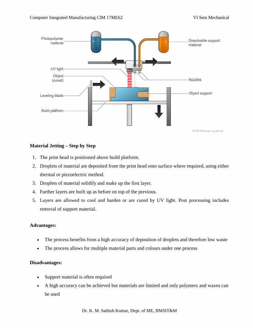
Computer Integrated Manufacturing CIM 17ME62 VI Sem Mechanical
Dr. K. M. Sathish Kumar, Dept. of ME, BMSIT&M
Material Jetting – Step by Step
1. The print head is positioned above build platform.
2. Droplets of material are deposited from the print head onto surface where required, using either
thermal or piezoelectric method.
3. Droplets of material solidify and make up the first layer.
4. Further layers are built up as before on top of the previous.
5. Layers are allowed to cool and harden or are cured by UV light. Post processing includes
removal of support material.
Advantages:
The process benefits from a high accuracy of deposition of droplets and therefore low waste
The process allows for multiple material parts and colours under one process
Disadvantages:
Support material is often required
A high accuracy can be achieved but materials are limited and only polymers and waxes can
be used
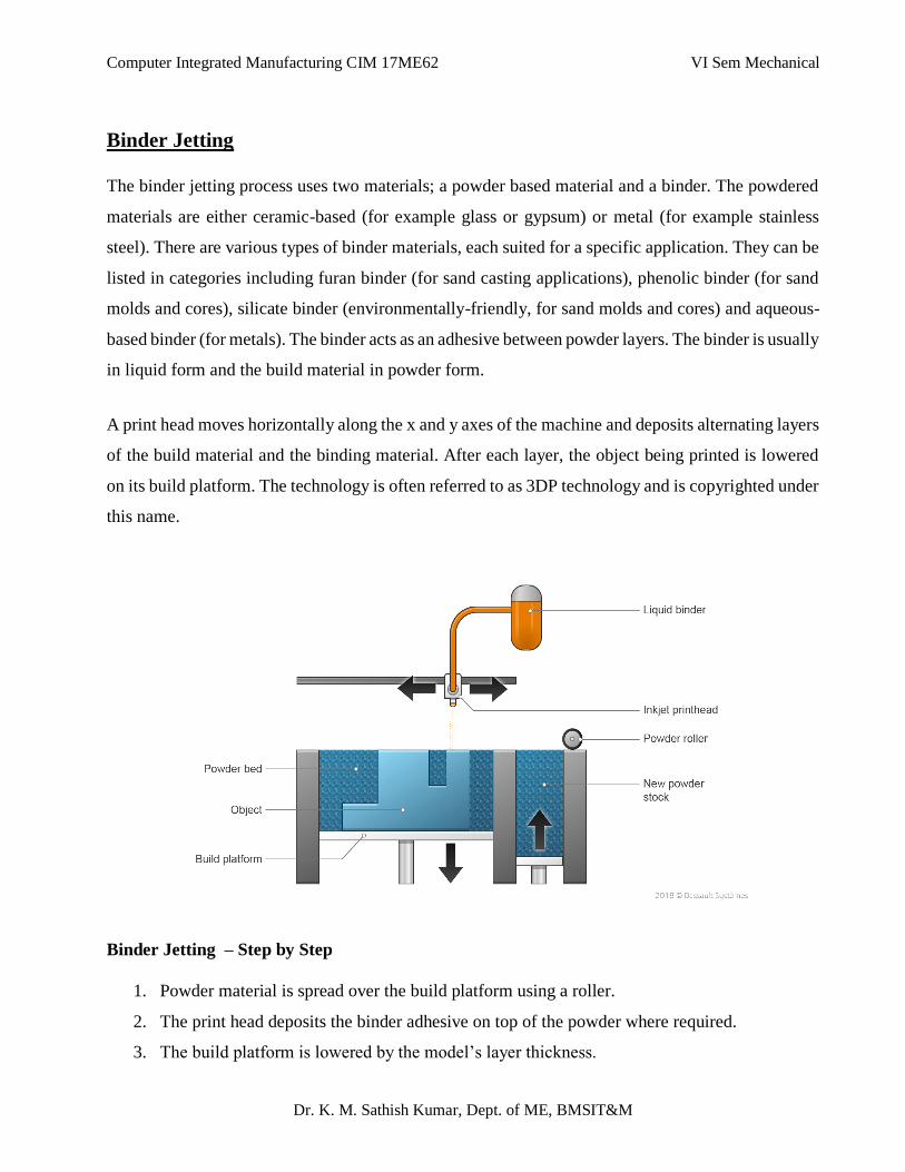
Computer Integrated Manufacturing CIM 17ME62 VI Sem Mechanical
Dr. K. M. Sathish Kumar, Dept. of ME, BMSIT&M
Binder Jetting
The binder jetting process uses two materials; a powder based material and a binder. The powdered
materials are either ceramic-based (for example glass or gypsum) or metal (for example stainless
steel). There are various types of binder materials, each suited for a specific application. They can be
listed in categories including furan binder (for sand casting applications), phenolic binder (for sand
molds and cores), silicate binder (environmentally-friendly, for sand molds and cores) and aqueous-
based binder (for metals). The binder acts as an adhesive between powder layers. The binder is usually
in liquid form and the build material in powder form.
A print head moves horizontally along the x and y axes of the machine and deposits alternating layers
of the build material and the binding material. After each layer, the object being printed is lowered
on its build platform. The technology is often referred to as 3DP technology and is copyrighted under
this name.
Binder Jetting – Step by Step
1. Powder material is spread over the build platform using a roller.
2. The print head deposits the binder adhesive on top of the powder where required.
3. The build platform is lowered by the model’s layer thickness.
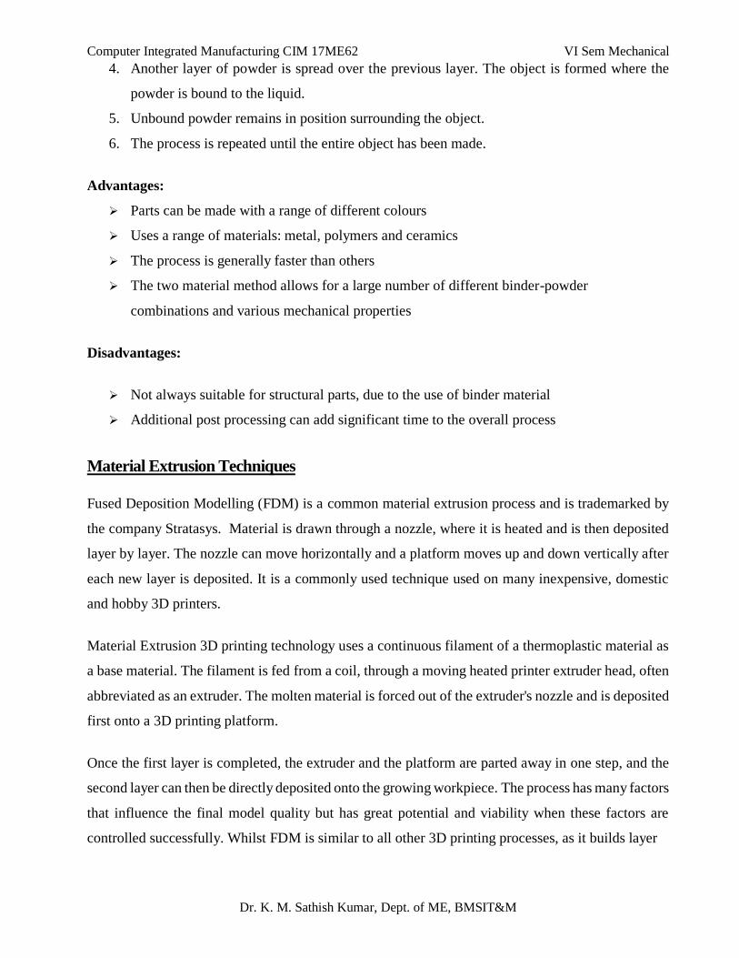
Computer Integrated Manufacturing CIM 17ME62 VI Sem Mechanical
Dr. K. M. Sathish Kumar, Dept. of ME, BMSIT&M
4. Another layer of powder is spread over the previous layer. The object is formed where the
powder is bound to the liquid.
5. Unbound powder remains in position surrounding the object.
6. The process is repeated until the entire object has been made.
Advantages:
Parts can be made with a range of different colours
Uses a range of materials: metal, polymers and ceramics
The process is generally faster than others
The two material method allows for a large number of different binder-powder
combinations and various mechanical properties
Disadvantages:
Not always suitable for structural parts, due to the use of binder material
Additional post processing can add significant time to the overall process
Material Extrusion Techniques
Fused Deposition Modelling (FDM) is a common material extrusion process and is trademarked by
the company Stratasys. Material is drawn through a nozzle, where it is heated and is then deposited
layer by layer. The nozzle can move horizontally and a platform moves up and down vertically after
each new layer is deposited. It is a commonly used technique used on many inexpensive, domestic
and hobby 3D printers.
Material Extrusion 3D printing technology uses a continuous filament of a thermoplastic material as
a base material. The filament is fed from a coil, through a moving heated printer extruder head, often
abbreviated as an extruder. The molten material is forced out of the extruder's nozzle and is deposited
first onto a 3D printing platform.
Once the first layer is completed, the extruder and the platform are parted away in one step, and the
second layer can then be directly deposited onto the growing workpiece. The process has many factors
that influence the final model quality but has great potential and viability when these factors are
controlled successfully. Whilst FDM is similar to all other 3D printing processes, as it builds layer
Computer Integrated Manufacturing CIM 17ME62 VI Sem Mechanical
Dr. K. M. Sathish Kumar, Dept. of ME, BMSIT&M
by layer, it varies in the fact that material is added through a nozzle under constant pressure and in a
continuous stream. This pressure must be kept steady and at a constant speed to enable accurate
results. Material layers can be bonded by temperature control or through the use of chemical agents.
Material is often added to the machine in spool form as shown in the diagram.
The extruder head is moved under computer control. At least three axes are required for the extruder
to move in Cartesian architectures. A wide variety of materials can be extruded, the most popular
being thermoplastics, such as Acrylonitrile Butadiene Styrene (ABS), PolyLactic Acid (PLA), High-
Impact Polystyrene (HIPS), Thermoplastic PolyUrethane (TPU), aliphatic PolyAmides (PA, also
known as Nylon), and more recently high performance plastics such as PolyEther Ether Ketone PEEK
or PolyEtherimide PEI.
Material Extrusion – Step by Step
1. First layer is built as nozzle deposits material where required onto the cross sectional area of
first object slice.
2. The following layers are added on top of previous layers.
3. Layers are fused together upon deposition as the material is in a melted state.
Computer Integrated Manufacturing CIM 17ME62 VI Sem Mechanical
Dr. K. M. Sathish Kumar, Dept. of ME, BMSIT&M
Advantages:
Widespread and inexpensive process
ABS plastic can be used, which has good structural properties and is easily accessible
Disadvantages:
The nozzle radius limits and reduces the final quality
Accuracy and speed are low when compared to other processes and accuracy of the final
model is limited to material nozzle thickness
Constant pressure of material is required in order to increase quality of finish
Powder Bed Fusion Sintering Techniques
Powder bed fusion (PBF) methods use either a laser or electron beam to melt and fuse material powder
together. In this method, the layers of powder are fused together using a heat source, such as a laser
or election beam. The Powder Bed Fusion process includes the following commonly used printing
techniques: Direct metal laser sintering (DMLS), Electron beam melting (EBM), Selective heat
sintering (SHS), Selective laser melting (SLM) and Selective laser sintering (SLS).
Selective Laser Sintering (SLS) is the process of compacting and forming a solid mass of material by
heat and/or pressure without melting. Selective laser sintering (SLS) machines are made up of three
components: a heat source to fuse the material, a method to control this heat source and a mechanism
to add new layers of material over the previous.
Powder Bed Fusion – Step by Step
1. A layer, typically 0.1mm thick of material is spread over the build platform.
2. A laser fuses the first layer or first cross section of the model.
3. A new layer of powder is spread across the previous layer using a roller.
4. Further layers or cross sections are fused and added.
5. The process repeats until the entire model is created. Loose, unfused powder is remains in
position but is removed during post processing.
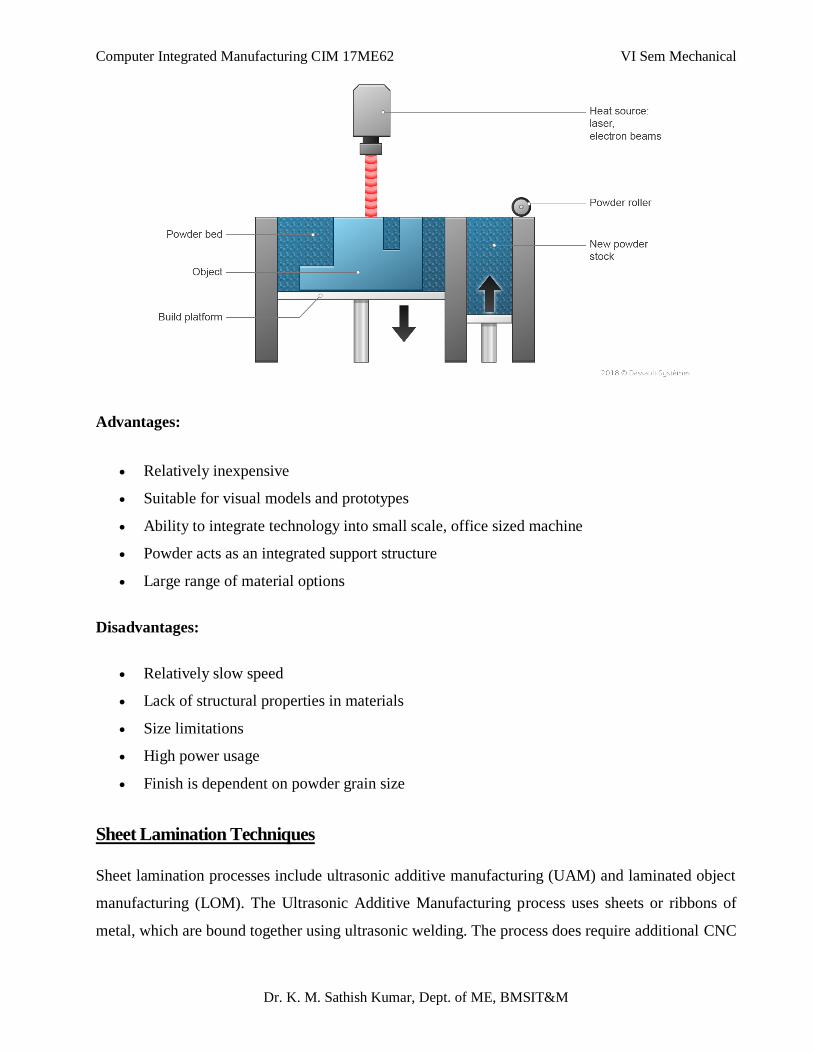
Computer Integrated Manufacturing CIM 17ME62 VI Sem Mechanical
Dr. K. M. Sathish Kumar, Dept. of ME, BMSIT&M
Advantages:
Relatively inexpensive
Suitable for visual models and prototypes
Ability to integrate technology into small scale, office sized machine
Powder acts as an integrated support structure
Large range of material options
Disadvantages:
Relatively slow speed
Lack of structural properties in materials
Size limitations
High power usage
Finish is dependent on powder grain size
Sheet Lamination Techniques
Sheet lamination processes include ultrasonic additive manufacturing (UAM) and laminated object
manufacturing (LOM). The Ultrasonic Additive Manufacturing process uses sheets or ribbons of
metal, which are bound together using ultrasonic welding. The process does require additional CNC
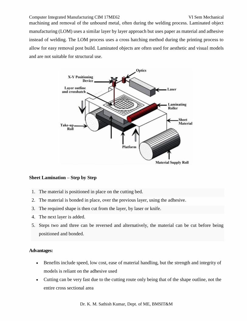
Computer Integrated Manufacturing CIM 17ME62 VI Sem Mechanical
Dr. K. M. Sathish Kumar, Dept. of ME, BMSIT&M
machining and removal of the unbound metal, often during the welding process. Laminated object
manufacturing (LOM) uses a similar layer by layer approach but uses paper as material and adhesive
instead of welding. The LOM process uses a cross hatching method during the printing process to
allow for easy removal post build. Laminated objects are often used for aesthetic and visual models
and are not suitable for structural use.
Sheet Lamination – Step by Step
1. The material is positioned in place on the cutting bed.
2. The material is bonded in place, over the previous layer, using the adhesive.
3. The required shape is then cut from the layer, by laser or knife.
4. The next layer is added.
5. Steps two and three can be reversed and alternatively, the material can be cut before being
positioned and bonded.
Advantages:
Benefits include speed, low cost, ease of material handling, but the strength and integrity of
models is reliant on the adhesive used
Cutting can be very fast due to the cutting route only being that of the shape outline, not the
entire cross sectional area
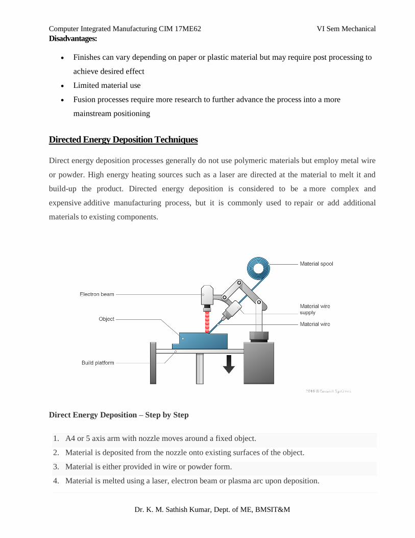
Computer Integrated Manufacturing CIM 17ME62 VI Sem Mechanical
Dr. K. M. Sathish Kumar, Dept. of ME, BMSIT&M
Disadvantages:
Finishes can vary depending on paper or plastic material but may require post processing to
achieve desired effect
Limited material use
Fusion processes require more research to further advance the process into a more
mainstream positioning
Directed Energy Deposition Techniques
Direct energy deposition processes generally do not use polymeric materials but employ metal wire
or powder. High energy heating sources such as a laser are directed at the material to melt it and
build-up the product. Directed energy deposition is considered to be a more complex and
expensive additive manufacturing process, but it is commonly used to repair or add additional
materials to existing components.
Direct Energy Deposition – Step by Step
1. A4 or 5 axis arm with nozzle moves around a fixed object.
2. Material is deposited from the nozzle onto existing surfaces of the object.
3. Material is either provided in wire or powder form.
4. Material is melted using a laser, electron beam or plasma arc upon deposition.
Computer Integrated Manufacturing CIM 17ME62 VI Sem Mechanical
Dr. K. M. Sathish Kumar, Dept. of ME, BMSIT&M
5. Further material is added layer by layer and solidifies, creating or repairing new material features
on the existing object.
Advantages
Ability to control the grain structure to a high degree, which lends the process to repair work
of high quality, functional parts
A balance is needed between surface quality and speed, although with repair applications,
speed can often be sacrificed for a high accuracy and a pre- determined microstructure
Disadvantages:
Finishes can vary depending on paper or plastic material but may require post processing to
achieve desired effect
Limited material use
Fusion processes require more research to further advance the process into a more
mainstream positioning
Recent trends in manufacturing:
The following are the commonly known practices used today that facilitate cost reduction, quality
improvement and flexibility in the manufacturing environment.
Lean Manufacturing
Demand Flow Manufacturing
Just-in-Time
Agile Manufacturing
Rapid Manufacturing
Flexible Manufacturing System
Advanced Planning and Scheduling
Lean Manufacturing: Lean manufacturing or lean productions, which is often known simply as
"Lean", is a production practice that considers the expenditure of resources for any goal other than
Computer Integrated Manufacturing CIM 17ME62 VI Sem Mechanical
Dr. K. M. Sathish Kumar, Dept. of ME, BMSIT&M
the creation of value for the end customer to be wasteful, and thus a target for elimination. Basically,
lean is centred on preserving value with less work.
Demand Flow Manufacturing: The most value and variation is created here: both in the product
and the service of supply. Demand Flow Manufacturing starts with the method for combining demand
and releasing orders into production. It works to optimise the allocation of asset capacity and
inventory to the required service level to the customer. The paradigm aim is a daily order release of
the exact product mix and volume according to customer demand.
Just-in-time (JIT): This is an inventory strategy that strives to improve a business's return on
investment by reducing in- process inventory and associated carrying costs. To meet JIT objectives,
the process relies on signals or Kanban between different points in the process, which tell production
when to make the next part. Kanban are usually 'tickets' but can be simple visual signals, such as the
presence or absence of a part on a shelf. Implemented correctly, JIT can improve a manufacturing
organization's return on investment, quality, and efficiency.
Agile Manufacturing: It is a term of light to an organisation that has created the processes, tools and
training to enable it to respond quickly to customer and market changes by still controlling cost and
quality. Agile manufacturing is seen as the next step after leaning the evolution of production and
methodical.
Rapid Manufacturing: It is an additive fabrication technique for manufacturing solid objects by the
sequential delivery of energy and materials to specify points in space to produce that part Crane
practice is to control the manufacturing process by computer using a mathematical model created
with the aid of computer.
Flexible Manufacturing System: Flexible manufacturing is a manufacturing system in which there
is some amount of flexibility that allows the system to react to the case of changes, whether predicted
or unpredicted. This flexibility generally considered in two categories
Machine Flexibility: It covers the system ability to be changed to produce new products type and
ability to change the order of operations executed on a part.
Routine Flexibility: Which consists the ability to use multiple machine to perform same operations
on a part, as well as the system ability to absorb large scale changes, such as in volume capacity or
capability.
Computer Integrated Manufacturing CIM 17ME62 VI Sem Mechanical
Dr. K. M. Sathish Kumar, Dept. of ME, BMSIT&M
Advanced Planning and Scheduling: This is also referred to as APS and advanced manufacturing
where there is a manufacturing management process by which raw materials and production capacity
are optimally allocated to meet demand. APS is especially well-suited to environments where simpler
planning methods cannot adequately address complex trade-offs between competing priorities.
Production scheduling is intrinsically very difficult due to the (approximately) factorial dependence
of the size of the solution space on the number of items/products to be manufactured.
Hybrid Manufacturing:
Hybrid manufacturing process combines two or more established manufacturing processes into a new
combined set-up whereby the advantages of each discrete process can be exploited synergistically. It
is also defined as the processes comprise a simultaneous acting of different (chemical, physical,
controlled) processing principles on the same processing zone.
The various Hybrid manufacturing process are as follows:
Mechanical machining and ECM
Mechanical machining and Electric Discharge Machining (EDM)
Mechanical machining and laser cutting
Laser cutting and EDM
Laser cutting and ECM
EDM and ECM
Turn-mill, mill-grind
Ultrasonic assisted mechanical machining
Ultrasonic assisted grinding
Ultrasonic assisted turning
Wire-EDM and etching
Laser heat treatment and sheet metal forming
Laser cladding and mechanical machining
Injection moulding and milling
*************
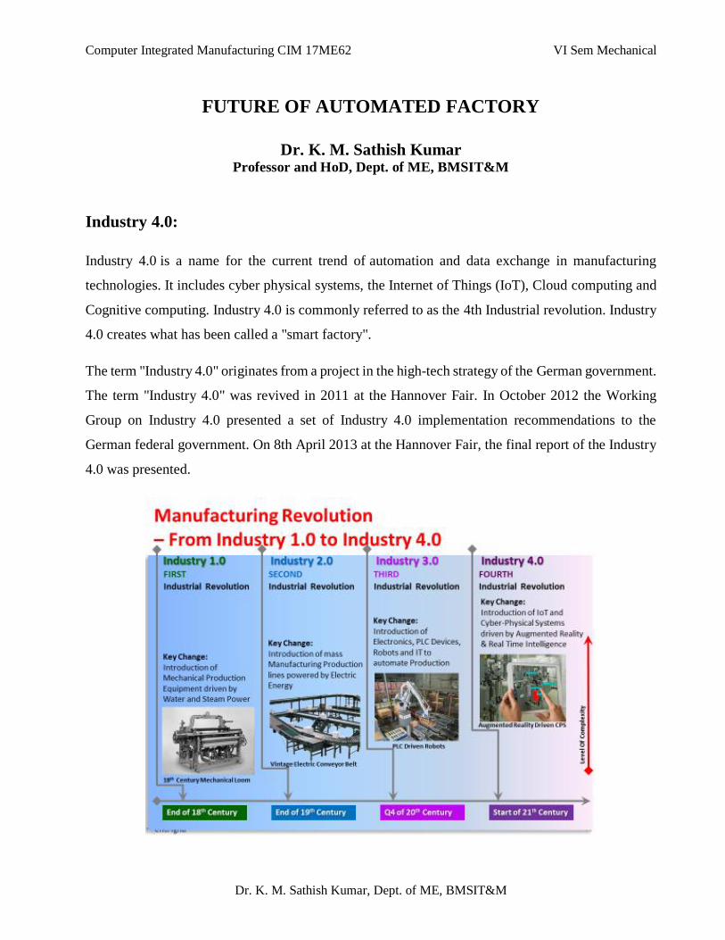
Computer Integrated Manufacturing CIM 17ME62 VI Sem Mechanical
Dr. K. M. Sathish Kumar, Dept. of ME, BMSIT&M
FUTURE OF AUTOMATED FACTORY
Dr. K. M. Sathish Kumar Professor and HoD, Dept. of ME, BMSIT&M
Industry 4.0:
Industry 4.0 is a name for the current trend of automation and data exchange in manufacturing
technologies. It includes cyber physical systems, the Internet of Things (IoT), Cloud computing and
Cognitive computing. Industry 4.0 is commonly referred to as the 4th Industrial revolution. Industry
4.0 creates what has been called a "smart factory".
The term "Industry 4.0" originates from a project in the high-tech strategy of the German government.
The term "Industry 4.0" was revived in 2011 at the Hannover Fair. In October 2012 the Working
Group on Industry 4.0 presented a set of Industry 4.0 implementation recommendations to the
German federal government. On 8th April 2013 at the Hannover Fair, the final report of the Industry
4.0 was presented.
Computer Integrated Manufacturing CIM 17ME62 VI Sem Mechanical
Dr. K. M. Sathish Kumar, Dept. of ME, BMSIT&M
Functions of Industry 4.0:
There are four design principles or functions or Features of Industry 4.0:
Interoperability: where machines, devices, sensors and people are connected and
communicated with each another.
Information transparency: The transparency afforded by Industry 4.0 technology provides
operators with vast amounts of useful information needed to make appropriate decisions.
Inter-connectivity allows operators to collect immense amounts of data and information from
all points in the manufacturing process, thus aiding functionality and identifying key areas
that can benefit from innovation and improvement.
Technical assistance: First, the ability of assistance systems to support humans by
aggregating and visualizing information comprehensively for making informed decisions and
solving urgent problems on short notice. Second, the ability of cyber physical systems to
physically support humans by conducting a range of tasks that are unpleasant, too exhausting,
or unsafe for their human co-workers.
Decentralized decision: the ability of cyber-physical systems to make simple decisions on
their own and perform their tasks as autonomously as possible.
Benefits of Industry 4.0 (Advantages of Industry 4.0):
Improved Productivity
Improved Efficiency
Increased Knowledge Sharing and Collaborative Working
Flexibility and Agility
Makes Compliance Easier
Better Customer Experience
Reduces Costs
Creates Innovation Opportunities
Higher Revenues
Increased Profitability
Getting A Return On Investment
Computer Integrated Manufacturing CIM 17ME62 VI Sem Mechanical
Dr. K. M. Sathish Kumar, Dept. of ME, BMSIT&M
Applications of Industry 4.0:
Internet of Objects (IoT)
Embedded Software
Big Data and Data Analytics
Machine to Machine Communication (M2M)
Cloud Solutions
Intelligent Robot Automation Systems
Augmented Reality
Simulation
Additive Manufacturing (3D PRINTING)
Cyber Security
Central Monitoring and Control (SCADA)
Mobile Devices
Smart Sensors (RFID, BARCODE)
Smart Objects
Remote control
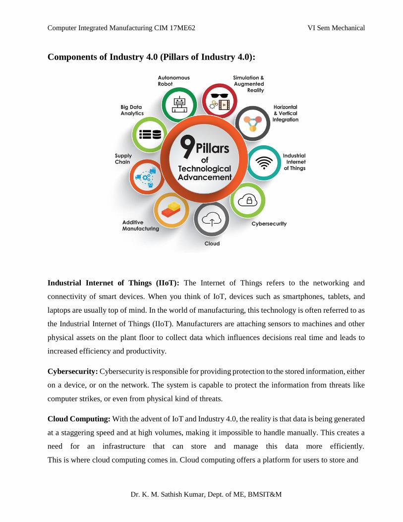
Computer Integrated Manufacturing CIM 17ME62 VI Sem Mechanical
Dr. K. M. Sathish Kumar, Dept. of ME, BMSIT&M
Components of Industry 4.0 (Pillars of Industry 4.0):
Industrial Internet of Things (IIoT): The Internet of Things refers to the networking and
connectivity of smart devices. When you think of IoT, devices such as smartphones, tablets, and
laptops are usually top of mind. In the world of manufacturing, this technology is often referred to as
the Industrial Internet of Things (IIoT). Manufacturers are attaching sensors to machines and other
physical assets on the plant floor to collect data which influences decisions real time and leads to
increased efficiency and productivity.
Cybersecurity: Cybersecurity is responsible for providing protection to the stored information, either
on a device, or on the network. The system is capable to protect the information from threats like
computer strikes, or even from physical kind of threats.
Cloud Computing: With the advent of IoT and Industry 4.0, the reality is that data is being generated
at a staggering speed and at high volumes, making it impossible to handle manually. This creates a
need for an infrastructure that can store and manage this data more efficiently.
This is where cloud computing comes in. Cloud computing offers a platform for users to store and
Computer Integrated Manufacturing CIM 17ME62 VI Sem Mechanical
Dr. K. M. Sathish Kumar, Dept. of ME, BMSIT&M
process vast amounts of data on remote servers. It enables organisations to use computer resources
without having to develop a computing infrastructure on premise. The term cloud computing refers
to information being stored in the “cloud”, accessed remotely via the Internet.
Big Data Analytics: The concept of big data applies to large, diverse and complex datasets that affect
the organizational decision making of a company concerning their strategy. Therefore, the increase
in level of data and improvements on technological capabilities accelerates firms’ competitive
advantage by increasing productivity, innovation and competition.
Autonomous Robots: Robots are used in manufacturing industries in order to solve complex tasks
which cannot be solved easily by a human. By the traditional automation strategy, companies could
not fully implement JIT strategies and continuous improvements if they do not opt for autonomous
robots. The usage of more industrial robots in factories accelerates with Industry 4.0. Robots could
be used in several areas such as production, logistics, distribution activities and could be controlled
remotely by humans thanks to the human robot cooperation.
Additive Manufacturing: Additive manufacturing, or 3D printing, is a key technology driving
Industry 4.0. Additive manufacturing is a process of converting digital 3D models to create parts with
a 3D printer layer by layer. Within the context of Industry 4.0, 3D printing is emerging as a valuable
digital manufacturing technology. AM offers a huge scope of possibilities for manufacturing
from tooling to mass customisation across virtually all industries.
Augmented Reality: Augmented reality bridges the gap between the digital and physical worlds by
superimposing virtual images or data onto a physical object. For this, the technology uses AR-capable
devices, such as smartphones, tablets and smart glasses. In the context of manufacturing, AR could
enable workers to speed up the assembly process and improve decision-making. For example, AR
glasses could be used to project data, such as layouts, assembly guidelines, sites of possible
malfunction, or a serial number of components, on the real part, facilitating faster and easier work
procedures.
Horizontal and Vertical Integration: Horizontal integration means every device and system at the
same level of manufacturing in the same facility or the other is connected with each other. As this
Computer Integrated Manufacturing CIM 17ME62 VI Sem Mechanical
Dr. K. M. Sathish Kumar, Dept. of ME, BMSIT&M
enables communication between systems in different facilities, jobs can be planned and adjusted by
the machines themselves. Vertical integration makes it even better. Every system and humans at all
hierarchy has all the data with required abstraction. Notable challenge faced in vertical integration is
the communication protocol.
Supply Chain: The manufacturing industry is moving towards a more digitised, automated, agile
and, ultimately, efficient operation and there is no better example of this than in the supply chain
network. In today’s world, the supply chain is a multi-faceted ecosystem linking product
development, manufacturing and distribution networks into one fully transparent and digitised
system.
Internet of Things (IOT):
Internet of Things (IoT) refers to a system of connected physical objects via the internet. The ‘thing’
in IoT can refer to a person or any device which is assigned through an IP address. A ‘thing’ collects
and transfers data over the internet without any manual intervention with the help of embedded
technology. It helps them to interact with the external environment or internal states to take the
decisions.
IOT Applications in Manufacturing:
Digital/Connected Factory
Facility Management
Production Flow Monitoring
Inventory Management
Plant Safety and Security
Quality Control
Packaging Optimization
Logistics and Supply Chain Optimization
Computer Integrated Manufacturing CIM 17ME62 VI Sem Mechanical
Dr. K. M. Sathish Kumar, Dept. of ME, BMSIT&M
Big-Data and Cloud Computing for IOT:
Big Data: Big Data means a large set of structured, unstructured or semi-structured data and analyzing
those data to get the insights of the business trend.
Cloud Computing: Cloud Computing gives the centralized platform to access the data from anywhere
in the world with the shared infrastructure. Thus, you can save a lot of money. Cloud computing
offers services to users on a pay-as-you-go model.
Cloud providers offer three primary services. These services are outlined below:
Infrastructure as a Service (IAAS): The Cloud service provider offers entire infrastructure along with
the maintenance related tasks.
Platform as a Service (PAAS): The Cloud provider offers resources like object storage, runtime,
queuing, databases, etc. However, the responsibility of configuration and implementation related
tasks depend on the consumer.
Software as a Service (SAAS): This service is the most facilitated one which offers all the necessary
settings and infrastructure provided IaaS for the platform and infrastructure are in place.
IoT for smart manufacturing:
Smart manufacturing accelerates productivity, increases efficiency, minimizes delays and provides a
competitive edge for businesses. Smart manufacturing is enabled by IoT connected devices, big data,
data analytics, robotics, machine learning, sensor technologies, and artificial intelligence. Each of
these technologies are used together to optimize manufacturing processes, assist manufacturers, and
keep workers safe.
The potential benefits of smart manufacturing:
Improved employee productivity: Using real-time data from sensors allows employees to monitor
and improve processes efficiently without delays, which enhances productivity.
Computer Integrated Manufacturing CIM 17ME62 VI Sem Mechanical
Dr. K. M. Sathish Kumar, Dept. of ME, BMSIT&M
Asset optimization: Sensors track assets (machinery, equipment, tools, trucks, etc.) in real-time,
providing visibility of their potential. On the basis of this data, businesses can make quick decisions
and optimize their asset usage at maximum capacity.
Reduction of operating costs: Intelligent machines and data analytics lead to reduced consumption of
fuel and electricity, cuts inefficiencies and decreases overall expenses.
Improved quality of goods: Automation eliminates human error, and companies are able to produce
higher-quality goods.
Influence of IOT on predictive maintenance:
The study states that worldwide, only 18% of equipment has failed due to its age, while 82% of
failures occur randomly. It proves that a time-based approach is not cost-effective. To avoid
ineffective maintenance routine and costs that accompany it, manufacturers can leverage Industrial
IoT and data science. An IoT-based predictive maintenance solution can help to predict potential
damage by collecting data from ultrasonic and vibration sensors attached to the spindle. Analyzing
the collected data helps to identify fragile spindles before they break. Next-gen manufacturing
equipment uses built-in sensors and sophisticated programming to perform predictive analytics and
forecast potential issues before they happen. Effective predictive maintenance helps to optimize and
streamline maintenance routines in other ways, too. Predictive analytics often highlights machines or
parts that require constant attention.
With new sensor information, IoT can help manufacturers improve overall equipment effectiveness
(OEE), save money by minimizing equipment failure, allow the company to perform planned
maintenance, and avoid issues before they happen.
Predictive maintenance capabilities will alert operators when a component needs attention or repair,
reducing the need for ongoing inspections.
Influence of IOT on Industrial Automation
IoT plus Industrial Automation would get on together and create IIoT (Industrial IoT). IIoT networks
of smart & intelligent devices allow organizations to connect their employee every time wirelessly
and manage their activity for their safety on factory floor. Some companies are already benefiting
Computer Integrated Manufacturing CIM 17ME62 VI Sem Mechanical
Dr. K. M. Sathish Kumar, Dept. of ME, BMSIT&M
from the IIoT through cost savings due to predictive maintenance, improved safety, and other
operational efficiencies. The new technology would increase efficiency as well as work output.
Internet of things (IoT) in automation industry is proving to be a game changer for automation
companies. Industrial automation companies that use IoT solutions can reap new benefits. The
Internet of Things (IoT) helps to create new technologies to solve problems, enhance operations, and
increase productivity. Internet of Things (IoT) Impact on Industrial Automation is very high and it
makes us to use tablet computers, smart phones, virtualized systems, and cloud storage of data and
so on.
Supply-chain & Logistics
Logistics is just one component of a supply chain. Logistics has to do with the coordination and
movement of goods. Supply chain involves multiple facets such as operations and procurement that
keep a company running smoothly.
Supply chain is the entire flow that brings a product or service to sale. Logistics is a segment of that,
focused on the transportation and storage of goods.
In the supply chain, Internet of Things devices are an effective way to track and authenticate products
and shipments using GPS and other technologies. They can also monitor the storage conditions of
products which enhances quality management throughout the supply chain.
Supply Chain Optimization:
IoT enabled systems can be configured for location tracking, remote health monitoring of inventory,
and reporting of parts and products as they move through the supply chain. IoT systems can also
collect and feed delivery information into an ERP system; providing up-to-date information to
accounting functions for billing. Real-time information access will help manufacturers identify issues
before they happen, lower their inventory costs, and potentially reduce capital requirements.
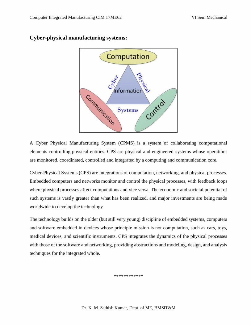
Computer Integrated Manufacturing CIM 17ME62 VI Sem Mechanical
Dr. K. M. Sathish Kumar, Dept. of ME, BMSIT&M
Cyber-physical manufacturing systems:
A Cyber Physical Manufacturing System (CPMS) is a system of collaborating computational
elements controlling physical entities. CPS are physical and engineered systems whose operations
are monitored, coordinated, controlled and integrated by a computing and communication core.
Cyber-Physical Systems (CPS) are integrations of computation, networking, and physical processes.
Embedded computers and networks monitor and control the physical processes, with feedback loops
where physical processes affect computations and vice versa. The economic and societal potential of
such systems is vastly greater than what has been realized, and major investments are being made
worldwide to develop the technology.
The technology builds on the older (but still very young) discipline of embedded systems, computers
and software embedded in devices whose principle mission is not computation, such as cars, toys,
medical devices, and scientific instruments. CPS integrates the dynamics of the physical processes
with those of the software and networking, providing abstractions and modeling, design, and analysis
techniques for the integrated whole.
************
1
Future of Automated Factory
27-08-2020 Dr. K. M. Sathish Kumar, Dept. of ME, BMSIT&M
27-08-2020 2
Industry 4.0 is a name for the current trend
of automation and data exchange in
manufacturing technologies.
It includes cyber physical systems, the Internet
of Things (IoT), Cloud computing and Cognitive
computing.
Industry 4.0 is commonly referred to as the 4th
Industrial revolution.
Industry 4.0 creates what has been called a
"smart factory".
Industry 4.0
Dr. K. M. Sathish Kumar, Dept. of ME, BMSIT&M

27-08-2020 3
The term "Industry 4.0" originates from a project in
the high-tech strategy of the German government.
The term "Industry 4.0" was revived in 2011 at
the Hannover Fair.
In October 2012 the Working Group on Industry 4.0
presented a set of Industry 4.0 implementation
recommendations to the German federal
government.
On 8th April 2013 at the Hannover Fair, the final
report of the Industry 4.0 was presented.Dr. K. M. Sathish Kumar, Dept. of ME, BMSIT&M
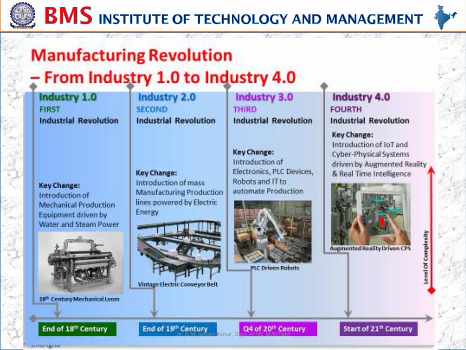
27-08-2020 4Dr. K. M. Sathish Kumar, Dept. of ME, BMSIT&M
27-08-2020 5
• The industrial revolution 4.0 is happening through
the use of cyber-physical systems.
• It means that physical systems such as machines
and robots will be controlled by automation
systems equipped with machine learning
algorithms. Minimal input from human operators
will be needed.
• Industry 4.0 is smart devices turning into smart
products turning into smart factories.
Dr. K. M. Sathish Kumar, Dept. of ME, BMSIT&M
27-08-2020 6
There are four design principles or functions or Features of
Industry 4.0:
Interoperability: where machines, devices, sensors and
people are connected and communicated with each
another.
Information transparency: The transparency afforded by
Industry 4.0 technology provides operators with vast
amounts of useful information needed to make appropriate
decisions. Inter-connectivity allows operators to collect
immense amounts of data and information from all points in
the manufacturing process, thus aiding functionality and
identifying key areas that can benefit from innovation and
improvement.
Functions of Industry 4.0
Dr. K. M. Sathish Kumar, Dept. of ME, BMSIT&M
27-08-2020 7
Technical assistance: First, the ability of assistance
systems to support humans by aggregating and visualizing
information comprehensively for making informed
decisions and solving urgent problems on short notice.
Second, the ability of cyber physical systems to physically
support humans by conducting a range of tasks that are
unpleasant, too exhausting, or unsafe for their human co-
workers.
Decentralized decision: the ability of cyber-physical
systems to make simple decisions on their own and
perform their tasks as autonomously as possible.
Dr. K. M. Sathish Kumar, Dept. of ME, BMSIT&M
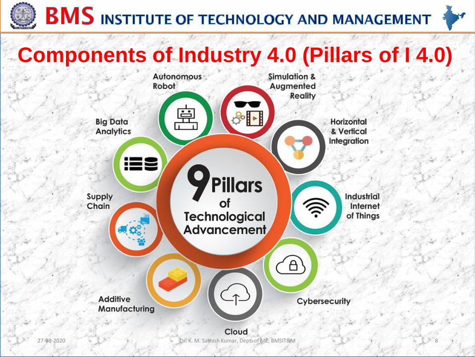
27-08-2020 8
Components of Industry 4.0 (Pillars of I 4.0)
Dr. K. M. Sathish Kumar, Dept. of ME, BMSIT&M
27-08-2020 9
Industrial Internet of Things (IIoT)
The Internet of Things refers to the networking and
connectivity of smart devices.
When you think of IoT, devices such as
smartphones, tablets, and laptops are usually top
of mind.
In the world of manufacturing, this technology is
often referred to as the Industrial Internet of Things
(IIoT).
Manufacturers are attaching sensors to machines
and other physical assets on the plant floor to
collect data which influences decisions real time
and leads to increased efficiency and productivity.Dr. K. M. Sathish Kumar, Dept. of ME, BMSIT&M
27-08-2020 10
Cybersecurity:
Cybersecurity is responsible for providing
protection to the stored information, either on a
device, or on the network.
The system is capable to protect the information
from threats like computer strikes, or even from
physical kind of threats.
Dr. K. M. Sathish Kumar, Dept. of ME, BMSIT&M
27-08-2020 11
Cloud Computing:
With the advent of IoT and Industry 4.0, the reality is
that data is being generated at a staggering speed
and at high volumes, making it impossible to handle
manually. This creates a need for an infrastructure
that can store and manage this data more efficiently.
This is where cloud computing comes in.
Cloud computing offers a platform for users to store
and process vast amounts of data on remote servers.
Dr. K. M. Sathish Kumar, Dept. of ME, BMSIT&M
27-08-2020 12
It enables organisations to use computer
resources without having to develop a computing
infrastructure on premise.
The term cloud computing refers to information
being stored in the “cloud”, accessed remotely
via the Internet.
Dr. K. M. Sathish Kumar, Dept. of ME, BMSIT&M
27-08-2020 13
Big Data Analytics:
The concept of big data applies to large, diverse
and complex datasets that affect the organizational
decision making of a company concerning their
strategy.
Therefore, the increase in level of data and
improvements on technological capabilities
accelerates firms’ competitive advantage by
increasing productivity, innovation and competition.
Dr. K. M. Sathish Kumar, Dept. of ME, BMSIT&M
27-08-2020 14
Autonomous Robots: Robots are used in manufacturing industries in order
to solve complex tasks which cannot be solved
easily by a human.
By the traditional automation strategy, companies
could not fully implement JIT strategies and
continuous improvements if they do not opt for
autonomous robots.
The usage of more industrial robots in factories
accelerates with Industry 4.0.
Robots could be used in several areas such as
production, logistics, distribution activities and could
be controlled remotely by humans thanks to the
human robot cooperation.Dr. K. M. Sathish Kumar, Dept. of ME, BMSIT&M
27-08-2020 15
Additive Manufacturing:
Additive manufacturing, or 3D printing, is a key
technology driving Industry 4.0.
Additive manufacturing is a process of converting
digital 3D models to create parts with a 3D printer
layer by layer.
Within the context of Industry 4.0, 3D printing is
emerging as a valuable digital manufacturing
technology.
AM offers a huge scope of possibilities for
manufacturing from tooling to mass customisation
across virtually all industries.
Dr. K. M. Sathish Kumar, Dept. of ME, BMSIT&M
27-08-2020 16
Augmented Reality:
Augmented reality bridges the gap between the
digital and physical worlds by superimposing
virtual images or data onto a physical object.
For this, the technology uses AR-capable devices,
such as smartphones, tablets and smart glasses.
In the context of manufacturing, AR could enable
workers to speed up the assembly process and
improve decision-making. For example, AR
glasses could be used to project data, such as
layouts, assembly guidelines, sites of possible
malfunction, or a serial number of components, on
the real part, facilitating faster and easier work
procedures. Dr. K. M. Sathish Kumar, Dept. of ME, BMSIT&M
27-08-2020 17
Horizontal and Vertical Integration:
Horizontal integration means every device and
system at the same level of manufacturing in the
same facility or the other is connected with each
other. As this enables communication between
systems in different facilities, jobs can be planned
and adjusted by the machines themselves.
Vertical integration makes it even better. Every
system and humans at all hierarchy has all the
data with required abstraction. Notable challenge
faced in vertical integration is the communication
protocol.Dr. K. M. Sathish Kumar, Dept. of ME, BMSIT&M
27-08-2020 18
Supply Chain:
The manufacturing industry is moving towards a
more digitised, automated, agile and, ultimately,
efficient operation and there is no better
example of this than in the supply chain
network.
In today’s world, the supply chain is a multi-
faceted ecosystem linking product development,
manufacturing and distribution networks into
one fully transparent and digitised system.
Dr. K. M. Sathish Kumar, Dept. of ME, BMSIT&M
27-08-2020 19
Benefits of Industry 4.0
(Advantages of Industry 4.0)
Improved Productivity
Improved Efficiency
Increased Knowledge Sharing And Collaborative Working
Flexibility And Agility
Makes Compliance Easier
Better Customer Experience
Reduces Costs
Creates Innovation Opportunities
Higher Revenues
Increased Profitability
Getting A Return On Investment
Dr. K. M. Sathish Kumar, Dept. of ME, BMSIT&M
27-08-2020 20
Applications of Industry 4.0
Internet of Objects (IoT)
Embedded Software
Big Data and Data Analytics
Machine to Machine Communication (M2M)
Cloud Solutions
Intelligent Robot Automation Systems
Augmented Reality
Simulation
Additive Manufacturing (3D PRINTING)
Cyber Security
Central Monitoring and Control (SCADA)
Mobile Devices
Smart Sensors (RFID, BARCODE)
Smart Objects
Remote control Dr. K. M. Sathish Kumar, Dept. of ME, BMSIT&M
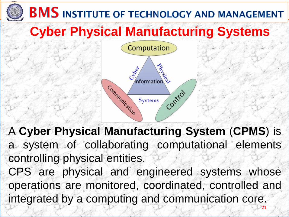
21
A Cyber Physical Manufacturing System (CPMS) is
a system of collaborating computational elements
controlling physical entities.
CPS are physical and engineered systems whose
operations are monitored, coordinated, controlled and
integrated by a computing and communication core.
Cyber Physical Manufacturing Systems
22
• IT security issues
• Reliability and stability needed for critical
machine-to-machine communication (M2M),
including very short and stable latency times
• Need to maintain the integrity of production
processes
• Need to avoid any IT snags, as those would
cause expensive production outages
Challenges in implementation of Industry 4.0
23
• Lack of adequate skill-sets to expedite the
march towards fourth industrial revolution
• General reluctance to change by stakeholders
• Loss of many jobs to automatic processes and
IT-controlled processes, especially for lower
educated parts of society
27-08-2020 24
Internet of Things (IoT) refers to a system of
connected physical objects via the internet.
The ‘thing’ in IoT can refer to a person or any
device which is assigned through an IP address.
A ‘thing’ collects and transfers data over the
internet without any manual intervention with the
help of embedded technology.
It helps them to interact with the external
environment or internal states to take the
decisions.
Internet of Things (IoT)
Dr. K. M. Sathish Kumar, Dept. of ME, BMSIT&M
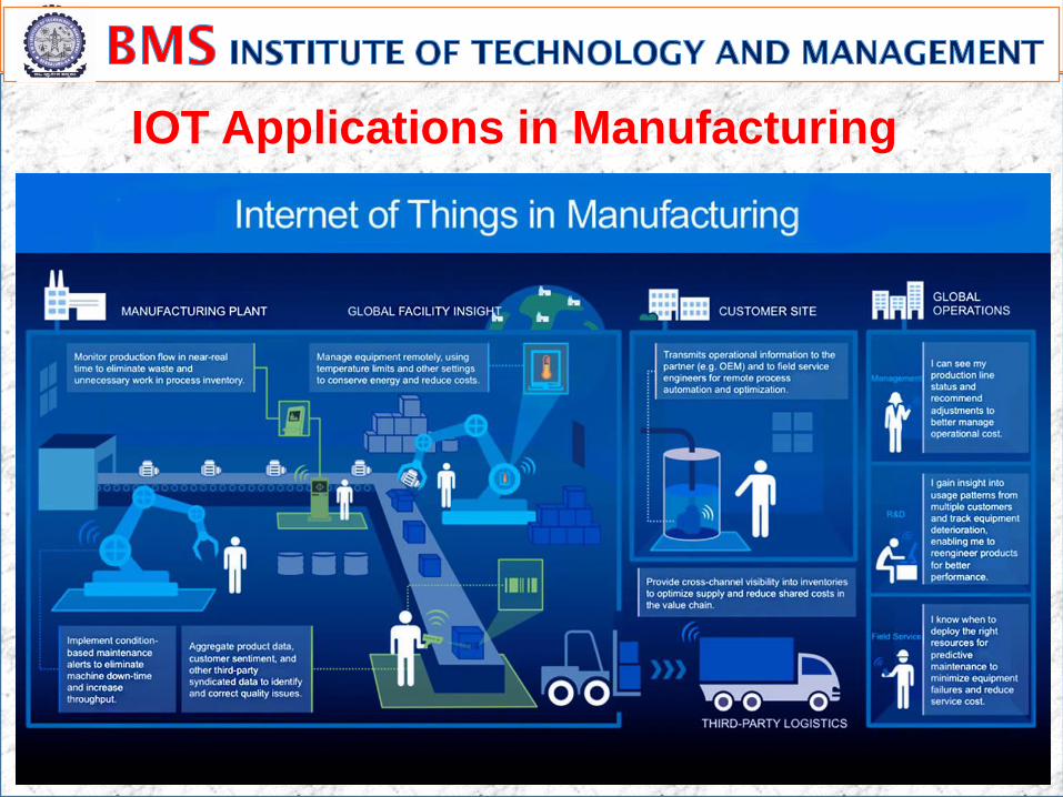
25
IOT Applications in Manufacturing
26
Digital/Connected Factory
Facility Management
Production Flow Monitoring
Inventory Management
Plant Safety and Security
Quality Control
Packaging Optimization
Logistics and Supply Chain Optimization
27
Big-Data and Cloud Computing for IOT
Big Data: Big Data means a large set of
structured, unstructured or semi-structured data
and analyzing those data to get the insights of the
business trend.
Cloud Computing: Cloud Computing gives the
centralized platform to access the data from
anywhere in the world with the shared
infrastructure. Thus, you can save a lot of money.
Cloud computing offers services to users on a
pay-as-you-go model.
28
Cloud providers offer three primary services. These
services are outlined below:
Infrastructure as a Service (IAAS)
The Cloud service provider offers entire infrastructure
along with the maintenance related tasks.
Platform as a Service (PAAS)
The Cloud provider offers resources like object storage,
runtime, queuing, databases, etc. However, the
responsibility of configuration and implementation related
tasks depend on the consumer.
Software as a Service (SAAS)
This service is the most facilitated one which offers all the
necessary settings and infrastructure provided IaaS for
the platform and infrastructure are in place.
29
IoT for smart manufacturing
Smart manufacturing accelerates productivity,
increases efficiency, minimizes delays and
provides a competitive edge for businesses.
Smart manufacturing is enabled by IoT
connected devices, big data, data analytics,
robotics, machine learning, sensor technologies,
and artificial intelligence.
Each of these technologies are used together to
optimize manufacturing processes, assist
manufacturers, and keep workers safe.
30
The potential benefits of smart manufacturing:
Improved employee productivity: Using real-time data from
sensors allows employees to monitor and improve processes
efficiently without delays, which enhances productivity.
Asset optimization: Sensors track assets (machinery,
equipment, tools, trucks, etc.) in real-time, providing visibility of
their potential. On the basis of this data, businesses can make
quick decisions and optimize their asset usage at maximum
capacity.
Reduction of operating costs: Intelligent machines and data
analytics lead to reduced consumption of fuel and electricity,
cuts inefficiencies and decreases overall expenses.
Improved quality of goods: Automation eliminates human
error, and companies are able to produce higher-quality
goods.
31
The study states that worldwide, only 18% of
equipment has failed due to its age, while 82% of
failures occur randomly. It proves that a time-based
approach is not cost-effective.
To avoid ineffective maintenance routine and costs
that accompany it, manufacturers can leverage
Industrial IoT and data science.
An IoT-based predictive maintenance solution can
help to predict potential damage by collecting data
from ultrasonic and vibration sensors attached to the
spindle. Analyzing the collected data helps to identify
fragile spindles before they break.
Influence of IOT on predictive maintenance
32
Next-gen manufacturing equipment uses built-in
sensors and sophisticated programming to perform
predictive analytics and forecast potential issues
before they happen.
Effective predictive maintenance helps to optimize and
streamline maintenance routines in other ways, too.
Predictive analytics often highlights machines or parts
that require constant attention,
33
With new sensor information, IoT can help
manufacturers improve overall equipment
effectiveness (OEE), save money by minimizing
equipment failure, allow the company to perform
planned maintenance, and avoid issues before
they happen.
Predictive maintenance capabilities will alert
operators when a component needs attention or
repair, reducing the need for ongoing inspections.
34
Influence of IOT on Industrial Automation
IoT plus Industrial Automation would get on together
and create IIoT (Industrial IoT).
IIoT networks of smart & intelligent devices allow
organizations to connect their employee every time
wirelessly and manage their activity for their safety on
factory floor.
Some companies are already benefiting from the IIoT
through cost savings due to predictive maintenance,
improved safety, and other operational efficiencies.
The new technology would increase efficiency as well
as work output.
35
Internet of things (IoT) in automation industry is
proving to be a game changer for automation
companies. Industrial automation companies that
use IoT solutions can reap new benefits.
The Internet of Things (IoT) helps to create new
technologies to solve problems, enhance
operations, and increase productivity.
Internet of Things (IoT) Impact on Industrial
Automation is very high and it makes us to use
tablet computers, smart phones, virtualized
systems, and cloud storage of data and so on.
36
Supply Chain Optimization:
IoT enabled systems can be configured for
location tracking, remote health monitoring of
inventory, and reporting of parts and products as
they move through the supply chain.
IoT systems can also collect and feed delivery
information into an ERP system; providing up-to-
date information to accounting functions for
billing.
Real-time information access will help
manufacturers identify issues before they
happen, lower their inventory costs, and
potentially reduce capital requirements.
37
Supply-chain & Logistics
Logistics is just one component of a supply chain.
Logistics has to do with the coordination and
movement of goods. Supply chain involves
multiple facets such as operations and
procurement that keep a company running
smoothly.
Supply chain is the entire flow that brings a
product or service to sale. Logistics is a segment
of that, focused on the transportation and storage
of goods.
38
In the supply chain, Internet of Things devices
are an effective way to track and authenticate
products and shipments using GPS and other
technologies.
They can also monitor the storage conditions
of products which enhances quality
management throughout the supply chain.
39
Thank you
27-08-2020 Dr. K. M. Sathish Kumar, Dept. of ME, BMSIT&M