ixon ultra & life 888 - andor - oxford instruments
TRANSCRIPT

iXon Ultra & Life 888
Hardware GuideCovering the iXon Ultra 888 and iXon Life 888 models
andor.com © Andor Technology Ltd. 2019
Version 1.8 reVised 30 sep 2019
iXon Ultra & Life 888
2Version 1.8 rev 30 Sep 2019
TABLE OF CONTENTS
SECTION 1: INTRODUCTION ............................................................................................................................8
1.1 TECHNICAL SUPPORT ..........................................................................................................................9
1.2 DISCLAIMER .......................................................................................................................................10
1.3 COPYRIGHT AND PROTECTIVE NOTICES .........................................................................................10
1.4 TRADEMARKS AND PATENT INFORMATION .....................................................................................10
1.5 UPDATES TO THIS MANUAL ...............................................................................................................10
1.6 SUPPLIED COMPONENTS ..................................................................................................................11
1.6.1 Optional Components ...........................................................................................................11
1.7 CAMERA POWER SUPPLY UNIT (PSU) ..............................................................................................12
1.7.1 Working with Electronics .......................................................................................................12
1.8 PREVENTION OF CONDENSATION ....................................................................................................13
1.9 EM GAIN AGEING ................................................................................................................................13
1.9.1 Minimizing EM Gain Ageing in your iXon Camera ...............................................................13
1.10 MINIMIZING PARTICULATE CONTAMINATION ..................................................................................14
1.11 SOFTWARE ..........................................................................................................................................14
SECTION 2: PRODUCT OVERVIEW ................................................................................................................15
2.1 IXON ULTRA AND LIFE 888 .................................................................................................................15
2.2 POWER AND SIGNAL CONNECTIONS ...............................................................................................16
2.3 CAMERA LINK (IXON ULTRA ONLY) ...................................................................................................17
2.4 EXTERNAL I/O ......................................................................................................................................18
2.4.1 Additional Cables (iXon Ultra Only) .......................................................................................19
2.5 SIGNAL DIAGRAMS .............................................................................................................................20
2.5.1 iXon Ultra and Life Input & Output Timing Hardware ...........................................................20
2.5.2 External Trigger Input (at connector) ....................................................................................20
SECTION 3: INSTALLING THE IXON ULTRA AND LIFE 888 ..........................................................................21
3.1 PC REQUIREMENTS ............................................................................................................................21
3.2 CONNECTING THE CAMERA ..............................................................................................................21
3.3 COOLING THE CCD .............................................................................................................................22
3.3.1 Sources of Heat Generation ..................................................................................................22
3.3.2 Minimum Achievable Temperatures .....................................................................................23
iXon Ultra & Life 888
3Version 1.8 rev 30 Sep 2019
3.3.3 How to Determine the Minimum Achievable Temperature for your
Specific Acquisition Settings................................................................................................24
3.4 CONNECTING A COOLING SYSTEM .................................................................................................. 25
3.4.1 Hose Connections ................................................................................................................. 25
3.4.2 Coolant Recommendations .................................................................................................. 25
3.4.3 Connecting the Coolant Hoses ............................................................................................. 25
3.4.4 Removing the Coolant Hoses ............................................................................................... 26
3.5 MOUNTING POSTS .............................................................................................................................. 27
3.5.1 Attaching Mounting Posts to the Camera ............................................................................ 27
3.6 INSTALLING ANDOR SOLIS SOFTWARE FOR WINDOWS (8 AND 10) ............................................. 28
3.7 NEW HARDWARE WIZARD ................................................................................................................. 28
3.8 START-UP DIALOG ............................................................................................................................... 28
SECTION 4: TRIGGERING INFORMATION ..................................................................................................... 29
4.1 KEEP CLEAN CYCLES ......................................................................................................................... 29
4.1.1 Idle Keep Clean Cycle ........................................................................................................... 29
4.1.2 Internal Keep Clean Cycle ..................................................................................................... 30
4.1.3 External Keep Clean Cycle .................................................................................................... 31
4.1.4 iXon Series Keep Clean Information ..................................................................................... 32
4.2 TRIGGERING MODES .......................................................................................................................... 33
4.3 TRIGGERING OPTIONS IN FRAME TRANSFER (FT) MODE .............................................................. 34
4.3.1 Internal Triggering .................................................................................................................. 34
4.3.2 External Triggering ................................................................................................................. 35
4.4 TRIGGERING OPTIONS IN NON-FRAME TRANSFER (NFT) MODE .................................................. 37
4.4.1 Internal Triggering (NFT) ........................................................................................................ 37
4.4.2 External & Fast External (NFT) Triggering ............................................................................ 38
4.4.3 External Exposure (NFT) Triggering ...................................................................................... 39
4.4.4 Software (NFT) Triggering ...................................................................................................... 40
4.5 TRIGGERING OPTIONS IN FAST KINETICS (FK) MODE .................................................................... 41
4.5.1 Internal (FK) ............................................................................................................................ 41
4.5.2 External (FK) .......................................................................................................................... 42
4.5.3 External Start (FK) ................................................................................................................. 43
4.6 IXON TRIGGERING DATA .................................................................................................................... 44
4.6.1 iXon Ultra/Life 888 ................................................................................................................. 44
4.6.2 iXon Ultra/Life 897 ................................................................................................................. 44
4.6.3 iXon 3 (DU-897) ...................................................................................................................... 45
iXon Ultra & Life 888
4Version 1.8 rev 30 Sep 2019
4.7 SHUTTERING (IXON ULTRA SERIES ONLY) .......................................................................................45
4.8 ADDITIONAL FUNCTIONALITY ...........................................................................................................46
4.8.1 Count Convert ........................................................................................................................46
4.9 OPTACQUIRE ......................................................................................................................................47
4.9.1 OptAcquire modes .................................................................................................................48
4.10 PUSHING FRAME RATES WITH CROPPED SENSOR MODES .........................................................49
4.10.1 Cropped Sensor Mode Frame Rates ....................................................................................50
4.11 ADVANCED PHOTON COUNTING IN EMCCDS (IXON ULTRA MODELS ONLY) ...............................51
4.11.1 Photon Counting by Post-Processing ..................................................................................53
4.12 SPURIOUS NOISE FILTER ...................................................................................................................54
SECTION 5: TROUBLESHOOTING ..................................................................................................................55
5.1 UNIT DOES NOT SWITCH ON .............................................................................................................55
5.2 SUPPORT DEVICE NOT RECOGNISED WHEN PLUGGED INTO PC ................................................55
5.3 TEMPERATURE TRIP ALARM SOUNDS (CONTINUOUS TONE) .......................................................55
5.4 CAMERA HIGH FIFO FILL ALARM ......................................................................................................56
5.5 USB 3.0 INTER-OPERABILITY ............................................................................................................56
SECTION 6: MAINTENANCE ............................................................................................................................57
6.1 CLEANING CAMERA EXTERIOR .........................................................................................................57
6.2 REGULAR CHECKS .............................................................................................................................57
6.2.1 Annual Electrical Safety Checks ...........................................................................................57
6.3 REPLACEMENT PARTS .......................................................................................................................57
6.4 FUSE REPLACEMENT .........................................................................................................................57
SECTION 7: TECHNICAL SPECIFICATIONS ...................................................................................................58
7.1 IXON ULTRA & LIFE 888 SPECIFICATIONS ........................................................................................58
APPENDIX A: MECHANICAL DRAWINGS ......................................................................................................59
APPENDIX B: DEW POINT GRAPH .................................................................................................................60
APPENDIX C: EMCCD TECHNOLOGY............................................................................................................61
APPENDIX D: GLOSSARY ................................................................................................................................64
APPENDIX E: OTHER INFORMATION .............................................................................................................69

iXon Ultra & Life 888
5Version 1.8 rev 30 Sep 2019
Revision HistoRy
Version Released Description
1.0 27 Mar 2015 Initial Release.
This new hardware guide has been developed from iXon Ultra 897 guide and updated specifically for the Ultra 888 model.
1.1 14 May 2015 Updated Andor Japan Contact details (Section 1.1).
Further detail provided for power supply requirements (Section 1.6)
Removed external exposure for frame transfer mode (Section 4.3)
1.2 25 Jan 2017 Updated presentation (all sections)
Added additional content on cooling (Section 3.4 and Appendix B)
Updated software installation instructions (Sections 3.6, 3.7)
Shuttering information added (Section 4.7)
Additional EMCCD functions added (Section 4.8)
Updated Mechanical Drawings- additional dimensions added (Appendix A)
1.3 04 Jul 2017 Updated to cover the iXon Life 888 model
1.4 29 Nov 2017 Minor edits to align weight, storage temp and clearance specifications across documentation.
Updated software links to Andor website.
1.5 26 Jan 2018 Updated mechanical drawings (Appendix A: water tap connections)
Updated standard supplied items (Packing list, Section 1.6)
1.6 08 Jan 2019 Added section 2.4.1 Additional Cables (iXon Ultra Only) on page 19.
1.7 12 Apr 2019 Updated US and Japan addresses.
1.8 30 Sep 2019 Updated mechanical drawings and China office address and phone number.

iXon Ultra & Life 888
6Version 1.8 rev 30 Sep 2019
safety and WaRning infoRmation
PLEASE READ THIS INFORMATION FIRST
1. To ensure correct and safe operation of this product, please read this guide before use and keep it in a safe place for future reference.
2. If the equipment is used in a manner not specified by Andor, the protection provided by the equipment may be impaired.
3. Before using the system, please follow and adhere to all warnings, safety, manual handling and operating instructions located either on the product or in this guide.
4. This product is a precision scientific instrument containing fragile components. Always handle with care.
5. The camera should be mounted so that the mains supply can be easily disconnected. In case of emergency, the disconnecting device is the mains lead. This will either be the mains lead connected to the product or, in the case of a cabinet-based system, the mains lead to the cabinet.
6. Use only the power supply cord provided with the system for this unit. Should this not be correct for your geographical area contact your local Andor representative.
7. Only the correctly specified mains supply must be used.
8. Make sure the electrical cord is located so that it will not be subject to damage.
9. The product contains components that are extremely sensitive to static electricity and radiated electromagnetic fields, and therefore should not be used, or stored, close to EMI/RFI generators, electrostatic field generators, electromagnetic or radioactive devices, or other similar sources of high energy fields.
10. Operation of the system close to intense pulsed sources (e.g. plasma sources, arc welders, radio frequency generators, X-ray instruments, and pulsed discharge optical sources) may compromise performance if shielding of the Camera is inadequate.
11. This product is not designed to provide protection from ionising radiation. Any customer using this product in such an application should provide their own protection.
12. This product is for use in research laboratories and other controlled scientific environments.
13. This product has not been designed and manufactured for the medical diagnosis of patients.
14. Do not expose the product to extreme hot or cold temperatures.
15. Ensure that the ventilation slots in the camera case are free from blockages.
16. Do not expose the product to open flames.
17. Do not allow objects to fall on the product.
18. Do not expose the product to moisture, wet, or spill liquids on the product. Do not store or place liquids on the product. If spillage occurs on the product, switch off power immediately and wipe off with dry, lint-free cloth. If any ingress has occurred or is suspected, unplug mains cable, do not use, and contact Andor service.
19. There are no user-serviceable parts in the camera. If the head is opened the warranty will be void. Only authorised service personnel may service this equipment.
20. Users must be authorised and trained personnel only; otherwise this may result in personal injury, and/or equipment damage and impaired system performance. Electromagnetic Compatibility: This is a “FCC Class A” product. In a domestic environment this product may cause electromagnetic interference, in which case the user may be required to take adequate measures.

iXon Ultra & Life 888
7Version 1.8 rev 30 Sep 2019
safety and Warning symbols
The following are explanations of the symbols found on this product:
This product has been tested to the requirements of CAN/CSA-C22.2 No. 61010-1, 2nd edition, including Amendment 1, or a later version of the same standard incorporating the same level of testing requirements
The iXon Ultra and Life camera series require a Direct Current (DC) supply.
Refer to this guide before use.
manual Handling
Due to the delicate nature of some of the components within, care must be exercised when handling this product. Proper manual handling techniques are important when unpacking and installing the system to ensure that the integrity of the product is safeguarded and individuals involved are not exposed to unnecessary manual handling risks, such as:
• Lifting a load that is too heavy
• Poor posture or technique during lifting
• Dropping a load
• Lifting objects with sharp edges
sHipping and storage Conditions
Unpacking and Inspection:
• Carefully unpack the unit and retain packaging to return equipment for servicing.
• If the equipment appears damaged in any way, return it to sales outlet in its original packaging. No responsibility for damage arising from the use of non-approved packaging will be accepted.
• Ensure all items and accessories specified in Section 1.5 are present.
If any items are missing, please contact your local sales representative.

8Version 1.8 rev 30 Sep 2019
iXon Ultra & Life 888INTRODUCTION
SECTION 1: INTRODUCTIONThank you for choosing this Andor iXon camera. You are now in possession of a revolutionary new Electron Multiplying Charge Coupled Device (EMCCD), designed for the most challenging low-light imaging applications. This Hardware Guide contains useful information and advice to ensure you get the optimum performance from your new system.

9Version 1.8 rev 30 Sep 2019
iXon Ultra & Life 888INTRODUCTION
1.1 tecHnical suppoRt
If you have any questions regarding the use of this product, please contact the representative* from whom your system was purchased, or:
Europe USAAndor Technology Ltd.
7 Millennium Way
Springvale Business Park
Belfast
BT12 7AL
Northern Ireland
Tel. +44 (0) 28 9023 7126
Fax. +44 (0) 28 9031 0792
Andor Technology
300 Baker Avenue
Suite # 150
Concord
MA 01742
USA
Tel. +1 (860) 290-9211
Fax. +1 (860) 290-9566
Asia-Pacific ChinaAndor Technology (Japan)
5F IS Building
3-32-42 Higashi-Shinagawa
Tokyo 140-0002
Japan
Tel: +81-(0)3-6732-8968
Fax: +81-(0)3-6732-8939
Andor Technology (China)
Haitong Times Business Center,
Building B2 West,
No.11 West Third Ring North Road,
Haidian District,
Beijing,
100089
China
Tel: +86 (0)10 5884 7900
Fax. +86 (0)10 5884 7901
* The latest contact details for your local representative can be found on the contact support page of our website andor.com

10Version 1.8 rev 30 Sep 2019
iXon Ultra & Life 888INTRODUCTION
1.2 disclaimeR
THE INFORMATION CONTAINED HEREIN IS PROVIDED “AS IS” WITHOUT WARRANTY, CONDITION OR REPRESENTATION OF ANY KIND, EITHER EXPRESS, IMPLIED, STATUTORY OR OTHERWISE, INCLUDING BUT NOT LIMITED TO, ANY WARRANTY OF MERCHANTABILITY, NON-INFRINGEMENT OR FITNESS FOR A PARTICULAR PURPOSE.
IN NO EVENT SHALL ANDOR BE LIABLE FOR ANY LOSS OR DAMAGE, WHETHER DIRECT, INDIRECT, SPECIAL, INCIDENTAL, CONSEQUENTIAL OR OTHERWISE HOWSOEVER CAUSED WHETHER ARISING IN CONTRACT, TORT OR OTHERWISE, ARISING OUT OF OR IN CONNECTION WITH THE USE OF THE INFORMATION PROVIDED HEREIN.
1.3 copyRigHt and pRotective notices
The copyright in this document and the associated drawings are the property of Andor Technology Ltd. and all rights are reserved. This document and the associated drawings are issued on condition that they are not copied, reprinted or reproduced, nor their contents disclosed.
The publication of information in this documentation does not imply freedom from any patent or proprietary right of Andor Technology Ltd. or any third party.
1.4 tRademaRks and patent infoRmation
Andor and the Andor logo are trademarks of Andor Technology Ltd. Andor Technology Ltd. is an Oxford Instruments company. All other marks are property of their owners.
1.5 updates to tHis manual
Changes are periodically made to the product and these will be incorporated into new editions of the manual. New versions of all Andor manuals will be made available through MyAndor http://my.andor.com/login.aspx. Please check for the latest information. If you do not have an account please register at http://my.andor.com/Register.aspx.
11Version 1.8 rev 30 Sep 2019
iXon Ultra & Life 888INTRODUCTION
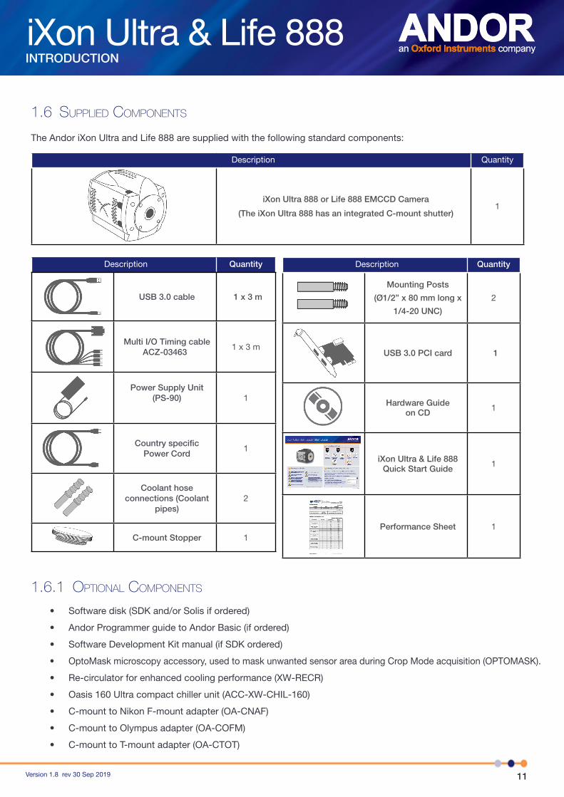
1.6 supplied components
The Andor iXon Ultra and Life 888 are supplied with the following standard components:
Description Quantity
iXon Ultra 888 or Life 888 EMCCD Camera
(The iXon Ultra 888 has an integrated C-mount shutter)1
Description Quantity
USB 3.0 cable 1 x 3 m
Multi I/O Timing cableACZ-03463
1 x 3 m
Power Supply Unit (PS-90) 1
Country specific Power Cord
1
Coolant hose connections (Coolant
pipes)2
C-mount Stopper 1
Description Quantity
Mounting Posts
(Ø1/2” x 80 mm long x
1/4-20 UNC)
2
USB 3.0 PCI card 1
Hardware Guideon CD 1
iXon Ultra & Life 888Quick Start Guide 1
Performance Sheet 1
1.6.1 optional components
• Software disk (SDK and/or Solis if ordered)
• Andor Programmer guide to Andor Basic (if ordered)
• Software Development Kit manual (if SDK ordered)
• OptoMask microscopy accessory, used to mask unwanted sensor area during Crop Mode acquisition (OPTOMASK).
• Re-circulator for enhanced cooling performance (XW-RECR)
• Oasis 160 Ultra compact chiller unit (ACC-XW-CHIL-160)
• C-mount to Nikon F-mount adapter (OA-CNAF)
• C-mount to Olympus adapter (OA-COFM)
• C-mount to T-mount adapter (OA-CTOT)
12Version 1.8 rev 30 Sep 2019
iXon Ultra & Life 888INTRODUCTION
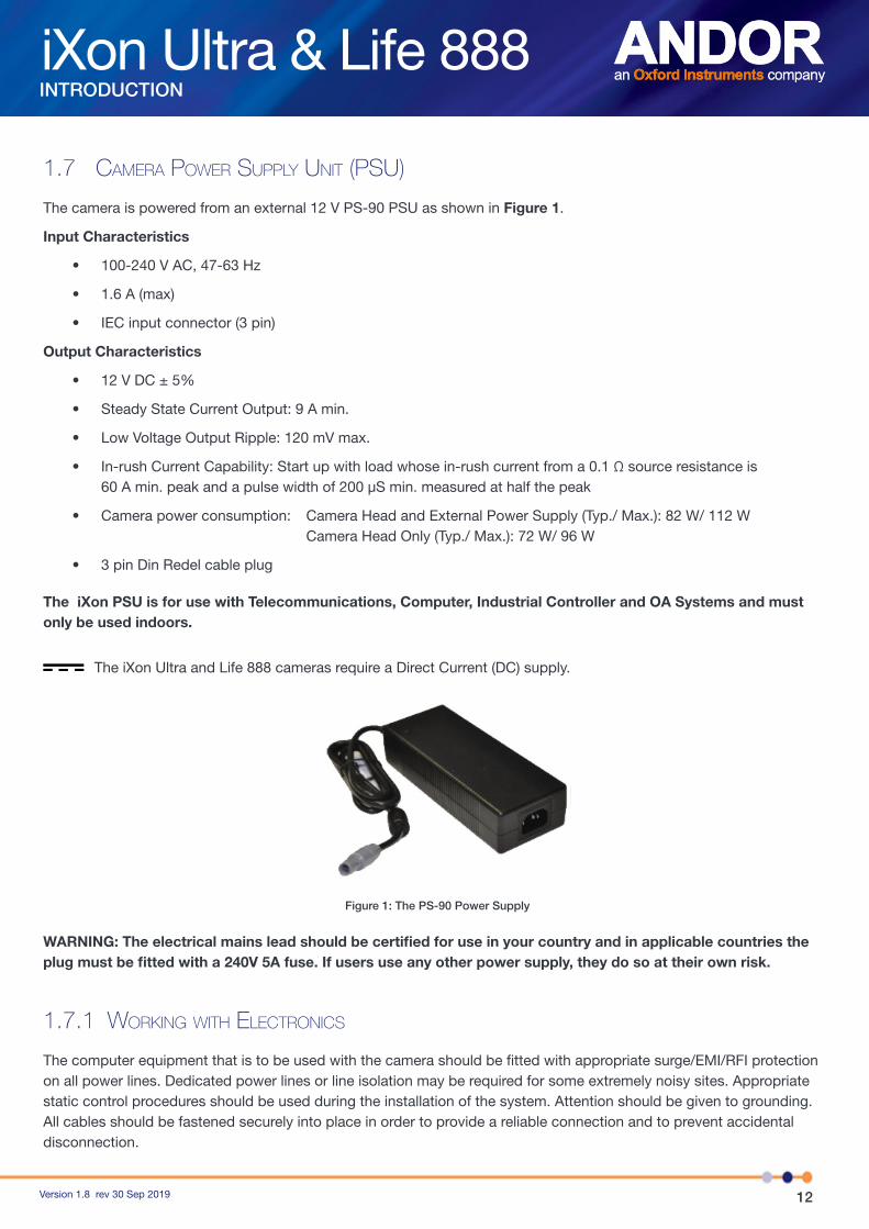
1.7 cameRa poWeR supply unit (psu)
The camera is powered from an external 12 V PS-90 PSU as shown in Figure 1.
Input Characteristics
• 100-240 V AC, 47-63 Hz
• 1.6 A (max)
• IEC input connector (3 pin)
Output Characteristics
• 12 V DC ± 5%
• Steady State Current Output: 9 A min.
• Low Voltage Output Ripple: 120 mV max.
• In-rush Current Capability: Start up with load whose in-rush current from a 0.1 Ω source resistance is 60 A min. peak and a pulse width of 200 μS min. measured at half the peak
• Camera power consumption: Camera Head and External Power Supply (Typ./ Max.): 82 W/ 112 W Camera Head Only (Typ./ Max.): 72 W/ 96 W
• 3 pin Din Redel cable plug
The iXon PSU is for use with Telecommunications, Computer, Industrial Controller and OA Systems and must only be used indoors.
The iXon Ultra and Life 888 cameras require a Direct Current (DC) supply.
Figure 1: The PS-90 Power Supply
WARNING: The electrical mains lead should be certified for use in your country and in applicable countries the plug must be fitted with a 240V 5A fuse. If users use any other power supply, they do so at their own risk.
1.7.1 WoRking WitH electRonics
The computer equipment that is to be used with the camera should be fitted with appropriate surge/EMI/RFI protection on all power lines. Dedicated power lines or line isolation may be required for some extremely noisy sites. Appropriate static control procedures should be used during the installation of the system. Attention should be given to grounding. All cables should be fastened securely into place in order to provide a reliable connection and to prevent accidental disconnection.

13Version 1.8 rev 30 Sep 2019
iXon Ultra & Life 888INTRODUCTION
The circuits used in the camera head are extremely sensitive to static electricity and radiated electromagnetic fields and should not be used (or stored close to) EMI/RFI generators, electrostatic field generators, electromagnetic or radioactive devices, or other similar sources of high energy fields. Types of equipment that can cause problems include Arc welders, Plasma sources, Pulsed-discharge optical sources, Radio frequency generators and X-ray instruments.
1.8 pRevention of condensation
Condensation may form on the outside of the camera body if the temperature of the cooling water is too low or if the water flow is too high. The first signs of condensation will usually be visible around the connectors where the water tubes are attached. In such circumstances switch off the system, disconnect the power supply and carefully wipe the camera with a soft, dry cloth. It is likely there will already be condensation on the cooling block and cooling fins inside the camera. Please also carry out the following actions:
• Set the camera aside to dry for several hours before you attempt re-use
• Before re-use, blow dry gas through the cooling slots on the side of the camera to remove any residual moisture
• Use warmer water or reduce the flow of water when you start using the device again
• Check Dew Point (refer to Appendix B)
1.9 em gain ageing
It has been observed that some EMCCD sensors, more notably in cameras that incorporate L3Vision sensors from e2v, are susceptible to EM Gain fall-off over a period of time. This ageing effect applies to any EMCCD camera manufacturer that incorporates L3Vision sensors into their cameras. The Andor iXon Ultra and Life 888 models use an L3Vision sensor.
A technical note entitled: ‘EMCCD - RealGainTM & EMCALTM’ , which further explains this phenomenon, can be viewed on the Andor website: https://andor.oxinst.com/learning/view/article/realgain,-anti-ageing-emcal
1.9.1 minimizing em gain ageing in youR iXon cameRa
If left unchecked, EM Gain Ageing has the potential to significantly compromise the long-term quantitative reliability of EMCCD cameras. Andor has implemented innovative measures to stabilize the EM Gain on these sensors and ensure the long term quantitative stability to the user. If these guidelines are followed EM Gain Ageing can be minimized and should not present any real problem to the user.
More details of this ageing effect and Andor’s solutions can be found on Section 3.1.7. Some of the guidelines to minimize the EM Gain ageing process are listed below:
• Do not use EM Gain values greater than necessary to overcome the read noise. A gain of x4 or x5 the rms read noise (accessible from the spec sheet or performance sheet) is more than sufficient to render this noise source negligible. In practice, this can be achieved with EM Gain of less than x300 at 10 MHz and x600 for 30MHz operation. Pushing gain beyond this value would give little or no extra Signal to Noise benefit and would only reduce dynamic range.
• Only select the extended EM Gain scale of x1000 for single photon counting applications and always ensure that the signal falling onto the sensor is within the regime of low numbers of photons per pixel.
• Turn down the gain when the camera is not acquiring.
• Try not to over-saturate the EMCCD sensor.

14Version 1.8 rev 30 Sep 2019
iXon Ultra & Life 888INTRODUCTION
1.10 minimizing paRticulate contamination
It is important that particulate contamination of the exterior of the camera window is kept to a minimum, such that images are kept free of ‘shadowing’ particles directly in the optical path. The iXon Ultra range comes equipped with an internal C-mount shutter - this is not present in the iXon Life range. Whilst not being required for frame transfer operation (which is a shutter-free readout mode) it is good practice to close the shutter when the camera is not in acquisition use for a reasonable period. It is also advisable to use the software to close the shutter when exposing the camera to the ‘open environment’ (i.e. removed from a microscope C-mount or focusing lens) whilst power is still flowing to the camera.
When exiting SOLIS the shutter (if fitted) will close automatically. We recommend that the C-mount opening of both the iXon Ultra and Life series is covered when the camera is not in use.
If there is evidence of particulate contamination on the front window it is possible to clean the window by blowing oil free dry air gently over the window surface. To ensure the shutter stays open (Ultra series only), unplug power from the camera when Solis is running and the shutter is open. Exiting Solis abnormally will leave the shutter in the open state.
1.11 softWaRe
The iXon Ultra and Life series can be supplied with Andor Solis, iQ or SDK software. It is also compatible with a range of third party software options that support optimized acquisition control and analysis functionality. For further details of Andor software capabilities and software options, please go to the following page on our website: http://www.andor.com/scientific-software
iXon Ultra & Life 888
15Version 1.8 rev 30 Sep 2019
PRODUCT OVERVIEW
SECTION 2: PRODUCT OVERVIEW
2.1 iXon ultRa and life 888
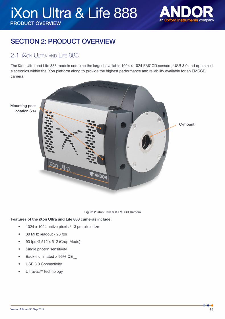
The iXon Ultra and Life 888 models combine the largest available 1024 x 1024 EMCCD sensors, USB 3.0 and optimized electronics within the iXon platform along to provide the highest performance and reliability available for an EMCCD camera.
Figure 2: iXon Ultra 888 EMCCD Camera
Features of the iXon Ultra and Life 888 cameras include:
• 1024 x 1024 active pixels / 13 µm pixel size
• 30 MHz readout - 26 fps
• 93 fps @ 512 x 512 (Crop Mode)
• Single photon sensitivity
• Back-illuminated > 95% QEmax
• USB 3.0 Connectivity
• UltravacTM Technology
C-mount
Mounting postlocation (x4)
iXon Ultra & Life 888
16Version 1.8 rev 30 Sep 2019
PRODUCT OVERVIEW
2.2 poWeR and signal connections
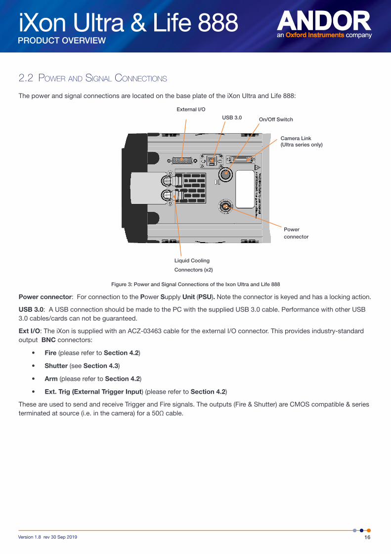
The power and signal connections are located on the base plate of the iXon Ultra and Life 888:
Figure 3: Power and Signal Connections of the Ixon Ultra and Life 888
Power connector: For connection to the Power Supply Unit (PSU). Note the connector is keyed and has a locking action.
USB 3.0: A USB connection should be made to the PC with the supplied USB 3.0 cable. Performance with other USB 3.0 cables/cards can not be guaranteed.
Ext I/O: The iXon is supplied with an ACZ-03463 cable for the external I/O connector. This provides industry-standard output BNC connectors:
• Fire (please refer to Section 4.2)
• Shutter (see Section 4.3)
• Arm (please refer to Section 4.2)
• Ext. Trig (External Trigger Input) (please refer to Section 4.2)
These are used to send and receive Trigger and Fire signals. The outputs (Fire & Shutter) are CMOS compatible & series terminated at source (i.e. in the camera) for a 50Ω cable.
Power connector
Camera Link(Ultra series only)
On/Off SwitchUSB 3.0
External I/O
Liquid Cooling
Connectors (x2)
iXon Ultra & Life 888
17Version 1.8 rev 30 Sep 2019
PRODUCT OVERVIEW
NOTES:
1. The cable termination at the customer end should be high impedance (>1KΩ) as an incorrect impedance match could cause errors with timing and triggering.
2. The External Trigger Input is TTL level, CMOS compatible and has >10KΩ impedance.
3. Signal diagrams of these connections are shown on Section 2.4. The interfaces and internal circuits of the iXon Ultra and Life series are rated as SELV (Safety Extra Low Voltage). All interfacing equipment should use SELV voltage and current levels.
5. OutputDAC1 and OutputDAC2 (iXon Ultra only) are 16-bit DAC outputs that can be configured by the user to be up to approximately 10.1 Volts. Maximum output current that can be drawn is 10mA
6. +5V Output is a 5V supply to signal to the user that the camera is powered up. The maximum current that can be drawn from this is 500mA
7. I/O bits (8 off) (iXon Ultra only) are user programmable and can either be inputs or outputs. When being used as inputs these default to being weakly pulled high. The maximum low level input voltage is 1.5V and the minimum high level input voltage is 3.5V. As outputs the maximum “high” level output current that can be drawn is 0.03mA and the maximum “low” level current that each output can sink is 10mA.
I2C: I2C connection point- 2 x16-bit DACs, and 8 digital i/os available on the External I/O (iXon Ultra only). Access to these connections requires an advanced cable (ACZ-03453) to connect to the 26 way High density D connector. See section 2.4.1 for more information on optional cables.
2.3 cameRa link (iXon ultRa only)
The iXon Ultra is equipped with a Base Configuration (3-tap interface) Camera Link output which conforms to the specification defined by the Automated Imaging Association (AIA). This provides access to the camera data output with very low latency. Note that this is an OUTPUT ONLY e.g for use with a Camera Link frame grabber or custom embedded applications.
A Technical Note “Camera Link Output” is available at: https://www.oxinst.com/learning/view/article/camera-link-output
iXon Ultra & Life 888
18Version 1.8 rev 30 Sep 2019
PRODUCT OVERVIEW
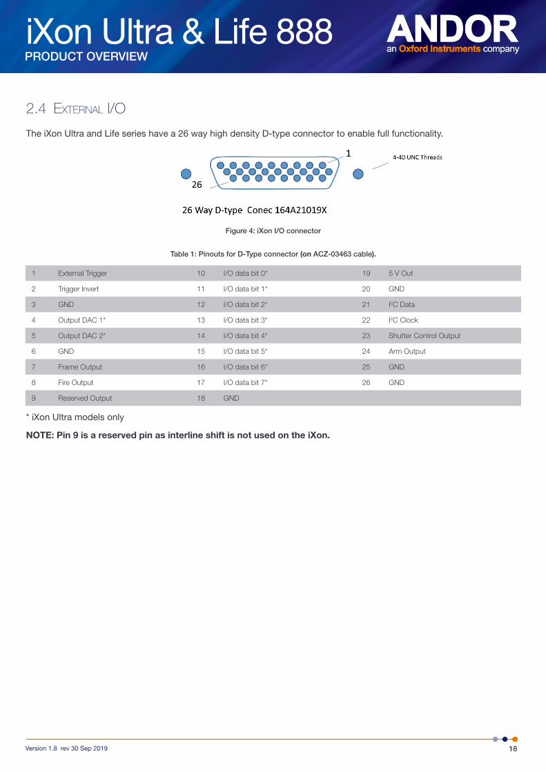
2.4 eXteRnal i/o
The iXon Ultra and Life series have a 26 way high density D-type connector to enable full functionality.
Figure 4: iXon I/O connector
Table 1: Pinouts for D-Type connector (on ACZ-03463 cable).
1 External Trigger 10 I/O data bit 0* 19 5 V Out
2 Trigger Invert 11 I/O data bit 1* 20 GND
3 GND 12 I/O data bit 2* 21 I2C Data
4 Output DAC 1* 13 I/O data bit 3* 22 I2C Clock
5 Output DAC 2* 14 I/O data bit 4* 23 Shutter Control Output
6 GND 15 I/O data bit 5* 24 Arm Output
7 Frame Output 16 I/O data bit 6* 25 GND
8 Fire Output 17 I/O data bit 7* 26 GND
9 Reserved Output 18 GND
* iXon Ultra models only
NOTE: Pin 9 is a reserved pin as interline shift is not used on the iXon.
iXon Ultra & Life 888
19Version 1.8 rev 30 Sep 2019
PRODUCT OVERVIEW
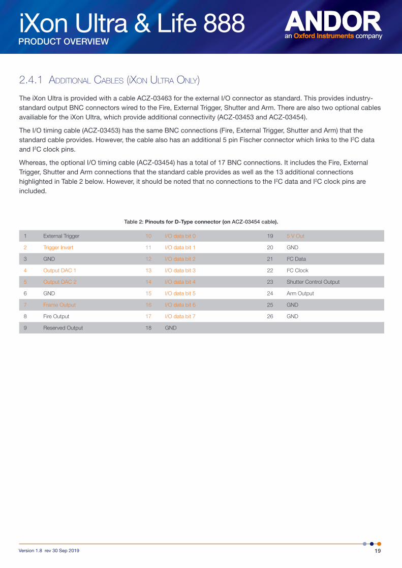
2.4.1 additional cables (iXon ultRa only)
The iXon Ultra is provided with a cable ACZ-03463 for the external I/O connector as standard. This provides industry-standard output BNC connectors wired to the Fire, External Trigger, Shutter and Arm. There are also two optional cables availiable for the iXon Ultra, which provide additional connectivity (ACZ-03453 and ACZ-03454).
The I/O timing cable (ACZ-03453) has the same BNC connections (Fire, External Trigger, Shutter and Arm) that the standard cable provides. However, the cable also has an additional 5 pin Fischer connector which links to the I2C data and I2C clock pins.
Whereas, the optional I/O timing cable (ACZ-03454) has a total of 17 BNC connections. It includes the Fire, External Trigger, Shutter and Arm connections that the standard cable provides as well as the 13 additional connections highlighted in Table 2 below. However, it should be noted that no connections to the I2C data and I2C clock pins are included.
Table 2: Pinouts for D-Type connector (on ACZ-03454 cable).
1 External Trigger 10 I/O data bit 0 19 5 V Out
2 Trigger Invert 11 I/O data bit 1 20 GND
3 GND 12 I/O data bit 2 21 I2C Data
4 Output DAC 1 13 I/O data bit 3 22 I2C Clock
5 Output DAC 2 14 I/O data bit 4 23 Shutter Control Output
6 GND 15 I/O data bit 5 24 Arm Output
7 Frame Output 16 I/O data bit 6 25 GND
8 Fire Output 17 I/O data bit 7 26 GND
9 Reserved Output 18 GND
iXon Ultra & Life 888
20Version 1.8 rev 30 Sep 2019
PRODUCT OVERVIEW
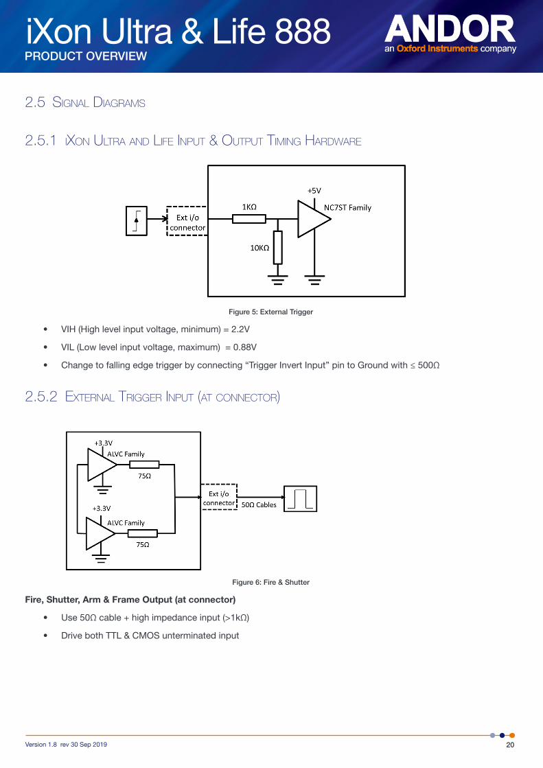
2.5 signal diagRams
2.5.1 iXon ultRa and life input & output timing HaRdWaRe
Figure 5: External Trigger
• VIH (High level input voltage, minimum) = 2.2V
• VIL (Low level input voltage, maximum) = 0.88V
• Change to falling edge trigger by connecting “Trigger Invert Input” pin to Ground with ≤ 500Ω
2.5.2 eXteRnal tRiggeR input (at connectoR)
Figure 6: Fire & Shutter
Fire, Shutter, Arm & Frame Output (at connector)
• Use 50Ω cable + high impedance input (>1kΩ)
• Drive both TTL & CMOS unterminated input

iXon Ultra & Life 888
21Version 1.8 rev 30 Sep 2019
INSTALLATION
SECTION 3: INSTALLING THE IXON ULTRA AND LIFE 888
3.1 pc RequiRements
Install the camera software before first connecting the camera – this will ensure that USB drivers are available when required.
There are no restrictions on the order in which components are connected. It is best to allow a few seconds from camera power on (using either the button or a mains switch) to starting Solis in order for the camera to be recognised by the PC.
• 3 GHz Quad Core or 2.6 GHz multi core processor
• 2 GB RAM
• 100 MB free hard disc to install software (at least 1 GB recommended for data spooling)
• Solid-state drive (SSD) capable of a minimum sustained write speed of 100MB/S for spooling data• USB 3.0 Super Speed Host Controller capable of sustained rate of 60MB/s
• Windows (8 and 10) or Linux
3.2 connecting tHe cameRa
1. Attach the camera to lens or optical system using the camera C-mount interface as required
2. Insert the 12V DC power cable from the PS-90 power supply into the power connector on the bottom plate of the camera, ensure the orientation is correct. NEVER forcibly insert the connector.
3. Connect the supplied USB 3.0 cable between the USB 3.0 connector on the camera and the corresponding slot on the PC. (A USB socket on the rear of a desktop machine is preferred). Only use USB 3.0 cables supplied by Andor as performance can not be assured with other models.
4. Switch the camera ON using the ON/OFF switch. You should hear an audible confirmation (camera start-up tone).
Note: The iXon Ultra and Life series have a power switch on the camera head for convenience.
5. The supplied Multi i/o cable may be required depending on the measurement being carried out. Refer to Section 2.4 for details.
6. The camera can achieve stated performance with air cooling using the internal fan – Water cooling is also available see Section 3.3 for details.
iXon Ultra & Life 888
22Version 1.8 rev 30 Sep 2019
INSTALLATION
3.3 cooling tHe ccd
Heat is generated by the sensor during normal operation which if not addressed may have a significant adverse effect on performance (e.g. signal to noise ratio and sensitivity) due to increased dark current noise. The iXon range makes use of a multi-stage (3: iXon Life; 4 iXon Ultra) Peltier cooling assembly (thermoelectric cooler, TEC), which utilizes the thermoelectric effect to rapidly cool the sensor down to the stable operating temperature. A TEC has a cold side (in contact with the sensor) and a hot side. Temperature control components regulate the cooling of the camera and ensure that a stable temperature is maintained between and throughout measurements.
The iXon Ultra and Life models can use either forced air cooling- using the in-built fan, or water cooling for enhanced cooling performance (refer to Section 3.4 for connection information). When using water cooling, a re-circulator or a chiller can be purchased from Andor to provide a convenient and effective heat dissipation.
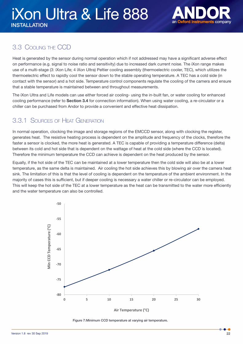
3.3.1 souRces of Heat geneRation
In normal operation, clocking the image and storage regions of the EMCCD sensor, along with clocking the register, generates heat. The resistive heating process is dependent on the amplitude and frequency of the clocks, therefore the faster a sensor is clocked, the more heat is generated. A TEC is capable of providing a temperature difference (delta) between its cold and hot side that is dependent on the wattage of heat at the cold side (where the CCD is located). Therefore the minimum temperature the CCD can achieve is dependent on the heat produced by the sensor.
Equally, if the hot side of the TEC can be maintained at a lower temperature then the cold side will also be at a lower temperature, as the same delta is maintained. Air cooling the hot side achieves this by blowing air over the camera heat sink. The limitation of this is that the level of cooling is dependent on the temperature of the ambient environment. In the majority of cases this is sufficient, but if deeper cooling is necessary a water chiller or re-circulator can be employed. This will keep the hot side of the TEC at a lower temperature as the heat can be transmitted to the water more efficiently and the water temperature can also be controlled.
-80
-75
-70
-65
-60
-55
-50
0 5 10 15 20 25 30
Min
CCD
Tem
pera
ture
(°C)
Air Temperature (°C)
Figure 7: Minimum CCD temperature at varying air temperature.
iXon Ultra & Life 888
23Version 1.8 rev 30 Sep 2019
INSTALLATION
3.3.2 Minimum acHievable tempeRatuRes
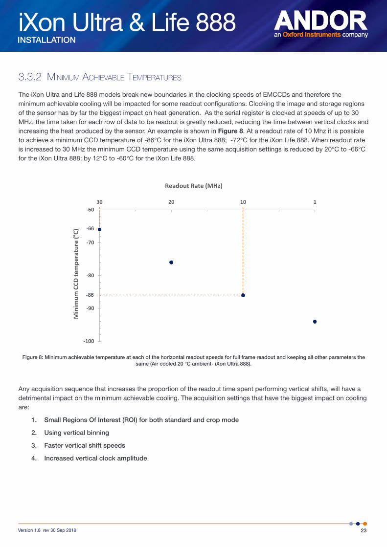
The iXon Ultra and Life 888 models break new boundaries in the clocking speeds of EMCCDs and therefore the minimum achievable cooling will be impacted for some readout configurations. Clocking the image and storage regions of the sensor has by far the biggest impact on heat generation. As the serial register is clocked at speeds of up to 30 MHz, the time taken for each row of data to be readout is greatly reduced, reducing the time between vertical clocks and increasing the heat produced by the sensor. An example is shown in Figure 8. At a readout rate of 10 Mhz it is possible to achieve a minimum CCD temperature of -86°C for the iXon Ultra 888; -72°C for the iXon Life 888. When readout rate is increased to 30 MHz the minimum CCD temperature using the same acquisition settings is reduced by 20°C to -66°C for the iXon Ultra 888; by 12°C to -60°C for the iXon Life 888.
Figure 8: Minimum achievable temperature at each of the horizontal readout speeds for full frame readout and keeping all other parameters the same (Air cooled 20 °C ambient- iXon Ultra 888).
Any acquisition sequence that increases the proportion of the readout time spent performing vertical shifts, will have a detrimental impact on the minimum achievable cooling. The acquisition settings that have the biggest impact on cooling are:
1. Small Regions Of Interest (ROI) for both standard and crop mode
2. Using vertical binning
3. Faster vertical shift speeds
4. Increased vertical clock amplitude
-100
-90
-80
-70
-6030 20 10 1
Min
imum
CCD
tem
pera
ture
(°C)
Readout Rate (MHz)
-66
-86
iXon Ultra & Life 888
24Version 1.8 rev 30 Sep 2019
INSTALLATION
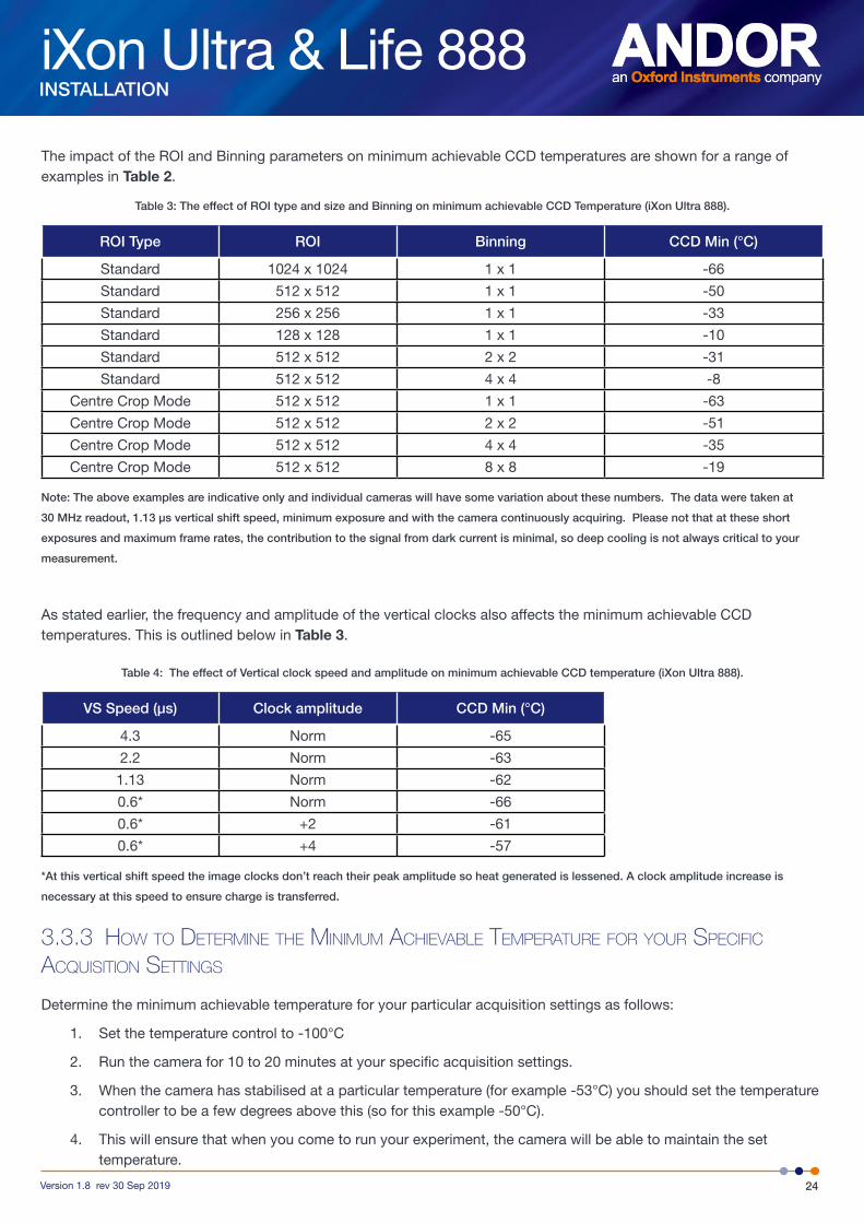
The impact of the ROI and Binning parameters on minimum achievable CCD temperatures are shown for a range of examples in Table 2.
Table 3: The effect of ROI type and size and Binning on minimum achievable CCD Temperature (iXon Ultra 888).
ROI Type ROI Binning CCD Min (°C)
Standard 1024 x 1024 1 x 1 -66
Standard 512 x 512 1 x 1 -50
Standard 256 x 256 1 x 1 -33
Standard 128 x 128 1 x 1 -10
Standard 512 x 512 2 x 2 -31
Standard 512 x 512 4 x 4 -8
Centre Crop Mode 512 x 512 1 x 1 -63
Centre Crop Mode 512 x 512 2 x 2 -51
Centre Crop Mode 512 x 512 4 x 4 -35
Centre Crop Mode 512 x 512 8 x 8 -19
Note: The above examples are indicative only and individual cameras will have some variation about these numbers. The data were taken at
30 MHz readout, 1.13 µs vertical shift speed, minimum exposure and with the camera continuously acquiring. Please not that at these short
exposures and maximum frame rates, the contribution to the signal from dark current is minimal, so deep cooling is not always critical to your
measurement.
As stated earlier, the frequency and amplitude of the vertical clocks also affects the minimum achievable CCD temperatures. This is outlined below in Table 3.
Table 4: The effect of Vertical clock speed and amplitude on minimum achievable CCD temperature (iXon Ultra 888).
VS Speed (µs) Clock amplitude CCD Min (°C)
4.3 Norm -65
2.2 Norm -63
1.13 Norm -62
0.6* Norm -66
0.6* +2 -61
0.6* +4 -57
*At this vertical shift speed the image clocks don’t reach their peak amplitude so heat generated is lessened. A clock amplitude increase is
necessary at this speed to ensure charge is transferred.
3.3.3 HoW to deteRmine tHe minimum acHievable tempeRatuRe foR youR specific acquisition settings
Determine the minimum achievable temperature for your particular acquisition settings as follows:
1. Set the temperature control to -100°C
2. Run the camera for 10 to 20 minutes at your specific acquisition settings.
3. When the camera has stabilised at a particular temperature (for example -53°C) you should set the temperature controller to be a few degrees above this (so for this example -50°C).
4. This will ensure that when you come to run your experiment, the camera will be able to maintain the set temperature.

iXon Ultra & Life 888
25Version 1.8 rev 30 Sep 2019
INSTALLATION
3.4 Connecting a cooling system
3.4.1 Hose connections
Two barbed coolant hose inserts are supplied as standard with the iXon Ultra and Life cameras, suitable for connection to 6 mm (0.25”) internal diameter soft PVC tubing / hose.
Recommended tubing: 10 mm (0.4”) outside diameter, i.e. a wall thickness of 2 mm (0.08”).
Alternative hose dimensions and materials should be thoroughly tested to ensure a leak tight seal is achieved with the barbed inserts.
3.4.2 coolant Recommendations
Is recommended that de-ionized water (without additives) is used as the coolant to prevent deposits forming. Some mains supply water is heavily mineralized (i.e. “Hard”) which could cause deposits in the water circuit inside the camera. This can reduce the flow-rate, and therefore, the cooling efficiency.
The specified cooling performance of the camera can be achieved with coolant flow rates of >0.75 litres per minute, the maximum recommended pressure of coolant circulating through the camera head is 2 bar (30 PSI).
In the event that replacement hose inserts / barbs are required, please contact your local Andor representative.
CAUTION: Always ensure that the temperature of the liquid coolant circulated through the camera head is above the dew point of the camera ambient. Use of coolant at or below the dew point will result in permanent damage to the camera head, due to formation of condensation on internal components (refer to Appendix B).
3.4.3 connecting tHe coolant Hoses
1. Press the hose insert into the coolant hose, and repeat for the second hose.
2. Press the hose connectors into the connections on the camera head, ensure they click into place.
3. Confirm the hoses are connected securely by applying pressure on the front of the camera body and pulling backwards on each hose.
Figure 9: Hose inserts and quick release coupling

iXon Ultra & Life 888
26Version 1.8 rev 30 Sep 2019
INSTALLATION
4. Connect the other ends of the coolant hoses to the cooling system- refer to the cooling system manual.
3.4.4 Removing tHe coolant Hoses
CAUTION: Before attempting to remove the hose connections, ensure that all water has been drained from the hoses and the coolant channel within the camera head. Care must be taken to avoid permanent damage to the camera system resulting from either leakage of coolant during connection/removal of hoses or spillage of any residual coolant contained within the camera head once the hoses have been removed.
1. Press the latch on the camera hose connection away from the hose.
2. Hold the latch in and pull the hose backwards.
3. The hose should release from the camera connection with little resistance.
NOTE: If the hose does not release, ensure that the latch on the camera connection is pressed in fully.

iXon Ultra & Life 888
27Version 1.8 rev 30 Sep 2019
INSTALLATION
3.5 mounting posts
There are 4 pairs of mounting post positions on all four sides of the camera. These can be used to mount the camera if the C-Mount is not used, or to mount accessories. Each pair of holes has a 2.0” spacing.
NOTE: A bag containing two Ø1/2” x 80 mm long x 1/4-20 UNC posts is included with all kits
Figure 10: Attaching the Mounting Posts
3.5.1 attacHing mounting posts to tHe cameRa
1. Carefully remove the black grommet(s) as shown in Figure 10.
2. Screw each mounting post into the exposed mounting hole
3. Tighten using a screwdriver shank through the hole in the mounting post
NOTE: Store the blanking grommets so they may re-installed if the mounting posts are not in use.
iXon Ultra & Life 888
28Version 1.8 rev 30 Sep 2019
INSTALLATION
3.6 installing andoR solis softWaRe foR WindoWs (8 and 10)
1. Terminate & exit any applications which are running on the PC.
2. Insert the Andor Solis CD. The InstallShield Wizard should now start. If it does not start automatically, run the setup.exe file directly from the CD.
3. Select appropriate location for installation of software and drivers on your computer / network.
4. If prompted, select iXon Ultra/iXon Life.
5. Continue installation and restart your computer - when prompted - to successfully complete the installation.
6. The shortcut icon for Solis will appear on the desktop on re-start.
7. The iXon Camera is now ready to be connected to a PC / laptop and powered on.
3.7 neW HaRdWaRe WizaRd
When the iXon camera is connected to a PC for the first time, the New Hardware Wizard screen will appear.
1. Select the ‘No, not this time only’ option then click Next>.
2. Select the ‘Install from a list or specified location (Advanced) option then click Next>.
3. Navigate to the directory where the Andor Solis software was installed to on the PC, then click Next> so that the Installation Wizard can start.
4. Click the Finish button to complete the installation.
Note: If the camera is connected to a different USB port, steps 1 – 4 will have to be repeated on the first connection only.
5. A system message will appear to indicate that the device has been successfully installed.
Note: You can check that the iXon camera is correctly recognized and installed by opening the Device Manager (Devices and printers) in Windows, Control Panel. The iXon camera will show under the Devices list.
NOTE: On the first startup of Solis, you may be required to direct the software to the iXon Ultra/iXon Life drivers. If so, select the directory that Andor Solis was installed to.
3.8 staRt-up dialog
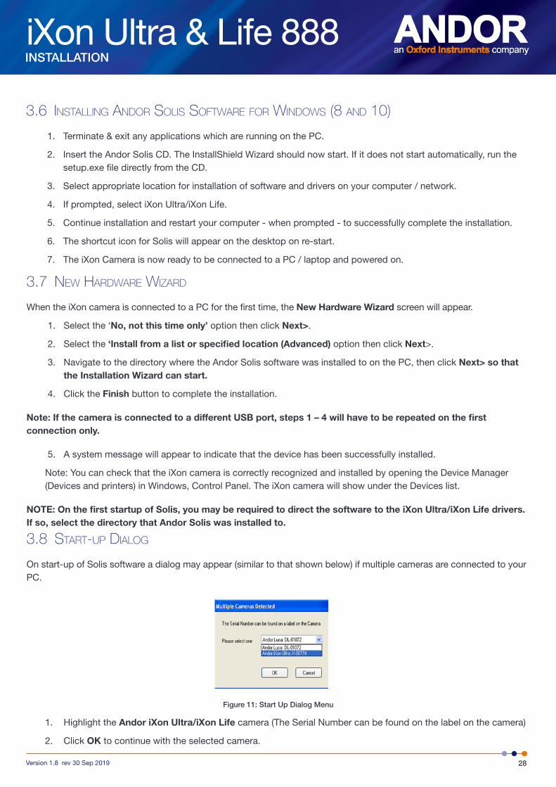
On start-up of Solis software a dialog may appear (similar to that shown below) if multiple cameras are connected to your PC.
Figure 11: Start Up Dialog Menu
1. Highlight the Andor iXon Ultra/iXon Life camera (The Serial Number can be found on the label on the camera)
2. Click OK to continue with the selected camera.
iXon Ultra & Life 888
29Version 1.8 rev 30 Sep 2019
INSTALLATION
SECTION 4: TRIGGERING INFORMATIONThis section describes the Keep Clean Cycles and Triggering modes for the iXon Ultra 888 and Life 888 models.
4.1 keep clean cycles
iXon Ultra and Life cameras have a range of different Keep Clean Cycles that run depending on the actual model and the state the camera is in. The first Keep Clean Cycle runs while the camera is in an idle state, i.e. waiting for the PC to tell it to start an acquisition sequence. The next Keep Clean Cycle runs during an internal trigger kinetics series sequence. The final Keep Clean Cycle runs while the camera is waiting for an external trigger event to occur.
4.1.1 idle keep clean cycle
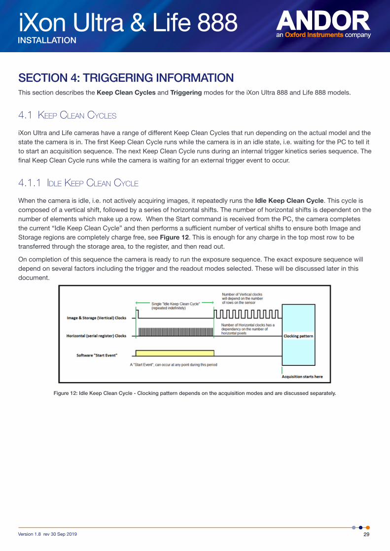
When the camera is idle, i.e. not actively acquiring images, it repeatedly runs the Idle Keep Clean Cycle. This cycle is composed of a vertical shift, followed by a series of horizontal shifts. The number of horizontal shifts is dependent on the number of elements which make up a row. When the Start command is received from the PC, the camera completes the current “Idle Keep Clean Cycle” and then performs a sufficient number of vertical shifts to ensure both Image and Storage regions are completely charge free, see Figure 12. This is enough for any charge in the top most row to be transferred through the storage area, to the register, and then read out.
On completion of this sequence the camera is ready to run the exposure sequence. The exact exposure sequence will depend on several factors including the trigger and the readout modes selected. These will be discussed later in this document.
Figure 12: Idle Keep Clean Cycle - Clocking pattern depends on the acquisition modes and are discussed separately.
iXon Ultra & Life 888
30Version 1.8 rev 30 Sep 2019
TRIGGERING INFORMATION
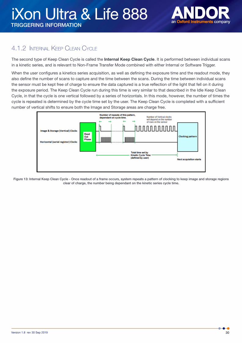
4.1.2 inteRnal keep clean cycle
The second type of Keep Clean Cycle is called the Internal Keep Clean Cycle. It is performed between individual scans in a kinetic series, and is relevant to Non-Frame Transfer Mode combined with either Internal or Software Trigger.
When the user configures a kinetics series acquisition, as well as defining the exposure time and the readout mode, they also define the number of scans to capture and the time between the scans. During the time between individual scans the sensor must be kept free of charge to ensure the data captured is a true reflection of the light that fell on it during the exposure period. The Keep Clean Cycle run during this time is very similar to that described in the Idle Keep Clean Cycle, in that the cycle is one vertical followed by a series of horizontals. In this mode, however, the number of times the cycle is repeated is determined by the cycle time set by the user. The Keep Clean Cycle is completed with a sufficient number of vertical shifts to ensure both the Image and Storage areas are charge free.
Figure 13: Internal Keep Clean Cycle - Once readout of a frame occurs, system repeats a pattern of clocking to keep image and storage regions clear of charge, the number being dependant on the kinetic series cycle time.
iXon Ultra & Life 888
31Version 1.8 rev 30 Sep 2019
TRIGGERING INFORMATION
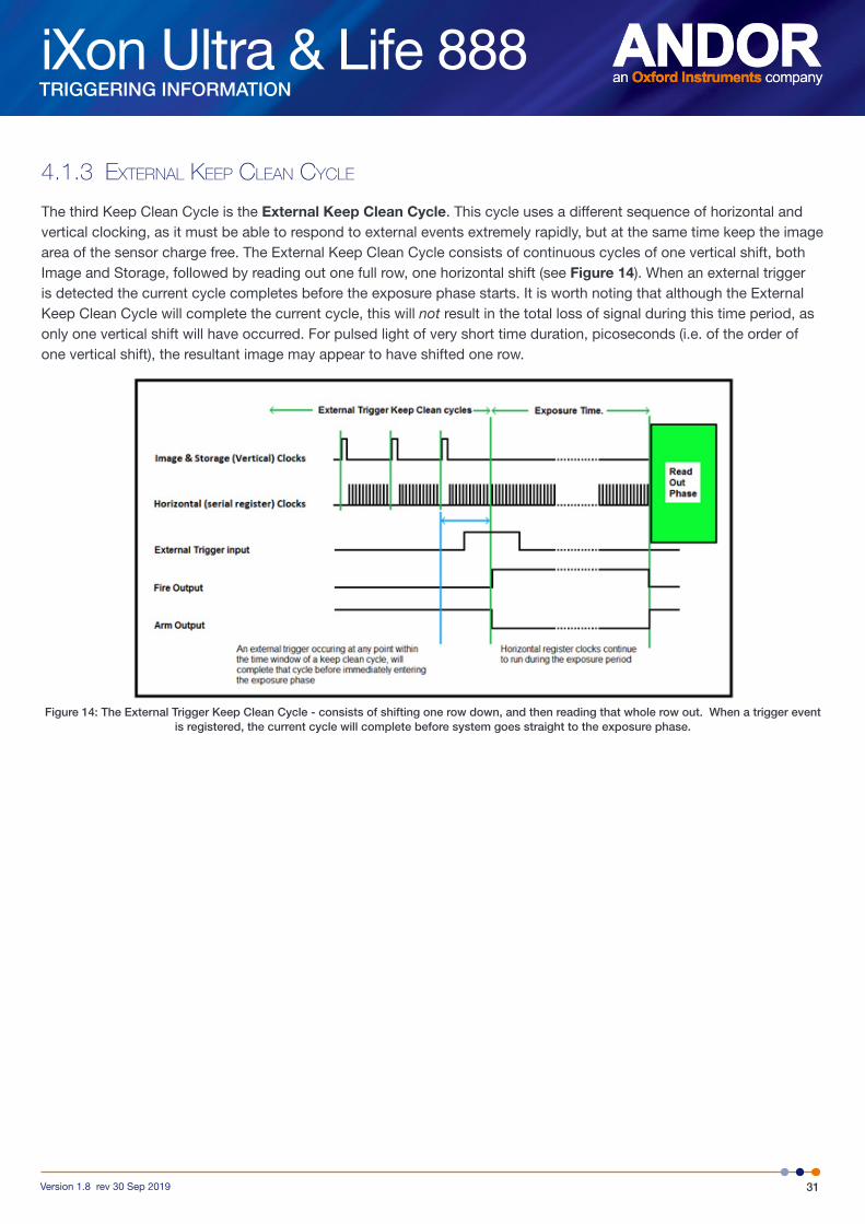
4.1.3 eXteRnal keep clean cycle
The third Keep Clean Cycle is the External Keep Clean Cycle. This cycle uses a different sequence of horizontal and vertical clocking, as it must be able to respond to external events extremely rapidly, but at the same time keep the image area of the sensor charge free. The External Keep Clean Cycle consists of continuous cycles of one vertical shift, both Image and Storage, followed by reading out one full row, one horizontal shift (see Figure 14). When an external trigger is detected the current cycle completes before the exposure phase starts. It is worth noting that although the External Keep Clean Cycle will complete the current cycle, this will not result in the total loss of signal during this time period, as only one vertical shift will have occurred. For pulsed light of very short time duration, picoseconds (i.e. of the order of one vertical shift), the resultant image may appear to have shifted one row.
Figure 14: The External Trigger Keep Clean Cycle - consists of shifting one row down, and then reading that whole row out. When a trigger event is registered, the current cycle will complete before system goes straight to the exposure phase.
iXon Ultra & Life 888
32Version 1.8 rev 30 Sep 2019
TRIGGERING INFORMATION
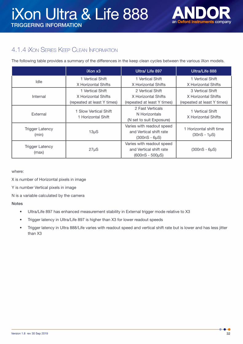
4.1.4 iXon seRies keep clean infoRmation
The following table provides a summary of the differences in the keep clean cycles between the various iXon models.
iXon x3 Ultra/ Life 897 Ultra/Life 888
Idle1 Vertical Shift
X Horizontal Shifts1 Vertical Shift
X Horizontal Shifts1 Vertical Shift
X Horizontal Shifts
Internal1 Vertical Shift
X Horizontal Shifts (repeated at least Y times)
2 Vertical Shift X Horizontal Shifts
(repeated at least Y times)
3 Vertical Shift X Horizontal Shifts
(repeated at least Y times)
External1 Slow Vertical Shift
1 Horizontal Shift
2 Fast Verticals N Horizontals
(N set to suit Exposure)
1 Vertical Shift X Horizontal Shifts
Trigger Latency (min)
13µSVaries with readout speed
and Vertical shift rate (300nS - 6µS)
1 Horizontal shift time (30nS - 1µS)
Trigger Latency (max)
27µSVaries with readout speed
and Vertical shift rate (600nS - 500µS)
(300nS - 6µS)
where:
X is number of Horizontal pixels in image
Y is number Vertical pixels in image
N is a variable calculated by the camera
Notes
• Ultra/Life 897 has enhanced measurement stability in External trigger mode relative to X3
• Trigger latency in Ultra/Life 897 is higher than X3 for lower readout speeds
• Trigger latency in Ultra 888/Life varies with readout speed and vertical shift rate but is lower and has less jitter than X3
iXon Ultra & Life 888
33Version 1.8 rev 30 Sep 2019
TRIGGERING INFORMATION
4.2 tRiggeRing modes
The iXon Ultra and Life camera series have several different triggering modes. These include Internal, External (and Fast External), External Start, External Exposure and Software Trigger. Note also that many of these features require iCam technology within the camera, fuller details of which can be viewed through www.andor.com
• In Internal Trigger the camera determines the exact time when an exposure happens, based on the acquisition settings entered by the user. This is the most basic trigger mode and requires no external intervention.
• In External Trigger, once an acquisition starts, the camera is placed into “External Keep Clean Cycle”, which ensures that charge built up on the CCD is kept to a minimum while waiting for the external trigger event. The External Keep Clean Cycle consists of a continuous sequence of one vertical shift followed by a variable number of horizontal shifts. Once the External Trigger is received the current Keep Clean Cycle is completed and the exposure phase initiated. The exact nature of the acquisition will depend on the user settings and is explained in more detail in a subsequent section. The external trigger is fed via the Ext Trig input on the camera.
• Fast External Trigger is for the most part identical to External Trigger - it differs in only one key aspect. In Fast External Trigger the camera does not wait for a sufficient number of Keep Clean Cycles to have been completed to ensure the image area is completely clean of charge before accepting an external trigger event but, instead, allows a trigger event to immediately start the acquisition process. As a result, Fast External Trigger allows a higher frame rate than standard External Trigger. NOTE: If the delay between triggers is sufficiently long for the image to be swept clear - external and fast external are equivalent
• External Start is a mixture of External and Internal Trigger. In this mode the camera performs a sequence of External Keep Clean Cycles while waiting for one external trigger event to occur before starting the acquisition process. Once this external trigger event has occurred, the camera will switch to internal trigger and the acquisition progresses as if the camera was in Internal Trigger mode.
• External Exposure Trigger is a mode of operation where the exposure time is fully controlled by the external trigger input. While the trigger input is high, the CCD accumulates charge in the Image area. When the External Trigger goes low, the accumulated charge is quickly shifted into the Storage area and then read out in the normal manner.
• Software Trigger is a mode whereby the camera and software are in a high state of readiness and can react extremely quickly to a trigger event issued via software. This mode is particularly useful when the user needs to control other equipment between each exposure, and does not know in advance how long such control will take, or if the time taken changes randomly.
These Triggering modes are explained and illustrated in more detail in the following sections.
iXon Ultra & Life 888
34Version 1.8 rev 30 Sep 2019
TRIGGERING INFORMATION
4.3 tRiggeRing options in fRame tRansfeR (ft) mode
4.3.1 inteRnal tRiggeRing
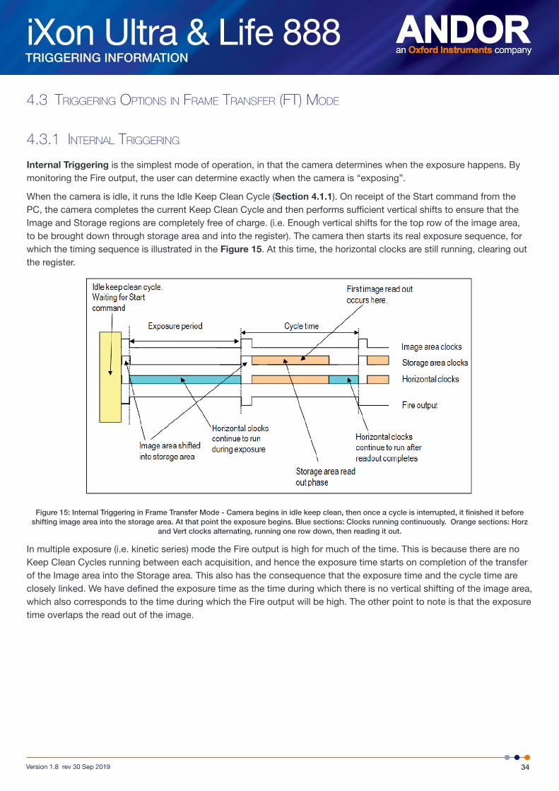
Internal Triggering is the simplest mode of operation, in that the camera determines when the exposure happens. By monitoring the Fire output, the user can determine exactly when the camera is “exposing”.
When the camera is idle, it runs the Idle Keep Clean Cycle (Section 4.1.1). On receipt of the Start command from the PC, the camera completes the current Keep Clean Cycle and then performs sufficient vertical shifts to ensure that the Image and Storage regions are completely free of charge. (i.e. Enough vertical shifts for the top row of the image area, to be brought down through storage area and into the register). The camera then starts its real exposure sequence, for which the timing sequence is illustrated in the Figure 15. At this time, the horizontal clocks are still running, clearing out the register.
Figure 15: Internal Triggering in Frame Transfer Mode - Camera begins in idle keep clean, then once a cycle is interrupted, it finished it before shifting image area into the storage area. At that point the exposure begins. Blue sections: Clocks running continuously. Orange sections: Horz
and Vert clocks alternating, running one row down, then reading it out.
In multiple exposure (i.e. kinetic series) mode the Fire output is high for much of the time. This is because there are no Keep Clean Cycles running between each acquisition, and hence the exposure time starts on completion of the transfer of the Image area into the Storage area. This also has the consequence that the exposure time and the cycle time are closely linked. We have defined the exposure time as the time during which there is no vertical shifting of the image area, which also corresponds to the time during which the Fire output will be high. The other point to note is that the exposure time overlaps the read out of the image.
iXon Ultra & Life 888
35Version 1.8 rev 30 Sep 2019
TRIGGERING INFORMATION
4.3.2 eXteRnal tRiggeRing
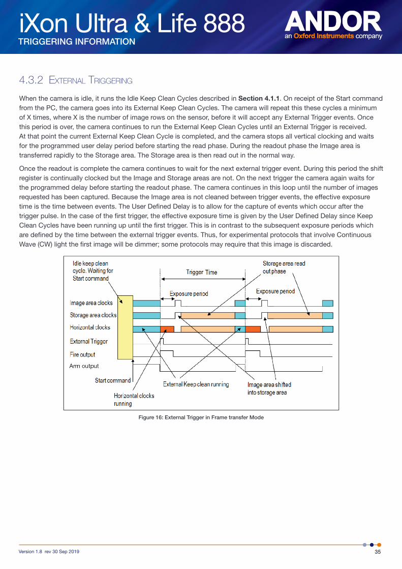
When the camera is idle, it runs the Idle Keep Clean Cycles described in Section 4.1.1. On receipt of the Start command from the PC, the camera goes into its External Keep Clean Cycles. The camera will repeat this these cycles a minimum of X times, where X is the number of image rows on the sensor, before it will accept any External Trigger events. Once this period is over, the camera continues to run the External Keep Clean Cycles until an External Trigger is received. At that point the current External Keep Clean Cycle is completed, and the camera stops all vertical clocking and waits for the programmed user delay period before starting the read phase. During the readout phase the Image area is transferred rapidly to the Storage area. The Storage area is then read out in the normal way.
Once the readout is complete the camera continues to wait for the next external trigger event. During this period the shift register is continually clocked but the Image and Storage areas are not. On the next trigger the camera again waits for the programmed delay before starting the readout phase. The camera continues in this loop until the number of images requested has been captured. Because the Image area is not cleaned between trigger events, the effective exposure time is the time between events. The User Defined Delay is to allow for the capture of events which occur after the trigger pulse. In the case of the first trigger, the effective exposure time is given by the User Defined Delay since Keep Clean Cycles have been running up until the first trigger. This is in contrast to the subsequent exposure periods which are defined by the time between the external trigger events. Thus, for experimental protocols that involve Continuous Wave (CW) light the first image will be dimmer; some protocols may require that this image is discarded.
Figure 16: External Trigger in Frame transfer Mode
iXon Ultra & Life 888
36Version 1.8 rev 30 Sep 2019
TRIGGERING INFORMATION
iCam
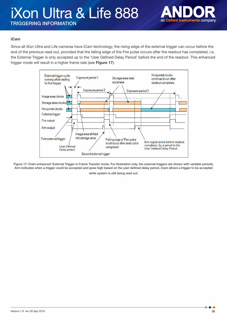
Since all iXon Ultra and Life cameras have iCam technology, the rising edge of the external trigger can occur before the end of the previous read out, provided that the falling edge of the Fire pulse occurs after the readout has completed, i.e. the External Trigger is only accepted up to the ‘User Defined Delay Period’ before the end of the readout. This enhanced trigger mode will result in a higher frame rate (see Figure 17).
Figure 17: iCam-enhanced’ External Trigger in Frame Transfer mode. For illustration only, the external triggers are shown with variable periods.Arm indicates when a trigger could be accepted and goes high based on the user defined delay period. iCam allows a trigger to be accepted
while system is still being read out.
iXon Ultra & Life 888
37Version 1.8 rev 30 Sep 2019
TRIGGERING INFORMATION
4.4 tRiggeRing options in non-fRame tRansfeR (nft) mode
4.4.1 inteRnal tRiggeRing (nft)
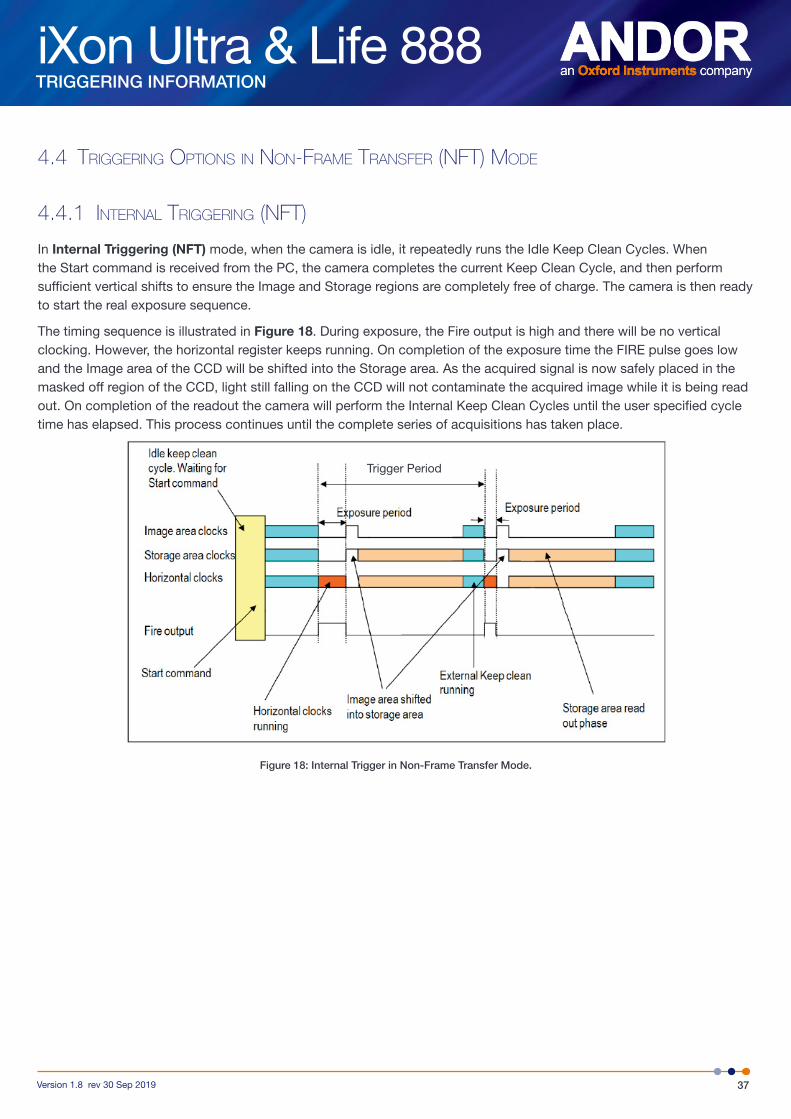
In Internal Triggering (NFT) mode, when the camera is idle, it repeatedly runs the Idle Keep Clean Cycles. When the Start command is received from the PC, the camera completes the current Keep Clean Cycle, and then perform sufficient vertical shifts to ensure the Image and Storage regions are completely free of charge. The camera is then ready to start the real exposure sequence.
The timing sequence is illustrated in Figure 18. During exposure, the Fire output is high and there will be no vertical clocking. However, the horizontal register keeps running. On completion of the exposure time the FIRE pulse goes low and the Image area of the CCD will be shifted into the Storage area. As the acquired signal is now safely placed in the masked off region of the CCD, light still falling on the CCD will not contaminate the acquired image while it is being read out. On completion of the readout the camera will perform the Internal Keep Clean Cycles until the user specified cycle time has elapsed. This process continues until the complete series of acquisitions has taken place.
Figure 18: Internal Trigger in Non-Frame Transfer Mode.
Trigger Period
iXon Ultra & Life 888
38Version 1.8 rev 30 Sep 2019
TRIGGERING INFORMATION
4.4.2 eXteRnal & fast eXteRnal (nft) tRiggeRing
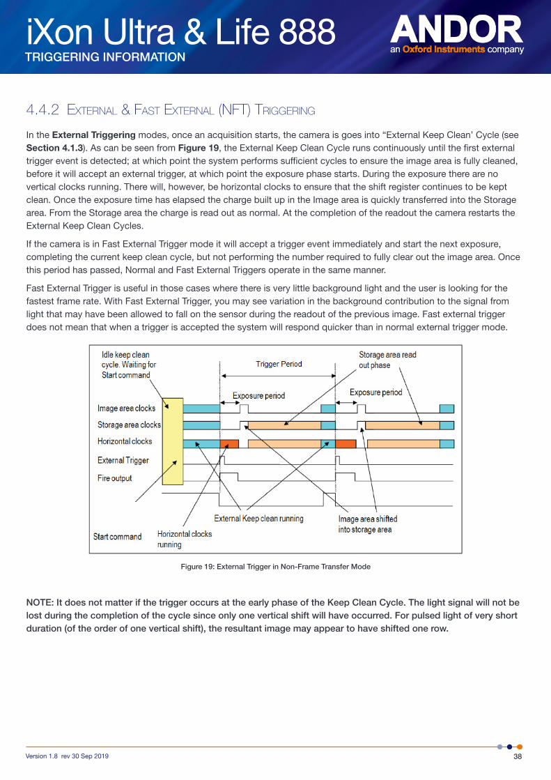
In the External Triggering modes, once an acquisition starts, the camera is goes into “External Keep Clean’ Cycle (see Section 4.1.3). As can be seen from Figure 19, the External Keep Clean Cycle runs continuously until the first external trigger event is detected; at which point the system performs sufficient cycles to ensure the image area is fully cleaned, before it will accept an external trigger, at which point the exposure phase starts. During the exposure there are no vertical clocks running. There will, however, be horizontal clocks to ensure that the shift register continues to be kept clean. Once the exposure time has elapsed the charge built up in the Image area is quickly transferred into the Storage area. From the Storage area the charge is read out as normal. At the completion of the readout the camera restarts the External Keep Clean Cycles.
If the camera is in Fast External Trigger mode it will accept a trigger event immediately and start the next exposure, completing the current keep clean cycle, but not performing the number required to fully clear out the image area. Once this period has passed, Normal and Fast External Triggers operate in the same manner.
Fast External Trigger is useful in those cases where there is very little background light and the user is looking for the fastest frame rate. With Fast External Trigger, you may see variation in the background contribution to the signal from light that may have been allowed to fall on the sensor during the readout of the previous image. Fast external trigger does not mean that when a trigger is accepted the system will respond quicker than in normal external trigger mode.
Figure 19: External Trigger in Non-Frame Transfer Mode
NOTE: It does not matter if the trigger occurs at the early phase of the Keep Clean Cycle. The light signal will not be lost during the completion of the cycle since only one vertical shift will have occurred. For pulsed light of very short duration (of the order of one vertical shift), the resultant image may appear to have shifted one row.
iXon Ultra & Life 888
39Version 1.8 rev 30 Sep 2019
TRIGGERING INFORMATION
4.4.3 eXteRnal eXposuRe (nft) tRiggeRing
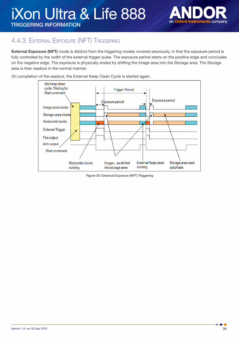
External Exposure (NFT) mode is distinct from the triggering modes covered previously, in that the exposure period is fully controlled by the width of the external trigger pulse. The exposure period starts on the positive edge and concludes on the negative edge. The exposure is physically ended by shifting the Image area into the Storage area. The Storage area is then readout in the normal manner.
On completion of the readout, the External Keep Clean Cycle is started again.
Figure 20: External Exposure (NFT) Triggering
iXon Ultra & Life 888
40Version 1.8 rev 30 Sep 2019
TRIGGERING INFORMATION
4.4.4 softWaRe (nft) tRiggeRing
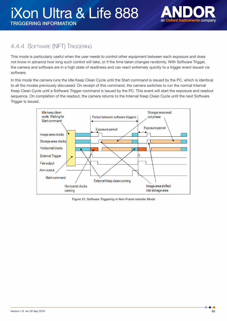
This mode is particularly useful when the user needs to control other equipment between each exposure and does not know in advance how long such control will take, or if the time taken changes randomly. With Software Trigger, the camera and software are in a high state of readiness and can react extremely quickly to a trigger event issued via software.
In this mode the camera runs the Idle Keep Clean Cycle until the Start command is issued by the PC, which is identical to all the modes previously discussed. On receipt of this command, the camera switches to run the normal Internal Keep Clean Cycle until a Software Trigger command is issued by the PC. This event will start the exposure and readout sequence. On completion of the readout, the camera returns to the Internal Keep Clean Cycle until the next Software Trigger is issued.
Figure 21: Software Triggering in Non-Frame transfer Mode
iXon Ultra & Life 888
41Version 1.8 rev 30 Sep 2019
TRIGGERING INFORMATION
4.5 tRiggeRing options in fast kinetics (fk) mode
4.5.1 inteRnal (fk)
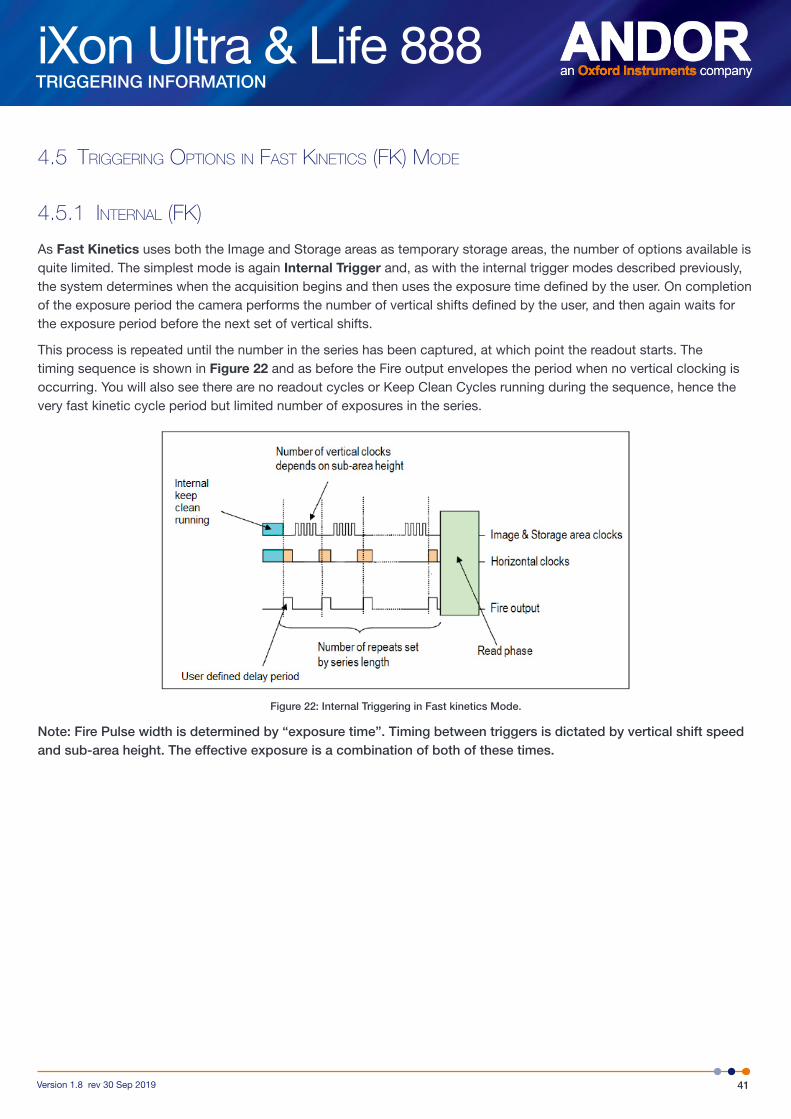
As Fast Kinetics uses both the Image and Storage areas as temporary storage areas, the number of options available is quite limited. The simplest mode is again Internal Trigger and, as with the internal trigger modes described previously, the system determines when the acquisition begins and then uses the exposure time defined by the user. On completion of the exposure period the camera performs the number of vertical shifts defined by the user, and then again waits for the exposure period before the next set of vertical shifts.
This process is repeated until the number in the series has been captured, at which point the readout starts. The timing sequence is shown in Figure 22 and as before the Fire output envelopes the period when no vertical clocking is occurring. You will also see there are no readout cycles or Keep Clean Cycles running during the sequence, hence the very fast kinetic cycle period but limited number of exposures in the series.
Figure 22: Internal Triggering in Fast kinetics Mode.
Note: Fire Pulse width is determined by “exposure time”. Timing between triggers is dictated by vertical shift speed and sub-area height. The effective exposure is a combination of both of these times.
iXon Ultra & Life 888
42Version 1.8 rev 30 Sep 2019
TRIGGERING INFORMATION
4.5.2 eXteRnal (fk)
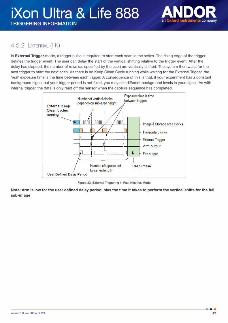
In External Trigger mode, a trigger pulse is required to start each scan in the series. The rising edge of the trigger defines the trigger event. The user can delay the start of the vertical shifting relative to the trigger event. After the delay has elapsed, the number of rows (as specified by the user) are vertically shifted. The system then waits for the next trigger to start the next scan. As there is no Keep Clean Cycle running while waiting for the External Trigger, the ‘real’ exposure time is the time between each trigger. A consequence of this is that, if your experiment has a constant background signal but your trigger period is not fixed, you may see different background levels in your signal. As with internal trigger, the data is only read off the sensor when the capture sequence has completed.
Figure 23: External Triggering in Fast Kinetics Mode
Note: Arm is low for the user defined delay period, plus the time it takes to perform the vertical shifts for the full sub-image

iXon Ultra & Life 888
43Version 1.8 rev 30 Sep 2019
TRIGGERING INFORMATION
4.5.3 eXteRnal staRt (fk)
External Start triggering mode is a combination of External and Internal Trigger. At the start of the capture process, the camera runs the External Keep Clean Cycle, waiting for a trigger pulse to be applied to the External Trigger input. On receiving the trigger the exposure starts. The exposure period is defined by the user. On completion of the exposure period, the camera performs the number of vertical shifts defined by the sub-area height (set by the user) and, then again, waits for the exposure period before the next set of vertical shifts. This process is repeated until the number in the series has been captured at which point the readout starts.
Figure 24: External Start Trigger in Fast Kinetics mode
iXon Ultra & Life 888
44Version 1.8 rev 30 Sep 2019
TRIGGERING INFORMATION
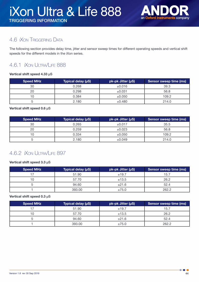
4.6 iXon tRiggeRing data
The following section provides delay time, jitter and sensor sweep times for different operating speeds and vertical shift speeds for the different models in the iXon series.
4.6.1 iXon ultRa/life 888
Vertical shift speed 4.33 µS
Speed MHz Typical delay (µS) pk-pk Jitter (µS) Sensor sweep time (ms)
30 0.268 ±0.016 39.3
20 0.298 ±0.031 56.8
10 0.384 ±0.050 109.2
5 2.180 ±0.480 214.0
Vertical shift speed 0.6 µS
Speed MHz Typical delay (µS) pk-pk Jitter (µS) Sensor sweep time (ms)
30 0.265 ±0.017 35.5
20 0.259 ±0.023 56.8
10 0.334 ±0.050 109.2
5 2.180 ±0.049 214.0
4.6.2 iXon ultRa/life 897
Vertical shift speed 3.3 µS
Speed MHz Typical delay (µS) pk-pk Jitter (µS) Sensor sweep time (ms)
17 51.90 ±19.7 15.7
10 57.70 ±13.5 26.2
5 94.60 ±21.6 52.4
1 393.00 ±75.0 262.2
Vertical shift speed 0.3 µS
Speed MHz Typical delay (µS) pk-pk Jitter (µS) Sensor sweep time (ms)
17 51.90 ±19.7 15.7
10 57.70 ±13.5 26.2
5 94.60 ±21.6 52.4
1 393.00 ±75.0 262.2
iXon Ultra & Life 888
45Version 1.8 rev 30 Sep 2019
TRIGGERING INFORMATION
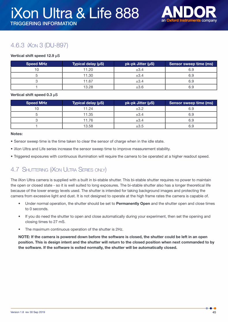
4.6.3 iXon 3 (du-897)
Vertical shift speed 12.9 µS
Speed MHz Typical delay (µS) pk-pk Jitter (µS) Sensor sweep time (ms)
10 11.20 ±3.4 6.9
5 11.30 ±3.4 6.9
3 11.67 ±3.4 6.9
1 13.28 ±3.6 6.9
Vertical shift speed 0.3 µS
Speed MHz Typical delay (µS) pk-pk Jitter (µS) Sensor sweep time (ms)
10 11.24 ±3.2 6.9
5 11.35 ±3.4 6.9
3 11.76 ±3.4 6.9
1 13.58 ±3.5 6.9
Notes:
• Sensor sweep time is the time taken to clear the sensor of charge when in the idle state.
• iXon Ultra and Life series increase the sensor sweep time to improve measurement stability.
• Triggered exposures with continuous illumination will require the camera to be operated at a higher readout speed.
4.7 sHutteRing (iXon ultRa seRies only)
The iXon Ultra camera is supplied with a built in bi-stable shutter. This bi-stable shutter requires no power to maintain the open or closed state - so it is well suited to long exposures. The bi-stable shutter also has a longer theoretical life because of the lower energy levels used. The shutter is intended for taking background images and protecting the camera from excessive light and dust. It is not designed to operate at the high frame rates the camera is capable of.
• Under normal operation, the shutter should be set to Permanently Open and the shutter open and close times to 0 seconds.
• If you do need the shutter to open and close automatically during your experiment, then set the opening and closing times to 27 mS.
• The maximum continuous operation of the shutter is 2Hz.
NOTE: If the camera is powered down before the software is closed, the shutter could be left in an open position. This is design intent and the shutter will return to the closed position when next commanded to by the software. If the software is exited normally, the shutter will be automatically closed.
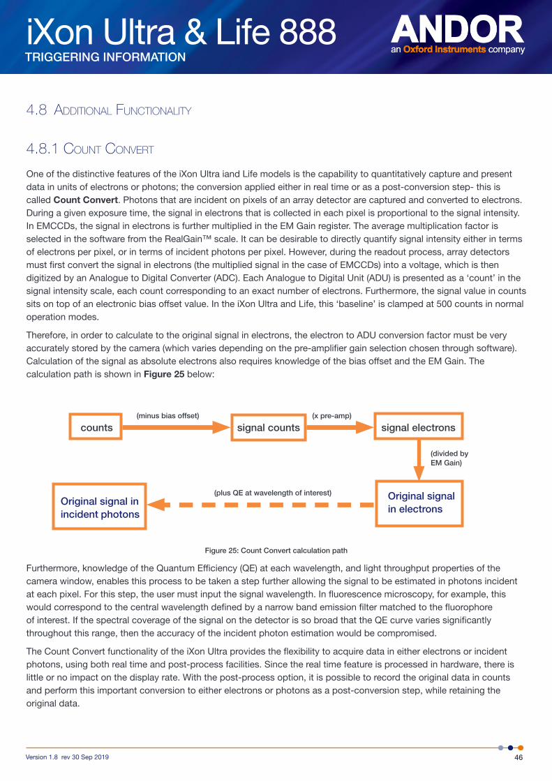
iXon Ultra & Life 888
46Version 1.8 rev 30 Sep 2019
TRIGGERING INFORMATION
4.8 additional functionality
4.8.1 count conveRt
One of the distinctive features of the iXon Ultra iand Life models is the capability to quantitatively capture and present data in units of electrons or photons; the conversion applied either in real time or as a post-conversion step- this is called Count Convert. Photons that are incident on pixels of an array detector are captured and converted to electrons. During a given exposure time, the signal in electrons that is collected in each pixel is proportional to the signal intensity. In EMCCDs, the signal in electrons is further multiplied in the EM Gain register. The average multiplication factor is selected in the software from the RealGain™ scale. It can be desirable to directly quantify signal intensity either in terms of electrons per pixel, or in terms of incident photons per pixel. However, during the readout process, array detectors must first convert the signal in electrons (the multiplied signal in the case of EMCCDs) into a voltage, which is then digitized by an Analogue to Digital Converter (ADC). Each Analogue to Digital Unit (ADU) is presented as a ‘count’ in the signal intensity scale, each count corresponding to an exact number of electrons. Furthermore, the signal value in counts sits on top of an electronic bias offset value. In the iXon Ultra and Life, this ‘baseline’ is clamped at 500 counts in normal operation modes.
Therefore, in order to calculate to the original signal in electrons, the electron to ADU conversion factor must be very accurately stored by the camera (which varies depending on the pre-amplifier gain selection chosen through software). Calculation of the signal as absolute electrons also requires knowledge of the bias offset and the EM Gain. The calculation path is shown in Figure 25 below:
Figure 25: Count Convert calculation path
Furthermore, knowledge of the Quantum Efficiency (QE) at each wavelength, and light throughput properties of the camera window, enables this process to be taken a step further allowing the signal to be estimated in photons incident at each pixel. For this step, the user must input the signal wavelength. In fluorescence microscopy, for example, this would correspond to the central wavelength defined by a narrow band emission filter matched to the fluorophore of interest. If the spectral coverage of the signal on the detector is so broad that the QE curve varies significantly throughout this range, then the accuracy of the incident photon estimation would be compromised.
The Count Convert functionality of the iXon Ultra provides the flexibility to acquire data in either electrons or incident photons, using both real time and post-process facilities. Since the real time feature is processed in hardware, there is little or no impact on the display rate. With the post-process option, it is possible to record the original data in counts and perform this important conversion to either electrons or photons as a post-conversion step, while retaining the original data.
counts signal counts signal electrons
Original signal in electrons
Original signal in incident photons
(minus bias offset) (x pre-amp)
(divided by EM Gain)
(plus QE at wavelength of interest)

iXon Ultra & Life 888
47Version 1.8 rev 30 Sep 2019
TRIGGERING INFORMATION
4.9 optacquiRe
OptAcquire is a unique control interface, whereby a user can conveniently choose from a predetermined list of set-up configurations, each designed to optimize the camera for different experimental acquisition types, thus removing complexity from the extremely adaptable control architecture of the iXon Ultra and Life models. The control architecture is extremely tuneable, meaning the camera can be adapted and optimized for a wide variety of quantitative experimental requirements, ranging from fast single photon counting through to slower scan, 16-bit dynamic range measurements. However, successfully optimizing EMCCD technology is not a trivial exercise, with various set-up parameters directly influencing different camera performance characteristics. OptAcquire has been designed as a unique interface whereby a user can choose from a predetermined list of eleven camera set-up configurations. A variety of set-up parameters are balanced behind the scenes through the OptAquire menu. Furthermore, advanced users may wish to create their own additional OptAcquire configuation. Control parameters include:
• EM Gain – This parameter has a direct bearing on both sensitivity and dynamic range.
• Vertical clock speed – Flexibility in this parameter is critical to optimizing the camera for lowest noise, fastest speed, minimal frame transfer smear or maximum pixel well depth.
• Vertical Clock Amplitude – Can be used to compensate charge transfer when the sensor is being ‘over-clocked’ and also to reduce charge leakage into the image area when there is saturated signal in the frame transfer storage area (e.g. when combining very short exposure with a slow readout speed).
• Horizontal readout speed – Range: iXon Ultra - 30Mhz and 0.1Mhz; iXon Life - 30Mhz and 10Mhz
• Pre-amplifier gain – Trading off reduced digitization noise versus accessing full pixel well depth.
• EM / Conventional amplifier – EMCCD operation provides ultimate sensitivity. The iXon Ultra can also run in a traditional high dynamic range CCD mode. This conventional mode is recommended for relatively ‘brighter’ signals, or when it is possible to apply long exposures to overcome read noise floor.
• Frame Transfer (overlap) – Overlapped readout is used to achieve 100% duty cycle, ideal for fastest frame rate measurements without switching exposure time between frames. This mode should be deselected for time-lapse experiments.
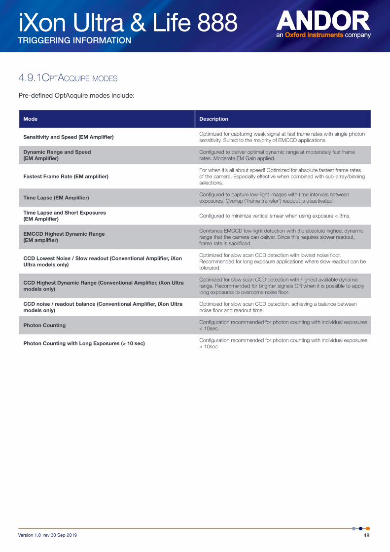
iXon Ultra & Life 888
48Version 1.8 rev 30 Sep 2019
TRIGGERING INFORMATION
4.9.1optacquiRe modes
Pre-defined OptAcquire modes include:
Mode Description
Sensitivity and Speed (EM Amplifier)Optimized for capturing weak signal at fast frame rates with single photon sensitivity. Suited to the majority of EMCCD applications.
Dynamic Range and Speed (EM Amplifier)
Configured to deliver optimal dynamic range at moderately fast frame rates. Moderate EM Gain applied.
Fastest Frame Rate (EM amplifier)For when it’s all about speed! Optimized for absolute fastest frame rates of the camera. Especially effective when combined with sub-array/binning selections.
Time Lapse (EM Amplifier)Configured to capture low-light images with time intervals between exposures. Overlap (‘frame transfer’) readout is deactivated.
Time Lapse and Short Exposures (EM Amplifier)
Configured to minimize vertical smear when using exposure < 3ms.
EMCCD Highest Dynamic Range (EM amplifier)
Combines EMCCD low-light detection with the absolute highest dynamic range that the camera can deliver. Since this requires slower readout, frame rate is sacrificed.
CCD Lowest Noise / Slow readout (Conventional Amplifier, iXon Ultra models only)
Optimized for slow scan CCD detection with lowest noise floor. Recommended for long exposure applications where slow readout can be tolerated.
CCD Highest Dynamic Range (Conventional Amplifier, iXon Ultra models only)
Optimized for slow scan CCD detection with highest available dynamic range. Recommended for brighter signals OR when it is possible to apply long exposures to overcome noise floor.
CCD noise / readout balance (Conventional Amplifier, iXon Ultra models only)
Optimized for slow scan CCD detection, achieving a balance between noise floor and readout time.
Photon CountingConfiguration recommended for photon counting with individual exposures < 10sec.
Photon Counting with Long Exposures (> 10 sec)Configuration recommended for photon counting with individual exposures > 10sec.
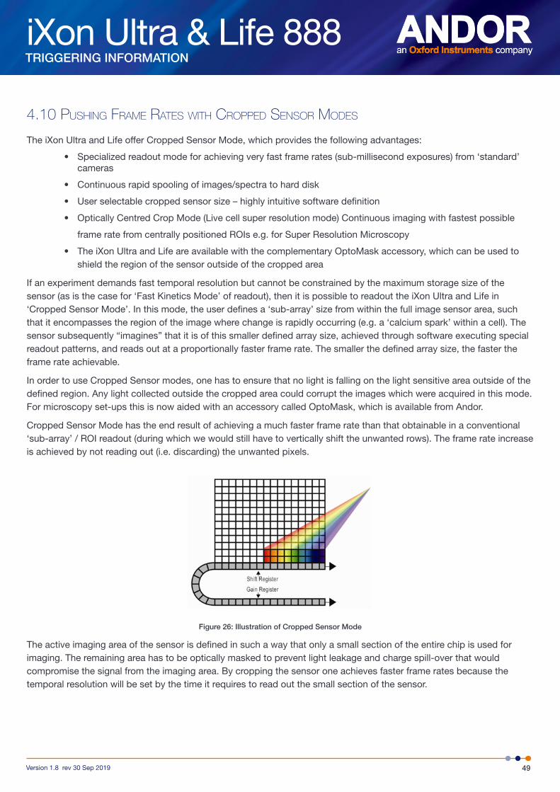
iXon Ultra & Life 888
49Version 1.8 rev 30 Sep 2019
TRIGGERING INFORMATION
4.10 pusHing fRame Rates WitH cRopped sensoR modes
The iXon Ultra and Life offer Cropped Sensor Mode, which provides the following advantages:
• Specialized readout mode for achieving very fast frame rates (sub-millisecond exposures) from ‘standard’ cameras
• Continuous rapid spooling of images/spectra to hard disk
• User selectable cropped sensor size – highly intuitive software definition
• Optically Centred Crop Mode (Live cell super resolution mode) Continuous imaging with fastest possible
frame rate from centrally positioned ROIs e.g. for Super Resolution Microscopy
• The iXon Ultra and Life are available with the complementary OptoMask accessory, which can be used to shield the region of the sensor outside of the cropped area
If an experiment demands fast temporal resolution but cannot be constrained by the maximum storage size of the sensor (as is the case for ‘Fast Kinetics Mode’ of readout), then it is possible to readout the iXon Ultra and Life in ‘Cropped Sensor Mode’. In this mode, the user defines a ‘sub-array’ size from within the full image sensor area, such that it encompasses the region of the image where change is rapidly occurring (e.g. a ‘calcium spark’ within a cell). The sensor subsequently “imagines” that it is of this smaller defined array size, achieved through software executing special readout patterns, and reads out at a proportionally faster frame rate. The smaller the defined array size, the faster the frame rate achievable.
In order to use Cropped Sensor modes, one has to ensure that no light is falling on the light sensitive area outside of the defined region. Any light collected outside the cropped area could corrupt the images which were acquired in this mode. For microscopy set-ups this is now aided with an accessory called OptoMask, which is available from Andor.
Cropped Sensor Mode has the end result of achieving a much faster frame rate than that obtainable in a conventional ‘sub-array’ / ROI readout (during which we would still have to vertically shift the unwanted rows). The frame rate increase is achieved by not reading out (i.e. discarding) the unwanted pixels.
Figure 26: Illustration of Cropped Sensor Mode
The active imaging area of the sensor is defined in such a way that only a small section of the entire chip is used for imaging. The remaining area has to be optically masked to prevent light leakage and charge spill-over that would compromise the signal from the imaging area. By cropping the sensor one achieves faster frame rates because the temporal resolution will be set by the time it requires to read out the small section of the sensor.
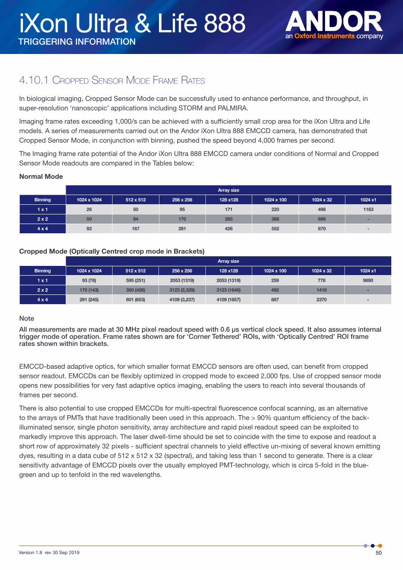
iXon Ultra & Life 888
50Version 1.8 rev 30 Sep 2019
TRIGGERING INFORMATION
4.10.1 cRopped sensoR mode fRame Rates
In biological imaging, Cropped Sensor Mode can be successfully used to enhance performance, and throughput, in super-resolution ‘nanoscopic’ applications including STORM and PALMIRA.
Imaging frame rates exceeding 1,000/s can be achieved with a sufficiently small crop area for the iXon Ultra and Life models. A series of measurements carried out on the Andor iXon Ultra 888 EMCCD camera, has demonstrated that Cropped Sensor Mode, in conjunction with binning, pushed the speed beyond 4,000 frames per second.
The Imaging frame rate potential of the Andor iXon Ultra 888 EMCCD camera under conditions of Normal and Cropped Sensor Mode readouts are compared in the Tables below:
Normal Mode
Array size
Binning 1024 x 1024 512 x 512 256 x 256 128 x128 1024 x 100 1024 x 32 1024 x1
1 x 1 26 50 95 171 220 498 1163
2 x 2 50 94 170 285 368 699 -
4 x 4 92 167 281 426 552 870 -
Cropped Mode (Optically Centred crop mode in Brackets)Array size
Binning 1024 x 1024 512 x 512 256 x 256 128 x128 1024 x 100 1024 x 32 1024 x1
1 x 1 93 (78) 595 (251) 2053 (1319) 2053 (1319) 259 778 9690
2 x 2 170 (143) 350 (426) 3123 (2,329) 3123 (1646) 492 1416 -
4 x 4 291 (245) 601 (653) 4109 (3,237) 4109 (1857) 887 2370 -
Note
All measurements are made at 30 MHz pixel readout speed with 0.6 µs vertical clock speed. It also assumes internal trigger mode of operation. Frame rates shown are for ‘Corner Tethered’ ROIs, with ‘Optically Centred’ ROI frame rates shown within brackets.
EMCCD-based adaptive optics, for which smaller format EMCCD sensors are often used, can benefit from cropped sensor readout. EMCCDs can be flexibly optimized in cropped mode to exceed 2,000 fps. Use of cropped sensor mode opens new possibilities for very fast adaptive optics imaging, enabling the users to reach into several thousands of frames per second.
There is also potential to use cropped EMCCDs for multi-spectral fluorescence confocal scanning, as an alternative to the arrays of PMTs that have traditionally been used in this approach. The > 90% quantum efficiency of the back-illuminated sensor, single photon sensitivity, array architecture and rapid pixel readout speed can be exploited to markedly improve this approach. The laser dwell-time should be set to coincide with the time to expose and readout a short row of approximately 32 pixels - sufficient spectral channels to yield effective un-mixing of several known emitting dyes, resulting in a data cube of 512 x 512 x 32 (spectral), and taking less than 1 second to generate. There is a clear sensitivity advantage of EMCCD pixels over the usually employed PMT-technology, which is circa 5-fold in the blue-green and up to tenfold in the red wavelengths.

iXon Ultra & Life 888
51Version 1.8 rev 30 Sep 2019
TRIGGERING INFORMATION
4.11 advanced pHoton counting in emccds (iXon ultRa models only)
Photon Counting in EMCCDs is a way to overcome the multiplicative noise associated with the amplification process, thereby increasing the signal to noise ratio by a factor of root 2 (and doubling the effective quantum efficiency of the EMCCD). Only EMCCDs with low noise floor can perform photon counting. The approach can be further enhanced through innovative ways to post process kinetic data. The industry-leading dark current and Clock Induced Charge (CIC) specification of the Andor’s back-illuminated iXon Ultra 888 model renders it uniquely suited to imaging by Photon Counting.
Photon Counting can only be successfully carried out with very weak signals because, as the name suggests, it involves counting only single photons per pixel. If more than one photon falls on a pixel during the exposure, an EMCCD (or an ICCD for that matter) cannot distinguish the resulting signal spike from that of a single photon event, and thus the dynamic range of a single frame exposure is restricted to one photon.
Key Fact – To successfully photon count with EMCCDs, there has to be a significantly higher probability of seeing a ‘photon spike’ than seeing a dark current / CIC ‘noise spike’. The iXon Ultra and Life series have the lowest dark current / CIC performance on the market, yielding both lower detection limits and higher contrast images.
Under such ultra low-light conditions, ‘photon counting mode’ imaging carries the key benefit that it is a means to circumvent the Multiplicative Noise (also known as ‘Noise Factor’). Multiplicative Noise is a by-product of the Electron Multiplication process and affects both EMCCDs and ICCDs. In fact, it has been measured to be significantly higher in ICCDs. The noise factor of EMCCDs is well theorized and measured; to account for it you increase the shot noise of the signal by a factor of square root 2 (~x1.41). This gives the new ‘effective shot noise’ that has been corrected for multiplicative noise. The effect of this additional noise source on the overall Signal to Noise ratio can be readily viewed in the S/N plots in the technical note entitled ‘EMCCD signal to noise plots’.
Photon Counting Mode does not measure the exact intensity of a single photon spike, it merely registers its presence above a threshold value. It does this for a succession of exposures and combines the individual ‘binary’ images to create the final image. As such, this mode of operation is not affected by the multiplication noise (which otherwise describes the distribution of multiplication values around the mean multiplication factor chosen). The end result is that low-light images, acquired through this mode of acquisition, are improved by a factor of ~x1.41 Signal to Noise, compared to a single integrated image with the same overall exposure time.
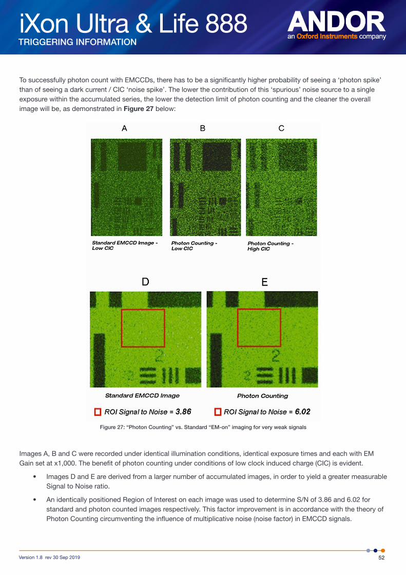
iXon Ultra & Life 888
52Version 1.8 rev 30 Sep 2019
TRIGGERING INFORMATION
To successfully photon count with EMCCDs, there has to be a significantly higher probability of seeing a ‘photon spike’ than of seeing a dark current / CIC ‘noise spike’. The lower the contribution of this ‘spurious’ noise source to a single exposure within the accumulated series, the lower the detection limit of photon counting and the cleaner the overall image will be, as demonstrated in Figure 27 below:
Figure 27: “Photon Counting” vs. Standard “EM-on” imaging for very weak signals
Images A, B and C were recorded under identical illumination conditions, identical exposure times and each with EM Gain set at x1,000. The benefit of photon counting under conditions of low clock induced charge (CIC) is evident.
• Images D and E are derived from a larger number of accumulated images, in order to yield a greater measurable Signal to Noise ratio.
• An identically positioned Region of Interest on each image was used to determine S/N of 3.86 and 6.02 for standard and photon counted images respectively. This factor improvement is in accordance with the theory of Photon Counting circumventing the influence of multiplicative noise (noise factor) in EMCCD signals.

iXon Ultra & Life 888
53Version 1.8 rev 30 Sep 2019
TRIGGERING INFORMATION
4.11.1 pHoton counting by post-pRocessing
As a post-processing analysis, the user is able to ‘trial and error’ photon counting for a pre-recorded kinetic series, trading-off temporal resolution vs SNR by choosing how many images should contribute to each photon counted accumulated image.
For example, a series of 1,000 images could be broken down into groups of 20 photon counted images, yielding 50 time points. If it transpires that better SNR is required, the original dataset could be re-treated using groups of 50 photon counted images, yielding 20 time points.
Figure 28: Schematic illustration of how photon counting can be applied to a kinetic series as a post processing step, affording increased flexibility in ‘trial and error’ trading temporal resolution vs SNR.
1. Lower SNR, Higher temporal resolution
2. Higher SNR, Lower temporal resolution
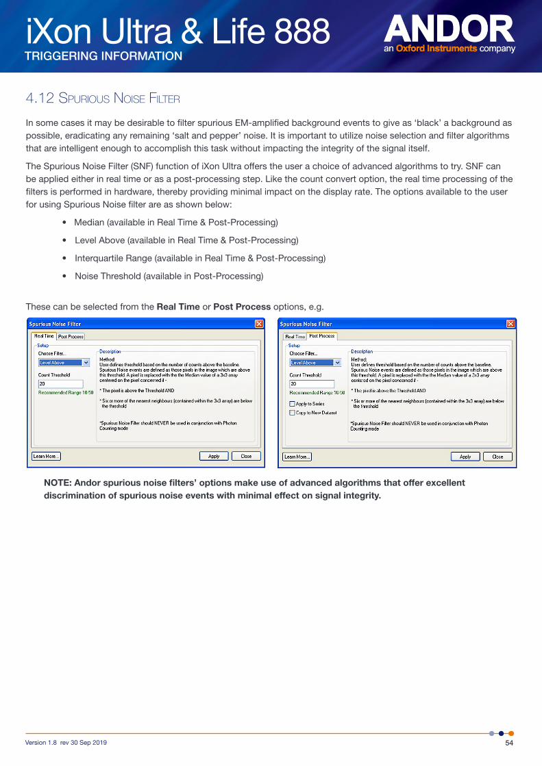
iXon Ultra & Life 888
54Version 1.8 rev 30 Sep 2019
TRIGGERING INFORMATION
4.12 spuRious noise filteR
In some cases it may be desirable to filter spurious EM-amplified background events to give as ‘black’ a background as possible, eradicating any remaining ‘salt and pepper’ noise. It is important to utilize noise selection and filter algorithms that are intelligent enough to accomplish this task without impacting the integrity of the signal itself.
The Spurious Noise Filter (SNF) function of iXon Ultra offers the user a choice of advanced algorithms to try. SNF can be applied either in real time or as a post-processing step. Like the count convert option, the real time processing of the filters is performed in hardware, thereby providing minimal impact on the display rate. The options available to the user for using Spurious Noise filter are as shown below:
• Median (available in Real Time & Post-Processing)
• Level Above (available in Real Time & Post-Processing)
• Interquartile Range (available in Real Time & Post-Processing)
• Noise Threshold (available in Post-Processing)
These can be selected from the Real Time or Post Process options, e.g.
NOTE: Andor spurious noise filters’ options make use of advanced algorithms that offer excellent discrimination of spurious noise events with minimal effect on signal integrity.

iXon Ultra & Life 888
55Version 1.8 rev 30 Sep 2019
TROUBLESHOOTING
SECTION 5: TROUBLESHOOTING
5.1 unit does not sWitcH on
• Check power cord is plugged in and connected correctly to mains supply
• If applicable, replace fuse in the supplied mains cable as detailed in Section 6.2.4
• If the unit still does not switch on after the checks above have been carried out, contact Andor Technical Support
5.2 suppoRt device not Recognised WHen plugged into pc
• Choose another USB port
• Check connections
5.3 tempeRatuRe tRip alaRm sounds (continuous tone)
To protect the camera from overheating, a thermal switch has been attached to the heat sink. If the temperature of the heat sink rises above the predefined limit, the power supply to the cooler will cut off and a buzzer will sound. Should the buzzer sound ensure the following:
Air Cooling
• Check that the air vents on the sides of the detector head are not blocked
• There is sufficient clearance (100 mm) around the camera
• The ambient air temperature is not above 30ºC
• The fan has not been deactivated (or the speed set too low) in software
• Check that no foreign bodies are obstructing the fan’s rotation
Water Cooling
• That there is sufficient water flow passing through the camera head
NOTE: When using water cooling, always use water that is above the dew point of the ambient environment to prevent condensation from occurring.
The thermal cut-out will not reset until the camera has been powered off and the temperature of the metalwork reaches a predefined limit. Operation of the camera under conditions that cause repeated cut-outs is not recommended, as thermal cycling will unnecessarily cycle the components and solder joints in the system.
iXon Ultra & Life 888
56Version 1.8 rev 30 Sep 2019
TROUBLESHOOTING
5.4 cameRa HigH fifo fill alaRm
The iXon Ultra and Life 888 support USB 3.0. The camera will function in a USB 2.0 port – but will not sustain the full camera frame rate. Camera High FIFO fill alarms will likely occur if the Ultra 888 is used with a USB 2.0 PC port.
In addition, it has been observed in some systems that a camera may stop acquiring after approximately 1 - 10 seconds. When this occurs it has been found to be due to insufficient USB bandwidth. The camera includes a buffer (FIFO) to overcome any short term bandwidth reductions, however, sustained insufficient bandwidth will always cause the buffer to overflow – regardless of what size of buffer is used. The PC should be able to cope with a sustained USB data transfer of equal to or greater than 60 Megabytes/second. Modern machines should all be able to cope with this.
5.5 usb 3.0 inteR-opeRability
USB 3.0 is a relatively new interface type, so it is possible that Inter-operability problems may occur.
Inter-operability problems could manifest as;
• Failure to detect connection of the iXon Ultra to the USB 3.0 port
• Failure to recognise the iXon Ultra in the device manager
• Intermittent loss of communication with the camera.
• Intermittent Camera FiFO fill alarms
If these occur, then check the firmware and driver status of the USB 3.0 interface on the PC or install the USB 3.0 card supplied with the camera.
iXon Ultra & Life 888
57Version 1.8 rev 30 Sep 2019
MAINTENANCE
SECTION 6: MAINTENANCE
6.1 cleaning cameRa eXteRioR
Only use a dry, clean, lint free cloth to clean the painted surfaces. If necessary, use a water diluted mild detergent to lightly dampen the cloth- do not use Isopropyl alcohol, solvents or aerosols.
6.2 RegulaR cHecks
The state of the product should be checked regularly, especially the following:
• The integrity of the enclosure
• Any water hoses used
• The AC/DC External Power Supply
• The mains cable
WARNING: Do not use equipment that is damaged.
6.2.1 annual electRical safety cHecks
It is advisable to check the integrity of the insulation and protective earth of the product on an annual basis, e.g. U.K. PAT testing of the PS-90 Power supply.
6.3 Replacement paRts
The supplied PS-90 PSU is the only recommended external power supply for use with the iXon camera. If this unit is faulty or damaged, please contact Andor for a replacement. Depending on the Terms and Conditions of your Warranty, you may be charged for this replacement. There are no user replaceable parts in the camera head- please contact your nearest Andor representative (see Section 1.1) if required.
6.4 fuse Replacement
The camera itself does not have a fuse. However, if a U.K. (BS 1363) mains lead has been supplied, it contains a fuse, whose characteristics are as follow:
• Rated Current: 5 A
• Rated Voltage: 240 Vac
• Type: BS 1362
• Size: 6.3 × 25.4 mm (¼ × 1 inches) cartridge
For continued protection, always replace with a fuse of the same type and rating.
WARNING: Do not use equipment that is damaged.
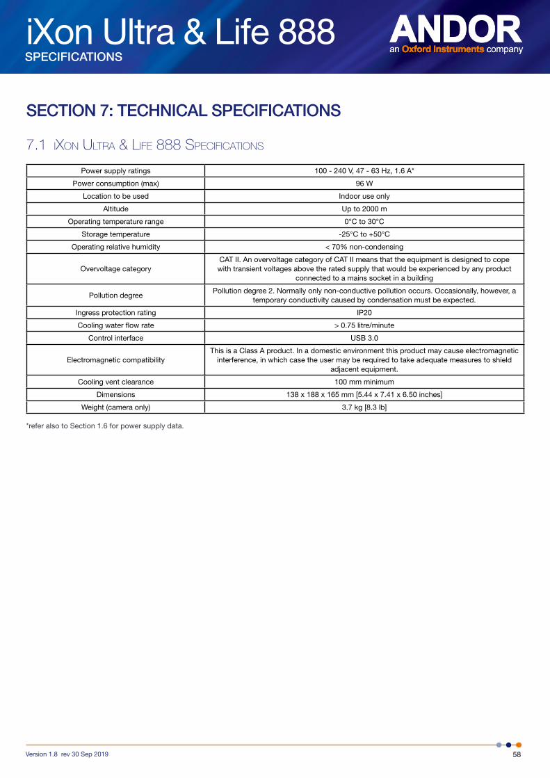
iXon Ultra & Life 888
58Version 1.8 rev 30 Sep 2019
SPECIFICATIONS
SECTION 7: TECHNICAL SPECIFICATIONS
7.1 iXon ultRa & life 888 specifications
Power supply ratings 100 - 240 V, 47 - 63 Hz, 1.6 A*
Power consumption (max) 96 W
Location to be used Indoor use only
Altitude Up to 2000 m
Operating temperature range 0°C to 30°C
Storage temperature -25°C to +50°C
Operating relative humidity < 70% non-condensing
Overvoltage categoryCAT II. An overvoltage category of CAT II means that the equipment is designed to cope with transient voltages above the rated supply that would be experienced by any product
connected to a mains socket in a building
Pollution degreePollution degree 2. Normally only non-conductive pollution occurs. Occasionally, however, a
temporary conductivity caused by condensation must be expected.
Ingress protection rating IP20
Cooling water flow rate > 0.75 litre/minute
Control interface USB 3.0
Electromagnetic compatibilityThis is a Class A product. In a domestic environment this product may cause electromagnetic
interference, in which case the user may be required to take adequate measures to shield adjacent equipment.
Cooling vent clearance 100 mm minimum
Dimensions 138 x 188 x 165 mm [5.44 x 7.41 x 6.50 inches]
Weight (camera only) 3.7 kg [8.3 lb]
*refer also to Section 1.6 for power supply data.

iXon Ultra & Life 888
59Version 1.8 rev 30 Sep 2019
MECHANICAL DRAWINGS
APPENDIX A: MECHANICAL DRAWINGS
Note: iXon Ultra 888 shown. iXon Life model does not have a CameraLink connector
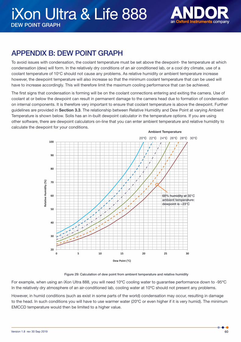
iXon Ultra & Life 888
60Version 1.8 rev 30 Sep 2019
DEW POINT GRAPH
APPENDIX B: DEW POINT GRAPHTo avoid issues with condensation, the coolant temperature must be set above the dewpoint- the temperature at which condensation (dew) will form. In the relatively dry conditions of an air conditioned lab, or a cool dry climate, use of a coolant temperature of 10°C should not cause any problems. As relative humidity or ambient temperature increase however, the dewpoint temperature will also increase so that the minimum coolant temperature that can be used will have to increase accordingly. This will therefore limit the maximum cooling performance that can be achieved.
The first signs that condensation is forming will be on the coolant connections entering and exiting the camera. Use of coolant at or below the dewpoint can result in permanent damage to the camera head due to formation of condensation on internal components. It is therefore very important to ensure that coolant temperature is above the dewpoint. Further guidelines are provided in Section 3.3. The relationship between Relative Humidity and Dew Point at varying Ambient Temperature is shown below. Solis has an in-built dewpoint calculator in the temperature options. If you are using other software, there are dewpoint calculators on-line that you can enter ambient temperature and relative humidity to calculate the dewpoint for your conditions.
20
30
40
50
60
70
80
90
100
0 5 10 15 20 25 30
Rela
tive
Hum
idity
(%)
Dew Point (°C)
Figure 29: Calculation of dew point from ambient temperature and relative humidity
For example, when using an iXon Ultra 888, you will need 10ºC cooling water to guarantee performance down to -95ºC In the relatively dry atmosphere of an air-conditioned lab, cooling water at 10ºC should not present any problems.
However, in humid conditions (such as exist in some parts of the world) condensation may occur, resulting in damage to the head. In such conditions you will have to use warmer water (20ºC or even higher if it is very humid). The minimum EMCCD temperature would then be limited to a higher value.
68% humidity at 30°C ambient temperature: dewpoint is ~23°C
Ambient Temperature
20°C 22°C 24°C 26°C 28°C 30°C

iXon Ultra & Life 888
61Version 1.8 rev 30 Sep 2019
EMCCD TECHNOLOGY
APPENDIX C: EMCCD TECHNOLOGY
WHat is an eleCtron multiplying CCd?Electron Multiplying Charge Coupled Device (EMCCD) is a type of image sensor that is capable of detecting single photon events without an image intensifier (achievable by way of a unique electron multiplying structure built into the chip). Extremely weak signals may be detected above the read noise of the camera at any readout speed. This is important, because the traditional problem of combining sensitivity with speed in standard CCDs is that the two are mutually exclusive, i.e. greater read noise detection limits result from faster pixel readout.
does emCCd teCHnology eliminate read out noise?System noise within modern silicon based detectors has two primary sources: dark current noise and read noise. The higher the noise floor on a detector the less able it is to read out the extremely weak signals associated with ultra low-light imaging.
With thermoelectric cooling, dark current noise can be reduced to negligible levels. An EMCCD’s ability to multiply weak signals above the detector’s read noise floor, by applying EM Gain, effectively eliminates read noise at any speed by reducing it to < 1 e-/p/s.
HoW sensitiVe are emCCds?Two parameters significantly influence detector sensitivity, namely Quantum Efficiency (QE) and system noise. QE is a measure of a camera’s ability to capture valuable photons. A high QE results in more photons being converted to photoelectrons within the EMCCD pixels.
Once converted, the photoelectrons in a given pixel must overcome the detection limit or noise floor of the camera, which is set by the system noise. EMCCDs deliver superior sensitivity by maximizing QE and minimizing system noise, through the unique gain control feature. Single photon events are now well within the capabilities of super sensitive EMCCD technology.
WHat appliCations are emCCds suitable for?EMCCD based detectors have been designed for the most demanding of low-light, dynamic applications. The detection limit is as low as single photons.
These levels of sensitivity are vital for low-light, life science and physical science imaging applications such as single molecule detection, live cell microscopy, weak luminescence detection, or demanding astronomy applications (to name only a few).
WHat is andor teCHnology’s experienCe WitH emCCds?Andor Technology was the first company to introduce an EMCCD based detector in 2000. Since then the company has led the way in the development of EMCCD detectors, introducing the first back illuminated EMCCD in January 2003. Andor now offers the widest range of EMCCD based detectors on the market. Please go to www.emccd.com for further details.

iXon Ultra & Life 888
62Version 1.8 rev 30 Sep 2019
EMCCD TECHNOLOGY
emCCd sensorAll EMCCD sensors in the iXon Ultra and Life ranges have a frame transfer architecture. The frame-transfer EMCCD uses a two-part sensor in which one-half of the array is used as a storage region and is protected from light by a light-tight mask. Incoming photons are allowed to fall on the uncovered portion of the array and the accumulated charge is then rapidly shifted into the masked storage region for transfer to the serial output register. While the signal is being integrated on the light-sensitive portion of the sensor, the stored charge is read out. Frame transfer devices have typically faster frame rates than full frame devices, and have the advantage of a high duty cycle i.e. the sensor is always collecting light.
A potential disadvantage of this architecture is the charge smearing during the transfer from the light-sensitive to the masked regions of the EMCCD (although they are significantly better than full frame devices).The smearing is more prevalent when exposure times are closer to the time taken to shift the charge under the mask (in the order of milliseconds). With the iXon EMCCD series, vertical clock speeds can be tuned via the software to deliver the fastest parallel shifts which also results in faster overall frame rates (especially when using sub-array and/or pixel binning readout options).
The EMCCD sensor is capable of detecting single photon events without an image intensifier, achievable by way of a unique electron multiplying structure built into the chip. Traditional CCD cameras offered high sensitivity, with readout noises in single figure < 10e- but at the expense of slow readout. Hence they were often referred to as ‘slow scan’ cameras. The fundamental constraint came from the CCD charge amplifier. To have high speed operation the bandwidth of the charge amplifier needs to be as wide as possible. However, it is a fundamental principle that the noise scales with the bandwidth of the amplifier, hence higher speed amplifiers have higher noise.
Slow scan CCD’s have relatively low bandwidth and hence can only be read out at modest speeds, typically less than 1MHz. EMCCD cameras avoid this constraint by amplifying the charge signal before the charge amplifier and hence maintain unprecedented sensitivity at high speeds. By amplifying the signal the readout noise is effectively by-passed and, as such, EMCCD readout noise is no longer a limit on sensitivity (and can often be considered negligible).
VaCuum HousingUnless protected, cooled CCD sensors will condense moisture, hydrocarbons and other gas contaminants that will attack the CCD surface. If that happens, CCD performance will decline proportionally and will eventually fail. Fortunately, the integrity of the sensor can be preserved by housing it in a protective enclosure. However, it is important to understand that all such environments are not the same and the underlying technology used can seriously impact camera life (and performance).
outgassing
Outgassing is the release of a gas trapped in a material. It is a problem encountered in high-vacuum applications. Materials not normally considered absorbent can release enough molecules to contaminate the vacuum and cause damage to optical sensors, window coatings, etc.
Even metals and glasses can release gases from cracks or impurities but sealants, lubricants and adhesives are the most common cause. Left unchecked, cooling performance would steadily degrade and therefore lead to increased dark current. Furthermore, resulting electrochemical reactions would eventually destroy the sensor.

iXon Ultra & Life 888
63Version 1.8 rev 30 Sep 2019
EMCCD TECHNOLOGY
ultraVaCTM
A permanent hermetic vacuum head is an essential component of high-end imaging and spectroscopy EMCCD cameras. A permanent vacuum requires not only a hermetic seal, but also low outgassing- which sets the real limit on long-term performance. These criteria are what Andor’s UltraVacTM vacuum process uniquely ensures.
Andor’s proprietary UltraVacTM process minimizes outgassing, ensuring peak quantum efficiency and cooling will not degrade, even after years of operation. Temperature of the sensor can be reduced significantly (down to -100°C with an enhanced thermoelectric Peltier design) translating into substantially lower dark current and fewer blemishes. This is particularly critical to EMCCD technology, where even a single thermal electron is detected as a spurious noise spike. Elimination of condensation and outgassing means that the system can also use only a single entrance window, with antireflection coating so that QE of the system is maximized. All vacuum processes are carried out in a Class 1,000 clean room. Andor’s UltraVacTM is a proven solution with over 10 years of supplying vacuum systems to the field with a negligible failure rate (Mean Time Between Failure (MTBF) of 100 years).
tHermoeleCtriC CoolerThe iXon range has a multi-stage Peltier cooling assembly, which utilizes the thermoelectric effect to rapidly cool the sensor down to the stable operating temperature. TE coolers have a cold side (in contact with the sensor) and a hot side. Heat must be efficiently dissipated from the TE cooler for effective cooling of the sensor.
The iXon is designed to yield maximum heat dissipation, via either forced air cooling (in-built fan) or water cooling which, in combination with Andor’s UltraVacTM vacuum process, results in market-leading cooling performance. A re-circulator or a chiller can be purchased from Andor to provide convenient and effective heat dissipation through water cooling.
iXon cameras also contain temperature control components, which regulate the cooling of the camera and ensure that a stable temperature is maintained between and throughout measurements.
Figure 30:UltravacTM metal hermetic vacuum sealing
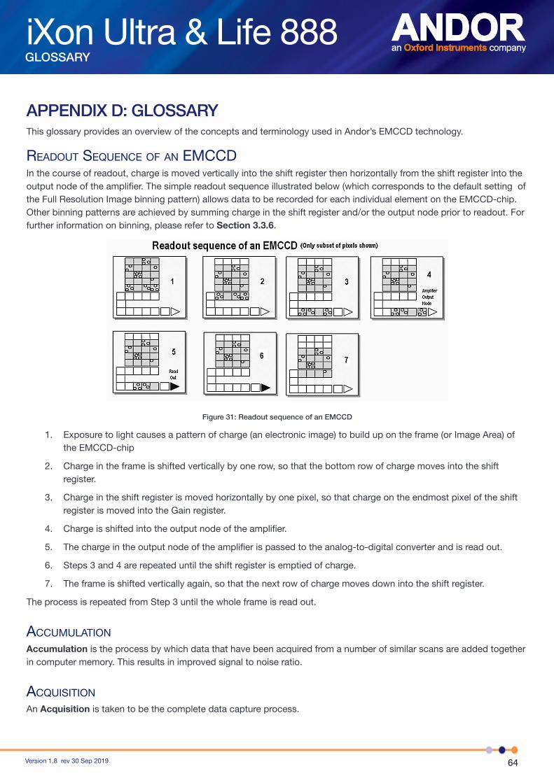
64Version 1.8 rev 30 Sep 2019
iXon Ultra & Life 888GLOSSARY
APPENDIX D: GLOSSARYThis glossary provides an overview of the concepts and terminology used in Andor’s EMCCD technology.
readout sequenCe of an emCCdIn the course of readout, charge is moved vertically into the shift register then horizontally from the shift register into the output node of the amplifier. The simple readout sequence illustrated below (which corresponds to the default setting of the Full Resolution Image binning pattern) allows data to be recorded for each individual element on the EMCCD-chip. Other binning patterns are achieved by summing charge in the shift register and/or the output node prior to readout. For further information on binning, please refer to Section 3.3.6.
Figure 31: Readout sequence of an EMCCD
1. Exposure to light causes a pattern of charge (an electronic image) to build up on the frame (or Image Area) of the EMCCD-chip
2. Charge in the frame is shifted vertically by one row, so that the bottom row of charge moves into the shift register.
3. Charge in the shift register is moved horizontally by one pixel, so that charge on the endmost pixel of the shift register is moved into the Gain register.
4. Charge is shifted into the output node of the amplifier.
5. The charge in the output node of the amplifier is passed to the analog-to-digital converter and is read out.
6. Steps 3 and 4 are repeated until the shift register is emptied of charge.
7. The frame is shifted vertically again, so that the next row of charge moves down into the shift register.
The process is repeated from Step 3 until the whole frame is read out.
aCCumulation
Accumulation is the process by which data that have been acquired from a number of similar scans are added together in computer memory. This results in improved signal to noise ratio.
aCquisition
An Acquisition is taken to be the complete data capture process.
65Version 1.8 rev 30 Sep 2019
iXon Ultra & Life 888GLOSSARY
a/d ConVersion
Charge from the EMCCD is initially read as an analogue signal, ranging from zero to the saturation value. A/D conversion changes the analogue signal to a binary (digital) number, which can then be manipulated by the computer.
baCkground
Background is a data acquisition made in darkness. It is made up of fixed pattern noise, and any signal due to dark current.
binning
Binning is a process that allows charge from two or more pixels to be combined on the EMCCD-chip prior to readout.
Counts
Counts refer to the digitization by the A/D conversion and are the basic unit in which data are displayed and processed. Depending on the particular version of the detection device, one count may, for example, be equated with a charge of 10 photoelectrons on a pixel of the EMCCD.
dark signal
Dark signal, a charge usually expressed as a number of electrons, is produced by the flow of dark current during the exposure time. All CCDs produce a dark current, an actual current that is measurable in (typically tenths of) milliamps per pixel. The dark signal adds to your measured signal level, and increases the amount of noise in the measured signal. Since the dark signal varies with temperature, it can cause background values to increase over time. It also sets a limit on the useful exposure time. Reducing the temperature of the EMCCD reduces dark signal (typically, for every 7ºC that temperature falls, dark signal halves). EMCCD readout noise is low, and in order not to compromise this by shot noise from the dark signal, it is important to reduce the dark signal by cooling the detector. If you are using an exposure time of less than a few seconds, cooling the detector below 0ºC will generally remove most of the shot noise caused by dark signal.
deteCtion limit
The Detection Limit is a measure of the smallest signal that can be detected in a single readout. The smallest signal is defined as the signal whose level is equal to the noise accompanying that signal, i.e. a Signal to Noise ratio (S/N) of unity. Sources of noise are as shown hereunder:
• Shot noise of the signal itself
• Shot noise of any dark signal
• Readout noise
If the signal is small, we can ignore its shot noise. Furthermore, if a suitably low operating temperature and short exposure time can be achieved, the lowest detection limit will equal the readout noise.
exposure time
The Exposure Time is the period during which the EMCCD collects light prior to readout.

66Version 1.8 rev 30 Sep 2019
iXon Ultra & Life 888GLOSSARY
frame transfer
Frame transfer is a special acquisition mode that is only available if your system contains a Frame Transfer (FT) CCD or EMCCD. The iXon Ultra has an FT EMCCD acquisition mode. An FT CCD or EMCCD differs from a standard CCD or EMCCD in 2 ways. Firstly, it contains 2 areas of approximately equal size as shown below:
1. The first area is the Image Area, which is located at the top and farthest from the readout register. This is the light sensitive area of the CCD.
2. The second section is the Storage Area, and is located between the Image Area and the readout register. This section is covered by an opaque mask, usually a metal film, and hence is not sensitive to light.
Figure 32: Frame transfer
The second way in which a FT CCD differs from a standard CCD is that the Image and Storage areas can be shifted independently of each other. These differences allow FT capable CCD or EMCCD devices to be operated in a unique mode where one image can be read out while the next image is being acquired. It also allows a them to be used in imaging mode without a shutter. Note: This is only applicable when the camera is running in Accumulate or Kinetic mode.
noise
pixel noise
The Pixel Noise is the variation in the pixel’s charge level when exposed to a constant signal flux over a significantly valid period of read levels. The pixel noise is normally expressed as the value of the Root Mean Square (rms) of these variations.
NOTE: The rms value is approximately x 4 to x 6 smaller than the peak to peak variations in the level values read from the pixel.
Pixel Noise has three main constituents:
• Readout noise
• Shot noise from the dark signal
• Shot noise from the light signal itself
Shot noise cannot be removed due to the laws of Physics. Most simply defined, shot noise is the squareroot of the signal (or dark signal) measured in electrons.

67Version 1.8 rev 30 Sep 2019
iXon Ultra & Life 888GLOSSARY
readout noise
Readout noise is due to the amplifier and electronics. It is independent of dark signal and signal levels, and is only very slightly dependent on temperature. It is present on every readout, as a result of which it sets a limit on the best achievable noise performance.
sHot noise Shot Noise is due to the basic laws of physics and cannot be removed. Any signal, whether it is a dark signal or a light signal, will have shot noise associated with it. Shot noise is a statistical variation in signal level which follows a Poisson distribution. The shot noise relates to the generating signal by the following relationship:-
If the signal or dark signal = N electrons, then the shot noise is the square root of N.
You can do nothing about the shot noise of your signal, but by choosing minimum exposures and operating the EMCCD at suitably low temperatures, the dark signal, and consequently the noise from the dark signal, can be reduced.
sHot noise from tHe signal
Shot noise from the signal is caused by dependence on the signal generated by the light falling onto the sensor.
sHot noise from tHe dark signal
Shot noise from the dark signal is related to the electrons generated within the sensor, Dark Current etc. Therefore it is dependent on the exposure time and it is very dependent on the temperature.
CalCulation of total pixel noise
The total pixel noise is not simply the sum of the three main noise components (readout noise, shot noise from the dark signal and shot noise from the signal). Rather, the rms gives a reasonable approximation - thus:
Total = sqrt (readnoise² + darkshot² + sigshot²)where:
• total is the pixel noise
• readnoise is the readout noise
• darkshot is the shot noise of the dark signal
• sigshot is the shot noise of the signal
fixed pattern noise
Fixed Pattern Noise (FPN) consists of the differences in count values read out from individual pixels, even if no light is falling on the detector. These differences remain constant from read to read. The differences are due in part to a variation in the dark signal produced by each pixel, and in part to small irregularities that arise during the fabrication of the EMCCD and in part to settling time of the electronics. Since fixed pattern noise is partly due to dark signal, it will change if the temperature changes but, because it is fixed, it can be completely removed from a measurement by background subtraction.

68Version 1.8 rev 30 Sep 2019
iXon Ultra & Life 888GLOSSARY
quantum effiCienCy/speCtral response
The glossary refers to signals as a number of electrons. Strictly speaking, these are “photoelectrons” created when a photon is absorbed. When a UV or visible photon is absorbed by the detector it can, at best, produce only one photoelectron. Photons of different wavelengths have different probabilities of producing a photoelectron, and this probability is usually expressed as Quantum Efficiency (QE) or Spectral Response.QE is a percentage measure of the probability of a single photon producing a photoelectron, while spectral response is the number of electrons that will be produced per unit photon energy. Many factors contribute to the QE of a EMCCD, but the most significant factor is the absorption coefficient of the silicon that serves as the bulk material of the device.
readout
Readout is the process by which data are taken from the pixels of the EMCCD and stored in computer memory. The pixels, which are arranged in a single row, are read out individually in sequence. Readout involves amplifying the charge on each pixel into a voltage, performing an analog to digital conversion and then storing the data in computer memory. The time taken to perform this operation is known as the “read time”.
saturation
Saturation is the largest signal the EMCCD can measure. A signal is measured in terms of the amount of charge that has built up in the individual pixels on the EMCCD-chip. A number of factors determine the maximum amount of charge that the EMCCD can handle.
sCans (keep Clean and aCquired)The EMCCD is continually being “scanned” to prevent its becoming saturated with dark current (see Appendix Dark Signal).
• If the scan is being used simply to “clean” the EMCCD (i.e. it is a keep-clean scan), the charge from the EMCCD is discarded
• In an acquired scan, however, the charge undergoes analog to digital conversion and is acquired into computer memory so that it can be used for subsequent processing and display: it is “read out” (see Readout above)
Unless the context specifically indicates otherwise, “scan”, in this User Guide, generally refers to an acquired scan.
sHift register
The Shift Register usually consists of a single row of elements (or pixels) running parallel to, and below, the bottom row of light-gathering pixels (the image area) on the EMCCD-chip. The shift register is protected from light by an aluminium mask. The elements in the shift register have a greater capacity to store charge (i.e. a greater “well depth”) than the other pixels on the EMCCD-chip.
signal to noise ratio
The Signal to Noise Ratio (commonly abbreviated as S/N or SNR) is the ratio between a given signal and the noise associated with that signal. Noise has a fixed component and a variable component (shot noise), which is the square root of the signal. Thus, the S/N usually increases (improves) as the signal increases.
The maximum S/N is the ratio between the maximum signal (i.e. the saturation level) and the noise associated with that signal. At near saturation levels the dominant source of noise is the shot noise of the signal.

69Version 1.8 rev 30 Sep 2019
iXon Ultra & Life 888OTHER INFORMATION
APPENDIX E: OTHER INFORMATIONterms and Conditions of sale and Warranty information
The terms and conditions of sale, including warranty conditions, will have been made available during the ordering process. The current version may be viewed at: http://www.andor.com/pdfs/literature/Andor_Standard_Warranty.pdf
Waste eleCtroniC and eleCtriCal equipment regulations 2006 (Weee)
The company’s statement on the disposal of WEEE can be found in the Terms and Conditions

70Version 1.8 rev 30 Sep 2019
iXon Ultra & Life 888OTHER INFORMATION