pressure & temperature instruments
TRANSCRIPT

PTC-0218PTC-0218
Measuring your world since 1965 TM
PRESSURE & TEMPERATURE INSTRUMENTS
PTC-0218

PTC-0218
VISIT OUR WEBSITE
.COMINSTRUMENTS
Pressure Gauges | Bimetal Thermometers | Dual Mode Thermometers | Thermocouples & RTDs Thermowells | Diaphragm Seals | Differential Gauges | Sanitary RTDs | Sanitary Gauges
ONLINE PRODUCT CONFIGURATORS
LIST PRICING PART NUMBERS
3D DRAWINGS
“The configurator is awesome! Never worked with something so easy and user friendly and
able to send pdf’s of the quote. I like this!”REOTEMP Distributor, Southeastern U.S.
“Love the Configurator, so easy to use and quick!” REOTEMP Distributor, Southern U.S.
DATA SHEETSINSTRUMENTS
Measuring your world since 1965
®
Ph: (858) 784-0710 [email protected] reotemp.com7 858-784-0710 [email protected] reotemp.comPCAT-0316
0411167
Series PT45
4.5” INDUSTRIAL PROCESS GAUGE
ww
w.www
Construction Materials: Non Wetted Case: Reinforced Thermoplastic (Phenolic) or 316SS Ring: Phenolic Turret Twist-Off or SS Twist-Off Bayonet Dial: White Aluminum, Black Letters Wetted Tube: 316LSS(Seamless), Socket: 316SS Case-to-Socket O-Ring Lens Tempered Safety Glass, Plastic, or Laminated Safety ` GlassTemperature Limits: Ambient
Process
Process Temperature Limits When Assembled with a Diaphragm Seal
Direct Mount
Remote Mount or Cooling Tower *Exact temperature limits will depend on diaphragm seal & fill fluid.
Accuracy: ±0.5%, Grade 2A (10k - 20k psi = 1% upscale, 3% downscale)Fillable: YesRestrictor Screw: Yes, removableWeight: Phenolic (Dry) = 2.5 lbs Phenolic (Filled) = 3.5 lbs SS (Dry) = 2 lbs SS (Filled) = 3 lbsMaximum Working Pressure: Stable = 100% Momentary = 130% of scale
• Safety Pattern Design• Solid Front/Blowout Back Safety Case• All Stainless Steel Internal Parts• Internal Overload and Underload Stops• Field Fillable Case• Micro-Adjustable Pointer with Floating Zero
REOTEMP’s Series PT45 process gauge is designed to withstand corrosive atmospheres and media, pulsation and vibration; a very rugged gauge engineered for the process industries. The solid front and blowout back provides a high degree of user safety. Note: For highly-corrosive, high-temperature, or severe service applications a diaphragm seal is recommended.
*dimensions in inches
PT45P
PT45T
PT45P
PT45T *dimensions in inches
-40°F 150°F
-40°F 250°F
-60°F 400°F
-100°F 750°F
1.20
PT45T Mounting Flange
Fillable Accuracy Custom Logo
FEATURES / BENEFITS
SPECIFICATIONS
Dials
™ +Diaphragm Seal
Compatible
1
1
2
2
3
3
4
4
A A
B B
C C
D D
CUSTOMER'S NAME:
CUSTOMER'S P.O. NO.:
CERTIFIED BY: DATE:
PART NO:
FIRST USED ON:
SIZE:
C
SCALE:
24793CAGE CODE: DWG NO:
FILE NAME: SHEET OF
REV:
APPROVED:
MNeillDRAWN BY:
DATE:UNLESS OTHERWISE SPECIFIEDDIMENSIONS ARE IN INCHES & [mm]TOLERANCES ARE: FRACTIONS DECIMALS ANGLES
±1/32 .X ± .2 ±5 .XX ± .01 .XXX ± .005
SURFACE FINISH
PART NAME:
REOTEMP Instrument Corporation10656 Roselle Street
San Diego, CA 92121 USAPhone: (858) 784-0710Fax: (858) 784-0720
THIS DRAWING AND SPECIFICATIONS ARE THE PROPERTY OF REOTEMP INSTRUMENT CORP., AND ARE ISSUED IN STRICT CONFIDENCE AND SHALL NOT BE REPRODUCED, COPIED OR USED AS THE BASIS FOR MANUFACTURE OR SALE OF ITEMS DEPICTED HEREIN WITHOUT WRITTEN PERMISSION FROM REOTEMP INSTRUMENT CORP.
REV DESCRIPTION
REVISIONS
DATE APPROVED
5" ADJUSTABLE ANGLE W/ RESET,1/2" NPT, Ø1/4" x 6" STEM
AJJ0601
NTS 1 1
8/28/15
A INITIAL RELEASE 8/28/15
63
REOTEMP ORDER NO.:
NOTE 1
NOTE 2
NOTE 3
NOTE 4
NOTE 5
3rd ANGLE PROJECTION
5.0 [127]
2.4 [61]
6.0 [152]
1/2" NPT
.875" FLAT TO FLAT
3.0 [75]
.3 [7]
.25 [6.4]
RESET SCREW
• LEAD TIME• 3D MODELS• CHECK STOCK• 2D DRAWINGS• E-MAIL QUOTES• PRODUCT PHOTOS
1
1
2
2
3
3
4
4
A A
B B
C C
D D
CUSTOMER'S NAME:
CUSTOMER'S P.O. NO.:
CERTIFIED BY: DATE:
PART NO:
FIRST USED ON:
SIZE:
C
SCALE:
24793CAGE CODE: DWG NO:
FILE NAME: SHEET OF
REV:
APPROVED:
MNeillDRAWN BY:
DATE:UNLESS OTHERWISE SPECIFIEDDIMENSIONS ARE IN INCHES & [mm]TOLERANCES ARE:
FRACTIONS DECIMALS ANGLES
±1/32 .X ± .2 ±5.XX ± .01.XXX ± .005
SURFACE FINISH
PART NAME:
REOTEMP Instrument Corporation10656 Roselle Street
San Diego, CA 92121 USAPhone: (858) 784-0710Fax: (858) 784-0720
THIS DRAWING AND SPECIFICATIONS ARE THE PROPERTY OF REOTEMPINSTRUMENT CORP., AND ARE ISSUED IN STRICT CONFIDENCE AND SHALL NOTBE REPRODUCED, COPIED OR USED AS THE BASIS FOR MANUFACTURE ORSALE OF ITEMS DEPICTED HEREIN WITHOUT WRITTEN PERMISSION FROMREOTEMP INSTRUMENT CORP.
REV DESCRIPTION
REVISIONS
DATE APPROVED
PT45 1/2" NPT BOTTOM CONNECT
X1
NTS 1 1
8/4/15
X1 INITIAL RELEASE 8/4/15
NOTE 1
NOTE 2
NOTE 3
NOTE 4
NOTE 5
63
REOTEMP ORDER NO.:
3rd ANGLE PROJECTION
R2.9 [75]
.9 [22]
4.0 [101]
5.1 [128]
1.0 [26]
3.4 [85]
4.1 [105]
1.7 [44]
1/2" NPT
6.9 [176]
7/8" SQUARE
3 HOLES Ø.24 [6]EQUALLY SPACED 120° ON
A Ø5.4 BOLT CIRCLE
PT45P1A2P21-D-T

(800) 648-7737 [email protected] reotemp.com
INSTRUMENTSMeasuring your world since 1965
®
PTC-0218PTC-0218
REOTEMP is a globally recognized ISO 9001 manufacturer of temperature and pressure instrumentation. REOTEMP sells through a mature distribution network that reaches all 50 states and 30 countries worldwide. We provide bimetal thermometers, pressure gauges, diaphragm seals, RTDs, thermocouples, pressure transmitters, compost thermometers, and related accessories to a
variety of process markets worldwide.
Our reputation is built on high quality products, quick standard lead times, and exceptional customer support. We are dedicated to providing our customers with complete satisfaction, from the first phone call to the design and quality of the instrument they receive. REOTEMP provides both standard and application specific products and is ready and willing to find a solution to all of your temperature and pressure needs.
San Diego Headquarters10656 Roselle St.San Diego, CA 92121United States
Houston Branch8787 West Road, Suite 140Houston, TX 77064United States
CONTACT INFORMATION
About Us
PhoneU.S. (800) 648-7737Int’l +1 (858) 784-0710Fax (858) 784-0720
INSTRUMENTSMeasuring your world since 1965
®
(800) 648-7737 [email protected] reotemp.com

(800) 648-7737 [email protected] reotemp.com
INSTRUMENTSMeasuring your world since 1965
®
PTC-0218
Table of Contents
Pressure Gauges1 Pressure Gauge Introduction3 PR Heavy-Duty Repairable Stainless Gauge7 PT 4.5” Industrial Process Gauge9 MS8 All-Welded Process Seal Gauge11 PI Hinge-Front Industrial Process Gauge13 PCS All Stainless Steel Low Pressure Gauge15 PC45 4.5” Low Pressure Capsule Gauge17 PC25N2/S2 2.5” Low Pressure Capsule Gauge19 SG Sanitary Pressure Gauge21 PM Industrial Stainless Steel Gauge25 PG Industrial Stainless/Brass Gauge27 PG25/40S Repairable Stainless/Brass Gauge31 PD General Purpose Gauge35 PL Industrial Test Gauge37 D40/42 Diaphragm Type Differential Gauge
39 D20 Piston Type Mechanical Differential Pressure Gauge
41 D05/06/09 High-Accuracy Industrial Differential Pressure Gauge
45 Pressure Gauge Range Codes & Options
Diaphragm Seals52 Diaphragm Seal Introduction55 Smart Transmitter Attachment Options57 Instrument Mounting Configurations58 Fill Fluid Guide59 W51/W61 Threaded Offline Welded Diaphragm Seals
61 T51/V51/T61 Threaded Offline Non-Metallic Diaphragm Seals
63 W5/W6 Flanged Offline Welded Diaphragm Seals65 T5/T6/V5 Flanged Offline Non-Metallic Diaphragm Seals67 W71 High Accuracy Threaded Diaphragm Seals69 W7 High Accuracy Flanged Diaphragm Seals71 W9F Flanged Flush Face Diaphragm Seals73 W9XT Extended Diaphragm Seal74 W9FP Flush Pancake (Wafer) Diaphragm Seal75 DSTF Threaded Flush Face Diaphragm Seals76 OR Isolation Ring Flow Thru Seal77 MS Welded Mini-Seal79 DSTC Sanitary Tri-Clamp® Diaphragm Seal80 DSTP Sanitary Tank Spud81 Diaphragm Seal Accessories & Options
INSTRUMENTSMeasuring your world since 1965
®
Instrument Valves & Manifolds85 Valve Introduction & Mounting Guide87 G1 Single Valve Block & Bleed88 G2 2-Valve Block & Bleed89 G3 Double Block & Bleed90 G4 Multiport Block & Bleed91 N1 Needle Valves92 M2 2-Valve Manifold93 M3 3-Valve Manifold95 M5 5-Valve Manifold97 Valve Temperature Ratings & Options
Pressure Transmitters & Switches99 Transmitter Introduction101 TG General Purpose Transmitter102 TM Compact OEM Transmitter103 TE Explosion Proof Transmitter 104 TH Heavy Duty Industrial Transmitter105 TS Sanitary Pressure Transmitter107 TL Submersible Level Transmitter108 Transmitter Range Codes & Info109 PS Mechanical Pressure Switch

(800) 648-7737 [email protected] reotemp.com 5
INSTRUMENTSMeasuring your world since 1965
®
PTC-0218PTC-0218
Table of ContentsINSTRUMENTS
Measuring your world since 1965
®
Accessories111 STW & RTR Cooling Towers112 PXS Snubbers113 PXS Siphons
Remote Reading Thermometers145 DTR Remote Digital Thermometer/Transmitter
147 Sanitary Remote Digital Thermometer/Transmitter
149 V Vapor Actuated Thermometer152 G Gas-Actuated Thermometer
155 45GW/45GF/45GFF/45GAW Direct Drive Remote Thermometer
157 45GR/45LR Direct Drive All Angle Thermometer158 9VS Liquid-in-Glass Industrial Thermometer
Thermowells160 ST/LG Threaded Thermowells162 SW/SWL/WI/WIL Welded Thermowells164 Flanged Thermowells166 STF Sanitary Thermowells168 REOTEMP Product Warranty
Dial Indicating Thermometers115 AA/CC/BB Back Connect Bimetal Thermometer117 LL/MM/JJ Adjustable Angle Bimetal Thermometer119 XR/YY/VR Bottom Connect Bimetal Thermometer121 Sanitary Bimetal Thermometer123 DMT/DM4 Dual Mode Thermometer125 DMN/DMC/DMS Navy Type Dual Mode Thermometer127 AN/XN Heavy-Duty Navy Type Thermometer129 DTA/DTX Digital Thermometer/Transmitter
131 DTL Adjustable Angle Digital Thermometer/Transmitter
133 Sanitary Digital Thermometer/Transmitter135 BT Handheld Digital Thermometer137 QQ/GG/HH Small Dial Bimetal Thermometers139 Bimetal Options141 Bimetal Range Codes142 SUR Surface Thermometer142 K79 Pocket Thermometer
143 AO/CO/BO/LO/MO/JO/ XO/YO/VO O-Temp OEM Thermometers

(800) 648-7737 [email protected] reotemp.com1
PRESSURE GAUG
ES
INSTRUMENTSMeasuring your world since 1965
®
PTC-0218(800) 648-7737 [email protected] reotemp.com1
All pressure gauge components should be selected after consideration of the pressure, temperature, media characteristics, and environmental factors. Misapplication or improper installation can cause gauge failure, which can result in damage to other equipment or personal injury. We suggest that users of pressure gauges become familiar with ASME B40.100 which is available at www.asme.org.
To ensure safety, accuracy, and gauge life, good practice requires the consideration of the following factors when selecting a pressure gauge:
1. Pressure RangeREOTEMP gauges can measure pressures from full vacuum to 30,000 psi and gauge and differential pressures as low at 10 inches of water column. Generally, a range of twice the working pressure is recommended with a maximum working pressure not to exceed 75% of scale. If pulsation occurs or media temperature is elevated, then working pressure should be at or below 50% of scale.
REOTEMP Pressure Gauges, manufactured under ISO 9001 quality standards, are offered in a wide variety of sizes, ranges, and configurations to meet the demands of any application. From the most rugged process gauges to the cost effective general purpose gauge, you can count on REOTEMP pressure gauges for long and reliable service.
INSTRUMENTSMeasuring your world since 1965
®
PRESSURE GAUGES
PTC-0218

(800) 648-7737 [email protected] reotemp.com 2
INSTRUMENTSMeasuring your world since 1965
®PRESSURE G
AUGES
PTC-0218PTC-0218PTC-0218 (800) 648-7737 [email protected] reotemp.com 2
PRESSURE GAUG
ES
Most bourdon tube and capsule gauges can see momentary spikes of 130% of scale without permanent damage to the gauge (see data sheets for specific max working pressure). Information on gauge burst pressure is available under the “Resources” tab at reotemp.com
2. Process MediaAll pressure gauge wetted components should be selected to suit the characteristics of the fluid being measured. Consider the following process media characteristics:
Temperature – Specific temperature limits are stated on the gauge data sheets. For media temperatures beyond the gauge limits a diaphragm seal or cooling element should be considered. For steam service a pigtail siphon should be used.
Corrosion – All wetted materials of the pressure gauge are noted on the data sheet. If the process fluid is not compatible with those materials then another gauge should be selected or a diaphragm seal should be installed.
Clogging – The pressure gauge socket and bourdon tube have small orifices that will clog in the presence of solids or high viscosity fluids. A diaphragm seal is recommended for these applications.
Pulsation – A mechanical pressure gauge is uniquely susceptible to the damaging effects of pulsation in a process. Most REOTEMP pressure gauges have restrictor screws (throttle plugs) installed in order to dampen some pulsation. Snubbers can be used to further dampen some types of pulsation. A diaphragm seal with the PulsePlus™ feature is recommended for severe applications.
3. Environmental FactorsThe case style, material, and design of the pressure gauge should be selected to suit the environment of the gauge installation. The environmental factors to consider include:
Vibration – Mechanical pressure gauge components are highly susceptible to vibration. Liquid filling of the case is recommended in most applications where vibration exists. In cases of severe vibration the gauge may need to be remotely mounted using flexible capillary tubing with or without a diaphragm seal.
Ambient Temperatures – Most REOTEMP pressure gauges are rated for normal ambient temperatures for outdoor installations in most parts of the globe (-40 to 140°F). If the gauge is liquid filled, care should be taken in selecting the
right fill fluid for the ambient conditions.
Moisture and Corrosion – The presence of moisture, wash-down chemicals, salt water, and other environmental factors should be considered when selecting case style and material. In high humidity environments, liquid filling the case will avoid condensation buildup on the inside of the lens.
4. Accuracy REOTEMP pressure gauges are available in accuracies ranging from 0.25% (ASME Grade 3-A) to +/- 3/2/3% (ASME Grade B). As a general rule, 1% or better gauges are used in critical process and require more costly components and larger dial sizes. All REOTEMP pressure gauges are calibrated to the stated accuracy at the time of manufacture; further certification and logging of point data can be provided on NIST traceable reference equipment.
5. Connection Size and MountingMost REOTEMP gauges come standard with ¼” or ½” Male NPT process connections. Many other connection types are available including BSP, coned high pressure fittings, SAE, tube stub, VCR, and more.
The following mounting methods are most common for pressure gauges:- Bottom Mount (stem mount)- Rear Mount (lower back or center back connection based on model)- Wall Mount (includes a back flange attached to the gauge)- Panel Mount (includes a front flange or u-clamp attached to the gauge)
6. Dial SelectionREOTEMP pressure gauges are available in dial sizes ranging from 1.5” to 6”. Typically, space consideration, accuracy, and readability are the driving factors behind dial size selection. For pressure gauges being installed into low-light or difficult to read environments, a Hi-Vis™ dial is recommended. Color bands, dual scales, tag numbers, and custom text are other options when selecting a pressure gauge for a specific application.
PTC-0218

(800) 648-7737 [email protected] reotemp.com3
PRESSURE GAUG
ES
INSTRUMENTSMeasuring your world since 1965
®
PTC-0218
Series PR25/35
HEAVY-DUTY REPAIRABLE STAINLESS GAUGE
REOTEMP’s Series PR gauge offers rugged, all-welded stainless steel construction ideal for heavy-duty industrial applications. The stainless steel case, tube and socket are welded together for superior case sealing and gauge integrity. The twist-off bayonet ring offers easy access for field repair and calibration services. Liquid filling (at the factory or in the field) is recommended for applications involving vibration.
• All-Welded Stainless Steel Construction• Removable Bayonet Ring with Adjustable Pointer• Field Fillable Case, NEMA 4X/IP65• Rugged, Long-Lasting Design
PR25
PR35
*dimensions in inches
*dimensions in inches
PR25 PR35
PR35 Mounting FlangePR25 Mounting Flange
FEATURES / BENEFITS
SPECIFICATIONS
Fillable Custom LogoDials
™ +Diaphragm Seal
Compatible
Accuracy 2 - 1 - 2%, ASME Grade A (2% up, 4% down for 10,000 psi and higher).
Ambient Limits -40°F/150°F
Process Limits -40°F/250°F
Process Limits with Diaphragm Seal
-60°F/400°F (Direct Mount)*-110°F/750°F (Remote Mount or Cooling Tower)**Exact limits depend on diaphragm seal and fill fluids.
Wetted Materials Tube: 316SS SeamlessSocket: 316SS
Lens Tempered Safety Glass , Plastic or Laminated Safety Glass
Other Materials Case: 304SSRing: 304SS Twist-Off BayonetDial: White Aluminum with Black LettersCase-Socket: Welded
Fillable Yes
Restrictor Screw Yes, removable.
Maximum Working Pressure
Stable = 100%Momentary = 130% of scale
Environmental Protection
NEMA 4X/IP65
Weight 2.5” = 0.4 lbs (0.6 lbs filled), 3.5” = 0.7 lbs (1.0 lbs filled)

(800) 648-7737 [email protected] reotemp.com 4
INSTRUMENTSMeasuring your world since 1965
®PRESSURE G
AUGES
PTC-0218PTC-0218
ü Check Stockü Configure Part #
ü Get Priceü Download PDF Data SheetsVisit reotemp.com
Series PR25/35
HEAVY-DUTY REPAIRABLE STAINLESS GAUGE
Diaphragm Seal Suitability GuideFor applications where a diaphragm seal is required, the following diaphragm seal model types are most commonly assembled and filled to Series PR25/35 pressure gauges. This matrix identifies which diaphragm seal is appropriate based on the specified pressure range. Please reference the diaphragm seal data sheet and seal fill fluid guide for additional application considerations including max pressure, temperature limits, and material compatibility.
HOW TO ORDER: Choose options to build a part number. For example: PR25S1A4P18-D-P-MP
PR25 S 1 A 4 P18 -D -P -MP
OPTIONS
-MP = Max. Pointer (Available on 2.5” ONLY)
-C3 = 3 Point Calibration Certificate
-R1 = 1% Full Scale Accuracy
-HV = Hi-Vis™ Dial-NC = NACE
Compliance Certificate
-PM = Positive Material Identification Certification
DIALSIZE
PR25 = 2.5”PR35 = 3.5”
CASETYPE
S = 304SS*T = 316SS
TUBE & SOCKET
1 = 316SS*3 = Monel
MOUNTTYPE
A = Bottom
B = Bottom/Rear Flange
C = Center Back
D = Center Back “U” Clamp
E = Center Back/Front Flange
CONNECTION
4 = 1/4” NPT*8 = 1/8” NPT 2 = 1/2” NPT (PR35 ONLY)*M = 1/4” Tube
Fitting
RANGECODE
Common RangesP01 = -30 inHg-0 psiP03 = -30 inHg- 0-30 psiP16 = 0-30 psiP18 = 0-100 psiP20 = 0-200 psiP21 = 0-300 psiP25 = 0-1,000 psiP34 = 0-5,000 psi
Available Ranges Vac to 15,000 PSI Gauge Pressure, Vac
or Compound Lowest Range = 10 psi
For Additional Range Codes See Page 45
CASEFILL
-D = Dry -G = Glycerin-S = Silicone-W = Glycerin/
Water (65/35)
-I = Inert
LENS
-T = Tempered Safety Glass (std. on 3.5”)
-P = Plastic (std. on 2.5”)-S = Laminated
Safety Glass
15 30 45 60 75 100 160 200 +
MS4 T T T
MS6 T
MS8
1/2” X S S T T T T
3/4” X T T T T T
1” T T T
1.5”
W5
T5
3/4” TC X S S T T T T
1.5” TC T T
2” TC
Mini Seals
Threaded Flush
Offline
Sanitary
Total Gauge Span* (in psi)Diaphragm Seal Model
*Total gauge span is additive of negative and positive pressures.
Example: -15 - 0 - 30 psi = 45 psi span
Assembly will function correctly with minimal accuracy degradation.
Assembly will function correctly given stable temperature.
Assembly is highly sensitive to orientation and temperature variance. REOTEMP cannot guarantee a stated accuracy.
Assembly will not work. The diaphragm does not displace enough fill fluid to drive the pressure gauge.
T
S
X
*Non-standard Configuration
PR25S1A4P18-D-PMS4G4F4XS-DTD-AS

(800) 648-7737 [email protected] reotemp.com5
PRESSURE GAUG
ES
INSTRUMENTSMeasuring your world since 1965
®
PTC-0218
Series PR40/60
HEAVY-DUTY REPAIRABLE STAINLESS GAUGE
• All-Welded Stainless Steel Construction • Removable Bayonet Ring, Micro Adjustable Pointer• Field Fillable Case, NEMA 4X/IP65• Internal Overload and Underload Stops, Floating Zero• Safety Blow-Out Relief
REOTEMP’s Series PR gauge offers rugged, all-welded stainless steel construction ideal for heavy-duty industrial applications. The stainless steel case, tube and socket are welded together for superior case sealing and gauge integrity. The twist-off bayonet ring offers easy access for field repair and calibration services. Liquid filling (at the factory or in the field) is recommended for applications involving vibration. For high-corrosive, high-temp, or severe service applications, a diaphragm seal is recommended.
PR40
PR60
*dimensions in inches
*dimensions in inches
PR40 PR60
1.20
1.20
1.201.20
PR60 Mounting FlangePR40 Mounting Flange
FEATURES / BENEFITS
SPECIFICATIONS
Fillable Accuracy
1%
Custom LogoDials
™ +Diaphragm Seal
Compatible
Accuracy 1%, ASME Grade 1A (10K to 20K ; 2% Upscale, 4% Downscale)
Ambient Limits -40°F/150°F
Process Limits -40°F/250°F
Process Limits with Diaphragm Seal
-60°F/400°F (Direct Mount)*-110°F/750°F (Remote Mount or Cooling Tower)**Exact limits depend on diaphragm seal and fill fluids.
Wetted Materials Tube: 316SS SeamlessSocket: 316SS
Lens Tempered Safety Glass , Plastic or Laminated Safety Glass
Other Materials Case: 304SSRing: 304SS Twist-Off BayonetDial: White Aluminum with Black LettersCase-Socket: Welded
Fillable Yes
Restrictor Screw Yes, removable.
Maximum Working Pressure
Stable = 100%Momentary = 130% of scale
Environmental Protection
NEMA 4X/IP65
Weight 4” = 1.3 lbs (2.0 lbs filled), 6” = 2.1 lbs (4.2 lbs filled)

(800) 648-7737 [email protected] reotemp.com 6
INSTRUMENTSMeasuring your world since 1965
®PRESSURE G
AUGES
PTC-0218PTC-0218
HEAVY-DUTY REPAIRABLE STAINLESS GAUGE
Series PR40/60
PR40 S 1 A 4 P01 -D -T -HV
15 30 45 60 75 100 160+
MS6 X S T T T
MS8 T T T
1” X X X S T T
1.5” T T T T
W5 S T T
W6 T
W7/T5/V5
1.5” TC X X X T T T
2” TC S T T
Diaphragm Seal Suitability GuideFor applications where a diaphragm seal is required, the following diaphragm seal model types are most commonly assembled and filled to Series PR40/60 pressure gauges. This matrix identifies which diaphragm seal is appropriate based on the specified pressure range. Please reference the diaphragm seal data sheet and seal fill fluid guide for additional application considerations including max pressure, temperature limits, and material compatibility.
Total Gauge Span* (in psi)Diaphragm Seal Model
Mini Seals
Threaded Flush
Offline
Sanitary
OPTIONS
-HV = Hi-Vis™ Dial-C3 = 3 pt.
Calibration Certificate
-OX = Cleaned for O2 Service
-TS = Stainless Steel Tag
-MP = Max. Pointer
-EC = Electrical Contacts (4" Case Only)
-P6 = Pointer Stop at 6 O’clock
-R2 = .5% Full Scale Accuracy
-NC = NACE Compliance Certificate
-PM = Positive Material Identification Certification
DIAL SIZE
PR40 = 4”PR60 = 6”
CASETYPE
S = 304SS*T = 316SS
TUBE & SOCKET
1 = 316SS*3 = Monel
MOUNT TYPE
A = Bottom
B = Bottom/Rear Flange
C = Lower Back
D = Lower Back “U” Clamp
E = Lower Back/Front Flange
F = Lower Back/Rear Flange
CONNECTION
4 = 1/4” NPT2 = 1/2” NPT5 = 1/4” Female
High Pressure (9/16” - 18 UNF)
RANGE CODE
Common RangesP01 = -30 inHg-0 psiP03 = -30 inHg- 0-30 psiP16 = 0-30 psiP18 = 0-100 psiP20 = 0-200 psiP21 = 0-300 psiP25 = 0-1,000 psiP34 = 0-5,000 psi
Available Ranges Vac to 20,000 psi Gauge Pressure, Vacu-
um, or Compound Lowest Range = 10 psi
Available Units: psi (std) bar kPa kg/cm2 ft H2O & more
For Additional Range Codes See Page 45
CASE FILL
-D = Dry -G = Glycerin-S = Silicone-W = Glycerin/
Water (65/35)
-I = Inert
LENS
-T = Tempered Safety Glass (std)
-P = Plastic-S = Laminated
Safety Glass
HOW TO ORDER: Choose options to build a part number. For example: PR40S1A4P01-D-T-HV
*Non-standard Configuration
*Total gauge span is additive of negative and positive pressures.
Example: -15 - 0 - 30 psi = 45 psi span
Assembly will function correctly with minimal accuracy degradation.
Assembly will function correctly given stable temperature.
Assembly is highly sensitive to orientation and temperature variance. REOTEMP cannot guarantee a stated accuracy.
Assembly will not work. The diaphragm does not displace enough fill fluid to drive the pressure gauge.
T
S
X
ü Check Stockü Configure Part #
ü Get Priceü Download PDF Data SheetsVisit reotemp.com

(800) 648-7737 [email protected] reotemp.com7
PRESSURE GAUG
ES
INSTRUMENTSMeasuring your world since 1965
®
PTC-0218
Series PT45
4.5” INDUSTRIAL PROCESS GAUGE
ww
w.www
• Safety Pattern Design• Solid Front/Blowout Back Safety Case• All Stainless Steel Internal Parts• Internal Overload and Underload Stops• Field Fillable Case• Micro-Adjustable Pointer with Floating Zero
REOTEMP’s Series PT45 process gauge is designed to withstand corrosive atmospheres and media, pulsation and vibration; a very rugged gauge engineered for the process industries. The solid front and blowout back provides a high degree of user safety. Note: For highly-corrosive, high-temperature, or severe service applications a diaphragm seal is recommended.
*dimensions in inches
PT45P
PT45T
PT45P
PT45T *dimensions in inches
1.20
PT45T Mounting Flange
Fillable Accuracy Custom Logo
FEATURES / BENEFITS
Dials
™ +Diaphragm Seal
Compatible
Accuracy ±0.5%, Grade 2A (10k - 20k psi = 1% upscale, 2% downscale)
Ambient Limits -40°F/150°F
Process Limits -40°F/250°F
Process Limits with Diaphragm Seal
-60°F/400°F (Direct Mount)*-110°F/750°F (Remote Mount or Cooling Tower)**Exact limits depend on diaphragm seal and fill fluids.
Wetted Materials Tube: 316SS SeamlessSocket: 316SS
Lens Tempered Safety Glass (Standard), Plastic or Laminated Safety Glass
Other Materials Case: Reinforced Thermoplastic (Phenolic) or 316SSRing: Phenolic Turret Twist-Off or SS Twist-Off BayonetDial: White Aluminum, Black Letters, Case-to-Socket: O-Ring
Fillable Yes
Restrictor Screw Yes, removable.
Maximum Working Pressure
Stable = 100%Momentary = 130% of scale
Environmental Protection
NEMA 4X/IP65
Weight Phenolic (Dry) = 2.5 lbsPhenolic (Filled) = 3.5 lbsSS (Dry) = 2 lbsSS (Filled) = 3 lbs
SPECIFICATIONS

(800) 648-7737 [email protected] reotemp.com 8
INSTRUMENTSMeasuring your world since 1965
®PRESSURE G
AUGES
PTC-0218PTC-0218
4.5” INDUSTRIAL PROCESS GAUGE
Series PT45
Total Gauge Span* (in psi)15 30 45 60 75 100 160+
MS6 X S T T T
MS8 S T T
1” X X X S S T
1.5” S S T T
W5 S T T
W6 T
T5 S T
W7/V5
Mini Seals
Threaded Flush
Offline
Diaphragm Seal Suitability GuideFor applications where a diaphragm seal is required, the following diaphragm seal model types are most commonly assembled and filled to Series PT45 pressure gauges. This matrix identifies which diaphragm seal is appropriate based on the specified pressure range. Please reference the diaphragm seal data sheet and seal fill fluid guide for additional application considerations including max pressure, temperature limits, and material compatibility.
Diaphragm Seal Model
HOW TO ORDER: Choose options to build a part number. For example: PT45P1A2P21-D-T-HV
PT45 P 1 A 2 P21 -D -T -HV
OPTIONS
-HV = Hi-Vis™ Dial-C3 = 3 pt.
Calibration Certificate
-OX = Cleaned for O2 Service
-TS = Stainless Steel Tag
-MP = Max. Pointer-EC = Electrical
Contacts**-P6 = Pointer Stop at
6 O’clock-FM = Flush Mount
Ring for Phenolic Case
-NC = NACE Compliance Certificate
-PM = Positive Material Identification Certification
DIAL SIZE
PT45 = 4.5”
CASE TYPE
P = Fiberglass Reinforced Thermo- plastic
T = 316SS, Bayonet Ring
TUBE & SOCKET
1 = 316SS*3 = Monel
MOUNT TYPE
A = Bottom
C = Lower Back
E = Lower Back / Front Flange (316SS case Only)
CONNECTION
2 = 1/2” NPT4 = 1/4” NPT5 = 1/4” Female
High Pressure (9/16” - 18 UNF)
3 = 3/4” NPT
CASE FILL
-D = Dry -G = Glycerin-T = Dry, Teflon
Coated Movement
-W = Glycerin/Water (65/35)
-S = Silicone-I = Inert
LENS
-T = Tempered Safety Glass (std)
-P = Plastic-S = Laminated
Safety Glass
RANGE CODE
Common RangesP01 = -30 inHg-0 psiP03 = -30 inHg-0-30 psiP16 = 0-30 psiP18 = 0-100 psiP20 = 0-200 psiP21 = 0-300 psiP25 = 0-1,000 psiP34 = 0-5,000 psi
Available Ranges Vac to 20,000 psi Gauge Pressure,
Vacuum, or Compound Lowest Range = 10 psi
Available Units psi bar kPa kg/cm2
ftH20 & more
For Additional Range Codes See Page 45
*Total gauge span is additive of negative and positive pressures.
Example: -15 - 0 - 30 psi = 45 psi span
Assembly will function correctly with minimal accuracy degradation.
Assembly will function correctly given stable temperature.
Assembly is highly sensitive to orientation and temperature variance. REOTEMP cannot guarantee a stated accuracy.
Assembly will not work. The diaphragm does not displace enough fill fluid to drive the pressure gauge.
T
S
X
*Non-standard Configuration**Phenolic Case Only
PT45P1A2L21-D-TW51522SSS-TTDTD-AS
ü Check Stockü Configure Part #
ü Get Priceü Download PDF Data SheetsVisit reotemp.com

(800) 648-7737 [email protected] reotemp.com9
PRESSURE GAUG
ES
INSTRUMENTSMeasuring your world since 1965
®
PTC-0218
ALL-WELDED PROCESS SEAL GAUGE
Series MS8
• Increases the Life of the Gauge by Up to 3x• Reduce/Eliminate Fugitive Emissions• Available Up to 5,000 psi• Eliminate Potential Leak Points• Tamper Resistant• Compliant to NACE MR0175, MR0103
REOTEMP’s All-Welded Pressure Seal Gauge offers superior diaphragm seal safety and performance at an economical price. Combined with a gauge or transmitter, the tamper-resistant all-welded diaphragm seal reduces potential leak points, making it ideal for installations where process integrity and worker safety are paramount. Combined with PulsePlus™ protection, the Series MS8 can potentially triple the life of your gauge or transmitter.
MS8PT
All drawings depict a 1/2” NPT Male process connection. See online configurator for specific assembly drawings.
MS8P2 MS8P4
FEATURES / BENEFITS
SPECIFICATIONS
MS8PT
MS8P2
MS8P4
Fillable Custom LogoDials
™
Accuracy With appropriate pressure range, seal gauge accuracy is gauge accuracy plus 0.5%. (May be subject to thermal error. Consult factory with questions.)
Ambient Limits -40°F/150°F
Process Limits with Diaphragm Seal
-40°F/400°F (Direct Mount)*-110°F/750°F (Remote Mount or Cooling Tower)**Exact limits depend on diaphragm seal and fill fluids.
Wetted Materials Diaphragm, Lower and Process Connection: 316LSS or Hast. C-276Gasket: None
Lens Tempered Safety Glass , Plastic or Laminated Safety Glass
Other Materials Upper Housing: 316SS
Fillable Yes
Maximum Working Pressure
See table left.
Environmental Protection
NEMA 4X/IP65
Weight 0.6 lbs (Seal Only)
DIAPHRAGM SEAL MAX WORKING PRESSURE (AT 100°F)316SS Hast. C-276 Monel
Male
1/4” NPT 5,000 psi 2,000 psi 2,000 psi1/2” NPT 5,000 psi 2,000 psi 2,000 psi3/4” NPT 2,000 psi n/a n/a1” NPT 1,000 psi n/a n/a
Female1/4” NPT 2,500 psi n/a n/a1/2” NPT 2,500 psi n/a n/a
Note: Maximum working pressure is lesser of proof pressure and 130% of gauge range.

(800) 648-7737 [email protected] reotemp.com 10
INSTRUMENTSMeasuring your world since 1965
®PRESSURE G
AUGES
PTC-0218PTC-0218
Series MS8
ALL-WELDED PROCESS SEAL GAUGE
MS8PT A M3 X P23 -S
DDD AS P G T -HV
HOW TO ORDER: Choose options to build a part number. For example: MS8PTAM3XP23-SDDDASPGT-HV
PROCESS CONNECTION
ThreadedM2 = 1/2” male NPTM4 = 1/4” male NPTM3 = 3/4” male NPTM1 = 1” male NPTF2 = 1/2” female NPTF4 = 1/4” female NPTF3 = 3/4” female NPT
FlangedR11 = 1”x150#RFR13 = 1”x300#RFRH1 = 1.5”x150#RFRH3 = 1.5”x300#RF
WETTEDMATERIAL
-S = 316L SS-H = Hast. C-276-M = Monel 400†
Note: see maximum working pressure table on previous page for available process connections.
†Furnished with Monel upper housing.
PRESSURE RANGE
Common RangesP03 = -30"inHg/0/30 psiP15 = 15 psiP16 = 30 psiP17 = 60 psiP18 = 100 psiP20 = 200 psiP21 = 300 psiP22 = 400 psiP23 = 600 psiP25 = 1,000 psiP31 = 2,000 psiP32 = 3,000 psiP34 = 5,000 psi
Available Ranges 15 psi to 6,000 psi Gauge Pressure,
Vacuum, or Compound
Standard Units psi psi/bar
Note: Minimum Span for 4" Gauges and Greater is 30 psi
For Additional Range Codes See Page 45
PRESSURE INSTRUMENT
Solid Front/ Blowout Back Process GaugesMS8PT = 4.5” Phenolic
Process MS8PS = 4.5” Stainless
Safety Gauge
Industrial All Stainless Steel GaugesMS8P6 = 6” SSMS8P4 = 4” SSMS8P3 = 3.5” SSMS8P2 = 2.5” SS
Hinged-Ring Process GaugeMS8PI = 4.5” Aluminum
Case, SS internals
GAUGE MOUNT
A = Bottom
C = Back (4”, 4.5”, 6”) Lower Back (2.5”, 3.5”) Center Back
E = Back/ Front Flange (Panel Mount) (4”, 4.5”, 6”) Lower Back (2.5”, 3.5”) Center Back
FLUSH CONNECTION
X = No FlushF = Single 1/4” Flush
(Ships with Plug Installed)
PULSATION PROTECTION
X = NoneP = Pulse Plus™
(Pulsation Protection)
OPTIONS
-HV = Hi-Vis™ Dial-C3 = 3 Point Calibration
Certificate-TS = Stainless Steel Tag-OX = Cleaned for O2
Service-CN = NACE Certificate-PM = Positive Material
Identification Certification
-MM = Monel Wetted Gauge
See Pages 50 & 83 for Additional Options
LENS
T = Tempered Safety Glass
S = Laminated Safety Glass
P = Plastic
SEAL MOUNTING
DDD = DirectRTR = Cooling TowerB?? = Armored 316 SS
Capillary (5-40 ft.) W?? = PVC Coated
Armored 316 SS Capillary
Note: ?? = Length in feet (e.g. 05 = 5 feet)
Note: Capillary connection is welded unless otherwise specified.
SEAL FILL
AS = Silicone DC200AG = GlycerinC1 = Fomblin Y06BH = Silicone DC704C2 = Halocarbon 6.3
See 58 for Complete Fill Guide
CASE FILL
D = DryG = GlycerinW = Glycerin Water
(65/35)S = SiliconeI = Inert
Note: MS8PI is not fillable.
ü Check Stockü Configure Part #
ü Get Priceü Download PDF Data SheetsVisit reotemp.com

(800) 648-7737 [email protected] reotemp.com11
PRESSURE GAUG
ES
INSTRUMENTSMeasuring your world since 1965
®
PTC-0218
HINGE-FRONT INDUSTRIAL PROCESS GAUGE
Series PI
www.
REOTEMP’s Series PI45 process gauge is designed to withstand corrosive atmospheres and media, ideal for panel builders in the heavy-industrial markets. The hinge-front case allows for easy access to the gauge dial while still panel mounted.
*dimensions in inches
PI
PI45
1.20
*dimensions in inches
1.20
Accuracy Custom Logo
Integrated PI45 Mounting Flange
Dials
™
• All Stainless Steel Internal Parts• Internal Overload and Underload Stops• Micro-Adjustable Pointer with Floating Zero• Hinge-Front Case for Easy Recalibration
+Diaphragm Seal
Compatible
7.59
1/4-20Thread
Integrated PI60 Mounting Flange
FEATURES / BENEFITS
SPECIFICATIONSAccuracy ±0.5%, ASME Grade 2A, (10k-20k psi,
1% upscale and 3% downscale)
Ambient Limits -40°F/150°F
Process Limits -40°F/250°F
Process Limits with Diaphragm Seal
-60°F/400°F (Direct Mount)*-110°F/750°F (Remote Mount or Cooling Tower)**Exact limits depend on diaphragm seal and fill fluids.
Wetted Materials Tube: 316SS SeamlessSocket: 316SS
Lens Glass (Standard on 6")Plastic (Standard on 4.5")
Other Materials Case: Black Painted AluminumRing: Black Painted AluminumDial: AluminumCase-to-Socket: O-Ring, Vented
Fillable No
Restrictor Screw Yes
Maximum Working Pressure
Stable = 100%Momentary = 130% of scale
Weight 2.5 lbs
PI60

(800) 648-7737 [email protected] reotemp.com 12
INSTRUMENTSMeasuring your world since 1965
®PRESSURE G
AUGES
PTC-0218PTC-0218
Series PI
HINGE-FRONT INDUSTRIAL PROCESS GAUGE
PI45 H 1 E 2 P16 -D -P -HV
Diaphragm Seal Suitability GuideFor applications where a diaphragm seal is required, the following diaphragm seal model types are most commonly assembled and filled to Series PI45 pressure gauges. This matrix identifies which diaphragm seal is appropriate based on the specified pressure range. Please reference the diaphragm seal data sheet and seal fill fluid guide for additional application considerations including max pressure, temperature limits, and material compatibility.
15 30 45 60 75 100 160+
MS6 X S T T T
MS8 S T T
1” X X X S S T
1.5” S S T T
W5 S T T
W6 T
T5 S T
W7/V5
Total Gauge Span* (in psi)Diaphragm Seal Model
Mini Seals
Threaded Flush
Offline
*Total gauge span is additive of negative and positive pressures.
Example: -15 - 0 - 30 psi = 45 psi span
Assembly will function correctly with minimal accuracy degradation.
Assembly will function correctly given stable temperature.
Assembly is highly sensitive to orientation and temperature variance. REOTEMP cannot guarantee a stated accuracy.
Assembly will not work. The diaphragm does not displace enough fill fluid to drive the pressure gauge.
T
S
X
HOW TO ORDER: Choose options to build a part number. For example: PI45H1E2P16-D-P-HV
OPTIONS
-HV = Hi-Vis™ Dial-C3 = 3 pt. Calibration Certificate-OX = Cleaned for
O2 Service-NC = NACE
Compliance Certificate
-PM = Positive Material Identification Certification
DIALSIZE
PI45 = 4.5”*PI60 = 6”
CASETYPE
H = Black Painted Aluminum, Hinge- Front
TUBE & SOCKET
1 = 316SS*3 = Monel
MOUNTTYPE
E = Lower Back/Front Flange
CONNECTION
2 = 1/2” NPT4 = 1/4” NPT
CASE FILL
-D = Dry
Case is not fillable.
LENS
-P = Plastic-G = Glass
RANGE CODE
Common RangesP01 = -30 inHg-0 psiP03 = -30 inHg-0-30 psiP16 = 0-30 psiP18 = 0-100 psiP20 = 0-200 psiP21 = 0-300 psiP25 = 0-1,000 psiP34 = 0-5,000 psi
Available Ranges Vac to 20,000 psi Gauge Pressure,
Vacuum, or Compound Lowest Range = 10 psi
Available Units psi bar kPa kg/cm2
ftH20 & more
For Additional Range Codes See Page 45 *Non-standard configuration
ü Check Stockü Configure Part #
ü Get Priceü Download PDF Data SheetsVisit reotemp.com

(800) 648-7737 [email protected] reotemp.com13
PRESSURE GAUG
ES
INSTRUMENTSMeasuring your world since 1965
®
PTC-0218
ALL STAINLESS STEEL LOW PRESSURE GAUGE
Series PCS
• Sensitive Diaphragm/Capsule Mechanism• All-Welded 316 Stainless Steel Capsule and
Socket• Easy-Access Zero Reset Screw on Dial
REOTEMP’s Series PC low pressure gauges offer accurate and reliable measurements of gaseous media. Offered with stainless steel internals, the Series PC is designed to withstand corrosive media and ensure a long-lasting instrument.
PC25S1
PC40S1
*dimensions in inches
*dimensions in inches
PC60S1 *dimensions in inches
PC25S1 PC40S1 PC60S1
FEATURES / BENEFITS
SPECIFICATIONS
Custom LogoDials
™ +Diaphragm Seal
Compatible
Accuracy 2 - 1.6 - 2%
Ambient Limits -40°F/150°F
Process Limits -40°F/200°F
Process Limits with Diaphragm Seal
-60°F/350°F (Direct Mount)*-110°F/750°F (Remote Mount or Cooling Tower)**Exact limits depend on diaphragm seal and fill fluids.
Wetted Materials Capsule: 316LSSSocket: 316SS
Lens Tempered Safety Glass (Standard), Plastic or Laminated Safety Glass
Other Materials Case: 304SSRing: 304SS, Bayonet Twist-OffDial: White Aluminum, Black LettersCase-to-Socket: Screw Connection, Vented Case
Fillable No
Restrictor Screw Yes
Maximum Working Pressure
Stable = 100%Momentary = 130% of scale
Weight 2.5” = 0.5 lbs4” = 1.1 lbs6” = 2.1 lbs

(800) 648-7737 [email protected] reotemp.com 14
INSTRUMENTSMeasuring your world since 1965
®PRESSURE G
AUGES
PTC-0218PTC-0218
ALL STAINLESS STEEL LOW PRESSURE GAUGE
Series PCS
PC40 S 1 A 2 -TP52 -HV-D
Diaphragm Seal Suitability Guide
High Displacement
Low pressure capsule gauges are very sensitive and require diaphragm seals with high sensitivity and high fluid displacement. If a diaphragm seal is required to isolate the process fluid from the pressure gauge, the following seal model types are avail-able for the Series PC.
10” 15” 20” 30” 40” 60” 100” 160” 200” 300”
W6 X X X X X X S S T T
W7 X X X S S T T T
V5 X S S T T T T T
T6 X X X X X S S S S S
Total Gauge Span* (in H2O)Diaphragm Seal Model
*Total gauge span is additive of negative and positive pressures.
Example: -15 - 0 - 30 psi = 45 psi span
Assembly will function correctly with minimal accuracy degradation.
Assembly will function correctly given stable temperature.
Assembly is highly sensitive to orientation and temperature variance. REOTEMP cannot guarantee a stated accuracy.
Assembly will not work. The diaphragm does not displace enough fill fluid to drive the pressure gauge.
T
S
X
DIALSIZE
PC25 = 2.5”
CAPSULE & SOCKET
1 = 316SS
MOUNT TYPE
A = Bottom
B = Bottom/Rear Flange
*C = Center Back
*D = Center Back “U” Clamp
*E = Center Back/Front Flange
CONNECTION
4 = 1/4” NPT
A = Bottom
B = Bottom/Rear Flange
*C = Lower Back
*E = Lower Back/Front Flange
RANGE CODE
Common RangesP50 = 0-10 in H2OP51 = 0-15 in H2OP52 = 0-30 in H2OP53 = 0-60 in H2OP54 = 0-100 in H2OP55 = 0-160 in H2OP56 = 0-200 in H2O
Available Ranges 10” to 300” Water
Column Gauge Pressure,
Vacuum, or Compound
Standard Units in H2O
Available Units kPa inHg mbar mmHg psi oz/in2
mmH2O & more
For Additional Range Codes See Page 46
LENS
-T = Tempered Safety Glass (Standard)-P = Plastic-S = Laminated Safety Glass
OPTIONS
-HV = Hi-Vis™ Dial-OX = Cleaned for
O2 Service-C3 = 3 pt.
Calibration Certificate
-TS = Stainless Steel Tag
-NC = NACE Compliance Certificate
-PM = Positive Material Identification Certification
-R5 = 1.5% Full Scale Accuracy (Not Available on Compound Ranges)
PC40 = 4”PC60 = 6”
CASEFILL
-D = Dry
Case is not fillable.
4 = 1/4” NPT2 = 1/2” NPT
CASETYPE
S = 304SS Case & Bezel w/ Removable Bayonet, Zero Correction on Dial
HOW TO ORDER: Choose options to build a part number. For example: PC40S1A2P52-D-T-HV
*Non-standard configuration
ü Check Stockü Configure Part #
ü Get Priceü Download PDF Data SheetsVisit reotemp.com

(800) 648-7737 [email protected] reotemp.com15
PRESSURE GAUG
ES
INSTRUMENTSMeasuring your world since 1965
®
PTC-0218
4.5” LOW PRESSURE CAPSULE GAUGE
Series PC45
• Sensitive Diaphragm/Capsule Mechanism• Safety Blowout Back• Easy-Access Zero Reset on Dial
REOTEMP’s Series PC45 low pressure capsule gauges offer accurate and reliable measurements of gaseous media. Offered with stainless steel internals, they are designed to withstand corrosive media and ensure a long-lasting instrument.
*dimensions in inches
PC45
PC45
FEATURES / BENEFITS
SPECIFICATIONS
Custom LogoDials
™ +Diaphragm Seal
Compatible
Accuracy 2 - 1.6 - 2% Full Scale
Ambient Limits -40°F/150°F
Process Limits -40°F/200°F
Process Limits with Diaphragm Seal
-60°F/350°F (Direct Mount)*-110°F/750°F (Remote Mount or Cooling Tower)**Exact limits depend on diaphragm seal and fill fluids.
Wetted Materials Capsule: 316LSSSocket: 316SS
Lens Tempered Safety Glass(Standard), Plastic or Laminated Safety Glass
Other Materials Case: Reinforced Thermoplastic, PhenolicRing: Phenolic, Twist-OffDial: AluminumCase-to-Socket: O-ring, Vented Case
Fillable No
Restrictor Screw Yes
Maximum Working Pressure
Stable = 100%Momentary = 130% of scale
Environmental Protection
NEMA 4X/IP65
Weight 2.3 lbs

(800) 648-7737 [email protected] reotemp.com 16
INSTRUMENTSMeasuring your world since 1965
®PRESSURE G
AUGES
PTC-0218PTC-0218
4.5” LOW PRESSURE CAPSULE GAUGE
Series PC45
PC45 P 1 A 4 P53 -D -T -HV
Diaphragm Seal Suitability Guide
High Displacement
Low pressure capsule gauges are very sensitive and require diaphragm seals with high sensitivity and high fluid displacement. If a diaphragm seal is required to isolate the process fluid from the pressure gauge, the following seal model types are avail-able for the Series PC.
10” 15” 20” 30” 40” 60” 100” 160” 200” 300”
W6 X X X X X X S S T T
W7 X X X S S T T T
V5 X S S T T T T T
T6 X X X X X S S S S S
Total Gauge Span* (in H2O)Diaphragm Seal Model
*Total gauge span is additive of negative and positive pressures.
Example: -15 - 0 - 30 psi = 45 psi span
Assembly will function correctly with minimal accuracy degradation.
Assembly will function correctly given stable temperature.
Assembly is highly sensitive to orientation and temperature variance. REOTEMP cannot guarantee a stated accuracy.
Assembly will not work. The diaphragm does not displace enough fill fluid to drive the pressure gauge.
T
S
X
HOW TO ORDER: Choose options to build a part number. For example: PC45P1A4P53-D-T-HV
DIALSIZE
PC45 = 4.5”
CASETYPE
P = Fiberglass Reinforced Thermoplastic
CAPSULE & SOCKET
1 = 316SS
CONNECTION
4 = 1/4” NPT2 = 1/2” NPT
RANGE CODE
Common RangesP50 = 0-10 in H2OP51 = 0-15 in H2OP52 = 0-30 in H2OP53 = 0-60 in H2OP54 = 0-100 in H2OP55 = 0-160 in H2OP56 = 0-200 in H2O
Available Ranges 10” to 300” Water Column Gauge Pressure, Vacuum,
or Compound
Standard Units in H2O
Available Units kPa inHg mbar mmHg psi oz/in2
mmH2O & more
For Additional Range Codes See Page 46
OPTIONS
-HV = Hi-Vis™ Dial-C3 = 3pt.
Calibration Certificate
-TS =Stainless Steel Tag
-FM =Flush Mount Ring for Panel Mounting
-NC = NACE Compliance Certificate
-PM = Positive Material Identification Certification
-R5 = 1.5% Full Scale Accuracy (Not Available on Compound Ranges)
CASE FILL
-D = Dry
Case is not fillable.
LENS
-T = Tempered Safety Glass (std)-P = Plastic-S = Laminated Safety Glass
MOUNT TYPE
A = Bottom
*C = Lower Back
*Non-standard configuration
ü Check Stockü Configure Part #
ü Get Priceü Download PDF Data SheetsVisit reotemp.com

(800) 648-7737 [email protected] reotemp.com17
PRESSURE GAUG
ES
INSTRUMENTSMeasuring your world since 1965
®
PTC-0218
2.5” GENERAL PURPOSE LOW PRESSURE GAUGE
Series PC25N2/S2
• Sensitive Diaphragm/Capsule Mechanism• Black Steel or Stainless Steel Case• Easy-Access Zero Reset on Dial• Economical Design for Non-Severe Service
REOTEMP’s Series PC25N2/S2 brass gauges are designed for use in low pressure applications with dry gasses that are compatible with copper alloy. Examples include: exhaust systems and blowers.
*dimensions in inchesPC25N2
PC25S2
PC25N2 PC25S2
*dimensions in inches
FEATURES / BENEFITS
SPECIFICATIONS
Custom Logo
Accuracy 3 - 2 - 3%, ASME Grade B
Ambient Limits -40°F/140°F
Process Limits -40°F/140°F
Process Limits with Diaphragm Seal
Cannot be mounted to a diaphragm seal.
Wetted Materials Capsule: Copper AlloySocket: Copper Alloy
Lens Plastic (Standard on “N” case, optional on “S” case)Glass (Standard on “S” case, not available on “N” case)
Other Materials Case: Black Painted Steel or 304SSRing: Snap-In Plastic or 304SSDial: White Aluminum, Black LettersCase-to-Socket: Screw Connection
Fillable No
Restrictor Screw No
Maximum Working Pressure
Stable = 100%Momentary = 110% of scale
Weight PC25N = .25 lbs, PC25S = .4 lbs

(800) 648-7737 [email protected] reotemp.com 18
INSTRUMENTSMeasuring your world since 1965
®PRESSURE G
AUGES
PTC-0218PTC-0218
2.5” GENERAL PURPOSE LOW PRESSURE GAUGE
Series PC25N2/S2
PC25 N 2 A 4 -D -P -TSP53
HOW TO ORDER: Choose options to build a part number. For example: PC25N2A4P53-D-P-TS
DIALSIZE
PC25 = 2.5”
CASE
N = Black Steel with Snap-In Plastic Window, Zero CorrectionS = 304 SS Case & Bezel with Removable Bayonet, Zero Correction on Dial
CAPSULE & SOCKET
2 = Copper Alloy
MOUNT TYPE
A = Bottom
*B = Bottom/ Rear Flange
C = Center Back
*D = Center Back “U” Clamp
*E = Center Back/ Front Flange
CONNECTION
4 = 1/4” NPT
RANGE CODE
Common RangesP51 = 0-15 in H2OP52 = 0-30 in H2OP53 = 0-60 in H2OP54 = 0-100 in H2OP55 = 0-160 in H2OP56 = 0-200 in H2OI55 = 0-5 psi
Available Ranges 15” to 300” Water
Column Gauge Pressure,
Vacuum, or Compound
Standard Units in H2O
Available Units kPa inHg mbar mmHg psi oz/in2
mmH2O & more
For Additional Range Codes See Page 46
OPTIONS
-TS = Stainless Steel Tag-C3 = 3 pt. Calibration Certificate
CASE FILL
-D = Dry
Case is not fillable.
LENS
-P = Plastic1
-G = Glass2
*Non-standard configuration1Standard on "N" Case
2Standard for “S” Case but Not Available on “N” Case
ü Check Stockü Configure Part #
ü Get Priceü Download PDF Data SheetsVisit reotemp.com

(800) 648-7737 [email protected] reotemp.com19
PRESSURE GAUG
ES
INSTRUMENTSMeasuring your world since 1965
®
PTC-0218
Series SG
SANITARY PRESSURE GAUGE
• Quick Connect Tri-Clamp® Design• Fast Removal and Installation of Instruments, to
Allow Flushing or Changing the Process Media• Ideal for Clean-in-Place, or Equipment Washdown• Designed to Meet 3-A Sanitary Standards• Comes Standard with 3-A Certification• All Welded 316SS Tube, Socket, Seal, and
Diaphragm
REOTEMP SG sanitary gauges are specially designed to meet the demanding safety requirements of the food, dairy, beverage, pharmaceutical, and biotech applications. They come standard with 3-A certification.
SG
SG20ATC75 2” Gauge with 3/4”
Tri-Clamp
SPECIFICATIONS
FEATURES / BENEFITS
Fillable Custom Logo
For specific assembly drawings see online configurator.
SG25ATC15 2.5” Gauge with 1.5”
Tri-Clamp
SG35ATC15 3.5” Gauge with 1.5”
Tri-ClampSG40ATC15
4” Gauge with 1.5” Tri-Clamp
Certified Dials
™
Accuracy (1.5" & Larger Tri-Clamp)
±1.5% for 100 psi and Above±2% for Vacuum, Compound and <100 psi
Accuracy (3/4" Tri-Clamp)
±2.5% Upscale±4% Downscale
Ambient Limits -40°F/130°F
Process Limits -40°F/200°F
Wetted Materials Body: 316SSInternal Parts: 316SSWetted Surface Finish: 18-24 Ra
Lens Plastic (Standard), Laminated Safety Glass, Tempered Safety Glass or Polysulfone
Other Materials Case: 304SSDial: White Aluminum, Black Letters
Fillable Yes, All Models Except SG20
Maximum Working Pressure
Stable = 100%Momentary = 130% of scale
Environmental Protection
NEMA 4X/IP65

(800) 648-7737 [email protected] reotemp.com 20
INSTRUMENTSMeasuring your world since 1965
®PRESSURE G
AUGES
PTC-0218PTC-0218
SANITARY PRESSURE GAUGE
Series SG
HOW TO ORDERHOW TO ORDER: Choose options to build a part number. For example: SG25ATC20P18-D-P-AG-PP
SG25 A 20 P18 -PP-D -AG
MODEL
SG20 = 2" Dial Sanitary Gauge
SG25 = 2.5" Dial Sanitary Gauge
SG35 = 3" Dial Sanitary Gauge
SG40 = 4" Dial Sanitary Gauge
CASE FILL
-D = Dry-G = USP
Glycerin-W = Glycerin/
Water (65/35)
-S = Silicone
SG20 is not fillable.
CONNECTION LOCATION
A = Bottom Connection
C = Back Connection (Center Back Mount, Except 4" Dial is Lower Back Mount)
L = Left Side Connection
R = Right Side Connection
T = Top Connection
CLAMPSIZE
75 = 3/4”15 = 1.5”20 = 2”25 = 2.5”30 = 3”
PRESSURE RANGE
Common RangesP01 = -30inHg-0 psiP03 = -30inHg- 0-30
psiP16 = 0-30 psiP18 = 0-100 psiP20 = 0-200 psiP21 = 0-300 psi
Available Ranges Vac to 1,000 psi Gauge Pressure,
Vacuum, or Compound
Lowest Range = 15 psi
Available Units: psi (std) bar kPa kg/cm2 ft H2O & more
For Additional Range Codes See Page 45
SEAL FILL FLUID
See 58 for Complete Fill Guide
-AG = USP Glycerin
-BN = Neobee M20
-BS = Food-grade Silicone
OPTIONS
-PP = Pulse Plus™ (Pulsation Protection)
-EP = Electropolish Diaphragm
-HC = Hastelloy C-276 Wetted Parts
-TS = SS Tag (1-10 Characters)
-HV = Hi-Vis™ Dial -MP = Max Pointer
(SG25 or SG40 Only)
-C3 = 3 Point Calibration Cert
See Pages 50 & 83 for Additional Options
Tri-Clamp® is a registered trademark of Alpha Laval Inc.
Diaphragm Seal Suitability GuideFor applications where a diaphragm seal is required, the following diaphragm seal model types are most commonly assembled and filled to Series PR25/35 pressure gauges. This matrix identifies which diaphragm seal is appropriate based on the specified pressure range. Please reference the diaphragm seal data sheet and seal fill fluid guide for additional application considerations including max pressure, temperature limits, and material compatibility.
Tri-Clamp 15 30 45 60 75 100 160 200 +
SG20
3/4" X S S T T
1.5" T
2"
SG25
3/4" X S S T T T T
1.5" T T
2"
SG35
3/4" X S S T T T T
1.5" T T
2"
SG40
3/4” X X X X X X X X
1.5” X X X T T T
2” S T T
2.5" T
Total Gauge Span* (in psi)
*Total gauge span is additive of negative and positive pressures.
Example: -15 - 0 - 30 psi = 45 psi span
Assembly will function correctly with minimal accuracy degradation.
Assembly will function correctly given stable temperature.
Assembly is highly sensitive to orientation and temperature variance. REOTEMP cannot guarantee a stated accuracy.
Assembly will not work. The diaphragm does not displace enough fill fluid to drive the pressure gauge.
T
S
X
TC
CONNECTION TYPE
TC = Tri-ClampCI = I-Line
-P
LENS
-P = Plastic-S = Laminated
Safety Glass*
-T = Tempered Safety Glass*
-F = Polysulfone Lens with Weep Hole for Autoclaving, not Available with Case Fill*
*Not Available on SG20
ü Check Stockü Configure Part #
ü Get Priceü Download PDF Data SheetsVisit reotemp.com

(800) 648-7737 [email protected] reotemp.com21
PRESSURE GAUG
ES
INSTRUMENTSMeasuring your world since 1965
®
PTC-0218
INDUSTRIAL STAINLESS STEEL GAUGE
Series PM15/20
• Stainless Steel Case and Crimped Ring • Stainless Steel Wetted Parts• Glycerin Filled or Dry/Fillable• Compact Design for Space-Limited Installation
REOTEMP’s Series PM feature a stainless steel case, tube and socket, making the gauges resistant to corrosion from both environment and media. Liquid filling is recommended for severe service. The economical and attractive crimp ring design, along with a variety of convenient panel mounting adapters, make this popular gauge the right choice for many applications.
PM20 *dimensions in inches
PM15 *dimensions in inches
PM15C1A PM15C1C
PM15 Mounting Flange
For PM20 mounting flange details, please contact REOTEMP customer service.
Fillable
FEATURES / BENEFITS
SPECIFICATIONSAccuracy 3 - 2 - 3%, ASME Grade B
Ambient Limits -40°F/140°F
Process Limits -40°F/150°F
Process Limits with Diaphragm Seal
Cannot be mounted to a diaphragm seal.
Wetted Materials Tube: 316SSSocket: 316SS
Lens Plastic (Standard) or Glass
Other Materials Case: 304SSRing: 304SSDial: White Aluminum, Black LettersCase-to-Socket: Screw Connection
Fillable Yes
Restrictor Screw Built-in, Non-Removable
Maximum Working Pressure
Stable = 100%Momentary = 110% of scale
Environmental Protection
NEMA 4X/IP65
Weight 1.5” = 0.15 lbs (0.25 lbs filled)2” = 0.30 lbs (0.4 lbs filled)

(800) 648-7737 [email protected] reotemp.com 22
INSTRUMENTSMeasuring your world since 1965
®PRESSURE G
AUGES
PTC-0218PTC-0218
INDUSTRIAL STAINLESS STEEL GAUGE
Series PM15/20
PM15 C 1 A 8 P16 -G -P -TS
HOW TO ORDER: Choose options to build a part number. For example: PM15C1A8P16-G-P-TS
DIALSIZE
PM15 = 1.5”PM20 = 2”
CASE TYPE
C = 304SS, Crimped Ring
TUBE & SOCKET
1 = 316SS
MOUNT TYPE
A = Bottom
C = Center Back
D = Center Back “U” Clamp
E = Center Back/ Front Flange
CONNECTION
8 = 1/8” NPT4 = 1/4” NPT
RANGE CODE
Common RangesP16 = 0-30 psiP17 = 0-60 psiP18 = 0-100 psiP19 = 0-160 psiP20 = 0-200 psiP21 = 0-300 psiP23 = 0-600 psiP25 = 0-1,000 psi
Available Ranges Gauge Pressure,
Vacuum, or Compound Vac. to 6,000 PSI
For Additional Range Codes See Page 45
CASE FILL
-D = Dry-G = Glycerin-W = Glycerin/
Water (65/35)
LENS
-P = Plastic*-G = Glass
OPTIONS
-TS = Stainless Steel Tag
*Non-standard configuration
ü Check Stockü Configure Part #
ü Get Priceü Download PDF Data SheetsVisit reotemp.com

(800) 648-7737 [email protected] reotemp.com23
PRESSURE GAUG
ES
INSTRUMENTSMeasuring your world since 1965
®
PTC-0218
INDUSTRIAL STAINLESS STEEL GAUGE
Series PM25/40
• Economical Gauge with Stainless Steel Case and Internals
• Case is Easy to Fill in the Field• Ideal for Both Indoor and Outdoor Applications
REOTEMP’s Series PM feature a stainless steel case, tube and socket, making the gauges resistant to corrosion from both environment and media. Liquid filling is recommended for severe service. The economical and attractive crimp ring design, along with a variety of convenient panel mounting adapters, make this popular gauge the right choice for many applications.
PM25
PM40
*dimensions in inches
*dimensions in inches
PM25 PM40
3.5
1.201.20
1.0
PM25 MOUNTING FLANGE
Fillable Custom Logo
FEATURES / BENEFITS
SPECIFICATIONS
PM40 MOUNTING FLANGE
Accuracy 2 - 1.6 - 2%, ASME Grade B+
Ambient Limits -40°F/150°F
Process Limits -40°F/150°F
Process Limits with Diaphragm Seal
Not recommended for diaphragm seal mounting, see PR model gauges for diaphragm seal mounting.
Wetted Materials Tube: 316SSSocket: 316SS
Lens Plastic (Standard) or Glass
Other Materials Case: 304SSRing: 304SSDial: White Aluminum, Black LettersCase-to-Socket: Screw Connection
Fillable Yes
Restrictor Screw Built-in, Non-Removable
Maximum Working Pressure
Stable = 100%Momentary = 110% of scale
Environmental Protection
NEMA 4X/IP65
Weight 2.5” = 0.3 lbs (0.45 lbs filled)4” = 0.8 lbs (1.4 lbs filled)

(800) 648-7737 [email protected] reotemp.com 24
INSTRUMENTSMeasuring your world since 1965
®PRESSURE G
AUGES
PTC-0218PTC-0218
INDUSTRIAL STAINLESS STEEL GAUGE
Series PM25/40
PM25 C 1 A 4 P18 -G -P -TS
HOW TO ORDER: Choose options to build a part number. For example: PM25C1A4P18-G-P-TS
OPTIONS
-TS = Stainless Steel Tag
DIALSIZE
PM25 = 2.5” PM40 = 4”
CASE TYPE
C = 304SS Case w/ Crimped Ring
TUBE & SOCKET
1 = 316SS
MOUNT TYPE
A = Bottom
B = Bottom/Rear Flange
1C = Center Back
1D = Center Back “U” Clamp
1E = Center Back/Front Flange
CONNECTION
4 = 1/4” NPT 2 = 1/2” NPT (Not
available on PM25)
CASE FILL
-D = Dry -G = Glycerin-W = Glycerin/ Water (65/35)
LENS
-P = Plastic*-G = Glass
RANGE CODE
Common RangesP16 = 0-30 psiP17 = 0-60 psiP18 = 0-100 psiP19 = 0-160 psiP20 = 0-200 psiP21 = 0-300 psiP23 = 0-600 psiP25 = 0-1,000 psi
Available Ranges Gauge Pressure,
Vacuum, or Compound Vac to 10,000 psi
For Additional Range Codes See Page 45
*Non-standard configuration1Non-standard configuration for
PM40
ü Check Stockü Configure Part #
ü Get Priceü Download PDF Data SheetsVisit reotemp.com

(800) 648-7737 [email protected] reotemp.com25
PRESSURE GAUG
ES
INSTRUMENTSMeasuring your world since 1965
®
PTC-0218
INDUSTRIAL STAINLESS/BRASS GAUGE
Series PG15/20C
• Stainless Steel Case• Copper Alloy Wetted Parts• Glycerin Filled or Dry/Fillable• Convenient Panel Mounting Adapters
REOTEMP’s Series PG gauges are an economical choice where ambient corrosion and vibration are of concern. The stainless steel case and ring offer excellent corrosion resistance, and is fillable for vibration or pulsation applications. It is suitable for all fluids compatible with copper alloys.
PG15
PG20 *dimensions in inches
*dimensions in inches
PG15C2A PG15C2C
PG15 Mounting Flange
For PG20 mounting flange details, please contact REOTEMP customer service.
Fillable Custom Logo
FEATURES / BENEFITS
SPECIFICATIONSAccuracy 3 - 2 - 3%, ASME Grade B
Ambient Limits -40°F/140°F
Process Limits -40°F/140°F
Process Limits with Diaphragm Seal
Cannot be mounted to a diaphragm seal.
Wetted Materials Tube: Copper AlloySocket: Copper Alloy
Lens Plastic (Standard) or Glass
Other Materials Case: 304SSRing: 304SSDial: White Aluminum, Black LettersCase-to-Socket: Screw Connection
Fillable Yes
Restrictor Screw Built-in, Non-Removable
Maximum Working Pressure
Stable = 100%Momentary = 110% of scale
Environmental Protection
NEMA 4X/IP65
Weight 1.5” = 0.15 lbs (0.25 lbs filled)2” = 0.3 lbs (0.4 lbs filled)

(800) 648-7737 [email protected] reotemp.com 26
INSTRUMENTSMeasuring your world since 1965
®PRESSURE G
AUGES
PTC-0218PTC-0218
INDUSTRIAL STAINLESS/BRASS GAUGE
Series PG15/20C
PG15 C 2 A 4 P18 -G -P -TS
HOW TO ORDER: Choose options to build a part number. For example: PG15C2A4P18-G-P-TS
DIALSIZE
PG15 = 1.5”PG20 = 2”
CASE TYPE
C = 304SS Crimped Ring
TUBE & SOCKET
2 = Copper Alloy
MOUNT TYPE
A = Bottom
C = Center Back
D = Center Back “U” Clamp
E = Center Back/ Front Flange
CONNECTION
8 = 1/8” NPT4 = 1/4” NPT
RANGE CODE
Common RangesP16 = 0-30 psiP17 = 0-60 psiP18 = 0-100 psiP19 = 0-160 psiP20 = 0-200 psiP21 = 0-300 psiP23 = 0-600 psiP25 = 0-1,000 psi
Available Ranges Gauge Pressure,
Vacuum, or Compound Vac to 6,000 psi
For Additional Range Codes See Page 45
CASE FILL
-D = Dry-G = Glycerin-W = Glycerin/ Water (65/35)
Note: This model cannot be filled with silicone.
OPTIONS
-TS = Stainless Steel Tag
LENS
-P = Plastic*-G = Glass
*Non-standard configuration
ü Check Stockü Configure Part #
ü Get Priceü Download PDF Data SheetsVisit reotemp.com

(800) 648-7737 [email protected] reotemp.com27
PRESSURE GAUG
ES
INSTRUMENTSMeasuring your world since 1965
®
PTC-0218
INDUSTRIAL STAINLESS/BRASS GAUGE
Series PG25/40C
• Stainless Steel Case• Copper Alloy Wetted Parts• Field Fillable Case• Convenient Panel Mounting Adapters
REOTEMP’s Series PG gauges are an economical choice where ambient corrosion and vibration are of concern. The stainless steel case and ring offer excellent corrosion resistance, and is fillable for applications with vibration. It is suitable for all fluids compatible with copper alloys.
PG25C2
PG40C2
*dimensions in inches
*dimensions in inches
PG25C2 PG40C2
2.5” MOUNTING FLANGE 4” MOUNTING FLANGE
Fillable Custom Logo
FEATURES / BENEFITS
SPECIFICATIONSAccuracy 2.5” = 3 - 2 - 3%, ASME Grade B
4” = 2 - 1 - 2%, ASME Grade A
Ambient Limits -40°F/140°F
Process Limits -40°F/140°F
Process Limits with Diaphragm Seal
Cannot be mounted to a diaphragm seal.
Wetted Materials Tube: Copper AlloySocket: Copper Alloy
Lens Plastic (Standard) or Glass
Other Materials Case: 304SSRing: 304SSDial: White Aluminum, Black LettersCase-to-Socket: Screw Connection
Fillable Yes
Restrictor Screw Built-in, Non-Removable
Maximum Working Pressure
Stable = 100%Momentary = 110% of scale
Environmental Protection
NEMA 4X/IP65
Weight 2.5” = 0.25 lbs (0.4 lbs filled)4” = 0.6 lbs (1.2 lbs filled)
1
1
2
2
3
3
4
4
A A
B B
C C
D D
3.87
.301.40
2.40
.241.17
Ø4.30
Ø2.68
5.15
3.46
1.15
.95
1
1
2
2
3
3
4
4
A A
B B
C C
D D
3.87
.301.40
2.40
.241.17
Ø4.30
Ø2.68
5.15
3.46
1.15
.95
1
1
2
2
3
3
4
4
A A
B B
C C
D D
3.87
.301.40
2.40
.241.17
Ø4.30
Ø2.68
5.15
3.46
1.15
.95
1
1
2
2
3
3
4
4
A A
B B
C C
D D
3.87
.301.40
2.40
.241.17
Ø4.30
Ø2.68
5.15
3.46
1.15
.95

(800) 648-7737 [email protected] reotemp.com 28
INSTRUMENTSMeasuring your world since 1965
®PRESSURE G
AUGES
PTC-0218PTC-0218
Series PG25/40C
INDUSTRIAL STAINLESS/BRASS GAUGE
PG25 C 2 A 4 P18 -D -P -TS
HOW TO ORDER: Choose options to build a part number. For example: PG25C2A4P18-D-P-TS
CASE TYPE
C = 304SS Crimped Ring
TUBE & SOCKET
2 = Copper Alloy
MOUNT TYPE
A = Bottom
B = Bottom/Rear Flange
C = Center Back
D = Center Back “U” Clamp
E = Center Back/Front Flange
RANGE CODE
Common RangesP16 = 0-30 psiP17 = 0-60 psiP18 = 0-100 psiP19 = 0-160 psiP20 = 0-200 psiP21 = 0-300 psiP23 = 0-600 psiP25 = 0-1,000 psi
Available Ranges Gauge Pressure,
Vacuum, or Compound Vac to 6,000 psi
For Additional Range Codes See Page 45
CASE FILL
-D = Dry-G = Glycerin-W = Glycerin/
Water (65/35)
Note: This model cannot be filled with silicone.
OPTIONS
-TS = Stainless Steel Tag
CONNECTION
4 = 1/4” NPT*2 = 1/2” NPT
LENS
-P = Plastic*-G = Glass
DIAL SIZE
PG25 = 2.5”PG40 = 4”
*Non-standard configuration
ü Check Stockü Configure Part #
ü Get Priceü Download PDF Data SheetsVisit reotemp.com

(800) 648-7737 [email protected] reotemp.com29
PRESSURE GAUG
ES
INSTRUMENTSMeasuring your world since 1965
®
PTC-0218
REPAIRABLE STAINLESS/BRASS GAUGE
Series PG25/40S
• Stainless Steel Case• Copper Alloy Wetted Parts• Glycerin Filled or Dry/Fillable• Removable Bayonet, Adjustable Pointer
REOTEMP’s Series PG gauges are an economical choice where ambient corrosion and vibration are of concern. The stainless steel case and ring offer excellent corrosion resistance, and are fillable for applications with vibration. The PG25/40S is suitable for all fluids compatible with copper alloys.
PG25S PG40S
PG25S
PG40S
*dimensions in inches
*dimensions in inches
2.5” MOUNTING FLANGE 4” MOUNTING FLANGE
Fillable Custom Logo
FEATURES / BENEFITS
SPECIFICATIONS
Dials
™ +Diaphragm Seal
Compatible
Accuracy 2.5” = 2 - 1 - 2%, ASME Grade A4” = 1%, ASME Grade 1A
Ambient Limits -40°F/140°F
Process Limits -40°F/150°F
Process Limits with Diaphragm Seal
Not recommended for diaphragm seal mounting, see PR model gauges for diaphragm seal mounting.
Wetted Materials Tube: Copper AlloySocket: Copper Alloy
Lens Tempered Safety Glass (Standard), Plastic, or Laminated Safety Glass
Other Materials Case: 304SSRing: 304SSDial: White Aluminum, Black LettersCase-to-Socket: Screw Connection
Fillable Yes
Restrictor Screw Yes, Removable
Maximum Working Pressure
Stable = 100%Momentary = 130% of scale
Environmental Protection
NEMA 4X/IP65
Weight 2.5” = 0.4 lbs (0.6 lbs filled)4” = 1.3 lbs (2 lbs filled)

(800) 648-7737 [email protected] reotemp.com 30
INSTRUMENTSMeasuring your world since 1965
®PRESSURE G
AUGES
PTC-0218PTC-0218
Series PG25/40S
REPAIRABLE STAINLESS/BRASS GAUGE
PG25 S 2 A 4 P18 -D -T -HV
HOW TO ORDER: Choose options to build a part number. For example: PG25S2A4P18-D-T-HV
DIAL SIZE
PG25 = 2.5”PG35= 3.5”PG40 = 4”
CASE TYPE
S = 304SS Case w/ Twist-Off Bayonet Ring
TUBE & SOCKET
2 = Copper Alloy
MOUNT TYPE
A = Bottom
B = Bottom/Rear Flange
C = Center Back
D = Center Back “U” Clamp
E = Center Back/ Front Flange
CONNECTION
4 = 1/4” NPT2 = 1/2” NPT (Not
available on PG25 or PG35)
RANGE CODE
Common RangesP03 = -30 in HG-0-30 psiP16 = 0-30 psiP17 = 0-60 psiP18 = 0-100 psiP20 = 0-200 psiP21 = 0-300 psiP23 = 0-600 psi
Available Ranges Vac to 6,000 psi Gauge Pressure,
Vacuum, or Compound
Standard Units psi psi/bar
Available Units kPa ft H2O bar kg/cm2 psi Dual
& more Scales
For Additional Range Codes See Page 45
CASE FILL
-D = Dry-G = Glycerin-W = Glycerin/ Water (65/35)
Note: This model cannot be filled with Silicone.
OPTIONS
-HV = Hi-Vis™ Dial-OX = Cleaned for
O2 Service-C3 = 3 pt.
Calibration Certificate
-TS = Stainless Steel Tag
-PM = Positive Material Identification Certification
LENS
-T = Tempered Safety Glass (Standard)
-P = Plastic-S = Laminated
Safety Glass
ü Check Stockü Configure Part #
ü Get Priceü Download PDF Data SheetsVisit reotemp.com

(800) 648-7737 [email protected] reotemp.com31
PRESSURE GAUG
ES
INSTRUMENTSMeasuring your world since 1965
®
PTC-0218
GENERAL PURPOSE GAUGE
Series PD15/20/25
• Standard Black Steel Case with Snap-In Lens• Copper Alloy Wetted Parts• Cost Effective Design
REOTEMP’s Series PD offers a wide variety of economical gauges for applications where ambient or process corrosion are not of concern. It is suitable for non-vibrating applications.
PD15
PD20
PD25
*dimensions in inches
*dimensions in inches
*dimensions in inches
PD15 PD20 PD25
FEATURES / BENEFITS
SPECIFICATIONSAccuracy 3 - 2 - 3%, ASME Grade B
Ambient Limits -40°F/140°F
Process Limits -40°F/140°F
Process Limits with Diaphragm Seal
Cannot Be Mounted to a Diaphragm Seal.
Wetted Materials Tube: Copper AlloySocket: Copper Alloy
Lens Plastic Snap-In or Glass Push-On Bezel
Other Materials Case: Black Painted Steel or Stainless SteelRing: Snap-In Lens or Push-On BezelDial: White Aluminum, Black LettersCase-to-socket: Screw Connection
Fillable No
Restrictor Screw No
Maximum Working Pressure
Stable = 100%Momentary = 110% of scale
Weight 1.5” = 0.1 lbs2” = 0.2 lbs2.5” = 0.25 lbs

(800) 648-7737 [email protected] reotemp.com 32
INSTRUMENTSMeasuring your world since 1965
®PRESSURE G
AUGES
PTC-0218PTC-0218
GENERAL PURPOSE GAUGE
Series PD15/20/25
PD15 N 2 A 8 P16 -P-D
HOW TO ORDER: Choose options to build a part number. For example: PD15N2A8P18-D-P-TP
DIALSIZE
PD15 = 1.5” PD20 = 2”PD25 = 2.5”
CASE TYPE
N = Black Steel Case, Snap-in Plastic Lens
*X = SS Case, Snap-in Plastic Lens
*B = Black Steel Case, Push-On Bezel with Glass Window
*Z = SS Case, Push-On Bezel with Glass Window
TUBE & SOCKET
2 = Copper Alloy1 = 316SS (Only available on 2” Dial w/ “Z” case)
MOUNT TYPE
A = Bottom
*B = Bottom/Rear Flange
C = Center Back
*D = Center Back “U” Clamp
*E = Center Back/Front Flange
CONNECTION
8 = 1/8” NPT4 = 1/4” NPT1
RANGE CODE
Common RangesP16 = 0-30 psiP17 = 0-60 psiP18 = 0-100 psiP19 = 0-160 psi
Available Ranges Vac to 5,000 psi Gauge Pressure, Vacuum, or Compound
For Additional Range Codes See Page 45
OPTIONS
-TP = Paper Tag-CS = Calibration
Sticker-TS = Stainless
Steel Tag
CASE FILL
-D = Dry
Case is not fillable.
LENS
-P = Plastic (N & X case)-G = Glass (B & Z case)
-TP
*Non-standard configuration1Non-standard on PD15
ü Check Stockü Configure Part #
ü Get Priceü Download PDF Data SheetsVisit reotemp.com

(800) 648-7737 [email protected] reotemp.com33
PRESSURE GAUG
ES
INSTRUMENTSMeasuring your world since 1965
®
PTC-0218
GENERAL PURPOSE GAUGE
Series PD35/40
• Painted Black Steel Case• Copper Alloy Wetted Parts • Cost Effective Design
REOTEMP’s Series PD offers a wide variety of economical gauges for applications where ambient or process corrosion are not of concern. It is suitable for non-vibrating applications.
PD35 *dimensions in inches
PD40 *dimensions in inches
PD40
4.84.8
Custom Logo
FEATURES / BENEFITS
SPECIFICATIONSAccuracy 3 - 2 - 3%, ASME Grade B
Ambient Limits -40°F/140°F
Process Limits -40°F/140°F
Process Limits with Diaphragm Seal
Cannot Be Mounted to a Diaphragm Seal.
Wetted Materials Tube: Copper AlloySocket: Copper Alloy
Lens Glass
Other Materials Case: Black Painted SteelRing: Black Painted SteelDial: White Aluminum, Black LettersCase-to-Socket: Screw Connection
Fillable No
Restrictor Screw No
Maximum Working Pressure
Stable = 100%Momentary = 110% of scale
Weight 3.5” = 0.5 lbs4” = 0.6 lbs

(800) 648-7737 [email protected] reotemp.com 34
INSTRUMENTSMeasuring your world since 1965
®PRESSURE G
AUGES
PTC-0218PTC-0218
GENERAL PURPOSE GAUGE
Series PD35/40
PD35 B 2 A 4 P16 -G -TP-D
HOW TO ORDER: Choose options to build a part number. For example: PD35B2A4P18-D-G-TP
DIALSIZE
PD35 = 3.5”PD40 = 4”
CASETYPE
B = Black Steel Case, Push-On Bezel w/ Glass Window
TUBE & SOCKET
2 = Copper Alloy
MOUNT TYPE
A = Bottom
Bottom/ *B = Rear Flange
C = Center Back
Center *E = Back/ Front Flange
CONNECTION
4 = 1/4” NPT2 = 1/2” NPT*
RANGE CODE
Common RangesP16 = 0-30 psiP17 = 0-60 psiP18 = 0-100 psiP19 = 0-160 psi
Available Ranges Vac to 5,000 psi Gauge Pressure, Vacuum, or Compound
For Additional Range Codes See Page 45
OPTIONS
-TP = Paper Tag-CS = Calibration
Sticker-TS = Stainless
Steel Tag
CASE FILL
-D = Dry
Case is not fillable.
LENS
-G = Glass
*Non-standard configuration
ü Check Stockü Configure Part #
ü Get Priceü Download PDF Data SheetsVisit reotemp.com

(800) 648-7737 [email protected] reotemp.com35
PRESSURE GAUG
ES
INSTRUMENTSMeasuring your world since 1965
®
PTC-0218
INDUSTRIAL TEST GAUGE
Series PL
• Stainless Steel Case & Bayonet Ring• Anti-Parallax, Mirror Dial• 10 Point NIST Traceable Calibration Certificate Included
REOTEMP’s Series PL test gauge is designed for use in laboratories, testing or calibration facilities, or wherever accuracy and repeatability are of prime importance. Rugged, all-welded stainless steel construction makes this gauge suitable for almost any test application. Reading error due to parallax is eliminated by use of a knife-edge pointer and mirror dial.
PL60
PL60 *dimensions in inches
Accuracy
.25%
Custom Logo
FEATURES / BENEFITS
SPECIFICATIONS
w.*dimensions in inchesPL45
Accuracy 0.25%, Grade 3A and 0.5% Grade 2A
Ambient Limits -40°F/150°F
Process Limits -40°F/150°F
Wetted Materials Tube: 316SSSocket: 316SS
Lens Tempered Safety Glass (Standard), Plastic, or Laminated Safety Glass
Other Materials Case: 304SSRing: 304SS, Twist-Off BayonetDial: Aluminum, Mirror BandCase-to-Socket: Screw Connection
Fillable No
Restrictor Screw Yes, Removable
Maximum Working Pressure
Stable = 100%Momentary = 110% of scale
Weight 2.2 lbs

(800) 648-7737 [email protected] reotemp.com 36
INSTRUMENTSMeasuring your world since 1965
®PRESSURE G
AUGES
PTC-0218PTC-0218
INDUSTRIAL TEST GAUGE
Series PL
PL60 M 1 A 4 P01 -D -T -TS
HOW TO ORDER: Choose options to build a part number. For example: PL60M1A4P01-D-T-TS
DIAL SIZE
PL60 = 6”
PL45 = 4.5”
CASE TYPE
M = 304SS Bayonet, 0.25% Accuracy
R = 0.5% Accuracy
P = Phenolic Case, 0.25% Accuracy
TUBE & SOCKET
1 = 316SS
CONNECTION
4 = 1/4” NPT2 = 1/2” NPT
OPTIONS
-TS = Stainless Steel Tag
CASE FILL
-D = Dry
LENS
-T = Tempered Safety Glass (std)-P = Plastic-S = Laminated Safety Glass
RANGE CODE
Common RangesP01 = -30 inHg-0 psiP03 = -30 inHg-0-30 psiP16 = 0-30 psiP18 = 0-100 psiP20 = 0-200 psiP21 = 0-300 psiP25 = 0-1,000 psiP34 = 0-5,000 psi
Available Ranges Vac to 6,000 psi Gauge Pressure, Vacu-um, or Compound
For Additional Range Codes See Page 45
Available Ranges for 4.5": Vacuum, Compound, and Pressure up to 1,000psi
For Additional Range Codes See Page 45
NOTE: 10pt. NIST traceable calibration certificate comes standard.
MOUNT TYPE
A = Bottom
B = Bottom/Rear Flange
C = Lower Back
D = Lower Back “U” Clamp
E = Lower Back/Front Flange
F = Lower Back/Rear Flange
A = Bottom
C = Lower Back

(800) 648-7737 [email protected] reotemp.com37
PRESSURE GAUG
ES
INSTRUMENTSMeasuring your world since 1965
®
PTC-0218
DIAPHRAGM TYPE DIFFERENTIAL GAUGE
Series D40/42
• Total Separation of High and Low by a Convoluted Elastomer Diaphragm
• Liquid Fillable Case Available• For Use with Diaphragm Seals†
• Weatherproof Rated to NEMA 4X/IP65• Working Pressure Up to 3,000 psi
REOTEMP Series D40/D42 differential pressure gauges are ideally suited for use on dissimilar fluids, wet gas or fluids with a high concentration of solids. Other applications include: use in Filter/Strainer Monitoring, Compressed Air, Hydraulic, Refrigerant, Pump Performance Testing, Heat Exchanger Pressure Drop Monitoring, Water Treatment Applications, Tank Level Monitoring Horizontal or Vertical, and Flow Monitoring & Balancing.
D40
INSTRUMENTS
D40 4.5” Dial
D40 3.5” Dial D40 2.5” Dial
D42 4.5” Dial
D42 3.5” Dial D42 2.5” Dial
INSTRUMENTS
INSTRUMENTS
INSTRUMENTS
INSTRUMENTS
INSTRUMENTS
D40
D42
FEATURES / BENEFITS
SPECIFICATIONS
Fillable
+Diaphragm Seal
Compatible
Accuracy ± 3 - 2 - 3%
Ambient Limits -40°F/130°F
Process Limits -40°F/200°F
Process Limits with Diaphragm Seal
-60°F/350°F (Direct Mount)*-110°F/750°F (Remote Mount or Cooling Tower)**Exact limits depend on diaphragm seal and fill fluids.
Wetted Materials Body: Aluminum, Brass, Monel, Aluminum-bronze, 316SSInternal Parts: 316SS, MonelGaskets/Seals: Buna, Viton, Silicone, or Ethylene Propylene
Lens Plastic (Standard) or Laminated Safety Glass
Other Materials Case: Aluminum or Engineered Plastic, Dial: White Aluminum, Black Letters
Fillable Yes, 4.5” Aluminum Case Only
Maximum Working Pressure
3,000 psi (6,000 proof) Aluminum or SS Body, 1,500 psi (3,000 proof) Brass Body
Environmental Protection
NEMA 4X/IP65
†Diaphragm seals protect the gauge against corrosion, heat, and clogging from certain process fluids. Diaphragm seals will reduce accuracy.

(800) 648-7737 [email protected] reotemp.com 38
INSTRUMENTSMeasuring your world since 1965
®PRESSURE G
AUGES
PTC-0218PTC-0218
ü Configure Part #ü Get Price
ü Generate a Custom Engineering Drawingü Download PDF Data SheetsVisit reotemp.com
DIAPHRAGM TYPE DIFFERENTIAL GAUGE
Series D40/42
D40 2P A B -B4 XX X
High Displacement
Differential Pressure Gauges are very sensitive and require diaphragm seals with high fluid displacement. If a diaphragm seal is required to isolate the process fluid from the pressure gauge, the following seal model types are available for the Series D40/42.
<99”H20 100”H20 150”H20 10psi 15psi 20psi+
W7 X S S TT6 X X X TV5 X S T
Diaphragm Seal Suitability Guide
Total Gauge SpanDiaphragm Seal Model
Assembly will function correctly with minimal accuracy degradation.
Assembly will function correctly given stable temperature.
Assembly is highly sensitive to orientation and temperature variance. REOTEMP cannot guarantee a stated accuracy.
Assembly will not work. The diaphragm does not displace enough fill fluid to drive the pressure gauge.
T
S
X
-PD5
PRESSURE RANGE
-PD5 = 0-5 psid-PD10 = 0-10 psid-PD20 = 0-20 psid-PD100 = 0-100 psid-ID25 = 0-25 inH2Od-ID100 = 0-100
inH2Od
For Additional Range Codes See Page 46
-M1
OPTIONS
-M1 = 2” Pipe Mounting Kit with Carbon Steel Bracket
-M2 = 2” Pipe Mounting Kit with Stainless Steel Bracket
-M3 = Wall Mounting Kit-SG = Laminated Safety Glass
(4A Dial ONLY)-MP = Max Pointer (Not
Available with SG or LF)-LF = Liquid fill (only with 4A
dial, std. lens)-TS = SS tag-OX = Cleaned for oxygen
service-C3 = 3pt. Calibration Cert.
SERIES
D40 = For DP Ranges of 30-100 psid
D 42 = For DP Ranges of 20” inH2Od thru 25 psid
DIAL SIZE & CASE MATERIAL
2P = 2.5” Dial, Plastic Case
4P = 4.5” Dial, Plastic Case
3A = 3.5” Dial Aluminum Case
4A = 4.5” Dial, Aluminum Case
BODY/INTERNALS
A = Aluminum/316SSS = 316SS/316SSB = Brass/316SSM = Monel/316SSN = Aluminum-
bronze/316SS
PROCESS CONNECTION
-B4 = 1/4” NPTF back
-T4 = 1/4” NPTF top-L4 = 1/4” NPTF
bottom-E4 = 1/4” NPTF end
connection-E2 = 1/2” NPTF end
adapters
SWITCH TYPE AND HOUSING
XX = None
A1 = Single reed switch, NEMA4X enclosure
A2 = Dual reed switch, NEMA4X enclosure
D1 = Single reed switch, explosion proof enclosure*
D2 = Dual reed switch, explosion proof enclosure*
E1 = Single reed switch, NEMA4X/explosion proof enclosure**
E2 = Dual reed switch, NEMA4X/explosion proof enclosure**
Transmitter Type and Housing:TA = 4-20mA transmitter in NEMA4X
enclosureTX = 4-20mA transmitter in explosion
proof enclosure**
*Complete Assembly Rated Class 1, Div. 1, Groups C&D; Class II, Div. 1, Groups E, F, G**Complete assembly rated class 1, Div. 2, groups A, B, C, D; Class II, Div. 2, Groups F&G
ELECTRICAL SPECIFICATION
X = None
A = SPDT, 3W, .25AmpB = SPST, 25W, .5Amp
230VAC/Vdc
T = 4-20mA output 8-28Vdc loop power
DIAPHRAGM & GASKETS
B = Buna-NV = VitonS = SiliconeE = Ethylene
Propylene
HOW TO ORDER: Choose options to build a part number. For example: D402PAB-B4XXX-PD5-M1
WettedWetted
Visit reotemp.com/configurators for easy seal configuration.

(800) 648-7737 [email protected] reotemp.com39
PRESSURE GAUG
ES
INSTRUMENTSMeasuring your world since 1965
®
PTC-0218
PISTON TYPE MECHANICAL DIFFERENTIAL PRESSURE GAUGE
Series D20
• Rugged, Compact, Cost Effective Design• Weatherproof Rated to NEMA 4X/IP65• Working Pressure Up to 6,000 psi• Over-range Protection to Max Working Pressure• Popular for Filters and Strainers• ± 2% Full Scale Accuracy
REOTEMP Series D20 Piston Type Mechanical Differential Pressure Gauges are primarily designed for liquid applications. Differential pressure is sensed by the movement of a precisely ground floating piston/magnet in a precision bore against a calibrated spring. A rotary pointer magnet located close to the internal magnet follows the movement of the piston magnet and indicates differential pressure on the dial. Piston type differential pressure gauges exhibit a slight amount of bypass as the fluid crosses from the high to the low pressure port.
D20
INSTRUMENTS
D20 4.5” Dial
D20 3.5” Dial D20 2.5” Dial
INSTRUMENTS
INSTRUMENTS
Fillable
FEATURES / BENEFITS
SPECIFICATIONSAccuracy ± 2% Full Scale
Ambient Limits -40°F/130°F
Process Limits -40°F/200°F
Process Limits with Diaphragm Seal
Series D20 cannot be mounted to a diaphragm seal. See series D40/42 for gauges mountable to a diaphragm seal.
Wetted Materials Body: Aluminum, 316SSInternal Parts: 316SSGasket/Seals: Buna, Viton, Teflon, Ethylene Propylene, or Perfluoroelastomer
Lens Plastic (Standard) or Laminated Safety Glass
Other Materials Case: Aluminum or Engineered PlasticDial: White Aluminum, Black Letters
Fillable Yes, Except for 3.5” Dial
Maximum Working Pressure
3,000 psi - Aluminum Body6,000 psi - 316SS Body
Environmental Protection
NEMA 4X/IP65

(800) 648-7737 [email protected] reotemp.com 40
INSTRUMENTSMeasuring your world since 1965
®PRESSURE G
AUGES
PTC-0218PTC-0218
ü Configure Part #ü Get Price
ü Generate a Custom Engineering Drawingü Download PDF Data SheetsVisit reotemp.com
Series D20
PISTON TYPE MECHANICAL DIFFERENTIAL PRESSURE GAUGE
D20 2P A B -B4 XX A
-PD5
HOW TO ORDER: Choose options to build a part number. For example: D202PAB-B4XXA-PD5-M1
SERIES
D20 = Mechanical DP Gauage Piston Style (5-110 psid)
DIAL SIZE/ CASE MATERIAL
2P = 2.5” Dial, Plastic Case
4P = 4.5” Dial, Plastic Case
3A = 3.5” Dial Aluminum Case
4A = 4.5” Dial, Aluminum Case
BODY/ INTERNALS
A = Aluminum/ 316SS
S = 316SS/ 316SS
PROCESS CONNECTION
-B4 = 1/4” NPTF back
-E4 = 1/4” NPTF end connection
-L4 = 1/4” NPTF bottom
-E2 = 1/2” NPTF end adapters
SWITCH OR TRANSMITTER TYPE & HOUSING
XX = None
A3 = Single Reed Switch, Flying Leads with Grommet Wire Seal
A4 = Dual Reed Switch, Flying Leads with Grommet Wire Seal
A5 = Single Reed Switch, Flying Leads with 1/4” FNPT NEMA4X
A6 = Dual Reed Switch, Flying Leads with 1/4” FNPT NEMA4X
D3= Single Reed Switch, Explo-sion Proof Enclosure*
D4 = Dual Reed Switch, Explo-sion Proof Enclosure*
*Complete assembly rated class 1, Div. 2, groups A, B, C, D; Class II, Div. 2, Groups F&G
ELECTRICAL SPECIFICATION
X = None
A = SPDT, 3W, .25Amp 125VAC/Vdc
B = SPST, 60W, 1.0Amp 240VAC/Vdc
PRESSURE RANGE
-PD5 = 0-5 psid -PD10 = 0-10 psid -PD20 = 0-20 psid -PD50 = 0-50 psid-PD100 = 0-100 psid
For Additional Range Codes See Page 46
DIAPHRAGM & GASKETS
B = Buna-NV = VitonE = Ethylene
PropyleneP = Perfluoro-
elastomer
OPTIONS
-M1 = 2” Pipe Mounting Kit with Carbon Steel Bracket
-M2 = 2” Pipe Mounting Kit with Stainless Steel Bracket
-M3 = Wall Mounting Kit-SG = Laminated Safety Glass
(ONLY with 4A Dial)-MP = Max Pointer (Not
Available with SG or LF)-LF = Liquid fill (Not Available
with 3A Dial)-TS = SS Tag-OX = Cleaned for oxygen
service
-M1
Wetted
Wetted

(800) 648-7737 [email protected] reotemp.com41
PRESSURE GAUG
ES
INSTRUMENTSMeasuring your world since 1965
®
PTC-0218
HIGH-ACCURACY INDUSTRIAL DIFFERENTIAL PRESSURE GAUGE
Series D05/06
• High Accuracy ± 1% or .5% Full Scale• Sensitive Bellows Measuring Element• 270 Degree Dial Arc• Differential Spans from 10” inH2Od through 30 psid
The REOTEMP Series D05/06 High Accuracy Bellows DP Gauge is a precise, easy-to-read, and rugged instrument built for the industrial markets. Available in a variety of wetted materials, this gauge is ideally suited for a variety of applications involving the differential pressure measurement of many process fluids.
FEATURES / BENEFITS
SPECIFICATIONS
INSTRUMENTS
D06 6” Dial
INSTRUMENTS
D05 6” Dial
D06
Accuracy ± 1% or .5% full scale
Ambient Limits -40°F/130°F
Process Limits -40°F/200°F
Process Limits with Diaphragm Seal
Series D05/06 cannot be mounted to a diaphragm seal. See series D40/42 for gauges mountable to a diaphragm seal.
Wetted Materials Body: Aluminum, 316SSInternal Parts: 316SSGasket/Seals: Buna, Viton, Teflon, Ethylene Propylene, or Silicone
Lens Plastic (Standard) or Laminated Safety Glass
Other Materials Dial Case: Engineered PlasticDial: White Aluminum, Black Letters
Fillable Yes
Maximum Working Pressure
3,000 psi - Aluminum Body6,000 psi - 316SS Body
Environmental Protection
NEMA 4X/IP65

(800) 648-7737 [email protected] reotemp.com 42
INSTRUMENTSMeasuring your world since 1965
®PRESSURE G
AUGES
PTC-0218PTC-0218
Code Body Internals MWP
F Aluminum SS 1,500 psi
G Aluminum SS 3,000 psi
M Mild Carbon Steel SS 1,500 psi
N Mild Carbon Steel SS 3,000 psi
Q 316SS SS 1,500 psi
R 316SS SS 3,000 psi
T 316SS SS 6,000 psi
X Brass SS 1,500 psi
Y Brass SS 500 psi
ü Configure Part #ü Get Price
ü Generate a Custom Engineering Drawingü Download PDF Data SheetsVisit reotemp.com
HIGH-ACCURACY INDUSTRIAL DIFFERENTIAL PRESSURE GAUGE
Series D05/D06
HOW TO ORDER: Choose options to build a part number. For example: D066PFB-D4W1M-PD5-M1
SERIES
D05 = For DP Ranges: 10-79 inH2Od (.4-3 psi)
D06 = For DP Ranges: 80-800 inH2Od (3-30 psi)
MATERIAL/ MAX WORKING PRESSURE
DIAL SIZE
4S = 4.5” Dial, Plastic Housing, 1% Full Scale
6P = 6” Dial, Plastic Housing, 1% Full Scale
6H = 6” Dial, Plastic Housing, 1/2% Full Scale*
4H = 4” Dial, Plastic Housing, 1/2% Full Scale*
*30” WC and Above
GASKETS & SEALS
B = BunaV = VitonS = SiliconeE = Ethylene/
Propylene
PROCESS CONNECTION
-D4 = 1/4” FNPT Top and Bottom
-PD5
PRESSURE RANGE
-PD1 = 0-1 psid-PD5 = 0-5 psid-PD10 = 0-10 psid-PD20 = 0-20 psid-ID25 = 0-25 inH2Od-ID100 = 0-100 inH2Od-ID300 = 0-300 inH2Od
For Additional Range Codes See Page 46
-M1
OPTIONS
-M1 = 2” Pipe Mounting Kit with Carbon Steel Bracket
-M2 = 2” Pipe Mounting Kit with Stainless Steel Bracket
-M3 = Wall Mounting Kit-SG = Laminated Safety
Glass-TS = SS tag-OX = Cleaned for oxygen
service
D06 6P
ELECTRICAL CONNECTION
X = NoneM = SPDT 4A, 30VDC; 3A,
240 VAC; 5A, 120VAC
M
F B -D4
W1
SWITCH TYPE AND HOUSING
XX = NoneW1 = One Micro Switch
in Weatherproof Enclosure ±2%
W2 = Two Micro Switch in Weatherproof Enclosure ±2%
Wetted
Wetted

(800) 648-7737 [email protected] reotemp.com43
PRESSURE GAUG
ES
INSTRUMENTSMeasuring your world since 1965
®
PTC-0218
HIGH-ACCURACY INDUSTRIAL DIFFERENTIAL PRESSURE GAUGE
Series D09
• High Accuracy ±1% or .5% Full Scale• Sensitive Bourdon Tube Construction• 270 Degree Dial Arc• Differential Span Up to 6,000 psid
The REOTEMP Series D09, Bourdon Tube Style Differential Pressure Gauge is ideally suited for a broad range of applications requiring high accuracy and/or high differential pressure range. The large 6” dial with complete 270 degree dial arc makes the D09 the easiest to read differential pressure gauge.
D09
D09 6” Dial, Back Connected
FEATURES / BENEFITS
SPECIFICATIONS
Fillable Accuracy
INSTRUMENTS
Accuracy ± 1% or .5% full scale
Ambient Limits -40°F/130°F
Process Limits -40°F/200°F
Process Limits with Diaphragm Seal
Series D09 cannot be mounted to a diaphragm seal. See series D40/42 for gauges mountable to a diaphragm seal.
Wetted Materials Body: Aluminum, 316SS, Brass, Carbon SteelInternal Parts: 316SS, Copper AlloyGasket/Seals: Buna, Viton, Teflon, Ethylene Propylene, or Silicone
Lens Plastic (Standard) or Laminated Safety Glass
Other Materials Dial Case: Engineered PlasticDial: White Aluminum, Black Letters
Fillable Yes
Maximum Working Pressure
3,000 psi - Aluminum Body6,000 psi - 316SS Body
Environmental Protection
NEMA 4X/IP65

(800) 648-7737 [email protected] reotemp.com 44
INSTRUMENTSMeasuring your world since 1965
®PRESSURE G
AUGES
PTC-0218PTC-0218
ü Configure Part #ü Get Price
ü Generate a Custom Engineering Drawing ü Download PDF Data SheetsVisit reotemp.com
HIGH-ACCURACY INDUSTRIAL DIFFERENTIAL PRESSURE GAUGE
Series D09
HOW TO ORDER: Choose options to build a part number. For example: D094PFB-B4XXX-PD20-M1
SERIES
D09 = For DP Ranges: 15-6,000 psid
MATERIAL/ MAX WORKING PRESSUREDIAL SIZE
4S = 4.5” Dial, Plastic Housing
6P = 6” Dial, Plastic Housing, 1% Full Scale
6H = 6” Dial, Plastic Housing, 1/2% Full Scale
PROCESS CONNECTION
-B4 = 1/4” FNPT-Back-B2 = 1/2” FNPT-Back
(SS Adapters)
-PD20
PRESSURE RANGE
-PD20 = 0-20 psid-PD100 = 0-100 psid-PD1000 = 0-1000 psid-BD7 = 0-7 bard-BD140 = 0-140 bard
For Additional Range Codes See Page 46
-M1
OPTIONS
-M1 = 2” Pipe Mounting Kit with Carbon Steel Bracket
-M2 = 2” Pipe Mounting Kit with Stainless Steel Bracket
-M3 = Wall Mounting Kit-SG = Laminated Safety
Glass-MP = Max Pointer (Not
Available with LF)-LF = Liquid Fill-TS = SS Tag-OX = Cleaned for Oxygen
Service
D09 4S
ELECTRICAL CONNECTION
X = None
X
F B -B4
XX
SWITCH TYPE AND HOUSING
XX = None
Code Body Internals MWP
F Aluminum SS 1,500 psi
G Aluminum SS 3,000 psi
M Mild Carbon Steel SS 1,500 psi
N Mild Carbon Steel SS 3,000 psi
Q 316SS SS 1,500 psi
R 316SS SS 3,000 psi
T 316SS SS 6,000 psi
X Brass SS 1,500 psi
Y Brass SS 500 psi
GASKETS & SEALS
B = BunaV = VitonS = SiliconeE = Ethylene/
Propylene
Wetted
Wetted

(800) 648-7737 [email protected] reotemp.com45
PRESSURE GAUG
ES
INSTRUMENTSMeasuring your world since 1965
®
PTC-0218
PRESSURE GAUGE RANGES AND CODES
Master Range Code Sheet
VACUUM/COMPOUND RANGESpsi Dual Scale & psi & Metric Single Scale-Metric
“Hg/0/psi psi & bar psi & kg/cm2 psi & kPa bar kg/cm2 kPaCode Range Code Range Code Range Code Range Code Range Code Range Code RangeP01 -30”Hg/0 D01 “Hg & -1/0 bar G01 “Hg & -1/0 kg/cm2 L01 “Hg & -100/0 kPa B00 -1/0 bar K00 -1/0 kg/cm2 A00 -100/0 kPaP02 -30/0/15 D02 psi & -1/0/1 G02 psi & -1/0/1 L02 psi & -100/0/100 B01 -1/0/1 K01 -1/0/1 A01 -100/0/100P03 -30/0/30 D03 psi & -1/0/2 G03 psi & -1/0/2 L03 psi & -100/0/200 B02 -1/0/2 K02 -1/0/2 A02 -100/0/200P04 -30/0/60 D04 psi & -1/0/4 G04 psi & -1/0/4 L04 psi & -100/0/400 B04 -1/0/4 K04 -1/0/4 A04 -100/0/400P05 -30/0/100 D05 psi & -1/0/7 G05 psi & -1/0/7 L05 psi & -100/0/700 B07 -1/0/7 K07 -1/0/7 A07 -100/0/700P06 -30/0/160 D06 psi & -1/0/11 G06 psi & -1/0/11 L06 psi & -100/0/1,100 B011 -1/0/11 K011 -1/0/11 A011 -100/0/1,100P07 -30/0/200 D07 psi & -1/0/14 G07 psi & -1/0/14 L07 psi & -100/0/1,400 B014 -1/0/14 K014 -1/0/14 A014 -100/0/1,400P08 -30/0/300 D08 psi & -1/0/20 G08 psi & -1/0/20 L08 psi & -100/0/2,000 B020 -1/0/20 K020 -1/0/20 A020 -100/0/2,000
PRESSURE RANGESpsi Dual Scale & psi & Metric Single Scale-Metricpsi psi & bar psi & kg/cm2 psi & kPa bar kg/cm2 kPa
Code Range Code Range Code Range Code Range Code Range Code Range Code RangeP14 0-10 psi D14 psi & .7 bar G14 psi & .7 kg/cm2 L14 psi & 70 kPaP15 0-15 D15 psi & 0-1 G15 psi & 0-1 L15 psi & 0-100 B1 0-1 bar K1 0-1 kg/cm2 A1 0-100 kPaP16 0-30 D16 psi & 0-2 G16 psi & 0-2 L16 psi & 0-200 B2 0-2 K2 0-2 A2 0-200P17 0-60 D17 psi & 0-4 G17 psi & 0-4 L17 psi & 0-400 B4 0-4 K4 0-4 A4 0-400P18 0-100 D18 psi & 0-7 G18 psi & 0-7 L18 psi & 0-700 B7 0-7 K7 0-7 A7 0-700P19 0-160 D19 psi & 0-11 G19 psi & 0-11 L19 psi & 0-1,100 B11 0-11 K11 0-11 A11 0-1,100P20 0-200 D20 psi & 0-14 G20 psi & 0-14 L20 psi & 0-1,400 B14 0-14 K14 0-14 A14 0-1,400P21 0-300 D21 psi & 0-20 G21 psi & 0-20 L21 psi & 0-2,000 B20 0-20 K20 0-20 A20 0-2,000P22 0-400 D22 psi & 0-28 G22 psi & 0-28 L22 psi & 0-2,800 B28 0-28 K28 0-28 A28 0-2,800P23 0-600 D23 psi & 0-40 G23 psi & 0-40 L23 psi & 0-4,000 B40 0-40 K40 0-40 A40 0-4,000P24 0-800 D24 psi & 0-55 G24 psi & 0-55 L24 psi & 0-5,500 B55 0-55 K55 0-55 A55 0-5,500P25 0-1,000 D25 psi & 0-70 G25 psi & 0-70 L25 psi & 0-7,000 B70 0-70 K70 0-70 A70 0-7,000P30 0-1,500 D30 psi & 0-100 G30 psi & 0-100 L30 psi & 0-10,000 B100 0-100 K100 0-100 A100 0-10,000P31 0-2,000 D31 psi & 0-140 G31 psi & 0-140 L31 psi & 0-14,000 B140 0-140 K140 0-140 A140 0-14,000P32 0-3,000 D32 psi & 0-200 G32 psi & 0-200 L32 psi & 0-20,000 B200 0-200 K200 0-200 A200 0-20,000P33 0-4,000 D33 psi & 0-280 G33 psi & 0-280 L33 psi & 0-28,000 B280 0-280 K280 0-280 A280 0-28,000P34 0-5,000 D34 psi & 0-350 G34 psi & 0-350 L34 psi & 0-35,000 B350 0-350 K350 0-350 A350 0-35,000P35 0-6,000 D35 psi & 0-400 G35 psi & 0-400 L35 psi & 0-40,000 B400 0-400 K400 0-400 A400 0-40,000P36 0-8,000 D36 psi & 0-550 G36 psi & 0-550 L36 psi & 0-55,000 B550 0-550 K550 0-550 A550 0-55,000P37 0-10,000 D37 psi & 0-700 G37 psi & 0-700 L37 psi & 0-70,000 B700 0-700 K700 0-700 A700 0-70,000P38 0-15,000 D38 psi & 0-1,000 G38 psi & 0-1,000 L38 psi & 0-100,000 B1K 0-1,000 K1K 0-1,000 A1K 0-100,000P39 0-20,000 D39 psi & 0-1,400 G39 psi & 0-1,400 L39 psi & 0-140,000P40 0-30,000 D40 psi & 0-2,000 G40 psi & 0-2,000 L40 psi & 0-200,000P41 0-40,000 D41 psi & 0-2,800 G41 psi & 0-2,800 L41 psi & 0-280,000P42 0-50,000 D42 psi & 0-3,500 G42 psi & 0-3,500 L42 psi & 0-350,000
Don't See The Range You Need? REOTEMP has thousands of specialty dial ranges available and will work with you to create a custom range, just contact REOTEMP customer service.

(800) 648-7737 [email protected] reotemp.com 46
INSTRUMENTSMeasuring your world since 1965
®PRESSURE G
AUGES
PTC-0218PTC-0218
DIFFERENTIAL PRESSURE RANGES (DP GAUGES ONLY)psid inH2Od bard mbard kPad
Code Range Code Range Code Range Code Range Code RangePD1 0-1 psid ID10 0-10 inH2Od BD1 0-1 bard MD40 0-40 mbard AD2.5 0-2.5 kPadPD3 0-3 ID20 0-20 BD1.6 0-1.6 MD60 0-60 AD6 0-6PD5 0-5 ID30 0-30 BD2.5 0-2.5 MD100 0-100 AD10 0-10
PD10 0-10 ID50 0-50 BD4 0-4 MD160 0-160 AD25 0-25PD20 0-20 ID100 0-100 BD6 0-6 MD250 0-250 AD40 0-40PD50 0-50 ID150 0-150 BD7 0-7 MD400 0-400 AD100 0-100
PD100 0-100 ID200 0-200 BD11 0-11 MD600 0-600 AD250 0-250PD200 0-200 ID400 0-400 BD55 0-55 MD1000 0-1000 AD700 0-700
PD6000 0-6000 BD400 0-400
Master Range Code Sheet
PRESSURE GAUGE RANGES AND CODES
SPECIAL RANGE TYPESReceiver Ranges Refrigerant Ranges Tank Level Ranges
Code Element Dial Range Code Dial Range Refrigerant Code RangeP60 3-15 psi 0-100% N06 -30inHg to 160 psi Ammonia F14 0-24ft H2OP61 3-15 psi 0-10 sq rt R06 -30inHg to 160 psi R134A F15 0-30ft H2OP62 3-15 psi 0-100% & 0-10 sq.rt. R06A -30inHg to 160 psi R22 F15C 0-40ft H2O
R06C -30inHg to 160 psi R404A F16 0-60ft H2ON07 -30inHg to 200 psi Ammonia F165 0-100ft H2ON08 -30inHg to 300 psi Ammonia
LOW PRESSURE RANGES (PC SERIES ONLY)Low Pressure Ranges
inH2O oz/in2 inH2O & oz/in2 mbar psiCode Range Code Range Code Range Code Range Code RangeP50 0-10 inH2O Z50 0-6 oz/in2 Q50Z 0-10 inH2O & 0-6 oz/in2
P51 0-15 Z51 0-8 M51 0-40 mbarP49 0-20 Z49 0-10 Q49C 0-20 & 0-12
P515 0-25 Z52E 0-15P52 0-30 Q52N 0-30 & 0-18 M521 0-70 I52 0-1 psi
P525 0-40 Z52 0-20 Q525W 0-40 & 0-24 M525 0-100P53 0-60 Z53 0-30 Q53 0-60 & 0-35 M53F 0-150 I53 0-2P54 0-100 Z54 0-60 Q54B 0-100 & 0-60 M54 0-250 I54 0-3P55 0-160 M55 0-400 I55 0-5P56 0-200 Z56 0-100 Q56C 0-200 & 0-115 M56 0-500 I56 0-7
Vacuum RangesP88 -10-0 inH2O Z88 -6-0 oz/in2 Q88 -10/0 inH2O & -6/0 oz/in2
P90 -30-0 Z90 -20-0 Q90 -30/0 & -18/0 M905 -100-0 mbar I90 -1-0 psiP91 -60-0 Z91 -30-0 Q91 -60/0 & -35/0 M94 -200-0 I91 -2-0P92 -100-0 Z92 -60-0 Q92 -100/0 & -60/0 M95 -400-0
Compound RangesP7A -5/0/5 inH2O Z7A -3/0/3 oz/in2 M71 -20/0/20 mbarP70 -10/0/10 Q70C -10/0/10 inH2O & -6/0/6 oz/in2 M72E -30/0/30P71 -15/0/15 M72 -40/0/40P72 -20/0/20 Z72 -10/0/10 Q72C -20/0/20 & -12/0/12 I73 -1-0-1 psiP73 -30/0/30 Q73C -30/0/30 & -18/0/18 M735 -100/0/100 I74 -2-0-2P74 -60/0/60 Z745 -30/0/30 I55U -3/0/3P75 -100/0/100 Q75B -100/0/100 & -60/0/60 P14C -5/0/5

(800) 648-7737 [email protected] reotemp.com47
PRESSURE GAUG
ES
INSTRUMENTSMeasuring your world since 1965
®
PTC-0218
STANDARD DIAL LAYOUTS
Master Range Code Sheet
STANDARD DIAL LAYOUTSPD/PG/PM15 PD/PG/PM20 PD/PG/PM25 PG/PM40 PR25 PR35 PR40 PR60 PT45
Range (psi) Figure Minor Figure Minor Figure Minor Figure Minor Figure Minor Figure Minor Figure Minor Figure Minor Figure Minor10 1 0.115 3 0.5 3 0.2 3 0.2 3 0.2 1 0.25 3 0.2 3 0.2 3 0.2 3 0.230 5 0.5 5 0.5 5 0.5 5 0.5 5 0.5 5 0.5 5 0.2 5 0.2 5 0.260 10 1 10 1 10 1 10 1 10 1 10 1 5 0.5 5 0.5 5 0.5
100 10 2 20 2 10 2 10 1 10 1 20 2 10 1 10 1 10 1160 20 2 20 2 20 2 20 2 20 2 20 2.5 20 1 20 1 20 1200 50 5 50 5 50 5 20 2 20 2 50 5 20 2 20 2 20 2300 50 5 50 5 50 5 50 5 50 5 50 5 50 2 50 2 50 2400 100 10 20 2 100 10 50 5 50 5 100 10 50 5 50 5 50 5600 100 10 100 10 100 10 100 10 100 10 100 10 50 5 50 5 50 5800 200 20 100 10 200 20 100 10 100 10 100 10 100 10 100 10 100 10
1000 200 20 200 25 100 20 100 10 100 10 200 20 100 10 100 10 100 101500 300 20 300 20 300 20 300 20 300 25 300 20 300 20 250 20 300 202000 500 50 500 50 500 50 200 20 500 50 200 20 200 20 200 203000 500 50 500 50 500 50 500 50 500 50 500 50 500 20 500 20 500 204000 1000 100 1000 100 1000 100 500 50 500 50 500 505000 1000 100 1000 100 500 50 500 100 1000 100 500 50 500 50 500 506000 1000 100 1000 100 1000 100 100 100 1000 100 1000 50 1000 50 1000 508000 1000 100 100 100 1000 100 1000 100 1000 100
10000 2000 200 2000 200 1000 100 1000 100 1000 10015000 3000 200 3000 200 2500 200 3000 20020000 2000 200 2000 200 2000 200
30 - 0 "Hg 5 0.5 5 0.5 5 0.5 5 0.5 5 0.5 5 0.5 5 0.2 5 0.2 5 0.5
30 - 0 - 15 10/5 1/.5 10/5 5/.5 10/5 1/.5 10/5 1/.5 10/5 1/.5 10/5 1/.5 10/5 1/.5 10/5 1/.5 10/5 1/.530 - 0 - 30 10 2/1 10 2/1 10 2/1 10/5 1/.5 10 2/1 10/5 1/.5 10/5 1/.5 10/5 1/.5 10/5 1/.530 - 0 - 60 30/10 2/2 30/20 2/2 10 2 10 2/2 10 2 10 2/1 10 2/1 10 2/1 10 2/1
30 - 0 - 100 10/20 .5/2 30/20 5/2 30/20 5/2 30/20 5/2 30/20 5/2 30/10 2/130 - 0 - 160 30/20 5/2 30/20 5/2 30/20 5/2 30/20 5/2 30/20 5/2 30/20 5/230 - 0 - 200 30/20 5 30/50 5 30/20 5 30/20 5/2 30/20 5/2 30/20 5/230 - 0 - 300 30/50 10/5 30/50 10 30/50 5 30/50 5/5 30/50 5 30/50 5/5
Note: Dial layouts are subject to change at any time, please confirm with REOTEMP if a specific dial layout is requested. Hi-Vis™ and custom dials have varying figure and minor graduations. Please contact REOTEMP for dial graduation requirements that differ from REOTEMP standard.
Figure Intervals Minor Graduations

(800) 648-7737 [email protected] reotemp.com 48
INSTRUMENTSMeasuring your world since 1965
®PRESSURE G
AUGES
PTC-0218PTC-0218
PRESSURE GAUGE DIAL OPTIONS
Customization
REOTEMP’s Hi-Vis dial increases the visibility of dial gauges in low-light environments and at a distance. Hi-Vis dials are often used in areas where gauge readings are paramount to safety of the process. They can also be used to differentiate between two different process lines within a facility.
Color bands and pies highlight a specific range on the gauge so that it is immediately apparent if the process falls within a critical pressure range.
Pressure gauge dials offer a unique opportunity to communicate critical information, highlight installation specifications, or promote an OEM or end-user brand.
COLOR BANDS & COLOR PIES
CUSTOM LOGO DIAL
ü In-depth Videos on our Customization Optionsü Product Demonstration VideosVisit reotemp.com/youtube
Color Band Color Pie
-HV Hi-Vis™ High Visibility DialAvailability PR, PT, PG-S and PC
-CB Color Band (Specify Colors and Ranges)
-CP Color Pie (Specify Colors and Ranges)Availability PR, PT, PG, PC and DP Gauges
-DM Dial MarkingAvailability PR, PT, PG, PC and DP Gauges, Additional Models Available as Factory Order
-CL Custom Logo DialAvailability PR, PT, PG, PC and DP Gauges, Additional Models Available as Factory Order
Add text, a serial number, tag number, equipment class, or other text to the gauge dial face.
DIAL MARKING
Hi VisTM
Custom Logo
Hi-Vis™

(800) 648-7737 [email protected] reotemp.com49
PRESSURE GAUG
ES
INSTRUMENTSMeasuring your world since 1965
®
PTC-0218
PRESSURE GAUGE OPTIONS
Customization
Red Set Hand
Case Fill Ambient Temperature Limits-G Glycerin USP 40°F to 140°F
-W Glycerin/Water (65/35) -40°F to 140°F
-S Silicone (1000cst) -50°F to 150°F
-T Teflon Coated Movement -40°F to 150°F
CASE FILL POINTER
ELECTRICAL SWITCH CONTROLS
CALIBRATION OPTIONS
-MP Min/Max Pointer with Fixed Adjustment Screw
-MQ Min/Max Pointer with Tamper-proof Cap and Key
-RH Red Set Hand, Manual Adjustment, Not a Drag Pointer (PT45P Case Only)
-RP Red Pointer (STD with Hi-Vis™ Dial)
Availability PR25, PR40, PR60, PT45P, PG25, & PG40S
-EC Electrical ContactsAvailability PR40 and PT45P (Case not liquid fillable with contacts)
The electrical contacts option adds a convenient and durable switch option to the mechanical dial pressure gauge. The set pointer can be easily adjusted using a key on the outside of the dial. The pressure gauge pointer drags the switching contacts to either an open or closed position, based on how the user adjusts the contacts.
ü All gauge testing and calibrations are performed using NIST-traceable reference equipment.
ü A point certificate (-C3, -C5, etc.) comes with a sticker on the case or lens with a unique test number and a calibration report with logged points.
ü Upgraded accuracy (-R1, -R2, -R5) includes a notation on the dial and a calibration sticker, but no logged points.
ü A calibration sticker (-CS) includes a sticker on the case or lens with a unique test number, but no logged points.
Electrical Contacts
Recommended Contact LoadsVoltage Resistive Inductive
DC mA AC mA AC mA220 40 45 25110 80 90 4548 120 170 7024 200 350 100Maximum load at 250V = 0.6A, for larger
loads or to reverse action of switches, use of a relay is recommended.
All REOTEMP pressure gauges are designed, manufactured, and calibrated to ASME B40. All calibration reference equipment is NIST-traceable.
Min/Max Pointer with Fixed Adjustment

(800) 648-7737 [email protected] reotemp.com 50
INSTRUMENTSMeasuring your world since 1965
®PRESSURE G
AUGES
PTC-0218PTC-0218
Customization
PRESSURE GAUGE OPTIONSHeavy-Duty Industrial
Gauges Process Gauges Stainless Steel Case Industrial Gauges Commercial Gauges Low Pressure Capsule Gauges Test
Gauges
Part # Description PR25 PR35 PR40 PR60 PT45P PT45T PI45 PM PG**C PG**S PD15/20/25 PD35/40 PC25N PC25S PC40/45/60 PL60/45CASE FILL OPTIONS
-G Glycerin Filled Case ü ü ü ü ü ü N/A ü ü ü N/A N/A N/A N/A N/A N/A-W Glycerin Water Filled Case (65/35) ü ü ü ü ü ü N/A ü ü ü N/A N/A N/A N/A N/A N/A-S Silicone Filled Case ü ü ü ü ü ü N/A ü N/A ü N/A N/A N/A N/A N/A N/A-T Teflon-coated Movement (No case fill) ü ü ü ü ü ü ü N/A N/A N/A N/A N/A N/A ü ü ü
-I Inert Case Fill ü ü ü ü ü ü N/A N/A N/A N/A N/A N/A N/A N/A N/A N/ALENS OPTIONS
-P Plastic Lens STD ü ü ü ü ü STD STD STD ü ü MQ ü ü ü ü
-T Tempered Safety Glass Lens ü STD STD STD STD STD N/A N/A N/A STD N/A N/A N/A STD STD STD
-S Laminated Safety Glass Lens ü ü ü ü ü ü N/A N/A N/A ü N/A N/A N/A ü ü ü
-G Plain Glass N/A N/A N/A N/A N/A N/A N/A MQ MQ N/A MQ STD N/A N/A N/A N/APOINTER OPTIONS
-RP Red Pointer ü ü ü ü ü ü ü N/A N/A ü N/A N/A N/A ü ü ü
-MP Min/Max Pointer (Drag Hand)† ü N/A ü ü ü N/A N/A N/A N/A ü N/A N/A N/A N/A N/A N/A-MQ Min/Max Pointer (Tamper-proof)† ü N/A ü ü ü N/A N/A N/A N/A ü N/A N/A N/A N/A N/A N/A-RH Red Set Hand (Manual Adjustment) N/A N/A N/A N/A ü N/A N/A N/A N/A N/A N/A N/A N/A N/A N/A N/A-EC Electrical Contacts N/A N/A ü N/A ü N/A N/A N/A N/A N/A N/A N/A N/A N/A N/A N/A
DIAL OPTIONS-CL Custom Logo Dial ü ü ü ü ü ü ü MQ MQ ü MQ MQ MQ ü ü ü
-HV Hi-Vis Dial ü ü ü ü ü ü ü N/A N/A ü N/A N/A N/A ü ü N/A-CB Color Band ü ü ü ü ü ü ü MQ MQ ü MQ MQ MQ ü ü N/A-CP Color Pie ü ü ü ü ü ü ü MQ MQ ü MQ MQ MQ ü ü N/A-DM Dial Marking ü ü ü ü ü ü ü MQ MQ ü MQ MQ ü ü ü ü
-LP Removable Lens Protector N/A N/A N/A N/A ü ü ü N/A N/A N/A N/A N/A N/A N/A N/A N/ACALIBRATION OPTIONS
-R1 Upgrade to 1% FS Accuracy ü ü STD STD N/A N/A N/A N/A N/A ü N/A N/A N/A N/A N/A N/A-R2 Upgrade to 0.5% FS Accuracy N/A N/A ü ü STD STD STD N/A N/A N/A N/A N/A N/A N/A N/A N/A-R5 Upgrade to 1.5% FS Accuracy ü ü N/A N/A N/A N/A N/A N/A N/A N/A N/A N/A N/A ü ü N/A-C1 1pt. NIST Calibration Cert ü ü ü ü ü ü ü ü ü ü ü ü ü ü ü N/A
-C3 3pt. NIST Calibration Cert ü ü ü ü ü ü ü ü ü ü ü ü ü ü ü N/A
-C5 5pt. NIST Calibration Cert ü ü ü ü ü ü ü ü ü ü ü ü ü ü ü N/A
-CX 10pt. NIST Calibration Cert ü ü ü ü ü ü ü ü ü ü ü ü ü ü ü STD
-CS Calibration Sticker (No logged pts.) ü ü ü ü ü ü ü ü ü ü ü ü ü ü ü N/ATAG OPTION
-TS Stainless Steel Tag (1-10 Characters) ü ü ü ü ü ü ü ü ü ü ü ü ü ü ü ü
-TM Stainless Steel Tag (11-80 characters) ü ü ü ü ü ü ü ü ü ü ü ü ü ü ü ü
-TP Paper Tag ü ü ü ü ü ü ü ü ü ü ü ü ü ü ü ü
CERTIFICATION OPTIONS-CM General Material Conformance ü ü ü ü ü ü ü ü ü ü ü ü ü ü ü ü
-NC Certificate of NACE Compliance ü ü ü ü ü ü ü N/A N/A N/A N/A N/A N/A ü ü ü
-PM Positive Material Identification Certificate (PMI) ü ü ü ü ü ü ü ü ü ü ü ü ü ü ü ü
-HT Hydrostatic Test per ASME B31.3 (5 min) ü ü ü ü ü ü ü ü ü ü ü ü ü ü ü ü
-LC Argon Leak Check Certificate ü ü ü ü ü ü ü ü ü ü ü ü ü ü ü ü
CLEANING OPTIONS
-DG Degreased - Wiped Clean of Oils, Shipped in Sealed Bag ü ü ü ü ü ü ü N/A N/A ü N/A N/A ü ü ü ü
-OX Cleaned for Oxygen Service per ASME B40.1 ü ü ü ü ü ü ü MQ MQ ü MQ MQ ü ü ü ü
-OY Cleaned for Oxygen Service per MIL-STD-1330D ü ü ü ü ü ü ü N/A N/A ü N/A N/A ü ü ü ü
OTHER OPTIONS-NR No Restrictor Screw ü ü ü ü ü ü ü N/A N/A N/A N/A N/A N/A N/A ü N/A
-FI Dry Gauge Shipped with Fill Plug Installed N/A N/A N/A N/A ü N/A N/A N/A N/A N/A N/A N/A N/A N/A N/A N/A
ü Indicates that the option is available with the model.
STD Indicates standard options with no additional cost.
†This option is only available with a plastic lens.
N/A Indicates the option is not available with this model.
MQ Minimum order quantity applies.

(800) 648-7737 [email protected] reotemp.com51
INSTRUMENTSMeasuring your world since 1965
®
PTC-0218
DIAPHRAGM
SEALS
DIAPHRAGMSEALS
Manufactured in the USA under strict ISO 9001 quality standards, REOTEMP offers a broad variety of diaphragm seals for the industrial markets. REOTEMP Diaphragm Seals are carefully designed, built, and tested to maximize performance, increase instrument durability, and assure operator safety. Along with superior product quality, REOTEMP is proud to offer responsive customer service, intuitive online product configurators, and the industry's quickest lead times.

(800) 648-7737 [email protected] reotemp.com 52
INSTRUMENTSMeasuring your world since 1965
®
PTC-0218PTC-0218
DIAPHRAGM
SEALSDIAPHRAG
M SEALS
DIAPHRAGM
SEALS
Diaphragm Seals are used in applications where the pressure sensor requires isolation from the process media. These applications may be corrosive, high temp, clogging, or require a sanitary fluid to remain captured in the piping or vessel. Rather than the process fluid interfacing with the pressure sensor, the pressure is exerted onto the flexible diaphragm and transmitted hydraulically to the instrument through the fill fluid. When properly mounted and filled a diaphragm seal assembly will have minimal effect on the instrument’s performance.
REOTEMP Diaphragm Seal Assemblies are carefully designed, built, and tested to maximize performance, increase instrument lifespan, and assure operator safety. The following should be considered when specifying a diaphragm seal:
1. Instrument Considerations• Is there sufficient displacement to drive through its
full range?• Is the diaphragm sensitive enough for the measuring
range and accuracy grade of the instrument?
2. Diaphragm Seal Mounting• How will the diaphragm seal mount to the process?
Threaded? Flanged? Clamped?• How will the instrument mount to the diaphragm seal?
Threaded? Welded?• Will the instrument be mounted directly to the seal or
with capillary?
3. Process Characteristics• What are the pressure and temperature limits?• Are there issues with clogging or high viscosity?• Is there severe shock and pulsation?• Is the process fluid compatible with the wetted material
and gasket?
4. Ambient Characteristics• Are there extreme or fluctuating ambient temperatures?• Is the outside environment corrosive?
5. Vacuum Considerations• Will the assembly be operating in deep vacuum (< 5psia)?
If yes, contact the factory with process specifications.
INSTRUMENTSMeasuring your world since 1965
®
APPLICATION CONSIDERATIONS
Questions? If you require application assistance, please contact REOTEMP customer service or your local REOTEMP distributor.

(800) 648-7737 [email protected] reotemp.com53
INSTRUMENTSMeasuring your world since 1965
®
PTC-0218
DIAPHRAGM
SEALSDIAPHRAG
M SEALS
Diaphragm Seals
REOTEMP SEAL FEATURES
PRESSURE AND TEMPERATURE REFERENCE TABLES
Threaded Diaphragm Seal Temperature Rating
Process Temp °F
MWP 1500psi
MWP 2500psi
MWP 5000psi
MWP 10000psi
-40 to 100 1500 2500 5000 10000
200 1290 2150 4300 8600
300 1175 1950 3900 7800
400 1090 1800 3600 7200
500 1000 1650 3300 6600
650 910 1500 3000 6000
ANSI B16.5 Flange Rating (Temperature/Pressure)
Process Temp °F
Class 150psi
Class 300psi
Class 600psi
Class 1500 psi
316SS
-40 to 100 275 720 1440 3600
200 230 600 1200 3000
300 205 540 1080 2700
400 190 495 995 2485
500 170 465 930 2330
650 125 430 860 2150
Carbon Steel
-40 to 100 285 740 1480 3705
200 260 675 1350 3375
300 230 655 1315 3280
400 200 635 1270 3170
500 170 600 1200 2995
650 125 535 1075 2685
Temperature Dissipation by Diaphragm Seal Mount Type
750
600
300
ProcessTem
perature °F
150°F or Lower at
Instrument Socket
5ft. CapillaryRTR Cooling TowerDirect Mount Diaphragm Seal
Note: Figures are approximate, based on installation with significant ambient airflow.
150
Process media pulsation is one of the most common causes of pressure gauge failure. REOTEMP's proprietary diaphragm seal feature, Pulse Plus™ dramatically reduces the effects of
pulsation on mechanical pressure instruments.
Specify with option code -PP on most diaphragm seal models when a seal is being mounted to a REOTEMP pressure gauge.
COOLING TOWERS
High process temperatures are damaging to pressure instrument performance and could pose an imminent safety risk. REOTEMP cooling towers provide the best option for extending instrument lifespan, improving performance and minimizing safety risk.
See page 57 for diaphragm seal mounting codes or page 111 to purchase separately.
™
Potential Failure Points from Se-vere Pulsation
PULSATION PROTECTION
ü In-depth Videos on our Customization Optionsü Product Demonstration VideosVisit reotemp.com/youtube
Can reduce temperatureby up to 700°F!
Hot Process Material
750°F
150°F750°F
150°F
Can reduce temperatureby up to 700°F!
Hot Process Material
750°F
150°F750°F
150°F
Mechanism Dampens Pulsation
Seal Fill Fluid

(800) 648-7737 [email protected] reotemp.com 54
INSTRUMENTSMeasuring your world since 1965
®
PTC-0218PTC-0218
DIAPHRAGM
SEALSDIAPHRAG
M SEALS
Diaphragm Seals
COMMON CONFIGURATIONS
Instrument Customer Supplied In-Line Smart Pressure TransmitterSeal MS8QWM2XS-RTR-BH-R1 (pg.77)Application For use in high temperature service where a diaphragm seal is required to protect the pressure transmitter from process temperature as high as 750°F.
The pressure instrument and diaphragm seal assemblies shown below are examples of completely filled and tested assemblies and their corresponding part numbers.
Instrument PT45P1A2P20-G-T-HV (pg.7)Seal W51522SSS-TKDTD-AS (pg.59) Application The most common gauge seal assembly for threaded connections. For use with corrosive, clogging or moderately hot process media.
Instrument PC40S1A4M250-D-T (pg.13)Seal W7254R21SSS-TDTD-AS (pg.69) Application Low pressure gauge with a high accuracy diaphragm seal. For use with corrosive gas or liquid on a flanged connection.
Instrument PT45P1A2P17-D-T-TS (pg.7)Seal W51523SSC-TKA25-AS (pg.59) Application For use where the pressure measurement
point is a long distance from where the operator can conveniently
and safely read the gauge.
Instruments PR35S1A4D25-D-T (pg.3) TG1P25-1A4A00 (pg.101)Seal DSTC15SS4-TRM-AG (pg.79)Application For use in a sanitary or clean-in-place application where the user would like both a mechanical dial pressure gauge and electronic output on the same connection port.
Instrument Customer Supplied dP TransmitterSeal W9FFWR31S-W20-AS-RR (pg.71)Application For use monitoring tank level, measuring flow across an orifice plate, measuring pressure drop across a valve or filter, and other dP application. Flush diaphragm seals are most commonly used with process media that clogs or coagulates in limited flow areas and dead legs.

(800) 648-7737 [email protected] reotemp.com55
INSTRUMENTSMeasuring your world since 1965
®
PTC-0218
DIAPHRAGM
SEALSDIAPHRAG
M SEALS
-RA
Identical system on HP and LP sides, capillary exit through face of cover flange. Capillary mounts only.
Example: W9FFWR31S-B10-AS-RA
Diaphragm Seals
SMART TRANSMITTER ATTACHMENT
-RR
Identical system on HP and LP Sides, capillary exit through process connections. Capillary mounts only.
-R2
Instrument mount through process connections, HP Side. Use “R3” if mounting to LP side
-R8
Instrument mount through face of cover flange, HP Side. Use “R9” if mounting to LP Side
1
1
2
2
3
3
4
4
A A
B B
C C
D D
1
1
2
2
3
3
4
4
A A
B B
C C
D D
1
1
2
2
3
3
4
4
A A
B B
C C
D D
1
1
2
2
3
3
4
4
A A
B B
C C
D D
1
1
2
2
3
3
4
4
A A
B B
C C
D D
1
1
2
2
3
3
4
4
A A
B B
C C
D D
1
1
2
2
3
3
4
4
A A
B B
C C
D D
1
1
2
2
3
3
4
4
A A
B B
C C
D D
Balanced System A complete assembly with one part number that includes two diaphragm seals, two capillaries, two fills, and one complete assembly calibration certificate.
Unbalanced DP System Where seal, mount, capillary, or fill is not identical. A complete assembly includes one diaphragm seal on the HP side AND one diaphragm seal on the LP side.
Traditional Mount for Gauge Pressure Seal mount on one side only, other side is vented.
-RH Mount via Process Connections
Side High Pressure
W9FFWR31S-B0S-AS-RLW9FFWR31S-DWD-AS-RB
HOW TO ORDER: Unbalanced System Example
-R1Mount to In-Line Gauge Pressure Transmitter. Direct or remote mount.
-R4
Horizontal Mount (Tank Mount) to In-Line Gauge Pressure Transmitter. Direct mount only.
1
1
2
2
3
3
4
4
A A
B B
C C
D D
1
1
2
2
3
3
4
4
A A
B B
C C
D D
In Line Pressure Transmitter
-RB Mount via Face of Cover Flange
Side High Pressure
-RL Mount via Process Connections
Side Low Pressure
-RC Mount via Face of Cover Flange
Side Low Pressure
GAUGE PRESSURE ASSEMBLY
DIFFERENTIAL PRESSURE ASSEMBLY

(800) 648-7737 [email protected] reotemp.com 56
INSTRUMENTSMeasuring your world since 1965
®
PTC-0218PTC-0218
DIAPHRAGM
SEALSDIAPHRAG
M SEALS
STANDARD FEATURES ON ALL REOTEMP ASSEMBLIES
Diaphragm Seals
DIAPHRAGM SEAL ASSEMBLY TO SMART TRANSMITTERS
REOTEMP specializes in the unique craft of assembling diaphragm seals to field transmitters for the purpose of measuring pressure, differential pressure, level, and flow. As a trusted supplier to many of the world's leading transmitter manufacturers, REOTEMP can assemble a diaphragm seal system to virtually any make or model transmitter. Every transmitter mount includes the features below to ensure superior performance and durability for every assembly. REOTEMP also offers repair, refurbishment or replacement of used transmitters with remote seals.
Tamper-Proof Inspector Seal on All Threaded Joints
5pt. NIST-traceable Certificate of Calibration of Final Assembly
Vacuum Evacuated Fluid and Instrument Chamber to 1x10⁻⁸ mbar Absolute
All-welded Capillary and Stand-off Connections
Helium Leak Checked Diaphragm and Post-fill Assembly Leak Test
Static Vacuum and Pressure Test (DP Assemblies Only), Verifying Filled System Integrity
Configuration of Transmitter to Customer Specified Span
All-welded Direct Mount Standoffs (2mm ID Capillary Inside for Fill Fluid Minimization) Low Volume Modification
to Factory Cover Flanges
100% Pure Fill Fluid with Minimum 24 Hour De-gassing

(800) 648-7737 [email protected] reotemp.com57
INSTRUMENTSMeasuring your world since 1965
®
PTC-0218
DIAPHRAGM
SEALSDIAPHRAG
M SEALS
INSTRUMENT MOUNTING CONFIGURATIONS
Diaphragm Seals
REMOTE MOUNTDIRECT MOUNT
Direct Mounting a pressure gauge, switch, or transmitter is the most common diaphragm seal assembly.
Remote Mounting a pressure instrument using flexible capillary is a common mounting method when the point of measurement is in a hazardous or inconvenient location.
• Allows Replaceability• High Quality Thread
Sealant• Inspector Seal
• Tamper Proof• Rated for High Temps• Leak Resistant
Assembly Notes: Welded connection recommended for pressure exceeding 1,500 psi for purposes of leak prevention.
Assembly Notes: Capillary has a 2mm inner diameter unless specified differently by customer. Ambient temp limit of PVC coated armor is 250ºF. Standard instrument connection is threaded (Smart Transmitters are welded), unless specified by customer.
Threaded
Welded
PVC Coated SS Flex Armor
SS Flex Armor
TREE ASSEMBLIESCOOLING ELEMENTS
Tree Assemblies offer the ability to mount two pressure instruments onto one diaphragm seal, allowing the user to gain both a local indication and a remote signal without adding an additional pipe insertion.
Assembly Notes: Cooling elements are welded to diaphragm seal. Instruments are threaded to cooling element unless specified. All lengths are nominal.
Assembly Notes: Threaded joints are fully welded for consistent instrument orientation. Instrument connections are threaded unless specified by customer. Diaphragm seal must displace enough fluid to drive both instruments.
-RTR -STW-TRE & -TRX -TRM
Used in either high temp or cold temp applications, Cooling Elements mounted above diaphragm seals quickly normalize fluid temperature toward ambient. This protects the pressure instrument while still maintaining the convenience of a direct mount.
Code Description Max. Temp
-DTD Threaded Instrument Connection 400°F
-DWD Welded Instrument Connection 600°F
Code Description Max. Temp
-P?? PVC Coated SS Armor, Threaded to Seal 400°F
-W?? PVC Coated SS Armor, Welded to Seal 600°F
-A?? SS Flexible Armor, Threaded to Seal 400°F
-B?? SS Flexible Armor, Welded to Seal 750°FNote: ?? = Length in feet (e.g. 05 = 5 feet)
Code Description Max. Temp
-RTR 6” Cooling Tower 750°F
-STW 3” Cooling Standoff 600°F
Code Description Max. Temp
-TRE Goal Post, Low Pressure Assembly (Max. 150 psi) 400°F
-TRX Goal Post, Heavy Duty (Max. 3,000 psi) 600°F
-TRM Compact Tree Assembly (Max. 3,000 psi) 600°F
3"
6"
??"

(800) 648-7737 [email protected] reotemp.com 58
INSTRUMENTSMeasuring your world since 1965
®
PTC-0218PTC-0218
DIAPHRAGM
SEALSDIAPHRAG
M SEALS
Diaphragm Seals
FILL GUIDE
Diaphragm seals are designed to protect pressure instruments from hot process media and corrosive chemicals while minimizing any negative effect on instrument accuracy and durability. A well-made diaphragm seal can achieve this goal only if it is properly assembled, filled, and tested. REOTEMP’s highly trained technicians use state-of-the-art equipment so that every diaphragm seal assembly is filled and tested to assure optimal instrument performance:
Note: PulsePlus™ fill fluids may have different physical properties than specified. Chemical composition and temperature ranges do not vary.
Part Number
Code Name DescriptionTemperature
Range(Vacuum Service
<5psia)
Viscosity cst @ ~77ºF
Specific Gravity @ ~77ºF
Thermal Expansion
cc/cc/ºC
STANDARD FILL FLUID
AS Silicone DC2001 This is the standard fill fluid for most diaphragm seal applications. -40ºF to 400ºF
(-40ºF to 250ºF) Yes 20 0.94 .00104
HIGH TEMP SILICONE
BH Silicone DC7041
Standard for Smart Transmitters and capillary systems. Performs well in applications with high temperature and a deep vacuum.
0ºF to 650ºF(0ºF to 450ºF) No 44 1.07 .00077
B1 Silicone DC7101
Highest temperature rating; ideal for gauge seal assemblies. Too thick for capillary assemblies. Response time can become very slow in cold conditions.
50ºF to 750ºF(50ºF to 400ºF) Yes 500 1.11 .00043
C8 Syltherm 8002
Low viscosity allows it to perform well in both low and high temperatures. Not recommended for vacuum service or at high temperatures when under low static pressure.
-40ºF to 750ºF(-40ºF to 150ºF) No 9.5 0.93 .00136
B5 Silicone DC7051
Performs very well in high temperatures when under vacuum. The high viscosity and freezing point of this fluid makes it a poor choice for cold or outdoor installations without heat tracing.
50ºF to 675ºF(50ºF to 550ºF) Yes 175 1.09 .00096
B2 Silicone DC5501
Similar high temperature performance as DC705, however it performs better at lower temperatures.
-40ºF to 575ºF(-40ºF to 400ºF) No 125 1.07 .00076
FOOD GRADE
AG Glycerin USP
This is the standard fill fluid for most gauge seal assemblies for food, beverage, and pharmaceutical applications. Its high viscosity will cause very slow response at times in low temperature and outdoor installations.
60ºF to 450ºF(Not Suitable) Yes 1100 1.26 .00061
BN NEOBEE M207
Low viscosity and a wide temperature range makes this the standard sanitary fill fluid for Smart Transmitters and capillary systems.
-10ºF to 400ºF(-10ºF to 200ºF) No 10 0.92 .00101
BSFood Grade
Silicone
Highest temperature limit for food grade fluids. Because of its high viscosity it does not perform well in low temperatures.
20ºF to 550ºF(20ºF to 250ºF) Yes 350 0.97 .00096
BP Propylene Glycol
This is the fill fluid used when Glycol is called for on the customer specification. It has a very narrow temperature range.
0ºF to 200ºF(Not Suitable) No 2.85 1.03 .00073
INERT (TYPICALLY FOR CHLORINE AND OXYGEN APPLICATIONS OR IN SILICONE-FREE ENVIRONMENTS)
C1 Fomblin Y064
Ideal inert fluid for transmitter applications. Relatively high vapor pressure above 200ºF. Not recommended for use in high temperature situations with low static pressure.
-40ºF to 450ºF(0ºF to 250ºF) No 71 1.88 .00086
C2 Halocarbon 6.33 Standard inert fluid used in gauge seal assemblies. -40ºF to 400ºF
(-40ºF to 200ºF) Yes 6.3 1.97 .00084
C3 Halocarbon 1.83
Typically used in low temperature applications because of its low viscosity.
-110ºF to 220ºF(-100ºF to 100ºF) No 1.8 1.82 .00084
C4 Fluorolube FS-55
Similar performance to Halocarbon 6.3, however not suitable for vacuum service.
-40ºF to 450ºF(Not Suitable) No 5 1.86 .00087
SPECIALTY
CK Krytox 15066 Specialty fill fluid, inert. -40ºF to 350ºF
(-40ºF to 300ºF) No 62 1.88 .00095
BE Ethylene Glycol Occasionally used in annular (O-ring) seal assemblies. -25ºF to 320ºF
(Not Suitable) No 30 1.10 .00062
™
1 Trademark Dow Corning2 Trademark The Dow Chemical Company
3 Trademark Halocarbon Product Corporation4 Trademark AUSIMONT S.P.A
5 Trademark Hooker Chemical Company6 Trademark The Chemours Company FC, LLC
7 Trademark Stepan Specialty Products
ü 24-hour Minimum Fluid De-gassing
ü Evacuated Instrument Chamber Up to
10-8 mbar Absolute ü Complete Fill Integrity Check
ü Fill-port Leak Test ü Post-fill Static Test ü Verification of Instrument
Calibration ü High-temp Pipe Sealant
Used on All Threaded Joints
(Welded Joints Upon Request) ü Tamper-proof (Inspection
Seal) Lacquer used on All Threaded Joints
ü Sturdy Diaphragm Packaging Protection

(800) 648-7737 [email protected] reotemp.com59
INSTRUMENTSMeasuring your world since 1965
®
PTC-0218
DIAPHRAGM
SEALSDIAPHRAG
M SEALS
Series W51/W61
THREADED OFFLINE WELDED DIAPHRAGM SEALS
• Welded Diaphragm for Maximum Durability • Wide Variety of Diaphragm and Material Options• Continuous-duty Disc Protects from Process Fluid Leaking
in the Event of a System Breach• Easy Cleanout of Diaphragm Cavity without Compromising
Filled System
REOTEMP’s Threaded Offline Welded Diaphragm Seals are designed with an upper and lower housing bolted together with a diaphragm welded to the upper housing. This removable design allows for easy cleanout of the seal chamber, while still maintaining the system fill. The threaded offline diaphragm seal can be adapted to fit almost any pressure instrument and process application.
W51W5K
W5HW61
W6M
4-Bolt design 8-Bolt design
8-Bolt design
8-Bolt design
4-Bolt design
Note: All drawings depict a single 1/4” NPT Flush Port (optional). Drawing are not to scale. Contact REOTEMP customer service for more detailed drawings.
Bolts Grade 5 Grade 8 18/8SS 316SS
Metallic Lower
W51 2,500 psi 2,500 psi 1,500 psi 1,500 psi
W5K 5,000 psi 5,000 psi 3,000 psi 2,500 psi
W5H - 10,000 psi - -
W61 1,500 psi 1,500 psi 1,000 psi 750 psi
W6M 2,500 psi 2,500 psi 2,000 psi 2,000 psi
Non-Metallic Lower 300 psi 300 psi 300 psi 300 psi
Maximum Working Pressure at 100ºF:
W5KW61
W51
SPECIFICATIONS
FEATURES / BENEFITS
Ø 4.2”
2.4”
Standard Pressure Heavy Duty
Diaphragm 316SS, Hast C-276, Tantalum, Monel, or others
Lower Housing 316SS, Hast C-276, Monel, CPVC, or others
Gasket PTFE, Grafoil, Kalrez, or Klinger
Upper Housing 316SS or Nickel-plated Carbon Steel
Process Temperature Limits
Ambient Temperature Limits
Determined by the pressure instrument.
Minimum Recommended Span
Weight
W51/W61 W5K/W6M/W5H
Metallic Lower
PTFE Gasket -110/350ºF -110/400ºF
Klinger Gasket -110/450ºF -110/500ºF
Grafoil Gasket -40/600ºF -40/750ºF
Non-Metallic Lower 140ºF N/A
W5 W6
2.5” & 3.5” Gauges 15 psi 200” H2O
4”, 4.5”, & 6” Gauges 30 psi 200” H2O
Transmitter (Gauge Pressure) 150” H2O 60” H2O
Transmitter (Differential Pressure) 300” H2Od 60” H2Od
Differential Pressure Gauge (D40/42 Only) N/A N/A
Metallic Lower
Non-Metallic Lower
W51/W5K 3.5 lbs 2.5 lbs
W5H 11.0 lbs N/A lbs
W61/W6M 5.2 lbs 4.2 lbs
Note: Weights are approximate.

(800) 648-7737 [email protected] reotemp.com 60
INSTRUMENTSMeasuring your world since 1965
®
PTC-0218PTC-0218
DIAPHRAGM
SEALSDIAPHRAG
M SEALS
Series W51/W61
THREADED OFFLINE WELDED DIAPHRAGM SEALS
W51 6 2 2 H S S
-T G RTR -BH -PP
SEAL TYPE
W51 = 2.2” DiaphragmW5K = 2.2” Diaphragm
Heavy DutyW5H = 2.2” Diaphragm High Pressure
W61 = 2.9” DiaphragmW6M = 2.9” Diaphragm
Heavy Duty
FLUSH PORT
5 = No Flush Port6 = Single 1/4” NPT7 = Dual 1/4” NPTC = Single 1/2” NPT*D = Dual 1/2” NPT*
*Only Available with W51 and W61 Seal Types.
Note: SS Plugs Included in Flush Ports.
INSTRUMENT CONNECTION
2 = 1/2” Female NPT4 = 1/4” Female NPTW = Low-Volume Connection for Smart Transmitters (316 upper only)
PROCESS CONNECTION
1 = 1” NPT Female2 = 1/2” NPT Female3 = 3/4” NPT Female4 = 1/4” NPT Female5 = 1.5” NPT Female (W6 ONLY)M = 1/2” NPT Male*6 = 1.25” NPT Female7 = 3/8” NPT Female8 = 1/8” NPT Female9 = 2” NPT Female (W6 ONLY)
*Welded adapter, not available in all materials.
DIAPHRAGM MATERIAL
S = 316LH = Hast C-276U = TantalumM = Monel (A400)D = Alloy 20Y = InconelG = Hast BN = NickelJ = Titanium1
2 = Duplex 2205
1Snap-in diaphragm type, not welded to upper housing.
LOWERHOUSING
S = 316/316LH = Hast C-276M = Monel (A400)D = Alloy 20G = Hast BF = 304/304LC = Carbon SteelJ = Titanium2 = Duplex 2205 N = NickelT = Teflon (PTFE)Z = PVCW = CPVCK = Kynar
Important: see choosing a lower housing note below.
UPPERHOUSING
S = 316SS C = Carbon Steel, Nickel Plated
BOLTS/FASTENERS
-5 = Carbon Steel Grade 5, Zinc Plated-8 = Carbon Steel Grade 8, Yellow Chromate-T = Stainless Steel 18/8-S = Stainless Steel 316
GASKET
K = Klinger C-4401T = PTFEG = GrafoilZ = Kalrez
SYSTEM FILL FLUID
Common Fills-AS = Silicone DC200-AG = Glycerin USP-BH = Silicone DC704-C1 = Fomblin Y06 (inert)-C2 = Halocarbon 6.3
See 58 for Complete Fill Guide
-XX = No Fill Fluid
OPTIONS
-PP = Pulse Plus™ (Pulsation Protec-tion)-OX = Cleaned for Oxygen Service-AU = Gold-Plated Diaphragm-TC = Teflon-Coated Diaphragm-TS = SS Tag (1-10 Character)-FW = Fill Port Welded Closed-MR = Mill Test Report-NC = NACE Certification-PM = Positive Material Identification
Certification
See Page 83 for Additional Options
INSTRUMENTMOUNT
Direct MountDTD = Direct Mount, ThreadedDWD = Direct Mount, WeldedRTR = 6” Cooling TowerSTW = 3” Cooling StandoffRemote MountA?? = Armored Capillary, ThreadedB?? = Armored Capillary, WeldedP?? = PVC Coated Armor, ThreadedW?? = PVC Coated Armor, Welded
Note: ?? = Length in feet (e.g. 05 = 5 feet)
Tree MountTRE = Goal Post, Low PressureTRX = Goal Post, Heavy DutyTRM = Compact Tree Assembly
See Page 57 for Complete Mounting Guide
YYY = Dry Seal, No Instrument
HOW TO ORDER: Choose options to build a part number. For example: W51622HSS-TGRTR-BH-PP
Wetted
Wetted
Wetted
Important Note on Choosing a Lower Housing: Reotemp recommends the use of metallic lower housings when
process compatibility allows. Before specifying a non-metallic lower housing, users should be familiar with the material characteristics and risks of non-metallic materials including leaking, cracking, flowing and other issues that can affect durability and performance.
See Page 55 for Smart Transmitter Attachment Codes
1
1
2
2
3
3
4
4
A A
B B
C C
D D
!
!
!!
!!

(800) 648-7737 [email protected] reotemp.com61
INSTRUMENTSMeasuring your world since 1965
®
PTC-0218
DIAPHRAGM
SEALSDIAPHRAG
M SEALS
THREADED OFFLINE NON-METALLIC DIAPHRAGM SEALS
Series T51/V51/T61
REOTEMP’s Threaded Offline Non-Metallic Diaphragm Seals are designed with an upper and lower housing bolted together with a Teflon or Viton diaphragm bonded to the upper housing. This design allows for the lower housing to be removed for easy cleanout of the seal chamber while still maintaining the system fill. The Teflon and Viton diaphragms are ideal for protecting the pressure instrument from corrosive process fluid.
Bolts Grade 5 Grade 8 18/8SS 316SS
Metallic Lower, T51, V51 2,500 psi 2,500 psi 1,500 psi 1,500 psi
Metallic Lower, T61 1,500 psi 1,500 psi 1,000 psi 750 psi
Non-Metallic Lower 300 psi 300 psi 300 psi 300 psi
Maximum Working Pressures at 100ºF:
T51/V51
T61
4-Bolt design
FEATURES / BENEFITS
SPECIFICATIONS
With Viton Diaphragm
With Teflon Diaphragm
4-Bolt design
• Removable Lower Housing Design for Easy Cleanout• Wide Variety of Plastic and Metallic Lower Housing
Materials• Highly Sensitive and Corrosion Resistant Diaphragm• High Displacement Diaphragms Ideal for Mechanical
Differential Pressure Gauges and Low Pressure Gauges
Note: All drawings depict a single 1/4” NPT Flush Port (optional). Drawing are not to scale. Contact REOTEMP customer service for more detailed drawings.
Diaphragm Teflon (Virgin PTFE) or Viton A.
Lower Housing 316SS, Hast C-276, Teflon, CPVC or others.
Gasket Teflon or Viton
Upper Housing 316SS or Carbon Steel Nickel Plated
Process Temperature Limits
Ambient Temperature Limits
Determined by the pressure instrument.
Minimum Recommended Span
*Warning: Non-metallic diaphragms are not recommended for critical transmitter applications.
Weight
T5 T6 V5
2.5” & 3.5” Gauges 15 psi 60” H2O 25” H2O
4”, 4.5”, & 6” Gauges 15 psi 60” H2O 25” H2O
*Transmitter (Gauge Pressure) 15 psi 5 psi 30” H2O
*Transmitter (Differential Pressure) n/a 200” H2Od 60” H2Od
Differential Pressure Gauge (D40/42 ONLY) n/a 300” H2Od 100” H2Od
Lower Housing Diaphragm Max. Temp.
Metallic LowerTeflon 450ºF
Viton 300ºF
Non-Metallic Lower
Teflon 140ºF
Viton 140°F
Metallic Lower
Non-Metallic Lower
T5 3.5 lbs 2.5 lbs
T6 5.2 lbs 4.2 lbs
V5 3.5 lbs 2.5 lbs
Note: All Weights are Approximate.

(800) 648-7737 [email protected] reotemp.com 62
INSTRUMENTSMeasuring your world since 1965
®
PTC-0218PTC-0218
DIAPHRAGM
SEALSDIAPHRAG
M SEALS
Wetted
THREADED OFFLINE NON-METALLIC DIAPHRAGM SEALS
Series T51/V51/T61
T51 6 2 2 T S S
-T T DTD -AS -PP
SEALTYPE
T51 = 2.2” Teflon DiaphragmT61 = 2.9” Teflon DiaphragmV51 = 2.2” Viton Diaphragm
FLUSH PORT
5 = No Flush Port6 = Single 1/4” NPT7 = Dual 1/4” NPTC = Single 1/2” NPTD = Dual 1/2” NPT
INSTRUMENT CONNECTION
2 = 1/2” Female NPT4 = 1/4” Female NPT
PROCESS CONNECTION
1 = 1” NPT Female2 = 1/2” NPT Female3 = 3/4” NPT Female4 = 1/4” NPT Female5 = 1.5” NPT Female (T6 ONLY)M = 1/2” NPT Male*6 = 1.25” NPT Female7 = 3/8” NPT Female8 = 1/8” NPT Female9 = 2” NPT Female (T6 ONLY)
*Welded adapter.
DIAPHRAGM MATERIAL
T = Teflon (Virgin PTFE)
V = Viton A
LOWERHOUSING
S = 316/316LH = Hast C-276M = Monel (A400)D = Alloy 20T = Teflon (PTFE)Z = PVCW = CPVCK = Kynar
Important: see note on choosing a lower housing below.
UPPERHOUSING
S = 316SSC = Carbon Steel Nickel Plated
BOLTS/FASTENERS
-5 = Carbon Steel Grade 5, Zinc Plated-8 = Carbon Steel Grade 8, Yellow Chromate-T = Stainless Steel 18/8-S = Stainless Steel 316
GASKET
T = TeflonV = Viton
Note: Gasket material matches diaphragm material.
INSTRUMENT MOUNT
Direct MountDTD = Direct Mount, ThreadedDWD = Direct Mount, WeldedRemote MountA?? = Armored Capillary, ThreadedB?? = Armored Capillary, WeldedP?? = PVC Coated Armor, ThreadedW?? = PVC Coated Armor, WeldedNote: ?? = Length in feet (e.g. 05 = 5 feet)
Tree MountTRE = Goal Post, Low PressureTRX = Goal Post, Heavy DutyTRM = Compact Tree Assembly
See Page 57 for Complete Mounting Guide
YYY = Dry Seal, No Instrument
SYSTEM FILL FLUID
Common Fills-AS = Silicone DC200-AG = Glycerin USP-BH = Silicone DC704-C1 = Fomblin Y06 (inert)-C2 = Halocarbon 6.3
See 58 for Complete Fill Guide
-XX = No Fill Fluid
OPTIONS
-PP = Pulse Plus™ (Pulsation Protection)-FW = Fill Port Welded Closed-TS = SS Tag (1-10 Character)
See Page 83 for Additional Options
HOW TO ORDER: Choose options to build a part number. For example: T51622TSS-TTDTD-AS-PP
Wetted
Wetted
!
Important Note on Choosing a Lower Housing: Reotemp recommends the use of metallic lower housings when
process compatibility allows. Before specifying a non-metallic lower housing, users should be familiar with the material characteristics and risks of non-metallic materials including leaking, cracking, flowing and other issues that can affect durability and performance.
!
!!
!!

(800) 648-7737 [email protected] reotemp.com63
INSTRUMENTSMeasuring your world since 1965
®
PTC-0218
DIAPHRAGM
SEALSDIAPHRAG
M SEALS
Diaphragm Size Flange (ANSI) A
(in)B
(in)
W521/2”
150# 3.3 1.7
300# 3.5 1.7
3/4” 150# 3.5 1.7
W62
1/2”150# 4.0 1.7
300# 4.0 1.7
3/4”150# 4.0 1.7
300# 4.0 1.8
1”150# 4.0 1.7
300# 4.8 1.8
W53
3/4” 300# 4.8 1.7
1”150# 4.3 1.7
300# 4.8 1.7
1.5”150# 5.0 1.7
300# 6.0 1.7
W63
1.5”150# 5.0 1.7
300# 6.0 1.7
2”150# 6.0 1.7
300# 6.5 1.7
FLANGED OFFLINE WELDED DIAPHRAGM SEALS
Series W5/W6
• Welded Diaphragm for Maximum Durability • Wide Variety of Diaphragm and Material Options• Continuous-duty Disc Protects from Process Fluid Leaking
in the Event of a System Breach• Easy Cleanout of Diaphragm Cavity without Compromising
Filled System
REOTEMP’s Flanged Offline Welded Diaphragm Seals are designed with an upper and lower housing, bolted together with a diaphragm welded to the upper housing. This removable design allows for easy cleanout of the seal chamber, while maintaining the system fill. The flanged offline diaphragm seal can be adapted to fit almost any pressure instrument and process application.
W5 W6
2.5” & 3.5” Gauges 15 psi 200” H2O
4”, 4.5”, & 6” Gauges 30 psi 200” H2O
Transmitter (Gauge Pressure) 150” H2O 60” H2O
Transmitter (Differential Pressure) 300” H2Od 60” H2Od
Differential Pressure Gauge(D40/42 Only) N/A N/A
Housing Type
2 3
Metallic Lower
PTFE Gasket -110/400ºF
Klinger Gasket -110/500ºF
Grafoil Gasket -40/750ºF
Non-Metallic Lower N/A 140ºF W52/W62Stud Mount Style
W53/W63Lower Ring Style
Stud Mount Style
Customer Flange
Lower Ring Style
SPECIFICATIONS
FEATURES / BENEFITS
Customer Flange
Note: All drawings depict a single 1/4” NPT Flush Port (optional). Drawing are not to scale. Contact REOTEMP customer service for more detailed drawings.
Note: stud bolts provided as a convenience. Reotemp recommends customer provide their own bolts and fasteners.
Diaphragm 316SS, Hast C-276, Tantalum, Monel or others
Lower Housing 316SS, Hast C-276, Monel, CPVC or others
Gasket PTFE, Grafoil, Klinger, or Kalrez
Upper Housing 316SS or Carbon Steel Nickel Plated
Process Temperature Limits
Ambient Temperature Limits
Determined by the pressure instrument.
Minimum Recommended Span
Maximum Working Pressure
Determined by flange.

(800) 648-7737 [email protected] reotemp.com 64
INSTRUMENTSMeasuring your world since 1965
®
PTC-0218PTC-0218
DIAPHRAGM
SEALSDIAPHRAG
M SEALS
FLANGED OFFLINE WELDED DIAPHRAGM SEALS
Series W5/W6
W5 6 2 R T 1 S
S S DTD -AS -PP-K
2
FLUSH PORT
5 = No Flush Port6 = Single 1/4” NPT7 = Dual 1/4” NPTC = Single 1/2” NPT1
D = Dual 1/2” NPT1
1Not available with type 2 housing.
INSTRUMENT CONNECTION
2 = 1/2” Female NPT
4 = 1/4” Female NPT
W = Low-Volume Connection for Smart Transmitters
SEALING FACE
R = Raised FaceJ = Ring Type JointF = Flat Face
PIPE SIZE
0 = 1/2” ANSIT = 3/4” ANSI1 = 1” ANSI H = 1 ½” ANSI2 = 2” ANSI3 = 3” ANSI
FLANGE RATING
1 = 150#3 = 300#6 = 600#9 = 900/1500#5 = 2500#7 = 900#2
8 = 1500#2
2For 3" pipe size and larger.
HOUSING
2 = Stud Mount Style
3 = Lower Ring Style
SEAL TYPE
W5 = 2.2” DiaphragmW6 = 2.9” Diaphragm
DIAPHRAGM MATERIAL
S = 316LH = Hast C-276U = TantalumM = Monel
(A400)†
D = Alloy 20Y = InconelG = Hast BN = NickelJ = Titanium3
2 = Duplex 2205
3Snap-in diaphragm type, not welded to upper housing.
†Only available with carbon steel upper housing.
LOWER HOUSING
S = 316LH = Hast C-276M = Monel (A400)D = Alloy 20G = Hast BL = Teflon Lined
316SS5
2 = Duplex 2205T = Teflon (PTFE)4
K = Kynar4
W = CPVC4
Z = PVC4
4Not available on stud mount style housing.
5Available for 1” flange and larger.
UPPER HOUSING
S = 316SSC = Carbon Steel Nickel Plated
GASKET
-K = Klinger C-4401-T = PTFE-G = Grafoil-Z = Kalrez
SYSTEM FILL FLUID
Common Fills-AS = Silicone DC200-AG = Glycerin USP-BH = Silicone DC704-C1 = Fomblin Y06 (inert)-C2 = Halocarbon 6.3
See 58 for Complete Fill Guide
-XX = No Fill Fluid
OPTIONS
-PP = Pulse Plus™ (Pulsation Protection)
-OX = Cleaned for Oxygen Service-AU = Gold-Plated Diaphragm-TC = Teflon-Coated Diaphragm-TS = SS Tag (1-10 Characters)-FW = Fill Port Welded Closed-LU = Tantalum Clad Lower
Housing-NC = NACE Certification MRO-
175
See Page 83 for Additional Options
INSTRUMENT MOUNT
Direct MountDTD = Direct Mount, ThreadedDWD = Direct Mount, WeldedRTR = 6” Cooling TowerSTW = 3” Cooling StandoffRemote MountA?? = Armored Capillary, ThreadedB?? = Armored Capillary, WeldedP?? = PVC Coated Armor, ThreadedW?? = PVC Coated Armor, WeldedNote: ?? = Length in feet (e.g. 05 = 5 feet).
Tree MountTRE = Goal Post, Low PressureTRX = Goal Post, Heavy DutyTRM = Compact Tree Assembly
See Page 57 for Complete Mounting Guide
YYY = Dry Seal, No Instrument
HOW TO ORDER: Choose options to build a part number. For example: W5262RT1SSS-KDTD-AS-PP
Seal Type
Pipe Size
W5 W6
1/2” 2 2
3/4”150# 2
2300# 3
1” 3 2
1 ½” 3 3
2” 3 3
3” 3 3
Housing Details
Wetted
Wetted
Wetted
Important Note on Choosing a Lower Housing: Reotemp
recommends the use of metallic lower housings when process compatibility allows. Before specifying a non-metallic lower housing, users should be familiar with the material characteristics and risks of non-metallic materials including leaking, cracking, flowing and other issues that can affect durability and performance.
See Page 55 for Smart Transmitter Attachment Codes
1
1
2
2
3
3
4
4
A A
B B
C C
D D
!
!!!
!

(800) 648-7737 [email protected] reotemp.com65
INSTRUMENTSMeasuring your world since 1965
®
PTC-0218
DIAPHRAGM
SEALSDIAPHRAG
M SEALS
Diap. Size Flange (ANSI) A (in)
B (in)
Viton V521/2”
150# 3.5 1.8
300# 3.5 1.8
3/4” 150# 3.5 1.8
Teflon
T521/2”
150# 3.3 1.7
300# 3.5 1.7
3/4” 150# 3.5 1.7
T62
1/2”150# 4.0 1.8
300# 4.0 1.8
3/4" & 1"
150# 4.0 1.8
300# 4.8 1.9
Viton V53
3/4” 300# 4.8 1.9
1”150# 4.0 1.8
300# 4.8 1.9
1.5”150# 5.0 1.8
300# 6.0 1.8
Teflon
T53
3/4” 300# 4.8 1.7
1”150# 4.3 1.7
300# 4.8 1.7
1.5”150# 5.0 1.7
300# 6.0 1.7
T63 1.5“150# 5.0 1.8
300# 6.0 1.8
FLANGED OFFLINE NON-METALLIC DIAPHRAGM SEALS
Series T5/T6/V5
• Removable Lower Housing Design for Easy Cleanout• Wide Variety of Plastic and Metallic Lower Housing
Materials• Highly Sensitive and Corrosion Resistant Diaphragm• High Displacement Diaphragms Ideal for Mechanical
Differential Pressure Gauges and Low Pressure Gauges
REOTEMP’s Flanged Offline Non-Metallic Diaphragm Seals are designed with an upper and lower housing bolted together with a Teflon or Viton diaphragm bonded to the upper housing. This design allows for the lower housing to be removed for easy cleanout of the seal chamber while still maintaining the system fill. The Teflon and Viton diaphragm are ideal for protecting the pressure instrument from corrosive process fluid.
T52/V52Stud Mount Style
Customer Flange
SPECIFICATIONS
FEATURES / BENEFITS
T53/T63/V53Lower Ring Style
Customer Flange
T5 T6 V5
2.5” & 3.5” Gauges 15 psi 60” H2O 15” H2O
4”, 4.5”, & 6” Gauges 15 psi 60” H2O 15” H2O
*Transmitter (Gauge Pressure) 15 psi 5 psi 30” H2O
*Transmitter (Differential Pressure) n/a 200” H2Od 60” H2Od
Differential Pressure Gauge n/a 300” H2Od 100” H2Od
Lower Housing Diaphragm Max. Temp.
Metallic LowerTeflon 450ºF
Viton 300ºF
Non-Metallic Lower
Teflon 140ºF
Viton 140°F
Stud Mount Style Lower Ring Style
Note: stud bolts provided as a convenience. Reotemp recommends customer provide their own bolts and fasteners.
Note: All drawings depict a single 1/4” NPT Flush Port (optional). Drawing are not to scale. Contact REOTEMP customer service for more detailed drawings.
Diaphragm Teflon(Virgin PTFE) or Viton A
Lower Housing 316SS, Hast C-276, Monel, CPVC, or others.
Gasket Teflon or Viton
Upper Housing 316SS or Carbon Steel Nickel Plated
Process Temperature Limits
Ambient Temperature Limits
Determined by the pressure instrument.
Minimum Recommended Span
*Warning: Non-metallic diaphragms are not recommended for critical transmitter applications.
Maximum Working Pressure
Determined by flange.

(800) 648-7737 [email protected] reotemp.com 66
INSTRUMENTSMeasuring your world since 1965
®
PTC-0218PTC-0218
DIAPHRAGM
SEALSDIAPHRAG
M SEALS
FLANGED OFFLINE NON-METALLIC DIAPHRAGM SEALS
Series T5/T6/V5
T5 5 2 R 1 1 T
S S DTD -C2 -PP-T
3
HOW TO ORDER: Choose options to build a part number. For example: T5352R11TSS-TDTD-C2-PP
FLUSH PORT
5 = No Flush Port6 = Single 1/4” NPT7 = Dual 1/4” NPTC = Single 1/2” NPT2
D = Dual 1/2” NPT2
2Not available with type 2 housing.
INSTRUMENT CONNECTION
2 = 1/2” Female NPT4 = 1/4” Female NPT
SEALING FACE
R = Raised FaceJ = Ring Type JointF = Flat Face
PIPE SIZE
O = 1/2” ANSIT = 3/4” ANSI1 = 1” ANSI H = 1 ½” ANSI2 = 2” ANSI3 = 3” ANSI
FLANGE RATING
1 = 150#3 = 300#6 = 600#9 = 900/1500#5 = 2500#
HOUSING
2 = Stud Mount Style
3 = Lower Ring Style
Seal Type
Pipe Size
T5/ V5 T6
1/2” 2 2
3/4”150# 2
2300# 3
1” 3 2
1 ½” 3 3
2” 3 3
3” 3 3
SEAL TYPE
T5 = 2.2” Teflon Diaphragm
T6 = 2.9” Teflon Diaphragm
V5 = 2.2” Viton Diaphragm
DIAPHRAGM MATERIAL
T = Teflon (Virgin PTFE)
V = Viton A
UPPER HOUSING
S = 316SSC = Carbon Steel Nickel Plated
SYSTEM FILL FLUID
Common Fills-AS = Silicone DC200-AG = Glycerin USP-BH = Silicone DC704-C1 = Fomblin Y06 (inert)-C2 = Halocarbon 6.3
See 58 for Complete Fill Guide
-XX = No Fill Fluid
OPTIONS
-PP = Pulse Plus™ (Pulsation Protection)
-TS = SS Tag (1-10 Characters)-FW = Fill Port Welded Closed
See Page 83 for Additional Options
INSTRUMENT MOUNT
Direct MountDTD = Direct Mount, ThreadedDWD = Direct Mount, WeldedRTR = 6” Cooling TowerSTW = 3” Cooling StandoffRemote MountA?? = Armored Capillary, ThreadedB?? = Armored Capillary, WeldedP?? = PVC Coated Armor, ThreadedW?? = PVC Coated Armor, WeldedNote: ?? = Length in feet (e.g. 05 = 5 feet).
Tree MountTRE = Goal Post, Low PressureTRX = Goal Post, Heavy DutyTRM = Compact Tree Assembly
See Page 57 for Complete Mounting Guide
YYY = Dry Seal, No Instrument
Housing Details
Wetted
Viton Diaphragm, Lower Ring Style
LOWER HOUSING
S = 316LH = Hast C-276M = Monel (A400)D = Alloy 20G = Hast BL = Teflon Lined
316SS1
T = Teflon (PTFE)†
K = Kynar†
W = CPVC†
Z = PVC†
†Not available on stud mount style housing.
1Available for 1” flange and larger.
Wetted
GASKET
T = TeflonV = Viton
Note: gasket material matches diaphragm material.
Wetted
Important Note on Choosing a Lower
Housing: Reotemp recommends the use of metallic lower housings when process compatibility allows. Before specifying a non-metallic lower housing, users should be familiar with the material characteristics and risks of non-metallic materials including leaking, cracking, flowing and other issues that can affect durability and performance.
!
!!!
!

(800) 648-7737 [email protected] reotemp.com67
INSTRUMENTSMeasuring your world since 1965
®
PTC-0218
DIAPHRAGM
SEALSDIAPHRAG
M SEALS
Series W71
HIGH ACCURACY THREADED DIAPHRAGM SEALS
• Extra Large 4.1" Diaphragm for Maximum Sensitivity• Wide Variety of Wetted Material Options• 100% Helium Leak Tested Diaphragm Welds• Easy Cleanout Design with Multiple Flush Port Options
REOTEMP's High Accuracy and High Displacement Threaded Diaphragm Seals are ideal for applications where high sensitivity or large fluid displacement is key to proper instrument performance. Designed with a diaphragm welded to the upper housing, the lower housing is detachable from the seal body allowing for easy cleanout of the process cavity without losing system fill. The High Accuracy Threaded Diaphragm Seal is most commonly mounted to Smart Transmitters (Gauge, Differential, and Absolute pressure), low pressure capsule gauges, mechanical DP gauges, and mechanical pressure switches.
Note: All drawings depict a single 1/4” NPT Flush Port (optional). Drawing are not to scale. Contact REOTEMP customer service for more detailed drawings.
Bolts Grade 8 316SS
W71 1,500 psi 750 psi
W7N 4,000 psi 2000 psi
W71
W71
SPECIFICATIONS
FEATURES / BENEFITS
W7N
8-Bolt design
8-Bolt designStandard Pressure
Heavy Duty
Diaphragm 316SS, Hast C-276, Tantalum, Monel, or Others
Lower Housing 316SS, Hast C-276, Monel, CPVC, or Others
Gasket PTFE, Grafoil, Klinger or Kalrez
Upper Housing 316SS
Process Temperature Limits
Ambient Temperature Limits
Determined by the pressure instrument.
Minimum Recommended Span
Weight 12 lbs. Note: weight is approximate.
Maximum Working Pressure at 100ºF:
W7
PTFE Gasket -110/400ºF
Klinger Gasket -110/500ºF
Grafoil Gasket -40/750ºF
2.5” & 3.5” Gauges 30” H2O
4”, 4.5”, & 6” Gauges 30” H2O
Transmitter (Gauge Pressure) 15” H2O
Transmitter (Differential Pressure) 15” H2Od
Differential Pressure Gauge (D40/42 Only) 100” H2Od
1234
40052 - DETAILED W716 & W7N
4.3” MAX
Ø5.2”
5.2” MAX
Ø6”
1234
40052 - DETAILED W716 & W7N
4.3” MAX
Ø5.2”
5.2” MAX
Ø6”

(800) 648-7737 [email protected] reotemp.com 68
INSTRUMENTSMeasuring your world since 1965
®
PTC-0218PTC-0218
DIAPHRAGM
SEALS
Series W71
HIGH ACCURACY THREADED DIAPHRAGM SEALS
W71 6 2 2 U H S
-S G RTR -C1 -PP
SEAL TYPE
W71 = 4.1” DiaphragmW7N = 4.1” Diaphragm
Heavy Duty
FLUSH PORT
5 = No Flush Port6 = Single 1/4” NPT7 = Dual 1/4” NPTC = Single 1/2” NPT‡
D = Dual 1/2” NPT‡
Note: SS plugs are furnished with flush ports.
‡ Flush ports may increase height.
INSTRUMENT CONNECTION
2 = 1/2” Female NPT4 = 1/4” Female NPTW = Low-Volume Connection for Smart Transmitters
PROCESS CONNECTION
1 = 1” NPT Female2 = 1/2” NPT Female3 = 3/4” NPT Female4 = 1/4” NPT Female5 = 1.5” NPT FemaleM = 1/2” NPT Male*6 = 1.25” NPT Female7 = 3/8” NPT Female8 = 1/8” NPT Female9 = 2” NPT Female
*Welded adapter, not available in all materials.
DIAPHRAGM MATERIAL
S = 316LH = Hast C-276U = TantalumM = Monel (A400)2
D = Alloy 20N = NickelJ = Titanium1
2 = Duplex 2205
1Only available with titanium upper housing.
LOWERHOUSING
S = 316/316LH = Hast C-276M = Monel (A400)D = Alloy 20G = Hast BF = 304/304LN = NickelJ = Titanium2 = Duplex 2205
UPPERHOUSING
S = 316SS
BOLTS/FASTENERS
-8 = Carbon Steel Grade 8, Yellow Chromate-S = Stainless Steel 316
GASKET
K = Klinger C-4401T = PTFEG = GrafoilZ = Kalrez
SYSTEM FILL FLUID
Common Fills-AS = Silicone DC200-AG = Glycerin USP-BH = Silicone DC704-C1 = Fomblin Y06 (inert)-C2 = Halocarbon 6.3
See 58 for Complete Fill Guide
-XX = No Fill Fluid
OPTIONS
-PP = Pulse Plus™ (Pulsation Protec-tion)-OX = Cleaned for Oxygen Service-AU = Gold-Plated Diaphragm-TC = Teflon-Coated Diaphragm-TS = SS Tag (1-10 Character)-FW = Fill Port Welded Closed-MR = Mill Test Report-NC = NACE Certification-PM = Positive Material Identification
Certification
See Page 83 for Additional Options
INSTRUMENTMOUNT
Direct MountDTD = Direct Mount, ThreadedDWD = Direct Mount, WeldedRTR = 6” Cooling TowerSTW = 3” Cooling StandoffRemote MountA?? = Armored Capillary, ThreadedB?? = Armored Capillary, WeldedP?? = PVC Coated Armor, ThreadedW?? = PVC Coated Armor, Welded
Note: ?? = Length in feet (e.g. 05 = 5 feet)
Tree MountTRE = Goal Post, Low PressureTRX = Goal Post, Heavy DutyTRM = Compact Tree Assembly
See Page 57 for Complete Mounting Guide
YYY = Dry Seal, No Instrument
HOW TO ORDER: Choose options to build a part number. For example: W71622UHS-SGRTR-C1-PP
Wetted
Wetted
Wetted
See Page 55 for Smart Transmitter Attachment Codes
1
1
2
2
3
3
4
4
A A
B B
C C
D D
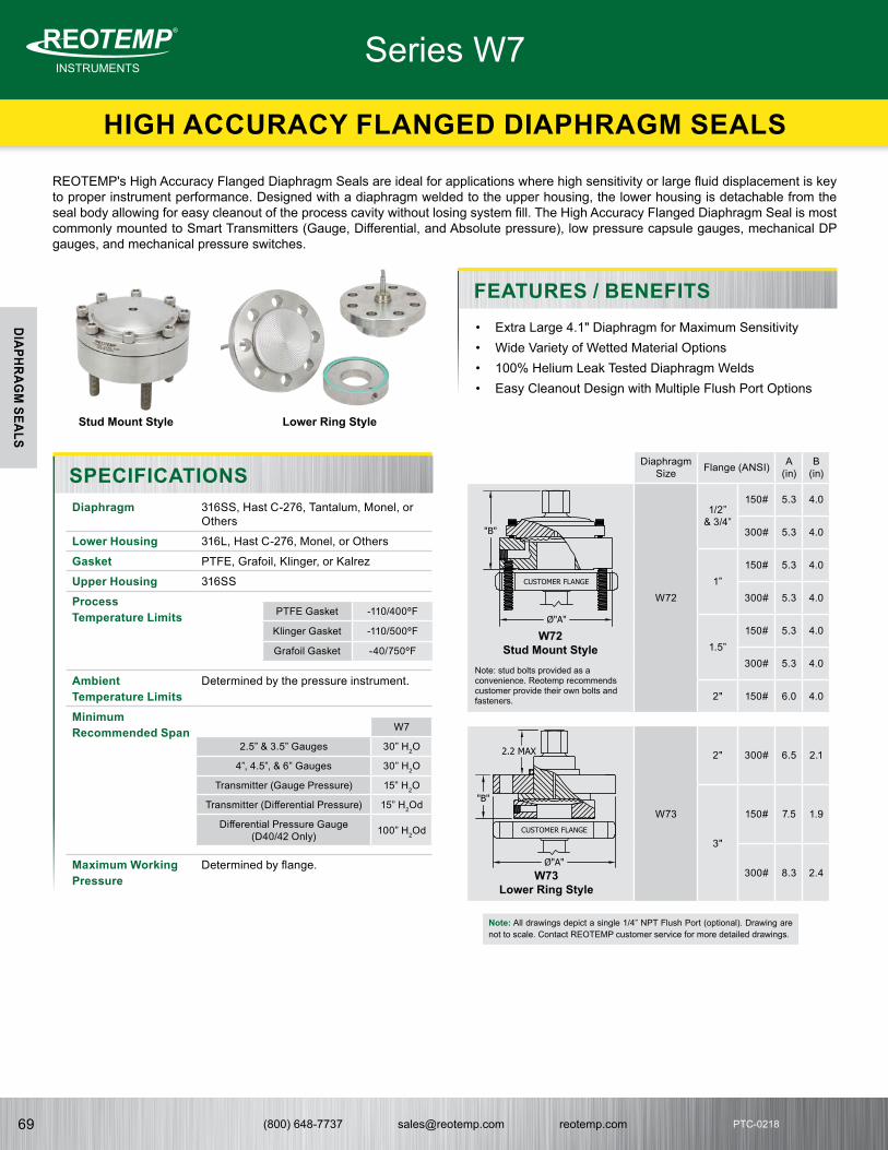
(800) 648-7737 [email protected] reotemp.com69
INSTRUMENTSMeasuring your world since 1965
®
PTC-0218
DIAPHRAGM
SEALS
Diaphragm Size Flange (ANSI) A
(in)B
(in)
W72
1/2” & 3/4”
150# 5.3 4.0
300# 5.3 4.0
1”150# 5.3 4.0
300# 5.3 4.0
1.5”150# 5.3 4.0
300# 5.3 4.0
2" 150# 6.0 4.0
W73
2" 300# 6.5 2.1
3"
150# 7.5 1.9
300# 8.3 2.4
HIGH ACCURACY FLANGED DIAPHRAGM SEALS
Series W7
• Extra Large 4.1" Diaphragm for Maximum Sensitivity• Wide Variety of Wetted Material Options• 100% Helium Leak Tested Diaphragm Welds• Easy Cleanout Design with Multiple Flush Port Options
REOTEMP's High Accuracy Flanged Diaphragm Seals are ideal for applications where high sensitivity or large fluid displacement is key to proper instrument performance. Designed with a diaphragm welded to the upper housing, the lower housing is detachable from the seal body allowing for easy cleanout of the process cavity without losing system fill. The High Accuracy Flanged Diaphragm Seal is most commonly mounted to Smart Transmitters (Gauge, Differential, and Absolute pressure), low pressure capsule gauges, mechanical DP gauges, and mechanical pressure switches.
W7
2.5” & 3.5” Gauges 30” H2O
4”, 4.5”, & 6” Gauges 30” H2O
Transmitter (Gauge Pressure) 15” H2O
Transmitter (Differential Pressure) 15” H2Od
Differential Pressure Gauge(D40/42 Only) 100” H2Od
PTFE Gasket -110/400ºF
Klinger Gasket -110/500ºF
Grafoil Gasket -40/750ºFW72
Stud Mount Style
W73Lower Ring Style
Stud Mount Style Lower Ring Style
SPECIFICATIONS
FEATURES / BENEFITS
Note: All drawings depict a single 1/4” NPT Flush Port (optional). Drawing are not to scale. Contact REOTEMP customer service for more detailed drawings.
Note: stud bolts provided as a convenience. Reotemp recommends customer provide their own bolts and fasteners.
Diaphragm 316SS, Hast C-276, Tantalum, Monel, or Others
Lower Housing 316L, Hast C-276, Monel, or Others
Gasket PTFE, Grafoil, Klinger, or Kalrez
Upper Housing 316SS
Process Temperature Limits
Ambient Temperature Limits
Determined by the pressure instrument.
Minimum Recommended Span
Maximum Working Pressure
Determined by flange.1234
ASS-W715-A
"B"
Ø"A"
GASKET
"C" NPTDIAPHRAGM
ASS-W716-A
"B"
Ø"A"
Ø"A"
"B"
ASS-W725-AASS-W726-A
Ø"A"
"B"
ASS-W735-A
Ø"A"
"B"
2.2 MAX
ASS-W736-A
Ø"A"
"B"
2.2 MAX
ASS-TF75-A3/4" NPT
DIAPHRAGM
2.0" MAX1.8"
ASS-TF10-A
1" NPTDIAPHRAGM
2.6"2.0" MAX
ASS-TF05-A1.0" MAX
1.1"
DIAPHRAGM
1/2" NPT
ASS-TF15-A2.3" MAX
2.6"
DIAPHRAGM
1-1/2" NPT
CUSTOMER FLANGE
CUSTOMER FLANGE
CUSTOMER FLANGE
CUSTOMER FLANGE
1234
ASS-W715-A
"B"
Ø"A"
GASKET
"C" NPTDIAPHRAGM
ASS-W716-A
"B"
Ø"A"
Ø"A"
"B"
ASS-W725-AASS-W726-A
Ø"A"
"B"
ASS-W735-A
Ø"A"
"B"
2.2 MAX
ASS-W736-A
Ø"A"
"B"
2.2 MAX
ASS-TF75-A3/4" NPT
DIAPHRAGM
2.0" MAX1.8"
ASS-TF10-A
1" NPTDIAPHRAGM
2.6"2.0" MAX
ASS-TF05-A1.0" MAX
1.1"
DIAPHRAGM
1/2" NPT
ASS-TF15-A2.3" MAX
2.6"
DIAPHRAGM
1-1/2" NPT
CUSTOMER FLANGE
CUSTOMER FLANGE
CUSTOMER FLANGE
CUSTOMER FLANGE

(800) 648-7737 [email protected] reotemp.com 70
INSTRUMENTSMeasuring your world since 1965
®
PTC-0218PTC-0218
DIAPHRAGM
SEALS
HIGH ACCURACY FLANGED DIAPHRAGM SEALS
Series W7
W7 6 2 R 2 1 S
S S DTD -AS -OX-K
2
FLUSH PORT
5 = No Flush Port6 = Single 1/4” NPT7 = Dual 1/4” NPTC = Single 1/2” NPT1
D = Dual 1/2” NPT1
11/2" NPT Flush may increase "B" dimension.
Note: Stainless steel plugs are furnished with flush ports.
INSTRUMENT CONNECTION
2 = 1/2” Female NPT
4 = 1/4” Female NPT
W = Low-Volume Connection for Smart Transmitters
SEALING FACE
R = Raised FaceJ = Ring Type JointF = Flat Face
PIPE SIZE
0 = 1/2” ANSIT = 3/4” ANSI1 = 1” ANSI H = 1 ½” ANSI2 = 2” ANSI3 = 3” ANSI4 = 4” ANSI
FLANGE RATING
1 = 150#3 = 300#6 = 600#9 = 900/1500#5 = 2500#7 = 900#2
8 = 1500#2
2For 3" pipe size and larger.
HOUSING
2 = Stud Mount Style
3 = Lower Ring Style
SEAL TYPE
W7 = 4.1” Diaphragm
DIAPHRAGM MATERIAL
S = 316LH = Hast C-276U = TantalumM = Monel
(A400)D = Alloy 20Y = InconelN = NickelJ = Titanium3
2 = Duplex 2205
3Only available with Titanium upper housing.
LOWER HOUSING
S = 316LH = Hast C-276M = Monel (A400)D = Alloy 20G = Hast B2 = Duplex 2205J = TitaniumF = 304LJ = Nickel
UPPER HOUSING
S = 316SS
GASKET
-K = Klinger C-4401-T = PTFE-G = Grafoil-Z = Kalrez
SYSTEM FILL FLUID
Common Fills-AS = Silicone DC200-AG = Glycerin USP-BH = Silicone DC704-C1 = Fomblin Y06 (inert)-C2 = Halocarbon 6.3
See 58 for Complete Fill Guide
-XX = No Fill Fluid
OPTIONS
-PP = Pulse Plus™ (Pulsation Protection)
-OX = Cleaned for Oxygen Service-AU = Gold-Plated Diaphragm-TC = Teflon-Coated Diaphragm-TS = SS Tag (1-10 Characters)-FW = Fill Port Welded Closed-NC = NACE Certification MRO-
175
See Page 83 for Additional Options
INSTRUMENT MOUNT
Direct MountDTD = Direct Mount, ThreadedDWD = Direct Mount, WeldedRTR = 6” Cooling TowerSTW = 3” Cooling StandoffRemote MountA?? = Armored Capillary, ThreadedB?? = Armored Capillary, WeldedP?? = PVC Coated Armor, ThreadedW?? = PVC Coated Armor, WeldedNote: ?? = Length in feet (e.g. 05 = 5 feet).
Tree MountTRE = Goal Post, Low PressureTRX = Goal Post, Heavy DutyTRM = Compact Tree Assembly
See Page 57 for Complete Mounting Guide
YYY = Dry Seal, No Instrument
HOW TO ORDER: Choose options to build a part number. For example: W7262R21SSS-KDTD-AS-OX
Seal Type
Pipe Size
W7
1/2” 2
3/4” 2
1” 2
1 ½” 2
2”150# 2
300# 3
3” 3
Housing Details
Wetted
Wetted
Wetted
See Page 55 for Smart Transmitter Attachment Codes
1
1
2
2
3
3
4
4
A A
B B
C C
D D

(800) 648-7737 [email protected] reotemp.com71
INSTRUMENTSMeasuring your world since 1965
®
PTC-0218
DIAPHRAGM
SEALS
FLANGED FLUSH FACE DIAPHRAGM SEALS
Series W9F
• One-piece Seal Design Bolts Directly to Process Flange• Center Instrument Exit• Commonly Supplied with Flush/Calibration Ring• Ideal for Gauge or Differential Pressure Transmitters
REOTEMP’s Flanged Flush-Face Diaphragm Seals are useful in applications where a continuous flow of process across the diaphragm is required to prevent solids buildup and a one-piece, all-welded construction is desired.
Weights and Dimensions:
Maximum Working Pressures at 100ºF: Determined by ANSI B16.5 flange ratings.
W9FFWetted Flange
W9FRIntegral Face Non-wetted Flange
1.4”
Threaded Instrument Connection
Low Volume/Capillary Connection
Flange Rating A B # of
BoltsWeight (Lbs.)
1 ½”
150#
5” .69” 4 4
2” 6” .75” 4 5
3” 7.5” .94” 4 9
4” 9” .94” 8 17
1 ½”300#
6.13” .81” 4 6
2” 6.5” .88” 8 8
3” 8.25” 1.13” 8 16
NOTE: Weights and dimensions are for raised face flanges only. Other flange sizes and sealing face info can be found in ANSI B16.5 standards.
SPECIFICATIONS
FEATURES / BENEFITS
Diaphragm Size
1.8" 2.2" 3.5" 4.1"
2.5” & 3.5” Gauges 30 psi 15 psi 10 psi 30" H2O
4”, 4.5”, & 6” Gauges N/A 60 psi 10 psi 30" H2O
Transmitter (Gauge Pressure) 10 psi 100” H2O 30” H2O 15" H2O
Transmitter (Differential Pressure) N/A 150” H2Od 30” H2Od 15" H2Od
Differential Pressure Gauge N/A N/A N/A 100" H2Od
Diaphragm Size
1.8" 2.2" 3.5" 4.1"
1-1/2" Flange STD N/A N/A N/A
2" Flange -D5 STD N/A N/A
3" Flange -D5 -D6 STD N/A
4" Flange -D5 -D6 STD -D9
Optional Diaphragm sizes are only available in W9FF, standard diaphragm sizes are the same for W9FF and W9FR.
Wetted Materials Flange: 316SS, 304SS, Monel, Alloy 20, or Hast C-276.Diaphragm: 316SS, Hast C-276, Tantalum, Monel, or others
Process Temperature Limits
-110° to 750°F
Ambient Temperature Limits
Determined by the pressure instrument.
Minimum Recommended Span
Available Diaphragm Sizes

(800) 648-7737 [email protected] reotemp.com 72
INSTRUMENTSMeasuring your world since 1965
®
PTC-0218PTC-0218
DIAPHRAGM
SEALS
FLANGED FLUSH FACE DIAPHRAGM SEALS
Series W9F
W9FF W R 2 1 S
-W10 -AS -TS // DXFR241S
HOW TO ORDER: Choose options to build a part number. For example: W9FFWR21S-W10-AS-TS // DXFR241S
SEAL TYPE
Selections for W9FF >W9FF = Flanged Flush Face (Wetted Flange)
Selections for W9FR >W9FR = Flanged Flush Face, Integral Face (Non- Wetted Flange)
INSTRUMENT CONNECTION
2 = 1/2” Female NPT4 = 1/4” Female NPTW = Low-Volume
Connection for Smart Transmitters
2 = 1/2” Female NPT4 = 1/4” Female NPTW = Low-Volume
Connection for Smart Transmitters
SEALING FACE
R = Raised-FaceJ = Ring-Type
JointF = Flat Face
R = Raised-FaceJ = Ring-Type
Joint
PIPE SIZE
H = 1-½” ANSI2 = 2” ANSI3 = 3” ANSI4 = 4” ANSI6 = 6” ANSI
H = 1-½” ANSI2 = 2” ANSI3 = 3” ANSI4 = 4” ANSI
PRESSURE RATING
1 = 150#3 = 300#6 = 600#9 = 900/1500#7 = 900#1
8 = 1500#1
1For 3" pipe size or larger.
1 = 150#3 = 300#6 = 600#9 = 900/1500#7 = 900#1
8 = 1500#1
1For 3" pipe size or larger.
DIAPHRAGM/FLANGE MATERIAL
S = 316L/316LM = Monel/Monel*F = 304/304L*H = Hast C-276/Hast
C-276*
*Non-standard configuration.
Wetted Insert & DiaphragmH = Hast C-276U = Tantalum2 = Duplex 2205J = TitaniumI = InconelZ = ZirconiumM = Monel A400
Note: Non-wetted 316SS flange.
INSTRUMENT MOUNT
Selections for Both W9FF & W9FR >-DTD = Direct Mount, Threaded-DWD = Direct Mount, Welded-RTR = 6” Cooling Tower-STW = 3” Cooling Tower-A?? = Armored Capillary, Threaded-B?? = Armored Capillary, Welded-P?? = PVC Coated Armor, Threaded-W?? = PVC Coated Armor, WeldedNote: ?? = Length in Feet (e.g. 05 = 5 feet)
See Page 57 for Complete Mounting Guide
-YYY = Dry Seal, No Instrument
SYSTEM FILL FLUID
Common Fills-AS = Silicone DC200-AG = Glycerin USP-BH = Silicone DC704-C1 = Fomblin Y06-C2 = Halocarbon 6.3
See 58 for Complete Fill Guide
-XX = No Fill Fluid
OPTIONS
-OX = Cleaned for Oxygen Service
-AU = Gold-Plated Diaphragm (20 Microns)
-NC = NACE Certification MRO-175
-TC = Teflon-Coated Diaphragm
-TS = SS Tag (9 Character Max.)
-D9 = 4.1" Diaphragm (W9FF 4" Only)
-D6 = 2.2" Diaphragm (Optional on W9FF 3" and 4")
FLUSH/CALIBRATION RINGS (OPTIONAL)
DXFR241S = 2” Pipe, Single 1/4” Port, 316SSDXFR242S = 2” Pipe, Dual 1/4” Port, 316SSDXFR221S = 2” Pipe, Single 1/2” Port, 316SSDXFR222S = 2” Pipe, Dual 1/2” Port, 316SSDXFR341S = 3” Pipe, Single 1/4” Port, 316SSDXFR342S = 3” Pipe, Dual 1/4” Port, 316SSDXFR321S = 3” Pipe, Single 1/2” Port, 316SSDXFR322S = 3” Pipe, Dual 1/2” Port, 316SS
See Page 81 for Complete Offering
W9FF 1-Piece Flange & Diaphragm are Same Material
Diaphragm Foil
Diaphragm Surface Wetted Surface
Wetted
Wetted
See Page 55 for Smart Transmitter Attachment Codes
1
1
2
2
3
3
4
4
A A
B B
C C
D D
W9FR 2-Piece 316 Flange & Wetted Insert, Material as Selected

(800) 648-7737 [email protected] reotemp.com73
INSTRUMENTSMeasuring your world since 1965
®
PTC-0218
DIAPHRAGM
SEALS
EXTENDED DIAPHRAGM SEAL
Series W9XT
The Extended Diaphragm Seal is ideal for highly viscous and dry powder applications. Its unique design eliminates dead space in piping. It is often used for flush mounting in thick-walled vessels and is available in standard and custom lengths.
W9XTX
SPECIFICATIONS
MODEL
W9XT = Flanged Extended Diaphragm
INSTRUMENT CONNECTION
W = Low-Volume Connection for Smart Transmitters
2 = 1/2” NPT Female4 = 1/4” NPT Female
SEALING FACE
R = Raised FaceJ = Ring Type
Joint
DIAPHRAGM MATERIAL
S = 316LSSH = Hastelloy C-276
PIPE SIZE
H = 1.5” Pipe2 = 2” Pipe3 = 3” Pipe4 = 4” Pipe6 = 6” Pipe
FLANGE RATING
1 = 150# ANSI3 = 300# ANSI6 = 600# ANSI
EXTENSION MATERIAL
S = 316LSSH = Hastelloy C-276
FLANGE/SEALING FACE MATERIAL
S = 316LSSH = Hast. C-276
EXTENSION LENGTH (X)
020 = 2”040 = 4”060 = 6”??? = Enter Custom
Length in Inches
Note: ??? = Length in inches (e.g. 020 = 2 inches).
MOUNTING
-DWD = Direct Mount, All Welded-RTR = 6” Cooling Tower, Welded-B?? = SS Armored Capillary, Welded-W?? = PVC Coated SS Armored Capillary,
WeldedNote: ?? = Length in feet (e.g. 05 = 5 feet)
See Page 57 for Complete Mounting Guide
FILL FLUID
-AS = Silicone DC200-AG = Glycerin USP-BH = Silicone DC704-C1 = Fomblin Y06 (inert)-C2 = Halocarbon 6.3
See Page 58 for Complete Fill Guide
OPTIONS
-DG = Degreased and Bagged-AU = Gold Plated Diaphragm (20
Microns Thick)-TS = SS Tag (1-10 Characters)
See Page 55 for Smart Transmitter Attachment Codes
HOW TO ORDER: Choose options to build a part number. For example: W9XTWR31SSS020-W10-AS-DG
W9XT R 3 1 S S
020 -AS -DG-W10
W
S
2” 3” 4”
Transmitter (Gauge Pressure) 200 ”H2O 100 ”H2O 30 ”H2O
Transmitter (Differential Pressure) 200 ”H2Od 150 ”H2Od 30 ”H2Od
W9XT
Wetted Wetted
Wetted
Dimensions:Flange Rating A B E*
1.5” 150# 5” 0.70” 1.40”
2”150# 6" 0.75" 1.90"
300# 6.5" 0.88" 1.90"
3”150# 7.5" 0.94" 2.80"
300# 8.25" 1.13" 2.80"
4”150# 9" 0.94" 3.70"
300# 10" 1.19" 3.70"
6" 150# 11" 0.94" 5.7"
*Extension diameter meant to fit SCH80 Nozzle. Custom extension diameters available.
NOTE: Dimensions are for raised face flanges only. Other flange sizes and sealing face info can be found in ANSI B16.5 standards.
Wetted Materials 316L or Hast C-276
Process Temperature Limits
-110°F to 750°F
Ambient Temperature Limits
Determined by the pressure instrument.
Minimum Recommended Span

(800) 648-7737 [email protected] reotemp.com 74
INSTRUMENTSMeasuring your world since 1965
®
PTC-0218PTC-0218
DIAPHRAGM
SEALS
FLUSH PANCAKE (WAFER) DIAPHRAGM SEAL
Series W9FP
The Flush Pancake (Wafer) Diaphragm Seal is a flange type diaphragm seal with no bolt holes. It mounts between an open process flange and cover flange. Instruments are connected via side capillary connection and it is an ideal seal for transmitters or dP transmitters.
W9FP
W9FP with Backing Flange
W 9” Nom.
5/16” - 24 MountingStud for Backing Flange
Rigid Handle
Raised Face
Capillary
SPECIFICATIONS
HOW TO ORDER: Choose options to build a part number. For example: W9FPWR2SF1-W10-AS-DG // DXFR242S
W9FP R 2 S F 1
-AS -DG
W
-W10
OPTIONS
-DG = Degreased and Bagged-OX = Cleaned for Oxygen Service (Shipped in
Sealed Bag)-AU = Gold Plated Diaphragm (20 microns thick)-TS = SS Tag (1-10 Characters)
See Page 55 for Smart Transmitter Attachment Codes
MOUNTING
-B?? = SS Armored Capillary, Welded
-W?? = PVC Coated SS Armored Capillary, Welded
Note: ?? = Length in feet (e.g. 05 = 5 feet)
FILL FLUID
-AS = Silicone DC200-AG = Glycerin USP-BH = Silicone DC704-C1 = Fomblin Y06 (inert)-C2 = Halocarbon 6.3
See Page 58 for Complete Fill Guide
MODEL
W9FP = Flanged Pancake
INSTRUMENT CONNECTION
W = Low-Volume Connection for Smart Transmitters
SEALING FACE
R = Raised Face
DIAPHRAGM/WETTED SURFACE MATERIAL
S = 316LSS*H = Hastelloy C-276
*Non-wetted body is 316L
PIPE SIZE
2 = 2” Pipe3 = 3” Pipe4 = 4” Pipe6 = 6” Pipe
FLANGE RATING
X = No Backing Flange1 = 150#3 = 300#6 = 600#5 = 2500#9 = 900#/1500#7 = 900#1
8 = 1500#1
1For 3" Pipe Size or Larger
BACKING FLANGE MATERIAL
X = No Backing FlangeS = 316LSSF = 304SSC = Carbon Steel
2” 3” & 4”
Transmitter (Gauge Pressure) 100” H2O 30” H2O
Transmitter (Differential Pressure) 150” H2Od 30” H2Od
Wafer Size 2" 3" 4"
W 3.6" 5.0" 6.2"
// DXFR242S
FLUSH/CALIBRATION RINGS (OPTIONAL)
DXFR242S = 2” Pipe, Dual 1/4” Port, 316SS
DXFR322S = 3” Pipe, Dual 1/2” Port, 316SS
See Page 81 for a Complete List
Wetted
Wetted
W9FP
Wetted Materials 316L or Hast C-276
Process Temperature Limits
-110°F to 750°F
Ambient Temperature Limits
Determined by the pressure instrument.
Minimum Recommended Span

(800) 648-7737 [email protected] reotemp.com75
INSTRUMENTSMeasuring your world since 1965
®
PTC-0218
DIAPHRAGM
SEALS
THREADED FLUSH FACE DIAPHRAGM SEALS
Series DSTF
REOTEMP’s Threaded Flush Face Seals are ideal for high and medium pressure applications where process media clogging is a concern. The diaphragm is welded onto the end of the threads allowing for continuous flow of process media across the diaphragm and preventing any build-up of solids. Selection of process connection will greatly impact accuracy and temperature sensitivity.
DSTF05
DSTF15
DSTF10
DSTF75
Male Process Thread NPT 1/2" 3/4" 1" 1.5"/2"
2.5” & 3.5” Gauges 60 psi 30 psi 15 psi 15 psi
4”, 4.5”, & 6” Gauges n/a n/a 100 psi 30 psi
Transmitter (Gauge Pressure) 60 psi* 15 psi* 10 psi* 5 psi
Transmitter (Differential Pressure) n/a n/a n/a n/a
DSTF
HOW TO ORDER
SPECIFICATIONS
HOW TO ORDER: Choose options to build a part number. For example: DSTF75SS4-DTD-AS-OX
DSTF SS 4 -DTD -AS -OX75
MODEL
DSTF = Threaded Flush Face Diaphragm Seal
PROCESS CONNECTION
05 = 1/2” Male NPT75 = 3/4” Male NPT10 = 1” Male NPT15 = 1-1/2” Male
NPT20 = 2” Male NPTG1 = 1” BSPP (G1)GH = 1.5” BSPPG2 = 2" BSPP
DIAPHRAGM AND BODY MATERIAL
SS = 316LSSHC = Hast. C-276
INSTRUMENT CONNECTION
4 = 1/4” NPT2 = 1/2” NPT1
1Not Available with 1/2" NPT Process Connection
MOUNTING
-DTD = Direct Mount, Threaded-DWD = Direct Mount, Welded-STW = 3” Cooling Standoff-RTR = 6” Cooling Tower,
Welded
See Page 57 for Complete Mounting Guide
-YYY = No Instrument Mount, Dry Seal Only
FILL FLUID
-AS = Silicone DC200
-AG = Glycerin USP
-C2 = Halocarbon 6.3
See Page 58 for Complete Fill Guide
-XX = No Seal Fill, Dry Seal Only
OPTIONS
-OX = Cleaned for Oxygen Service (Shipped in Sealed Bag)
-AU = Gold Plated Diaphragm (20 Microns Thick)
-TS = SS Tag (1-10 Characters)
Wetted
Process Connection 1/2" 3/4" 1" 1.5"/2"
Limit 0/150°F 20/200°F -40/400°F -40/600°F
Wetted Materials Body: 316SS, Hast-CDiaphragm: 316SS, Hast-C
Process Temperature Limits
NOTE: Always use largest thread possible for smaller temperature effect.
Ambient Temperature Limits
Determined by the pressure instrument.
Minimum Recommended Span
*Not Recommended for Critical Transmitter Applications.
Maximum Working Pressure
Determined by the seal threads.
1234
ASS-W715-A
"B"
Ø"A"
GASKET
"C" NPTDIAPHRAGM
ASS-W716-A
"B"
Ø"A"
Ø"A"
"B"
ASS-W725-AASS-W726-A
Ø"A"
"B"
ASS-W735-A
Ø"A"
"B"
2.2 MAX
ASS-W736-A
Ø"A"
"B"
2.2 MAX
ASS-TF75-A3/4" NPT
DIAPHRAGM
2.0" MAX1.8"
ASS-TF10-A
1" NPTDIAPHRAGM
2.6"2.0" MAX
ASS-TF05-A1.0" MAX
1.1"
DIAPHRAGM
1/2" NPT
ASS-TF15-A2.3" MAX
2.6"
DIAPHRAGM
1-1/2" NPT
CUSTOMER FLANGE
CUSTOMER FLANGE
CUSTOMER FLANGE
CUSTOMER FLANGE

(800) 648-7737 [email protected] reotemp.com 76
INSTRUMENTSMeasuring your world since 1965
®
PTC-0218PTC-0218
DIAPHRAGM
SEALS
ISOLATION RING FLOW THRU SEAL
Series OR
The REOTEMP Isolation Ring Flow Thru Seal boasts an In-Line Flow-Thru design ideal for waste water, slurries, or abrasives. Mounted between pipe flanges or threaded in-line, it has a tough but sensitive elastomer lining. One unique feature of this seal is the ability to mount multiple instruments on one seal.
Wafer ThreadedORR
Sleeve Material Limit
Buna-N 225ºF
Fluorocarbon 400ºF
PTFE 350ºF
Silicone 450ºF
EPDM 300ºF
Natural Rubber 212ºF
SPECIFICATIONS
HOW TO ORDERHOW TO ORDER: Choose options to build a part number. For example: ORTCC2020-TRE-AG-TS
ORT C 2 020 -TRE -TSC
MODEL
ORR = Ring Seal, Flanged Wafer
ORT = Threaded Spool
ORB= Ring Seal, Bolt-thru
BODY
C = Carbon SteelS = 316 SS
END FLANGE
C = Carbon Steel
S = 316 SS
DIAPHRAGM/ SLEEVE
1 = Buna2 = Fluorocarbon3 = PTFE4 = EPDM5 = Silicone*
*ORT Only
PIPE SIZE
020 = 2” Flanged040 = 4” Flanged060 = 6” Flanged080 = 8” Flanged010 = 1” NPT
Threaded*015 = 1.5” NPT
Threaded*
Other sizes available.
*ORT Only
MOUNTING
-DTD = Direct Mount, Threaded
-TRE = Goal Post, Low Pressure
-TRX = Goal Post, Heavy Duty
See Page 57 for Complete Mounting Guide
-YYY = No Instrument Mount, Dry Seal Only
FILL FLUID
-AS = Silicone DC200-AG = Glycerin USP-BP = Propylene
Glycol
See Page 58 for Complete Fill Guide
-XX = No Fill Fluid
OPTIONS
-IR = Instrument Removal Device
-TS = SS Tag (1-10 Characters)
-RV = Red Valve Brand
-AG
Type Nominal Pipe Size A B
Approx. Weight
(lbs)
Iso-Ring(Wafer)
2" 4" 2” 4
4" 6.75" 1.5" 8
6" 8.63" 1.5" 10
8" 10.88” 1.5" 15
Iso-Spool (Threaded)
1” NPT 3” 3.25” 10
1-1/2” NPT 3.5” 3.25” 12
Red Valve brand is available if the application requires. Choose -RV as option code. Red Valve dimensions may differ from above.
Wetted
Wetted
Materials Body: Carbon Steel, 316SS
Wetted Materials End Flange: Carbon Steel, 316SS. Diaphragm/Sleeve: Buna-N, PTFE EPDM, Natural Rubber and more.
Process Temperature Limits
Ambient Temperature Limits
Determined by the pressure instrument.
1
1
2
2
3
3
4
4
A A
B B
C C
D D
B
B
A
A
1
1
2
2
3
3
4
4
A A
B B
C C
D D
B
B
A
A
1
1
2
2
3
3
4
4
A A
B B
C C
D D
B
B
A
A
1
1
2
2
3
3
4
4
A A
B B
C C
D D
B
B
A
A

(800) 648-7737 [email protected] reotemp.com77
INSTRUMENTSMeasuring your world since 1965
®
PTC-0218
DIAPHRAGM
SEALS
WELDED MINI-SEAL
Series MS
REOTEMP Welded Mini Seals are ideal for applications where a gauge or general purpose transmitter cannot be installed directly into the process media. REOTEMP mini seals are a one-piece, all-welded construction that offer a durable, economical choice for protecting a pressure instrument from corrosion, clogging, or high process temperatures.
MS4G MS8QMS6G
MS4G
MS8Q
MS6G
SPECIFICATIONS
MS4 MS6 MS8
2.5” & 3.5” Gauges 30 psi 15 psi 15 psi
4”, 4.5”, & 6” Gauges n/a 60 psi 30 psi
Transmitter (Gauge Pressure) 15 psi 10 psi 150” WC
Transmitter (Differential Pressure) n/a n/a 300” WC
316SS Hast-C Monel
MS4 2,000 psi 1,000 psi 2,000 psi
MS6 1,000 psi N/A N/A
MS8 (1/4 or 1/2” connectors) 5,000 psi 2,000 psi 2,000 psi
MS8 (3/4” or 1") 2,000 psi N/A N/A
• Economical Choice for Protecting a Pressure Instrument from Severe Process Media
• All-welded Design Reduces Fugitive Emission Leaks• Available with PulsePlus™ Pulsation Dampening• Tamper Resistant
FEATURES / BENEFITS
Depicted with female Process Connection. Height will change with male fitting.
Depicted with female Process Connection. Height will change with male fitting.
Depicted with 1/2” Male Connection. Height will change with female fitting.
Materials Upper Housing: 316SS.Diaphragm: 316SS Hast C-276, Monel.Lower Housing: 316SS, Hast C-276, Monel
Process Temperature Limits
Ambient Temperature Limits
Determined by the pressure instrument.
Minimum Recommended Pressure Ranges
Maximum Working Pressure at 100°F
Weight
MS4 -40°F/300°F
MS6 -40°F/400°F
MS8 -110°F/750°F
MS4 .2 lbs
MS6 .4 lbs
MS8 .8 lbs

(800) 648-7737 [email protected] reotemp.com 78
INSTRUMENTSMeasuring your world since 1965
®
PTC-0218PTC-0218
DIAPHRAGM
SEALS
WELDED MINI-SEAL
Series MS
MS4G F4 X S
-DTD -AS -PP
2
HOW TO ORDER: Choose options to build a part number. For example: MS4G2F4XS-DTD-AS-PP
SEAL TYPE
MS4G = Compact Mini SealMS6G = Standard Mini SealMS8Q = Process Seal
Note: If mounting an MS8 to a REOTEMP gauge, use part builder on Page 10.
INSTRUMENT CONNECTION
4 = 1/4” Female NPT 2 = 1/2” Female NPT
(MS6 Only)W = Welded Connection
(MS8 Only)
PROCESS CONNECTION
F4 = 1/4” FNPTF2 = 1/2” FNPTM4 = 1/4” MNPTM2 = 1/2” MNPTM3 = 3/4” MNPT (MS8 only)M1 = 1” MNPT (MS8 only)
FLUSH PORT
X = NoneF = 1/4” Female
NPT
MATERIAL
S = 316LSSH = Hast C-276*M = Monel A400*
*See Maximum Working Pressure Table on Page 77 for Material Availability by Seal Type
INSTRUMENT MOUNT
-DTD = Direct Mount, Threaded-DWD = Direct Mount, Welded-RTR = 6” Cooling Tower-STW = 3” Cooling Tower-A?? = Armored Capillary, Threaded-B?? = Armored Capillary, Welded-W?? = PVC Coated Armor, Welded -P?? = PVC Coated Armor, Threaded
Note: ?? = Length in feet (e.g. 05 = 5 feet)
See Page 57 for Complete Mounting Guide
-YYY = Dry Seal, No Instrument
SYSTEM FILL FLUID
-AS = Silicone DC200-AG = Glycerin USP-BH = Silicone DC704-C1 = Fomblin Y06 (inert)-C2 = Halocarbon 6.3
See Page 58 for Complete Fill Guide
-XX = No Fill Fluid
OPTIONS
-PP = Pulse Plus™ (Pulsation Protection)
-TS = SS Tag (1-10 Character)-FW = Fill Port Welded Closed-PM = Positive Material
Identification Certification
Wetted
Using a REOTEMP Gauge? If mounting an MS8 to a REOTEMP gauge, use the part builder on Page 10 or the online configurator at reotemp.com/configurators

(800) 648-7737 [email protected] reotemp.com79
INSTRUMENTSMeasuring your world since 1965
®
PTC-0218
DIAPHRAGM
SEALS
Series DSTC
REOTEMP’s Sanitary Tri-Clamp® Diaphragm Seals are ideal for applications in the food and beverage, dairy, and pharmaceutical industries or wherever Tri-Clamp connections are used. Reotemp will mount and fill a variety of instruments to Tri-Clamp seals including Digital Pressure Gauges, Transmitters, and Switches. All Sanitary Diaphragm Seal Assemblies manufactured by Reotemp are 3-A Certified.
DSTC15
Certified
SPECIFICATIONS
HOW TO ORDERHOW TO ORDER: Choose options to build a part number. For example: DSTC20SS4-DWD-BN-OX
DSTC SS 4 -DWD -OX20 -BN
TRI-CLAMP® SIZE
75 = 3/4” (Also Fits a 1/2” Clamp)*
15 = 1 1/2” (Also Fits a 1” Clamp)
20 = 2”25 = 2.5”30 = 3”40 = 4”
*Not available in "I" Line.
MATERIAL
SS = 316L SSHC = Hast. C-276
MODEL
DSTC = Diaphragm Seal Sanitary Tri-Clamp
DSCI = Diaphragm Seal Sanitary "I"-Line Cherry Burrell
INSTRUMENT CONNECTION
4 = 1/4” NPTW = Low-Volume
MOUNTING
-DWD = Direct Mount, All Welded-DTD = Direct Mount, Threaded (not
standard for sanitary applica-tions)
-RTR = 6” Cooling Tower, Welded-STW = 3” Cooling Standoff-WXX = PVC Coated SS Armored
Capillary, Welded to Seal, XX = length in feet
See Page 57 for Complete Mounting Guide
-YYY = No Instrument Mount, Dry Seal Only
FILL FLUID
-AG = Glycerin-BN = NEOBEE M20-AS = Silicone
DC200-BS = Food-Grade
Silicone
See Page 58 for Complete Fill Guide
-XX = No Fill Fluid
OPTIONS
-EP = Electropolished Diaphragm
-OX = Cleaned for Oxygen or Chlorine Service (shipped in sealed bag)
-TS = SS Tag (1-10 Characters)
C D Tri-Clamp End Cap
H
H
C D
Type BType A
Process Connection 3/4” 1.5” 2” 2.5” & 3”
Temperature Limit 0/150°F -40/250°F -40/400°F -40/750°F
Type A Type B
Process Connection 3/4"* 1.5" 2" 2.5" 3" 4'
Outer Diameter (C) 1" 2" 2.5" 3.1" 3.6" 4.7"
Diaphragm (D) .65" 1.4" 1.9" 2.2" 2.5" 3.6"
Height (H) 1' 1.3" 1.3" 1.3" 1.3" 1.6"
*DSTC75 ONLYNote: Height is subject to change based on the adapter required to fit instrument to seal.
Tri-Clamp® is a registered trademark of Alpha Laval Inc.
SANITARY TRI-CLAMP® DIAPHRAGM SEAL
Materials Body: 316LDiaphragm: 316L
Process Temperature Limits
Ambient Temperature Limits
Determined by the pressure instrument.
Wetted Surface Finish
18-24 Ra

(800) 648-7737 [email protected] reotemp.com 80
INSTRUMENTSMeasuring your world since 1965
®
PTC-0218PTC-0218
DIAPHRAGM
SEALS
Diaphragm Seals
REOTEMP’s Sanitary Tank Spud Diaphragm Seals are ideal for applications in the food and beverage, dairy, and pharmaceutical industries. Reotemp will mount and fill a variety of instruments to Tank Spud Diaphragm Seals including Digital Pressure Gauges, Transmitters, and Switches. All Sanitary Diaphragm Seal Assemblies manufactured by REOTEMP are 3-A Certified.
DSTP40
Certified
SPECIFICATIONS
HOW TO ORDERHOW TO ORDER: Choose options to build a part number. For example: DSTP40SS46X-DWD-BN-OX
SS 4 -DWD -OX6 -BN
EXTENSION LENGTH "H"
2 = 2" 6 = 6"
DIAPHRAGM & EXTENSION
SS = 316L SSHC = Hastelloy
C-276
INSTRUMENT CONNECTION
W = Low-Volume Connection for Smart Transmitters
2 = 1/2" NPT4 = 1/4" NPT
MOUNTING
-DWD = Direct Mount, All Welded-DTD = Direct Mount, Threaded
(not standard for sanitary applications)
-RTR = 6” Cooling Tower, Welded-STW = 3” Cooling Standoff-WXX = PVC Coated SS
Armored Capillary, Welded to Seal,
XX = length in feet
See Page 57 for Complete Mounting Guide
-YYY = No Instrument Mount, Dry Seal Only
FILL FLUID
-BN = NEOBEE M20
-AG = Glycerin-AS = Silicone
DC200
See Page 58 for Complete Fill Guide
-XX = No Fill Fluid
OPTIONS
-EP = Electropolished Diaphragm
-OX = Cleaned for Oxygen or Chlorine Service (shipped in sealed bag)
-TS = SS Tag (1-10 Characters)
-5T = Clamp Fixture (5" Tri-clamp)
SizeExtension
Length "H"
2" 2.11"
6" 6.11"
Tri-Clamp® is a registered trademark of Alpha Laval Inc.
SANITARY TANK SPUD DIAPHRAGM SEAL
TANK SPUD TYPE L990.SD
3.63
4.00
5.22.24
"H"
DSTP40
MODEL
DSTP40 = Sanitary Tank Spud Diaphragm Seal
Materials Body: 316LDiaphragm: 316LO-Ring: EPDM (FDA Approved)
Process Temperature Limits
-40 to 250°F
Ambient Temperature Limits
Determined by the pressure instrument.
Wetted Surface Finish
18-24 Ra
Max Working Pressure
600 psig (Clamp Rating)
X
WELD SPUD FIXTURE
X = Not Included
W = Weld Spud Included
Wetted
Weld Spud (Optional)
All dimensions are in inches.
0.50“H”
5.98
5.223.69
DSTP40
Weld Spud (Optional)
All dimensions are in inches.
All dimensions are in inches.

(800) 648-7737 [email protected] reotemp.com81
INSTRUMENTSMeasuring your world since 1965
®
PTC-0218
DIAPHRAGM
SEALS
Diaphragm Seals
DIAPHRAGM SEAL ACCESSORIES
HOW TO ORDERHOW TO ORDER: Choose options to build a part number. For example: DXC4M4M10A-TS
DXC 4M 10 A4M -TS
INSTRUMENT CONNECTION
4M = 1/4" Male NPT
4F = 1/4" Female NPT
2M = 1/2" Male NPT
2F = 1/2" Female NPT
PROCESS CONNECTION
4M = 1/4" Male NPT
4F = 1/4" Female NPT
2M = 1/2" Male NPT
2F = 1/2" Female NPT
MODEL
DXC = Capillary
LENGTH IN FEET
05 = 5 ft.
10 = 10 ft.
20 = 20 ft.
?? = Specify, Length in feet
PROTECTION
A = Stainless Steel ArmorP = PVC Coated Stainless Steel ArmorB = Bare Capillary Tubing (Rare)
OPTIONS
-3M = 3mm ID (10 ft. Max)-TS = Stainless Steel Tag
(1-10 Characters)
HOW TO ORDERHOW TO ORDER: Choose options to build a part number. For example: DXFR322S-PM
DXFR 2 2 S3 -PM
PIPE SIZE
H = 1-1/2" ANSI2 = 2" ANSI3 = 3" ANSI4 = 4" ANSI
PORT SIZE
4 = 1/4" NPT2 = 1/2" NPT
MODEL
DXFR = Flush Ring
NUMBER OF PORTS
1 = One Port2 = Two Ports
(180° Opposed)
4 = Four Ports (90° Apart)
MATERIAL
S = 316SSH = Hast-C276M = MonelJ = Titanium2 = Duplex 2205D = Alloy 20
OPTIONS
-MR = Mill Certification-PM = Positive Material Identification
Certification-GS = 1/4" NPT SS Plug-G2 = 1/2" NPT SS Plug
DRY CAPILLARY
FLUSH RINGS
• Used When Pressure Instrument Needs to be Removed from Direct Contact of Installation Point
• All-welded 316SS Construction• Available up to 100 ft. in Length (Max 40 ft. in diaphragm seal assembly)• Max Working Pressure of 10,000 psig• 2mm ID Standard• Note: if capillary is part of a filled diaphragm seal system use 3 digit mounting
code per page 57 (Example: "A25" = 25' of armored capillary, threaded to seal)
• Used to Flush Process Fluid or Provide Access for Field Calibrations• Machined from Solid Bar Stock• Pressure Ratings Up to ANSI Class 2500• For Use with W9FF and W9FR Diaphragm Seals (Raised Face)

(800) 648-7737 [email protected] reotemp.com 82
INSTRUMENTSMeasuring your world since 1965
®
PTC-0218PTC-0218
DIAPHRAGM
SEALS
ü Check Stockü Configure Part #
ü Get Priceü Download PDF Data SheetsVisit reotemp.com
Diaphragm Seals
OTHER DIAPHRAGM SEAL TYPES
SADDLE WELD
PULP/PAPER
WEDGE TYPE
THREADED FLOW THRU
REOTEMP provides many special use and custom diaphragm seals. Consult customer service for specific application assistance.
• Remote Seal Assembly Repair
• Hydrostatic Testing
• Positive Material Identification
• Custom Diaphragm Seal Design
OTHER SERVICES
FLANGED FLOW THRU

(800) 648-7737 [email protected] reotemp.com83
INSTRUMENTSMeasuring your world since 1965
®
PTC-0218
DIAPHRAGM
SEALS
ü Check Stockü Configure Part #
ü Get Priceü Download PDF Data SheetsVisit reotemp.com
Diaphragm Seals
DIAPHRAGM SEAL OPTIONS
MS4MS6MS8
W5W6W7
T5 T6 V5
W9FFW9FR W9XT W9FP DSTC75
DSTC15 AND
LARGERDSTF05
DSTF75 AND
LARGEROR DXFR
PULSATION PROTECTION (ONLY AVAILABLE WITH REOTEMP PRESSURE GAUGE MOUNTED TO SEAL)
-PP Pulse Plus™ ü ü ü ü ü N/A N/A ü N/A ü ü N/A
DIAPHRAGM COATING
-AU Gold Plated Diaphragm N/A ü N/A ü ü ü ü ü ü ü N/A N/A
-TC Teflon Coated Diaphragm PTFE N/A ü N/A ü ü ü N/A ü N/A ü N/A N/A
-EP Electropolished Diaphragm N/A N/A N/A N/A N/A N/A ü ü ü ü N/A N/A
FILL
-FW Fill Port Welded Closed STD1 ü ü ü ü ü ü ü ü ü N/A N/A
-VF Fill for Vacuum Service N/A ü N/A ü ü ü N/A ü N/A ü N/A N/A
CLEANING AND FINISH
-DG Degreased, Shipped in Sealed Bag ü ü ü ü ü ü ü ü ü ü N/A ü
-OX Cleaned for Oxygen Service per ASME B40.1 ü ü N/A ü ü ü ü ü ü ü N/A ü
-OY Cleaned for Oxygen Service per MIL-STD-1330D ü ü N/A ü ü ü ü ü ü ü N/A ü
PLUG FOR FLUSH PORT
-GS 1/4” SS Plug Installed STD STD STD N/A N/A N/A N/A N/A N/A N/A N/A ü
-JS 1/2” SS Plug Installed N/A STD STD N/A N/A N/A N/A N/A N/A N/A N/A ü
-GH 1/4” Hast C Plug Installed ü ü ü N/A N/A N/A N/A N/A N/A N/A N/A ü
-JH 1/2” Hast C Plug Installed N/A ü ü N/A N/A N/A N/A N/A N/A N/A N/A ü
-GM 1/4” Monel Plug Installed N/A ü ü N/A N/A N/A N/A N/A N/A N/A N/A ü
-JM 1/2” Monel Plug Installed N/A ü ü N/A N/A N/A N/A N/A N/A N/A N/A ü
TAG OPTION
-TS Stainless Steel Tag (1-10 Characters) ü
-TM Stainless Steel Tag (11-80 Characters) ü
-TP Paper Tag ü
CERTIFICATION OPTIONS
-NC Certificate of NACE Compliance ü ü N/A ü ü ü N/A N/A ü ü N/A ü
-CM General Material Conformance ü ü ü ü ü ü ü ü ü ü ü ü
-MR MTR - Mill Test Report Certificate ü ü ü ü ü ü ü ü ü ü N/A ü
-PM PMI - Positive Material IdentificationCertificate ü ü ü ü ü ü ü ü ü ü N/A ü
-HT Hydrostatic Test per ASME B31.3 ü ü ü ü ü ü ü ü ü ü N/A N/A
-HL Helium Leak Test Certificate ü ü N/A ü ü ü ü ü ü ü N/A N/A
ü Indicates that the option is available
N/A Indicates the option is not available
1 Standard on MS8, available on MS4 & MS6.

(800) 648-7737 [email protected] reotemp.com 84
INSTRUMENTSMeasuring your world since 1965
®
PTC-0218PTC-0218
DIAPHRAGM
SEALS
ü Check Stockü Configure Part #
ü Get Priceü Download PDF Data SheetsVisit reotemp.com
Diaphragm Seals
DIAPHRAGM SEAL CONFIGURATOR
Try the new and easy-to-use Diaphragm Seal Configurator!
Visit reotemp.com/sealsand click the "Configure Now" button.
Select the mounting style. Select the seal type and follow our easy guided steps.
Select the instrument.
Part Number and Description of Assembly with Price
Engineering Drawing of Assembly
Easily Save your Quote and Put in a Purchase Request
ü
ü
ü

(800) 648-7737 [email protected] reotemp.com85
INSTRUMENTSMeasuring your world since 1965
®
PTC-0218
VALVES
Design: REOTEMP offers a full line of USA made instrument valves and manifolds. Whether your need is to safely remove instrumentation, pressure check or calibrate your process, test differential gauges/transmitters, or throttle flow in the system Reotemp has a valve to suit your application.
Quality: REOTEMP is a globally recognized ISO 9001:2008 manufacturer of pressure instrumentation. All instrument valves conform to MSS SP-99 standards, and all valves with packing conform to MSS SP-132 packing standards. All valves and manifolds are helium leak checked to 1 x 10⁻⁴ ml/s for ultimate performance. REOTEMP warrants all US made valves against defective workmanship or materials under normal use and service for three years following the date of shipment.
Additional Testing Services: Other in-house services include Mill Test Reports (MTRs), Positive Material Identification (PMI), Hydrostatic Testing, and Oxygen Cleaning (O2).
Configurations: Standard body materials include 316SS and zinc-plated carbon steel. Other non-standard materials are available upon request and may require a custom design and build. Various connections sizes are available from 1/8” – 2” NPT on most needle valve configurations. Gauge valves are available with connections from ¼” – ¾” NPT.
Instrument/Valve Mounting Options: REOTEMP offers in house mounting services by pre-installing pressure instrumentation on valve assemblies prior to shipping to allow for quick and easy installation. REOTEMP mounting services are available when mounting your REOTEMP pressure instrument to a REOTEMP gauge valve, or when mounting a REOTEMP differential pressure gauge on a 3 or 5 valve manifold. Select from a variety of options and orientations.
INSTRUMENTSMeasuring your world since 1965
®
INSTRUMENT VALVES& MANIFOLDS

(800) 648-7737 [email protected] reotemp.com 86
INSTRUMENTSMeasuring your world since 1965
®
PTC-0218PTC-0218
VALVES
INSTRUMENTSMeasuring your world since 1965
®
HOW TO ORDER: Choose options to build a part number.
REOTEMP offers in house mounting services by preinstalling pressure (or dP) instrumentation on valve assemblies prior to shipping to allow for stress free/easy installation. Select from a variety of standard designs or contact your REOTEMP customer service representative to design a custom assembly to suit your desired application.
ID Assembly (-TS Option)
Inspector's Lacquer, Sealed with Loctite 567 Thread Sealant
Leak Checked
PT45
Gauge Valve
ID Assembly
316SS Tubing 5" Standard
Manifold
DP Gauge with Bottom Connection
Inspector's Lacquer, Sealed with Loctite 567 Thread Sealant, 316SS Compression Fittings
ID Assembly
DP Gauge
316SS Compression Fitting, Inspectors Lacquer, Loctite 567 Sealant
5" Standard Length, 316SS Tubing
Manifold
Smart Transmitter
ü Inspector's Lacquer & Threads Sealed with Loctite 567™
ü 100% Argon Leak Checked (Maximum 1,000 psi)
ü Optional ID Tag for Complete Assembly ü Packaged for Out of Box Installation ü DP Assemblies Mounted with 316SS
Compression Fittings & 316 Tubing
ü To Customize Your Design Contact REOTEMP Customer Service
-A1
Valve mounted to pressure instrument. (Example: Gauge, Switch Direct Mount or Transmitter.)
-A4Bottom mounted differential pressure gauge to manifold.
-A5Back mounted threaded differential pressure gauge to manifold.
-A6 Differential transmitter to manifold.
5 Valve Manifold
INS
TRU
ME
NTS
Mea
surin
g yo
ur w
orld
sin
ce 1
965
®
INSTRUMENTS
Measuring your world since 1965
®
INSTRUMENTS
Measuring your world since 1965
®
SELECT PRESSURE GAUGE SELECT VALVE
PT45P1A2P20-D-T-TS // G20H22S
SELECT MOUNT
-A1
INSTRUMENT & VALVE ASSEMBLIES

(800) 648-7737 [email protected] reotemp.com87
INSTRUMENTSMeasuring your world since 1965
®
PTC-0218
VALVES
SINGLE VALVE BLOCK & BLEED
Series G1
• 0.090” Bleed Hole Controlled by a 1/4”-20 UNF-2A Bleed Screw
• FKM O-ring Seal and PTFE Back-up Ring Below the Stem Threads to Protect from Corrosion and Galling; Soft Seat Comes Standard with Delrin Seat
• PTFE or Grafoil Packing Optional• All Stems are 316SS • Vinyl Dust Cap for Bonnet & Stem (Non-packing)• Rolled Threads for Strength Durability, and Ease of Use• All Valves are Helium Leak Tested for Optimal Performance
Female-Female
SPECIFICATIONS
FEATURES / BENEFITS
HOW TO ORDER: Choose options to build a part number. For example: G10H22S-P1NC
H 22 S -P1NC*
SEATTYPE
H = Hard SeatS = Soft Seat
CONNECTIONSIZE
44 = 1/4” MxF4F = 1/4” FxF22 = 1/2” MxF2F = 1/2” FxF
MATERIAL
C = Carbon SteelS = Stainless SteelH = Hastelloy CM = Monel
OPTIONS
REOTEMP’s single valve block and bleed allows users to isolate pressure to their instrument, bleed off excess process, and remove an instrument without disturbing or shutting down the system. A variety of options are available to suit just about every application.
Available on G10:-P1 = PTFE Packaging
Available on G10H:-P2 = Grafoil Packing (316SS Body
Rating 1,000°F at 1,500 psi)
*See 98 for Additional Options
Male-Female
G10
MODEL
G10 = Single Valve Block & Bleed
42
1-1/4"
15/16"
2-1/2" Ø1/2"
Male-Female
Female-Female
2-1/2" Ø1/2"
15/16"3-1/2"
1-1/4"
DimensionsN e e d l e V a l v e s
For panel mount, packing, & stem tip dimensions,see pgs. 64-67.
42
1-1/4"
15/16"
2-1/2" Ø1/2"
Male-Female
Female-Female
2-1/2" Ø1/2"
15/16"3-1/2"
1-1/4"
DimensionsN e e d l e V a l v e s
For panel mount, packing, & stem tip dimensions,see pgs. 64-67.
Instrument
Bleed
Process
Flow
Body Material 316 Stainless Steel, Zinc-nickel Plated Carbon Steel
Pressure Rating Hard Seat - 10,000 psi at 200°F, Soft Seat - 6,000 psi at 200°F.
Temperature Rating Standard up to 200°F; Available up to 1,000°F. See Pressure/Temperature Charts on Page 97 for More Detailed Information.
Orifice 0.187”
Flow Hard Seat CV: 0.44, Soft Seat CV: 0.76
Connections 1/4” or 1/2”

(800) 648-7737 [email protected] reotemp.com 88
INSTRUMENTSMeasuring your world since 1965
®
PTC-0218PTC-0218
VALVES
2-VALVE BLOCK & BLEED
Series G2
• 1/4” FNPT Bleed Port• FKM O-ring Seal and PTFE Back-up Ring Below the Stem
Threads to Protect from Corrosion and Galling; Soft Seat comes Standard with Delrin Seat
• PTFE or Grafoil Packing Optional• All Stems are 316SS • Vinyl Dust Cap for Bonnet & Stem (Non-packing)• Rolled Threads for Strength, Durability, and Ease of Use• All Valves are Helium Leak Tested for Optimal Performance
SPECIFICATIONS
FEATURES / BENEFITS
HOW TO ORDER: Choose options to build a part number. For example: G20H22S-P2NC
H 22 S -P2NC*
SEATTYPE
H = Hard SeatS = Soft Seat
CONNECTIONSIZE
44 = 1/4” MxF4F = 1/4” FxF4R = 1/4” FxM22 = 1/2” MxF2F = 1/2” FxF2R = 1/2” FxM
MATERIAL
C = Carbon SteelS = Stainless SteelH = Hastelloy CM = Monel
OPTIONS
REOTEMP’s 2-Valve Block & Bleed allows users more options to control their venting. The secondary valve bleeds process through 1/4” FNPT port giving the user the ability to vent to atmosphere or capture the process by directly piping to the valve body.
Available on G10:-P1 = PTFE Packaging-EX = Extended Valve Body
Available on G10H:-RV = Right Vent-P2 = Grafoil Packing (316SS Body
Rating 1,000°F at 1,500 psi)
*See 98 for Additional Options
Male-Female
G20
MODEL
G20 = 2-Valve Block & Bleed54
Male-Female
1-1/4"
Ø1/2"
17/64" 5/8"
2-5/32"
4"
1-5/8"
1-1/4"
Extended Male-Female
1-1/4"
Ø1/2"
17/64" 5/8"
DimensionsN e e d l e V a l v e s
For panel mount, packing, & stem tip dimensions,see pgs. 64-67.
3"
1-1/4"
3-17/32"
5-3/8"
4"
1-5/8"
1-1/4"
54
Male-Female
1-1/4"
Ø1/2"
17/64" 5/8"
2-5/32"
4"
1-5/8"
1-1/4"
Extended Male-Female
1-1/4"
Ø1/2"
17/64" 5/8"
DimensionsN e e d l e V a l v e s
For panel mount, packing, & stem tip dimensions,see pgs. 64-67.
3"
1-1/4"
3-17/32"
5-3/8"
4"
1-5/8"
1-1/4"
Instrument
Bleed
ProcessFlow
Body Material 316 Stainless Steel, Zinc-nickel Plated Carbon Steel
Pressure Rating Hard Seat - 10,000 psi at 200°F, Soft Seat - 6,000 psi at 200°F.
Temperature Rating Standard up to 200°F; Available up to 1,000°F. See Pressure/Temperature Charts on Page 97 for More Detailed Information.
Orifice 0.187”
Flow Hard Seat CV: 0.44, Soft Seat CV: 0.76
Connections 1/4” or 1/2”

(800) 648-7737 [email protected] reotemp.com89
INSTRUMENTSMeasuring your world since 1965
®
PTC-0218
VALVES
DOUBLE BLOCK & BLEED
Series G3
• 1/4” FNPT Bleed Port• FKM O-ring Seal and PTFE Back-up Ring Below the Stem
Threads to Protect from Corrosion and Galling• PTFE or Grafoil Packing Optional• All Stems are 316SS • Vinyl Dust Cap for Bonnet & Stem (Non-packing)• Rolled Threads for Strength, Durability, and Ease of Use• All Valves are Helium Leak Tested for Optimal
Performance
Side View
SPECIFICATIONS
FEATURES / BENEFITS
HOW TO ORDER: Choose options to build a part number. For example: G30H22S-P2NC
H 22 S -P2NC*
SEATTYPE
H = Hard SeatS = Soft Seat
CONNECTIONSIZE
44 = 1/4” MxF4F = 1/4” FxF4R = 1/4” FxM22 = 1/2” MxF2F = 1/2” FxF2R = 1/2” FxM
MATERIAL
C = Carbon SteelS = Stainless SteelH = Hastelloy CM = Monel
OPTIONS
REOTEMP’s Double Block & Bleed allows users more options to control their venting as well as added safety when removing instruments. This valve features an additional shutoff valve between the vent and the instrument. A bleed valve allows users to bleed the process through a 1/4” FNPT port, giving the ability to vent to atmosphere or capture the process by directly piping to the valve body.
Available on G30:-EX = Extended Body Design-RV = Right Vent-P1 = PTFE Packaging
Available on G30H:-P2 = Grafoil Packing (316SS Body
Rating 1,000°F at 1,500 psi)
*See 98 for Additional Options
Top View
G30
MODEL
G30 = 3-Valve Double Block & Bleed
62
Male-Female
2-1/2"
2-3/16"
3-9/32"
1-13/16"
1-3/8"
7/16"
23/64"
1-1/2"
4"
2-1/2"
Top View
Front View
Side View
DimensionsN e e d l e V a l v e s , 2 - V a l v e
For panel mount, packing, & stem tip dimensions,see pgs. 64-67.
Ø1/2"
1/2"
62
Male-Female
2-1/2"
2-3/16"
3-9/32"
1-13/16"
1-3/8"
7/16"
23/64"
1-1/2"
4"
2-1/2"
Top View
Front View
Side View
DimensionsN e e d l e V a l v e s , 2 - V a l v e
For panel mount, packing, & stem tip dimensions,see pgs. 64-67.
Ø1/2"
1/2"
Instrument
Bleed
Process
Flow
Body Material 316 Stainless Steel, Zinc-nickel Plated Carbon Steel
Pressure Rating Hard Seat - 10,000 psi at 200°F
Temperature Rating Standard up to 200°F; Available up to 1,000°F. See Pressure/Temperature Charts on Page 97 for More Detailed Information.
Orifice 0.187”
Flow Hard Seat CV: 0.44
Connections 1/4” or 1/2”

(800) 648-7737 [email protected] reotemp.com 90
INSTRUMENTSMeasuring your world since 1965
®
PTC-0218PTC-0218
VALVES
MULTIPORT BLOCK & BLEED
Series G4
• 3 - 1/2” FNPT Instrument Ports• FKM O-ring Seal and PTFE Back-up Ring Below the Stem
Threads to Protect from Corrosion and Galling; Soft Seat Comes Standard With Delrin Seat
• PTFE or Grafoil Packing Optional• All Stems are 316SS • Vinyl Dust Cap for Bonnet & Stem (Non-packing)• Rolled Threads for Strength, Durability, and Ease of Use• All Valves are Helium Leak Tested for Optimal Performance
SPECIFICATIONS
FEATURES / BENEFITS
HOW TO ORDER: Choose options to build a part number. For example: G40H22S-HPBP
H 22 S -HPBP*
SEATTYPE
H = Hard SeatS = Soft Seat
CONNECTIONSIZE
22 = 1/2” M x (3) 1/2” F
23 = 3/4” M x (3) 1/2” F
MATERIAL
C = Carbon SteelS = Stainless SteelH = Hastelloy CM = Monel
OPTIONS
Need flexibility when installing your instruments? REOTEMP’s Multiport Gauge Valve features a single shutoff along with three individual 1/2” FNPT instrument ports expanding instrument installation and venting options. The user can select from a variety of bleeds, valves, and plugs to obtain their desired setup.
Available on G40:-HP = Hex Plug-BP = Bleed Plug-BV = 1/2” Bleed Valve-P1 = PTFE Packaging
Available on G40H:-P2 = Grafoil Packing (316SS Body
Rating 1,000°F at 1,500 psi)
* See 98 for Additional Options
G40
MODEL
G40 = Multiport Gauge Valve
24
Male-Female
Ø1/2"
2-5/16"
5-3/8"
2-1/2"
1-3/8"
1-1/4"SQ.
Side View
Front View
DimensionsN e e d l e V a l v e s
For panel mount, packing, & stem tip dimensions,see pgs. 64-67.
24
Male-Female
Ø1/2"
2-5/16"
5-3/8"
2-1/2"
1-3/8"
1-1/4"SQ.
Side View
Front View
DimensionsN e e d l e V a l v e s
For panel mount, packing, & stem tip dimensions,see pgs. 64-67.
Instrument
Process
Gauge Gauge
Flow
Body Material 316 Stainless Steel, Zinc-nickel Plated Carbon Steel
Pressure Rating Hard Seat - 10,000 psi at 200°F, Soft Seat - 6,000 psi at 200°F.
Temperature Rating Standard up to 200°F; Available up to 1,000°F. See Pressure/Temperature Charts on Page 97 for More Detailed Information.
Orifice 0.187”
Flow Hard Seat CV: 0.44, Soft Seat CV: 0.76
Connections 1/2” or 3/4"

(800) 648-7737 [email protected] reotemp.com91
INSTRUMENTSMeasuring your world since 1965
®
PTC-0218
VALVES
NEEDLE VALVES
Series N1
• FKM O-ring Seal and PTFE Back-up Ring Below the Stem Threads to Protect from Corrosion and Galling; Soft Seat Comes Standard With Delrin Seat
• PTFE or Grafoil Packing Optional• All Stems are 316SS • Vinyl Dust Cap for Bonnet & Stem (Non-packing)• Rolled Threads for Strength, Durability, and Ease of Use• All Valves are Helium Leak Tested for Optimal Performance
SPECIFICATIONS
FEATURES / BENEFITS
HOW TO ORDER: Choose options to build a part number. For example: N10H22S-P1NC
H 22 S -P1NC*
SEATTYPE
H = Hard SeatS = Soft Seat
44 = 1/4” MxF4F = 1/4” FxF22 = 1/2” MxF2F = 1/2” FxF24 = 1/4” F x 1/2” M
(Soft Seat Only)33 = 3/4” MxF3F = 3/4” FxF
11 = 1” MxF1F = 1” FxF55 = 3/8” MxF5F = 3/8” FxF66 = 1-1/4” MxF6F = 1-1/4” FxF88 = 1-1/2” MxF8F = 1-1/2” FxF
MATERIAL
C = Carbon SteelS = Stainless SteelH = Hastelloy CM = Monel
OPTIONS
REOTEMP needle valves allow users to isolate pressure to their instrument and remove the instrument without disturbing or shutting down the system. A variety of options are available to suit just about every application.
Available on N10:-AN = 90° Angled Body Design-P1 = PTFE Packaging
Available on N10H:-P2 = Grafoil Packing (316SS Body
Rating 1,000°F at 1,500 psi)
*See 98 for Additional Options
N10
MODEL
N10 = Single Handle Needle Valve
CONNECTIONSIZE
32 1-3/4"
2-1/2"
1-5/8"
5/8"
Ø1/2"
1-5/8"
2-1/2"
5/8"
Ø1/2"
2-1/2" Ø1/2"
3-1/2"
3-1/2"
2-1/2" Ø1/2"
1/4" -1/2" Male-Female1/4" -1/2" Female-Female
1/4" Male-Female Angle1/4" Female-Female Angle
DimensionsN e e d l e V a l v e s
1-3/4"
Bidirectional Flow (Soft Seat)Unidirectional Flow (Hard Seat)
Body Material 316 Stainless Steel, Zinc-nickel Plated Carbon Steel
Pressure Rating Hard Seat - 10,000 psi at 200°F, Soft Seat - 6,000 psi at 200°F.
Temperature Rating Standard up to 200°F; Available up to 1,000°F. See Pressure/Temperature Charts on Page 97 for More Detailed Information.
Orifice 1/4” – 1/2”NPT: 0.187”, 3/4” – 1-1/2”NPT: 0.438”
Flow Hard Seat: 1/4” – 1/2” NPT: CV 0.44, 3/4” – 1-1/2” NPT: CV 2.70Soft Seat: 1/4” – 1/2” NPT: CV 0.76, 3/4” – 1-1/2” NPT: CV 4.0
Connections 1/4”, 3/8” 1/2”, 3/4“, 1”, 1-1/4” & 1-1/2”

(800) 648-7737 [email protected] reotemp.com 92
INSTRUMENTSMeasuring your world since 1965
®
PTC-0218PTC-0218
VALVES
2-VALVE MANIFOLD
Series M2
• FKM O-ring Seal and PTFE Back-up Ring Below the Stem Threads to Protect from Corrosion and Galling; Soft Seat Comes Standard with Delrin Seat
• PTFE or Grafoil Packing Optional• All Stems are 316SS• Vinyl Dust Cap for Bonnet & Stem (Non-packing)• Rolled Threads for Strength, Durability and Ease of Use• All Valves are Helium Leak Tested for Optimal Performance
SPECIFICATIONS
FEATURES / BENEFITS
REOTEMP’s 2-Valve Manifold has a variety of designs and can be used with just about any instrument. One available design has an isolation valve along with a valve controlling the 1/2” FNPT vent. A single block design is available with two isolation valves used in DP applications.
HOW TO ORDERHOW TO ORDER: Choose options to build a part number. For example: M2PHNNS-M1NC
H NN S -M1NC*
SEATTYPE
H = Hard SeatS = Soft Seat
CONNECTIONSIZE
NN = 1/2” F x 1/2” F
MATERIAL
C = Carbon SteelS = Stainless SteelH = Hastelloy CM = Monel
OPTIONS
Available on Hard & Soft Seat:-M1 = 2” CS Pipe Mounting Kit-M2 = 2” SS Pipe Mounting Kit
Available on Hard Seat ONLY:-P2 = Grafoil Packing (316SS
Body Rating 1,000°F at 1,500 psi)
*See 98 for Additional Options
M2P
MODEL
M2P = 2-Valve Manifold Static Pressure
Other 2-Valve Manifolds Available
Instrument
Bleed
Process
M2P
Flow
Body Material 316 Stainless Steel, Zinc-nickel Plated Carbon Steel
Pressure Rating Hard Seat - 10,000 psi at 200°F, Soft Seat - 6,000 psi at 200°F.
Temperature Rating Standard up to 200°F; Available up to 1,000°F. See Pressure/Temperature Charts on Page 97 for More Detailed Information.
Orifice 0.187”
Flow Hard Seat CV: 0.44, Soft Seat CV: 0.76
Connections Available in block, single flange, or double flange connection for remote or direct installation
72
Female-Female
Ø 1/2"
2-1/2"
1-7/8"
1-1/4"5/8"
1-3/8"
2-3/4"
1"
3/4"
Ø 9/32"
2-1/8"
2-1/2"
5/8"
DimensionsM a n i f o l d V a l v e s , 2 - V a l v e S t a t i c P r e s s u r e
INSTRUMENTS
®
72
Female-Female
Ø 1/2"
2-1/2"
1-7/8"
1-1/4"5/8"
1-3/8"
2-3/4"
1"
3/4"
Ø 9/32"
2-1/8"
2-1/2"
5/8"
DimensionsM a n i f o l d V a l v e s , 2 - V a l v e S t a t i c P r e s s u r e
INSTRUMENTS
®

(800) 648-7737 [email protected] reotemp.com93
INSTRUMENTSMeasuring your world since 1965
®
PTC-0218
VALVES
3-VALVE MANIFOLD
Series M3
• FKM O-ring Seal and PTFE Back-up Ring Below the Stem Threads to Protect from Corrosion and Galling; Soft Seat Comes Standard with Delrin Seat
• PTFE or Grafoil Packing Optional• All Stems are 316SS• Vinyl Dust Cap for Bonnet & Stem (Non-packing)• Rolled Threads for Strength, Durability and Ease of Use• All Valves are Helium Leak Tested for Optimal Performance
Flange-FemaleSPECIFICATIONS
FEATURES / BENEFITS
Flange-Flange REOTEMP’s 3-Valve Manifold can be mounted to differential pressure gauges as well as differential transmitters. This manifold features two isolation valves and an equalizing valve.
Female-Female
HOW TO ORDERHOW TO ORDER: Choose options to build a part number. For example: M30HNNS-M2NC
H NN S -M2NC*
SEATTYPE
H = Hard SeatS = Soft Seat
CONNECTIONSIZE
NN = 1/2” F x 1/2” FNF = 1/2” F x FlangeFF = Flanged x
Flanged
MATERIAL
C = Carbon SteelS = Stainless SteelH = Hastelloy CM = Monel
OPTIONS
Available on M3H and M3S:-M1 = 2” CS Pipe Mounting Kit-M2 = 2” SS Pipe Mounting Kit-FC = CS Futbol-FS = SS Futbol-DC = CS Dielectric Kit-DS = SS Dielectric Kit-P1 = PTFE Packaging
Available on M3H ONLY:-P2 = Grafoil Packing (316SS Body
Rating 1,000°F at 1,500 psi)
*See 98 for Additional Options
M30
MODEL
M30 = 3-Valve Manifold
M3M = 3-Valve Manifold (Mini-Body)
Instrument
Bleed
Process
Bleed
Flow
Body Material 316 Stainless Steel, Zinc-nickel Plated Carbon Steel
Pressure Rating Hard Seat - 10,000 psi at 200°F, Soft Seat - 6,000 psi at 200°F.
Orifice 0.187”
Flow Hard Seat CV: 0.44, Soft Seat CV: 0.76
Connections Available in block, single flange, or double flange connection for remote or direct installation

(800) 648-7737 [email protected] reotemp.com 94
INSTRUMENTSMeasuring your world since 1965
®
PTC-0218PTC-0218
VALVES
ü Check Stockü Configure Part #
ü Get Priceü Download PDF Data SheetsVisit reotemp.com
98
2 1/8"
1 5/32"
1 1/8"Ø 9/32"
Ø 1/2"
2 1/2"
1 1/4"
11/16"
2 7/8"
Female-Female
For panel mount and packing dimensions,see pgs. 64-65.
Side View
Top View
DimensionsM a n i f o l d V a l v e s , 3 - V a l v e D i f f e r e n t i a l P r e s s u r e
MADE IN USA
Female-Female (Top View) Female-Female (Side View)
98
2 1/8"
1 5/32"
1 1/8"Ø 9/32"
Ø 1/2"
2 1/2"
1 1/4"
11/16"
2 7/8"
Female-Female
For panel mount and packing dimensions,see pgs. 64-65.
Side View
Top View
DimensionsM a n i f o l d V a l v e s , 3 - V a l v e D i f f e r e n t i a l P r e s s u r e
MADE IN USA
97
Flange-Female
DIMENSIONS
Ø 9/32"
3 3/8"
2 1/8"
2 1/32"
1 1/8"1/2"
2 1/2"
1 5/8"2 7/16"
1 9/16"
2 5/16"
3 3/4"
1 1/4"
Side View
Top View
3010/3110
MADE IN USA
97
Flange-Female
DIMENSIONS
Ø 9/32"
3 3/8"
2 1/8"
2 1/32"
1 1/8"1/2"
2 1/2"
1 5/8"2 7/16"
1 9/16"
2 5/16"
3 3/4"
1 1/4"
Side View
Top View
3010/3110
MADE IN USA
Flange-Flange (Top View) Flange-Flange (Side View)
96
3 3/8"
2 1/8"
2 1/32"
1 1/8"Ø 9/32"
Ø 1/2"
2 1/2"
1 5/8"2 7/16"
1 9/16"
2 5/16"
3 3/4"
Flange-Flange
Side View
Top View
DimensionsM a n i f o l d V a l v e s , 3 - V a l v e D i f f e r e n t i a l P r e s s u r e
MADE IN USA
Flange-Female (Top View) Flange-Female (Side View)
96
3 3/8"
2 1/8"
2 1/32"
1 1/8"Ø 9/32"
Ø 1/2"
2 1/2"
1 5/8"2 7/16"
1 9/16"
2 5/16"
3 3/4"
Flange-Flange
Side View
Top View
DimensionsM a n i f o l d V a l v e s , 3 - V a l v e D i f f e r e n t i a l P r e s s u r e
MADE IN USA
3-VALVE MANIFOLD
Series M3

(800) 648-7737 [email protected] reotemp.com95
INSTRUMENTSMeasuring your world since 1965
®
PTC-0218
VALVES
5-VALVE MANIFOLD
Series M5
• FKM O-ring Seal and PTFE Back-up Ring Below the Stem Threads to Protect from Corrosion and Galling; Soft Seat Comes Standard with Delrin Seat
• PTFE or Grafoil Packing Optional• All Stems are 316SS• Vinyl Dust Cap for Bonnet & Stem (Non-packing)• Rolled Threads for Strength, Durability, and Ease of Use• All Valves are Helium Leak Tested for Optimal
Performance• Optional Angled Equalizing Valves for Ease of Use
Flange-Female
SPECIFICATIONS
FEATURES / BENEFITS
HOW TO ORDERHOW TO ORDER: Choose options to build a part number. For example: M50HNNS-P2NC
H NN S -P2NC*
SEATTYPE
H = Hard SeatS = Soft Seat
CONNECTIONSIZE
NN = 1/2” F x 1/2” FNF = 1/2” F x FlangeFF = Flanged x
Flanged
MATERIAL
C = Carbon SteelS = Stainless SteelH = Hastelloy CM = Monel
OPTIONS
Flange-Flange
REOTEMP’s 5-Valve Manifold can be mounted to differential pressure gauges as well as differential transmitters. This manifold features two isolation valves, two equalizing valves, and a bleed valve.
Available on M5H and M5S:-AV = Angled (Flared) Valve Handles-M1 = 2” CS Pipe Mounting Kit-M2 = 2” SS Pipe Mounting Kit-FC = CS Futbol-FS = SS Futbol-DC = CS Dielectric Kit-DS = SS Dielectric Kit-P1 = PTFE Packaging
Available on M5H ONLY:-P2 = Grafoil Packing (316SS Body
Rating 1,000°F at 1,500 psi)
*See 98 for Additional Options
Female-Female
M50
MODEL
M50 = 5-Valve Manifold
Instrument
Bleed
Process
Bleed
Instrument
Process
Bleed
VentFlow Flow
Body Material 316 Stainless Steel, Zinc-nickel Plated Carbon Steel
Pressure Rating Hard Seat - 10,000 psi at 200°F, Soft Seat - 6,000 psi at 200°F.
Orifice 0.187”
Flow Hard Seat CV: 0.44, Soft Seat CV: 0.76
Connections Available in block, single flange, or double flange connection for remote or direct installation

(800) 648-7737 [email protected] reotemp.com 96
INSTRUMENTSMeasuring your world since 1965
®
PTC-0218PTC-0218
VALVES
ü Check Stockü Configure Part #
ü Get Priceü Download PDF Data Sheets
Visit reotemp.com
114
1"
1 11/16"
1 1/4" 1 1/32"
1 25/32"2 1/2"
Ø 9/32"1/2"
3 3/8"
1-1/4"15/32"
1 1/16"2 1/8"
1 3/8"
Ø 1/2"
5/8"
2-7/8"
Female-Female
For panel mount and packing dimensions,see pgs. 64-65.
Top View
Front View
Side View
DimensionsM a n i f o l d V a l v e s , 5 - V a l v e N a t u r a l G a s
MADE IN USA
2 7/8”
Female-Female (Top View) Female-Female (Side View)
114
1"
1 11/16"
1 1/4" 1 1/32"
1 25/32"2 1/2"
Ø 9/32"1/2"
3 3/8"
1-1/4"15/32"
1 1/16"2 1/8"
1 3/8"
Ø 1/2"
5/8"
2-7/8"
Female-Female
For panel mount and packing dimensions,see pgs. 64-65.
Top View
Front View
Side View
DimensionsM a n i f o l d V a l v e s , 5 - V a l v e N a t u r a l G a s
MADE IN USA
2 7/8”
113
3-3/4"
1-5/8"
1 11/16"
3 3/8"
1 1/4"1 7/16"
2 9/32"2 1/2"
Ø 9/32"
2 7/16"
1 7/32"
1 1/16"
2 1/8"
1 3/8"
Ø 1/2"
Flange-Female
DIMENSIONS
1"
Top View
Front View
Side View
5030/5130
MADE IN USA
3 3/4”
1 5/8”
113
3-3/4"
1-5/8"
1 11/16"
3 3/8"
1 1/4"1 7/16"
2 9/32"2 1/2"
Ø 9/32"
2 7/16"
1 7/32"
1 1/16"
2 1/8"
1 3/8"
Ø 1/2"
Flange-Female
DIMENSIONS
1"
Top View
Front View
Side View
5030/5130
MADE IN USA
3 3/4”
1 5/8”
Flange-Flange (Top View) Flange-Flange (Side View)
112
1"
1 11/16"
1 1/4"1 7/16"1 25/32"
2 9/32" 2 1/2"
Ø 9/32"
3-3/8"
3-3/4"
1-5/8"
Flange-Flange
2 7/16"
1 7/32"13/32"
1 1/16"
2 1/8"
1 3/8"Ø 1/2"
Ø 1/2"
Top View
Front View
Side View
DimensionsM a n i f o l d V a l v e s , 5 - V a l v e N a t u r a l G a s
MADE IN USA
3 3/4”
1 5/8”
Flange-Female (Top View) Flange-Female (Side View)
112
1"
1 11/16"
1 1/4"1 7/16"1 25/32"
2 9/32" 2 1/2"
Ø 9/32"
3-3/8"
3-3/4"
1-5/8"
Flange-Flange
2 7/16"
1 7/32"13/32"
1 1/16"
2 1/8"
1 3/8"Ø 1/2"
Ø 1/2"
Top View
Front View
Side View
DimensionsM a n i f o l d V a l v e s , 5 - V a l v e N a t u r a l G a s
MADE IN USA
3 3/4”
1 5/8”5-VALVE MANIFOLD
Series M5

(800) 648-7737 [email protected] reotemp.com97
INSTRUMENTSMeasuring your world since 1965
®
PTC-0218
VALVES
VALVE TEMPERATURE RATING & OTHER VALVES
Instrument Valves & Manifolds
Needle Valves Pressure vs. Temperature: FKM O-Ring with Compatible Fluid
11,000
10,000
9,000
8,000
7,000
6,000
5,000
4,000
3,000
2,000
1,000
00 50 100 150 200 250 300 350 400 450
Temperature (ºF)
Pres
sure
(psi
)
Hard Seated Valves 1/4” to 3/4” and Manifolds
Soft Seated Valves
Large Bodied Hard Seated Valves 1” to 1.5”
149
Needle Valves Pressure vs. Temperature: Packing Style with Compatible Fluid
6,000
5,000
4,000
3,000
2,000
1,000
00 200 400 600 800 1,000
Temperature (ºF)
Pres
sure
(psi
)
Carbon Steel Valves and Threaded Manifolds with Grafoil PackingCarbon Steel or Stainless Steel Valves and Manifolds with PTFE Packing
Stainless Steel Valves & Threaded Manifolds with Grafoil Packing
INSTRUMENT VALVES & MANIFOLDS PRESSURE VS. TEMPERATURE: GRAFOIL & PTFE PACKING
INSTRUMENT VALVES & MANIFOLDS PRESSURE VS. TEMPERATURE: FKM O-RING
BALL VALVE
GAUGE COCK
PRESSURE LIMITING VALVES

(800) 648-7737 [email protected] reotemp.com 98
INSTRUMENTSMeasuring your world since 1965
®
PTC-0218PTC-0218
VALVES
ü Check Stockü Configure Part #
ü Get Priceü Download PDF Data SheetsVisit reotemp.com
G10 G20 G30 G40 N10 M2PH M2PS M2LH M2LS M2M M30H M30S M3M M50H M50S
PACKING/O-RINGSP1 PTFE Packing ü ü ü ü ü ü ü ü ü ü ü ü ü ü ü
P2 Grafoil Packing H H H H H ü N/A ü N/A ü ü N/A N/A ü N/A P3 EPDM O-Ring ü N/A N/A N/A N/A N/A N/A N/A N/A ü N/A N/A ü N/A N/A P4 FFKM (Kalrez 3018) O-Ring ü N/A N/A N/A N/A N/A N/A N/A N/A ü N/A N/A ü N/A N/A P5 NBR O-Ring ü N/A N/A N/A N/A N/A N/A N/A N/A ü N/A N/A ü N/A N/A
SOFT SEATSS1 PEEK S S S S S N/A N/A N/A N/A N/A N/A N/A N/A N/A ü
S2 PCTFE S S S S S N/A N/A N/A N/A N/A N/A N/A N/A N/A ü
STEM TIPST1 Non-Rotating SS Stem Tip ü ü ü ü ü ü ü ü ü ü ü ü ü ü ü
T5 Ball (440C Stainless) Stem Tip H H H H H ü N/A ü N/A N/A ü N/A N/A ü N/A T6 Ball (Carbide) Stem Tip H H H H H ü N/A ü N/A N/A ü N/A N/A ü N/A T7 Ball (Ceramic) Stem Tip H H H H H ü N/A ü N/A N/A ü N/A N/A ü N/A T8 Ball (Monel) Stem Tip H H H H H ü N/A ü N/A N/A ü N/A N/A ü N/A T9 Regulating Hard Stem Tip H H H H H ü N/A ü N/A N/A ü N/A N/A ü N/A
MOUNTING OPTIONSM1 CS 2" Pipe Mounting Bracket N/A ü ü N/A N/A N/A N/A N/A N/A N/A ü ü ü ü ü
M2 SS 2" Pipe Mounting Bracket N/A ü ü N/A N/A N/A N/A N/A N/A N/A ü ü ü ü ü
M3 1 Nut ü N/A N/A ü ü N/A N/A N/A N/A N/A N/A N/A N/A N/A N/A M4 2 Nuts ü N/A N/A ü ü N/A N/A N/A N/A N/A N/A N/A N/A N/A N/A
EXTRASNC NACE Compliance MR0175* ü ü ü ü ü ü ü ü ü ü ü ü ü ü ü
OX Cleaned for O2 Service ü ü ü ü ü ü ü ü ü ü ü ü ü ü ü
IH Internal Hydrostatic Test ü ü ü ü ü ü ü ü ü ü ü ü ü ü ü
PM Positive Material ID ü ü ü ü ü ü ü ü ü ü ü ü ü ü ü
EX Extended Body Design N/A ü N/A N/A N/A N/A N/A N/A N/A N/A N/A N/A N/A N/A N/A RV Right Vent N/A ü ü N/A N/A N/A N/A N/A N/A N/A N/A N/A N/A N/A N/A HP 1/2" Hex Plug N/A N/A N/A ü N/A ü N/A N/A N/A N/A N/A N/A N/A N/A N/A BP 1/2" Bleed Plug N/A STD STD ü N/A ü N/A N/A N/A N/A N/A N/A N/A N/A N/A BV 1/2" Bleed Valve N/A N/A N/A ü N/A ü N/A N/A N/A N/A N/A N/A N/A N/A N/A AN 90° Angled Body Design N/A N/A N/A N/A ü N/A N/A N/A N/A N/A N/A N/A N/A N/A N/A FC CS Futbol N/A N/A N/A N/A N/A ü ü ü ü ü ü ü ü ü ü
FS SS Futbol N/A N/A N/A N/A N/A ü ü ü ü ü ü ü ü ü ü
DC CS Dielectric Kit N/A N/A N/A N/A N/A ü ü ü ü ü ü ü ü ü ü
DS SS Dielectric Kit N/A N/A N/A N/A N/A ü ü ü ü ü ü ü ü ü ü
AC CS Static Adaptors N/A N/A N/A N/A N/A ü ü ü ü ü ü ü ü ü ü
AS SS Static Adaptors N/A N/A N/A N/A N/A ü ü ü ü ü ü ü ü ü ü
*Available only on SS, Monel, & Hastelloy C-276 bodies.
Instrument Valves & Manifolds
VALVE OPTIONS

(800) 648-7737 [email protected] reotemp.com99
INSTRUMENTSMeasuring your world since 1965
®
TRANSMITTERS
PTC-0218
Output: REOTEMP transmitters produce either a 4-20 mA signal (the most common output), or a variety of voltage outputs, such as 1-5 Vdc or 0-10 Vdc (3-wire).
Sensors: Piezoresistive diffused semiconductor technology is standard for pressures up to 300 psi. For higher pressures (up to 60,000 psi), sputtered thin film technology is used. These sensors are very stable, shock resistant, and durable. Our piezoresistive and thin-film sensors are made with no epoxies or bonding agents, virtually eliminating signal instability or drift.
Unit Integrity: Sensor durability, along with mechanical integrity of the stainless case and all-welded process connection, produce a rugged instrument designed to provide consistent performance under severe industrial conditions.
Accuracy: Accuracies from 0.5% to 0.1% are available. Each unit is temperature compensated to provide stable accuracy over large ambient variations and long periods of time.
Ready-to-go: Each REOTEMP transmitter is inspected and calibrated prior to shipment to assure it is 100% “Ready-to-go,” right out of the box!
Large Transmitter Stock: REOTEMP stocks many transmitter models in a large variety of ranges. However, the most popular output is the 4-20 mA output.
Transmitter or Transducer? “Transmitter” is often used when referring to a pressure sensor with variable current (mA) output, whereas “Transducer” usually implies voltage output. For simplicity, we use the term “transmitter” for all sensors offered in this catalog.
REOTEMP Pressure Transmitters and Transducers all convert applied pressure to an electrical signal that can be interpreted by a computer or other interpretive device, where it can be used to display or control a process variable.
INSTRUMENTSMeasuring your world since 1965
®
PRESSURE TRANSMITTERS

(800) 648-7737 [email protected] reotemp.com 100
INSTRUMENTSMeasuring your world since 1965
®TRANSM
ITTERS
PTC-0218PTC-0218
1. Special ApplicationsSeries TG (general purpose transmitter) is a good choice for general industrial applications. For special applications or circumstances, other models will be more suitable:
2. Pressure Range & OverpressureChoose a range that places your working pressure at 50% to 90% of the transmitter pressure range. After exposure to pressures up to proof pressure, the transmitter should return to normal operating performance within specifications. After exposure to pressures above proof pressure, but below burst pressure, the transmitter may be damaged and not perform to specification after return to operating range. Exposure to pressure beyond burst pressure may cause rupture of the transmitter.
3. AccuracySeries TG, with 0.5% BFSL accuracy, and with 0.05% repeatability, suits many industrial applications. Higher accuracies (0.25% and 0.1%) are available, generally at higher cost.
4. OutputCurrent output (4 mA to 20 mA) is the most popular for industrial use. This is because this output range is less susceptible to electrical noise and can be transmitted through copper wires up to thousands of feet with little signal loss. Several voltage outputs are also available, and are suitable for shorter distances. Typical voltage outputs include 0-5 Vdc, 1-5 Vdc, and 0-10 Vdc.
5. Process Connection¼” NPT and ½” NPT are the most common connections in industrial process applications. In hydraulic applications, 7/16-20 UNF SAE male with o-ring seal is commonly used. For sanitary applications, Tri-clamp connections on the TS series are available in several sizes, with 1-½” Tri-clamp the most common.
6. Electrical ConnectionAll REOTEMP transmitters require wire hookup for both power and output. 4-20 mA output uses 2 wires, which carry both loop power and output signal (loop current). Voltage output usually uses three wires, with 4 wires available. The standard Hirschmann connector (Din 43650) in standard or mini-size allows easy connection to 2, 3 or 4 wires, with internal screw terminals and cable gland. Also available are sealed integral cable (with or without ½” NPT male conduit threads), Bendix 4- and 6-pin, and M12 types, as well as a Hirschmann with ½” NPT female conduit connection.
7. Severe ConditionsREOTEMP transmitters are rugged instruments intended for industrial use. However, temperatures, corrosion, vibration, or pulsation beyond operational limits should be addressed to prolong the life of the instrument:
High Accuracy THChoose series TH for up to 0.125% accuracy (BFSL). For reference, the standard TG accuracy is 0.5%.
Hazardous Environments TE
Series TE for explosion proof environments and THX for intrinsically safe.
Total Submersion TL Choose series TL.
Clogging Media TG Consider series TG mounted to a diaphragm seal.
Sanitary Appications TS Choose series TS, which comes
with a sanitary Tri-clamp connection.
Low Cost TMFor OEM use or for applications where low cost is a necessity, consider series TM.
Problem Solution
High Process Temperature
Temperature at the instrument can be lowered by using a dead-leg extension. For high temperature with clogging media, a diaphragm seal with capillary or a cooling tower can also be used.
High Ambient Temperature
The instrument can be removed from the hot zone using piping, tubing, or capillary with a diaphragm seal.
Corrosive MediaA chemically compatible diaphragm seal can isolate the transmitter form the corrosive media.
Pulsation
Pressure fluctuations in an incompressible fluid can cause damaging pulsation (such as water hammer). This is a common cause of failure in pressure transducers, and measures should be taken to avoid this condition. Use of a snubber or restrictor screw (threaded orifice) should be considered.
What is BFSL? BFSL is “Best Fit Straight Line”. It expresses maximum deviation from a straight line positioned to minimize maximum deviation.
Consider the following issues to choose the best pressure transmitter for your application:
SELECTING A TRANSMITTER

(800) 648-7737 [email protected] reotemp.com101
INSTRUMENTSMeasuring your world since 1965
®
TRANSMITTERS
PTC-0218
GENERAL PURPOSE TRANSMITTER
Series TG
• 0.5% or 0.25% Accuracy• All-stainless Welded Body and Wetted Parts• 4-20 mA or Voltage Output• Rugged, with Protection from Shock, Over-range, and
Over-voltage, Internals Potted in Silicone Gel• Internal Zero and Span Adjustments
1.4 in
1.1 in
0.5 in
3.6 in
TG (case style 1)
Proof Pressure Burst Pressure
0/5 - 0/200 psi 3 x range 3.8 x range
0/300 - 0/10,000 psi 1.75 x range 4 x range
0/15,000 psi 1.5 x range 3 x range
SPECIFICATIONS
FEATURES / BENEFITS
TG
Note: Dimensions are nominal and may vary. Check with REOTEMP sales if dimensions are critical. Other case styles available.
HOW TO ORDERHOW TO ORDER: Choose options to build a part number. For example: TG1P181A4A00-TS
TG1 1 A 4 -TSP18 A00
MODEL
TG1 = General Purpose Transmitter
RANGE
See Transmitter Technical Reference on 108
ACCURACY
1 = ±0.5% Full Scale2 = ±0.25% Full Scale
OUTPUT SIGNAL
A = 4-20mA (2-wire) (standard)
B = 0-5Vdc (3-wire)C = 1-5Vdc (3-wire)E = 0-10Vdc (3-wire)
PROCESS CONNECTION
4 = 1/4” NPT Male8 = 1/8” NPT MaleF = 1/2” NPT Male
Flush Face Diaphragm Seal (60 psi Minimum)
ELECTRICALCONNECTION
A00 = Mini-Hirschmann, No Cable (DIN EN 175301-803 Form C)
A?? = Mini-Hirschmann (?? = ft. of cable)
J?? = 1/2” NPT Conduit (?? = ft. of cable)
*E00 = 4-pin Bendix*F00 = 6-pin Bendix*M00 = M12 x 1 (4-pin)*Mating connector sold separately.
OPTIONS
-RS = Threaded Restrictor screw
-TS = Stainless Steel Tag (1-10 Characters)
Optional Assembly to Diaphragm Seal Available
TG with 1/2” Flush Face Diaphragm
+Diaphragm Seal
Compatible
Output Signal 4-20mA, 2-wire (standard), 0-5V, 0-10V, 1-6V, or 1-11Vdc (3-wire)
Pressure Ranges Vacuum, compound, pressure to 15,000 psi; gauge and absolute
Accuracy (BFSL) ±0.5% of span (standard), ±0.25% of span (optional)
Adjustment ±10% full scale, zero & span
Input 12-30 Vdc (for current output), 14-30 Vdc (for voltage output)
Temperature Compensated: 32 to 175°FEffect: ±0.02% of span/°FMedia: -22 to 212°FAmbient: -40 to 185°F
Weight Approximately 3.5 oz
Environmental Rating IP65

(800) 648-7737 [email protected] reotemp.com 102
INSTRUMENTSMeasuring your world since 1965
®TRANSM
ITTERS
PTC-0218PTC-0218
COMPACT OEM TRANSMITTER
Series TM
• Reliable, Economical• 0.5% Accuracy• 4-20 mA or Voltage Output• Shock Resistant, High Over-range Protection• All-stainless Body and Wetted Parts
TM with Hirschmann
Proof Pressure Burst Pressure
0/5 - 0/200 psi 3 x range 3.8 x range
0/300 - 0/10,000 psi 1.75 x range 2.6 x range
0/15,000 psi 1.5 x range 3 x range
SPECIFICATIONS
FEATURES / BENEFITS
RoHScompliant
Note: Dimensions are nominal and may vary. Check with REOTEMP sales if dimensions are critical. Other case styles available. 1/4” NPT Male connection is standard, other connections available.
TM1 P18 1 A 4 B00 -TS
HOW TO ORDER: Choose options to build a part number. For example: TM1P181A4B00P-TS
RANGE
See Transmitter Technical Reference on 108
ACCURACY
1 = ±0.5% Full Scale
OUTPUT SIGNAL
A = 4-20mA (2-wire)(standard)
B = 1-5Vdc (3-wire) C = 1-6Vdc (3-wire)E = 0-10Vdc (3-wire)
PROCESS CONNECTION
4 = 1/4” NPT Male (Standard)
2 = 1/2” NPT Male
ELECTRICALCONNECTION
B00 = Hirschmann, No Cable (DIN EN 175301-803 Form A)
B?? = Hirschmann (?? = ft. of cable)A00 = Mini-Hirschmann, No Cable
(DIN EN 175301-803 Form C)A?? = Mini-Hirschmann, No Cable
(?? = ft. of cable)*M00 = M12 x 1 (4-pin) *Mating connector sold separately.
OPTIONS
-RS = Threaded Restrictor Screw
-TS = Stainless Steel Tag (1-10 Characters)
MODEL
TM = Compact OEM Transmitter
P
DISPLAY
P = Digital Display (Hirschmann connection and 4-20 output required)
X = No Display
TM TM with Mini-Hirschmann
1
1
2
2
3
3
4
4
A A
B B
C C
D D
DRAWN BY
DATEUNLESS OTHERWISE SPECIFIEDDIMENSIONS ARE IN INCHESTOLERANCES ARE: FRACTIONS DECIMALS ANGLES ±1/32 .X ± .03 ±5�
.XX ±.01 .XXX ±.005
PART NO
FIRST USED ON
APPROVED
SIZEC
SCALE:
CAGE CODE24793
REOTEMP
REOTEMP Instrument Corporation10656 Roselle Street
San Diego, CA 92121 USAPhone: (858) 784-0710Fax: (858) 784-0720
DWG NO REV
FILE NAME:
PART NAME
LGibbs
SHEET OF
DESCRIPTION
REVISIONS
APPROVEDDATEREV
NOSHOK 1107VAXY
1/12/16
NTS
40011
1 1
X1 INITIAL RELEASE 1/12/16
X2 REMOVED mm, REMOVED NPT DIMENSIONS 1/25/15
X3
X3 REMOVED NPT CALLOUT 2/22/15
2 in
1.7 in
0.8 in1.1 in
1
1
2
2
3
3
4
4
A A
B B
C C
D D
DRAWN BY
DATEUNLESS OTHERWISE SPECIFIEDDIMENSIONS ARE IN INCHESTOLERANCES ARE: FRACTIONS DECIMALS ANGLES ±1/32 .X ± .03 ±5�
.XX ±.01 .XXX ±.005
PART NO
FIRST USED ON
APPROVED
SIZEC
SCALE:
CAGE CODE24793
REOTEMP
REOTEMP Instrument Corporation10656 Roselle Street
San Diego, CA 92121 USAPhone: (858) 784-0710Fax: (858) 784-0720
DWG NO REV
FILE NAME:
PART NAME
LGibbs
SHEET OF
DESCRIPTION
REVISIONS
APPROVEDDATEREV
NOSHOK 1107VYNJ
1/12/16
NTS
40012
1 1
X1 INITIAL RELEASE 1/12/16
X2 REMOVED mm, REMOVED NPT DIMENSIONS 1/25/15
X3
X3 REMOVED NPT CALLOUT
2/22/15
THIS DRAWING AND SPECIFICATIONS ARE THE PROPERTY OF REOTEMP INSTRUMENT CORP., AND ARE ISSUED IN STRICT CONFIDENCE AND SHALL NOT BE REPRODUCED, COPIED OR USED AS THE BASIS FOR MANUFACTURE OR SALE OF ITEMS DEPICTED HEREIN WITHOUT WRITTEN PERMISSION FROM REOTEMP INSTRUMENT CORP. NOTES (UNLESS OTHERWISE SPECIFIED)1) DIMENSIONS ARE IN INCHES2) BEST COMMERCIAL MANUFACTURING PRACTICES APPLY, UNLESS OTHERWISE SPECIFIED.3) PART TO BE FREE OF OILS AND BURRS4) MATERIAL:
1.5 in
1.7 in
.8 in1.1 in
TM with Mini-Hirschmann
Output Signal 4-20mA, 2-wire (standard), 0-10Vdc (3-wire)
Pressure Ranges Vacuum, compound, pressure to 15,000 psi
Accuracy (BFSL) ±0.5% of span (standard), includes repeatability, hysteresis and linearity
Input 10-30Vdc (for current output) 14-30Vdc (for voltage output)
Temperature Compensated: 32 to 175°F Effect: ±0.02% of span/°F (on zero and span)Media: -22 to 212°F (-30/100°C)Ambient: -22 to 175°F (-30/80°C)
Weight Approximately 2.8 oz
Environmental Rating IP65

(800) 648-7737 [email protected] reotemp.com103
INSTRUMENTSMeasuring your world since 1965
®
TRANSMITTERS
PTC-0218
EXPLOSION PROOF TRANSMITTER
Series TE
• ±0.25% Full-scale (BFSL) Accuracy• All 316SS Welded Body and Elgiloy• 4-20 mA or Low Power Voltage Outputs• Rugged, with Protection from Shock, Over-range, and
Over-voltage, Internals Potted in Silicone Gel
TE
Proof Pressure Burst Pressure
0/5 - 0/200 psi 3 x range 3.8 x range
0/300 - 0/10,000 psi 1.75 x range 4 x range
0/15,000 psi 1.5 x range 3 x range
Note: Dimensions are nominal and may vary. Check with REOTEMP sales if dimensions are critical. Other case styles available.
3.6 in
0.8 in
1.1 in
TE
TE P21 2 A 2 J06
SPECIFICATIONS
FEATURES / BENEFITS
HOW TO ORDER: Choose options to build a part number. For example: TE1P212A2J06-TS
MODEL
TE = Explosion Proof Industrial Transmitter
RANGE
See Transmitter Technical Reference on 108
ACCURACY
2 = ±0.25% Full Scale
OUTPUT SIGNAL
A = 4-20mA (2-wire) (standard)
B = 0-5Vdc (3-wire) C = 1-5Vdc low pow-
er (3-wire) E= 0-10Vdc (3-wire)
PROCESS CONNECTION
2 = 1/2” NPT Male4 = 1/4” NPT Male
ELECTRICAL CONNECTION
J06 = 1/2” NPT Conduit (6’ cable)
J?? = 1/2” NPT Conduit (?? = ft. of cable)
-TS
OPTIONS
-RS = Threaded Restrictor Screw
-TS = Stainless Steel Tag (1-10 Characters)
-NC = NACE Compliance
1
APPROVAL
1 = FM & CSA
Output Signal 4-20mA, 2-wire (standard), 1-5Vdc
Pressure Ranges Vacuum, compound, pressure 0/15 psi to 0/15,000 psi
Accuracy (BFSL) ±0.25% of span
Input 10-30Vdc for 4-20mA; 6-30Vdc for low power voltage output (≤ 2mA for power supply ≤ 12Vdc)
Temperature Compensated: 32 to 176°FEffect: ±0.011% FS/°FMedia and Ambient: -25 to 212°F (-58 to 221°F optional)
Weight Approximately 12 oz with 6' of cable
Environmental Rating IP67
Hazardous Approvals FM and CSA approved: Explosion-proof with entity approve for : Class I, Division 1, Groups A, B, C and D. Dust Ignition-proof with entity approval for class II/III, Division 1, Groups E, F and G. Maximum electrical ratings 30V, 20 mA. CE compliant with pressure equipment directive 97/23EC.

(800) 648-7737 [email protected] reotemp.com 104
INSTRUMENTSMeasuring your world since 1965
®TRANSM
ITTERS
PTC-0218PTC-0218
HEAVY DUTY INDUSTRIAL TRANSMITTER
Series TH
• 0.25% or 0.12% Accuracy• All-stainless Welded Body and Wetted Parts• Very Large Pressure Range• Engineered for High Stability, Shock Resistance, and
Durability• Internal Zero and Span Adjustments
1
1
2
2
3
3
4
4
A A
B B
C C
D D
DRAWN BY
DATEUNLESS OTHERWISE SPECIFIEDDIMENSIONS ARE IN INCHESTOLERANCES ARE: FRACTIONS DECIMALS ANGLES ±1/32 .X ± .03 ±5�
.XX ±.01 .XXX ±.005
PART NO
FIRST USED ON
APPROVED
SIZEC
SCALE:
CAGE CODE24793
REOTEMP
REOTEMP Instrument Corporation10656 Roselle Street
San Diego, CA 92121 USAPhone: (858) 784-0710Fax: (858) 784-0720
DWG NO REV
FILE NAME:
PART NAME
LGibbs
SHEET OF
DESCRIPTION
REVISIONS
APPROVEDDATEREV
TH1 ASSEMBLED
2/22/15
NTS
1 1
X1 INITIAL RELEASE 2/22/15
X2
x1
THIS DRAWING AND SPECIFICATIONS ARE THE PROPERTY OF REOTEMP INSTRUMENT CORP., AND ARE ISSUED IN STRICT CONFIDENCE AND SHALL NOT BE REPRODUCED, COPIED OR USED AS THE BASIS FOR MANUFACTURE OR SALE OF ITEMS DEPICTED HEREIN WITHOUT WRITTEN PERMISSION FROM REOTEMP INSTRUMENT CORP. NOTES (UNLESS OTHERWISE SPECIFIED)1) DIMENSIONS ARE IN INCHES2) BEST COMMERCIAL MANUFACTURING PRACTICES APPLY, UNLESS OTHERWISE SPECIFIED.3) PART TO BE FREE OF OILS AND BURRS4) MATERIAL:
1.1 in2.3 in
1.7 in
2 in
TH1
Proof Pressure Burst Pressure
0/2 - 0/200 psi 3 x range 3.8 x range
0/300 - 0/10,000 psi 1.75 x range 4 x range
0/15,000 psi 1.5 x range 3 x range
SPECIFICATIONS
FEATURES / BENEFITS
HOW TO ORDER: Choose options to build a part number. For example: TH1P142A4B00P-TS
TH1 2 A 4 -TSP14 B00
MODEL
TH1 = High-Accuracy Transmitter, CE Compliant
THX = Intrinsically Safe, CE Compliant, FM & CSA Approved
RANGE
See Transmitter Technical Reference on 108
ACCURACY
2 = ±0.25% Full Scale
3 = ±0.125% Full Scale
OUTPUT SIGNAL
Both ModelsA = 4-20mA
(2-wire) (standard)
TH1 ONLYB = 0-5Vdc
(3-wire) C = 1-5Vdc
(3-wire) E = 0-10Vdc
(3-wire)
PROCESS CONNECTION
2 = 1/2” NPT Male (Standard)
4 = 1/4” NPT MaleF = 1/2” NPT Male
Flush Face Diaphragm Seal (60 psi Minimum)
9 = 9/16-18 UNF 2B Pressure Cone (Equal to F250C Autoclave)
ELECTRICAL CONNECTION
B00 = Hirschmann, No Cable (DIN EN 175301-803 Form A)
B?? = Hirschmann (?? = ft. of cable)
J?? = 1/2” NPT Conduit (?? = ft. of cable)
*F00 = 6-pin Bendix*M00 = M12 x 1 (4-pin) N00 = 1/2" FNPT ISO Flex
Conduit*Mating connector sold separately.
OPTIONS
-RS = Threaded Restrictor Screw
-TS = Stainless Steel Tag (1-10 Characters)
Optional Assembly to Diaphragm Seal Available
TH1
Note: Dimensions are nominal and may vary. Check with REOTEMP sales if dimensions are critical. Other case styles available. 1/2” NPT Male is standard connection, other connections available.
P
DISPLAY
P = Digital Display (Hirschmann connection and 4-20 output required)
X = No Display
TH1 with Piggyback
Display
1
1
2
2
3
3
4
4
A A
B B
C C
D D
DRAWN BY
DATEUNLESS OTHERWISE SPECIFIEDDIMENSIONS ARE IN INCHESTOLERANCES ARE: FRACTIONS DECIMALS ANGLES ±1/32 .X ± .03 ±5�
.XX ±.01 .XXX ±.005
PART NO
FIRST USED ON
APPROVED
SIZEC
SCALE:
CAGE CODE24793
REOTEMP
REOTEMP Instrument Corporation10656 Roselle Street
San Diego, CA 92121 USAPhone: (858) 784-0710Fax: (858) 784-0720
DWG NO REV
FILE NAME:
PART NAME
LGibbs
SHEET OF
DESCRIPTION
REVISIONS
APPROVEDDATEREV
NOSHOK 1106FLB9 ASSEMBLED
1/12/16
NTS
40010
1 1
X1 INITIAL RELEASE 1/12/16
X2 REMOVED mm, REMOVED NPT DIMENSIONS 1/25/15
X3
X3 REMOVED NPT CALLOUT 2/22/15
THIS DRAWING AND SPECIFICATIONS ARE THE PROPERTY OF REOTEMP INSTRUMENT CORP., AND ARE ISSUED IN STRICT CONFIDENCE AND SHALL NOT BE REPRODUCED, COPIED OR USED AS THE BASIS FOR MANUFACTURE OR SALE OF ITEMS DEPICTED HEREIN WITHOUT WRITTEN PERMISSION FROM REOTEMP INSTRUMENT CORP. NOTES (UNLESS OTHERWISE SPECIFIED)1) DIMENSIONS ARE IN INCHES2) BEST COMMERCIAL MANUFACTURING PRACTICES APPLY, UNLESS OTHERWISE SPECIFIED.3) PART TO BE FREE OF OILS AND BURRS4) MATERIAL:
3.4 in
2 in
2.3 in1.1 in
1.9 in
1.9 in
0.6 in
TH1 with Digital Display
+Diaphragm Seal
Compatible
Output Signal 4-20mA, 2-wire (standard), 0-5Vdc or 1-10Vdc (3-wire)
Pressure Ranges Vacuum, compound, pressure to 60,000 psi; gauge and absolute
Accuracy (BFSL) ±0.25% of span (standard), ±0.125% of span (optional)
Adjustment ±10% full scale, zero & span
Input 10-30 Vdc (for current output), 14-30 Vdc (for voltage output)
Temperature Compensated: 32 to 175°FEffect: ±0.01% of span/°F (on zero and span)Media: -20 to 200°FAmbient: -15 to 185°F
Weight Approximately 7 oz
Environmental Rating IP65

(800) 648-7737 [email protected] reotemp.com105
INSTRUMENTSMeasuring your world since 1965
®
TRANSMITTERS
PTC-0218
SANITARY PRESSURE TRANSMITTER
Series TS
TSA
TSB
1.9 in
3.3 in Max.
2.2 in
1.2 in
1.1 in Max.
• 3-A, Tri-Clamp® Sanitary Connection• 316 Stainless Wetted parts• Designed for “Clean-in-place” and “Sterilize-in-place”
Procedures• Media Temperatures Up to 750°F• Internal Zero & Span Adjustments
Proof Pressure Burst Pressure
0/5 - 0/200 psi 3 x range 3.8 x range
0/300 - 0/1,000 psi 1.75 x range 4 x range
SPECIFICATIONS
FEATURES / BENEFITS
Certified
Tri-Clamp® is a registered trademark of Alpha Laval Inc.
Output Signal 4-20mA, 2-wire (standard), 1-5Vdc, 1-6Vdc, or 1-11Vdc (3-wire)
Pressure Ranges Vacuum, compound, pressure 0/2 to 0/1000 PSI gauge and absolute. Ranges 60 psi and below not recommended with 3/4” Tri-Clamp.
Accuracy (BFSL) ±1.0% of span, ±0.5% of span, or ±0.25% of span
Adjustment ±5% full scale, zero & span
Input 10-30 Vdc (for current output), 14-30 Vdc (for voltage output)
Temperature Temperature effect with 1.5” or 2” Tri-Clamp: ±0.1% of span/10°F (for zero and span) or ±0.02 psi/10°F (greater of)Note: 3/4” tri-clamp not recommended for temperature variations. Effect is ≤ ±0.9 psi/10°F

(800) 648-7737 [email protected] reotemp.com 106
INSTRUMENTSMeasuring your world since 1965
®TRANSM
ITTERS
PTC-0218PTC-0218
ü Check Stockü Configure Part #
ü Get Priceü Download PDF Data SheetsVisit reotemp.com
SANITARY PRESSURE TRANSMITTER
Series TS
HOW TO ORDER: Choose options to build a part number. For example: TSAP18ATC75A03-DWD-AG-PM
TSA 75
MODEL
TSA = General Purpose Sanitary Transmitter (1% Accuracy)
TSB = Industrial Sanitary Transmitter (0.5% Accuracy)
TSC = High-Accuracy Sanitary Transmitter (0.25% Accuracy)
TRI-CLAMP® SIZE
TSA Model75 = 3/4” Tri-Clamp15 = 1.5” Tri-Clamp20 = 2” Tri-Clamp
TSB & TSC Models15 = 1.5” Tri-Clamp20 = 2” Tri-Clamp25 = 2.5” Tri-Clamp30 = 3” Tri-Clamp
P18
RANGE
Common RangesP01 = -30inHg-0 psiP03 = -30inHg- 0-30
psiP16 = 0-30 psiP18 = 0-100 psiP20 = 0-200 psiP21 = 0-300 psi
Available Ranges Vac to 1,000 psi Gauge Pressure,
Vacuum, or Compound
Lowest Pressure = 2 psi
See Transmitter Technical Reference on 108 for Complete Range Guide
A
OUTPUT SIGNAL
A = 4-20mA (2-wire) (standard)
B = 0-5Vdc (3-wire)C = 1-5Vdc (3-wire)E = 0-10Vdc (3-wire)
-DWD
MOUNTING
-DWD = Direct Mount, Welded
-RTR = 6” Cooling Tower
-STW = 3” Cooling Standoff
-W?? = PVC Coated SS Armored Capillary, Welded
Note: ?? = Length in feet (e.g. 05 = 5 feet)
A03
ELECTRICALCONNECTION
TSA & TSB Model ONLYA00 = Mini-Hirschmann (No Cable)A?? = Mini-Hirschmann (?? = ft. of
cable)M00 = M12 x 1 (4-pin)B00 = Hirschmann, No Cable (DIN EN
175301-803 Form A)B?? = Hirschmann (?? = ft. of cable)
TSC Model ONLYJ?? = 1/2” NPT Conduit (?? = ft. of
cable)M00 = M12 x 1 (4-pin)
TC
CONNECTIONTYPE
TC = Tri-ClampCI = I-Line
-AG
FILL FLUID
-AG = Glycerin USP-BN = Neobee M20 -AS = Silicone DC200-BS = Food-grade
Silicone
See 58 for Complete Fill Guide
-PM
OPTIONS
-PD = 4-Digit LCD Digital Display, (Model TSC Only)
-TS = Stainless Steel Tag
-PM = Positive Material Identification Certification
Optional Digital Display Available (-PD)
Tri-Clamp 2 3 5 10 15 30 60 100 150+
TSA
3/4" X X X S S S T T
1.5" X X T T
2" X X
TSB
1.5" X X T T T T
2" X X T T
2.5" X X T
3" X X
TSC
1.5" S S S T T
2" S T T
2.5" T T
3" T
Total Span* (in psi)
*Total gauge span is additive of negative and positive pressures. Example: -15 - 0 - 30 psi = 45 psi span
Assembly will function correctly with minimal accuracy degradation.
Assembly will function correctly given stable process temperature.
Assembly is highly sensitive to orientation and temperature variance. REOTEMP cannot guarantee a stated accuracy.
Assembly not offered.
T
S
X
Diaphragm Seal Suitability Guide
Tri-Clamp® is a registered trademark of Alpha Laval Inc.

(800) 648-7737 [email protected] reotemp.com107
INSTRUMENTSMeasuring your world since 1965
®
TRANSMITTERS
PTC-0218
SUBMERSIBLE LEVEL TRANSMITTER
Series TL
• Accurate Level Measurements from 5” WC to 300 psi• 316SS and Polyurethane Wetted Parts• ±0.25% or ±0.125% Accuracy• Vented, Strong Submersible Cable• Lightning, Short Circuit, and Reverse Polarity Protection• NEMA 6/IP68 Protection, Submersible to 1,000 ft.
TL1 (case style 1)
TL1
TL1 IN50 2 A G P200 LP
3.9 in 1.1 in
SPECIFICATIONS
FEATURES / BENEFITS
HOW TO ORDER: Choose options to build a part number. For example: TL1IN502AGP200LP
RANGE
Special INWC ranges for TL1:IN50 = 0/50IN100 = 0/100 IN150 = 0/150IN200 = 0/200IN400 = 0/400
See Transmitter Technical Reference on 108
ACCURACY
2 = ±0.25% Full Scale (standard)
3 = ±0.125% Full Scale
OUTPUT SIGNAL
Both ModelsA = 4-20mA (2-wire)
(standard)
TL1 ONLYB = 0-5Vdc (3-wire) E = 0-10Vdc (3-wire)H = 0.5-2.5Vdc (3-
wire)
PROCESS CONNECTION
N = Standard Nose Cone
W = Weighted Nose Cone
G = 2” Flush Diaphragm with Protective Cage
2 = 1/2” Male NPT Adapter
CABLE
P??? = PUR Cable (??? = Length in .ft)
F??? = FEP Cable (??? = Length in .ft)
OPTIONS
TL1 ONLYLP = Lightning
Protection
MODEL
TL1 = General Protection
TLA = Intrinsically Safe, FM Compliant & CSA Approved
Note: Dimensions are nominal and may vary. Check with REOTEMP sales if dimensions are critical. Other case styles available.
Output Signal 4-20mA, 2-wire 0-5Vdc, 0-10Vdc, or 0.5-2.5Vdc (3-wire)
Pressure Ranges 0-2 psi through 0-500 psi
Proof Pressure 2x Range
Burst Pressure 4x Range
Accuracy (BFSL) ±0.25% of span (standard)±0.125% of span (standard)
Input 12-30Vdc (for current output)14-30Vdc (for Vdc output)6Vdc (for 0.05-2.5Vdc output)
Temperature Compensated: 32 to 122°FEffect: ±0.01% of span/°F (on zero and span)Media: -14 to 175°F
Environmental Rating NEMA 6, IP68 (submersible to 1,000 ft.)
Electrical Protection Reverse polarity, short circuit, and lightning protection
Subersible Cable Vented, watertight, polyurethane jacketed, tensile strength: maximum 220 lbs.
Wetted Parts 316 SS, Cable: Polyurethane (teflon available), Nose Cone: Polyamide

(800) 648-7737 [email protected] reotemp.com 108
INSTRUMENTSMeasuring your world since 1965
®TRANSM
ITTERS
PTC-0218PTC-0218
4-20 mA, 2 Wire System
Cable Leads DIN Connector
TRANSMITTER TECHNICAL REFERENCE
Transmitters
Wetted Parts: Body: 316 SS for ranges under 400 psi, high pressure ranges 17-4PH SS diaphragm and 300 series SS pressure chamber.
Repeatability: 0.05% of scale (model TM, 0.2%)Hysteresis: 0.1% full-scaleStability: 0.2% full-scale (model TM, 0.5%)Burst Pressure: 4 x rangeResponse Time: <1 ms (between 10-90% of
scale), Model TM: <5msOperating Life: 100 million cyclesElectromagnetic Rating: CE compliant to EMC
norm, EN61326:1997/A1:1998, RFI, EMI and ESD protection
Electrical Protection: Reverse Polarity, over voltage, and short circuit protection
SHOCK: Less than ± 0.05% full-scale effect for 1,000 g’s @ 2ms on any axis (model TM: 600 g’s)
Vibration: Less than ± 0.01% full scale effect for 15 g’s @ 0-2,000 Hz on any axis (model TG: less than 0.05% full scale effect for 20 g’s @ 5-2,000 Hz on any axis.)
Temperature Range for Storage: -40-212°FEnvironmental Protection: NEMA 4x (IP65), Series
TL: NEMA 6, IP68Proof Pressure: At Proof Pressure, zero and span
may shift but no permanent damage has occurred.
Burst Pressure: At Burst Pressure, permanent non-recoverable damage may occur.
WIRING DIAGRAMS
SPECIFICATIONS SERIES TSA TSB TSC TG1 TM TE TH1 THX TL1Code Range VACUUMP01 -30”Hg VAC ü ü ü ü ü ü ü ü
Code Range COMPOUND RANGESP02 -30”Hg/0/15psi ü ü ü ü ü üP03 -30/0/30 psi ü ü ü ü ü üP04 -30/0/60 psi ü ü ü üP05 -30/0/100 psi ü ü ü ü üP06 -30/0/150 psi ü ü ü ü üP07 -30/0/200 psi üP08 -30/0/300 psi ü ü ü ü
Code Range PRESSURE RANGESIN50 0/50 inH2O ü ü
IN100 0/100 inH2O ü ü üIN200 0/200 inH2O üL11 0/55 INWC ü üL12 0/80 INWC ü üL13 0/140 INWC ü ü ü ü üL14 0/280 INWC ü ü ü ü üP11 0/2 psi ü ü ü üP12 0/3 psi ü ü ü üP13 0/5 psi ü ü ü ü ü ü üP14 0/10 psi ü ü ü ü ü ü üP15 0/15 psi ü ü ü ü ü ü ü ü üP16 0/30 psi ü ü ü ü ü ü ü ü üP17 0/60 psi ü ü ü ü ü ü ü ü üP18 0/100 psi ü ü ü ü ü ü ü ü ü
P195 0/150 psi ü ü ü ü ü ü ü üP20 0/200 psi ü ü ü ü ü ü ü ü üP21 0/300 psi ü ü ü ü ü ü ü ü üP26 0/500 psi ü ü ü ü ü ü ü ü üP23 0/600 psi ü ü ü ü ü üP27 0/750 psi ü ü ü ü ü ü ü ü üP25 0/1000 psi ü ü ü ü ü ü ü ü üP30 0/1500 psi ü ü üP31 0/2000 psi ü ü ü üP32 0/3000 psi ü ü ü üP34 0/5000 psi ü ü ü ü üP35 0/6000 psi ü ü ü üP28 0/7500 psi ü ü ü üP37 0/10000 psi ü ü ü ü üP38 0/15000 psi ü ü ü ü üP39 0/20000 psi üP40 0/30000 psi üP41 0/40000 psi üP42 0/50000 psi üP43 0/60000 psi ü
Code Range ABSOLUTE RANGESA15 0/15 psia ü ü üA16 0/30 psia ü ü üA17 0/60 psia ü ü üA18 0/100 psia ü ü üA19 0/150 psia ü ü üA20 0/200 psia ü ü üA21 0/300 psia ü ü ü
Don't See the Range You Need? Other ranges may be available, contact REOTEMP customer service for more information.
PowerSupply
Ground(Shield)
Display or Controller
Black
White
Red or Brown Blue+
-
+
-
PowerSupply
Ground(Shield)
Display or Controller
Red or Brown
Black
+
-
+
-
BluePowerSupply
Ground(Shield)
Display or Controller
+
-
+
-
1
3 2
Voltage Output, 3 Wire System
Cable Leads DIN Connector
PowerSupply
Ground(Shield)
Display or Controller
+
-
+
-
1
3 2

(800) 648-7737 [email protected] reotemp.com109
INSTRUMENTSMeasuring your world since 1965
®
TRANSMITTERS
PTC-0218
MECHANICAL PRESSURE SWITCH
Series PS
REOTEMP’s Mechanical Pressure Switches are suited for a variety of process applications where electrical devices must be turned on or off, in response to changing process pressure.
• Reliable Piston-Actuated, Force Balanced Construction• Rugged, High Cycle Rate Tolerance• Precise Resolution of Set Points• Field-adjustable Set Points• Simple Installation Requiring no Special Tools• Long Service Life - no Required Periodic Service, no Spare
Parts Required• UL, CSA Certified Switching Elements
PS
NN,
RN,
N3,
RT
4.22.6
NN, N3:Max = 6RN, RT:Max = 72.8
Max2.3
Max3.7
Max2.94
Max7.13
2.25
R
5.4 3.1
Max4.2
NEMA 4 Case
Explosion Proof Case
SPECIFICATIONS
FEATURES / BENEFITS
Note: Specifications are for standard switches shown on next page. A wide variety of alternative housings, ranges, switches, wetted parts and options are available.
+Diaphragm Seal
Compatible
Switching Elements SPDT or DPDT
Current Capacity 15A at 250VAC; 5A at 30VAC
Housing NEMA4, 4X, or Explosion Proof (Class. 1, Group C&D; Class. 2, Group E,F,G, Division 1,2)
Electrical Outlet 3/4” NPTF
Adjustable Setpoints From full vacuum to 550 psi.
Wetted Diaphragm Teflon/Buna, 316SS/Viton.
Wetted Pressure Points 316SS, Aluminum, Cast Iron
Overrange 200 psi to 1,500 psi
Warranty 3 years

(800) 648-7737 [email protected] reotemp.com 110
INSTRUMENTSMeasuring your world since 1965
®TRANSM
ITTERS
PTC-0218PTC-0218
MECHANICAL PRESSURE SWITCH
Series PS
PS1264 N3 K M4
C1 -YY
HOW TO ORDER: Choose options to build a part number. For example: PS1264N3KM4C1-YY
HOUSING
Weather Tight NEMA 4, 4X, IP65NN = Aluminum, One Outlet (R)N3 = Aluminum, Two Outlets
(L+R)RN = Aluminum, with 6-place
Terminal Block, One Outlet (R)
RT = 316SS, with 6-place Terminal Block, One Outlet (R)
Explosion Proof (Class 1, Group C&D; Class II, Group E,F&G, Division. 1,2L = Cast Iron, One Outlet
(R), Housing is Weather Tight with CG Option (If selecting the KK switch, select housing code LC, LC Housing is Copper-free aluminum.)
SWITCH
Switches are 15A@250VAC, 5A@30vDCK = Single (SPDT) KK = Dual (DPDT), 6x Dead
Band Multiplier
DIAPHRAGM
N4 = Teflon Coated Polyamide with Buna O-ring
M4 = 316SS with Viton O-ring (Required with 56- ranges)
PRESSURE RANGE (SET POINT MUST BE WITHIN RANGE)
Overrange Proof Code RangeTypical Dead
Band(At Midpoint)
Pressure
200 psi 400 psi
PS1264 2.5-45 INWC 0.8 INWC
PS1220 0.4-2 psi 0.1 psi
PS1250 0.75-12 psi 0.1 psi
750 psi 1000 psiPS0440 2-25 psi 0.3 psi
PS0450 3-50 psi 0.4 psi
1500 psi 2500 psi
PS0630 12-100 psi 0.9 psi
PS0650 20-180 psi 1.4 psi
PS0530 25-240 psi 2.2 psi
PS0545 45-550 psi 3.9 psi
Vacuum
750 psi 1000 psi PS5418 -30” Hg 0.5 Hg
Compound
200 psi 400 psi PS5217 -40/0/40 INWC 1.1 INWC
1500 psi 2500 psiPS5626 -30 Hg/0/10 psi 1” Hg/.5 psi
PS5636 -30 Hg/0/80 psi 1.4” Hg/.7 psi
PRESSUREPORT
316SSC1 = 1/4” NPTFC2 = 1/2” NPTF
Sanitary 3A Tri-Clamp, Max. 600 psi with Standard ClampC8 = 1 1/2” Tri-Clamp (Ranges 05-, 06-, 56-)C9 = 2” Tri-Clamp (Ranges 04-, 05-, 06-, 54-, 56-)
Aluminum (Available on ranges beginning: 12, 04, 52, 54)B1 = 1/4” NPTFB2 = 1/2” NPTF
Cast Iron (Available on ranges beginning 06, 05, 56)F1 = 1/4” NPTFF2 = 1/2” NPTF
OPTIONS
-MM = Vacuum Protector Plate (Standard with Vacuum + Compound Range)
-CG = Cemented Cover Gasket-YY = Exterior Epoxy Coating-TS = Stainless Steel Tag (1-10 Characters)-SP = Specify Set Point (Set by Factory, N/C) Example: SP 50A = 50 psi Ascending. If set point is not
specified, factory will set at mid point.
Tri-Clamp® is a registered trademark of Alpha Laval Inc.
Wetted
Wetted

(800) 648-7737 [email protected] reotemp.com111
INSTRUMENTSMeasuring your world since 1965
®
ACCESSORIES
PTC-0218
COOLING TOWERS
Series STW & RTR
REOTEMP Cooling Towers protect pressure instruments from extremely hot process media without the pain and hassle of remote mounting the instrument. It is specifically designed to mount above a diaphragm seal or thread directly into the process. REOTEMP's unique design can reduce the process temperature by up to 600°F!
• Protects Pressure Instruments from High Process Temperatures
• Reduces Temperature while Maintaining a Direct Mount
• Fully Welded, 316 Stainless Steel Construction
Application Notes• Cooling towers may be threaded directly into
process media in applications where the fluid viscosity is low enough to flow through a 3mm ID tube without clogging. For best performance, mount a cooling tower above a diaphragm seal.
• If mounting between a pressure instrument and diaphragm seal, use a 3-digit mounting code in the diaphragm seal part number (pg.57)
• Pigtail siphons (pg.113) or diaphragm seals should be used for steam service.
SPECIFICATIONS
HOW TO ORDERHOW TO ORDER: Choose options to build a part number. For example: STW4M4M
STW 4M4M
INSTRUMENT CONNECTION
4M = 1/4" Male NPT4F = 1/4" Female NPT2M = 1/2" Male NPT2F = 1/2" Female NPT
PROCESS CONNECTION
4M = 1/4" Male NPT2M = 1/2" Male NPT
MODEL
RTR = Cooling Tower STW = Cooling
Standoff
Temperature°F
RTRpsi
STWpsi
Maximum Working Pressure
200 5000 5000
500 3500 3500
800 1000 1500
Maximum working temperature is 800°F.
RTR2F2M
STW2F2M
250 200300 150 100 50 0
STWRTR
Example: Using an RTR, 800°F process temp is reduced to 175°F at the instrument connection.
1.1 "
3.9"
Note: at 70°F ambient temperatures. Actual temperature performance will vary based on the process application.
Instrument Connection Temperature in °F
Proc
ess
Tem
pera
ture
in °F
1000
900
800
700
600
500
400300
200
100
0
Performance of Cooling Elements
STW
RTR

(800) 648-7737 [email protected] reotemp.com 112
INSTRUMENTSMeasuring your world since 1965
®ACCESSO
RIES
PTC-0218PTC-0218
.75”
Pressure Accessories
SNUBBERS
REOTEMP snubbers are a simple cost-effective solution for harmful pressure surges and pulsation. When a REOTEMP snubber is installed, it absorbs pulsation and surges. This protects your instrumentation and stabilizes the pointer for easier readings. Snubbers are available in either an adjustable self-cleaning piston design or an economical porous disk design.
POROUS DISK TYPEMax. PSI NPT Porosity Material Part #
5,000
1/4”Liquid
Brass
PXS-722BE
Gas PXS-722BG
1/2”Liquid PXS-723BE
Gas PXS-723BG
15,000
1/4”Liquid
303SS
PXS-722SE
Gas PXS-722SG
1/2”Liquid PXS-723SE
Gas PXS-723SG
• A Moving Piston Design for Self-cleaning Action
• A Solid Body for High Pressure Resistance
• Three Pistons Included for Adjustable Snubbing
• A Long Orifice for Smoother Snubbing
• A Moving Piston Design for Self-cleaning Action
• Three Pistons Included for Adjustable Snubbing
• Center Joint (1/4” and brass models) for Easier Adjustment
• The Economical Choice for Non-clogging Applications
• Multiple Porosities Available for Various Viscocities
1.5”
1/4” NPT Both Ends
.75”
Porus Metal Disk
Body
.75”
Body
Stop
Piston
Cylinder
1/4” NPT Both Ends
1.5”
Piston
Body
Cylinder
1/4” Pipe Both Ends
1.75”
3.46”
SHORT ORIFICE PISTON TYPEMax. PSI NPT Length (in.) Material Part #
5,000
1/4” 1.5”
Brass PXS-022B
Monel PXS-022M
15,000303SS PXS-022S
316SS PXS-022SS
5,000
1/2” 2”
Brass PXS-023B
Monel PXS-023M
15,000303SS PXS-023S
316SS PXS-023SS
LONG ORIFICE PISTON TYPEMax. PSI NPT Length (in.) Material Part #
3,000
1/4” 3.46”
Brass PXS-010B
5,000303SS PXS-010S
316SS PXS-010SS
5,000
1/2” 2”
Brass PXS-060B
10,000303SS PXS-060S
316SS PXS-060SS
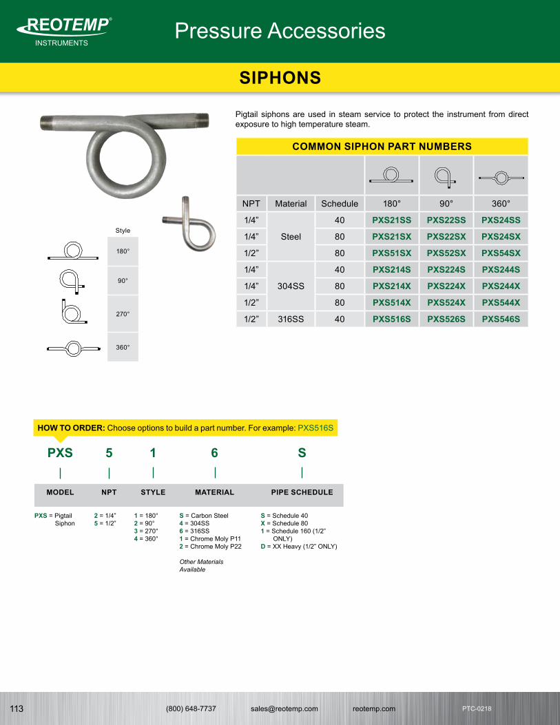
(800) 648-7737 [email protected] reotemp.com113
INSTRUMENTSMeasuring your world since 1965
®
PTC-0218
SIPHONS
Pressure Accessories
Pigtail siphons are used in steam service to protect the instrument from direct exposure to high temperature steam.
COMMON SIPHON PART NUMBERS
NPT Material Schedule 180° 90° 360°
1/4”
Steel
40 PXS21SS PXS22SS PXS24SS
1/4” 80 PXS21SX PXS22SX PXS24SX
1/2” 80 PXS51SX PXS52SX PXS54SX
1/4”
304SS
40 PXS214S PXS224S PXS244S
1/4” 80 PXS214X PXS224X PXS244X
1/2” 80 PXS514X PXS524X PXS544X
1/2” 316SS 40 PXS516S PXS526S PXS546S
MODEL
PXS = Pigtail Siphon
NPT
2 = 1/4”5 = 1/2”
STYLE
1 = 180°2 = 90°3 = 270° 4 = 360°
MATERIAL
S = Carbon Steel4 = 304SS6 = 316SS1 = Chrome Moly P112 = Chrome Moly P22
Other Materials Available
PIPE SCHEDULE
S = Schedule 40X = Schedule 801 = Schedule 160 (1/2”
ONLY)D = XX Heavy (1/2” ONLY)
Style
180°
90°
270°
360°
PXS 1 6 S5
HOW TO ORDER: Choose options to build a part number. For example: PXS516S
INSTRUMENTSMeasuring your world since 1965
®

(800) 648-7737 [email protected] reotemp.com 114
INSTRUMENTSMeasuring your world since 1965
®THERM
OM
ETERS
PTC-0218PTC-0218
INSTRUMENTSMeasuring your world since 1965
®
DIAL INDICATINGTHERMOMETERS
As one of the most experienced US manufacturers of temperature measurement products, REOTEMP has a broad product offering of high-quality dial indicating thermometers. REOTEMP offers rigid mount bimetallic thermometers, surface mount thermometers, remote reading thermometers, digital thermometers, and many other temperature indicating products for the industrial markets. Recognized for building durable, reliable products at industry leading lead times, you can count on REOTEMP to solve your temperature measurement needs.

(800) 648-7737 [email protected] reotemp.com115
INSTRUMENTSMeasuring your world since 1965
®
THERMO
METERS
PTC-0218
Accuracy ± 1% Full Scale (ASME B40.3)
Dial Size 3”, 4” or 5”
Dial Material Black marks on satin matte aluminum finish, Hi-Vis™, or white dial
Stem Length 2” to 80”
Stem Diameter 1/4” (Standard), 3/8” or 5/16”
Head, Bezel, Mounting Bushing, Stems
300 Series SS, 316SS (Optional)
Operating Conditions Head temperature should not exceed 200°F (150°F if silicone filled). Stem should not be exposed to continuous temperatures exceeding 50% over-range or 800°F (550°F if silicone filled).
Environmental Protection
IP67, NEMA 6 Rated (Hermetically sealed per ASME B40.3)
Lens Glass (Standard), Acrylic, Polycarbonate, Laminated Safety Glass or Tempered Glass
Immersion Minimum 2” in liquid, and 4” in gas for most ranges. Certain ranges require up to 4” in liquids & 5” in gas.
Mounting Connection 1/2” NPT (Standard), 1/4” NPT, 3/4” NPT, Plain Hex Bushing, or 1/2” BSPT
Temperature Sensing Area
Last 2” to 4” of the stem
Process Grade Thermometers
All dimensions are in inches.
All dimensions are in inches.
• Heavy-Duty Process Grade Design• Five Year Warranty • Made in the USA• Accuracy ± 1% Full Scale (ASME B40.3 Grade A) • Hermetically Sealed (ASME B40.3) • Standard External Reset for Calibration• Silicone Fillable for Vibration
REOTEMP’s Bimetal Thermometers are reliable and accurate temperature sensors requiring no electricity or wiring. Back Connect Thermometers are ideal for local, eye-level temperature readings in most process applications. They can be recalibrated with a turn of the calibration screw on the back of the dial. A variety of options are available for your specific process needs.
Fillable Accuracy
1%
Custom Logo
FEATURES / BENEFITS
SPECIFICATIONS
Dials
™
B40.3
Fixed Union
Standard Dimensions
BACK CONNECT BIMETAL THERMOMETER
STEM LENGTH
∅3 (Model A)∅4 (Model C)∅5 (Model B)
.75
∅1/4 (STD)
RESET
.4
1/2 NPT (STD)
P.6 - BACK CONNECT BIMETAL THERMOMETER
∅3 (Model A)∅4 (Model C)∅5 (Model B)
.75
∅1/4 (STD)
RESET
1/2 NPT (STD)
1.75 STEM LENGTH
Fixed Union
Standard Dimensions
STEM LENGTH
∅3 (Model A)∅4 (Model C)∅5 (Model B)
.75
∅1/4 (STD)
RESET
.4
1/2 NPT (STD)
P.6 - BACK CONNECT BIMETAL THERMOMETER
∅3 (Model A)∅4 (Model C)∅5 (Model B)
.75
∅1/4 (STD)
RESET
1/2 NPT (STD)
1.75 STEM LENGTH
Fixed Union
Standard Dimensions

(800) 648-7737 [email protected] reotemp.com 116
INSTRUMENTSMeasuring your world since 1965
®THERM
OM
ETERS
PTC-0218PTC-0218
ü Check Stockü Configure Part #
ü Get Priceü Generate a Custom Engineering DrawingVisit reotemp.com
Process Grade Thermometers
BACK CONNECT BIMETAL THERMOMETER
HOW TO ORDERHOW TO ORDER: Choose options to build a part number. For example: AA0251F23-SF
AA 025 1 F23 -SF
DIALSIZE
Standard ModelAA = 3” Dial w/ ResetCC = 4” Dial w/ ResetBB = 5” Dial w/ Reset
Non-Reset ModelRR = 3” Dial w/o ResetCN = 4” Dial w/o ResetSS = 5” Dial w/o Reset
STEM LENGTH
025 = 2.5”040 = 4” 060 = 6”090 = 9”120 = 12”150 = 15”180 = 18”240 = 24”300 = 30”360 = 36”
Note: Intermediate stem lengths available up to 80”.
Millimeter Stem LengthsM???? = Use a code beginning in M to specify a mm stem length ex: 100mm = M0100
CONNECTION
1 = 1/2” NPT4 = 1/4” NPT5 = 3/4” NPT AdapterX = Plain Unthreaded
Hex BushingB = 1/2” BSPTU = 1/2” NPT Union
TEMPERATURE RANGE
Fahrenheit RangesF23 = -40°F to 160°F *F55 = 25°F to 125°FF43 = 0°F to 200°F F47 = 0°F to 250°F F63 = 50°F to 300°F F67 = 50°F to 500°F F69 = 50°F to 550°F F81 = 150°F to 750°F F85 = 200°F to 1000°F
Celsius RangesC23 = -40°C to 70°C C55 = 0°C to 50°C*C43 = 0°C to 100°C C47 = -20°C to 120°C C59 = 0°C to 150°C C67 = 0°C to 250°C C69 = 0°C to 300°C C73 = 0°C to 400°C C85 = 100°C to 500°C
Dual Scale RangesD23 = -40°F to 160°F & -40°C to 70°C*D55 = 25°F to 125°F & -5°C to 50°CD43 = 0°F to 200°F & -10°C to 90°CD47 = 0°F to 250°F & -20°C to 120°CD63 = 50°F to 300°F & 10°C to 150°CD67 = 50°F to 500°F & 10°C to 260°CD69 = 50°F to 550°F & 10°C to 290°CD81 = 150°F to 750°F & 70°C to 400°CD85 = 200°F to 1000°F & 100°C to 500°C
*Not available in 2.5” stem.
For Additional Ranges See Master Range Code Sheet on Page 141
OPTIONS
General Options-3H = 316 SS Head and Bezel-PS = Pointed Stem -S3 = 3/8” diameter Stem-F5 = 5/16” diameter Stem (Not Available
with 316SS Stem)-SF = Silicone Filled-SS = 316 Stainless Stem-WD = White Dial-HV = Hi-Vis™ Dial-NL = No Logo Dial-CB = Color Bands-PI = Color Pie-CL = Custom Logo Dial
Window Options (Standard is Glass)-MM = Min-Max Pointer (Plastic Lens)-PC = Acrylic Window-PY = Polycarbonate Window-TG = Tempered Glass Window-SG = Laminated Safety Glass
Calibration Cert. Options-R1 = One Point Calibration Cert
(REOTEMP Chooses Points)-R3 = Three Point Calibration Cert
(REOTEMP Chooses Points)-C1 = One Point Calibration Cert
(Customer Chooses Points)-C3 = Three Point Calibration Cert
(Customer Chooses Points)
Tags and Accessories-TS = Tag, Stainless-TP = Tag, Paper-AS = Adapts Bimet to 1-1/4-18 industrial
socket-HT = Heat Transfer Compound
For Additional Options See Page 139
For Thermowells See Pages 160-166
Note: Thermowells should be used whenever the stem or bulb would be exposed to pressure, corrosion, velocity, abrasion or shear forces. Thermowells also make it possible to remove the thermometer without losing pressure or the contents of the process.

(800) 648-7737 [email protected] reotemp.com117
INSTRUMENTSMeasuring your world since 1965
®
THERMO
METERS
PTC-0218
• Heavy-Duty Process Grade Design• Five Year Warranty• Made in the USA• Dial is Adjustable to Any Position for Easy Viewing• Accuracy ± 1% Full Scale. (ASME B40.3) • Hermetically Sealed (ASME B40.3)• Standard External Reset for Easy Calibration• Silicone Fillable for Vibration
REOTEMP’s Bimetal Thermometers are reliable and accurate temperature sensors requiring no electricity or wiring. Adjustable Angle Thermometers allow for easy temperature monitoring from any position and they are ideal for local indication. They can be recalibrated with a turn of the calibration screw on the back of the dial.
Fillable Accuracy
1%
Custom Logo
FEATURES / BENEFITS
Dials
™
B40.3
SPECIFICATIONS
Ø 3 (Model L)Ø 4 (Model M)Ø 5 (Model J)
.75
1.4
STEMLENGTH
1.6
3.1
P.8 - ADJUSTABLE ANGLE BIMETAL THERMOMETER
RESET
All dimensions are in inches.
Accuracy ± 1% Full Scale (ASME B40.3)
Dial Size 3”, 4” or 5”
Dial Material Black marks on satin matte aluminum finish, Hi-Vis™, or white dial
Stem Length 2” to 80”
Stem Diameter 1/4” (Standard), 3/8” or 5/16”
Head, Bezel, Mounting Bushing, Stems
300 Series SS, 316SS (Optional)
Operating Conditions Head temperature should not exceed 200°F (150°F if silicone filled). Stem should not be exposed to continuous temperatures exceeding 50% over-range or 800°F (550°F if silicone filled).
Environmental Protection
IP67, NEMA 6 Rated (Hermetically sealed per ASME B40.3)
Lens Glass (Standard), Acrylic, Polycarbonate, Laminated Safety Glass or Tempered Glass
Immersion Minimum 2” in liquid, and 4” in gas for most ranges. Certain ranges require up to 4” in liquids & 5” in gas.
Mounting Connection 1/2” NPT (Standard), 1/4” NPT, 3/4” NPT, Plain Hex Bushing, or 1/2” BSPT
Temperature Sensing Area
Last 2” to 4” of the stem
Process Grade Thermometers
ADJUSTABLE ANGLE BIMETAL THERMOMETER
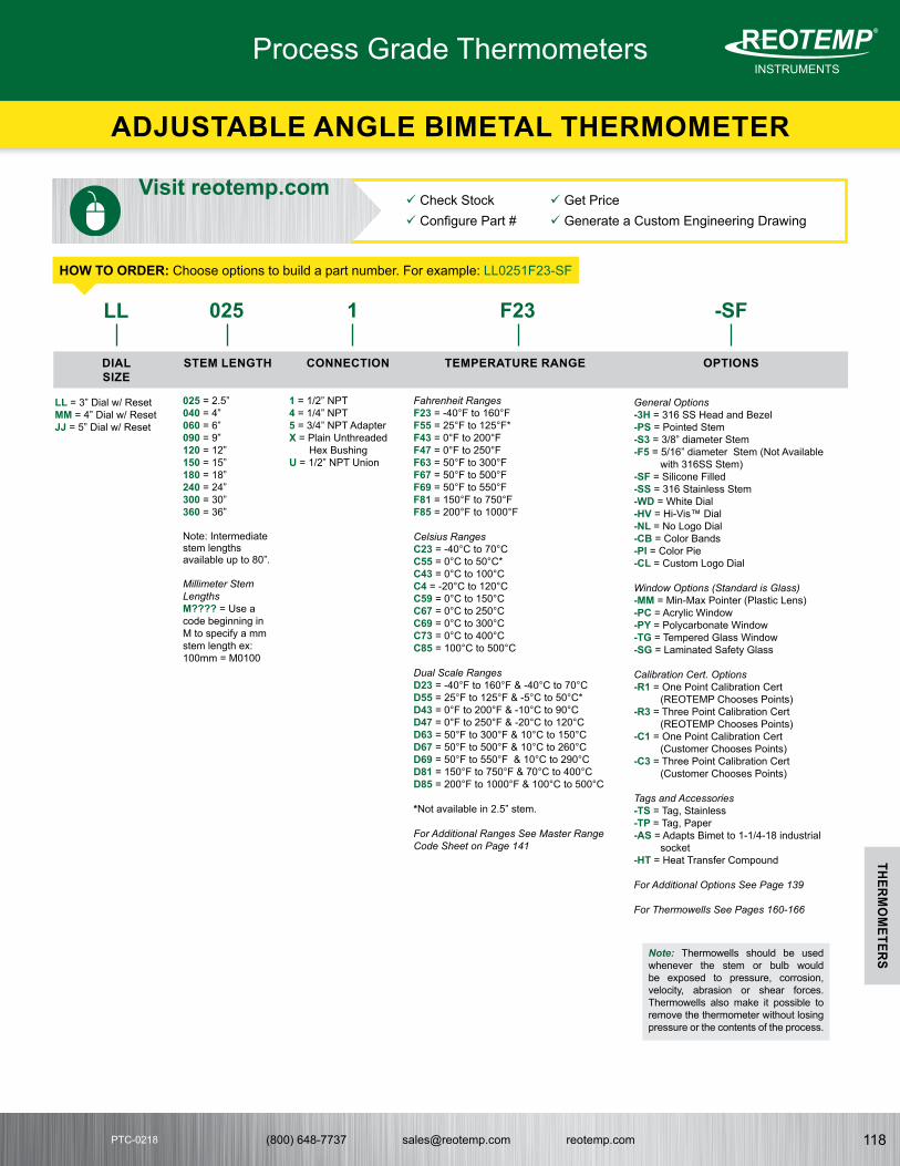
(800) 648-7737 [email protected] reotemp.com 118
INSTRUMENTSMeasuring your world since 1965
®THERM
OM
ETERS
PTC-0218PTC-0218
HOW TO ORDERHOW TO ORDER: Choose options to build a part number. For example: LL0251F23-SF
LL 025 1 F23 -SF
DIALSIZE
LL = 3” Dial w/ ResetMM = 4” Dial w/ ResetJJ = 5” Dial w/ Reset
STEM LENGTH
025 = 2.5”040 = 4” 060 = 6”090 = 9”120 = 12”150 = 15”180 = 18”240 = 24”300 = 30”360 = 36”
Note: Intermediate stem lengths available up to 80”.
Millimeter Stem LengthsM???? = Use a code beginning in M to specify a mm stem length ex: 100mm = M0100
CONNECTION
1 = 1/2” NPT4 = 1/4” NPT5 = 3/4” NPT AdapterX = Plain Unthreaded
Hex BushingU = 1/2” NPT Union
TEMPERATURE RANGE
Fahrenheit RangesF23 = -40°F to 160°F F55 = 25°F to 125°F* F43 = 0°F to 200°F F47 = 0°F to 250°F F63 = 50°F to 300°F F67 = 50°F to 500°F F69 = 50°F to 550°F F81 = 150°F to 750°F F85 = 200°F to 1000°F
Celsius RangesC23 = -40°C to 70°C C55 = 0°C to 50°C*C43 = 0°C to 100°C C4 = -20°C to 120°C C59 = 0°C to 150°C C67 = 0°C to 250°C C69 = 0°C to 300°C C73 = 0°C to 400°C C85 = 100°C to 500°C
Dual Scale RangesD23 = -40°F to 160°F & -40°C to 70°CD55 = 25°F to 125°F & -5°C to 50°C*D43 = 0°F to 200°F & -10°C to 90°CD47 = 0°F to 250°F & -20°C to 120°CD63 = 50°F to 300°F & 10°C to 150°CD67 = 50°F to 500°F & 10°C to 260°CD69 = 50°F to 550°F & 10°C to 290°CD81 = 150°F to 750°F & 70°C to 400°CD85 = 200°F to 1000°F & 100°C to 500°C
*Not available in 2.5” stem.
For Additional Ranges See Master Range Code Sheet on Page 141
OPTIONS
General Options-3H = 316 SS Head and Bezel-PS = Pointed Stem -S3 = 3/8” diameter Stem-F5 = 5/16” diameter Stem (Not Available
with 316SS Stem)-SF = Silicone Filled-SS = 316 Stainless Stem-WD = White Dial-HV = Hi-Vis™ Dial-NL = No Logo Dial-CB = Color Bands-PI = Color Pie-CL = Custom Logo Dial
Window Options (Standard is Glass)-MM = Min-Max Pointer (Plastic Lens)-PC = Acrylic Window-PY = Polycarbonate Window-TG = Tempered Glass Window-SG = Laminated Safety Glass
Calibration Cert. Options-R1 = One Point Calibration Cert
(REOTEMP Chooses Points)-R3 = Three Point Calibration Cert
(REOTEMP Chooses Points)-C1 = One Point Calibration Cert
(Customer Chooses Points)-C3 = Three Point Calibration Cert
(Customer Chooses Points)
Tags and Accessories -TS = Tag, Stainless-TP = Tag, Paper-AS = Adapts Bimet to 1-1/4-18 industrial
socket-HT = Heat Transfer Compound
For Additional Options See Page 139
For Thermowells See Pages 160-166
Note: Thermowells should be used whenever the stem or bulb would be exposed to pressure, corrosion, velocity, abrasion or shear forces. Thermowells also make it possible to remove the thermometer without losing pressure or the contents of the process.
ü Check Stockü Configure Part #
ü Get Priceü Generate a Custom Engineering Drawing
Visit reotemp.com
Process Grade Thermometers
ADJUSTABLE ANGLE BIMETAL THERMOMETER

(800) 648-7737 [email protected] reotemp.com119
INSTRUMENTSMeasuring your world since 1965
®
THERMO
METERS
PTC-0218
• Heavy-Duty Process Grade Design• Five Year Warranty• Made in the USA• Accuracy ± 1% Full Scale. (ASME B40.3)• Hermetically Sealed (ASME B40.3)• Standard External Reset for Easy Calibration• OEM Logo Dials/Custom Dials• Silicone Fillable for Vibration
REOTEMP’s Bimetal Thermometers are reliable and accurate temperature sensors requiring no electricity or wiring. Bottom Connect Thermometers are ideal for side and elevated installations on tops or sides of tanks or pipes and are ideal for local indication. They can be recalibrated with a turn of the calibration screw on the back of the dial. A variety of options are available for your specific process needs.
Fillable Accuracy
1%
Custom Logo
FEATURES / BENEFITS
Dials
™
B40.3
SPECIFICATIONS
All dimensions are in inches..
Accuracy ± 1% Full Scale (ASME B40.3)
Dial Size 3”, 4” or 5”
Dial Material Black marks on satin matte aluminum finish, Hi-Vis™, or white dial
Stem Length 2” to 80”
Stem Diameter 1/4” (Standard), 3/8” or 5/16”
Head, Bezel, Mounting Bushing, Stems
300 Series SS, 316SS (Optional)
Operating Conditions Head temperature should not exceed 200°F (150°F if silicone filled). Stem should not be exposed to continuous temperatures exceeding 50% over-range or 800°F (550°F if silicone filled).
Environmental Protection
IP67, NEMA 6 Rated (Hermetically sealed per ASME B40.3)
Lens Glass (Standard), Acrylic, Polycarbonate, Laminated Safety Glass or Tempered Glass
Immersion Minimum 2” in liquid, and 4” in gas for most ranges. Certain ranges require up to 4” in liquids & 5” in gas.
Mounting Connection 1/2” NPT (Standard), 1/4” NPT, 3/4” NPT, Plain Hex Bushing, or 1/2” BSPT
Temperature Sensing Area
Last 2” to 4” of the stem
Process Grade Thermometers
BOTTOM CONNECT BIMETAL THERMOMETER
P.10 - BOTTOM CONNECT BIMETAL THERMOMETER
StemLength
.75
.6∅1/4
∅3 (Model XR)∅4 (Model YY)∅5 (Model VR)
RESET
100
50REOTEMP
200
2500°F
150
12
39
6 (STD)

(800) 648-7737 [email protected] reotemp.com 120
INSTRUMENTSMeasuring your world since 1965
®THERM
OM
ETERS
PTC-0218PTC-0218
HOW TO ORDERHOW TO ORDER: Choose options to build a part number. For example: XR0251F23-SF
XR 025 1 F23 -SF
DIALSIZE
Standard Model
XR = 3” Dial w/ ResetYY = 4” Dial w/ ResetVR = 5” Dial w/ Reset
Non-Reset Model
XX = 3” Dial w/o ResetYN = 4” Dial w/o ResetVV = 5” Dial w/o Reset
STEM LENGTH
025 = 2.5”040 = 4” 060 = 6”090 = 9”120 = 12”150 = 15”180 = 18”240 = 24”300 = 30”360 = 36”
Note: Intermediate stem lengths available up to 80”.
Millimeter Stem LengthsM???? = Use a code beginning in M to specify a mm stem length ex: 100mm = M0100
CONNECTION
1 = 1/2” NPT4 = 1/4” NPT5 = 3/4” NPT AdapterX = Plain Unthreaded
Hex BushingU = 1/2” NPT Union
TEMPERATURE RANGE
Fahrenheit RangesF23 = -40°F to 160°F F55 = 25°F to 125°F* F43 = 0°F to 200°F F47 = 0°F to 250°F F63 = 50°F to 300°F F67 = 50°F to 500°F F69 = 50°F to 550°F F81 = 150°F to 750°F F85 = 200°F to 1000°F
Celsius RangesC23 = -40°C to 70°C C55 = 0°C to 50°C*C43 = 0°C to 100°C C4 = -20°C to 120°C C59 = 0°C to 150°C C67 = 0°C to 250°C C69 = 0°C to 300°C C73 = 0°C to 400°C C85 = 100°C to 500°C
Dual Scale RangesD23 = -40°F to 160°F & -40°C to 70°CD55 = 25°F to 125°F & -5°C to 50°C*D43 = 0°F to 200°F & -10°C to 90°CD47 = 0°F to 250°F & -20°C to 120°CD63 = 50°F to 300°F & 10°C to 150°CD67 = 50°F to 500°F & 10°C to 260°CD69 = 50°F to 550°F & 10°C to 290°CD81 = 150°F to 750°F & 70°C to 400°CD85 = 200°F to 1000°F & 100°C to 500°C
*Not available in 2.5” stem.
For Additional Ranges See Master Range Code Sheet on Page 141
OPTIONS
General Options-3H = 316 SS Head and Bezel-PS = Pointed Stem -S3 = 3/8” diameter Stem-F5 = 5/16” diameter Stem (Not Available
with 316SS Stem)-SF = Silicone Filled-SS = 316 Stainless Stem-WD = White Dial-HV = Hi-Vis™ Dial-NL = No Logo Dial-CB = Color Bands-PI = Color Pie-CL = Custom Logo Dial
Window Options (Standard is Glass)-MM = Min-Max Pointer (Plastic Lens)-PC = Acrylic Window-PY = Polycarbonate Window-TG = Tempered Glass Window-SG = Laminated Safety Glass
Calibration Cert. Options-R1 = One Point Calibration Cert
(REOTEMP Chooses Points)-R3 = Three Point Calibration Cert
(REOTEMP Chooses Points)-C1 = One Point Calibration Cert
(Customer Chooses Points)-C3 = Three Point Calibration Cert
(Customer Chooses Points)
Tags and Accessories-TS = Tag, Stainless-TP = Tag, Paper-AS = Adapts Bimet to 1-1/4-18 industrial
socket-HT = Heat Transfer Compound
Mounting Orientation-99 = 9 O’Clock Stem (Left Side)-33 = 3 O’Clock Stem (Right Side)-12 = 12 O’Clock Stem (Upside Down)
For Additional Options See Page 139
For Thermowells See Pages 160-166
Note: Thermowells should be used whenever the stem or bulb would be exposed to pressure, corrosion, velocity, abrasion or shear forces. Thermowells also make it possible to remove the thermometer without losing pressure or the contents of the process.
Mounting Orientation
ü Check Stockü Configure Part #
ü Get Priceü Generate a Custom Engineering DrawingVisit reotemp.com
Process Grade Thermometers
BOTTOM CONNECT BIMETAL THERMOMETER
P.10 - BOTTOM CONNECT BIMETAL THERMOMETER
StemLength
.75
.6∅1/4
∅3 (Model XR)∅4 (Model YY)∅5 (Model VR)
RESET
100
50REOTEMP
200
2500°F
150
12
39
6 (STD)

(800) 648-7737 [email protected] reotemp.com121
INSTRUMENTSMeasuring your world since 1965
®
THERMO
METERS
PTC-0218
• Five Year Warranty• Made in the USA • 3-A Conformance Certificate Included• Accuracy ± 1% Full Scale. (ASME B40.3) • Hermetically Sealed (ASME B40.3) • Standard External Reset • Tri-Clamp® Design for Fast Installation and Removal• Silicone Fillable for Vibration
REOTEMP’s Sanitary Bimetal Thermometers are specially designed for direct insertion into sanitary process applications when a standard thermowell is not specified or the process environment is not exposed to pressure. Sanitary thermometers are ideal for the food, beverage and pharmaceutical industries.
Fillable Accuracy
1%
Custom Logo
FEATURES / BENEFITS
Dials
™
B40.3
SPECIFICATIONS
Certified
Sanitary Flange Size
Diameter in Inches “C”
3/4” .98"
1” 2"
1.5” 2"
2” 2.5"
2.5” 3"
3” 3.6"
P.12 SANITARY BIMETAL THERMOMETER
STEM LENGTH
DIALSIZE
�Ø1/4TRI-CLAMP SIZE “C”
RESET
All dimensions are in inches.
Accuracy ± 1% Full Scale (ASME B40.3)
Dial Size 3”, 4” or 5”
Dial Material Black marks on satin matte aluminum finish, Hi-Vis™, or white dial
Stem Length 2” to 80”
Stem Diameter 1/4” (Standard), or 3/8”
Head, Bezel, Mounting Bushing
300 Series SS, or 316SS (Optional)
Stem & Tri-Clamp 316SS
Operating Conditions Head temperature should not exceed 200°F (150°F if silicone filled). Stem should not be exposed to continuous temperatures exceeding 50% over-range or 800°F (550°F if silicone filled).
Environmental Protection
IP67, NEMA 6 Rated (Hermetically sealed per ASME B40.3)
Lens Polycarbonate(Standard), Glass, Acrylic, Laminated Safety Glass or Tempered Glass
Immersion Minimum 2” in liquid, and 4” in gas for most ranges. Certain ranges require up to 4” in liquids & 5” in gas.
Mounting Connection Sanitary Tri-Clamp®
Temperature Sensing Area
Last 2” to 4” of the stem
Process Grade Thermometers
SANITARY BIMETAL THERMOMETER

(800) 648-7737 [email protected] reotemp.com 122
INSTRUMENTSMeasuring your world since 1965
®THERM
OM
ETERS
PTC-0218PTC-0218
HOW TO ORDERHOW TO ORDER: Choose options to build a part number. For example: XR025CF23-SF
XR 025 C F23 -SF
DIALSIZE
Standard Model with Reset
Non-Reset Model
STEM LENGTH
025 = 2.5”040 = 4” 060 = 6”090 = 9”120 = 12”150 = 15”180 = 18”240 = 24”300 = 30”360 = 36”
Note: Intermediate stem lengths available up to 80”.
Millimeter Stem LengthsM???? = Use a code beginning in M to specify a mm stem length ex: 100mm = M0100
CONNECTION
SanitaryC = 1.5” Tri-Clamp®
L = 2” Tri-Clamp®
A = 2.5” Tri-Clamp®
P = 3” Tri-Clamp®
M = 3/4” Tri-Clamp®
Other sanitary flangesavailable.
TEMPERATURE RANGE
Fahrenheit RangesF23 = -40°F to 160°F F55 = 25°F to 125°F* F43 = 0°F to 200°F F47 = 0°F to 250°F F63 = 50°F to 300°F F67 = 50°F to 500°F F69 = 50°F to 550°F F81 = 150°F to 750°F F85 = 200°F to 1000°F
Celsius RangesC23 = -40°C to 70°C C55 = 0°C to 50°C*C43 = 0°C to 100°C C4 = -20°C to 120°C C59 = 0°C to 150°C C67 = 0°C to 250°C C69 = 0°C to 300°C C73 = 0°C to 400°C C85 = 100°C to 500°C
Dual Scale RangesD23 = -40°F to 160°F & -40°C to 70°CD55 = 25°F to 125°F & -5°C to 50°C*D43 = 0°F to 200°F & -10°C to 90°CD47 = 0°F to 250°F & -20°C to 120°CD63 = 50°F to 300°F & 10°C to 150°CD67 = 50°F to 500°F & 10°C to 260°CD69 = 50°F to 550°F & 10°C to 290°CD81 = 150°F to 750°F & 70°C to 400°CD85 = 200°F to 1000°F & 100°C to 500°C
*Not available in 2.5” stem.
For Additional Ranges See Master Range Code Sheet on Page 141
OPTIONS
General Options-3H = 316 SS Head and Bezel-PS = Pointed Stem -S3 = 3/8” diameter Stem-SF = Silicone Filled-WD = White Dial-HV = Hi-Vis™ Dial-NL = No Logo Dial-CB = Color Bands-PI = Color Pie-CL = Custom Logo Dial
Window Options (Standard is Glass)-MM = Min-Max Pointer (Plastic
Lens)-PC = Acrylic Window-PY = Polycarbonate Window-TG = Tempered Glass Window-SG = Laminated Safety Glass
Calibration Cert. Options-R1 = One Point Calibration Cert
(REOTEMP Chooses Points)-R3 = Three Point Calibration Cert
(REOTEMP Chooses Points)-C1 = One Point Calibration Cert
(Customer Chooses Points)-C3 = Three Point Calibration Cert
(Customer Chooses Points)
Tags and Accessories-TS = Tag, Stainless-TP = Tag, Paper-AS = Adapts Bimet to 1-1/4-18
industrial socket-HT = Heat Transfer Compound
For Additional Options See Page 139
For Thermowells See Pages 160-166
Dial Size 3” 4” 5”
Back Connect AA CC BB
Adjustable Angle LL MM JJ
Bottom Connect XR YY VR
Dial Size 3” 4” 5”
Back Connect RR CN SS
Bottom Connect XX YN VN
Note: Thermowells should be used whenever the stem or bulb would be exposed to pressure, corrosion, velocity, abrasion or shear forces. Thermowells also make it possible to remove the thermometer without losing pressure or the contents of the process.
ü Check Stockü Configure Part #
ü Get Priceü Generate a Custom Engineering DrawingVisit reotemp.com
Tri-Clamp® is a registered trademark of Alpha Laval Inc.
Process Grade Thermometers
SANITARY BIMETAL THERMOMETER

(800) 648-7737 [email protected] reotemp.com123
INSTRUMENTSMeasuring your world since 1965
®
THERMO
METERS
PTC-0218
• Increase Reliability with Independent Local and Remote Reading (Up to 1000°F) from One Thermowell
• Redundant Sensors for Simple, Effective Calibration or Spot Checking Without Removing the Instrument from the Thermowell
• Interchangeable with Existing Thermometer, RTD, or Thermocouple
REOTEMP’s Dual Mode Thermometer (DMT) is a convenient, multi-purpose indicator for local and remote temperature monitoring. This rugged dual-sensor system puts TWO independent sensors in ONE THERMOWELL, and allows easy tie-in to process controls. Both sensors are NIST traceable. Special sensor encapsulation and optional liquid filling make the DMT the most rugged, durable instrument of its kind.
Bimetal Thermometer• Local Easy-to-Read
Temperature Indication• Self-Actuating, Dampened
Bimetal Helix Sensor• Hermetically sealed per ASME
B40.3 (3/8” stem only)
Thermocouple or RTD• Remote Indication & Data
Acquisition for Process Control• Choice of Connection Styles• 4-20mA Transmitter Output
Available
Fillable Accuracy
1%
Custom Logo
FEATURES / BENEFITS
Dials
™
SPECIFICATIONS
Tri-Clamp® is a registered trademark of Alpha Laval Inc.
Made in the USA
Case & Bezel 304SS (Standard), 316SS
Case Style Back or Adjustable Angle Connection
Dial Size 3”, 4”, or 5”
Process Connections 1/2” NPT (Standard) or 1/2” NPT Union
External Reset Slotted Hex Screw
Lens Glass (Standard), Plastic or Tempered Glass
Hermetic Seal Bimetal Thermometer per ASME B40.3 (3/8” Stem Only)
Stem Material 304SS (Standard) or 316SS (Optional)
Stem Diameter 3/8" or 1/4"
Stem Length 2-1/2” to 36”
Bimetal Ranges Standard Ranges and Divisions up to 800°F (538°C), See Page 141 for Complete Range Code Guide
Bimetal Over-range 50% Over Range to 550°F, 1000°F Max
Bimetal Accuracy ± 1% of Full Scale
TC/RTD Temperature Limits
-100°F to 1000°F (Thermocouple), -100°F to 600°F (RTD - DM4 Model), -100°F to 900°F (RTD - DMT Model)
Thermocouple Type K Grounded Junction (Standard), Types T, E, J, and Ungrounded
Thermocouple Accuracy
Type K ± 2.2°C or 0.75% (-200°C to 1260°C), Whichever is Greater, Others Available Upon Request
RTD Pt/385/Class B 100Ω (Std.), Others Available
RTD Accuracy 0.12%°C (Standard), Others Available
Head Orientation RTD or Thermocouple Head is Mounted to the Right of the Bimetal Thermometer
Thermowell Model DMT Fits Any Standard 0.385” Bore Thermowell or Model DM4 Fits 0.260” Bore
Process Grade Thermometers
DUAL MODE THERMOMETER

(800) 648-7737 [email protected] reotemp.com 124
INSTRUMENTSMeasuring your world since 1965
®THERM
OM
ETERS
PTC-0218PTC-0218
HOW TO ORDERHOW TO ORDER: Choose options to build a part number. For example: DMTA040F23TKAA-HV
TA 040 F23
STYLE & STEMDIAMETER
3/8” StemTA = 3” Back ConnectTC = 4” Back ConnectTB = 5” Back ConnectTL = 3” Adjustable-AngleTM = 4” Adjustable-AngleTJ = 5” Adjustable-Angle
1/4” Stem4A = 3” Back Connect4C = 4” Back Connect4B = 5” Back Connect4L = 3” Adjustable-Angle4M = 4” Adjustable-Angle4J = 5” Adjustable-Angle
STEM LENGTH
025 = 2.5”*040 = 4” 060 = 6”090 = 9”120 = 12”150 = 15”180 = 18”240 = 24”300 = 30”360 = 36”
*Only available on 3/8” stem diameter.
Note: Intermediate stem lengths available up to 80”.
Millimeter Stem LengthsM???? = Use a code beginning in M to specify a mm stem length ex: 100mm = M0100
TEMPERATURE RANGE
Fahrenheit Ranges F23 = -40°F to 160°F F55 = 25°F to 125°F*F43 = 0°F to 200°F F47 = 0°F to 250°F F53 = 20°F to 240°F F63 = 50°F to 300°F F69 = 50°F to 550°F
*Not available in 2.5” stem.
For Additional Ranges See Master Range Code Sheet on Page 141
OPTIONS
General Options-HV = Hi-Vis™ Dial-UF = Fixed Union-US = Sliding Union-3H = 316 SS Head and
Bezel-SF = Silicone Filled (Max
500°F)-SS = 316 Stainless Stem-NL = No Logo Dial-CL = Custom Logo Dial
Window Options (Standard is Glass)-MM = Min-Max Pointer
(Plastic Lens)-PC = Acrylic Window-PY = Polycarbonate
Window-TG = Tempered Glass
Window
Sanitary Connections-SC = 1.5" or 1" Tri-Clamp-SL = 2" Tri-Clamp-SA = 2.5" Tri-Clamp-SP = 3" Tri-Clamp
Calibration Cert. Options-R1 = One Point Calibration
Cert (REOTEMP Chooses Points)
-R3 = Three Point Calibration Cert (REOTEMP Chooses Points)
Tags and Accessories-TS = Tag, Stainless-AS = Adapts Bimet to 1-1/4-
18 industrial socket-HT = Heat Transfer Com-
pound
For Additional Options See Page 139
For Thermowells See Pages 160-166
SENSOR
Thermocouple(Single, Grounded)TK = Type KTJ = Type JTE = Type ETT = Type T
Thermocouple(Single, Ungrounded)UK = Type KUJ = Type JUE = Type EUT = Type T
Thermocouple(Dual, Grounded)TKK = Type KTJJ = Type JTEE = Type ETTT= Type T
Thermocouple(Dual, Ungrounded)UKK = Type KUJJ = Type JUEE = Type EUTT = Type T
RTD (Single)RC = RTD, Pt. 100
ohm, 3-wire (Max. 600°F - DM4) (Max. 900°F - DMT)
HEADS/OUTPUTCONNECTIONS
A = Cast Iron BlackC = Poly Plastic BlackE = Explosion Proof
AluminumG = 316SSH = Cast AluminumM = Aluminum Flip TopI = Blue Epoxy-Coated
AluminumJ = Explosion Proof
316SSS = Poly Plastic WhiteT = ATEX Explosion
Proof AluminumZ = Window Explosion
Proof (Digital Display Required)
EC = 1/2” NPT Male Electrical Connection w/ Lead Wire (See Drawing & Ignore Electrical Connection Section)
ELECTRICAL CONNECTION
A = Terminal BlockN = No Terminal
Block, 6” LeadsT = 4-20mA XmtrD = 4-20mA Hart
XmtrB = 4-20mA Xmtr w/
Display*H = 4-20mA Hart
Xmtr w/ Display*
*Only available with Z Head
TK A A -HVDM
Note: Thermowells should be used whenever the stem or bulb would be exposed to pressure, corrosion, velocity, abrasion or shear forces. Thermowells also make it possible to remove the thermometer without losing pressure or the contents of the process.
P.15 DUAL MODE THERMOMETER
Optional Electrical Connectionwith Lead Wire (EC)
Ø3”, Ø4”, Ø5”
4.8”
1/2”NPT
STEMLENGTH
Ø3/8” or Ø1/4”
P.15 DUAL MODE THERMOMETER
Optional Electrical Connectionwith Lead Wire (EC)
Ø3”, Ø4”, Ø5”
4.8”
1/2”NPT
STEMLENGTH
Ø3/8” or Ø1/4”
ü Check Stockü Configure Part #
ü Get Priceü Generate a Custom Engineering Drawing
Visit reotemp.com
Process Grade Thermometers
DUAL MODE THERMOMETER

(800) 648-7737 [email protected] reotemp.com125
INSTRUMENTSMeasuring your world since 1965
®
THERMO
METERS
PTC-0218
• An Improved Dual Element Alternative to Standard MIL-I-17244E Bimetal Thermometer
• Reinforced Construction Designed for Use on Navy Ships and Other Demanding Applications
• Independent Local and Remote Reading (Up to 1000°F) from One Thermowell
• Redundant Sensors for Simple, Effective Calibration or Spot Checking Without Removing the Instrument from the Thermowell
• Interchangeable with Existing Thermometer, RTD, or Thermocouple
• DMS Model is Navy Mil-Spec Approved (MIL-S-901D & MIL-STD-167-1A)
REOTEMP’s Navy Type Dual Mode Thermometer combines a bimetal thermometer and RTD sensor into the same stem. This provides local indication and remote reading from a single instrument. The unit has a heavy duty, all-welded construction built to withstand tough shock and high vibration environments. The DMS option meets the requirements for MIL-S-901D and MIL-STD-167-1A for navy mil-spec shock and vibration.
Made in the USA
Approvals (Optional) MIL-S 901D (Shock) and MIL-STD-167 (Vibration)
Sensor 100Ω Platinum 3 WireRTD
RTD Temperature Range
-40°F to 1000°F
Accuracy RTD: Class BBimetal: ± 1% of Scale
Electrical Connection Mil Connector MS3451W10SL-3P 3 Pin Electrical Cable Connection
Dial Range All Standard Bimetal Ranges. See page 141 for a Complete Range Code Guide
Dial Size 3” or 5”
Process Connections 3/4"-28 Thread, 1/2" NPT, or 7/8" 14 with Fixed Swivel Union and Navy Collar
Stem Diameter 3/8" DMN & DMS Models, 1/4" for DMC
Lens Polycarbonate
Stem Material 304SS
External Dial Reset Slotted Hex Screw
Process Grade Thermometers
NAVY TYPE DUAL MODE THERMOMETER
Measuring your world since 1965
Features/Benefits:
Combines a bimetal element for local indication and a 3 wire 100 ohm platinum RTD for remote
Back or bottom connection with various stem lengths.
Ph (800)648-7737Fx (858)784-0720 www.reotemp.com
Distributed by:
REOTEMP Instruments San Diego, CA U.S.A.
SERIES RTDX
Applications/Markets: Military Harsh commercial applications
Part builder on back
Mil-Spec Dual Mode Thermometer INSTRUMENTSMeasuring your world since 1965
Series DMS
3 wire, 100ohm platinum RTD
All Std. bimetal ranges
Mil Spec 3 pin electrical cable (MS3456W10SL-3P)connector
3/8”
304SS
MIL-S-901D (shock) and MIL-STD-167
Slotted hex screw
Polycarbonate
Sensor:
Dial Temperature Range: RTD Temperature Range:
Electrical Connection:
Stem Diameter:Stem Material:
Accuracy:
Mil Spec. Approvals:
External Dial Reset:Lens:
Specifications:
Navy Mil Spec Approved
Designed for use on Navy ships and other demanding commercial applications.
An improved dual element alternative to standard MIL-I-17244E bimetal thermometer.
-40 F to 1000 F
Std. 3/4” - 28 threadProcess Connection:
(vibration)
REOTEMP
MIL CONNECTOR#MS3451W10SL-3POR EQIVALENT
indication.
DMSPB.0910
INSTRUMENTS
STEM
3/4”-28UNS-2A
1-9/16
6-5/8 (MAX)
Ø 3-3/64
1-13/16
7/8 HEX
+-1% of scaleBimet = RTD= Class B
The Mil-Spec. Dual Mode Thermometer combines a bimetal thermometer and RTD sensor into thesame stem. This provides local indication and remote reading from a single instrument. The 3/8” stem willfit existing thermowells. This unit has a heavy duty, all-welded construction built to withstand tough shock and vibrationenvironments and is qualified by the Navy to mil-spec shock and vibration requirements MIL-S-901D andMIL-STD-167-1A.
FEATURES / BENEFITS
SPECIFICATIONS

(800) 648-7737 [email protected] reotemp.com 126
INSTRUMENTSMeasuring your world since 1965
®THERM
OM
ETERS
PTC-0218PTC-0218
Approvals (Optional) MIL-S 901D (Shock) and MIL-STD-167 (Vibration)
Sensor 100Ω Platinum 3 WireRTD
RTD Temperature Range
-40°F to 1000°F
Accuracy RTD: Class BBimetal: ± 1% of Scale
Electrical Connection Mil Connector MS3451W10SL-3P 3 Pin Electrical Cable Connection
Dial Range All Standard Bimetal Ranges. See page 141 for a Complete Range Code Guide
Dial Size 3” or 5”
Process Connections 3/4"-28 Thread, 1/2" NPT, or 7/8" 14 with Fixed Swivel Union and Navy Collar
Stem Diameter 3/8" DMN & DMS Models, 1/4" for DMC
Lens Polycarbonate
Stem Material 304SS
External Dial Reset Slotted Hex Screw
HOW TO ORDERHOW TO ORDER: Choose options to build a part number. For example: DMNA04F53RA3
N A 04
STYLE
N = Navy Type 3/8" Stem;
Fixed Swivel UnionC = Navy Type 1/4" Stem;
Fixed Swivel Union
BIMETAL CONNECTION
A = 3" BackX = 3" Bottom
ResetL = 3” AdjustableJ = 5” Adjustable
STEMLENGTH
02 = 2"04 = 4"06 = 6"09 = 9"
Note: Intermediate lengths available.
PROCESSCONNECTION
No Code = 3/4"-28 Fixed Swivel Union with Navy Collar (Standard)
P = 1/2" NPT Fixed Swivel Union w/ Navy Collar
I = 7/8"-14 Fixed Swiv-el Union w/ Navy Collar
TEMPERATURERANGE
F53 = 20°F to 240°FF69 = 50°F to 550°FF85 = 200°F 1,000°F
Other Ranges Available, See page 141 for a Complete Range Code Guide
SENSORTYPE
R = RTD, Pt 100/385 High Vibration
ELECTRICAL CONNECTION
A3 = Mil Spec 3 Pin Connector
F53 R A3DM
Process Grade Thermometers
NAVY TYPE DUAL MODE THERMOMETER
HOW TO ORDERHOW TO ORDER: Choose options to build a part number. For example: DMSA04F53RA3
S A 04
STYLE
S = Mil-Spec Approved,
3/8" Stem, 3/4"-28 Standard Thread, Fixed Swivel Union with Navy Collar
BIMETAL CONNECTION
A = 3" BackX = 3" Bottom
Reset
STEMLENGTH
02 = 2"04 = 4"06 = 6"10 = 10"
Note: Intermediate lengths available. Max stem length is 10".
TEMPERATURERANGE
F53 = 20°F to 240°FF69 = 50°F to 550°FF43 = 0°F to 200°F
Other Ranges Available, See page 141 for a Complete Range Code Guide
SENSORTYPE
R = RTD, Pt 100/385 High Vibration
ELECTRICAL CONNECTION
A3 = Mil Spec 3 Pin Connector
F53 R A3DM
MIL-SPEC DUAL MODE THERMOMETER
The MIL-SPEC Dual Mode Thermometer has passed rigorous impact testing to achieve MIL-S-910D (Shock) and MIL-STD-167-1A(Vibration).

(800) 648-7737 [email protected] reotemp.com127
INSTRUMENTSMeasuring your world since 1965
®
THERMO
METERS
PTC-0218
• Heavy-Duty Vibration and Shock Resistant• Made in the USA• Accuracy ± 1% Full Scale. (ASME B40.3) • 3” Dial with Bimetal Actuation• Hermetically Sealed (ASME B40.3)• Plastic Crystal Polycarbonate Window• Standard External Reset• Fits in 5” Scale “Submarine” Thermowell• The standard 3/4”- 28 UN2A Union Connection is designed
for Navy thermowells• Silicone Fillable for Vibration
REOTEMP’s Bimetal Thermometers are reliable and durable temperature sensors. Navy Type Thermometers are specifically designed to resist vibration and shock. They are ideal for local indication, requiring no electricity or wiring. They can be recalibrated with a turn of the calibration screw on the back of the dial.
Fillable Accuracy
1%
Custom Logo
FEATURES / BENEFITS
Dials
™
B40.3
SPECIFICATIONS
Back Angle Form
Straight Form
All dimensions are in inches.
All dimensions are in inches.
Accuracy ± 1% Full Scale (ASME B40.3)
Dial Size 3”
Dial Material Black marks on satin matte aluminum finish, or White Dial
Stem Length 2”, 4”, and 6” (Standard); custom lengths available.
Stem Diameter .375” (Standard) or 1/4”
Head, Bezel, Mounting Bushing, Stems
300 Series SS
Operating Conditions Head temperature should not exceed 200°F (150°F if silicone filled). Stem should not be exposed to continuous temperatures exceeding 50% over-range or 800°F (550°F if silicone filled).
Environmental Protection
IP67, NEMA 6 Rated (Hermetically sealed per ASME B40.3)
Lens Plastic
Immersion Minimum 2” in liquid, and 4” in gas.
Mounting Connection 3/4”- 28 UN2A Union Connection (to be used in thermowell)
Temperature Sensing Area
Last 2” to 4” of the stem.
P16 - HEAVY-DUTY NAVY TYPE BIMETAL THERMOMETER
�Ø3 116
2 316
1 58
38
1 1732
78 HEX.
34-28 UN2A
2.00or
4.00or
6.00
�Ø.375
�Ø.623 MAX
Straight Form
�Ø3 116
34
1 12
78 HEX.
1 17322.00 or 4.00 or 6.00
34-28 UN2A
ADJUSTING SCREW
�Ø.623 MAX
�Ø.375
Back Angle Form
ADJUSTING SCREW
P16 - HEAVY-DUTY NAVY TYPE BIMETAL THERMOMETER
�Ø3 116
2 316
1 58
38
1 1732
78 HEX.
34-28 UN2A
2.00or
4.00or
6.00
�Ø.375
�Ø.623 MAX
Straight Form
�Ø3 116
34
1 12
78 HEX.
1 17322.00 or 4.00 or 6.00
34-28 UN2A
ADJUSTING SCREW
�Ø.623 MAX
�Ø.375
Back Angle Form
ADJUSTING SCREW
Process Grade Thermometers
HEAVY-DUTY NAVY TYPE BIMETAL THERMOMETER

(800) 648-7737 [email protected] reotemp.com 128
INSTRUMENTSMeasuring your world since 1965
®THERM
OM
ETERS
PTC-0218PTC-0218
HOW TO ORDERHOW TO ORDER: Choose options to build a part number. For example: AN2F21-HV
AN2 F21 -HV
MODEL
Back Angle FormAN2 = 2”AN4 = 4”AN6 = 6”
Straight FormXN2 = 2”XN4 = 4”XN6 = 6”
TEMPERATURE RANGE
Fahrenheit RangesF21 = -40°F to 120°F, 2°F25 = -40°F to 180°F, 2° F43 = 0°F to 200°F, 2° F53 = 20°F to 240°F, 2°F63 = 50°F to 300°F, 2° F65 = 50°F to 400°F, 5°F69 = 50°F to 550°F, 5°F73 = 50°F to 750°F, 10°
Celsius RangesC07 = -50°C to 50°C, 1°C53 = -10°C to 110°C, 1° C59 = 0°C to 150°C, 2° C65 = 0°C to 200°C, 2°C71 = 0°C to 300°C, 5°
*4” Minimum stem length on straight, left, or right forms only.
For Additional Ranges See Master Range Code Sheet on Page 141
OPTIONS
General Options (Choose up to 4)-SF = Silicone Filled-WD = White Dial-HV = Hi-Vis™ Dial-NL = No Logo Dial-CB = Color Bands-PI = Color Pie-MM = Min-Max Pointer (Plastic Lens)-CL = Custom Logo Dial
Calibration Cert. Options-R1 = One Point Calibration Cert-R3 = Three Point Calibration Cert
Tags and Accessories (up to 2)-TS = Tag, Stainless-TP = Tag, Paper-HT = Heat Transfer Compound
STN 2 SS
WELL CLASS
STN = Class A 3/4” NPT
SWN = Class W Socket Weld
STEM LENGTH & (OVERALL LENGTH)
2 = 2” (3.25”)4 = 4” (5.25”)6 = 6” (7.25”)
2 = 2” (3 5/16”)4 = 4” (5 5/16”)6 = 6” (7 5/16”)
MATERIAL
B = BrassS = 304SSSS = 316SS
SS = 316SS
HOW TO ORDERHOW TO ORDER: Choose options to build a part number. For example: STN2SS
Note: Thermowells should be used whenever the stem or bulb would be exposed to pressure, corrosion, velocity, abrasion or shear forces. Thermowells also make it possible to remove the thermometer without losing pressure or the contents of the process.
P.17 HEAVY-DUTY NAVY TYPE THERMOWELL
.5.75
STEMLENGTH
∅1/2
STEMLENGTH
1 516
∅1.05
P.17 HEAVY-DUTY NAVY TYPE THERMOWELL
.5.75
STEMLENGTH
∅1/2
STEMLENGTH
1 516
∅1.05
All dimensions are in inches.
All dimensions are in inches.
Process Grade Thermometers
HEAVY-DUTY NAVY TYPE BIMETAL THERMOMETER
HEAVY-DUTY NAVY TYPE THERMOWELL

(800) 648-7737 [email protected] reotemp.com129
INSTRUMENTSMeasuring your world since 1965
®
THERMO
METERS
PTC-0218
• High Accuracy 1,000Ω RTD (Class A)• Water Resistant IP67/NEMA 4X• 5 Year Battery Life• 4-20 mA Output Available• Low or High Temperature Range Models
REOTEMP’s Digital Thermometer/Transmitter is a high accuracy thermometer with digital display. It features an IP67/NEMA 4X enclosure and a 5 year battery life. The Digital Thermometer is perfect for a variety of markets and applications where a high accuracy digital readout is required.
Accuracy Custom Logo
FEATURES / BENEFITS
SPECIFICATIONS
Made in the USA
All dimensions are in inches.
All dimensions are in inches.
Accuracy ± ( 0.72 + 0.002 x | t-32 | ) °F,± ( 0.42 + 0.002 x | t | ) °C, where t = temperature. Example: At 32°F accuracy is ± 0.72 °F.
Sensing Element RTD, Type Pt1000Ω, Class A
Temperature Ranges -58°F to 392°F (-50°C to 200°C) or -328°F to 1112°F (-200°C to 600°C)
Output (Optional) 4-20 mA, M12 Connector
Refresh Rate 3 Seconds
Display 4-digit LCD, 1/2” Height
Display Resolution See Table 1
RFI Effect 1% or Less Typical
Ambient Temperature Range
32°F to 122°F (0°C to 50°C)
Housing Material Stainless Steel 316
Lens Plastic Polycarbonate (Standard) or Glass
Probe Material 304 Stainless Steel
Weight 12 oz., Varies by Configuration
Environmental Protection
NEMA 4X/IP67
Power 1 x 3.6V AA Battery (M12 is loop powered 9-36 VDC.)
Battery Life 5 Years Minimum in Continuous Mode
Electronic Display Temperature Limit
If the temperature of the electronics in the display housing exceeds 122°F (50°C), permanent damage to the display will occur. A remote mount is recommended for high or low temperature applications.
DIGITAL THERMOMETER
1/2 NPT
Ø3.4
STEM LENGTH
1/2 NPT
STEM LENGTH
4.4 NOM.
M12, 4-20 mA(OPTIONAL)
4.1 NOM.
Ø3.4
M12, 4-20 mA(OPTIONAL)
M12 Wiring Diagram for 4-20 mA Output Option
Table 1: Display Resolution
Model Range Decimal Point
Low Temp, Displays Decimal
-58°F to 392°F(-50C to 200C ) Yes
High Temp, No Decimal
-328°F to 1112°F(-200°C to 600°C) No
DIGITAL THERMOMETER
1/2 NPT
Ø3.4
STEM LENGTH
1/2 NPT
STEM LENGTH
4.4 NOM.
M12, 4-20 mA(OPTIONAL)
4.1 NOM.
Ø3.4
M12, 4-20 mA(OPTIONAL)
Process Grade Thermometers
DIGITAL THERMOMETER/TRANSMITTER

(800) 648-7737 [email protected] reotemp.com 130
INSTRUMENTSMeasuring your world since 1965
®THERM
OM
ETERS
PTC-0218PTC-0218
HOW TO ORDERHOW TO ORDER: Choose options to build a part number. For example: DTXN11A240A-R3
DT X 1
A
STYLE
A = Back Connect
X = Bottom Connect
PROCESSCONNECTION
1 = 1/2” NPT (Fits Standard Thermowell)
4 = 1/4” NPT (1/4” Dia. Stem Only)5 = 3/4” NPT AdaptorU = 1/2” NPT Union (Fits Std.
Thermowell)X = Plain Unthreaded Bushing
MODEL
DT = Digital Thermometer
Note: Thermowells should be used whenever the stem or bulb would be exposed to pressure, corrosion, velocity, abrasion or shear forces. Thermowells also make it possible to remove the thermometer without losing pressure or the contents of the process.
240
STEM LENGTH
025 = 2.5”040 = 4” 060 = 6”090 = 9”120 = 12”150 = 15”180 = 18”240 = 24”300 = 30”360 = 36”??? = Custom stem
length in inches.
Millimeter Stem LengthsM???? = Use a code beginning in M to specify a mm stem length ex: 100mm = M0100
A
RTD
A = Class A RTD, 1,000Ω
-R3
OPTIONS
-R1 = Cal Cert, 1 point (REOTEMP Picks Point)-R3 = Cal Cert, 3 point (REOTEMP Picks Points)-C1 = Cal Cert, 1 point (Customer Picks Point)-C3 = Cal Cert, 3 points (Customer Picks Points)-GL = Glass Lens-TS = Tag, Stainless-TP = Tag, Paper-EH = Explosion Proof Head FM, CSA, ATEX, & IECEx Approved,
Bottom Connection Only-CL = Custom Logo Dial
For Additional Options See Page 139
For Thermowells See Pages 160-166
1
TEMPERATURE RANGE
*If the temperature of the electronics in the display housing exceeds 122°F (50°C), permanent damage to the display will occur. A remote mount is recommended for high or low temperature applications.
Code Temp. Range Decimal Point
1 -58°F to 392°F Yes
2 -50°C to 200°C Yes
3* -328°F to 1112°F No
4* -200°C to 600°C No
STEM DIAMETER
Straight StemsA = 1/4” Diameter (Standard)F = 3/8” DiameterC = 1/8” Diameter
Fast Response Stem (Not Intended for Use with a Thermowell)B = 3/8” Diameter Reduced to 3/16”
Diameter Tip
N
4-20 mA OUTPUTLOCATION
N = None
S =
T =
U =
V =
W =
M12 Upper Back
M12 Right Side
M12 Left Side
M12 Top Side
M12 Bottom Side (Back Connect Style Only)
EH Explosion Proof Head
EH Head Approvals: FM Approved Enclosure Only: CL. I. GR. A,B,C,D; CL. II. GR E,F,G; CL. III.; Type 4X. For CSA Class I, Group A, conduit seal is required within 18 inches. CL. I, ZONE 1, ATEX: d IIC, IP66. ATEX: II 2GD Ex d tD A21 IIC, FTZU 04 ATEX 0265U. IECEx FMG 06.0003U, Ex d II C, IP68.
!
!
!
Process Grade Thermometers
DIGITAL THERMOMETER/TRANSMITTER

(800) 648-7737 [email protected] reotemp.com131
INSTRUMENTSMeasuring your world since 1965
®
THERMO
METERS
PTC-0218
1234
.75
3.4
4.1
1.6
1.4
STEM LENGTH
M12, 4-20 mA(OPTIONAL)
• High Accuracy 1,000Ω RTD (Class A)• Water Resistant IP67/NEMA 4X• 5 Year Battery Life• 4-20 mA Output Available• Low or High Temperature Range Models
REOTEMP’s Adjustable Angle Digital Thermometer/Transmitter is a high accuracy thermometer with digital display. It features an IP67/NEMA 4X enclosure and a 5 year battery life. The Digital Thermometer is perfect for a variety of markets and applications where a high accuracy digital readout is required.
Accuracy Custom Logo
FEATURES / BENEFITS
SPECIFICATIONS
Made in the USA
Table 1: Display Resolution
Model Range Decimal Point
Low Temp, Displays Decimal
-58°F to 392°F(-50C to 200C ) Yes
High Temp, No Decimal
-328°F to 1112°F(-200°C to 600°C) No
All dimensions are in inches.
Accuracy ± ( 0.72 + 0.002 x | t-32 | ) °F,± ( 0.42 + 0.002 x | t | ) °C, where t = temperature. Example: At 32°F accuracy is ± 0.72 °F.
Sensing Element RTD, Type Pt1000Ω, Class A
Temperature Ranges -58°F to 392°F (-50°C to 200°C) or -328°F to 1112°F (-200°C to 600°C)
Output (Optional) 4-20 mA, M12 Connector
Refresh Rate 3 Seconds
Display 4-digit LCD, 1/2” Height
Display Resolution See Table 1
RFI Effect 1% or Less Typical
Ambient Temperature Range
32°F to 122°F (0°C to 50°C)
Housing Material Stainless Steel 316
Lens Plastic Polycarbonate (Standard) or Glass
Probe Material 304 Stainless Steel
Weight 12 oz., Varies by Configuration
Environmental Protection
NEMA 4X/IP67
Power 1 x 3.6V AA Battery (M12 is loop powered 9-36 VDC.)
Battery Life 5 Years Minimum in Continuous Mode
Electronic Display Temperature Limit
If the temperature of the electronics in the display housing exceeds 122°F (50°C), permanent damage to the display will occur. A remote mount is recommended for high or low temperature applications.
Process Grade Thermometers
ADJUSTABLE ANGLE DIGITAL THERMOMETER/TRANSMITTER
M12 Wiring Diagram for 4-20 mA Output Option
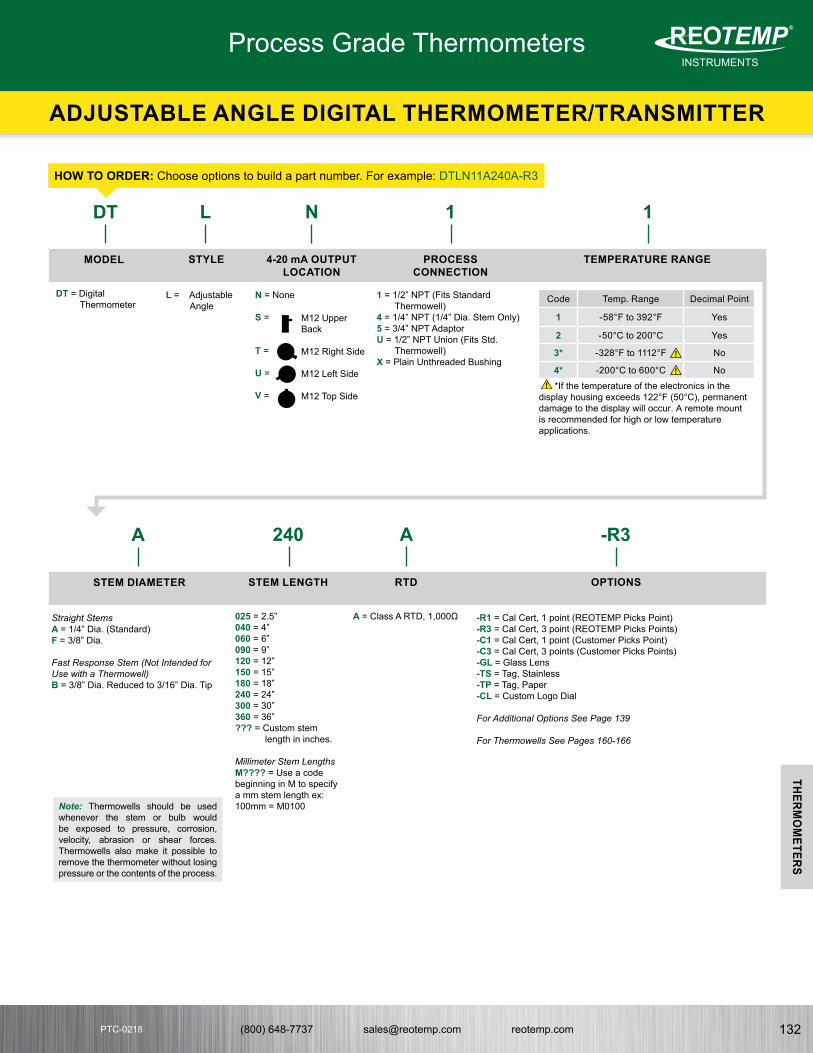
(800) 648-7737 [email protected] reotemp.com 132
INSTRUMENTSMeasuring your world since 1965
®THERM
OM
ETERS
PTC-0218PTC-0218
HOW TO ORDERHOW TO ORDER: Choose options to build a part number. For example: DTLN11A240A-R3
DT L
A
STYLE
L = Adjustable Angle
MODEL
DT = Digital Thermometer
Note: Thermowells should be used whenever the stem or bulb would be exposed to pressure, corrosion, velocity, abrasion or shear forces. Thermowells also make it possible to remove the thermometer without losing pressure or the contents of the process.
240
STEM LENGTH
025 = 2.5”040 = 4” 060 = 6”090 = 9”120 = 12”150 = 15”180 = 18”240 = 24”300 = 30”360 = 36”??? = Custom stem
length in inches.
Millimeter Stem LengthsM???? = Use a code beginning in M to specify a mm stem length ex: 100mm = M0100
A
RTD
A = Class A RTD, 1,000Ω
-R3
OPTIONS
-R1 = Cal Cert, 1 point (REOTEMP Picks Point)-R3 = Cal Cert, 3 point (REOTEMP Picks Points)-C1 = Cal Cert, 1 point (Customer Picks Point)-C3 = Cal Cert, 3 points (Customer Picks Points)-GL = Glass Lens-TS = Tag, Stainless-TP = Tag, Paper-CL = Custom Logo Dial
For Additional Options See Page 139
For Thermowells See Pages 160-166
STEM DIAMETER
Straight StemsA = 1/4” Dia. (Standard)F = 3/8” Dia.
Fast Response Stem (Not Intended for Use with a Thermowell)B = 3/8” Dia. Reduced to 3/16” Dia. Tip
N
4-20 mA OUTPUTLOCATION
N = None
S =
T =
U =
V =
M12 Upper Back
M12 Right Side
M12 Left Side
M12 Top Side
Process Grade Thermometers
ADJUSTABLE ANGLE DIGITAL THERMOMETER/TRANSMITTER
1
PROCESSCONNECTION
1 = 1/2” NPT (Fits Standard Thermowell)
4 = 1/4” NPT (1/4” Dia. Stem Only)5 = 3/4” NPT AdaptorU = 1/2” NPT Union (Fits Std.
Thermowell)X = Plain Unthreaded Bushing
1
TEMPERATURE RANGE
*If the temperature of the electronics in the display housing exceeds 122°F (50°C), permanent damage to the display will occur. A remote mount is recommended for high or low temperature applications.
Code Temp. Range Decimal Point
1 -58°F to 392°F Yes
2 -50°C to 200°C Yes
3* -328°F to 1112°F No
4* -200°C to 600°C No
!
!
!

(800) 648-7737 [email protected] reotemp.com133
INSTRUMENTSMeasuring your world since 1965
®
THERMO
METERS
PTC-0218
• 3-A Conformance Certificate Included• High Accuracy 1,000Ω RTD (Class A)• Water Resistant IP67/NEMA 4X• 5 Year Battery Life• 4-20 mA Output Available• Low or High Temperature Range Models
REOTEMP’s Sanitary Digital Thermometer/Transmitter is a high accuracy thermometer with digital display. It features an IP67/NEMA 4X enclosure, clean-in-place connection, and a 5 year battery life. The Digital Thermometer is perfect for brewing, food, beverage and pharmaceutical applications where a high accuracy digital readout is required.
Accuracy Custom Logo
FEATURES / BENEFITS
SPECIFICATIONS
Made in the USA
Certified
All dimensions are in inches.
All dimensions are in inches.
Accuracy ± ( 0.72 + 0.002 x | t-32 | ) °F,± ( 0.42 + 0.002 x | t | ) °C, where t = temperature. Example: At 32°F accuracy is ± 0.72 °F.
Sensing Element RTD, Type Pt1000Ω, Class A
Temperature Ranges -58°F to 392°F (-50°C to 200°C) or -328°F to 1112°F (-200°C to 600°C)
Output (Optional) 4-20 mA, M12 Connector
Refresh Rate 3 Seconds
Display 4-digit LCD, 1/2” Height
Display Resolution See Table 1
RFI Effect 1% or Less Typical
Temperature Effect 32°F to 122°F (0°C to 50°C)
Storage Temperature Range
-4°F to 158°F (-20°C to 70°C)
Housing Material Stainless Steel 316
Wetted Finish Ra 32 max., Ra 20 max. (optional)
Lens Plastic Polycarbonate (Standard) or Glass
Probe Material 304 Stainless Steel
Weight 12 oz., Varies by Configuration
Environmental Protection
NEMA 4X/IP67
Power 1 x 3.6V AA Battery (M12 is loop powered 9-36 VDC.)
Battery Life 5 Years Minimum in Continuous Mode
Electronic Display Temperature Limit
If the temperature of the electronics in the display housing exceeds 122°F (50°C), permanent damage to the display will occur. A remote mount is recommended for high temperature applications.
DIGITAL SANITARY THERMOMETER
4.6 NOM.
STEM LENGTH
TRI-CLAMP
Ø3.4
STEM LENGTH
TRI-CLAMP
M12, 4-20 mA(OPTIONAL)
M12, 4-20 mA(OPTIONAL)
3.3 NOM.
Ø3.4
DIGITAL SANITARY THERMOMETER
4.6 NOM.
STEM LENGTH
TRI-CLAMP
Ø3.4
STEM LENGTH
TRI-CLAMP
M12, 4-20 mA(OPTIONAL)
M12, 4-20 mA(OPTIONAL)
3.3 NOM.
Ø3.4
M12 Wiring Diagram for 4-20 mA Output Option
Table 1: Display Resolution
Model Range Decimal Point
Low Temp, Displays Decimal
-58°F to 392°F(-50C to 200C ) Yes
High Temp, No Decimal
-328°F to 1112°F(-200°C to 600°C) No
Process Grade Thermometers
SANITARY DIGITAL THERMOMETER/TRANSMITTER

(800) 648-7737 [email protected] reotemp.com 134
INSTRUMENTSMeasuring your world since 1965
®THERM
OM
ETERS
PTC-0218PTC-0218
HOW TO ORDERHOW TO ORDER: Choose options to build a part number. For example: DTXNC1A240A-R3
DT X C
A
STYLE
A = Back Connect
X = Bottom Connect
PROCESSCONNECTION
C = 1.5” Tri-Clamp®
L = 2” Tri-Clamp®
A = 2.5” Tri-Clamp®
P = 3” Tri-Clamp®
M = 3/4” Tri-Clamp®
K = 4” Tri-Clamp®
MODEL
DT = Digital Sanitary Thermometer
Note: Thermowells should be used whenever the stem or bulb would be exposed to pressure, corrosion, velocity, abrasion or shear forces. Thermowells also make it possible to remove the thermometer without losing pressure or the contents of the process.
240
STEM LENGTH
025 = 2.5”040 = 4” 060 = 6”090 = 9”120 = 12”150 = 15”180 = 18”240 = 24”300 = 30”360 = 36”??? = Custom stem
length in inches.
Millimeter Stem LengthsM???? = Use a code beginning in M to specify a mm stem length ex: 100mm = M0100
A
RTD
A = Class A RTD, 1,000Ω
-R3
OPTIONS
-R1 = Cal Cert, 1 point (REOTEMP Picks Point)-R3 = Cal Cert, 3 point (REOTEMP Picks Points)-C1 = Cal Cert, 1 point (Customer Picks Point)-C3 = Cal Cert, 3 points (Customer Picks Points)-GL = Glass Lens-TS = Tag, Stainless-TP = Tag, Paper-CL = Custom Logo Dial
For Additional Options See Page 134
For Thermowells See Pages 160-166
STEM DIAMETER
Straight StemsA = 1/4” Dia. (Standard)F = 3/8” Dia.
Fast Response StemsB = 3/8” Dia. Reduced to 3/16” Dia. Tip
1
TEMPERATURE RANGE
*If the temperature of the electronics in the display housing exceeds 122°F (50°C), permanent damage to the display will occur. A remote mount is recommended for high or low temperature applications.
N
4-20 mA OUTPUTLOCATION
N = None
S =
T =
U =
V =
W =
M12 Upper Back
M12 Right Side
M12 Left Side
M12 Top Side
M12 Bottom Side (Back Connect Style Only)
Code Temp. Range Decimal Point
1 -58°F to 392°F Yes
2 -50°C to 200°C Yes
3* -328°F to 1112°F No
4* -200°C to 600°C No
!
!
!
Process Grade Thermometers
SANITARY DIGITAL THERMOMETER/TRANSMITTER

(800) 648-7737 [email protected] reotemp.com135
INSTRUMENTSMeasuring your world since 1965
®
THERMO
METERS
PTC-0218
Process Grade Thermometers
HANDHELD DIGITAL THERMOMETER
• 3” Dial with Plastic (Polycarbonate) Lens• Easy-to-Read 4 Digit LCD Display with Decimal Point• High Accuracy Class A RTD• Water Resistant IP67/NEMA 4X• Rugged All Stainless Steel Construction• Fast Response Stem
FEATURES / BENEFITS
SPECIFICATIONS
REOTEMP’s Handheld Digital Thermometer is a multi-purpose high accuracy thermometer used to spot check various process media commonly found in the brewing and food & beverage industries. The Digital Handheld Thermometer features rugged all stainless steel construction and a built-in handle for ease of handling and extra protection.
Accuracy Custom Logo Made in the USA
Accuracy ± ( 0.72 + 0.002 x | t-32 | ) °F,± ( 0.42 + 0.002 x | t | ) °C, where t = temperature. Example: At 32°F accuracy is ± 0.72 °F.
Sensing Element RTD, Type Pt1000Ω, Class A
Temperature Ranges -58°F to 392°F (-50°C to 200°C) or -328°F to 1112°F (-200°C to 600°C)
Refresh Rate 3 Seconds
Display 4-digit LCD, 1/2” Height
Display Resolution See Table 1
RFI Effect 1% or Less Typical
Temperature Effect 32°F to 122°F (0°C to 50°C)
Storage Temperature Range
-4°F to 158°F (-20°C to 70°C)
Housing Material Stainless Steel 316
Lens Plastic Polycarbonate (Standard) or Glass
Probe Material 304 Stainless Steel
Weight 12 oz., Varies by Configuration
Environmental Protection
NEMA 4X/IP67
Power 1 x 3.6V AA Battery (M12 is loop powered 9-36 VDC.)
Battery Life 5 Years Minimum in Continuous Mode
Electronic Display Temperature Limit
If the temperature of the electronics in the display housing exceeds 122°F (50°C), permanent damage to the display will occur. A remote mount is recommended for high temperature applications.
Table 1: Display Resolution
Model Range Decimal Point
Low Temp, Displays Decimal
-58°F to 392°F(-50C to 200C ) Yes
High Temp, No Decimal
-328°F to 1112°F(-200°C to 600°C) No

(800) 648-7737 [email protected] reotemp.com 136
INSTRUMENTSMeasuring your world since 1965
®THERM
OM
ETERS
PTC-0218PTC-0218
All dimensions are in inches.
1
1
2
2
3
3
4
4
A A
B B
C C
D D
STEM LENGTH
Ø3/16
1.25
Ø3/8
Ø3.4 Ø5.1
HOW TO ORDERHOW TO ORDER: Choose options to build a part number. For example: BTA11B360A
360
B
A
STEMDIAMETER
B = 3/8” Stem with Fast Response 3/16” Tip
BT
MODEL
BT = Digital Handheld Thermometer with Bezel Head and Stainless Handle
A
STYLE
A = Back Connect
1
CONNECTION
1 = 1/2” NPT
1
TEMPRANGE
OPTIONS
-CL = Custom Logo Dial-R1 = Cal Cert, 1 point (REOTEMP Picks Point)-R3 = Cal Cert, 3 point (REOTEMP Picks Points)-C1 = Cal Cert, 1 point (Customer Picks Point)-C3 = Cal Cert, 3 points (Customer Picks Points)-GL = Glass Lens-TS = Tag, Stainless-TP = Tag, Paper
For Additional Options See Page 139
STEMLENGTH
120 = 12” Stem240 = 24” Stem360 = 36” Stem480 = 48” Stem600 = 60” Stem720 = 72” Stem840 = 84” Stem960 = 96” Stem??? = Custom
stem length in inches.
Millimeter Stem LengthsM???? = Use a code beginning in M to specify a mm stem length ex: 100mm = M0100
RTD
A = Class A 1000Ω RTD
Process Grade Thermometers
HANDHELD DIGITAL THERMOMETER
Code Temp. Range Decimal Point
1 -58°F to 392°F Yes
2 -50°C to 200°C Yes
3 -328°F to 1112°F No
4 -200°C to 600°C No

(800) 648-7737 [email protected] reotemp.com137
INSTRUMENTSMeasuring your world since 1965
®
THERMO
METERS
PTC-0218
• Made to ASME B40.3 Specifications • Accuracy ± 1% Full Scale. (ASME B40.3) • Standard External Reset • One Year Warranty • Made in the USA• All-Stainless Steel Construction
REOTEMP’s OEM Thermometers are the perfect choice for equipment with limited space that requires a rugged, dependable, and economical temperature sensor. These thermometers are also available with a wide variety of mounting threads.
Accuracy
1%
Custom Logo
FEATURES / BENEFITS
B40.3
SPECIFICATIONS
Made in the USA
Model H - 2-3/8” (2.38)
Model Q - 1-5/32” (1.16)
Model G - 1-11/16” (1.68)
P18 - SMALL DIAL BIMETAL THERMOMETERS
∅2.4
.4
.2
STEM LENGTH
∅1/4
STEM LENGTH
∅1.7
∅.3
.3
.2.2
∅1/4
STEM LENGTH
∅1.2
∅.3
.3
.2.2
∅1/4
P18 - SMALL DIAL BIMETAL THERMOMETERS
∅2.4
.4
.2
STEM LENGTH
∅1/4
STEM LENGTH
∅1.7
∅.3
.3
.2.2
∅1/4
STEM LENGTH
∅1.2
∅.3
.3
.2.2
∅1/4
P18 - SMALL DIAL BIMETAL THERMOMETERS
∅2.4
.4
.2
STEM LENGTH
∅1/4
STEM LENGTH
∅1.7
∅.3
.3
.2.2
∅1/4
STEM LENGTH
∅1.2
∅.3
.3
.2.2
∅1/4
All dimensions are in inches.
All dimensions are in inches.
All dimensions are in inches.
Accuracy ± 1% Full Scale (ASME B40.3)
Dial Size 1-5/32” (1.16), 1-11/16” (1.68), 2-3/8” (2.38)
Dial Material Black marks on satin matte aluminum finish, or White Dial
Stem Length 2” to 80”
Stem Diameter 1/4” or 5/16”
Head, Bezel, Mounting Bushing, Stems
300 Series SS, 316SS (Optional)
Operating Conditions Head temperature should not exceed 200°F. Stem should not be exposed to continuous temperatures exceeding 50% over-range or 800°F.
Environmental Protection
IP67, NEMA 6 Rated
Lens Glass (Standard), Acrylic, or Polycarbonate
Immersion Minimum 2” in liquid, and 4” in gas for most ranges. Certain ranges require up to 4” in liquids & 5” in gas.
Mounting Connection Plain Bushing (standard), 1/2” NPT, 3/8”-24 NF (straight threaded), 1/4” NPT, 1/8” NPT, 3/8” NPT, Hex Reset Bushing
Temperature Sensing Area
Last 2” to 4” of the stem
Process Grade Thermometers
SMALL DIAL BIMETAL THERMOMETERS

(800) 648-7737 [email protected] reotemp.com 138
INSTRUMENTSMeasuring your world since 1965
®THERM
OM
ETERS
PTC-0218PTC-0218
HOW TO ORDERHOW TO ORDER: Choose options to build a part number. For example: QQ0251F23-PS
QQ 025 2 F23 -PS
STEM LENGTH
025 = 2.5”040 = 4” 060 = 6”090 = 9”120 = 12”150 = 15”180 = 18”240 = 24”300 = 30”360 = 36”
Note: Intermediate stem lengths available up to 80”.
Millimeter Stem LengthsM???? = Use a code beginning in M to specify a mm stem length ex: 100mm = M0100
CONNECTION
2 = Plain Bushing (std)1 = 1/2” NPT3 = 3/8” - 24 NF (straight
threaded)4 = 1/4” NPT6 = 1/8” NPT7 = 3/8” NPT8 = Hex Reset Bushing
TEMPERATURE RANGE OPTIONS
General Options (Choose up to 4)-PS = Pointed Stem -SS = 316 Stainless Stem-CL = Custom Logo Dial
Window Options (Std. is glass)-PC = Acrylic Window
Calibration Cert. Options-R1 = One Point Calibration Cert
(REOTEMP Chooses Points)-R3 = Three Point Calibration Cert
(REOTEMP Chooses Points)
For Additional Options See Page 139
For Thermowells See Pages 160-166
ü Check Stockü Configure Part #
ü Get Priceü Generate a Custom Engineering DrawingVisit reotemp.com
MODELS
OEM ModelsQQ = Model Q
1-5/32” (1.16) Dial
GG = Model G 1-11/16” (1.68)Dial
HH = Model H 2-3/8” (2.38) Dial
Lab & Test ModelsQP = Model QP (1
5/32” Dial) with 5” Stem
GL = Model GL (1 11/16” Dial) with 8” Stem
HL = Model HL (2 3/8” Dial) with 8” Stem
Fahrenheit RangesF23 = -40°F to 160°F F55 = 25°F to 125°F* F43 = 0°F to 200°F F47 = 0°F to 250°F F63 = 50°F to 300°F F67 = 50°F to 500°F F69 = 50°F to 550°F F81 = 150°F to 750°F F85 = 200°F to 1000°F
Celsius RangesC23 = -40°C to 70°C C55 = 0°C to 50°C*C43 = 0°C to 100°C C4 = -20°C to 120°C C59 = 0°C to 150°C C67 = 0°C to 250°C C69 = 0°C to 300°C C73 = 0°C to 400°C C85 = 100°C to 500°C
Dual Scale RangesD23 = -40°F to 160°F & -40°C to 70°CD55 = 25°F to 125°F & -5°C to 50°C*D43 = 0°F to 200°F & -10°C to 90°CD47 = 0°F to 250°F & -20°C to 120°CD63 = 50°F to 300°F & 10°C to 150°CD67 = 50°F to 500°F & 10°C to 260°CD69 = 50°F to 550°F & 10°C to 290°CD81 = 150°F to 750°F & 70°C to 400°CD85 = 200°F to 1000°F & 100°C to 500°C
*Not available in 2.5” stem.
For Additional Ranges See Master Range Code Sheet on Page 141
Note: Thermowells should be used whenever the stem or bulb would be exposed to pressure, corrosion, velocity, abrasion or shear forces. Thermowells also make it possible to remove the thermometer without losing pressure or the contents of the process.
Lab Model QP with 1.2” Dial(with point - Model QPP)
Lab Model GL with 1.7” Dial(with point - Model QLP)
Lab Model HL with 2.4” Dial(with point - Model HLP)
REOTEMP’s Laboratory Thermometers (QP, GL & HL) are ideal for testing and spot checking local temperatures in a variety of critical process or lab applications. Pointed stems are available for insertion in semi-solids such as soil, meat, etc.
P.24 HAND-HELD LABORATORY THERMOMETER
8Stem
�Ø1.7
.3
.2
� 1/49/16 HEXRESET BUSHING
�Ø2.4
.4
.2
8Stem
� 1/49/16 HEXRESET BUSHING
5Stem
�Ø1.2
.3
.2
� 1/49/16 HEXRESET BUSHING
P.24 HAND-HELD LABORATORY THERMOMETER
8Stem
�Ø1.7
.3
.2
� 1/49/16 HEXRESET BUSHING
�Ø2.4
.4
.2
8Stem
� 1/49/16 HEXRESET BUSHING
5Stem
�Ø1.2
.3
.2
� 1/49/16 HEXRESET BUSHING
P.24 HAND-HELD LABORATORY THERMOMETER
8Stem
�Ø1.7
.3
.2
� 1/49/16 HEXRESET BUSHING
�Ø2.4
.4
.2
8Stem
� 1/49/16 HEXRESET BUSHING
5Stem
�Ø1.2
.3
.2
� 1/49/16 HEXRESET BUSHING
All dimensions are in inches. All dimensions are in inches. All dimensions are in inches.
Process Grade Thermometers
SMALL DIAL BIMETAL THERMOMETERS

(800) 648-7737 [email protected] reotemp.com139
INSTRUMENTSMeasuring your world since 1965
®
THERMO
METERS
PTC-0218
Industrial Small Dial OEM Digital Dual Mode
Thermometer
Part # Description
AA, RR, CC, CN, BB, SS, XR, XX, YY, YN, VR, VV,
LL, MM, JJ
QQ, GG, HHDT,
DTR, BT
DMT
CASE FILL OPTIONS
-SF Silicone Filled Case ü N/A N/A ü
LENS OPTIONS
-PC Acrylic Window ü ü N/A ü
-PY Polycarbonate Window ü ü STD ü
-TG Tempered Safety Glass Lens ü N/A N/A ü
-SG Laminated Safety Glass Lens ü N/A N/A ü
-GL Plain Glass STD STD ü STD
STEM OPTIONS
-PS Pointed Tip ü ü ü N/A
-SS 316 Stainless Steel Stem ü ü ü ü
-F5 5/16” Diameter Stem (Not Available with 316SS Stem) ü ü ü N/A
-S3 3/8” Diameter Stem ü ü ü ü
-TF Teflon Coating (Stem Only) ü ü ü ü
DIAL OPTIONS
-CL Custom Logo Dial ü ü ü ü
-HV Hi-Vis Dial ü MQ N/A ü
-CB Color Band ü MQ N/A ü
-CP Color Pie ü MQ N/A ü
-WD White Dial (Standard Ranges Only) ü ü ü ü
-MM Min/Max Pointer ü N/A N/A ü
NL No Logo ü ü ü ü
TAG OPTION
-TS Stainless Steel Tag (1-10 Characters) ü ü ü ü
-TP Paper Tag ü ü ü ü
CERTIFICATION OPTIONS
-R1 1pt. Calibration Certification (REOTEMP Chooses the Point) ü ü ü ü
-R3 3 pt. Calibration Certification (REOTEMP Chooses the Points) ü ü ü ü
-C1 1 pt. Calibration Certification (Customer Chooses the Point) ü ü ü ü
-C3 3 pt. Calibration Certification (Customer Chooses the Points) ü ü ü ü
-CS NIST Calibration Sticker (No Logged Points) ü ü ü ü
-CC Certificate of Conformance ü ü ü ü
OTHER
-3H 316 Stainless Steel Head & Bezel ü N/A STD ü
-HT Heat Transfer Compound ü ü ü ü
-CH Spring Handle (T-27) ü ü ü N/A
-AS Allows Bimet to Fit 1-1/4-18 Industrial Thermowell ü ü ü ü
-EH Explosion Proof Head N/A N/A ü ü
ü Indicates that the option is available with the model.
STD Indicates standard options with no additional cost.
N/A Indicates the option is not available with this model.
MQ Minimum order quantity applies.
DIAL INDICATING THERMOMETER OPTIONS
Customization

(800) 648-7737 [email protected] reotemp.com 140
INSTRUMENTSMeasuring your world since 1965
®THERM
OM
ETERS
PTC-0218PTC-0218
BIMETAL OPTIONS
Customization
REOTEMP’s Hi-Vis™ dial increases the visibility of dials in low-light environments and from a
distance. Hi-Vis™ dials are often used in areas where readings are paramount to safety. They can also be used to differentiate between two different process lines within a facility.
Color bands and pies highlight a specific range on the gauge so that it is immediately apparent if the process falls within a critical temperature range.
Thermometer dials offer a unique opportunity to communicate critical information, highlight installation specifications, or promote an OEM or end-user brand.
COLOR BANDS & COLOR PIES
CUSTOM LOGO DIAL
ü In-depth Videos on our Customization Optionsü Product Demonstration VideosVisit reotemp.com/youtube
Color BandColor Pie
-HV Hi-Vis™ High Visibility DialAvailability Process Grade Thermometers
-CB Color Band (Specify Colors and Ranges)
-CP Color Pie (Specify Colors and Ranges)Availability Process Grade Thermometers
-DM Dial Marking
Availability All Dial Indicating Thermometers.
-CL Custom Logo DialAvailability All Dial Indicating Thermometers.
Add text, a serial number, tag number, equipment class, or other text to the thermometer dial face.
DIAL MARKING
Hi VisTM
Custom Logo
Min-Max Pointer with Color Bands
Hi-Vis™

(800) 648-7737 [email protected] reotemp.com141
INSTRUMENTSMeasuring your world since 1965
®
THERMO
METERS
PTC-0218
FAHRENHEIT RANGESCode °F Range Div.
F03 -100/100 2
F05 -100/200 2
F07 -80/120 2
F11 -70/150 2
F19 -50/300 5
F21† -40/120 2
F23 -40/160 2
F25 -40/180 2
F26 -40/200 2
F27‡ -40/70 1
F31† -20/120 2
F33 -20/425 5
F35‡ 0/100 1
F37† 0/140 2
F39† 0/150 1
F43 0/200 2
F45 0/220 2
F47 0/250 2
F49 0/300 2
F50 0/500 5
F51 0/600 10
F53 20/240 2
F55‡ 25/125 1
F57‡ 30/130 1
F63 50/300 2
F65 50/400 5
F67 50/500 5
F69 50/550 5
F71 50/650 10
F73 50/750 10
F78 100/600 5
F79 100/800 10
F81 150/750 10
F82 200/700 20
F83 200/300 2
F84 100/900 5
F85 200/1000 10
F89 250/600 5
F91 300/400 2
F92 0/1200 2
‡ Minimum stem length is 4”.† For 2.5” stem, all bottom connect and all-angle models require adapter P/N AD22S.
CELSIUS RANGESCode °C Range Div.
C01 -80/220 2
C03 -70/70 2
C06 -70/30 1
C07 -50/50 1
C08 -60/120 2
C09‡ -50/0 1
C15 -50/100 2
C17 -50/200 2
C19 -40/160 2
C20 -60/300 5
C23 -40/70 1
C24 -40/350 5
C27‡ -30/30 1
C31‡ -20/40 1
C32 -20/60
C33 -20/220 2
C34 -20/320 5
C35‡ 0/30 .5
C37‡ 0/60 1
C38† 0/80
C43 0/100 1
C47 -20/200 2
C53 -10/110 1
C55‡ 0/50 .5
C56 0/120 1
C59 0/150 1
C60 50/150
C61 0/160 2
C63 10/150 2
C65 0/200 2
C67 0/250 2
C69 0/300 2
C71 0/300 5
C73 0/400 5
C74 0/450 5
C75 0/500 5
C79 50/450 5
C81 50/400 5
C85 100/500 5
C87 100/550 5
DUAL RANGESCode °F & °C Range
D01 -150/400 & 100/200
D03 -100/100 & -70/40
D07 -80/120 & -60/50
D15 -50/210 & -50/100
D19 -50/300 & -40/160
D23 -40/160 & -40/70
D37† 0/140 & -15/60
D39† 0/150 & -20/65
D41† 0/160 & -15/70
D43 0/200 & -10/90
D45 0/220 & -10/100
D47 0/250 & -20/120
D49 0/300 & -10/150
D53 20/240 & -10/115
D55‡ 25/125 & -5/50
D63 50/300 & 10/150
D65 50/400 & 10/200
D67 50/500 & 10/260
D69 50/550 & 10/290
D77 100/450 & 40/230
D79 100/800 & 40/400
D81 150/750 & 70/400
D85 200/1000 & 100/500
D87 200/1000 & 100/550
BIMETAL TEMPERATURE RANGE CODE MASTER LIST

(800) 648-7737 [email protected] reotemp.com 142
INSTRUMENTSMeasuring your world since 1965
®THERM
OM
ETERS
PTC-0218PTC-0218
• Accurate and Rugged• Quick Response• Shock Resistant• Sensitive Bimetal Element• External Reset Adjustment• Waterproof and Dust Proof• Stainless Steel or Plastic Pocket Case
SPECIFICATIONSThe REOTEMP Surface Bimetal Thermometer measures temperature on any horizontal surface. The magnetic feet on this model snap it securely to any ferrous surface. It is commonly used on griddles, ovens, motors, piping and tanks.
SPECIFICATIONS
K-79 Analog Dial Model
HOW TO ORDER
SUR-15TEMPERATURERANGE
SUR-15 = 0 to 150°F & -20 to 65°CSUR-25 = 0 to 250°F & -20 to 120°CSUR-50 = 0 to 500°F & -20 to 260°CSUR-75 = 50 to 750°F & 10 to 400°C
HOW TO ORDER
K-79-2TEMPERATURERANGE
Fahrenheit RangesK-79-2 = -40°F to 160°FK-79-3 = 0°F to 220°FK-79-4 = 25°F to 125°FK-79-5 = 50°F to 550°F
Celsius RangesK-79-7 = -10°C to 110°CK-79-8 = 0°C to 150°CK-79-9 = 0°C to 250°C
FEATURES / BENEFITS
Front View
Back View
Protective Coverand Heat CollectorMagnets
Bimetal SensingElement
Accuracy ± 2% Full Scale
Sensing Element Precision Calibrated Bimetal Coil
Dial Size 2” (5.08cm)
Dial Material Aluminum background with black marks.
Case Aluminum
Lens Glass
Height 1/2” (1.27cm)
Weight Approximately 2 ounces (56.7g)
Response Time Approximately 1 minute.
Mounting Two magnets on back.
Accuracy ± 2% Full Scale
Dial Size 1” Diameter (25mm)
Dial Material White background with crisp letters, marks, and numbers.
Stem Length 142 O.D., 5” long, pointed (36mm x 127mm)
Pocket Case Plastic with clip and holder loop.
Lens Glass
Reset Nut 7/16 Hex (11mm)
Weight 0.65 Ounces (18.5g)
Packed 1 per box, 12 per carton
POCKET BIMETAL THERMOMETER
SURFACE THERMOMETER
OEM Thermometers

(800) 648-7737 [email protected] reotemp.com143
INSTRUMENTSMeasuring your world since 1965
®
THERMO
METERS
PTC-0218
• All-Stainless Construction • Hermetically Sealed• Standard External Reset for Easy Calibration• One Year Warranty
REOTEMP’s O-TEMP Bimetal Thermometers are reliable and accurate temperature sensors requiring no electricity or wiring. The O-TEMP line is designed for OEM applications in a variety of industrial applications where a more economical option is needed. They can be recalibrated with a turn of the calibration screw on the back of the dial. A variety of options are available for your specific process needs.
FEATURES / BENEFITS
SPECIFICATIONSTEMP- TM
Quality OEM Thermometers from REOTEMP Instruments
Model Dial Size Connection A
AO 3” 1/2” NPT 3.3”
CO 4” 1/2” NPT 4.3”
BO 5” 1/2” NPT 5.3”
All dimensions are in inches.
Accuracy Back and Adjustable: ± 1.5% Full ScaleBottom: ± 2% Full Scale
Dial Size 3”, 4” or 5”
Dial Material White background with black marks.
Stem Length 2” to 36”
Stem Diameter 1/4”
Head, Bezel, Mounting Bushing, Stems
304SS
Operating Conditions Head temperature should not exceed 200°F. Stem should not be exposed to continuous temperatures exceeding 50% over-range or 800°F.
Environmental Protection
IP65, Hermetically Sealed
Lens Glass (Standard), Acrylic, Polycarbonate, Tempered Glass, or Laminated Safety Glass
Immersion Minimum 2” in liquid, and 4” in gas for most ranges. Certain ranges require up to 4” in liquids & 5” in gas.
Mounting Connection 1/2” NPT (Standard), 1/4” NPT, or 1/2” BSPT
Temperature Sensing Area
Last 2” to 4” of the stem
Model Dial Size Connection A
LO 3” 1/2” NPT 3.3”
MO 4” 1/2” NPT 4.3”
JO 5” 1/2” NPT 5.3”
Model Dial Size Connection A
XO 3” 1/2” NPT 3.3”
YO 4” 1/2” NPT 4.3”
VO 5” 1/2” NPT 5.3”
All dimensions are in inches.
P26 - BACK CONNECT BIMETAL THERMOMETER
STEM LENGTH .4 1
A
NOTE - DWG IS ACTUAL SIZE FOR FUTURE USE
RESET
P28 - ADJUSTABLE ANGLE BIMETAL THERMOMETER
A
STEMLENGTH
3.9
1
RESET
P.30 - BOTTOM CONNECT BIMETAL THERMOMETER
A
1
1.4.4
STEMLENGTH
RESET
BIMETAL THERMOMETERS
OEM Thermometers
TEMP- TM

(800) 648-7737 [email protected] reotemp.com 144
INSTRUMENTSMeasuring your world since 1965
®THERM
OM
ETERS
PTC-0218PTC-0218
HOW TO ORDERHOW TO ORDER: Choose options to build a part number. For example: AO0251F23
AO 025 1 F23
DIAL SIZE& STYLE
Back ConnectAO = 3” Dial w/ ResetCO = 4” Dial w/ ResetBO = 5” Dial w/ Reset
Adjustable AngleLO = 3” Dial w/ ResetMO = 4” Dial w/ ResetJO= 5” Dial w/ Reset
Bottom ConnectXO = 3” Dial w/ ResetYO = 4” Dial w/ ResetVO = 5” Dial w/ Reset
STEM LENGTH
025 = 2.5”040 = 4” 060 = 6”090 = 9”120 = 12”150 = 15”180 = 18”240 = 24”300 = 30”360 = 36”
Note: Intermediate stem lengths available up to 80”.
CONNECTION
1 = 1/2” NPT4 = 1/4” NPTB = 1/2” BSPT
TEMPERATURE RANGE
Fahrenheit RangesF23 = -40°F to 160°F F47 = 0°F to 250°F F69 = 50°F to 550°F
Celsius RangesC43 = 0°C to 100°C C69 = 0°C to 300°C
For Additional Custom Ranges See Master Range Code Sheet on 141
Note: Thermowells should be used whenever the stem or bulb would be exposed to pressure, corrosion, velocity, abrasion or shear forces. Thermowells also make it possible to remove the thermometer without losing pressure or the contents of the process.
MODELS TYPICALLY IN STOCK
3" Dial, Back Connect, 1/2" NPT
0/250°F 50/550°F
2.5" Stem AO0251F47 AO0251F69
4" Stem AO0401F47 AO0401F69
6" Stem AO0601F47 AO0601F69
9" Stem AO0901F47 AO0901F69
12" Stem AO1201F47
5" Dial, Adjustable Angle, 1/2" NPT
0/250°F 50/550°F
2.5" Stem JO0251F47 JO0251F69
4" Stem JO0401F47 JO0401F69
6" Stem JO0601F47 JO0601F69
9" Stem JO0901F47 JO0901F69
CUSTOM ORDER (MINIMUM QUANTITIES MAY APPLY)
OEM Thermometers
BIMETAL THERMOMETERSTEMP- TM

(800) 648-7737 [email protected] reotemp.com145
INSTRUMENTSMeasuring your world since 1965
®
THERMO
METERS
PTC-0218
• High Accuracy 1,000Ω RTD (Class A)• Water Resistant IP67/NEMA 4X• 5 Year Battery Life• 4-20 mA Output Available• Low or High Temperature Range Models
REOTEMP’s Remote Digital Thermometer/Transmitter is a high accuracy thermometer with digital display. It features an IP67/NEMA 4X enclosure and a 5 year battery life. The Remote Digital is perfect for a variety of markets and applications where a high accuracy digital readout is required.
Accuracy Custom Logo
FEATURES / BENEFITS
SPECIFICATIONS
Made in the USA
Accuracy ± ( 0.72 + 0.002 x | t-32 | ) °F,± ( 0.42 + 0.002 x | t | ) °C, where t = temperature. Example: At 32°F accuracy is ± 0.72 °F.
Sensing Element RTD, Type Pt1000Ω, Class A
Temperature Ranges -58°F to 392°F (-50°C to 200°C) or -328°F to 1112°F (-200°C to 600°C)
Output (Optional) 4-20 mA, M12 Connector
Refresh Rate 3 Seconds
Display 4-digit LCD, 1/2” Height
Display Resolution See Table 1
RFI Effect 1% or Less Typical
Ambient Temperature Range
32°F to 122°F (0°C to 50°C)
Housing Material Stainless Steel 316
Lens Plastic Polycarbonate (Standard) or Glass
Probe Material 304 Stainless Steel
Weight 12 oz., Varies by Configuration
Environmental Protection
NEMA 4X/IP67
Power 1 x 3.6V AA Battery (M12 is loop powered 9-36 VDC.)
Battery Life 5 Years Minimum in Continuous Mode
Electronic Display Temperature Limit
If the temperature of the electronics in the display housing exceeds 122°F (50°C), permanent damage to the display will occur. A remote mount is recommended for high or low temperature applications.
Table 1: Display Resolution
Model Range Decimal Point
Low Temp, Displays Decimal
-58°F to 392°F(-50C to 200C ) Yes
High Temp, No Decimal
-328°F to 1112°F(-200°C to 600°C) No
All dimensions are in inches.
REMOTE MOUNT DIGITAL THERMOMETER
�Ø3.4
2.9 NOM.
M12, 4-20 mA(OPTIONAL)
FLANGE
M12, 4-20 mA(OPTIONAL)
"B"
STEM LENGTH
"B" 2.4 NOM.
STEM LENGTH
4 NOM.M12, 4-20 mA(OPTIONAL)
2.1 NOM.
�Ø3.0
�Ø3.0
2.4 NOM.
Ø3.4
REMOTE MOUNT DIGITAL THERMOMETER
�Ø3.4
2.9 NOM.
M12, 4-20 mA(OPTIONAL)
FLANGE
M12, 4-20 mA(OPTIONAL)
"B"
STEM LENGTH
"B" 2.4 NOM.
STEM LENGTH
4 NOM.M12, 4-20 mA(OPTIONAL)
2.1 NOM.
�Ø3.0
�Ø3.0
2.4 NOM.
Ø3.4
All dimensions are in inches.
M12 Wiring Diagram for 4-20 mA Output Option
Remote Reading Thermometers
REMOTE DIGITAL THERMOMETER/TRANSMITTER

(800) 648-7737 [email protected] reotemp.com 146
INSTRUMENTSMeasuring your world since 1965
®THERM
OM
ETERS
PTC-0218PTC-0218
HOW TO ORDERHOW TO ORDER: Choose options to build a part number. For example: DTRBXTA01013A240A-R3
DTR
MODEL
DTR = Digital Remote Reading Thermometer
Note: Thermowells should be used whenever the stem or bulb would be exposed to pressure, corrosion, velocity, abrasion or shear forces. Thermowells also make it possible to remove the thermometer without losing pressure or the contents of the process.
X 1
CAPILLARY LOCATION
A = Lower Back Connect
X = Bottom Connect
PROCESSCONNECTION
1 = 1/2” NPT Sliding Compression Fitting (Fits Standard Thermowell)
4 = 1/4” NPT Sliding Compression Fitting (1/4” or 1/8” Dia. Stem)
8 = 1/8” NPT Sliding Compression Fitting (1/8” Dia. Stem Only)
5 = 3/4” NPT AdaptorU = 1/2” NPT Union (Fits
Std. Thermowell)X = Plain Unthreaded
Bushing
240
STEM LENGTH
025 = 2.5”040 = 4” 060 = 6”090 = 9”120 = 12”150 = 15”180 = 18”240 = 24”300 = 30”360 = 36”??? = Custom
stem length in inches.
Millimeter Stem LengthsM???? = Use a code beginning in M to specify a mm stem length ex: 100mm = M0100
A
RTD
A = Class A RTD, 1,000Ω
-R3
OPTIONS
-R1 = Cal Cert, 1 point (REOTEMP Picks Point)-R3 = Cal Cert, 3 point (REOTEMP Picks
Points)-C1 = Cal Cert, 1 point (Customer Picks Point)-C3 = Cal Cert, 3 points (Customer Picks
Points)-GL = Glass Lens-TS = Tag, Stainless-TP = Tag, Paper-EH = Explosion Proof Head FM, CSA, ATEX,
& IECEx Approved, Bottom Connection Only
-CL = Custom Logo Dial
For Additional Options See Page 139
For Thermowells See Pages 160-166
B
MOUNTING
B = Back Flange
F = Front Flange
M = Rear Mounting Bracket
A
CAPILLARYTYPE
A = Stainless Steel Armor
V = Stainless Steel Overbraid
P = Stainless Steel Armor with PVC Coating
T = Stainless Steel Armor With Teflon Coating
010
CAPILLARY LENGTH “B”
??? = Enter Length in Feet. Example: 010 = 10 feet of Capillary.
A
STEM DIAMETER
Straight StemsA = 1/4” Dia. (Standard)F = 3/8” Dia.C = 1/8” Dia.
Fast Response Stem (Not Intended for Use with a Thermowell)B = 3/8” Dia. Reduced to
3/16” Dia. Tip
T
4-20 mA OUTPUTLOCATION
N = None
S =
T =
U =
V =
W =
M12 Upper Back
M12 Right Side
M12 Left Side
M12 Top Side
M12 Bottom Side (Back Connect Style Only)
EH Head Approvals: FM Approved Enclosure Only: CL. I. GR. A,B,C,D; CL. II. GR E,F,G; CL. III.; Type 4X. For CSA Class I, Group A, conduit seal is required within 18 inches. CL. I, ZONE 1, ATEX: d IIC, IP66. ATEX: II 2GD Ex d tD A21 IIC, FTZU 04 ATEX 0265U. IECEx FMG 06.0003U, Ex d II C, IP68.
EH Explosion Proof Head
3
TEMPERATURE RANGE
*If the temperature of the electronics in the display housing exceeds 122°F (50°C), permanent damage to the display will occur. A remote mount is recommended for high or low temperature applications.
Code Temp. Range Decimal Point
1 -58°F to 392°F Yes
2 -50°C to 200°C Yes
3* -328°F to 1112°F No
4* -200°C to 600°C No
!
!
!
1
1
2
2
3
3
4
4
A A
B B
C C
D D
� 4.4
.1
� 2.9
� 3.9.5 .2
Flange Drawing
REMOTE DIGITAL THERMOMETER/TRANSMITTER
Remote Reading Thermometers

(800) 648-7737 [email protected] reotemp.com147
INSTRUMENTSMeasuring your world since 1965
®
THERMO
METERS
PTC-0218
• 3-A Conformance Certificate Included• High Accuracy 1,000Ω RTD (Class A)• Water Resistant IP67/NEMA 4X• 5 Year Battery Life• 4-20 mA Output Available• Low or High Temperature Range Models
REOTEMP’s Sanitary Remote Digital Thermometer/Transmitter is a high accuracy thermometer with digital display. It features an IP67/NEMA 4X enclosure, clean-in-place connection, and a 5 year battery life. The Digital Thermometer is perfect for brewing, food, beverage and pharmaceutical applications where a high accuracy digital readout is required.
Accuracy Custom Logo
FEATURES / BENEFITS
SPECIFICATIONS
Made in the USA
All dimensions are in inches.
Certified
Accuracy ± ( 0.72 + 0.002 x | t-32 | ) °F,± ( 0.42 + 0.002 x | t | ) °C, where t = temperature. Example: At 32°F accuracy is ± 0.72 °F.
Sensing Element RTD, Type Pt1000Ω, Class A
Temperature Ranges -58°F to 392°F (-50°C to 200°C) or -328°F to 1112°F (-200°C to 600°C)
Output (Optional) 4-20 mA, M12 Connector
Refresh Rate 3 Seconds
Display 4-digit LCD, 1/2” Height
Display Resolution See Table 1
RFI Effect 1% or Less Typical
Temperature Effect 32°F to 122°F (0°C to 50°C)
Storage Temperature Range
-4°F to 158°F (-20°C to 70°C)
Housing Material Stainless Steel 316
Lens Plastic Polycarbonate (Standard) or Glass
Probe Material 304 Stainless Steel
Weight 12 oz., Varies by Configuration
Environmental Protection
NEMA 4X/IP67
Power 1 x 3.6V AA Battery (M12 is loop powered 9-36 VDC.)
Battery Life 5 Years Minimum in Continuous Mode
Electronic Display Temperature Limit
If the temperature of the electronics in the display housing exceeds 122°F (50°C), permanent damage to the display will occur. A remote mount is recommended for high temperature applications.
All dimensions are in inches.
M12 Wiring Diagram for 4-20 mA Output Option
SANITARY REMOTE MOUNT DIGITAL THERMOMETER
Ø3.4
2.9 NOM.
M12, 4-20 mA(OPTIONAL)
FLANGE
M12, 4-20 mA(OPTIONAL)
"B"
1 NOM.
STEM LENGTH
"B" 1 NOM.
STEM LENGTH
4 NOM.
TRI-CLAMP
TRI-CLAMP
Ø3.4
M12, 4-20 mA(OPTIONAL)
2.1 NOM.
Ø3.0
Ø3.0
SANITARY REMOTE MOUNT DIGITAL THERMOMETER
Ø3.4
2.9 NOM.
M12, 4-20 mA(OPTIONAL)
FLANGE
M12, 4-20 mA(OPTIONAL)
"B"
1 NOM.
STEM LENGTH
"B" 1 NOM.
STEM LENGTH
4 NOM.
TRI-CLAMP
TRI-CLAMP
Ø3.4
M12, 4-20 mA(OPTIONAL)
2.1 NOM.
Ø3.0
Ø3.0
Table 1: Display Resolution
Model Range Decimal Point
Low Temp, Displays Decimal
-58°F to 392°F(-50C to 200C ) Yes
High Temp, No Decimal
-328°F to 1112°F(-200°C to 600°C) No
SANITARY REMOTE DIGITAL THERMOMETER/TRANSMITTER
Remote Reading Thermometers

(800) 648-7737 [email protected] reotemp.com 148
INSTRUMENTSMeasuring your world since 1965
®THERM
OM
ETERS
PTC-0218PTC-0218
HOW TO ORDERHOW TO ORDER: Choose options to build a part number. For example: DTRBXTA010C1A240A-R3
DTR
MODEL
DTR = Digital Remote Reading Thermometer
Note: Thermowells should be used whenever the stem or bulb would be exposed to pressure, corrosion, velocity, abrasion or shear forces. Thermowells also make it possible to remove the thermometer without losing pressure or the contents of the process.
X C
CAPILLARY LOCATION
A = Lower Back Connect
X = Bottom Connect
PROCESSCONNECTION
C = 1.5” Tri-Clamp®
L = 2” Tri-Clamp®
A = 2.5” Tri-Clamp®
P = 3” Tri-Clamp®
M = 3/4” Tri-Clamp®
K = 4” Tri-Clamp®
240
STEM LENGTH
025 = 2.5”040 = 4” 060 = 6”090 = 9”120 = 12”150 = 15”180 = 18”240 = 24”300 = 30”360 = 36”??? = Custom
stem length in inches.
Millimeter Stem LengthsM???? = Use a code beginning in M to specify a mm stem length ex: 100mm = M0100
A
RTD
A = Class A RTD, 1,000Ω
-R3
OPTIONS
-R1 = Cal Cert, 1 point (REOTEMP Picks Point)-R3 = Cal Cert, 3 point (REOTEMP Picks
Points)-C1 = Cal Cert, 1 point (Customer Picks Point)-C3 = Cal Cert, 3 points (Customer Picks
Points)-GL = Glass Lens-TS = Tag, Stainless-TP = Tag, Paper-CL = Custom Logo Dial
For Additional Options See Page 139
For Thermowells See Pages 160-166
B
MOUNTING
B = Back Flange
F = Front Flange
M = Rear Mounting Bracket
A
CAPILLARYTYPE
A = Stainless Steel Armor
V = Stainless Steel Overbraid
P = Stainless Steel Armor with PVC Coating
T = Stainless Steel Armor With Teflon Coating
010
CAPILLARY LENGTH “B”
??? = Enter Length in Feet. Example: 010 = 10 feet of Capillary.
1 A
TEMPERATURE RANGE
*If the temperature of the electronics in the display housing exceeds 122°F (50°C), permanent damage to the display will occur. A remote mount is recommended for high or low temperature applications.
STEM DIAMETER
Straight StemsA = 1/4” Dia. (Standard)F = 3/8” Dia.
Fast Response StemsB = 3/8” Dia. Reduced to
3/16” Dia. Tip
T
4-20 mA OUTPUTLOCATION
N = None
S =
T =
U =
V =
W =
M12 Upper Back
M12 Right Side
M12 Left Side
M12 Top Side
M12 Bottom Side (Back Connect Style Only)
1
1
2
2
3
3
4
4
A A
B B
C C
D D
� 4.4
.1
� 2.9
� 3.9.5 .2
Flange Drawing
Code Temp. Range Decimal Point
1 -58°F to 392°F Yes
2 -50°C to 200°C Yes
3* -328°F to 1112°F No
4* -200°C to 600°C No
!
!
!
Remote Reading Thermometers
SANITARY REMOTE DIGITAL THERMOMETER/TRANSMITTER

(800) 648-7737 [email protected] reotemp.com149
INSTRUMENTSMeasuring your world since 1965
®
THERMO
METERS
PTC-0218
• Accuracy ± 1 Scale Division (Upper 2/3 Scale)• Ideal for Remote Reading, such as Panel Installation• Capillary Lengths of 1 to 100 Feet• Stainless Steel Sealed Construction• Variety of Flanged or U-Clamp Mounting Options• Brass and 316SS Thermowells for Vapor-Actuated Bulbs
Available.
REOTEMP’s Vapor Actuated Thermometers can be fitted into a large variety of temperature indicating applications. Manufactured to the highest standards, these instruments are ideal for remote reading. Vapor actuated thermometers, are not subject to indicator error due to ambient temperature variations along the capillary tube system, and will give excellent readings provided the measured temperature is above or below ambient temperature.
Note: Vapor instruments have progressive non-linear graduations, and are best read in the upper 2/3 of the dial range. Many ranges are available between -40°F and +350°F, and care should be exercised to select a range that will locate the operating temperatures within the upper 2/3 of the dial range.
FEATURES / BENEFITS
SPECIFICATIONS
Custom Logo
Note: Thermowells should be used whenever the stem or bulb would be exposed to pressure, corrosion, velocity, abrasion or shear forces. Thermowells also make it possible to remove the thermometer without losing pressure or the contents of the process.
Made in the USA
Accuracy ± 1 Scale Division (Upper 2/3 Scale)
Dial Size 2”, 2 1/2”, 3 1/2”, 4 1/2”
Ranges Over twenty °F and °F/°C ranges available, from -40°F to 350°F. For higher temperature ranges, please call REOTEMP to inquire about gas-actuated vapor thermometers.
Case Material All-Stainless Steel, except: VA45FL (Aluminum) and VA45TB (Phenolic)
Bulbs Stainless Steel or Copper. Bulb O.D. 7/16” (threaded), 3/8” (plain). Bulb lengths vary from 2 1/2” to 9 1/4” depending on capillary length.
Pointer Standard Adjustable
Lens Polycarbonate or Glass
Process Connection Plain Bulb, 1/2” NPT Union, 1/2” NPT sliding union on 12” bendable extension, or thermowell.
Bourdon Tube Phosphor Bronze
Movement Brass with Precision Gearing
Dial Material Aluminum with white finish and black markings. Other colors available upon request.
Capillary Copper, copper with bronze braid armor, stainless steel, stainless steel with stainless steel armor. Available lengths from 1-100ft.
Applications Control panels, chemical processing, pipelines, food processing, OEM applications, ovens, solar heating, refrigeration, etc.
VAPOR ACTUATED THERMOMETER
Remote Reading Thermometers

(800) 648-7737 [email protected] reotemp.com 150
INSTRUMENTSMeasuring your world since 1965
®THERM
OM
ETERS
PTC-0218PTC-0218
Part # Dial Size
Case Material Lens Material Connection
Location
Front Flanged (Panel Mount)
20FR 2” SS Polycarbonate** Rear
25FR 2.5” SS Polycarbonate** Rear
35FR 3.5” SS Polycarbonate** Rear
45FR 4.5” SS Polycarbonate** Rear
45FL 4.5” Black Aluminum Glass* Rear
U-Clamp 20UR 2” SS Polycarbonate** Rear
25UR 2.5” SS Polycarbonate** Rear
35UR 3.5” SS Polycarbonate** Rear
Rear Flanged (Surface Mount)
20RR 2” SS Polycarbonate** Rear
35RR 3.5” SS Polycarbonate** Rear
35RB 3.5” SS Polycarbonate** Bottom
45RR 4.5” SS Polycarbonate** Rear
45RB 4.5” SS Polycarbonate** Bottom
45TB 4.5” Phenolic Glass Bottom
Other Styles 35SB 3.5” SS Polycarbonate** Adjustable Bracket Mount
45SB 4.5” SS Polycarbonate** Adjustable Bracket Mount
35DA 3.5” SS Polycarbonate**
Direct Adjustable
Mount with 3.4” Bulb & 1/2”
NPT
45DA 4.5” SS Polycarbonate**
Direct Adjustable
Mount with 3.4” Bulb & 1/2”
NPT
HOW TO ORDERHOW TO ORDER: Choose options to build a part number. For example: V20FRF23D05L2
20FR 23
CASE STYLE
Fahrenheit Ranges20 = -40°F to 60°F30 = -40°F to 100°F32 = -20°F to 120°F72 = 0°F to 180°F49 = 0°F to 150°F80 = 20°F to 220°F50 = 40°F to 240°F56 = 0°F to 250°F60 = 30°F to 300°F†68 = 100°F to 350°
Dual Scale Ranges21 = -40°F to 60°F & -40°C to 15°C31 = -40°F to 110°F & -40°C to 40°C33 = -20°F to 120°F & -30°C to 50°C73 = 0°F to 180°F & -20°C to 80°C79 = 0°F to 150°F & -15°C to 65°C81 = 20°F to 220°F & 0°C to 105°C51 = 40°F to 240°F & 0°C to 115°C57 = 0°F to 250°F & -20°C to 120°C61 = 30°F to 300°F & 0°C to 150°C†66 = 100°F to 350°F & 40°C to 175°C
†Ranges 350°F and over come with a 316SS capillary ONLY.
05 L2
PROCESS CONNECTIONCAPILLARY LENGTH IN FEET
??? = Capillary Length in Ft. (Standard Length is 5 ft.)
Capillary available in lengths 1-100 ft.
Note: Capillary Lengths over 5 feet affect bulb length see table on page 151.
Need Higher Temperature Ranges? Call REOTEMP customer service to inquire about gas-actuated vapor thermometers.
Code Connection Material
J1 None (Plain Bulb) N/A
J2 Jam Nut Only Brass (For Brass Well)
J3 Jam Nut Only Nickel Plated Brass
K2 1/2” NPT Union Brass
L2 1/2" NPT Union 316SS
M2 1/2” Sliding Union on Bendable Extension
316SS (With 316SS Capilalry ONLY)
??? Thermowell .447 Bore See Chart to Right
Thermowells with .447 Bore for Vapor-actuated Bulbs
(Except M2)
1/2” NPT
Brass
3/4” NPTBrass
1/2” NPT
316SS
3/4” NPT316SS
(Bulb #1) 1-10 ft. Capillary 12B 13B 12S 13S
(Bulb #2) 11-25 ft. Capillary 22B 23B 22S 23S
(Bulb #3) 26-50 ft. Capillary 32B 33B 32S 33S
(Bulb #4) 51-75 ft. Capillary 42B 43B 42S 43S
(Bulb #5) 76-100 ft. Capillary 52B 53B 52S 53S
V
CAPILLARY & BULB MATERIAL
CodeCapillary & Bulb
Capillary Protection
A Tin Plated Copper None
C Copper Bronze Braid
D 316SS None
E 316SS SS Armor
TEMPERATURERANGE
D
*Glass Lens Available, specify “Glass Lens”**Polycarbonate Lens Available, specify “Polycarbonate Lens”For other case styles connection locations, specify model and range only. Example: V45DA-80
RR RB
SB
DA
VAPOR ACTUATED THERMOMETER
Remote Reading Thermometers

(800) 648-7737 [email protected] reotemp.com151
INSTRUMENTSMeasuring your world since 1965
®
THERMO
METERS
PTC-0218
Dial Faces Typical dial are faces shown here. A complete list is shown on page 21. Operating temperatures should be in upper 2/3 of selected range. For temperatures above or below those shown, ask for information on REOTEMP Gas Actuated Thermometers.
Bendable ExtensionUnion ConnectionPlain Bulb Thermowell
STANDARD BULB DIMENSIONS
Plain Bulb Union Connection Bendable Extension (Fits .385 Bore) Thermowell
Capillary Length L D U S D L S D U S D
(Bulb #1) 1-10 ft. Capillary 2 1/2” (1-5 ft.); 3 7/16” (6-10 ft.) 3/8” 1 13/16” 2 3/8” 7/16” 2 1/2” (1-5 ft.); 3
7/16” (6-10 ft.)3-13”; 4-14” 3/8” 1 15/16” 2 1/2” 9/16”
(Bulb #2) 11-25 ft. Capillary 3 7/16” 3/8” 1 1/2” 3 1/4” 7/16” 3 7/16” 4-14” 3/8” 2 5/8” 3 3/8” 9/16”
(Bulb #3) 26-50 ft. Capillary 4 7/8” 3/8” 4 1/2” 5 1/4” 7/16” 4 7/8” 5-15” 3/8” 4 5/8” 5 3/8” 9/16”
(Bulb #4) 51-75 ft. Capillary 7 7/8” 3/8” 6 1/2” 7 1/4” 7/16” 7 7/8” 8-18” 3/8” 6 5/8” 7 3/8” 9/16”
(Bulb #5) 76-100 ft. Capillary 10 7/8” 3/8” 8 1/2” 9 1/4” 7/16” 10 7/8” 11-21” 3/8” 8 5/8” 9 3/8” 9/16”
CASE AND MOUNTING DIMENSIONS
Dial A B C D E F G H J
2” 2.94” 2.25” 2.94” 1.25” R 2.05” 0.98” 1.28” R 2.3” 0.14”
2 1/2” 3.69” 2.81” - 1.66” R 2.56” 1” - - 0.17”
3 1/2” 4.75” 3.97” 4.75” 2.16” R 3.59” 1.41” RF0.75” UC, FR
2.16” R 3.69” 0.16”
4 1/2” 5.88” FR6.31” FL
--
5.88” RR, RB5.83” TB
2.69” R- 4.59”
1.41" RF0.75” UC, FF
2.56” TB1.63” FL
2.69” R 4.69” 0.22”
P.35 - VAPOR ACTUATED FILLED SYSTEM THERMOMETER
U-CLAMP
B
F
E
FRONT-FLANGE
A
F
E
REAR-FLANGE
CH
F
LD
U
U
L
D D
D
12
Union Connection
Thermowell
S
S
S
U
DJam Nut
S
5/8 - 18
5/8 - 18
1/2 NPT
1/2 NPT5/8 - 18
5/8 - 18
1/2 NPT
P.35 - VAPOR ACTUATED FILLED SYSTEM THERMOMETER
U-CLAMP
B
F
E
FRONT-FLANGE
A
F
E
REAR-FLANGE
CH
F
LD
U
U
L
D D
D
12
Union Connection
Thermowell
S
S
S
U
DJam Nut
S
5/8 - 18
5/8 - 18
1/2 NPT
1/2 NPT5/8 - 18
5/8 - 18
1/2 NPT
P.35 - VAPOR ACTUATED FILLED SYSTEM THERMOMETER
U-CLAMP
B
F
E
FRONT-FLANGE
A
F
E
REAR-FLANGE
CH
F
LD
U
U
L
D D
D
12
Union Connection
Thermowell
S
S
S
U
DJam Nut
S
5/8 - 18
5/8 - 18
1/2 NPT
1/2 NPT5/8 - 18
5/8 - 18
1/2 NPT
P.35 - VAPOR ACTUATED FILLED SYSTEM THERMOMETER
U-CLAMP
B
F
E
FRONT-FLANGE
A
F
E
REAR-FLANGE
CH
F
LD
U
U
L
D D
D
12
Union Connection
Thermowell
S
S
S
U
DJam Nut
S
5/8 - 18
5/8 - 18
1/2 NPT
1/2 NPT5/8 - 18
5/8 - 18
1/2 NPT
P.35 - VAPOR ACTUATED FILLED SYSTEM THERMOMETER
U-CLAMP
B
F
E
FRONT-FLANGE
A
F
E
REAR-FLANGE
CH
F
LD
U
U
L
D D
D
12
Plain Bulb
Union Connection
Thermowell
Bendable Extension
S
S
S
U
DJam Nut
S
5/8 - 18
5/8 - 18
1/2 NPT
1/2 NPT5/8 - 18
5/8 - 18
1/2 NPT
P.35 - VAPOR ACTUATED FILLED SYSTEM THERMOMETER
U-CLAMP
B
F
E
FRONT-FLANGE
A
F
E
REAR-FLANGE
CH
F
LD
U
U
L
D D
D
12
Plain Bulb
Union Connection
Thermowell
Bendable Extension
S
S
S
U
DJam Nut
S
5/8 - 18
5/8 - 18
1/2 NPT
1/2 NPT5/8 - 18
5/8 - 18
1/2 NPT
P.35 - VAPOR ACTUATED FILLED SYSTEM THERMOMETER
U-CLAMP
B
F
E
FRONT-FLANGE
A
F
E
REAR-FLANGE
CH
F
LD
U
U
L
D D
D
12
Plain Bulb
Union Connection
Thermowell
Bendable Extension
S
S
S
U
DJam Nut
S
5/8 - 18
5/8 - 18
1/2 NPT
1/2 NPT5/8 - 18
5/8 - 18
1/2 NPT
Front Flange U-Clamp Rear Flange
All dimensions are in inches.
All dimensions are in inches.
All dimensions are in inches.
P.35 - VAPOR ACTUATED FILLED SYSTEM THERMOMETER
U-CLAMP
B
F
E
FRONT-FLANGE
A
F
E
REAR-FLANGE
CH
F
LD
U
U
L
D D
D
12
Union Connection
Thermowell
S
S
S
U
DJam Nut
S
5/8 - 18
5/8 - 18
1/2 NPT
1/2 NPT5/8 - 18
5/8 - 18
1/2 NPT
Jam Nut
VAPOR ACTUATED THERMOMETER
Remote Reading ThermometersINSTRUMENTS
Measuring your world since 1965
®

(800) 648-7737 [email protected] reotemp.com 152
INSTRUMENTSMeasuring your world since 1965
®THERM
OM
ETERS
PTC-0218PTC-0218
• Accuracy ± 1% Full Scale• Can Handle a Wide Temperature Range Up to 1200°F• Wide Variety of Wall, Panel and Direct Mounting Options • Capillary Lengths Up to 99 Feet• OEM Logo Dials/Custom Dials • One Year Warranty
REOTEMP’s Gas Actuated Thermometers combine advanced gas coil technology with a state-of-the-art adsorbent-(Class IV) thermal system, producing a superior temperature measurement instrument that can be fitted to a wide variety of applications. Features include high accuracy, low ambient error, no head error, and a high degree of over-range protection. The compact (3/8” diameter x 3” active length) bulb, and a wide range of case styles and thermal systems, allow great flexibility in installation. The linear dial on all REOTEMP gas thermometers provides a consistent 1% accuracy across the full span of each range. This, combined with over twenty Fahrenheit and dual ranges, from -320°F to +1200°F, provides complete coverage of all normal temperature requirements.
Accuracy
1%
FEATURES / BENEFITS
SPECIFICATIONS
Looking for Smaller Sized Dials? Call REOTEMP customer service to inquire about gas-actuated vapor thermometers.
Custom Logo
Note: Thermowells should be used whenever the stem or bulb would be exposed to pressure, corrosion, velocity, abrasion or shear forces. Thermowells also make it possible to remove the thermometer without losing pressure or the contents of the process.
Made in the USA
Accuracy ±1% Full Scale, Calibration to NIST Traceable Standards
Ranges °F, °C, and Dual Scale Ranges Available from -320°F to 1200°F (-200°C to 650°C)
Overrange Minimum 10% of span above top of range, or 1300°F (704°C), whichever is less.
Ambient Error 1/4% of Span per 25°F Change in Ambient Temperature at Midscale
Dial Size 4-1/2” & 6” Dials, White with Black Markings
Case Material Stainless Steel, Polypropylene, or Aluminum
Case Styles Panel Mount, Surface Mount, or Direct (stem) Mount
Bulbs 316SS, 3/8” Diameter x 3” Active Length, Other Diameters and Lengths are Available
Thermal Systems Stainless steel capillary with stainless steel spring armor (up to 40ft). Over 40 feet, stainless steel interlock armor is standard. Direct mount stems, 316 SS, 4” to 48”.
Pointer Aluminum, Slotted Adjustable Type to Permit Zero-Set Adjustments
Lens Glass (Standard), Safety Glass and Acrylic Options Available. Aluminum style is available with glass only.
Immersion Minimum 2” in liquid, and 4” in gas for most ranges. Certain ranges require up to 4” in liquids & 5” in gas.
Process Connection Plain Bulb, 1/2” NPT Union, 1/2” NPT sliding union on 12” bendable extension, or thermowell. Note: Thermowells must be used whenever the bulb would be exposed to pressure, fluid velocity, or corrosive media.
Remote Reading Thermometers
GAS ACTUATED THERMOMETER
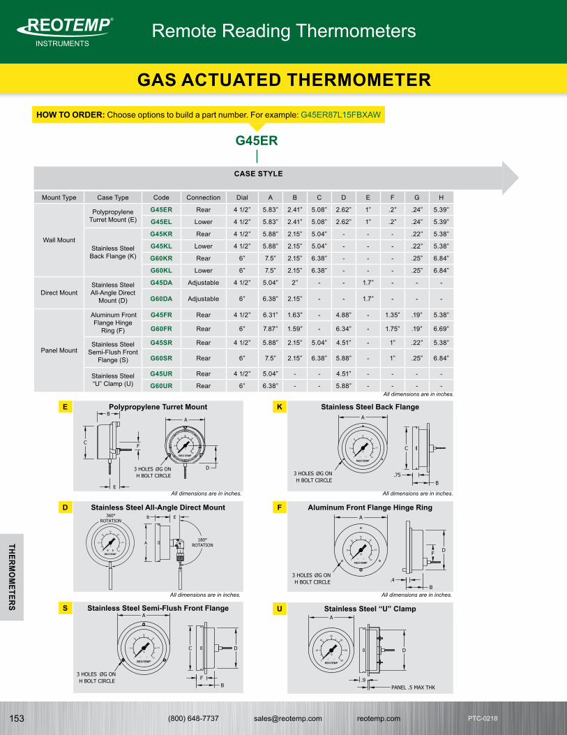
(800) 648-7737 [email protected] reotemp.com153
INSTRUMENTSMeasuring your world since 1965
®
THERMO
METERS
PTC-0218
Mount Type Case Type Code Connection Dial A B C D E F G H
Wall Mount
Polypropylene Turret Mount (E)
G45ER Rear 4 1/2” 5.83” 2.41” 5.08” 2.62” 1” .2” .24” 5.39”
G45EL Lower 4 1/2” 5.83” 2.41” 5.08” 2.62” 1” .2” .24” 5.39”
Stainless Steel Back Flange (K)
G45KR Rear 4 1/2” 5.88” 2.15” 5.04” - - - .22” 5.38”
G45KL Lower 4 1/2” 5.88” 2.15” 5.04” - - - .22” 5.38”
G60KR Rear 6” 7.5” 2.15” 6.38” - - - .25” 6.84”
G60KL Lower 6” 7.5” 2.15” 6.38” - - - .25” 6.84”
Direct MountStainless Steel All-Angle Direct
Mount (D)
G45DA Adjustable 4 1/2” 5.04” 2” - - 1.7” - - -
G60DA Adjustable 6” 6.38” 2.15” - - 1.7” - - -
Panel Mount
Aluminum Front Flange Hinge
Ring (F)
G45FR Rear 4 1/2” 6.31” 1.63” - 4.88” - 1.35” .19” 5.38”
G60FR Rear 6” 7.87” 1.59” - 6.34” - 1.75” .19” 6.69”
Stainless Steel Semi-Flush Front
Flange (S)
G45SR Rear 4 1/2” 5.88” 2.15” 5.04” 4.51” - 1” .22” 5.38”
G60SR Rear 6” 7.5” 2.15” 6.38” 5.88” - 1” .25” 6.84”
Stainless Steel “U” Clamp (U)
G45UR Rear 4 1/2” 5.04” - - 4.51” - - - -
G60UR Rear 6” 6.38” - - 5.88” - - - -
HOW TO ORDERHOW TO ORDER: Choose options to build a part number. For example: G45ER87L15FBXAW
G45ER
CASE STYLE
E Polypropylene Turret Mount
All dimensions are in inches.
All dimensions are in inches.
All dimensions are in inches.
All dimensions are in inches.
K Stainless Steel Back Flange
D Stainless Steel All-Angle Direct Mount F Aluminum Front Flange Hinge Ring
P37 - GAS ACTUATED FILLED SYSTEM THERMOMETER
°F
12000
800
200
400
600
1000
D
A
C
B
F
E
(E)
80
120
REOTEMP0
20
60
40
°F
100
A
C
B
3 HOLES �ØG ON H BOLT CIRCLE
.75
(K)
800
1200
REOTEMP0
200
600
400
°F
1000 A
B E
(D)
360°ROTATION
180°ROTATION
80
1200
20
60
40
°F
100
A
B.4
DF
(F)
80
120
REOTEMP0
20
60
40
°F
100
A
C
BF
D
(S)
80
1200
20
6040
°F100
A
PANEL .5 MAX THK.9
D
(U)
REOTEMP
REOTEMP
REOTEMP
3 HOLES �ØG ON H BOLT CIRCLE
3 HOLES �ØG ON H BOLT CIRCLE
3 HOLES �ØG ON H BOLT CIRCLE
S Stainless Steel Semi-Flush Front Flange U Stainless Steel “U” Clamp
P37 - GAS ACTUATED FILLED SYSTEM THERMOMETER
°F
12000
800
200
400
600
1000
D
A
C
B
F
E
(E)
80
120
REOTEMP0
20
60
40
°F
100
A
C
B
3 HOLES �ØG ON H BOLT CIRCLE
.75
(K)
800
1200
REOTEMP0
200
600
400
°F
1000 A
B E
(D)
360°ROTATION
180°ROTATION
80
1200
20
60
40
°F
100
A
B.4
DF
(F)
80
120
REOTEMP0
20
60
40
°F
100
A
C
BF
D
(S)
80
1200
20
6040
°F100
A
PANEL .5 MAX THK.9
D
(U)
REOTEMP
REOTEMP
REOTEMP
3 HOLES �ØG ON H BOLT CIRCLE
3 HOLES �ØG ON H BOLT CIRCLE
3 HOLES �ØG ON H BOLT CIRCLE
All dimensions are in inches. All dimensions are in inches.
All dimensions are in inches. All dimensions are in inches.
Remote Reading Thermometers
GAS ACTUATED THERMOMETER

(800) 648-7737 [email protected] reotemp.com 154
INSTRUMENTSMeasuring your world since 1965
®THERM
OM
ETERS
PTC-0218PTC-0218
87
THERMAL SYSTEM
All-Angle Direct Mount with 1/2” NPT (with “D” Case Only)04 = 4” Stem x 3/8” Diameter06 = 6” Stem x 3/8” Diameter09 = 9” Stem x 3/8” Diameter0? = 12” or Longer Stem x 3/8” Diameter (specify stem length)*
Sliding Union 1/2” NPT on Bendable Extension87 = 3/8” x 3” Active, 12” Bendable Extension88 = 3/8” x 3” Active, 18” Bendable Extension8X = 3/8” x 3” Active, Over 18” Bendable Extension (specify stem length)*
Plain Bulbs:11 = Plain Bulb, 3/8” x 3” Active, +12” Rigid Extension12 = Plain Bulb, 3/8’ x 3” Active
*Specify stem length. Example: G45DA - 0X - 12”- FBNote: All bulbs and capillaries are 316SS.
CAPILLARY LENGTH
L?? = Armored Capillary Length in ft. Lengths up to 99 ft. Omit for “D Case”. Example 5ft. = L05.
Note: Stainless steel spring armor is standard protection on all capillary. Capillary over 40 ft. require XSI Spiral Interlock Armor option.
L15
FB
TEMPERATURE RANGE
Ranges & Minor DivisionsFB = -320°F to 100°F, 5°FE = -120°F to 120°F, 2°FG = -40°F to 180°F, 2°FH = 0°F to 120°F, 1°FJ = 60°F to 120°F, 1°FL = 20°F to 240°F, 2°FN = 0°F to 300°F, 5°F0 = 150°F to 450°F, 5°FP = 50°F to 550°F, 5°FR = 50°F to 750°F, 5°FT = 400°F to 1200°F, 10°FX = 0°F to 1000°F, 10°CD = -200°C to 100°C, 5°CI = 0°C to 120°C, 1°CT = 200°C to 650°C, 5°
Dual Scale Ranges & DivisionsDB = -320°F to 100°F & -200°C to 40°C, 5° & 2°DE = -120°F to 120°F & -85°C to 50°C, 2° & 1°DG = -40°F to 180°F & -40°C to 80°C, 2° & 2°DH = 0°F to 120°F & -15°C to 50°C, 1° & 1°DJ = 60°F to 120°F & -15°C to 50°C, 1° & 1/2°DL = 20°F to 240°F & -5°C to 110°C, 2° & 1°DN = 0°F to 300°F & -10°C to 150°C, 5° & 1°D1 = 150°F to 450°F & 70°C to 230°C, 5° & 1°DP = 50°F to 550°F & 10°C to 290°C, 5° & 5°DR = 50°F to 750°F & 0°C to 400°C, 5° & 5°DT = 400°F to 1200°F & 200°C to 650°C, 10° & 5°
ACCESSORIES & OPTIONS
XAW = Acrylic Window*XSG = Safety Glass Window*XFR = Flush Mounting Ring for
“E” CaseXBF = 1/2” NPT Compression
Fitting for #11 Bulb (Attaches to 12” Extension, not Bulb)
XCF = 1/2” NPT Compression Fitting (Attaches to Spiral Interlock Armor. For #12 Bulb Only. Requires XSI Option.)
XSI = Spiral Interlock Armor (Required over 40 Feet)
XVD = Vibration Dampening Feature (Dampens Vibration - Available in all Rear Connected Models)
XTW = Thermowell (See Thermowell Table Below for Order Codes)
*Not Available for Aluminum Front Flange Hinge Ring (F) Case, F Case is Glass Only
XAWSTANDARD THERMOWELLS FOR 3/8” DIAMETER ELEMENTS
P A U 304SS 316SS
3/4” NPT
4” 2 1/2” ST4304-SB3 ST4316-SB3
6” 4 1/2” ST6304-SB3 ST6316-SB3
9” 7 1/2” ST9304-SB3 ST9316-SB3
12” 10 1/2” ST12304-SB3 ST12316-SB3
15” 13 1/2” ST15304-SB3 ST15316-SB3
18” 16 1/2” ST18304-SB3 ST18316-SB3
24” 22 1/2” ST24304-SB3 ST24316-SB3
1/2” NPT
4” 2 1/2” ST4304-HSB3 ST4316-HSB3
6” 4 1/2” ST6304-HSB3 ST6316-HSB3
9” 7 1/2” ST9304-HSB3 ST9316-HSB3
12” 10 1/2” ST12304-HSB3 ST12316-HSB3
15” 13 1/2” ST15304-HSB3 ST15316-HSB3
18” 16 1/2” ST18304-HSB3 ST18316-HSB3
24” 22 1/2” ST24304-HSB3 ST24316-HSB3
LAGGING THERMOWELLS FOR 3/8” DIAMETER ELEMENTS
P A U T 304SS 316SS
3/4” NPT
6” 2 1/2” 2” LG6304-SB3 LG6316-SB3
9” 4 1/2” 3” LG9304-SB3 LG9316-SB3
12” 7 1/2” 3” LG12304-SB3 LG12316-SB3
15” 10 1/2” 3” LG15304-SB3 LG15316-SB3
18” 13 1/2” 3” LG18304-SB3 LG18316-SB3
24” 19 1/2” 3” LG24304-SB3 LG24316-SB3
Standard Thermowells Lagging Thermowells
All dimensions are in inches.
All dimensions are in inches.
All dimensions are in inches.
P.38 - GAS ACTUATED FILLED SYSTEM THERMOMETER
1/2 NPT.75
1"U" INSERTION
∅.77
"A" STEM LENGTH
3/4 NPT ∅.385
.25
1/2 NPT.75
1"U" INSERTION
∅.68
"A" STEM LENGTH
1/2 NPT ∅.385
.25
1/2 NPT.75
"T" LAG"U" INSERTION
1
"A" STEM LENGTH
3/4 NPT ∅.385
.25
∅.77
P.38 - GAS ACTUATED FILLED SYSTEM THERMOMETER
1/2 NPT.75
1"U" INSERTION
∅.77
"A" STEM LENGTH
3/4 NPT ∅.385
.25
1/2 NPT.75
1"U" INSERTION
∅.68
"A" STEM LENGTH
1/2 NPT ∅.385
.25
1/2 NPT.75
"T" LAG"U" INSERTION
1
"A" STEM LENGTH
3/4 NPT ∅.385
.25
∅.77
P.38 - GAS ACTUATED FILLED SYSTEM THERMOMETER
1/2 NPT.75
1"U" INSERTION
∅.77
"A" STEM LENGTH
3/4 NPT ∅.385
.25
1/2 NPT.75
1"U" INSERTION
∅.68
"A" STEM LENGTH
1/2 NPT ∅.385
.25
1/2 NPT.75
"T" LAG"U" INSERTION
1
"A" STEM LENGTH
3/4 NPT ∅.385
.25
∅.77
All dimensions
are in inches.
GAS ACTUATED FILLED SYSTEM THERMOMETER
STEM LENGTH
Ø3/8”3”
ACTIVE LENGTH1/2” NPT
12 3”ACTIVE LENGTH
Ø3/8”
Ø3/8” EXT
BULB#11 BULB
ALL ANGLE BULB
ARMOR
ARMOR
REINFORCINGSPRING
3”ACTIVE LENGTH
Ø3/8”
#12 BULB
ARMOR
BENDABLE EXTENSION (87,88,8X)
EXTENSION LENGTH 3”ACTIVE LENGTH Ø3/8”
1/2” NPT
GAS ACTUATED FILLED SYSTEM THERMOMETER
STEM LENGTH
Ø3/8”3”
ACTIVE LENGTH1/2” NPT
12 3”ACTIVE LENGTH
Ø3/8”
Ø3/8” EXT
BULB#11 BULB
ALL ANGLE BULB
ARMOR
ARMOR
REINFORCINGSPRING
3”ACTIVE LENGTH
Ø3/8”
#12 BULB
ARMOR
BENDABLE EXTENSION (87,88,8X)
EXTENSION LENGTH 3”ACTIVE LENGTH Ø3/8”
1/2” NPT GAS ACTUATED FILLED SYSTEM THERMOMETER
STEM LENGTH
Ø3/8”3”
ACTIVE LENGTH1/2” NPT
12 3”ACTIVE LENGTH
Ø3/8”
Ø3/8” EXT
BULB#11 BULB
ALL ANGLE BULB
ARMOR
ARMOR
REINFORCINGSPRING
3”ACTIVE LENGTH
Ø3/8”
#12 BULB
ARMOR
BENDABLE EXTENSION (87,88,8X)
EXTENSION LENGTH 3”ACTIVE LENGTH Ø3/8”
1/2” NPT
GAS ACTUATED FILLED SYSTEM THERMOMETER
STEM LENGTH
Ø3/8”3”
ACTIVE LENGTH1/2” NPT
12 3”ACTIVE LENGTH
Ø3/8”
Ø3/8” EXT
BULB#11 BULB
ALL ANGLE BULB
ARMOR
ARMOR
REINFORCINGSPRING
3”ACTIVE LENGTH
Ø3/8”
#12 BULB
ARMOR
BENDABLE EXTENSION (87,88,8X)
EXTENSION LENGTH 3”ACTIVE LENGTH Ø3/8”
1/2” NPT
ALL ANGLE BULB
BENDABLE EXTENSION
11 12
GAS ACTUATED THERMOMETER
Remote Reading Thermometers

(800) 648-7737 [email protected] reotemp.com155
INSTRUMENTSMeasuring your world since 1965
®
THERMO
METERS
PTC-0218
• Accuracy ± 1% of Range Span• Can handle a wide temperature range up to 1200°F• Heavy-Duty Vibration and Shock Resistant• Stainless Steel Sealed Construction• Various mounting options available
REOTEMP’s Rugged Direct Drive System makes our series 45G the right choice for temperature indication in heavy-duty or high vibration applications. The all-stainless steel case and internals, along with the direct drive system, result in superior instrument life in severe environments.
Available in Four Styles
• WALL MOUNTED • FLUSH MOUNTED• FRONT FLANGE• ADJUSTABLE WALL
NITROGEN FILLEDDIRECT DRIVE SYSTEM
Accuracy
1%
FEATURES / BENEFITS
SPECIFICATIONS
Custom Logo Made in the USA
Accuracy ±1% of Range Span
Dial 4 1/2” Satin finish aluminum with black lines and numbers.
Case Material Stainless Steel
Bulb Stainless Steel Welded Construction
Actuation Nitrogen through Stainless Steel Direct Drive Bourdon Coil
Pointer Micrometer Adjustment Type
Lens Gasket Sealed Glass (Standard); Plexi Glass
Capillary Stainless steel protected by 1/4” diameter, Flexible Stainless Steel Armor or 3/16” diameter Plain Armor
DIRECT DRIVE REMOTE THERMOMETER
Remote Reading Thermometers

(800) 648-7737 [email protected] reotemp.com 156
INSTRUMENTSMeasuring your world since 1965
®THERM
OM
ETERS
PTC-0218PTC-0218
HOW TO ORDERHOW TO ORDER: Choose options to build a part number. For example: 45GW0500G112-EC
45GW 05 00 G112
ARMORED CAPILLARY LENGTH
05 = 5 Feet06 = 6 Feet10 = 10 Feet?? = Specify Length in Feet
Note: ?? = Length in feet (e.g. 05 = 5 feet)Note: Max length is?
TEMPERATURE RANGE BULB TYPE
G112 = 12” Bendable Extension with 1/2” NPT Compression Fitting (union)
G118 = 18” Bendable Extension with 1/2” NPT Compression Fitting (union)
G212 = 12” Plain Bulb with Rigid Extension
G224 = 24” Plain Bulb with Rigid Extension
MODEL
45GW = Wall Mount45GF = Flush Mount45GFF = Front Flange
with clamp45GAW = Adjustable
Wall Mount
Fahrenheit Ranges16 = -350°F to 150°F17 = -100°F to 100°F19 = -30°F to 120°F20 = -40°F to 200°F23 = 0°F to 150°F25 = 0°F to 200°F26 = 0°F to 240°F27 = 0°F to 300°F30 = 0°F to 400°F31 = 0°F to 500°F32 = 0°F to 600°F34 = 0°F to 800°F36 = 0°F to 1200°F
Celsius Ranges00 = -200°C to 100°C01 = -100°C to 100°C02 = -30°C to 60°C05 = -30°C to 120°C06 = -10°C to 150°C07 = 0°C to 100°C08 = 0°C to 200°C09 = 0°C to 240°C10 = 0°C to 300°C11 = 0°C to 400°C13 = 0°C to 500°C14 = 0°C to 600°C
ACCESSORIES
-EC = Electrical Contacts
-MP = Max. Hand Pointer
-SG = Tempered Glass-PY = Polycarbonate
Crystal
-EC
Note: Thermowells should be used whenever the stem or bulb would be exposed to pressure, corrosion, velocity, abrasion or shear forces. Thermowells also make it possible to remove the thermometer without losing pressure or the contents of the process.
All dimensions are in inches.
45GW Wall Mounted Complete with Bracket
P.40 - DIRECT DRIVE GAS ACTUATED THERMOMETER
�Ø518 �Ø6
2 34 3 Holes (�Ø9/32)
on �Ø5 12 Bolt Circle
1/8 to 1/4 Panel�Ø4 3
4 Cut Out7/16
�Ø41116
1 58
1/2
2 316
�Ø3
3 Holes (�Ø9/32)on �Ø2 5
16 Bolt Circle
12
3Sensitive Portion
�Ø3/8�Ø3/16
�Ø3/16
1 38
1/2 NPT
12
�Ø3/83Sensitive Portion
�Ø518
3 Holes (�Ø9/32)on �Ø51
2 Bolt Circle
1/2
45GF Flush Mounted Complete with U Bracket
P.40 - DIRECT DRIVE GAS ACTUATED THERMOMETER
�Ø518 �Ø6
2 34 3 Holes (�Ø9/32)
on �Ø5 12 Bolt Circle
1/8 to 1/4 Panel�Ø4 3
4 Cut Out7/16
�Ø41116
1 58
1/2
2 316
�Ø3
3 Holes (�Ø9/32)on �Ø2 5
16 Bolt Circle
12
3Sensitive Portion
�Ø3/8�Ø3/16
�Ø3/16
1 38
1/2 NPT
12
�Ø3/83Sensitive Portion
�Ø518
3 Holes (�Ø9/32)on �Ø51
2 Bolt Circle
1/2
45GFF Flush Mounted
P.40 - DIRECT DRIVE GAS ACTUATED THERMOMETER
�Ø518 �Ø6
2 34 3 Holes (�Ø9/32)
on �Ø5 12 Bolt Circle
1/8 to 1/4 Panel�Ø4 3
4 Cut Out7/16
�Ø41116
1 58
1/2
2 316
�Ø3
3 Holes (�Ø9/32)on �Ø2 5
16 Bolt Circle
12
3Sensitive Portion
�Ø3/8�Ø3/16
�Ø3/16
1 38
1/2 NPT
12
�Ø3/83Sensitive Portion
�Ø518
3 Holes (�Ø9/32)on �Ø51
2 Bolt Circle
1/2
45GAW Adjustable Wall MountedComplete with Flange
G1 Bulb
3/8" Diameter Bulb with 3/16" Bendable Complete with 1/2" NPT Compression Fitting All SS
P.40 - DIRECT DRIVE GAS ACTUATED THERMOMETER
�Ø518 �Ø6
2 34 3 Holes (�Ø9/32)
on �Ø5 12 Bolt Circle
1/8 to 1/4 Panel�Ø4 3
4 Cut Out7/16
�Ø41116
1 58
1/2
2 316
�Ø3
3 Holes (�Ø9/32)on �Ø2 5
16 Bolt Circle
12
3Sensitive Portion
�Ø3/8�Ø3/16
�Ø3/16
1 38
1/2 NPT
12
�Ø3/83Sensitive Portion
�Ø518
3 Holes (�Ø9/32)on �Ø51
2 Bolt Circle
1/2
G2 Bulb
3/8" Diameter Bulb with 3/8" Extension up to 48" with Optional 1/2"NPT Compression Fitting All SS
P.40 - DIRECT DRIVE GAS ACTUATED THERMOMETER
�Ø518 �Ø6
2 34 3 Holes (�Ø9/32)
on �Ø5 12 Bolt Circle
1/8 to 1/4 Panel�Ø4 3
4 Cut Out7/16
�Ø41116
1 58
1/2
2 316
�Ø3
3 Holes (�Ø9/32)on �Ø2 5
16 Bolt Circle
12
3Sensitive Portion
�Ø3/8�Ø3/16
�Ø3/16
1 38
1/2 NPT
12
�Ø3/83Sensitive Portion
�Ø518
3 Holes (�Ø9/32)on �Ø51
2 Bolt Circle
1/2All dimensions are in inches.
All dimensions are in inches. All dimensions are in inches.
All dimensions are in inches.All dimensions are in inches.
P.40 - DIRECT DRIVE GAS ACTUATED THERMOMETER
�Ø518 �Ø6
2 34 3 Holes (�Ø9/32)
on �Ø5 12 Bolt Circle
1/8 to 1/4 Panel�Ø4 3
4 Cut Out7/16
�Ø41116
1 58
1/2
2 316
�Ø3
3 Holes (�Ø9/32)on �Ø2 5
16 Bolt Circle
12
3Sensitive Portion
�Ø3/8�Ø3/16
�Ø3/16
1 38
1/2 NPT
12
�Ø3/83Sensitive Portion
�Ø518
3 Holes (�Ø9/32)on �Ø51
2 Bolt Circle
1/2
Remote Reading Thermometers
DIRECT DRIVE REMOTE THERMOMETER

(800) 648-7737 [email protected] reotemp.com157
INSTRUMENTSMeasuring your world since 1965
®
THERMO
METERS
PTC-0218
• Accuracy ± 1% of Range Span• Can handle a wide temperature range up to 1200°F.• Heavy-Duty Vibration and Shock Resistant• Stainless Steel Sealed Construction• Adjustable to any angle.
REOTEMP’s Rugged Direct Drive System makes our 45GR and 45LR the right choice for temperature indication in heavy- duty or high vibration applications. The all-stainless steel case and internals, along with the direct drive system, result in superior instrument life in severe environments.
EVERY ANGLE
Model 45GR Model 45LR
Accuracy
1%
FEATURES / BENEFITS
SPECIFICATIONS
Custom Logo Made in the USA
Accuracy ±1% of Range Span
Dial 4 1/2” Satin finish aluminum with black lines and numbers.
Case Material Stainless Steel
Bulb Stainless Steel Welded Construction
Actuation 45LR - Inert Liquid thru Stainless Steel Direct Drive Bourdon Coil. 45GR - Nitrogen thru Stainless Steel Direct Drive Bourdon Coil.
Pointer Micrometer Adjustment Type
Lens Gasket Sealed Glass (Standard); Polycarbonate
HOW TO ORDERHOW TO ORDER: Choose options to build a part number. For example: 45GR0400-ST6316
45GR 04 00
STEM LENGTH
04 = 4”06 = 6”09 = 9”12 = 12”15 = 15”18 = 18”24 = 24”
TEMPERATURE RANGEMODEL
45GR = Gas Actuated, 3/8” Stem
45LR = Inert Liquid Actuated, 1/4” Stem
Fahrenheit Ranges16 = -350°F to 150°F17 = -100°F to 100°F19 = -30°F to 120°F20 = -40°F to 200°F23 = 0°F to 150°F25 = 0°F to 200°F26 = 0°F to 240°F27 = 0°F to 300°F30 = 0°F to 400°F31 = 0°F to 500°F32 = 0°F to 600°F34 = 0°F to 800°F36 = 0°F to 1200°F
Celsius Ranges00 = -200°C to 100°C01 = -100°C to 100°C02 = -30°C to 60°C05 = -30°C to 120°C06 = -10°C to 150°C07 = 0°C to 100°C08 = 0°C to 200°C09 = 0°C to 240°C10 = 0°C to 300°C11 = 0°C to 400°C13 = 0°C to 500°C14 = 0°C to 600°C
ACCESSORIES
-EC = Electrical Contacts-MP = Max. Hand Pointer-SG = Tempered Glass-PY = Polycarbonate Crystal
For Additional Thermowell Types, See Pages 160-166
-ST6316
STANDARD THERMOWELLS WITH 3/4” NPT & 316SS
Stem Length
“U” Dim. 1/4” Element 3/8” Element
4” 2.5” ST4316 ST4316-B3
6” 4.5 ST6316 ST6316-B3
9” 7.5” ST9316 ST9316-B3
P.42 - DIRECT DRIVE GAS AND LIQUID FILLED THERMOMETER
StemLength
Ø1/4
3SensitivePortion
3/16
3/8
3SensitivePortion
180° Rotation5 1
8
2 18 11/16
Ø
Ø
Ø
All dimensions are in inches.
Remote Reading Thermometers
DIRECT DRIVE ALL ANGLE THERMOMETER

(800) 648-7737 [email protected] reotemp.com 158
INSTRUMENTSMeasuring your world since 1965
®THERM
OM
ETERS
PTC-0218PTC-0218
Accuracy: ± 1% Full Scale. (ASME B40.3)Case: Modern V-shape design with parts molded of polyester,
in black textured finish. Heavy glass protected front firmly secured by spring action.
Stem: Tapered bulb chambers are made of precision ground aluminum. The tapered chamber forms a metal contact with matching taper in the sockets assuring maximum speed of response to temperature changes. Graphite is used as a conducting media between bulb chamber and glass tube.
Locking Device: Adjustable case locknut and angle adjusting screw work independently to provide full 360º positioning of thermometer case and stem.
Tube & Capillary: Blue Spirit filled magnifying lens tube. Precision made to guarantee accuracy within 1% of scale range. Silicone shock mounting for lasting durability.
Scale: 9” scale with white coated aluminum and permanently baked bold black markings.
• Made to ASME B40.3 Specifications • Accuracy ± 1% Full Scale. (ASME B40.3) • One Year Warranty
REOTEMP’s Liqiud-In-Glass Industrial Thermometers are used in pipelines of all types, commercial building application (heating & cooling), process piping, tanks, boilers, etc.
Accuracy
1% FEATURES / BENEFITS
Made in the USA
HOW TO ORDERHOW TO ORDER: Choose options to build a part number. For example: 9VS35016SOC35B
9VS35 016
Fahrenheit Ranges411 = -40°F to 110°F; 2°118 = -10°F to 180°F; 2°212 = -20°F to 120°F; 2°012 = 0°F to 120°F; 1°016 = 0°F to 160°F; 2°318 = 30°F to 180°F; 2°324 = 30°F to 240°F; 2°330 = 30°F to 300°F; 2°
Celsius Ranges042 = -20°C to 45°C; 1°050 = 0°C to 50°C; 1°100 = 0°C to 100°C; 1°162 = 0°C to 160°C; 2°200 = 0°C to 200°C; 2°
STEM
9VS35 = 3 1/2” 9VS06 = 6” 9VS09 = 9”
THERMOWELL
SOC35B
STANDARD THERMOWELLS (SEPERABLE SOCKETS) WITH 3/4” NPT
MaterialSocket Style
“A” Stem Length
“U” Insertion Length
“T” Extension Length Code
Brass
Standard
3 1/2” 2 1/2” N/A SOC35B
6” 5” N/A SOC06B
9” 8” N/A SOC09B
Extension Neck
6” 2 1/2” 2 1/2” SEN06B
9” 5 1/2” 2 1/2” SEN09B
304SS
Standard
3 1/2” 2 1/2” N/A SOC35S
6” 5” N/A SOC06S
9” 8” N/A SOC09S
Extension Neck
6” 2 1/2” 2 1/2” SEN06S
9” 5 1/2” 2 1/2” SEN09SStandard Thermowell w/ Extension Neck (Lag)
Note: Thermowells should be used whenever the stem or bulb would be exposed to pressure, corrosion, velocity, abrasion or shear forces. Thermowells also make it possible to remove the thermometer without losing pressure or the contents of the process.
SPECIFICATIONS
TEMPERATURE RANGE
P43 - LIQUID-IN-GLASS INDUSTRIAL THERMOMETER
U
A
U
A
T
1
w/ EXTENSION NECK (LAG)
STANDARD
P43 - LIQUID-IN-GLASS INDUSTRIAL THERMOMETER
U
A
U
A
T
1
w/ EXTENSION NECK (LAG)
STANDARD
All dimensions are in inches.
LIQUID-IN-GLASS THERMOMETER
Liquid-In-Glass

(800) 648-7737 [email protected] reotemp.com 159
INSTRUMENTSMeasuring your world since 1965
®THERM
OW
ELLS
PTC-0218PTC-0218
THERMOWELLS
REOTEMP Thermowells are manufactured to the highest quality and precision, ensuring a durable product for even the most severe applications. Whether it is a custom design or a common configuration, REOTEMP responds quickly to exceed customer requirements.
INSTRUMENTSMeasuring your world since 1965
®

(800) 648-7737 [email protected] reotemp.com160
INSTRUMENTSMeasuring your world since 1965
®
THERMO
WELLS
PTC-0218
• Wake Frequency Calculation• Hydrostatic Test• NACE Certified• Material Certificate• Special Marking (Stamping)• Plug & Chain• PMI
• Machined from Solid Material• Protects Your Instrument from the Process• Easy Removal of Instrument for Calibration or
Replacement
Threaded
FEATURES / BENEFITS
OPTIONS
REOTEMP Threaded Thermowells make it possible to remove an instrument without dropping pressure or losing contents of the process. Thermowells also protect the instrument from getting bent by the process media. Threaded thermowells are perfect for applications that require infrequent replacement and are commonly installed on smaller pipes or vessels. They are best suited for non-corrosive media. REOTEMP threaded thermowells are machined from solid bar stock.
STANDARD DIMENSIONS
Stem “A” Standard “U”
Lagging “U”
Overall Length
2.5" 1.625" N/A 2.875"
4" 2.5" N/A 4.25"
6" 4.5" 2.5" 6.25"
9" 7.5" 4.5" 9.25"
12" 10.5" 7.5" 12.25"
All dimensions are in inches.
P.45 - THREADED THERMOWELLS
1 3 4"U" DIM
INSERTION LENGTH
3/4
.26 BORE2 1
21/4
1/2
1/2 NPT
3/4 NPT
1/2 NPT
3/4 NPT3/4
"T" LAGEXTENSION 1 "U" DIM
INSERTION LENGTH
3/4
1/2
.26 BORE
2 12
1/4
Ø
Ø
Ø
Ø
Ø
Ø
A
A
P.45 - THREADED THERMOWELLS
1 3 4"U" DIM
INSERTION LENGTH
3/4
.26 BORE2 1
21/4
1/2
1/2 NPT
3/4 NPT
1/2 NPT
3/4 NPT3/4
"T" LAGEXTENSION 1 "U" DIM
INSERTION LENGTH
3/4
1/2
.26 BORE
2 12
1/4
Ø
Ø
Ø
Ø
Ø
Ø
A
AAll dimensions are in inches.
Standard
Lagging
INSTRUMENTSMeasuring your world since 1965
®
THREADED THERMOWELLS
Thermowells

(800) 648-7737 [email protected] reotemp.com 161
INSTRUMENTSMeasuring your world since 1965
®THERM
OW
ELLS
PTC-0218PTC-0218
ü Check Stockü Configure Part #
ü Get Priceü Generate a Custom Engineering DrawingVisit reotemp.com
TYPE
ST = ThreadedLG = Threaded
Lagging
“A” STEM LENGTH
2.5 = 2.5”4 = 4”6 = 6”9 = 9”12 = 12”
MATERIAL
304 = 304SS316 = 316SS316L = 316L SSB = BrassC = Carbon Steel (1018)G = Hastelloy BH = Hastelloy CM = Monel/A400T = TitaniumY = Inconel 600A = Alloy 105 Carbon
Stainless SteelD = Alloy 205 = F5 AlloyP = PTFE Coated
316SSN = F22 Alloy
Other materialsavailable. Contact REOTEMP customer service for more information.
PROCESS CONNECTION
“ ” = 3/4” NPT (std.)1 = 1” NPTH = 1/2” NPT2 = 1.5” NPT
SHANK
“ ” = Stepped (std.)*
T = TaperedS = Straight
*Not available with .385 bore.
BORE DIAMETER
“ ” = .260 (std.)B3 = .385B5 = .515I3 = 3/4” NPT
Internal Thread
Other bore and internal thread sizes available.
OPTIONS
EP = External Pressure TestIT = Internal Pressure Testing (5 min.
test)MT = Material CertificateML = Mill CertificateMR = NACE MR-01-75 ApprovalM3 = NACE MR-01-03 ApprovalPM = Positive Material Identification
(PMI)P4 = SS 304 Plug & ChainP6 = SS 316 Plug & ChainPB = Brass Plug & Chain R2 = Special Surface Finish (Ra 20
max)T1 = Tantalum Coating/ Halar CoatingT2 = Teflon Coating (Specify PFA or
PTFE)T3 = Tungsten Carbide Coating TM = Special Marking (Stamping)TS = SS Tag (attached)WK = Wake Frequency Calculation
HOW TO ORDERHOW TO ORDER: Choose options to build a part number. For example: ST6316-ML
ST 6 316 - -ML
STEPPED SHANK
Bore Dia.
Ext. Thread
Size
Shank Dia. “Q1” (U>2.5)
Shank Dia. “Q2”
.260" 1/2" NPT .625" .500"
.260" 3/4" NPT .750" .500"
.260" 1" NPT .875" .500"
STRAIGHT SHANK
Bore Dia.
Ext. Thread
Size
Shank Dia. “Q” (U≤2.5)
Shank Dia. “Q” (U>2.5)
.260" 1/2" NPT .500" .625"
.260" 3/4" NPT .500" .625"
.260" 1" NPT .750" .875"
.385" 1/2" NPT .680" .680"
.385" 3/4" NPT .766" .766"
.385" 1" NPT .875" .875"
TAPERED SHANK
Bore Dia.
Ext. Thread
Size
Shank Dia. “Q1”
Shank Dia. “Q2”
.260" 1/2" NPT .680" .625"
.260" 3/4" NPT .875" .625"
.260" 1" NPT 1.062" .625"
.385" 1/2" NPT .680" .625"
.385" 3/4" NPT .875" .766"
.385" 1" NPT 1.062" .766"
P.46 - THREADED THERMOWELLS
Standard Stepped Shank Straight Shank Tapered Shank
Q2Q1
Q
Q1
Q2
P.46 - THREADED THERMOWELLS
Standard Stepped Shank Straight Shank Tapered Shank
Q2Q1
Q
Q1
Q2
P.46 - THREADED THERMOWELLS
Standard Stepped Shank Straight Shank Tapered Shank
Q2Q1
Q
Q1
Q2
All dimensions are in inches.All dimensions are in inches.All dimensions are in inches.
THREADED THERMOWELLS
Thermowells

(800) 648-7737 [email protected] reotemp.com162
INSTRUMENTSMeasuring your world since 1965
®
THERMO
WELLS
PTC-0218
Socket Weld
• Wake Frequency Calculation• Hydrostatic Test• NACE Certified• Material Certificate• Special Marking (Stamping)• Plug & Chain• PMI
• High Quality Connection• Ideal for High Temperature and High Pressure Applications
with Non-corrosive Media• Socket Weld or Standard Weld-in• Easy Removal of Instrument for Calibration or
Replacement
FEATURES / BENEFITS
OPTIONS
REOTEMP Welded Thermowells make it possible to remove an instrument without dropping pressure or losing the contents of the process. Thermowells also protect the instrument from getting bent by the process media. Weld-in thermowells are welded directly to a pipe or tank, providing a very high quality connection. Because they are welded, they should only be used when access is not required and corrosion is not an issue. Common installations include high temperature and high pressure applications with non-corrosive media. REOTEMP weld-in thermowells are machined from bar stock.
SOCKET WELD STEPPED SHANK
Bore Dia. “B”
Nominal Pipe
Size “P”
O.D.“D”
Shank Dia. “Q1”(U≤2.5)
Shank Dia. “Q1” (U>2.5)
Shank Dia. “Q2”
.260" 3/4" 1.050" .500" .750" .500"
.260" 1" 1.315" .750" .875" .500"
.260" 1.5" 1.900" 1.000" 1.120" .500"
SOCKET WELD STRAIGHT SHANK
Bore Dia. “B”
NominalPipe
Size “P”
O.D.“D”
Shank Dia. “Q2”
(U≤2.5)
Shank Dia. “Q2”
(U>2.5)
.260" 3/4" 1.050" .500" .750"
.260" 1" 1.315" .750" .875"
.260" 1.5" 1.900" 1.00" 1.12"
.385" 3/4" 1.050" .766" .766"
.385" 1" 1.315" .766" .875"
.385" 1.5" 1.900" 1.00" 1.12"
SOCKET WELD TAPERED SHANK
Bore Dia. “B”
Nominal Pipe
Size “P”
O.D.“D”
Shank Dia. “Q1”
Shank Dia. “Q2”
.260" 3/4" 1.050" .750" .625"
.260" 1" 1.315" 1.000" .625"
.260" 1.5" 1.900" 1.370" .625"
All dimensions are in inches.
P.47 - WELD-IN THERMOMETERS
D
1 34
U
Q1
B
1/4
Q2
A
1/2 NPT
WELDED THERMOWELLS
Thermowells

(800) 648-7737 [email protected] reotemp.com 163
INSTRUMENTSMeasuring your world since 1965
®THERM
OW
ELLS
PTC-0218PTC-0218
TYPE
SW = Socket WeldSWL = Socket Weld
w/ LaggingWI = Weld-InWIL = Weld-In w/
Lagging
“A” STEM LENGTH
2.5 = 2.5”4 = 4”6 = 6”9 = 9”12 = 12”
MATERIAL
304 = 304SS316 = 316SS316L = 316L SSB = BrassC = Carbon Steel
(1018)G = Hastelloy BH = Hastelloy CM = Monel/A400T = TitaniumY = Inconel 600A = Alloy 105 Carbon
Stainless SteelD = Alloy 205 = F5 AlloyP = PTFE Coated
316SSN = F22 Alloy
Other materialsavailable. Contact REOTEMP customer service for more information.
PROCESS CONNECTION
“ ” = 3/4” Pipe Nominal (1.050” OD) (std.)
P1 = 1” Pipe Nominal (1.315” OD)
P2 = 1.5” Pipe NominalP3 = 2” Pipe Nominal
SHANK
“ ” = Stepped (std.)*
T = TaperedS = Straight
*Not available with .385 bore.
BORE DIAMETER
“ ” = .260 (std.)B3 = .385B5 = .515I3 = 3/4” NPT
Internal Thread
Other bore and internal thread sizes available.
OPTIONS
EP = External Pressure TestIT = Internal Pressure Testing (5 min.
test)MT = Material CertificateML = Mill CertificateMR = NACE MR-01-75 ApprovalM3 = NACE MR-01-03 ApprovalPM = Positive Material Identification
(PMI)P4 = SS 304 Plug & ChainP6 = SS 316 Plug & ChainPB = Brass Plug & Chain R2 = Special Surface Finish (Ra 20
max)T1 = Tantalum Coating/ Halar CoatingT2 = Teflon Coating (Specify PFA or
PTFE)T3 = Tungsten Carbide Coating TM = Special Marking (Stamping)TS = SS Tag (attached)WK = Wake Frequency Calculation
HOW TO ORDERHOW TO ORDER: Choose options to build a part number. For example: SW6316-P1T-ML
SW 6 316 P1 T- -ML
ü Check Stockü Configure Part #
ü Get Priceü Generate a Custom Engineering DrawingVisit reotemp.com
WELD-IN TAPERED SHANK
Bore Dia. “B”
Nominal Pipe
Size “P”
O.D.“D”
Tip Dia “Q”
.260 in3/4" 1.050" .625"
1" 1.315" .766"
.385 in3/4" 1.050" .625"
1" 1.315" .766"All dimensions are in inches.
P.48 - WELD-IN TAPERED THERMOWELL
D
1 34 U
Q
1/4AB
1/2 NPT
+ T (Lag if Any)
Weld-In
WELDED THERMOWELLS
Thermowells

(800) 648-7737 [email protected] reotemp.com164
INSTRUMENTSMeasuring your world since 1965
®
THERMO
WELLS
PTC-0218
• Wake Frequency Calculation• Hydrostatic Test• Full Penetration Welds• NACE Certified• Material Certificates• PMI
• Die Stamped with Material• Ideal for High Pressure and High Corrosion Applications
Requiring Frequent Replacement• Easy Removal of Instrument for Calibration or
Replacement
FEATURES / BENEFITS
OPTIONS
REOTEMP’s Flanged Thermowells make it possible to remove an instrument without dropping pressure or losing contents of the process. Thermowells also protect the instrument from getting bent by the process media. Flanged thermowells are the preferred well for applications that require frequent removal or replacement due to corrosion or other hazards. Flanged wells bolt to a mating flange that is installed on the process piping. Common installations include large pipes with high pressure and high corrosion.
TAPERED SHANK
Bore Dia. “B”
Flange Size
Shank Dia. “Q1”
Shank Dia. “Q2”
.260" 3/4" .750" .625"
.260" 1" .875" .625"
.260" 1-1/2" & up 1.062" .625"
.385" 3/4" .750" .625"
.385" 1" .875" .766"
.385" 1-1/2" & up 1.062" .766"
STEPPED SHANK
Bore Dia. “B”
Shank Dia. “Q1”
Shank Dia. “Q2”
.260" .750" .500"
STRAIGHT SHANK
Bore Dia.“B”
Shank Dia. “Q2”
.260" .750"
.385" .875"
VAN STONE SIZE
Nominal Pipe
Size “P”
O.D.“D”
Raised Face
Dia. “R”
1" 1.315" 2.000"
1.5" 1.900" 2.875"
VAN STONE
Bore Dia. “B”
Shank Dia. “Q”
.260" .750"
.385" .875"
Flanged Van Stone
P.49 - FLANGED THERMOWELLS
1.25
2.25 + T U
Q1B
AL
.25
D
2.25 + T U
LA
.25
Q2Q1R
B
"P" FLANGE1/2-14 NPT
LAP JOINT COVER FLANGESUPPLIED SEPARATELY
"P" PIPE
Q2
1/2-14 NPT
P.49 - FLANGED THERMOWELLS
1.25
2.25 + T U
Q1B
AL
.25
D
2.25 + T U
LA
.25
Q2Q1R
B
"P" FLANGE1/2-14 NPT
LAP JOINT COVER FLANGESUPPLIED SEPARATELY
"P" PIPE
Q2
1/2-14 NPT
All dimensions are in inches.
All dimensions are in inches.
FLANGED THERMOWELLS
Thermowells

(800) 648-7737 [email protected] reotemp.com 165
INSTRUMENTSMeasuring your world since 1965
®THERM
OW
ELLS
PTC-0218PTC-0218
HOW TO ORDERHOW TO ORDER: Choose options to build a part number. For example: 151R2STU040L062-ML
15 1 R
FLANGE SIZE
05 = 1/2” 07 = 3/4”10 = 1”15 = 1.5”20 = 2”25 = 2.5”30 = 3”
FLANGE RATING
1 = 150# 3 = 300#6 = 600#9 = 900 - 1500#5 = 2500#V = VanStone
SEALINGFACE
R = Raised Face F = Flat FaceJ = RTJ (Ring
Type Joint)Q = Other (Spec-
ify)
BORE DIAMETER
2 = .260” (For 1/4” Stem)
3 = .385” (For 3/8” Stem)
Q = Other (Specify)
*Not available with .385 bore.
MATERIAL
S = 316SSF = 304SSC = Carbon SteelD = Carp. 20/Alloy 20G = Hastelloy BH = Hastelloy CL = F11 AlloyM = MonelY = Inconel (600)U = Tantalum LinedZ = Zirconium (316 flg)V = 317SST = TitaniumK = 316/Stellite
Coating2 = Alloy 205 = F5 AlloyN = F22 AlloyP = PTFE Coated
316SS
SHANK STYLE
T = TaperedS = StraightP = Stepped*R = Tapered w/
Support RingQ = Other
*Not available with .385 bore.
2 S T U040L062
“U” Dimensions Overall Length
U020 = 2" L042 = 4.25"
U040 = 4" L062 = 6.255"
U070 = 7" L092 = 9.25"
U100 = 10" L122 = 12.25"
U130 = 13" L152 = 15.25"
U160 = 16" L182 = 18.25"
U220 = 22" L242 = 24.25"
U225 = 22.5" L247 = 24.75"
M250 = 250mm M307 = 307mm
Note: Rows above indicate standard pairings, for example: a 2” U dimension comes standard with a 4.25” overall length.
“U” DIMENSIONS & OVERALL LENGTH
ü Check Stockü Configure Part #
ü Get Priceü Generate a Custom Engineering DrawingVisit reotemp.com
OPTIONS
EP = External Pressure TestIT = Internal Pressure Testing (5 min.
test)MT = Material CertificateML = Mill CertificateMR = NACE MR-01-75 ApprovalM3 = NACE MR-01-03 ApprovalPM = Positive Material Identification
(PMI)P4 = SS 304 Plug & ChainP6 = SS 316 Plug & ChainPB = Brass Plug & Chain R2 = Special Surface Finish (Ra 20
max)T1 = Tantalum Coating/ Halar CoatingT2 = Teflon Coating (Specify PFA or
PTFE)T3 = Tungsten Carbide Coating TM = Special Marking (Stamping)TS = SS Tag (attached)WK = Wake Frequency Calculation
-ML
FLANGED THERMOWELLS
Thermowells

(800) 648-7737 [email protected] reotemp.com166
INSTRUMENTSMeasuring your world since 1965
®
THERMO
WELLS
PTC-0218
• Smooth Surface for Easy Cleaning (RA32 or Better)• Provides Sanitary Protection for Temperature Probes• All 316L Stainless Steel Construction• Fast Installation and Removal• Ideal for Food, Beverage, Biotech, and Pharmaceutical
Applications• Exceeds 3A #4 Finish• Easy Removal of Instrument for Calibration or
Replacement
REOTEMP’s Sanitary Thermowells make it possible to remove an instrument without dropping pressure or losing contents. Each stainless steel Thermowell is die stamped with type of material from which it is made. Sanitary wells have a smooth surface (RA32 or Better) and a Tri-Clamp® connection which allows for easy cleaning to prevent contamination of the process. They are used in the Dairy, Food Processing and Pharmaceutical industries.
FEATURES / BENEFITS
Certified
Tri-Clamp® Size
“A” Stem Length
“U” Dimension “C” Dimension Code
1-1/2"
2-1/2" 1-5/8"
2"
STF1.5-2.5
4" 2-1/2" STF1.5-4
6" 4-1/2" STF1.5-6
9" 7-1/2" STF1.5-9
2"
2-1/2" 1-5/8"
2.5"
STF2-2.5
4" 2-1/2" STF2-4
6" 4-1/2" STF2-6
9" 7-1/2" STF2-9
2-1/2"
2-1/2" 1-5/8"
3"
STF2.5-2.5
4" 2-1/2" STF2.5-4
6" 4-1/2" STF2.5-6
9" 7-1/2" STF2.5-9
3"
2-1/2" 1-5/8"
3.6"
STF3-2.5
4" 2-1/2" STF3-4
6" 4-1/2" STF3-6
9" 7-1/2" STF3-9
HOW TO ORDER: Choose a code to make your selection. For example: STF1.5-2.5
STF1.5-2.5
Tri-Clamp®® is a registered trademark of Alpha Laval Inc.
All dimensions are in inches.
P.51 SANITARY THERMOWELLS
C
1/8
A
�Ø3/8
�Ø.26 1/4
U
1/2 NPT
SANITARY THERMOWELLS
Thermowells

(800) 648-7737 [email protected] reotemp.com 167
INSTRUMENTSMeasuring your world since 1965
®THERM
OW
ELLS
PTC-0218PTC-0218
NOTES

(800) 648-7737 [email protected] reotemp.com168
INSTRUMENTSMeasuring your world since 1965
®
THERMO
WELLS
PTC-0218
VISIT OUR WEBSITE
.COMINSTRUMENTS
WARRANTY & EVALUATION POLICY
ü Check Stockü Configure Part #
ü Get Priceü Download PDF Data SheetsVisit reotemp.com
> Provide industry leading customer satisfaction with a focus on fast turnaround, friendly service and keeping it easy to do business with REOTEMP. Make it Quick and Easy!
> Focus on manufacturing quality instruments, continuous improvement and adding value to our product and services.
> Build long-lasting and rewarding relationships with the people we do business with.
> Maintain an enjoyable, fulfilling work environment for our employees.
> Build a strong REOTEMP brand and reputation in the industrial markets where we compete.
> Achieve planned, sustained growth in our target markets both in the US and internationally.
REOTEMP'S GUIDING PRINCIPLES
REOTEMP warrants all pressure and temperature measurement products against defective workmanship or materials under normal use and service for the following periods after the date of shipment.
FIVE YEAR WARRANTY• Process Grade Bimetal Thermometers (3", 4", and 5" dial
sizes)
THREE YEAR WARRANTY• Industrial Pressure and Differential Pressure Gauges• Valves and Manifolds
ONE YEAR WARRANTY• Diaphragm Seals• Pressure Transmitters and Switches• OEM Bimetal Thermometers• Digital Thermometers• Remote Reading Thermometers• Thermowells• Accessories and Other Items
REOTEMP’s liability is limited to repair or replacement at the factory, shipping charges prepaid. This warranty does not cover deterioration from normal wear and tear, exposure to corrosive materials, exposure to temperatures or pressures in excess of those recommended, excessive vibration, forces, or abrasion which cause deformation of component parts. This warranty is expressly in lieu of any other warranty, expressed or implied. REOTEMP shall not be liable for any defect or consequential damages arising out of any defects or from any cause whatsoever. Suitability of product for the customer’s application rests with the customer; REOTEMP does not warrant suitability of its products for the application chosen by the customer.
REOTEMP will only accept shipments with returned product that are accompanied with a return authorization issued by REOTEMP. Please respect the health and safety of our employees by cleaning goods before return, disclosing any chemicals or foreign substance that may be on returned product and enclosing MSDS information. Handling and cleaning fees may apply.
REOTEMP reserves the right to make product improvements and change its specifications stated throughout the catalog at any time without notification. Please contact the factory on all critical dimensions and specifications for verification.
PTC-0218

(800) 648-7737 [email protected] reotemp.com 169
INSTRUMENTSMeasuring your world since 1965
®THERM
OW
ELLS
PTC-0218PTC-0218
PTC-0218© 2018 REOTEMP Instrument Corp.
Measuring your world since 1965 TM
U.S. (800) 648-7737Int’l (00) 1-858-784-0710
Fax (858) 784-0720
10656 Roselle St.San Diego, CA 92121
United States
OTHER REOTEMP CATALOGS
Thermocouples & RTDsHead and Stem AssembliesTemperature TransmittersSanitary 3-A RTDsThermowells & AccessoriesMultipoint SensorsHandheld ProbesWeld Pad TCs