investigation of the performance of pulsating heat pipe subject
TRANSCRIPT

Experimental Thermal and Fluid Science 54 (2014) 85–92
Contents lists available at ScienceDirect
Experimental Thermal and Fluid Science
journal homepage: www.elsevier .com/locate /et fs
Investigation of the performance of pulsating heat pipe subjectto uniform/alternating tube diameters
http://dx.doi.org/10.1016/j.expthermflusci.2014.01.0190894-1777/� 2014 Elsevier Inc. All rights reserved.
⇑ Corresponding author. Tel.: +886 3 5712121x55105.E-mail address: [email protected] (C.-C. Wang).
Chih-Yung Tseng a, Kai-Shing Yang a, Kuo-Hsiang Chien a, Ming-Shan Jeng a, Chi-Chuan Wang b,⇑a Green Energy & Environment Research Laboratories, Industrial Technology Research Institute, Hsinchu 310, Taiwanb Department of Mechanical Engineering, National Chiao Tung University, Hsinchu 300, Taiwan
a r t i c l e i n f o a b s t r a c t
Article history:Received 31 October 2013Received in revised form 28 January 2014Accepted 28 January 2014Available online 5 February 2014
Keywords:Pulsating heat pipeHorizontal arrangementAlternating diameter
The present study examines the performance of closed-loop pulsating heat pipes (CLPHPs) with an ID of2.4 mm. The effect of uniform and alternating tube diameter on the performance is investigated. Theworking fluids include distilled water, methanol and HFE-7100. Tests are performed with both horizontaland vertical arrangement. For the horizontal arrangement, when compared to uniform design, thealternating channel design can be started at a rather low heat input with a much smaller thermal resis-tance. Normally the thermal resistance is decreased with the rise of heat input, and reveals a minimumvalue at a certain heat input followed by shows a marginal rise when the heat input is increased further.Both uniform and alternating design reveals the similar trend. For the vertical arrangement, the thermalresistance is much lower than that in horizontal arrangement. Different from that in horizontal arrange-ment, the thermal resistance shows a continuous decline against heat input for all the working fluids. Fora low input power, CLPHP with HFE-7100 shows the least thermal resistance. By contrast, CLPHP withdistilled water shows the smallest thermal resistance when the input power is increased over 60 W.
� 2014 Elsevier Inc. All rights reserved.
1. Introduction
The number of transistors on integrated circuits followed the socalled Moore’s law in which the integrated circuits double approx-imately every two years in a specific area. This eventually leads toan enormous rise of heat density, placing a major roadblock forfurther miniature. As a consequence, improving the performanceof the thermal module is imperative to maintain the junction tem-perature of the electronic devices below certain threshold. One ofthe most successful heat removal designs is heat pipe which isnow used in every aspect of electronic cooling applications. How-ever, convectional heat pipes normally suffers from comparativelylower maximum heat dissipation and shorter operational distanceas used in electronic cooling. In this regard, multiple heat pipes arecommonly employed to tackle high flux demand. However, thewick structure in the conventional heat pipe limits the transportdistance. In this regard, the concept of pulsating heat pipe (PHP)is proposed to tackle the foregoing problems (Akachi [1,2]). Unliketraditional coaxial heat pipes, the pulsating heat pipes are madefrom a long continuous capillary tube bent into many turns andthey are free from wick. The PHPs is also easier to manufacture
with fewer operating limitations [3]. Yet they required more work-ing fluid than conventional heat pipes [4]. The heat transfer of PHPoccurs due to self-exciting oscillation which may be driven by fastfluctuating pressure wave engendered from nucleate boiling andsubsequent condensation of the working fluid [5]. In fact, as ex-plained by Shafii et al. [5], due to the pulsation of the working fluidin the axial direction of the tube, heat is transported from theevaporator section to the condenser section. The heat input, whichis the driving force, increases the pressure of the vapor plug in theevaporator section. In turn, this pressure increase will push theneighboring vapor plugs and liquid slugs toward the condenserwhere a lower pressure prevails.
There had been quite a few studies in association with the per-formance of PHPs. Khandekar et al. [6,7] conducted experiments ona PHP made of 2 mm copper capillary tube with three differentworking fluids – water, ethanol and R-123. The PHP was testedin vertical (bottom heat mode) and horizontal orientation. Theirresults demonstrated that the effect of input power and volumetricfilling ratio of the working fluid on the thermal performance isquite essential. Qu et al. [4] performed tests of a 2 mm copper cap-illary PHP having 5 turns, and ethanol was selected as the workingfluid with filling ratios (FR) of 30%, 50% and 70%. Three types ofattractors were identified under different power inputs. Based ontheir nonlinear analysis and tests, the best fill ratio is found to beat 50%. There were some studies associated the working fluids

Nomenclature
cp specific heat of water (J kg�1 K�1)D diameter (m)_m mass flow rate of coolant water (kg s�1)
Q heat transfer rate (W)R thermal resistance (K W�1)T temperature (K)
Tc,avg average surface temperature at the condenser (K)Te,acg average surface temperature at the evaporator (K)Tw,in temperature at the chilled water inlet (K)Tw,out temperature at the chilled water outlet (K)
86 C.-Y. Tseng et al. / Experimental Thermal and Fluid Science 54 (2014) 85–92
applicable PHP. For instance, Fumoto et al. [8] conducted PHP madeof flat aluminum plate. The working fluid is n-butane/water mix-ture and the supplied power is 10–70 W. It shows that the 30%higher power input can be achieved for 1% n-butane watersolution. Similar results for water, ethanol, and methanol werereported by Vassilev et al. [9], and the best filling ratios for water,ethanol, methanol are 30%, 30%, and 20%, respectively. Kammuang-lue et al. [10] performed experiments for ethanol, water and R-123.They found that the thermal resistance is related to viscosity dur-ing horizontal operation. Groll and Khandekar [11] found the bestfilling ratio is around 30–50% for ethanol under vertical operation.Qu and Wang [12] reported a best filling ratio of 40% for ethanol,water, and the results are insensitive to change of tube diameterand evaporator size.
Though PHP has been experimentally tested in some highpower electronic cooling applications, large-scale commercializa-tion of the PHP is still not available due to some practical concerns.For instance, PHP with fewer turn is unable to function properlysubject to horizontal arrangement [13]. The problem can be reme-died by adding a check valve or more turns. However, introducing acheck valve inevitably complicates the system operation and add-ing more turns will increase the size of PHPs. Hence Chien et al.[14] introduce a novel concept by having different sizes of capillarytubes rather than conventional uniform tube diameters in a PHP.Their design made use the uneven capillary force and was provento operate successfully under horizontal arrangement. The originaldesign of [14] was applicable in a flat panel which shows less flex-ibility when the space constraint is conspicuous. Also, it may notdirectly apply to the conventional corrugated PHP configuration.Hence, the present study aims to extend the applicability of theprevious concept to the commonly corrugated PHPs. Moreover,the effect of working fluids on the performance of the PHP is alsoinvestigated. It will be found in subsequent discussion that theselection of working fluid casts a significant impact on the perfor-mance of PHPs. The proposed design can be used in a larger PHPssubject to long distance transportation and also overcome theinfluence of gravity.
2. Experimental apparatus
The schematic of the present apparatus for the closed loop PHP(CLPHP) experiment is shown in Fig. 1. Besides the tested CLPHPsamples, the experimental setup comprises an evaporator section,a water loop served as a condenser, and the measurement devicesas well as a data acquisition system. The evaporator section ismade of a copper block (70 mm � 230 mm � 20 mm) for heatingthe CLPHP by providing electric power from a power supply tothe heater which is embedded in the copper block. In order to min-imize the heat loss from the heater to the environment, a bakeliteboard having a rather low thermal conductivity is installedbeneath the copper block. As for the water loop, the inlet watertemperature for cooling the CLPHP is controlled by a precisionwater thermostat and the water flow rate is measured by a mag-netic flow meter.
In this study, two CLPHPs having either uniform or alternatingtube diameter were tested. Detailed geometries and dimensionsof the tested CLPHPs are shown in Fig. 2(a). The CLPHPs were madeof copper tube with an overall size of 200 mm � 210 mm � 3 mmhaving 8 parallel channels. The outer diameter of the uniformCLPHP is 3 mm having a wall thickness of 0.3 mm. For the alternat-ing CLPHP, half of the tubes are the same with that uniform CLPHPbut the rest of tubes using the original 3 mm tube werecompressed to an oval like tube with the minor diameter being1.5 mm as depicted in Fig 2(b). The working fluids tested in thisstudy includes water, methanol and HFE-7100. After filling work-ing fluid and sealing, the CLPHP was tested with power inputsranging from 20 W to 140 W, and tests were performed in bothhorizontal and vertical orientation. The above-mentioned CLPHPis seated on a well-fitted bakelite.
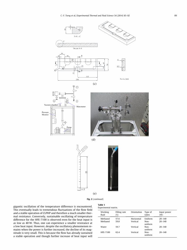
Thermocouples are used to measure the surface and fluid tem-perature. A total of twenty-four T-type thermocouples are placedunderneath the test section for measuring the average surface tem-perature whereas two thermocouples are used to record the inletand outlet temperature of cooling water across the condenser.The schematic of the condenser is shown in Fig. 2(c). The condenseris a cold plate made by copper block (70 mm � 230 mm � 20 mm).In order to minimize the heat loss from the CLPHP to the environ-ment, a U-shaped groove was made by precision machining tolocate the CLPHP. The vacuum, fluid degassing, filling systems areshown in Fig. 2(d) and (e). Firstly, the working fluid is charged intothe filling tube which is attached to the connecting valve (2) asshown in Fig. 2(d). The filling tube and its dimension is shown inFig. 2(e). The degassing of the system is carried out by a rotary vanepump (Alcatel Pascal 2015SD with the vacuum pressure of the sys-tem being lowered to 10�4 torr and remains unchanged for over sixhours). Then the PHP system is connected to (3) shown in Fig. 2(d)with the filling tube for charging the working. Then the workingfluid is charged into the system once the valves connected to (2)and (3) are opened. The locations of the thermocouples on the testsection are as schematically shown in Fig. 2(a). These data signalswere individually recorded and then averaged. During the isother-mal test, the variation of these thermocouples was within 0.2 �C. Inaddition, all the thermocouples were pre-calibrated by a quartzthermometer having 0.01 �C precision. The accuracies of thecalibrated thermocouples are of 0.1 �C. All the data signals arecollected and converted by a data acquisition system (a hybrid re-corder, YOKOGAWA MX-100). The shortest measurement intervalof data acquisition system is 100 ms. The data acquisition systemthen transmitted the converted signals through Ethernet interfaceto the host computer for further operation.
3. Data reduction
The cooling capacity of condenser is calculated from the follow-ing equation:
Qout ¼ _mcpðTw;out � Tw;inÞ ð1Þ

1.Water Bath 2.Pump 3.Filter
4.Flow meter 5.Power Supply
7.Test Section 8.PC
6.Recorder
Fig. 1. Schematic of the experimental setup.
C.-Y. Tseng et al. / Experimental Thermal and Fluid Science 54 (2014) 85–92 87
where _m, cp, Tw,out and Tw,in represent the mass flow rate, specificheat at constant pressure, outlet temperature, and inlet tempera-ture of chilled water, respectively. The total thermal resistance isobtained from the following equation:
R ¼ Te;avg � Tc;avg
Q outð2Þ
where Te,avg and Tc,avg is the average temperature of evaporator andcondenser, and Qout is cooling capacity of condenser. Normally thedifference amid the heat removal from condenser and the suppliedpower is less than 5%.
Uncertainties in the reported experimental values were esti-mated by the method suggested by Moffat [15]. The variables of_m, Te,avg, Tc,avg, Tw,out and Tw,in are used to derive the thermal resis-
tance in Eq. (2). Hence the individual terms are used and combinedby a root-sum-square method to obtain the final thermal resis-tance. The uncertainties range from 5.2% to 18.3% for the coolingcapacity of condenser and are from 7.36% to 18.5% for total thermalresistance. Table 1 denotes a list of all the performed tests in thisstudy, the corresponding experimental conditions such as workingfluids, heat input, filling ratio and orientation are tabulated.
4. Results and discussion
In order to examine the effects of alternating design on the per-formance of CLPHPs, about 60% charge ratio of methanol pertainingto the horizontal orientation was first tested. Test results of thethermal resistance vs. heating power for uniform and alternatingchannels CLPHP are depicted in Fig. 3(a). For the uniform channelCLPHP, the thermal resistance drops considerably provided that
the heating power can stably sustains the circulation of oscillationmotion of the vapor slug within the CLPHP. Thus, a sharp decline ofthe thermal resistance is observed. The results can be made clearfrom the measured surface temperature variation at the evaporatorand condenser as shown in Fig. 3(b) where the corresponding inputpower is 40 W. As seen in the figure, the alternating design revealsconsiderable oscillation of the surface temperatures at the evapo-rator and condenser, suggesting a self-sustaining periodic motionof the vapor slug. On the other hand, the surface temperatures ofthe uniform design remains about the same. Hence, one can seea dramatic difference in thermal resistance between the uniformand alternating design at Qin = 40 W. The thermal resistances ofthe uniform CLPHP are between 0.93 K W�1 and 2.82 K W�1, andthe alternating design can effectively lower the thermal resistanceto 0.325 K W�1. For all input powers, it is found that the thermalresistance of the alternating design is lower than those of uniformdesign. The results are actually associated with the additional un-balanced capillary force for the alternating design as suggested byChien et al. [14]. It is also interesting to know that the thermalresistance is decreased to a minimum value, and followed by amarginal increase. Notice that despite the alternating design canpromote the start-up operation of the CLPHP under horizontalarrangement, the flow circulation caused by the liquid/vapor slugis actually less smooth than that in vertical arrangement. In thissense, without the help of gravity, the generated vapor/liquid slugmotion may easily interact with each other and becomes compar-atively hindered as input power is further increased. As a conse-quence, a small rise of thermal resistance emerges, and this isapplicable for both uniform and alternating design. A theoreticalstudy carried out by Chiang et al. [16] also unveils the same results.

(a)
(b)
Thermocouple
Cooling section
Heating section
3.93mm
1.5mm
Thickness=0.3mm
Thickness=0.3mm
A A B B Section A – A
Section B – B
Fig. 2. Schematic of the test CLPHP and accessory system; (a) dimensions and the locations of the thermocouples; (b) photos of CLPHPs; (c) dimensions of condenser; (d) thevacuum, fluid degassing, and filling system; and (e) filling system. (Unit: mm).
88 C.-Y. Tseng et al. / Experimental Thermal and Fluid Science 54 (2014) 85–92
The foregoing results are applicable for methanol with the hor-izontal arrangement. For further examination of the working fluidson the performance of the CLPHPs. Various working fluids, includ-ing distilled water, methanol and HFE-7100 having a charge ratioof 60% with a vertical upward arrangement was tested andcompared. Test results of the thermal resistance vs. heating powersubject to various working fluids for the alternating design areplotted in Fig. 4. As expected, the thermal resistance decreases con-siderably with the rise of heating power and the thermal resistancein vertical operation is much lower than that of horizontal opera-tion when compared to that in Fig. 3(a). This is expected for the im-posed gravity force appreciably strengthens the circulation of theliquid/vapor slug. Moreover, with the help of gravity force, theengendered motion of the liquid/vapor slug can operate quitesmoothly even at a high input power. As a result, the thermal resis-tance reveals a continuous decline with the heat input. However,
the variation of the thermal resistance against the heat input forthe three working fluids are not the same. As seen in Fig. 4, theHFE-7100 shows the least thermal resistance when the inputpower is less than 60 W, followed by methanol and water. How-ever, the trend is reversed when the heat input is raised above60 W. In fact, the difference of the thermal resistance of water withother fluids shows a more pronounced increase when the power isincreased further. To explain the different characteristics of theworking fluids, the average temperature difference between evap-orator and condenser vs. elapsed time with the heating power of40 W, 100 W and 140 W are plotted in Fig. 5(a) for distilled waterand in Fig. 5(b) for HFE-7100. As clearly seen in Fig. 5(a) for dis-tilled water, apparent ‘start–stop’ of the CLPHP operation is seenfor a heating power being lower than 40 W, suggesting an unsus-tainably oscillatory motion and accordingly a higher thermal resis-tance. On the other hand, with the rise of input power to 140 W,
(c)
(d)
(e)
10
3030
115
15
23
1120
45
70
230
R17
R17
AA
B
B
A-A
C
20
2
R2
C
6.5
4
B-B
PressureMonitor
Pump
Vacuum chamberManometer
Fig. 2 (continued)
Table 1Experimental matrix.
Workingfluid
Filling rate(%)
Orientation Type oftubes
Input power(W)
Methanol 57.6 Horizontal Uniform 20–140Methanol 59.8 Vertical Non-
uniform20–140
Water 59.7 Vertical Non-uniform
20–140
HFE-7100 62.4 Vertical Non-uniform
20–140
C.-Y. Tseng et al. / Experimental Thermal and Fluid Science 54 (2014) 85–92 89
gigantic oscillation of the temperature difference is encountered.This eventually leads to tremendous fluctuations of the flow fieldand a stable operation of CLPHP and therefore a much smaller ther-mal resistance. Conversely, sustainable oscillating of temperaturedifference for the HFE-7100 is observed even for the heat input isas low as 40 W. Thus, one can experience a smaller resistance ata low heat input. However, despite the oscillatory phenomenon re-mains when the power is further increased, the decline of its mag-nitude is very small. This is because the flow has already sustaineda stable operation and though further increase of heat input will

20 40 60 80 100 120 1400.0
0.5
1.0
1.5
2.0
2.5
3.0
R (K
W-1)
Qin (W)
Uniform non-uniform
(a)
0 2 4 6 8 10 12 14 1630
40
50
60
70
80 Tevap - non uniform Tevap - uniform Tcon - non uniform Tcon - uniform
T avg ( °
C)
Time (min)
(b)
Fig. 3. Performance of the CLPHP at horizontal arrangement subject to uniform andalternating design; (a) thermal resistance vs. heating power for uniform andalternating channels CLPHP. (b) Average evaporator and condenser temperature vs.elapsed time for a heating power of 40 W.
0 20 40 60 80 100 120 140 1600.01
0.1
1
10
R (K
W-1)
Qin (W)
Water HFE-7100 Methanol
Fig. 4. Thermal resistance vs. heating power of various working fluids for the CLPHPhaving alternating design and vertical arrangement.
(a)
(b)
0 2 4 6 8 10 12 14 160
5
10
15
20
25
Δ Tav
g ( °C
)
Time (min)
20 W 100 W 140 W
0 2 4 6 8 10 12 14 160
5
10
15
20
25
ΔTav
g(°
C)
Time (min)
20 W 100 W 140 W
Fig. 5. Variation of the average temperature difference of evaporator and condenservs. elapsed time with alternating design having vertical arrangement for(a) distilled water (b) HFE-7100.
0 10 20 30 40 50 60 70 80 90
0
20
40
60
80
100
120
140
160
180
200
P sat (k
Pa)
Temperature (°C)
HFE-7100 Methanol Water
Fig. 6a. Relation of the saturation temperature with temperature subject to variousworking fluids.
90 C.-Y. Tseng et al. / Experimental Thermal and Fluid Science 54 (2014) 85–92
assist the flow circulation but the corresponding viscous drag alsoincrease notably. Therefore further decline of the thermal resis-tance is rather small.

0
500
1000
1500
2000
2500
3000
Viscosity (kg m-1 s
-1)
Specific heat (kJ kg-1 K
-1)
Late
nt h
eat (
kJ k
g-1)
HFE-7100Methonal
Latent heat Specific heat Viscosity
Water
0.0
0.5
1.0
1.5
2.0
2.5
3.0
3.5
4.0
4.5
5.0
0.0
5.0x10⁻⁵
1.0x10⁻⁴
1.5x10⁻⁴
2.0x10⁻⁴
2.5x10⁻⁴
3.0x10⁻⁴
3.5x10⁻⁴
4.0x10⁻⁴
Fig. 6b. Comparison of the thermophysical properties of the various working fluids.
C.-Y. Tseng et al. / Experimental Thermal and Fluid Science 54 (2014) 85–92 91
For a further explanation of the variation of thermal resistancesubject to the various work fluids, (dP/dT)sat of various workingfluids was plotted in Fig. 6a, and the vaporization latent heat, spe-cific heat and viscosity were plotted in Fig. 6b. Explanations of theforegoing results are resorted to the difference at a lower or at ahigher heating power region. Firstly, the key parameter of CLPHPsis to enable sustainably oscillatory flow motion. At a lower heatingpower region, the highest value of (dP/dT)sat of HFE-7100 ensuresthat a small change of evaporator temperature gives rise to a largepressure difference inside the generated bubbles that make way forcontinuous pumping action of the CLPHP. Secondly, Khandekaret al. [7] suggested that a low latent heat may help the formationand deformation of the vapor slug. From Fig. 6b, one can see thatHFE-7100 has the lowest latent heat. Thirdly, the lowest viscosityof HFE-7100 also contributes to a lower frictional pressure drop.In summary of the aforementioned three effects, HFE-7100 showsthe prominent thermal characteristics at a lower heat input(<60 W) due to its easier start-up behavior. On the other hand, ata higher heating power, all of the CLPHPs can be started up withoutdifficulty. In this sense, the thermal property is in control of theoverall performance. Hence the heat transfer of CLPHPs is primarilydue to sensible heat transfer by liquid ad latent transport due toevaporation. Consequently, the lowest specific heat of HFE-7100shown in Fig. 6b will jeopardize the amount of sensible heat trans-fer [5] and its lower latent heat also deteriorates the overall heattransfer characteristics. In summary of the two results, one cansee that water depicts the lowest thermal resistance. Note thatthe thermal resistances of the working fluids show a continuousdrop against heat input. This is because that no apparently dryout is taken place at the present test range.
5. Conclusion
In this study, the performance of closed-loop pulsating heatpipes (CLPHPs) subject to the influence of uniform and alternatingdiameter is reported. The CLPHPs made of copper capillary tubeswith 4 turns and 8 straight sections are used for testing, one ofthe CLPHPs incorporated with a constant tube diameter while theother CLPHP has an alternating tube diameter. The uniform CLPHPis equipped with 2.4 mm ID tube while half of the test tubes of thealternating design is identical to that of the uniform design but therest of the tubes are compressed to an oval-like configuration witha minor diameter being 1.5 mm. The working fluids include
distilled water, methanol and HFE-7100. Tests are performed withboth horizontal and vertical arrangement. Based on the foregoingdiscussions, the following conclusions are made:
(1) For the horizontal arrangement, it is found that the alternat-ing design can be started at a rather low heat input, therebyleading to much smaller thermal resistance when comparedto that of the uniform design. The thermal resistance revealsa sharp decline once the threshold input power is exceeded.Normally the thermal resistance is decreased with the rise ofheat input, and it shows a minimum value at a certain heatinput. However, the thermal resistance shows a marginalrise when the heat input is increased further. Both uniformand alternating design reveals similar trend.
(2) For the vertical arrangement, the thermal resistance is muchlower than that in horizontal arrangement. Unlike those inhorizontal arrangement, the thermal resistance shows a con-tinuous decline against heat input for all the working fluidsprovided that no dry-out occurs.
(3) It is found that the thermal resistance subject to the workingfluids for the CLPHP depends on the input power and work-ing fluids. For a low input power (<60 W), the CLPHP withHFE-7100 can be easily starting up with a sustainable oper-ation, thereby resulting in the least thermal resistance. For ahigh input power, the CLPHP is functional with all the work-ing fluids. In this region, sensible heat along with the latentheat transport plays essential role, therefore distilled waterwith the highest specific heat and latent heat gives thesmallest thermal resistance.
Acknowledgements
The authors are indebted to the financial support from theBureau of Energy of the Ministry of Economic Affairs, Taiwan andgrants from National science council, Taiwan under contractsNSC-100-2221-E-155-066 and NSC-100-2221-E-009-087-MY3.
References
[1] H. Akachi, Structure of a heat pipe, US patent 4921041 (1990).[2] H. Akachi, Structure of micro-heat pipe, US patent 5219020 (1993).[3] S.M. Thompson, H.B. Ma, C. Wilson, Investigation of a flat-plate oscillating heat
pipe with Tesla-type check valves, Exp. Therm. Fluid Sci. 35 (2011) 1265–1273.

92 C.-Y. Tseng et al. / Experimental Thermal and Fluid Science 54 (2014) 85–92
[4] J. Qu, H.Y. Wu, P. Cheng, X. Wang, Non-linear analyses of temperatureoscillations in a closed-loop pulsating heat pipe, Int. J. Heat Mass Transfer 52(2009) 3481–3489.
[5] M.B. Shafii, A. Faghri, Y.W. Zhang, Thermal modeling of unlooped and loopedpulsating heat pipes, J. Heat Transfer 123 (2001) 1159–1172.
[6] S. Khandekar, M. Groll, On the definition of pulsating heat pipes: an overview,in: Proceedings of the 5th Minsk International Seminar (heat pipes, heatpumps and refrigerators), Minsk, Belarus, 2003.
[7] S. Khandekar, N. Dollinger, M. Groll, Understanding operational regimes ofclosed loop pulsating heat pipes: an experimental study, Appl. Therm. Eng. 23(2003) 707–719.
[8] K. Fumoto, M. Kawaji, T. Kawanami, Study on a pulsating heat pipe with self-rewetting fluid, J. Electron. Packaging 132 (3) (2008) 031005.
[9] Y. Vassilev, Y. Avenas, C. Schaeffer, J.L. Schanen, Experimental Study of aPulsating Heat Pipe with Combined Circular and Square Section Channels,Industry Applications Conference, 42nd IAS Annual Meeting., 23–27September 2007, pp. 1419–1425.
[10] N. Kammuang-lue, P. Sakulchangsatjatai, P. Terdtoon, Effect of working fluidson thermal characteristic of a closed-loop pulsating heat pipe heat exchanger:
a case of three heat dissipating devices, in: 2012 IEEE 14th ElectronicsPackaging Technology Conference (EPTC), 5–7 December 2012, pp. 142–147.
[11] M. Groll, S. Khandekar, Pulsating heat pipe: progress and prospects, inProceeding of International Conference on Energy and the EnvironmentConference, 2003, Shanghai, China, 22–24.
[12] J. Qu, Q. Wang, Experimental study on the thermal performance of verticalclosed-loop oscillating heat pipes and correlation modeling, Appl. Energy 112(2013) 1154–1160.
[13] P. Charoensawan, S. Khandekar, M. Groll, P. Terdtoon, Closed loop pulsatingheat pipes – part A: parametric experimental investigations, Appl. Therm. Eng.23 (2003) 2009–2020.
[14] K.H. Chien, Y.T. Lin, Y.R. Chen, K.S. Yang, C.C. Wang, A novel design of pulsatingheat pipe with fewer turns applicable to all orientations, Int. J. Heat MassTransfer 55 (2012) 5722–5728.
[15] R.J. Moffat, Describing the uncertainties in experimental results, Exp. Therm.Fluid Sci. 1 (1988) 3–17.
[16] C.M. Chiang, K.H. Chien, H.M. Chen, C.C. Wang, Theoretical study of oscillatoryphenomena in a horizontal closed-loop pulsating heat pipe with asymmetricalarrayed minichannel, Int. Commun. Heat Mass Transfer 39 (2012) 923–930.