closed loop pulsating heat pipes part b: visualization and
TRANSCRIPT
Applied Thermal Engineering 23 (2003) 2021–2033www.elsevier.com/locate/apthermeng
Closed loop pulsating heat pipesPart B: visualization and semi-empirical modeling
Sameer Khandekar a,*, Piyanun Charoensawan b,Manfred Groll a, Pradit Terdtoon b
a Institut f€uur Kernenergetik und Energiesysteme (IKE), Universit€aat Stuttgart, Pfaffenwaldring 31,
70569 Stuttgart, Germanyb Department of Mechanical Engineering, Chiang Mai University, Chiang Mai 50200, Thailand
Received 4 April 2003; accepted 15 May 2003
Abstract
Pulsating heat pipes have received growing attention from experimental and theoretical researchers inrecent times. Behind its constructional simplicity lie the intriguingly complex thermo-hydrodynamic op-
erational characteristics. Part A of this paper has presented the thermal performance results of a fairly large
matrix of closed loop pulsating heat pipes. This paper, which is an extension of the previous work, first
presents some more visualization results to highlight the complexities involved in mathematical formulation
of the modeling problem. The phenomenological trends recorded in the visualization set-up are fully inline
with the previous quantitative data of Part A. Critical review of the existing modeling approaches to
CLPHPs is presented in the wake of these results. A detailed discussion follows on the important issues
involved in the mathematical modeling of these devices. Then, semi-empirical correlations based on non-dimensional numbers of interest for predicting the thermal performance of CLPHPs are presented. Al-
though there are limitations of the models presented herein, modeling by non-dimensional numbers seems
to be most promising as compared to other existing techniques.
� 2003 Elsevier Ltd. All rights reserved.
Keywords: Pulsating heat pipe; Semi-empirical correlation
* Corresponding author. Tel.: +49-711-685-2142; fax: +49-711-685-2010.
E-mail address: [email protected] (S. Khandekar).
1359-4311/$ - see front matter � 2003 Elsevier Ltd. All rights reserved.doi:10.1016/S1359-4311(03)00168-6

Nomenclature
Bo Bond NumberCp constant pressure specific heat, J/kgKD tube diameter, mE€oo E€ootv€oos Numberf friction factorg gravitational acceleration, m/s2
h heat transfer coefficient, W/m2 Khfg latent heat, J/kgJa Jakob numberKa Karman numberk thermal conductivity, W/mKL length, m_mm mass flow rate, kg/sN number of turnsP pressure, N/m2
Pr Prandtl number_QQ heat transfer rate, W_qq heat flux, W/m2
Re Reynolds numberT temperature, �C or Kt� characteristic velocity m/sx� two-phase mass quality
Greek symbolsb inclination angle from horizontal axis, radianl dynamic viscosity, Pa sq density, kg/m3
r surface tension, N/m
Subscripts
a adiabatic sectionc condenser sectionCB convective boilingcrit critical valuee evaporator sectionexp experimenti innerl liquidNB nucleate boilingo outerpre predictedsat saturation conditionv vapor
2022 S. Khandekar et al. / Applied Thermal Engineering 23 (2003) 2021–2033

S. Khandekar et al. / Applied Thermal Engineering 23 (2003) 2021–2033 2023
1. Introduction
A modest number of studies, mostly qualitative and some quantitative, have been performed sofar to understand the thermo-hydrodynamics of pulsating heat pipes (e.g. [1–4]). Various oper-ational characteristics, parametric experiments and phenomenological studies have indicated thatthis family of heat pipes is extremely complex from many aspects of thermo-fluidic sciences.Although important milestones have been achieved in specific areas, a comprehensive under-standing is still lacking. Parallel research is also underway in the direction of mathematicalmodeling of pulsating heat pipes. Looking at the available literature it can be concluded thatsuccess in this direction is only marginal. Many simplified approaches have been attempted whichmay be categorized according to the simplification scheme adopted. These may be summarized as:Type 1: comparing PHP action to equivalent single spring-mass-damper system [5], Type II: ki-nematic analysis by comparison with a multiple spring-mass-damper system [6], Type III: ap-plying conservation equations of mass, momentum and energy to specified slug–plug controlvolume [7,8], Type IV: analysis highlighting the existence of chaos under some operating condi-tions [9] and Type V: modeling based on Artificial Neural Networks, wherein an ANN archi-tecture is trained to predict performance with the available experimental database [10]. Extremesimplification has been adopted in all the above approaches and the results have only limitedvalidity and contribution in overall understanding of the device, not to mention in performanceprediction and optimization [11].In the present work, firstly the general strategy of mathematical modeling of closed loop pul-
sating heat pipes is discussed taking into consideration the experimental evidences available so far.Then a semi-empirical modeling scheme incorporating non-dimensional numbers of interest ispresented. The non-dimensional numbers affecting the thermo-fluidic behavior are identified andtheir direction of influence is explained. The experimental data presented in Part A of this paper isused to construct the model [12]. In addition, apart from drawing information from other visu-alization studies, glass tube transparent CLPHP structures are fabricated to augment the quan-titative results. The visualization trends clearly indicate the strong dependence of the thermalperformance of CLPHPs on the flow patterns existing in the device. Based on the results of thepresent study and the discussion of the issues related to mathematical modeling of pulsating heatpipes provided before the background of the visualization results, it seems that semi-empiricalapproaches may prove to be the most promising in modeling CLPHPs amongst all the existingtechniques applied so far.
2. Experimental set-up (for flow visualization)
In Part A of this paper, the experimental set-up and plan was outlined for the quantitativemeasurements performed on CLPHPs made of copper tubes [12]. To augment the understandingof these quantitative results, visualization experiments were planned. These were deemed neces-sary in view of the already existing hypothesis that the thermal performance (e.g. the overallthermal resistance) is largely dependent on the two-phase flow patterns existing in the device. Thevisualization experiments have indeed proven this hypothesis as will be demonstrated in theresults.
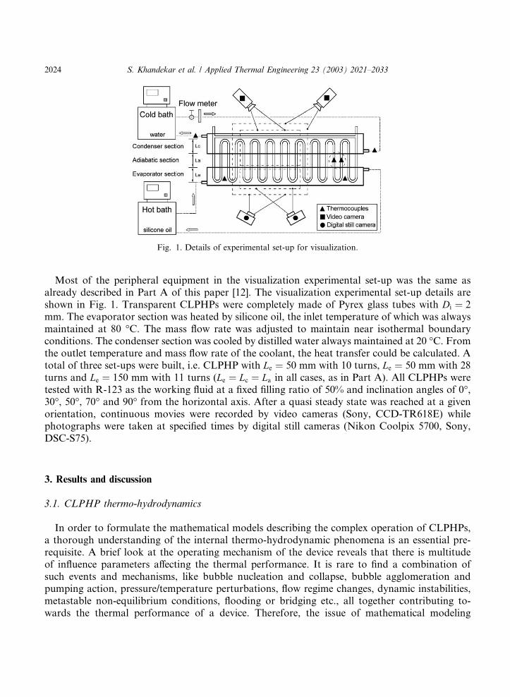
Fig. 1. Details of experimental set-up for visualization.
2024 S. Khandekar et al. / Applied Thermal Engineering 23 (2003) 2021–2033
Most of the peripheral equipment in the visualization experimental set-up was the same asalready described in Part A of this paper [12]. The visualization experimental set-up details areshown in Fig. 1. Transparent CLPHPs were completely made of Pyrex glass tubes with Di ¼ 2mm. The evaporator section was heated by silicone oil, the inlet temperature of which was alwaysmaintained at 80 �C. The mass flow rate was adjusted to maintain near isothermal boundaryconditions. The condenser section was cooled by distilled water always maintained at 20 �C. Fromthe outlet temperature and mass flow rate of the coolant, the heat transfer could be calculated. Atotal of three set-ups were built, i.e. CLPHP with Le ¼ 50 mm with 10 turns, Le ¼ 50 mm with 28turns and Le ¼ 150 mm with 11 turns (Le ¼ Lc ¼ La in all cases, as in Part A). All CLPHPs weretested with R-123 as the working fluid at a fixed filling ratio of 50% and inclination angles of 0�,30�, 50�, 70� and 90� from the horizontal axis. After a quasi steady state was reached at a givenorientation, continuous movies were recorded by video cameras (Sony, CCD-TR618E) whilephotographs were taken at specified times by digital still cameras (Nikon Coolpix 5700, Sony,DSC-S75).
3. Results and discussion
3.1. CLPHP thermo-hydrodynamics
In order to formulate the mathematical models describing the complex operation of CLPHPs,a thorough understanding of the internal thermo-hydrodynamic phenomena is an essential pre-requisite. A brief look at the operating mechanism of the device reveals that there is multitudeof influence parameters affecting the thermal performance. It is rare to find a combination ofsuch events and mechanisms, like bubble nucleation and collapse, bubble agglomeration andpumping action, pressure/temperature perturbations, flow regime changes, dynamic instabilities,metastable non-equilibrium conditions, flooding or bridging etc., all together contributing to-wards the thermal performance of a device. Therefore, the issue of mathematical modeling
S. Khandekar et al. / Applied Thermal Engineering 23 (2003) 2021–2033 2025
of CLPHPs has to be dealt with only in the background of the established experimental evi-dences.Although the internal fluid flow pattern has been classified, in general, as capillary slug flow,
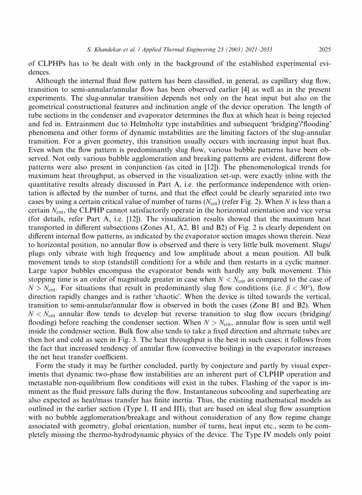
transition to semi-annular/annular flow has been observed earlier [4] as well as in the presentexperiments. The slug-annular transition depends not only on the heat input but also on thegeometrical constructional features and inclination angle of the device operation. The length oftube sections in the condenser and evaporator determines the flux at which heat is being rejectedand fed in. Entrainment due to Helmholtz type instabilities and subsequent �bridging�/�flooding�phenomena and other forms of dynamic instabilities are the limiting factors of the slug-annulartransition. For a given geometry, this transition usually occurs with increasing input heat flux.Even when the flow pattern is predominantly slug flow, various bubble patterns have been ob-served. Not only various bubble agglomeration and breaking patterns are evident, different flowpatterns were also present in conjunction (as cited in [12]). The phenomenological trends formaximum heat throughput, as observed in the visualization set-up, were exactly inline with thequantitative results already discussed in Part A, i.e. the performance independence with orien-tation is affected by the number of turns, and that the effect could be clearly separated into twocases by using a certain critical value of number of turns (Ncrit) (refer Fig. 2). When N is less than acertain Ncrit, the CLPHP cannot satisfactorily operate in the horizontal orientation and vice versa(for details, refer Part A, i.e. [12]). The visualization results showed that the maximum heattransported in different subsections (Zones A1, A2, B1 and B2) of Fig. 2 is clearly dependent ondifferent internal flow patterns, as indicated by the evaporator section images shown therein. Nearto horizontal position, no annular flow is observed and there is very little bulk movement. Slugs/plugs only vibrate with high frequency and low amplitude about a mean position. All bulkmovement tends to stop (standstill condition) for a while and then restarts in a cyclic manner.Large vapor bubbles encompass the evaporator bends with hardly any bulk movement. Thisstopping time is an order of magnitude greater in case when N < Ncrit as compared to the case ofN > Ncrit. For situations that result in predominantly slug flow conditions (i.e. b < 30�), flowdirection rapidly changes and is rather �chaotic�. When the device is tilted towards the vertical,transition to semi-annular/annular flow is observed in both the cases (Zone B1 and B2). WhenN < Ncrit annular flow tends to develop but reverse transition to slug flow occurs (bridging/flooding) before reaching the condenser section. When N > Ncrit, annular flow is seen until wellinside the condenser section. Bulk flow also tends to take a fixed direction and alternate tubes arethen hot and cold as seen in Fig. 3. The heat throughput is the best in such cases; it follows fromthe fact that increased tendency of annular flow (convective boiling) in the evaporator increasesthe net heat transfer coefficient.Form the study it may be further concluded, partly by conjecture and partly by visual exper-
iments that dynamic two-phase flow instabilities are an inherent part of CLPHP operation andmetastable non-equilibrium flow conditions will exist in the tubes. Flashing of the vapor is im-minent as the fluid pressure falls during the flow. Instantaneous subcooling and superheating arealso expected as heat/mass transfer has finite inertia. Thus, the existing mathematical models asoutlined in the earlier section (Type I, II and III), that are based on ideal slug flow assumptionwith no bubble agglomeration/breakage and without consideration of any flow regime changeassociated with geometry, global orientation, number of turns, heat input etc., seem to be com-pletely missing the thermo-hydrodynamic physics of the device. The Type IV models only point
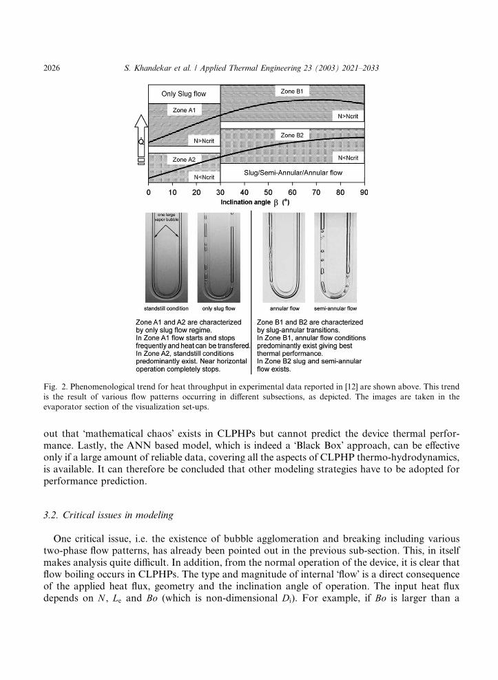
Fig. 2. Phenomenological trend for heat throughput in experimental data reported in [12] are shown above. This trend
is the result of various flow patterns occurring in different subsections, as depicted. The images are taken in the
evaporator section of the visualization set-ups.
2026 S. Khandekar et al. / Applied Thermal Engineering 23 (2003) 2021–2033
out that �mathematical chaos� exists in CLPHPs but cannot predict the device thermal perfor-mance. Lastly, the ANN based model, which is indeed a �Black Box� approach, can be effectiveonly if a large amount of reliable data, covering all the aspects of CLPHP thermo-hydrodynamics,is available. It can therefore be concluded that other modeling strategies have to be adopted forperformance prediction.
3.2. Critical issues in modeling
One critical issue, i.e. the existence of bubble agglomeration and breaking including varioustwo-phase flow patterns, has already been pointed out in the previous sub-section. This, in itselfmakes analysis quite difficult. In addition, from the normal operation of the device, it is clear thatflow boiling occurs in CLPHPs. The type and magnitude of internal �flow� is a direct consequenceof the applied heat flux, geometry and the inclination angle of operation. The input heat fluxdepends on N , Le and Bo (which is non-dimensional Di). For example, if Bo is larger than a
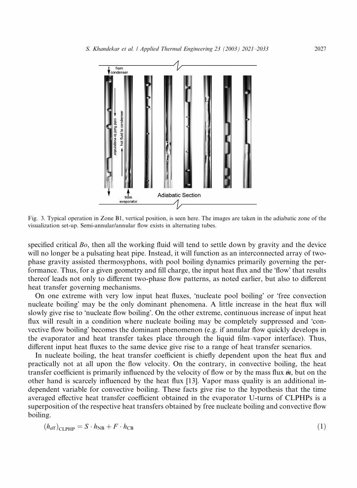
Fig. 3. Typical operation in Zone B1, vertical position, is seen here. The images are taken in the adiabatic zone of the
visualization set-up. Semi-annular/annular flow exists in alternating tubes.
S. Khandekar et al. / Applied Thermal Engineering 23 (2003) 2021–2033 2027
specified critical Bo, then all the working fluid will tend to settle down by gravity and the devicewill no longer be a pulsating heat pipe. Instead, it will function as an interconnected array of two-phase gravity assisted thermosyphons, with pool boiling dynamics primarily governing the per-formance. Thus, for a given geometry and fill charge, the input heat flux and the �flow� that resultsthereof leads not only to different two-phase flow patterns, as noted earlier, but also to differentheat transfer governing mechanisms.On one extreme with very low input heat fluxes, �nucleate pool boiling� or �free convection
nucleate boiling� may be the only dominant phenomena. A little increase in the heat flux willslowly give rise to �nucleate flow boiling�. On the other extreme, continuous increase of input heatflux will result in a condition where nucleate boiling may be completely suppressed and �con-vective flow boiling� becomes the dominant phenomenon (e.g. if annular flow quickly develops inthe evaporator and heat transfer takes place through the liquid film–vapor interface). Thus,different input heat fluxes to the same device give rise to a range of heat transfer scenarios.In nucleate boiling, the heat transfer coefficient is chiefly dependent upon the heat flux and
practically not at all upon the flow velocity. On the contrary, in convective boiling, the heattransfer coefficient is primarily influenced by the velocity of flow or by the mass flux _mm, but on theother hand is scarcely influenced by the heat flux [13]. Vapor mass quality is an additional in-dependent variable for convective boiling. These facts give rise to the hypothesis that the timeaveraged effective heat transfer coefficient obtained in the evaporator U-turns of CLPHPs is asuperposition of the respective heat transfers obtained by free nucleate boiling and convective flowboiling.
ðheffÞCLPHP ¼ S � hNB þ F � hCB ð1Þ

2028 S. Khandekar et al. / Applied Thermal Engineering 23 (2003) 2021–2033
The quantities S and F are essentially adjustment parameters (also referred to as �suppression� or�enhancement� factors [14]) to take into account the relative importance of nucleate pool boilingand convective flow boiling mechanisms. Such a hypothesis is also adopted frequently in modelingusual convective flow boiling in open systems. In open systems, the basic empirical correlationsfor modeling hNB are of the form,
hNB / C1 � _qqn ð2Þ
More detailed and well known models prescribed for hNB by Rohsenow [15] and Forsterand Zuber [16] are based on the assumption that the process of bubble growth and release in-duces motions of the surrounding liquid that facilitates convective transport of the heat fromthe adjacent surface. This hypothesis leads to the following generic form of models describinghNB,
ðNuÞNB ¼hNB � L�
kliq
� �¼ C � ðRe�Þn � ðPrliqÞm ð3Þ
In this equation the characteristic length and velocity scales (L� and Re�) are appropriately selectedas per the situation (e.g. bubble departure diameter and vapor superficial velocity). It is interestingto note that by such an appropriate substitution, these Nusselt–Reynolds number correlations canbe reduced to forms quite similar to Eq. (2) above. The success of these equations lies in the factthat it has been possible to explicitly deduce characteristic length and velocity scales form thethermo-mechanical boundary conditions of the problem.For modeling hCB in open systems, additional effects of the mass flux _mm and two phase flow
quality x� must be included so that the equation takes the form,
hCB / C1 � _qqn � ð _mmÞs � Uðx�Þ ð4Þ
where the quantity C1 is a strong function of the heated surface and the properties of the boilingliquid. In this case too, the characteristic liquid velocity scale is known a priori as the mass fluxand geometry are specified in the open system.Major hurdles in practical realization of Eq. (1) for design purposes in case of CLPHPs are as
follows:
• The system is closed.• The characteristic velocity scale is not explicitly known. It strongly depends on the input heatflux and other geometrical constructional features of the device. In addition, the �flow velocity�has an oscillating character.
• In general, there is not enough quantitative flow and heat transfer data available on two-phaseopen systems in mini-micro channels. More data and subsequent understanding is required onflow instabilities, pulsating and oscillating flows in mini-micro capillary tube systems and re-lated issues. Data on CLPHPs is still more scarce.
Thus, it may be concluded that there are several complex inter-related issues that distinguishmathematical modeling of CLPHPs from conventional modeling of flow boiling in open systems.

S. Khandekar et al. / Applied Thermal Engineering 23 (2003) 2021–2033 2029
3.3. Non-dimensional groups of interest
In order to find heat transfer correlations having broad applicability range, it is generallyconvenient to state the decisive thermo-physical properties for heat transfer as non-dimensionalquantities. This proposal is a direct and natural consequence of foregoing discussion on thecritical issues involved in modeling of CLPHPs. In addition, an exponential form of the corre-lation is preferable since such equations are well proven for heat transfer phenomena. From thequantitative investigations of CLPHPs presented in Part A and in conjunction with the internalflow patterns described herein, it can be concluded that the influence parameters consist of theinclination angle (b), the thermo-physical properties of working fluid, the tube inner diameter (Di),the number of turns (N ) and the evaporator length (Le) as defined by the following equation,
_qq ¼_QQ
p � Di � N � 2Le
!
¼ Uðb; geometry; thermo-physical properties of working fluidÞ ð5Þ
Since the experiments were conducted at a fixed filling ratio of 50% of the working fluid, thisparameter does not appear in the above equation. For a more generalized case, the effect of fillingratio also has to be included. The identification of the important non-dimensional groups whichaffect the heat transfer characteristics of the device and the proper definition of the function U isneeded for practical exploitation of Eq. (5).Before proceeding further, it should be pointed out that, in general, experiments on CLPHPs
may be performed in two ways (i) either by controlling the input heat flux and the condensertemperature; in this case the evaporator temperature is the dependent parameter, or (ii) bycontrolling the evaporator and condenser temperatures (DT e�csat ); the heat throughput then be-comes the dependent variable. The experiments reported in Part A were done with the latterstrategy. In doing so, the maximum temperature difference occurring in the device was fixed andthis, in turn, gave the corresponding saturation pressure difference (DP e�csat ).The equations stated in the previous section already provide a broad hint of the important non-
dimensional quantities of interest. It is indeed obvious that some representative form of flowReynolds number affects the heat transfer. As noted earlier, it is essential to find the characteristicvelocity scale as per the boundary conditions of the problem. Since the experiments reported inPart A were done by maintaining the evaporator and condenser temperature constant (i.e. DT e�csatconstant), the characteristic Reynolds number may be calculated as follows:
Reliq ¼qliq � t� � Di
lliq
!ð6Þ
and since the pressure drop in pipe flows is given by
ðDP Þliq /f � ðqliq � ðt�Þ
2ÞðDi=LeffÞ
ð7Þ
substituting Eq. (7) into Eq. (6) defines a dimensional group, sometimes referred to as Karmannumber in the context of pipe flows:
2030 S. Khandekar et al. / Applied Thermal Engineering 23 (2003) 2021–2033
Kaliq ¼ f � Re2liq ¼qliq � ðDP Þliq � D2i
l2liq � Leffwhere Leff ¼ 0:5ðLe þ LcÞ þ La ð8Þ
The fact that Karman number is calculated for the liquid phase (and not for an equivalent ho-mogeneous two-phase mixture) is based on the assumption that out of the total fluid losses,consisting of ðDP Þliq and ðDP Þvap, the former is an order of magnitude higher than the latter.Therefore, in the above Eq. (8), ðDP Þliq ðDPÞe�csat . Thus, the Karman number gives an appropriatevelocity scale for CLPHP modeling.The next numbers of interest, which do not need explanation, are the liquid Prandtl number
and the Jakob number, defined respectively as,
Prliq ¼Cp;liq � lliq
kliq
� �ð9Þ
Ja ¼ hfgCp;liq � ðDT Þe�csat
� �ð10Þ
the thermo-physical properties being calculated at ðTe þ TcÞ=2. The liquid Prandtl number scalesthe single phase convective effect on heat transfer while the Jakob number highlights the relativeimportance of sensible and latent portions of heat transfer in a CLPHP. In addition, from thegeneric trends of the experimental data reported in Part A, an exponential function was found tobe the best representation of the effect of inclination angle. Thus, Eq. (5) can be written as,
_qq ¼_QQ
p � Di � N � ð2LeÞ
!¼ C1 � ðexpðbÞÞp � Kaqliq � Prrliq � Jas ð11Þ
In the above equation the constant C1 has the dimension of W/m2.The Bond number (or alternatively the E€ootv€oos number) is the ratio of surface tension and
gravity forces and defined as follows,
Bo ¼ Diffiffiffiffiffiffiffiffiffiffiffiffiffiffiffiffiffiffiffiffiffiffiffiffiffiffiffiffiffiffiffiffigðqliq � qvapÞ=r
q¼
ffiffiffiffiffiffiE€oo
pð12Þ
If the Bond number exceeds a particular critically value (Bocrit 2) stable liquid slugs will notform and the device will not function as a pulsating heat pipe, as explained in Part A of this paper[12]. For Bo > 2 (for example standard closed two-phase thermosyphons), the heat transferlimitation comes from nucleate pool boiling and counter-current flow limitations [17–19]. Basedon these facts it may be said, although without existence of evidence, in favor or otherwise, thatEq. (11) is only valid for situations where Bo6Bocrit.An attempt was made to correlate the entire data sets (a total of 248 data) of the experimental
matrix reported in Part A [12]. This resulted in a correlation given by Eq. (13) below for which thefit is depicted graphically in Fig. 4. Standard least square curve fitting technique coupled withGauss elimination method was adopted resulting in an overall drift in predictions within �30%.
_qq ¼_QQ
pDi � N � 2Le
!¼ 0:54ðexpðbÞÞ0:48Ka0:47 Pr0:27liq Ja1:43N�0:27 ð13Þ
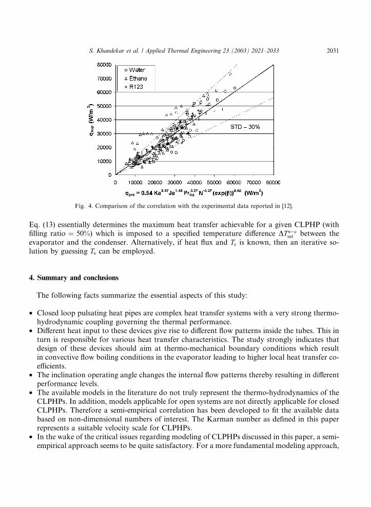
Fig. 4. Comparison of the correlation with the experimental data reported in [12].
S. Khandekar et al. / Applied Thermal Engineering 23 (2003) 2021–2033 2031
Eq. (13) essentially determines the maximum heat transfer achievable for a given CLPHP (withfilling ratio ¼ 50%) which is imposed to a specified temperature difference DT e�csat between theevaporator and the condenser. Alternatively, if heat flux and Tc is known, then an iterative so-lution by guessing Te can be employed.
4. Summary and conclusions
The following facts summarize the essential aspects of this study:
• Closed loop pulsating heat pipes are complex heat transfer systems with a very strong thermo-hydrodynamic coupling governing the thermal performance.
• Different heat input to these devices give rise to different flow patterns inside the tubes. This inturn is responsible for various heat transfer characteristics. The study strongly indicates thatdesign of these devices should aim at thermo-mechanical boundary conditions which resultin convective flow boiling conditions in the evaporator leading to higher local heat transfer co-efficients.
• The inclination operating angle changes the internal flow patterns thereby resulting in differentperformance levels.
• The available models in the literature do not truly represent the thermo-hydrodynamics of theCLPHPs. In addition, models applicable for open systems are not directly applicable for closedCLPHPs. Therefore a semi-empirical correlation has been developed to fit the available databased on non-dimensional numbers of interest. The Karman number as defined in this paperrepresents a suitable velocity scale for CLPHPs.
• In the wake of the critical issues regarding modeling of CLPHPs discussed in this paper, a semi-empirical approach seems to be quite satisfactory. For a more fundamental modeling approach,
2032 S. Khandekar et al. / Applied Thermal Engineering 23 (2003) 2021–2033
an additional reliable data base is needed in congruence to the wider research in mini/microscale boiling heat transfer in open systems.
Acknowledgements
This research work was done jointly by Faculty of Engineering, Chiang Mai University,Thailand and Institut f€uur Kernenergetik und Energiesysteme (IKE), Universit€aat Stuttgart, Ger-many under the auspices of Royal Golden Jubilee Scholarship of the Thailand Research Fund(under contract no.: 1.M.CM/43/A.1) and Deutscher Akademischer Austauschdienst (DAAD).The work was also partly supported by Deutsche Forschungsgemeinschaft (DFG) under GrantGR-412/33-1.
References
[1] H. Akachi, F. Pol�aa�ssek, Thermal control of IGBT modules in traction drives by pulsating heat pipes, in:Proceedings of 10th International Heat Pipe Conference, vol. 3, Stuttgart, 1997, pp. 8–12.
[2] M. Hosoda, S. Nishio, R. Shirakashi, Study of meandering closed-loop heat-transport device (vapour-plug
propagation phenomena), JSME Int. J. B 42/4 (1999) 737–744.
[3] S. Khandekar, M. Schneider, P. Sch€aafer, R. Kulenovic, M. Groll, Thermofluiddynamic study of flat plate closedloop pulsating heat pipes, in: Microscale Thermophysical Engineering, vol. 6(4), Taylor and Francis, ISSN 1089-
3954, 2002, pp. 303–318.
[4] M. Groll, S. Khandekar, Pulsating heat pipes: progress and prospects, in: Proceedings of 3rd International
Conference on Energy and Environment, Shanghai, 2003, in press.
[5] Z. Zuo, M. North, Miniature High Heat Flux Heat Pipes for Cooling of Electronics, Thermacore Inc., 2000,
Available at www.thermacore.com.
[6] T. Wong, B. Tong, S. Lim, K. Ooi, Theoretical modeling of pulsating heat pipe, in: Proceedings of 11th
Interantional Heat Pipe Conference, Tokyo, 1999, pp. 159–163.
[7] G. Swanepoel, A. Taylor, R. Dobson, Theoretical modeling of pulsating heat pipes, in: Proceedings of 6th
International Heat Pipe Symposium, Chiang Mai, 2000.
[8] M. Shafii, A. Faghri, Y. Zhang, Thermal modeling of unlooped and looped pulsating heat pipes, J. Heat Transfer,
ASME 123 (2001) 1159–1172.
[9] S. Maezawa, S. Nakajima, K. Gi, H. Akachi, Experimental study on chaotic behavior of thermohydraulic
oscillation in oscillating thermosyphon, Heat Pipe Technology (Proceedings of 5th International Heat Pipe
Symposium), Pergamon Elsevier, ISBN 0-08-042842-8, Melbourn, 1996, pp. 131–137.
[10] S. Khandekar, X. Cui, M. Groll, Thermal performance modeling of pulsating heat pipes by artificial neural
network, in: Proceedings of 12th International Heat Pipe Conference, Moscow, 2002, pp. 215–219.
[11] S. Khandekar, M. Schneider, M. Groll, Mathematical modeling of pulsating heat pipes: state of the art and future
challenges, in: Proceedings of 5th ASME/ISHMT Joint International Heat and Mass Transfer Conference, Tata
McGraw Hill, ISBN-0-07-047443-5, Kolkata, 2002, pp. 856–862.
[12] P. Charoensawan, S. Khandekar, M. Groll, P. Terdtoon, Closed loop pulsating heat pipes––Part A: Parametric
experimental investigations, Applied Thermal Engineering, Elsevier Science, ISSN 1359-4311, in press, 2003.
[13] K. Stephan, Heat Transfer in Condensation and Boiling, ISBN 0-387-52203-4, Springer Verlag, 1992.
[14] J. Chen, Correlation for boiling heat transfer to saturated liquids in convective flow, Ind. Engng. Chem. Prog. Des.
Dev. 5 (1966) 322–329.
[15] W. Rohsenow, A method for correlating heat transfer data for surface boiling of liquids, Trans. ASME, J. Heat
Transfer 74 (1952) 969–976.
[16] H. Forster, N. Zuber, Dynamics of vapor bubbles and boiling heat transfer, AIChE 1 (1955) 531–535.

S. Khandekar et al. / Applied Thermal Engineering 23 (2003) 2021–2033 2033
[17] S. Kutateladze, Elements of hydrodynamics of gas–liquid systems, Fluid Mech.––Sov. Res. 1 (1972) 29–50.
[18] C. Tien, K. Chung, Entrainment limits in heat pipes, in: Proceedings of 3rd International Heat Pipe Conference,
Palo Alto (CA), 1978, pp. 36–40.
[19] M. Groll, S. R€oosler, Operation principles and performance of heat pipes and closed two-phase thermosyphons,J. Non-Equil. Thermody. 17 (1992) 91–151.