effect of nanofluids on thermal performance of closed loop pulsating heat pipe
TRANSCRIPT
Experimental Thermal and Fluid Science 54 (2014) 171–178
Contents lists available at ScienceDirect
Experimental Thermal and Fluid Science
journal homepage: www.elsevier .com/locate /et fs
Effect of nanofluids on thermal performance of closed loop pulsatingheat pipe
http://dx.doi.org/10.1016/j.expthermflusci.2014.02.0070894-1777/� 2014 Elsevier Inc. All rights reserved.
⇑ Corresponding author. Tel.: +91 422 2614439.E-mail address: [email protected] (V.K. Karthikeyan).
V.K. Karthikeyan a,⇑, K. Ramachandran b, B.C. Pillai a, A. Brusly Solomon a
a Centre for Research in Material Science & Thermal Management, Karunya University, Coimbatore 641114, Indiab Department of Physics, Bharathiar University, Coimbatore 641046, India
a r t i c l e i n f o a b s t r a c t
Article history:Received 29 July 2013Received in revised form 9 January 2014Accepted 5 February 2014Available online 12 February 2014
Keywords:Closed loop pulsating heat pipeNanofluidsScanning Electron MicroscopeThermal performance
The paper describes the effect of nanofluids on the closed loop pulsating heat pipe (CLPHP) performanceusing copper and silver colloidal nanofluids. An experimental program has been carried out on the ther-mal performance of the CLPHP with different working fluids (DI water, copper and silver colloidal nano-fluids). Copper nanoparticles are characterized by the X-ray diffraction and Scanning ElectronMicroscope. Copper nanofluid is prepared by a two step method and distribution of nanoparticles is jus-tified by using Dynamic Light Scattering technique. Another nanofluid i.e., silver colloidal nanofluid solu-tion is synthesized using chemical reduction method and characterized using UV–vis AbsorptionSpectroscopy and Dynamic Light Scattering techniques. The thermal performance of the device has beeninvestigated with varying heat power in the range of 50–240 W for different working fluids in the verticalorientation. The overall thermal resistance and effective thermal conductivity are evaluated to predict thethermal performance of the device. Experimental results show that the nanofluid charged CLPHPsenhance the heat transfer limit by 33.3% and have lower evaporator wall temperature compared to thatof DI water. The intensifying nucleation sites are found in the inner tube of the evaporator section due tousage of nanofluid in the CLPHP. The device with nanofluids achieves better thermal performance as com-pared to that of DI water. Furthermore, a preliminary visual study is carried out to understand the deviceoperation with copper nanofluid in the glass tube CLPHP. Several important features of CLPHP operationare delineated by the visualization.
� 2014 Elsevier Inc. All rights reserved.
1. Introduction
Pulsating heat pipe/oscillating heat pipe (PHP) is a passive twophase heat transfer device, which is a special category of wicklessheat pipes. It has been invented by Akachi [1–3], it exhibits self-sustained oscillation of the working fluid and phase change phe-nomenon leading to enhanced heat transfer. Due to its simple de-sign, light weight, low fabrication cost and very fast response athigher heat loads, PHPs have been considered as one of the com-pact heat transfer devices for various cooling applications such aselectronics cooling, heat exchanger and space application, etc.Since the last two decades, many researchers [4–12] have investi-gated its thermal performance experimentally and theoretically.These experiments reveal that the CLPHP performance is stronglyaffected by many parameters including geometrical, physical andoperational parameters. Furthermore, it is mentioned that theproblem of two phase flow oscillation in closed loop pulsating heat
pipe is very complicated because of many unstable variables andcomplexity of thermo-hydrodynamic operational characteristics.In the meantime, some visual studies [10–12] have been per-formed using glass tube to understand the operational behaviorand considerable progress has been also achieved in theseattempts.
In recent years, improving thermal performance of CLPHP hasbecome a demanding challenge and hot research topic due to rap-idly increasing heat load and miniaturization of electronic devices.Based on existing experimental results [4–9], the working fluid isthe most important parameter in the CLPHP. At the same time,nanofluids are viewed as advanced heat transfer fluids in heattransfer devices. In general, the nanoparticles suspended in thebase fluid forming the nanofluid are of size about less than100 nm. The heat transfer performance of the base fluid is signifi-cantly improved due to increased surface area. In 1995, this con-cept was first proposed by Choi [13]. Since then, someresearchers [13–16] have focused on the heat transfer characteris-tics of nanofluids such as thermal conductivity and viscosity in sin-gle phase flow and also flow with phase change.
Nomenclature
A area (m2)Cp specific heat of liquid (J/kg K)d diameter (m)K thermal conductivity (W/m�C)DK change in thermal conductivity (W/m�C)L length (m)_m mass flow rate (kg/s)
n number of parallel channels (–)P electrical power (W)Q heat power (W)DQ change in heat power (W)R thermal resistance (�C/W)DR change in thermal resistance (�C/W)T temperature (�C)DT temperature difference (�C)
Subscriptsa adiabaticavg averagec condensercr cross sectione evaporatoreff effectivei inleto outletout outerover overalltot totalw water1 cooling medium temperature
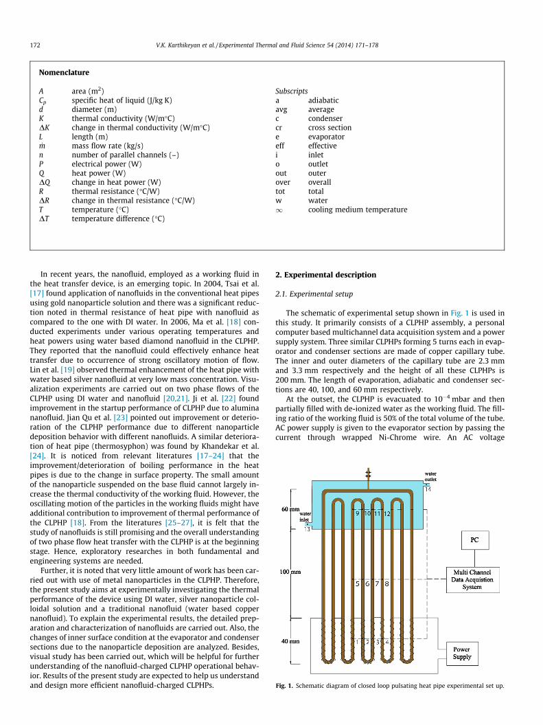
Fig. 1. Schematic diagram of closed loop pulsating heat pipe experimental set up.
172 V.K. Karthikeyan et al. / Experimental Thermal and Fluid Science 54 (2014) 171–178
In recent years, the nanofluid, employed as a working fluid inthe heat transfer device, is an emerging topic. In 2004, Tsai et al.[17] found application of nanofluids in the conventional heat pipesusing gold nanoparticle solution and there was a significant reduc-tion noted in thermal resistance of heat pipe with nanofluid ascompared to the one with DI water. In 2006, Ma et al. [18] con-ducted experiments under various operating temperatures andheat powers using water based diamond nanofluid in the CLPHP.They reported that the nanofluid could effectively enhance heattransfer due to occurrence of strong oscillatory motion of flow.Lin et al. [19] observed thermal enhancement of the heat pipe withwater based silver nanofluid at very low mass concentration. Visu-alization experiments are carried out on two phase flows of theCLPHP using DI water and nanofluid [20,21]. Ji et al. [22] foundimprovement in the startup performance of CLPHP due to aluminananofluid. Jian Qu et al. [23] pointed out improvement or deterio-ration of the CLPHP performance due to different nanoparticledeposition behavior with different nanofluids. A similar deteriora-tion of heat pipe (thermosyphon) was found by Khandekar et al.[24]. It is noticed from relevant literatures [17–24] that theimprovement/deterioration of boiling performance in the heatpipes is due to the change in surface property. The small amountof the nanoparticle suspended on the base fluid cannot largely in-crease the thermal conductivity of the working fluid. However, theoscillating motion of the particles in the working fluids might haveadditional contribution to improvement of thermal performance ofthe CLPHP [18]. From the literatures [25–27], it is felt that thestudy of nanofluids is still promising and the overall understandingof two phase flow heat transfer with the CLPHP is at the beginningstage. Hence, exploratory researches in both fundamental andengineering systems are needed.
Further, it is noted that very little amount of work has been car-ried out with use of metal nanoparticles in the CLPHP. Therefore,the present study aims at experimentally investigating the thermalperformance of the device using DI water, silver nanoparticle col-loidal solution and a traditional nanofluid (water based coppernanofluid). To explain the experimental results, the detailed prep-aration and characterization of nanofluids are carried out. Also, thechanges of inner surface condition at the evaporator and condensersections due to the nanoparticle deposition are analyzed. Besides,visual study has been carried out, which will be helpful for furtherunderstanding of the nanofluid-charged CLPHP operational behav-ior. Results of the present study are expected to help us understandand design more efficient nanofluid-charged CLPHPs.
2. Experimental description
2.1. Experimental setup
The schematic of experimental setup shown in Fig. 1 is used inthis study. It primarily consists of a CLPHP assembly, a personalcomputer based multichannel data acquisition system and a powersupply system. Three similar CLPHPs forming 5 turns each in evap-orator and condenser sections are made of copper capillary tube.The inner and outer diameters of the capillary tube are 2.3 mmand 3.3 mm respectively and the height of all these CLPHPs is200 mm. The length of evaporation, adiabatic and condenser sec-tions are 40, 100, and 60 mm respectively.
At the outset, the CLPHP is evacuated to 10�4 mbar and thenpartially filled with de-ionized water as the working fluid. The fill-ing ratio of the working fluid is 50% of the total volume of the tube.AC power supply is given to the evaporator section by passing thecurrent through wrapped Ni-Chrome wire. An AC voltage
V.K. Karthikeyan et al. / Experimental Thermal and Fluid Science 54 (2014) 171–178 173
stabilizer, a voltage transformer and a power meter are included inthe power supply unit. The condenser section is cooled by chillingunit. The inlet cooling water temperature is maintained at21 ± 0.5 �C and the cooling water is maintained at a specific flowrate by the adjustment of rotameter valve. Thermocouples are usedto measure the temperature response of the CLPHP. There are 14numbers of thermocouples with diameter of 0.1 mm (OMEGA T-Type) are fixed over the CLPHPs wall. As shown in Fig. 1, twelvethermocouples are used (four on each section) in the evaporator,adiabatic and condenser sections. The remaining two thermocou-ples are used to measure temperature of cooling water at the inletand outlet of condenser section. The thermocouples are weldedover the surface of CLPHP and ensured to be away from the Ni-Chrome wire in the evaporator section. The whole test section isthermally well insulated to avoid the heat loss from the device tothe surrounding.
The Agilent (34972A) data acquisition system data acquisitionsystem is used to record the thermocouples readings. Time seriesof temperatures are recorded in the personal computer duringthe experiments.
2.2. Uncertainty analysis
The heat transferred by the CLPHP may be determined using theheat removed from the condenser by the cooling water. The heatremoved by the cooling water in the condenser section (Qc) canbe estimated as follows:
Q c ¼ _mwCpðDTw;o�w;iÞ ð1Þ
where _mw is the mass flow rate of cooling water, DTw;o�w;i is the dif-ference between the inlet and outlet of cooling water temperaturesand Cp is the specific heat of water.According to the analysis of heatbalance between the evaporator and condenser sections, heat lossat the evaporator section (Qloss) can be determined as
Q loss ¼ P � Qc ð2Þ
where P is the electrical input power, which is measured by a watt-meter with an accuracy of ±1.5%. From the Eqs. (1) and (2), the heatloss of the system to the environment is estimated to be 4.1% andthe corresponding uncertainty of input heat power is 5.6%. The heatpower can be calculated as
Q � wP ð3Þ
where w can be taken as 0.944 for all heat powers.The maximumuncertainty in the measurement of the temperature with data log-ger is ±0.3 �C.
The uncertainty of overall thermal resistance can be estimatedas follows:
DRtot
Rtot¼
ffiffiffiffiffiffiffiffiffiffiffiffiffiffiffiffiffiffiffiffiffiffiffiffiffiffiffiffiffiffiffiffiffiffiffiffiffiffiffiffiffiffiffiffiffiffiffiffiffiffiffiffiDQQ
� �2
þ DðDTe�1ÞQ
� �2s
ð4Þ
The uncertainty of effective thermal conductivity can be estimatedas follows:
DKeff
Keff¼
ffiffiffiffiffiffiffiffiffiffiffiffiffiffiffiffiffiffiffiffiffiffiffiffiffiffiffiffiffiffiffiffiffiffiffiffiffiffiffiffiffiffiffiffiffiffiffiffiffiffiffiffiffiffiffiffiffiffiffiffiffiffiffiffiffiffiffiffiffiffiffiffiffiffiffiffiffiffiffiffiffiffiffiffiffiffiffiffiffiffiffiffiffiffiffiffiffiffiffiffiffiDLeff
Leff
� �2
þ DAcr
Acr
� �2
þ DQQ
� �2
þ DðDTe�1ÞQ
� �2s
ð5Þ
The above mentioned two equations (Eq. (1) and (2)) based on theuncertainties of the heat power, difference between evaporator andcooling water temperature with other parameters of the system.These calculations are done by taking the aforementioned uncer-tainties of the parameters to eliminate the experimental errors.The maximum uncertainty in overall thermal resistance and effec-tive thermal conductivity are found to be 6.7% and 6.8%respectively.
2.3. Nanofluids
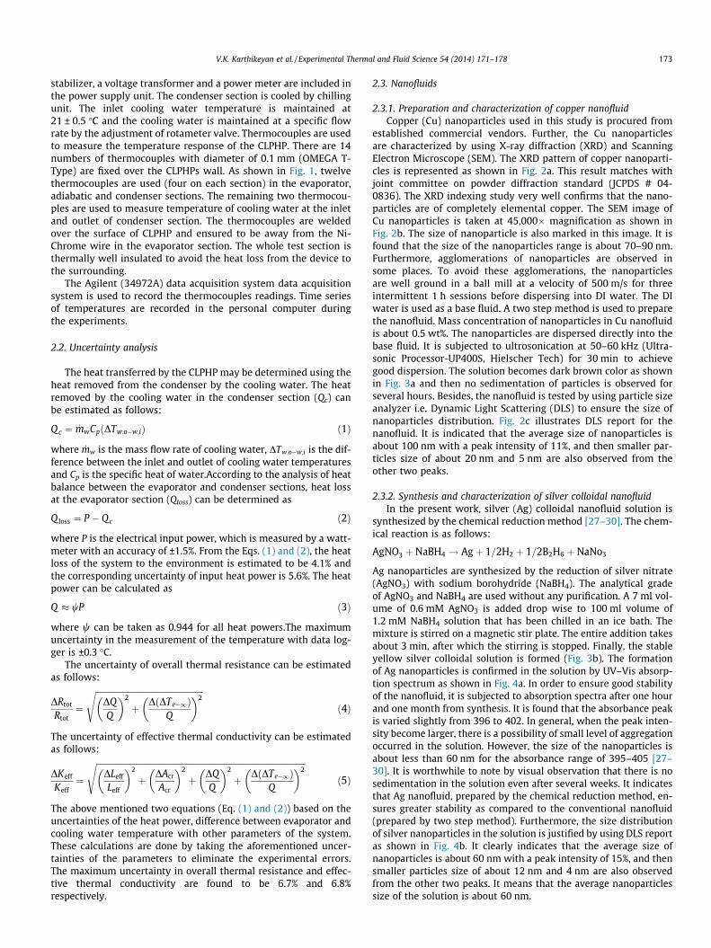
2.3.1. Preparation and characterization of copper nanofluidCopper (Cu) nanoparticles used in this study is procured from
established commercial vendors. Further, the Cu nanoparticlesare characterized by using X-ray diffraction (XRD) and ScanningElectron Microscope (SEM). The XRD pattern of copper nanoparti-cles is represented as shown in Fig. 2a. This result matches withjoint committee on powder diffraction standard (JCPDS # 04-0836). The XRD indexing study very well confirms that the nano-particles are of completely elemental copper. The SEM image ofCu nanoparticles is taken at 45,000� magnification as shown inFig. 2b. The size of nanoparticle is also marked in this image. It isfound that the size of the nanoparticles range is about 70–90 nm.Furthermore, agglomerations of nanoparticles are observed insome places. To avoid these agglomerations, the nanoparticlesare well ground in a ball mill at a velocity of 500 m/s for threeintermittent 1 h sessions before dispersing into DI water. The DIwater is used as a base fluid. A two step method is used to preparethe nanofluid. Mass concentration of nanoparticles in Cu nanofluidis about 0.5 wt%. The nanoparticles are dispersed directly into thebase fluid. It is subjected to ultrosonication at 50–60 kHz (Ultra-sonic Processor-UP400S, Hielscher Tech) for 30 min to achievegood dispersion. The solution becomes dark brown color as shownin Fig. 3a and then no sedimentation of particles is observed forseveral hours. Besides, the nanofluid is tested by using particle sizeanalyzer i.e. Dynamic Light Scattering (DLS) to ensure the size ofnanoparticles distribution. Fig. 2c illustrates DLS report for thenanofluid. It is indicated that the average size of nanoparticles isabout 100 nm with a peak intensity of 11%, and then smaller par-ticles size of about 20 nm and 5 nm are also observed from theother two peaks.
2.3.2. Synthesis and characterization of silver colloidal nanofluidIn the present work, silver (Ag) colloidal nanofluid solution is
synthesized by the chemical reduction method [27–30]. The chem-ical reaction is as follows:
AgNO3 þ NaBH4 ! Agþ 1=2H2 þ 1=2B2H6 þ NaNo3
Ag nanoparticles are synthesized by the reduction of silver nitrate(AgNO3) with sodium borohydride (NaBH4). The analytical gradeof AgNO3 and NaBH4 are used without any purification. A 7 ml vol-ume of 0.6 mM AgNO3 is added drop wise to 100 ml volume of1.2 mM NaBH4 solution that has been chilled in an ice bath. Themixture is stirred on a magnetic stir plate. The entire addition takesabout 3 min, after which the stirring is stopped. Finally, the stableyellow silver colloidal solution is formed (Fig. 3b). The formationof Ag nanoparticles is confirmed in the solution by UV–Vis absorp-tion spectrum as shown in Fig. 4a. In order to ensure good stabilityof the nanofluid, it is subjected to absorption spectra after one hourand one month from synthesis. It is found that the absorbance peakis varied slightly from 396 to 402. In general, when the peak inten-sity become larger, there is a possibility of small level of aggregationoccurred in the solution. However, the size of the nanoparticles isabout less than 60 nm for the absorbance range of 395–405 [27–30]. It is worthwhile to note by visual observation that there is nosedimentation in the solution even after several weeks. It indicatesthat Ag nanofluid, prepared by the chemical reduction method, en-sures greater stability as compared to the conventional nanofluid(prepared by two step method). Furthermore, the size distributionof silver nanoparticles in the solution is justified by using DLS reportas shown in Fig. 4b. It clearly indicates that the average size ofnanoparticles is about 60 nm with a peak intensity of 15%, and thensmaller particles size of about 12 nm and 4 nm are also observedfrom the other two peaks. It means that the average nanoparticlessize of the solution is about 60 nm.
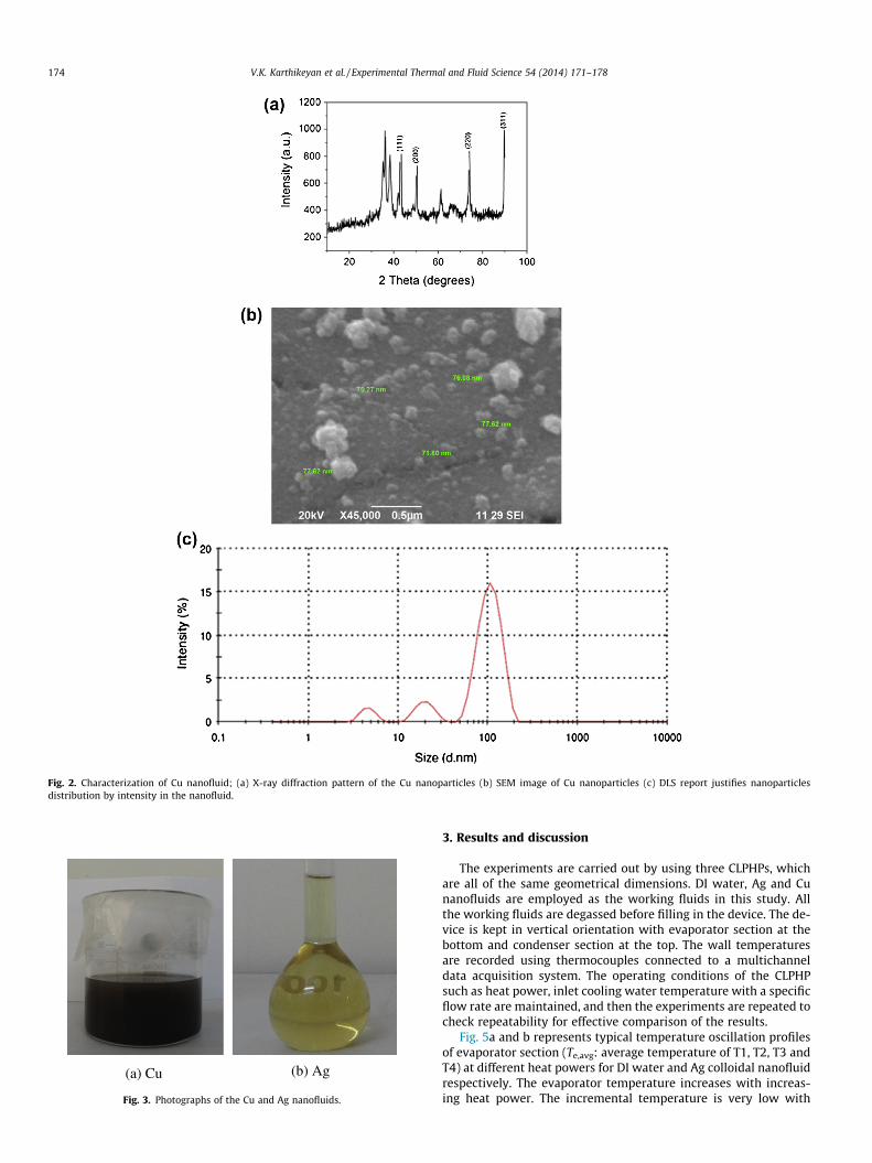
Fig. 2. Characterization of Cu nanofluid; (a) X-ray diffraction pattern of the Cu nanoparticles (b) SEM image of Cu nanoparticles (c) DLS report justifies nanoparticlesdistribution by intensity in the nanofluid.
(b) Ag (a) Cu
Fig. 3. Photographs of the Cu and Ag nanofluids.
174 V.K. Karthikeyan et al. / Experimental Thermal and Fluid Science 54 (2014) 171–178
3. Results and discussion
The experiments are carried out by using three CLPHPs, whichare all of the same geometrical dimensions. DI water, Ag and Cunanofluids are employed as the working fluids in this study. Allthe working fluids are degassed before filling in the device. The de-vice is kept in vertical orientation with evaporator section at thebottom and condenser section at the top. The wall temperaturesare recorded using thermocouples connected to a multichanneldata acquisition system. The operating conditions of the CLPHPsuch as heat power, inlet cooling water temperature with a specificflow rate are maintained, and then the experiments are repeated tocheck repeatability for effective comparison of the results.
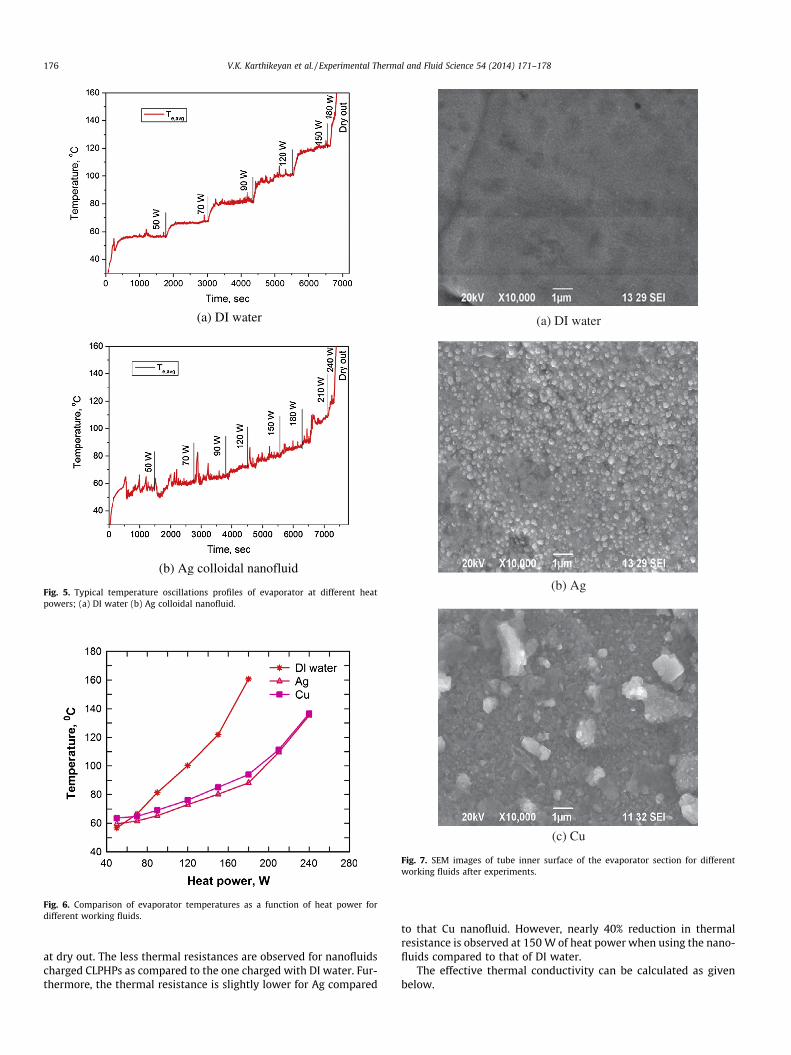
Fig. 5a and b represents typical temperature oscillation profilesof evaporator section (Te,avg: average temperature of T1, T2, T3 andT4) at different heat powers for DI water and Ag colloidal nanofluidrespectively. The evaporator temperature increases with increas-ing heat power. The incremental temperature is very low with
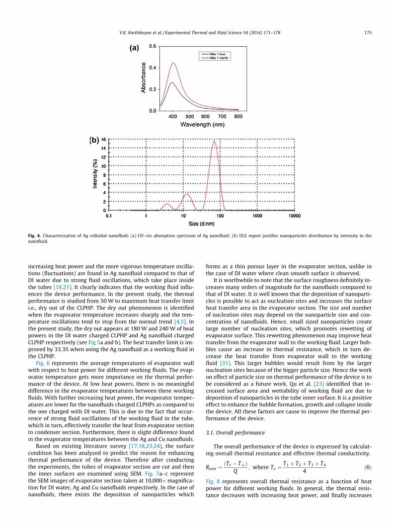
Fig. 4. Characterization of Ag colloidal nanofluid; (a) UV–vis absorption spectrum of Ag nanofluid; (b) DLS report justifies nanoparticles distribution by intensity in thenanofluid.
V.K. Karthikeyan et al. / Experimental Thermal and Fluid Science 54 (2014) 171–178 175
increasing heat power and the more vigorous temperature oscilla-tions (fluctuations) are found in Ag nanofluid compared to that ofDI water due to strong fluid oscillations, which take place insidethe tubes [18,21]. It clearly indicates that the working fluid influ-ences the device performance. In the present study, the thermalperformance is studied from 50 W to maximum heat transfer limiti.e., dry out of the CLPHP. The dry out phenomenon is identifiedwhen the evaporator temperature increases sharply and the tem-perature oscillations tend to stop from the normal trend [4,5]. Inthe present study, the dry out appears at 180 W and 240 W of heatpowers in the DI water charged CLPHP and Ag nanofluid chargedCLPHP respectively (see Fig 5a and b). The heat transfer limit is im-proved by 33.3% when using the Ag nanofluid as a working fluid inthe CLPHP.
Fig. 6 represents the average temperatures of evaporator wallwith respect to heat power for different working fluids. The evap-orator temperature gets more importance on the thermal perfor-mance of the device. At low heat powers, there is no meaningfuldifference in the evaporator temperatures between these workingfluids. With further increasing heat power, the evaporator temper-atures are lower for the nanofluids charged CLPHPs as compared tothe one charged with DI water. This is due to the fact that occur-rence of strong fluid oscillations of the working fluid in the tube,which in turn, effectively transfer the heat from evaporator sectionto condenser section. Furthermore, there is slight difference foundin the evaporator temperatures between the Ag and Cu nanofluids.
Based on existing literature survey [17,18,23,24], the surfacecondition has been analyzed to predict the reason for enhancingthermal performance of the device. Therefore after conductingthe experiments, the tubes of evaporator section are cut and thenthe inner surfaces are examined using SEM. Fig. 7a–c representthe SEM images of evaporator section taken at 10,000�magnifica-tion for DI water, Ag and Cu nanofluids respectively. In the case ofnanofluids, there exists the deposition of nanoparticles which
forms as a thin porous layer in the evaporator section, unlike inthe case of DI water where clean smooth surface is observed.
It is worthwhile to note that the surface roughness definitely in-creases many orders of magnitude for the nanofluids compared tothat of DI water. It is well known that the deposition of nanoparti-cles is possible to act as nucleation sites and increases the surfaceheat transfer area in the evaporator section. The size and numberof nucleation sites may depend on the nanoparticle size and con-centration of nanofluids. Hence, small sized nanoparticles createlarge number of nucleation sites, which promotes rewetting ofevaporator surface. This rewetting phenomenon may improve heattransfer from the evaporator wall to the working fluid. Larger bub-bles cause an increase in thermal resistance, which in turn de-crease the heat transfer from evaporator wall to the workingfluid [31]. This larger bubbles would result from by the largernucleation sites because of the bigger particle size. Hence the workon effect of particle size on thermal performance of the device is tobe considered as a future work. Qu et al. [23] identified that in-creased surface area and wettability of working fluid are due todeposition of nanoparticles in the tube inner surface. It is a positiveeffect to enhance the bubble formation, growth and collapse insidethe device. All these factors are cause to improve the thermal per-formance of the device.
3.1. Overall performance
The overall performance of the device is expressed by calculat-ing overall thermal resistance and effective thermal conductivity.
Rover ¼ðTe � T1Þ
Q; where Te ¼
T1 þ T2 þ T3 þ T4
4ð6Þ
Fig. 8 represents overall thermal resistance as a function of heatpower for different working fluids. In general, the thermal resis-tance decreases with increasing heat power, and finally increases
(a) DI water
(b) Ag colloidal nanofluid
Fig. 5. Typical temperature oscillations profiles of evaporator at different heatpowers; (a) DI water (b) Ag colloidal nanofluid.
Fig. 6. Comparison of evaporator temperatures as a function of heat power fordifferent working fluids.
(c) Cu
(a) DI water
(b) Ag
Fig. 7. SEM images of tube inner surface of the evaporator section for differentworking fluids after experiments.
176 V.K. Karthikeyan et al. / Experimental Thermal and Fluid Science 54 (2014) 171–178
at dry out. The less thermal resistances are observed for nanofluidscharged CLPHPs as compared to the one charged with DI water. Fur-thermore, the thermal resistance is slightly lower for Ag compared
to that Cu nanofluid. However, nearly 40% reduction in thermalresistance is observed at 150 W of heat power when using the nano-fluids compared to that of DI water.
The effective thermal conductivity can be calculated as givenbelow.
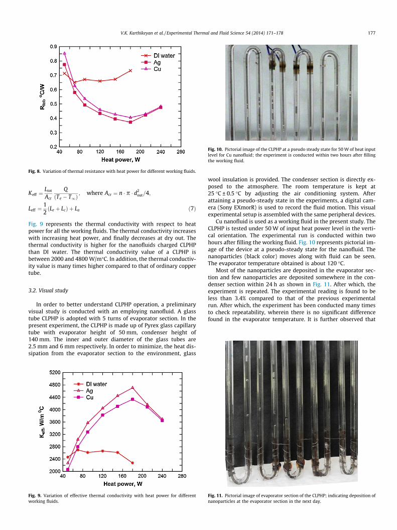
Fig. 8. Variation of thermal resistance with heat power for different working fluids.
Fig. 10. Pictorial image of the CLPHP at a pseudo steady state for 50 W of heat inputlevel for Cu nanofluid; the experiment is conducted within two hours after fillingthe working fluid.
V.K. Karthikeyan et al. / Experimental Thermal and Fluid Science 54 (2014) 171–178 177
Keff ¼Ltot
Acr
QðTe � T1Þ
; where Acr ¼ n � p � d2out=4;
Leff ¼12ðLe þ LcÞ þ La ð7Þ
Fig. 9 represents the thermal conductivity with respect to heatpower for all the working fluids. The thermal conductivity increaseswith increasing heat power, and finally decreases at dry out. Thethermal conductivity is higher for the nanofluids charged CLPHPthan DI water. The thermal conductivity value of a CLPHP isbetween 2000 and 4800 W/m�C. In addition, the thermal conductiv-ity value is many times higher compared to that of ordinary coppertube.
3.2. Visual study
In order to better understand CLPHP operation, a preliminaryvisual study is conducted with an employing nanofluid. A glasstube CLPHP is adopted with 5 turns of evaporator section. In thepresent experiment, the CLPHP is made up of Pyrex glass capillarytube with evaporator height of 50 mm, condenser height of140 mm. The inner and outer diameter of the glass tubes are2.5 mm and 6 mm respectively. In order to minimize, the heat dis-sipation from the evaporator section to the environment, glass
Fig. 9. Variation of effective thermal conductivity with heat power for differentworking fluids.
wool insulation is provided. The condenser section is directly ex-posed to the atmosphere. The room temperature is kept at25 �C ± 0.5 �C by adjusting the air conditioning system. Afterattaining a pseudo-steady state in the experiments, a digital cam-era (Sony EXmorR) is used to record the fluid motion. This visualexperimental setup is assembled with the same peripheral devices.
Cu nanofluid is used as a working fluid in the present study. TheCLPHP is tested under 50 W of input heat power level in the verti-cal orientation. The experimental run is conducted within twohours after filling the working fluid. Fig. 10 represents pictorial im-age of the device at a pseudo-steady state for the nanofluid. Thenanoparticles (black color) moves along with fluid can be seen.The evaporator temperature obtained is about 120 �C.
Most of the nanoparticles are deposited in the evaporator sec-tion and few nanoparticles are deposited somewhere in the con-denser section within 24 h as shown in Fig. 11. After which, theexperiment is repeated. The experimental reading is found to beless than 3.4% compared to that of the previous experimentalrun. After which, the experiment has been conducted many timesto check repeatability, wherein there is no significant differencefound in the evaporator temperature. It is further observed that
Fig. 11. Pictorial image of evaporator section of the CLPHP; indicating deposition ofnanoparticles at the evaporator section in the next day.
178 V.K. Karthikeyan et al. / Experimental Thermal and Fluid Science 54 (2014) 171–178
most of the particles are stuck in the evaporator section and thenfew nanoparticles only move along with the fluid under the oper-ating conditions. It is a clear evident that the sticking i.e., deposi-tion of the nanoparticles, which act as nucleation sites in theevaporator section and is the main cause for improving thermalperformance of the device.
4. Conclusions
An experimental investigation has been carried out to predictthe thermal performance of the CLPHPs, which is charged withDI water, Ag colloidal and Cu nanofluids. The detailed preparationand characterization of nanofluids are done in this study. Besides, avisual study is carried out to understand the device operation. Thefollowing conclusions are drawn from this study.
� The presence of nanoparticles in the working fluid is the maincause for creating nucleation sites which in turn increase sur-face heart transfer area in the evaporator section thereforeenhancing the performance of the device.� The strong temperature oscillations are accomplished while
using nanofluid as a working fluid under CLPHP operation.� Nanofluids are considered as alternative potential heat transfer
working fluids due to the fact they offer lower evaporator tem-perature, lower thermal resistance, higher effective thermalconductivity and 33.3% of higher heat transfer limit for nano-fluid as compared to that DI water.
Acknowledgements
The authors would like to thank Professor Sameer Khandekar(Department of Mechanical Engineering, Indian Institute of Tech-nology Kanpur) for his invaluable help and guidance. Award of Ju-nior Research Fellowship by UGC is gratefully acknowledged by thefirst author.
References
[1] H. Akachi, Structure of a heat pipe, US Patent # 4991041, 1990.[2] H. Akachi, Structure of micro-heat pipe, US Patent # 5219020, 1993.[3] H. Akachi, F. Polas�ek, P.S�tulc, Pulsating heat pipes, in: Proceedings of the Fifth
International Heat Pipe Symposium, Melbourne, Australia, (1996) 208–217.[4] S. Khandekar, N. Dollinger, M. Groll, Understanding operational regimes of
pulsating heat pipes: an experimental study, Appl. Therm. Eng. 23 (2003) 707–719.
[5] P. Charoensawan, S. Khandekar, M. Groll, P. Terdtoon, Closed loop pulsatingheat pipes -Part A: parametric experimental investigations, Appl. Therm. Eng.23 (2003) 2009–2020.
[6] S. Khandekar, P. Charoensawan, M. Groll, P. Terdtoon, Closed loop pulsatingheat pipes -Part B: visualization and semi-empirical modeling, Appl. Therm.Eng. 23 (2003) 2021–2033.
[7] X.M. Zhang, J.L. Xu, Z.Q. Zhou, Experimental study of a pulsating heat pipeusing FC-72, ethanol and water as working fluids, Exp. Heat Transfer 17 (2004)47–67.
[8] J.L. Xu, X.M. Zhang, Start-up and steady thermal oscillation of a pulsating heatpipe, Heat Mass Transfer 41 (2005) 685–694.
[9] S. Rittidech, P. Terdtoon, M. Murakami, P. Kamonpet, W. Jompakdee,Correlation to predict heat transfer characteristics of a closed end oscillatingheat pipe at normal operating condition, Appl. Therm. Eng. 23 (2003) 497–510.
[10] B.Y. Tong, T.N. Wong, K. Ooi, Closed-loop pulsating heat pipe, Appl. Therm. Eng.21 (18) (2001) 1845–1862.
[11] J.L. Xu, Y.X. Li, T.N. Wong, High speed flow visualization of a closed looppulsating heat pipe, Int. J. Heat Mass Transfer 48 (2005) 3338–3351.
[12] J.S. Kim, N.H. Bui, J.W. Kim, J.H. Kim, H.S. Jung, Flow visualization of oscillationcharacteristics of liquid and vapor flow in the oscillating capillary tube heatpipe, J. Mech. Sci. Technol. 17 (10) (2003) 1507–1519.
[13] S.U.S. Choi, J.A. Eastman, Enhancing thermal conductivity of fluids withnanoparticles, in: D.A. Siginer, H.P. Wang (Eds.), Developments andApplications of Non-Newtonian Flows, ASME, 1995, pp. 99–105.
[14] S. Lee, S.U.S. Choi, J.A. Eastman, S. Lee, Measuring thermal conductivity of fluidcontaining oxide nanoparticle, J. Heat Transfer 121 (1999) 280–2893.
[15] J.A. Eastman, S.U.S. Choi, S. Li, W. Yu, L.J. Thomson, Anomalously increasedeffective thermal conductivities of ethylene glycol-based nanofluidscontaining copper nanoparticles, Appl. Phys. Lett. 78 (2001) 718–7204.
[16] S.K. Das, N. Putra, P. Thiesen, W. Roetzel, Temperature dependence of thermalconductivity enhancement for nano fluids, J. Heat Transfer 125 (2003). 567–57.
[17] C.Y. Tsai, H.T. Chien, P.P. Ding, B. Chan, T.Y. Luh, P.H. Chen, Effect of structuralcharacter of gold nanoparticles in nanofluid on heat pipe thermalperformance, Mater. Lett. 58 (2004) 1461–1465.
[18] H.B. Ma, C. Wilson, Q. Yu, K. Park, S.U.S. Choi, Murli Tirumala, An experimentalinvestigation of heat transport capability in a nanofluid oscillating heat pipe, J.Heat Transfer 128 (2006) 1213–1216.
[19] Y.-H. Lin, S.W. Kang, H.L. Chen, Effect of silver nano-fluid on pulsating heatpipe thermal performance, Appl. Therm. Eng. 28 (2008) 1312–1317.
[20] N. Bhuwakietkumjohn, S. Rittidech, Internal flow patterns on heat transfercharacteristics of a closed-loop oscillating heat-pipe with check valves usingethanol and a silver nano-ethanol mixture, Exp. Therm. Fluid Sci. 34 (8) (2010)1000–1007.
[21] Q-M. Li, Jiang Zou, Zhen Yang, Yuan-Yuan Duan, Bu-Xuan Wang, Visualizationof two-phase flows in nanofluid oscillating heat pipes, J. Heat Transfer 133(2011). 052901-1.
[22] Y. Ji, H.B. Ma, Fengmin Su, Guoyou Wanga, Particle size effect on heat transferperformance in an oscillating heat pipe, Exp. Therm. Fluid Sci. 35 (2011) 724–727.
[23] J. Qu, Huiying Wu, Thermal performance comparison of oscillating heat pipeswith SiO2/water and Al2O3/water nanofluids, Int. J. Therm. Sci. 50 (2011)1954–1962.
[24] S. Khandekar, Yogesh M. Joshi, Balkrishna Mehta, Thermal performance ofclosed two-phase thermosyphon using nanofluids, Int. J. Therm. Sci. 47 (2008)659–667.
[25] Lixin. Cheng, Lei. Liu, Boiling and two phase flow phenomena of refrigerant-based nanofluids: fundamentals, applications and challenges, Int. J.Refrigeration 36 (2013) 421–446.
[26] Lixin Cheng, Nanofluid heat transfer technologies, Recent Pat. Eng. 3 (1) (2009)1–7.
[27] Lixin Cheng, Enio P. Bandarra Filho, John R. Thome, Nanofluid two-phase flowand thermal physics: a new research frontier of nanotechnology and itschallenges, J. Nanosci. Nanotech. 8 (2008) 3315–3332.
[28] Sally.D. Solomon, Mozghan. Bahadory, Aravindan.V. Jeyarajasingam, Susan.A.Rutkowsky, Charles. Boritz, Lorraine. Mulfinger, Synthesis and study of silvernanoparticles, J. Chem. Educ. 84 (2) (2007) 322–325.
[29] Y. Fang, Optical absorption of nanoscale colloidal silver: aggregate band andadsorbate silver surface band, J. Chem. Phys. 108 (1998) 4315–4319.
[30] P. Manikandan, V. Ramakrishnan, Spectral investigations on N-(2-Methylthiophenyl)-2-Hydroxy-1-Naphthaldimine by silver Nanoparticles:quenching, J. Fluoresc. 21 (2011) 693–699.
[31] B.B. Mikic, W.M. Rohsenow, A new correlation of pool-boiling data includingthe effect of heating surface characteristics, J. Heat Transfer 91 (1969) 245–250.