investigation of sio2 etch characteristics by c6f6/ar/o2
TRANSCRIPT
�����������������
Citation: Sung, D.; Wen, L.; Tak, H.;
Lee, H.; Kim, D.; Yeom, G.
Investigation of SiO2 Etch
Characteristics by C6F6/Ar/O2
Plasmas Generated Using Inductively
Coupled Plasma and Capacitively
Coupled Plasma. Materials 2022, 15,
1300. https://doi.org/10.3390/
ma15041300
Academic Editor:
Edward Bormashenko
Received: 7 January 2022
Accepted: 4 February 2022
Published: 10 February 2022
Publisher’s Note: MDPI stays neutral
with regard to jurisdictional claims in
published maps and institutional affil-
iations.
Copyright: © 2022 by the authors.
Licensee MDPI, Basel, Switzerland.
This article is an open access article
distributed under the terms and
conditions of the Creative Commons
Attribution (CC BY) license (https://
creativecommons.org/licenses/by/
4.0/).
materials
Article
Investigation of SiO2 Etch Characteristics by C6F6/Ar/O2Plasmas Generated Using Inductively Coupled Plasma andCapacitively Coupled PlasmaDain Sung 1,† , Long Wen 1,†, Hyunwoo Tak 1, Hyejoo Lee 1, Dongwoo Kim 1 and Geunyoung Yeom 1,2,*
1 Department of Advanced Materials Science and Engineering, Sungkyunkwan University,Suwon 16419, Korea; [email protected] (D.S.); [email protected] (L.W.);[email protected] (H.T.); [email protected] (H.L.); [email protected] (D.K.)
2 SKKU Advanced Institute of Nano Technology (SAINT), Sungkyunkwan University, Suwon 16419, Korea* Correspondence: [email protected]; Tel.: +82-31-299-6564† These authors contributed equally to this work.
Abstract: The etching properties of C6F6/Ar/O2 in both an inductively coupled plasma (ICP) systemand a capacitively coupled plasma (CCP) system were evaluated to investigate the effects of high C/Fratio of perfluorocarbon (PFC) gas on the etch characteristics of SiO2. When the SiO2 masked withACL was etched with C6F6, for the CCP system, even though the etch selectivity was very high (20 ~infinite), due to the heavy-ion bombardment possibly caused by the less dissociated high-mass ionsfrom C6F6, tapered SiO2 etch profiles were observed. In the case of the ICP system, due to the higherdissociation of C6F6 and O2 compared to the CCP system, the etching of SiO2 required a much lowerratio of O2/C6F6 (~1.0) while showing a higher maximum SiO2 etch rate (~400 nm/min) and a loweretch selectivity (~6.5) compared with the CCP system. For the ICP etching, even though the etchselectivity was much lower than that by the CCP etching, due to less heavy-mass-ion bombardment inaddition to an adequate fluorocarbon layer formation on the substrate caused by heavily dissociatedspecies, highly anisotropic SiO2 etch profiles could be obtained at the optimized condition of theO2/C6F6 ratio (~1.0).
Keywords: inductively coupled plasma (ICP); capacitively coupled plasma (CCP); liquid fluorocarbon(PFC); L-FC; C6F6; plasma etching; high aspect ratio contact (HARC)
1. Introduction
As the semiconductor device size has decreased to nanoscale due to the high integra-tion of the circuit, the critical dimension has decreased to a few nanometers and the devicestructure has changed from 2D to 3D. To fabricate these devices, etching technologiessuch as pulsed plasma etching technology and multiple patterning technology are widelyinvestigated [1–9] and applied using two different plasma etching systems, namely thecapacitively coupled plasma (CCP) etching system and inductively coupled plasma (ICP)etching system.
The CCP system uses two facing electrodes, and multiple RF powers composed ofhigh and low RF frequencies are generally applied to both the top and bottom electrodes orto the bottom electrode only; to provide ion energy to the substrate located at the bottomelectrode, a lower frequency RF power is generally connected to the bottom electrode. Dueto the electric field configuration of the CCP system, the CCP system tends to show a lowplasma density of ~109–10/cm3 and a low gas dissociation. In the case of the ICP system,one RF power is connected to the inductive antenna located at the top of the chamberfor the generation of time-varying azimuthal electric fields in the process chamber forthe high-density plasma formation of ~1010–11/cm3 with a significant gas dissociation,and a low-frequency RF power is also connected to the bottom electrode to provide ion
Materials 2022, 15, 1300. https://doi.org/10.3390/ma15041300 https://www.mdpi.com/journal/materials
Materials 2022, 15, 1300 2 of 11
bombardment to the substrate [10]. The ICP system is generally operated at a low pressureof a few millitorr, and etch rates are generally higher than those by the CCP system operatedat a few tens of millitorr due to the higher ion flux and higher radical flux of the ICP systemduring the etching. However, for the high aspect ratio contact (HARC) etching of SiO2using perfluorocarbon (PFC)-based etch gases, even though the etch rates are slower thanthe ICP system, the CCP system is generally used due to the higher etch selectivity overmask layers caused by low dissociation of fluorocarbon gases at the lower plasma densityin addition to the higher ion bombardment energy at the same low-frequency power tothe substrate.
Previously, to obtain higher etch selectivity over mask layers in addition to high HARCSiO2 etch rates, researchers have investigated using the ICP system instead of the CCPsystem for the HARC etching [11–14]. Li et al. used C4F6 gas for the etching of SiO2 maskedwith photoresist in an ICP system, and even though the etch selectivity of SiO2/PR washigher than conventional PFC gas of C4F8, the maximum etch selectivity was limited to4 [11]. Nakamura et al. also etched SiO2 masked with photoresist in an ICP system withvarious PFC gases having different C/F ratios such as C3F6, C4F6, C4F8, and C5F8 andshowed that the higher C/F ratio improved the etch selectivity but the maximum etchselectivity obtained with C4F6 was 2 [12]. Kim et al. used hydrofluoroether-based gasesin the etching of SiO2 with an ICP system, but no etch selectivity data were provided [13].Therefore, even though studies have been carried out to etch SiO2 selectively to masklayers using the ICP system, no sufficient investigation has been carried out and no resultsapplicable to HARC SiO2 etching have been reported.
During the etching of SiO2 using the PFC gases, PFC gases are dissociated/ionized, andthe characteristics of the dissociation/ionization affect the etch characteristics of SiO2 suchas etch rates, etch selectivity over mask layers, and etch profile. Because the characteristicsof the dissociation/ionization of the PFCs by ICP and CCP systems are different, the HARCSiO2 etch characteristics will be different; however, currently, no detailed research resultscan be found in the literature on the differences between the ICP system and the CCPsystem for the dissociation/ionization of PFCs and their relationship to the etching ofHARC SiO2 using the same PFC gases. Moreover, the reason for the use of the CCP systemfor the HARC etching instead of the ICP system is due to the lower dissociation of thefluorocarbon gas to have high C/F ratio radicals/ions in the plasma for the higher etchselectivity over mask layers, but no research has been carried out using a perfluorocarbongas with the high C/F ratio ≥ 1.0 such as C6F6 for higher C/F ratio radicals/ions even forthe higher gas dissociation. In this study, using a PFC gas having a high C/F ratio of C6F6,the differences in the plasma characteristics of the C6F6 and the etch characteristics such asetch rate, etch selectivity over a hard mask layer, and etch profile were compared betweenthe ICP system and the CCP system. In addition, the possibility of using the ICP systemin HARC SiO2 etching masked with an amorphous carbon layer (ACL) was investigated.In the case of C6F6, in addition to a high C/F ratio, the global warming potential (GWP)is very low compared to some of PFC gases generally used for HARC SiO2 etching suchas CF4 and C4F8 [15–17], as shown in Table 1, and its boiling point is lower than 0 ◦C (aliquid PFC); therefore, if required, the undissociated C6F6 can be collected at the exhaustline, which can reduce the global warming effect further.
Table 1. The lifetimes and 100-year GWPs of perfluorocarbon gases CF4, c-C4F8, C2F6, and C6F6
based on the IPCC reports [18].
Gas Species Chemical Formula Lifetime (Years) GWP100 years
Perfluoromethane CF4 50,000 6500Perfluorocyclobutane c-C4F8 3200 8700
Perfluoroethane C2F6 10,000 9200Hexafluorobenzene C6F6 0.23 7
Materials 2022, 15, 1300 3 of 11
2. Materials and Methods
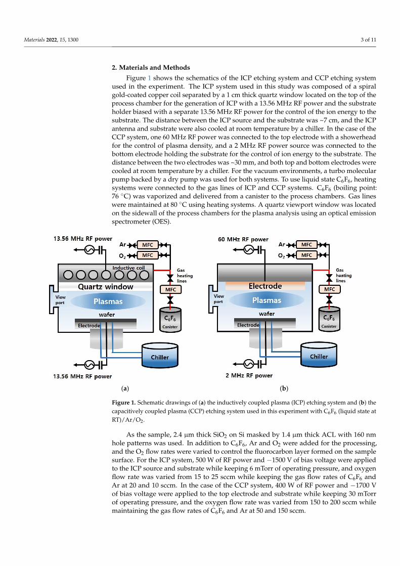
Figure 1 shows the schematics of the ICP etching system and CCP etching systemused in the experiment. The ICP system used in this study was composed of a spiralgold-coated copper coil separated by a 1 cm thick quartz window located on the top of theprocess chamber for the generation of ICP with a 13.56 MHz RF power and the substrateholder biased with a separate 13.56 MHz RF power for the control of the ion energy to thesubstrate. The distance between the ICP source and the substrate was ~7 cm, and the ICPantenna and substrate were also cooled at room temperature by a chiller. In the case of theCCP system, one 60 MHz RF power was connected to the top electrode with a showerheadfor the control of plasma density, and a 2 MHz RF power source was connected to thebottom electrode holding the substrate for the control of ion energy to the substrate. Thedistance between the two electrodes was ~30 mm, and both top and bottom electrodes werecooled at room temperature by a chiller. For the vacuum environments, a turbo molecularpump backed by a dry pump was used for both systems. To use liquid state C6F6, heatingsystems were connected to the gas lines of ICP and CCP systems. C6F6 (boiling point:76 ◦C) was vaporized and delivered from a canister to the process chambers. Gas lineswere maintained at 80 ◦C using heating systems. A quartz viewport window was locatedon the sidewall of the process chambers for the plasma analysis using an optical emissionspectrometer (OES).
Materials 2021, 14, x FOR PEER REVIEW 3 of 13
Table 1. The lifetimes and 100-year GWPs of perfluorocarbon gases CF4, c-C4F8, C2F6, and C6F6 based
on the IPCC reports [18].
Gas Species Chemical Formula Lifetime (Years) GWP100 years
Perfluoromethane CF4 50,000 6500
Perfluorocyclobutane c-C4F8 3200 8700
Perfluoroethane C2F6 10,000 9200
Hexafluorobenzene C6F6 0.23 7
2. Materials and Methods
Figure 1 shows the schematics of the ICP etching system and CCP etching system
used in the experiment. The ICP system used in this study was composed of a spiral gold-
coated copper coil separated by a 1 cm thick quartz window located on the top of the
process chamber for the generation of ICP with a 13.56 MHz RF power and the substrate
holder biased with a separate 13.56 MHz RF power for the control of the ion energy to the
substrate. The distance between the ICP source and the substrate was ~7 cm, and the ICP
antenna and substrate were also cooled at room temperature by a chiller. In the case of the
CCP system, one 60 MHz RF power was connected to the top electrode with a showerhead
for the control of plasma density, and a 2 MHz RF power source was connected to the
bottom electrode holding the substrate for the control of ion energy to the substrate. The
distance between the two electrodes was ~30 mm, and both top and bottom electrodes
were cooled at room temperature by a chiller. For the vacuum environments, a turbo mo-
lecular pump backed by a dry pump was used for both systems. To use liquid state C6F6,
heating systems were connected to the gas lines of ICP and CCP systems. C6F6 (boiling
point: 76 °C) was vaporized and delivered from a canister to the process chambers. Gas
lines were maintained at 80 °C using heating systems. A quartz viewport window was
located on the sidewall of the process chambers for the plasma analysis using an optical
emission spectrometer (OES).
(a) (b)
Figure 1. Schematic drawings of (a) the inductively coupled plasma (ICP) etching system and (b)
the capacitively coupled plasma (CCP) etching system used in this experiment with C6F6 (liquid
state at RT)/Ar/O2.
As the sample, 2.4 μm thick SiO2 on Si masked by 1.4 μm thick ACL with 160 nm hole
patterns was used. In addition to C6F6, Ar and O2 were added for the processing, and the
O2 flow rates were varied to control the fluorocarbon layer formed on the sample surface.
Figure 1. Schematic drawings of (a) the inductively coupled plasma (ICP) etching system and (b) thecapacitively coupled plasma (CCP) etching system used in this experiment with C6F6 (liquid state atRT)/Ar/O2.
As the sample, 2.4 µm thick SiO2 on Si masked by 1.4 µm thick ACL with 160 nmhole patterns was used. In addition to C6F6, Ar and O2 were added for the processing,and the O2 flow rates were varied to control the fluorocarbon layer formed on the samplesurface. For the ICP system, 500 W of RF power and −1500 V of bias voltage were appliedto the ICP source and substrate while keeping 6 mTorr of operating pressure, and oxygenflow rate was varied from 15 to 25 sccm while keeping the gas flow rates of C6F6 andAr at 20 and 10 sccm. In the case of the CCP system, 400 W of RF power and −1700 Vof bias voltage were applied to the top electrode and substrate while keeping 30 mTorrof operating pressure, and the oxygen flow rate was varied from 150 to 200 sccm whilemaintaining the gas flow rates of C6F6 and Ar at 50 and 150 sccm.
Materials 2022, 15, 1300 4 of 11
The etch depths of SiO2/ACL and the SiO2 etch profiles were observed using fieldemission scanning electron microscopy (FE-SEM, Hitachi S-4700) after the etching usingICP and CCP, and the etch rates and etch selectivity were calculated. The compositionsand binding states of the etched SiO2 surfaces were observed using X-ray photoelectronspectroscopy (XPS, Fisons Instruments Surface Systems ESCALAB 220i). Then, to fit thespectrum of the C1s peak and to calculate the atomic percentages on the SiO2 surfaces, anXPS peak-fitting software (software name: Thermo Scientific Avantage) and the Originprogram (Origin Lab Corporation) were used. The differences in the dissociation speciesof C6F6 in the ICP and CCP used in our experimental conditions were observed using anoptical emission spectroscope (OES, Isoplane SCT3200, Andor iStar 734).
3. Results and Discussion
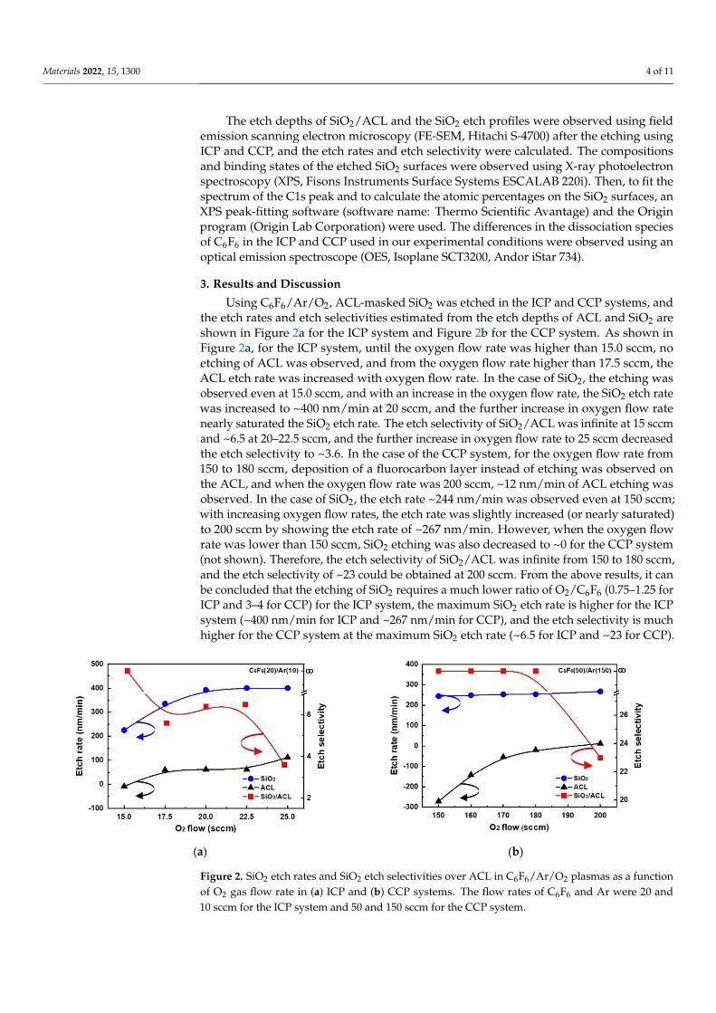
Using C6F6/Ar/O2, ACL-masked SiO2 was etched in the ICP and CCP systems, andthe etch rates and etch selectivities estimated from the etch depths of ACL and SiO2 areshown in Figure 2a for the ICP system and Figure 2b for the CCP system. As shown inFigure 2a, for the ICP system, until the oxygen flow rate was higher than 15.0 sccm, noetching of ACL was observed, and from the oxygen flow rate higher than 17.5 sccm, theACL etch rate was increased with oxygen flow rate. In the case of SiO2, the etching wasobserved even at 15.0 sccm, and with an increase in the oxygen flow rate, the SiO2 etch ratewas increased to ~400 nm/min at 20 sccm, and the further increase in oxygen flow ratenearly saturated the SiO2 etch rate. The etch selectivity of SiO2/ACL was infinite at 15 sccmand ~6.5 at 20–22.5 sccm, and the further increase in oxygen flow rate to 25 sccm decreasedthe etch selectivity to ~3.6. In the case of the CCP system, for the oxygen flow rate from150 to 180 sccm, deposition of a fluorocarbon layer instead of etching was observed onthe ACL, and when the oxygen flow rate was 200 sccm, ~12 nm/min of ACL etching wasobserved. In the case of SiO2, the etch rate ~244 nm/min was observed even at 150 sccm;with increasing oxygen flow rates, the etch rate was slightly increased (or nearly saturated)to 200 sccm by showing the etch rate of ~267 nm/min. However, when the oxygen flowrate was lower than 150 sccm, SiO2 etching was also decreased to ~0 for the CCP system(not shown). Therefore, the etch selectivity of SiO2/ACL was infinite from 150 to 180 sccm,and the etch selectivity of ~23 could be obtained at 200 sccm. From the above results, it canbe concluded that the etching of SiO2 requires a much lower ratio of O2/C6F6 (0.75–1.25 forICP and 3–4 for CCP) for the ICP system, the maximum SiO2 etch rate is higher for the ICPsystem (~400 nm/min for ICP and ~267 nm/min for CCP), and the etch selectivity is muchhigher for the CCP system at the maximum SiO2 etch rate (~6.5 for ICP and ~23 for CCP).
Materials 2021, 14, x FOR PEER REVIEW 5 of 13
(a) (b)
Figure 2. SiO2 etch rates and SiO2 etch selectivities over ACL in C6F6/Ar/O2 plasmas as a function of
O2 gas flow rate in (a) ICP and (b) CCP systems. The flow rates of C6F6 and Ar were 20 and 10 sccm
for the ICP system and 50 and 150 sccm for the CCP system.
To understand the differences in the etch characteristics of ACL-masked SiO2 with
C6F6/Ar/O2 gas mixtures between the ICP and CCP systems, the dissociation characteris-
tics of C6F6/Ar/O2 for different oxygen flow rates were investigated with OES for the wave-
length range of 200–900 nm, and the results are shown in Figure 3a for the ICP system
from 0 to 25 sccm of oxygen flow rate and Figure 3b for the CCP system from 0 to 250
sccm of oxygen flow rate. For easier comparison, the OES data were normalized by the Ar
peak at 750.4 nm. As shown in Figure 3a,b, optical emission peaks from O (777.3, 844.8
nm), F (685.7, 703.8 nm), Ar (696,7, 706.8, 738.6, 750.4, 772.5, 794.9, 800.7, 801.6, 811.6, and
826.5 nm), CO (282.7, 296.8 nm), C2 (473.7, 516.7, 563.6 nm), CF2 (245–321 nm), etc., could
be observed [19]. Among these peaks, the emission peaks related to CF2 (247 nm), CO
(297.7 nm), C2 (516.5 nm), and F (703.7 nm) normalized by Ar (750. 4 nm) measured as a
function of oxygen flow rate are shown in Figure 4a for the ICP system and b for the CCP
system. In general, during the etching of SiO2 by fluorocarbon plasmas, F radicals react
with Si on the SiO2 surface and are removed from the surface as SiFx while C radicals react
with O on the SiO2 surface and are removed from the surface as COx [20]. As shown in
Figure 4a,b, the increase in densities of radicals such as CF2, CO, C2, and F with increasing
oxygen flow rate could be observed in both the ICP system and the CCP system due to
the increased dissociation of fluorocarbon by oxygen radicals in the plasmas. However, a
more significant increase in the radicals with increasing oxygen flow rate was observed
for the ICP system even with lower oxygen flow rates. When the radical ratios of CF2/F,
CO/F, and C2/F were compared between the ICP and CCP systems, significantly high ra-
tios of CF2/F (5.0–7.1 for ICP and 0.8–1.1 for CCP), CO/F (0–8.8 for ICP and 0–1.5 for CCP),
and C2/F (15.5–41.5 for ICP and 1.4–1.8 for CCP) were observed for the ICP system due to
the significantly higher radical densities of CF2, CO, and C2 compared to F density for the
ICP system, indicating more significant dissociation of the C6F6 of the ICP system com-
pared to the CCP system.
Figure 2. SiO2 etch rates and SiO2 etch selectivities over ACL in C6F6/Ar/O2 plasmas as a functionof O2 gas flow rate in (a) ICP and (b) CCP systems. The flow rates of C6F6 and Ar were 20 and10 sccm for the ICP system and 50 and 150 sccm for the CCP system.
Materials 2022, 15, 1300 5 of 11
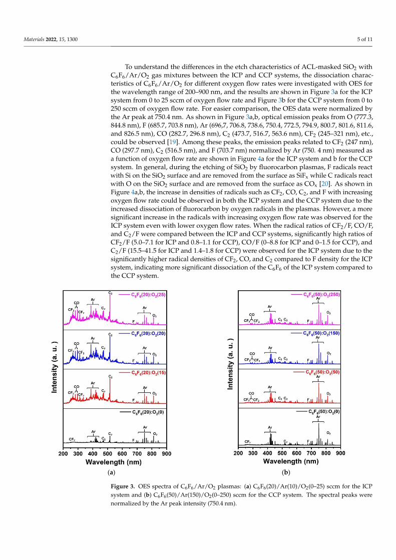
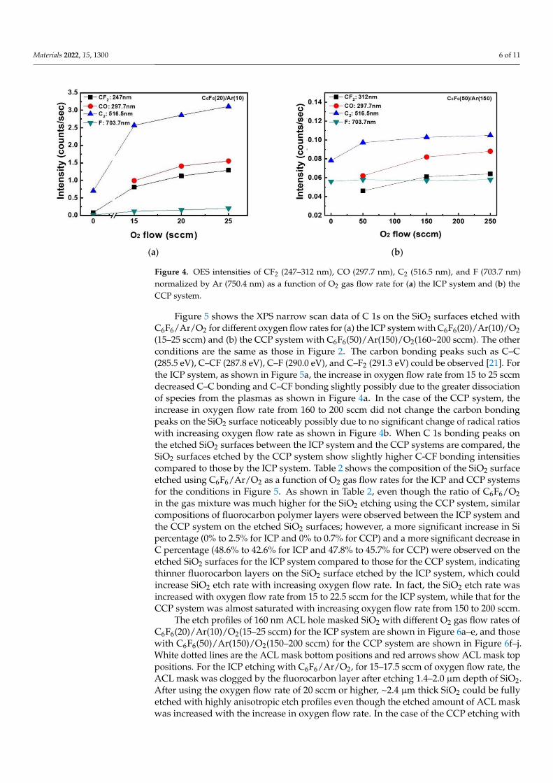
To understand the differences in the etch characteristics of ACL-masked SiO2 withC6F6/Ar/O2 gas mixtures between the ICP and CCP systems, the dissociation charac-teristics of C6F6/Ar/O2 for different oxygen flow rates were investigated with OES forthe wavelength range of 200–900 nm, and the results are shown in Figure 3a for the ICPsystem from 0 to 25 sccm of oxygen flow rate and Figure 3b for the CCP system from 0 to250 sccm of oxygen flow rate. For easier comparison, the OES data were normalized bythe Ar peak at 750.4 nm. As shown in Figure 3a,b, optical emission peaks from O (777.3,844.8 nm), F (685.7, 703.8 nm), Ar (696,7, 706.8, 738.6, 750.4, 772.5, 794.9, 800.7, 801.6, 811.6,and 826.5 nm), CO (282.7, 296.8 nm), C2 (473.7, 516.7, 563.6 nm), CF2 (245–321 nm), etc.,could be observed [19]. Among these peaks, the emission peaks related to CF2 (247 nm),CO (297.7 nm), C2 (516.5 nm), and F (703.7 nm) normalized by Ar (750. 4 nm) measured asa function of oxygen flow rate are shown in Figure 4a for the ICP system and b for the CCPsystem. In general, during the etching of SiO2 by fluorocarbon plasmas, F radicals reactwith Si on the SiO2 surface and are removed from the surface as SiFx while C radicals reactwith O on the SiO2 surface and are removed from the surface as COx [20]. As shown inFigure 4a,b, the increase in densities of radicals such as CF2, CO, C2, and F with increasingoxygen flow rate could be observed in both the ICP system and the CCP system due to theincreased dissociation of fluorocarbon by oxygen radicals in the plasmas. However, a moresignificant increase in the radicals with increasing oxygen flow rate was observed for theICP system even with lower oxygen flow rates. When the radical ratios of CF2/F, CO/F,and C2/F were compared between the ICP and CCP systems, significantly high ratios ofCF2/F (5.0–7.1 for ICP and 0.8–1.1 for CCP), CO/F (0–8.8 for ICP and 0–1.5 for CCP), andC2/F (15.5–41.5 for ICP and 1.4–1.8 for CCP) were observed for the ICP system due to thesignificantly higher radical densities of CF2, CO, and C2 compared to F density for the ICPsystem, indicating more significant dissociation of the C6F6 of the ICP system compared tothe CCP system.
Materials 2021, 14, x FOR PEER REVIEW 6 of 13
(a) (b)
Figure 3. OES spectra of C6F6/Ar/O2 plasmas: (a) C6F6(20)/Ar(10)/O2(0–25) sccm for the ICP system
and (b) C6F6(50)/Ar(150)/O2(0–250) sccm for the CCP system. The spectral peaks were normalized
by the Ar peak intensity (750.4 nm).
(a) (b)
Figure 4. OES intensities of CF2 (247–312 nm), CO (297.7 nm), C2 (516.5 nm), and F (703.7 nm) normal-
ized by Ar (750.4 nm) as a function of O2 gas flow rate for (a) the ICP system and (b) the CCP system.
Figure 5 shows the XPS narrow scan data of C 1s on the SiO2 surfaces etched with
C6F6/Ar/O2 for different oxygen flow rates for (a) the ICP system with C6F6(20)/Ar(10)/O2
(15–25 sccm) and (b) the CCP system with C6F6(50)/Ar(150)/O2(160~200 sccm). The other
conditions are the same as those in Figure 2. The carbon bonding peaks such as C–C (285.5
eV), C–CF (287.8 eV), C–F (290.0 eV), and C–F2 (291.3 eV) could be observed [21]. For the
ICP system, as shown in Figure 5a, the increase in oxygen flow rate from 15 to 25 sccm
decreased C–C bonding and C–CF bonding slightly possibly due to the greater dissocia-
tion of species from the plasmas as shown in Figure 4a. In the case of the CCP system, the
increase in oxygen flow rate from 160 to 200 sccm did not change the carbon bonding
Figure 3. OES spectra of C6F6/Ar/O2 plasmas: (a) C6F6(20)/Ar(10)/O2(0–25) sccm for the ICPsystem and (b) C6F6(50)/Ar(150)/O2(0–250) sccm for the CCP system. The spectral peaks werenormalized by the Ar peak intensity (750.4 nm).
Materials 2022, 15, 1300 6 of 11
Materials 2021, 14, x FOR PEER REVIEW 6 of 13
(a) (b)
Figure 3. OES spectra of C6F6/Ar/O2 plasmas: (a) C6F6(20)/Ar(10)/O2(0–25) sccm for the ICP system
and (b) C6F6(50)/Ar(150)/O2(0–250) sccm for the CCP system. The spectral peaks were normalized
by the Ar peak intensity (750.4 nm).
(a) (b)
Figure 4. OES intensities of CF2 (247–312 nm), CO (297.7 nm), C2 (516.5 nm), and F (703.7 nm) normal-
ized by Ar (750.4 nm) as a function of O2 gas flow rate for (a) the ICP system and (b) the CCP system.
Figure 5 shows the XPS narrow scan data of C 1s on the SiO2 surfaces etched with
C6F6/Ar/O2 for different oxygen flow rates for (a) the ICP system with C6F6(20)/Ar(10)/O2
(15–25 sccm) and (b) the CCP system with C6F6(50)/Ar(150)/O2(160~200 sccm). The other
conditions are the same as those in Figure 2. The carbon bonding peaks such as C–C (285.5
eV), C–CF (287.8 eV), C–F (290.0 eV), and C–F2 (291.3 eV) could be observed [21]. For the
ICP system, as shown in Figure 5a, the increase in oxygen flow rate from 15 to 25 sccm
decreased C–C bonding and C–CF bonding slightly possibly due to the greater dissocia-
tion of species from the plasmas as shown in Figure 4a. In the case of the CCP system, the
increase in oxygen flow rate from 160 to 200 sccm did not change the carbon bonding
Figure 4. OES intensities of CF2 (247–312 nm), CO (297.7 nm), C2 (516.5 nm), and F (703.7 nm)normalized by Ar (750.4 nm) as a function of O2 gas flow rate for (a) the ICP system and (b) theCCP system.
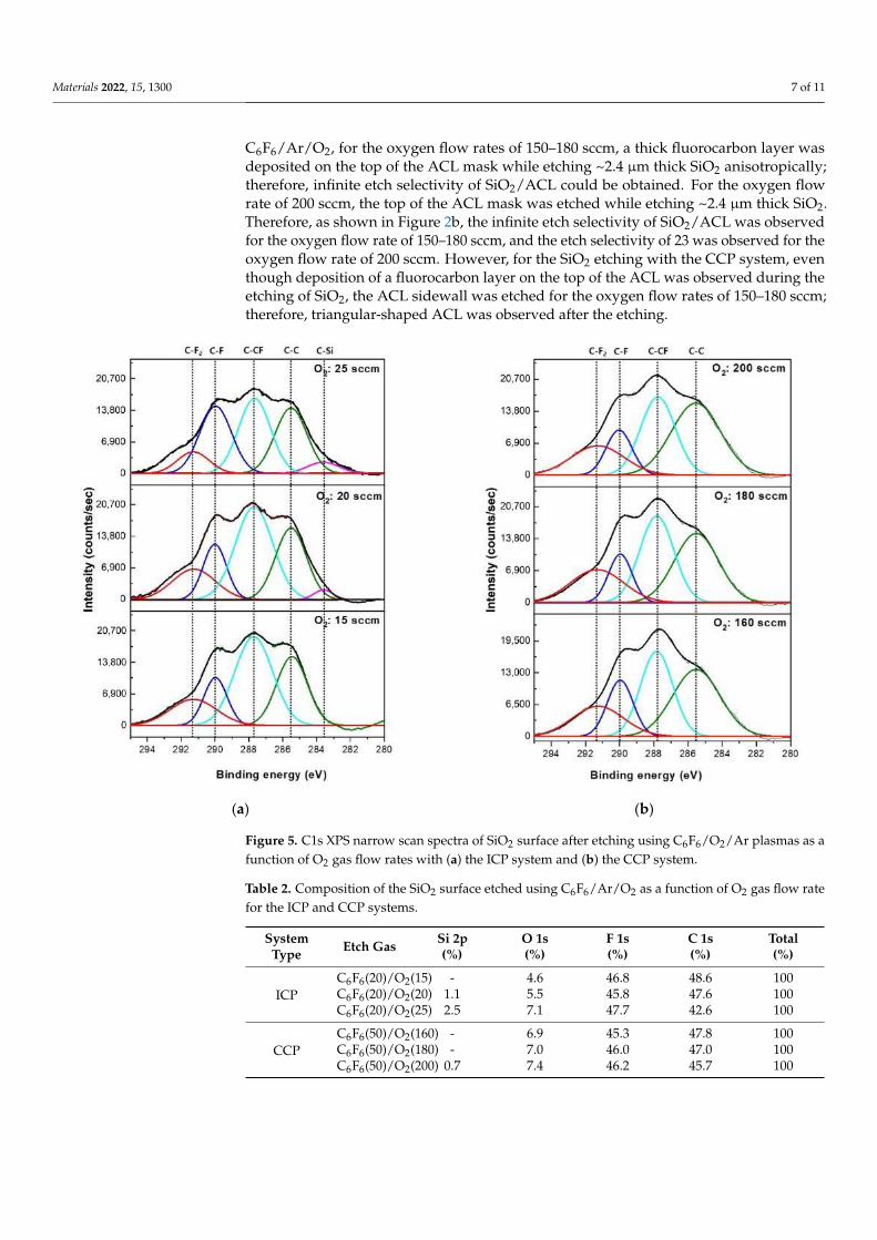
Figure 5 shows the XPS narrow scan data of C 1s on the SiO2 surfaces etched withC6F6/Ar/O2 for different oxygen flow rates for (a) the ICP system with C6F6(20)/Ar(10)/O2(15–25 sccm) and (b) the CCP system with C6F6(50)/Ar(150)/O2(160~200 sccm). The otherconditions are the same as those in Figure 2. The carbon bonding peaks such as C–C(285.5 eV), C–CF (287.8 eV), C–F (290.0 eV), and C–F2 (291.3 eV) could be observed [21]. Forthe ICP system, as shown in Figure 5a, the increase in oxygen flow rate from 15 to 25 sccmdecreased C–C bonding and C–CF bonding slightly possibly due to the greater dissociationof species from the plasmas as shown in Figure 4a. In the case of the CCP system, theincrease in oxygen flow rate from 160 to 200 sccm did not change the carbon bondingpeaks on the SiO2 surface noticeably possibly due to no significant change of radical ratioswith increasing oxygen flow rate as shown in Figure 4b. When C 1s bonding peaks onthe etched SiO2 surfaces between the ICP system and the CCP systems are compared, theSiO2 surfaces etched by the CCP system show slightly higher C-CF bonding intensitiescompared to those by the ICP system. Table 2 shows the composition of the SiO2 surfaceetched using C6F6/Ar/O2 as a function of O2 gas flow rates for the ICP and CCP systemsfor the conditions in Figure 5. As shown in Table 2, even though the ratio of C6F6/O2in the gas mixture was much higher for the SiO2 etching using the CCP system, similarcompositions of fluorocarbon polymer layers were observed between the ICP system andthe CCP system on the etched SiO2 surfaces; however, a more significant increase in Sipercentage (0% to 2.5% for ICP and 0% to 0.7% for CCP) and a more significant decrease inC percentage (48.6% to 42.6% for ICP and 47.8% to 45.7% for CCP) were observed on theetched SiO2 surfaces for the ICP system compared to those for the CCP system, indicatingthinner fluorocarbon layers on the SiO2 surface etched by the ICP system, which couldincrease SiO2 etch rate with increasing oxygen flow rate. In fact, the SiO2 etch rate wasincreased with oxygen flow rate from 15 to 22.5 sccm for the ICP system, while that for theCCP system was almost saturated with increasing oxygen flow rate from 150 to 200 sccm.
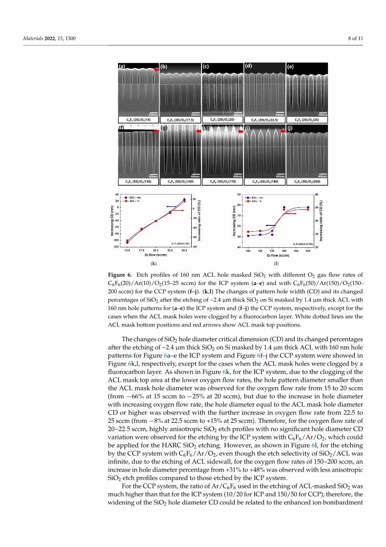
The etch profiles of 160 nm ACL hole masked SiO2 with different O2 gas flow rates ofC6F6(20)/Ar(10)/O2(15–25 sccm) for the ICP system are shown in Figure 6a–e, and thosewith C6F6(50)/Ar(150)/O2(150–200 sccm) for the CCP system are shown in Figure 6f–j.White dotted lines are the ACL mask bottom positions and red arrows show ACL mask toppositions. For the ICP etching with C6F6/Ar/O2, for 15–17.5 sccm of oxygen flow rate, theACL mask was clogged by the fluorocarbon layer after etching 1.4–2.0 µm depth of SiO2.After using the oxygen flow rate of 20 sccm or higher, ~2.4 µm thick SiO2 could be fullyetched with highly anisotropic etch profiles even though the etched amount of ACL maskwas increased with the increase in oxygen flow rate. In the case of the CCP etching with
Materials 2022, 15, 1300 7 of 11
C6F6/Ar/O2, for the oxygen flow rates of 150–180 sccm, a thick fluorocarbon layer wasdeposited on the top of the ACL mask while etching ~2.4 µm thick SiO2 anisotropically;therefore, infinite etch selectivity of SiO2/ACL could be obtained. For the oxygen flowrate of 200 sccm, the top of the ACL mask was etched while etching ~2.4 µm thick SiO2.Therefore, as shown in Figure 2b, the infinite etch selectivity of SiO2/ACL was observedfor the oxygen flow rate of 150–180 sccm, and the etch selectivity of 23 was observed for theoxygen flow rate of 200 sccm. However, for the SiO2 etching with the CCP system, eventhough deposition of a fluorocarbon layer on the top of the ACL was observed during theetching of SiO2, the ACL sidewall was etched for the oxygen flow rates of 150–180 sccm;therefore, triangular-shaped ACL was observed after the etching.
Materials 2021, 14, x FOR PEER REVIEW 7 of 13
peaks on the SiO2 surface noticeably possibly due to no significant change of radical ratios
with increasing oxygen flow rate as shown in Figure 4b. When C 1s bonding peaks on the
etched SiO2 surfaces between the ICP system and the CCP systems are compared, the SiO2
surfaces etched by the CCP system show slightly higher C-CF bonding intensities com-
pared to those by the ICP system. Table 2 shows the composition of the SiO2 surface etched
using C6F6/Ar/O2 as a function of O2 gas flow rates for the ICP and CCP systems for the
conditions in Figure 5. As shown in Table 2, even though the ratio of C6F6/O2 in the gas
mixture was much higher for the SiO2 etching using the CCP system, similar compositions
of fluorocarbon polymer layers were observed between the ICP system and the CCP sys-
tem on the etched SiO2 surfaces; however, a more significant increase in Si percentage (0%
to 2.5% for ICP and 0% to 0.7% for CCP) and a more significant decrease in C percentage
(48.6% to 42.6% for ICP and 47.8% to 45.7% for CCP) were observed on the etched SiO2
surfaces for the ICP system compared to those for the CCP system, indicating thinner flu-
orocarbon layers on the SiO2 surface etched by the ICP system, which could increase SiO2
etch rate with increasing oxygen flow rate. In fact, the SiO2 etch rate was increased with
oxygen flow rate from 15 to 22.5 sccm for the ICP system, while that for the CCP system
was almost saturated with increasing oxygen flow rate from 150 to 200 sccm.
(a) (b)
Figure 5. C1s XPS narrow scan spectra of SiO2 surface after etching using C6F6/O2/Ar plasmas as a
function of O2 gas flow rates with (a) the ICP system and (b) the CCP system.
Figure 5. C1s XPS narrow scan spectra of SiO2 surface after etching using C6F6/O2/Ar plasmas as afunction of O2 gas flow rates with (a) the ICP system and (b) the CCP system.
Table 2. Composition of the SiO2 surface etched using C6F6/Ar/O2 as a function of O2 gas flow ratefor the ICP and CCP systems.
SystemType Etch Gas Si 2p
(%)O 1s(%)
F 1s(%)
C 1s(%)
Total(%)
ICPC6F6(20)/O2(15) - 4.6 46.8 48.6 100C6F6(20)/O2(20) 1.1 5.5 45.8 47.6 100C6F6(20)/O2(25) 2.5 7.1 47.7 42.6 100
CCPC6F6(50)/O2(160) - 6.9 45.3 47.8 100C6F6(50)/O2(180) - 7.0 46.0 47.0 100C6F6(50)/O2(200) 0.7 7.4 46.2 45.7 100
Materials 2022, 15, 1300 8 of 11Materials 2021, 14, x FOR PEER REVIEW 9 of 13
(k) (l)
Figure 6. Etch profiles of 160 nm ACL hole masked SiO2 with different O2 gas flow rates of
C6F6(20)/Ar(10)/O2(15–25 sccm) for the ICP system (a–e) and with C6F6(50)/Ar(150)/O2(150–200 sccm)
for the CCP system (f–j). (k,l) The changes of pattern hole width (CD) and its changed percentages
of SiO2 after the etching of ~2.4 μm thick SiO2 on Si masked by 1.4 μm thick ACL with 160 nm hole
patterns for (a–e) the ICP system and (f–j) the CCP system, respectively, except for the cases when
the ACL mask holes were clogged by a fluorocarbon layer. White dotted lines are the ACL mask
bottom positions and red arrows show ACL mask top positions.
The changes of SiO2 hole diameter critical dimension (CD) and its changed percent-
ages after the etching of ~2.4 μm thick SiO2 on Si masked by 1.4 μm thick ACL with 160
nm hole patterns for Figure 6a–e the ICP system and Figure 6f–j the CCP system were
showed in Figure 6k,l, respectively, except for the cases when the ACL mask holes were
clogged by a fluorocarbon layer. As shown in Figure 6k, for the ICP system, due to the
clogging of the ACL mask top area at the lower oxygen flow rates, the hole pattern diam-
eter smaller than the ACL mask hole diameter was observed for the oxygen flow rate from
15 to 20 sccm (from −66% at 15 sccm to −25% at 20 sccm), but due to the increase in hole
diameter with increasing oxygen flow rate, the hole diameter equal to the ACL mask hole
diameter CD or higher was observed with the further increase in oxygen flow rate from
22.5 to 25 sccm (from −8% at 22.5 sccm to +15% at 25 sccm). Therefore, for the oxygen flow
rate of 20~22.5 sccm, highly anisotropic SiO2 etch profiles with no significant hole diameter
Figure 6. Etch profiles of 160 nm ACL hole masked SiO2 with different O2 gas flow rates ofC6F6(20)/Ar(10)/O2(15–25 sccm) for the ICP system (a–e) and with C6F6(50)/Ar(150)/O2(150–200 sccm) for the CCP system (f–j). (k,l) The changes of pattern hole width (CD) and its changedpercentages of SiO2 after the etching of ~2.4 µm thick SiO2 on Si masked by 1.4 µm thick ACL with160 nm hole patterns for (a–e) the ICP system and (f–j) the CCP system, respectively, except for thecases when the ACL mask holes were clogged by a fluorocarbon layer. White dotted lines are theACL mask bottom positions and red arrows show ACL mask top positions.
The changes of SiO2 hole diameter critical dimension (CD) and its changed percentagesafter the etching of ~2.4 µm thick SiO2 on Si masked by 1.4 µm thick ACL with 160 nm holepatterns for Figure 6a–e the ICP system and Figure 6f–j the CCP system were showed inFigure 6k,l, respectively, except for the cases when the ACL mask holes were clogged by afluorocarbon layer. As shown in Figure 6k, for the ICP system, due to the clogging of theACL mask top area at the lower oxygen flow rates, the hole pattern diameter smaller thanthe ACL mask hole diameter was observed for the oxygen flow rate from 15 to 20 sccm(from −66% at 15 sccm to −25% at 20 sccm), but due to the increase in hole diameterwith increasing oxygen flow rate, the hole diameter equal to the ACL mask hole diameterCD or higher was observed with the further increase in oxygen flow rate from 22.5 to25 sccm (from −8% at 22.5 sccm to +15% at 25 sccm). Therefore, for the oxygen flow rate of20~22.5 sccm, highly anisotropic SiO2 etch profiles with no significant hole diameter CDvariation were observed for the etching by the ICP system with C6F6/Ar/O2, which couldbe applied for the HARC SiO2 etching. However, as shown in Figure 6l, for the etchingby the CCP system with C6F6/Ar/O2, even though the etch selectivity of SiO2/ACL wasinfinite, due to the etching of ACL sidewall, for the oxygen flow rates of 150~200 sccm, anincrease in hole diameter percentage from +31% to +48% was observed with less anisotropicSiO2 etch profiles compared to those etched by the ICP system.
For the CCP system, the ratio of Ar/C6F6 used in the etching of ACL-masked SiO2 wasmuch higher than that for the ICP system (10/20 for ICP and 150/50 for CCP); therefore, thewidening of the SiO2 hole diameter CD could be related to the enhanced ion bombardment
Materials 2022, 15, 1300 9 of 11
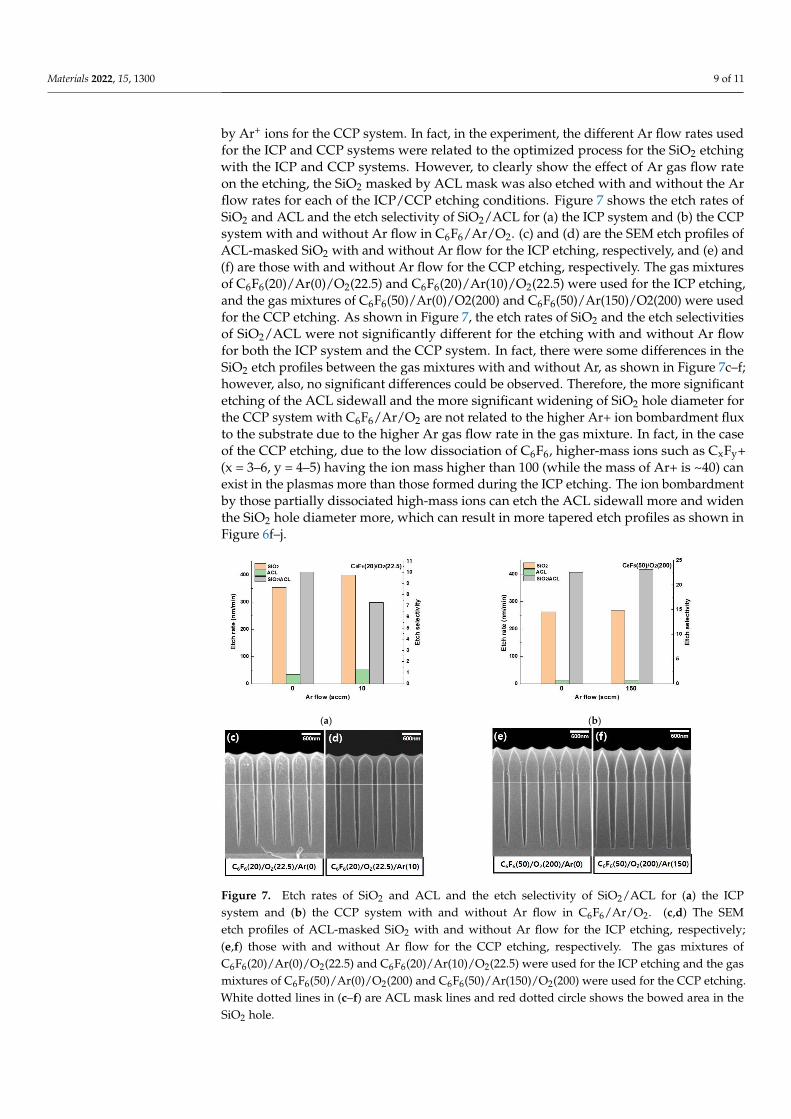
by Ar+ ions for the CCP system. In fact, in the experiment, the different Ar flow rates usedfor the ICP and CCP systems were related to the optimized process for the SiO2 etchingwith the ICP and CCP systems. However, to clearly show the effect of Ar gas flow rateon the etching, the SiO2 masked by ACL mask was also etched with and without the Arflow rates for each of the ICP/CCP etching conditions. Figure 7 shows the etch rates ofSiO2 and ACL and the etch selectivity of SiO2/ACL for (a) the ICP system and (b) the CCPsystem with and without Ar flow in C6F6/Ar/O2. (c) and (d) are the SEM etch profiles ofACL-masked SiO2 with and without Ar flow for the ICP etching, respectively, and (e) and(f) are those with and without Ar flow for the CCP etching, respectively. The gas mixturesof C6F6(20)/Ar(0)/O2(22.5) and C6F6(20)/Ar(10)/O2(22.5) were used for the ICP etching,and the gas mixtures of C6F6(50)/Ar(0)/O2(200) and C6F6(50)/Ar(150)/O2(200) were usedfor the CCP etching. As shown in Figure 7, the etch rates of SiO2 and the etch selectivitiesof SiO2/ACL were not significantly different for the etching with and without Ar flowfor both the ICP system and the CCP system. In fact, there were some differences in theSiO2 etch profiles between the gas mixtures with and without Ar, as shown in Figure 7c–f;however, also, no significant differences could be observed. Therefore, the more significantetching of the ACL sidewall and the more significant widening of SiO2 hole diameter forthe CCP system with C6F6/Ar/O2 are not related to the higher Ar+ ion bombardment fluxto the substrate due to the higher Ar gas flow rate in the gas mixture. In fact, in the caseof the CCP etching, due to the low dissociation of C6F6, higher-mass ions such as CxFy+(x = 3–6, y = 4–5) having the ion mass higher than 100 (while the mass of Ar+ is ~40) canexist in the plasmas more than those formed during the ICP etching. The ion bombardmentby those partially dissociated high-mass ions can etch the ACL sidewall more and widenthe SiO2 hole diameter more, which can result in more tapered etch profiles as shown inFigure 6f–j.
Materials 2021, 14, x FOR PEER REVIEW 11 of 13
(a) (b)
Figure 7. Etch rates of SiO2 and ACL and the etch selectivity of SiO2/ACL for (a) the ICP system and
(b) the CCP system with and without Ar flow in C6F6/Ar/O2. (c,d) The SEM etch profiles of ACL-
masked SiO2 with and without Ar flow for the ICP etching, respectively; (e,f) those with and without
Ar flow for the CCP etching, respectively. The gas mixtures of C6F6(20)/Ar(0)/O2(22.5) and
C6F6(20)/Ar(10)/O2(22.5) were used for the ICP etching and the gas mixtures of
C6F6(50)/Ar(0)/O2(200) and C6F6(50)/Ar(150)/O2(200) were used for the CCP etching. White dotted
lines in (c–f) are ACL mask lines and red dotted circle shows the bowed area in the SiO2 hole.
Figure 7. Etch rates of SiO2 and ACL and the etch selectivity of SiO2/ACL for (a) the ICPsystem and (b) the CCP system with and without Ar flow in C6F6/Ar/O2. (c,d) The SEMetch profiles of ACL-masked SiO2 with and without Ar flow for the ICP etching, respectively;(e,f) those with and without Ar flow for the CCP etching, respectively. The gas mixtures ofC6F6(20)/Ar(0)/O2(22.5) and C6F6(20)/Ar(10)/O2(22.5) were used for the ICP etching and the gasmixtures of C6F6(50)/Ar(0)/O2(200) and C6F6(50)/Ar(150)/O2(200) were used for the CCP etching.White dotted lines in (c–f) are ACL mask lines and red dotted circle shows the bowed area in theSiO2 hole.
Materials 2022, 15, 1300 10 of 11
4. Conclusions
In this study, using a perfluorocarbon (PFC) gas having a high C/F ratio of C6F6 andlow GWP of 7, the differences in the plasma characteristics and the etch characteristicswere compared between an ICP system and a CCP system. In addition, the possibility ofusing an ICP system instead of a conventional CCP system in HARC SiO2 etching maskedwith ACL was investigated for C6F6/Ar/O2 gas mixtures. It was found that, due to thehigher dissociation of C6F6 and O2 for the ICP system compared to the CCP system, theSiO2 etching required a much lower ratio of O2/C6F6 while showing a higher maximumSiO2 etch rate and lower etch selectivity. However, in the case of the ICP etching withC6F6, even though the etch selectivity was much lower than that of the CCP etching withC6F6, due to less heavy-mass-ion bombardment in addition to an adequate fluorocarbonlayer formation on the substrate, highly anisotropic SiO2 etch profiles could be obtained atcertain oxygen gas flow rates added to C6F6. The high gas dissociation of the ICP systemcould be identified from higher densities of CF2, CO, and C2 radicals in the ICP systemcompared to the CCP system. It is believed that the ICP system could be also applied tothe HARC SiO2 etching with higher etch rates and vertical etch profiles by using high C/Fratio PFCs and by controlling etch parameters adequately.
Author Contributions: Conceptualization, D.S. and G.Y.; methodology, D.S., L.W., H.T., D.K. andG.Y.; investigation, D.S., L.W., H.T. and D.K.; data curation, L.W., H.T. and H.L.; writing—originaldraft preparation, D.S., L.W. and D.K.; writing—review and editing, G.Y.; supervision, G.Y.; projectadministration, G.Y. All authors have read and agreed to the published version of the manuscript.
Funding: This work was supported by the Korea Institute of Energy Technology Evaluation andPlanning (KETEP) and the Ministry of Trade, Industry & Energy (MOTIE) of the Republic of Korea(No. 20202010100020), and this work was supported by the National Research Foundation of Korea(NRF) grant funded by the Korea government (MSIT) (No. NRF-2020R1A2C2007532).
Institutional Review Board Statement: Not applicable.
Informed Consent Statement: Not applicable.
Data Availability Statement: All the data is available within the manuscript.
Conflicts of Interest: Not applicable.
References1. Kwon, B.; Kim, J.; Lee, N.; Shon, J. Ultrahigh selective etching of SiO2 using an amorphous carbon mask in dual-frequency
capacitively coupled C4F8/CH2F2/O2/Ar plasmas. J. Electrochem. Soc. 2010, 157, D135–D141. [CrossRef]2. Son, J.; Efremov, A.; Chun, I.; Yeom, G.; Kwon, K. On the LPCVD-formed SiO2 Etching mechanism in CF4/Ar/O2 inductively
coupled plasmas: Effects of gas mixing ratios and gas pressure. Plasma Chem. Plasma Process. 2014, 34, 239–257. [CrossRef]3. Lee, H.; Yang, K.; Kim, S.; Shin, Y.; Suh, D.; Song, H.; Lee, N.; Yeom, G. SiO2 etch characteristics and environmental impact of
Ar/C3F6O chemistry. J. Vac. Sci. Technol. A 2018, 35, 061306. [CrossRef]4. Samukawa, S.; Mukai, T. High-performance silicon dioxide etching for less than 0.1-mm-high-aspect contact holes. J. Vac. Sci.
Technol. B 2000, 18, 166–171. [CrossRef]5. Huang, S.; Huard, C.; Shim, S.; Nam, S.; Song, I.; Lu, S.; Kushner, M. Plasma etching of high aspect ratio features in SiO2 using
Ar/C4F8/O2 mixtures: A computational investigation. J. Vac. Sci. Technol. A 2019, 37, 031304. [CrossRef]6. Cha, T.; Kim, Y.; Lee, S.; Cho, Y.; Chae, H. Low-global warming potential fluoroether compounds for plasma etching of SiO2 and
Si3N4 layers. J. Vac. Sci. Technol. A 2019, 37, 051302. [CrossRef]7. Cho, C.; You, K.; Kim, S.; Lee, Y.; Lee, J.; You, S. Characterization of SiO2 etching profiles in pulse-modulated capacitively coupled
plasmas. Materials 2021, 14, 5036. [CrossRef] [PubMed]8. Huang, S.; Shim, S.; Nam, S.K.; Kushner, M. Pattern dependent profile distortion during plasma etching of high aspect ratio
features in SiO2. J. Vac. Sci. Technol. 2020, 38, 023001. [CrossRef]9. Samukawa, S. High-performance and damage-free plasma etching processes for future ULSI patterning. Microelectron. Eng. 2000,
53, 69–76. [CrossRef]10. Nojiri, K. Handbook of Dry Etching Technology for Semiconductors; Springer: Berlin/Heidelberg, Germany, 2015.11. Li, X.; Hua, X.; Oehrlein, G. Fluorocarbon-based plasma etching of comparison of and discharges. J. Vac. Sci. Technol. A 2002,
20, 2052. [CrossRef]
Materials 2022, 15, 1300 11 of 11
12. Kakamura, S.; ITano, M.; Aoyama, H.; Shimahara, K.; Yokoyama, S.; Hirose, M. Comparative Studies of PerfluorocarbonAlternative Gas Plasmas for Contact Hole Etch. Jpn. J. Appl. Phys. 2003, 42, 5759–5764. [CrossRef]
13. Kim, J.; Park, J.; Kim, C. SiO2 etching in inductively coupled plasmas using heptafluoroisopropyl methyl ether and 1,1,2,2-tetrafluoroethyl 2,2,2-trifluoroethyl ether. Appl. Surf. Sci. 2020, 508, 144787. [CrossRef]
14. Kim, J.; Park, J.; Kim, C. Angular dependence of SiO2 etching in plasmas containing heptafluoropropyl methyl ether. Thin SolidFilms 2019, 669, 262–268. [CrossRef]
15. Betowski, D.; Bevington, C.; Allison, T. Estimation of Radiative Efficiency of Chemicals with Potentially Significant GlobalWarming Potential. Environ. Sci. Technol. 2016, 50, 790–797. [CrossRef] [PubMed]
16. Siepielski, A.; Morrissey, M.; Bruno, M.; Carlson, S.; Caruso, C.; Clegg, S.; Coulson, T.; DiBattista, J.; Gotanda, K.; Francis, C.; et al.Precipitation drives global variation in natural selection. Science 2017, 355, 959–962. [CrossRef] [PubMed]
17. Schipper, E. Conceptual history of adaptation in the UNFCCC process. Reciel 2006, 15, 82–92. [CrossRef]18. Sung, D.; Tak, H.; Kim, D.; Yeom, G. A comparative study of Cx(X = 4,5,7)F8 plasmas for dry etch processing. Mater. Express 2020,
10, 903–908. [CrossRef]19. Labelle, C.; Gleason, K. Pulsed Plasma Deposition from 1,1,2,2-Tetrafluoroethane by Electron Cyclotron Resonance and Conven-
tional Plasma Enhanced Chemical Vapor Deposition. J. Appl. Polym. Sci. 2001, 80, 2084–2092. [CrossRef]20. Kuboi, N.; Tatsumi, T.; Kobayashi, S.; Komachi, J.; Fukasawa, M.; Kinoshita, T.; Ansai, H. Numerical Simulation Method for
Plasma-Induced Damage Profile in SiO2 Etching. Jpn. J. Appl. Phys. 2011, 50, 116501.21. Metzler, D.; Li, C.; Engelmann, S.; Bruce, R.; Joseph, E.; Oehrlein, G. Characterizing fluorocarbon assisted atomic layer etching of
Si using cyclic Ar/C4F8 and Ar/CHF3 plasma. J. Chem. Phys. 2017, 146, 052801. [CrossRef]