installing the network 9000 routing hub
TRANSCRIPT
Installing the Network 9000Routing Hub
!Installation and servicing of the chassis and allmodules should be performed only by qualified,trained service personnel.
Xyplex, Incorporated295 Foster Street
Littleton, MA 01460
1-800-435-7997 (U.S.A)+508-264-9903 (International)
[email protected] (Internet)451-0068A
EFFECTIVE PAGES
This manual contains 53 pages consisting of the following:
Issue: Original Date: September, 1992
Page(s) Issue
i through vi . . . . Original1-1 through 1-12 . . . Original2-1 through 2-6 . . . Original3-1 through 3-11 . . . Original4-1 through 4-3 . . . OriginalA-1 . . . . . . OriginalB-1 . . . . . . OriginalC-1 . . . . . . OriginalD-1 through D-7 . . . OriginalG-1 through G-5 . . . Original
CAUTION: The modules that are intended to be installed or serviced in the Model N9-9003-001, N9-9006-001, N9-9015-001, and N9-9015-002 are limited to service personnel.
Attention: Les cartes d'extention qui sont destinee a etre installee ou entretien dans lesmodeles N9-9003-001, N9-9006-001, N9-9015-001, et N9-9015-002 est limitee aux depanneur.
Vorsicht: Die Modelle N9-9003-001, N9-9006-001, N9-9015-001, und N9-9015-002 dürfen nurvon ausgebildetem Servicepersonal installiert und gewartet werden.
DEC, VAX, VMS, DEConnect, and DECserver are trademarks of Digital Equipment Corporation.
All rights reserved. No part of this publication may be reproduced without the prior written consentof Xyplex, Inc. The information in this document is subject to change without notice and shouldnot be construed as a commitment by Xyplex, Inc. Xyplex, Inc. reserves the right to revise thispublication, and to make changes in content from time to time, without obligation to providenotification of such revision or changes. Xyplex, Inc. assumes no responsibility for errors thatmay appear in this document.
Copyright © 1993 by Xyplex, Inc. Printed in U.S.A.
2
Table of Contents
Section Page Number
Preface
Chapter 1 - Introducing the Network 9000 Multimedia Intelligent Hub
1.1 Overview. . . . . . . . . . . . . . . . . . . . . . . . . . . . . . . . . . . . . . . . . . . . . . . . . . . . . . . . . . . . . . . . . . . . . . . . . . . . . . . .71.2 Network 9000 Architecture... . . . . . . . . . . . . . . . . . . . . . . . . . . . . . . . . . . . . . . . . . . . . . . . . . . . . . . . . .7
1.2.1 Network 9000 Multimedia Midplane . . . . . . . . . . . . . . . . . . . . . . . . . . . . . . . . . . . . . . . . . . . . . . . .81.2.3 Power Supply Modules.. . . . . . . . . . . . . . . . . . . . . . . . . . . . . . . . . . . . . . . . . . . . . . . . . . . . . . . . . . . . . . . .101.2.4 AC Power Input Module... . . . . . . . . . . . . . . . . . . . . . . . . . . . . . . . . . . . . . . . . . . . . . . . . . . . . . . . . . . . . .10
1.3. Network 9000 System Features............................................................111.3.1 Hot Swap. . . . . . . . . . . . . . . . . . . . . . . . . . . . . . . . . . . . . . . . . . . . . . . . . . . . . . . . . . . . . . . . . . . . . . . . . . . . . . . . .111.3.2 Software Image Loading.. . . . . . . . . . . . . . . . . . . . . . . . . . . . . . . . . . . . . . . . . . . . . . . . . . . . . . . . . . . . .111.3.3 Parameter Storage and Loading.... . . . . . . . . . . . . . . . . . . . . . . . . . . . . . . . . . . . . . . . . . . . . . . . . .121.3.4 Remote Device Management.. . . . . . . . . . . . . . . . . . . . . . . . . . . . . . . . . . . . . . . . . . . . . . . . . . . . . . . .13
1.4 Network 9000 Communication Options..................................................141.4.1 10Base-T/10Base-F (FOIRL) Repeaters.............................................141.4.2 Enhanced Management Card.. . . . . . . . . . . . . . . . . . . . . . . . . . . . . . . . . . . . . . . . . . . . . . . . . . . . . . .141.4.3 Internetworking . . . . . . . . . . . . . . . . . . . . . . . . . . . . . . . . . . . . . . . . . . . . . . . . . . . . . . . . . . . . . . . . . . . . . . .151.4.4 Terminal Server. . . . . . . . . . . . . . . . . . . . . . . . . . . . . . . . . . . . . . . . . . . . . . . . . . . . . . . . . . . . . . . . . . . . . . .161.4.5 MAXserver Adaptor I/O Module..... . . . . . . . . . . . . . . . . . . . . . . . . . . . . . . . . . . . . . . . . . . . . . . . . .16
Chapter 2 - Installing the Network 9000 Chassis
2.1 General . . . . . . . . . . . . . . . . . . . . . . . . . . . . . . . . . . . . . . . . . . . . . . . . . . . . . . . . . . . . . . . . . . . . . . . . . . . . . . . . . . . . . .192.2 Tools Required. . . . . . . . . . . . . . . . . . . . . . . . . . . . . . . . . . . . . . . . . . . . . . . . . . . . . . . . . . . . . . . . . . . . . . . . . . . . . .192.3 Site Preparation.. . . . . . . . . . . . . . . . . . . . . . . . . . . . . . . . . . . . . . . . . . . . . . . . . . . . . . . . . . . . . . . . . . . . . . . . . . . .192.4 Unpacking and Inspecting the Hardware Kit...........................................202.5 Mounting. . . . . . . . . . . . . . . . . . . . . . . . . . . . . . . . . . . . . . . . . . . . . . . . . . . . . . . . . . . . . . . . . . . . . . . . . . . . . . . . . . . .22
2.5.1 General . . . . . . . . . . . . . . . . . . . . . . . . . . . . . . . . . . . . . . . . . . . . . . . . . . . . . . . . . . . . . . . . . . . . . . . . . . . . . . . . . .222.5.2 Rack Mount Installation.. . . . . . . . . . . . . . . . . . . . . . . . . . . . . . . . . . . . . . . . . . . . . . . . . . . . . . . . . . . . .222.5.3 Stand-Alone Installation . . . . . . . . . . . . . . . . . . . . . . . . . . . . . . . . . . . . . . . . . . . . . . . . . . . . . . . . . . . . .24
2.6 Additional Installation Activities.... . . . . . . . . . . . . . . . . . . . . . . . . . . . . . . . . . . . . . . . . . . . . . . . . . . . .24
Chapter 3 - Power Supply, Fans, and AC Input Modules
3.1 General . . . . . . . . . . . . . . . . . . . . . . . . . . . . . . . . . . . . . . . . . . . . . . . . . . . . . . . . . . . . . . . . . . . . . . . . . . . . . . . . . . . . . .253.2 Power Supply Modules . . . . . . . . . . . . . . . . . . . . . . . . . . . . . . . . . . . . . . . . . . . . . . . . . . . . . . . . . . . . . . . . . . . . .25
3.2.1 Installing and Removing Power Supply Modules . . . . . . . . . . . . . . . . . . . . . . . . . . . . . . . . .283.3 AC Power Input Module.. . . . . . . . . . . . . . . . . . . . . . . . . . . . . . . . . . . . . . . . . . . . . . . . . . . . . . . . . . . . . . . . . . .31
3.3.1 Connecting AC Power . . . . . . . . . . . . . . . . . . . . . . . . . . . . . . . . . . . . . . . . . . . . . . . . . . . . . . . . . . . . . . . . .313.3.2 Installing and Removing the AC Power Input Module............................32
3.4 Fan Trays. . . . . . . . . . . . . . . . . . . . . . . . . . . . . . . . . . . . . . . . . . . . . . . . . . . . . . . . . . . . . . . . . . . . . . . . . . . . . . . . . . .33
Section Page Number
Chapter 4 - Installing and Removing Processor and I/O Modules
4.1 General . . . . . . . . . . . . . . . . . . . . . . . . . . . . . . . . . . . . . . . . . . . . . . . . . . . . . . . . . . . . . . . . . . . . . . . . . . . . . . . . . . . . . .364.2 Installing and Removing Modules . . . . . . . . . . . . . . . . . . . . . . . . . . . . . . . . . . . . . . . . . . . . . . . . . . . . . .36
Appendix A - Specifications
Appendix B - Power Supply Configuration Worksheet
Appendix C - Slot Ethernet Addresses
Glossary
Preface
How To Use This Guide
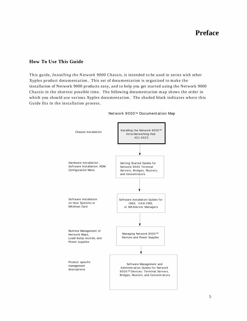
This guide, Installing the Network 9000 Chassis, is intended to be used in series with otherXyplex product documentation. This set of documentation is organized to make theinstallation of Network 9000 products easy, and to help you get started using the Network 9000Chassis in the shortest possible time. The following documentation map shows the order inwhich you should use various Xyplex documentation. The shaded block indicates where thisGuide fits in the installation process.
Installing the Network 9000™ Intra-Networking Hub
451-0023
Getting Started Guides for Network 9000 Terminal Servers, Bridges, Routers, and Concentrators
Network 9000™ Documentation Map
Managing Network 9000™ Devices and Power Supples
Software Installation Guides for UNIX, VAX/VMS,
or MAXserver Managers
Hardware Installation , Software Installation, ROM Configuration Menu
Chassis Installation
Software Installation on Host Systems or MAXman Card
Runtime Management of Network Maps, Load/dump records, and Power supplies
Software Management and Administration Guides for Network 9000™ Devices: Terminal Servers, Bridges, Routers, and Concentrators
Product specific management descriptions
5
What this Guide Covers
This guide covers installation of the Xyplex Network 9000 Chassis, power supplies, fanmodules, and the available product modules and cabling options.
This guide is organized as follows:
PrefaceChapter 1 - Introducing the Network 9000 Multimedia Intelligent HubChapter 2 - Installing the Network 9000 ChassisChapter 3 - Power Supply, Fans, and AC Input ModulesChapter 4 - Installing and Removing Processor and I/O ModulesAppendix A - SpecificationsAppendix C - Slot Ethernet AddressesGlossary
Chapter 1: Introducing the Network 9000 Intra-Networking Hub, summarizes the features ofthe Network 9000 Hub, and briefly describes how you can use the Hub and functional options tobuild a network.
Chapter 2: Installing the Network 9000 Chassis, describes the hardware installationprocedures. These procedures include:
Site PreparationUnpacking and InspectionMountingConnecting AC Power
Chapter 3: Power Supply, Fans, and AC Input Modules, describes the power supply redundancyfeatures and how to install or remove power supply, fan trays, and ac input modules. Thischapter also describes controls and indicators of these items, and the steps to take if youencounter a hardware problem.
Chapter 4: Installing and Removing Processor and I/O Modules, describes the generalprocedure and considerations for installing and removing/replacing all function card andI/O card options.
Appendix A, Specifications, lists the specifications of the chassis, power supplies, etc.
Appendix B, Slot Ethernet Addresses, shows you how to calculate the Ethernet address for eachdevice that is installed in a Network 9000 chassis.
The Glossary defines some commonly used terms in Network 9000 documentation, includingthis manual.
6
Chapter 1
Introducing the Network 9000Routing Hub
1.1 Overview
The Network 9000 Routing Hub consists of a family of chassis, processor and I/O modules,and power supply modules which provide media connectivity, internetworking, andcommunication server functions. The Network 9000 Hub provides desktop and backboneconnections to Ethernet/IEEE 802.3, IEEE 802.5 Token Ring, and FDDI networks. TheNetwork 9000 Hub delivers cost effective desktop connections for users of local and remoteresources. This chapter covers the basic features of the hub and options that are available atproduct introduction.
1.2 Network 9000 Architecture
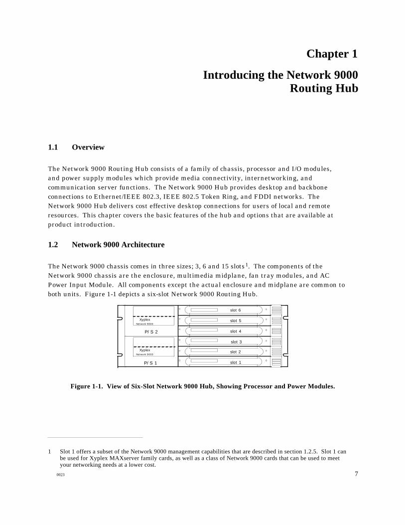
The Network 9000 chassis comes in three sizes; 3, 6 and 15 slots1. The components of theNetwork 9000 chassis are the enclosure, multimedia midplane, fan tray modules, and ACPower Input Module. All components except the actual enclosure and midplane are common toboth units. Figure 1-1 depicts a six-slot Network 9000 Routing Hub.
XyplexNetwork 9000
XyplexNetwork 9000
slot 1
slot 2
slot 3
slot 4
slot 5
slot 6
P/S 1
P/S 2
Figure 1-1. View of Six-Slot Network 9000 Hub, Showing Processor and Power Modules.
1 Slot 1 offers a subset of the Network 9000 management capabilities that are described in section 1.2.5. Slot 1 canbe used for Xyplex MAXserver family cards, as well as a class of Network 9000 cards that can be used to meetyour networking needs at a lower cost.
0023 7

Introducing the Network 9000 Routing Hub
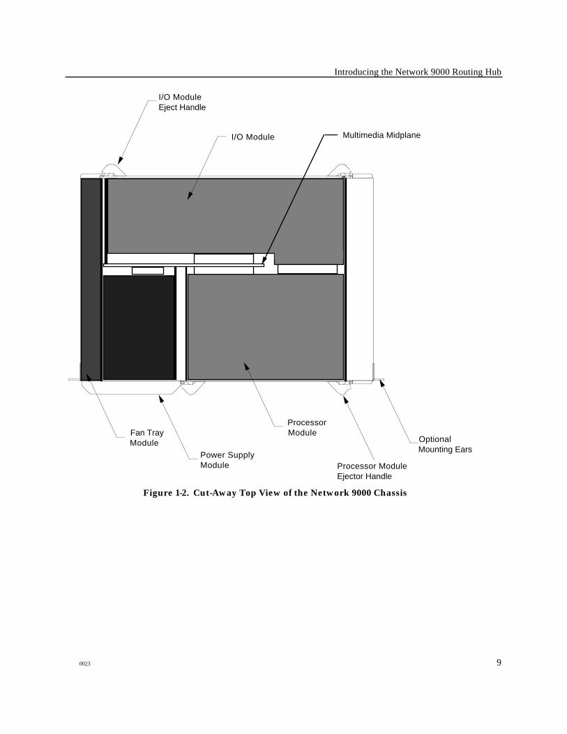
A variety of communications options are provided by Xyplex-supplied products, which consistof the processor and I/O modules (Figure 1-1 depicts Network 9000 Hub processor modules).You install product modules and power supply modules into the appropriate locations in theNetwork 9000 chassis (see Figure 1-2). The Network 9000 architecture provides you with theflexibility to choose from a variety of Xyplex product modules, so you can easily customize yourconfiguration for current needs without restricting your network growth. These optionsinclude: multi-protocol terminal servers, remote and local bridge/routers, 10Base-T/10Base-FL (FOIRL) concentrators, FDDI-to-Ethernet bridge/routers, and token-ring concentrators.An adaptor module allows you to use cards from the Xyplex MAXserver product family with theNetwork 9000 Hub.
You can also choose from a family of power supply modules, including managed andunmanaged power supplies. Managed power supplies are designed to provide status informationover the network, and can respond to certain commands entered by a network manager. TheNetwork 9000 power supply system is designed so that you can add power supplies as yournetwork needs grow. These power supplies are also designed to operate in redundant or fault-tolerant modes, by simply installing additional power supplies into the chassis.
1.2.1 Network 9000 Multimedia Midplane
The heart of the Network 9000 Hub is the multimedia midplane. It is called a midplanebecause it is located in the middle of the enclosure (instead of the front or back as with mosthubs). The midplane enhances flexibility and reliability by permitting separate I/O andprocessor modules which can be swapped independently.
The midplane supports three Ethernet LAN segments, four IEEE 802.5 Token Ring LANsegments, a dual-ring FDDI LAN segment, a local management bus (LMB), and power lines.The LMB provides a common communications channel for any native Network 9000 productmodule to use, independent of the LANs to which it may be connected. Manageable powersupplies can also connect to the LMB. As a dedicated management bus, the LMB facilitates themanagement of modules regardless of the state (off line, active, reset, loading software, etc) ofthe module.
Figure 1-2 depicts the location of the midplane in a Network 9000 chassis. As shown in Figure1-2, there are circuit boards that plug into one side of the midplane which are called calledprocessor modules. These modules hold the processing power of the product. Circuit boardswhich plug into the opposite side of the midplane are called I/O modules. These modulescontain connectors for making external connections to devices. Some products (such asterminal servers, bridge/routers, managed concentrators, etc) require both a processor and anI/O module to function. Other products (unmanaged 10Base-T or 10Base-FL/FOIRLconcentrators) require only the I/O module to function.
8 0023
Introducing the Network 9000 Routing Hub
Processor Module Ejector Handle
Optional Mounting Ears
Power Supply Module
Processor ModuleFan Tray
Module
Multimedia MidplaneI/O Module
I/O Module Eject Handle
Figure 1-2. Cut-Away Top View of the Network 9000 Chassis
0023 9
Introducing the Network 9000 Routing Hub
1.2.3 Power Supply Modules
Power is delivered to Network 9000 product modules by one or more Model P/S 130 ManagedPower Supply Modules. The Model P/S 130 managed power supply modules are 150 Watt powersupplies. Each module is hot swappable, can be configured redundantly, and is manageable.Each P/S 130 module adapts to a wide range of ac input voltage (110 to 240 Vac). Power factorcorrection has been incorporated. Redundancy is supported in N+1 fashion, that is, if twopower supplies deliver enough power then a third makes the system redundant. Load sharingis used so that no interruption of power occurs should a redundant supply fail.
☞ It is possible that you can configure options in a Network 9000 Hub so that the hub does
not operate redundantly. Use the Power Supply Configuration Worksheets containedin Appendix B to calculate power supply requirements for your Hub. You should alsorecalculate these requirements prior to adding modules to the Hub.
Each managed power supply has a microcontroller which controls and reports on its operation.The microcontroller keeps track of how much power is being output by its own supply and byany other supplies in the hub, which allows it to determine if its supply is redundant. It alsomonitors thermal limits, generating a warning if the supply is overheating. Themicrocontroller can also turn off or reset its supply. The microcontroller obtains its powerfrom the general power bus instead of its local supply, thus allowing monitoring of the supplyeven when it is turned off.
For the P/S 130 module, management information is available from front panel LEDindicators, SNMP or SHOW commands. Front panel LED indicators include a bar graph toshow power utilization, and redundancy and status LEDs. This information is also availablevia SNMP commands and from the user interface of any Network 9000 product module. SNMPand user interface commands also allow a P/S power supply module to be turned off or reset.
10 0023
Introducing the Network 9000 Routing Hub
1.2.4 AC Power Input Module
The AC input module is an I/O module that plugs into the bottom I/O module slot (slot 1) of thehub. The ac power input module includes the connection for the power cord, a circuit breakerswitch, and storage for the initialization parameters used by each functional module (this isreferred to as Control Storage; refer to section 1.3.3). It also incorporates a MAXserver adaptormodule which will be discussed in the options section.
A Redundant AC Power Input Module is available for Network 9000 fifteen-slot chassis . TheNetwork 9000 Redundant AC Power Input Module provides the means to ensure uninterruptedservice, in the event of a power system failure, when an AC circuit within a facility fails, orwhen an AC Power Input Module fails. These modules are included with the redundantversion of the Network 9000 fifteen-slot chassis, and are similar to the standard Network 9000AC Power Input Module in appearance, features, and operation.
1.2.5 Communication Options Management Capabilities
The Network 9000 product family offers you a choice of communication options which let youdecide the most cost-effective combination of performance, functionality, and managability foryour network. Xyplex categorizes Network 9000 products into two types on the basis of theirability to take advantage of some Network 9000 chassis management capabilities, which aredescribed later in this chapter, as well as their ability to connect to Ethernet segments A, B, or C.
Type 1 products are those products which must be managed using methods listed in the nextsection, other than the Network 9000 chassis management capabilities. Also, Type 1 productscan only be connected to Ethernet segment A. Network 9000 products such as the 3605 LANInterface Card (LIC) and the 6800 WAN Loader Card are Type 1 products. All MAXserverfamily cards are Type 1 products.
Type 2 products can be managed using either the Network 9000 chassis managementcapabilities or any of the other methods listed in the next section. The products can beconnected to Ethernet segments A, B, and/or C. Appendix B of this manual lists the currentlyavailable Type 1 and Type 2 products.
0023 11
Introducing the Network 9000 Routing Hub
Managing Network 9000 Products
Network managers have available to them a variety of software tools with which to manageNetwork 9000 products. Some of these tools are supplied by Xyplex; other tools are supplied byvendors such as Digital Equipment Corporation, Sun Microsystems, Inc., etc.
All products support the following network management tools:
• ControlPoint• SNMP• The DECnet Network Control Program (NCP)• DEC Terminal Server Manager (TSM)
Only Type 2 products support the following network management tool:
• Network 9000 Chassis Management Commands
Refer to the Guide to Managing Network 9000 Devices and Power Supplies for more informationabout these methods.
1.3. Network 9000 System Features
The Network 9000 Hub combined with its product modules implement the following features:
• hot swap• software image loading• parameter storage and loading• remote device management• security loading
1.3.1 Hot Swap
All processor, I/O, and fan tray modules in six and fifteen slot Network 9000 Hubs are hotswappable without disturbing any other function in the Hub. Depending on yourconfiguration, power supply modules may be hot swapped without disturbing any other functionin the Hub.
☞ Chapters 3 and 4 describe the procedures that you use to remove and replaceindividual modules, as well as some important safety considerations.
12 0023

Introducing the Network 9000 Routing Hub
1.3.2 Software Image Loading
When a processor module is plugged into the Hub it will run diagnostics then attempt to loaditself with operational software. Network 9000 product s are capable of loading from: a memorycard installed in the processor modules' memory card slot; another Network 9000 productmodule acting as a load server; a host on the network via the DEC MOP protocol, RARP/TFTP,BOOTP/TFTP, directed TFTP, or by other Xyplex products (XMOP). The network managercan select which method the product module will use to load software. The control storage on theac power input module mentioned earlier holds this loading information. The control storageis configured at the factory with a default initialization configuration for each product module(load from midplane Ethernet LAN segment A, all protocols enabled).
Three initialization configurations are available for each slot (these are referred to as primary,secondary, and tertiary initialization configurations). Each initialization configurationspecifies where the product module should to attempt to load from (e.g. Ethernet A, WANconnector 1) and which protocols to use. If loading fails based on the information in the primaryrecord then the secondary configuration is used and finally the tertiary. If all configurationsfail the product module waits briefly then retries starting with the primary configuration.
1.3.3 Parameter Storage and Loading
Each product module uses and stores two sets of parameters: initialization parameters andoperational parameters. Both types of parameters are not stored on the card itself, rather theyare stored elsewhere on the network to facilitate "hot swapping" of modules in the hub.
Initialization parameters refer to values that the product module uses during the softwareloading process. Initialization parameters include which protocols should be used to loadsoftware and operational parameters. These parameters are stored in the Control Storage ofthe ac input module of the Network 9000 chassis. You can change most of these parameters viathe product module's initialization configuration menu or by the commands listed in theGuide to Managing Network 9000 Devices and Power Supplies.
Operational parameters (e.g., those affected by DEFINE commands) affect the operation of thedevice after it has been loaded. Typically, operational parameters affect WAN or LANinterfaces, serial ports (e.g., speed, parity, character size, etc), the availability of localservices, Internet characteristics (e.g., internet-address, domain-name, subnet-mask, etc),and LAT characteristics, etc, depending on the product. You can configure the unit to load itsoperational parameters from a flash memory card, if one is available, or from a network host,called a parameter server, using the initialization configuration menu. Alternatively, youcan use DEFINE SERVER commands to change the parameter loading method (refer to theGuide to Managing Network 9000 Devices and Power Supplies for more information).
0023 13

Introducing the Network 9000 Routing Hub
The server may be configured to store parameters locally on a flash memory card, if one isavailable, on the memory card of another product module in the hub acting as a parameterserver, or remotely in a file at any properly configured parameter servers. You usecommands to change the parameter storing method. Operational parameters can be storedredundantly so that if one parameter server is not available during a reboot other parameterservers may be used.
☞ The term operational parameters is used in this guide to refer to parameters whichaffect the operation of the software after initialization. Readers of the TCP/IP-LATDocumentation Set should note that the term operational parameters is used there torefer to "temporary" parameters.
1.3.4 Remote Device Management
Remote device management allows any Type 2 product module to send a command over theLMB to another product module or managed power supply. Typically, you would use thisfeature to manage from a central location the connections to external interfaces or to internalmidplane LAN segments. You can also use remote device management to reset processormodules or power supplies.
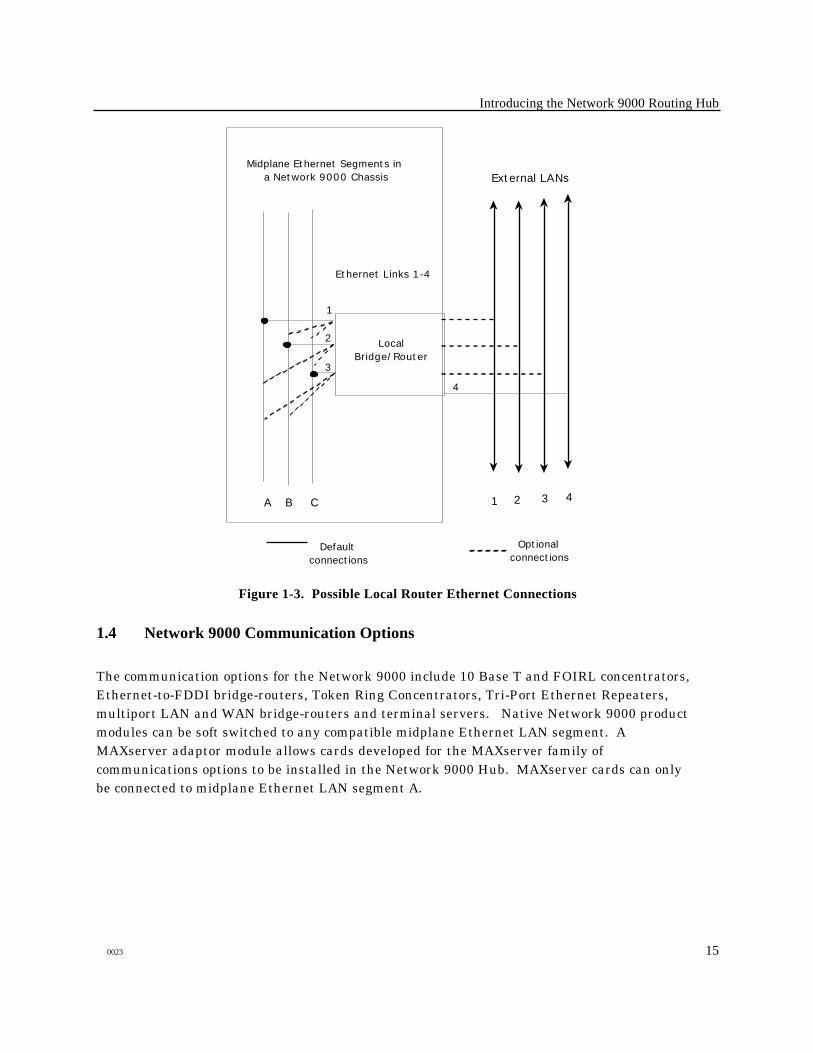
Soft switching is a feature that enables a network manager to configure via software whichLANs and which connectors a product module will use. For example, a four port local routerhas 4 AUI connectors on the I/O module and three midplane Ethernet LAN segments availablefor connection. Ethernet ports on the local router can be connected to the available connectorsor midplane LAN segments with a user command. Figure 1-3 depicts the possible connections.The user command can be executed via SNMP, or through the processor module's console port,or by connecting to the console from the network via Telnet or the DEC RCP protocol, or throughthe local management bus as previously described.
14 0023
Introducing the Network 9000 Routing Hub
CBA
Midplane Ethernet Segments in a Network 9000 Chassis External LANs
1 2 3
LocalBridge/Router
1
2
3
4
4
Ethernet Links 1-4
Default connections
Optional connections
Figure 1-3. Possible Local Router Ethernet Connections
1.4 Network 9000 Communication Options
The communication options for the Network 9000 include 10 Base T and FOIRL concentrators,Ethernet-to-FDDI bridge-routers, Token Ring Concentrators, Tri-Port Ethernet Repeaters,multiport LAN and WAN bridge-routers and terminal servers. Native Network 9000 productmodules can be soft switched to any compatible midplane Ethernet LAN segment. AMAXserver adaptor module allows cards developed for the MAXserver family ofcommunications options to be installed in the Network 9000 Hub. MAXserver cards can onlybe connected to midplane Ethernet LAN segment A.
0023 15
Introducing the Network 9000 Routing Hub
1.4.1 10Base-T/10Base-FL (FOIRL) Fiber Concentrators
The 10Base-T concentrators come in three models. The model 201 has 24 ports on two 50 pinTelco connectors, a management port and an AUI uplink. The model 202 is similar to themodel 201, but with the addition of an FOIRL fiber uplink. The model 203 has 20 ports usingRJ-45 connectors and a management port. The 10Base-FL concentrator has 12 fiber ports andis FOIRL compliant.
Each of these concentrators consists of an I/O module, which can optionally be used inconjunction with the Management Processor 210. The concentrator can connect to any of thethree midplane Ethernet LAN segments and also connects to the LMB. The concentrator doesnot require a software load image or operational parameters. Its operating software andcharacteristics are permanently stored on the I/O module. The concentrator determines whichmidplane Ethernet LAN segment it will connect to by reading initialization parameters locatedin the control storage. (You can configure which Ethernet LAN segment a concentrator will beconnected to from a Management Card or another product module in the Hub.) Theconcentrator provides status and control information which can be obtained by other productmodules in the Hub.
1.4.2 Enhanced Management Card
The Management Processor 210 provides an IEEE 802.1k compliant SNMP agent for theconcentrator. With additional memory (user upgradable SIMMs) it can also provide acommand line interface using the management port on a concentrator I/O module, or througha remote console mechanism (DEC RCP, Telnet, etc). When the model 210 is installed in theprocessor module slot it will continuously read status information from the I/O module in thesame slot (a concentrator) and process this information for retrieval via SNMP or the userinterface. Further, the model 210 can be directed to control and acquire status informationfrom a concentrator in another slot. The model 210 loads a software image and operationalparameters as described in the System Features section. If a memory card is installed it canload the software image and operational parameters from the memory card. It can also loadand store parameters for other products in the Network 9000 Hub.
16 0023
Introducing the Network 9000 Routing Hub
1.4.3 Internetworking
Internetworking in the Network 9000 is provided by the 410 and 460 bridge-router cards.Xyplex internetworking features include:
- Routing via IP-OSPF, IP-EGP, IP-RIP, IPX, DECnet IV, Appletalk (1992)- Concurrent bridging- Filtering on source, destination, protocol field and data patterns- Fully Distributed Redundant Bridging- PPP and Frame Relay WAN support
The model 410 is a four port local bridge router. The I/O module for the local bridge router hasfour AUI connectors. The four ports on the model 410 can be connected to any of the four AUIconnectors, or to the three midplane Ethernet LAN segments. For example, one couldconfigure the model 410 to connect to the three midplane Ethernet LAN segments and still haveone port available for connection to an external Ethernet LAN via an AUI connector.
The model 460 is a four port remote bridge-router with one Ethernet connection. The Ethernetconnection can be soft switched to one of the midplane Ethernet LAN segments or to an externalEthernet LAN via an AUI connector. The I/O module has four V.35 connectors.
MAXserver LAN and WAN bridge-routers are also available for the Network 9000 using theMAXserver adaptor module.
1.4.4 Terminal Server
The model 720 is the terminal server processor module for the Network 9000. Xyplex terminalserver features include:
- Licensed LAT- Telnet and Rlogin- TN3270- DECserver and Unix style commands- Accounting- Scripting- Multisessions support- SLIP- Kerberos authentication- Dialback modem security- Password security- SNMP, TSM and remote console via Telnet and RCP management- Xremote- Port to port connections with rotary support
0023 17
Introducing the Network 9000 Routing Hub
The model 720 is a high performance terminal server. It can be ordered with three types of I/Omodules: the 721, 724, and 723. The 721 I/O module supports 16 ports on two 50 pin Telcoconnectors. The 724 I/O module supports 24 ports on two 50 pin Telco connectors. Each portuses 6 wires per port to supply Xmt, Rcv, Gnd, DTR/RTS, DCD/CTS, and Ring signals. Whileeach port can operate at speeds up to 115.2 kbps, it is recommended that you be careful to useshort line lengths when operating at speeds greater than 64 kbps, due to "cross talk"considerations.
The model 723 I/O module has 20 ports with RJ-45 connectors. Each port uses 8 wires per port tosupply Xmt, XmtGnd, Rcv, RcvGnd, DTR, DCD, CTS/Ring and RTS. The RJ-45 ports arecapable of speeds up to 115.2 kbps.
1.4.5 MAXserver Adaptor I/O Module
The MAXserver adaptor I/O module allows the MAXserver family of communications optionsto be used in the Network 9000 Hub. It maps the MAXserver LANbus™ Ethernet channel andother necessary signals to the Network 9000 multimedia midplane. With this adaptor mostMAXserver family options (excluding the MAXman card) can use midplane Ethernet LANsegment A in the Network 9000 hub. The adaptor module provides a location in which to plug inthe MAXserver I/O connector card. Network 9000 Type 1 products also use the Adaptor I/Omodule, unless they are installed in slot 1. In this case, the AC power input module provides theAdaptor I/O function (refer to section 1.2.4).
18 0023
Chapter 2
Installing the Network 9000 Chassis
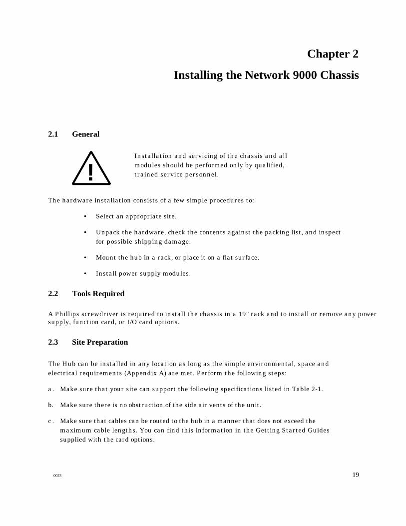
2.1 General
!Installation and servicing of the chassis and allmodules should be performed only by qualified,trained service personnel.
The hardware installation consists of a few simple procedures to:
• Select an appropriate site.
• Unpack the hardware, check the contents against the packing list, and inspectfor possible shipping damage.
• Mount the hub in a rack, or place it on a flat surface.
• Install power supply modules.
2.2 Tools Required
A Phillips screwdriver is required to install the chassis in a 19" rack and to install or remove any powersupply, function card, or I/O card options.
2.3 Site Preparation
The Hub can be installed in any location as long as the simple environmental, space andelectrical requirements (Appendix A) are met. Perform the following steps:
a . Make sure that your site can support the following specifications listed in Table 2-1.
b. Make sure there is no obstruction of the side air vents of the unit.
c . Make sure that cables can be routed to the hub in a manner that does not exceed themaximum cable lengths. You can find this information in the Getting Started Guidessupplied with the card options.
0023 19
Installing the Network 9000 Chassis
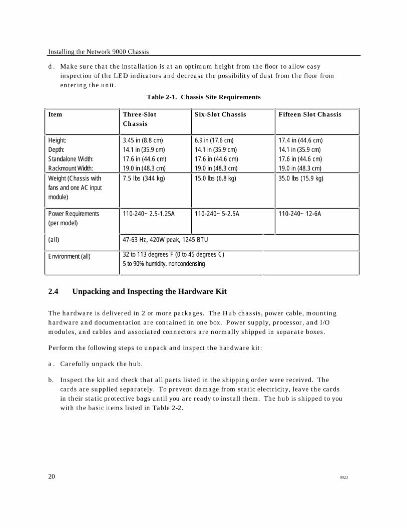
d . Make sure that the installation is at an optimum height from the floor to allow easyinspection of the LED indicators and decrease the possibility of dust from the floor fromentering the unit.
Table 2-1. Chassis Site Requirements
Item Three-SlotChassis
Six-Slot Chassis Fifteen Slot Chassis
Height:
Depth:
Standalone Width:
Rackmount Width:
3.45 in (8.8 cm)
14.1 in (35.9 cm)
17.6 in (44.6 cm)
19.0 in (48.3 cm)
6.9 in (17.6 cm)
14.1 in (35.9 cm)
17.6 in (44.6 cm)
19.0 in (48.3 cm)
17.4 in (44.6 cm)
14.1 in (35.9 cm)
17.6 in (44.6 cm)
19.0 in (48.3 cm)
Weight (Chassis with
fans and one AC input
module)
7.5 lbs (344 kg) 15.0 lbs (6.8 kg) 35.0 lbs (15.9 kg)
Power Requirements
(per model)
110-240~ 2.5-1.25A 110-240~ 5-2.5A 110-240~ 12-6A
(all) 47-63 Hz, 420W peak, 1245 BTU
Environment (all) 32 to 113 degrees F (0 to 45 degrees C)
5 to 90% humidity, noncondensing
2.4 Unpacking and Inspecting the Hardware Kit
The hardware is delivered in 2 or more packages. The Hub chassis, power cable, mountinghardware and documentation are contained in one box. Power supply, processor, and I/Omodules, and cables and associated connectors are normally shipped in separate boxes.
Perform the following steps to unpack and inspect the hardware kit:
a . Carefully unpack the hub.
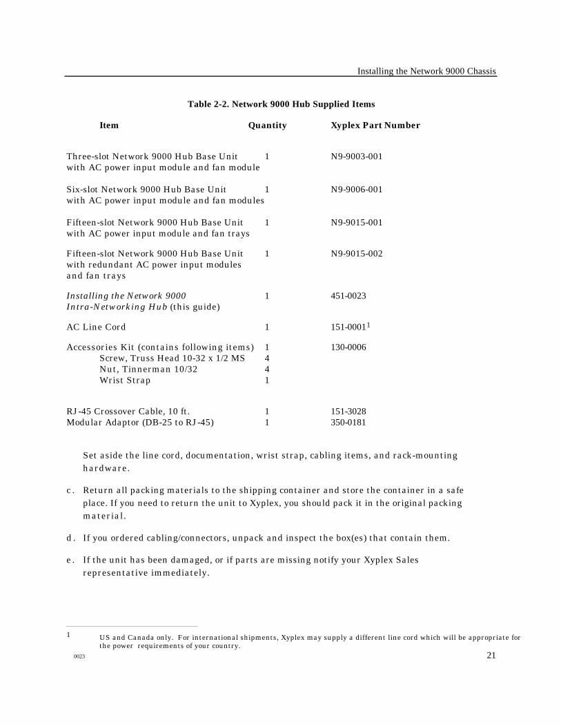
b. Inspect the kit and check that all parts listed in the shipping order were received. Thecards are supplied separately. To prevent damage from static electricity, leave the cardsin their static protective bags until you are ready to install them. The hub is shipped to youwith the basic items listed in Table 2-2.
20 0023
Installing the Network 9000 Chassis
Table 2-2. Network 9000 Hub Supplied Items
Item Quantity Xyplex Part Number
Three-slot Network 9000 Hub Base Unit 1 N9-9003-001with AC power input module and fan module
Six-slot Network 9000 Hub Base Unit 1 N9-9006-001with AC power input module and fan modules
Fifteen-slot Network 9000 Hub Base Unit 1 N9-9015-001with AC power input module and fan trays
Fifteen-slot Network 9000 Hub Base Unit 1 N9-9015-002with redundant AC power input modulesand fan trays
Installing the Network 9000 1 451-0023Intra-Networking Hub (this guide)
AC Line Cord 1 151-00011
Accessories Kit (contains following items) 1 130-0006Screw, Truss Head 10-32 x 1/2 MS 4Nut, Tinnerman 10/32 4Wrist Strap 1
RJ-45 Crossover Cable, 10 ft. 1 151-3028Modular Adaptor (DB-25 to RJ-45) 1 350-0181
Set aside the line cord, documentation, wrist strap, cabling items, and rack-mountinghardware.
c . Return all packing materials to the shipping container and store the container in a safeplace. If you need to return the unit to Xyplex, you should pack it in the original packingmaterial.
d . If you ordered cabling/connectors, unpack and inspect the box(es) that contain them.
e . If the unit has been damaged, or if parts are missing notify your Xyplex Salesrepresentative immediately.
1 US and Canada only. For international shipments, Xyplex may supply a different line cord which will be appropriate forthe power requirements of your country.
0023 21
Installing the Network 9000 Chassis
2.5 Mounting
2.5.1 General
The chassis can be installed in either a 19-inch rack or can stand alone on a flat surface aslong as adequate ventilation is provided. The unit is cooled by pulling air from the side of thechassis. The air is expelled through the side fan ducts.
2.5.2 Rack Mount Installation
A height of 6.9 inches (17.6 cm) is required for the six-slot chassis. A height of 17.4 inches (44.6cm) is required for the fifteen-slot chassis. Perform the following steps to install the unit in a19-inch rack:
a . Locate a mounting position.
☞ If you need to, you can remove the "feet" at the bottom of the chassis, byusing a flat-head screwdriver to pry out the plastic post in the center.
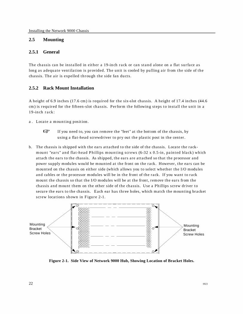
b. The chassis is shipped with the ears attached to the side of the chassis. Locate the rack-mount "ears" and flat-head Phillips mounting screws (6-32 x 0.5-in, painted black) whichattach the ears to the chassis. As shipped, the ears are attached so that the processor andpower supply modules would be mounted at the front on the rack. However, the ears can bemounted on the chassis on either side (which allows you to select whether the I/O modulesand cables or the processor modules will be in the front of the rack. If you want to rackmount the chassis so that the I/O modules will be at the front, remove the ears from thechassis and mount them on the other side of the chassis. Use a Phillips screw driver tosecure the ears to the chassis. Each ear has three holes, which match the mounting bracketscrew locations shown in Figure 2-1.
Mounting BracketScrew Holes
Mounting BracketScrew Holes
Figure 2-1. Side View of Network 9000 Hub, Showing Location of Bracket Holes.
22 0023
Installing the Network 9000 Chassis
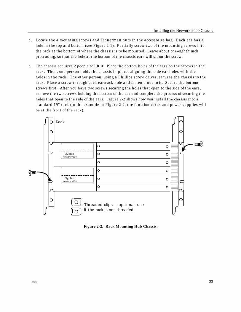
c . Locate the 4 mounting screws and Tinnerman nuts in the accessories bag. Each ear has ahole in the top and bottom (see Figure 2-1). Partially screw two of the mounting screws intothe rack at the bottom of where the chassis is to be mounted. Leave about one-eighth inchprotruding, so that the hole at the bottom of the chassis ears will sit on the screw.
d . The chassis requires 2 people to lift it. Place the bottom holes of the ears on the screws in therack. Then, one person holds the chassis in place, aligning the side ear holes with theholes in the rack. The other person, using a Phillips screw driver, secures the chassis to therack. Place a screw through each ear/rack hole and fasten a nut to it. Secure the bottomscrews first. After you have two screws securing the holes that open to the side of the ears,remove the two screws holding the bottom of the ear and complete the process of securing theholes that open to the side of the ears. Figure 2-2 shows how you install the chassis into astandard 19" rack (in the example in Figure 2-2, the function cards and power supplies willbe at the front of the rack).
Rack
Threaded clips -- optional; use if the rack is not threaded
XyplexNetwork 9000
XyplexNetwork 9000
Figure 2-2. Rack Mounting Hub Chassis.
0023 23
Installing the Network 9000 Chassis
2.5.3 Stand-Alone Installation
The hub can be mounted in any location as long as the site requirements (paragraph 2.3) aremet. A location should be selected that does not require each cable's maximum bend radius tobe exceeded. If you wish, you can remove the mounting ears and store them for later use.
2.6 Additional Installation Activities
After you have completed the chassis installation, you must install power supplies, functioncards, and I/O cards with their associated cabling. Chapter 3 describes the procedures forinstalling power supplies. Chapter 4 describes the general procedure for installing functioncards and I/O cards into the chassis. You should also refer to the Getting Started Guidesupplied with each function card for any installation notes that are specific to the card, as wellas cabling information.
24 0023
Chapter 3
Power Supplies, Fans, and AC Input Modules
!Installation and servicing of the chassis and all modulesshould be performed only by qualified, trained servicepersonnel.
High voltages are present inside the Network 9000Chassis. Observe the following safety precautions wheninstalling or removing any modules:
• Do not insert metallic objects (such as a screwdriver,etc) inside the Network 9000 chassis, while power is on.If you must straighten out a bent pin on the midplane,you MUST first turn off power to the chassis.
• All midplane servicing must be done only by qualifiedservice personnel.
3.1 General
The AC power input module, power supply modules, and fan tray modules are removable.Depending on your Network 9000 hub configuration, the power supplies may be "hot swapped"without bringing the unit down. This chapter describes the procedures used to install andremove these options, and provides a quick reference to the controls and indicators found onthe ac input and power supply modules.
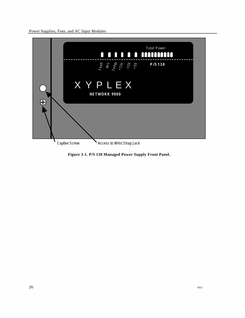
3.2 Power Supply Modules
Figure 3-1 shows the front panel of the P/S 130 Managed Power Supply. Table 3-1 lists the LEDindicators and controls of the P/S 130 Managed Power Supply.
0023 25
Power Supplies, Fans, and AC Input Modules
XYPLEXN E T W O R K 9 0 0 0
P / S 1 3 0
Tota l Power
Access to Wrist Strap Jack
-12V
+5
V
+12V
Fau
l t
N+1
Tem
p
Captive Screw
Figure 3-1. P/S 130 Managed Power Supply Front Panel.
26 0023

Power Supplies, Fans, and AC Input Modules
Table 3-1. P/S 130 LED Indicators.
Item Purpose
Fault LED ON - indicates that an internal power supply fault has occurred. You should examine the otherLEDs for specific details of the fault condition.
OFF - indicates that the power supply is functioning properly.
Flashing - indicates that the power supply has been inhibited. All other LEDs will be off.
N+1
LED
ON - indicates that if one power supply in the hub fails, is removed, or is inhibited via the On/Offswitch the remaining power supplies will have sufficient capacity to provide power and insureuninterrupted operation (i.e., power supplies are operating redundantly).
OFF - indicates that if one power supply in the hub fails, is removed, or is inhibited via the On/Offswitch the remaining power supplies will not have sufficient capacity to provide power and insureuninterrupted operation (i.e., power supplies are not operating redundantly).
Temp
LED
ON - indicates that the temperature in the power supply is within normal operating limits (less than55° C).
OFF - indicates that the temperature in the power supply is outside normal operating limits(greater than 55° C).
+12V LED ON - indicates that the +12 Vdc supply is functioning within normal operating limits.
OFF - indicates that the +12 Vdc supply is not functioning within normal operating limits.
-12V LED ON - indicates that the -12 Vdc supply is functioning within normal operating limits.
OFF - indicates that the -12 Vdc supply is not functioning within normal operating limits.
+5V
LED
ON - indicates that the +5 Vdc supply is functioning within normal operating limits.
OFF - indicates that the +5 Vdc supply is not functioning within normal operating limits.
Total
Power
LEDs
LEDs form a bar graph indicating how much power is being provided by the power supplymodule. Each LED segment indicates 15W of output power. When all LEDs are lit, the hub isdrawing on the full capacity of the power supply. Fewer LEDs lit indicate that the power supplycan handle additional load.
0023 27

Power Supplies, Fans, and AC Input Modules
3.2.1 Installing and Removing Power Supply Modules
The Network 9000 architecture permits you to add, change, and remove power supply moduleswhile the unit is powered on. Depending upon the configuration of your hub power supplies, thiscan sometimes be done without disrupting other devices in the hub.
The installation and removal of power supply modules is uncomplicated. Each unused powersupply slot is covered by a blank panel. To install a new power supply module, remove the blankpanel and insert the power supply module. Secure the module with the Phillips head captive screw.
Installing Power Supplies
Depending on the Hub model, power supply slots are numbered 1 through 2, or 1 through 5,beginning from the bottom.
Perform the following steps to install a power supply:
a . Loosen the 1 screw securing the front blank panel of the selected power supply slot. Removethe panel.
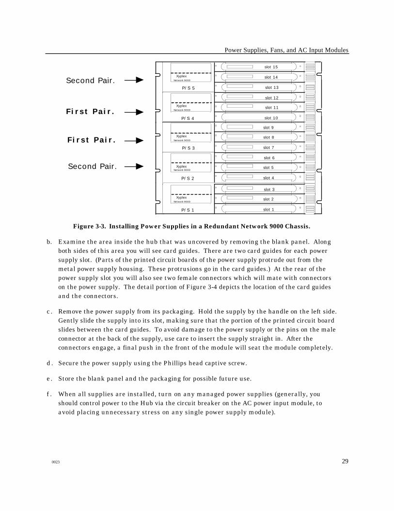
For a standard Network 9000 chassis, Xyplex recommends that you install P/S 130 modulesin the order shown in Figure 3-2 (slots P/S 2, P/S 3, P/S 4, P/S 1, and P/S 5). For aredundant Network 9000 chassis, Xyplex recommends that you install P/S 130 modules inpairs in the order shown in Figure 3-3 (slots P/S 2 and P/S 3, then P/S 4 and P/S 1).
XyplexNetwork 9000
XyplexNetwork 9000
slot 10
slot 11
slot 12
slot 13
slot 14
slot 15
P/S 4
P/S 5
XyplexNetwork 9000
XyplexNetwork 9000
slot 4
slot 5
slot 6
slot 7
slot 8
slot 9
P/S 2
P/S 3
XyplexNetwork 9000
slot 1
slot 2
slot 3
P/S 1
Install first.
Install second.
Install third.
Install fourth.
Install fifth.
Figure 3-2. Installing Power Supplies in a Standard Network 9000 Chassis.
28 0023
Power Supplies, Fans, and AC Input Modules
XyplexNetwork 9000
XyplexNetwork 9000
slot 10
slot 11
slot 12
slot 13
slot 14
slot 15
P/S 4
P/S 5
XyplexNetwork 9000
XyplexNetwork 9000
slot 4
slot 5
slot 6
slot 7
slot 8
slot 9
P/S 2
P/S 3
XyplexNetwork 9000
slot 1
slot 2
slot 3
P/S 1
First Pair.
First Pair.
Second Pair.
Second Pair.
Figure 3-3. Installing Power Supplies in a Redundant Network 9000 Chassis.
b. Examine the area inside the hub that was uncovered by removing the blank panel. Alongboth sides of this area you will see card guides. There are two card guides for each powersupply slot. (Parts of the printed circuit boards of the power supply protrude out from themetal power supply housing. These protrusions go in the card guides.) At the rear of thepower supply slot you will also see two female connectors which will mate with connectorson the power supply. The detail portion of Figure 3-4 depicts the location of the card guidesand the connectors.
c . Remove the power supply from its packaging. Hold the supply by the handle on the left side.Gently slide the supply into its slot, making sure that the portion of the printed circuit boardslides between the card guides. To avoid damage to the power supply or the pins on the maleconnector at the back of the supply, use care to insert the supply straight in. After theconnectors engage, a final push in the front of the module will seat the module completely.
d . Secure the power supply using the Phillips head captive screw.
e . Store the blank panel and the packaging for possible future use.
f . When all supplies are installed, turn on any managed power supplies (generally, youshould control power to the Hub via the circuit breaker on the AC power input module, toavoid placing unnecessary stress on any single power supply module).
0023 29

Power Supplies, Fans, and AC Input Modules
Removing Power Supplies
Reverse the power supply installation procedure to remove any power supply. Perform thefollowing steps to remove any power supply:
a . Loosen the captive screw securing the power supply to the chassis.
b. Grasp the handle on the left side of the supply and pull straight back. The power supply willslide out.
c . If the supply is to be replaced with another, install the new supply and secure it. If the supplywill not be replaced with another, cover the empty slot with a blank panel. Secure the panelto the chassis using the screws supplied with the panel.
☞ It is essential that you cover an empty slot with a blank panel to ensure proper
chassis cooling and safety.
30 0023
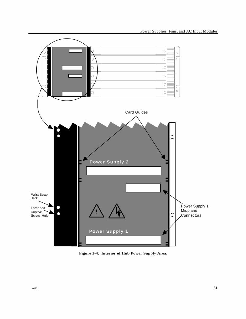
Power Supplies, Fans, and AC Input Modules
Power Supply 1
Power Supply 2
Card Guides
Threaded CaptiveScrew Hole
Wrist Strap Jack
Power Supply 1 Midplane Connectors
!
Figure 3-4. Interior of Hub Power Supply Area.
0023 31
Power Supplies, Fans, and AC Input Modules
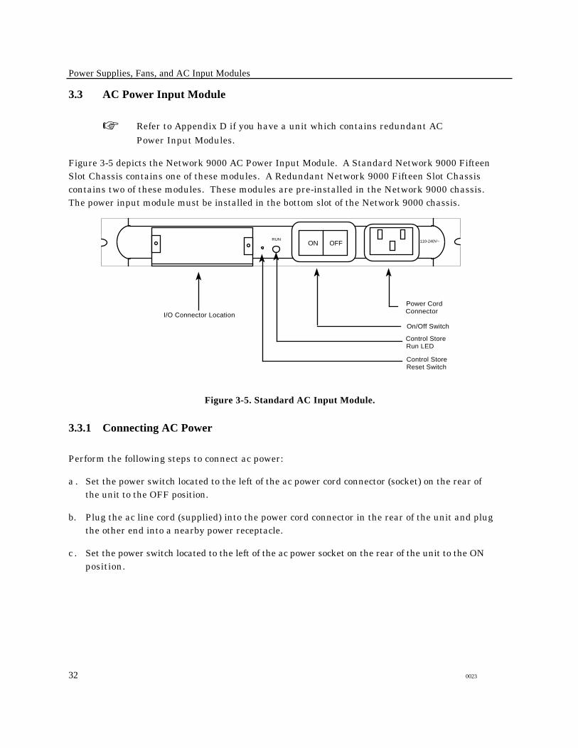
3.3 AC Power Input Module
☞ Refer to Appendix D if you have a unit which contains redundant ACPower Input Modules.
Figure 3-5 depicts the Network 9000 AC Power Input Module. A Standard Network 9000 FifteenSlot Chassis contains one of these modules. A Redundant Network 9000 Fifteen Slot Chassiscontains two of these modules. These modules are pre-installed in the Network 9000 chassis.The power input module must be installed in the bottom slot of the Network 9000 chassis.
RUNON OFF 110-240V~
Power Cord Connector
On/Off Switch
Control Store Run LED
Control Store Reset Switch
I/O Connector Location
Figure 3-5. Standard AC Input Module.
3.3.1 Connecting AC Power
Perform the following steps to connect ac power:
a . Set the power switch located to the left of the ac power cord connector (socket) on the rear ofthe unit to the OFF position.
b. Plug the ac line cord (supplied) into the power cord connector in the rear of the unit and plugthe other end into a nearby power receptacle.
c . Set the power switch located to the left of the ac power socket on the rear of the unit to the ONposition.
32 0023
Power Supplies, Fans, and AC Input Modules
3.3.2 Installing and Removing the AC Power Input Module
A Standard Network 9000 Fifteen Slot Chassis contains one of these modules. A RedundantNetwork 9000 Fifteen Slot Chassis contains two of these modules. One module is always locatedin the bottom I/O card slot of the hub. In a Redundant Network 9000 Fifteen Slot Chassis, thesecond module is installed in slot 10. You will only need to remove an AC Power Input Module ifit fails or you wish to swap or repair the chassis itself. (If you install the AC Power Input Module,and the same functional units into a new chassis, no reconfiguration of the functional units willbe needed. Contact Xyplex Customer Support in the event that the AC Power Input Module itselfneeds to be replaced - it may be possible to lessen the requirements for reconfiguring your hub.)If a failure occurs, use the following procedures to remove a failed module and replace it withanother one.
Removing the AC Power Input Module
Perform the following steps to remove the ac power input module:
a . Turn the power switch on the AC Power Input Module to the Off position.
b. Disconnect the power cord from the ac power input module.
c . If there is an I/O connector installed on the AC Power Input Module, remove the cables fromthe I/O connector. Loosen the 2 screws securing any I/O connector from the power inputmodule. Remove the I/O connector from the module.d. Loosen the 2 screws securing thepower input module to the chassis.
e . Grasp the ejector handles on the edges of the module and swing them out away from themodule. The module will then pop free allowing you to slide it straight out from the chassis.
Installing a New AC Power Input Module
Perform the following steps to install a replacement AC power input module:
a . Remove the replacement AC power input module from its packaging.
b. Examine the area inside the hub slot that was uncovered by removing the ac power inputmodule. Along both sides of the slot you will see two card guides, which consist of twoprotrusions formed in the metal separated by about one-eighth inch. Gently slide themodule into the slot between the card guides. To avoid damage to the AC input powermodule or the pins on the male connectors on the midplane at the back of the slot, use care toinsert the module straight in.
c . Secure the power module using the two captive screws.
d . If there was an I/O connector installed in the previously removed ac power input module,re-install the I/O connector. Remove the blank plate from the module and secure the I/Oconnector with its screws.
e . Ensure that the power switch is in the Off position. Plug the ac line cord (supplied) into theconnector in the rear of the unit and plug the other end into a nearby power receptacle.
f . Set the power switch located to the left of the ac power socket on the rear of the unit to ON.
0023 33
Power Supplies, Fans, and AC Input Modules
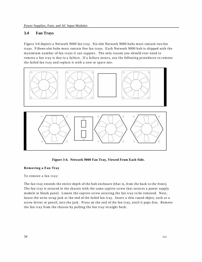
3.4 Fan Trays
Figure 3-6 depicts a Network 9000 fan tray. Six-slot Network 9000 hubs must contain two fantrays. Fifteen-slot hubs must contain five fan trays. Each Network 9000 hub is shipped with themaximium number of fan trays it can support. The only reason you should ever need toremove a fan tray is due to a failure. If a failure occurs, use the following procedures to removethe failed fan tray and replace it with a new or spare one.
Figure 3-6. Network 9000 Fan Tray, Viewed From Each Side.
Removing a Fan Tray
To remove a fan tray:
The fan tray extends the entire depth of the hub enclosure (that is, from the back to the front).The fan tray is secured in the chassis with the same captive screw that secures a power supplymodule or blank panel. Loosen the captive screw securing the fan tray to be removed. Next,locate the wrist strap jack at the end of the failed fan tray. Insert a thin round object, such as ascrew driver or pencil, into the jack. Press on the end of the fan tray, until it pops free. Removethe fan tray from the chassis by pulling the fan tray straight back.
34 0023
Power Supplies, Fans, and AC Input Modules
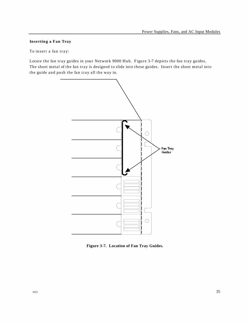
Inserting a Fan Tray
To insert a fan tray:
Locate the fan tray guides in your Network 9000 Hub. Figure 3-7 depicts the fan tray guides.The sheet metal of the fan tray is designed to slide into these guides. Insert the sheet metal intothe guide and push the fan tray all the way in.
Figure 3-7. Location of Fan Tray Guides.
0023 35
Chapter 4
Installing and Removing Processorand I/O Modules
!Installation and servicing of the chassis and allmodules should be performed only by qualified,trained service personnel.
4.1 General
The Network 9000 architecture permits you to add, change, and remove modules while the hubis powered on, without disrupting other devices. This chapter describes the installation andremoval of modules.
CAUTIONALWAYS WEAR AN ANTI-STATIC BRACELET BEFORE HANDLING ANYNetwork 9000 MODULES. Each Network 9000 chassis comes with an anti-staticbracelet that attaches to a jack next to the power supply (see Figure 4-1).
The installation and removal of modules is uncomplicated. Each unused slot is covered byblank panels in both the front and rear of the unit. To install a new module, the front and rearblank panels are removed, and the processor module and the associated I/O module are theninserted. The appropriate cables are then connected.
4.2 Installing and Removing Modules
Depending on the model of Network 9000 hub you have, slots are numbered designated as 1-15or from 1-6 beginning from the bottom. A Network 9000 module can be placed in any availableslot, except slot 1. (Slot 1 contains the ac power input module, but can be used with a single-slotmodule from the MAXserver family of communication options.) Do not remove the modulefrom the static-protection bag yet!
Perform the following steps to install a module:
a . Attach a grounding wrist bracelet to one wrist and plug the grounding strap into the jacklocated to the left of the power supply front panel.
b. Loosen the 2 screws securing the blank panel of the selected slot. Remove the blank panel.
0023 36
Installing and Removing Processor and I/O Modules
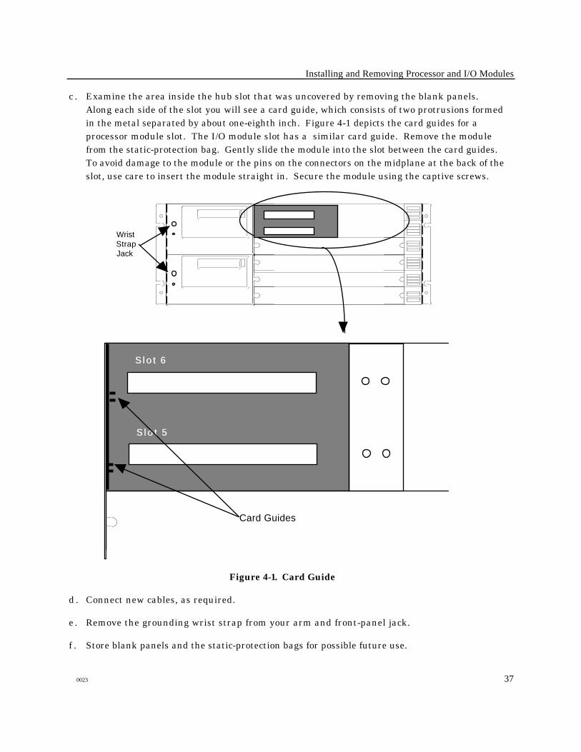
c . Examine the area inside the hub slot that was uncovered by removing the blank panels.Along each side of the slot you will see a card guide, which consists of two protrusions formedin the metal separated by about one-eighth inch. Figure 4-1 depicts the card guides for aprocessor module slot. The I/O module slot has a similar card guide. Remove the modulefrom the static-protection bag. Gently slide the module into the slot between the card guides.To avoid damage to the module or the pins on the connectors on the midplane at the back of theslot, use care to insert the module straight in. Secure the module using the captive screws.
Slot 5
Slot 6
Card Guides
Wrist Strap Jack
Figure 4-1. Card Guide
d . Connect new cables, as required.
e . Remove the grounding wrist strap from your arm and front-panel jack.
f . Store blank panels and the static-protection bags for possible future use.
0023 37
Installing and Removing Processor and I/O Modules
Removing Modules
Reverse the module installation procedure to remove any module. The cabling and associatedI/O module in the rear of the unit will only have to be disconnected if the slot is no longer to beused with the same type of I/O module. Leave the I/O module and cabling connected to this slotif you are swapping the processor module with a new processor module of the same type, or ifyou are reseating the module if a self-test failure occurred.
Perform the following steps to remove any module:
a . Locate the static-protective bag for the module.
b. Attach a grounding wrist bracelet to one wrist and plug the grounding strap into the jacklocated on the power supply front panel.
CAUTIONALWAYS WEAR AN ANTI-STATIC BRACELET BEFORE HANDLING ANYNetwork 9000 MODULES. Each Network 9000 hub comes with an anti-staticbracelet that attaches to the jack on the power supply front panel (see Figure 4-1).
c . Using a bent paper-clip "tool" press the reset switch on the processor module once to placethe module into reset mode. (You should do this even if you are removing an I/O module.In this case, place the processor module, that is in the same slot as the I/O module to beremoved, into reset mode.)
☞ Do not remove a running processor module which contains a flash memory card,without first placing the module into reset mode, or you can corrupt the memory card.
d . Loosen the 2 screws securing the module to the chassis.
e . Grasp the ejector handles on the edges of the module and swing them out away from themodule. The module will then pop free allowing you to slide it straight out from thechassis. Place the module in the protective bag.
f . If the processor module is to be replaced with another module of the same type, install thenew module and secure it. Normally, the I/O module and cabling can be left connectedwhen swapping only a processor module. If the new processor module is a different type ofmodule than the one being replaced, you will usually need to remove the I/O module andreplace it with an I/O module that is appropriate to the new processor module. If you areonly changing the I/O module, install the new I/O cable module and secure it using the 2captive screws. Then, connect the appropriate cabling for this interface. Perform step "f"if the slot will not be used immediately.
g . Cover the empty slot with a blank panel. Secure the panel to the hub using the captive screwssupplied with the panel.
☞ It is essential that you cover an empty slot with a blank panel to ensure properchassis cooling.
38 0023
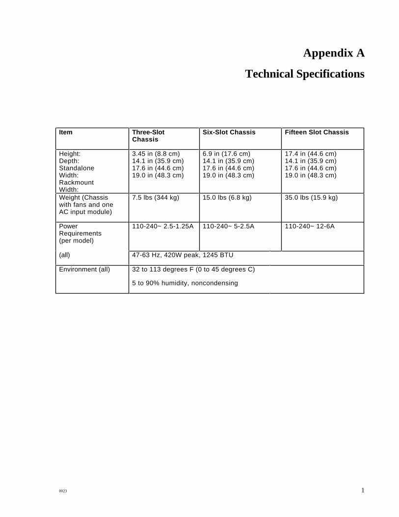
Appendix A
Technical Specifications
Item Three-SlotChassis
Six-Slot Chassis Fifteen Slot Chassis
Height:Depth:StandaloneWidth:RackmountWidth:
3.45 in (8.8 cm)14.1 in (35.9 cm)17.6 in (44.6 cm)19.0 in (48.3 cm)
6.9 in (17.6 cm)14.1 in (35.9 cm)17.6 in (44.6 cm)19.0 in (48.3 cm)
17.4 in (44.6 cm)14.1 in (35.9 cm)17.6 in (44.6 cm)19.0 in (48.3 cm)
Weight (Chassiswith fans and oneAC input module)
7.5 lbs (344 kg) 15.0 lbs (6.8 kg) 35.0 lbs (15.9 kg)
PowerRequirements(per model)
110-240~ 2.5-1.25A 110-240~ 5-2.5A 110-240~ 12-6A
(all) 47-63 Hz, 420W peak, 1245 BTU
Environment (all) 32 to 113 degrees F (0 to 45 degrees C)
5 to 90% humidity, noncondensing
0023 1
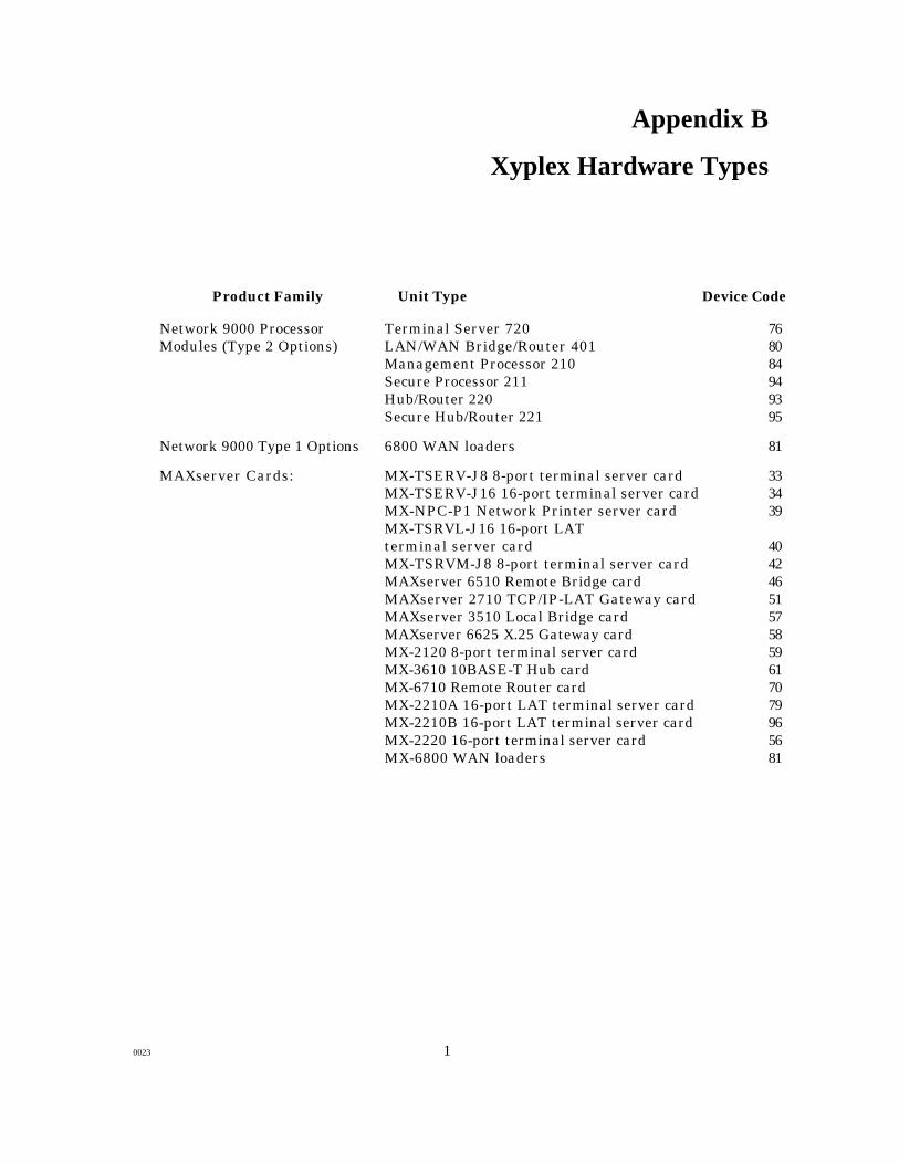
Appendix B
Xyplex Hardware Types
Product Family Unit Type Device Code
Network 9000 Processor Terminal Server 720 76Modules (Type 2 Options) LAN/WAN Bridge/Router 401 80
Management Processor 210 84Secure Processor 211 94Hub/Router 220 93Secure Hub/Router 221 95
Network 9000 Type 1 Options 6800 WAN loaders 81
MAXserver Cards: MX-TSERV-J8 8-port terminal server card 33MX-TSERV-J16 16-port terminal server card 34MX-NPC-P1 Network Printer server card 39MX-TSRVL-J16 16-port LATterminal server card 40MX-TSRVM-J8 8-port terminal server card 42MAXserver 6510 Remote Bridge card 46MAXserver 2710 TCP/IP-LAT Gateway card 51MAXserver 3510 Local Bridge card 57MAXserver 6625 X.25 Gateway card 58MX-2120 8-port terminal server card 59MX-3610 10BASE-T Hub card 61MX-6710 Remote Router card 70MX-2210A 16-port LAT terminal server card 79MX-2210B 16-port LAT terminal server card 96MX-2220 16-port terminal server card 56MX-6800 WAN loaders 81
0023 1

Appendix C
Slot Ethernet Addresses
Each slot of a Network 9000 Chassis has a unique Ethernet address. When a device is installed ina given slot, it acquires the Ethernet address of that slot. There is a label on the AC Power InputModule which specifies the Ethernet address for the slot 1. This is the "base address" of thechassis. To determine the address for each slot, substitute the last digit of the slot 1 Ethernetaddress with the hexadecimal number shown in the following table:
Slot Number Hexadecimal Digit
1 12 23 34 45 56 67 78 89 910 A11 B12 C13 D14 E15 F
Example: Assume that the base Ethernet address for the chassis is 08-00-87-01-46-D1. For each
slot in that chassis, the Ethernet addresses would be:
Slot Number Hexadecimal Digit
1 08-00-87-01-46-D12 08-00-87-01-46-D23 08-00-87-01-46-D34 08-00-87-01-46-D45 08-00-87-01-46-D56 08-00-87-01-46-D67 08-00-87-01-46-D78 08-00-87-01-46-D89 08-00-87-01-46-D910 08-00-87-01-46-DA11 08-00-87-01-46-DB12 08-00-87-01-46-DC13 08-00-87-01-46-DD14 08-00-87-01-46-DE15 08-00-87-01-46-DF
0023 41
Appendix D
Network 9000 Redundant AC Power Input Modules
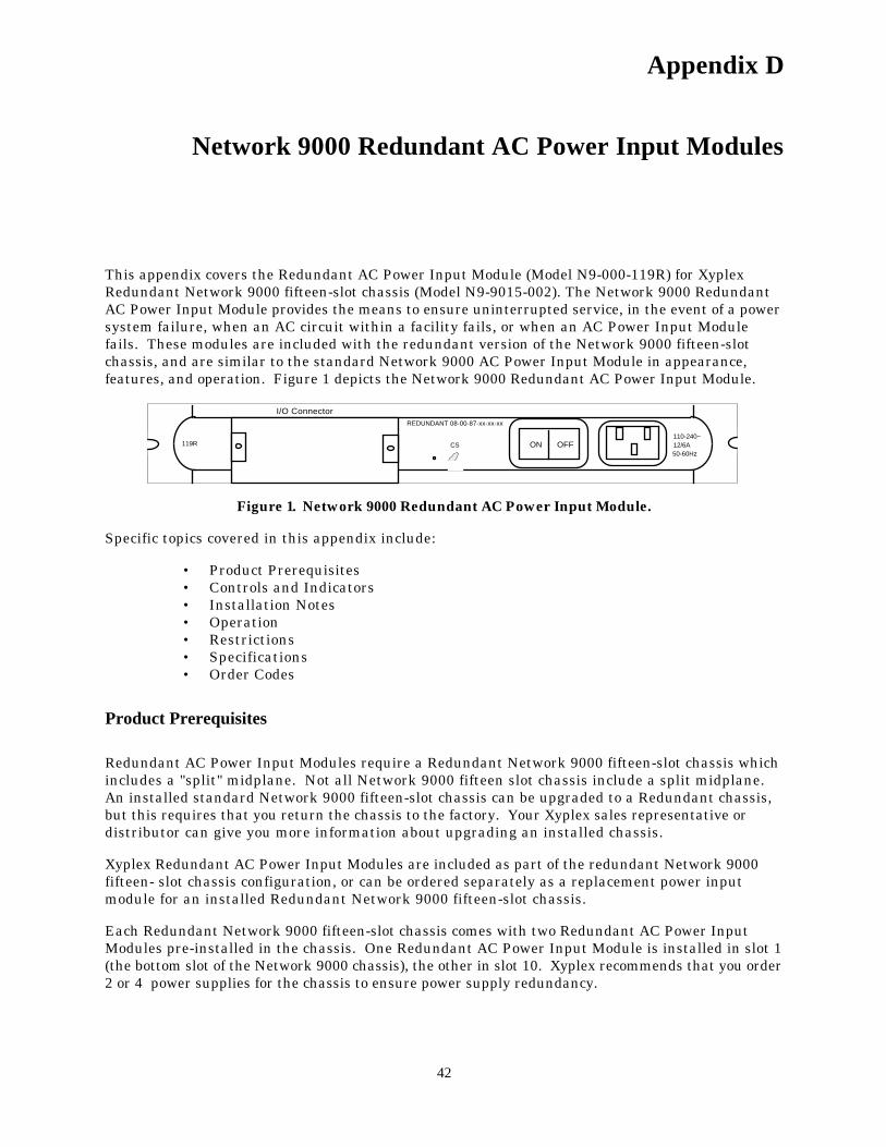
This appendix covers the Redundant AC Power Input Module (Model N9-000-119R) for XyplexRedundant Network 9000 fifteen-slot chassis (Model N9-9015-002). The Network 9000 RedundantAC Power Input Module provides the means to ensure uninterrupted service, in the event of a powersystem failure, when an AC circuit within a facility fails, or when an AC Power Input Modulefails. These modules are included with the redundant version of the Network 9000 fifteen-slotchassis, and are similar to the standard Network 9000 AC Power Input Module in appearance,features, and operation. Figure 1 depicts the Network 9000 Redundant AC Power Input Module.
110-240~12/6A50-60Hz
ON OFFCS119R
I/O ConnectorREDUNDANT 08-00-87-xx-xx-xx
Figure 1. Network 9000 Redundant AC Power Input Module.
Specific topics covered in this appendix include:
• Product Prerequisites• Controls and Indicators• Installation Notes• Operation• Restrictions• Specifications• Order Codes
Product Prerequisites
Redundant AC Power Input Modules require a Redundant Network 9000 fifteen-slot chassis whichincludes a "split" midplane. Not all Network 9000 fifteen slot chassis include a split midplane.An installed standard Network 9000 fifteen-slot chassis can be upgraded to a Redundant chassis,but this requires that you return the chassis to the factory. Your Xyplex sales representative ordistributor can give you more information about upgrading an installed chassis.
Xyplex Redundant AC Power Input Modules are included as part of the redundant Network 9000fifteen- slot chassis configuration, or can be ordered separately as a replacement power inputmodule for an installed Redundant Network 9000 fifteen-slot chassis.
Each Redundant Network 9000 fifteen-slot chassis comes with two Redundant AC Power InputModules pre-installed in the chassis. One Redundant AC Power Input Module is installed in slot 1(the bottom slot of the Network 9000 chassis), the other in slot 10. Xyplex recommends that you order2 or 4 power supplies for the chassis to ensure power supply redundancy.
42
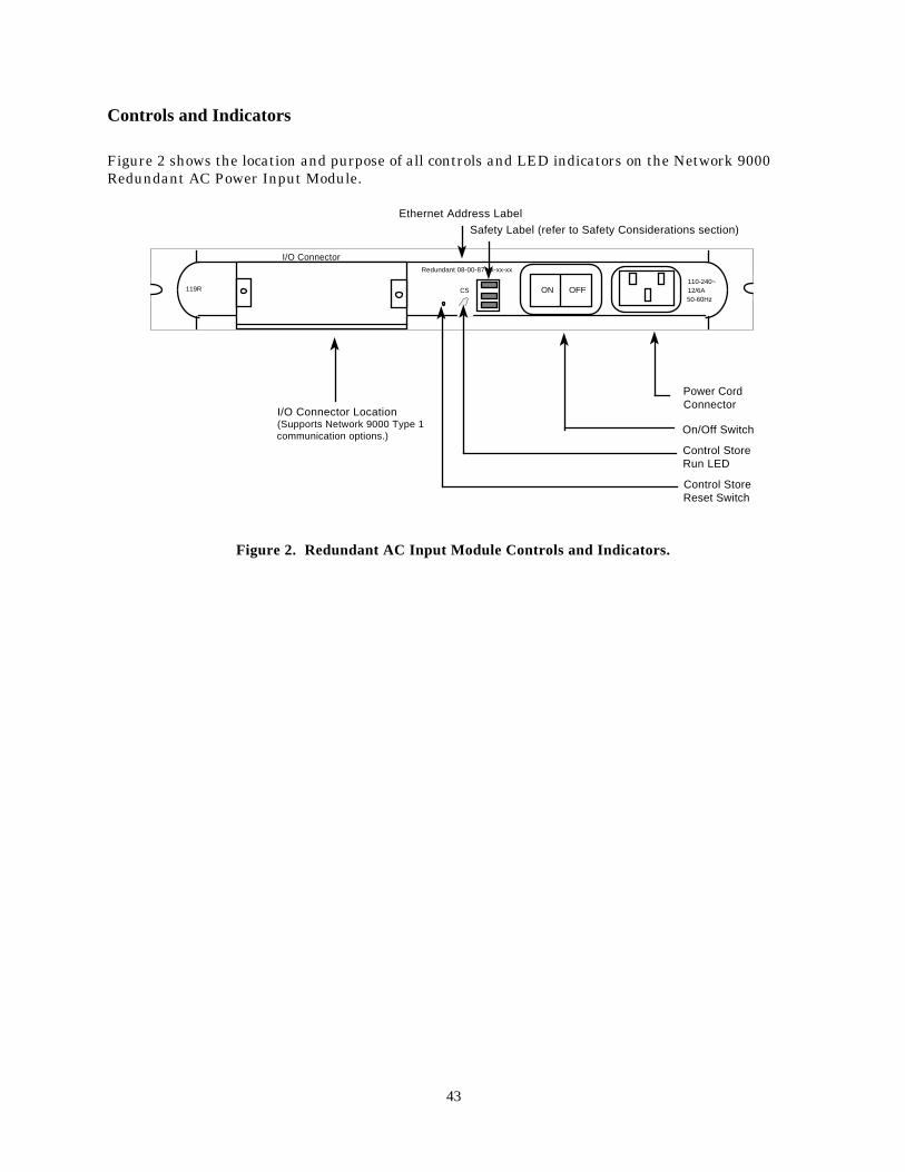
Controls and Indicators
Figure 2 shows the location and purpose of all controls and LED indicators on the Network 9000Redundant AC Power Input Module.
110-240~12/6A50-60Hz
ON OFFCS119R
I/O ConnectorRedundant 08-00-87-xx-xx-xx
Power Cord Connector
On/Off Switch
Control Store Run LED
Control Store Reset Switch
I/O Connector Location(Supports Network 9000 Type 1 communication options.)
Ethernet Address Label
Safety Label (refer to Safety Considerations section)
Figure 2. Redundant AC Input Module Controls and Indicators.
43

Installation Notes
The power input modules and power supply modules are removable. When configured as aredundant system, individual power input modules and power supply modules may be "hotswapped" without bringing the unit down. Generally, you install power supply modules andRedundant AC Power Input Modules using the standard installation and removal procedures,that are described in Chapter 3. This section describes some minor differences fromprocedures, that are due to the use of Redundant AC Power Input Modules.
Safety Considerations
!Installation and servicing of the chassis and all modulesshould be performed only by qualified, trained servicepersonnel.
Do not insert any item, such as a screwdriver (for example tostraighten out a bent pin, etc), into the inside of the chassiswhile power is on as damage to the equipment can occur.
Use caution when installing or removing modules. Do not remove any item from the Network9000 midplane. All modifications or upgrades to the midplane must be made at the factory.
A safety label is affixed to each Redundant AC Power Input Module (see Figure 2 for location).This label states:
CAUTION- THIS UNIT HAS MORE THAN ONE POWER SUPPLY CORD. DISCONNECT 2POWER SUPPLY CORDS BEFORE SERVICING TO AVOID ELECTRIC SHOCK.
ATTENTION- CET APPAREIL COMPORTE PLUS D'UN CORDON D'ALIMENTATION.AFIN DE PREVENIR LES CHOCS ELECTRIQUES, DEBRANCHER LES 2 CORDONS.D'ALIMENTATION AVANT DE FAIRE LE DEPANNGE.
ACHTUNG- DIESES GERAT BESITZT ZWEI NETZANSCHLUSSE VOR DEM BEGINN VONWARTUNGSARBEITEN TRENNEN SIE UNBEDINGT BEIDE ANSCHLUSSE VOM NETZ.
Power Supply Planning Considerations
With a Redundant Network 9000 chassis configuration, you can obtain redundancy for a systemdrawing a maximum of 300 W of power (two 150 W power supplies when using P/S 130 power supplymodules). When using the power supply worksheets, you must ensure that the communicationoptions that you install in the Network 9000 chassis can be adequately powered by a total of 300W.
44

Installing Power Supplies
When using a Redundant AC Power Input Module, each individual module shares some of theload during normal operation. The power input module in slot 1 provides AC power to the powersupplies in power supply slots 1, 2, and 3. The power input module in slot 10 provides AC power tothe power supplies in power supply slots 4 and 5. When one AC power source fails, or when onepower input module fails, the power supplies in the associated power supply slots will go into a faultcondition. The power supplies that are associated with the functioning power input module takeover the entire load.
To make sure that each segment of the split midplane receives power, install power supplies inpairs into power supply slots in the following order, rather than the order shown in the Network9000 Chassis Hardware Installation and Maintenance Guide: P/S 3, P/S 4, P/S 2, and P/S 5.Figure 3-3 shows this order.
The actual installation of power supply modules is uncomplicated and is fully described inChapter 3. Each unused power supply slot is covered by a blank panel. To install a new powersupply module, remove the blank panel and insert the power supply module. Secure the modulewith the Phillips head captive screw.Connecting AC Power
Perform the following steps to connect AC power:
a . Set the power switch located to the left of the AC power cord connector (socket) on the rear ofboth power input modules to the OFF position.
b. Plug the AC line cords (supplied) into the power cord connectors in the rear of the powerinput modules and plug the other end of each into nearby power receptacles. You mustconnect each power cord to a different AC circuit to ensure redundant operation of theNetwork 9000 hub,
c . Set the power switches located to the left of the AC power socket on the rear of the power inputmodule in slot 1 to the ON position. Then do the same for the module in slot 10.
Installing and Removing the AC Power Input Module
If a Redundant AC Power Input Module fails, use the procedures described in the Network 9000Chassis Hardware Installation and Maintenance Guide to remove the failed module and replaceit with another one.
45
Operation
During normal operation, each redundant AC power input module shares some of the load ofproviding AC input power to the Network 9000 Power Supplies. Specifically, the Redundant ACPower Input Module in I/O module slot 1 provides AC power to the power supply modules in powersupply slots 1, 2, and 3, while the Redundant AC Power Input Module in I/O module slot 10 providesAC power to the power supply modules in power supply slots 4 and 5.
In the event that AC power is lost in one connected circuit, or an AC power input modules fails, thepower supply modules serviced by the failed AC power input module also go out of service, but theremaining power supply modules continue to provide power to al l Network 9000 processor modulesand I/O modules in the chassis. If AC power is lost due to circuit failure, full power redundancy isrestored when power is restored. If a power input module fails, full power redundancy is restoredwhen the failed power input module is replaced with another module.
Both Redundant AC Power Input Modules maintain the slot Ethernet addresses for each Network9000 device. Both Redundant AC Power Input Modules maintain this information. When aRedundant AC Power Input Module is replaced with a new module, the new module automatically"learns" the correct slot Ethernet address information for the chassis from the other RedundantAC Power Input Module.
Notes and Restrictions
Initialization Configurations. In addition to the slot Ethernet addresses for each Network 9000device, the AC power input module in slot 1 (the "primary" power input module) also maintains inits control storage the initialization configurations for Network 9000 processor modules. The ACpower input module in slot 10 (the "secondary" power input module) does not maintain a copy of thisinformation as long as the control storage for the primary power input module is operating properly(future software releases will change this behavior). If the control storage of the primary powerinput module fails (or the entire module fails) this information will be lost the next time eachprocessor module is reinitialized and units may not be able to locate software or parameters to load.
Also, you can no longer make changes to the initialization configurations or save parameters to alocal flash memory card unless you reinitialize the unit. When processor modules arereinitialized, they will determine that they must examine the control storage in the secondarypower input module or in a replacement primary module. This means that when a processormodule reinitializes, it will only have default initialization configurations. You can restore theinitialization configurations using the configuration menu.
Prior to the replacement of the failed primary power input module, any processor modules that arereinitialized will use the secondary module for storing initialization configuration changes.After the primary module is replaced, when the processor module is next reinitialized, it will againuse the primary module for storing changes to initialization configurations (and again beginusing default initialization configurations).
46
Minimizing Reconfiguration Due to Primary Power Input Module Failure. Because initializationconfiguration information is not lost until you re-initialize a processor module, you can minimizethe need for reconfiguration in a few ways. First, if you have a spare Redundant AC Power InputModule, install it immediately and turn it on. Log on to one of the processor modules, and for eachType 2 processor module, type a command similar to:
Xyplex>> DEFINE CHASSIS SLOT slot-number RESTORE
This will cause the initialization configuration information to be saved in control storage of thenew primary power input module. (You must be running a software version that supports thiscommand. For Terminal Server 720 products, V5.0 and later support this command. ForBridge/Router and Ethernet Concentrator products, V4.0 and later support this command.)
If you do not have a spare Redundant AC Power Input Module, use the configuration menu to set upthe initialization configurations as they existed prior to the failure of control storage for theprimary power input module. These configurations will be stored at the secondary module. Then,when the replacement power input module arrives, do NOT install it in slot 1. Rather, at aconvenient time, shut down the entire chassis, move the power input module from slot 10 to slot 1,and install the replacement module in slot 10. This makes the secondary module the new primarymodule. When you power the chassis on again, the processor modules will use the storedinitialization configurations.
Parameter Loading. The information in the initialization configurations includes informationabout where the processor module obtains parameters. Problems can occur when the information incontrol storage is lost and the processor module needs to be reinitialized. When the processormodule reinitializes, the software will load it with a default parameter file, rather than permittingthe processor module to request parameter service from the network (because the control storage ofthe secondary power input module indicates that the unit should start with a default parameter file).You can restore server and port parameters using the configuration menu.
Type 1 Products. Type 1 processor modules only know about the primary AC power inputmodule. (A Type 1 option is a Network 9000 product or a MAXserver family product which doesnot support chassis management commands, and has a link to midplane Ethernet segment Aonly.) Therefore, when the primary AC power input module fails, Type 1 products no longerfunction properly.
Powering On Input Modules Incorrectly. You should turn on the input module in slot 1 beforeyou turn on the module in slot 10. If you do not turn these modules on in the correct order, youcan create a situation where the processor modules become confused about where to obtaininitialization configuration data.
47
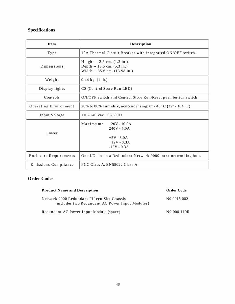
Specifications
Item Description
Type 12A Thermal Circuit Breaker with integrated ON/OFF switch.
DimensionsHeight -- 2.8 cm. (1.2 in.)Depth -- 13.5 cm. (5.3 in.)Width -- 35.6 cm. (13.98 in.)
Weight 0.44 kg. (1 lb.)
Display lights CS (Control Store Run LED)
Controls ON/OFF switch and Control Store Run/Reset push button switch
Operating Environment 20% to 80% humidity, noncondensing, 0° - 40° C (32° - 104° F)
Input Voltage 110 - 240 Vac 50 - 60 Hz
Power
Maximum: 120V - 10.0A240V - 5.0A
+5V - 3.0A+12V - 0.3A-12V - 0.3A
Enclosure Requirements One I/O slot in a Redundant Network 9000 intra-networking hub.
Emissions Compliance FCC Class A, EN55022 Class A
Order Codes
Product Name and Description Order Code
Network 9000 Redundant Fifteen-Slot Chassis N9-9015-002(includes two Redundant AC Power Input Modules)
Redundant AC Power Input Module (spare) N9-000-119R
48
Network 9000 Glossary
This glossary defines some commonly used terms in Network 9000 documentation,including this manual. Terms that appear in italics are defined elsewhere in theglossary.
ac input module The AC input module is a Network 9000 I/O module that providespower to the control storage of the chassis.
adapter card An adapter card is a Network 9000 I/O module that allows you to useLANbus I cards in a Network 9000 chassis.
chassis A Network 9000 chassis is the physical enclosure that contains the midplane, theslots for the processor modules and the I/O modules, and compartments for power suppliesand the AC input module. Two types of Network 9000 chassis are available: a six-slotchassis with compartments for two power supplies and a fifteen-slot chassis withcompartments for five power supplies.
chassis management commands Chassis management commands are a set ofcommands that reference chassis slots and power supplies, and can change the operationallink map, the status and parameters of initialization records, and reset processor modulesand power supplies. Network managers can use these commands to manage moduleslocally or remotely, without using the initialization configuration menu.
configuration menu see initialization configuration menu.
control storage The chassis provides control storage that contains slot-specificinformation, as well as the three initialization records for the processor modules in eachchassis slot.
dump file A dump file is a file that resides on a dump server, which is a host on thenetwork. If a processor module fails for some reason, it sends the contents of its memory tothe dump server, which create the dump file. Xyplex field personnel can then analyze thecontents of the dump file to diagnose the failure.
Ethernet An Ethernet, as defined by the IEEE 802.3 standard, is a type of local areanetwork (LAN). The Network 9000 midplane supports three separate Ethernet segments.
firmware Firmware is a type of program that resides in read-only memory (ROM).The firmware in a Network 9000 processor module contains an initialization programwhich begins executing automatically when you power on a processor module.
0023 49
Glossary
flash card See memory card.
initialization configuration menu An initialization configuration menu is a set ofscreens which display fields with values for initialization parameters, including the linkselection, protocols, and the software load image filename. The firmware on the processormodule prompts you to accept or change the values in each field. You can then save thechanges or reset the parameters to their default values. You can also change theseparameters with chassis management commands.
To start up the initialization configuration menu, follow these steps:
1. Press the Reset button on the front of the processor module once.
2. Press the Reset button again, and hold the button in. With the button held in, observe the front panel lights. The lights should flash in sequence from left to rightand then from right to left. At the end of this sequence, release the Reset button. Theprocessor module runs the standard self-test diagnostics, which last about 20 seconds.
3. Press the <Return> key a few times at the terminal connected to the port when the self test has completed; the Run light flashes rapidly. This causes the serial port to set the port speed, or baud rate, automatically (autobaud). Once the processor module has selected a port speed, it generates a message similar to this for a terminal server:
Terminal Server, Type xx, Rev xEthernet address 08-00-87-xx-xx-xx, port 1Configuration in progress. Please wait.
4. Enter the password ACCESS (note that there is no prompt). The main initialization
configuration menu appears on the screen.
initialization parameters Initialization parameters are characteristics thatdetermine how and where the processor module obtains the software load image andparameter file it needs to become operational. Initialization parameters reside in aninitialization record, and include load and dump protocols, load image filenames, theInternet addresses of gateways and load hosts, and the status of the initialization record.
initialization record An initialization record contains a set of initializationparameters, and resides is the control storage of the chassis. Each slot has threeinitialization records: primary, secondary, and tertiary. An initialization record can beenabled or disabled. If it is enabled, the processor module can use it to obtain initializationparameters.
I/O module An I/O module is a Network 9000 component that provides links to thenetwork and cabling. Terminal servers, LAN bridge/routers, WAN bridge/routers, andmanaged concentrators consist of a processor module and an I/O module. Unmanaged10BASE-T concentrators consist of an I/O module only.
50 0023
Glossary
LAN LAN is an acronym for Local Area Network.
LANbus I card A LANbus I card is part of the Xyplex MAXserver family of products,including terminal servers, bridges, and routers. The Network 9000 adapter card allowsyou to use LANbus cards in a Network 9000 chassis.
LIC A LAN Interface Card (LIC) is a component of the Network 9000 chassis whichprovides a connection to an external LAN for Ethernet Link 1 on terminal servers andWAN bridge/routers.
link A link is a connection to either a midplane Ethernet segment or an externalnetwork. Different Network 9000 products have different numbers and types of links. Forexample, a terminal server has one Ethernet link; a WAN bridge/router has one Ethernetlink and four WAN links.
link map A link map specifies the connections for all the links on a Network 9000managed concentrator, terminal server, LAN bridge/router,or WAN bridge/router.Network managers can change the link map through the initialization configurationmenu, and with chassis management commands or SNMP during operation.
link selection The link selection is a specific connection to either a midplane Ethernetsegment or an external network that the processor module uses to obtain the software loadimage and parameter file from the network, or to send information to a dump file.
load image see software load image
local management bus (LMB) The local management bus (LMB) is a transportsystem that is part of the chassis midplane. The LMB transports managementinformation among chassis slots, and allows you to monitor the modules in differentchassis slots, and the power supplies. The LMB operates automatically, and users do notneed to enable or manage it.
local slot The local slot is the slot in the chassis holding the processor module where youare logged on.
memory card A memory card is a type of media which contains a software load imageand, optionally, operational parameters for a Network 9000 processor module. Two types ofmemory cards exist: "Flash" cards, which are readable and writeable, and can beupgraded to newer versions of software, and "ROM" or "OTP" cards, which are read-only,and cannot be upgraded to newer versions of software. Flash cards may includeoperational parameters, and ROM cards do not include operational parameters.
midplane The midplane is a hardware component in the middle of the Network 9000chassis. It connects the processor module and the I/O module of a Network 9000 product.Independent I/O modules also plug into the midplane. The midplane supports threeinternal Ethernet segments, four Token Ring Segments, and two FDDI segments.
midplane Ethernet segment A midplane Ethernet segment is one of the threeEthernet LANs that the Network 9000 supports for managed concentrators, terminalservers, LAN bridge/routers, or WAN bridge/routers.
0023 51
Glossary
Network 9000™ Intra-Networking Hub A Xyplex Network 9000 Intra-networkingHub is a family of products and components that includes chassis, processor modules, I/Omodules, power supplies, and software. Together, these products provide highly reliableconnections to local and remote resources through LAN and WAN links. The Network9000 Intra-Networking Hub can support many different network configurations, andnetwork managers can adapt it to suit the needs of different users and computingenvironments.
operational parameters Operational parameters are characteristics that determinehow a Network 9000 processor module operates after initialization. Some operationalparameters are specific to each product, and the network manager can change them withcommands specific to that product. Others are common to all processor modules in thechassis, such as the link map, and a network manager can change them with chassismanagement commands.
parameter file A parameter file is a file which contains the operational characteristicsfor a processor module. These include the link map, the Internet address, security options,services, and port characteristics for terminal servers. Parameter files can reside on aparameter server, which is a host on the network, or a flash memory card.
power supply A power supply is a component of the Network 9000 chassis which suppliespower to the modules in the chassis. The Network 9000 chassis supports two types of powersupplies: model PS/130 managed power supplies and model PS/120 unmanaged powersupplies. Network managers can configure power supplies for redundancy, so that if onepower supply fails the others will compensate for the power loss and the modules willcontinue to operate without interruption.
processor module A processor module is a Network 9000 component that includes thecentral processor for the unit and the operational software and parameters.
redundancy Redundancy is the ability of one component in a system to providealternate support if another component in the system fails. Network 9000 power suppliescan provide redundancy to the processor modules and I/O modules in the chassis. Forexample, if two power supplies in a five-slot chassis each provide adequate power to supportall the modules in the chassis, one power supply can compensate if the other one fails.
software load image A software load image is a program that contains the executablesoftware that makes a processor modules operational. A software load image can reside ona load server, which is a host on the network, another Xyplex product, or a memory card.
SCM The Single Chip Microcontroller (SCM) provides the interface between certainNetwork 9000 components and the local management bus (LMB). These componentsinclude the AC Input module, processor modules, I/O modules, and managed powersupplies.
SNMP The Simple Network Management Protocol (SNMP) is a standard Internet protocolthat specifies how network management information is carried through the network.
target slot A slot that you specify in a chassis management command line, other thanthe one where you are logged on.
52 0023

Glossary
type 1 option A Type 1 option is a Network 9000 product or a MAXserver family productwhich does not support chassis management commands, and has a link to midplaneEthernet segment A only.
type 2 option A type 2 option consists of a Network 9000 module or module set. Type 2options support chassis management commands and have l inks that can connect tomidplane Ethernet segment A, B, or C.
W A N WAN is an acronym for Wide Area Network. A Network 9000 WANBridge/Router has four WAN links.
0023 53