9000 series wireless keypad - digital monitoring products
TRANSCRIPT

FRI 2:52 PM
A CB D FE G IH J LK
V XWS UTP RQM ON
YZ ENT
ER
BAC
K
ALL RESET HOME
CHIME PERIM SLEEP
1 2 3 4
5 6 7 8
9 0 CMD
A
POWER
RMED
INSTALLATION AND PROGRAMMING GUIDE
9000 Series Wireless Keypad


TABLE OF CONTENTSAbout the Keypad ...................................... 1Features .............................................................................. 1What’s Included ............................................................... 1
Keypad Layout ............................................2
Enter Characters .........................................3Number Pad ..................................................................... 3Card Reader ..................................................................... 4Two-Button Panic Keys ................................................ 4Backlit Logo ..................................................................... 5User Options Menu ........................................................ 6
Backlighting Brightness .................................................. 6
Internal Speaker Tone ....................................................... 6
Internal Volume Level ....................................................... 6
Model Number .................................................................... 6
Serial Number ...................................................................... 6
Select a Location ........................................7
Install the Keypad .......................................8Remove the Cover ......................................................... 8Mount the Keypad ......................................................... 9Power the Keypad ........................................................10
Primary DC Power Supply ............................................ 10
Standby Battery ............................................................... 10
Pair the Keypad ......................................... 11Step 1: Enable Pairing at the Keypad ......................... 12
Step 2: Initiate Pairing at the Panel ............................ 12
Program the Panel .................................... 13Device Setup .......................................................................13
Program Keypad Options ........................ 15Keypad Options .................................................................15
Card Formats ...................................................................... 17
No Communication with Panel ...................................23
Keypad Language ............................................................24
Additional Programming (9063 only) .................25Proximity Credential Compatibility ..........................25
Program a Credential .....................................................25

Test the Keypad ....................................... 26Keypad Diagnostics ........................................................26
Exit Installer Options ...................................................... 27
End User Training .....................................28Keypad Arming and Disarming ..............................29
Area System Type ............................................................29
All/Perimeter System Type.......................................... 30
Home/Away System Type ............................................ 30
Keypad Entry Delay .....................................................31All Systems ..........................................................................31
Compatibility ............................................35Panel Models ..................................................................35Public Card Formats ...................................................35Credentials ......................................................................36
Product Specifications ............................37Patents .............................................................................37
Compliance Listing Specifications ........38Commercial Burglary ..................................................38
Certifications .............................................38Underwriters Laboratory (UL) Listed ..................38
FCC Information .......................................39
Industry Canada Information .................40

9000 Series Installation and Programming Guide | Digital Monitoring Products, Inc. 1
ABOUT THE KEYPADThe 9060 and 9063 are supervised keypads that provide installation flexibility. The backlit keys are easy to read and when the system is in alarm, both the keyboard and logo turn red.
Features• Custom 32-character full LCD
display
• Three 2-button panic keys
• Backlit keys
• Internal sounder
• Wall tamper protection
• Keypad turns red in alarm
• Wireless Encryption (requires a keypad with firmware Version 300 or higher and a panel with firmware Version 183 or higher)
• Built-in proximity card reader (Model 9063)
What’s Included• One wireless keypad mounted in a
Thinline™ housing
• One internal rechargeable 3.7 V lithium battery
• One 12 VDC Plug-in Power Supply
• Mounting hardware
Digital Monitoring Products, Inc | 9000 Series Installation and Programming Guide 2
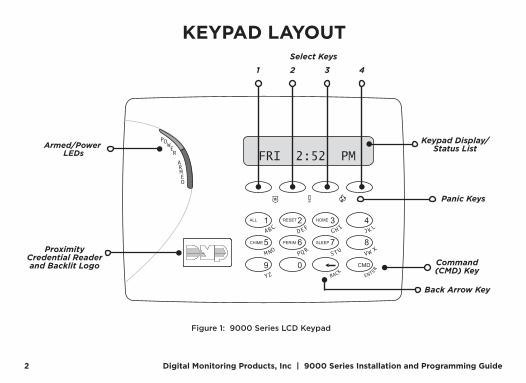
KEYPAD LAYOUT
FRI 2:52 PM
A CB D FE G IH J LK
V XWS UTP RQM ON
YZ ENT
ER
BAC
K
ALL RESET HOME
CHIME PERIM SLEEP
1 2 3 4
5 6 7 8
9 0 CMD
A
POWER
RMED
Armed/Power LEDs
Proximity Credential Reader and Backlit Logo
Keypad Display/Status List
Select Keys
Panic Keys
Command (CMD) Key
Back Arrow Key
1 432
Figure 1: 9000 Series LCD Keypad
9000 Series Installation and Programming Guide | Digital Monitoring Products, Inc. 3
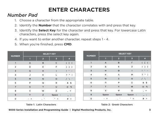
ENTER CHARACTERSNumber Pad
1. Choose a character from the appropriate table.
2. Identify the Number that the character correlates with and press that key.
3. Identify the Select Key for the character and press that key. For lowercase Latin characters, press the select key again.
4. If you want to enter another character, repeat steps 1 - 4.
5. When you’re finished, press CMD.
Table 1: Latin Characters
NUMBERSELECT KEY
1 2 3 4
1 A B C ( [ {
2 D E F ) ] }
3 G H I ! ^ ~
4 J K L ? “ |
5 M N O / \ `
6 P Q R & $
7 S T U @ %
8 V W X , =
9 Y Z Space : _ ;
0 - + . ‘ * < # >
Table 2: Greek Characters
NUMBERSELECT KEY
1 2 3 4
1 Α Β Γ ( [ {
2 Δ Ε Ζ ) ] }
3 Η Θ Ι ! ^ ~
4 Κ Λ Μ ? “ |
5 Ν Ξ Ο / \ `
6 Π Ρ Σ & $
7 Τ Υ Φ @ %
8 Χ Ψ Ω , =
9 Space Space Space : _ ;
0 - + . ‘ * < # >
Digital Monitoring Products, Inc | 9000 Series Installation and Programming Guide 4
Card ReaderWhen a proximity credential is presented to the 9063 internal reader, located behind the backlit logo, a beep tone is emitted to provide an audible acknowledgment of the credential read.
Two-Button Panic KeysAll keypads offer a panic key function that allows users to send panic, emergency, or fire reports to the central station in an emergency. Enable the panic key function in the keypad user menu. Place the supplied icon stickers below the top row select keys. The user must press and hold the two select keys for two seconds until a beep is heard.
Panic (left two select keys)—Zone 19 + Device Address Emergency Non-Medical (center two select keys)—Zone 29 + Device Address Fire (right two select keys)—Zone 39 + Device Address

9000 Series Installation and Programming Guide | Digital Monitoring Products, Inc. 5
Backlit LogoThe backlit logo indicates the armed status of the panel and the power and battery status of the keypad.
COLOR AND ACTIVITY ARMED STATUS DC POWER STATUS BATTERY STATUS PAIRED
Green Steady Disarmed OK OK Yes
Green Blinking Disarmed OK Fault Yes
Red Steady Armed OK OK No
Red Blinking Armed Fault OK No
Red/Green Alternating Armed OK Fault Unknown
No Light Unknown Fault Unknown Unknown
Table 3: Logo Color and Behavior

Digital Monitoring Products, Inc | 9000 Series Installation and Programming Guide 6
User Options MenuTo access the Options menu, press and hold the back arrow and CMD keys for 2 seconds.
Backlighting BrightnessAdjust the brightness, power and armed LEDs, green keyboard, and logo backlighting. At SET BRIGHTNESS, use the left and right select keys to adjust the brightness. The brightness reverts to maximum intensity whenever a key is pressed. If no keys are pressed and the speaker has not sounded for 10 seconds, the user-selected brightness restores.
Note: During primary power loss, the backlighting turns completely off after 10 seconds of no activity to conserve the standby battery.
Internal Speaker ToneAdjust the keypad internal speaker tone. At SET TONE, use the left select key to decrease the tone and the right select key to increase the tone.
Internal Volume LevelAdjust the keypad internal speaker volume for key presses and entry delay tone conditions. During alarm and trouble conditions, the volume is always at maximum level. At SET VOLUME LEVEL, use the left select key to decrease the volume and the right select key to increase the volume.
Model NumberDisplay the keypad model number, firmware version, and date.
Serial NumberDisplay the keypad’s serial number.
9000 Series Installation and Programming Guide | Digital Monitoring Products, Inc. 7
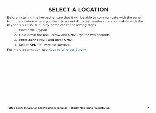
SELECT A LOCATIONBefore installing the keypad, ensure that it will be able to communicate with the panel from the location where you want to mount it. To test wireless communication with the keypad’s built-in RF survey, complete the following steps.
1. Power the keypad.
2. Hold down the back arrow and CMD keys for two seconds.
3. Enter 3577 (INST) and press CMD.
4. Select KPD RF (wireless survey).
For more information, see Keypad Wireless Survey.

Digital Monitoring Products, Inc | 9000 Series Installation and Programming Guide 8
INSTALL THE KEYPADRemove the CoverThe keypad housing is made up of two parts: the cover, which contains the circuit board and components, and the base.
To separate the keypad cover from the base, insert a flathead screwdriver into one of the slots on the bottom of the keypad and gently lift the screwdriver upward. Repeat with the other slot. Gently separate the cover from the base and set the cover containing the keypad components aside. See Figure 2.
1
Figure 2: Separate the Keypad Housing
Cover
Base
9000 Series Installation and Programming Guide | Digital Monitoring Products, Inc. 9
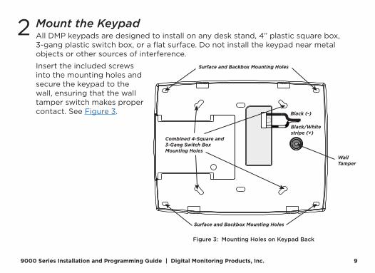
Mount the KeypadAll DMP keypads are designed to install on any desk stand, 4” plastic square box, 3-gang plastic switch box, or a flat surface. Do not install the keypad near metal objects or other sources of interference.
Insert the included screws into the mounting holes and secure the keypad to the wall, ensuring that the wall tamper switch makes proper contact. See Figure 3.
2
Black (-)
Black/White stripe (+)
WallTamper
Surface and Backbox Mounting Holes
Surface and Backbox Mounting Holes
Combined 4-Square and3-Gang Switch BoxMounting Holes
Figure 3: Mounting Holes on Keypad Back

Digital Monitoring Products, Inc | 9000 Series Installation and Programming Guide 10
3 Power the KeypadPrimary DC Power SupplyLocate the keypad near a wall outlet to allow connection of the Model 371-500 plug-in DC power supply. See Figure 4 for a diagram of the DC power supply connector. In addition to powering the keypad, the power supply also charges the internal back-up battery. The plug-in power supply includes a six foot cord. The cord can be lengthened but should be located within 100 feet of the keypad using 22 AWG wire.
Caution: Observe polarity when extending the power supply cord.
When the power supply connector is plugged into the keypad, the internal battery is automatically connected. The keypad can operate from battery only as long as the power supply connector is plugged into the keypad.
Standby BatteryThe keypad rechargeable battery provides 24 hours of backup battery power when primary DC power is unavailable. It is shipped already installed inside the keypad. The battery is intended for backup power only and not to operate the keypad on a daily basis. If the battery is low, or not plugged into the internal battery connector, a low battery condition is indicated by the panel when the battery falls below 3.62 VDC. To restore the keypad from a low battery state, the voltage must be above 3.62 VDC.
Black (-)
Black/White Stripe (+)
Figure 4: DC Power Supply Connector

9000 Series Installation and Programming Guide | Digital Monitoring Products, Inc. 11
PAIR THE KEYPADYou can program up to 7 wireless keypads in a panel with XR Series Version 191 (3/8/19) or higher and XT Series Version (11/15/19) or higher.
9000 Series wireless keypads can be programmed into the control panel by using the wireless keypad pairing operation or by entering the serial number in Device Setup.
The keypad logo is red when it is not paired to a panel. The keypad logo turns green when it is paired to a panel. If the light is not on, the keypad is not receiving DC power. For more information, refer to Table 3.
Note: If you’re programming the keypad as a device type manually, skip this section and go to Device Setup.
During pairing, unaddressed keypads are automatically assigned to the first open device address based on the order in which they are detected.

Digital Monitoring Products, Inc | 9000 Series Installation and Programming Guide 12
Step 1: Enable Pairing at the KeypadHold down the back arrow and CMD keys for two seconds. Enter 3577 (INST) and press CMD. Select KPD RF (wireless survey). For more information, see Keypad Wireless Survey.
Step 2: Initiate Pairing at the PanelSelect one of the following methods to initiate pairing with the panel:
Pair Automatically (XTL Series Only)Reset or power up the panel. For 60 seconds, the panel listens for wireless keypads that are in wireless survey and have not been programmed or paired to another panel.
Pair Manually (Any Compatible Panel Model)Reset the panel 3 times within 12 seconds, allowing the panel’s Keypad Bus LEDs to turn back on between each reset.
9000 Series Installation and Programming Guide | Digital Monitoring Products, Inc. 13
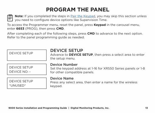
PROGRAM THE PANELNote: If you completed the steps in Pair the Keypad, you may skip this section unless you need to configure device options like Supervision Time.
To access the Programmer menu, reset the panel, press Keypad in the carousel menu, enter 6653 (PROG), then press CMD.
After completing each of the following steps, press CMD to advance to the next option. Refer to the panel programming guide as needed.
DEVICE SETUPAdvance to DEVICE SETUP, then press a select area to enter the setup menu.
Device NumberSet the keypad address at 1-16 for XR550 Series panels or 1-8 for other compatible panels.
Device NamePress any select area, then enter a name for the wireless keypad.
DEVICE SETUP
DEVICE SETUPDEVICE NO: -
DEVICE SETUP*UNUSED*

Digital Monitoring Products, Inc | 9000 Series Installation and Programming Guide 14
Device TypeFor use as a standard keypad, select KPD. For use as an access control keypad, press any select area, then select DOOR.
Communication TypePress any select area, then select WLS (Wireless) as the communication type.
Serial NumberEnter the eight-digit wireless serial number. Range is 14500000-14999999.
Supervision TimePress any select area and choose a supervision time. Options are 0, 60, or 240 minutes.
DEVICE SETUPTYPE: KEYPAD
DEVICE SETUPCOMM TYPE: WLS
DEVICE SETUPSERIAL#:-
DEVICE SETUPSUPRVSN TIME: 240
Configure additional options as needed. To configure custom card options for the keypad, do not program CARD OPTIONS in Device Setup.

9000 Series Installation and Programming Guide | Digital Monitoring Products, Inc. 15
PROGRAM KEYPAD OPTIONSKeypad Options and Keypad Diagnostic menus allow install and service technicians to configure and test keypad operation. To access the installer options:
Hold down the back arrow and CMD keys for two seconds. At SET BRIGHTNESS, enter 3577 (INST) and press CMD.
The display changes to KPD OPT KPD DIAG and STOP. The Keypad Options menu allows you to set the keypad address, select Supervised or Unsupervised mode, change the default keypad message, selectively enable the 2-button Panic keys, Bypass, REX, and set entry card options.
Note: All programming options display on all keypads. However, actual operation for some programming options is restricted to the appropriate model.
KEYPAD OPTIONSTo program keypad options, press KPD OPT.
Serial NumberThe keypad displays its serial number.
KPD KPD KPDOPT DIAG RF STOP
SERIAL #:XXXXXXXX
Digital Monitoring Products, Inc | 9000 Series Installation and Programming Guide 16
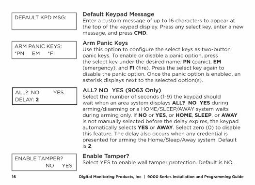
Default Keypad MessageEnter a custom message of up to 16 characters to appear at the top of the keypad display. Press any select key, enter a new message, and press CMD.
Arm Panic KeysUse this option to configure the select keys as two-button panic keys. To enable or disable a panic option, press the select key under the desired name: PN (panic), EM (emergency), and FI (fire). Press the select key again to disable the panic option. Once the panic option is enabled, an asterisk displays next to the selected option(s).
ALL? NO YES (9063 Only)Select the number of seconds (1-9) the keypad should wait when an area system displays ALL? NO YES during arming/disarming or a HOME/SLEEP/AWAY system waits during arming only. If NO or YES, or HOME, SLEEP, or AWAY is not manually selected before the delay expires, the keypad automatically selects YES or AWAY. Select zero (0) to disable this feature. The delay also occurs when any credential is presented for arming the Home/Sleep/Away system. Default is 2.
Enable Tamper?Select YES to enable wall tamper protection. Default is NO.
DEFAULT KPD MSG:
ARM PANIC KEYS:*PN EM *FI
ALL?: NO YESDELAY: 2
ENABLE TAMPER? NO YES

9000 Series Installation and Programming Guide | Digital Monitoring Products, Inc. 17
CARD FORMATSSelect DMP to allow credentials that use a 26-45 bit data string. The menu advances to REQUIRE SITE.
Select CUSTOM to disable DMP format and program slots 1-8 as needed. The menu advances to FORMAT NO.
Select ANY to allow all Wiegand card reads to activate the door strike relay. The door strike relay is activated for the length of time programmed in ZN 3 REX TIME. No user code information is sent to the panel. The menu advances to NO COMM WITH PNL.
The default card format is DMP.
CARD FORMATSDMP CUSTOM ANY

Digital Monitoring Products, Inc | 9000 Series Installation and Programming Guide 18
Card Format NumberSelect the slot number (1-8) that you want to program for a custom non-DMP card format. The format that is programmed into slot 1 is the default format. In the event that a card with an unrecognized format is used, that card will be read in the format that is programmed in slot 1. To restrict card reads to specific formats, only program slots 2-8.
See Public Card Formats for some publicly available card formats that can be used with the keypad. Other private or custom formats may also be compatible. Please contact the credential supplier or manufacturer for the bit structure.
CARD FORMATSFORMAT NO: -
Note: If you select slot 1 and you are upgrading from XR panel version 182 or earlier, FORMAT NAME will automatically be named SINGLE CARD FORMAT and WIEGAND CODE LENGTH will default to 45.

9000 Series Installation and Programming Guide | Digital Monitoring Products, Inc. 19
Format NamePress any select area to rename the card format. Press CMD to save and advance.
Wiegand Code LengthWhen using a custom credential, enter the total number of bits to be received in Wiegand code including parity bits.
Press any select key or area to enter a number between 1-255 to equal the number of bits. Default is 26 bits.
An access card contains data bits for a site code, user code, and start/stop/parity bits. The starting position, location, and code length must be determined and programmed into the keypad. See Figure 5.
FORMAT NAME*UNUSED*
WIEGAND CODELENGTH: 26
0 1 1 1 0 1 0 1 1 0 1 1 0 1 0 1 0 0 0 1 1 0 0 1 1 1
First BitReceived
Position = 0
Site CodePosition = 1Length = 8
User CodePosition = 9Length = 16
Last BitReceived
Position = 25
Example: Wiegand Code Length = 26 bits
Figure 5: Wiegand Data Stream Bit Location

Digital Monitoring Products, Inc | 9000 Series Installation and Programming Guide 20
Site Code Position and LengthEnter the site code start position and length in the data string. Press select area 2 to clear the site code start position and enter a number between 0-255. Press CMD to save. Default is 1.Press select area 4 to clear the site code length and enter a number between 1-24. Press CMD to save. Default is 8.
User Code Position and LengthDefine the user code start bit position and length. Press select area 2 to clear the user code position and enter a number between 0-255. Press CMD to save. Default is 9.
Press select area 4 to clear the user code length and enter a number between 16-64. Press CMD to save. The default is the DMP value of 16.
SITE CODEPOS: 1 LEN: 8
USER CODEPOS: 9 LEN: 16

9000 Series Installation and Programming Guide | Digital Monitoring Products, Inc. 21
Require Site CodePress the top row select key or area under YES to use a site code and press CMD to view the site code entry display. Press NO to advance to NO OF USER CODE DIGITS. Default is NO.
In addition to user code verification, door access is only granted when any one site code programmed at the SITE CODE ENTRY option matches the site code received in the Wiegand string.
Site Code DisplayYou can program up to eight 8-digit site codes. The site code range is 0-16,777,214.
In the keypad display, enter site code 1 and press CMD. The display will ask for site code 2 followed by site code 3 and so on. When you have selected the site code you want to change, press CMD.
REQUIRE SITECODE: NO YES
SITE CODE 1:

Digital Monitoring Products, Inc | 9000 Series Installation and Programming Guide 22
Number of User Code DigitsThe keypad recognizes user codes from 4-12 digits long. Press any top row select key or area to enter a user code digit length. This number must match the user code number length being programmed in the panel. The device will recommend a number of user code digits based on the user code length. Default is 5.
All bits are read and converted into a decimal number string. The number string is left padded with 0 (zero) if needed for long user code lengths.
Example: # decoded 1234567
10 digits 0001234567
4 digits 4567
NO OF USER CODE DIGITS: 5

9000 Series Installation and Programming Guide | Digital Monitoring Products, Inc. 23
NO COMMUNICATION WITH PANELDefine the relay action when communication with the panel has not occurred for 5 seconds: OFF, SITE, ANY, ON, or LAST. Default is OFF. Press any select key or area to change the default relay action:
Press the first select key or area to choose OFF (Relay Always Off). The relay does not turn on when any Wiegand string is received. OFF does not affect any REX operation. If communication is lost during a door strike, the relay remains on for the door strike duration but turns off at the end of the door strike timer.
Press the second select key or area to choose SITE (Accept Site Code). Door access is granted when the Wiegand site code string received matches any site code programmed at Site Code. Refer to “Require Site Code” for more information.
Press the third select key or area to choose ANY (Any Wiegand Read). Access is granted when any Wiegand string is received.
Press the fourth select key or area to choose ON (Relay Always On). The relay is always on.
Press CMD to display additional actions. Press the first select key or area to choose LAST (Keep Last State). The relay remains in the same state and does not change when communication is lost.
NO COMM WITH PNLOFF
OFF SITE ANY ON
OFF SITE ANY ON
OFF SITE ANY ON
OFF SITE ANY ON
LAST

Digital Monitoring Products, Inc | 9000 Series Installation and Programming Guide 24
KEYPAD LANGUAGEDefine the keypad’s language. Default is ENGLSH.
Press any select key to change the language options.
Press select key 1 to select English. Press select key 2 to select Spanish. Press select key 3 to select French. Press select key 4 to select Dutch.
Press CMD to advance the language options.
Press select key 1 to select Greek. Press select key 2 to select Czech.
KYPD LANGUAGE:LANG: ENGLSH
KYPD LANGUAGE:ENG SPN FRN DUT
KYPD LANGUAGE:EΛΛ CZK

9000 Series Installation and Programming Guide | Digital Monitoring Products, Inc. 25
Additional Programming (9063 only)9063 keypads allow users to present a proximity credential to the built-in proximity reader. Users can also manually enter their user code into the keypad. The keypad verifies the user code and its authority with the panel.
Proximity Credential Compatibility DMP keypads with internal proximity readers are compatible with most standard 125 kHz proximity credentials. For a list of publicly supported card formats, see Public Card Formats.
Note: Some proximity credentials are not compatible with DMP proximity keypads. Test the intended proximity credentials with the application before installation. DMP does not guarantee compatibility with credentials not purchased from DMP.
Program a Credential1. Access the User Menu by pressing CMD until MENU? NO YES displays. Choose
YES, and present your proximity credential to the reader or manually enter your user code at the keypad.
2. Press CMD until USER CODES? displays.
3. Press any select key. Choose ADD.
4. At ENTER CODE: -, present the credential to the reader. The keypad works by reading the user code from the data string sent by the access control reader.

Digital Monitoring Products, Inc | 9000 Series Installation and Programming Guide 26
KEYPAD DIAGNOSTICSPress the select key under KPD DIAG. The keypad lights all display segments and illuminates the keyboard in red. The display backlighting then changes to green. The keypad alternates between these two states for approximately two minutes. Press CMD at any time to begin testing individual keys.
Test Individual KeysThe display changes to PRESS KEY TO TEST. This option tests each key on the keyboard to ensure it is operating properly. Press and hold each key for two seconds. The key number being held appears in the display. Verify the correct number displays before testing the next key.
KPD KPDOPT DIAG STOP
PRESS KEY TOTEST
TEST THE KEYPADTest the keypad to ensure alarm backlighting, individual shortcut keys, and any programmed zones work. To begin testing, access the Installer Options menu. Hold down the back arrow and CMD keys at the same time until SET BRIGHTNESS displays. Enter 3577 and press CMD.
9000 Series Installation and Programming Guide | Digital Monitoring Products, Inc. 27
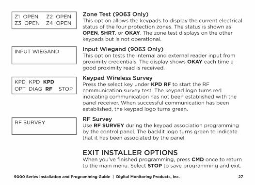
Zone Test (9063 Only)This option allows the keypads to display the current electrical status of the four protection zones. The status is shown as OPEN, SHRT, or OKAY. The zone test displays on the other keypads but is not operational.
Input Wiegand (9063 Only)This option tests the internal and external reader input from proximity credentials. The display shows OKAY each time a good proximity read is received.
Keypad Wireless SurveyPress the select key under KPD RF to start the RF communication survey test. The keypad logo turns red indicating communication has not been established with the panel receiver. When successful communication has been established, the keypad logo turns green.
RF SurveyUse RF SURVEY during the keypad association programming by the control panel. The backlit logo turns green to indicate that it has been associated by the panel.
EXIT INSTALLER OPTIONSWhen you’ve finished programming, press CMD once to return to the main menu. Select STOP to save programming and exit.
Z1 OPEN Z2 OPEN Z3 OPEN Z4 OPEN
INPUT WIEGAND
KPD KPD KPDOPT DIAG RF STOP
RF SURVEY

Digital Monitoring Products, Inc | 9000 Series Installation and Programming Guide 28
This section covers:
• Keypad Arming and Disarming
• Keypad Entry Delay
All of the examples displayed assume that CLOSING CODE is enabled in panel programming.
END USER TRAINING

9000 Series Installation and Programming Guide | Digital Monitoring Products, Inc. 29
Keypad Arming and DisarmingArea System Type
1. Press CMD until the keypad displays ARM DISARM.
2. Press the select key under the preferred option.
3. The keypad displays ENTER CODE: -. The user presents their card to the reader.
Once validated by the system, all areas assigned to that code arm or disarm automatically. See Figure 6.
Figure 6: Area Arming and Disarming
ABC SECURITYARM DISARM
ABC SECURITYENTER CODE: –
ABC SECURITYALL? NO YES
Select NO to arm or disarm individual areas. Select YES, or simply wait, to automatically arm or disarm all areas for which you are authorized.

Digital Monitoring Products, Inc | 9000 Series Installation and Programming Guide 30
All/Perimeter System TypePresent the card to the reader or press CMD, the keypad displays DISARM? or PERIM ALL (when arming). Press the select key under the desired option. The keypad displays ENTER CODE: -. Present the card to the reader. Once validated by the system, the selected areas arm or disarm automatically.
Home/Away System TypePresent your card to the reader. If the system is armed, once the card is validated, all areas are disarmed and the keypad displays ALL SYSTEM OFF. If the system is disarmed when you present your card, once the card is validated, HOME SLEEP AWAY displays. Manually select HOME, SLEEP, AWAY or after a short time-out, all areas automatically arm in the AWAY mode.
PERIM ALL
The system arms or disarms the areas andactivates the door strike relay on the 7073 or 7073A keypad.
Figure 7: All Perimeter Arming and Disarming

9000 Series Installation and Programming Guide | Digital Monitoring Products, Inc. 31
Keypad Entry DelayAll SystemsOnce the entry delay starts, the keypad sounds an entry tone and displays ENTER CODE: - . Present your card to the reader. Once validated, the system disarms all areas accessible by you. Area systems provide a delay to allow selected areas only to be disarmed. See Keypad Arming and Disarming.
Entry delay starts.The System disarms the area and activates the Door Strike Relay.
ABC SECURITYENTER CODE: –
Figure 8: Entry Delay

Digital Monitoring Products, Inc | 9000 Series Installation and Programming Guide 32
Replace the BatteryDMP recommends replacing the battery every 3 years under normal use. Refer to Figure 9 and Figure 10 when replacing the battery.
Remove the Keypad PCB1. Disconnect the power supply.
2. Loosen the top PCB snaps.
3. Lean the keypad backwards and lift out from the bottom PCB snaps.
Battery Replacement1. Disconnect the battery lead connector from the keypad battery header.
2. Remove the standby battery from the PCB.
3. Observe polarity and connect the battery connector to the keypad battery header.
4. Using double-sided tape, place the new battery on the keypad PCB.
5. Properly dispose of the used battery.
Caution: Risk of fire, explosion, and burns. Do not disassemble, heat above 212°F (100°C), or incinerate.
Install the Keypad PCB1. Ensure the keyboard is in place, then insert the PCB into the bottom snaps.
2. Line up the alignment post with the hole in the PCB.
3. Press the PCB into the top snaps to secure in place.
4. Place the keypad cover back onto the base and snap into place.

9000 Series Installation and Programming Guide | Digital Monitoring Products, Inc. 33
Top PCB Snaps
Bottom PCB Snaps
PCB Alignment Post
4 Position Header
Figure 9: PCB Snaps

Digital Monitoring Products, Inc | 9000 Series Installation and Programming Guide 34
SN LEV
FRI 2:52 PMRED
BLACK
DM
P Li-ion Polymer C
ell M
odel: 9000BATBattery R
ating: 3.7V 800 mAh
Batch Code: 12-2008
Part Num
ber: BT-0031
Only use specified charger
Do not short circuit
Do not disassem
bleD
o not expose to high temperatures
Do not incinerate
Dispose of properly
KEY 0 KEY 1 KEY 2 KEY 3
KEY 4 KEY 5 KEY 6 KEY 7
KEY 8 KEY 9 KEY 10 KEY 11
KEY 12 KEY 13 KEY 14 KEY 15
Figure 10: Battery Location and PCB Connection

9000 Series Installation and Programming Guide | Digital Monitoring Products, Inc. 35
COMPATIBILITYPanel ModelsAll DMP panels and 1100 Series Wireless Receivers are compatible with the 9000 Series.
Wireless encryption requires keypad firmware Version 300 or higher and panel firmware Version 183 or higher.
Public Card FormatsCARD FORMAT WIEGAND
CODE LENGTHSITE CODE POSITION
SITE CODE LENGTH
USER CODE POSITION
USER CODE LENGTH
USER CODE DIGITS
H10301 26-Bit 26 1 8 9 16 5
H10302 37-Bit w/o FAC 37 0 1 1 35 11
H10304 37-Bit w/ FAC 37 1 16 17 19 6
Farpointe 39-Bit 39 1 17 18 20 7
Corporate 1000 35-Bit 35 2 12 14 20 6
Corporate 1000 48-Bit 48 2 22 24 23 7
Digital Monitoring Products, Inc | 9000 Series Installation and Programming Guide 36
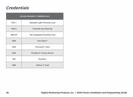
Credentials
125 kHz PROXIMITY CREDENTIALS
PSC-1 Standard Light Proximity Card
PSK-3 Proximity Key Ring Tag
PSM-2P ISO Imageable Proximity Card
1306 Prox Patch™
1326 Proxcard II® Card
1346 ProxKey III® Access Device
1351 ProxPass®
1386 IsoProx II® Card

9000 Series Installation and Programming Guide | Digital Monitoring Products, Inc. 37
PRODUCT SPECIFICATIONSOperating Voltage 12 VDC, 500 mA
Standby Battery
Model 9000BAT Voltage 3.7 VDC Capacity 800 Ah Type Lithium Polymer, Rechargeable Standby Time 24 Hours
Frequency Range 905-924 MHz
Dimensions 7.00” W x 5.25” H x 0.50” D (17.8 cm x 13.3 cm x 1.3 cm)
Color White
Housing Material Flame-Retardant ABS
PatentsU.S. Patent No. 7,239,236

Digital Monitoring Products, Inc | 9000 Series Installation and Programming Guide 38
COMPLIANCE LISTING SPECIFICATIONSCommercial Burglary
• Set the Enable Tamper option to YES for all listed commercial burglary applications.
• Use DMP proximity cards only for listed applications.
CERTIFICATIONSANSI/SIA CP-01-2010 False Alarm ReductionFCC Part 15 RFID Reader FCC ID: CCKPC0126
Industry Canada: 5251A-PC0126
Underwriters Laboratory (UL) Listed• ANSI/UL 1023 Household Burglar Alarm System Units
• ANSI/UL 1610 Central Station Burglar Alarm Units
• ANSI/UL 985 Household Fire Warning System
9000 Series Installation and Programming Guide | Digital Monitoring Products, Inc. 39
FCC INFORMATIONThis device complies with Part 15 of the FCC Rules. Operation is subject to the following two conditions:
1. This device may not cause harmful interference, and
2. This device must accept any interference received, including interference that may cause undesired operation.
Changes or modifications made by the user and not expressly approved by the party responsible for compliance could void the user’s authority to operate the equipment.
Note: This equipment has been tested and found to comply with the limits for a Class B digital device, pursuant to part 15 of the FCC Rules. These limits are designed to provide reasonable protection against harmful interference in a residential installation. This equipment generates, uses and can radiate radio frequency energy and, if not installed and used in accordance with the instructions, may cause harmful interference to radio communications. However, there is no guarantee that interference will not occur in a particular installation. If this equipment does cause harmful interference to radio or television reception, which can be determined by turning the equipment off and on, the user is encouraged to try to correct the interference by one or more of the following measures:
• Reorient or relocate the receiving antenna.
• Increase the separation between the equipment and receiver.
• Connect the equipment into an outlet on a circuit different from that to which the receiver is connected.
• Consult the dealer or an experienced radio/TV technician for help.

Digital Monitoring Products, Inc | 9000 Series Installation and Programming Guide 40
INDUSTRY CANADA INFORMATIONThis device complies with Industry Canada License-exempt RSS standard(s). Operation is subject to the following two conditions:
1. This device may not cause interference, and
2. This device must accept any interference, including interference that may cause undesired operation of the device.
Le présent appareil est conforme aux CNR d’Industrie Canada applicables aux appareils radio exempts de licence. L’exploitation est autorisée aux deux conditions suivantes:
1. l’appareil ne doit pas produire de brouillage, et
2. l’utilisateur de l’appareil doit accepter tout brouillage radioélectrique subi, même si le brouillage est susceptible d’en compromettre le fonctionnement.
This system has been evaluated for RF Exposure per RSS-102 and is in compliance with the limits specified by Health Canada Safety Code 6. The system must be installed at a minimum separation distance from the antenna to a general bystander of 7.87 inches (20 cm) to maintain compliance with the General Population limits.
L’exposition aux radiofréquences de ce système a été évaluée selon la norme RSS-102 et est jugée conforme aux limites établies par le Code de sécurité 6 de Santé Canada. Le système doit être installé à une distance minimale de 7.87 pouces (20 cm) séparant l’antenne d’une personne présente en conformité avec les limites permises d’exposition du grand public.


LT-1107 21332 1.04 © 2021 Digital Monitoring Products, Inc.