installing the power components - cisco
TRANSCRIPT
Installing the Power Components
This chapter provides an overview of the AC and DC power systems and how to install the power modulesand input power cables into the Cisco NCS 6000 Fabric Card Chassis (FCC). For information about removingpower components, see the Removing the Power Components section.
• Power System Overview, page 1
• Installing the Power Modules and Input Power Cables, page 11
• Powering On and Powering Off the Fabric Card Chassis, page 23
Power System OverviewThe Cisco NCS 6000 FCC can be configured with either an AC input power system or a DC input powersystem. Site power requirements differ, depending on the source voltage used.
For information about power safety requirements, see the Regulatory Compliance and Safety Information forthe Cisco Network Convergence System 6000 Series Routers.
PrerequisitesFollow these precautions and recommendations when planning power connections to the FCC:
• Check the power at your site before installation to ensure that you are receiving clean power (free ofspikes and noise). Install a power conditioner, if necessary.
• Install proper grounding to avoid damage from lightning and power surges.
Installing the Fabric Card Chassis Ground CableThe FCC has two safety earth ground connections. You can connect the central office ground system or interiorequipment grounding system to either of these grounding points on the rear side of the FCC. One chassisground is located near the top of the FCC and one chassis ground is located at the bottom of the FCC. These
Cisco Network Convergence System 6000 Fabric Card Chassis Hardware Installation Guide 1
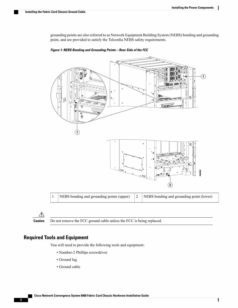
grounding points are also referred to as Network Equipment Building System (NEBS) bonding and groundingpoint, and are provided to satisfy the Telcordia NEBS safety requirements.
Figure 1: NEBS Bonding and Grounding Points—Rear Side of the FCC
NEBS bonding and grounding point (lower)2NEBS bonding and grounding points (upper)1
Do not remove the FCC ground cable unless the FCC is being replaced.Caution
Required Tools and EquipmentYou will need to provide the following tools and equipment:
• Number-2 Phillips screwdriver
• Ground lug
• Ground cable
Cisco Network Convergence System 6000 Fabric Card Chassis Hardware Installation Guide2
Installing the Power ComponentsInstalling the Fabric Card Chassis Ground Cable
• Crimping tool and lug specific die
• 3/8-inch drive torque wrench rated to include 30 in-lb (3.39 N-m)
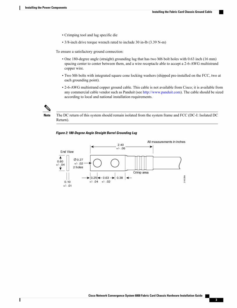
To ensure a satisfactory ground connection:
• One 180-degree angle (straight) grounding lug that has two M6 bolt holes with 0.63 inch (16 mm)spacing center to center between them, and a wire receptacle able to accept a 2-6-AWG multistrandcopper wire.
• Two M6 bolts with integrated square cone locking washers (shipped pre-installed on the FCC, two ateach grounding point).
• 2-6-AWG multistrand copper ground cable. This cable is not available from Cisco; it is available fromany commercial cable vendor such as Panduit (see http://www.panduit.com). The cable should be sizedaccording to local and national installation requirements.
The DC return of this system should remain isolated from the system frame and FCC (DC-I: Isolated DCReturn).
Note
Figure 2: 180-Degree Angle Straight Barrel Grounding Lug
Cisco Network Convergence System 6000 Fabric Card Chassis Hardware Installation Guide 3
Installing the Power ComponentsInstalling the Fabric Card Chassis Ground Cable
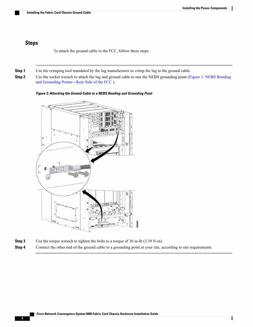
StepsTo attach the ground cable to the FCC, follow these steps:
Step 1 Use the crimping tool mandated by the lug manufacturer to crimp the lug to the ground cable.Step 2 Use the socket wrench to attach the lug and ground cable to one the NEBS grounding point (Figure 1: NEBS Bonding
and Grounding Points—Rear Side of the FCC ).
Figure 3: Attaching the Ground Cable to a NEBS Bonding and Grounding Point
Step 3 Use the torque wrench to tighten the bolts to a torque of 30 in-lb (3.39 N-m).Step 4 Connect the other end of the ground cable to a grounding point at your site, according to site requirements.
Cisco Network Convergence System 6000 Fabric Card Chassis Hardware Installation Guide4
Installing the Power ComponentsInstalling the Fabric Card Chassis Ground Cable
AC Power System
Overview of the AC Power SystemAnAC-powered Cisco NCS 6000 FCC contains four AC power trays that are part of the FCC power enclosure(Figure 1). The upper two power trays (PT0 and PT1) are referred to as PS0, and the lower two power trays(PT2 and PT3) are referred to as PS1. Figure 3. Each set of power trays has a power control module (PCM)with its own I/O power switch.
Each AC power tray has three slots for PMs. The AC power trays are field-replaceable (after power down),however the PMs are hot-swappable.
Each inserted AC PM requires a single-phase, 50 to 60 Hz, 200 to 240 VAC input. Input current is variableand based on facility minimum voltage. For N+N redundancy, power feeds A must power the upper two ACpower trays and power feeds B must power the lower two AC power trays (not all of the power module baysneed to be filled). This allows the system to balance its load across each set of power trays and across thepower modules within each tray.
The AC power system requires single-phase AC input power to each inserted PM. If you have a 3-phase ACDelta or AC Wye at your equipment, a Cisco NCS power distribution unit (PDU) is required to convert3-phase AC input power to single-phase AC input power system.
If you plan to use a three-phase AC PDUwe recommend that you install three AC PMs in each AC powertray to maintain a balanced three-phase power load.
Note
We recommend that you use appropriate short-circuit protection in compliance with national and localelectrical codes.
Note
Installing an AC Power Distribution UnitThe AC PDU converts three-phase AC input power to single-phase AC input power that connects directly tothe rear of each PM. The AC PDU includes either an AC Delta (Cisco PID NCS-PDU-DELTA) or AC Wye
Cisco Network Convergence System 6000 Fabric Card Chassis Hardware Installation Guide 5
Installing the Power ComponentsAC Power System

(Cisco PID NCS-PDU-WYE) power interface, and has power input and power output cords entering andexiting the box.
Figure 4: Cisco NCS-PDU
Output cord4Rack mounting ears1
Two PDUs5Rack tray2
Input cord3
For detailed information on AC PDUs, see the Cisco CRS 3-Phase AC Power Distribution Unit InstallationGuide.
Mounting the PDU
The AC PDU mounting bracket holds two AC PDUs. The mounting bracket can be attached to both sides ofthe FCC by using the existing screws that hold the side panels on (Figure 5: AC PDU Bracket Attached tothe Side of the FCC). The PDUs are attached to the mounting brackets with four M5 screws per AC PDU.
Cisco Network Convergence System 6000 Fabric Card Chassis Hardware Installation Guide6
Installing the Power ComponentsAC Power System
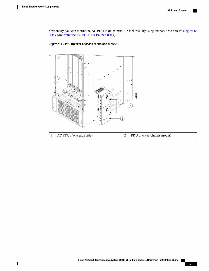
Optionally, you can mount the AC PDU in an external 19-inch rack by using six pan-head screws (Figure 6:Rack Mounting the AC PDU in a 19-Inch Rack).
Figure 5: AC PDU Bracket Attached to the Side of the FCC
PDU bracket (chassis mount)2AC PDUs (one each side)1
Cisco Network Convergence System 6000 Fabric Card Chassis Hardware Installation Guide 7
Installing the Power ComponentsAC Power System

Figure 6: Rack Mounting the AC PDU in a 19-Inch Rack
Installing the Tie-Down BarA 19-inch tie-down bar can be used to add strain relief for input power cables from the AC PDUs or cablesrouted from a raised floor. The following figure shows holes for two 10-32 x 0.50 inch screws that arepre-drilled on the FCC for attaching a tie-down bar.
Cisco Network Convergence System 6000 Fabric Card Chassis Hardware Installation Guide8
Installing the Power ComponentsAC Power System
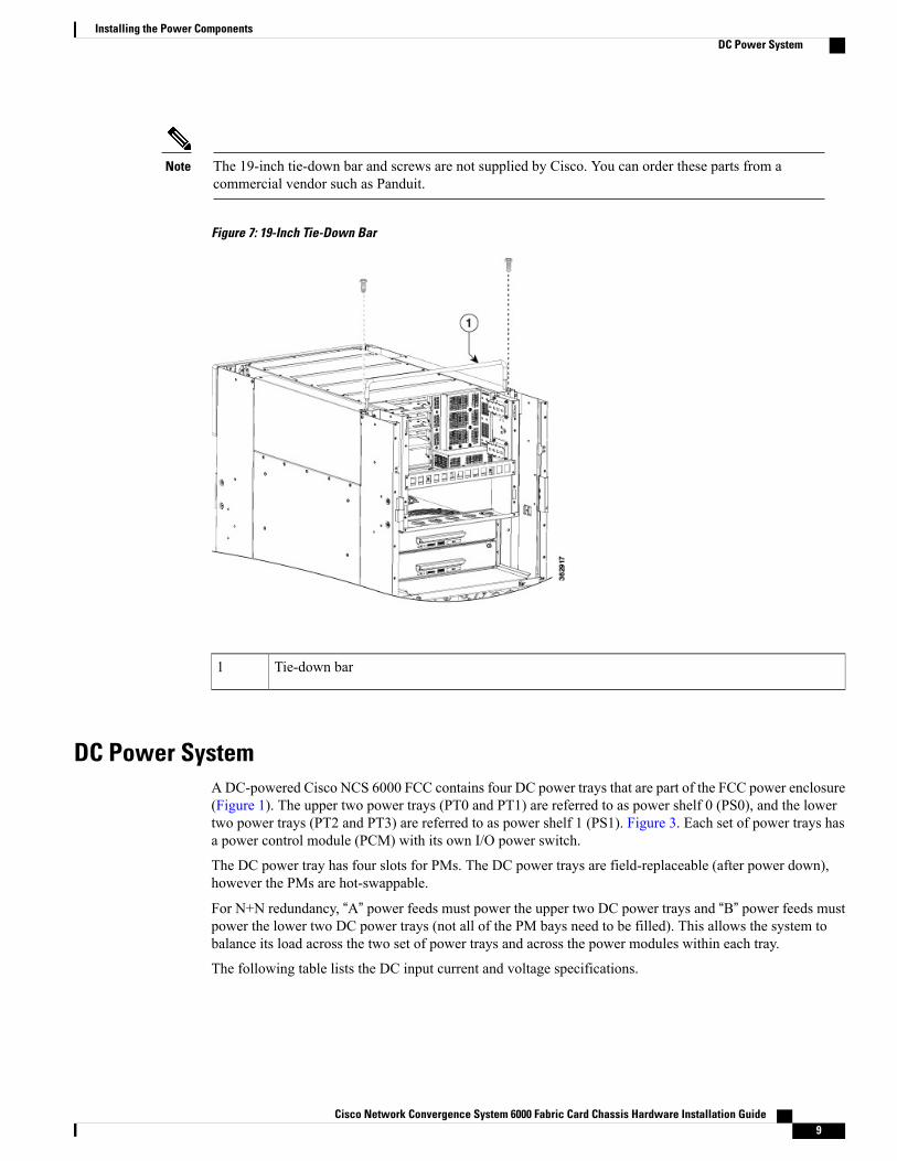
The 19-inch tie-down bar and screws are not supplied by Cisco. You can order these parts from acommercial vendor such as Panduit.
Note
Figure 7: 19-Inch Tie-Down Bar
Tie-down bar1
DC Power SystemADC-powered Cisco NCS 6000 FCC contains four DC power trays that are part of the FCC power enclosure(Figure 1). The upper two power trays (PT0 and PT1) are referred to as power shelf 0 (PS0), and the lowertwo power trays (PT2 and PT3) are referred to as power shelf 1 (PS1). Figure 3. Each set of power trays hasa power control module (PCM) with its own I/O power switch.
The DC power tray has four slots for PMs. The DC power trays are field-replaceable (after power down),however the PMs are hot-swappable.
For N+N redundancy, “A” power feeds must power the upper two DC power trays and “B” power feeds mustpower the lower two DC power trays (not all of the PM bays need to be filled). This allows the system tobalance its load across the two set of power trays and across the power modules within each tray.
The following table lists the DC input current and voltage specifications.
Cisco Network Convergence System 6000 Fabric Card Chassis Hardware Installation Guide 9
Installing the Power ComponentsDC Power System
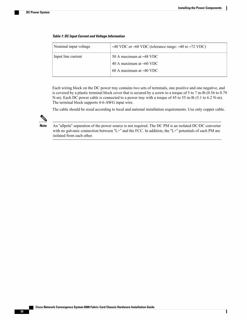
Table 1: DC Input Current and Voltage Information
–48 VDC or –60 VDC (tolerance range: –40 to –72 VDC)Nominal input voltage
50 A maximum at –48 VDC40 A maximum at –60 VDC60 A maximum at –40 VDC
Input line current
Each wiring block on the DC power tray contains two sets of terminals, one positive and one negative, andis covered by a plastic terminal block cover that is secured by a screw to a torque of 5 to 7 in-lb (0.56 to 0.79N-m). Each DC power cable is connected to a power tray with a torque of 45 to 55 in-lb (5.1 to 6.2 N-m).The terminal block supports 4-6-AWG input wire.
The cable should be sized according to local and national installation requirements. Use only copper cable.
An “allpole” separation of the power source is not required. The DC PM is an isolated DC/DC converterwith no galvanic connection between “L+” and the FCC. In addition, the “L+” potentials of each PM areisolated from each other.
Note
Cisco Network Convergence System 6000 Fabric Card Chassis Hardware Installation Guide10
Installing the Power ComponentsDC Power System
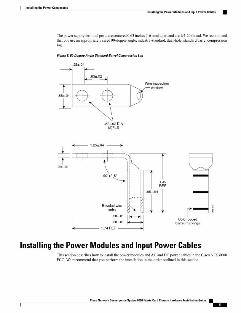
The power supply terminal posts are centered 0.63 inches (16 mm) apart and are 1/4-20 thread.We recommendthat you use an appropriately sized 90-degree angle, industry-standard, dual-hole, standard barrel compressionlug.
Figure 8: 90-Degree Angle Standard Barrel Compression Lug
Installing the Power Modules and Input Power CablesThis section describes how to install the power modules and AC and DC power cables in the Cisco NCS 6000FCC. We recommend that you perform the installation in the order outlined in this section.
Cisco Network Convergence System 6000 Fabric Card Chassis Hardware Installation Guide 11
Installing the Power ComponentsInstalling the Power Modules and Input Power Cables
Ensure that the ground cable is installed on the FCC before you install the power modules and input powercables. See the Installing the Fabric Card Chassis Ground Cable, on page 1.
Note
Installing an AC or DC Power ModuleThis section describes how to install an AC or DC power module (PM) into the power trays in the Cisco NCS6000 FCC. Although there are differences between the AC and DC PMs, they are installed by using the sameprocedures.
An AC-powered FCC supports up to 12 AC PMs (three per power tray). A DC-powered FCC supportsup to 16 DC PM (four per power tray).
Note
Cisco Network Convergence System 6000 Fabric Card Chassis Hardware Installation Guide12
Installing the Power ComponentsInstalling an AC or DC Power Module
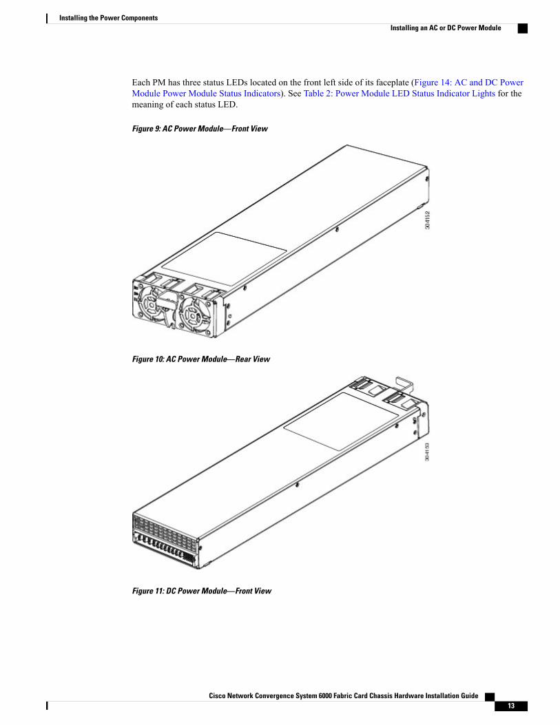
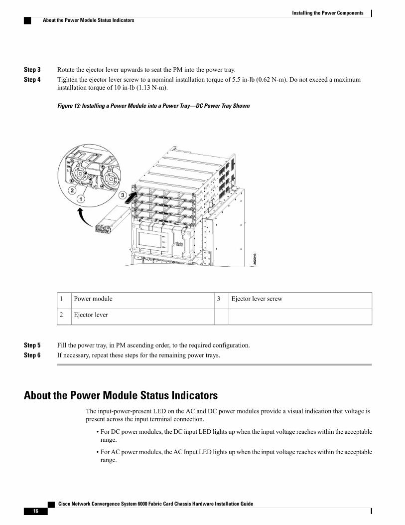
Each PM has three status LEDs located on the front left side of its faceplate (Figure 14: AC and DC PowerModule Power Module Status Indicators). See Table 2: Power Module LED Status Indicator Lights for themeaning of each status LED.
Figure 9: AC Power Module—Front View
Figure 10: AC Power Module—Rear View
Figure 11: DC Power Module—Front View
Cisco Network Convergence System 6000 Fabric Card Chassis Hardware Installation Guide 13
Installing the Power ComponentsInstalling an AC or DC Power Module
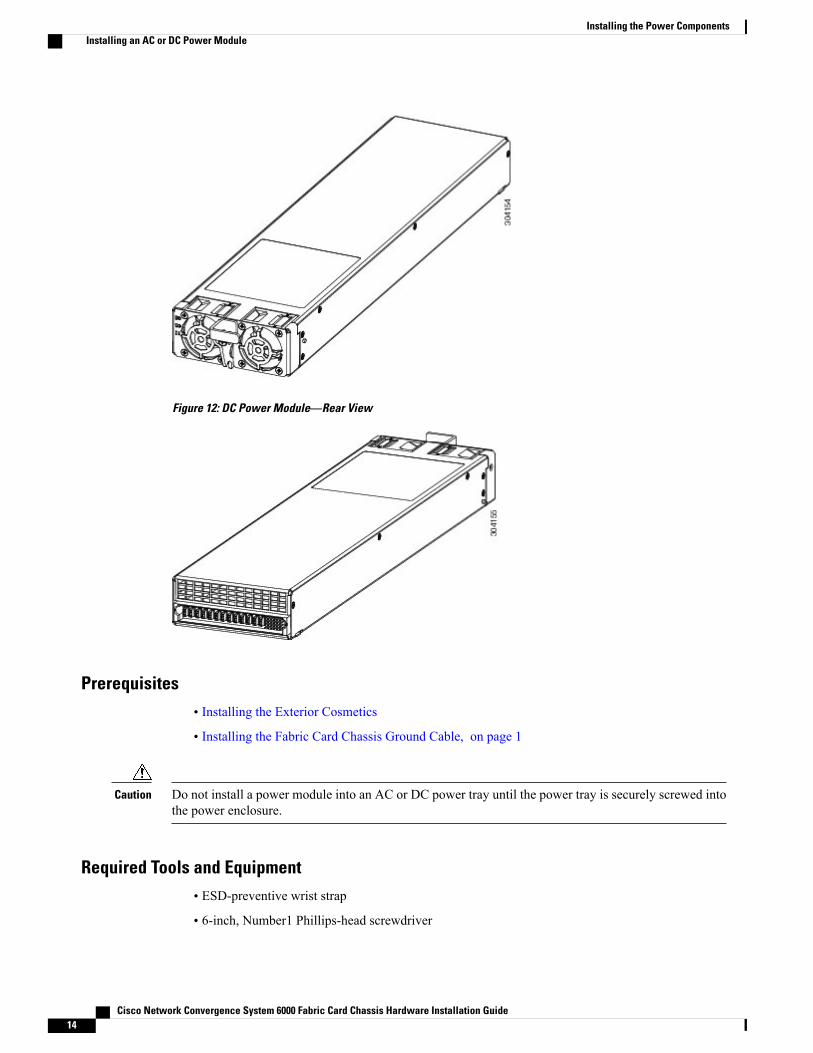
Figure 12: DC Power Module—Rear View
Prerequisites• Installing the Exterior Cosmetics
• Installing the Fabric Card Chassis Ground Cable, on page 1
Do not install a power module into an AC or DC power tray until the power tray is securely screwed intothe power enclosure.
Caution
Required Tools and Equipment• ESD-preventive wrist strap
• 6-inch, Number1 Phillips-head screwdriver
Cisco Network Convergence System 6000 Fabric Card Chassis Hardware Installation Guide14
Installing the Power ComponentsInstalling an AC or DC Power Module
• Torque screwdriver with Number-1 Phillips bit and rated torque at 5.5 in-lb (0.62 N-m)
• AC or DC PM
◦AC PM (Cisco PID PWR-3KW-AC-V2)
◦DC PM (Cisco PID PWR-2KW-DC-V2)
Steps
Power modules are keyed to prevent incorrect insertion into the power tray.Note
To install a PM into a power tray, follow these steps:
Step 1 Attach the ESD-preventive wrist strap to your wrist and connect its leash to the ESD jack on the front side of the FCC(see Preventing Electrostatic Discharge). You can also connect the ESD-preventive wrist strap leash to any bare metalsurface on the FCC.
Step 2 Use two hands to support and guide the PM, and then slide it into the power tray.Though a PM can be inserted into any empty PM bay in any power tray, during the initial installation, install aPM into PM0 in PT0 first. Next, install PMs in ascending order into the remaining PM bays in PT0. Then, installPMs in ascending order into the remaining power trays.
Note
Cisco Network Convergence System 6000 Fabric Card Chassis Hardware Installation Guide 15
Installing the Power ComponentsInstalling an AC or DC Power Module
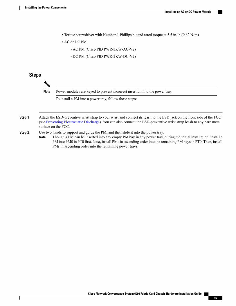
Step 3 Rotate the ejector lever upwards to seat the PM into the power tray.Step 4 Tighten the ejector lever screw to a nominal installation torque of 5.5 in-lb (0.62 N-m). Do not exceed a maximum
installation torque of 10 in-lb (1.13 N-m).
Figure 13: Installing a Power Module into a Power Tray—DC Power Tray Shown
Ejector lever screw3Power module1
Ejector lever2
Step 5 Fill the power tray, in PM ascending order, to the required configuration.Step 6 If necessary, repeat these steps for the remaining power trays.
About the Power Module Status IndicatorsThe input-power-present LED on the AC and DC power modules provide a visual indication that voltage ispresent across the input terminal connection.
• For DC power modules, the DC input LED lights up when the input voltage reaches within the acceptablerange.
• For AC power modules, the AC Input LED lights up when the input voltage reaches within the acceptablerange.
Cisco Network Convergence System 6000 Fabric Card Chassis Hardware Installation Guide16
Installing the Power ComponentsAbout the Power Module Status Indicators
Always disconnect power servicing the input power connection.Note
If the input voltage polarity is reversed, or if the LED circuit fails, the LED will not light. In this case,service personnel should check for hazardous voltages before working on the system.
Caution
Figure 14: AC and DC Power Module Power Module Status Indicators
Fault LED3Input OK LED1
Output OK LED2
Cisco Network Convergence System 6000 Fabric Card Chassis Hardware Installation Guide 17
Installing the Power ComponentsAbout the Power Module Status Indicators

Table 2: Power Module LED Status Indicator Lights
MeaningColorLED Name
On: The input voltage is present and within regulation range.
Blinking: The input voltage is present but out of regulation range.
Off: The input voltage is not present.
GreenInput OK
On: The output voltage is on.
Blinking: The PM is in a power limit or Over Current condition.
Off: The output voltage is off.
GreenOutput OK
On: An internal fault is detected within the PM.
Off: No internal faults detected on the PM.
RedFault
Installing an AC or DC Power Module Slot CoverThis section describes how to install a PM slot cover into an empty PM slot on an AC or DC power tray.
PrerequisitesBefore performing this task, you must remove the cosmetic grilles and install the PMs to the requiredconfiguration in each power tray.
Required Tools and Equipment• ESD-preventive wrist strap
• AC or DC PM slot cover (Cisco PID A9K-PEM-V2-FILR)
Cisco Network Convergence System 6000 Fabric Card Chassis Hardware Installation Guide18
Installing the Power ComponentsInstalling an AC or DC Power Module Slot Cover
StepsTo install a PM slot cover in an AC or DC power tray, follow these steps:
Step 1 Attach the ESD-preventive wrist strap to your wrist and connect its leash to the ESD jack on the front side of the FCC(see Preventing Electrostatic Discharge). You can also connect the ESD-preventive wrist strap leash to any bare metalsurface on the FCC.
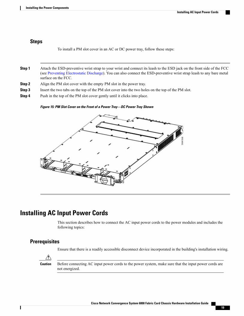
Step 2 Align the PM slot cover with the empty PM slot in the power tray.Step 3 Insert the two tabs on the top of the PM slot cover into the two holes on the top of the PM slot.Step 4 Push in the top of the PM slot cover gently until it clicks into place.
Figure 15: PM Slot Cover on the Front of a Power Tray—DC Power Tray Shown
Installing AC Input Power CordsThis section describes how to connect the AC input power cords to the power modules and includes thefollowing topics:
PrerequisitesEnsure that there is a readily accessible disconnect device incorporated in the building's installation wiring.
Before connecting AC input power cords to the power system, make sure that the input power cords arenot energized.
Caution
Cisco Network Convergence System 6000 Fabric Card Chassis Hardware Installation Guide 19
Installing the Power ComponentsInstalling AC Input Power Cords
The circuit breaker and fuse lockout procedures should follow the rules and regulations in the NationalElectrical Code (NEC) and any local codes.
Caution
The AC power system requires single-phase AC input power to each PM. If you have 3-phase AC Deltaor AC Wye at your equipment, a Cisco NCS 6000 Series power distribution unit (PDU) is required toconvert 3-phase AC input power to single-phase AC input power (Cisco PID NCS-PDU-DELTA or CiscoPID NCS-PDU-WYE). For more information, see the Cisco CRS 3-Phase AC Power Distribution UnitInstallation Guide.
Note
Required Tools and Equipment• 6-inch, Number 1 Phillips-head screwdriver
• AC input power cords, depending on the locale (Appendix B, “System Product IDs.”)
StepsTo install the AC input power cords, follow these steps:
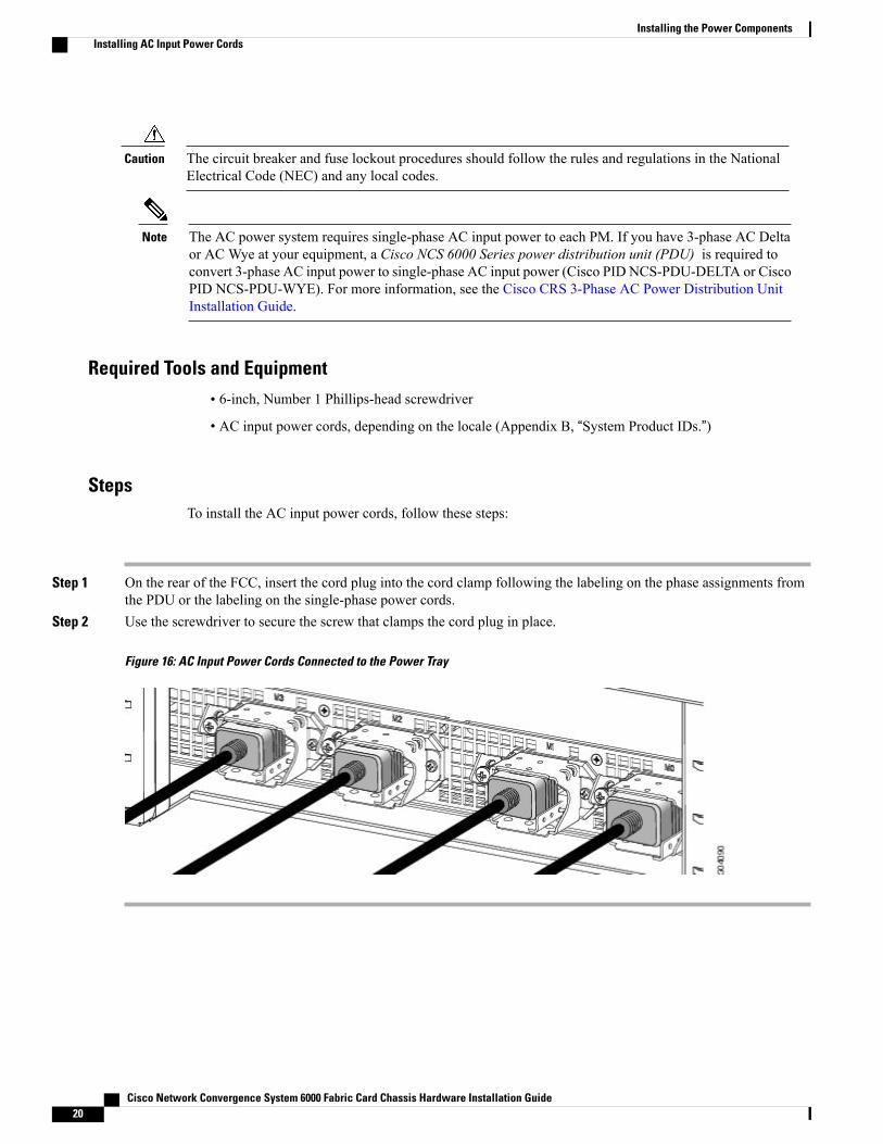
Step 1 On the rear of the FCC, insert the cord plug into the cord clamp following the labeling on the phase assignments fromthe PDU or the labeling on the single-phase power cords.
Step 2 Use the screwdriver to secure the screw that clamps the cord plug in place.
Figure 16: AC Input Power Cords Connected to the Power Tray
Cisco Network Convergence System 6000 Fabric Card Chassis Hardware Installation Guide20
Installing the Power ComponentsInstalling AC Input Power Cords
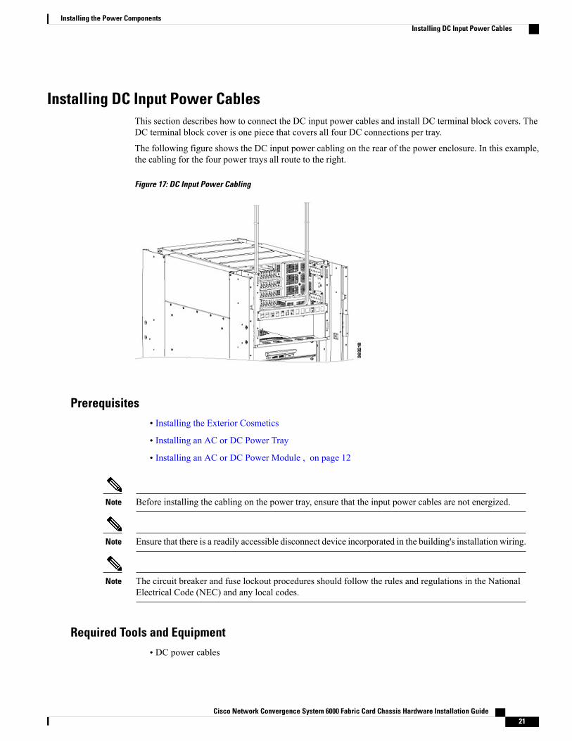
Installing DC Input Power CablesThis section describes how to connect the DC input power cables and install DC terminal block covers. TheDC terminal block cover is one piece that covers all four DC connections per tray.
The following figure shows the DC input power cabling on the rear of the power enclosure. In this example,the cabling for the four power trays all route to the right.
Figure 17: DC Input Power Cabling
Prerequisites• Installing the Exterior Cosmetics
• Installing an AC or DC Power Tray
• Installing an AC or DC Power Module , on page 12
Before installing the cabling on the power tray, ensure that the input power cables are not energized.Note
Ensure that there is a readily accessible disconnect device incorporated in the building's installation wiring.Note
The circuit breaker and fuse lockout procedures should follow the rules and regulations in the NationalElectrical Code (NEC) and any local codes.
Note
Required Tools and Equipment• DC power cables
Cisco Network Convergence System 6000 Fabric Card Chassis Hardware Installation Guide 21
Installing the Power ComponentsInstalling DC Input Power Cables
• DC power cable lugs
• Crimping tool and lug-specific die
• 3/8-inch ratchet wrench with 7/16-pt. socket
• Multimeter
• Torque wrench with torque value rated up to 55 in-lb (6.2 N-m)
• Terminal block cover
• Torque screwdriver with Number-1 Phillips 8-inch shank, and a torque rating of 5 to 7 in-lb (0.56 to0.79 N-m)
StepsTo connect the DC input power cables, follow these steps:
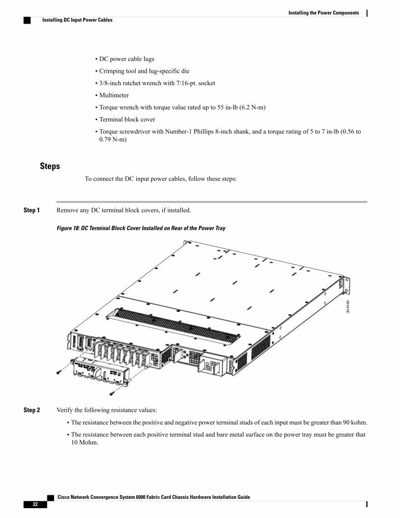
Step 1 Remove any DC terminal block covers, if installed.
Figure 18: DC Terminal Block Cover Installed on Rear of the Power Tray
Step 2 Verify the following resistance values:
• The resistance between the positive and negative power terminal studs of each input must be greater than 90 kohm.
• The resistance between each positive terminal stud and bare metal surface on the power tray must be greater that10 Mohm.
Cisco Network Convergence System 6000 Fabric Card Chassis Hardware Installation Guide22
Installing the Power ComponentsInstalling DC Input Power Cables
• The resistance between each negative terminal stud and bare metal surface on the power tray must be greater that10 Mohm.
Typical hand held ohmmeters will not measure 10Mohm; instead they will auto-range to acquire a measurementand give an out-of-range reading. This is an acceptable reading provided that the meter is in calibration.
Note
Step 3 Use the crimping tool mandated by the lug manufacturer to crimp the lugs to the DC input cables. For details on lugs,see the DC Power System, on page 9.The cable should be sized according to local and national installation requirements. Use only copper cable.
The power supply terminal block lug width is 0.60 inches (1.50 cm). The terminal posts are centered 0.63 inches(16 mm) apart and are 1/4-20 thread. We recommend that you use an appropriately sized 90-degree,industry-standard, dual-hole, standard barrel compression lug.
Note
Step 4 Using the wrench, attach the positive and negative cable pairs to each terminal block on the power tray (PT0). Start withPM0 (located on the right side) and move left, finishing with PM3 (located on the left side). Use the torque wrench totighten to a torque of 45 to 55 in-lb (5.1 to 6.2 N-m).
Make sure that the polarity of the DC input power cabling is correct. This is a negative voltage system.Caution
This is a positive ground system; make sure to connect the positive lead to the +RTN terminal and the negativelead to the –48V terminal.
Caution
Step 5 Align the DC terminal block cover with the cover latch tab.Step 6 Slide the terminal block cover upwards to align the screw with the mounting standoff.Step 7 Use the screwdriver to secure the screw into the mounting standoff and tighten to a torque of 5 to 7 in-lb (0.56 to 0.79
N-m).Step 8 Repeat these steps for all the power trays.
Powering On and Powering Off the Fabric Card ChassisThis section describes how to power on and power off an AC-powered or DC-powered Cisco NCS 6000 FCC.
Powering On the Fabric Card Chassis
Prerequisites• Installing an AC or DC Power Module , on page 12
• Installing an AC or DC Power Module Slot Cover , on page 18
• Installing AC Input Power Cords, on page 19
• Installing DC Input Power Cables , on page 21
Ensure that the FCC is properly grounded (see the Installing the Fabric Card Chassis Ground Cable, on page1 section).
If you have a DC power system installed, the wiring at the Battery Distribution Fuse Bay (BDFB) or at thepower plant must be complete.
Cisco Network Convergence System 6000 Fabric Card Chassis Hardware Installation Guide 23
Installing the Power ComponentsPowering On and Powering Off the Fabric Card Chassis
Required Tools and Equipment• Voltmeter
StepsTo power on the FCC, follow these steps:
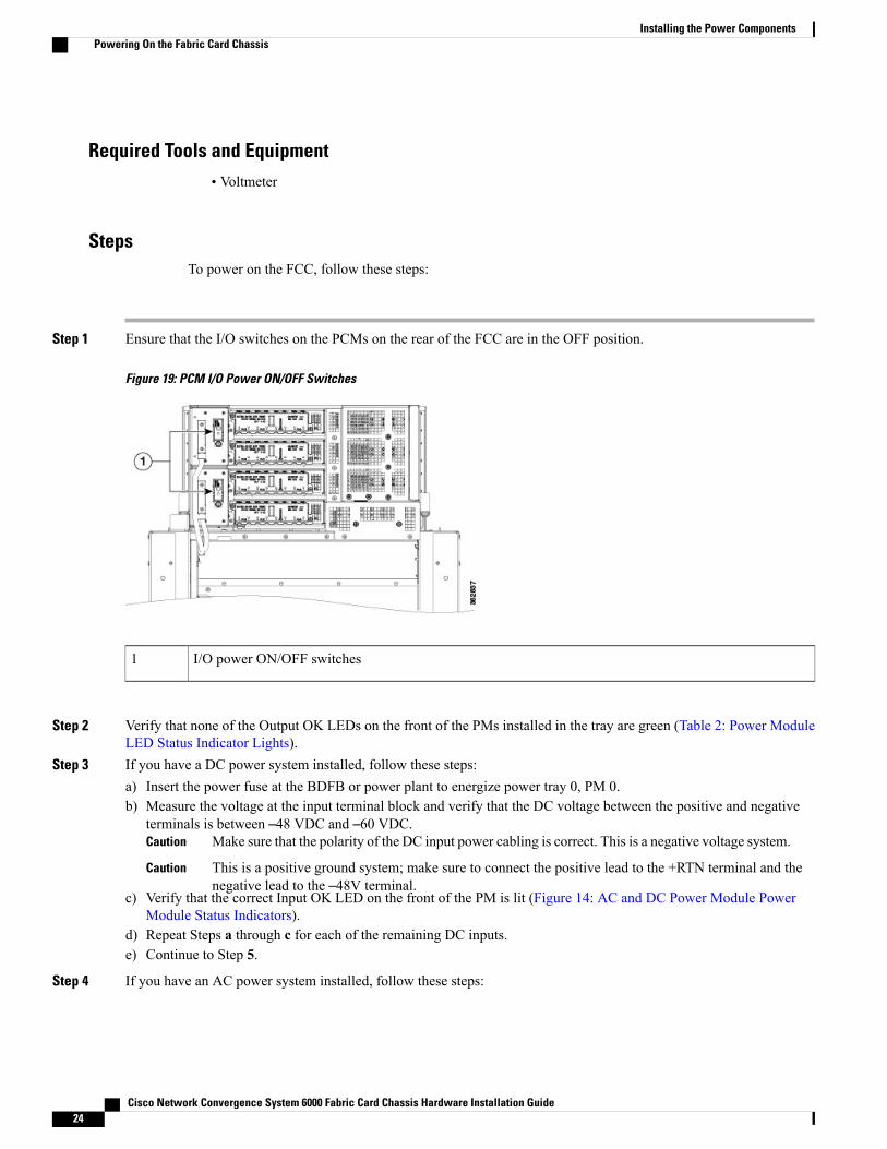
Step 1 Ensure that the I/O switches on the PCMs on the rear of the FCC are in the OFF position.
Figure 19: PCM I/O Power ON/OFF Switches
I/O power ON/OFF switches1
Step 2 Verify that none of the Output OK LEDs on the front of the PMs installed in the tray are green (Table 2: Power ModuleLED Status Indicator Lights).
Step 3 If you have a DC power system installed, follow these steps:a) Insert the power fuse at the BDFB or power plant to energize power tray 0, PM 0.b) Measure the voltage at the input terminal block and verify that the DC voltage between the positive and negative
terminals is between –48 VDC and –60 VDC.Make sure that the polarity of the DC input power cabling is correct. This is a negative voltage system.Caution
This is a positive ground system; make sure to connect the positive lead to the +RTN terminal and thenegative lead to the –48V terminal.
Caution
c) Verify that the correct Input OK LED on the front of the PM is lit (Figure 14: AC and DC Power Module PowerModule Status Indicators).
d) Repeat Steps a through c for each of the remaining DC inputs.e) Continue to Step 5.
Step 4 If you have an AC power system installed, follow these steps:
Cisco Network Convergence System 6000 Fabric Card Chassis Hardware Installation Guide24
Installing the Power ComponentsPowering On the Fabric Card Chassis
a) For the individual single-phase input, open the individual circuit breaker for each PM installed at the circuit breakercabinet.
b) Energize the individual single-phase breaker at the circuit breaker panel one at a time and verify that the Input OKLED is lit on the front of the PM that is energized. Continue to Step 5.
c) For AC PDU; Ensure that the PDU circuit breakers are in the open positiond) Plug in the 3-phase commando plug for the first three-phase circuit into the source three-phase plug.e) Close PM0 (AB) on the PDU and verify that the Input OK LED is lit on the front of the PM that is energized and
that the correct input LED lights.f) Repeat Steps c through e for the remaining PMs.
Step 5 Turn the I/O switches on the PCMs to the ON position, and verify that the output LED is on (Figure 19: PCM I/O PowerON/OFF Switches ).
Step 6 Verify that the fan tray status LEDs are lit and that the fans are running.Step 7 Turn off the rear power breakers for power trays (FT0) and power trays (FT1).
If the fault LED on any of the PMs are lit, we recommend that you replace the PM (see the Component ProductIDs for the Cisco PID). If the problem continues, please contact your Cisco support representative for assistance.
Note
Step 8 Install all cards in the FCC. For installation information, see Installing the Shelf Controller Cards and Fabric CardsStep 9 Turn on the output breakers when finished.
Powering Off the Fabric Card ChassisThis section describes how to power off an AC-powered or DC-powered Cisco NCS 6000 FCC.
StepsTo power off the FCC follow these steps:
Step 1 Turn the I/O switches on the PCMs to the OFF position (Figure 19: PCM I/O Power ON/OFF Switches ).Step 2 If you have a DC power system installed, remove the power fuse at the BDFB or power plant for each PM on all power
trays.Step 3 If you have an AC power system installed, turn off the source circuit breakers to de-energize the PMs in all the power
trays.Step 4 Verify that all PM input LEDs are off (Figure 14: AC and DC Power Module Power Module Status Indicators).
All DC power cables or AC power cords must be de-energized to fully remove power from the FCC.Note
Cisco Network Convergence System 6000 Fabric Card Chassis Hardware Installation Guide 25
Installing the Power ComponentsPowering Off the Fabric Card Chassis

Cisco Network Convergence System 6000 Fabric Card Chassis Hardware Installation Guide26
Installing the Power ComponentsPowering Off the Fabric Card Chassis