installing fieldbus.pmd - chemical processing
TRANSCRIPT
Installing Fieldbus
Installing Fieldbus
Many automation engineers are coming face to facewith real fieldbus applications for the first time.Fieldbus (the use of digital communications networksfor distributed instrumentation and control) is awonderful technology with many benefits, but fieldbusinstallation requires some additional considerationsover and above normal 4-20mA projects. In this article,we will discuss some of those issues, and show youhow to deal with them.
Choosing a “Fieldbus”Don’t get hung up on which fieldbus to choose.Fieldbus is a generic term for a variety ofcommunications protocols using various media, but allare simply a means to an end. What you want at theend of the project is a satisfactory and functionalcontrol system, and practically every installationwill use multiple fieldbuses to accomplish the manytasks required. For example, you may useFOUNDATION™ fieldbus in the process plant, DeviceNetfor a PLC network, and PROFIdrive to run motor drives.Every DCS can easily integrate all these functionalplant buses into the Ethernet-based control room bus.
In process control engineering, “fieldbus” normallymeans FOUNDATION fieldbus H1 (H1) or PROFIBUSPA (PA); both fieldbuses are perfectly adequate andwidely used around the world in refineries and processplants as modern day enhancements to 4-20mA, 2-wiredevices. This article focuses on H1 and PA physicallayer implementation.
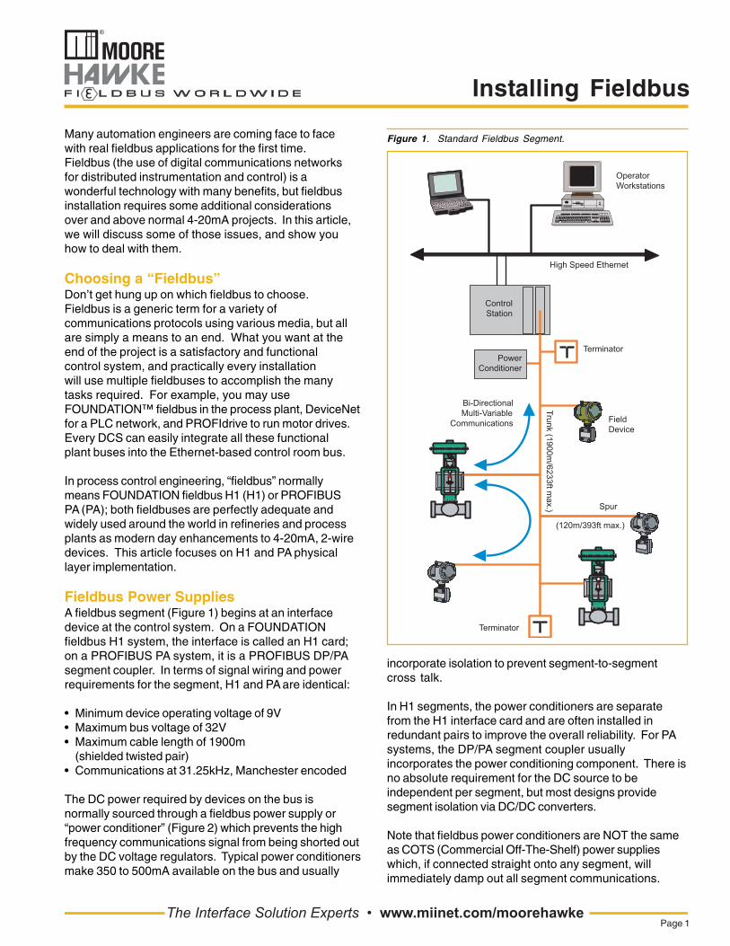
Fieldbus Power SuppliesA fieldbus segment (Figure 1) begins at an interfacedevice at the control system. On a FOUNDATIONfieldbus H1 system, the interface is called an H1 card;on a PROFIBUS PA system, it is a PROFIBUS DP/PAsegment coupler. In terms of signal wiring and powerrequirements for the segment, H1 and PA are identical:
• Minimum device operating voltage of 9V• Maximum bus voltage of 32V• Maximum cable length of 1900m
(shielded twisted pair)• Communications at 31.25kHz, Manchester encoded
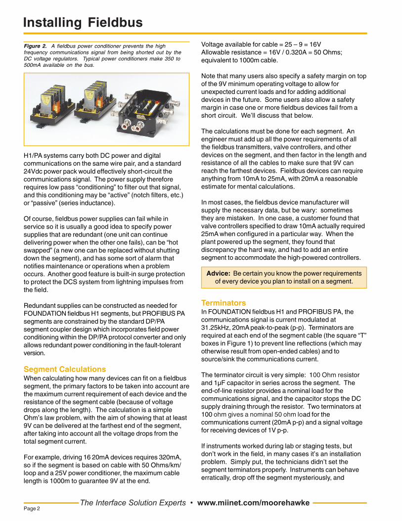
The DC power required by devices on the bus isnormally sourced through a fieldbus power supply or“power conditioner” (Figure 2) which prevents the highfrequency communications signal from being shorted outby the DC voltage regulators. Typical power conditionersmake 350 to 500mA available on the bus and usually
The Interface Solution Experts • www.miinet.com/moorehawkePage 1
Trunk (1900m/6233ft m
ax.)
(120m/393ft max.)
incorporate isolation to prevent segment-to-segmentcross talk.
In H1 segments, the power conditioners are separatefrom the H1 interface card and are often installed inredundant pairs to improve the overall reliability. For PAsystems, the DP/PA segment coupler usuallyincorporates the power conditioning component. There isno absolute requirement for the DC source to beindependent per segment, but most designs providesegment isolation via DC/DC converters.
Note that fieldbus power conditioners are NOT the sameas COTS (Commercial Off-The-Shelf) power supplieswhich, if connected straight onto any segment, willimmediately damp out all segment communications.
Figure 1. Standard Fieldbus Segment.
Installing Fieldbus
H1/PA systems carry both DC power and digitalcommunications on the same wire pair, and a standard24Vdc power pack would effectively short-circuit thecommunications signal. The power supply thereforerequires low pass “conditioning” to filter out that signal,and this conditioning may be “active” (notch filters, etc.)or “passive” (series inductance).
Of course, fieldbus power supplies can fail while inservice so it is usually a good idea to specify powersupplies that are redundant (one unit can continuedelivering power when the other one fails), can be “hotswapped” (a new one can be replaced without shuttingdown the segment), and has some sort of alarm thatnotifies maintenance or operations when a problemoccurs. Another good feature is built-in surge protectionto protect the DCS system from lightning impulses fromthe field.
Redundant supplies can be constructed as needed forFOUNDATION fieldbus H1 segments, but PROFIBUS PAsegments are constrained by the standard DP/PAsegment coupler design which incorporates field powerconditioning within the DP/PA protocol converter and onlyallows redundant power conditioning in the fault-tolerantversion.
Segment CalculationsWhen calculating how many devices can fit on a fieldbussegment, the primary factors to be taken into account arethe maximum current requirement of each device and theresistance of the segment cable (because of voltagedrops along the length). The calculation is a simpleOhm’s law problem, with the aim of showing that at least9V can be delivered at the farthest end of the segment,after taking into account all the voltage drops from thetotal segment current.
For example, driving 16 20mA devices requires 320mA,so if the segment is based on cable with 50 Ohms/km/loop and a 25V power conditioner, the maximum cablelength is 1000m to guarantee 9V at the end.
Figure 2. A fieldbus power conditioner prevents the highfrequency communications signal from being shorted out by theDC voltage regulators. Typical power conditioners make 350 to500mA available on the bus.
The Interface Solution Experts • www.miinet.com/moorehawkePage 2
Voltage available for cable = 25 – 9 = 16VAllowable resistance = 16V / 0.320A = 50 Ohms;equivalent to 1000m cable.
Note that many users also specify a safety margin on topof the 9V minimum operating voltage to allow forunexpected current loads and for adding additionaldevices in the future. Some users also allow a safetymargin in case one or more fieldbus devices fail from ashort circuit. We’ll discuss that below.
The calculations must be done for each segment. Anengineer must add up all the power requirements of allthe fieldbus transmitters, valve controllers, and otherdevices on the segment, and then factor in the length andresistance of all the cables to make sure that 9V canreach the farthest devices. Fieldbus devices can requireanything from 10mA to 25mA, with 20mA a reasonableestimate for mental calculations.
In most cases, the fieldbus device manufacturer willsupply the necessary data, but be wary: sometimesthey are mistaken. In one case, a customer found thatvalve controllers specified to draw 10mA actually required25mA when configured in a particular way. When theplant powered up the segment, they found thatdiscrepancy the hard way, and had to add an entiresegment to accommodate the high-powered controllers.
Advice: Be certain you know the power requirementsof every device you plan to install on a segment.
TerminatorsIn FOUNDATION fieldbus H1 and PROFIBUS PA, thecommunications signal is current modulated at31.25kHz, 20mA peak-to-peak (p-p). Terminators arerequired at each end of the segment cable (the square “T”boxes in Figure 1) to prevent line reflections (which mayotherwise result from open-ended cables) and tosource/sink the communications current.
The terminator circuit is very simple: 100 Ohm resistorand 1µF capacitor in series across the segment. Theend-of-line resistor provides a nominal load for thecommunications signal, and the capacitor stops the DCsupply draining through the resistor. Two terminators at100 ohm gives a nominal 50 ohm load for thecommunications current (20mA p-p) and a signal voltagefor receiving devices of 1V p-p.
If instruments worked during lab or staging tests, butdon’t work in the field, in many cases it’s an installationproblem. Simply put, the technicians didn’t set thesegment terminators properly. Instruments can behaveerratically, drop off the segment mysteriously, and
Installing Fieldbus
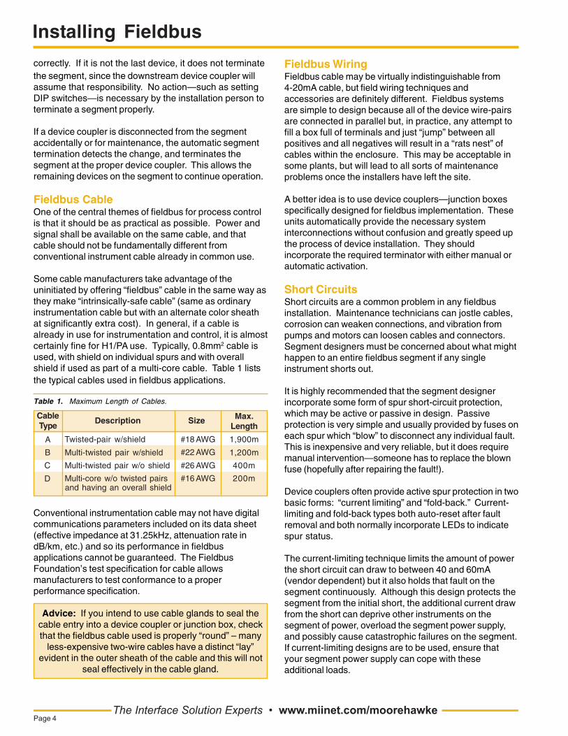
Figure 4. Terminators (shown as square T boxes) must be turnedon at the beginning and at the end of each segment.
T
Fieldbus DCPower Conditioner,350-500mA(Not Required for PA Systems)
T
DC Power Input
FieldbusTermination
FOUNDATION fieldbus or PROFIBUS PA Network (Twisted Wire Pair)
AutomaticSegment
Termination
FieldbusDevices
FieldbusTrunk
Out
TG200 FieldbusDevice Coupler
TG200 FieldbusDevice Coupler
FieldbusTrunk In
FieldbusTrunk Out
FieldbusTrunk In
"Fold-Back"Short Circuit Protectionwith Auto Reset
H1/PA Interface
generally raise havoc—all because the terminations arenot set properly.
Two terminators are required per segment, one at eachend. With one terminator, the signal will be higher, andwith three or four terminators, the signal will be lower.Many field devices won’t accept signals at 2V p-p andmay unexpectedly reset. With three or four terminators,the signal can be so low it is unusable. The absoluteminimum signal that devices must be able to recognizeis 150mV p-p.
Some users may test a segment in a lab, or at thevendor site. In such a case, under carefully controlledconditions, the segment may actually work with incorrectterminators. However, they rarely work in the field whennot terminated properly.
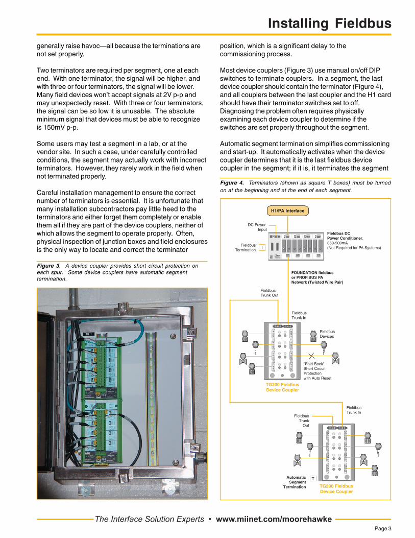
Careful installation management to ensure the correctnumber of terminators is essential. It is unfortunate thatmany installation subcontractors pay little heed to theterminators and either forget them completely or enablethem all if they are part of the device couplers, neither ofwhich allows the segment to operate properly. Often,physical inspection of junction boxes and field enclosuresis the only way to locate and correct the terminator
Figure 3. A device coupler provides short circuit protection oneach spur. Some device couplers have automatic segmenttermination.
position, which is a significant delay to thecommissioning process.
Most device couplers (Figure 3) use manual on/off DIPswitches to terminate couplers. In a segment, the lastdevice coupler should contain the terminator (Figure 4),and all couplers between the last coupler and the H1 cardshould have their terminator switches set to off.Diagnosing the problem often requires physicallyexamining each device coupler to determine if theswitches are set properly throughout the segment.
Automatic segment termination simplifies commissioningand start-up. It automatically activates when the devicecoupler determines that it is the last fieldbus devicecoupler in the segment; if it is, it terminates the segment
The Interface Solution Experts • www.miinet.com/moorehawkePage 3
Installing Fieldbus
the segment, since the downstream device coupler willassume that responsibility. No action—such as settingDIP switches—is necessary by the installation person toterminate a segment properly.
If a device coupler is disconnected from the segmentaccidentally or for maintenance, the automatic segmenttermination detects the change, and terminates thesegment at the proper device coupler. This allows theremaining devices on the segment to continue operation.
Fieldbus CableOne of the central themes of fieldbus for process controlis that it should be as practical as possible. Power andsignal shall be available on the same cable, and thatcable should not be fundamentally different fromconventional instrument cable already in common use.
Some cable manufacturers take advantage of theuninitiated by offering “fieldbus” cable in the same way asthey make “intrinsically-safe cable” (same as ordinaryinstrumentation cable but with an alternate color sheathat significantly extra cost). In general, if a cable isalready in use for instrumentation and control, it is almostcertainly fine for H1/PA use. Typically, 0.8mm2 cable isused, with shield on individual spurs and with overallshield if used as part of a multi-core cable. Table 1 liststhe typical cables used in fieldbus applications.
Conventional instrumentation cable may not have digitalcommunications parameters included on its data sheet(effective impedance at 31.25kHz, attenuation rate indB/km, etc.) and so its performance in fieldbusapplications cannot be guaranteed. The FieldbusFoundation’s test specification for cable allowsmanufacturers to test conformance to a properperformance specification.
Advice: If you intend to use cable glands to seal thecable entry into a device coupler or junction box, checkthat the fieldbus cable used is properly “round” – many
less-expensive two-wire cables have a distinct “lay”evident in the outer sheath of the cable and this will not
seal effectively in the cable gland.
Table 1. Maximum Length of Cables.
CableType
Max.Length
Description Size
A
B
C
D
#18 AWG
#22 AWG
#26 AWG
#16 AWG
1,900m
1,200m
400m
200m
Twisted-pair w/shield
Multi-twisted pair w/shield
Multi-twisted pair w/o shield
Multi-core w/o twisted pairsand having an overall shield
The Interface Solution Experts • www.miinet.com/moorehawkePage 4
Fieldbus WiringFieldbus cable may be virtually indistinguishable from4-20mA cable, but field wiring techniques andaccessories are definitely different. Fieldbus systemsare simple to design because all of the device wire-pairsare connected in parallel but, in practice, any attempt tofill a box full of terminals and just “jump” between allpositives and all negatives will result in a “rats nest” ofcables within the enclosure. This may be acceptable insome plants, but will lead to all sorts of maintenanceproblems once the installers have left the site.
A better idea is to use device couplers—junction boxesspecifically designed for fieldbus implementation. Theseunits automatically provide the necessary systeminterconnections without confusion and greatly speed upthe process of device installation. They shouldincorporate the required terminator with either manual orautomatic activation.
Short CircuitsShort circuits are a common problem in any fieldbusinstallation. Maintenance technicians can jostle cables,corrosion can weaken connections, and vibration frompumps and motors can loosen cables and connectors.Segment designers must be concerned about what mighthappen to an entire fieldbus segment if any singleinstrument shorts out.
It is highly recommended that the segment designerincorporate some form of spur short-circuit protection,which may be active or passive in design. Passiveprotection is very simple and usually provided by fuses oneach spur which “blow” to disconnect any individual fault.This is inexpensive and very reliable, but it does requiremanual intervention—someone has to replace the blownfuse (hopefully after repairing the fault!).
Device couplers often provide active spur protection in twobasic forms: “current limiting” and “fold-back.” Current-limiting and fold-back types both auto-reset after faultremoval and both normally incorporate LEDs to indicatespur status.
The current-limiting technique limits the amount of powerthe short circuit can draw to between 40 and 60mA(vendor dependent) but it also holds that fault on thesegment continuously. Although this design protects thesegment from the initial short, the additional current drawfrom the short can deprive other instruments on thesegment of power, overload the segment power supply,and possibly cause catastrophic failures on the segment.If current-limiting designs are to be used, ensure thatyour segment power supply can cope with theseadditional loads.
correctly. If it is not the last device, it does not terminate
Installing Fieldbus
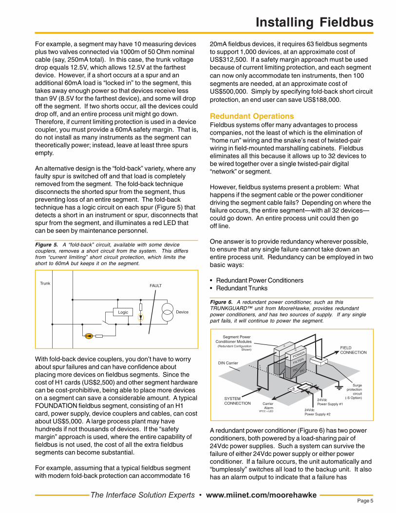
Logic
FAULT
Device
Trunk
For example, a segment may have 10 measuring devicesplus two valves connected via 1000m of 50 Ohm nominalcable (say, 250mA total). In this case, the trunk voltagedrop equals 12.5V, which allows 12.5V at the farthestdevice. However, if a short occurs at a spur and anadditional 60mA load is “locked in” to the segment, thistakes away enough power so that devices receive lessthan 9V (8.5V for the farthest device), and some will dropoff the segment. If two shorts occur, all the devices coulddrop off, and an entire process unit might go down.Therefore, if current limiting protection is used in a devicecoupler, you must provide a 60mA safety margin. That is,do not install as many instruments as the segment cantheoretically power; instead, leave at least three spursempty.
An alternative design is the “fold-back” variety, where anyfaulty spur is switched off and that load is completelyremoved from the segment. The fold-back techniquedisconnects the shorted spur from the segment, thuspreventing loss of an entire segment. The fold-backtechnique has a logic circuit on each spur (Figure 5) thatdetects a short in an instrument or spur, disconnects thatspur from the segment, and illuminates a red LED thatcan be seen by maintenance personnel.
Figure 5. A “fold-back” circuit, available with some devicecouplers, removes a short circuit from the system. This differsfrom “current limiting” short circuit protection, which limits theshort to 60mA but keeps it on the segment.
With fold-back device couplers, you don’t have to worryabout spur failures and can have confidence aboutplacing more devices on fieldbus segments. Since thecost of H1 cards (US$2,500) and other segment hardwarecan be cost-prohibitive, being able to place more deviceson a segment can save a considerable amount. A typicalFOUNDATION fieldbus segment, consisting of an H1card, power supply, device couplers and cables, can costabout US$5,000. A large process plant may havehundreds if not thousands of devices. If the “safetymargin” approach is used, where the entire capability offieldbus is not used, the cost of all the extra fieldbussegments can become substantial.
For example, assuming that a typical fieldbus segmentwith modern fold-back protection can accommodate 16
20mA fieldbus devices, it requires 63 fieldbus segmentsto support 1,000 devices, at an approximate cost ofUS$312,500. If a safety margin approach must be usedbecause of current limiting protection, and each segmentcan now only accommodate ten instruments, then 100segments are needed, at an approximate cost ofUS$500,000. Simply by specifying fold-back short circuitprotection, an end user can save US$188,000.
Redundant OperationsFieldbus systems offer many advantages to processcompanies, not the least of which is the elimination of“home run” wiring and the snake’s nest of twisted-pairwiring in field-mounted marshalling cabinets. Fieldbuseliminates all this because it allows up to 32 devices tobe wired together over a single twisted-pair digital“network” or segment.
However, fieldbus systems present a problem: Whathappens if the segment cable or the power conditionerdriving the segment cable fails? Depending on where thefailure occurs, the entire segment—with all 32 devices—could go down. An entire process unit could then gooff line.
One answer is to provide redundancy wherever possible,to ensure that any single failure cannot take down anentire process unit. Redundancy can be employed in twobasic ways:
• Redundant Power Conditioners• Redundant Trunks
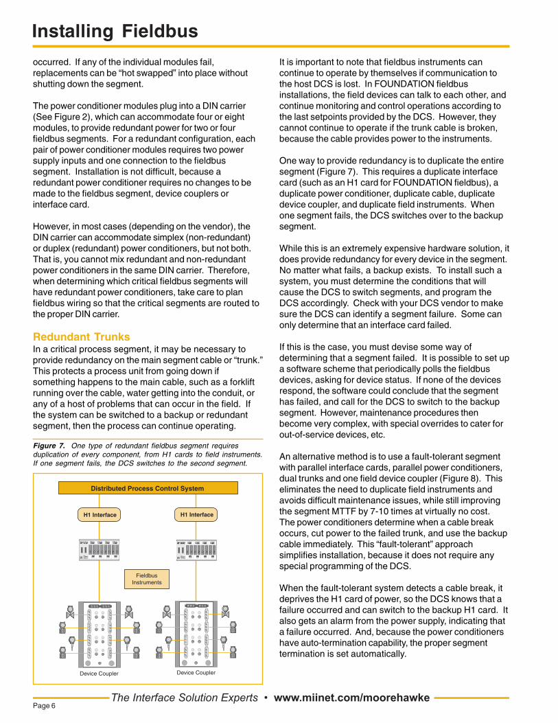
Figure 6. A redundant power conditioner, such as thisTRUNKGUARD™ unit from MooreHawke, provides redundantpower conditioners, and has two sources of supply. If any singlepart fails, it will continue to power the segment.
POWER
FILTER
DCDC
24Vdc Power Supply #1
SYSTEM CONNECTION
FIELDCONNECTION
DIN Carrier
Segment Power Conditioner Modules
Surgeprotection
circuit(-S Option)
24Vdc Power Supply #2
CarrierAlarm
VFCC + LED
(Redundant Configuration Shown)
A redundant power conditioner (Figure 6) has two powerconditioners, both powered by a load-sharing pair of24Vdc power supplies. Such a system can survive thefailure of either 24Vdc power supply or either powerconditioner. If a failure occurs, the unit automatically and“bumplessly” switches all load to the backup unit. It alsohas an alarm output to indicate that a failure has
The Interface Solution Experts • www.miinet.com/moorehawkePage 5
Installing Fieldbus
occurred. If any of the individual modules fail,replacements can be “hot swapped” into place withoutshutting down the segment.
The power conditioner modules plug into a DIN carrier(See Figure 2), which can accommodate four or eightmodules, to provide redundant power for two or fourfieldbus segments. For a redundant configuration, eachpair of power conditioner modules requires two powersupply inputs and one connection to the fieldbussegment. Installation is not difficult, because aredundant power conditioner requires no changes to bemade to the fieldbus segment, device couplers orinterface card.
However, in most cases (depending on the vendor), theDIN carrier can accommodate simplex (non-redundant)or duplex (redundant) power conditioners, but not both.That is, you cannot mix redundant and non-redundantpower conditioners in the same DIN carrier. Therefore,when determining which critical fieldbus segments willhave redundant power conditioners, take care to planfieldbus wiring so that the critical segments are routed tothe proper DIN carrier.
Redundant TrunksIn a critical process segment, it may be necessary toprovide redundancy on the main segment cable or “trunk.”This protects a process unit from going down ifsomething happens to the main cable, such as a forkliftrunning over the cable, water getting into the conduit, orany of a host of problems that can occur in the field. Ifthe system can be switched to a backup or redundantsegment, then the process can continue operating.
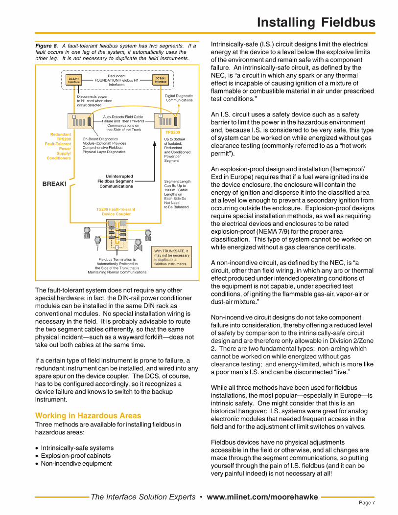
Figure 7. One type of redundant fieldbus segment requiresduplication of every component, from H1 cards to field instruments.If one segment fails, the DCS switches to the second segment.
Device Coupler
FieldbusInstruments
Device Coupler
Distributed Process Control System
The Interface Solution Experts • www.miinet.com/moorehawkePage 6
It is important to note that fieldbus instruments cancontinue to operate by themselves if communication tothe host DCS is lost. In FOUNDATION fieldbusinstallations, the field devices can talk to each other, andcontinue monitoring and control operations according tothe last setpoints provided by the DCS. However, theycannot continue to operate if the trunk cable is broken,because the cable provides power to the instruments.
One way to provide redundancy is to duplicate the entiresegment (Figure 7). This requires a duplicate interfacecard (such as an H1 card for FOUNDATION fieldbus), aduplicate power conditioner, duplicate cable, duplicatedevice coupler, and duplicate field instruments. Whenone segment fails, the DCS switches over to the backupsegment.
While this is an extremely expensive hardware solution, itdoes provide redundancy for every device in the segment.No matter what fails, a backup exists. To install such asystem, you must determine the conditions that willcause the DCS to switch segments, and program theDCS accordingly. Check with your DCS vendor to makesure the DCS can identify a segment failure. Some canonly determine that an interface card failed.
If this is the case, you must devise some way ofdetermining that a segment failed. It is possible to set upa software scheme that periodically polls the fieldbusdevices, asking for device status. If none of the devicesrespond, the software could conclude that the segmenthas failed, and call for the DCS to switch to the backupsegment. However, maintenance procedures thenbecome very complex, with special overrides to cater forout-of-service devices, etc.
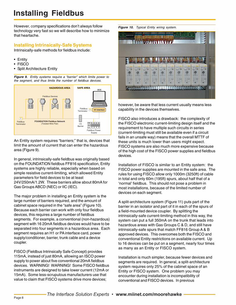
An alternative method is to use a fault-tolerant segmentwith parallel interface cards, parallel power conditioners,dual trunks and one field device coupler (Figure 8). Thiseliminates the need to duplicate field instruments andavoids difficult maintenance issues, while still improvingthe segment MTTF by 7-10 times at virtually no cost.The power conditioners determine when a cable breakoccurs, cut power to the failed trunk, and use the backupcable immediately. This “fault-tolerant” approachsimplifies installation, because it does not require anyspecial programming of the DCS.
When the fault-tolerant system detects a cable break, itdeprives the H1 card of power, so the DCS knows that afailure occurred and can switch to the backup H1 card. Italso gets an alarm from the power supply, indicating thata failure occurred. And, because the power conditionershave auto-termination capability, the proper segmenttermination is set automatically.
Installing Fieldbus
The Interface Solution Experts • www.miinet.com/moorehawkePage 7
The fault-tolerant system does not require any otherspecial hardware; in fact, the DIN-rail power conditionermodules can be installed in the same DIN rack asconventional modules. No special installation wiring isnecessary in the field. It is probably advisable to routethe two segment cables differently, so that the samephysical incident—such as a wayward forklift—does nottake out both cables at the same time.
If a certain type of field instrument is prone to failure, aredundant instrument can be installed, and wired into anyspare spur on the device coupler. The DCS, of course,has to be configured accordingly, so it recognizes adevice failure and knows to switch to the backupinstrument.
Working in Hazardous AreasThree methods are available for installing fieldbus inhazardous areas:
• Intrinsically-safe systems• Explosion-proof cabinets• Non-incendive equipment
Figure 8. A fault-tolerant fieldbus system has two segments. If afault occurs in one leg of the system, it automatically uses theother leg. It is not necessary to duplicate the field instruments.
On-Board Diagnostics Module (Optional) Provides Comprehensive Fieldbus Physical Layer Diagnostics
Digital Diagnostic Communications
DCS/H1Interface
RedundantFOUNDATION Fieldbus H1
Interfaces
BREAK!Uninterrupted
Fieldbus SegmentCommunications
DCS/H1Interface
T
Up to 350mA of Isolated, Redundantand ConditionedPower per Segment
Fieldbus Termination isAutomatically Switched to
the Side of the Trunk that isMaintaining Normal Communications
Auto-Detects Field Cable Failure and Then Prevents
Communications on that Side of the Trunk
TPS200
Segment Length Can Be Up to 1900m. Cable Lengths on Each Side Do Not Need to Be Balanced
T
T
Disconnects power to H1 card when short circuit detected
With TRUNKSAFE, it may not be necessary to duplicate all fieldbus instruments.
RedundantTPS200
Fault-TolerantPower
Supply/Conditioners
TS200 Fault-Tolerant Device Coupler
Intrinsically-safe (I.S.) circuit designs limit the electricalenergy at the device to a level below the explosive limitsof the environment and remain safe with a componentfailure. An intrinsically-safe circuit, as defined by theNEC, is “a circuit in which any spark or any thermaleffect is incapable of causing ignition of a mixture offlammable or combustible material in air under prescribedtest conditions.”
An I.S. circuit uses a safety device such as a safetybarrier to limit the power in the hazardous environmentand, because I.S. is considered to be very safe, this typeof system can be worked on while energized without gasclearance testing (commonly referred to as a “hot workpermit”).
An explosion-proof design and installation (flameproof/Exd in Europe) requires that if a fuel were ignited insidethe device enclosure, the enclosure will contain theenergy of ignition and disperse it into the classified areaat a level low enough to prevent a secondary ignition fromoccurring outside the enclosure. Explosion-proof designsrequire special installation methods, as well as requiringthe electrical devices and enclosures to be ratedexplosion-proof (NEMA 7/9) for the proper areaclassification. This type of system cannot be worked onwhile energized without a gas clearance certificate.
A non-incendive circuit, as defined by the NEC, is “acircuit, other than field wiring, in which any arc or thermaleffect produced under intended operating conditions ofthe equipment is not capable, under specified testconditions, of igniting the flammable gas-air, vapor-air ordust-air mixture.”
Non-incendive circuit designs do not take componentfailure into consideration, thereby offering a reduced levelof safety by comparison to the intrinsically-safe circuitdesign and are therefore only allowable in Division 2/Zone2. There are two fundamental types: non-arcing whichcannot be worked on while energized without gasclearance testing; and energy-limited, which is more likea poor man’s I.S. and can be disconnected “live.”
While all three methods have been used for fieldbusinstallations, the most popular—especially in Europe—isintrinsic safety. One might consider that this is anhistorical hangover: I.S. systems were great for analogelectronic modules that needed frequent access in thefield and for the adjustment of limit switches on valves.
Fieldbus devices have no physical adjustmentsaccessible in the field or otherwise, and all changes aremade through the segment communications, so puttingyourself through the pain of I.S. fieldbus (and it can bevery painful indeed) is not necessary at all!
Installing Fieldbus
However, company specifications don’t always followtechnology very fast so we will describe how to minimizethat heartache.
Installing Intrinsically-Safe SystemsIntrinsically-safe methods for fieldbus include:
• Entity• FISCO• Split Architecture Entity
Figure 9. Entity systems require a “barrier” which limits power tothe segment, and thus limits the number of fieldbus devices.
SAFE AREASAFE AREA
H1 Interface
Fieldbus Power Supply
DCS
I.S. Barrier
Fieldbus Terminator
FOUNDATION Fieldbus Network(Twisted Wire Pair)
Fieldbus Terminator
Fieldbus Devices
T
T
HAZARDOUS AREAHAZARDOUS AREA
An Entity system requires “barriers;” that is, devices thatlimit the amount of current that can enter the hazardousarea (Figure 9).
In general, intrinsically-safe fieldbus was originally basedon the FOUNDATION fieldbus FF816 specification, Entitysystems are highly reliable, especially when based onsimple resistive current-limiting, which allowed Entityparameters for field devices to be at least24V/250mA/1.2W. These barriers allow about 80mA forGas Groups ABCD (NEC) or IIC (IEC).
The major problem in installing an Entity system is thelarge number of barriers required, and the amount ofcabinet space required in the “safe area” (Figure 10).Because each barrier can work with only four fieldbusdevices, this requires a large number of fieldbussegments. For example, a conventional (non-hazardous)segment with 16 20mA fieldbus devices would have to beseparated into four segments in a hazardous area. Eachsegment requires an H1 or PA interface card, powersupply/conditioner, barrier, trunk cable and a devicecoupler.
FISCO (Fieldbus Intrinsically Safe Concept) provides115mA, instead of just 80mA, allowing an ISCO powersupply to power about five conventional 20mA fieldbusdevices. WARNING! WARNING! Some FISCO fieldbusinstruments are designed to take lower current (12mA or15mA). Some less-scrupulous manufacturers use thatvalue to claim that FISCO systems drive more devices;
The Interface Solution Experts • www.miinet.com/moorehawkePage 8
however, be aware that less current usually means lesscapability in the devices themselves.
FISCO also introduces a drawback: the complexity ofthe FISCO electronic current-limiting design itself and therequirement to have multiple such circuits in series(current-limiting must still be available even if a circuitfails in an unsafe way) means that the overall MTTF ofthese units is much lower than users might expect.FISCO systems are also much more expensive becauseof the high cost of the FISCO power supplies and fieldbusdevices.
Installation of FISCO is similar to an Entity system: theFISCO power supplies are mounted in the safe area. Therules for using FISCO allow only 1000m (3250ft) of cablein total and only 60m (195ft) spurs, about half that of a‘normal’ fieldbus. This should not pose a problem inmost installations, because of the limited number ofdevices on each segment.
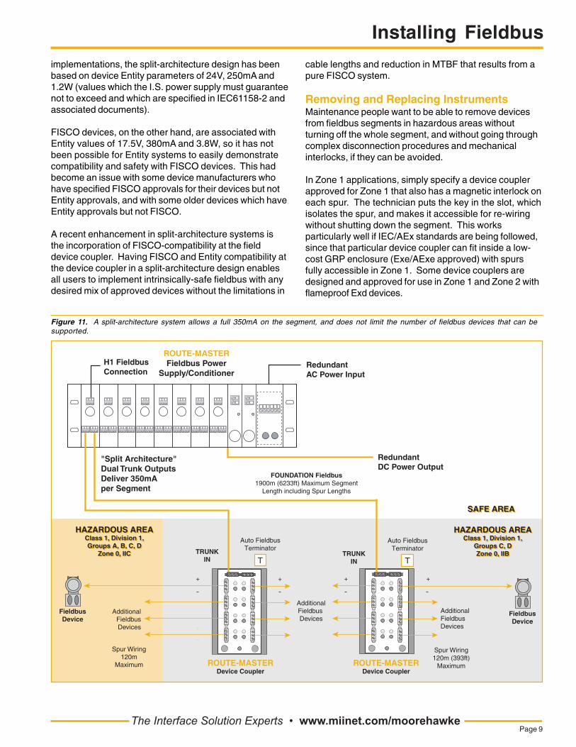
A split-architecture system (Figure 11) puts part of thebarrier in an isolator and part of it in each of the spurs ofa field-mounted device coupler. By splitting theintrinsically-safe current-limiting method in this way, thesystem can put a full 350mA on the trunk that leads intohazardous areas with Gas Groups C & D, and still haveintrinsically-safe spurs that match FF816 Group A & Bapproved devices. This overcomes both the FISCO andconventional Entity restrictions on available current. Upto 16 devices can be put on a segment, nearly four timesas many as an Entity or FISCO system.
Installation is much simpler, because fewer devices andsegments are required. In general, a split-architecturesystem requires only 25% of the cabinet space of anEntity or FISCO system. One problem you mayencounter during installation is incompatibility ofconventional and FISCO devices. In previous
Figure 10. Typical Entity wiring system.
Installing Fieldbus
The Interface Solution Experts • www.miinet.com/moorehawkePage 9
implementations, the split-architecture design has beenbased on device Entity parameters of 24V, 250mA and1.2W (values which the I.S. power supply must guaranteenot to exceed and which are specified in IEC61158-2 andassociated documents).
FISCO devices, on the other hand, are associated withEntity values of 17.5V, 380mA and 3.8W, so it has notbeen possible for Entity systems to easily demonstratecompatibility and safety with FISCO devices. This hadbecome an issue with some device manufacturers whohave specified FISCO approvals for their devices but notEntity approvals, and with some older devices which haveEntity approvals but not FISCO.
A recent enhancement in split-architecture systems isthe incorporation of FISCO-compatibility at the fielddevice coupler. Having FISCO and Entity compatibility atthe device coupler in a split-architecture design enablesall users to implement intrinsically-safe fieldbus with anydesired mix of approved devices without the limitations in
cable lengths and reduction in MTBF that results from apure FISCO system.
Removing and Replacing InstrumentsMaintenance people want to be able to remove devicesfrom fieldbus segments in hazardous areas withoutturning off the whole segment, and without going throughcomplex disconnection procedures and mechanicalinterlocks, if they can be avoided.
In Zone 1 applications, simply specify a device couplerapproved for Zone 1 that also has a magnetic interlock oneach spur. The technician puts the key in the slot, whichisolates the spur, and makes it accessible for re-wiringwithout shutting down the segment. This worksparticularly well if IEC/AEx standards are being followed,since that particular device coupler can fit inside a low-cost GRP enclosure (Exe/AExe approved) with spursfully accessible in Zone 1. Some device couplers aredesigned and approved for use in Zone 1 and Zone 2 withflameproof Exd devices.
Figure 11. A split-architecture system allows a full 350mA on the segment, and does not limit the number of fieldbus devices that can besupported.
SAFE AREA
Spur Wiring120m
Maximum
TRUNKIN
++
AdditionalFieldbusDevices
HAZARDOUS AREAClass 1, Division 1,Groups A, B, C, D
Zone 0, IIC
Spur Wiring120m (393ft)
Maximum
TRUNKIN
++
AdditionalFieldbus Devices
AdditionalFieldbus Devices
HAZARDOUS AREAClass 1, Division 1,
Groups C, DZone 0, IIB
SAFE AREA
ROUTE-MASTERDevice Coupler
FOUNDATION Fieldbus1900m (6233ft) Maximum Segment
Length including Spur Lengths
"Split Architecture" Dual Trunk Outputs Deliver 350mA per Segment
H1 FieldbusConnection
ROUTE-MASTERFieldbus Power
Supply/Conditioner
ROUTE-MASTERDevice Coupler
Auto FieldbusTerminator
T
Auto FieldbusTerminator
T
HAZARDOUS AREAClass 1, Division 1,
Groups C, DZone 0, IIB
FieldbusDevice
FieldbusDevice
HAZARDOUS AREAClass 1, Division 1,Groups A, B, C, D
Zone 0, IIC
RedundantAC Power Input
RedundantDC Power Output

Installing Fieldbus
For flameproof, Division 1 applications, live de-mateableplug/socket combinations are available from manymanufacturers. If an application demands live exposurein Division 1 or connection into Zone 0, then field barrierscan be used which allow intrinsically-safe spurs to beattached to the non-intrinsically safe trunk.
Cost issues involve the amount of time a maintenancetechnician must spend removing and replacinginstruments. If the process is laborious, it might takehours to follow all the safety procedures. If the processsimply requires a key, then an instrument can bedisconnected in a few seconds.
Simplify Your InstallationMany of the installation headaches discussed in thisarticle can be minimized through careful selection offieldbus equipment at the beginning of the project.
Few end users realize that fieldbus components, suchas power supplies and device couplers, are notmanufactured by the DCS vendor. Instead, they areprovided by associated suppliers, such as MooreHawke,and others. Therefore, even if a user is buying anEmerson DeltaV or a Yokogawa Centrum or a DCS fromany other supplier, it is possible to specify fieldbuscomponents separately. Note that the choice ofphysical layer product makes no difference to the DCSoperation. All fieldbus power conditioners and devicecouplers simply enable the fieldbus power andcommunications to work; they do not communicate withthe DCS.
To simplify installation of your fieldbus system, evaluatethe components carefully from the various suppliers.
Look for:
• Automatic Segment termination on device couplers toeliminate termination problems during installation,startup and regular maintenance.
• Foldback short circuit protection (which disconnects ashorted device from the spur) to eliminate the need toleave spurs empty.
• Power supplies with built-in power conditioning,redundancy, and surge protection.
Fieldbus is an exciting technology and there are manybenefits which will accrue to end users and earlyadopters. Implementation of real fieldbus systems is stilla new experience for many engineering companies, andmany subcontractors are coming to wire up deviceswithout any real understanding of the differentrequirements and problems presented by fieldbussystems. Keep some of the guidelines described here inmind when ordering your fieldbus system and whendealing with your installation subcontractor.
• www.miinet.comUnited States • [email protected]
Tel: (818) 894-7111 • FAX: (818) 891-2816
Australia • [email protected]: (02) 8536-7200 • FAX: (02) 9525-7296
Belgium • [email protected]: 03/448.10.18 • FAX: 03/440.17.97
The Netherlands • [email protected]: (0)344-617971 • FAX: (0)344-615920
China • [email protected]: 86-21-62491499 • FAX: 86-21-62490635
United Kingdom • [email protected]: 01293 514488 • FAX: 01293 536852
©2008 Moore Industries-International, Inc. Specifications and information subject to change without notice.All product names are trademarks of their respective companies.