excel and power 9000 - invacare corporation
TRANSCRIPT

��������������� �����������������
������������� ��������������� ��������������
�����������
��������������� ���������������������
�� ����� ������������������������ ���
�����
���
���� ���

2
WARNING
WARNING
SAVE THESE INSTRUCTIONS
WARNINGDO NOT OPERATE THIS EQUIPMENT WITHOUT FIRST READING AND
UNDERSTANDING THIS MANUAL. IF YOU ARE UNABLE TOUNDERSTAND THE WARNINGS, CAUTIONS, AND INSTRUCTIONS,
CONTACT A HEALTHCARE PROFESSIONAL, DEALER OR TECHNICALPERSONNEL IF APPLICABLE BEFORE ATTEMPTING TO USE THISEQUIPMENT - OTHERWISE INJURY OR DAMAGE MAY RESULT.
THE INITIAL SET UP OF THIS WHEELCHAIR MUST BE PERFORMED BYAN INVACARE DEALER OR QUALIFIED TECHNICIAN.
PROCEDURES OTHER THAN THOSE DESCRIBED IN THIS MANUALMUST BE PERFORMED BY AN INVACARE DEALER OR QUALIFIED
TECHNICIAN.
SPECIAL NOTESWARNING/CAUTION notices as used in this manual apply to hazards or unsafe practices which couldresult in personal injury or property damage.
NOTICETHE INFORMATION CONTAINED IN THIS DOCUMENT IS SUBJECT TO CHANGE WITHOUT NOTICE.
WHEELCHAIR USER
As a manufacturer of wheelchairs, Invacare endeavors to supply a wide variety of wheelchairsto meet many needs of the end user. However, final selection of the type of wheelchair to beused by an individual rests solely with the user and his/her healthcare professional capable ofmaking such a selection.
WHEELCHAIR TIE-DOWN RESTRAINTS AND SEAT POSITIONING STRAPS
Invacare recommends that wheelchair users NOT be transported in vehicles of any kind while in wheel-chairs. As of this date, the Department of Transportation has not approved any tie-down systems fortransportation of a user while in a wheelchair, in a moving vehicle of any type.It is Invacare’s position that users of wheelchairs should be transferred into appropriate seating in ve-hicles for transportation and use be made of the restraints made available by the auto industry. Invac-are cannot and does not recommend any wheelchair transportation systems.AS REGARDS RESTRAINTS - SEAT POSITIONING STRAPS - IT IS THE OBLIGATION OF THE DME DEALER, THERA-PISTS AND OTHER HEALTHCARE PROFESSIONALS TO DETERMINE IF A SEATING POSITIONING STRAP ISREQUIRED TO ENSURE THE SAFE OPERATION OF THIS EQUIPMENT BY THE USER. SERIOUS INJURY CANOCCUR IN THE EVENT OF A FALL FROM A WHEELCHAIR.

3
TABLE OF CONTENTS
TABLE
OF
CONTENTS
TABLE OF CONTENTS
SPECIAL NOTES ................................................................................................................................................ 2SPECIFICATIONS ............................................................................................................................................... 4PROCEDURE 1 - GENERAL GUIDELINES .......................................................................................................... 6
REPAIR OR SERVICE INFORMATION ............................................................................................................... 6OPERATING INFORMATION ............................................................................................................................. 6SAFETY/HANDLING OF WHEELCHAIRS .......................................................................................................... 8
PROCEDURE 2 - SAFETY INSPECTION CHECKLIST/TROUBLESHOOTING ..................................................... 13SAFETY INSPECTION CHECKLIST ................................................................................................................ 13TROUBLESHOOTING GUIDE - MECHANICAL ................................................................................................. 13TROUBLESHOOTING GUIDE - ELECTRICAL ................................................................................................... 14CHECKING BATTERY CHARGE LEVEL ........................................................................................................... 14
PROCEDURE 3 - FRONT RIGGINGS ................................................................................................................. 16INSTALLING/REMOVING FOOTRESTS ........................................................................................................... 16ADJUSTING FOOTREST HEIGHT ................................................................................................................... 17REPLACING HEEL LOOPS .............................................................................................................................. 17INSTALLING/REMOVING ELEVATING LEGRESTS ........................................................................................... 17RAISING/LOWERING ELEVATING LEGRESTS AND/OR ADJUSTING CALFPADS ............................................. 17
PROCEDURE 4 - ARMS ..................................................................................................................................... 18ADJUSTING ARMREST HEIGHT, REMOVING OR REPLACING ARMRESTS ................................................... 18ADJUSTING CAPTAIN'S SEAT ARMRESTS..................................................................................................... 18
PROCEDURE 5 - UPHOLSTERY/POSITIONING STRAP ..................................................................................... 19REPLACING SEAT UPHOLSTERY ................................................................................................................... 19REPLACING SEAT POSITIONING STRAP ........................................................................................................ 19
PROCEDURE 6 - ELECTRONICS ...................................................................................................................... 20PREPARING MKIV JOYSTICK FOR USE ......................................................................................................... 20REPOSITIONING MKIV JOYSTICK ................................................................................................................. 20
PROCEDURE 7 - RETAINING STRAP ............................................................................................................... 21REPLACING BATTERY BOX RETAINING STRAP ............................................................................................ 21
PROCEDURE 8 - CASTERS .............................................................................................................................. 22ADJUSTING FORKS ....................................................................................................................................... 22
PROCEDURE 9 - BATTERIES............................................................................................................................ 23INSTALLING/REMOVING BATTERIES INTO/FROM BATTERY BOXES ............................................................ 23CONNECTING BATTERY CABLES .................................................................................................................. 24
PROCEDURE 10 - FWD WHEELCHAIRS ........................................................................................................... 28TRANSPORTING EXCEL................................................................................................................................. 28ADJUSTING/REPLACING TELESCOPING FRONT RIGGING SUPPORT ........................................................... 29ADJUSTING FLIP-UP REMOVABLE FOOTBOARD ........................................................................................... 30ADJUSTING CAPTAIN'S SEAT ........................................................................................................................ 30REMOVING/INSTALLING CAPTAIN'S SEAT ..................................................................................................... 31DISCONNECTING/CONNECTING LIMIT SWITCH ........................................................................................... 31REMOVING/INSTALLING SHROUDS .............................................................................................................. 32REPOSITIONING BATTERY CHARGER CONNECTOR ................................................................................... 33WHEN TO CHARGE BATTERIES .................................................................................................................... 33CHARGING BATTERIES ................................................................................................................................. 34REPLACING BATTERIES ................................................................................................................................ 35INSTALLING/REMOVING BATTERY BOXES ................................................................................................... 36BATTERY TRAY .............................................................................................................................................. 36ENGAGING/DISENGAGING CLUTCHES ......................................................................................................... 37
PROCEDURE 11 - RWD WHEELCHAIRS ........................................................................................................... 38TRANSPORTING POWER 9000 ...................................................................................................................... 38WHEN TO CHARGE BATTERIES .................................................................................................................... 39CHARGING BATTERIES ................................................................................................................................. 39REPLACING BATTERIES ................................................................................................................................ 40INSTALLING/REMOVING BATTERY BOXES ................................................................................................... 41BATTERY TRAY .............................................................................................................................................. 41ENGAGING/DISENGAGING CLUTCHES ......................................................................................................... 41USING/INSTALLING/ADJUSTING WHEEL LOCKS .......................................................................................... 42INSTALLING/REMOVING ANTI-TIPPERS ........................................................................................................ 43INSTALLING OPTIONAL CLUTCH EXTENSION HANDLES .............................................................................. 44LIMITED WARRANTY ..................................................................................................................................... 47
The following procedures refer to POWER 9000 and EXCEL wheelchairs except where specified.
4
SPECIFICATIONS
SPECIFICATIONS
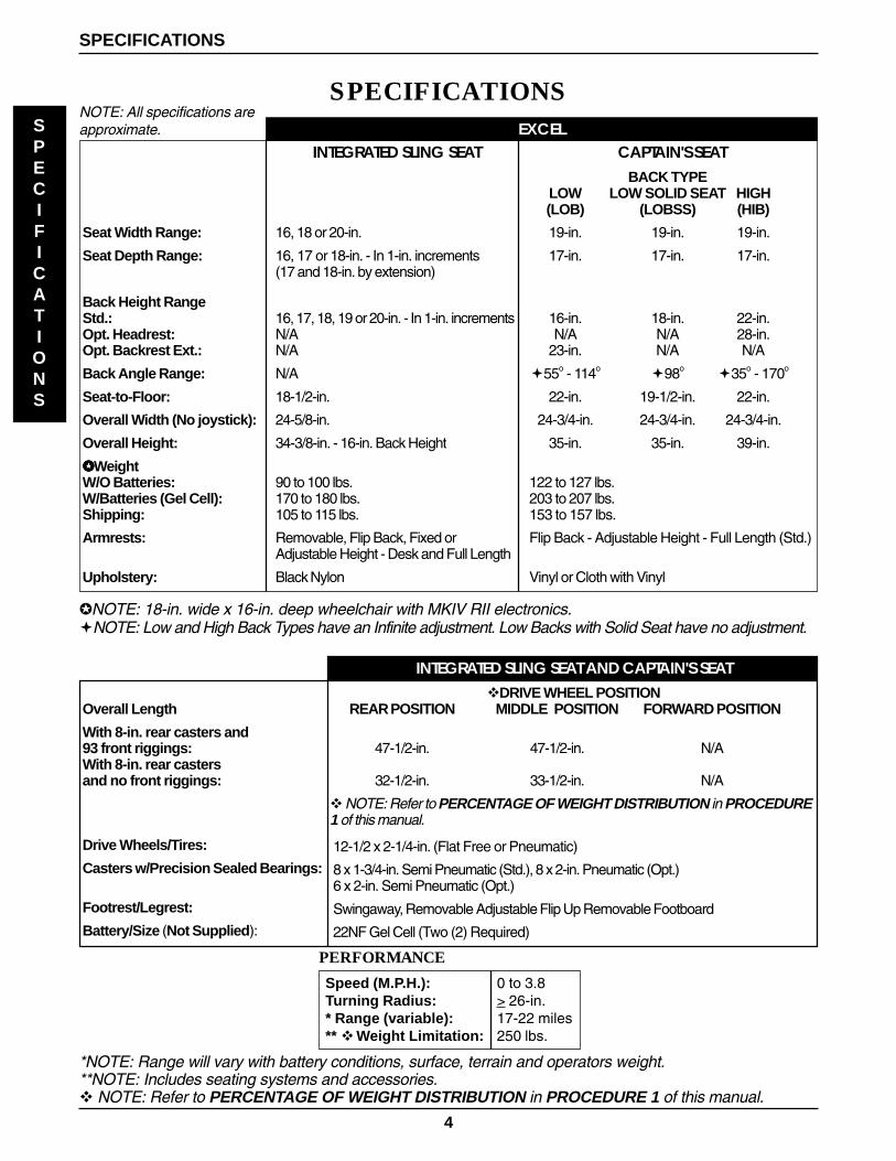
SPECIFICATIONSNOTE: All specifications areapproximate. EXCEL
Seat Width Range:
Seat Depth Range:
Back Height RangeStd.:Opt. Headrest:Opt. Backrest Ext.:
Back Angle Range:
Seat-to-Floor:
Overall Width (No joystick):
Overall Height:
✪✪✪✪✪ WeightW/O Batteries:W/Batteries (Gel Cell):Shipping:
Armrests:
Upholstery:
INTEGRATED SLING SEAT
16, 18 or 20-in.
16, 17 or 18-in. - In 1-in. increments(17 and 18-in. by extension)
16, 17, 18, 19 or 20-in. - In 1-in. incrementsN/AN/A
N/A
18-1/2-in.
24-5/8-in.
34-3/8-in. - 16-in. Back Height
90 to 100 lbs.170 to 180 lbs.105 to 115 lbs.
Removable, Flip Back, Fixed orAdjustable Height - Desk and Full Length
Black Nylon
✪ NOTE: 18-in. wide x 16-in. deep wheelchair with MKIV RII electronics.�NOTE: Low and High Back Types have an Infinite adjustment. Low Backs with Solid Seat have no adjustment.
CAPTAIN'S SEATBACK TYPE
LOW LOW SOLID SEAT HIGH(LOB) (LOBSS) (HIB)
19-in. 19-in. 19-in.
17-in. 17-in. 17-in.
16-in. 18-in. 22-in.N/A N/A 28-in.
23-in. N/A N/A
�55o - 114o�98o
�35o - 170o
22-in. 19-1/2-in. 22-in.
24-3/4-in. 24-3/4-in. 24-3/4-in.
35-in. 35-in. 39-in.
122 to 127 lbs.203 to 207 lbs.153 to 157 lbs.
Flip Back - Adjustable Height - Full Length (Std.)
Vinyl or Cloth with Vinyl
INTEGRATED SLING SEAT AND CAPTAIN'S SEAT�DRIVE WHEEL POSITION
REAR POSITION MIDDLE POSITION FORWARD POSITION
47-1/2-in. 47-1/2-in. N/A
32-1/2-in. 33-1/2-in. N/A
� NOTE: Refer to PERCENTAGE OF WEIGHT DISTRIBUTION in PROCEDURE1 of this manual.
12-1/2 x 2-1/4-in. (Flat Free or Pneumatic)
8 x 1-3/4-in. Semi Pneumatic (Std.), 8 x 2-in. Pneumatic (Opt.)6 x 2-in. Semi Pneumatic (Opt.)
Swingaway, Removable Adjustable Flip Up Removable Footboard
22NF Gel Cell (Two (2) Required)
Overall Length
With 8-in. rear casters and93 front riggings:With 8-in. rear castersand no front riggings:
Drive Wheels/Tires:
Casters w/Precision Sealed Bearings:
Footrest/Legrest:
Battery/Size (Not Supplied):
*NOTE: Range will vary with battery conditions, surface, terrain and operators weight.**NOTE: Includes seating systems and accessories.� NOTE: Refer to PERCENTAGE OF WEIGHT DISTRIBUTION in PROCEDURE 1 of this manual.
PERFORMANCE
Speed (M.P.H.): 0 to 3.8Turning Radius: > 26-in.* Range (variable): 17-22 miles** � Weight Limitation: 250 lbs.
5
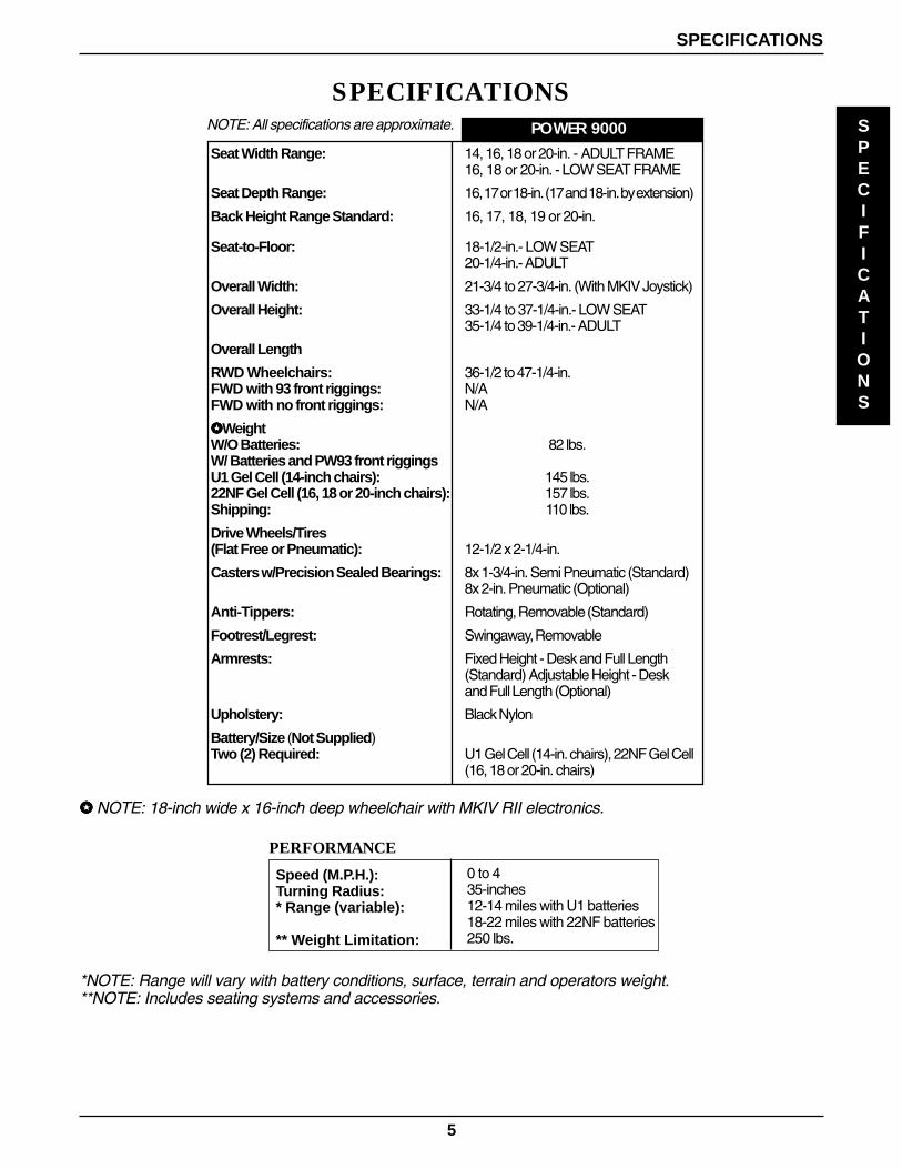
*NOTE: Range will vary with battery conditions, surface, terrain and operators weight.**NOTE: Includes seating systems and accessories.
SPECIFICATIONS
Speed (M.P.H.):Turning Radius:* Range (variable):
** Weight Limitation:
0 to 435-inches12-14 miles with U1 batteries18-22 miles with 22NF batteries250 lbs.
PERFORMANCE
✪✪✪✪✪ NOTE: 18-inch wide x 16-inch deep wheelchair with MKIV RII electronics.
POWER 9000NOTE: All specifications are approximate.
Seat Width Range:
Seat Depth Range:
Back Height Range Standard:
Seat-to-Floor:
Overall Width:
Overall Height:
Overall Length
RWD Wheelchairs:FWD with 93 front riggings:FWD with no front riggings:
✪✪✪✪✪ WeightW/O Batteries:W/ Batteries and PW93 front riggingsU1 Gel Cell (14-inch chairs):22NF Gel Cell (16, 18 or 20-inch chairs):Shipping:
Drive Wheels/Tires(Flat Free or Pneumatic):
Casters w/Precision Sealed Bearings:
Anti-Tippers:
Footrest/Legrest:
Armrests:
Upholstery:
Battery/Size (Not Supplied)Two (2) Required:
14, 16, 18 or 20-in. - ADULT FRAME16, 18 or 20-in. - LOW SEAT FRAME
16, 17 or 18-in. (17 and 18-in. by extension)
16, 17, 18, 19 or 20-in.
18-1/2-in.- LOW SEAT20-1/4-in.- ADULT
21-3/4 to 27-3/4-in. (With MKIV Joystick)
33-1/4 to 37-1/4-in.- LOW SEAT35-1/4 to 39-1/4-in.- ADULT
36-1/2 to 47-1/4-in.N/AN/A
82 lbs.
145 lbs.157 lbs.110 lbs.
12-1/2 x 2-1/4-in.
8x 1-3/4-in. Semi Pneumatic (Standard)8x 2-in. Pneumatic (Optional)
Rotating, Removable (Standard)
Swingaway, Removable
Fixed Height - Desk and Full Length(Standard) Adjustable Height - Deskand Full Length (Optional)
Black Nylon
U1 Gel Cell (14-in. chairs), 22NF Gel Cell(16, 18 or 20-in. chairs)
SPECIFICATIONS
SPECIFICATIONS
6
GENERAL GUIDELINESPROCEDURE 1
GENERAL
GUIDELINES
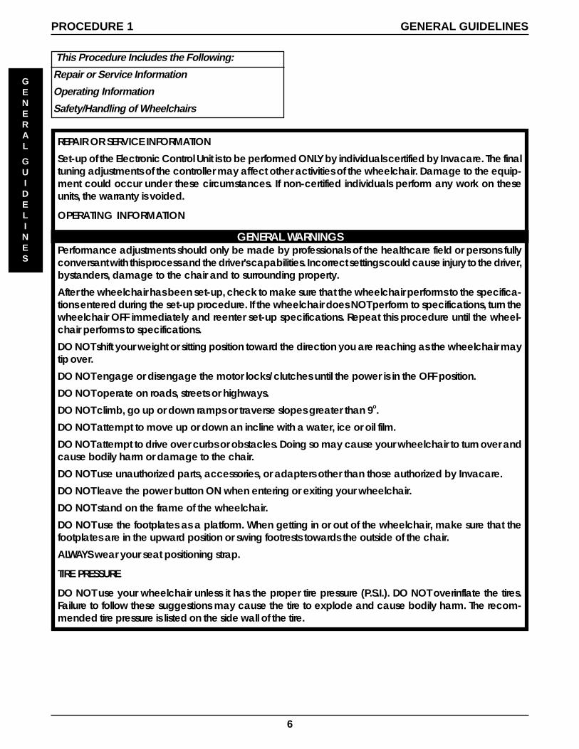
This Procedure Includes the Following:
Repair or Service Information
Operating Information
Safety/Handling of Wheelchairs
REPAIR OR SERVICE INFORMATION
Set-up of the Electronic Control Unit is to be performed ONLY by individuals certified by Invacare. The finaltuning adjustments of the controller may affect other activities of the wheelchair. Damage to the equip-ment could occur under these circumstances. If non-certified individuals perform any work on theseunits, the warranty is voided.
OPERATING INFORMATION
GENERAL WARNINGSPerformance adjustments should only be made by professionals of the healthcare field or persons fullyconversant with this process and the driver's capabilities. Incorrect settings could cause injury to the driver,bystanders, damage to the chair and to surrounding property.
After the wheelchair has been set-up, check to make sure that the wheelchair performs to the specifica-tions entered during the set-up procedure. If the wheelchair does NOT perform to specifications, turn thewheelchair OFF immediately and reenter set-up specifications. Repeat this procedure until the wheel-chair performs to specifications.
DO NOT shift your weight or sitting position toward the direction you are reaching as the wheelchair maytip over.
DO NOT engage or disengage the motor locks/clutches until the power is in the OFF position.
DO NOT operate on roads, streets or highways.
DO NOT climb, go up or down ramps or traverse slopes greater than 9o.
DO NOT attempt to move up or down an incline with a water, ice or oil film.
DO NOT attempt to drive over curbs or obstacles. Doing so may cause your wheelchair to turn over andcause bodily harm or damage to the chair.
DO NOT use unauthorized parts, accessories, or adapters other than those authorized by Invacare.
DO NOT leave the power button ON when entering or exiting your wheelchair.
DO NOT stand on the frame of the wheelchair.
DO NOT use the footplates as a platform. When getting in or out of the wheelchair, make sure that thefootplates are in the upward position or swing footrests towards the outside of the chair.
ALWAYS wear your seat positioning strap.
TIRE PRESSURE
DO NOT use your wheelchair unless it has the proper tire pressure (P.S.I.). DO NOT overinflate the tires.Failure to follow these suggestions may cause the tire to explode and cause bodily harm. The recom-mended tire pressure is listed on the side wall of the tire.

7
GENERAL WARNINGS (CONTINUED)ELECTRICALEXTREME care should be exercised when using oxygen in close proximity to electric circuits. Contactyour oxygen supplier for instruction in the use of oxygen.Grounding Instructions:DO NOT, under any circumstances, cut or remove the round grounding prong from any plug used withor for Invacare products. Some devices are equipped with three-prong (grounding) plugs for protec-tion against possible shock hazards. Where a two-prong wall receptacle is encountered, it is the per-sonal responsibility and obligation of the customer to contact a qualified electrician and have thetwo-prong receptacle replaced with a properly grounded three-prong wall receptacle in accor-dance with the National Electrical Code. If you must use an extension cord, use ONLY a three-wireextension cord having the same or higher electrical rating as the device being connected. In addi-tion, Invacare has placed RED/ORANGE WARNING TAGS on some equipment. DO NOT remove thesetags. Carefully read battery/battery charger information prior to installing, servicing or operating yourwheelchair.
BATTERIESOnly deep cycle, sealed case construction batteries should be used in this device.
RAIN TESTINVACARE has tested it’s power wheelchairs in accordance with ISO 7176 Part 9 “Rain Test”. This pro-vides the end user or his/her attendant sufficient time to remove his/her power wheelchair from a rainstorm and retain wheelchair operation.DO NOT leave power wheelchair in a rain storm of any kind.DO NOT use power wheelchair in a shower or leave it in a damp bathroom while taking a shower.DO NOT leave power wheelchair in a damp area for any length of time.Direct exposure to rain or dampness will cause the chair to malfunction electrically and mechanically;may cause the chair to prematurely rust.Check to ensure that the battery covers are secured in place, joystick boot is NOT torn or crackedwhere water can enter and that all electrical connections are secure at all times.DO NOT use the joystick if the boot is torn or cracked. If the joystick boot becomes torn or cracked,replace IMMEDIATELY.
WEIGHT TRAININGInvacare DOES NOT recommend the use of its wheelchairs as a weight training apparatus. Invacarewheelchairs have NOT been designed or tested as a seat for any kind of weight training. If occupant usessaid wheelchair as a weight training apparatus, INVACARE SHALL NOT BE LIABLE FOR BODILY INJURY ANDTHE WARRANTY IS VOID.
WEIGHT LIMITATIONThe EXCEL has a weight limitation of 250 lbs. Refer to PERCENTAGE OF WEIGHT DISTRIBUTION in PRO-CEDURE 1 of this manual.The Power 9000 has a weight limitation of 250 lbs.Invacare recommends that only heavy-duty constructed wheelchairs should be used for indi-viduals weighing more than 250 lbs. Further, the activity level of the individual wheelchair user isimportant. For instance, a 170 lbs. active wheelchair user could subject the wheelchair to morestress than a 250 lbs. user. Invacare recommends that very active users consider the use of heavy-duty constructed wheelchairs.
GENERAL GUIDELINES PROCEDURE 1
GENERAL
GUIDELINES
8
GENERAL GUIDELINESPROCEDURE 1
GENERAL
GUIDELINES
SAFETY/HANDLING OFWHEELCHAIRS“Safety and Handling” of the wheelchair requires the closeattention of the wheelchair user as well as the assistant. Thismanual points out the most common procedures and tech-niques involved in the safe operation and maintenance ofthe wheelchair. It is important to practice and master thesesafe techniques until you are comfortable in maneuveringaround the frequently encountered architectural barriers.
Use this information only as a “basic” guide. The techniquesthat are discussed on the following pages have been usedsuccessfully by many.
Individual wheelchair users often develop skills to deal withdaily living activities that may differ from those described inthis manual. Invacare recognizes and encourages each in-dividual to try what works best for him/her in overcomingarchitectural obstacles that they may encounter, however,ALL WARNINGS and CAUTIONS given in this manualMUST be followed. Techniques in this manual are a start-ing point for the new wheelchair user and assistant with“safety” as the most important consideration for all.
Stability and Balance
WARNINGALWAYS wear your seat positioning strap.
To assure stability and proper operation of your wheelchair,you must at all times maintain proper balance. Your wheel-chair has been designed to remain upright and stable duringnormal daily activities as long as you do not move beyondthe center of gravity. DO NOT lean forward out of the wheel-chair any further than the length of the armrests.
Coping With Everyday Obstacles
Coping with the irritation of everyday obstacles can be allevi-ated somewhat by learning how to manage your wheel-chair. Keep in mind your center of gravity to maintain stabilityand balance.
A Note to Wheelchair Assistants
When assistance to the wheelchair user is required, remem-ber to use good body mechanics. Keep your back straightand bend your knees whenever tilting wheelchair or travers-ing curbs, or other impediments.
WARNINGDO NOT attempt to lift the wheelchair by any re-movable (detachable) parts. Lifting by means ofany removable (detachable) parts of a wheelchairmay result in injury to the user or damage to thewheelchair.
Also, be aware of detachable parts such as arms or leg-rests. These must NEVER be used for hand-hold or liftingsupports, as they may be inadvertently released, resulting inpossible injury to the user and/or assistant(s).
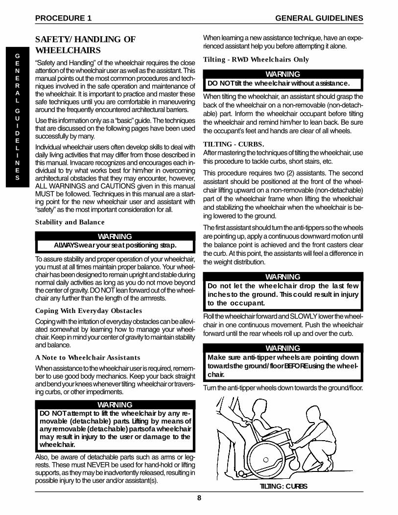
TILTING: CURBS
When learning a new assistance technique, have an expe-rienced assistant help you before attempting it alone.
Tilting - RWD Wheelchairs Only
WARNINGDO NOT tilt the wheelchair without assistance.
When tilting the wheelchair, an assistant should grasp theback of the wheelchair on a non-removable (non-detach-able) part. Inform the wheelchair occupant before tiltingthe wheelchair and remind him/her to lean back. Be surethe occupant’s feet and hands are clear of all wheels.
TILTING - CURBS.After mastering the techniques of tilting the wheelchair, usethis procedure to tackle curbs, short stairs, etc.
This procedure requires two (2) assistants. The secondassistant should be positioned at the front of the wheel-chair lifting upward on a non-removable (non-detachable)part of the wheelchair frame when lifting the wheelchairand stabilizing the wheelchair when the wheelchair is be-ing lowered to the ground.
The first assistant should turn the anti-tippers so the wheelsare pointing up, apply a continuous downward motion untilthe balance point is achieved and the front casters clearthe curb. At this point, the assistants will feel a difference inthe weight distribution.
WARNINGDo not let the wheelchair drop the last fewinches to the ground. This could result in injuryto the occupant.
Roll the wheelchair forward and SLOWLY lower the wheel-chair in one continuous movement. Push the wheelchairforward until the rear wheels roll up and over the curb.
WARNINGMake sure anti-tipper wheels are pointing downtowards the ground/floor BEFORE using the wheel-chair.
Turn the anti-tipper wheels down towards the ground/floor.
9
Stairways
WARNINGDO NOT attempt to move an occupied powerwheelchair between floors using a stairway. Use anelevator to move an occupied power wheelchairbetween floors. If moving a power wheelchair be-tween floors by means of a stairway, the occupantMUST be removed and transported independentlyof the power wheelchair.Extreme caution is advised when it is necessary tomove an UNOCCUPIED power wheelchair up ordown the stairs. Invacare recommends using two(2) assistants and making thorough preparations.Make sure to use ONLY secure, non-detachableparts for hand-hold supports.DO NOT attempt to lift the wheelchair by any re-movable (detachable) parts. Lifting by means ofany removable (detachable) parts of a wheelchairmay result in injury to the user or damage to thewheelchair.
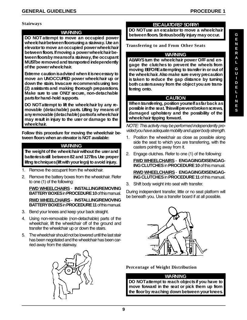
Follow this procedure for moving the wheelchair be-tween floors when an elevator is NOT available:
WARNINGThe weight of the wheelchair without the user andbatteries is still between 82 and 127lbs. Use properliftng techniques (lift with your legs) to avoid injury.
1. Remove the occupant from the wheelchair.
2. Remove the battery boxes from the wheelchair. Referto one (1) of the following:
FWD WHEELCHAIRS - INSTALLING/REMOVINGBATTERY BOXES in PROCEDURE 10 of this manual.
RWD WHEELCHAIRS - INSTALLING/REMOVINGBATTERY BOXES in PROCEDURE 11 of this manual.
3. Bend your knees and keep your back straight.
4. Using non-removable (non-detachable) parts of thewheelchair, lift the wheelchair off of the ground andtransfer the wheelchair up or down the stairs.
5. The wheelchair should not be lowered until the last stairhas been negotiated and the wheelchair has been car-ried away from the stairway.
Percentage of Weight Distribution
WARNINGDO NOT attempt to reach objects if you have tomove forward in the seat or pick them up fromthe floor by reaching down between your knees.
ESCALATORS? SORRY!DO NOT use an escalator to move a wheelchairbetween floors. Serious bodily injury may occur.
Transferring to and From Other Seats
WARNINGALWAYS turn the wheelchair power OFF and en-gage the clutches to prevent the wheels frommoving BEFORE attempting to transfer in or out ofthe wheelchair. Also make sure every precautionis taken to reduce the gap distance by turningboth casters away from the object you are trans-ferring onto.
CAUTIONWhen transferring, position yourself as far back aspossible in the seat. This will prevent broken screws,damaged upholstery and the possibility of thewheelchair tipping forward.
NOTE: This activity may be performed independently pro-vided you have adequate mobility and upper body strength.
1. Position the wheelchair as close as possible alongside the seat to which you are transferring, with thecasters pointing away from it.
2. Engage clutches. Refer to one (1) of the following:
FWD WHEELCHAIRS - ENGAGING/DISENGAG-ING CLUTCHES in PROCEDURE 10 of this manual.
RWD WHEELCHAIRS - ENGAGING/DISENGAG-ING CLUTCHES in PROCEDURE 11 of this manual.
3. Shift body weight into seat with transfer.
During independent transfer, little or no seat platform willbe beneath you. Use a transfer board if at all possible.
GENERAL
GUIDELINES
GENERAL GUIDELINES PROCEDURE 1
10
GENERAL GUIDELINESPROCEDURE 1
GENERAL
GUIDELINES
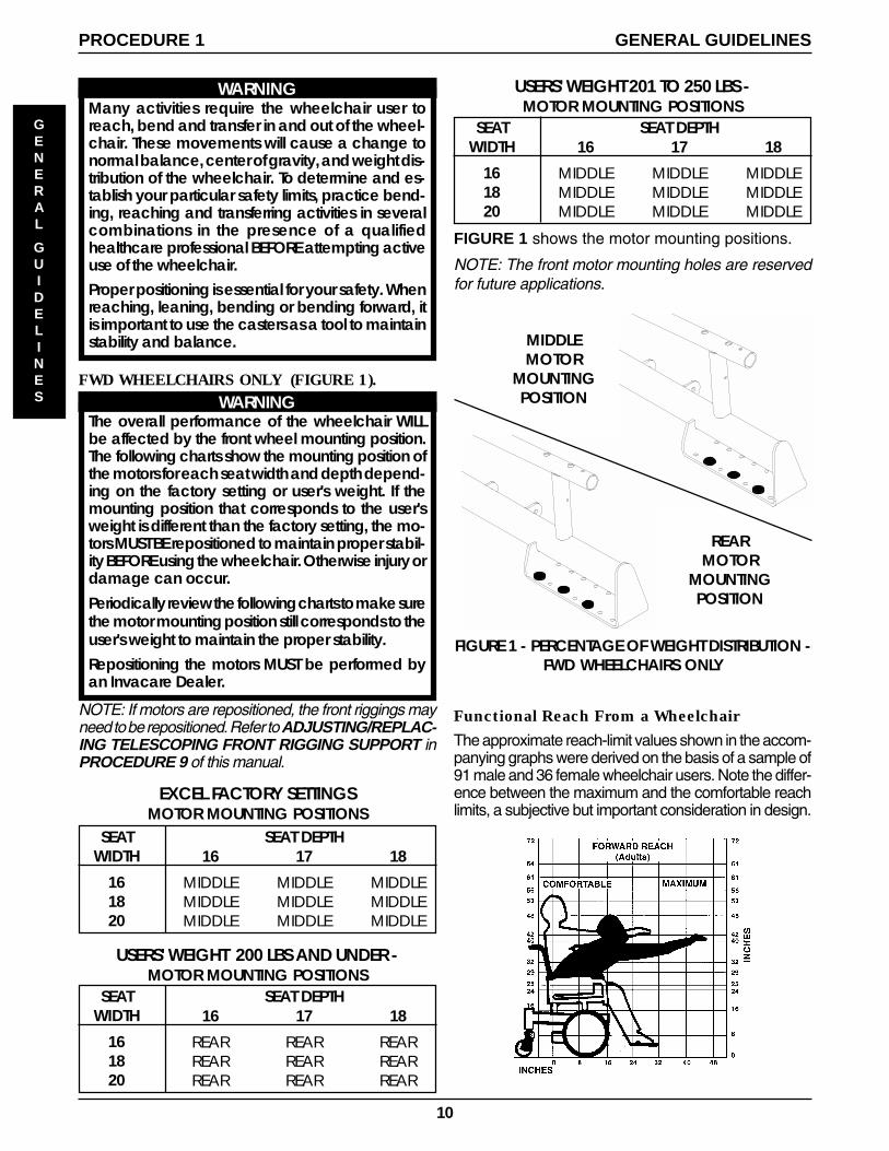
FIGURE 1 shows the motor mounting positions.
NOTE: The front motor mounting holes are reservedfor future applications.
Functional Reach From a Wheelchair
The approximate reach-limit values shown in the accom-panying graphs were derived on the basis of a sample of91 male and 36 female wheelchair users. Note the differ-ence between the maximum and the comfortable reachlimits, a subjective but important consideration in design.
REARMOTOR
MOUNTINGPOSITION
MIDDLEMOTOR
MOUNTINGPOSITION
FIGURE 1 - PERCENTAGE OF WEIGHT DISTRIBUTION -FWD WHEELCHAIRS ONLY
SEATWIDTH
161820
SEAT DEPTH16
MIDDLEMIDDLEMIDDLE
17
MIDDLEMIDDLEMIDDLE
18
MIDDLEMIDDLEMIDDLE
EXCEL FACTORY SETTINGSMOTOR MOUNTING POSITIONS
SEATWIDTH
161820
SEAT DEPTH16
REARREARREAR
17
REARREARREAR
18
REARREARREAR
USERS' WEIGHT 200 LBS AND UNDER -MOTOR MOUNTING POSITIONS
SEATWIDTH
161820
SEAT DEPTH16
MIDDLEMIDDLEMIDDLE
17
MIDDLEMIDDLEMIDDLE
18
MIDDLEMIDDLEMIDDLE
USERS' WEIGHT 201 TO 250 LBS -MOTOR MOUNTING POSITIONS
WARNINGMany activities require the wheelchair user toreach, bend and transfer in and out of the wheel-chair. These movements will cause a change tonormal balance, center of gravity, and weight dis-tribution of the wheelchair. To determine and es-tablish your particular safety limits, practice bend-ing, reaching and transferring activities in severalcombinations in the presence of a qualifiedhealthcare professional BEFORE attempting activeuse of the wheelchair.Proper positioning is essential for your safety. Whenreaching, leaning, bending or bending forward, itis important to use the casters as a tool to maintainstability and balance.
FWD WHEELCHAIRS ONLY (FIGURE 1).WARNING
The overall performance of the wheelchair WILLbe affected by the front wheel mounting position.The following charts show the mounting position ofthe motors for each seat width and depth depend-ing on the factory setting or user's weight. If themounting position that corresponds to the user'sweight is different than the factory setting, the mo-tors MUST BE repositioned to maintain proper stabil-ity BEFORE using the wheelchair. Otherwise injury ordamage can occur.Periodically review the following charts to make surethe motor mounting position still corresponds to theuser's weight to maintain the proper stability.Repositioning the motors MUST be performed byan Invacare Dealer.
NOTE: If motors are repositioned, the front riggings mayneed to be repositioned. Refer to ADJUSTING/REPLAC-ING TELESCOPING FRONT RIGGING SUPPORT inPROCEDURE 9 of this manual.
11
WARNINGCAUTION: IT IS VERY IMPORTANT THAT YOU READ THIS INFORMATION REGARDING THE POSSIBLE EFFECTSOF ELECTROMAGNETIC INTERFERENCE ON YOUR POWERED WHEELCHAIR.
Electromagnetic Interference (EMI) From Radio Wave sources
Powered wheelchairs and motorized scooters (in this text, both will be referred to as powered wheel-chairs) may be susceptible to electromagnetic interference (EMI), which is interfering electromagneticenergy (EM) emitted from sources such as radio stations, TV stations, amateur radio (HAM) transmitters,two way radios, and cellular phones. The interference (from radio wave sources) can cause the pow-ered wheelchair to release its brakes, move by itself, or move in unintended directions. It can also perma-nently damage the powered wheelchair's control system. The intensity of the interfering EM energy canbe measured in volts per meter (V/m). Each powered wheelchair can resist EMI up to a certain intensity.This is called its "immunity level." The higher the immunity level, the greater the protection. At this time,current technology is capable of achieving at least a 20 V/m immunity level, which would provide usefulprotection from the more common sources of radiated EMI. This powered wheelchair model as shipped,has an unknown immunity level.
There are a number of sources of relatively intense electromagnetic fields in the everyday environment.Some of these sources are obvious and easy to avoid. Others are not apparent and exposure is unavoid-able. However, we believe that by following the warnings listed below, your risk to EMI will be minimized.
Reaching, Leaning, Bending and Bending -Forward
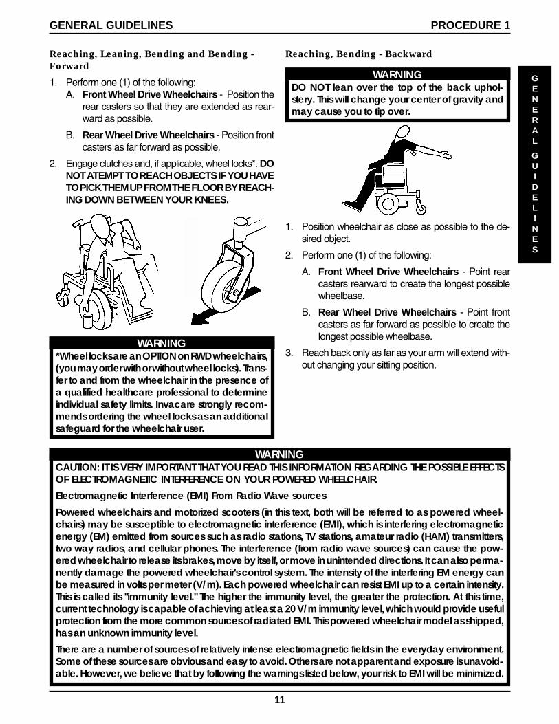
1. Perform one (1) of the following:A. Front Wheel Drive Wheelchairs - Position the
rear casters so that they are extended as rear-ward as possible.
B. Rear Wheel Drive Wheelchairs - Position frontcasters as far forward as possible.
2. Engage clutches and, if applicable, wheel locks*. DONOT ATEMPT TO REACH OBJECTS IF YOU HAVETO PICK THEM UP FROM THE FLOOR BY REACH-ING DOWN BETWEEN YOUR KNEES.
Reaching, Bending - Backward
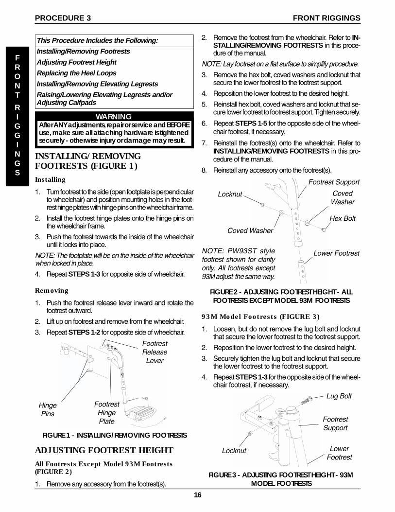
WARNINGDO NOT lean over the top of the back uphol-stery. This will change your center of gravity andmay cause you to tip over.
1. Position wheelchair as close as possible to the de-sired object.
2. Perform one (1) of the following:
A. Front Wheel Drive Wheelchairs - Point rearcasters rearward to create the longest possiblewheelbase.
B. Rear Wheel Drive Wheelchairs - Point frontcasters as far forward as possible to create thelongest possible wheelbase.
3. Reach back only as far as your arm will extend with-out changing your sitting position.
WARNING*Wheel locks are an OPTION on RWD wheelchairs,(you may order with or without wheel locks). Trans-fer to and from the wheelchair in the presence ofa qualified healthcare professional to determineindividual safety limits. Invacare strongly recom-mends ordering the wheel locks as an additionalsafeguard for the wheelchair user.
GENERAL
GUIDELINES
GENERAL GUIDELINES PROCEDURE 1

12
WARNINGThe sources of radiated EMI can be broadly classified into three types:
1) Hand-held Portable transceivers (transmitters-receivers with the antenna mounted directly on thetransmitting unit. Examples include: citizens band (CB) radios, "walkie talkie", security, fire and policetransceivers, cellular telephones, and other personal communication devices. **NOTE: Some cellu-lar telephones and similar devices transmit signals while they are ON, even when not being used;
2) Medium-range mobile transceivers, such as those used in police cars, fire trucks, ambulances, andtaxis. These usually have the antenna mounted on the outside of the vehicle; and
3) Long-range transmitters and transceivers, such as commercial broadcast transmitters (radio and TVbroadcast antenna towers) and amateur (HAM) radios.
NOTE: Other types of hand-held devices, such as cordless phones, laptop computers, AM/FM radios, TVsets, CD players, cassette players, and small appliances, such as electric shavers and hair dryers, so far aswe know, are not likely to cause EMI problems to your powered wheelchair.
Powered Wheelchair Electromagnetic Interference (EMI)
Because EM energy rapidly becomes more intense as one moves closer to the transmitting antenna(source), the EM fields from hand-held radio wave sources (transceivers) are of special concern. It ispossible to unintentionally bring high levels of EM energy very close to the powered wheelchair's controlsystem while using these devices. This can affect powered wheelchair movement and braking. There-fore, the warnings listed below are recommended to prevent possible interference with the controlsystem of the powered wheelchair.
Electromagnetic interference (EMI) from sources such as radio and TV stations, amateur radio (HAM)transmitters, two-way radios, and cellular phones can affect powered wheelchairs and motorized scoot-ers. Following the warnings listed below should reduce the chance of unintended brake release or pow-ered wheelchair movement which could result in serious injury.
1) Do not operate hand-held transceivers (transmitters receivers), such as citizens band (CB) radios, orturn ON personal communication devices, such as cellular phones, while the powered wheelchairis turned ON;
2) Be aware of nearby transmitters, such as radio or TV stations, and try to avoid coming close to them;
3) If unintended movement or brake release occurs, turn the powered wheelchair OFF as soon as it issafe;
4) Be aware that adding accessories or components, or modifying the powered wheelchair, maymake it more susceptible to EMI (Note: There is no easy way to evaluate their effect on the overallimmunity of the powered wheelchair); and
5) Report all incidents of unintended movement or brake release to the powered wheelchair manu-facturer, and note whether there is a source of EMI nearby.
Important Information
1) 20 volts per meter (V/m) is a generally achievable and useful immunity level against EMI (as of May1994) (the higher the level, the greater the protection);
2) The MCC MKIVcontroller for this application has an unknown immunity level.
Modification of any kind to the electronics of this wheelchair as manufactured by Invacare may ad-versely affect the RFI immunity levels.
GENERAL GUIDELINESPROCEDURE 1
GENERAL
GUIDELINES

13
SAFETY INSPECTION/TROUBLESHOOTING PROCEDURE 2
TROUBLESHOOTING
SAFETY
INSPECTION
SAFETY INSPECTION CHECKLIST
This Procedure Includes the Following:
Safety Inspection ChecklistTroubleshooting - MechanicalTroubleshooting - Electrical
Initial adjustments should be made to suit personal body structure and preference. Thereafter follow these maintenance procedures:
NOTE: Every six (6) months take your wheelchair to a qualified dealer for a thorough inspection and servicing. Regular cleaning willreveal loose or worn parts and enhance the smooth operation of your wheelchair. To operate properly and safely, your wheelchairmust be cared for just like any other vehicle. Routine maintenance will extend the life and efficiency of your wheelchair.
ITEM
GENERAL (MECHANICAL TROUBLESHOOTING)� Wheelchair rolls straight (no excessive drag or pull to one side).
CLOTHING GUARDS� Ensure all fasteners are secure.
ARMS - (PROCEDURE 4)� Secure but easy to release; adjustment levers engage properly.� Adjustable height arms operate and lock securely.
* WHEEL LOCKS (RWD WHEELCHAIRS ONLY) - (PROCEDURE 11 )� Do not interfere with tires when rolling.� Pivot points free of wear and looseness.� Wheel locks easy to engage.
SEAT AND BACK UPHOLSTERY� Inspect for rips or sagging.
DRIVE WHEELS� Axle bolts and locking tab washers are secure.� No excessive side movement or binding when lifted and spun when disengaged (free-
wheeling).
CASTERS - (PROCEDURE 8)� Inspect wheel/fork assembly for proper tension by spinning caster; caster should come to
a gradual stop.� Loosen/tighten locknut if wheel wobbles noticeably or binds to a stop.CAUTION: As with any vehicle, the wheels and tires should be checked periodicallyfor cracks and wear, and should be replaced.
CASTER/WHEEL/FORK/HEAD TUBE - (PROCEDURE 8)� Ensure all fasteners are secure.
TIRES� Inspect for flat spots and wear.� If pneumatic tires check for proper inflation.CAUTION: As with any vehicle, the wheels and tires should be checked periodicallyfor cracks and wear, and should be replaced.
CLEANING� Clean upholstery and armrests.
INITIALLY
X
X
XX
XXX
X
X
X
XXX
X
XX
X
INSPECT/ADJUSTWEEKLY
X
XX
INSPECT/ADJUST
MONTHLY
XX
XX
INSPECT/ADJUST
PERIODICALLY
X
X
XX
X
X
X
Checking Battery Charge Level
TROUBLESHOOTING - MECHANICALSOLUTIONS
If pneumatic, check tires for cor-rect and equal pressure.
Check for loose stem nuts/bolts.
Check that both casters contactground at the same time.
CHAIR 3WHEELS
X
LOOSENESSIN CHAIR
X
SQUEAKS ANDRATTLES
X
CASTERSFLUTTER
X
X
X
SLUGGISH TURN/PERFORMANCE
X
X
CHAIR VEERSLEFT/RIGHT
X
X
X
WARNING*Wheel locks are an OPTION on RWD wheelchairs, (you may order with or without wheel locks). Transfer to and from thewheelchair in the presence of a qualified healthcare professional to determine individual safety limits. Invacare strongly recom-mends ordering the wheel locks as an additional safeguard for the wheelchair user.

14
SAFETY
INSPECTION
SAFETY INSPECTION/TROUBLESHOOTINGPROCEDURE 2
TROUBLESHOOTING
TROUBLESHOOTING - ELECTRICAL
NOTE: For additional troubleshooting information and explanation of error codes, refer to the individual CONTROLLERMANUAL supplied with each wheelchair.
SYMPTOM
Batteries draw excessive currentwhen charging.
Battery indicator flashes the chargelevel is low—immediately after re-charge.
Battery indicator flashes the chargelevel is low—too soon after beingrecharged.
Motor “chatters” or runs irregular.
Wheelchair does not respond tocommands. Power "ON", batteryindicator flashes.
Only one (1) drive wheel turns.
Joystick erratic or does not respondas desired.
Wheelchair does not respond tocommands. Power indicator OFF—even after recharging.
SOLUTIONS
Check batteries for shorted cell. Replace if nec-essary (FWD - PROCEDURE 10, RWD - PROCE-DURE 11).
Contact Dealer/Invacare for Service.
Check batteries for shorted cell. Replace if nec-essary (FWD - PROCEDURE 10, RWD - PROCE-DURE 11).
Contact Dealer/Invacare for Service.
Poor connections between charger and wheel-chair. Contact Dealer/Invacare for Service.
Have charger checked.
Replace batteries if necessary (FWD - PROCE-DURE 10, RWD - PROCEDURE 11).
Contact Dealer/Invacare for Service.
Contact Dealer/Invacare for Service.
Engage motor locks/clutches (FWD - PROCE-DURE 10, RWD - PROCEDURE 11).
Contact Dealer/Invacare for Service.
Engage clutch (FWD - PROCEDURE 10, RWD -PROCEDURE 11).
Contact Dealer/Invacare for Service.
Reprogram controller (Refer to MCC-MKIV con-troller manual supplied with wheelchair).
Clean terminals (FWD - PROCEDURE 10, RWD -PROCEDURE 11).
Contact Dealer/Invacare for Service.
PROBABLE CAUSE
Battery failure.
Electrical malfunction.
Battery failure.
Malfunctioning battery charger.
Electrical malfunction.
Batteries not charged.
Weak batteries.
Electrical malfunction.
Electrical malfunction.
One (1) or both clutches disengaged.
Electrical malfunction.
One (1) clutch is disengaged.
Electrical malfunction.
Controller Programed improperly(Power 9000 Only).
Poor battery terminal connection.
Electrical malfunction.
Don’t perform any installation or maintenancewithout first reading this manual.
Don’t perform installation or maintenance ofbatteries in an area that could be damaged bybattery spills.
Don’t make it a habit to discharge batteries tothe lowest level.
Don’t use randomly chosen batteries/chargers.
Don’t put new batteries into service beforecharging.
Don’t tip or tilt batteries.
Don’t use ordinary tap water.
Don’t overfill cells.
Don’t use uneven levels of distilled water in cells.
Don’t tap on clamps or terminals with tools.
Don’t mismatch your battery and chargers.
Read and understand this manual and any service information that accompa-nies a battery and charger before operating the wheelchair.
Move the wheelchair to a work area before checking the fluid level, adding dis-tilled water, cleaning terminals, or opening battery box.
Recharge as frequently as possible to maintain a high charge level and extendbattery life.
Follow recommendations in this manual when selecting a battery or charger.
Fully charge a new battery before using.
Use a carrying strap to remove, move or install a battery.
ONLY use distilled water to refill.
Keep the liquid level in the cells at the “split ring” level.
Maintain the liquid in all cells at the “split ring” level.
Push battery clamps onto terminals. Spread clamps wider if necessary.
Use ONLY a GEL charger for a GEL or sealed battery and a regular charger forregular batteries.
DON’T DO
CHECKING BATTERY CHARGE LEVELThe following “Do’s” and “Don’ts” are provided for your convenience and safety.

15
NUMBER OF FLOATING BALLS
0 Discharged1 25% Charged2 50% Charged3 75% Charged4 100% Charged
* 5 Overcharged* Check charging system.
8. Flush the liquid back into the same cell after readingthe float. Repeat this step until all cells have beenproperly read. A shorted or dead cell can be detectedwhen it is the only cell that doesn’t charge.
9. Flush hydrometer in cold running water by allowingthe water to rise into the hydrometer as far as pos-sible. Do this several times to guard against burn dam-age.
10. Replace the battery caps.
11. Reinstall the battery boxes. Refer to one (1) of thefollowing:
FWD WHEELCHAIRS - INSTALLING/REMOVINGBATTERY BOXES in PROCEDURE 10 of this manual.
RWD WHEELCHAIRS - INSTALLING/REMOVINGBATTERY BOXES in PROCEDURE 11 of this manual.
Using Hydrometer to Check Battery Cells(Lead Acid) (FIGURE 1)
NOTE: Perform this procedure when a digital voltmeter isnot available.
WARNINGNEVER smoke or strike a match near the batteries.If the caps of battery cells are removed, NEVERlook directly into them when charging battery.
The use of rubber gloves and safety glasses is rec-ommended when testing the battery cells.
When reading a hydrometer, DO NOT allow anyliquid to come in contact with your eyes or skin. Itis a form of acid and can cause serious burns,and in some cases, blindness. If you do get bat-tery acid on you, flush the exposed areas with coolwater IMMEDIATELY. If the acid comes into con-tact with eyes or causes serious burns, get medi-cal help IMMEDIATELY.
The battery acid can damage your wheelchair,clothing, and household items. Therefore, takereadings cautiously and only in designated areas.
ONLY use distilled water when topping off the bat-tery cells.
Most batteries are not sold with instructions. How-ever, warnings are frequently noted on the cellcaps. Read them carefully.
1. Remove the battery boxes from the wheelchair. Referto one (1) of the following:
FWD WHEELCHAIRS - INSTALLING/REMOVINGBATTERY BOXES in PROCEDURE 10 of this manual.
RWD WHEELCHAIRS - INSTALLING/REMOVINGBATTERY BOXES in PROCEDURE 11 of this manual.
2. Remove the battery caps from the battery.
3. Squeeze the air from the hydrometer.
4. Place the hydrometer into a battery cell.
NOTE: DO NOT fill hydrometer more than 3/4 full.
5. Draw up sufficient acid to cover float balls.
6. Tap lightly to remove air bubbles.
7. Number of floating balls indicates charge.
FIGURE 1 - USING A HYDROMETER TO CHECKBATTERY CELLS (LEAD ACID)
Number of FloatingBalls Will Vary
According to Charge
TROUBLESHOOTING
SAFETY INSPECTION/TROUBLESHOOTING PROCEDURE 2
SAFETY
INSPECTION
16
FRONT
RIGGINGS
FRONT RIGGINGSPROCEDURE 3
93M Model Footrests (FIGURE 3)
1. Loosen, but do not remove the lug bolt and locknutthat secure the lower footrest to the footrest support.
2. Reposition the lower footrest to the desired height.
3. Securely tighten the lug bolt and locknut that securethe lower footrest to the footrest support.
4. Repeat STEPS 1-3 for the opposite side of the wheel-chair footrest, if necessary.
FIGURE 3 - ADJUSTING FOOTREST HEIGHT - 93MMODEL FOOTRESTS
Lug Bolt
Locknut
FootrestSupport
LowerFootrest
This Procedure Includes the Following:
Installing/Removing Footrests
Adjusting Footrest Height
Replacing the Heel Loops
Installing/Removing Elevating Legrests
Raising/Lowering Elevating Legrests and/orAdjusting Calfpads
2. Remove the footrest from the wheelchair. Refer to IN-STALLING/REMOVING FOOTRESTS in this proce-dure of the manual.
NOTE: Lay footrest on a flat surface to simplify procedure.
3. Remove the hex bolt, coved washers and locknut thatsecure the lower footrest to the footrest support.
4. Reposition the lower footrest to the desired height.
5. Reinstall hex bolt, coved washers and locknut that se-cure lower footrest to footrest support. Tighten securely.
6. Repeat STEPS 1-5 for the opposite side of the wheel-chair footrest, if necessary.
7. Reinstall the footrest(s) onto the wheelchair. Refer toINSTALLING/REMOVING FOOTRESTS in this pro-cedure of the manual.
8. Reinstall any accessory onto the footrest(s).
FIGURE 2 - ADJUSTING FOOTREST HEIGHT - ALLFOOTRESTS EXCEPT MODEL 93M FOOTRESTS
INSTALLING/REMOVINGFOOTRESTS (FIGURE 1)Installing
1. Turn footrest to the side (open footplate is perpendicularto wheelchair) and position mounting holes in the foot-rest hinge plates with hinge pins on the wheelchair frame.
2. Install the footrest hinge plates onto the hinge pins onthe wheelchair frame.
3. Push the footrest towards the inside of the wheelchairuntil it locks into place.
NOTE: The footplate will be on the inside of the wheelchairwhen locked in place.
4. Repeat STEPS 1-3 for opposite side of wheelchair.
Removing
1. Push the footrest release lever inward and rotate thefootrest outward.
2. Lift up on footrest and remove from the wheelchair.
3. Repeat STEPS 1-2 for opposite side of wheelchair.
FIGURE 1 - INSTALLING/REMOVING FOOTRESTS
FootrestHingePlate
FootrestRelease
Lever
HingePins
NOTE: PW93ST stylefootrest shown for clarityonly. All footrests except93M adjust the same way.
Footrest Support
Hex Bolt
CovedWasher
Coved Washer
Locknut
Lower Footrest
WARNINGAfter ANY adjustments, repair or service and BEFOREuse, make sure all attaching hardware is tightenedsecurely - otherwise injury or damage may result.
ADJUSTING FOOTREST HEIGHTAll Footrests Except Model 93M Footrests(FIGURE 2)
1. Remove any accessory from the footrest(s).
17
FIGURE 5- INSTALLING/REMOVING ELEVATINGLEGRESTS
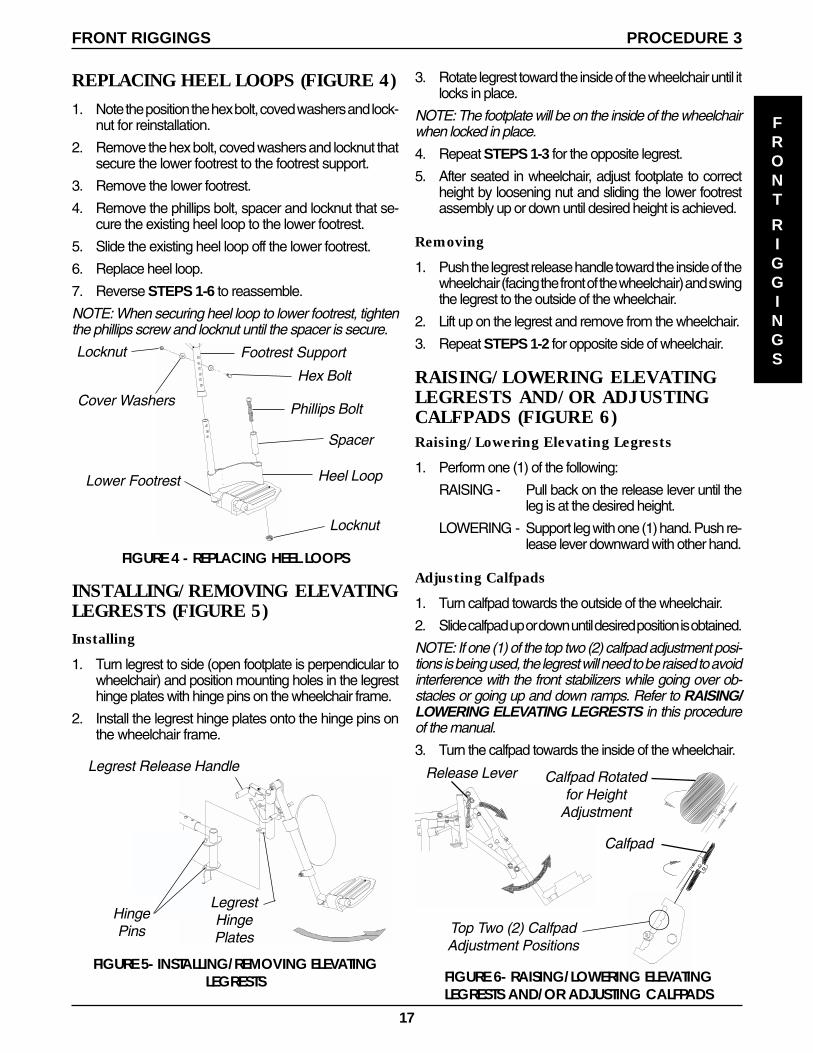
INSTALLING/REMOVING ELEVATINGLEGRESTS (FIGURE 5)Installing
1. Turn legrest to side (open footplate is perpendicular towheelchair) and position mounting holes in the legresthinge plates with hinge pins on the wheelchair frame.
2. Install the legrest hinge plates onto the hinge pins onthe wheelchair frame.
HingePins
LegrestHingePlates
Legrest Release Handle
Phillips Bolt
Spacer
Locknut
Locknut
Heel Loop
FIGURE 4 - REPLACING HEEL LOOPS
Hex Bolt
Cover Washers
Lower Footrest
REPLACING HEEL LOOPS (FIGURE 4)
1. Note the position the hex bolt, coved washers and lock-nut for reinstallation.
2. Remove the hex bolt, coved washers and locknut thatsecure the lower footrest to the footrest support.
3. Remove the lower footrest.
4. Remove the phillips bolt, spacer and locknut that se-cure the existing heel loop to the lower footrest.
5. Slide the existing heel loop off the lower footrest.
6. Replace heel loop.
7. Reverse STEPS 1-6 to reassemble.
NOTE: When securing heel loop to lower footrest, tightenthe phillips screw and locknut until the spacer is secure.
3. Rotate legrest toward the inside of the wheelchair until itlocks in place.
NOTE: The footplate will be on the inside of the wheelchairwhen locked in place.
4. Repeat STEPS 1-3 for the opposite legrest.
5. After seated in wheelchair, adjust footplate to correctheight by loosening nut and sliding the lower footrestassembly up or down until desired height is achieved.
Removing
1. Push the legrest release handle toward the inside of thewheelchair (facing the front of the wheelchair) and swingthe legrest to the outside of the wheelchair.
2. Lift up on the legrest and remove from the wheelchair.
3. Repeat STEPS 1-2 for opposite side of wheelchair.
RAISING/LOWERING ELEVATINGLEGRESTS AND/OR ADJUSTINGCALFPADS (FIGURE 6)Raising/Lowering Elevating Legrests
1. Perform one (1) of the following:
RAISING - Pull back on the release lever until theleg is at the desired height.
LOWERING - Support leg with one (1) hand. Push re-lease lever downward with other hand.
Adjusting Calfpads
1. Turn calfpad towards the outside of the wheelchair.
2. Slide calfpad up or down until desired position is obtained.
NOTE: If one (1) of the top two (2) calfpad adjustment posi-tions is being used, the legrest will need to be raised to avoidinterference with the front stabilizers while going over ob-stacles or going up and down ramps. Refer to RAISING/LOWERING ELEVATING LEGRESTS in this procedureof the manual.
3. Turn the calfpad towards the inside of the wheelchair.
Release Lever
Calfpad
Calfpad Rotatedfor Height
Adjustment
FIGURE 6- RAISING/LOWERING ELEVATINGLEGRESTS AND/OR ADJUSTING CALFPADS
Top Two (2) CalfpadAdjustment Positions
Footrest Support
FRONT
RIGGINGS
FRONT RIGGINGS PROCEDURE 3
18
This Procedure Includes the Following:
Adjusting Armrest Height, Removing or ReplacingArmrests
Adjusting Captain's Seat Armrests
ARMS
ARMSPROCEDURE 4
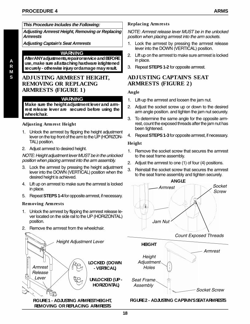
ADJUSTING ARMREST HEIGHT,REMOVING OR REPLACINGARMRESTS (FIGURE 1)
WARNINGMake sure the height adjustment lever and arm-rest release lever are secured before using thewheelchair.
Adjusting Armrest Height
1. Unlock the armrest by flipping the height adjustmentlever on the top front of the arm to the UP (HORIZON-TAL) position.
2. Adjust armrest to desired height.
NOTE: Height adjustment lever MUST be in the unlockedposition when placing armrest into the arm assembly.
3. Lock the armrest by pressing the height adjustmentlever into the DOWN (VERTICAL) position when thedesired height is achieved.
4. Lift up on armrest to make sure the armrest is lockedin place.
5. Repeat STEPS 1-4 for opposite armrest, if necessary.
Removing Armrests
1. Unlock the armrest by flipping the armrest release le-ver located on the side rail to the UP (HORIZONTAL)position.
2. Remove the armrest from the wheelchair.
FIGURE 1 - ADJUSTING ARMREST HEIGHT,REMOVING OR REPLACING ARMRESTS
LOCKED (DOWN- VERTICAL)
UNLOCKED (UP -HORIZONTAL)
Height Adjustment Lever
ArmrestRelease
Lever
WARNINGAfter ANY adjustments, repair or service and BEFOREuse, make sure all attaching hardware is tightenedsecurely - otherwise injury or damage may result.
SocketScrew
ArmrestANGLE
Jam Nut
Count Exposed Threads
Replacing Armrests
NOTE: Armrest release lever MUST be in the unlockedposition when placing armrest into the arm sockets.
1. Lock the armrest by pressing the armrest releaselever into the DOWN (VERTICAL) position.
2. Lift up on the armrest to make sure armrest is lockedin place.
3. Repeat STEPS 1-2 for opposite armrest.
ADJUSTING CAPTAIN'S SEATARMRESTS (FIGURE 2)Angle
1. Lift-up the armrest and loosen the jam nut.
2. Adjust the socket screw up or down to the desiredarm angle position. and tighten the jam nut securely.
3. To determine the same angle for the opposite arm-rest, count the exposed threads after the jam nut hasbeen tightened.
4. Repeat STEPS 1-3 for opposite armrest, if necessary.
Height
1. Remove the socket screw that secures the armrestto the seat frame assembly.
2. Adjust the armrest to one (1) of four (4) positions.
3. Reinstall the socket screw that secures the armrestto the seat frame assembly and tighten securely.
Socket Screw
Seat FrameAssembly
HeightAdjustment
Holes
Armrest
HEIGHT
FIGURE 2 - ADJUSTING CAPTAIN'S SEAT ARMRESTS
19
Seat UpholsteryWasher
Crossbrace
FIGURE 2 - REPLACING SEAT POSITIONING STRAP
Rear Phillips Screw
Seat PositioningStrap
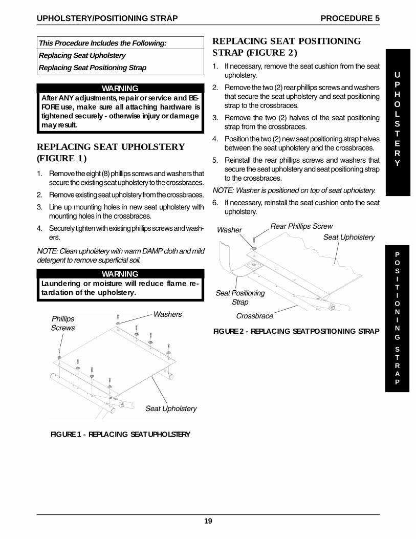
REPLACING SEAT POSITIONINGSTRAP (FIGURE 2)1. If necessary, remove the seat cushion from the seat
upholstery.
2. Remove the two (2) rear phillips screws and washersthat secure the seat upholstery and seat positioningstrap to the crossbraces.
3. Remove the two (2) halves of the seat positioningstrap from the crossbraces.
4. Position the two (2) new seat positioning strap halvesbetween the seat upholstery and the crossbraces.
5. Reinstall the rear phillips screws and washers thatsecure the seat upholstery and seat positioning strapto the crossbraces.
NOTE: Washer is positioned on top of seat upholstery.
6. If necessary, reinstall the seat cushion onto the seatupholstery.
UPHOLSTERY
PROCEDURE 5UPHOLSTERY/POSITIONING STRAP
This Procedure Includes the Following:
Replacing Seat Upholstery
Replacing Seat Positioning Strap
REPLACING SEAT UPHOLSTERY(FIGURE 1)
1. Remove the eight (8) phillips screws and washers thatsecure the existing seat upholstery to the crossbraces.
2. Remove existing seat upholstery from the crossbraces.
3. Line up mounting holes in new seat upholstery withmounting holes in the crossbraces.
4. Securely tighten with existing phillips screws and wash-ers.
NOTE: Clean upholstery with warm DAMP cloth and milddetergent to remove superficial soil.
WARNINGLaundering or moisture will reduce flame re-tardation of the upholstery.
FIGURE 1 - REPLACING SEAT UPHOLSTERY
Seat Upholstery
PhillipsScrews
POSITIONING
STRAP
WARNINGAfter ANY adjustments, repair or service and BE-FORE use, make sure all attaching hardware istightened securely - otherwise injury or damagemay result.
Washers
20
ELECTRONICS
PROCEDURE 6 ELECTRONICS
This Procedure Includes the Following:
Preparing MKIV Joystick for Use
Repositioning MKIV Joystick
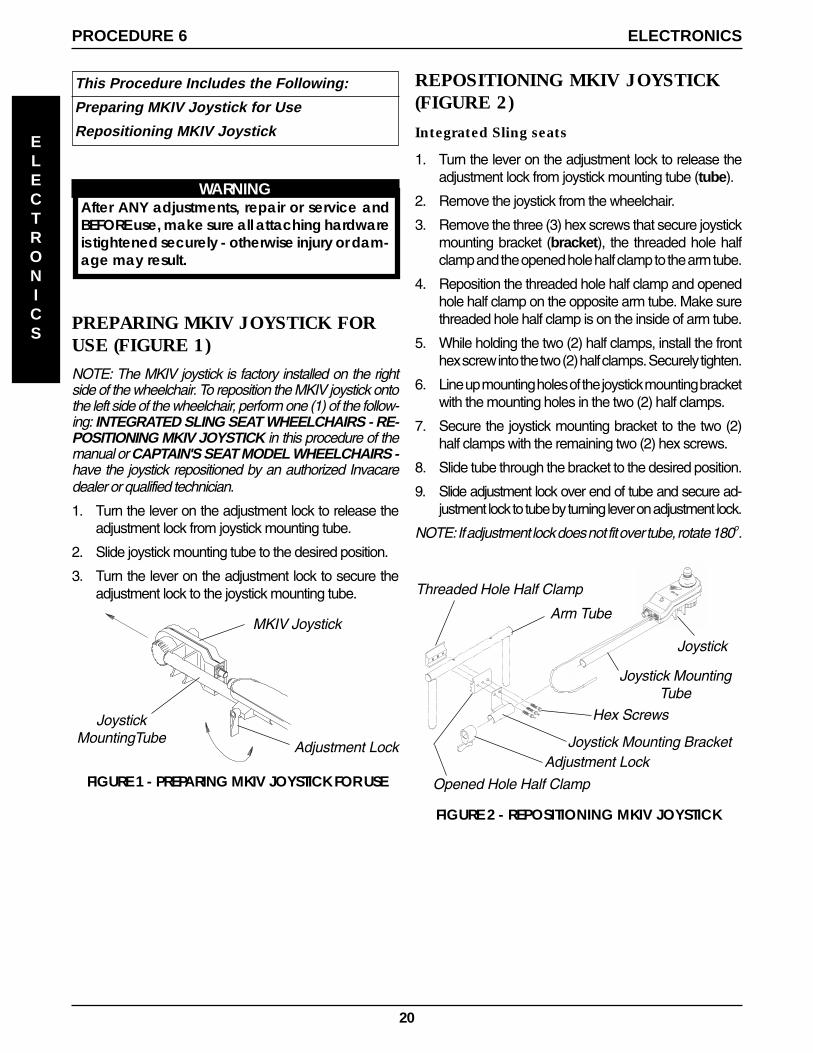
PREPARING MKIV JOYSTICK FORUSE (FIGURE 1)
NOTE: The MKIV joystick is factory installed on the rightside of the wheelchair. To reposition the MKIV joystick ontothe left side of the wheelchair, perform one (1) of the follow-ing: INTEGRATED SLING SEAT WHEELCHAIRS - RE-POSITIONING MKIV JOYSTICK in this procedure of themanual or CAPTAIN'S SEAT MODEL WHEELCHAIRS -have the joystick repositioned by an authorized Invacaredealer or qualified technician.
1. Turn the lever on the adjustment lock to release theadjustment lock from joystick mounting tube.
2. Slide joystick mounting tube to the desired position.
3. Turn the lever on the adjustment lock to secure theadjustment lock to the joystick mounting tube.
JoystickMountingTube
FIGURE 1 - PREPARING MKIV JOYSTICK FOR USE
MKIV Joystick
Adjustment Lock
REPOSITIONING MKIV JOYSTICK(FIGURE 2)
Integrated Sling seats
1. Turn the lever on the adjustment lock to release theadjustment lock from joystick mounting tube (tube).
2. Remove the joystick from the wheelchair.
3. Remove the three (3) hex screws that secure joystickmounting bracket (bracket), the threaded hole halfclamp and the opened hole half clamp to the arm tube.
4. Reposition the threaded hole half clamp and openedhole half clamp on the opposite arm tube. Make surethreaded hole half clamp is on the inside of arm tube.
5. While holding the two (2) half clamps, install the fronthex screw into the two (2) half clamps. Securely tighten.
6. Line up mounting holes of the joystick mounting bracketwith the mounting holes in the two (2) half clamps.
7. Secure the joystick mounting bracket to the two (2)half clamps with the remaining two (2) hex screws.
8. Slide tube through the bracket to the desired position.
9. Slide adjustment lock over end of tube and secure ad-justment lock to tube by turning lever on adjustment lock.
NOTE: If adjustment lock does not fit over tube, rotate 180o.
Threaded Hole Half Clamp
Joystick MountingTube
Hex Screws
Joystick Mounting BracketAdjustment Lock
Arm Tube
Joystick
Opened Hole Half Clamp
FIGURE 2 - REPOSITIONING MKIV JOYSTICK
WARNINGAfter ANY adjustments, repair or service andBEFORE use, make sure all attaching hardwareis tightened securely - otherwise injury or dam-age may result.
21
This Procedure Includes the Following:
Replacing Battery Box Retaining Strap RETAINING
STRAP
PROCEDURE 7RETAINING STRAP
WARNINGAfter ANY adjustments, repair or service and BEFOREuse, make sure all attaching hardware is tightenedsecurely - otherwise injury or damage may result.
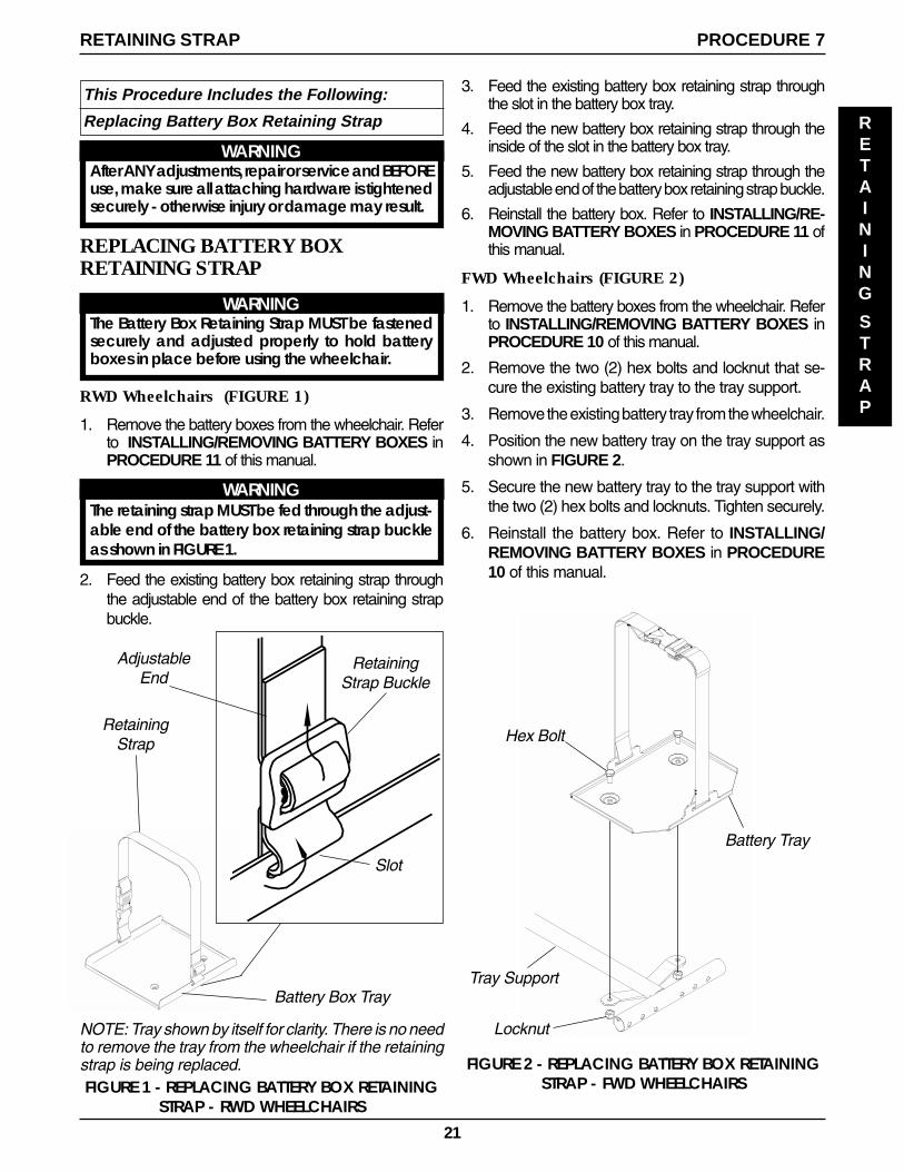
NOTE: Tray shown by itself for clarity. There is no needto remove the tray from the wheelchair if the retainingstrap is being replaced.FIGURE 1 - REPLACING BATTERY BOX RETAINING
STRAP - RWD WHEELCHAIRS
Slot
Battery Box Tray
RetainingStrap
RetainingStrap Buckle
AdjustableEnd
REPLACING BATTERY BOXRETAINING STRAP
WARNINGThe Battery Box Retaining Strap MUST be fastenedsecurely and adjusted properly to hold batteryboxes in place before using the wheelchair.
RWD Wheelchairs (FIGURE 1)
1. Remove the battery boxes from the wheelchair. Referto INSTALLING/REMOVING BATTERY BOXES inPROCEDURE 11 of this manual.
WARNINGThe retaining strap MUST be fed through the adjust-able end of the battery box retaining strap buckleas shown in FIGURE 1.
2. Feed the existing battery box retaining strap throughthe adjustable end of the battery box retaining strapbuckle.
3. Feed the existing battery box retaining strap throughthe slot in the battery box tray.
4. Feed the new battery box retaining strap through theinside of the slot in the battery box tray.
5. Feed the new battery box retaining strap through theadjustable end of the battery box retaining strap buckle.
6. Reinstall the battery box. Refer to INSTALLING/RE-MOVING BATTERY BOXES in PROCEDURE 11 ofthis manual.
FWD Wheelchairs (FIGURE 2)
1. Remove the battery boxes from the wheelchair. Referto INSTALLING/REMOVING BATTERY BOXES inPROCEDURE 10 of this manual.
2. Remove the two (2) hex bolts and locknut that se-cure the existing battery tray to the tray support.
3. Remove the existing battery tray from the wheelchair.
4. Position the new battery tray on the tray support asshown in FIGURE 2.
5. Secure the new battery tray to the tray support withthe two (2) hex bolts and locknuts. Tighten securely.
6. Reinstall the battery box. Refer to INSTALLING/REMOVING BATTERY BOXES in PROCEDURE10 of this manual.
FIGURE 2 - REPLACING BATTERY BOX RETAININGSTRAP - FWD WHEELCHAIRS
Battery Tray
Tray Support
Hex Bolt
Locknut
22
CASTERS
PROCEDURE 8 CASTERS
This Procedure Includes the Following:
Adjusting Forks
WARNINGAfter ANY adjustments, repair or service and BE-FORE use, make sure all attaching hardware istightened securely - otherwise injury or damagemay result.
CAUTIONAs with any vehicle, the wheels and tires shouldbe checked periodically for cracks and wearand should be replaced when necessary.
Dust Cover
Locknut
Nylon Washer
Fork
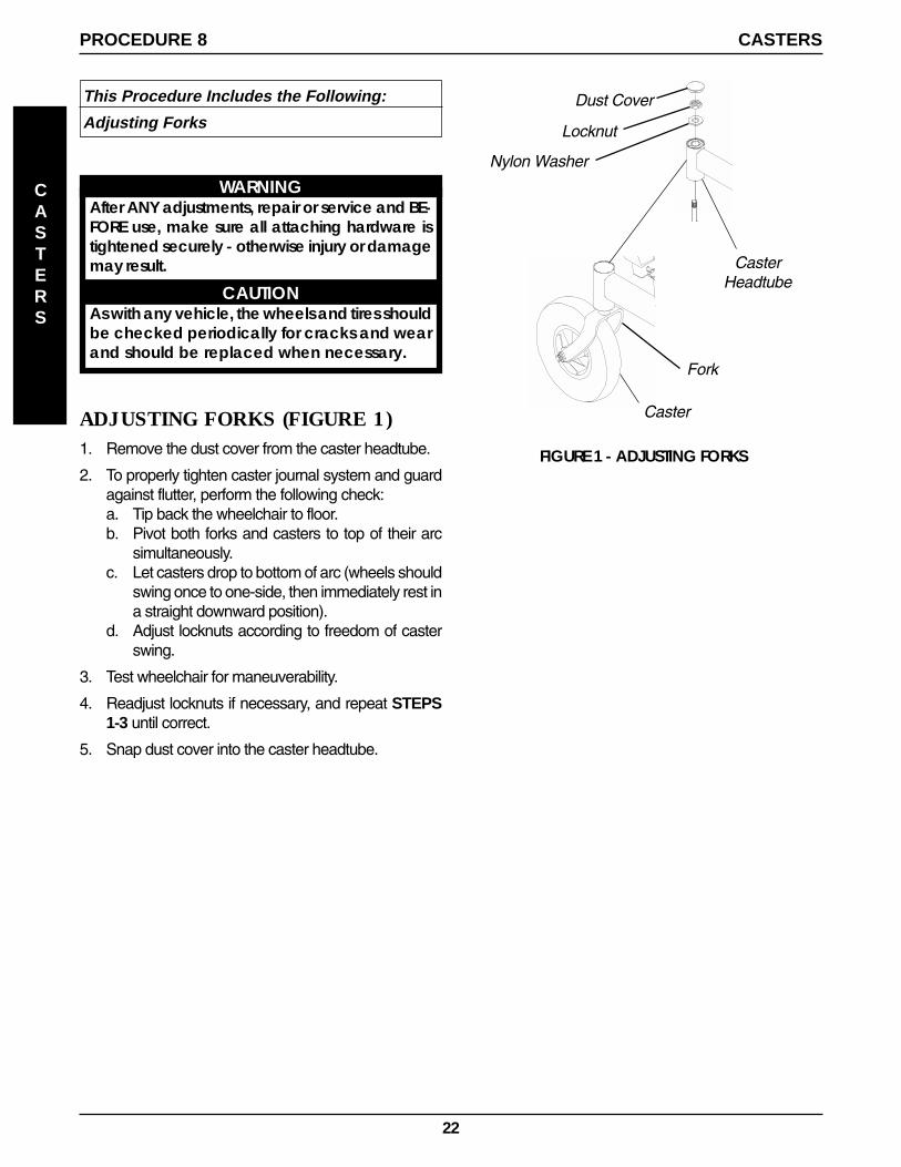
ADJUSTING FORKS (FIGURE 1)1. Remove the dust cover from the caster headtube.
2. To properly tighten caster journal system and guardagainst flutter, perform the following check:a. Tip back the wheelchair to floor.b. Pivot both forks and casters to top of their arc
simultaneously.c. Let casters drop to bottom of arc (wheels should
swing once to one-side, then immediately rest ina straight downward position).
d. Adjust locknuts according to freedom of casterswing.
3. Test wheelchair for maneuverability.
4. Readjust locknuts if necessary, and repeat STEPS1-3 until correct.
5. Snap dust cover into the caster headtube.
FIGURE 1 - ADJUSTING FORKS
Caster
CasterHeadtube
23
PROCEDURE 9BATTERIES
BATTERIES
This Procedure includes the following:
Installing/Removing Batteries into/From BatteryBoxes
Connecting Battery Cables
WARNINGMake sure power to the wheelchair is OFF be-fore performing this procedure.
The use of rubber gloves and safety glasses is rec-ommended when working with batteries.Invacare strongly recommends that battery in-stallation and battery replacement ALWAYS bedone by a qualified technician.After ANY adjustments, repair or service and BE-FORE use, make sure all attaching hardware istightened securely - otherwise injury or damagemay result.
NOTE: For CHANGING or REMOVING/INSTALLINGTHE BATTERY BOXES, refer to PROCEDURE 10 - FWDwheelchairs or PROCEDURE 11 - RWD wheelchairs.
INSTALLING/REMOVINGBATTERIES INTO/FROM BATTERYBOXES (FIGURE 1)NOTE: To remove the battery(ies) from the battery box(es),reverse the following procedure.
NOTE: Have the following tools available:
TOOL QTY COMMENTS
Battery Lifting Strap 1 See Note1/2-inch (6 pt) Box Wrench 1 Not Supplied7/16-inch (6pt) Box Wrench 1 Not Supplied3/8-inch (6pt) Box Wrench 1 Not SuppliedDiagonal Cutters 1 Not Supplied
*NOTE: The Battery Lifting strap supplied is for Group22 Batteries ONLY. Refer to the battery manufacturerfor the proper lifting strap and/or battery tools for U1battery removal/installation.
WARNINGALWAYS use a battery lifting strap when lifting abattery. It is the most convenient method andassures that the battery acid will not spill. It alsohelps to prolong the life of the battery.DO NOT tip the batteries. Keep the batteries inan upright position.
NOTE: If there is battery acid in the bottom or on thesides of the battery box(es) or battery(ies), apply bakingsoda to these areas to neutralize the battery acid. Be-fore reinstalling the NEW or existing battery(ies), cleanthe baking soda from the battery box(es) or battery(ies).
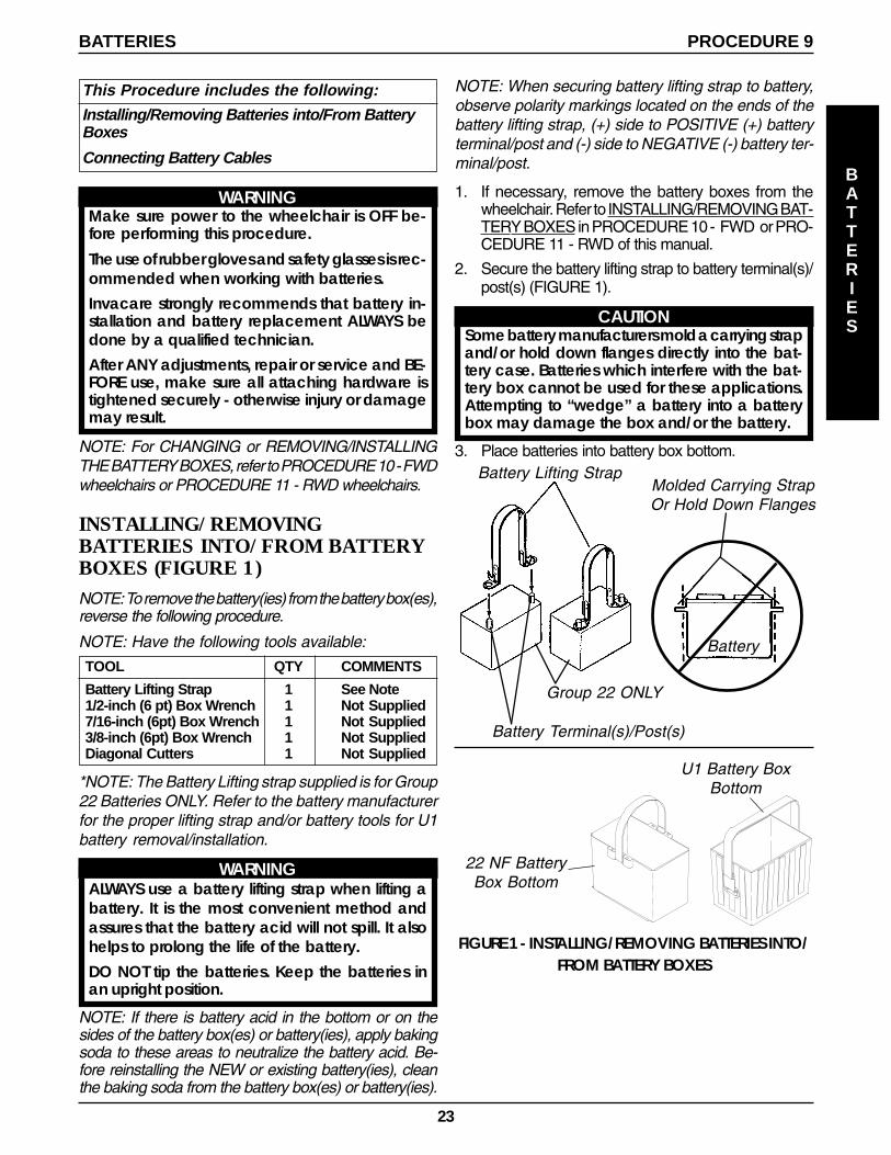
FIGURE 1 - INSTALLING/REMOVING BATTERIES INTO/FROM BATTERY BOXES
Battery Lifting Strap
22 NF BatteryBox Bottom
U1 Battery BoxBottom
Molded Carrying StrapOr Hold Down Flanges
Battery Terminal(s)/Post(s)
NOTE: When securing battery lifting strap to battery,observe polarity markings located on the ends of thebattery lifting strap, (+) side to POSITIVE (+) batteryterminal/post and (-) side to NEGATIVE (-) battery ter-minal/post.
1. If necessary, remove the battery boxes from thewheelchair. Refer to INSTALLING/REMOVING BAT-TERY BOXES in PROCEDURE 10 - FWD or PRO-CEDURE 11 - RWD of this manual.
2. Secure the battery lifting strap to battery terminal(s)/post(s) (FIGURE 1).
CAUTIONSome battery manufacturers mold a carrying strapand/or hold down flanges directly into the bat-tery case. Batteries which interfere with the bat-tery box cannot be used for these applications.Attempting to “wedge” a battery into a batterybox may damage the box and/or the battery.
3. Place batteries into battery box bottom.
Group 22 ONLY
Battery
24
PROCEDURE 9 BATTERIES
BATTERIES
CONNECTING BATTERY CABLES
WARNINGNEVER allow any of your tools and/or batterycable(s) to contact BOTH battery terminal(s)/post(s)at the same time. An electrical short may occurand serious personal injury or damage may occur.
The use of rubber gloves and safety glasses is rec-ommended when working with batteries.
Dual U1 or Dual Group 22 Battery Boxes
Perform one (1) of the following methods for connectingthe battery cable(s):
A. FOR DUAL U1 BATTERIES - Use direct mountmethod. Refer to FIGURES 2, and 3.
B. FOR DUAL GROUP 22 NF BATTERIES THATHAVE MOUNTING HOLES IN THE BATTERYTERMINAL(S)/POST(S) - Use direct mountmethod. Refer to FIGURES 2 AND 3.
C. FOR DUAL GROUP 22 NF BATTERIES THATDO NOT HAVE MOUNTING HOLES IN THEBATTERY TERMINAL(S)/POST(S) - Use batteryclamp method. Refer to FIGURES 4, 5 AND 6.
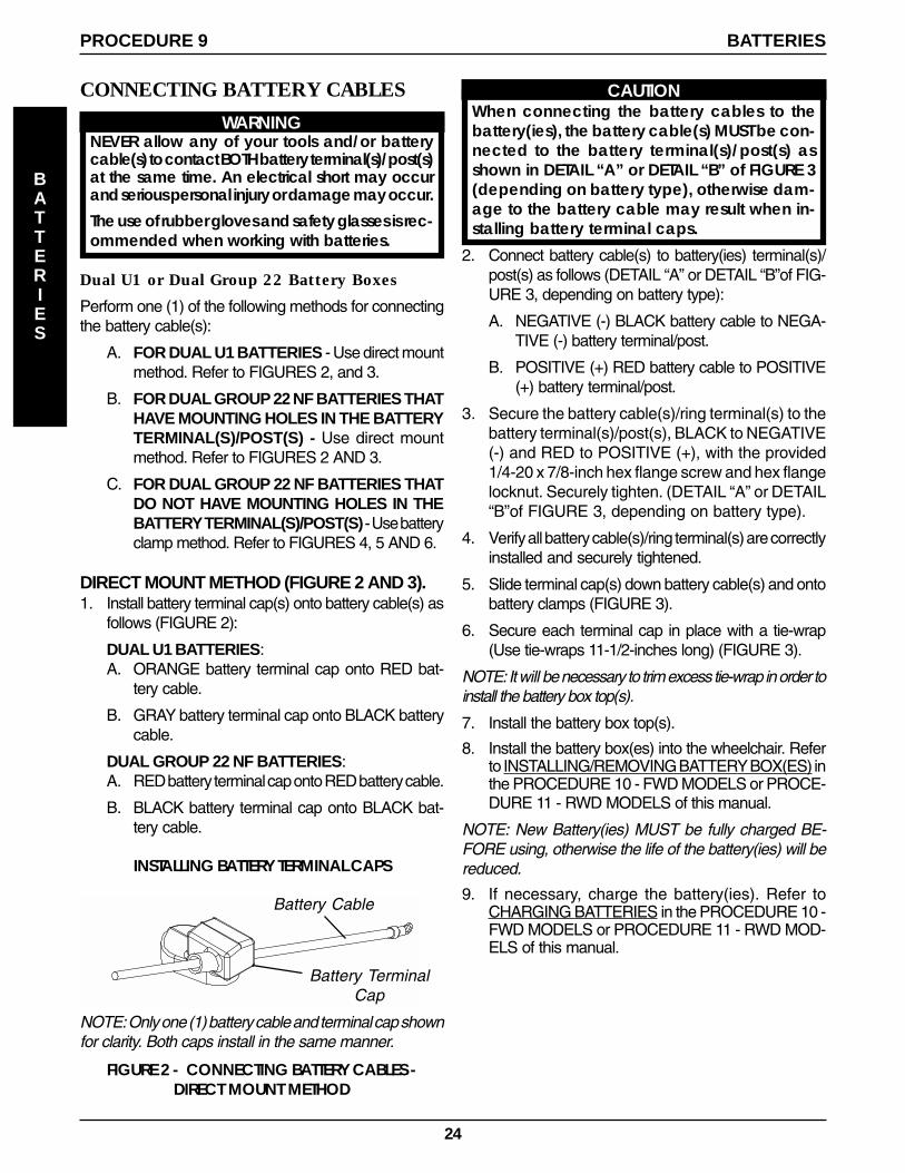
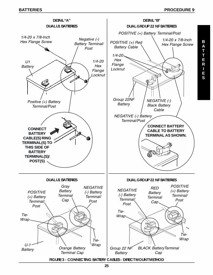
DIRECT MOUNT METHOD (FIGURE 2 AND 3).1. Install battery terminal cap(s) onto battery cable(s) as
follows (FIGURE 2):
DUAL U1 BATTERIES:A. ORANGE battery terminal cap onto RED bat-
tery cable.
B. GRAY battery terminal cap onto BLACK batterycable.
DUAL GROUP 22 NF BATTERIES:A. RED battery terminal cap onto RED battery cable.
B. BLACK battery terminal cap onto BLACK bat-tery cable.
FIGURE 2 - CONNECTING BATTERY CABLES -DIRECT MOUNT METHOD
CAUTIONWhen connecting the battery cables to thebattery(ies), the battery cable(s) MUST be con-nected to the battery terminal(s)/post(s) asshown in DETAIL “A” or DETAIL “B” of FIGURE 3(depending on battery type), otherwise dam-age to the battery cable may result when in-stalling battery terminal caps.
2. Connect battery cable(s) to battery(ies) terminal(s)/post(s) as follows (DETAIL “A” or DETAIL “B”of FIG-URE 3, depending on battery type):
A. NEGATIVE (-) BLACK battery cable to NEGA-TIVE (-) battery terminal/post.
B. POSITIVE (+) RED battery cable to POSITIVE(+) battery terminal/post.
3. Secure the battery cable(s)/ring terminal(s) to thebattery terminal(s)/post(s), BLACK to NEGATIVE(-) and RED to POSITIVE (+), with the provided1/4-20 x 7/8-inch hex flange screw and hex flangelocknut. Securely tighten. (DETAIL “A” or DETAIL“B”of FIGURE 3, depending on battery type).
4. Verify all battery cable(s)/ring terminal(s) are correctlyinstalled and securely tightened.
5. Slide terminal cap(s) down battery cable(s) and ontobattery clamps (FIGURE 3).
6. Secure each terminal cap in place with a tie-wrap(Use tie-wraps 11-1/2-inches long) (FIGURE 3).
NOTE: It will be necessary to trim excess tie-wrap in order toinstall the battery box top(s).
7. Install the battery box top(s).
8. Install the battery box(es) into the wheelchair. Referto INSTALLING/REMOVING BATTERY BOX(ES) inthe PROCEDURE 10 - FWD MODELS or PROCE-DURE 11 - RWD MODELS of this manual.
NOTE: New Battery(ies) MUST be fully charged BE-FORE using, otherwise the life of the battery(ies) will bereduced.
9. If necessary, charge the battery(ies). Refer toCHARGING BATTERIES in the PROCEDURE 10 -FWD MODELS or PROCEDURE 11 - RWD MOD-ELS of this manual.
Battery Cable
Battery TerminalCap
NOTE: Only one (1) battery cable and terminal cap shownfor clarity. Both caps install in the same manner.
INSTALLING BATTERY TERMINAL CAPS
25
PROCEDURE 9BATTERIES
BATTERIES
FIGURE 3 - CONNECTING BATTERY CABLES - DIRECT MOUNT METHOD
Orange BatteryTerminal Cap
POSITIVE(+) BatteryTerminal/
Post
U-1Battery
GrayBattery
TerminalCap
Tie-Wrap
NEGATIVE(-) BatteryTerminal/
Post
Tie-Wrap
1/4-20Hex
FlangeLocknut
Negative (-)Battery Terminal/
Post
1/4-20 x 7/8-Inch Hex Flange Screw
Positive (+) BatteryTerminal/Post
U1Battery
1/4-20 x 7/8-Inch Hex Flange Screw
NEGATIVE (-) BatteryTerminal/Post
Group 22NFBattery
POSITIVE (+) Battery Terminal/Post
POSITIVE (+) RedBattery Cable
NEGATIVE (-)Black Battery
Cable
DETAIL “B”
1/4-20Hex
FlangeLocknut
CONNECT BATTERYCABLE TO BATTERY
TERMINAL AS SHOWN.
DUAL U1 BATTERIES
BLACK BatteryTerminalCap
POSITIVE(+) BatteryTerminal/
Post
Group 22 NFBattery
REDBattery
TerminalCap
Tie-Wrap
NEGATIVE(-) BatteryTerminal/
Post
Tie-Wrap
DETAIL “A”DUAL GROUP 22 NF BATTERIES
CONNECTBATTERY
CABLE(S) RINGTERMINAL(S) TO
THIS SIDE OFBATTERY
TERMINAL(S)/POST(S)
DUAL U1 BATTERIES DUAL GROUP 22 NF BATTERIES
26
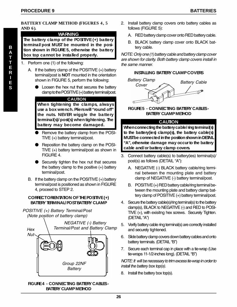
Battery CableBattery ClampCover
2. Install battery clamp covers onto battery cables asfollows (FIGURE 5):
A. RED battery clamp cover onto RED battery cable.
B. BLACK battery clamp cover onto BLACK bat-tery cable.
NOTE: Only one (1) battery cable and battery clamp coverare shown for clarity. Both battery clamp covers install inthe same manner.
BATTERY CLAMP METHOD (FIGURES 4, 5AND 6).
WARNINGThe battery clamp of the POSITIVE (+) batteryterminal/post MUST be mounted in the posi-tion shown in FIGURE 5, otherwise the batterybox top cannot be installed properly.
1. Perform one (1) of the following:
A. If the battery clamp of the POSITIVE (+) batteryterminal/post is NOT mounted in the orientationshown in FIGURE 5, perform the following:
● Loosen the hex nut that secures the batteryclamp to the POSITIVE (+) battery terminal/post.
CAUTIONWhen tightening the clamps, alwaysuse a box wrench. Pliers will “round off”the nuts. NEVER wiggle the batteryterminal(s)/post(s) when tightening. Thebattery may become damaged.
● Remove the battery clamp from the POSI-TIVE (+) battery terminal/post.
● Reposition the battery clamp on the POSI-TIVE (+) battery terminal/post as shown inFIGURE 4.
● Securely tighten the hex nut that securesthe battery clamp to the positive (+) batteryterminal/post.
B. If the battery clamp on the POSITIVE (+) batteryterminal/post is positioned as shown in FIGURE4, proceed to STEP 2.
NEGATIVE (-) BatteryTerminal/Post and Battery Clamp
POSITIVE (+) Battery Terminal/Post(Note position of battery clamp)
FIGURE 4 - CONNECTING BATTERY CABLES -BATTERY CLAMP METHOD
Group 22NFBattery
HexNut
FIGURE 5 - CONNECTING BATTERY CABLES -BATTERY CLAMP METHOD
CAUTIONWhen connecting the battery cable/ring terminal(s)to the battery(ies) clamp(s), the battery cable(s)MUST be connected in the position shown in DETAIL“A”, otherwise damage may occur to the batterycable and/or battery clamp covers.
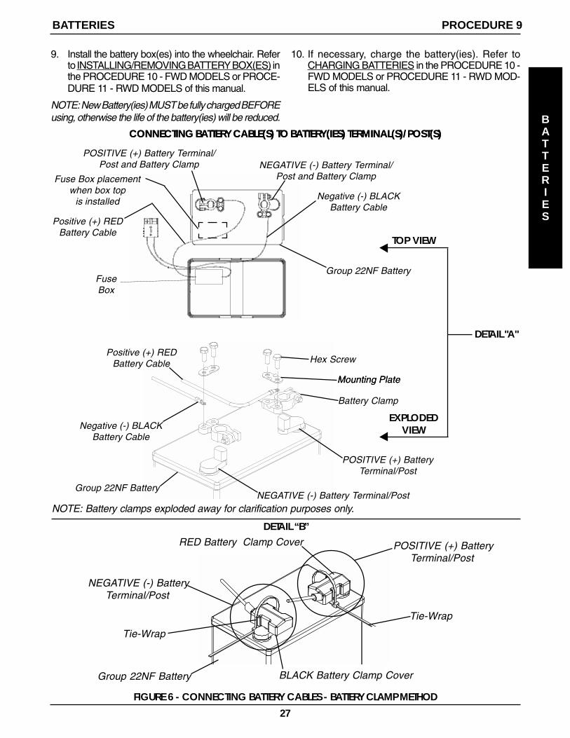
3. Connect battery cable(s) to battery(ies) terminal(s)/post(s) as follows (DETAIL “A”):
A. NEGATIVE (-) BLACK battery cable/ring termi-nal between the mounting plate and batteryclamp of NEGATIVE (-) battery terminal/post.
B. POSITIVE (+) RED battery cable/ring terminal be-tween the mounting plate and battery clamp bat-tery clamp of POSITIVE (+) battery terminal/post.
4. Secure the battery cable(s)/ring terminal(s) to the batteryclamp(s), BLACK to NEGATIVE (-) and RED to POSI-TIVE (+), with exisitng hex screws. Securely Tighten.(DETAIL “A”)
5. Verify battery cable ring terminal(s) are correctly installedand securely tightened.
6. Slide battery clamp covers down battery cables and ontobattery terminals. (DETAIL “B”)
7. Secure each terminal cap in place with a tie-wrap (Usetie-wraps 11-1/2-inches long). (DETAIL “B”)
NOTE: It will be necessary to trim excess tie-wrap in order toinstall the battery box top(s).
8. Install the battery box top(s).
CORRECT ORIENTATION OF THE POSITIVE (+)BATTERY TERMINAL/POST BATTERY CLAMP
INSTALLING BATTERY CLAMP COVERS
PROCEDURE 9 BATTERIES
BATTERIES
27
9. Install the battery box(es) into the wheelchair. Referto INSTALLING/REMOVING BATTERY BOX(ES) inthe PROCEDURE 10 - FWD MODELS or PROCE-DURE 11 - RWD MODELS of this manual.
NOTE: New Battery(ies) MUST be fully charged BEFOREusing, otherwise the life of the battery(ies) will be reduced.
10. If necessary, charge the battery(ies). Refer toCHARGING BATTERIES in the PROCEDURE 10 -FWD MODELS or PROCEDURE 11 - RWD MOD-ELS of this manual.
DETAIL “B”
NOTE: Battery clamps exploded away for clarification purposes only.
Mounting Plate
FIGURE 6 - CONNECTING BATTERY CABLES - BATTERY CLAMP METHOD
CONNECTING BATTERY CABLE(S) TO BATTERY(IES) TERMINAL(S)/POST(S)CONNECTING BATTERY CABLE(S) TO BATTERY(IES) TERMINAL(S)/POST(S)
Hex Screw
Negative (-) BLACKBattery Cable
Positive (+) REDBattery Cable
Battery Clamp
POSITIVE (+) Battery Terminal/Post and Battery Clamp NEGATIVE (-) Battery Terminal/
Post and Battery Clamp
Positive (+) REDBattery Cable
Negative (-) BLACKBattery Cable
Group 22NF Battery
POSITIVE (+) BatteryTerminal/Post
Mounting Plate
Group 22NF BatteryNEGATIVE (-) Battery Terminal/Post
TOP VIEW
EXPLODEDVIEW
RED Battery Clamp Cover
NEGATIVE (-) BatteryTerminal/Post
Tie-Wrap
BLACK Battery Clamp CoverGroup 22NF Battery
Tie-Wrap
POSITIVE (+) BatteryTerminal/Post
PROCEDURE 9BATTERIES
BATTERIES
DETAIL "A"
FuseBox
Fuse Box placementwhen box top
is installed
28
WARNINGAfter ANY adjustments, repair or service and BE-FORE use, make sure all attaching hardware istightened securely - otherwise injury or damagemay result.
This Procedure Includes the Following:
Transporting Excel
Adjusting/Replacing Telescoping Front RiggingSupport
Adjusting Flip-up Removable Footboard
Adjusting Captain's Seat
Removing/Installing Captain's Seat
Disconnecting/Connecting Limit Switch
Removing/Installing Shrouds
Repositioning Battery Charger Connector
When to Charge Batteries
Charging Batteries
Replacing Batteries
Installing/Removing Battery Boxes
Battery Tray
Engaging/Disengaging Clutches
PROCEDURE 10
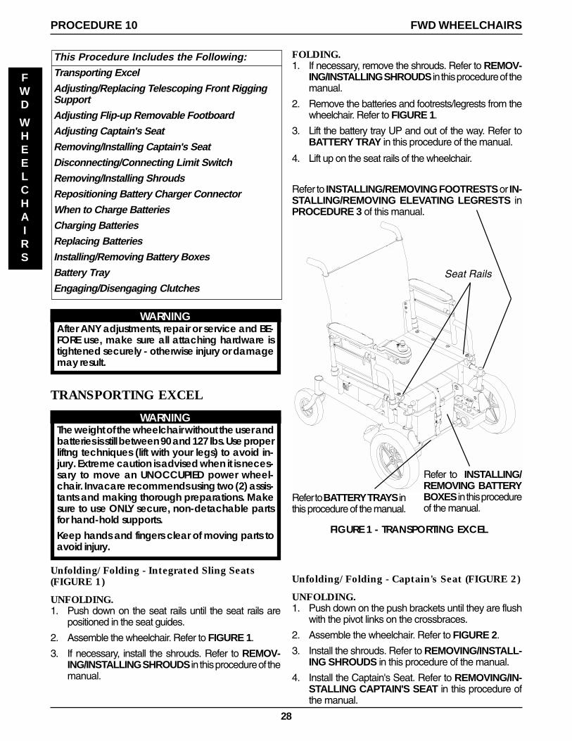
FIGURE 1 - TRANSPORTING EXCEL
FWD WHEELCHAIRS
FWD
WHEELCHAIRS
TRANSPORTING EXCEL
WARNINGThe weight of the wheelchair without the user andbatteries is still between 90 and 127 lbs. Use properliftng techniques (lift with your legs) to avoid in-jury. Extreme caution is advised when it is neces-sary to move an UNOCCUPIED power wheel-chair. Invacare recommends using two (2) assis-tants and making thorough preparations. Makesure to use ONLY secure, non-detachable partsfor hand-hold supports.Keep hands and fingers clear of moving parts toavoid injury.
Unfolding/Folding - Integrated Sling Seats(FIGURE 1)
UNFOLDING.1. Push down on the seat rails until the seat rails are
positioned in the seat guides.
2. Assemble the wheelchair. Refer to FIGURE 1.
3. If necessary, install the shrouds. Refer to REMOV-ING/INSTALLING SHROUDS in this procedure of themanual.
Refer to INSTALLING/REMOVING FOOTRESTS or IN-STALLING/REMOVING ELEVATING LEGRESTS inPROCEDURE 3 of this manual.
Refer to BATTERY TRAYS inthis procedure of the manual.
Refer to INSTALLING/REMOVING BATTERYBOXES in this procedureof the manual.
Seat Rails
FOLDING.1. If necessary, remove the shrouds. Refer to REMOV-
ING/INSTALLING SHROUDS in this procedure of themanual.
2. Remove the batteries and footrests/legrests from thewheelchair. Refer to FIGURE 1.
3. Lift the battery tray UP and out of the way. Refer toBATTERY TRAY in this procedure of the manual.
4. Lift up on the seat rails of the wheelchair.
Unfolding/Folding - Captain's Seat (FIGURE 2)
UNFOLDING.1. Push down on the push brackets until they are flush
with the pivot links on the crossbraces.
2. Assemble the wheelchair. Refer to FIGURE 2.
3. Install the shrouds. Refer to REMOVING/INSTALL-ING SHROUDS in this procedure of the manual.
4. Install the Captain's Seat. Refer to REMOVING/IN-STALLING CAPTAIN'S SEAT in this procedure ofthe manual.
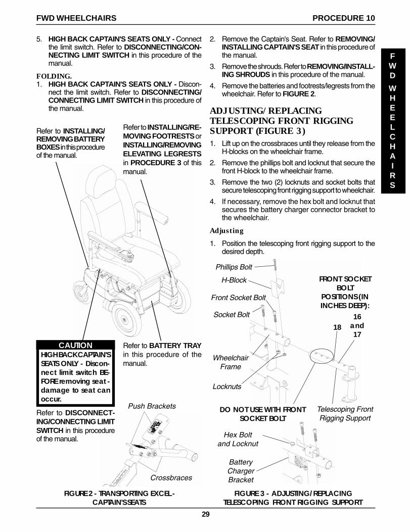
29
PROCEDURE 10FWD WHEELCHAIRS
FWD
WHEELCHAIRS
Refer to INSTALLING/REMOVING BATTERYBOXES in this procedureof the manual.
FIGURE 2 - TRANSPORTING EXCEL -CAPTAIN'S SEATS
Refer to INSTALLING/RE-MOVING FOOTRESTS orINSTALLING/REMOVINGELEVATING LEGRESTSin PROCEDURE 3 of thismanual.
CAUTIONHIGH BACK CAPTAIN'SSEATS ONLY - Discon-nect limit switch BE-FORE removing seat -damage to seat canoccur.
Refer to DISCONNECT-ING/CONNECTING LIMITSWITCH in this procedureof the manual.
Refer to BATTERY TRAYin this procedure of themanual.
Push Brackets
Crossbraces
2. Remove the Captain's Seat. Refer to REMOVING/INSTALLING CAPTAIN'S SEAT in this procedure ofthe manual.
3. Remove the shrouds. Refer to REMOVING/INSTALL-ING SHROUDS in this procedure of the manual.
4. Remove the batteries and footrests/legrests from thewheelchair. Refer to FIGURE 2.
ADJUSTING/REPLACINGTELESCOPING FRONT RIGGINGSUPPORT (FIGURE 3)1. Lift up on the crossbraces until they release from the
H-blocks on the wheelchair frame.
2. Remove the phillips bolt and locknut that secure thefront H-block to the wheelchair frame.
3. Remove the two (2) locknuts and socket bolts thatsecure telescoping front rigging support to wheelchair.
4. If necessary, remove the hex bolt and locknut thatsecures the battery charger connector bracket tothe wheelchair.
Adjusting
1. Position the telescoping front rigging support to thedesired depth.
5. HIGH BACK CAPTAIN'S SEATS ONLY - Connectthe limit switch. Refer to DISCONNECTING/CON-NECTING LIMIT SWITCH in this procedure of themanual.
FOLDING.1. HIGH BACK CAPTAIN'S SEATS ONLY - Discon-
nect the limit switch. Refer to DISCONNECTING/CONNECTING LIMIT SWITCH in this procedure ofthe manual.
FIGURE 3 - ADJUSTING/REPLACINGTELESCOPING FRONT RIGGING SUPPORT
WheelchairFrame
Socket Bolt
H-Block
Phillips Bolt
FRONT SOCKETBOLT
POSITIONS (ININCHES DEEP):
Telescoping FrontRigging Support
DO NOT USE WITH FRONTSOCKET BOLT
Locknuts
Front Socket Bolt
1816
and17
BatteryChargerBracket
Hex Boltand Locknut
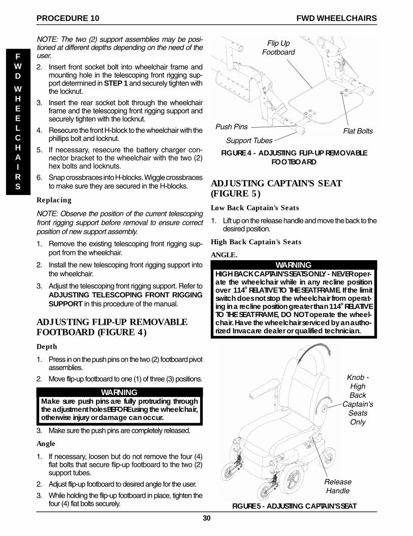
30
NOTE: The two (2) support assemblies may be posi-tioned at different depths depending on the need of theuser.
2. Insert front socket bolt into wheelchair frame andmounting hole in the telescoping front rigging sup-port determined in STEP 1 and securely tighten withthe locknut.
3. Insert the rear socket bolt through the wheelchairframe and the telescoping front rigging support andsecurely tighten with the locknut.
4. Resecure the front H-block to the wheelchair with thephillips bolt and locknut.
5. If necessary, resecure the battery charger con-nector bracket to the wheelchair with the two (2)hex bolts and locknuts.
6. Snap crossbraces into H-blocks. Wiggle crossbracesto make sure they are secured in the H-blocks.
Replacing
NOTE: Observe the position of the current telescopingfront rigging support before removal to ensure correctposition of new support assembly.
1. Remove the existing telescoping front rigging sup-port from the wheelchair.
2. Install the new telescoping front rigging support intothe wheelchair.
3. Adjust the telescoping front rigging support. Refer toADJUSTING TELESCOPING FRONT RIGGINGSUPPORT in this procedure of the manual.
ADJUSTING FLIP-UP REMOVABLEFOOTBOARD (FIGURE 4)Depth
1. Press in on the push pins on the two (2) footboard pivotassemblies.
2. Move flip-up footboard to one (1) of three (3) positions.
WARNINGMake sure push pins are fully protruding throughthe adjustment holes BEFORE using the wheelchair,otherwise injury or damage can occur.
3. Make sure the push pins are completely released.
Angle
1. If necessary, loosen but do not remove the four (4)flat bolts that secure flip-up footboard to the two (2)support tubes.
2. Adjust flip-up footboard to desired angle for the user.
3. While holding the flip-up footboard in place, tighten thefour (4) flat bolts securely.
ADJUSTING CAPTAIN'S SEAT(FIGURE 5)Low Back Captain's Seats
1. Lift up on the release handle and move the back to thedesired position.
High Back Captain's Seats
ANGLE.WARNING
HIGH BACK CAPTAIN'S SEATS ONLY - NEVER oper-ate the wheelchair while in any recline positionover 114o RELATIVE TO THE SEAT FRAME. If the limitswitch does not stop the wheelchair from operat-ing in a recline position greater than 114o RELATIVETO THE SEAT FRAME, DO NOT operate the wheel-chair. Have the wheelchair serviced by an autho-rized Invacare dealer or qualified technician.
ReleaseHandle
Knob -HighBack
Captain'sSeatsOnly
FIGURE 5 - ADJUSTING CAPTAIN'S SEAT
PROCEDURE 10 FWD WHEELCHAIRS
FWD
WHEELCHAIRS
FIGURE 4 - ADJUSTING FLIP-UP REMOVABLEFOOTBOARD
Support Tubes
Flip UpFootboard
Push Pins Flat Bolts

31
1. Lift up on the release handle and move the back to thedesired position.
2. Check the angle of the back RELATIVE TO THE SEATFRAME.
3. If necessary, have the limit switch adjusted. Contactan authorized Invacare dealer or qualified technician.
LUMBAR.1. Rotate the knob on the side of the high back Captain's
Seat COUNTERCLOCKWISE until the desired sup-port is obtained.
NOTE: The knob only rotates COUNTERCLOCKWISE.
REMOVING/INSTALLING CAPTAIN'SSEAT (FIGURE 6)Removing
1. Turn the adjustment lock lever to release the joystickmounting tube from the armrest.
2. Remove the joystick from the wheelchair.
3. HIGH BACK CAPTAIN'S SEATS ONLY - Discon-nect the limit switch. Refer to DISCONNECTING/CONNECTING LIMIT SWITCH in this procedure ofthe manual.
4. Remove the four (4) quick release pins that securethe Captain's Seat to the wheelchair frame.
5. Remove the Captain's Seat from the wheelchair.
Installing
1. Push the Captain's Seat down on the wheelchairframe at the position shown in FIGURE 6.
2. Line up the mounting holes in the Captain's Seat andthe wheelchair frame.
FIGURE 6- REMOVING/INSTALLING CAPTAIN'S SEAT
AdjustmentLock Lever
Quick Release Pins
Captain'sSeat
WheelchairFrame
MountingHoles
JoystickMounting
Tube
ArmrestJoystick
WARNINGMake sure the Captain's Seat is secured to thewheelchair frame with the four (4) quick releasepins BEFORE using the wheelchair, otherwise in-jury or damage can occur.
3. Insert the four (4) quick release pins through themounting holes in the Captain's Seat and the wheel-chair frame until the rings on the quick release pinsare against the mounting holes.
4. Lift up on the Captain's Seat to make sure it is se-cured to the wheelchair frame.
5. HIGH BACK CAPTAIN'S SEATS ONLY - Connectthe limit switch. Refer to DISCONNECTING/CON-NECTING LIMIT SWITCH in this procedure of themanual.
6. Slide the joystick into the adjustment lock lever to thedesired position.
7. Turn the adjustment lock lever to secure the joystickmounting tube to the armrest.
DISCONNECTING/CONNECTINGLIMIT SWITCH (FIGURE 7)NOTE: The following procedure is for High Back Captain'sSeat model wheelchairs only.
CAUTIONDisconnect limit switch BEFORE removing seator damage to switch can occur.
1. Perform one (1) of the following:
DISCONNECTING - While holding body of limitswitch phono plug, lift up gently.
NOTE: When the limit switch is unplugged the wheel-chair will NOT operate.
CONNECTING - Plug limit switch plug into the limitswitch phono jack.
Limit SwitchPhono Plug
Limit SwitchPhono Jack
FIGURE 7 - DISCONNECTING/CONNECTING LIMITSWITCH
PROCEDURE 10FWD WHEELCHAIRS
FWD
WHEELCHAIRS
NOTE: Shroud not shown for clarity.
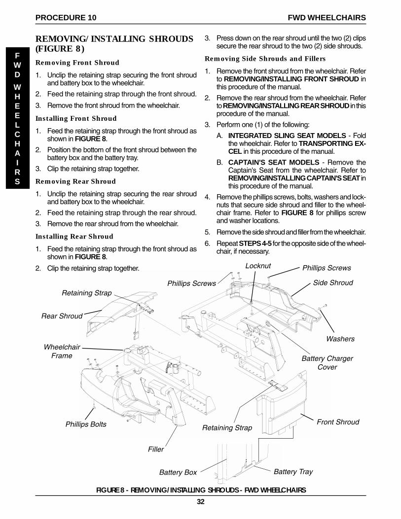
32
REMOVING/INSTALLING SHROUDS(FIGURE 8)Removing Front Shroud
1. Unclip the retaining strap securing the front shroudand battery box to the wheelchair.
2. Feed the retaining strap through the front shroud.
3. Remove the front shroud from the wheelchair.
Installing Front Shroud
1. Feed the retaining strap through the front shroud asshown in FIGURE 8.
2. Position the bottom of the front shroud between thebattery box and the battery tray.
3. Clip the retaining strap together.
Removing Rear Shroud
1. Unclip the retaining strap securing the rear shroudand battery box to the wheelchair.
2. Feed the retaining strap through the rear shroud.
3. Remove the rear shroud from the wheelchair.
Installing Rear Shroud
1. Feed the retaining strap through the front shroud asshown in FIGURE 8.
2. Clip the retaining strap together.
FIGURE 8 - REMOVING/INSTALLING SHROUDS - FWD WHEELCHAIRS
Front Shroud
Phillips Screws
Washers
Rear Shroud
Side Shroud
Phillips Bolts
Locknut
WheelchairFrame
Filler
Retaining Strap
Retaining Strap
Battery Box Battery Tray
Phillips Screws
Battery ChargerCover
3. Press down on the rear shroud until the two (2) clipssecure the rear shroud to the two (2) side shrouds.
Removing Side Shrouds and Fillers
1. Remove the front shroud from the wheelchair. Referto REMOVING/INSTALLING FRONT SHROUD inthis procedure of the manual.
2. Remove the rear shroud from the wheelchair. Referto REMOVING/INSTALLING REAR SHROUD in thisprocedure of the manual.
3. Perform one (1) of the following:
A. INTEGRATED SLING SEAT MODELS - Foldthe wheelchair. Refer to TRANSPORTING EX-CEL in this procedure of the manual.
B. CAPTAIN'S SEAT MODELS - Remove theCaptain's Seat from the wheelchair. Refer toREMOVING/INSTALLING CAPTAIN'S SEAT inthis procedure of the manual.
4. Remove the phillips screws, bolts, washers and lock-nuts that secure side shroud and filler to the wheel-chair frame. Refer to FIGURE 8 for phillips screwand washer locations.
5. Remove the side shroud and filler from the wheelchair.
6. Repeat STEPS 4-5 for the opposite side of the wheel-chair, if necessary.
PROCEDURE 10 FWD WHEELCHAIRS
FWD
WHEELCHAIRS
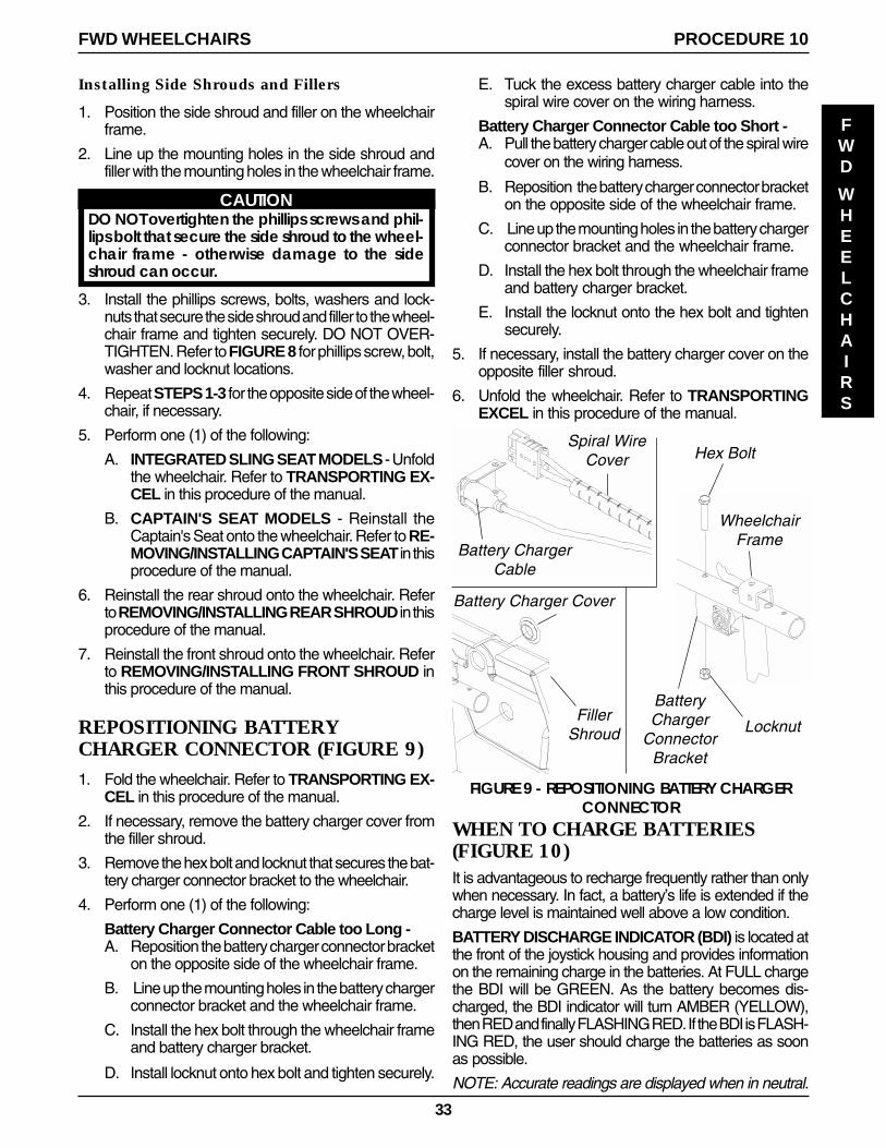
33
Installing Side Shrouds and Fillers
1. Position the side shroud and filler on the wheelchairframe.
2. Line up the mounting holes in the side shroud andfiller with the mounting holes in the wheelchair frame.
CAUTIONDO NOT overtighten the phillips screws and phil-lips bolt that secure the side shroud to the wheel-chair frame - otherwise damage to the sideshroud can occur.
3. Install the phillips screws, bolts, washers and lock-nuts that secure the side shroud and filler to the wheel-chair frame and tighten securely. DO NOT OVER-TIGHTEN. Refer to FIGURE 8 for phillips screw, bolt,washer and locknut locations.
4. Repeat STEPS 1-3 for the opposite side of the wheel-chair, if necessary.
5. Perform one (1) of the following:
A. INTEGRATED SLING SEAT MODELS - Unfoldthe wheelchair. Refer to TRANSPORTING EX-CEL in this procedure of the manual.
B. CAPTAIN'S SEAT MODELS - Reinstall theCaptain's Seat onto the wheelchair. Refer to RE-MOVING/INSTALLING CAPTAIN'S SEAT in thisprocedure of the manual.
6. Reinstall the rear shroud onto the wheelchair. Referto REMOVING/INSTALLING REAR SHROUD in thisprocedure of the manual.
7. Reinstall the front shroud onto the wheelchair. Referto REMOVING/INSTALLING FRONT SHROUD inthis procedure of the manual.
REPOSITIONING BATTERYCHARGER CONNECTOR (FIGURE 9)1. Fold the wheelchair. Refer to TRANSPORTING EX-
CEL in this procedure of the manual.
2. If necessary, remove the battery charger cover fromthe filler shroud.
3. Remove the hex bolt and locknut that secures the bat-tery charger connector bracket to the wheelchair.
4. Perform one (1) of the following:
Battery Charger Connector Cable too Long -A. Reposition the battery charger connector bracket
on the opposite side of the wheelchair frame.
B. Line up the mounting holes in the battery chargerconnector bracket and the wheelchair frame.
C. Install the hex bolt through the wheelchair frameand battery charger bracket.
D. Install locknut onto hex bolt and tighten securely.
E. Tuck the excess battery charger cable into thespiral wire cover on the wiring harness.
Battery Charger Connector Cable too Short -A. Pull the battery charger cable out of the spiral wire
cover on the wiring harness.
B. Reposition the battery charger connector bracketon the opposite side of the wheelchair frame.
C. Line up the mounting holes in the battery chargerconnector bracket and the wheelchair frame.
D. Install the hex bolt through the wheelchair frameand battery charger bracket.
E. Install the locknut onto the hex bolt and tightensecurely.
5. If necessary, install the battery charger cover on theopposite filler shroud.
6. Unfold the wheelchair. Refer to TRANSPORTINGEXCEL in this procedure of the manual.
FIGURE 9 - REPOSITIONING BATTERY CHARGERCONNECTOR
Spiral WireCover
Battery ChargerCable
Hex Bolt
Locknut
WheelchairFrame
BatteryCharger
ConnectorBracket
Battery Charger Cover
FillerShroud
PROCEDURE 10FWD WHEELCHAIRS
FWD
WHEELCHAIRS
WHEN TO CHARGE BATTERIES(FIGURE 10)It is advantageous to recharge frequently rather than onlywhen necessary. In fact, a battery’s life is extended if thecharge level is maintained well above a low condition.
BATTERY DISCHARGE INDICATOR (BDI) is located atthe front of the joystick housing and provides informationon the remaining charge in the batteries. At FULL chargethe BDI will be GREEN. As the battery becomes dis-charged, the BDI indicator will turn AMBER (YELLOW),then RED and finally FLASHING RED. If the BDI is FLASH-ING RED, the user should charge the batteries as soonas possible.
NOTE: Accurate readings are displayed when in neutral.
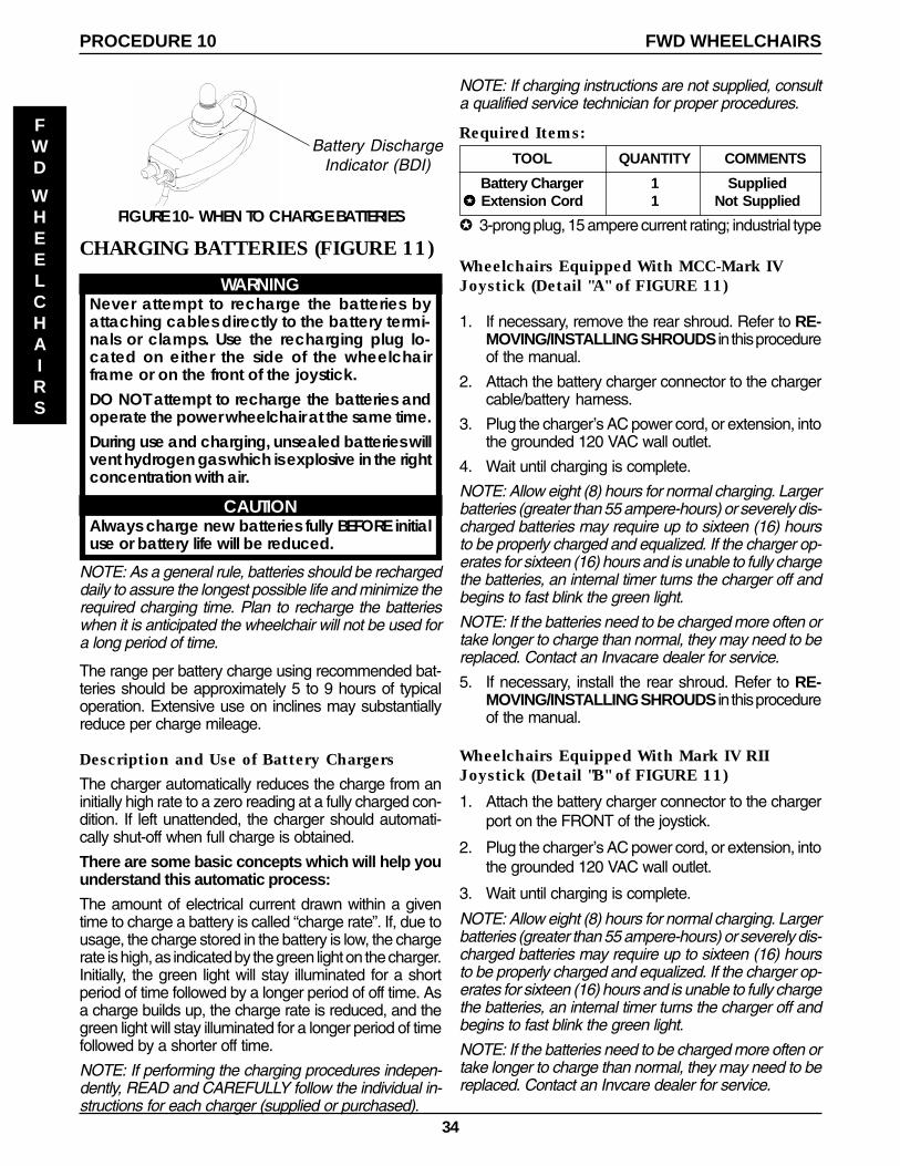
34
FIGURE 10- WHEN TO CHARGE BATTERIES
CHARGING BATTERIES (FIGURE 11)
WARNINGNever attempt to recharge the batteries byattaching cables directly to the battery termi-nals or clamps. Use the recharging plug lo-cated on either the side of the wheelchairframe or on the front of the joystick.DO NOT attempt to recharge the batteries andoperate the power wheelchair at the same time.During use and charging, unsealed batteries willvent hydrogen gas which is explosive in the rightconcentration with air.
CAUTIONAlways charge new batteries fully BEFORE initialuse or battery life will be reduced.
NOTE: As a general rule, batteries should be rechargeddaily to assure the longest possible life and minimize therequired charging time. Plan to recharge the batterieswhen it is anticipated the wheelchair will not be used fora long period of time.
The range per battery charge using recommended bat-teries should be approximately 5 to 9 hours of typicaloperation. Extensive use on inclines may substantiallyreduce per charge mileage.
Description and Use of Battery Chargers
The charger automatically reduces the charge from aninitially high rate to a zero reading at a fully charged con-dition. If left unattended, the charger should automati-cally shut-off when full charge is obtained.
There are some basic concepts which will help youunderstand this automatic process:
The amount of electrical current drawn within a giventime to charge a battery is called “charge rate”. If, due tousage, the charge stored in the battery is low, the chargerate is high, as indicated by the green light on the charger.Initially, the green light will stay illuminated for a shortperiod of time followed by a longer period of off time. Asa charge builds up, the charge rate is reduced, and thegreen light will stay illuminated for a longer period of timefollowed by a shorter off time.
NOTE: If performing the charging procedures indepen-dently, READ and CAREFULLY follow the individual in-structions for each charger (supplied or purchased).
NOTE: If charging instructions are not supplied, consulta qualified service technician for proper procedures.
Required Items:
TOOL QUANTITY COMMENTS
Battery Charger 1 Supplied✪✪✪✪✪ Extension Cord 1 Not Supplied
✪ 3-prong plug, 15 ampere current rating; industrial type
Wheelchairs Equipped With MCC-Mark IVJoystick (Detail "A" of FIGURE 11)
1. If necessary, remove the rear shroud. Refer to RE-MOVING/INSTALLING SHROUDS in this procedureof the manual.
2. Attach the battery charger connector to the chargercable/battery harness.
3. Plug the charger’s AC power cord, or extension, intothe grounded 120 VAC wall outlet.
4. Wait until charging is complete.
NOTE: Allow eight (8) hours for normal charging. Largerbatteries (greater than 55 ampere-hours) or severely dis-charged batteries may require up to sixteen (16) hoursto be properly charged and equalized. If the charger op-erates for sixteen (16) hours and is unable to fully chargethe batteries, an internal timer turns the charger off andbegins to fast blink the green light.
NOTE: If the batteries need to be charged more often ortake longer to charge than normal, they may need to bereplaced. Contact an Invacare dealer for service.
5. If necessary, install the rear shroud. Refer to RE-MOVING/INSTALLING SHROUDS in this procedureof the manual.
Wheelchairs Equipped With Mark IV RIIJoystick (Detail "B" of FIGURE 11)
1. Attach the battery charger connector to the chargerport on the FRONT of the joystick.
2. Plug the charger’s AC power cord, or extension, intothe grounded 120 VAC wall outlet.
3. Wait until charging is complete.
NOTE: Allow eight (8) hours for normal charging. Largerbatteries (greater than 55 ampere-hours) or severely dis-charged batteries may require up to sixteen (16) hoursto be properly charged and equalized. If the charger op-erates for sixteen (16) hours and is unable to fully chargethe batteries, an internal timer turns the charger off andbegins to fast blink the green light.
NOTE: If the batteries need to be charged more often ortake longer to charge than normal, they may need to bereplaced. Contact an Invcare dealer for service.
PROCEDURE 10 FWD WHEELCHAIRS
FWD
WHEELCHAIRS
Battery DischargeIndicator (BDI)
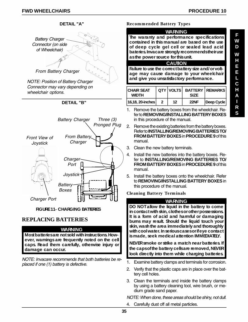
35
FIGURE 11- CHARGING BATTERIES
From Battery Charger
Battery ChargerConnector (on side
of Wheelchair)
NOTE: Position of Battery ChargerConnector may vary depending onwheelchair options.
REPLACING BATTERIES
WARNINGMost batteries are not sold with instructions. How-ever, warnings are frequently noted on the cellcaps. Read them carefully, otherwise injury ordamage can occur.
NOTE: Invacare recommends that both batteries be re-placed if one (1) battery is defective.
DETAIL "A"
DETAIL "B"
Front View ofJoystick
Charger Port
Battery Charger Three (3)Pronged Plug
From BatteryCharger
ChargerPort
Joystick
BatteryBoxes
Recommended Battery Types
WARNINGThe waranty and performance specificationscontained in this manual are based on the useof deep cycle gel cell or sealed lead acidbateries. Invacare strongly recommends their useas the power source for this unit.
CAUTIONFailure to use the correct battery size and/or volt-age may cause damage to your wheelchairand give you unsatisfactory performance.
CHAIR SEAT QTY VOLTS BATTERY REMARKSWIDTH SIZE
16,18, 20-inches 2 12 22NF Deep Cycle
1. Remove the battery boxes from the wheelchair. Re-fer to REMOVING/INSTALLING BATTERY BOXESin this procedure of the manual.
2. Remove the existing batteries from the battery boxes.Refer to INSTALLING/REMOVING BATTERIES TO/FROM BATTERY BOXES in PROCEDURE 9 of thismanual.
3. Clean the new battery terminals.
4. Install the new batteries into the battery boxes. Re-fer to INSTALLING/REMOVING BATTERIES TO/FROM BATTERY BOXES in PROCEDURE 9 of thismanual.
5. Install the battery boxes onto the wheelchair. Referto REMOVING/INSTALLING BATTERY BOXES inthis procedure of the manual.
Cleaning Battery Terminals
WARNINGDO NOT allow the liquid in the battery to comein contact with skin, clothes or other possessions.It is a form of acid and harmful or damagingburns may result. Should the liquid touch yourskin, wash the area immediately and thoroughlywith cool water. In serious cases or if eye contactis made, seek medical attention IMMEDIATELY.
NEVER smoke or strike a match near batteries. Ifthe caps of the battery cells are removed, NEVERlook directly into them while charging batteries.
1. Examine battery clamps and terminals for corrosion.
2. Verify that the plastic caps are in place over the bat-tery cell holes.
3. Clean the terminals and inside the battery clampsby using a battery cleaning tool, wire brush, or me-dium grade sand paper.
NOTE: When done, these areas should be shiny, not dull.
4. Carefully dust off all metal particles.
PROCEDURE 10FWD WHEELCHAIRS
FWD
WHEELCHAIRS
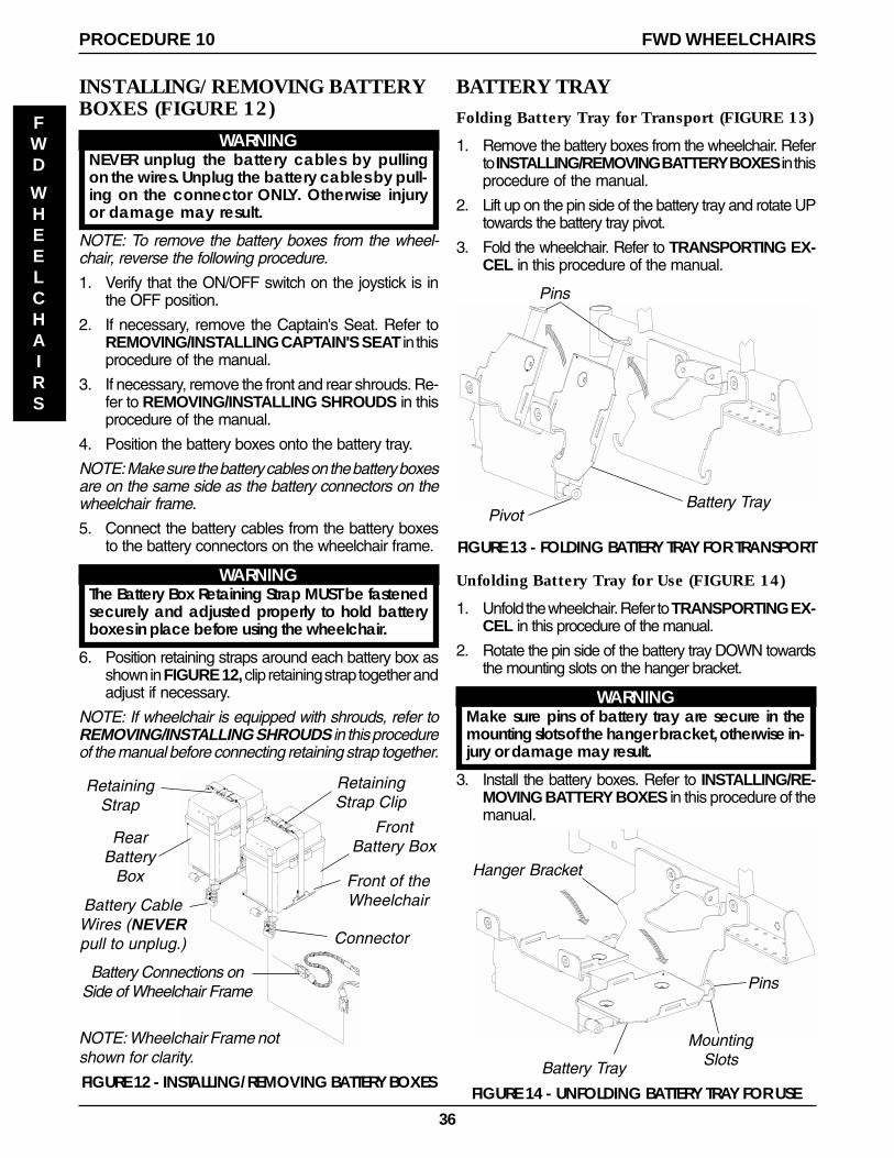
36
BATTERY TRAYFolding Battery Tray for Transport (FIGURE 13)
1. Remove the battery boxes from the wheelchair. Referto INSTALLING/REMOVING BATTERY BOXES in thisprocedure of the manual.
2. Lift up on the pin side of the battery tray and rotate UPtowards the battery tray pivot.
3. Fold the wheelchair. Refer to TRANSPORTING EX-CEL in this procedure of the manual.
Unfolding Battery Tray for Use (FIGURE 14)
1. Unfold the wheelchair. Refer to TRANSPORTING EX-CEL in this procedure of the manual.
2. Rotate the pin side of the battery tray DOWN towardsthe mounting slots on the hanger bracket.
WARNINGMake sure pins of battery tray are secure in themounting slots of the hanger bracket, otherwise in-jury or damage may result.
3. Install the battery boxes. Refer to INSTALLING/RE-MOVING BATTERY BOXES in this procedure of themanual.
FIGURE 13 - FOLDING BATTERY TRAY FOR TRANSPORT
Pins
Battery TrayPivot
MountingSlots
Hanger Bracket
Battery Tray
FIGURE 14 - UNFOLDING BATTERY TRAY FOR USE
Pins
INSTALLING/REMOVING BATTERYBOXES (FIGURE 12)
WARNINGNEVER unplug the battery cables by pullingon the wires. Unplug the battery cables by pull-ing on the connector ONLY. Otherwise injuryor damage may result.
NOTE: To remove the battery boxes from the wheel-chair, reverse the following procedure.
1. Verify that the ON/OFF switch on the joystick is inthe OFF position.
2. If necessary, remove the Captain's Seat. Refer toREMOVING/INSTALLING CAPTAIN'S SEAT in thisprocedure of the manual.
3. If necessary, remove the front and rear shrouds. Re-fer to REMOVING/INSTALLING SHROUDS in thisprocedure of the manual.
4. Position the battery boxes onto the battery tray.
NOTE: Make sure the battery cables on the battery boxesare on the same side as the battery connectors on thewheelchair frame.
5. Connect the battery cables from the battery boxesto the battery connectors on the wheelchair frame.
WARNINGThe Battery Box Retaining Strap MUST be fastenedsecurely and adjusted properly to hold batteryboxes in place before using the wheelchair.
6. Position retaining straps around each battery box asshown in FIGURE 12, clip retaining strap together andadjust if necessary.
NOTE: If wheelchair is equipped with shrouds, refer toREMOVING/INSTALLING SHROUDS in this procedureof the manual before connecting retaining strap together.
RetainingStrap Clip
Battery Connections onSide of Wheelchair Frame
RetainingStrap
NOTE: Wheelchair Frame notshown for clarity.
FIGURE 12 - INSTALLING/REMOVING BATTERY BOXES
FrontBattery Box
Front of theWheelchair
RearBattery
Box
Connector
Battery CableWires (NEVERpull to unplug.)
PROCEDURE 10 FWD WHEELCHAIRS
FWD
WHEELCHAIRS
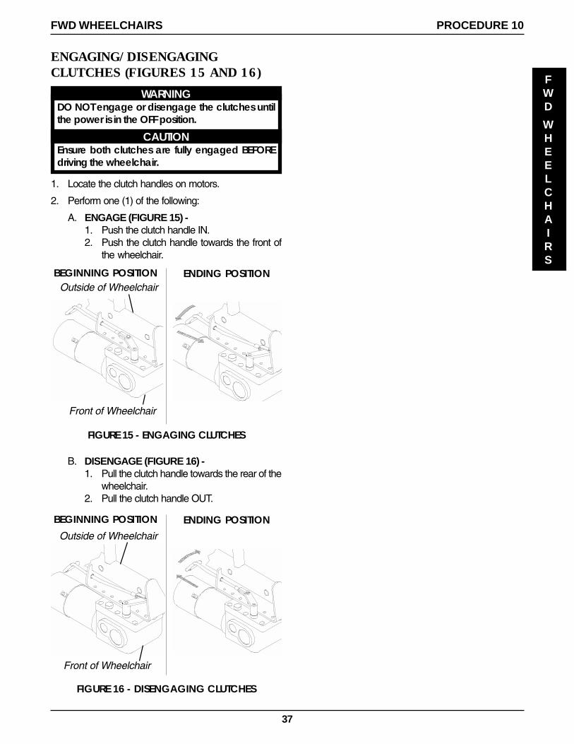
37
ENGAGING/DISENGAGINGCLUTCHES (FIGURES 15 AND 16)
WARNINGDO NOT engage or disengage the clutches untilthe power is in the OFF position.
CAUTIONEnsure both clutches are fully engaged BEFOREdriving the wheelchair.
1. Locate the clutch handles on motors.
2. Perform one (1) of the following:
A. ENGAGE (FIGURE 15) -1. Push the clutch handle IN.2. Push the clutch handle towards the front of
the wheelchair.
BEGINNING POSITION ENDING POSITION
FIGURE 15 - ENGAGING CLUTCHES
Outside of Wheelchair
Front of Wheelchair
FIGURE 16 - DISENGAGING CLUTCHES
BEGINNING POSITION ENDING POSITION
B. DISENGAGE (FIGURE 16) -1. Pull the clutch handle towards the rear of the
wheelchair.2. Pull the clutch handle OUT.
Front of Wheelchair
Outside of Wheelchair
PROCEDURE 10FWD WHEELCHAIRS
FWD
WHEELCHAIRS
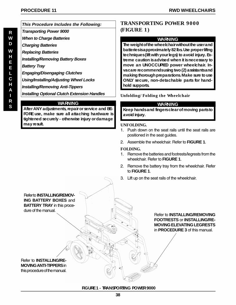
38
This Procedure Includes the Following:
Transporting Power 9000
When to Charge Batteries
Charging Batteries
Replacing Batteries
Installing/Removing Battery Boxes
Battery Tray
Engaging/Disengaging Clutches
Using/Installing/Adjusting Wheel Locks
Installing/Removing Anti-Tippers
Installing Optional Clutch Extension Handles
Refer to INSTALLING/RE-MOVING ANTI-TIPPERS inthis procedure of the manual.
FIGURE 1 - TRANSPORTING POWER 9000
Refer to INSTALLING/REMOVINGFOOTRESTS or INSTALLING/RE-MOVING ELEVATING LEGRESTSin PROCEDURE 3 of this manual.
TRANSPORTING POWER 9000(FIGURE 1)
WARNINGThe weight of the wheelchair without the user andbatteries is approximately 82 lbs. Use proper liftngtechniques (lift with your legs) to avoid injury. Ex-treme caution is advised when it is necessary tomove an UNOCCUPIED power wheelchair. In-vacare recommends using two (2) assistants andmaking thorough preparations. Make sure to useONLY secure, non-detachable parts for hand-hold supports.
Unfolding/Folding the Wheelchair
WARNINGKeep hands and fingers clear of moving parts toavoid injury.
UNFOLDING.1. Push down on the seat rails until the seat rails are
positioned in the seat guides.
2. Assemble the wheelchair. Refer to FIGURE 1.
FOLDING.1. Remove the batteries and footrests/legrests from the
wheelchair. Refer to FIGURE 1.
2. Remove the battery tray from the wheelchair. Referto FIGURE 1.
3. Lift up on the seat rails of the wheelchair.
Refer to INSTALLING/REMOV-ING BATTERY BOXES andBATTERY TRAY in this proce-dure of the manual.
WARNINGAfter ANY adjustments, repair or service and BE-FORE use, make sure all attaching hardware istightened securely - otherwise injury or damagemay result.
PROCEDURE 11 RWD WHEELCHAIRS
RWD
WHEELCHAIRS
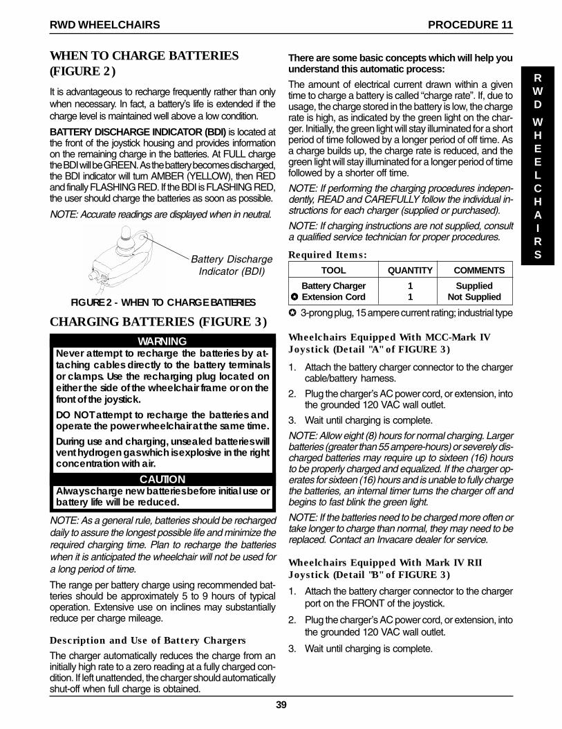
39
Wheelchairs Equipped With MCC-Mark IVJoystick (Detail "A" of FIGURE 3)
1. Attach the battery charger connector to the chargercable/battery harness.
2. Plug the charger’s AC power cord, or extension, intothe grounded 120 VAC wall outlet.
3. Wait until charging is complete.
NOTE: Allow eight (8) hours for normal charging. Largerbatteries (greater than 55 ampere-hours) or severely dis-charged batteries may require up to sixteen (16) hoursto be properly charged and equalized. If the charger op-erates for sixteen (16) hours and is unable to fully chargethe batteries, an internal timer turns the charger off andbegins to fast blink the green light.
NOTE: If the batteries need to be charged more often ortake longer to charge than normal, they may need to bereplaced. Contact an Invacare dealer for service.
Wheelchairs Equipped With Mark IV RIIJoystick (Detail "B" of FIGURE 3)
1. Attach the battery charger connector to the chargerport on the FRONT of the joystick.
2. Plug the charger’s AC power cord, or extension, intothe grounded 120 VAC wall outlet.
3. Wait until charging is complete.
FIGURE 2 - WHEN TO CHARGE BATTERIES
There are some basic concepts which will help youunderstand this automatic process:
The amount of electrical current drawn within a giventime to charge a battery is called “charge rate”. If, due tousage, the charge stored in the battery is low, the chargerate is high, as indicated by the green light on the char-ger. Initially, the green light will stay illuminated for a shortperiod of time followed by a longer period of off time. Asa charge builds up, the charge rate is reduced, and thegreen light will stay illuminated for a longer period of timefollowed by a shorter off time.
NOTE: If performing the charging procedures indepen-dently, READ and CAREFULLY follow the individual in-structions for each charger (supplied or purchased).
NOTE: If charging instructions are not supplied, consulta qualified service technician for proper procedures.
Required Items:
TOOL QUANTITY COMMENTS
Battery Charger 1 Supplied✪✪✪✪✪ Extension Cord 1 Not Supplied
✪ 3-prong plug, 15 ampere current rating; industrial type
WHEN TO CHARGE BATTERIES(FIGURE 2)
It is advantageous to recharge frequently rather than onlywhen necessary. In fact, a battery’s life is extended if thecharge level is maintained well above a low condition.
BATTERY DISCHARGE INDICATOR (BDI) is located atthe front of the joystick housing and provides informationon the remaining charge in the batteries. At FULL chargethe BDI will be GREEN. As the battery becomes discharged,the BDI indicator will turn AMBER (YELLOW), then REDand finally FLASHING RED. If the BDI is FLASHING RED,the user should charge the batteries as soon as possible.
NOTE: Accurate readings are displayed when in neutral.
PROCEDURE 11RWD WHEELCHAIRS
RWD
WHEELCHAIRS
CHARGING BATTERIES (FIGURE 3)
WARNINGNever attempt to recharge the batteries by at-taching cables directly to the battery terminalsor clamps. Use the recharging plug located oneither the side of the wheelchair frame or on thefront of the joystick.DO NOT attempt to recharge the batteries andoperate the power wheelchair at the same time.During use and charging, unsealed batteries willvent hydrogen gas which is explosive in the rightconcentration with air.
CAUTIONAlways charge new batteries before initial use orbattery life will be reduced.
NOTE: As a general rule, batteries should be rechargeddaily to assure the longest possible life and minimize therequired charging time. Plan to recharge the batterieswhen it is anticipated the wheelchair will not be used fora long period of time.
The range per battery charge using recommended bat-teries should be approximately 5 to 9 hours of typicaloperation. Extensive use on inclines may substantiallyreduce per charge mileage.
Description and Use of Battery Chargers
The charger automatically reduces the charge from aninitially high rate to a zero reading at a fully charged con-dition. If left unattended, the charger should automaticallyshut-off when full charge is obtained.
Battery DischargeIndicator (BDI)
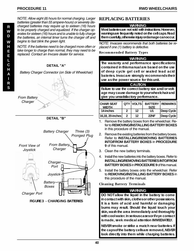
40
REPLACING BATTERIES
WARNINGMost batteries are not sold with instructions. However,warnings are frequently noted on the cell caps. Readthem carefully, otherwise injury or damage can occur.
NOTE: Invacare recommends that both batteries be re-placed if one (1) battery is defective.
Recommended Battery Types
WARNINGThe waranty and performance specificationscontained in this manual are based on the useof deep cycle gel cell or sealed lead acidbateries. Invacare strongly recommends theiruse as the power source for this unit.
CAUTIONFailure to use the correct battery size and/or volt-age may cause damage to your wheelchair andgive you unsatisfactory performance.
CHAIR SEAT QTY VOLTS BATTERY REMARKSWIDTH SIZE
14-inches 2 12 U1 Deep Cycle
16,18, 20-inches 2 12 22NF Deep Cycle
1. Remove the battery boxes from the wheelchair. Re-fer to REMOVING/INSTALLING BATTERY BOXESin this procedure of the manual.
2. Remove the existing batteries from the battery boxes.Refer to INSTALLING/REMOVING BATTERIESINTO/FROM BATTERY BOXES in PROCEDURE9 of this manual.
3. Clean the new battery terminals.
4. Install the new batteries into the battery boxes. Refer toINSTALLING/REMOVING BATTERIES INTO/FROMBATTERY BOXES in PROCEDURE 9 of this manual.
5. Install the battery boxes onto the wheelchair. Referto REMOVING/INSTALLING BATTERY BOXES inthis procedure of the manual.
Cleaning Battery Terminals
WARNINGDO NOT allow the liquid in the battery to comein contact with skin, clothes or other possessions.It is a form of acid and harmful or damagingburns may result. Should the liquid touch yourskin, wash the area immediately and thoroughlywith cool water. In serious cases or if eye contactis made, seek medical attention IMMEDIATELY.
NEVER smoke or strike a match near batteries. Ifthe caps of the battery cells are removed, NEVERlook directly into them while charging batteries.
From BatteryCharger
Battery Charger Connector (on Side of Wheelchair)
FIGURE 3 - CHARGING BATTERIES
DETAIL "A"
DETAIL "B"
Front View ofJoystick
Charger Port
Battery Charger Three (3)Pronged Plug
From BatteryCharger
ChargerPort
Joystick
BatteryBoxes
NOTE: Allow eight (8) hours for normal charging. Largerbatteries (greater than 55 ampere-hours) or severely dis-charged batteries may require up to sixteen (16) hoursto be properly charged and equalized. If the charger op-erates for sixteen (16) hours and is unable to fully chargethe batteries, an internal timer turns the charger off andbegins to fast blink the green light.
NOTE: If the batteries need to be charged more often ortake longer to charge than normal, they may need to bereplaced. Contact an Invcare dealer for service.
PROCEDURE 11 RWD WHEELCHAIRS
RWD
WHEELCHAIRS
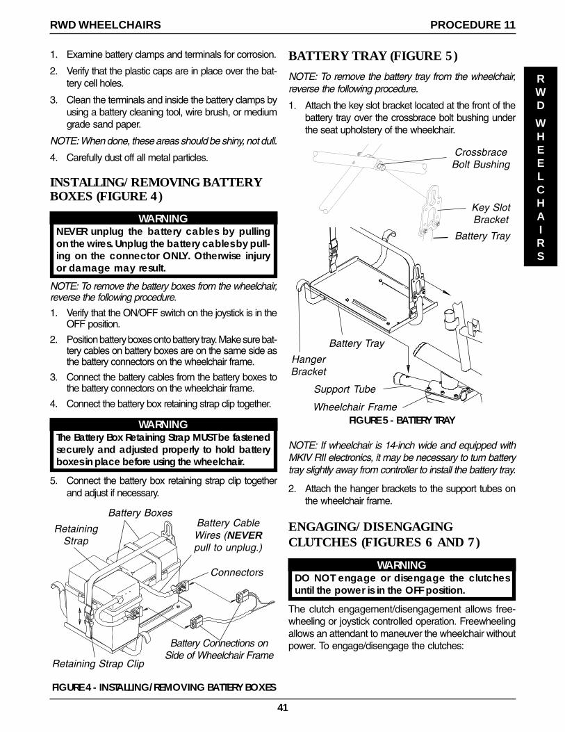
41
1. Examine battery clamps and terminals for corrosion.
2. Verify that the plastic caps are in place over the bat-tery cell holes.
3. Clean the terminals and inside the battery clamps byusing a battery cleaning tool, wire brush, or mediumgrade sand paper.
NOTE: When done, these areas should be shiny, not dull.
4. Carefully dust off all metal particles.
INSTALLING/REMOVING BATTERYBOXES (FIGURE 4)
WARNINGNEVER unplug the battery cables by pullingon the wires. Unplug the battery cables by pull-ing on the connector ONLY. Otherwise injuryor damage may result.
NOTE: To remove the battery boxes from the wheelchair,reverse the following procedure.
1. Verify that the ON/OFF switch on the joystick is in theOFF position.
2. Position battery boxes onto battery tray. Make sure bat-tery cables on battery boxes are on the same side asthe battery connectors on the wheelchair frame.
3. Connect the battery cables from the battery boxes tothe battery connectors on the wheelchair frame.
4. Connect the battery box retaining strap clip together.
WARNINGThe Battery Box Retaining Strap MUST be fastenedsecurely and adjusted properly to hold batteryboxes in place before using the wheelchair.
5. Connect the battery box retaining strap clip togetherand adjust if necessary.
PROCEDURE 11RWD WHEELCHAIRS
RWD
WHEELCHAIRS
Retaining Strap Clip
Battery Connections onSide of Wheelchair Frame
RetainingStrap
FIGURE 4 - INSTALLING/REMOVING BATTERY BOXES
Battery Boxes
Connectors
Battery CableWires (NEVERpull to unplug.)
BATTERY TRAY (FIGURE 5)
NOTE: To remove the battery tray from the wheelchair,reverse the following procedure.
1. Attach the key slot bracket located at the front of thebattery tray over the crossbrace bolt bushing underthe seat upholstery of the wheelchair.
Battery Tray
HangerBracket
Support Tube
CrossbraceBolt Bushing
Battery Tray
Key SlotBracket
FIGURE 5 - BATTERY TRAY
NOTE: If wheelchair is 14-inch wide and equipped withMKIV RII electronics, it may be necessary to turn batterytray slightly away from controller to install the battery tray.
2. Attach the hanger brackets to the support tubes onthe wheelchair frame.
ENGAGING/DISENGAGINGCLUTCHES (FIGURES 6 AND 7)
WARNINGDO NOT engage or disengage the clutchesuntil the power is in the OFF position.
The clutch engagement/disengagement allows free-wheeling or joystick controlled operation. Freewheelingallows an attendant to maneuver the wheelchair withoutpower. To engage/disengage the clutches:
Wheelchair Frame
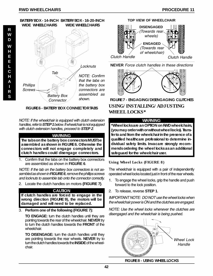
42
FIGURE 8 - USING WHEEL LOCKS
Wheel LockHandle
Clutch Handle
FIGURE 7 - ENGAGING/DISENGAGING CLUTCHES
NEVER Force clutch handles in these directions
ENGAGED(Towards rearof wheelchair)
Clutch Handle
DISENGAGED(Towards rear
wheels)
TOP VIEW OF WHEELCHAIR
USING/INSTALLING/ADJUSTINGWHEEL LOCKS*
WARNING*Wheel locks are an OPTION on RWD wheelchairs,(you may order with or without wheel locks). Trans-fer to and from the wheelchair in the presence of aqualified healthcare professional to determine in-dividual safety limits. Invacare strongly recom-mends ordering the wheel locks as an additionalsafeguard for the wheelchair user.
Using Wheel Locks (FIGURE 8)
The wheelchair is equipped with a pair of independentlyoperated wheel locks located just in front of the rear wheels.
1. To engage the wheel locks, grip the handle and pushforward to the lock position.
2. To release, reverse STEP 1.
IMPORTANT NOTE: DO NOT use the wheel locks whenthe wheelchair power is ON and the clutches are engaged.
NOTE: Use the wheel locks whenever the clutches aredisengaged and the wheelchair is being pushed.
PROCEDURE 11RWD WHEELCHAIRS
RWD
WHEELCHAIRS
2. Locate the clutch handles on motors (FIGURE 7).
CAUTIONIf clutch handles are forced to engage in thewrong direction (FIGURE 9), the motors will bedamaged and will need to be replaced.
3. Perform one of the following (FIGURE 7):
TO ENGAGE: turn the clutch handles until they arepointing towards the rear of the wheelchair. NEVER tryto turn the clutch handles towards the FRONT of thewheelchair.
TO DISENGAGE: turn the clutch handles until theyare pointing towards the rear wheels. NEVER try toturn the clutch handles towards the INSIDE of the wheel-chair.
BATTERY BOX - 14-INCHWIDE WHEELCHAIRS
BATTERY BOX - 16-20-INCHWIDE WHEELCHAIRS
Tab
Battery BoxConnector
PhillipsScrews
Locknuts
NOTE: Confirmthat the tabs onthe battery boxconnectors areassembled asshown.
FIGURE 6 - BATTERY BOX CONNECTOR TABS
NOTE: If the wheelchair is equipped with clutch extensionhandles, refer to STEP 1 below. If wheelchair is not equippedwith clutch extension handles, proceed to STEP 2.
WARNINGThe tabs on the battery box connectors MUST beassembled as shown in FIGURE 6. Otherwise theconnectors will not engage completely andclutch handles could disengage connectors.
1. Confirm that the tabs on the battery box connectorsare assembled as shown in FIGURE 6.
NOTE: If the tab on the battery box connectors is not as-sembled as shown in FIGURE 6, remove the phillips screwsand locknuts to assemble tab onto the connector correctly.
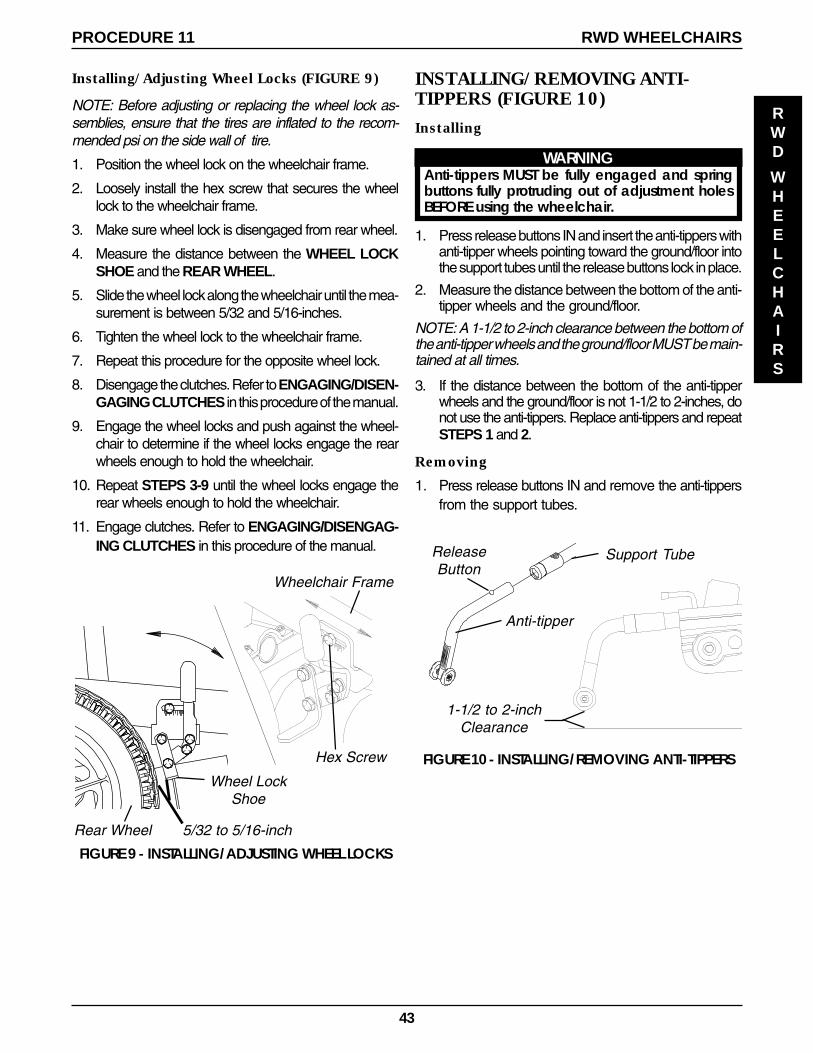
43
Installing/Adjusting Wheel Locks (FIGURE 9)
NOTE: Before adjusting or replacing the wheel lock as-semblies, ensure that the tires are inflated to the recom-mended psi on the side wall of tire.
1. Position the wheel lock on the wheelchair frame.
2. Loosely install the hex screw that secures the wheellock to the wheelchair frame.
3. Make sure wheel lock is disengaged from rear wheel.
4. Measure the distance between the WHEEL LOCKSHOE and the REAR WHEEL.
5. Slide the wheel lock along the wheelchair until the mea-surement is between 5/32 and 5/16-inches.
6. Tighten the wheel lock to the wheelchair frame.
7. Repeat this procedure for the opposite wheel lock.
8. Disengage the clutches. Refer to ENGAGING/DISEN-GAGING CLUTCHES in this procedure of the manual.
9. Engage the wheel locks and push against the wheel-chair to determine if the wheel locks engage the rearwheels enough to hold the wheelchair.
10. Repeat STEPS 3-9 until the wheel locks engage therear wheels enough to hold the wheelchair.
11. Engage clutches. Refer to ENGAGING/DISENGAG-ING CLUTCHES in this procedure of the manual.
5/32 to 5/16-inch
Wheel LockShoe
FIGURE 9 - INSTALLING/ADJUSTING WHEEL LOCKS
Rear Wheel
Hex Screw
Wheelchair Frame
PROCEDURE 11 RWD WHEELCHAIRS
RWD
WHEELCHAIRS
Support TubeReleaseButton
Anti-tipper
1-1/2 to 2-inchClearance
FIGURE 10 - INSTALLING/REMOVING ANTI-TIPPERS
INSTALLING/REMOVING ANTI-TIPPERS (FIGURE 10)
Installing
WARNINGAnti-tippers MUST be fully engaged and springbuttons fully protruding out of adjustment holesBEFORE using the wheelchair.
1. Press release buttons IN and insert the anti-tippers withanti-tipper wheels pointing toward the ground/floor intothe support tubes until the release buttons lock in place.
2. Measure the distance between the bottom of the anti-tipper wheels and the ground/floor.
NOTE: A 1-1/2 to 2-inch clearance between the bottom ofthe anti-tipper wheels and the ground/floor MUST be main-tained at all times.
3. If the distance between the bottom of the anti-tipperwheels and the ground/floor is not 1-1/2 to 2-inches, donot use the anti-tippers. Replace anti-tippers and repeatSTEPS 1 and 2.
Removing
1. Press release buttons IN and remove the anti-tippersfrom the support tubes.
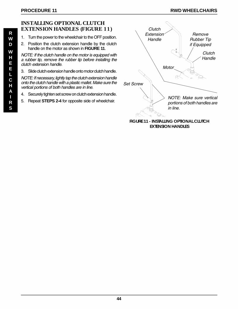
44
INSTALLING OPTIONAL CLUTCHEXTENSION HANDLES (FIGURE 11)1. Turn the power to the wheelchair to the OFF position.
2. Position the clutch extension handle by the clutchhandle on the motor as shown in FIGURE 11.
NOTE: If the clutch handle on the motor is equipped witha rubber tip, remove the rubber tip before installing theclutch extension handle.
3. Slide clutch extension handle onto motor clutch handle.
NOTE: If necessary, lightly tap the clutch extension handleonto the clutch handle with a plastic mallet. Make sure thevertical portions of both handles are in line.
4. Securely tighten set screw on clutch extension handle.
5. Repeat STEPS 2-4 for opposite side of wheelchair.
ClutchExtension
Handle
ClutchHandle
Motor
RemoveRubber Tipif Equipped
NOTE: Make sure verticalportions of both handles arein line.
Set Screw
FIGURE 11 - INSTALLING OPTIONAL CLUTCHEXTENSION HANDLES
PROCEDURE 11 RWD WHEELCHAIRS
RWD
WHEELCHAIRS

45
NOTES
NOTES
NOTES

46
NOTES
NOTES
NOTES

47
LIMITED WARRANTYPLEASE NOTE: THE WARRANTY BELOW HAS BEEN DRAFTED TO COMPLY WITH FEDERAL LAW APPLICABLETO PRODUCTS MANUFACTURED AFTER JULY 4, 1975.
This warranty is extended only to the original purchaser/user of our products.
This warranty gives you specific legal rights and you may also have other legal rights which vary fromstate to state.
Invacare warrants the side frames and crossbraces to be free from defects in materials and workman-ship for a period of five (5) years from date of purchase; electronics for a period of one (1) year from thedate of purchase; motors and gearboxes for a period of twelve (12) months from the date of pur-chase; all remaining components (including gas cylinders for recliners) for one (1) year from the dateof purchase except upholstered materials, padded materials and tires/wheels. If within such warrantyperiod any product shall be proven to be defective, such product shall be repaired or replaced, atInvacare's option. This warranty does not include any labor or shipping charges incurred in replace-ment part installation or repair of any such product. Invacare's sole obligation and your exclusiveremedy under this warranty shall be limited to such repair and/or replacement.
For warranty service, please contact the dealer from whom you purchased your Invacare product. Inthe event you do not receive satisfactory warranty service, please write directly to Invacare at theaddress on the back cover. Provide dealer's name address, date of purchase, indicate nature of thedefect and, if the product is serialized, indicate the serial number. Do not return products to our factorywithout our prior consent.
LIMITATIONS AND EXCLUSIONS: THE FOREGOING WARRANTY SHALL NOT APPLY TO SERIAL NUMBERED PROD-UCTS IF THE SERIAL NUMBER HAS BEEN REMOVED OR DEFACED, PRODUCTS SUBJECT TO NEGLIGENCE,ACCIDENT, IMPROPER OPERATION, MAINTENANCE OR STORAGE, COMMERCIAL OR INSTITUTIONAL USE,PRODUCTS MODIFIED WITHOUT INVACARE'S EXPRESS WRITTEN CONSENT INCLUDING, BUT NOT LIMITED TO,MODIFICATION THROUGH THE USE OF UNAUTHORIZED PARTS OR ATTACHMENTS; PRODUCTS DAMAGED BYREASON OF REPAIRS MADE TO ANY COMPONENT WITHOUT THE SPECIFIC CONSENT OF INVACARE, OR TOA PRODUCT DAMAGED BY CIRCUMSTANCES BEYOND INVACARE'S CONTROL, AND SUCH EVALUATIONWILL BE SOLELY DETERMINED BY INVACARE. THE WARRANTY SHALL NOT APPLY TO PROBLEMS ARISINGFROM NORMAL WEAR OR FAILURE TO ADHERE TO THESE INSTRUCTIONS. A CHANGE IN OPERATING NOISE,PARTICULARLY RELATIVE TO MOTORS AND GEARBOXES DOES NOT CONSTITUTE A FAILURE. ALL SUCH DE-VICES WILL EXHIBIT A CHANGE IN OPERATING NOISE DUE TO AGING.
THE FOREGOING WARRANTY IS EXCLUSIVE AND IN LIEU OF ALL OTHER EXPRESS WARRANTIES. IMPLIEDWARRANTIES, IF ANY, INCLUDING THE IMPLIED WARRANTIES OF MERCHANTABILITY AND FITNESS FOR APARTICULAR PURPOSE, SHALL NOT EXTEND BEYOND THE DURATION OF THE EXPRESSED WARRANTY PRO-VIDED HEREIN AND THE REMEDY FOR VIOLATIONS OF ANY IMPLIED WARRANTY SHALL BE LIMITED TOREPAIR OR REPLACEMENT OF THE DEFECTIVE PRODUCT PURSUANT TO THE TERMS CONTAINED HEREIN.INVACARE SHALL NOT BE LIABLE FOR ANY CONSEQUENTIAL OR INCIDENTAL DAMAGES WHATSOEVER.
THIS WARRANTY SHALL BE EXTENDED TO COMPLY WITH STATE/PROVINCIAL LAWS AND REQUIREMENTS.
WARRANTY
WARRANTY

���������������� �������������� !
�� �����������������" #$%&��'�(� �)'���" ����������(�*�+��" ,���������)��(�!��-+� .���������/"������'� ����� ��++�++�,0�����)��� � �1 ��)� ��22&345676# �#��3�$������(� 8
�
6&&&���������� �1 ��)� �9&&533354$&& $;$&59939 � �!� ��$956%&����������:��)� ��7&9&%3%���������������;7<�5�#=&&