implantable ultrasound devices
TRANSCRIPT
Implantable Ultrasound Devices
David Vilkomerson, Thomas Chilipka, John Bogan, DVX, llc, Princeton, NJ; John Blebea, Rashad Choudry, John Wang, Michael Salvatore, Vittorio Rotella, Krish Soundararajan, Temple
University, Philadelphia, PA
ABSTRACT Using medical implants to wirelessly report physiological data is a technique that is rapidly growing. Ultrasound is well-suited for implants -- it requires little power and this form of radiated energy has no ill effects on the body. We report here on techniques we have developed in our experience gained in implanting over a dozen Doppler ultrasound flow-measuring implants in dogs. The goal of our implantable device is to measure flow in an arterial graft. To accomplish this, we place a Doppler transducer in the wall of a graft and an implant unit under the skin that energizes the 20 MHz Doppler transducer system, either when started by external command or by internal timetable. The implant records the digitized Doppler real and imaginary channels and transmits the data to a nearby portable computer for storage and evaluation. After outlining the overall operation of the system, we will concentrate on three areas of implant design where special techniques are required: ensuring safety, including biocompatibility to prevent the body from reacting to its invasion; powering the device, including minimizing energy used so that a small battery can provide long-life; and transmitting the data obtained. Keywords: implant, telemetry, blood flow measurement, graft monitoring, biocompatibility, Doppler, MICS
1. INTRODUCTION
Since the first pacemaker was implanted almost 50 years ago1, hundreds of thousands of life-saving and life-enhancing electronic devices have been implanted. One individual might have as many as eight active electronic implants in his body: in his head, a cochlear implant to hear and a neural stimulator to control the effects of Parkinson’s disease; in his body, a pacemaker to make his heart beat, an insulin pump for his diabetes, a drug pump for his cancer, a spinal cord stimulator for back pain, and a bladder stimulator for incontinence; and in his legs, a bone-growth stimulator to speed repair of a broken leg. He may also need a new device that controls hypertension, a carotid sinus stimulator2, and, sick as he is, eventually an artificial heart. Ultrasound devices are well suited for implantation. They can be small and use little power, and ultrasound emissions are considered safe when held below FDA-stipulated limits3. Very small and very low-powered electronic components developed for cell phones, PDA’s, portable computers and music players can be exploited for implantable ultrasound devices. A purpose of this paper is to bring to the ultrasound device community techniques that will be useful when developing ultrasound implantables. We will use as an illustrative example an implantable ultrasound device we have developed to measure blood flow in artificial arteries that has been implanted in over a dozen dogs. We will first briefly describe the device, and then address three major areas of ultrasound device design that are required for an implantable devices: 1) making a safe device; 2) powering the device, and 3) gathering and transmitting data in and out of the device.
2. THE “SMART GRAFT” Seventy thousand times a year a prosthetic graft is implanted in legs whose arteries have ceased to bring enough blood to the tissues of the leg. While these grafts can improve a person’s quality of life or save a leg from amputation, they can fail without warning – most fail in less than five years, with many leading to an amputation of that limb4.
Medical Imaging 2008: Ultrasonic Imaging and Signal Processing, edited by Stephen A. McAleavey,Jan D'hooge, Proc. of SPIE Vol. 6920, 69200C, (2008) · 1605-7422/08/$18 · doi: 10.1117/12.772845
Proc. of SPIE Vol. 6920 69200C-12008 SPIE Digital Library -- Subscriber Archive Copy
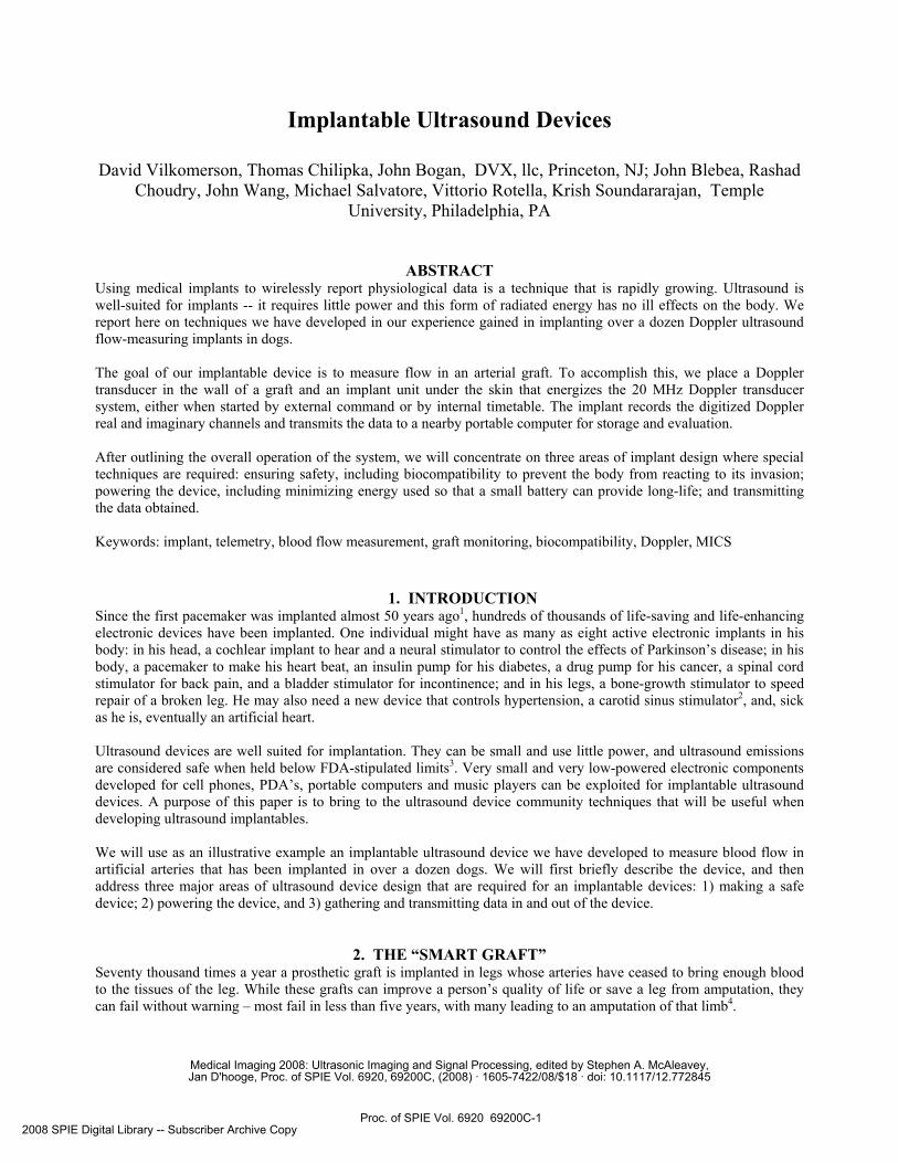
It has been shown that impending failure of a graft can be detected by reduced flow in the graft. However, flow declines over a period of time shorter than the semi-yearly or quarterly interval between ultrasound measurements of flow.5 By using a special ultrasound transducer we have developed, the diffraction-grating transducer6, we can build a Doppler flow-sensor within the wall of an artificial graft. The implanted electronics unit interrogate the flow sensor nightly to measure the blood flow in the graft and send that data to a bedside monitor. A computer within the bedside monitor could calculate the flow in the graft and, if declining flow indicated
impending graft failure, send an email to the patient’s doctor triggering an intervention to prevent the graft from failing. The details of this “smart graft” are provided in Ref [7], and a schematic representation of the system is shown in Fig.1.
3. MAKING A SAFE DEVICE “To help, or at least do no harm.8”This Hippocratic aphorism from the 5th century BCE is still central to medical practice. As such, any implantable device must be designed for safe implantation. 3.1 Sterility Everything going into the body must be sterile, otherwise infection, often with disastrous results, will follow. Heat kills bacteria, viruses, etc, so the most common method of sterilization for scalpels and other operating tools is autoclaving: placing the object to be sterilized in a vessel containing high pressure steam, at either 121°C for 15 minutes or 134°C for 3 minutes. However, unless especially selected, ultrasound transducers, electronic components and associated plastic parts will not survive autoclaving temperatures and pressures. When in doubt, do not autoclave an ultrasound device. There are other means of sterilization that do not require these high temperatures and pressures. Gamma ray irradiation and hydrogen-peroxide methods are often used in manufacturing. For research devices, the most often used sterilization procedure is the ethylene oxide method, known as EtO, which requires temperatures of about 50° C, does not affect plastics and rubbers, and is available at most research settings. The main drawback of EtO is that it requires a relatively long time to achieve sterility – three or four hours of exposure to the gas plus as much as 24 hours for post-exposure aeration. This allows any plastic or other absorptive materials to release the EtO and become safe for implantation. If you want to implant Wednesday morning, you must get the device in to be EtO’d by Monday afternoon. When you get involved in the implantation of devices, you will soon learn the importance of sterility in the operating room during implantation. The best advice is to always follow the instructions of the surgeon – and, when in doubt, do not touch anything or enter the “sterile field” that surrounds the operating table. 3.2 Biocompatibility For the device to be safe for implantation, any materials in contact with body tissue must be biocompatible, i.e. will not cause significant irritation, inflammation, cell death, cancer, affect reproduction or interact with blood. There are established standards for testing a medical device for biocompatibility: the ISO 109939 set of standards, in 20 parts covering what tests to do and how to do it. The FDA has effectively adopted (“harmonized”) its tests to these tests, which must be performed before any implantable medical device becomes cleared for sale. It should be noted that to gain clearance the device itself must be tested – saying the device is made of biocompatible materials is not enough to gain clearance. When developing a device, any materials that come in contact with tissue should pass the 10993 tests. (A good introduction to these considerations is Ref. 10) Such materials include, for example, certain kinds of stainless steel (316-L or 316-LVM, but not conventional varieties), certain alloys of titanium (Ti-6A-4V), and rubbers and plastics that are classified as USP Class 611.
BedsideMonitor
MICS403-405 MHz
Internet
Fig. 1. The SmartGraft™ system
Proc. of SPIE Vol. 6920 69200C-2
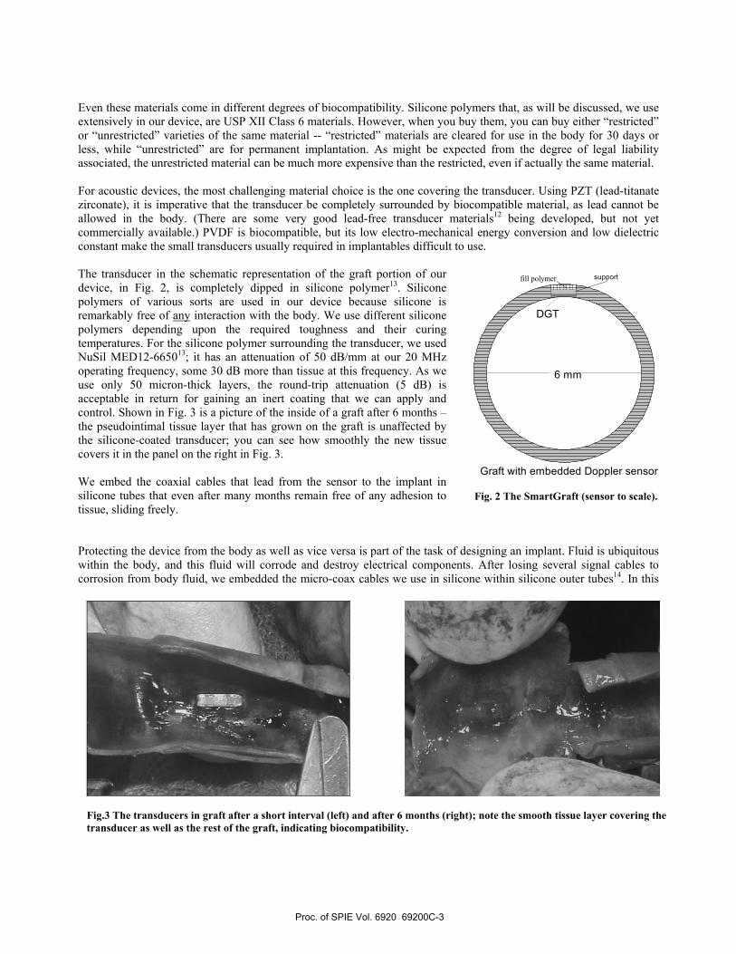
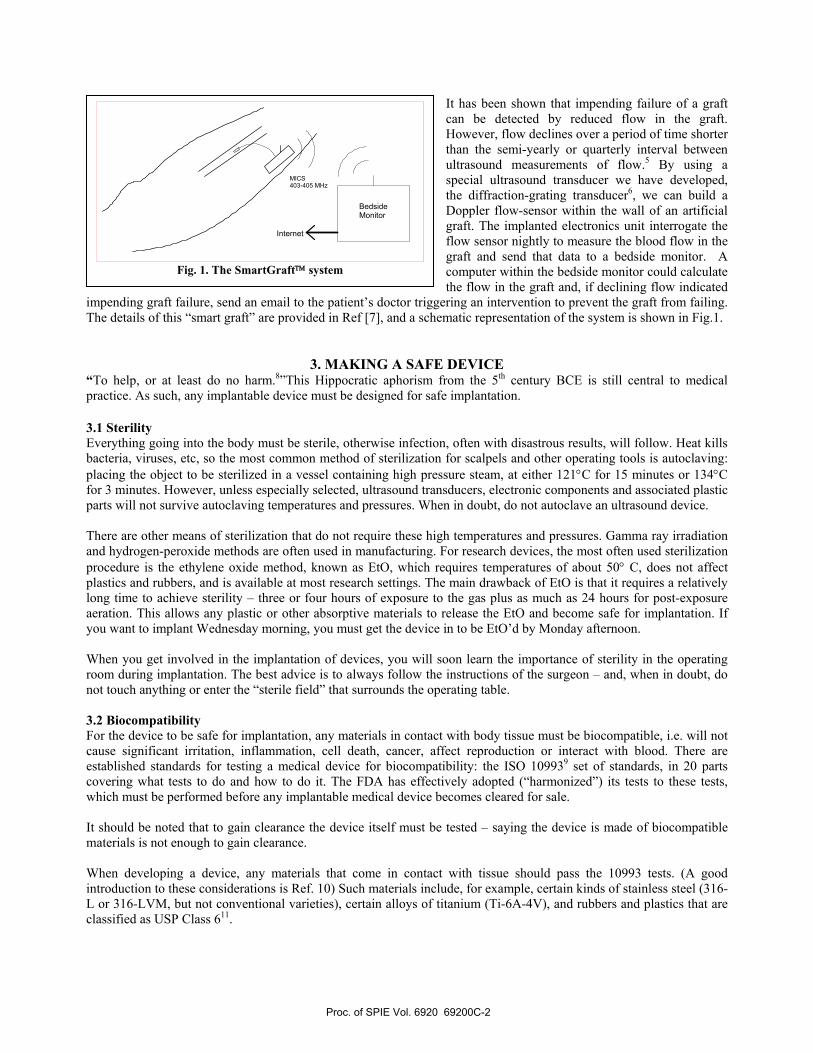
Even these materials come in different degrees of biocompatibility. Silicone polymers that, as will be discussed, we use extensively in our device, are USP XII Class 6 materials. However, when you buy them, you can buy either “restricted” or “unrestricted” varieties of the same material -- “restricted” materials are cleared for use in the body for 30 days or less, while “unrestricted” are for permanent implantation. As might be expected from the degree of legal liability associated, the unrestricted material can be much more expensive than the restricted, even if actually the same material. For acoustic devices, the most challenging material choice is the one covering the transducer. Using PZT (lead-titanate zirconate), it is imperative that the transducer be completely surrounded by biocompatible material, as lead cannot be allowed in the body. (There are some very good lead-free transducer materials12 being developed, but not yet commercially available.) PVDF is biocompatible, but its low electro-mechanical energy conversion and low dielectric constant make the small transducers usually required in implantables difficult to use. The transducer in the schematic representation of the graft portion of our device, in Fig. 2, is completely dipped in silicone polymer13. Silicone polymers of various sorts are used in our device because silicone is remarkably free of any interaction with the body. We use different silicone polymers depending upon the required toughness and their curing temperatures. For the silicone polymer surrounding the transducer, we used NuSil MED12-665013; it has an attenuation of 50 dB/mm at our 20 MHz operating frequency, some 30 dB more than tissue at this frequency. As we use only 50 micron-thick layers, the round-trip attenuation (5 dB) is acceptable in return for gaining an inert coating that we can apply and control. Shown in Fig. 3 is a picture of the inside of a graft after 6 months – the pseudointimal tissue layer that has grown on the graft is unaffected by the silicone-coated transducer; you can see how smoothly the new tissue covers it in the panel on the right in Fig. 3. We embed the coaxial cables that lead from the sensor to the implant in silicone tubes that even after many months remain free of any adhesion to tissue, sliding freely. Protecting the device from the body as well as vice versa is part of the task of designing an implant. Fluid is ubiquitous within the body, and this fluid will corrode and destroy electrical components. After losing several signal cables to corrosion from body fluid, we embedded the micro-coax cables we use in silicone within silicone outer tubes14. In this
6 mm
DGT
Graft with embedded Doppler sensor
fill polymer support
Fig. 2 The SmartGraft (sensor to scale).
Fig.3 The transducers in graft after a short interval (left) and after 6 months (right); note the smooth tissue layer covering the transducer as well as the rest of the graft, indicating biocompatibility.
Proc. of SPIE Vol. 6920 69200C-3
•
••
way, kinking, nicking, or a not fully sealed connector will not cause a failure of the system. We should add there is another material frequently used to make devices implantable -- Parylene15, (poly-para-xylylene). This material in a gaseous form fills a chamber in which the device is placed. Parylene then polymerizes onto the object, covering wherever the gas could penetrate (i.e. every nook and cranny) with a thin coating that is crystal clear and of high dielectric strength. How thick the layer is can be controlled by time and pressure; layers as thin as a micron can be reliably made. It has good acoustic characteristics – a longitudinal velocity only about 1.4 that of water, and an impedance relative to water of ~1.716. It has low acoustic attenuation. It is often used as a matching layer. We have used it in the past to coat intra-vessel receiver transducers as guidance beacons17. While this material has many good attributes, it may be difficult to use in a research environment unless you have your own means of making these layers. It may take a week or more to have Parylene applied to a sample of your device, and it make take several tries to get the desired layer thickness. We also did not like the “waxy” surface obtained, fearing some mechanical abrasion would flake pieces of it off -- something not of concern with the tough elastic films of silicone we use. However, it is a good biocompatible material that should be considered for implantables, particularly when very thin layers and mechanically isolated components are considered.
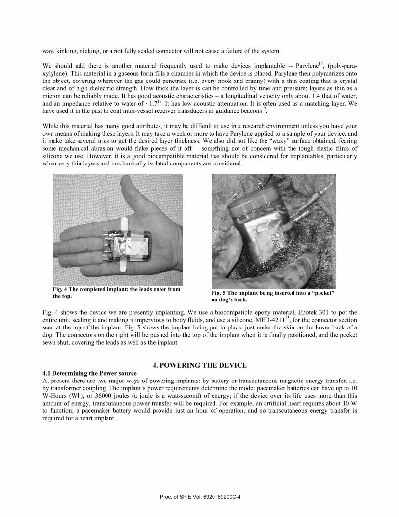
Fig. 4 shows the device we are presently implanting. We use a biocompatible epoxy material, Epotek 301 to pot the entire unit, sealing it and making it impervious to body fluids, and use a silicone, MED-421113, for the connector section seen at the top of the implant. Fig. 5 shows the implant being put in place, just under the skin on the lower back of a dog. The connectors on the right will be pushed into the top of the implant when it is finally positioned, and the pocket sewn shut, covering the leads as well as the implant.
4. POWERING THE DEVICE 4.1 Determining the Power source At present there are two major ways of powering implants: by battery or transcutaneous magnetic energy transfer, i.e. by transformer coupling. The implant’s power requirements determine the mode: pacemaker batteries can have up to 10 W-Hours (Wh), or 36000 joules (a joule is a watt-second) of energy; if the device over its life uses more than this amount of energy, transcutaneous power transfer will be required. For example, an artificial heart requires about 10 W to function; a pacemaker battery would provide just an hour of operation, and so transcutaneous energy transfer is required for a heart implant.
Fig. 4 The completed implant; the leads enter from the top.
Fig. 5 The implant being inserted into a “pocket” on dog’s back.
Proc. of SPIE Vol. 6920 69200C-4
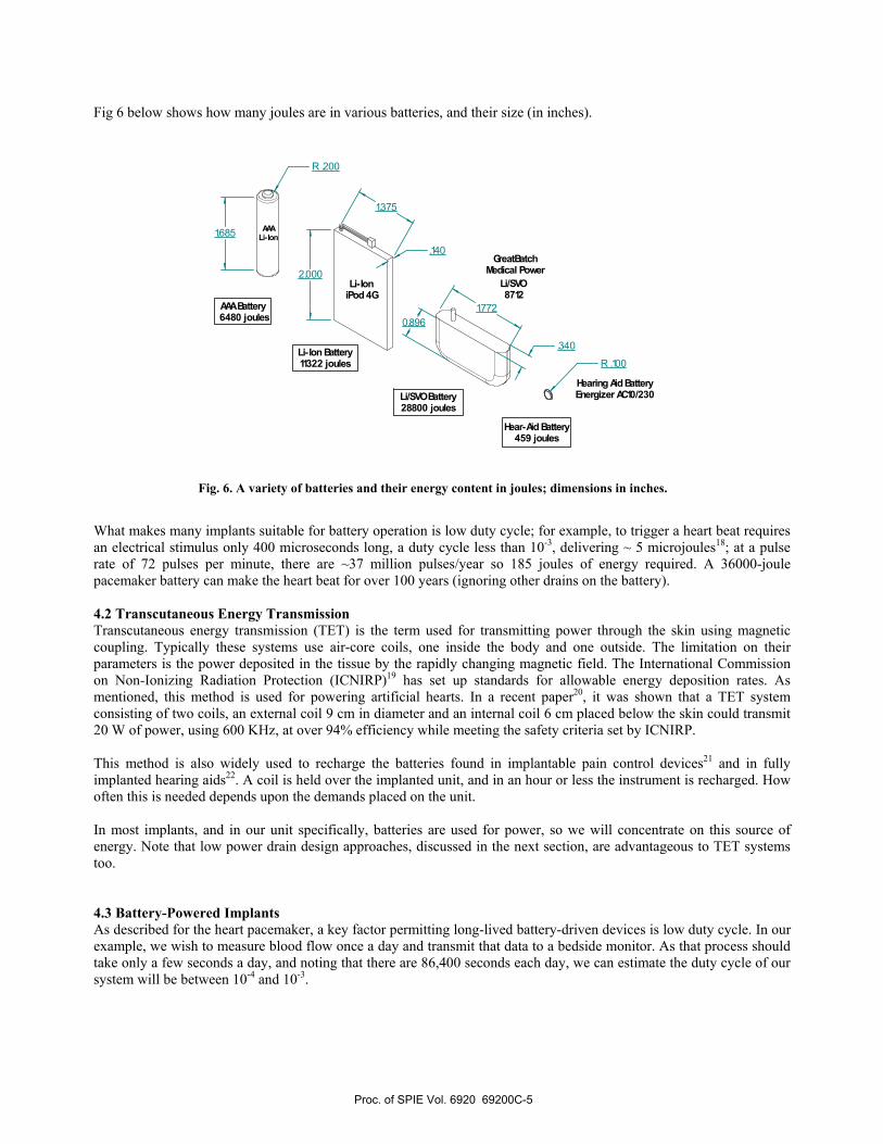
Fig 6 below shows how many joules are in various batteries, and their size (in inches).
What makes many implants suitable for battery operation is low duty cycle; for example, to trigger a heart beat requires an electrical stimulus only 400 microseconds long, a duty cycle less than 10-3, delivering ~ 5 microjoules18; at a pulse rate of 72 pulses per minute, there are ~37 million pulses/year so 185 joules of energy required. A 36000-joule pacemaker battery can make the heart beat for over 100 years (ignoring other drains on the battery). 4.2 Transcutaneous Energy Transmission Transcutaneous energy transmission (TET) is the term used for transmitting power through the skin using magnetic coupling. Typically these systems use air-core coils, one inside the body and one outside. The limitation on their parameters is the power deposited in the tissue by the rapidly changing magnetic field. The International Commission on Non-Ionizing Radiation Protection (ICNIRP)19 has set up standards for allowable energy deposition rates. As mentioned, this method is used for powering artificial hearts. In a recent paper20, it was shown that a TET system consisting of two coils, an external coil 9 cm in diameter and an internal coil 6 cm placed below the skin could transmit 20 W of power, using 600 KHz, at over 94% efficiency while meeting the safety criteria set by ICNIRP. This method is also widely used to recharge the batteries found in implantable pain control devices21 and in fully implanted hearing aids22. A coil is held over the implanted unit, and in an hour or less the instrument is recharged. How often this is needed depends upon the demands placed on the unit. In most implants, and in our unit specifically, batteries are used for power, so we will concentrate on this source of energy. Note that low power drain design approaches, discussed in the next section, are advantageous to TET systems too. 4.3 Battery-Powered Implants As described for the heart pacemaker, a key factor permitting long-lived battery-driven devices is low duty cycle. In our example, we wish to measure blood flow once a day and transmit that data to a bedside monitor. As that process should take only a few seconds a day, and noting that there are 86,400 seconds each day, we can estimate the duty cycle of our system will be between 10-4 and 10-3.
2.000
1.7720.896
.140
R .200
.340
R .100
AAALi-Ion
Li-IoniPod 4G
Li/SVO 8712
Hearing Aid BatteryEnergizer AC10/230
AAA Battery 6480 joules
Li-Ion Battery11322 joules
Li/SVO Battery28800 joules
Hear-Aid Battery459 joules
1.375
GreatBatchMedical Power
1.685
Fig. 6. A variety of batteries and their energy content in joules; dimensions in inches.
Proc. of SPIE Vol. 6920 69200C-5
EXT
F ROMRECSENSOR
TOXM ITIN
GRAFT
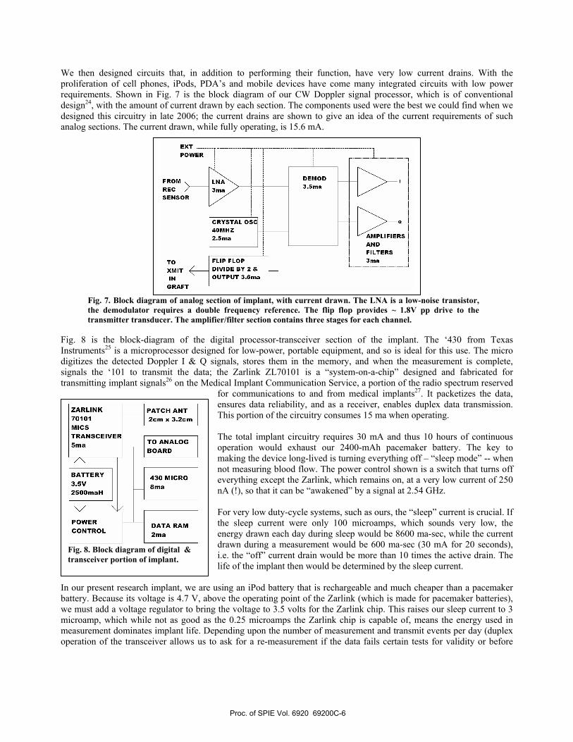
We then designed circuits that, in addition to performing their function, have very low current drains. With the proliferation of cell phones, iPods, PDA’s and mobile devices have come many integrated circuits with low power requirements. Shown in Fig. 7 is the block diagram of our CW Doppler signal processor, which is of conventional design24, with the amount of current drawn by each section. The components used were the best we could find when we designed this circuitry in late 2006; the current drains are shown to give an idea of the current requirements of such analog sections. The current drawn, while fully operating, is 15.6 mA.
Fig. 7. Block diagram of analog section of implant, with current drawn. The LNA is a low-noise transistor, the demodulator requires a double frequency reference. The flip flop provides ~ 1.8V pp drive to the transmitter transducer. The amplifier/filter section contains three stages for each channel.
Fig. 8 is the block-diagram of the digital processor-transceiver section of the implant. The ‘430 from Texas Instruments25 is a microprocessor designed for low-power, portable equipment, and so is ideal for this use. The micro digitizes the detected Doppler I & Q signals, stores them in the memory, and when the measurement is complete, signals the ‘101 to transmit the data; the Zarlink ZL70101 is a “system-on-a-chip” designed and fabricated for transmitting implant signals26 on the Medical Implant Communication Service, a portion of the radio spectrum reserved
for communications to and from medical implants27. It packetizes the data, ensures data reliability, and as a receiver, enables duplex data transmission. This portion of the circuitry consumes 15 ma when operating. The total implant circuitry requires 30 mA and thus 10 hours of continuous operation would exhaust our 2400-mAh pacemaker battery. The key to making the device long-lived is turning everything off – “sleep mode” -- when not measuring blood flow. The power control shown is a switch that turns off everything except the Zarlink, which remains on, at a very low current of 250 nA (!), so that it can be “awakened” by a signal at 2.54 GHz. For very low duty-cycle systems, such as ours, the “sleep” current is crucial. If the sleep current were only 100 microamps, which sounds very low, the energy drawn each day during sleep would be 8600 ma-sec, while the current drawn during a measurement would be 600 ma-sec (30 mA for 20 seconds), i.e. the “off” current drain would be more than 10 times the active drain. The life of the implant then would be determined by the sleep current.
In our present research implant, we are using an iPod battery that is rechargeable and much cheaper than a pacemaker battery. Because its voltage is 4.7 V, above the operating point of the Zarlink (which is made for pacemaker batteries), we must add a voltage regulator to bring the voltage to 3.5 volts for the Zarlink chip. This raises our sleep current to 3 microamp, which while not as good as the 0.25 microamps the Zarlink chip is capable of, means the energy used in measurement dominates implant life. Depending upon the number of measurement and transmit events per day (duplex operation of the transceiver allows us to ask for a re-measurement if the data fails certain tests for validity or before
Fig. 8. Block diagram of digital & transceiver portion of implant.
Proc. of SPIE Vol. 6920 69200C-6
•ii
21
3k
411
CE
NT
IME
TE
RS
F
R
I I:
(
3 4
5 6
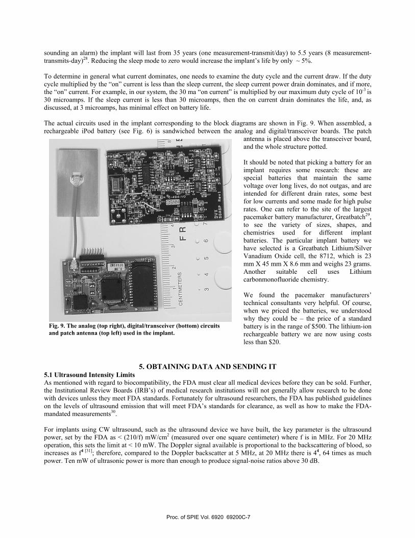
sounding an alarm) the implant will last from 35 years (one measurement-transmit/day) to 5.5 years (8 measurement-transmits-day)28. Reducing the sleep mode to zero would increase the implant’s life by only ~ 5%. To determine in general what current dominates, one needs to examine the duty cycle and the current draw. If the duty cycle multiplied by the “on” current is less than the sleep current, the sleep current power drain dominates, and if more, the “on” current. For example, in our system, the 30 ma “on current” is multiplied by our maximum duty cycle of 10-3 is 30 microamps. If the sleep current is less than 30 microamps, then the on current drain dominates the life, and, as discussed, at 3 microamps, has minimal effect on battery life. The actual circuits used in the implant corresponding to the block diagrams are shown in Fig. 9. When assembled, a rechargeable iPod battery (see Fig. 6) is sandwiched between the analog and digital/transceiver boards. The patch
antenna is placed above the transceiver board, and the whole structure potted. It should be noted that picking a battery for an implant requires some research: these are special batteries that maintain the same voltage over long lives, do not outgas, and are intended for different drain rates, some best for low currents and some made for high pulse rates. One can refer to the site of the largest pacemaker battery manufacturer, Greatbatch29, to see the variety of sizes, shapes, and chemistries used for different implant batteries. The particular implant battery we have selected is a Greatbatch Lithium/Silver Vanadium Oxide cell, the 8712, which is 23 mm X 45 mm X 8.6 mm and weighs 23 grams. Another suitable cell uses Lithium carbonmonofluoride chemistry. We found the pacemaker manufacturers’ technical consultants very helpful. Of course, when we priced the batteries, we understood why they could be – the price of a standard battery is in the range of $500. The lithium-ion rechargeable battery we are now using costs less than $20.
5. OBTAINING DATA AND SENDING IT 5.1 Ultrasound Intensity Limits As mentioned with regard to biocompatibility, the FDA must clear all medical devices before they can be sold. Further, the Institutional Review Boards (IRB’s) of medical research institutions will not generally allow research to be done with devices unless they meet FDA standards. Fortunately for ultrasound researchers, the FDA has published guidelines on the levels of ultrasound emission that will meet FDA’s standards for clearance, as well as how to make the FDA-mandated measurements30. For implants using CW ultrasound, such as the ultrasound device we have built, the key parameter is the ultrasound power, set by the FDA as < (210/f) mW/cm2 (measured over one square centimeter) where f is in MHz. For 20 MHz operation, this sets the limit at < 10 mW. The Doppler signal available is proportional to the backscattering of blood, so increases as f4 [31]; therefore, compared to the Doppler backscatter at 5 MHz, at 20 MHz there is 44, 64 times as much power. Ten mW of ultrasonic power is more than enough to produce signal-noise ratios above 30 dB.
Fig. 9. The analog (top right), digital/transceiver (bottom) circuits and patch antenna (top left) used in the implant.
Proc. of SPIE Vol. 6920 69200C-7
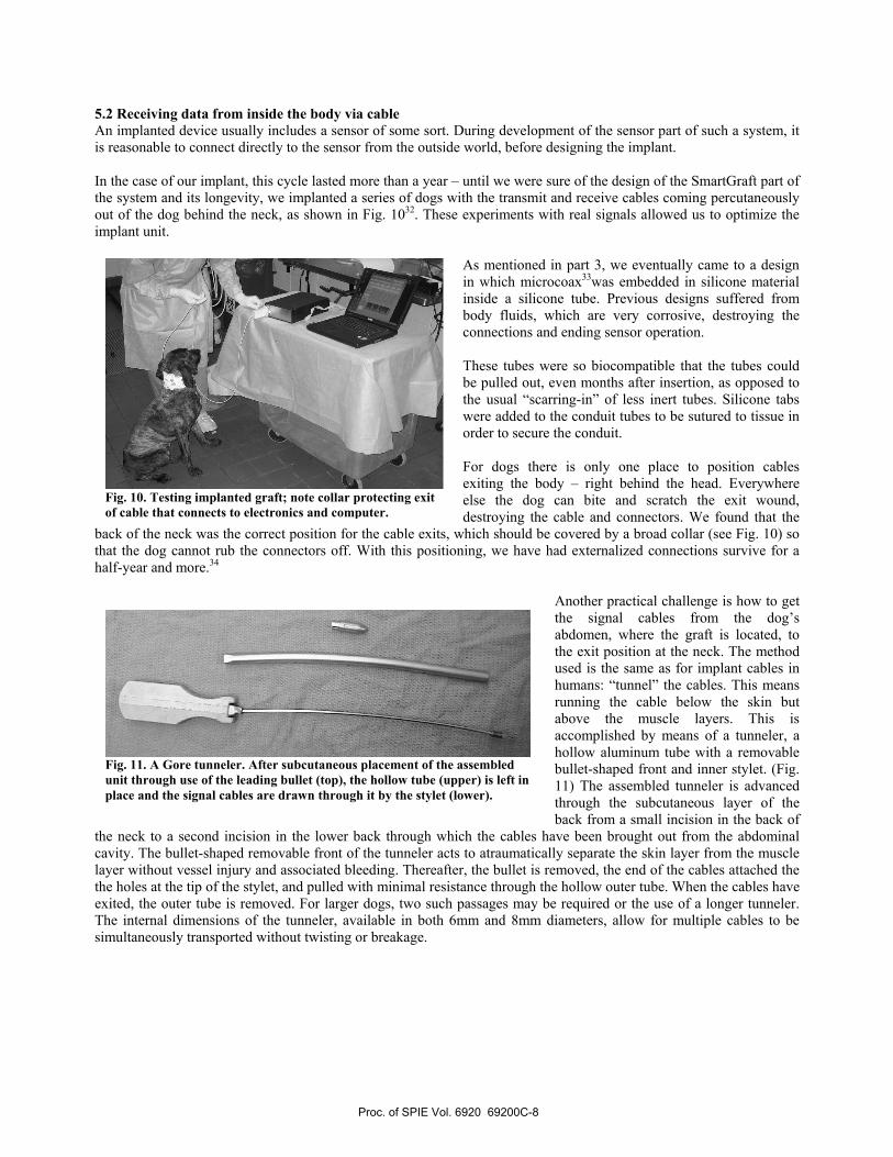
5.2 Receiving data from inside the body via cable An implanted device usually includes a sensor of some sort. During development of the sensor part of such a system, it is reasonable to connect directly to the sensor from the outside world, before designing the implant. In the case of our implant, this cycle lasted more than a year – until we were sure of the design of the SmartGraft part of the system and its longevity, we implanted a series of dogs with the transmit and receive cables coming percutaneously out of the dog behind the neck, as shown in Fig. 1032. These experiments with real signals allowed us to optimize the implant unit.
As mentioned in part 3, we eventually came to a design in which microcoax33was embedded in silicone material inside a silicone tube. Previous designs suffered from body fluids, which are very corrosive, destroying the connections and ending sensor operation. These tubes were so biocompatible that the tubes could be pulled out, even months after insertion, as opposed to the usual “scarring-in” of less inert tubes. Silicone tabs were added to the conduit tubes to be sutured to tissue in order to secure the conduit. For dogs there is only one place to position cables exiting the body – right behind the head. Everywhere else the dog can bite and scratch the exit wound, destroying the cable and connectors. We found that the
back of the neck was the correct position for the cable exits, which should be covered by a broad collar (see Fig. 10) so that the dog cannot rub the connectors off. With this positioning, we have had externalized connections survive for a half-year and more.34
Another practical challenge is how to get the signal cables from the dog’s abdomen, where the graft is located, to the exit position at the neck. The method used is the same as for implant cables in humans: “tunnel” the cables. This means running the cable below the skin but above the muscle layers. This is accomplished by means of a tunneler, a hollow aluminum tube with a removable bullet-shaped front and inner stylet. (Fig. 11) The assembled tunneler is advanced through the subcutaneous layer of the back from a small incision in the back of
the neck to a second incision in the lower back through which the cables have been brought out from the abdominal cavity. The bullet-shaped removable front of the tunneler acts to atraumatically separate the skin layer from the muscle layer without vessel injury and associated bleeding. Thereafter, the bullet is removed, the end of the cables attached the the holes at the tip of the stylet, and pulled with minimal resistance through the hollow outer tube. When the cables have exited, the outer tube is removed. For larger dogs, two such passages may be required or the use of a longer tunneler. The internal dimensions of the tunneler, available in both 6mm and 8mm diameters, allow for multiple cables to be simultaneously transported without twisting or breakage.
Fig. 10. Testing implanted graft; note collar protecting exit of cable that connects to electronics and computer.
Fig. 11. A Gore tunneler. After subcutaneous placement of the assembled unit through use of the leading bullet (top), the hollow tube (upper) is left in place and the signal cables are drawn through it by the stylet (lower).
Proc. of SPIE Vol. 6920 69200C-8
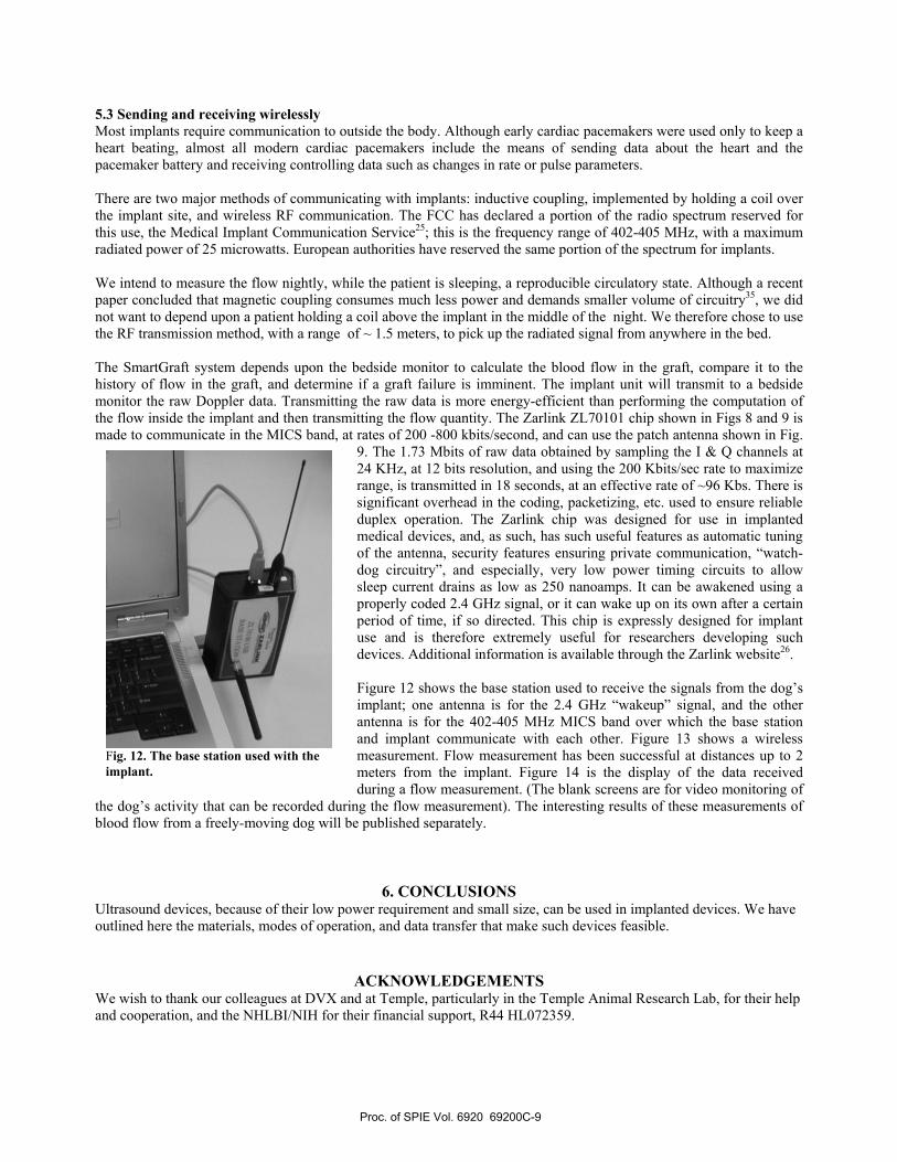
5.3 Sending and receiving wirelessly Most implants require communication to outside the body. Although early cardiac pacemakers were used only to keep a heart beating, almost all modern cardiac pacemakers include the means of sending data about the heart and the pacemaker battery and receiving controlling data such as changes in rate or pulse parameters. There are two major methods of communicating with implants: inductive coupling, implemented by holding a coil over the implant site, and wireless RF communication. The FCC has declared a portion of the radio spectrum reserved for this use, the Medical Implant Communication Service25; this is the frequency range of 402-405 MHz, with a maximum radiated power of 25 microwatts. European authorities have reserved the same portion of the spectrum for implants. We intend to measure the flow nightly, while the patient is sleeping, a reproducible circulatory state. Although a recent paper concluded that magnetic coupling consumes much less power and demands smaller volume of circuitry35, we did not want to depend upon a patient holding a coil above the implant in the middle of the night. We therefore chose to use the RF transmission method, with a range of ~ 1.5 meters, to pick up the radiated signal from anywhere in the bed. The SmartGraft system depends upon the bedside monitor to calculate the blood flow in the graft, compare it to the history of flow in the graft, and determine if a graft failure is imminent. The implant unit will transmit to a bedside monitor the raw Doppler data. Transmitting the raw data is more energy-efficient than performing the computation of the flow inside the implant and then transmitting the flow quantity. The Zarlink ZL70101 chip shown in Figs 8 and 9 is made to communicate in the MICS band, at rates of 200 -800 kbits/second, and can use the patch antenna shown in Fig.
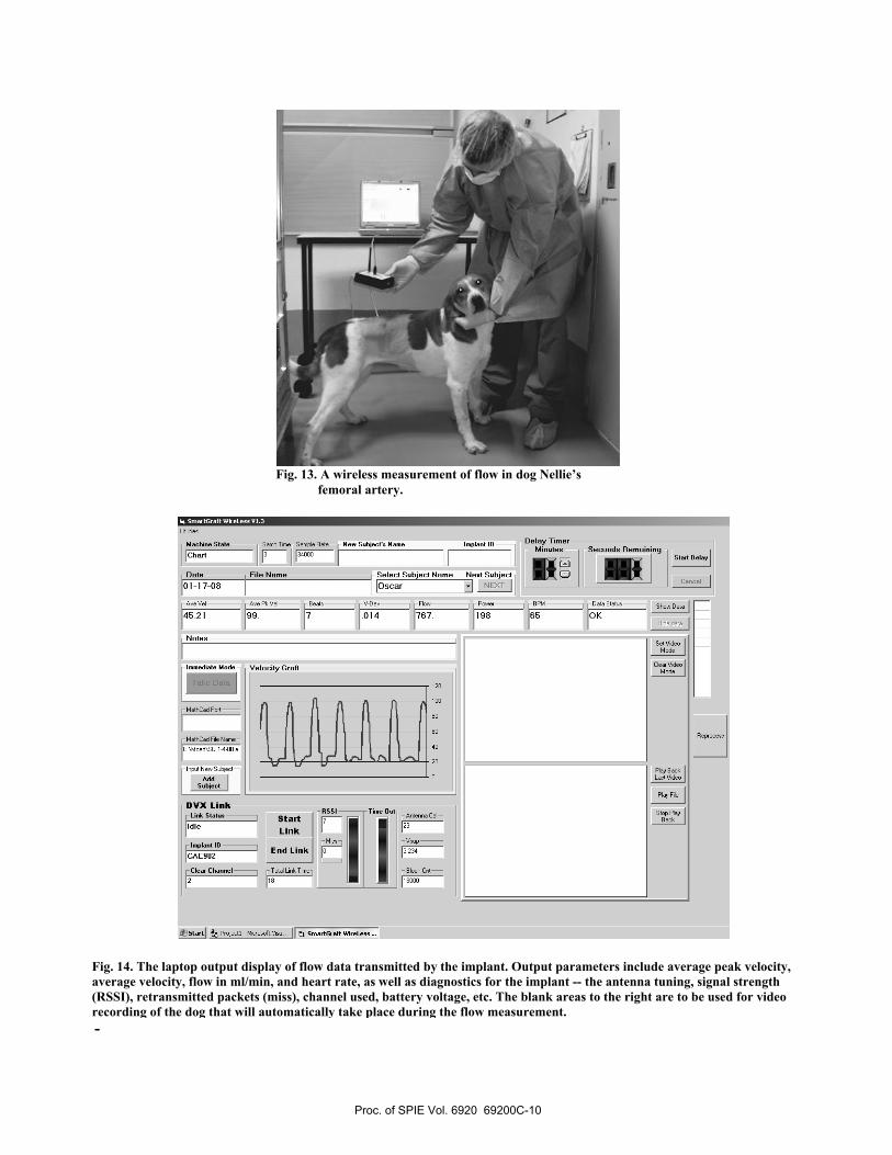
9. The 1.73 Mbits of raw data obtained by sampling the I & Q channels at 24 KHz, at 12 bits resolution, and using the 200 Kbits/sec rate to maximize range, is transmitted in 18 seconds, at an effective rate of ~96 Kbs. There is significant overhead in the coding, packetizing, etc. used to ensure reliable duplex operation. The Zarlink chip was designed for use in implanted medical devices, and, as such, has such useful features as automatic tuning of the antenna, security features ensuring private communication, “watch-dog circuitry”, and especially, very low power timing circuits to allow sleep current drains as low as 250 nanoamps. It can be awakened using a properly coded 2.4 GHz signal, or it can wake up on its own after a certain period of time, if so directed. This chip is expressly designed for implant use and is therefore extremely useful for researchers developing such devices. Additional information is available through the Zarlink website26. Figure 12 shows the base station used to receive the signals from the dog’s implant; one antenna is for the 2.4 GHz “wakeup” signal, and the other antenna is for the 402-405 MHz MICS band over which the base station and implant communicate with each other. Figure 13 shows a wireless measurement. Flow measurement has been successful at distances up to 2 meters from the implant. Figure 14 is the display of the data received during a flow measurement. (The blank screens are for video monitoring of
the dog’s activity that can be recorded during the flow measurement). The interesting results of these measurements of blood flow from a freely-moving dog will be published separately.
6. CONCLUSIONS Ultrasound devices, because of their low power requirement and small size, can be used in implanted devices. We have outlined here the materials, modes of operation, and data transfer that make such devices feasible.
ACKNOWLEDGEMENTS We wish to thank our colleagues at DVX and at Temple, particularly in the Temple Animal Research Lab, for their help and cooperation, and the NHLBI/NIH for their financial support, R44 HL072359.
Fig. 12. The base station used with the implant.
Proc. of SPIE Vol. 6920 69200C-9
— Machine SlaIn
Chad— Salop Teoe—Satople Pale N em Srahjerle Name Implanl ie Delay Timer
Minules Secends Remaining
Ness Subjecl—
NEXT
7JDale101-17-08
File Name i-Selecl Subiecl NameOsCar
Aye Vel rAoe Pk Vel-1 Best V-Dc', Fl',', Poooeo 8PM r Data Slaloo-1 S h',',Ds4521 99- 7 -014 1ST 198 65 OK
Hidedala
Del VideoMode
Cleat VideoMode
uuuuW
Neles
Immediale Mede Velecila Graft
:30:1-2
MathCad Poll]
MathCad Pile Natoe—1
[C:\MOad\SS 1-4-08 a
AddSuhjerl
DVX Link—
Idle
slam
essl__j_Tine
eel
Aooleooooa Cal—
lmrB;nlie End Link 1 1[deal
Channel Titte1 • •Jsraer P101e611 -etotosoltys,',, smaerseaftWieeLenn —.
Slall eelae
Cancel
'1 l ft 11 1
120
100
So
60
40
20L/ LiPlay BaokLaol Video
Play Pile
Slop PlayBaok
-
Fig. 14. The laptop output display of flow data transmitted by the implant. Output parameters include average peak velocity, average velocity, flow in ml/min, and heart rate, as well as diagnostics for the implant -- the antenna tuning, signal strength (RSSI), retransmitted packets (miss), channel used, battery voltage, etc. The blank areas to the right are to be used for video recording of the dog that will automatically take place during the flow measurement.
Fig. 13. A wireless measurement of flow in dog Nellie’s femoral artery.
Proc. of SPIE Vol. 6920 69200C-10

REFERENCES 1By Dr. Ake Senning, in Stockholm, October, 1958. The implant used 2 NiCad batteries that were recharged every two weeks by RF. See http://www.thebakken.org/artifacts/Elmqvist.htm 2 K. Illig et al, “ An implantable carotid sinus stimulator for drug-resistant hypertension: Surgical technique and short-term outcome from the multicenter phase II Rheos feasibility trial.” J Vasc Surg 2006;44:1213-8. 3 FDA/CDRH, “Information for Manufacturer’s Seeking Marketing Clearance of Diagnostic Ultrasound Systems and Transducers”, 9/30/97 4 C.L. Wixon et al, “An economic appraisal of lower extremity bypass graft maintenance”, J. Vasc Surgery 32:1-12, 2000 5 A. Lumsden et al, “Cost Efficacy of Duplex Surveillance and Prophylactic Angioplasty of Arteriovenous ePTFE grafts”, Annals Vasc Surgery 12: 138-142, 1998 6 D. Vilkomerson et al, “Diffraction-Grating Transducers”, Proc. Of 1997 IEEE Ultrasonics Symposium, 1691-1696, IEEE Press, Piscataway, 1998 7 D. Vilkomerson and T. Chilipka, “Implantable Doppler System for Self-Monitoring Vascular Grafts”, Proc. IEEE 2004 Ultrasonics Symposium, IEEE Press, Piscataway 2004 8 Hippocrates, Epidemics, Bk. I, Sect. V 9 International Standards Organization, ISO 10993 in 20 parts; see http://www.iso.org. 10 Kummula R and Morris J, “Considerations for the Biocompatibility Evaluation of Medical Devices”, MDDI May, 2001, available at www.devicelink.com/mddi/archive/01/05/008.html Read also the attached “”Regulation of Medical Devices: A primer”. 11 Noted on Manufacturer’s data sheets – see, for example, www.zeusinc.com/pdf/Zeus_Biocompatibility.pdf 12Safari A, Hagh, NM, “Lead-Free Peizoelectric Transducer in the K1/2N1/2NbO3-LiTaO3-LiSbO3 Solid Solution System”, Proc. 2006 IEEE Ultrasonics Symposium, IEEE Press, Piscataway 2007. 13 NuSil Silicone Technology www.nusil.com 14 The micro-coax is .81 mm diameter, and two are placed in a silicone tube .192” OD, .044” ID silicone tubing from A-M Systems, and filled with NuSil MED-421. 15 See www.vp-scientific.com/parylene_properties.htm for good outline of parylene properties and application. 16 Onda, www.ondacorp.com/tables/Plastics.pdf 17 Vilkomerson D, Lyons D, “A System for Ultrasonic Beacon-Guidance of Catheters and Other Minimally-Invasive Medical Devices”, IEEE Trans UFFC 44:496-504 1997 18 Forde M, Ridgely P, Implantable Cardiac Pacemakers in The Biomedical Engineering Handbook, M. Bronzino, Ed., page 1263 IEEE Press, Piscataway 1995 19 International Commission on Non-Ionizing Radiation Protection, “Guidelines for Limiting Exposure to Time-Varying Electric, Magnetic, and Electromagnetic Fields (up to 300 GHz), Health Physics 74: 494-522, 1998. 20 Shiba K, Nukaya M, Koshiji K, “Analysis of Current Density and Specific Absorption Rate in Biological Tissue Surrounding Transcutaneous Transformer for an Artificial Heart”,. IEEE Trans Biomed Eng 55: 205-213, 2008 21 www.controlmypain.com 22 www.otologics.com/faq2.htm 24 Evans D, McDicken WN, Doppler Ultrasound, 2nd Ed., Chapter 6. J. Wiley & Suns, Chichester 2000 25 www.ti.com/msp430 26 http://products.Zarlink.com/product_profiles/ZL70101.htm 27 http://wireless.fcc.gov/services/index.htm?job=service_home&id=medical_implant 28 For the rechargeable battery now used, of 850 maH rather than the 2500 maH of the pacemaker battery, the battery life (without recharging) is 12 years to 1.8 years, respectively, for the number of measurements/day discussed. 29 www.greatbatch.com 30 FDA, Center for Devices and Radiological Health, Recognized Concensus Standards, Recognition List014, effective 03/31/2006. http://www.accessdata.fda.gov/scripts/cdrh/cfdocs/cfStandards/Results.CFM 31 Hoskins P, “Physical Properties of Tissues Relevant to Arterial Ultrasound Imaging and Blood Velocity Measurement”, Ultrasound in Med and Biol 33:1527-1539 2007 32 Choudry R, Blebea J, Goldenberg M, Soundararajan K, Salvatore M, Kelly P, Chilipka T, Vilkomerson D, “An Implantable Flow Sensor for in vivo Bypass Graft Surveillance”, presented at APDVS, Washington, DC , 2006 33 Coaxial type 04N, .81 mm diameter, “ultra-fine coaxial cable, Hirose 34 Choudry R, Blebea J, Salvatore M, Rotella V, Bright L, April M, Vilkomerson D, “Technique for Placement of External Lead Wires from Vascular Grafts in a Canine Model”, Proc. of American Association for Laboratory Animal Science, Charlotte, October 14-18, 2007 35 Wang L, Drysdale T, Cumming D, “In Situ Characterization of Two Wireless Transmission Schemes for Ingestible Capsules’, IEEE Trans Biomed Eng 54:2020-2027 (2007)
Proc. of SPIE Vol. 6920 69200C-11