highly fuel efficent aircraft
TRANSCRIPT
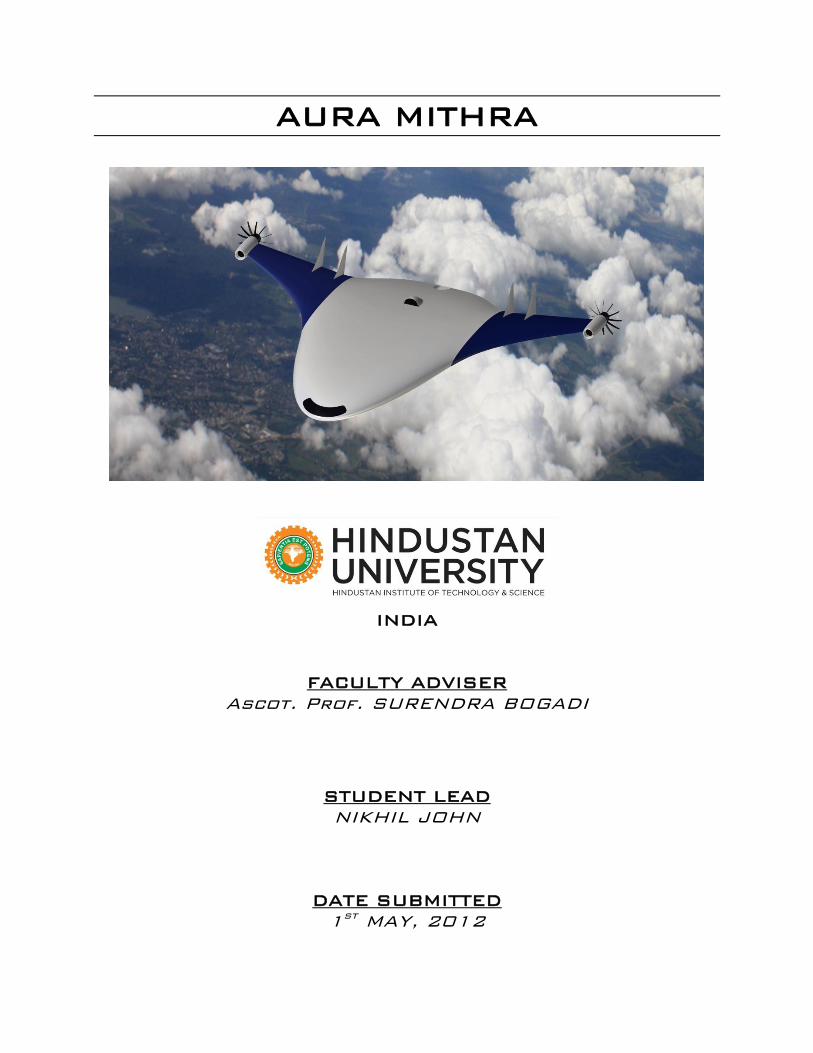
AURA MITHRA
INDIA
FACULTY ADVISER
Ascot. Prof. SURENDRA BOGADI
STUDENT LEAD
NIKHIL JOHN
DATE SUBMITTED
1st MAY, 2012
AURA MITHRA Page 2
THE TEAM
NIKHIL JOHN
3RD YEAR B.E. AERONAUTICAL ENGINEERING STUDENTS, HITS, INDIA Email: [email protected]
ARAVIND SASIKUMAR
3RD YEAR B.E. AERONAUTICAL ENGINEERING STUDENTS, HITS, INDIA Email: [email protected]
MANISH KUMAR
3RD YEAR B.E. AERONAUTICAL ENGINEERING STUDENTS, HITS, INDIA Email:
AURA MITHRA Page 3
ABSTRACT
Aura Mithra is an aircraft designed with the primary aim of reducing fuel
consumption. Noise reduction is also part of the objective. The aircraft mainly
features a Blended Wing Body design. It is powered with three engines-two open
fan engines and one ultra high bypass engine. The two open fan engines are
placed at the wingtips while the ultra high bypass engine is buried in the rear
fuselage. The aircraft is provided with elevators and flaperons. It is also equipped
with technologies such as micro vortex generators and pneumatic landing gear
fairings-all aimed at reducing the drag throughout the mission profile. By
combining all these technologies Aura Mithra is estimated to have an increase in
fuel efficiency by around 93%. It also reduces the noise produced by certain
components without affecting the performance significantly making it less noisier
than conventional aircrafts.
AURA MITHRA Page 4
CONTENTS
1. INTRODUCTION……………………………………………………………………………. 2. THE DESIGN…………………………………………………………………………………..
a. HIGHLIGHTS OF AURA MITHRA…………………………………………….. b. WHY WAS A BWB DESIGN CHOSEN?.................................... c. BODY LAYOUT…………………………………………………………………….. d. BASIC DIMENSIONS…………………………………………………………….. e. WHY DELTA WING INSTEAD OF SWEPTWING?...................... f. THE ENGINES………………………………………………………………………
i. INTRODUCTION………………………………………………………… ii. ADVANTAGES…………………………………………………………….
iii. CHALLENGES…………………………………………………………….. iv. OUR ENGINE CONFIGURATION…………………………………. v. TWO OPENFAN ENGINES……………………………………………
vi. WHY ARE OPEN FAN ENGINES PLACED AT WINGTIPS?.. vii. WINGTIP ENGINE MOUNTING ADVANTAGE………………. viii. THIRD ENGINE…………………………………………………………..
ix. ADVANTAGES OF THE THIRD ENGINE………………………... g. VORTEX GENERATORS………………………………………………………… h. RETRACTABLE LANDING GEAR WITH FAIRING……………………..
i. CHALLENGES…………………………………………………………….. ii. ADVANTAGES…………………………………………………………….
3. SUMMARY AND RESULT………………………………………………………………… a. FEATURES THAT INCREASE THE FUEL EFFICIENCY……………….. b. FEATURES THAT REDUCE NOISE………………………………………….. c. FEATURES THAT CONTRIBUTE TO LIFT………………………………….
4. CONCLUSION……………………………………………………………………………….. 5. REFERENCES………………………………………………………………………………….
5 6 6 7 8 9 9 10 10 10 11 11 12 12 16 16 19 19 20 20 21 22 22 22 23 24 25
AURA MITHRA Page 5
INTRODUCTION
AURA MITHRA is an aircraft designed to make flying more efficient and greener. It
combines many of the well know and proven technologies along with some
innovations blended into one design to make it as efficient as possible.
In this design increasing the fuel efficiency of the aircraft was given the
prime importance followed by noise reduction. Some features in the aircraft also
add on more safety.
CHAPTER 1
AURA MITHRA Page 6
THE DESIGN
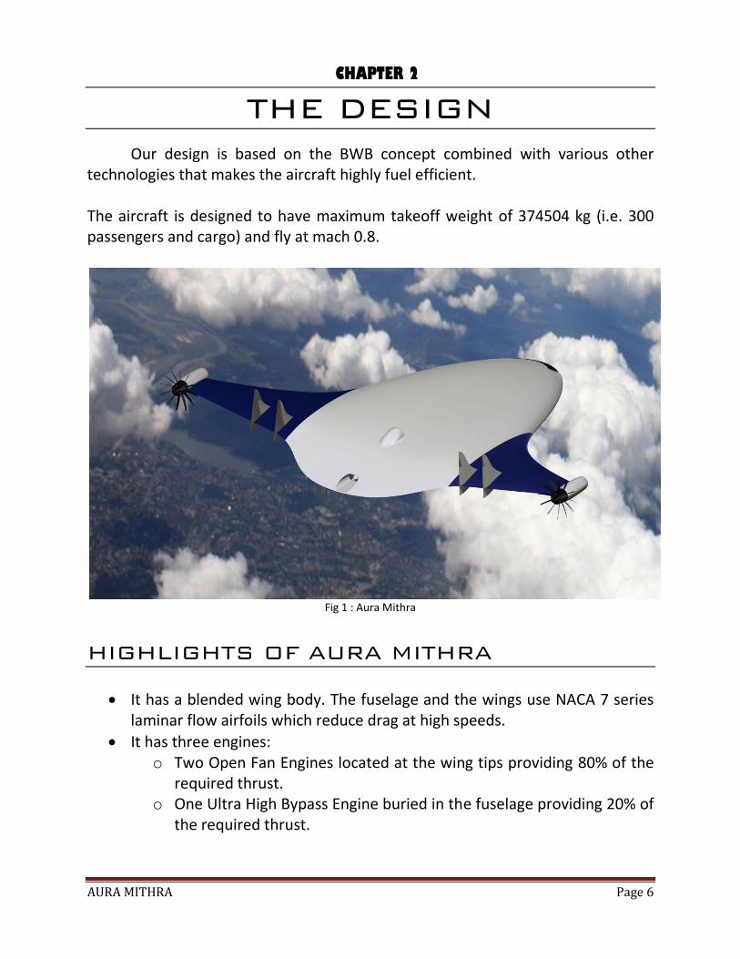
Our design is based on the BWB concept combined with various other technologies that makes the aircraft highly fuel efficient. The aircraft is designed to have maximum takeoff weight of 374504 kg (i.e. 300 passengers and cargo) and fly at mach 0.8.
Fig 1 : Aura Mithra
HIGHLIGHTS OF AURA MITHRA
It has a blended wing body. The fuselage and the wings use NACA 7 series laminar flow airfoils which reduce drag at high speeds.
It has three engines: o Two Open Fan Engines located at the wing tips providing 80% of the
required thrust. o One Ultra High Bypass Engine buried in the fuselage providing 20% of
the required thrust.
CHAPTER 2
AURA MITHRA Page 7
The wings have no swept back. Instead it is designed similar to a delta wing, giving the wings high structural strength at the same time maintaining the required leading edge sweptback angle.
It has four rudders, two on each side. The elevators are placed in the areas in between the two rudders. In this arrangement no gap is formed between the trailing edge of the elevator and the trailing edge of the wing, creating a clean flow.
The centre engine’s exhaust exit is located on the upper surface of the fuselage reducing noise and helps in controlling boundary layer and increase lift during take-off (By vectoring thrust).
The centre engine’s inlet is also located on the upper surface of the fuselage. This helps in boundary layer energizing and increased lift.
The retractable landing gears are designed with pneumatic fairings that can also act as spoilers. This reduces drag while take-off and increases drag while landing.
Why was a Blended Body Design chosen?
Blended Wing Body (BWB) aircrafts has aerofoil shaped fuselage blended into the
wing. Most of the lift is produced by the body while the wing is used to balance it.
In the recent years BWB concepts proved to have vast potential as the
aircrafts of the future.
THEIR ADVANTAGES INCLUDE:
Significant payload advantages in strategic airlift/air freight and aerial
refueling roles.
Structurally Superior.
Reduced empty weight compared to conventional aircrafts (by about 18%).
Reduced noise due to the smooth flow over the blended surface.
Reduced wetted surface area for the same volume of payload.
High values of L/D.
Cheaper to Build (by about 25%).
Cheaper to Operate (by about 32%).
AURA MITHRA Page 8
Requires Lesser Thrust.
Easily matches with the present airport conditions.
All the capabilities of BWB design have already been demonstrated through
various designs such as the SAX (MIT), X-15, Vela Series and many more.
In short a BWB design in general can be considered about 30% more fuel efficient
than conventional designs.
In order to take advantage of the capabilities mentioned above it was
decided to use the BWB concept as the basis of our design also.
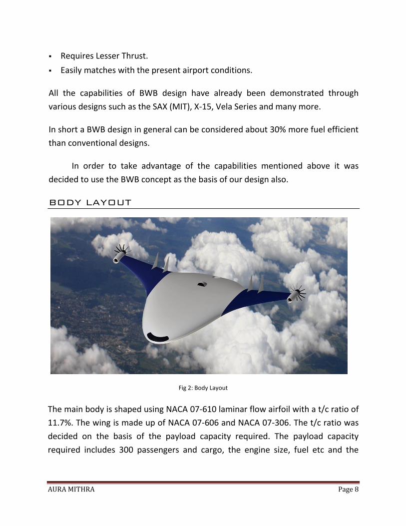
BODY LAYOUT
Fig 2: Body Layout
The main body is shaped using NACA 07-610 laminar flow airfoil with a t/c ratio of
11.7%. The wing is made up of NACA 07-606 and NACA 07-306. The t/c ratio was
decided on the basis of the payload capacity required. The payload capacity
required includes 300 passengers and cargo, the engine size, fuel etc and the
AURA MITHRA Page 9
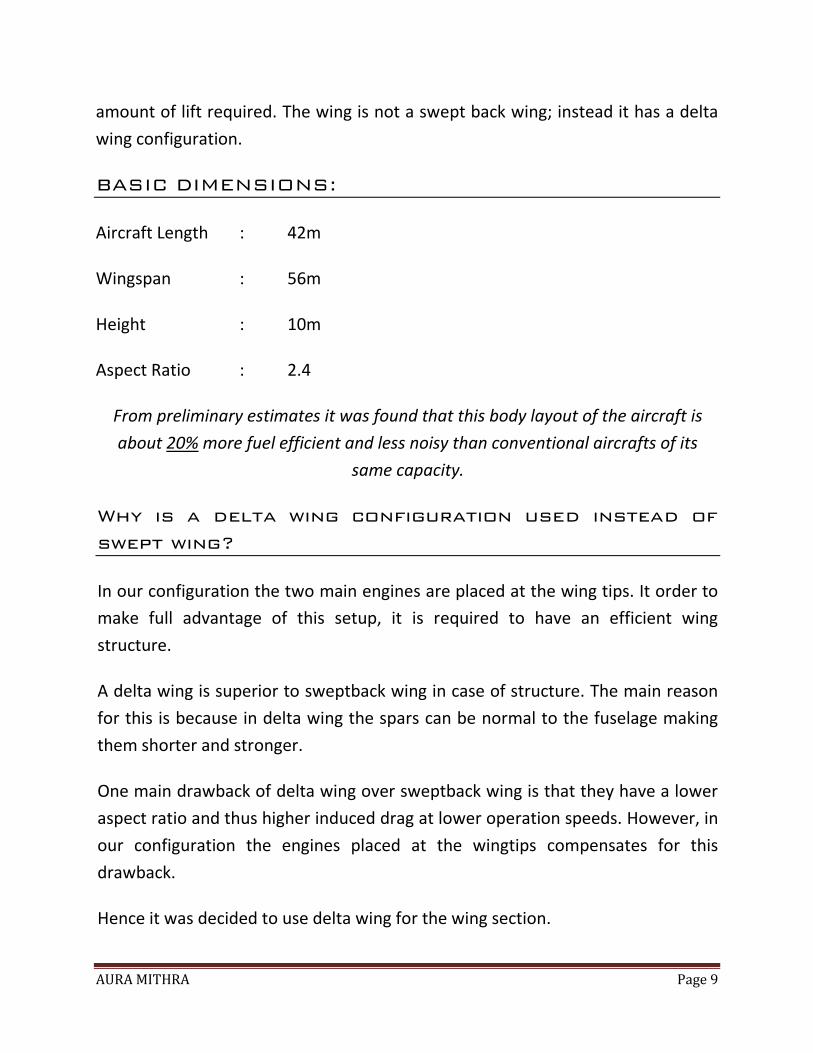
amount of lift required. The wing is not a swept back wing; instead it has a delta
wing configuration.
BASIC DIMENSIONS:
Aircraft Length : 42m
Wingspan : 56m
Height : 10m
Aspect Ratio : 2.4
From preliminary estimates it was found that this body layout of the aircraft is
about 20% more fuel efficient and less noisy than conventional aircrafts of its
same capacity.
Why is a delta wing configuration used instead of
swept wing?
In our configuration the two main engines are placed at the wing tips. It order to
make full advantage of this setup, it is required to have an efficient wing
structure.
A delta wing is superior to sweptback wing in case of structure. The main reason
for this is because in delta wing the spars can be normal to the fuselage making
them shorter and stronger.
One main drawback of delta wing over sweptback wing is that they have a lower
aspect ratio and thus higher induced drag at lower operation speeds. However, in
our configuration the engines placed at the wingtips compensates for this
drawback.
Hence it was decided to use delta wing for the wing section.
AURA MITHRA Page 10
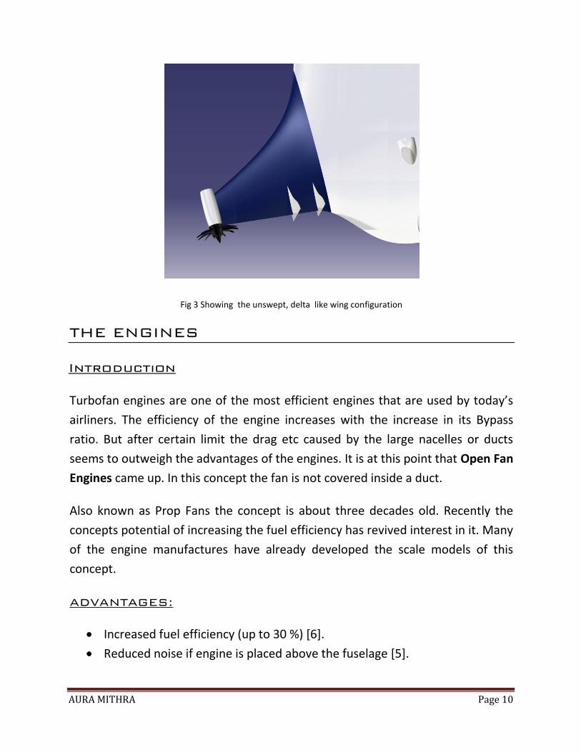
Fig 3 Showing the unswept, delta like wing configuration
THE ENGINES
Introduction
Turbofan engines are one of the most efficient engines that are used by today’s
airliners. The efficiency of the engine increases with the increase in its Bypass
ratio. But after certain limit the drag etc caused by the large nacelles or ducts
seems to outweigh the advantages of the engines. It is at this point that Open Fan
Engines came up. In this concept the fan is not covered inside a duct.
Also known as Prop Fans the concept is about three decades old. Recently the
concepts potential of increasing the fuel efficiency has revived interest in it. Many
of the engine manufactures have already developed the scale models of this
concept.
ADVANTAGES:
Increased fuel efficiency (up to 30 %) [6].
Reduced noise if engine is placed above the fuselage [5].
AURA MITHRA Page 11
CHALLENGES [4]:
Increase in noise due to the absence of duct.
Increase in noise due to the interaction between the counter-rotating
blades.
Installation. Absence of an engine nacelle requires that the fan’s interaction
with the fuselage or wing wakes must be taken into account for improved
performance.
OUR ENGINE CONFIGURATION
We used a total of three engines.
Two Open fan engines providing 70% of thrust.
One Ultra High Bypass engine providing 30% of the thrust.
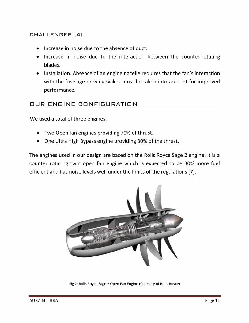
The engines used in our design are based on the Rolls Royce Sage 2 engine. It is a
counter rotating twin open fan engine which is expected to be 30% more fuel
efficient and has noise levels well under the limits of the regulations [7].
Fig 2: Rolls Royce Sage 2 Open Fan Engine (Courtesy of Rolls Royce)
AURA MITHRA Page 12
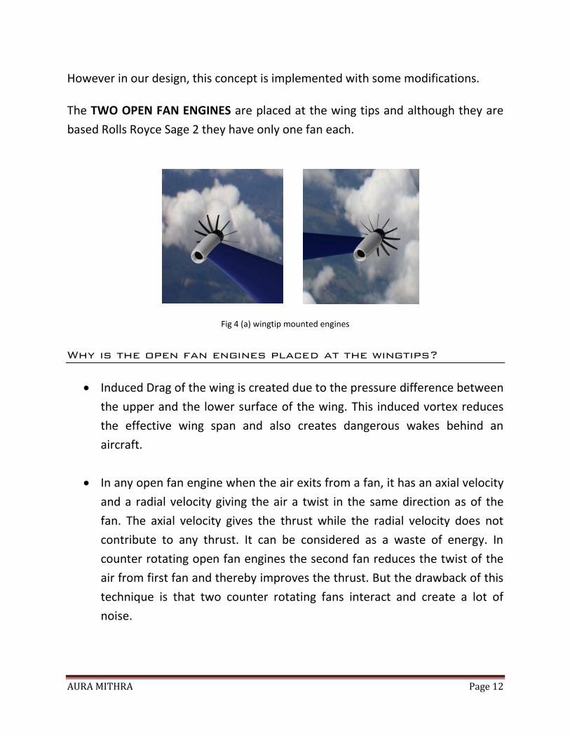
However in our design, this concept is implemented with some modifications.
The TWO OPEN FAN ENGINES are placed at the wing tips and although they are
based Rolls Royce Sage 2 they have only one fan each.
Fig 4 (a) wingtip mounted engines
Why is the open fan engines placed at the wingtips?
Induced Drag of the wing is created due to the pressure difference between
the upper and the lower surface of the wing. This induced vortex reduces
the effective wing span and also creates dangerous wakes behind an
aircraft.
In any open fan engine when the air exits from a fan, it has an axial velocity
and a radial velocity giving the air a twist in the same direction as of the
fan. The axial velocity gives the thrust while the radial velocity does not
contribute to any thrust. It can be considered as a waste of energy. In
counter rotating open fan engines the second fan reduces the twist of the
air from first fan and thereby improves the thrust. But the drawback of this
technique is that two counter rotating fans interact and create a lot of
noise.
AURA MITHRA Page 13
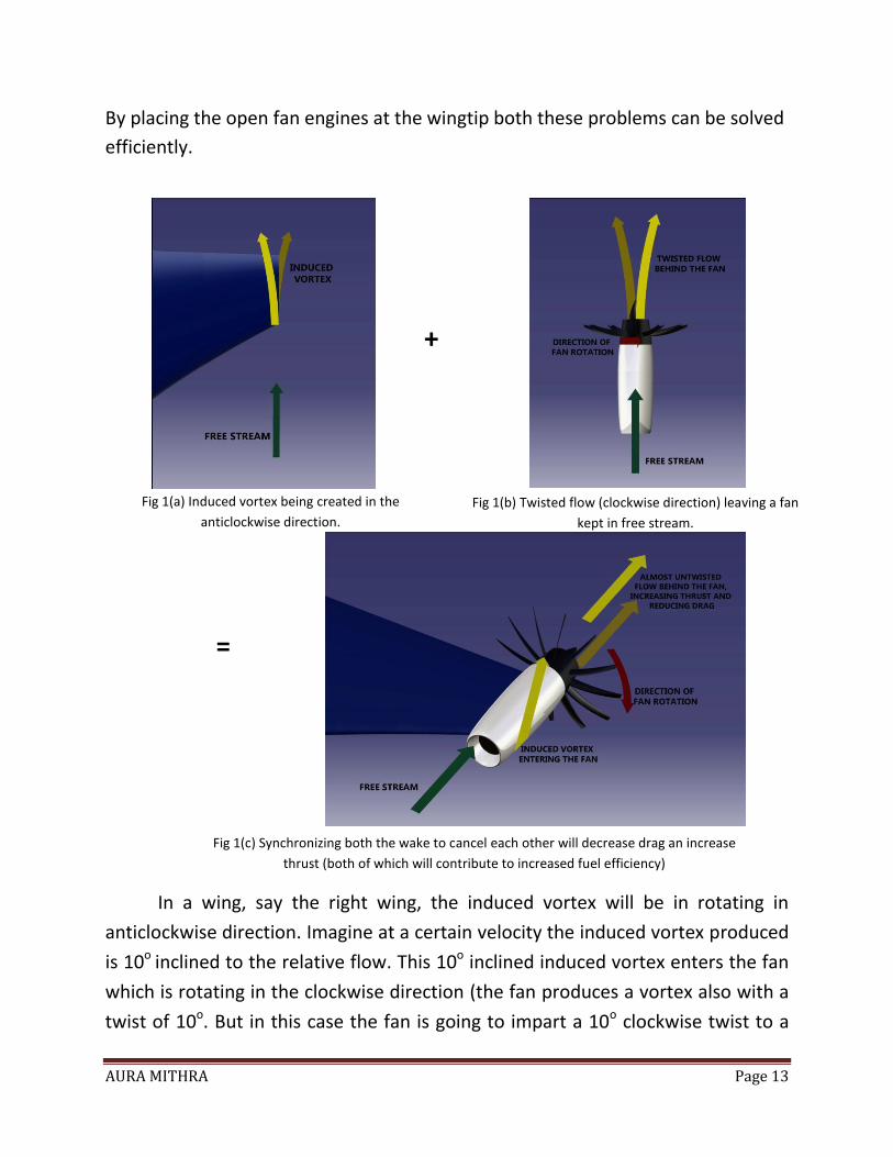
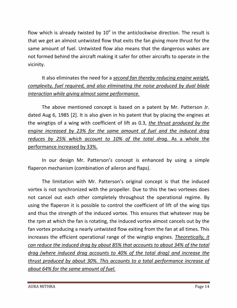
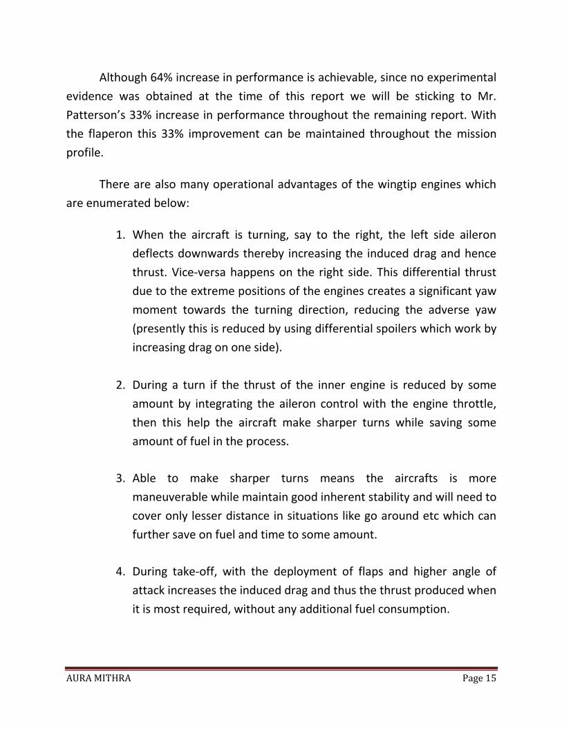
By placing the open fan engines at the wingtip both these problems can be solved
efficiently.
+
=
In a wing, say the right wing, the induced vortex will be in rotating in
anticlockwise direction. Imagine at a certain velocity the induced vortex produced
is 10o inclined to the relative flow. This 10o inclined induced vortex enters the fan
which is rotating in the clockwise direction (the fan produces a vortex also with a
twist of 10o. But in this case the fan is going to impart a 10o clockwise twist to a
Fig 1(a) Induced vortex being created in the
anticlockwise direction.
Fig 1(b) Twisted flow (clockwise direction) leaving a fan
kept in free stream.
Fig 1(c) Synchronizing both the wake to cancel each other will decrease drag an increase
thrust (both of which will contribute to increased fuel efficiency)
AURA MITHRA Page 14
flow which is already twisted by 10o in the anticlockwise direction. The result is
that we get an almost untwisted flow that exits the fan giving more thrust for the
same amount of fuel. Untwisted flow also means that the dangerous wakes are
not formed behind the aircraft making it safer for other aircrafts to operate in the
vicinity.
It also eliminates the need for a second fan thereby reducing engine weight,
complexity, fuel required, and also eliminating the noise produced by dual blade
interaction while giving almost same performance.
The above mentioned concept is based on a patent by Mr. Patterson Jr.
dated Aug 6, 1985 [2]. It is also given in his patent that by placing the engines at
the wingtips of a wing with coefficient of lift as 0.3, the thrust produced by the
engine increased by 23% for the same amount of fuel and the induced drag
reduces by 25% which account to 10% of the total drag. As a whole the
performance increased by 33%.
In our design Mr. Patterson’s concept is enhanced by using a simple
flaperon mechanism (combination of aileron and flaps).
The limitation with Mr. Patterson’s original concept is that the induced
vortex is not synchronized with the propeller. Due to this the two vortexes does
not cancel out each other completely throughout the operational regime. By
using the flaperon it is possible to control the coefficient of lift of the wing tips
and thus the strength of the induced vortex. This ensures that whatever may be
the rpm at which the fan is rotating, the induced vortex almost cancels out by the
fan vortex producing a nearly untwisted flow exiting from the fan at all times. This
increases the efficient operational range of the wingtip engines. Theoretically, it
can reduce the induced drag by about 85% that accounts to about 34% of the total
drag (where induced drag accounts to 40% of the total drag) and increase the
thrust produced by about 30%. This accounts to a total performance increase of
about 64% for the same amount of fuel.
AURA MITHRA Page 15
Although 64% increase in performance is achievable, since no experimental
evidence was obtained at the time of this report we will be sticking to Mr.
Patterson’s 33% increase in performance throughout the remaining report. With
the flaperon this 33% improvement can be maintained throughout the mission
profile.
There are also many operational advantages of the wingtip engines which
are enumerated below:
1. When the aircraft is turning, say to the right, the left side aileron
deflects downwards thereby increasing the induced drag and hence
thrust. Vice-versa happens on the right side. This differential thrust
due to the extreme positions of the engines creates a significant yaw
moment towards the turning direction, reducing the adverse yaw
(presently this is reduced by using differential spoilers which work by
increasing drag on one side).
2. During a turn if the thrust of the inner engine is reduced by some
amount by integrating the aileron control with the engine throttle,
then this help the aircraft make sharper turns while saving some
amount of fuel in the process.
3. Able to make sharper turns means the aircrafts is more
maneuverable while maintain good inherent stability and will need to
cover only lesser distance in situations like go around etc which can
further save on fuel and time to some amount.
4. During take-off, with the deployment of flaps and higher angle of
attack increases the induced drag and thus the thrust produced when
it is most required, without any additional fuel consumption.
AURA MITHRA Page 16
SUMMARY OF THE ADVANTAGES OF WINGTIP ENGINE
MOUNTING:
Reduces induced drag by 25% (by synchronizing about 85%).
Increases thrust produced by engine for the same fuel by 23% (by
synchronizing 30%).
Considerable reduction in noise due to the elimination of the second fan.
Improves the maneuverability while having good degree of inherent
stability.
Increases fuel efficiency by about 33% (will be more with synchronization).
Increase in L/D due to increased effective span.
Produces clean flow over the entire wing unlike in case of conventional
under wing mounting.
The combined drag of the wing plus engine configuration is less for a
wingtip mounting when compared to under wing or over wing mounting,
even without considering the effect of the fan.
So, a BWB design which by itself is 20% more efficient than conventional aircrafts,
combined with an open fan engine, which due to its ultra high bypass ratio is
about 20% more fuel efficient than today’s turbofans, along with the wingtip
engine mounting, which makes it 33% improved performance, will make this
aircraft 73% more efficient and also more silent than conventional airplanes of
today.
The THIRD ULTRA HIGH BYPASS engine which is buried in the rear segment of the
fuselage produces 30% of the required thrust. By burying the engine in the
fuselage the engines ram impact drag and nacelle drag can be significantly
reduced.
AURA MITHRA Page 17
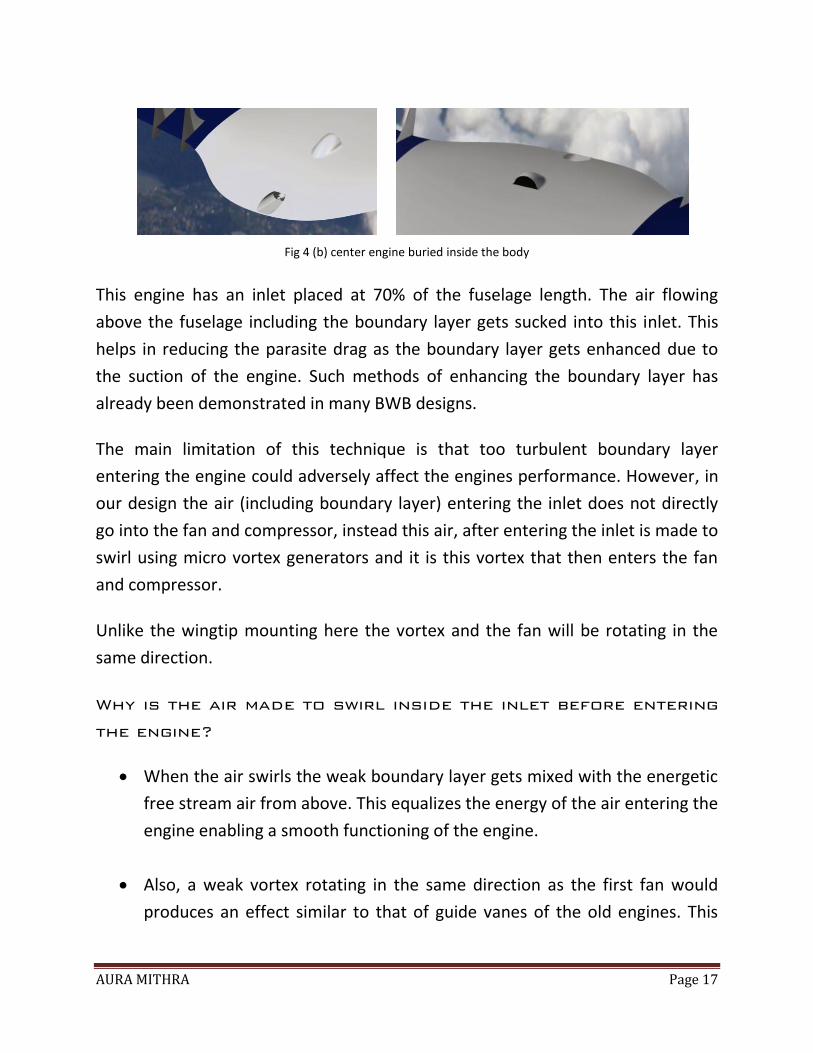
Fig 4 (b) center engine buried inside the body
This engine has an inlet placed at 70% of the fuselage length. The air flowing
above the fuselage including the boundary layer gets sucked into this inlet. This
helps in reducing the parasite drag as the boundary layer gets enhanced due to
the suction of the engine. Such methods of enhancing the boundary layer has
already been demonstrated in many BWB designs.
The main limitation of this technique is that too turbulent boundary layer
entering the engine could adversely affect the engines performance. However, in
our design the air (including boundary layer) entering the inlet does not directly
go into the fan and compressor, instead this air, after entering the inlet is made to
swirl using micro vortex generators and it is this vortex that then enters the fan
and compressor.
Unlike the wingtip mounting here the vortex and the fan will be rotating in the
same direction.
Why is the air made to swirl inside the inlet before entering
the engine?
When the air swirls the weak boundary layer gets mixed with the energetic
free stream air from above. This equalizes the energy of the air entering the
engine enabling a smooth functioning of the engine.
Also, a weak vortex rotating in the same direction as the first fan would
produces an effect similar to that of guide vanes of the old engines. This
AURA MITHRA Page 18
reduces the chance of the first blade to surge without adding the weight or
complexity of an actual guide vane.
In short by creating a swirl inside the inlet before the air enters the engine it is
possible to energize the boundary layer without adversely affecting the engine
performance.
Since the center engine is completely buried in the fuselage it is possible to
significantly reduce noise with the help of mufflers etc. This also permits the use
of counter rotating fan which are highly fuel efficient.
In addition to this the nozzle exit is also located on the upper surface of the
fuselage. This also reduces the noise created by the exit making the aircraft more
silent. The exhaust also acts as a blower and helps in energizing the boundary
layers.
Apart from the drag and noise this arrangement of engine also helps in lift
augmentation.
The air from the upper surface of the aircraft is sucked into the engines inlet. This
suction increases the velocity of flow over the upper surface and thereby lowering
the pressure on the upper surface while the flow over the lower surface remains
the same and hence the pressure. This increased differential pressure gives an
increase in the lift produced by the aircraft.
This is based the concept of the channel wings developed by Mr. William Custer
and others which first came up in the 1940s [3].
Also the surface that is extending from the exit of the nozzle is made in such a
way that it can be deflected like a simple flap (will be termed as nozzle exit flap).
During Take-Off, when this nozzle exit flap is deployed. It vectors the thrust from
the engine downwards due to the coanda effect. This helps the aircraft to
perform shorter take-offs.
AURA MITHRA Page 19
The nozzle exit flap is also designed to serve as the thrust reverses during landing.
SUMMARY OF THE ADVANTAGES OF THE CENTER ENGINE:
Boundary layer energizing and thereby reduction in drag (by around 5%).
Significant reduction in noise due to buried engine and upper surface
nozzle exit.
Lift augmentation due to channel wing concept.
Lift augmentation by thrust vectoring during take-off etc.
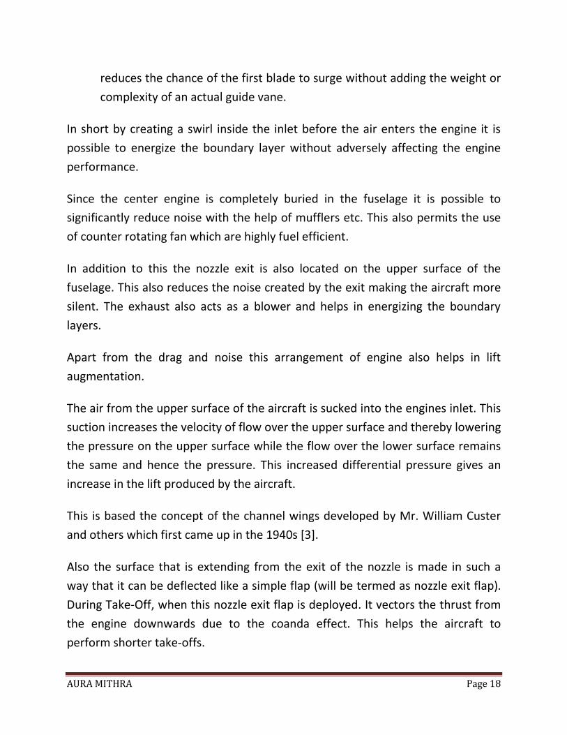
VORTEX GENERATORS
The design also features vortex generators placed along the line as shown in the
figure to avoid flow separation and thereby reduce drag.
The vortex generators proposed to be used in this design are the Micro Vortex
Generators developed by NASA [11]. These vortex generators can reduce
aerodynamic drag by 50%, increase the lift by 10% and increase the L/D as much
as 100%.
For preliminary calculation a 30% reduction in the drag is considered.
Fig 6: The red line indicates the position of the vortex generators
AURA MITHRA Page 20
RETRACTABLE LANDING GEAR WITH FAIRING
Almost all conventional airliners traveling at high subsonic speeds have
retractable landing gear. Landing gears typically produce 4% -7% of the total drag.
When we use a retractable landing gear it eliminates the drag created by the
landing gear completely during cruise. But these landing gears produce lot of drag
during take- off and landing.
Typical retractable landing gear system consists of the landing gear, retraction
mechanism and the doors.
But in our design we opted for a retractable landing gear with fairing as its
advantages outweighed the increase in weight.
Normally fairing is not opted for retractable landing gear due to the following
reasons.
1. It adds more weight.
2. Landing gear will be exposed only for a short duration of time.
These problems are resolved to some extent by the following means:
With the use of pneumatically activated fairing for the wheels. This type of
fairings will be build with the materials used for deicing boots, ram air
parachutes etc with a light frame for support and a mechanism to restore it
after deflation.
The pneumatically activated fairing will not add significant weight to the
system. Being flexible can be easily folded and stowed along with the
landing gear.
The Strut fairing can be made from light weight composite materials.
AURA MITHRA Page 21
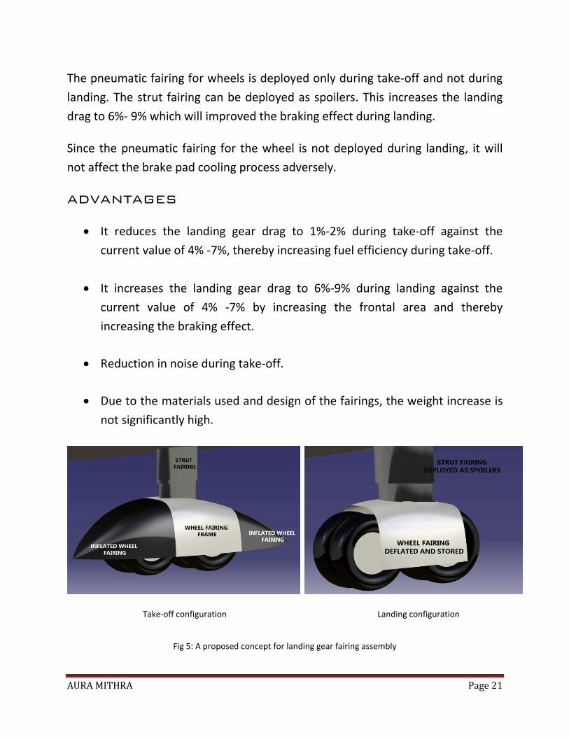
The pneumatic fairing for wheels is deployed only during take-off and not during
landing. The strut fairing can be deployed as spoilers. This increases the landing
drag to 6%- 9% which will improved the braking effect during landing.
Since the pneumatic fairing for the wheel is not deployed during landing, it will
not affect the brake pad cooling process adversely.
ADVANTAGES
It reduces the landing gear drag to 1%-2% during take-off against the
current value of 4% -7%, thereby increasing fuel efficiency during take-off.
It increases the landing gear drag to 6%-9% during landing against the
current value of 4% -7% by increasing the frontal area and thereby
increasing the braking effect.
Reduction in noise during take-off.
Due to the materials used and design of the fairings, the weight increase is
not significantly high.
Take-off configuration Landing configuration
Fig 5: A proposed concept for landing gear fairing assembly
AURA MITHRA Page 22
SUMMARY AND RESULT
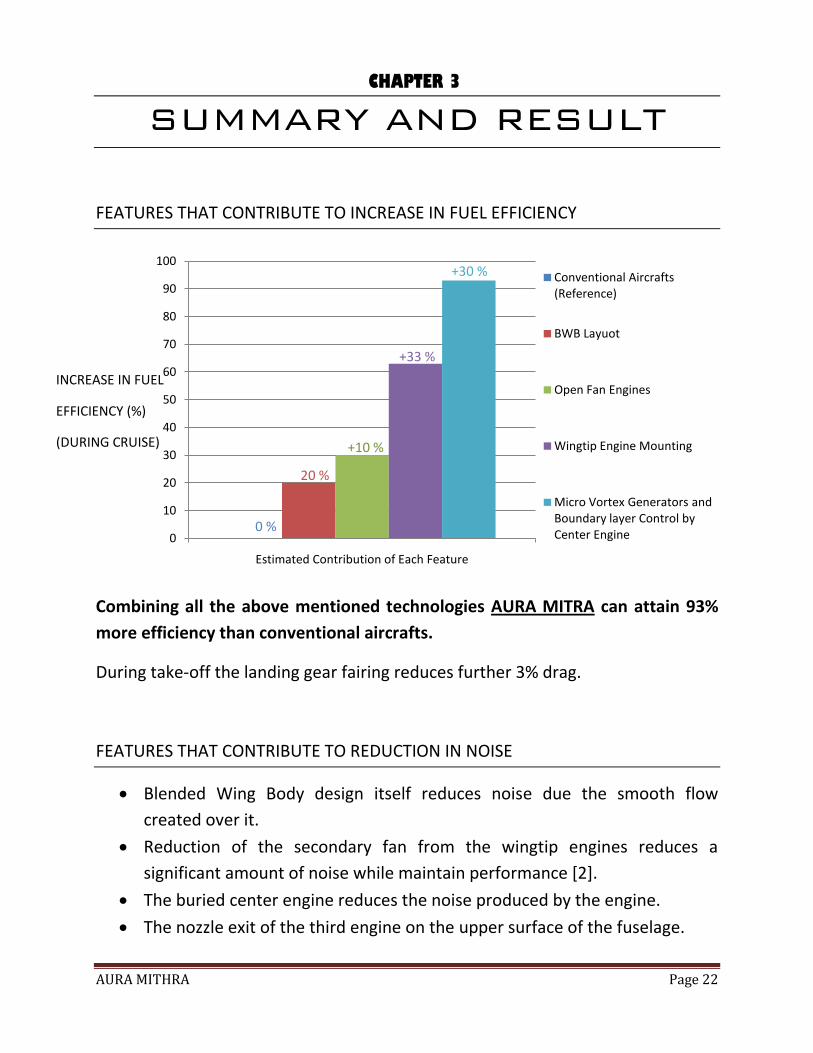
FEATURES THAT CONTRIBUTE TO INCREASE IN FUEL EFFICIENCY
Combining all the above mentioned technologies AURA MITRA can attain 93%
more efficiency than conventional aircrafts.
During take-off the landing gear fairing reduces further 3% drag.
FEATURES THAT CONTRIBUTE TO REDUCTION IN NOISE
Blended Wing Body design itself reduces noise due the smooth flow
created over it.
Reduction of the secondary fan from the wingtip engines reduces a
significant amount of noise while maintain performance [2].
The buried center engine reduces the noise produced by the engine.
The nozzle exit of the third engine on the upper surface of the fuselage.
0
10
20
30
40
50
60
70
80
90
100
Estimated Contribution of Each Feature
Conventional Aircrafts (Reference)
BWB Layuot
Open Fan Engines
Wingtip Engine Mounting
Micro Vortex Generators and Boundary layer Control by Center Engine
INCREASE IN FUEL
EFFICIENCY (%)
(DURING CRUISE)
0 %
20 %
+10 %
+33 %
+30 %
CHAPTER 3
AURA MITHRA Page 23
The landing gear fairing also reduces noise during take of as flow over it
gets smoothened.
A thread like feature at the trailing edge used in SAX to reduce the
aerodynamic noise caused due the mixing of upper and lower surface flow
can be implemented in the design to further reduce noise.
FEATURES THAT CONTRIBUTE TO LIFT
During Cruise
The fuselage produces most of the lift required (around 74%), similar to
other BWBs.
The wings contribute to around 24-25% of the lift.
The Inlet of the center buried engine also contributes to lift (around 2-1%).
During Take-Off
The fuselage
The wings.
The Inlet of the center buried engine’s contribution increases due to low fre
stream velocity
Vectored Thrust from the third engine.
AURA MITHRA Page 24
CONCLUSION
This project although is still in its preliminary stage has proved to be very
successful and the satisfactory.
We were also able to revive some of the forgotten technologies and put them to
proper application.
There is still a lot more room for development. For instance, there are many more
technologies that are implemented in aircrafts like SAX etc that could reduce
noise and improve some more performance if added to AURA MITRA.
Also the estimation of some of the features was done using the minimum values.
A more detailed development can likely improve the present performance.
CHAPTER 4
AURA MITHRA Page 25
REFERENCES
1. Data Sheets of:
A310-300
A330-300
A340-500
A350-1000
A380-800
B747-400
B767-400
B777-200LR
B787-9
2. US Patent no. 4,533,101 by Patterson, Jr. “WINGTIP VORTEX PROPELLER”.(
Aug. 6th, 1985)
3. “Channel Wing as a Potential VTOL/STOL Aero-Vehicle Concept” by Zeki O.
Gokce and Cengiz Camci.
4. “Sustainable and Green Energy” by Mark Pacey, Programme Manager,
Rolls-Royce plc.
5. http://www.dae.mi.th/aero-update/05_Boeing,%20Rolls-
Royce,%20RUAG%20to%20Investigate%20Open-
Fan%20Propulsion%20Technology_EN.htm
6. http://www.psmag.com/business-economics/prop-planes-the-future-of-
eco-friendly-aviation-39649/
7. http://www.rolls-royce.com/sustainability/markets/aviation/
8. http://en.wikipedia.org/wiki/Propfan#Jet_aircraft_fuel_economy
AURA MITHRA Page 26
9. http://en.wikipedia.org/wiki/General_Electric_GE90
10. Drag Reduction by Shock and Boundary Layer Control: Results of the
Project ... By E. Stanewsky
11. http://www.nasa.gov/centers/langley/news/factsheets/Micro-VG.html
12. http://www.geaviation.com/engines/commercial/ge90/ge90-115b.html
13. www.geaviation.com/engines/commercial/ge90/
14. http://www.flightglobal.com/news/articles/whatever-happened-to-
propfans-214520/