fuel system
TRANSCRIPT
03-3
ENGINE FUEL SYSTEMRODIUS 2004.09
1881-01
1881-01FUEL SYSTEM
1. CAUTIONS FOR DI ENGINEThis chapter describes the cautions for DI engine equipped vehicle. This includes the water separation from engine, warning lights, symptoms when engine malfunctioning, causes and actions.
1) DI EngineComparatively conventional diesel engines, DI engine controls the fuel injection and timing electrically, delivers high power and reduces less emission.
2) System Safety ModeWhen a severe failure has been occurred in a vehicle, the system safety mode is activated to protect the system. It reduces the driving force, restricts the engine speed (rpm) and stops engine operation. Refer to “Diagnosis” section in this manual.
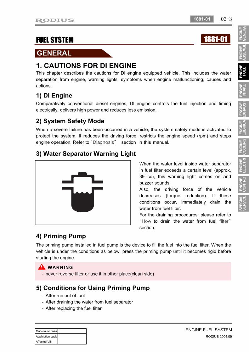
3) Water Separator Warning LightWhen the water level inside water separator in fuel filter exceeds a certain level (approx. 39 cc), this warning light comes on and buzzer sounds.Also, the driving force of the vehicle decreases (torque reduction). If these conditions occur, immediately drain the water from fuel filter.For the draining procedures, please refer to “How to drain the water from fuel filter”
section.
4) Priming PumpThe priming pump installed in fuel pump is the device to fill the fuel into the fuel filter. When the vehicle is under the conditions as below, press the priming pump until it becomes rigid before starting the engine.
5) Conditions for Using Priming PumpAfter run out of fuelAfter draining the water from fuel separatorAfter replacing the fuel filter
---
never reverse filter or use it in other place(clean side)-
03-4
RODIUS 2004.09
1881-01
ENGINE FUEL SYSTEM
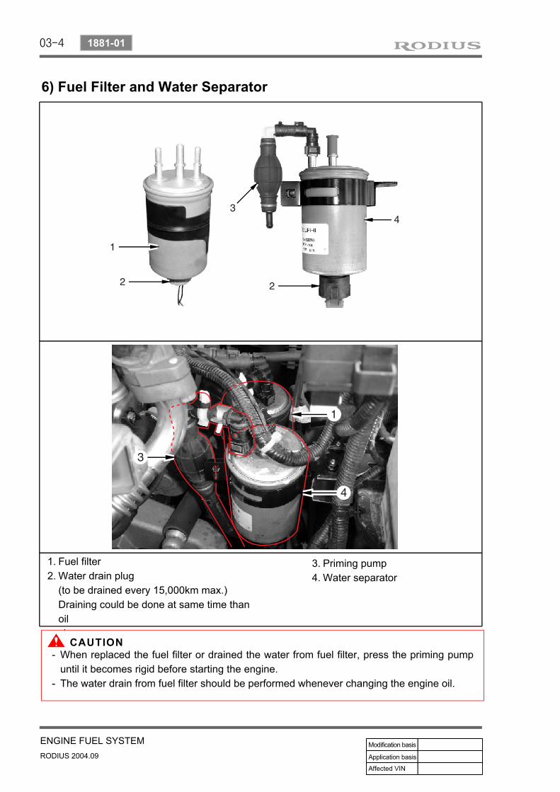
6) Fuel Filter and Water Separator
Fuel filterWater drain plug(to be drained every 15,000km max.)Draining could be done at same time than oilchange
1.2.
Priming pumpWater separator
3.4.
When replaced the fuel filter or drained the water from fuel filter, press the priming pump until it becomes rigid before starting the engine.The water drain from fuel filter should be performed whenever changing the engine oil.
-
-

03-5
ENGINE FUEL SYSTEMRODIUS 2004.09
1881-01
7) Draining the Water From Fuel FilterPlace the water container under the fuel filter.
1.
Turn the drain plug (2) to “A” direction to drain the water.2.
Wait until a certain amount of fuel gets out from the port, then turn the drain plug to “B” direction to tighten it.
3.
Press the priming pump until it becomes rigid.
4.
Start the engine and check the conditions.5.
If the priming pump is not properly operated, air may get into the fuel line. It may cause starting problem or fuel system problem. Make sure to perform the job in step 4.
-
Be careful not to be injured bysurrounding equipment during the working procedures.
-

03-6
RODIUS 2004.09
1881-01
ENGINE FUEL SYSTEM
8) Draining the Water From Fuel Filter for General Area
1. Fuel filter2. Priming pump3. Water separator
4. Drain plug5. Connector
Place the water container under the fuel filter & water separator.Disconnect the connector under the drain plug of the water separator.Turn both drain plugs to “A” direction to drain the water.Wait until a certain amount of fuel gets out from the port, then turn the both drain plugs to “B” direction to tighten it.
1.
2.
3.
4.
Be careful not to be injured bysurrounding equipment during the working procedures.
-
Engage the connector under the drain plug and press the priming pump until it becomes rigid.Start the engine and check the onditions.Clear the fault code of ECU with SCAN-Tools.
4.
5.6.
If the priming pump is not properly operated, air may get into the fuel line. It may cause starting problem or fuel system problem. Make sure to perform the job in step 4.
-

03-7
ENGINE FUEL SYSTEMRODIUS 2004.09
1881-01
1. ELECTRONIC CONTROL OF FUEL SYSTEM
According to input signals from various sensors, engine ECU calculates driver’s demand (position of the accelerator pedal) and then controls overall operating performance of engine and vehicle on that time.ECU receives signals from sensors via data line and then performs effective engine air-fuel ratio controls based on those signals. Engine speed is measured by crankshaft speed (position) sensor and camshaft speed (position) sensor determines injection order and ECU detects driver’s pedal position (driver’s demand) through electrical signal that is generated by variable resistance changes in accelerator pedal sensor. Air flow (hot film) sensor detects intake air volume and sends the signals to ECU. Especially, the engine ECU controls the air-fuel ratio by recognizing instant air volume changes from air flow sensor to decrease the emissions (EGR valve control). Furthermore, ECU uses signals from coolant temperature sensor and air temperature sensor, booster pressure sensor and atmospheric pressure sensor as compensation signal to respond to injection starting, pilot injection set values, various operations and variables.
System compositionHigh pressure fuel pumpFuel injector
--
Fuel railElectronic control unit(ECU)
--
Fuel pressure sensorOther sensors and actuators
--
Supply line
Return line
ECU connecting line

03-8
RODIUS 2004.09
1881-01
ENGINE FUEL SYSTEM
Fuel Line System
Fuel route
2. COMPOSITION OF FUEL SYSTEMComponents in fuel system are designed to generate and distribute high pressure, and they are controlled electronically by engine ECU. Accordingly, fuel system is completely different from injection pump type fuel supply system on the conventional Diesel engine. The fuel injection system in common rail engine is composed of transfer pressure section that transfers fuel in low pressure, high pressure section that transfers fuel in high pressure and ECU control section.
High pressure pipe
Common rail
Fuel pressuresensor
Priming pump
Fuel pump(High pressure pump, transfer pump)
Fuel filter
InjectorD20DT: 4 EAD27DT: 5 EA

03-9
ENGINE FUEL SYSTEMRODIUS 2004.09
1881-01
3. HYDRAULIC CYCLE IN FUEL LINE (TRANSFER AND HIGH PRESSURE LINE)
High pressure supply line
Transfer pressure supply
line Return line

03-10
RODIUS 2004.09
1881-01
ENGINE FUEL SYSTEM
4. COMPONENTS OF LOW PRESSURE TRANSFER LINELow pressure stage is to supply sufficient fuel to high pressure section and components are as below.
Fuel tank (including strainer)Hand priming pumpFuel filterTransfer pumpOther low pressure fuel hoses
-----
1) Fuel tankFuel tank is made of anti-corrosion material and its allowable pressure is 2 times of operating pressure (more than min. 0.3 bar). It has protective cap and safety valve to prevent excessive pressure building. Also, to supply fuel smoothly, it has structure to prevent fuel from leaking in shocks, slopes and corners and.
If fuel runs out during driving or air gets into fuel line after fuel filter replacement, it maycause poor engine starting or damage to each component. Therefore, the hand priming pump is installed to bleed air from transfer line.When the vehicle is under the conditions as below, press the priming pump until it becomes rigid before starting the engine.
2) Priming pump
After run out of fuelAfter draining the water from fuel separatorAfter replacing the fuel filter
---
Press the priming pump until it becomes rigid before starting the engine.

03-11
ENGINE FUEL SYSTEMRODIUS 2004.09
1881-01
It requires more purified fuel supply than conventional diesel engine. If there are foreign materials in the fuel, fuel system including pump components, delivery valveand injector nozzles may be damaged.Fuel filter purifies fuel before it reaches to high pressure pump to help proper operations in high pressure pump.And more, it separates water from fuel to prevent water from getting into FIE system (high pressure line).
3) Fuel filter
4) Transfer PumpThe transfer pump is included in the housing of the high pressure pump. The transfer pump is the volumetric blade type pump. To deliver the continuously required fuel volume, the pump transfers fuel from the fuel tank to high pressure pump.

03-12
RODIUS 2004.09
1881-01
ENGINE FUEL SYSTEM
5. COMPONENTS OF HIGH PRESSURE TRANSFER LINEIn the high pressure section, sufficient fuel pressure that injectors requires will be generated and stored. The components are as below:
High pressure pumpRail pressure sensorPressure limit valveCommon railHigh pressure pipeInjectorFuel pressure regulating valve (IMV)
-------
This is plunger pump that generates high pressure and driven by crankshaft with timing chain. The high pressure pump increases system pressure of fuel to approx.1,600 bar and this compressed fuel is transferred to high pressure accumulator (common rail) in tube through high pressure line.
1) High pressure pump(including IMV and limit valve)
It stores fuel transferred from high pressure pump and also stores actual high pressure of fuel. Even though the injectors inject fuel from the rail, the fuel pressure in the rail is maintained to a specific value. It is because the effect of accumulator is increased byunique elasticity of fuel. Fuel pressure is measured by rail pressure sensor.And the fuel pressure regulating valve (IMV,Inlet Metering Valve) included in high pressure pump housing keeps pressure to a desired level.
2) Common Rail(Including Pressure Sensor)

03-13
ENGINE FUEL SYSTEMRODIUS 2004.09
1881-01
3) High pressure pipe (fuel pipe)Fuel line transfers high pressure fuel. Accordingly, it is made of steel to endure intermittent high frequency pressure changes that occur under maximum system pressure and injection stops. Injection lines between rail and injectors are all in the same length; it means the lengths between the rail and each injector are the same and the differences in length are compensated byeach bending.
No.1 and 3 cylinder No. 5 cylinder
No.2 and 4 cylinder
4) InjectorsThe fuel injection device is composed of electrical solenoid valve, needle and nozzle and controlled by engine ECU. The injector nozzle opens when solenoid valve is activated to directly inject the fuel into combustion chamber in engine. When injector nozzle is open, remaining fuel after injection returns to fuel tank through return line.Pressure limit valve, fuel returned by low pressure and fuel used for high pressure pump lubrication also return to fuel tank through return line.
5) Fuel filter replacementFuel filter change interval: every 30,000 kmWater separation interval: every 10,000 km (same with engine oil change interval)Never reuse the removed fuel filter
---

03-14
RODIUS 2004.09
1881-01
ENGINE FUEL SYSTEM
7) ECU Wiring Diagram