service bulletin - icon aircraft
TRANSCRIPT
2141 ICON Way, Vacaville, CA 95688 ‐ Tel: 707.564.4000 – www.iconaircraft.com
SERVICE BULLETIN SB‐092718 REV B
Confidentiality Note: The information contained in this document is confidential. Any dissemination, distribution, or copy of this document, in whole or in part, is strictly prohibited without prior written authorization by ICON Aircraft Inc.
DATE ISSUED: 5/17/2021 DATE EFFECTIVE: 5/31/2021 SUPERSEDES NOTICE: SB-092718 Rev A SUBJECT: Fuel level sensor gasket
AIRCRAFT AFFECTED: MODEL: ICON A5
S/N: 00001-00028, 00030-00037, 00040, 00046, 00049, 00051-00053, 00126-00131
REQUIRED ACTION: Inspect fuel level sensor for non-conformance. Replace non-conforming units.
TIME OF COMPLIANCE: Next Annual Condition Inspection or 100 hr inspection, from the
effective date above, or prior to next flight if fuel smell is detected inside cockpit. If compliance with previous version of this as already been completed, no addition inspections are required.
REVISION HISTORY: A- Initial Release B- Expand Affected Serial Numbers to ASN 00126-00131
PURPOSE: ICON is committed to designing, manufacturing, delivering, and supporting a high-quality Light Sport Aircraft, providing a level of safety well beyond expectations. During testing it was discovered that the fuel system could be susceptible to a small fuel leak if fuel level sensor installed has a non-conformance condition where a gasket is installed in the incorrect location. Replacement of the fuel level sensor is required to correct the non-conforming condition. The purpose of this Service Bulletin is to provide instructions on inspecting the fuel level sensor for this non-conformance and removing and replacing the fuel level sensor if necessary. WARRANTY: ICON Certified Service Providers: Please submit an invoice for warranty reimbursement for labor and parts on completion of this service bulletin. Please reference service bulletin number SB-092718-B.
1. 2-man hours of labor for disassembly, install of hardware, and reassembly.
2141 ICON Way, Vacaville, CA 95688 ‐ Tel: 707.564.4000 – www.iconaircraft.com
SERVICE BULLETIN SB‐092718 REV B
ICA009718-C PAGE 2 of 15
PARTS LIST:
Applicable Fuel Tank Part Number Description Quantity Rotomolded & Bladder
ICA011319 PROBE, FUEL LEVEL SENSOR 1
Rotomolded & Bladder
ICA012903 GASKET, FUEL SENSOR 1
Rotomolded ICA011512 GASKET, ACCESS PLATE, FUEL TANK 1 Rotomolded TY23MX CABLE-TIE, NYLON 6-6, 18LB, TY-RAP 1 Rotomolded & Bladder
TY24MX CABLE-TIE, NYLON 6-6, 30LB, 5.50, TY-RAP 4
Rotomolded & Bladder
TT-I-735A or equivalent
ISOPROPYL ALCOHOL A/N
Rotomolded ICA012861 SEALANT, GASKET, FUEL RESISTANT A/R Rotomolded LOCTITE 243 THREADLOCKER, PRIMERLESS, OIL TOL,
REMOVABLE MED STR, BLUE A/N
Instructions: Special tools, fixtures, or test equipment:
1. A suitable length of AN-6 fuel hose with a AN-6 male flare fitting at one end.
INSPECTION: 1. It is permissible to disassemble the aircraft as required to permit accessibility, inspection,
adjustment, maintenance, and repair in accordance with the latest release of the Aircraft Maintenance Manual, ICA000833.
a. Remove baggage floor. b. Remove seat backs as needed.
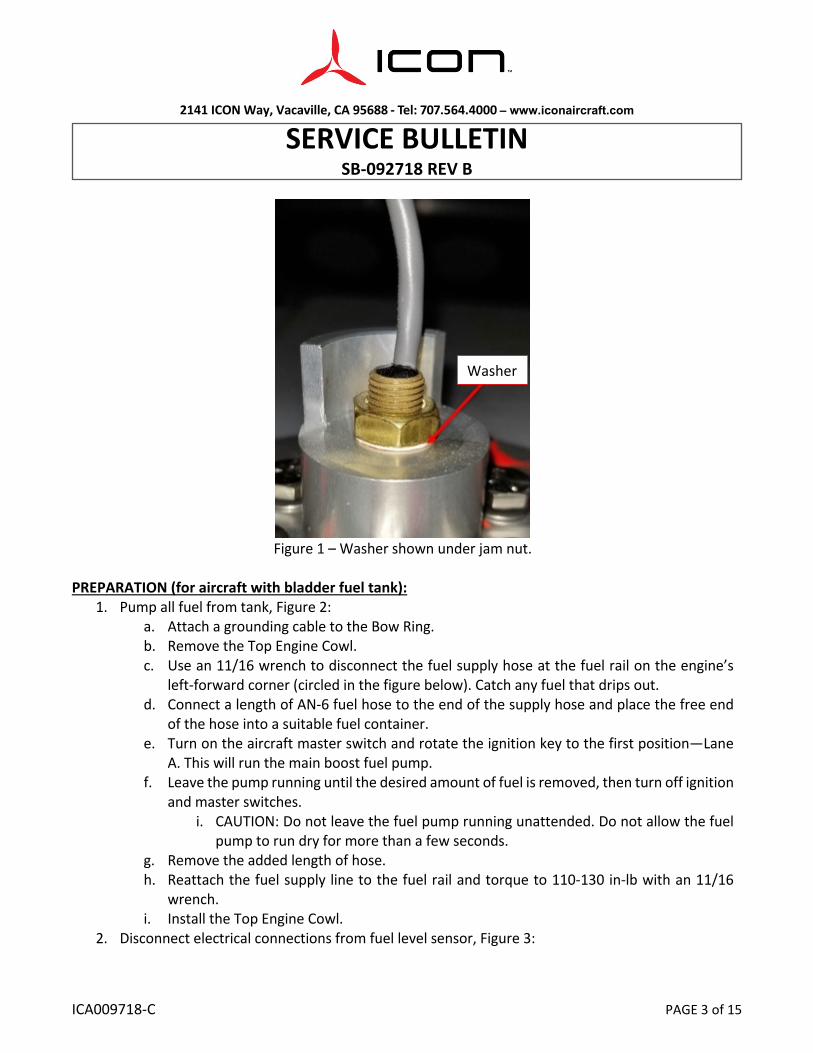
2. Visually inspect the top of the PROBE, FUEL LEVEL SENSOR for a washer underneath the jam nut, Figure 1:
a. If there is no washer underneath the jam nut, no further action is required. Re-install the interior panels.
b. If there is a washer underneath the jam nut, this is a non-conforming fuel level sensor. Proceed to preparation and installation instructions.
2141 ICON Way, Vacaville, CA 95688 ‐ Tel: 707.564.4000 – www.iconaircraft.com
SERVICE BULLETIN SB‐092718 REV B
ICA009718-C PAGE 3 of 15
Figure 1 – Washer shown under jam nut.
PREPARATION (for aircraft with bladder fuel tank):
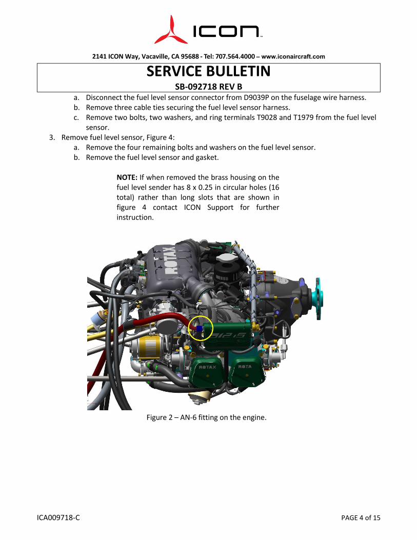
1. Pump all fuel from tank, Figure 2: a. Attach a grounding cable to the Bow Ring. b. Remove the Top Engine Cowl. c. Use an 11/16 wrench to disconnect the fuel supply hose at the fuel rail on the engine’s
left-forward corner (circled in the figure below). Catch any fuel that drips out. d. Connect a length of AN-6 fuel hose to the end of the supply hose and place the free end
of the hose into a suitable fuel container. e. Turn on the aircraft master switch and rotate the ignition key to the first position—Lane
A. This will run the main boost fuel pump. f. Leave the pump running until the desired amount of fuel is removed, then turn off ignition
and master switches. i. CAUTION: Do not leave the fuel pump running unattended. Do not allow the fuel
pump to run dry for more than a few seconds. g. Remove the added length of hose. h. Reattach the fuel supply line to the fuel rail and torque to 110-130 in-lb with an 11/16
wrench. i. Install the Top Engine Cowl.
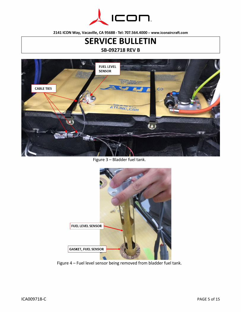
2. Disconnect electrical connections from fuel level sensor, Figure 3:
Washer
2141 ICON Way, Vacaville, CA 95688 ‐ Tel: 707.564.4000 – www.iconaircraft.com
SERVICE BULLETIN SB‐092718 REV B
ICA009718-C PAGE 4 of 15
a. Disconnect the fuel level sensor connector from D9039P on the fuselage wire harness. b. Remove three cable ties securing the fuel level sensor harness. c. Remove two bolts, two washers, and ring terminals T9028 and T1979 from the fuel level
sensor. 3. Remove fuel level sensor, Figure 4:
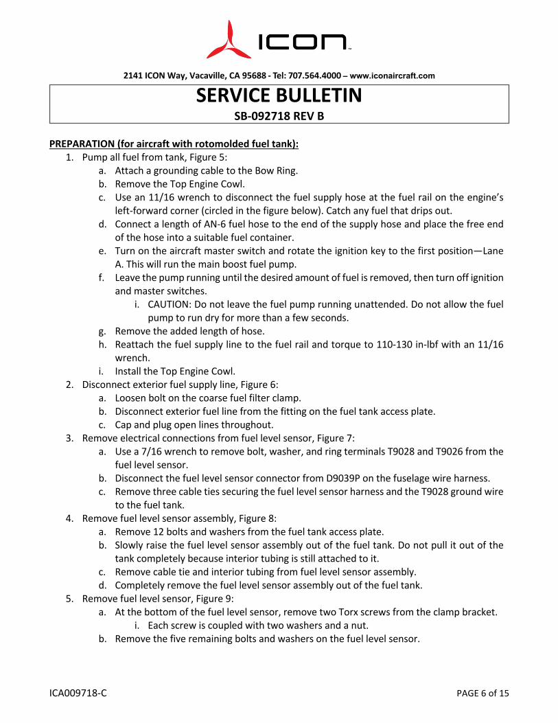
a. Remove the four remaining bolts and washers on the fuel level sensor. b. Remove the fuel level sensor and gasket.
NOTE: If when removed the brass housing on the fuel level sender has 8 x 0.25 in circular holes (16 total) rather than long slots that are shown in figure 4 contact ICON Support for further instruction.
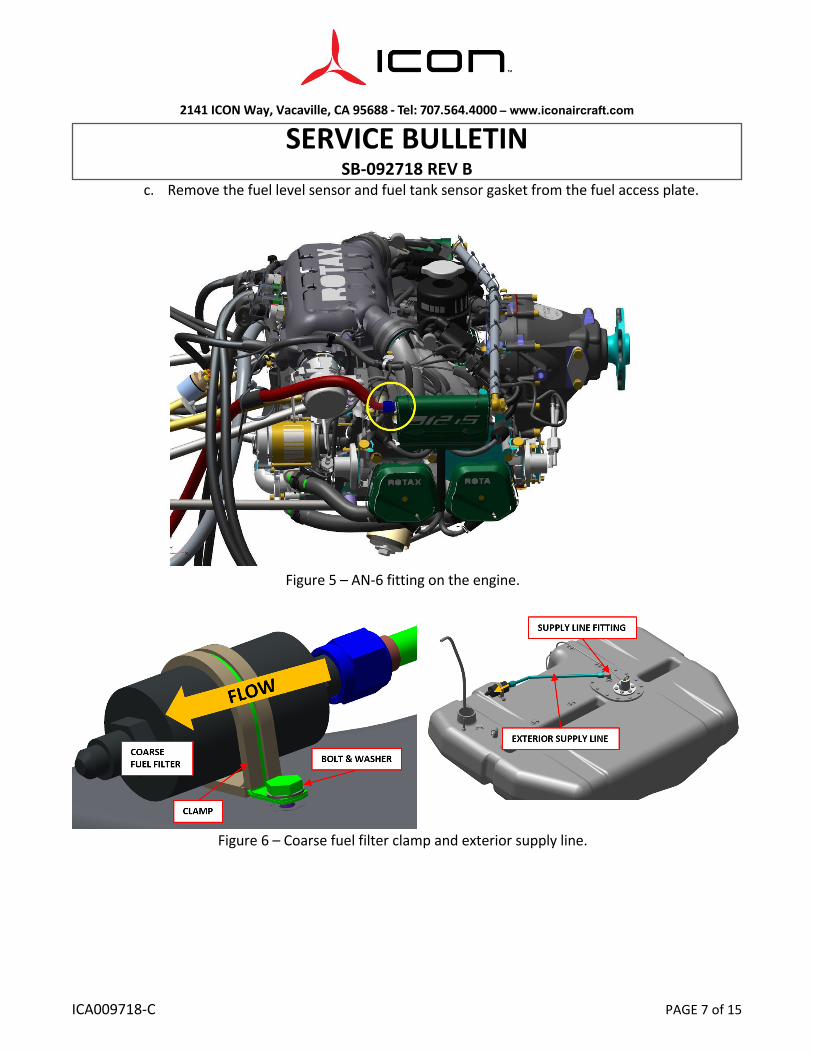
Figure 2 – AN-6 fitting on the engine.
2141 ICON Way, Vacaville, CA 95688 ‐ Tel: 707.564.4000 – www.iconaircraft.com
SERVICE BULLETIN SB‐092718 REV B
ICA009718-C PAGE 5 of 15
Figure 3 – Bladder fuel tank.
Figure 4 – Fuel level sensor being removed from bladder fuel tank.
2141 ICON Way, Vacaville, CA 95688 ‐ Tel: 707.564.4000 – www.iconaircraft.com
SERVICE BULLETIN SB‐092718 REV B
ICA009718-C PAGE 6 of 15
PREPARATION (for aircraft with rotomolded fuel tank):
1. Pump all fuel from tank, Figure 5: a. Attach a grounding cable to the Bow Ring. b. Remove the Top Engine Cowl. c. Use an 11/16 wrench to disconnect the fuel supply hose at the fuel rail on the engine’s
left-forward corner (circled in the figure below). Catch any fuel that drips out. d. Connect a length of AN-6 fuel hose to the end of the supply hose and place the free end
of the hose into a suitable fuel container. e. Turn on the aircraft master switch and rotate the ignition key to the first position—Lane
A. This will run the main boost fuel pump. f. Leave the pump running until the desired amount of fuel is removed, then turn off ignition
and master switches. i. CAUTION: Do not leave the fuel pump running unattended. Do not allow the fuel
pump to run dry for more than a few seconds. g. Remove the added length of hose. h. Reattach the fuel supply line to the fuel rail and torque to 110-130 in-lbf with an 11/16
wrench. i. Install the Top Engine Cowl.
2. Disconnect exterior fuel supply line, Figure 6: a. Loosen bolt on the coarse fuel filter clamp. b. Disconnect exterior fuel line from the fitting on the fuel tank access plate. c. Cap and plug open lines throughout.
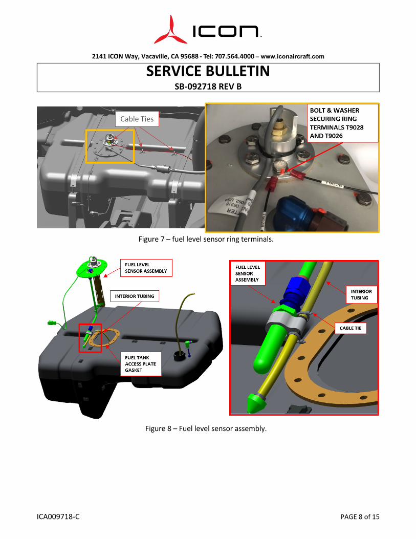
3. Remove electrical connections from fuel level sensor, Figure 7: a. Use a 7/16 wrench to remove bolt, washer, and ring terminals T9028 and T9026 from the
fuel level sensor. b. Disconnect the fuel level sensor connector from D9039P on the fuselage wire harness. c. Remove three cable ties securing the fuel level sensor harness and the T9028 ground wire
to the fuel tank. 4. Remove fuel level sensor assembly, Figure 8:
a. Remove 12 bolts and washers from the fuel tank access plate. b. Slowly raise the fuel level sensor assembly out of the fuel tank. Do not pull it out of the
tank completely because interior tubing is still attached to it. c. Remove cable tie and interior tubing from fuel level sensor assembly. d. Completely remove the fuel level sensor assembly out of the fuel tank.
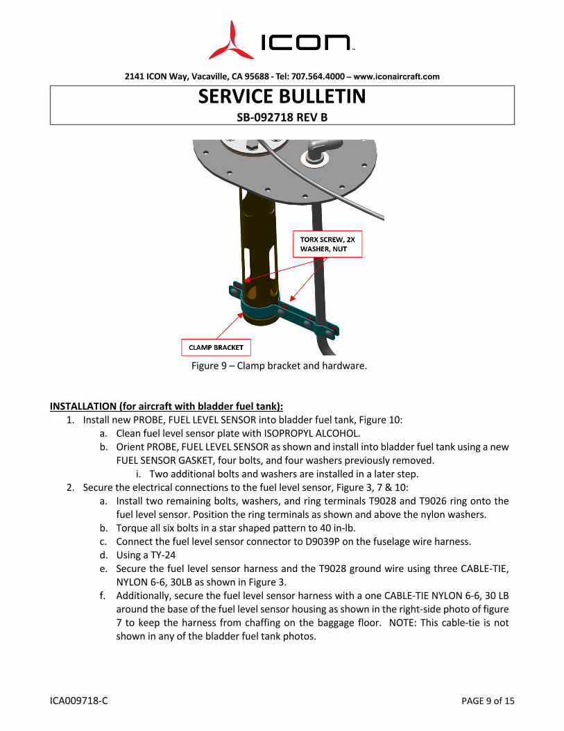
5. Remove fuel level sensor, Figure 9: a. At the bottom of the fuel level sensor, remove two Torx screws from the clamp bracket.
i. Each screw is coupled with two washers and a nut. b. Remove the five remaining bolts and washers on the fuel level sensor.
2141 ICON Way, Vacaville, CA 95688 ‐ Tel: 707.564.4000 – www.iconaircraft.com
SERVICE BULLETIN SB‐092718 REV B
ICA009718-C PAGE 7 of 15
c. Remove the fuel level sensor and fuel tank sensor gasket from the fuel access plate.
Figure 5 – AN-6 fitting on the engine.
Figure 6 – Coarse fuel filter clamp and exterior supply line.
2141 ICON Way, Vacaville, CA 95688 ‐ Tel: 707.564.4000 – www.iconaircraft.com
SERVICE BULLETIN SB‐092718 REV B
ICA009718-C PAGE 8 of 15
Figure 7 – fuel level sensor ring terminals.
Figure 8 – Fuel level sensor assembly.
Cable Ties
2141 ICON Way, Vacaville, CA 95688 ‐ Tel: 707.564.4000 – www.iconaircraft.com
SERVICE BULLETIN SB‐092718 REV B
ICA009718-C PAGE 9 of 15
Figure 9 – Clamp bracket and hardware.
INSTALLATION (for aircraft with bladder fuel tank):
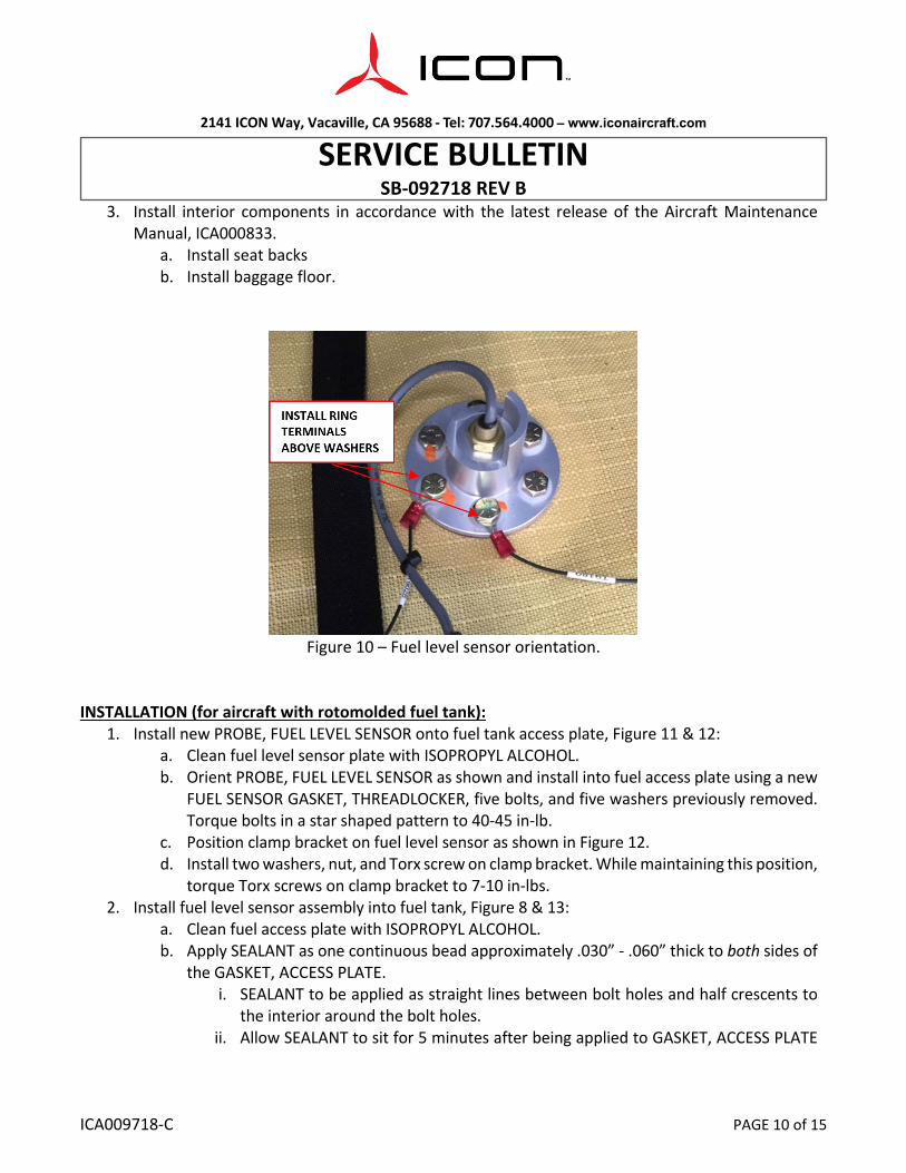
1. Install new PROBE, FUEL LEVEL SENSOR into bladder fuel tank, Figure 10: a. Clean fuel level sensor plate with ISOPROPYL ALCOHOL. b. Orient PROBE, FUEL LEVEL SENSOR as shown and install into bladder fuel tank using a new
FUEL SENSOR GASKET, four bolts, and four washers previously removed. i. Two additional bolts and washers are installed in a later step.
2. Secure the electrical connections to the fuel level sensor, Figure 3, 7 & 10: a. Install two remaining bolts, washers, and ring terminals T9028 and T9026 ring onto the
fuel level sensor. Position the ring terminals as shown and above the nylon washers. b. Torque all six bolts in a star shaped pattern to 40 in-lb. c. Connect the fuel level sensor connector to D9039P on the fuselage wire harness. d. Using a TY-24 e. Secure the fuel level sensor harness and the T9028 ground wire using three CABLE-TIE,
NYLON 6-6, 30LB as shown in Figure 3. f. Additionally, secure the fuel level sensor harness with a one CABLE-TIE NYLON 6-6, 30 LB
around the base of the fuel level sensor housing as shown in the right-side photo of figure 7 to keep the harness from chaffing on the baggage floor. NOTE: This cable-tie is not shown in any of the bladder fuel tank photos.
2141 ICON Way, Vacaville, CA 95688 ‐ Tel: 707.564.4000 – www.iconaircraft.com
SERVICE BULLETIN SB‐092718 REV B
ICA009718-C PAGE 10 of 15
3. Install interior components in accordance with the latest release of the Aircraft Maintenance Manual, ICA000833.
a. Install seat backs b. Install baggage floor.
Figure 10 – Fuel level sensor orientation.
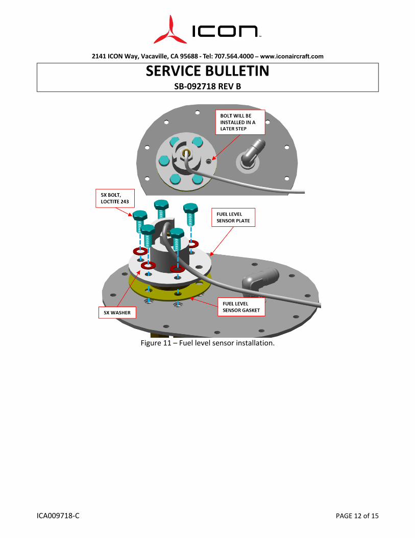
INSTALLATION (for aircraft with rotomolded fuel tank): 1. Install new PROBE, FUEL LEVEL SENSOR onto fuel tank access plate, Figure 11 & 12:
a. Clean fuel level sensor plate with ISOPROPYL ALCOHOL. b. Orient PROBE, FUEL LEVEL SENSOR as shown and install into fuel access plate using a new
FUEL SENSOR GASKET, THREADLOCKER, five bolts, and five washers previously removed. Torque bolts in a star shaped pattern to 40-45 in-lb.
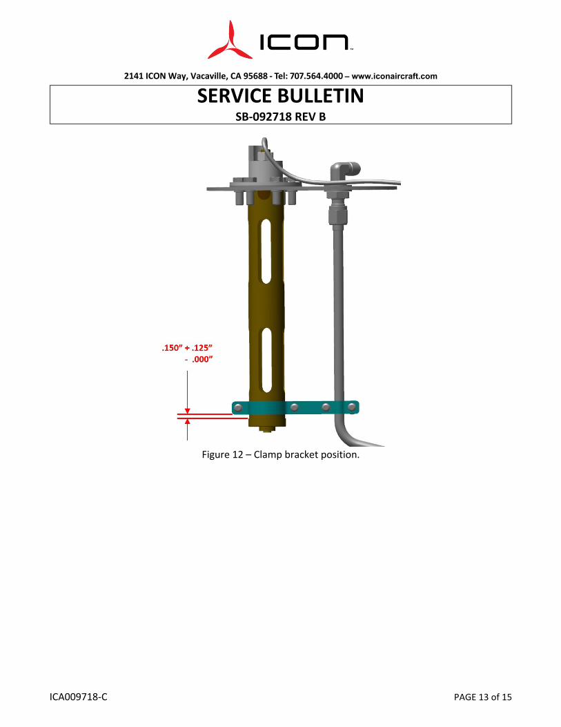
c. Position clamp bracket on fuel level sensor as shown in Figure 12. d. Install two washers, nut, and Torx screw on clamp bracket. While maintaining this position,
torque Torx screws on clamp bracket to 7-10 in-lbs. 2. Install fuel level sensor assembly into fuel tank, Figure 8 & 13:
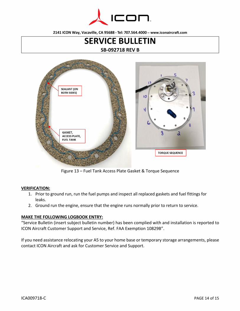
a. Clean fuel access plate with ISOPROPYL ALCOHOL. b. Apply SEALANT as one continuous bead approximately .030” - .060” thick to both sides of
the GASKET, ACCESS PLATE. i. SEALANT to be applied as straight lines between bolt holes and half crescents to
the interior around the bolt holes. ii. Allow SEALANT to sit for 5 minutes after being applied to GASKET, ACCESS PLATE
2141 ICON Way, Vacaville, CA 95688 ‐ Tel: 707.564.4000 – www.iconaircraft.com
SERVICE BULLETIN SB‐092718 REV B
ICA009718-C PAGE 11 of 15
surfaces before placing gasket onto fuel tank. c. Pull end of interior tubing from inside the fuel tank and secure to fuel level sensor
assembly using CABLE-TIE, NYLON 6-6, 18LB (see Figure 8). d. Lower the fuel level sensor assembly into the fuel tank ensuring that the SEALANT only
contacts the fuel tank access plate. e. Secure fuel tank access plate to fuel tank using THREADLOCKER, 12 nuts and washers
previously removed. i. Torque bolts 25-30 in-lb in a star shaped pattern as shown in Figure 13. ii. Repeat star shaped torque sequence 2-3 times to ensure that gasket is evenly
compressed and that all bolts are torqued to specification. 3. Secure the electrical connections to the fuel level sensor plate, Figure 7:
a. Use a 7/16 wrench to install bolt, washer, and ring terminals T9028 and T9026 ring onto the fuel level sensor plate.
b. Secure the fuel level sensor harness and the T9028 ground wire to the fuel tank cable tie mount using three CABLE-TIE, NYLON 6-6.
c. Connect the fuel level sensor connector to D9039P on the fuselage wire harness. 4. Connect exterior fuel supply line, Figure 6:
a. Remove any caps or plugs from the supply line fitting. b. Connect the exterior fuel supply line to the fitting on the fuel tank access plate. c. Apply THREADLOCKER and torque coarse fuel filter clamp bolt to 25-30 in-lb.
5. Install interior components in accordance with the latest release of the Aircraft Maintenance Manual, ICA000833.
a. Install seat backs b. Install baggage floor.
2141 ICON Way, Vacaville, CA 95688 ‐ Tel: 707.564.4000 – www.iconaircraft.com
SERVICE BULLETIN SB‐092718 REV B
ICA009718-C PAGE 12 of 15
Figure 11 – Fuel level sensor installation.
2141 ICON Way, Vacaville, CA 95688 ‐ Tel: 707.564.4000 – www.iconaircraft.com
SERVICE BULLETIN SB‐092718 REV B
ICA009718-C PAGE 13 of 15
Figure 12 – Clamp bracket position.
2141 ICON Way, Vacaville, CA 95688 ‐ Tel: 707.564.4000 – www.iconaircraft.com
SERVICE BULLETIN SB‐092718 REV B
ICA009718-C PAGE 14 of 15
Figure 13 – Fuel Tank Access Plate Gasket & Torque Sequence
VERIFICATION: 1. Prior to ground run, run the fuel pumps and inspect all replaced gaskets and fuel fittings for
leaks. 2. Ground run the engine, ensure that the engine runs normally prior to return to service.
MAKE THE FOLLOWING LOGBOOK ENTRY: “Service Bulletin (insert subject bulletin number) has been complied with and installation is reported to ICON Aircraft Customer Support and Service, Ref. FAA Exemption 10829B”. If you need assistance relocating your A5 to your home base or temporary storage arrangements, please contact ICON Aircraft and ask for Customer Service and Support.
2141 ICON Way, Vacaville, CA 95688 ‐ Tel: 707.564.4000 – www.iconaircraft.com
SERVICE BULLETIN SB‐092718 REV B
ICA009718-C PAGE 15 of 15
If you are no longer in possession of this aircraft, please forward this information to the present owner/operator and notify ICON Aircraft, Owners Center at:
ICON Aircraft 2141 ICON Way
Vacaville, CA 95688 (855) FLY-ICON
[email protected] Please include the aircraft registration number, serial number, your name, and if known the contact information of the new owner/operator.