hi-target dt-02 theodolite manual.pdf - ecomexico
TRANSCRIPT
1
Contents
1.INSTRUMENT FEATURES ........................................................... 4
2.QUICK GUIDE ........................................................................... 5
2.1 INSTRUMENT PACKING .................................................................... 5 2.2 NAME OF INSTRUMENT PARTS .......................................................... 6 2.3 UNPACK AND STORAGE ................................................................... 8 2.4 HANDLING, INFORMATION AND CHARGING OF THE BATTERY ................... 9 2.5 INSTALLATION OF THE INSTRUMENT ................................................. 12
3.INSTRUMENT OPERATION KEYS AND DISPLAY INSTRUCTIONS 13
3.1 KEYBOARD SYMBOLS AND FUNCTIONS ............................................. 13 3.2 LCD ......................................................................................... 15
4.PARAMETER SETTINGS ........................................................... 17
5.PREPARING FOR MEASUREMENT ........................................... 19
5.1 INSTRUMENT PLACEMENT, CENTERING AND LEVELING ......................... 19 5.1.1 Plumb bob on leveling ..................................................... 19 5.1.2 Use the plummet for centering .................................... 22
5.2 TELESCOPE EYEPIECE ADJUSTMENT AND TARGET SIGHTING ................... 23
2
5.3 SWITCH ON AND OFF ................................................................... 25
6.BASIC MEASUREMENT ........................................................... 26
6.1 DISC / DISK LEFT RIGHT SWITCH ...................................................... 26 6.2. SET HORIZONTAL ANGLE TO ZERO .................................................. 27 6.3 ANGLE LOCK ............................................................................... 28 6.4 THE VERTICAL ANGLE MODE SWITCH................................................ 29 6.5 INTO THE SWITCHING STATE ........................................................... 30 6.6 LIGHTING OPEN CLOSE ................................................................. 31 6.7 SWITCH AT RIGHT ANGLES TO BEEP .................................................. 31 6.8 SWITCHING COMPENSATOR ........................................................... 32 6.9 OUTPUT ANGLE DATA ................................................................... 33
7.ANGLE MEASUREMENT .......................................................... 35
7.1 HORIZONTAL ANGLE MEASUREMENTS (RIGHT CORNER MODE) .............. 35 7.2 HORIZONTAL ANGLE MEASUREMENTS (LEFT CORNER MODE) ................ 36 7.3 VERTICAL ANGLE MEASUREMENT .................................................... 37
8.DATA RECORDING AND TRANSMISSION FUNCTION ................ 38
8.1 RECORD THE ANGLE DATA .............................................................. 38 8.2 DATA VIEW AND TRANSMISSION ..................................................... 38
9.LASER POINT FUNCTION (LASER THEODOLITE) ....................... 40
3
9.1 LASER POINT TO OPEN AND CLOSE ................................................... 40 9.2 LASER POINTING ......................................................................... 40
10.CHECKOUT AND CALIBRATION ............................................. 42
10.1 LEVEL TUBE .............................................................................. 42 10.2 CIRCULAR LEVEL ........................................................................ 43 10.3 TELESCOPE RETICLE .................................................................... 44 10.4 THE VERTICALITY OF COLLIMATION AXIS AND HORIZONTAL AXIS (2 C) . 46 10.5 VERTICAL COLLIMATION ERROR (I ANGLE) AND VERTICAL COLLIMATION
ZERO VALUE SETTING .......................................................................... 47 10.6 CHECKING AND CORRECTION OF VERTICAL DIAL COMPENSATOR ........... 49 10.7 PLUMMET ................................................................................ 52
11. SPECIFICATIONS(ELECTRONIC THEODOLITE) ........................... 55
12.SPECIFICATIONS (LASER ELECTRONIC THEODOLITE) .............. 57
13.ATTACHMENT ....................................................................... 59
4
1.Instrument features
Our products DT-02 series Electronic Theodolite and laser Electronic Theodolite, absolute encoder angle measurement, eliminating the vertical plate angle initialization process, easy to operate; Large-diameter objective lens system for easytargeting operation; Nice, reasonable structure and ergonomic design; Fully functional, suitable for a variety of applications theodolite angle measurement; collection of data can be done directly.
through the serial port output; simple button operation, only six function keys can achieve a variety of measurement functions; big screen, clear font; display backlight reticle illumination for dark environments operation; laser point instead ofoptical vertical quasi use is easier than the optical; convenient laser theodolite emitting laser (only for laser theodolite), as a visible line of sightapplications in construction.
5
2.Quick Guide
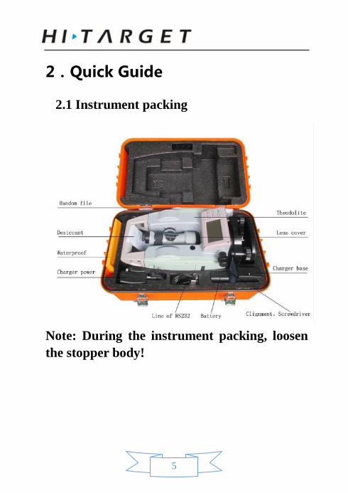
2.1 Instrument packing
Note: During the instrument packing, loosen the stopper body!
6
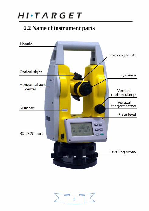
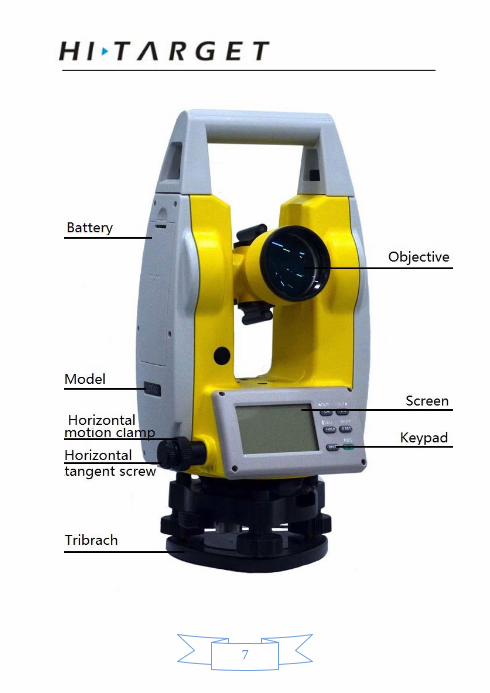
2.2 Name of instrument parts
7
8
Note: only in the back of the instrument model decorated with the letter L theodolite is laser theodolite.
2.3 Unpack and storage
Unpack Put down the instrument box lightly, so
that the lid upward to open the latch of the box, open the lid and remove the instrument.
Storage Telescope vertically down (or up), so tha
t the alidade base of packing marks are aligned, marked the instrument packing up supine into the box and gently tighten the vertical automatic knob cover box cover and lock the case.
9
2.4 Handling, information and charging of the battery
Battery handling
Remove the battery box, battery box at the top of the button is pressed outwards pull out at the top of the battery box.
When install the battery box the bottom of the battery compartment first projection is inserted into the groove on the instrument, press the top button of the battery compartment, so that it snaps into the instrument fixed homing.
Battery Information
Continuous work for 8 ~ 10 hours in full battery, Symbol in the lower left corner " " display battery consumption, the battery consumption is as follows: “ ” and “ ”: Fully charged and operable. “ ”: this information, means there is a small
amount of power, should be ready to replace the battery or charging before use.
10
“ ” lack of power, it will shut down about sustainable few minutes, replace the battery and charging right now.
Charging
Native 2100mAH NiMH high-energy rechargeable battery, please use the ZY-4Q500 dedicated charger.
For charging, connect 220v power supply first, the red light flash, the charger plug into thecharging connector socket, push the battery into the charging deck, red light means charging started, charging six hours or charging lights turn green means the end of charge, pull out the battery.
Warning: If the battery is placed improperly (such as positive and negative terminal), may cause an explosion, please follow the instructions for dealing with use batteries.
Note: when charging :
A one-time batteries;
11
Do not charge the battery before it have not been used or not spent much time on the repeated charge after fully charged, it will shorten the battery's life.
Charging in the temperature range of 0 ° ~ +45 °, and beyond this range may cause charging abnormality.
Do not use any charger or battery that had been damaged.
Storage Precautions:
The rechargeable batteries are rechargeable about 300-500 times, fully discharge the battery will shorten its life
For better access to the longest battery life, Please ensure that charged once a month.
Do not store the battery in high-temperature, high heat or humid places, not to short-circuit the battery, otherwise it will damage the battery.
Properly dispose of the battery according to local rules, better recovery, do not throw the
12
batteries in a fire.
2.5 Installation of the instrument
Disassembly :
If necessary, the instrument can be removedfrom the triangular base, first loosen the base locked twist fixing screws with a screwdriver, andthen lock twist of about 180 ° counter-clockwiserotation of the base to the instrument base separation.
Install
Align at instrument directional bulge mark and substrate directional groove , Three fixed foot on instrument corresponding to in hole in substrate, Install instrument on three substrate. lock twist of about 180 ° clockwise rotation of the base to the instrument lock with substrate, and then tighten the base locked twist fixing screws with a screwdriver.
13
3.Instrument operation keys and display instructions
3.1 Keyboard symbols and functions
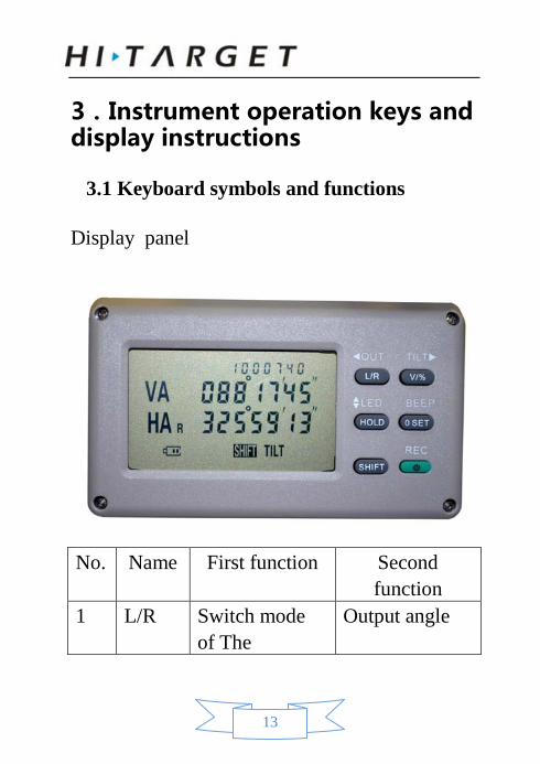
Display panel
No. Name First function Second function
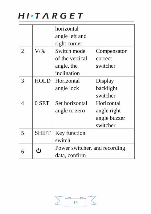
1 L/R Switch mode of The
Output angle
14
horizontal angle left and right corner
2 V/% Switch mode of the vertical angle, the inclination
Compensator correct switcher
3 HOLD Horizontal angle lock
Display backlight switcher
4 0 SET Set horizontal angle to zero
Horizontal angle right angle buzzer switcher
5 SHIFT Key function switch
6 Power switcher, and recording data, confirm
15
3.2 LCD
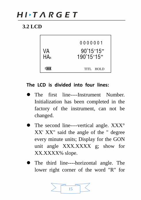
The LCD is divided into four lines:
The first line----Instrument Number. Initialization has been completed in the factory of the instrument, can not be changed.
The second line----vertical angle. XXX° XX' XX" said the angle of the " degree every minute units; Display for the GON unit angle XXX.XXXX g; show for XX.XXXX% slope.
The third line----horizontal angle. The lower right corner of the word "R" for
0 0 0 0 0 0 1
VA 90°15’15” HAR 190°15’15”
TITL HOLD
16
theright corner of the mode, increased clockwise rotation instrument angle; upper right corner of the word "left" means Left angle mode, counterclockwise rotation Instruments will cause angle increase.
The fourth line---- Electricity flag; Other “Direction”, “Point”, “Switch”, “Compensation”, ”lock” logo will display with the corresponding function on.
17
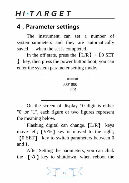
4.Parameter settings The instrument can set a number of
systemparameters and they are automatically saved when the set is completed.
In the off state, press the【L/R】+【0 SET】 key, then press the power button boot, you can enter the system parameter setting mode.
On the screen of display 10 digit is either
"0",or "1", each figure or two figures represent the meaning below.
Flashing digital can change.【L/R】 keys move left;【V/%】key is moved to the right; 【0 SET】 key to switch parameters between 0 and 1.
After Setting the parameters, you can click the 【 】key to shutdown, when reboot the
0000001
0001000 001
18
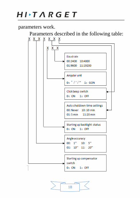
parameters work. Parameters described in the following table:
19
5.Preparing for measurement
5.1 Instrument placement, centering and leveling
Instrument mounted on a tripod, precise leveling and alignment to ensure the precision of the measurement results.
5.1.1 Plumb bob on leveling
1. Set up the tripod
Setup the tripod first: extend the extension legs to suitable lengths and tighten the screws on the mid sections. Make sure the legs are spaced at equal intervals and the head is approximately level. Set the tripod so that the head is positioned over the surveying point. Make sure the tripod -11-shoes are firmly fixed in the ground.
20
2. Mount the instrument on the tripod head
Mount the instrument on the tripod head. Supporting it with one hand, tighten the centering screw on the bottom of the unit to make sure it is secured to the tripod.
3. Centering and Leveling-Up
1. Position tripod legs so that the plummet is aimed to the ground mark point. Turn the focusing ring of the optical plummet to focus.
2. Turn three foot screws of the tribrach till the center of reticle exactly coincides with the surveying point in any position.
3. Move the tripod legs to centre the circular level. The instrument is now roughly leveled-up.
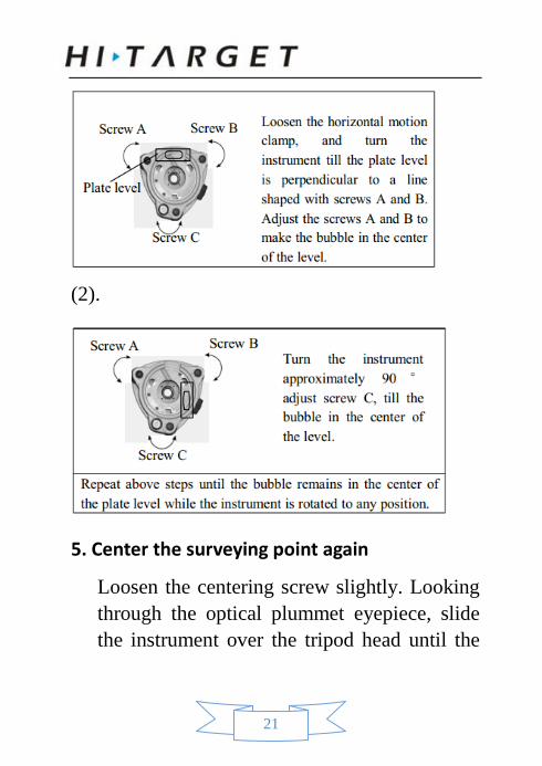
4. Center the bubble in the circular level.
(1).
21
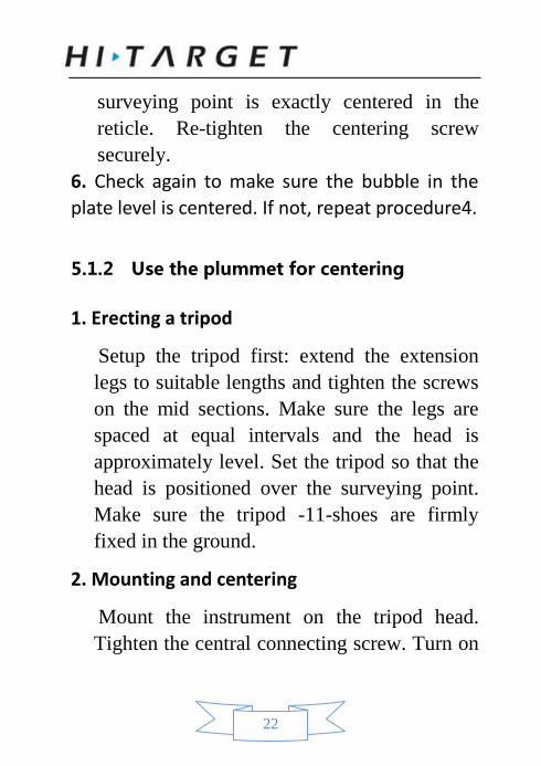
(2).
5. Center the surveying point again
Loosen the centering screw slightly. Looking through the optical plummet eyepiece, slide the instrument over the tripod head until the
22
surveying point is exactly centered in the reticle. Re-tighten the centering screw securely.
6. Check again to make sure the bubble in the plate level is centered. If not, repeat procedure4.
5.1.2 Use the plummet for centering
1. Erecting a tripod
Setup the tripod first: extend the extension legs to suitable lengths and tighten the screws on the mid sections. Make sure the legs are spaced at equal intervals and the head is approximately level. Set the tripod so that the head is positioned over the surveying point. Make sure the tripod -11-shoes are firmly fixed in the ground.
2. Mounting and centering
Mount the instrument on the tripod head. Tighten the central connecting screw. Turn on
23
the instrument, Pres 【 】 to open “Direction” light (Only for laser theodolite), Press 【 】again to open laser “Point”, we can see the red laser to the ground out from the base down. Through the laser we can adjust the position of the tripod point observation. So that the next point roughly aims at the station, make all three legs are fixed on the ground. Adjust the instrument three foot spiral to the point precisely to the measurement site.
3. Do centering and leveling work again refers to chapter 5.1.1 step 3 to step 5.
5.2 Telescope eyepiece adjustment and target sighting
Eyepiece adjustment
1. Remove the telescope mirror cover. 2. Pointing to the sky through the telescope,
adjusting the eyepiece knob, the most clear reticle crosshairs.
24
Object Sighting
1. Sight to the target with the crude sight. 2. Adjust the telescope focusing knob until the object can been seeing clearly. 3. Tighten the horizontal and vertical brake knob,
fine-tune the two micro knob to accurately sight the center of the crosshair to target, move eye up and down for slightly observe, if the relative shift between the two images of the target with the crosshairs, then fine-tune the telescope focusing knob until the two images clear and relatively stationary ended
Clockwise rotation of the focusing knob to closer to the target. Rotate counterclockwise for contrary.
If step (3) is not adjusted well, the parallax will distort the relationship of the target with the reticle center, then leading to the observation error.
Micro knob according to precise target for a final time, should keep the knob clockwise. If
25
the rotation is too far, we’d better return and re-sighting knob rotates clockwise.
Even if the eventuality vertical angle, we still recommend to sight the target as far as possible with the position of the center of the crosshairs.
5.3 Switch On and Off
Switch On
Operation: Click 【 】 button to boot, after boot it will display the surveying interface.
Switch Off
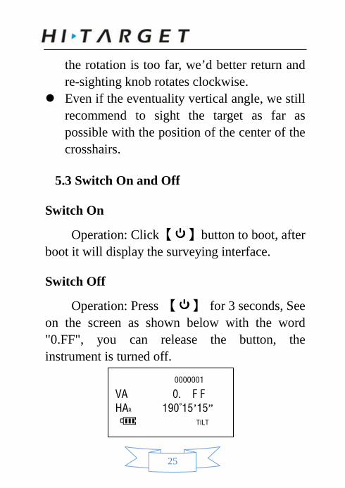
Operation: Press 【 】 for 3 seconds, See on the screen as shown below with the word "0.FF", you can release the button, the instrument is turned off.
0000001
VA 0. F F HAR 190°15’15”
TILT
26
6.Basic measurement
6.1 Disc / disk left right switch
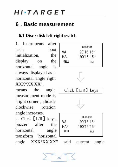
1. Instruments after each boot initialization, the display on the horizontal angle is always displayed as a horizontal angle right XXX°XX'XX", means the angle measurement mode is “right corner", alidade clockwise rotation angle increases. 2. Click【L/R】keys, buzzer after the horizontal angle transform "horizontal angle XXX°XX'XX" said current angle
0000001
VA 90°15’15” HAR 190°15’15”
TILT
Click【L/R】keys
0000001
VA 90°15’15” HA 190°15’15”
TILT
L
27
measurement mode "left corner" mode, means counterclockwise rotation cause angle increases. 3. Press【L/R】key to return to the right corner
measurement mode.
6.2. Set Horizontal angle to zero
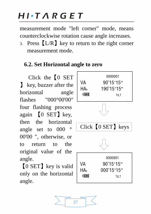
Click the【0 SET】 key, buzzer after the horizontal angle flashes "000°00'00" four flashing process again 【0 SET】key, then the horizontal angle set to 000 ° 00'00 ", otherwise, or to return to the original value of the angle. 【0 SET】key is valid only on the horizontal angle.
0000001
VA 90°15’15” HAR 000°15’15”
TILT
Click【0 SET】keys
0000001
VA 90°15’15” HAR 190°15’15”
TILT
28
6.3 Angle lock
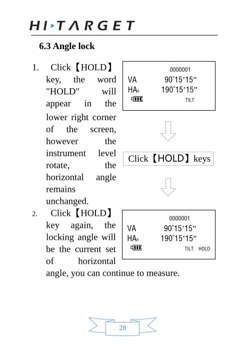
1. Click【HOLD】key, the word "HOLD" will appear in the lower right corner of the screen, however the instrument level rotate, the horizontal angle remains unchanged.
2. Click【HOLD】key again, the locking angle will be the current set of horizontal angle, you can continue to measure.
0000001
VA 90°15’15” HAR 190°15’15”
TILT
0000001
VA 90°15’15” HAR 190°15’15”
TILT HOLD
Click【HOLD】keys
29
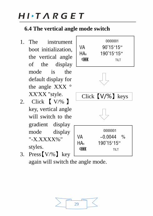
6.4 The vertical angle mode switch
1. The instrument boot initialization, the vertical angle of the display mode is the default display for the angle XXX ° XX'XX "style.
2. Click 【 V/% 】 key, vertical angle will switch to the gradient display mode display "-X.XXXX%" styles.
3. Press【V/%】 key again will switch the angle mode.
0000001
VA 90°15’15” HAR 190°15’15”
TILT
0000001
VA -0.0044 % HAR 190°15’15”
TILT
Click【V/%】keys
30
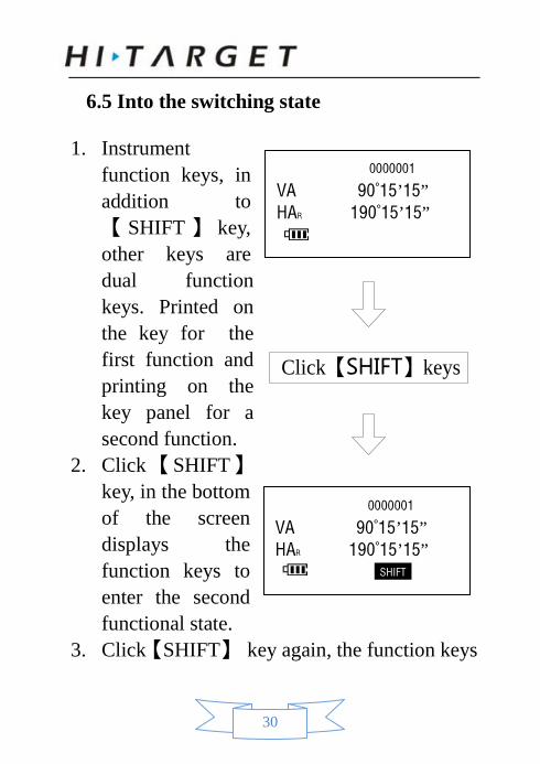
6.5 Into the switching state
1. Instrument function keys, in addition to 【 SHIFT 】 key, other keys are dual function keys. Printed on the key for the first function and printing on the key panel for a second function.
2. Click 【 SHIFT 】 key, in the bottom of the screen displays the function keys to enter the second functional state.
3. Click【SHIFT】 key again, the function keys
0000001
VA 90°15’15” HAR 190°15’15”
0000001
VA 90°15’15” HAR 190°15’15”
SHIFT
Click【SHIFT】keys
31
back to the first functional status.
6.6 Lighting Open Close
1. Click 【SHIFT】 key, the function keys to enter the second functional state.
2. Click 【HOLD】 key, then open the screen backlight and reticle illumination.
3. Click 【HOLD】 key, then turn off the screen backlight and reticle illumination.
4. Click 【SHIFT】key, the function keys back to the first functional status.
6.7 Switch at right angles to beep
1. Click【SHIFT】key, the function keys to enter the second functional state.
2. Click the【0 SET】key, then open the right angle buzzer, there will beep when the instrument horizontal angle Go around 90.180 270.0 degrees, allows you to easily find the desired location.
32
3. And then click the【0 SET】key, then turn off the horizontal angle right angle buzzer.
4. Click 【SHIFT】 key again, the function keys back to the first functional status.
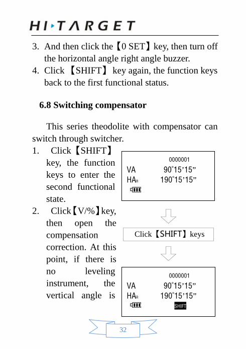
6.8 Switching compensator
This series theodolite with compensator can switch through switcher. 1. Click【SHIFT】
key, the function keys to enter the second functional state.
2. Click【V/%】key, then open the compensation correction. At this point, if there is no leveling instrument, the vertical angle is
0000001
VA 90°15’15” HAR 190°15’15”
0000001
VA 90°15’15” HAR 190°15’15”
SHIFT
Click【SHIFT】keys
33
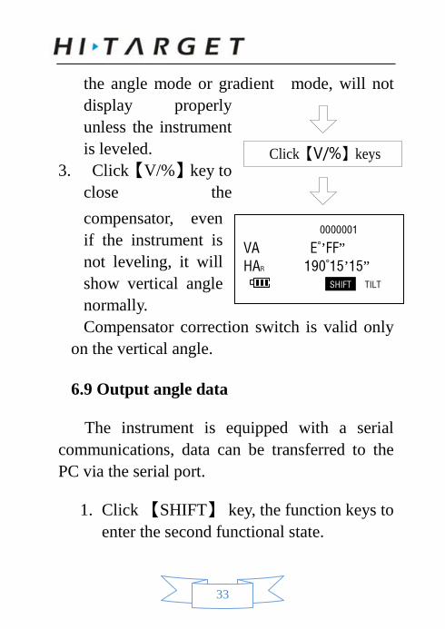
the angle mode or gradient mode, will not display properly unless the instrument is leveled.
3. Click【V/%】key to close the compensator, even if the instrument is not leveling, it will show vertical angle normally. Compensator correction switch is valid only
on the vertical angle.
6.9 Output angle data
The instrument is equipped with a serial communications, data can be transferred to the PC via the serial port.
1. Click 【SHIFT】 key, the function keys to enter the second functional state.
0000001
VA E°’FF” HAR 190°15’15”
SHIFT TILT
Click【V/%】keys
34
2. Connected to the instrument via the serial port to USB port cable with PC.
3. Open a can receive serial data software. 4. Set with the same instrument baud rate, 8
data bits, 1 stop bit, no parity. 5. Each time you press【L/R】key instrument
angle data transmission to the PC. 6. Outgoing data format: VXXX.XXXX + enter + newline VXXX.XXXX + enter + line feed
Outgoing data such as "V208.2323 \ r \ nH123.1212 \ r \ n",
Then it indicates that the current The vertical angle of: 208°23’23” Horizontal angle: 123°12’12”
35
7.Angle measurement
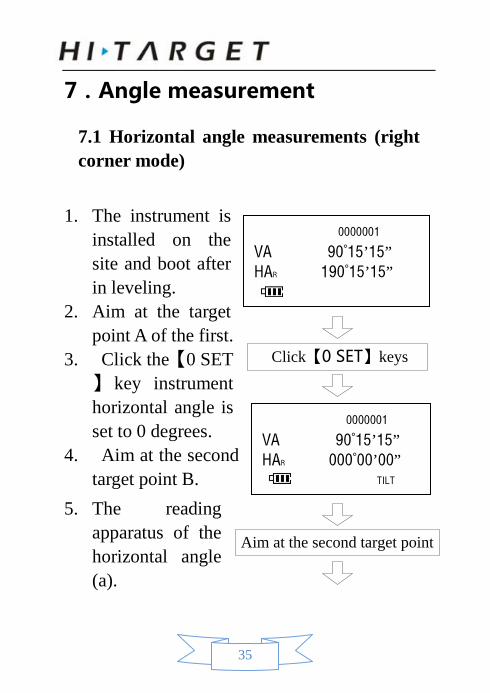
7.1 Horizontal angle measurements (right corner mode)
1. The instrument is installed on the site and boot after in leveling.
2. Aim at the target point A of the first.
3. Click the【0 SET】 key instrument horizontal angle is set to 0 degrees.
4. Aim at the second target point B.
5. The reading apparatus of the horizontal angle (a).
0000001
VA 90°15’15” HAR 190°15’15”
0000001
VA 90°15’15” HAR 000°00’00”
TILT
Aim at the second target point
Click【0 SET】keys
36
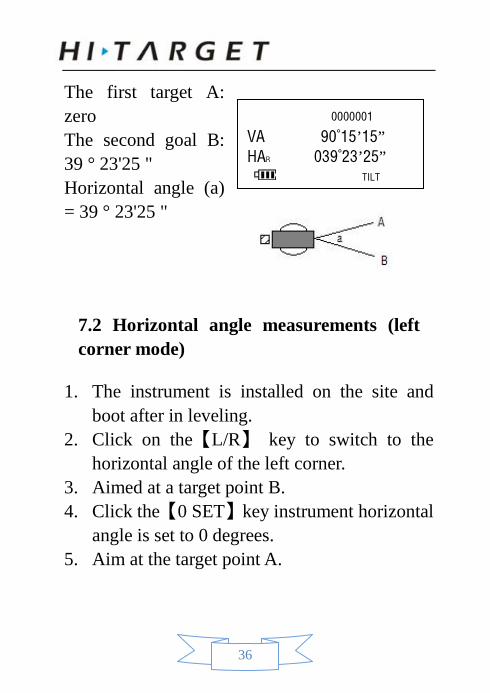
The first target A: zero The second goal B: 39 ° 23'25 " Horizontal angle (a) = 39 ° 23'25 "
7.2 Horizontal angle measurements (left corner mode)
1. The instrument is installed on the site and boot after in leveling.
2. Click on the【L/R】 key to switch to the horizontal angle of the left corner.
3. Aimed at a target point B. 4. Click the【0 SET】key instrument horizontal
angle is set to 0 degrees. 5. Aim at the target point A.
0000001
VA 90°15’15” HAR 039°23’25”
TILT
37
6. The reading apparatus of the horizontal angle (a).
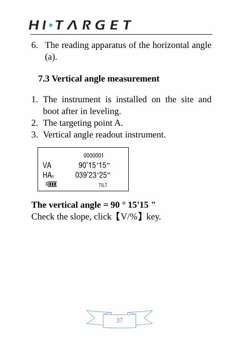
7.3 Vertical angle measurement
1. The instrument is installed on the site and boot after in leveling.
2. The targeting point A. 3. Vertical angle readout instrument.
The vertical angle = 90 ° 15'15 " Check the slope, click【V/%】key.
0000001
VA 90°15’15” HAR 039°23’25”
TILT
38
8.Data recording and transmission function
8.1 Record the angle data
1. State angle measurement, click【SHIFT】 key. 2. Each measurement is completed, you can
click【 】key recording angle data, including horizontal and vertical angles, can record up to 10 data.
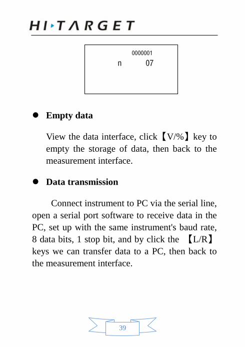
8.2 Data View and transmission
View
Holding【L/R】key and then press the【】key after turning instrument on, the interface displays the current record number of angle data, the following figure shows there are 7 data.
39
Empty data
View the data interface, click【V/%】key to empty the storage of data, then back to the measurement interface.
Data transmission
Connect instrument to PC via the serial line, open a serial port software to receive data in the PC, set up with the same instrument's baud rate, 8 data bits, 1 stop bit, and by click the 【L/R】keys we can transfer data to a PC, then back to the measurement interface.
0000001
n 07
40
9.Laser point function (laser theodolite)
The laser theodolite had added the laser system to telescope system, laser spot coincides with the telescope crosshairs visible in the telescope, convenient application in a variety of engineering construction.
9.1 Laser point to open and close
Boot, first press the【 】key, the screen last row shows the pointing, for now the pointing light is open. A second press【 】key to open the next point, the third press【 】key to open pointing light and next-to-point light at the same time, fourth press 【 】key will lead both of them to close, and so on.
9.2 Laser pointing
Rotate the telescope focusing hand wheel to
41
see the target, when the pointing function is on, the center of the crosshairs is the center of the laser spot, the laser spot is smallest and brightest. When the light is dim, first aim the target, after lit laser, or we can’t see the goal. ! Pay attention to safety. Note: The laser can injury human eyes! Never watch a laser light source with eyes!
42
10.Checkout and calibration
The instrument is under strict test and calibration, the quality is accord with the standard demand. But after a long-distance transportation and environment change, the small change of instrument parameter is inevitable. Therefore, the new purchased instruments should be checked and calibrated before surveying to ensure the precision.
10.1 Level tube
Checkout
Refer to the chapter "5.1 Centering and Leveling-Up".
Calibration
1. In the calibration, if the leveling bulb diverge from the center, use the foot spiral which parallels the leveling tube to adjust to make
43
the bubble move half of the distance to the center. For the remaining, use the calibration needle to turn the level calibration screw (in the right of the water-level) to adjust the bubble to the center.
2. Turn the instrument for 180°, check that whether the bubble is in the center. If the bubble is not centered, repeat step (1) until the bubble to the center.
3. Turn the instrument for 90°, use the third foot screw to adjust the bubble to the center.
•Repeat the steps of checkout and calibration until the bubble in the center in every directions .
10.2 Circular level
Checkout
After the level tube is calibrated correct, if the circular level bubble also in the center ,so there is no need to calibrate.
44
Calibration If the bubbles is not in the center, use the correction needle or six angle wrench to adjust the correction screw which under the bubble to make the buble to the center. For calibration ,you shall first loosen the calibration screw (1 or 2) which opposite to the direction of the bubble offset, then tighten the other correction screw in the offset direction to make the bubble in the center. When the bubble is in center, make sure the pressure of the three calibration screws are consistent.
10.3 Telescope reticle
Checkout
1. After leveling the instrument find a target A with the telescope, make the center of the crosshair focused on target A and fixed horizontal and vertical brake handwheel.
2. Rotate telescope vertical micrometer handwheel, move A point to the edge of the
45
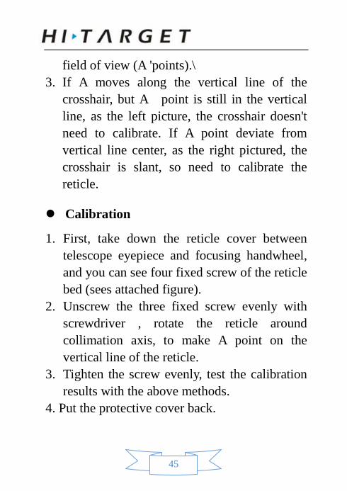
field of view (A 'points).\ 3. If A moves along the vertical line of the
crosshair, but A point is still in the vertical line, as the left picture, the crosshair doesn't need to calibrate. If A point deviate from vertical line center, as the right pictured, the crosshair is slant, so need to calibrate the reticle.
Calibration
1. First, take down the reticle cover between telescope eyepiece and focusing handwheel, and you can see four fixed screw of the reticle bed (sees attached figure).
2. Unscrew the three fixed screw evenly with screwdriver , rotate the reticle around collimation axis, to make A point on the vertical line of the reticle.
3. Tighten the screw evenly, test the calibration results with the above methods.
4. Put the protective cover back.
46
10.4 The verticality of collimation axis and horizontal axis (2 C)
Checkout
1. Set a target A in about 100m away, and make sure the vertical angle of the target is within ±3°.Precisely level the instrument and switch on it.
2. Make the telescope focused on target A in face left, and read the horizontal angle.
For example: horizontal Angle L = 10°13 '10" 3. Loosen the vertical and horizontal brake
handwheel, turn the telescope, rotate the alidade to face right and focus on the same target A. Before aiming please tighten the horizontal and vertical brake handwheel and read the horizontal angle. For example: level Angle R = 190°13 '40"
4. 2C = L - (R ±180 °) = -30 "≥±20 ", need to calibrate.
47
Calibration
1. Use the horizontal micrometer handwheel to adjust the horizontal angle to the right reading which has eliminated the C. R + C = 190°13 '40 "-15 "= 190°13' 25". 2. Take down the reticle bed cover between the telescope eyepiece and focusing handwheel, adjust the calibration screw of the crosshair on the left and right. First, loosen the screw on one side, and screw up the screw on the other side, move the reticle and focus on target A. 3. Repeat the test steps, calibrate it to | 2 C | < 10. 4. Tighten the calibration screws, put the protective cover back. Notice: Check the photoelectric coaxiality after calibrating.
10.5 Vertical collimation error (I Angle) and vertical collimation zero value setting
After finishing §17.3 and §17.5 calibration
48
project, and then do this checking.
Checkout
1. Boot after settling and leveling the instrument, focus the telescope on a clear goals A, get the face left reading of vertical Angle L.
2. Turn the telescope to aim A and get the reading R for face right.
3. If the vertical zenith angle is 0°, then i = (L + R-360°) / 2, if the vertical Angle level is 0 . Then i = (L + R-180°) / 2 or (L + R-540 °) / 2.
4. If | i |≥10", may be you need reset the zero value of vertical index.
5. Operation refers to chapter 9.6.1 "index error calibration"
Note: Repeat the checkout steps to retest the index error again (i Angle). If the index error still can not accordance with requirements , it should check the three steps of calibration index zero setting (in the course of zero setting ,the vertical angle showed is not compensated and corrected,
49
it is just for reference) to see whether it is incorrect, whether the focusing of target is correct, reset according to the requirements. 6. If it still can’t accordant with the requirements after repeated operation, it should be sent to the factory for checking.
10.6 Checking and correction of vertical dial compensator
Checkout
1. Set up and level the instrument, make the direction of the telescope consistent with the line between the center of the instrument and any of the foot screw.
2. With a telescope aimed at a vertical angle of the collimator reticle or distant targets within ± 10 °, the vertical angle readings V1.
3. Rotate the vertical micro handwheel to make vertical angle readings larger or smaller 3 '.
4. Adjust the other foot spiral, the instrument re-sighting the target vertical angle readings
50
V2. 5. Calculated: vertical disk readings change
value dV = V2-V1. 6. If the absolute value of the dV is smaller than
the 3 "do not need to be corrected, otherwise it need compensation correction.
Calibration
Make the two compensation of the positive lens and the inverted mirror position readings’ sum less than 50, use the scale division plate, screw triangle base in the following order of operation, complete the compensator settings. Set up and level the instrument, make the direction of the telescope consistent with the line between the center of the instrument and any of the foot screw. 【L/R】 + 【HOLD】 key is pressed at the same time, and then press the power button to boot into correction compensator mode. The second line shows the vertical angle of the instrument screen, the third line of the first number 1
51
represents a first step, the followed one is compensator reading. Backward 3 ' use the foot screw of the vertical axis, vertical micro knob sighting crosshairs, waiting compensator indication stable, press the 【 】 key for the second time. Upward 3 ' use the foot screw of the vertical axis, vertical micro knob sighting crosshairs, waiting compensator indication stable, press the 【 】 key for the second time. Make the vertical axis plumb inverted mirror sighting crosshairs, backward 3 ' use the foot screw of the vertical axis, vertical micro knob sighting crosshairs, waiting compensator indication stable, press the 【 】 key for the third time. Upward 3 ' use the foot screw of the vertical axis, vertical micro knob sighting crosshairs, waiting compensator indication stable, press the 【 】 key for the fourth time. Compensation value is displayed on the screen, press the 【 】 key for the fifth time.
52
Compensator automatically corrected through the steps above, and we can exit the compensator correction operation at any time through the above process 【SHIFT】 key.
10.7 Plummet
Checkout
1. Set up the instrument to the tripod, draw a cross on a white paper and put it on the ground below the instrument.
2. Adjust the focal length of the optical plummet (for the optical plummet) or switch on laser plummet, move the white paper to make the cross in the center in the field of view (or laser flare).
3. Turn the feet screw, make the center mark of the plummet coincide with the cross center.
4. Rotate alidade, every turn of 90°, observe the contact ratio of the optical plummet and cross center.
5. When rotate the alidade, the center of the
53
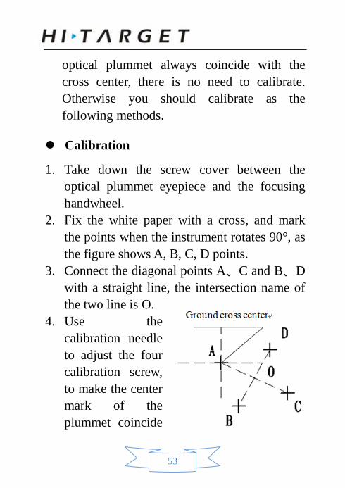
optical plummet always coincide with the cross center, there is no need to calibrate. Otherwise you should calibrate as the following methods.
Calibration
1. Take down the screw cover between the optical plummet eyepiece and the focusing handwheel.
2. Fix the white paper with a cross, and mark the points when the instrument rotates 90°, as the figure shows A, B, C, D points.
3. Connect the diagonal points A、C and B、D with a straight line, the intersection name of the two line is O.
4. Use the calibration needle to adjust the four calibration screw, to make the center mark of the plummet coincide
54
with point O. 5. Repeat step 4, check and calibrate until it
meet the requirements. 6. With the laser plummet, unbolt the laser
cover, using 1 # hex wrench to adjust the three screws, fasten one side and loosen the other side, and adjust the laser flare to point O.
7. Put the cover back in place.
55
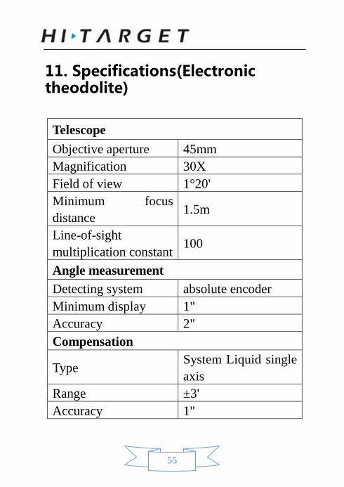
11. Specifications(Electronic theodolite)
Telescope Objective aperture 45mm Magnification 30X Field of view 1°20' Minimum focus distance 1.5m
Line-of-sight multiplication constant 100
Angle measurement Detecting system absolute encoder Minimum display 1" Accuracy 2" Compensation
Type System Liquid single axis
Range ±3' Accuracy 1"
56
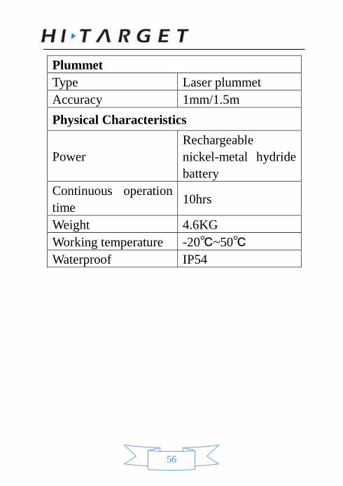
Plummet Type Laser plummet Accuracy 1mm/1.5m Physical Characteristics
Power Rechargeable nickel-metal hydride battery
Continuous operation time 10hrs
Weight 4.6KG Working temperature -20℃~50℃ Waterproof IP54
57
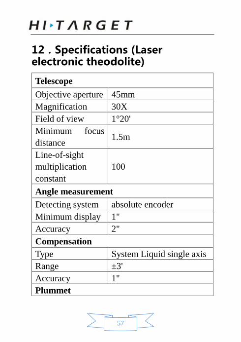
12.Specifications (Laser electronic theodolite)
Telescope Objective aperture 45mm Magnification 30X Field of view 1°20' Minimum focus distance 1.5m
Line-of-sight multiplication constant
100
Angle measurement Detecting system absolute encoder Minimum display 1" Accuracy 2" Compensation Type System Liquid single axis Range ±3' Accuracy 1" Plummet
58
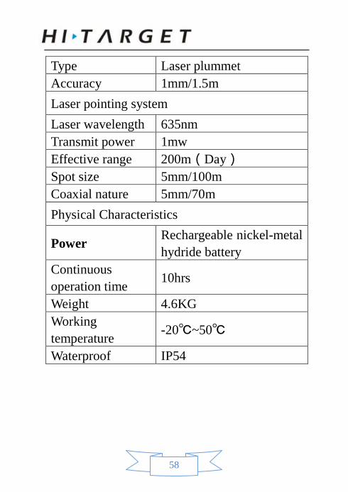
Type Laser plummet Accuracy 1mm/1.5m Laser pointing system Laser wavelength 635nm Transmit power 1mw Effective range 200m(Day) Spot size 5mm/100m Coaxial nature 5mm/70m Physical Characteristics
Power Rechargeable nickel-metal hydride battery
Continuous operation time 10hrs
Weight 4.6KG Working temperature -20℃~50℃
Waterproof IP54
59
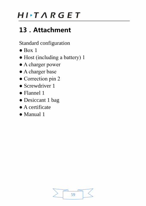
13.Attachment
Standard configuration ● Box 1 ● Host (including a battery) 1 ● A charger power ● A charger base ● Correction pin 2 ● Screwdriver 1 ● Flannel 1 ● Desiccant 1 bag ● A certificate ● Manual 1