dt-v24g2 dt-v21g2 dt-v17g2 dt-v17g25
TRANSCRIPT
MULTI FORMAT LCD MONITOR
INSTRUCTIONS
DT-V24G2DT-V21G2DT-V17G2DT-V17G25
®
B5A-1245-00
The illustration of the monitor is of DT-V21G2.
This is the English instruction manual. Instruction manuals in other languages (German, French, Italian, Spanish, Russian) are included on the supplied CD-ROM as PDF files (for Europe only).
For Customer Use:Enter below the Model No. and Serial No. which is located on the body. Retain this information for future reference.
Model No.Serial No.
: :
Please read the following before getting started:Thank you for purchasing this product.Before operating this unit, please read the instructions carefully to ensure the best possible performance.
DT-V24G2_EN.indb 1 2016/07/27 16:36:59
22
Safety Precautions (English)Before use, read “Safety Precautions” carefully, and then operate the product correctly.
FCC NOTICECAUTION: Changes or modifications not approved by JVC could void the user’s authority to operate the equipment.NOTE: This equipment has been tested and found to comply with the limits for a Class A digital device, pursuant to Part 15 of the FCC Rules. These limits are designed to provide reasonable protection against harmful interference when the equipment is operated in a commercial environment. This equipment generates, uses, and can radiate radio frequency energy and, if not installed and used in accordance with the instruction manual, may cause harmful interference to radio communications. Operation of this equipment in a residential area is likely to cause harmful interference in which case the user will be required to correct the interference at his own expense.
CAN ICES-3A / NMB-3 A
Warning: This is a class A product. In a domestic environment this product may cause radio interference in which case the user may be required to take adequate measures.
Use only the power source specified on the unit.• AC power: 120 V/220 V – 240 V, 50 Hz/60 Hz• DC power: 12 V – 17 V (DT-V21G2/DT-V17G2 only)
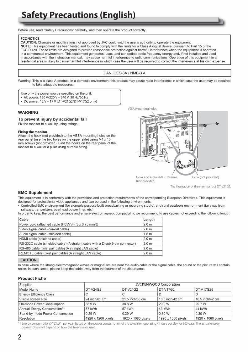
WARNINGTo prevent injury by accidental fallFix the monitor to a wall by using strings.
Fixing the monitorAttach the hook (not provided) to the VESA mounting holes on the rear panel (use the two holes on the upper side) using M4 x 10 mm screws (not provided). Bind the hooks on the rear panel of the monitor to a wall or a pillar using durable string.
Hook (not provided)
VESA mounting holes
The illustration of the monitor is of DT-V21G2.
Hook and screw (M4 x 10 mm) (not provided)
EMC SupplementThis equipment is in conformity with the provisions and protection requirements of the corresponding European Directives. This equipment is designed for professional video appliances and can be used in the following environments:• Controlled EMC environment (for example purpose built broadcasting or recording studio), and rural outdoors environment (far away from
railways, transmitters, overhead power lines, etc.)In order to keep the best performance and ensure electromagnetic compatibility, we recommend to use cables not exceeding the following length:
Cable LengthPower cord (attached cable (H05VV-F 3 x 0.75 mm2)) 2.0 mVideo signal cable (coaxial cable) 2.0 mAudio signal cable (shielded cable) 1.5 mHDMI cable (shielded cable) 2.0 mRS-232C cable (shielded cable) (A straight cable with a D-sub 9-pin connector) 2.0 mRS-485 cable (twist pair cable) (A straight LAN cable) 2.0 mREMOTE cable (twist pair cable) (A straight LAN cable) 2.0 m
CAUTIONIn case where the strong electromagnetic waves or magnetism are near the audio cable or the signal cable, the sound or the picture will contain noise. In such cases, please keep the cable away from the sources of the disturbance.
Product FicheSupplierModel Name DT-V24G2 DT-V21G2 DT-V17G2 DT-V17G25Energy Efficiency Class C C D DVisible screen size 24 inch/61 cm 21.5 inch/55 cm 16.5 inch/42 cm 16.5 inch/42 cmOn-mode Power Consumption 38.9 W 38.8 W 29.0 W 29.7 WAnnual Energy Consumption*1 57 kWh 57 kWh 43 kWh 44 kWhStand-by mode Power Consumption 0.29 W 0.29 W 0.30 W 0.30 WResolution 1920 x 1200 pixels 1920 x 1080 pixels 1920 x 1080 pixels 1920 x 1080 pixels
*1 Energy consumption XYZ kWh per year, based on the power consumption of the television operating 4 hours per day for 365 days. The actual energy consumption will depend on how the television is used.
DT-V24G2_EN.indb 2 2016/07/27 16:37:02
33
Caution for use of the product for many hoursIn the case that you use the monitor for many hours, we recommend that you set “No Sync Action” in “Sync Function” to “Power Save” in Main Menu (+ page 15). This will reduce power consumption and relieve strain on the monitor. To reduce damage to the LCD panel, using the LCD Saver function is recommended. (+ page 16)
Caution for use of the product in the high temperatureDo not use the product in places of high temperature; otherwise, parts of this product or the LCD panel may be damaged. This product is equipped with a temperature sensor to give warning if the temperature becomes too high. If the temperature exceeds the range of normal use, “Temp. Over” is displayed, and the power is turned off automatically if the temperature becomes any higher. In this case, move the product to a place of low temperature to let it cool down.
MaintenanceUnplug this product from the wall outlet before cleaning.
LCD panelTo avoid irreparable change in appearance of the screen such as uneven color, discoloration, scratches, be careful about the following:l Do not paste or stick anything using any glues or adhesive
tapes.l Do not write anything on the screen.l Do not strike the screen with a hard object.l Avoid condensation on the screen.l Do not wipe the screen with any liquid such as water. In
addition, wiping the screen with water-diluted neutral detergent or solvent such as alcohol, thinner, or benzine may affect the anti-reflection treatment of the screen.
l Do not wipe the screen forcefully.
Wipe stains off the LCD panel with a soft cloth. If the screen gets heavily stained, wipe it with a soft cloth soaked in water-diluted neutral detergent and wrung well, then wipe with a soft dry cloth.
CabinetTo avoid the deterioration or damages of the cabinet such as its paint’s peeling away, be careful about the following:l Do not wipe the cabinet using solvent such as alcohol, thinner,
or benzine.l Do not expose the cabinet to any volatile substance such as
insecticides.l Do not allow any rubber or plastic in contact for a long time.l Do not wipe the cabinet forcefully.
Wipe stains off the cabinet with a soft cloth. If the cabinet gets heavily stained, wipe it with a soft cloth soaked in water-diluted neutral detergent and wrung well, then wipe with a soft dry cloth.
Ventilation openingsUse a vacuum cleaner to get rid of the dust around the intakes (all the openings). If a vacuum cleaner is not available, use a cloth and wipe it off. Leaving the dust around the intakes may prevent proper temperature control and cause damage to the product.
The LCD panel and backlight have life expectancy. Due to the basic characteristics of the LCD panel, an afterimage or uneven display may occur. It is recommended that you change images occasionally, activate the power saving function, or often turn off the power to reduce the load on the LCD panel. Continuous operations of the LCD panel may accelerate the deterioration.
Operating Precautions
Table of Contents
Safety Precautions (English) . . . . . . . . . . 2Operating Precautions . . . . . . . . . . . . . . . 3
Caution for use of the product for many hours 3Caution for use of the product in the high temperature 3Maintenance 3
Installation . . . . . . . . . . . . . . . . . . . . . . . . . . . 4Index of Parts and Functions . . . . . . . . . 5
Rear panel 5Front panel 6
Showing Input Signals . . . . . . . . . . . . . . . 8Audio Channel Selection 8On the Information Display 8On the Status Display 8
Menu Configuration . . . . . . . . . . . . . . . . . . 9First Time Installation 9The operation procedure 9Menu Transition Diagram 10Main Menu 11Set-Up Menu 15
External Control . . . . . . . . . . . . . . . . . . . . .20About the external control 20Using the MAKE/TRIGGER system 20Using the serial communication 21
Troubleshooting . . . . . . . . . . . . . . . . . . . .23Self-check program 24
Specifications . . . . . . . . . . . . . . . . . . . . . . .25General 25LCD panel 25Input/output terminals 25Dimensions 26Available signals 27
Sicherheitsmaßregeln (Deutsch) . . . . .28Précautions de sécurité (Français). . . .29Precauzioni di sicurezza (Italiano) . . . .30Precauciones de seguridad (Español) . . .31Меры предосторожности (Русский) . . .32Указатель частей и функций . . . . . . .33
DT-V24G2_EN.indb 3 2016/07/27 16:37:04
44
Installation
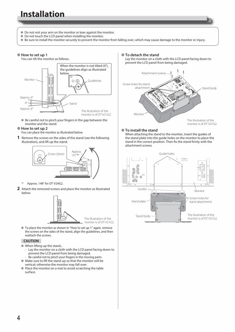
l How to set up 1 You can tilt the monitor as follows.
When the monitor is not tilted (0°), the guidelines align as illustrated below.
Guidelines
Stand
Monitor
Approx. 6°
0°
Approx. 6°The illustration of the monitor is of DT-V21G2.
l Be careful not to pinch your fingers in the gap between the monitor and the stand.
l How to set up 2 You can place the monitor as illustrated below.
1 Remove the screws on the sides of the stand (see the following illustration), and lift up the stand.
Screw (silver)Approx. 141° *1
*1 Approx. 148° for DT-V24G2.
2 Attach the removed screws and place the monitor as illustrated below.
The illustration of the monitor is of DT-V21G2.
l To place the monitor as shown in “How to set up 1” again, remove the screws on the sides of the stand, align the guidelines, and then reattach the screws.
CAUTIONl When lifting up the stand...
- Lay the monitor on a cloth with the LCD panel facing down to prevent the LCD panel from being damaged.
- Be careful not to pinch your fingers in the moving parts.l Make sure to lift the stand up so that the monitor will be
vertical; otherwise the monitor may fall over.l Place the monitor on a mat to avoid scratching the table
surface.
l Do not rest your arm on the monitor or lean against the monitor.l Do not touch the LCD panel when installing the monitor.l Be sure to install the monitor securely to prevent the monitor from falling over, which may cause damage to the monitor or injury.
l To detach the stand Lay the monitor on a cloth with the LCD panel facing down to
prevent the LCD panel from being damaged.
Attachment screws
Screw holes for stand attachment Stand body
Monitor
The illustration of the monitor is of DT-V21G2.
l To install the stand When attaching the stand to the monitor, insert the guides of
the stand plate into the guide holes on the monitor to place the stand in the correct position. Then fix the stand firmly with the attachment screws.
Monitor
Screw holes for stand attachment
Guides
Guide holes
Stand plate
Stand body The illustration of the monitor is of DT-V21G2.
DT-V24G2_EN.indb 4 2016/07/27 16:37:06
55
Index of Parts and Functions
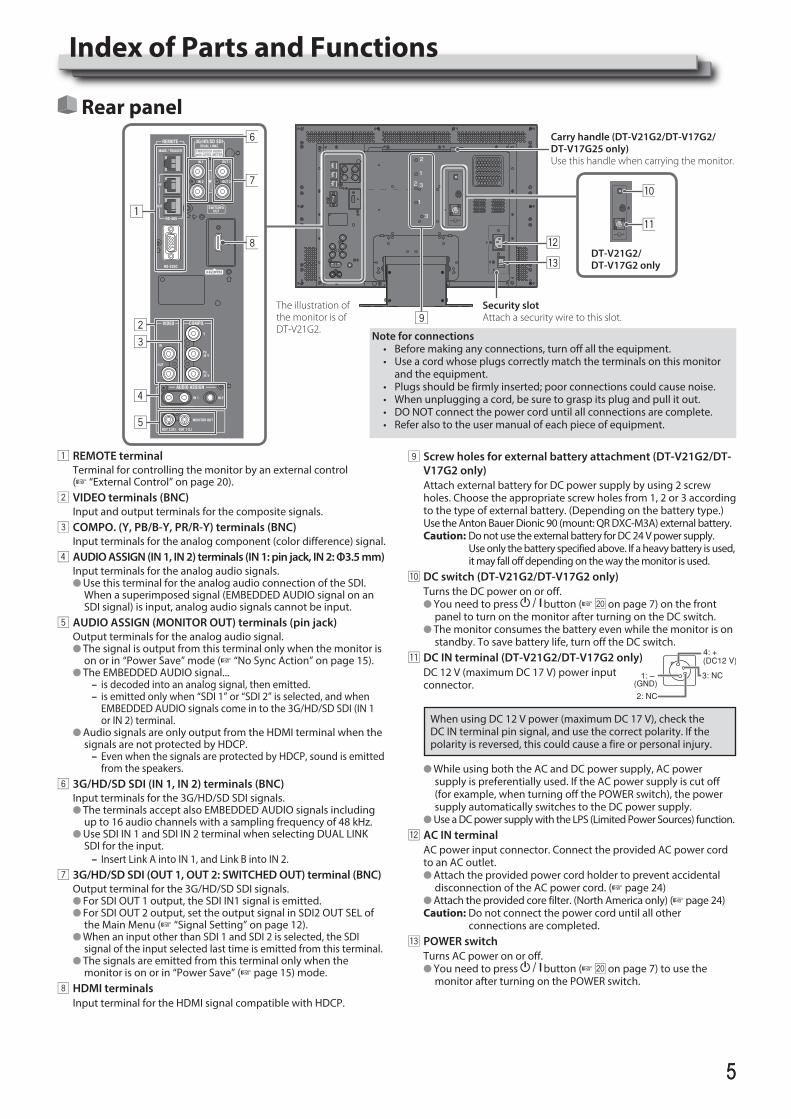
1 REMOTE terminalTerminal for controlling the monitor by an external control (+ “External Control” on page 20).
2 VIDEO terminals (BNC)Input and output terminals for the composite signals.
3 COMPO. (Y, PB/B-Y, PR/R-Y) terminals (BNC)Input terminals for the analog component (color difference) signal.
4 AUDIO ASSIGN (IN 1, IN 2) terminals (IN 1: pin jack, IN 2: Φ3.5 mm)Input terminals for the analog audio signals.l Use this terminal for the analog audio connection of the SDI.
When a superimposed signal (EMBEDDED AUDIO signal on an SDI signal) is input, analog audio signals cannot be input.
5 AUDIO ASSIGN (MONITOR OUT) terminals (pin jack)Output terminals for the analog audio signal.l The signal is output from this terminal only when the monitor is
on or in “Power Save” mode (+ “No Sync Action” on page 15).l The EMBEDDED AUDIO signal...
– is decoded into an analog signal, then emitted. – is emitted only when “SDI 1” or “SDI 2” is selected, and when EMBEDDED AUDIO signals come in to the 3G/HD/SD SDI (IN 1 or IN 2) terminal.
l Audio signals are only output from the HDMI terminal when the signals are not protected by HDCP.
– Even when the signals are protected by HDCP, sound is emitted from the speakers.
6 3G/HD/SD SDI (IN 1, IN 2) terminals (BNC)Input terminals for the 3G/HD/SD SDI signals.l The terminals accept also EMBEDDED AUDIO signals including
up to 16 audio channels with a sampling frequency of 48 kHz.l Use SDI IN 1 and SDI IN 2 terminal when selecting DUAL LINK
SDI for the input. – Insert Link A into IN 1, and Link B into IN 2.
7 3G/HD/SD SDI (OUT 1, OUT 2: SWITCHED OUT) terminal (BNC)Output terminal for the 3G/HD/SD SDI signals.l For SDI OUT 1 output, the SDI IN1 signal is emitted.l For SDI OUT 2 output, set the output signal in SDI2 OUT SEL of
the Main Menu (+ “Signal Setting” on page 12).l When an input other than SDI 1 and SDI 2 is selected, the SDI
signal of the input selected last time is emitted from this terminal.l The signals are emitted from this terminal only when the
monitor is on or in “Power Save” (+ page 15) mode.8 HDMI terminals
Input terminal for the HDMI signal compatible with HDCP.
Rear panel
9 Screw holes for external battery attachment (DT-V21G2/DT-V17G2 only)Attach external battery for DC power supply by using 2 screw holes. Choose the appropriate screw holes from 1, 2 or 3 according to the type of external battery. (Depending on the battery type.) Use the Anton Bauer Dionic 90 (mount: QR DXC-M3A) external battery.Caution: Do not use the external battery for DC 24 V power supply. Use only the battery specified above. If a heavy battery is used,
it may fall off depending on the way the monitor is used.p DC switch (DT-V21G2/DT-V17G2 only)
Turns the DC power on or off.l You need to press button (+ ; on page 7) on the front
panel to turn on the monitor after turning on the DC switch.l The monitor consumes the battery even while the monitor is on
standby. To save battery life, turn off the DC switch.q DC IN terminal (DT-V21G2/DT-V17G2 only)
DC 12 V (maximum DC 17 V) power input connector.
When using DC 12 V power (maximum DC 17 V), check the DC IN terminal pin signal, and use the correct polarity. If the polarity is reversed, this could cause a fire or personal injury.
l While using both the AC and DC power supply, AC power supply is preferentially used. If the AC power supply is cut off (for example, when turning off the POWER switch), the power supply automatically switches to the DC power supply.
l Use a DC power supply with the LPS (Limited Power Sources) function.w AC IN terminal
AC power input connector. Connect the provided AC power cord to an AC outlet.l Attach the provided power cord holder to prevent accidental
disconnection of the AC power cord. (+ page 24)l Attach the provided core filter. (North America only) (+ page 24)Caution: Do not connect the power cord until all other
connections are completed.e POWER switch
Turns AC power on or off.l You need to press button (+ ; on page 7) to use the
monitor after turning on the POWER switch.
Note for connections• Beforemakinganyconnections,turnoffalltheequipment.• Useacordwhoseplugscorrectlymatchtheterminalsonthismonitor
and the equipment.• Plugsshouldbefirmlyinserted;poorconnectionscouldcausenoise.• Whenunpluggingacord,besuretograspitsplugandpullitout.• DONOTconnectthepowercorduntilallconnectionsarecomplete.• Referalsototheusermanualofeachpieceofequipment.
Carry handle (DT-V21G2/DT-V17G2/ DT-V17G25 only)Use this handle when carrying the monitor.
DT-V21G2/ DT-V17G2 only
Security slotAttach a security wire to this slot.
The illustration of the monitor is of DT-V21G2.
DT-V24G2_EN.indb 5 2016/07/27 16:37:07
66
Index of Parts and Functions (cont.)
The illustration of the monitor is of DT-V21G2.
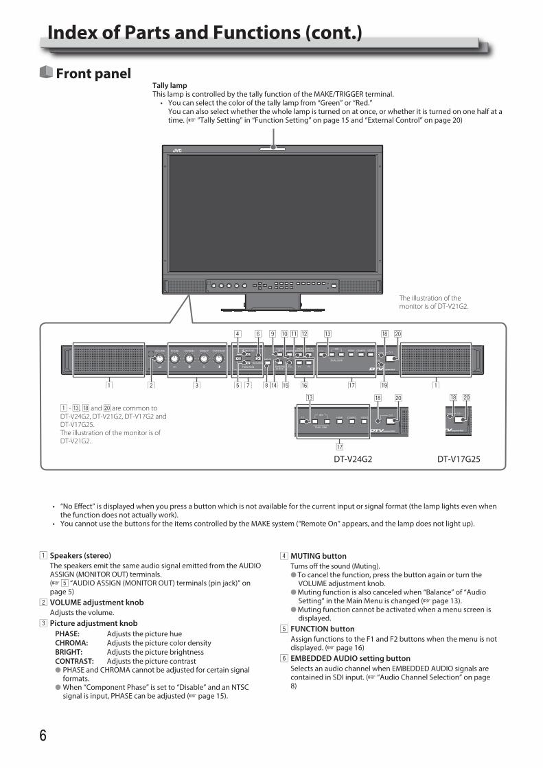
Front panelTally lampThis lamp is controlled by the tally function of the MAKE/TRIGGER terminal.• Youcanselectthecolorofthetallylampfrom“Green”or“Red.” You can also select whether the whole lamp is turned on at once, or whether it is turned on one half at a
time. (+ “Tally Setting” in “Function Setting” on page 15 and “External Control” on page 20)
• “NoEffect”isdisplayedwhenyoupressabuttonwhichisnotavailableforthecurrentinputorsignalformat(thelamplightsevenwhenthe function does not actually work).
• YoucannotusethebuttonsfortheitemscontrolledbytheMAKEsystem(“RemoteOn”appears,andthelampdoesnotlightup).
1 Speakers (stereo)The speakers emit the same audio signal emitted from the AUDIO ASSIGN (MONITOR OUT) terminals.(+ 5 “AUDIO ASSIGN (MONITOR OUT) terminals (pin jack)” on page 5)
2 VOLUME adjustment knobAdjusts the volume.
3 Picture adjustment knobPHASE: Adjusts the picture hueCHROMA: Adjusts the picture color densityBRIGHT: Adjusts the picture brightnessCONTRAST: Adjusts the picture contrastl PHASE and CHROMA cannot be adjusted for certain signal
formats.l When “Component Phase” is set to “Disable” and an NTSC
signal is input, PHASE can be adjusted (+ page 15).
4 MUTING buttonTurns off the sound (Muting).l To cancel the function, press the button again or turn the
VOLUME adjustment knob.l Muting function is also canceled when “Balance” of “Audio
Setting” in the Main Menu is changed (+ page 13).l Muting function cannot be activated when a menu screen is
displayed.5 FUNCTION button
Assign functions to the F1 and F2 buttons when the menu is not displayed. (+ page 16)
6 EMBEDDED AUDIO setting buttonSelects an audio channel when EMBEDDED AUDIO signals are contained in SDI input. (+ “Audio Channel Selection” on page 8)
DT-V24G2 DT-V17G25
1 - e, i and ; are common to DT-V24G2, DT-V21G2, DT-V17G2 and DT-V17G25.The illustration of the monitor is of DT-V21G2.
DT-V24G2_EN.indb 6 2016/07/27 16:37:08
77
7 / / / buttonsWhen a menu screen is displayed selects or adjusts menu items. (+ “The operation procedure” on page 9)l Pressing button while holding button displays the Set-Up
Menu (+ “Menu Configuration” on page 9).8 MENU button
Activates/deactivates the display of the Main Menu(+ “Menu Configuration” on page 9).
9 COLOR OFF button/lampDisplays only the luminance signal.l This function does not work for RGB input signals.
p SCOPE button/lampDisplays/hides the indication of the wave form monitor and vector scope (+ “Scope Setting” on page 14).l Each time you press this button, the window changes in the
following order.
HistogramWave form monitor
VectorscopeNo display
q AREA MARKER button/lampDisplays/hides the area marker.l Select the style of the area marker in “Marker” of the Main Menu
(+ page 12).l This function works only when displaying the picture in 16:9
aspect ratio.l This function does not work when “Area Marker” or “R-Area
Marker” is set to “Off” in “Marker.”w SAFETY MARKER button/lamp
Displays/hides the safety marker.l Adjust the area of the safety marker in “Marker” of Main Menu
(+ page 12).l This function will not work when the picture is displayed in 1:1
aspect ratio and “SD4:3 Size” on the menu is set to “H Full”.l This function does not work when “Safety Marker” or “R-Safety
Marker” is set to “Off” in “Marker.e 1:1 button/lamp
Displays the picture in the original resolution of the input signal.l The aspect ratio of the picture may change depending on the
input signal.r SCREENS CHECK button/lamp
Displays only the selected element (R, G, or B) of the video signal.l This function does not work for RGB input signals.l Each time you press this button, the picture changes in the
following order.RGB (Normal screen) Red screen
Blue screen Green screen
t T.C. (time code) button/lampActivates/deactivates the display of the time data (time code) contained in the SDI signal (+ “On the Information Display” on page 8).l Select the time code type in “Information” of Set-Up Menu
(+ page 17).y F1/F2 buttons/lamps
You can use the functions assigned to this button.
u INPUT SELECT buttons/lampsSelects an input.
SDI 1: Input from the 3G/HD/SD SDI (IN 1) terminal
SDI 2: Input from the 3G/HD/SD SDI (IN 2) terminal
DUAL LINK: Input from the 3G/HD/SD SDI (IN 1, IN 2) terminals
HDMI: Input from the HDMI terminalCOMPO.: Input from the COMPO. terminalsVIDEO: Input from the VIDEO terminal
l The lamp for the selected input lights.i Power lamp
Unlit: The monitor is completely off (the POWER switch on the rear panel is turned off) or in Low Power Mode (+ page 19)
Lights in Green: The monitor is onLights in orange: The monitor is off (on standby)Flashes in orange: The monitor is in the Power Save (power
save) mode (+ “No Sync Action” on page 15)
o DC lamp (DT-V21G2/DT-V17G2 only)When the DC power voltage is being lowered due to the battery consumption, the lamp changes to orange from green. When thevoltage becomes lower than a certain level, the monitor automatically turns off and the lamp turns to red.l Make sure to turn off the POWER (+ e on page 5) switch
and DC (+ p on page 5) switch on the rear panel before replacing the battery.
l The length of time that the lamp lights in orange differs depending on the type of battery or the battery condition. It is recommended to replace the battery when the lamp turns to orange.
; buttonTurns on and off (on standby) the monitor.l To turn off the monitor completely, turn off the POWER switch
(+ e on page 5) and DC switch (+ p on page 5).
DT-V24G2_EN.indb 7 2016/07/27 16:37:09
88
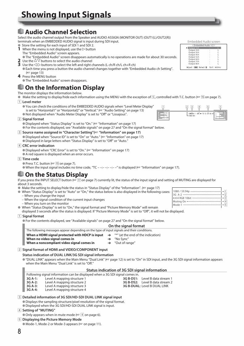
Audio Channel SelectionSelect the audio channel output from the Speaker and AUDIO ASSIGN (MONITOR OUT) (OUT1(L)/OUT2(R)) terminals when an EMBEDDED AUDIO signal is input during SDI input.l Store the setting for each input of SDI 1 and SDI 2.1 When the menu is not displayed, use the button
The “Embedded Audio” screen appears.l The “Embedded Audio” screen disappears automatically is no operations are made for about 30 seconds.
2 Use the buttons to select the audio channel3 Use the buttons to select the left and right channels (L ch/R ch/L ch+R ch)
l Each time you press a button the audio channel changes together with “Embedded Audio ch Setting”. (+ page 13)
4 Press the MENU buttonl The “Embedded Audio” screen disappears.
On the Information DisplayThe monitor displays the information below.l Make the setting to display/hide each information using the MENU with the exception of 5, controlled with T.C. button (+ t on page 7).1 Level meter
l You can check the conditions of the EMBEDDED AUDIO signals when “Level Meter Display” is set to “Horizontal1” or “Horizontal2” or “Vertical.” (+ “Audio Setting” on page 13)
l Not displayed when “Audio Meter Display” is set to “Off” or “Lissajous”.2 Signal format
l Displayed when “Status Display” is set to “On.” (+ “Information” on page 17)l For the contents displayed, see “Available signals” on page 27 and “On the signal format” below.
3 Source name assigned in “Character Setting”(+ “Information” on page 17)l Displayed when “Source ID” is set to “On” or “Auto.” (+ “Information” on page 17)l Displayed in large letters when “Status Display” is set to “Off” or “Auto.”
4 CRC error indicationl Displayed when “CRC Error” is set to “On.” (+ “Information” on page 17)l A red square is displayed when an error occurs.
5 Time codel Press T.C. button (+ t on page 7).l When the input signal includes no time code, “TC – –:– –:– –:– –” is displayed (+ “Information” on page 17).
On the Status DisplayIf you press the INPUT SELECT button (+ u on page 7) currently lit, the status of the input signal and setting of MUTING are displayed for about 3 seconds.l Make the setting to display/hide the status in “Status Display” of the “Information”. (+ page 17)l When “Status Display” is set to “Auto” or “On,” the status below is also displayed in the following cases: – When you change the input – When the signal condition of the current input changes – When you turn on the monitorl When “Status Display” is set to “On,” the signal format and “Picture Memory Mode” will remain
displayed 3 seconds after the status is displayed. If “Picture Memory Mode” is set to “Off”, it will not be displayed.1 Signal format
l For the contents displayed, see “Available signals” on page 27 and “On the signal format” below.
On the signal formatThe following messages appear depending on the type of input signals and their conditions.When a HDMI signal protected with HDCP is inputWhen no video signal comes inWhen a noncompliant video signal comes in
ÔÔÔ
“*” (at the end of the indication)“No Sync”“Out of range”
2 Signal format of HDMI and VIDEO/COMPONENT input Status indication of DUAL LINK/3G SDI signal information
l “DUAL LINK” appears when the Main Menu “Dual Link” (+ page 12) is set to “On” in SDI input, and the 3G SDI signal information appears when the Main Menu “Dual Link” is set to “Off.”
Status indication of 3G SDI signal informationFollowing signal information can be displayed when a 3G SDI signal comes in.3G A-1: Level A mapping structure 13G A-2: Level A mapping structure 23G A-3: Level A mapping structure 33G A-4: Level A mapping structure 4
3G B-DS1: Level B data stream 13G B-DS2: Level B data stream 23G B-DUAL: Level B DUAL LINK
3 Detailed information of 3G SDI/HD-SDI DUAL LINK signal inputl Displays the sampling structure/pixel resolution of the signal format.l Displayed when the 3G SDI/HD-SDI DUAL LINK signal is input.
4 Setting of “MUTING”l Only appears when in mute mode (+ 4 on page 6).
5 Displaying the Picture Memory Model Mode-1, Mode-2 or Mode-3 appears (+ on page 11).
< Embedded Audio 1/2 >Output 1ch : LOutput 2ch : LOutput 3ch : LOutput 4ch : LOutput 5ch : LOutput 6ch : LOutput 7ch : LOutput 8ch : L
Embedded Audio screen
Showing Input Signals
1080 / 59.94p3G A-24:4:4 RGB 10bitMuting OnMode-1
DT-V24G2_EN.indb 8 2016/07/27 16:37:10
99
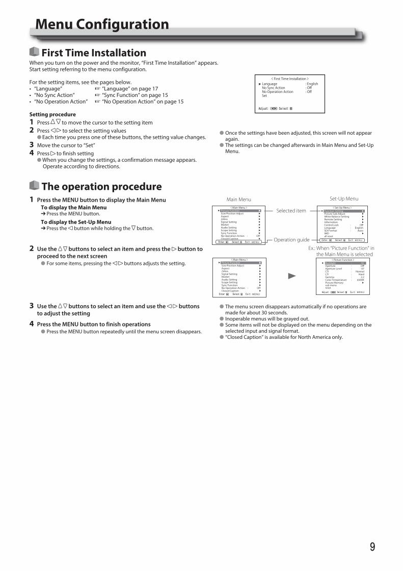
First Time InstallationWhen you turn on the power and the monitor, “First Time Installation” appears.Start setting referring to the menu configuration.
For the setting items, see the pages below.• “Language” + “Language” on page 17• “No Sync Action” + “Sync Function” on page 15• “No Operation Action” + “No Operation Action” on page 15
Setting procedure1 Press to move the cursor to the setting item2 Press to select the setting values
l Each time you press one of these buttons, the setting value changes.3 Move the cursor to “Set”4 Press to finish setting
l When you change the settings, a confirmation message appears. Operate according to directions.
The operation procedure1 Press the MENU button to display the Main Menu
To display the Main MenuÔ Press the MENU button.
To display the Set-Up MenuÔ Press the button while holding the button.
2 Use the buttons to select an item and press the button to proceed to the next screen
l For some items, pressing the buttons adjusts the setting.
3 Use the buttons to select an item and use the buttons to adjust the setting
4 Press the MENU button to finish operationsl Press the MENU button repeatedly until the menu screen disappears.
Main Menu
Selected item
Operation guide
Set-Up Menu
Ex.: When “Picture Function” in the Main Menu is selected
Menu Configuration
l The menu screen disappears automatically if no operations are made for about 30 seconds.
l Inoperable menus will be grayed out.l Some items will not be displayed on the menu depending on the
selected input and signal format.l “Closed Caption” is available for North America only.
< First Time Installation >: English: Off: Off
LanguageNo Sync ActionNo Operation ActionSet
< Main Menu >Picture Function ▶Size/Position Adjust ▶Aspect ▶Zebra ▶Signal Setting ▶Marker ▶Audio Setting ▶Scope Setting ▶Sync Function ▶No Operation Action : OffClosed Caption ▶
< Set-Up Menu >Function Setting ▶Picture Sub Adjust ▶White Balance Setting ▶Remote Setting ▶Information ▶Control Lock : OffLanguage : EnglishSDI Format : AutoIMD ▶all reset
< Picture Function >
Backlight : -02
Aperture : Off
Aperture Level : 07
CTI : Normal
LTI : Hard
Gamma : 2.2
Color Temperature : 6500K
Picture Memory ▶
sub menu
reset
< Main Menu >Picture Function ▶Size/Position Adjust ▶Aspect ▶Zebra ▶Signal Setting ▶Marker ▶Audio Setting ▶Scope Setting ▶Sync Function ▶No Operation Action : OffClosed Caption ▶
l Once the settings have been adjusted, this screen will not appear again.
l The settings can be changed afterwards in Main Menu and Set-Up Menu.
DT-V24G2_EN.indb 9 2016/07/27 16:37:12
1010
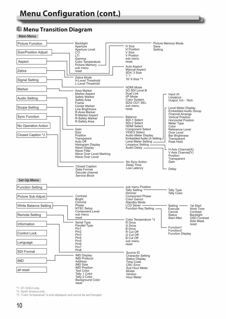
Menu Transition DiagramMain Menu
BacklightApertureAperture LevelCTILTIGammaColor TemperaturePicture Memorysub menureset
Level Meter DisplayEmbedded Audio GroupChannel ArrangeVertical PositionHorizontal PositionMeter TypeColorReference LevelOver LevelBar BrightnessTransparentPeak Hold
H Axis Channel(X)V Axis Channel(Y)PositionTransparentGain
Delay
Input chLissajousOutput 1ch - 16ch
H SizeH PositionV SizeV Postionsub menureset
Picture Memory ModeSaveSetting
HDMI Mode3G SDI Level BDual LinkI/P ModeColor SystemSDI2 OUT SELsub menureset
Area MarkerMarker AspectSafety MarkerSafety AreaFrameCenter MarkerLine BrightnessR-Area MarkerR-Marker AspectR-Safety MarkerR-Safety Area
Auto AspectManual AspectSD4:3 Size1:116:9 Size *1Zebra Mode
H-Level ThresholdL-Level Threshold
BalanceSDI-1 SelectSDI-2 SelectHDMI SelectComponent SelectVIDEO SelectAudio Meter DisplayEmbedded Audio ch SettingLevel Meter SettingLissajous SettingAudio Delay
No Sync ActionDelay TimeLow LatencyClosed Caption
Data FormatDecode channelService Block
GainSizePositionTransparentAuto OffHistogram DisplayWave DisplayWave FilterWave Over Level MarkingWave Over Level
Picture Function
Audio Setting
Sync Function
No Operation Action
Closed Caption *2
Signal Setting
Marker
Aspect
Size/Position Adjust
Scope Setting
Zebra
Set-Up Menu
ContrastBrightChromaPhaseNTSC SetupComponent Levelsub menureset Color Temperature *3
R DriveG DriveB DriveR Cut OffG Cut OffB Cut Offsub menureset
Function Setting
Picture Sub Adjust
White Balance Setting
Remote Setting
Information
Control Lock
Language
IMD
SDI Format
all reset
sub menu PositionTally SettingDimmerComponent PhaseColor GamutStandby ModeLCD SaverFunction Key Setting
SettingExecuteCancelStatusStart After
Tally TypeTally Color
1st StartWork TimeContrastBacklightOSD ContrastSide MaskresetSerial Type
Parallel TypePin1Pin2Pin3Pin4Pin5Pin6Pin7Pin8
Source IDCharacter SettingStatus DisplayTime CodeCRC ErrorSub Hour MeterModelVersionHour Meter
IMD DisplayIMD ProtocolAddressIMD SizeIMD PositionText ColorTally 1 ColorTally 2 ColorBackground Colorreset
Function1Function2Function Display
*1 : DT-V24G2 only.*2 : North America only.*3 : “Color Temperature” is only displayed, and cannot be set/changed.
Menu Configuration (cont.)
DT-V24G2_EN.indb 10 2016/07/27 16:37:12
1111
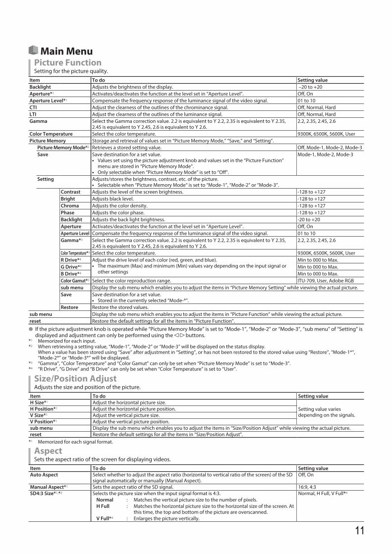
Main MenuPicture FunctionSetting for the picture quality.
Item To do Setting valueBacklight Adjusts the brightness of the display. –20 to +20Aperture*1 Activates/deactivates the function at the level set in “Aperture Level”. Off, OnAperture Level*1 Compensate the frequency response of the luminance signal of the video signal. 01 to 10CTI Adjust the clearness of the outlines of the chrominance signal. Off, Normal, HardLTI Adjust the clearness of the outlines of the luminance signal. Off, Normal, HardGamma Select the Gamma correction value. 2.2 is equivalent to Υ 2.2, 2.35 is equivalent to Υ 2.35,
2.45 is equivalent to Υ 2.45, 2.6 is equivalent to Υ 2.6.2.2, 2.35, 2.45, 2.6
Color Temperature Select the color temperature. 9300K, 6500K, 5600K, UserPicture Memory Storage and retrieval of values set in “Picture Memory Mode,” “Save,” and “Setting”.
Picture Memory Mode*2 Retrieves a stored setting value. Off, Mode-1, Mode-2, Mode-3Save Save destination for a set value.
• Values set using the picture adjustment knob and values set in the “Picture Function” menu are stored in “Picture Memory Mode”.
• Only selectable when “Picture Memory Mode” is set to “Off".
Mode-1, Mode-2, Mode-3
Setting Adjusts/stores the brightness, contrast, etc. of the picture.• Selectable when “Picture Memory Mode“ is set to “Mode-1”, “Mode-2” or “Mode-3”.
Contrast Adjusts the level of the screen brightness. -128 to +127Bright Adjusts black level. -128 to +127Chroma Adjusts the color density. -128 to +127Phase Adjusts the color phase. -128 to +127Backlight Adjusts the back light brightness. -20 to +20Aperture Activates/deactivates the function at the level set in “Aperture Level”. Off, OnAperture Level Compensate the frequency response of the luminance signal of the video signal. 01 to 10Gamma*3 Select the Gamma correction value. 2.2 is equivalent to Υ 2.2, 2.35 is equivalent to Υ 2.35,
2.45 is equivalent to Υ 2.45, 2.6 is equivalent to Υ 2.6.2.2, 2.35, 2.45, 2.6
Color Temperature*3 Select the color temperature. 9300K, 6500K, 5600K, User R Drive*4 Adjust the drive level of each color (red, green, and blue).
• The maximum (Max) and minimum (Min) values vary depending on the input signal or other settings
Min to 000 to Max.G Drive*4 Min to 000 to Max.B Drive*4 Min to 000 to Max.Color Gamut*3 Select the color reproduction range. ITU-709, User, Adobe RGBsub menu Display the sub menu which enables you to adjust the items in “Picture Memory Setting” while viewing the actual picture.Save Save destination for a set value.
• Stored in the currently selected “Mode-*”.Restore Restore the stored values.
sub menu Display the sub menu which enables you to adjust the items in “Picture Function” while viewing the actual picture.reset Restore the default settings for all the items in “Picture Function”.
l If the picture adjustment knob is operated while “Picture Memory Mode” is set to “Mode-1”, “Mode-2” or “Mode-3”, “sub menu” of “Setting” is displayed and adjustment can only be performed using the buttons.
*1 Memorized for each input.*2 When retrieving a setting value, “Mode-1”, “Mode-2” or “Mode-3” will be displayed on the status display.
When a value has been stored using “Save” after adjustment in “Setting”, or has not been restored to the stored value using “Restore”, “Mode-1*”, “Mode-2*” or “Mode-3*” will be displayed.
*3 “Gamma”, “Color Temperature” and “Color Gamut” can only be set when “Picture Memory Mode” is set to “Mode-3”. *4 “R Drive”, “G Drive” and “B Drive” can only be set when “Color Temperature” is set to “User”.
Size/Position AdjustAdjusts the size and position of the picture.
Item To do Setting valueH Size*1 Adjust the horizontal picture size.
Setting value varies depending on the signals.
H Position*1 Adjust the horizontal picture position.V Size*1 Adjust the vertical picture size.V Position*1 Adjust the vertical picture position.sub menu Display the sub menu which enables you to adjust the items in “Size/Position Adjust” while viewing the actual picture.reset Restore the default settings for all the items in “Size/Position Adjust”.
*1 Memorized for each signal format.
AspectSets the aspect ratio of the screen for displaying videos.
Item To do Setting valueAuto Aspect Select whether to adjust the aspect ratio (horizontal to vertical ratio of the screen) of the SD
signal automatically or manually (Manual Aspect).Off, On
Manual Aspect*1 Sets the aspect ratio of the SD signal. 16:9, 4:3 SD4:3 Size*1,*2 Selects the picture size when the input signal format is 4:3. Normal, H Full, V Full*4
Normal : Matches the vertical picture size to the number of pixels.H Full : Matches the horizontal picture size to the horizontal size of the screen. At
this time, the top and bottom of the picture are overscanned.V Full*4 : Enlarges the picture vertically.
DT-V24G2_EN.indb 11 2016/07/27 16:37:12
1212
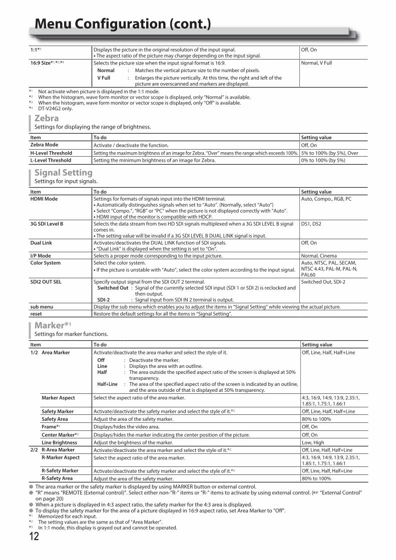
1:1*3 Displays the picture in the original resolution of the input signal.• The aspect ratio of the picture may change depending on the input signal.
Off, On
16:9 Size*1,*2,*4 Selects the picture size when the input signal format is 16:9. Normal, V FullNormal : Matches the vertical picture size to the number of pixels.V Full : Enlarges the picture vertically. At this time, the right and left of the
picture are overscanned and markers are displayed.*1 Not activate when picture is displayed in the 1:1 mode.*2 When the histogram, wave form monitor or vector scope is displayed, only “Normal” is available.*3 When the histogram, wave form monitor or vector scope is displayed, only “Off” is available.*4 DT-V24G2 only.
ZebraSettings for displaying the range of brightness.
Item To do Setting valueZebra Mode Activate / deactivate the function. Off, OnH-Level Threshold Setting the maximum brightness of an image for Zebra. “Over” means the range which exceeds 100%. 5% to 100% (by 5%), OverL-Level Threshold Setting the minimum brightness of an image for Zebra. 0% to 100% (by 5%)
Signal SettingSettings for input signals.
Item To do Setting valueHDMI Mode Settings for formats of signals input into the HDMI terminal.
• Automatically distinguishes signals when set to “Auto”. (Normally, select “Auto”)• Select “Compo.”, “RGB” or “PC” when the picture is not displayed correctly with “Auto”.• HDMI input of the monitor is compatible with HDCP.
Auto, Compo., RGB, PC
3G SDI Level B Selects the data stream from two HD SDI signals multiplexed when a 3G SDI LEVEL B signal comes in.• The setting value will be invalid if a 3G SDI LEVEL B DUAL LINK signal is input.
DS1, DS2
Dual Link Activates/deactivates the DUAL LINK function of SDI signals.• “Dual Link” is displayed when the setting is set to “On”.
Off, On
I/P Mode Selects a proper mode corresponding to the input picture. Normal, CinemaColor System Select the color system. Auto, NTSC, PAL, SECAM,
NTSC 4.43, PAL-M, PAL-N, PAL60
• If the picture is unstable with “Auto”, select the color system according to the input signal.
SDI2 OUT SEL Specify output signal from the SDI OUT 2 terminal.Switched Out : Signal of the currently selected SDI input (SDI 1 or SDI 2) is reclocked and then output.SDI-2 : Signal input from SDI IN 2 terminal is output.
Switched Out, SDI-2
sub menu Display the sub menu which enables you to adjust the items in “Signal Setting” while viewing the actual picture.reset Restore the default settings for all the items in “Signal Setting”.
Marker*1
Settings for marker functions.
Item To do Setting value1/2 Area Marker Activate/deactivate the area marker and select the style of it. Off, Line, Half, Half+Line
OffLineHalf
Half+Line
:::
:
Deactivate the marker.Displays the area with an outline.The area outside the specified aspect ratio of the screen is displayed at 50% transparency.The area of the specified aspect ratio of the screen is indicated by an outline, and the area outside of that is displayed at 50% transparency.
Marker Aspect Select the aspect ratio of the area marker. 4:3, 16:9, 14:9, 13:9, 2.35:1, 1.85:1, 1.75:1, 1.66:1
Safety Marker Activate/deactivate the safety marker and select the style of it.*2 Off, Line, Half, Half+LineSafety Area Adjust the area of the safety marker. 80% to 100%Frame*3 Displays/hides the video area. Off, On
Center Marker*3 Displays/hides the marker indicating the center position of the picture. Off, OnLine Brightness Adjust the brightness of the marker. Low, High
2/2 R-Area Marker Activate/deactivate the area marker and select the style of it.*2 Off, Line, Half, Half+LineR-Marker Aspect Select the aspect ratio of the area marker. 4:3, 16:9, 14:9, 13:9, 2.35:1,
1.85:1, 1.75:1, 1.66:1R-Safety Marker Activate/deactivate the safety marker and select the style of it.*2 Off, Line, Half, Half+LineR-Safety Area Adjust the area of the safety marker. 80% to 100%
l The area marker or the safety marker is displayed by using MARKER button or external control.l “R” means “REMOTE (External control)”. Select either non-“R-” items or “R-” items to activate by using external control. (+ “External Control”
on page 20)l When a picture is displayed in 4:3 aspect ratio, the safety marker for the 4:3 area is displayed.l To display the safety marker for the area of a picture displayed in 16:9 aspect ratio, set Area Marker to "Off".*1 Memorized for each input.*2 The setting values are the same as that of “Area Marker”.*3 In 1:1 mode, this display is grayed out and cannot be operated.
Menu Configuration (cont.)
DT-V24G2_EN.indb 12 2016/07/27 16:37:13
1313
Audio SettingSettings for AUDIO signals, EMBEDDED AUDIO signals and audio level meter signal.
Item To do Setting valueBalance Adjust the balance between the right and left speakers. L5 to L1, 0, R1 to R5
SDI-1 Select*1
SDI-2 Select*1Select the input through which audio is output. Off, Auto, Digital, Analog1,
Analog2OffAutoDigitalAnalog1Analog2
:::::
Does not output audio.Output digital audio prior to analog audio.Output audio from the SDI terminal.Output audio from the AUDIO ASSIGN (IN 1) terminal.Output audio from the AUDIO ASSIGN (IN 2) terminal.
HDMI Select Select the input through which audio is output. Off, Digital, Analog1, Analog2Off
DigitalAnalog1Analog2
::::
Does not output audio.Output audio from the HDMI terminal.Output audio from the AUDIO ASSIGN (IN 1) terminal.Output audio from the AUDIO ASSIGN (IN 2) terminal.
Component SelectVIDEO Select
Select the input through which audio is output. Off, Analog1, Analog2OffAnalog1Analog2
:::
Does not output audio.Output audio from the AUDIO ASSIGN (IN 1) terminal.Output audio from the AUDIO ASSIGN (IN 2) terminal.
Audio Meter Display Specify whether to turn off Audio Meter Display, or display the Level Meter or Lissajous. Off, Level Meter, LissajousEmbedded Audio ch Setting*1 Specify an EMBEDDED AUDIO CH.
Input ch Displays the currently selected SDI INPUT CH.Lissajous Displays the EMBEDDED AUDIO CH selected from the Lissajous screen.Output 1ch to 16ch Select a channel to output. L, R, LR, ---
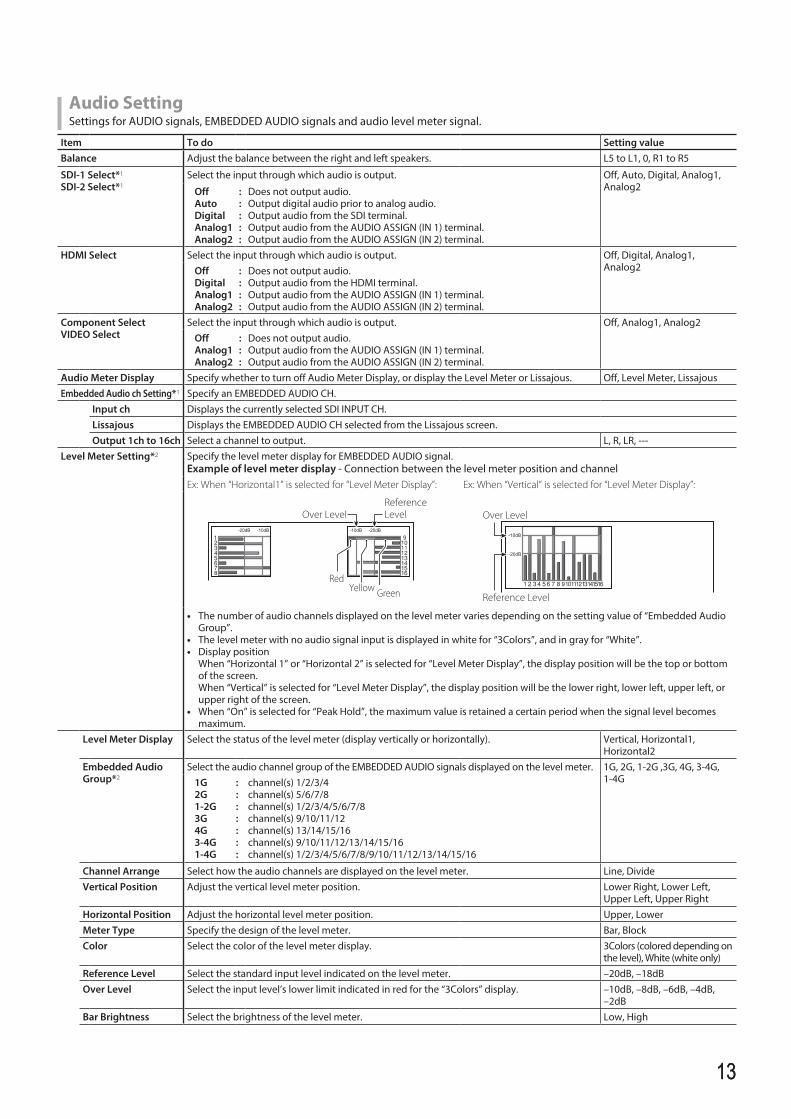
Level Meter Setting*2 Specify the level meter display for EMBEDDED AUDIO signal.Example of level meter display - Connection between the level meter position and channelEx: When “Horizontal1” is selected for “Level Meter Display”: Ex: When “Vertical” is selected for “Level Meter Display”:
-10dB -20dB-20dB -10dB
Reference LevelOver Level
GreenRed
Yellow
Over Level
Reference Level
-20dB
-10dB
• The number of audio channels displayed on the level meter varies depending on the setting value of “Embedded Audio Group”.
• The level meter with no audio signal input is displayed in white for “3Colors”, and in gray for “White”.• Display position When “Horizontal 1” or “Horizontal 2” is selected for “Level Meter Display”, the display position will be the top or bottom
of the screen. When “Vertical” is selected for “Level Meter Display”, the display position will be the lower right, lower left, upper left, or
upper right of the screen.• When “On” is selected for “Peak Hold”, the maximum value is retained a certain period when the signal level becomes
maximum.Level Meter Display Select the status of the level meter (display vertically or horizontally). Vertical, Horizontal1,
Horizontal2Embedded Audio Group*2
Select the audio channel group of the EMBEDDED AUDIO signals displayed on the level meter. 1G, 2G, 1-2G ,3G, 4G, 3-4G, 1-4G1G
2G1-2G3G4G3-4G 1-4G
:::::::
channel(s) 1/2/3/4channel(s) 5/6/7/8channel(s) 1/2/3/4/5/6/7/8channel(s) 9/10/11/12channel(s) 13/14/15/16channel(s) 9/10/11/12/13/14/15/16channel(s) 1/2/3/4/5/6/7/8/9/10/11/12/13/14/15/16
Channel Arrange Select how the audio channels are displayed on the level meter. Line, DivideVertical Position Adjust the vertical level meter position. Lower Right, Lower Left,
Upper Left, Upper RightHorizontal Position Adjust the horizontal level meter position. Upper, LowerMeter Type Specify the design of the level meter. Bar, BlockColor Select the color of the level meter display. 3Colors (colored depending on
the level), White (white only)Reference Level Select the standard input level indicated on the level meter. –20dB, –18dBOver Level Select the input level’s lower limit indicated in red for the “3Colors” display. –10dB, –8dB, –6dB, –4dB,
–2dBBar Brightness Select the brightness of the level meter. Low, High
DT-V24G2_EN.indb 13 2016/07/27 16:37:13
1414
Transparent Adjust the transparency of the level meter display against the image. Off, Background, AllPeak Hold Activates/deactivates the peak hold function of the level meter. Off, On
Lissajous Setting Lissajous setting
<Lissajous display example>
H Axis Channel(X) Select an EMBEDDED AUDIO CH to display on the horizontal axis of the Lissajous screen. 1, 2, 3, 4, 5, 6, 7, 8, 9, 10, 11, 12, 13, 14, 15, 16
V Axis Channel(Y) Select the EMBEDDED AUDIO CH to display on the vertical axis of the Lissajous screen. 1, 2, 3, 4, 5, 6, 7, 8, 9, 10, 11, 12, 13, 14, 15, 16
Position Select a position to display the screen. Lower Right, Lower Left, Upper Left, Upper Right
Transparent Set the background of the screen to translucent. Off, OnGain Specify the Lissajous gain. 0dB, +6dB, +12dB
Audio Delay Audio delay settingDelay Delay EMBEDDED AUDIO of SDI input. 0, 1, 2, 3, 4, 5, 6, 7, 8, 9, 10
*1 Operates as SDI-1 during Dual Link input.*2 Memorized for each input.
Scope Setting*1
Configure the settings for the wave form monitor, vector scope and histogram.
Item To do Setting valueGain*2 Adjust the input gain level. –10 to +10Size*3 Set the window size. Normal, LargePosition Select the window position. Lower Right, Lower Left
Upper Left, Upper RightTransparent Activates/deactivates the function to make the window translucent. Off, On
OffOn
::
NormalTranslucent
Auto Off Set the function to turn off the window automatically 15 minutes after displayed. Off, OnHistogram Display Select the signal component for the histogram display. Y, R, G, B, RGBWave Display Select a wave form to be displayed for the wave form monitor. Y, Pb, Pr (HD signal)
Y, Cb, Cr (SD signal)R, G, B (RGB signal)
Wave Filter Turn on/off the lowpass filter to put over the input wave form data. Flat (No filter)Low pass
Wave Over Level Marking Turn on/off the function to change the wave form color of signals over the value specified in “Wave Over Level”. (+ below)
Off, On
Wave Over Level Adjust the lower limit for the over level. 70 – 109
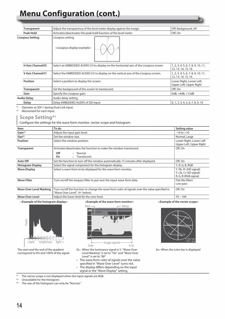
<Example of the histogram display> <Example of the wave form monitor> <Example of the vector scope>
<dark brightness light >
Pixe
ls
Image signalsStart End
Red White
Y
MgR
B
100% level75% level
CyG
Yl
The start and the end of the gradient correspond to 0% and 100% of the signal.
Ex.: When the luminance signal is Y, “Wave Over Level Marking” is set to “On” and “Wave Over Level” is set to “80”
• Thewaveformcolorofsignalsoverthevaluespecified in “Wave Over Level” turns red.
• Thedisplaydiffersdependingontheinputsignal or the “Wave Display” setting.
Ex.: When the color bar is displayed
*1 The vector scope is not displayed when the input signals are RGB.*2 Unavailable for the histogram.*3 The size of the histogram can only be “Normal.”
Y
X
Menu Configuration (cont.)
DT-V24G2_EN.indb 14 2016/07/27 16:37:14
1515
Sync FunctionSettings for the synchronization with signals.
Item To do Setting valueNo Sync Action Select the screen status when no signal is coming in. Off, Standby, Power Save
(power save mode), Gray Back (gray screen)
Delay Time Select the period until the screen status changes as selected in “No Sync Action” after signals stop coming in.
30s, 5min, 15min
Low Latency Activates/deactivates the function to shorten the time taken to display the picture (low latency function).
Off, On
• If the picture is not displayed steadily while “On” is selected, select “Off.”• While “On” is selected, the displayed picture may become unstable when an operation
using buttons on the front panel or the menu is performed, or when the signal format changes.
l When setting “No Sync Action” to “Gray Back,” the screen color changes to gray and the power consumption of the backlight is saved by half. Selecting “Power Save” (power save mode) saves more power consumption by turning off the backlight.
No Operation Action Setting values: Off, OnSetting of the function for turning the unit off (standby) automatically when no operations are made for more than 4 hours.Off: Does not turn off automaticallyOn: Turns off automaticallyl When the function is turned On, a warning message will be displayed about 3 minutes before turning off automatically.
When you turn on the unit with the function turned On, a message notifying that the setting is turned on will be displayed for about 30 seconds.
Closed Caption*1, *2
Settings for Closed Caption functions
Item To do Setting valueClosed Caption Activate/deactivate the closed caption. Off, OnData Format Select the data format of closed caption. 708, 608ANC, 608(708),
608VBI*3
Decode channel Selects the type of closed caption. CC1, CC2, CC3, CC4, Text1, Text2, Text3, Text4
Service Block Selects the type of service block. Service1, Service2, Service3, Service4, Service5
• Closed Caption does not work for all video formats.• Closed Caption does not work for the COMPO./HDMI input.• Closed Caption does not work for the SDI input formats 1035/60i, 1035/59.94i, 1080/60p, 1080/59.94p, 1080/50p and 3G SDI Level A.• Depending on signal format, there maybe a case that the closed captions are not displayed properly.• When using the 1:1 mode, closed captions may not be displayed properly.
*1 North America only.*2 Memorized for each input.*3 Displayed only when SD SDI signal is input.
Set-Up MenuFunction Setting Settings for the sub menu display, tally lamp, button lamp intensity, LCD Saver and FUNCTION button.
Item To do Setting valuesub menu Position Select the contents and displaying position of “sub menu.” Lower1, Upper1, Lower2,
Upper2Lower1 : Displays the current setting and adjustment bar at the lower part of the screen.Upper1 : Displays the current setting and adjustment bar at the upper part of the screen.Lower2 : Displays the current setting at the lower part of the screen.Upper2 : Displays the current setting at the upper part of the screen.
• The adjustment bar is not displayed for some items.Tally Setting Set the color and mode of the tally lamp using external control.
Tally Type NormalHalf
::
Light up the entire tally.Light up the left and right halves of the tally individually.
Normal, Half
Tally Color Set the tally color when “Tally Type” is set to “Normal”. Green, RedDimmer Select the intensity of the button lamps. Normal, DarkComponent Phase Deactivates the function of PHASE adjustment (Picture adjustment knob and “Picture Sub
Adjust” in Set-Up Menu) except when an NTSC signal comes in (+ on page 16).Enable, Disable
Color Gamut Select the color reproduction range. ITU-709, User, Adobe RGB
DT-V24G2_EN.indb 15 2016/07/27 16:37:14
1616
Standby Mode Select the operation status when the monitor is powered OFF (standby). Normal, Serial, SDI OutNormal
SerialSDI Out
:
::
Changes to Low Power Mode 30 seconds after powered OFF to reduce power consumption. In this case, it cannot power on by external control.Can power on by external control after powered OFF.Can power on by external control after powered OFF. Furthermore, video will be output from the SDI OUT terminal.
LCD Saver Configure the setting for reducing damage to the LCD panel for long-time use. (+ on page 19)Setting 1st Start Set the standby time. (unit: hours) 00h-24h
Work Time
Set the time for performing the function. (unit: hours) 01h-06h
Contrast Set the contrast reduction. Normal, SaveBacklight Reduce the backlight brightness. Normal, SaveOSD Contrast
Set the contrast reduction of the OSD display. Normal, Save
Side Mask Select whether to use the side mask.* The Side Mask function works no matter whether the LCD Saver is active or stopped.
Off, On
reset Restore the default settings for all the items in “LCD Saver”.Execute Execute the LCD Saver function.Cancel Stop the LCD Saver function. (“Cancel” will be grayed out during the function stop.)Status Display the LCD Saver status. Off, ReadyStart After Display required time until the LCD SAVER operation starts. (unit: hours and minutes) **h **min
Function Key Setting Specify the function assigned to the F1/F2 button.Function1Function2
Specify the function assigned to the F1/F2 button.* For details on the functions set up, see the menu description (pages 11 to 18).
- - -, Aperture, I/P Mode, Frame, Center Marker, Level Meter Display, Gamma, Color Temperature, CRC Error, Manual Aspect, Picture Memory Mode
Function Display Select whether to display the status of the assigned function when you press the F1 button. Off, Mode-1, Mode-2OffMode-1Mode-2
:::
No status display. Perform the registration function.Display the status. Perform the registration function.Display the status. Do not perform the registration function.Perform the registration function when the status is displayed and the button is pressed again.
l To display the “Function Key Setting” menu, press the button when the menu is not displayed.l About the operations of F1/F2 button Each time you press the button, the setting value for the assigned function changes in order. Ex: When “Color Temperature” is assigned 9300K 6500K 5600K User
Each time you press the button, four setting values alternate.
Picture Sub AdjustConfigure the standard level of image adjustment.
Item To do Setting valueContrast*1 Adjust the standard level for the contrast adjusted with the CONTRAST knob on the front
panel.–20 to +20
Bright*1 Adjust the standard level for the brightness adjusted with the BRIGHT knob on the front panel.
–20 to +20
Chroma*1 Adjust the standard level for the chroma adjusted with the CHROMA knob on the front panel. –20 to +20Phase*1,*2 Adjust the standard level for the phase adjusted with the PHASE knob on the front panel. –20 to +20NTSC Setup Select the set-up level of the input NTSC signal. 00 (compliant with 0 %
set-up signal), 7.5 (compliant with 7.5 % set-up signal)
Component Level Select the level of the analog component signal (480i only). B75 (compliant with BetacamVTR 7.5 % set-up signal), B00 (compliant with BetacamVTR 0 % set-up signal), SMPTE (compliant with M2VTR signals)
sub menu Display the sub menu which enables you to adjust the items in “Picture Sub Adjust” while viewing the actual picture.reset Restore the default settings for all the items in “Picture Sub Adjust”.
*1 Memorized for each input.*2 When “Component Phase” (+ page 15) is set to “Disable,” “Phase” cannot be adjusted if no NTSC signal is input.
Menu Configuration (cont.)
DT-V24G2_EN.indb 16 2016/07/27 16:37:14
1717
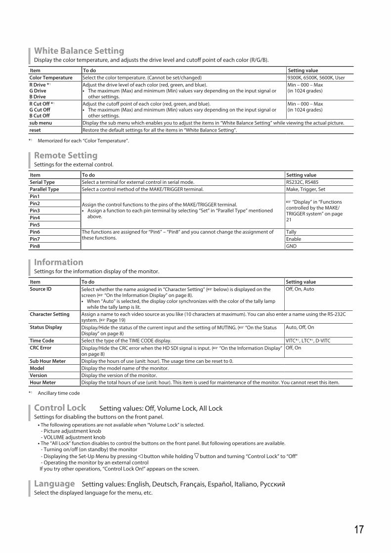
White Balance SettingDisplay the color temperature, and adjusts the drive level and cutoff point of each color (R/G/B).
Item To do Setting valueColor Temperature Select the color temperature. (Cannot be set/changed) 9300K, 6500K, 5600K, UserR Drive *1
G DriveB Drive
Adjust the drive level of each color (red, green, and blue). • The maximum (Max) and minimum (Min) values vary depending on the input signal or
other settings.
Min – 000 – Max (in 1024 grades)
R Cut Off *1
G Cut OffB Cut Off
Adjust the cutoff point of each color (red, green, and blue). • The maximum (Max) and minimum (Min) values vary depending on the input signal or
other settings.
Min – 000 – Max(in 1024 grades)
sub menu Display the sub menu which enables you to adjust the items in “White Balance Setting” while viewing the actual picture.reset Restore the default settings for all the items in “White Balance Setting”.
*1 Memorized for each “Color Temperature”.
Remote SettingSettings for the external control.
Item To do Setting valueSerial Type Select a terminal for external control in serial mode. RS232C, RS485Parallel Type Select a control method of the MAKE/TRIGGER terminal. Make, Trigger, SetPin1
Assign the control functions to the pins of the MAKE/TRIGGER terminal.• Assign a function to each pin terminal by selecting “Set” in “Parallel Type” mentioned
above.
+ “Display” in “Functions controlled by the MAKE/TRIGGER system” on page 21
Pin2Pin3Pin4Pin5Pin6 The functions are assigned for “Pin6” – “Pin8” and you cannot change the assignment of
these functions.Tally
Pin7 EnablePin8 GND
InformationSettings for the information display of the monitor.
Item To do Setting valueSource ID Select whether the name assigned in “Character Setting” (+ below) is displayed on the
screen (+ “On the Information Display” on page 8).• When “Auto” is selected, the display color synchronizes with the color of the tally lamp
while the tally lamp is lit.
Off, On, Auto
Character Setting Assign a name to each video source as you like (10 characters at maximum). You can also enter a name using the RS-232C system. (+ Page 19)
Status Display Display/Hide the status of the current input and the setting of MUTING. (+ “On the Status Display” on page 8)
Auto, Off, On
Time Code Select the type of the TIME CODE display. VITC*1, LTC*1, D-VITCCRC Error Display/Hide the CRC error when the HD SDI signal is input. (+ “On the Information Display”
on page 8)Off, On
Sub Hour Meter Display the hours of use (unit: hour). The usage time can be reset to 0.Model Display the model name of the monitor.Version Display the version of the monitor.Hour Meter Display the total hours of use (unit: hour). This item is used for maintenance of the monitor. You cannot reset this item.
*1 Ancillary time code
Control Lock Setting values: Off, Volume Lock, All LockSettings for disabling the buttons on the front panel.• The following operations are not available when “Volume Lock” is selected. - Picture adjustment knob - VOLUME adjustment knob• The “All Lock” function disables to control the buttons on the front panel. But following operations are available. - Turning on/off (on standby) the monitor - Displaying the Set-Up Menu by pressing button while holding button and turning “Control Lock” to “Off” - Operating the monitor by an external controlIf you try other operations, “Control Lock On!” appears on the screen.
Language Setting values: English, Deutsch, Français, Español, Italiano, PуccкийSelect the displayed language for the menu, etc.
DT-V24G2_EN.indb 17 2016/07/27 16:37:15
1818
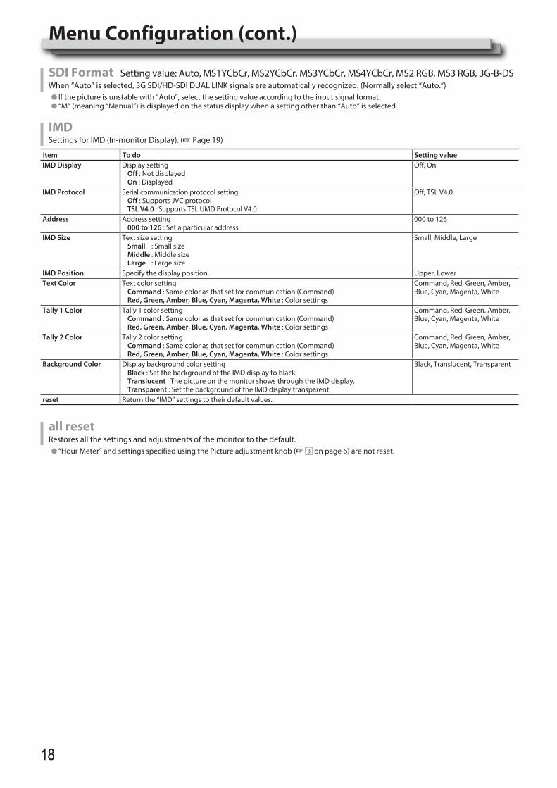
SDI Format Setting value: Auto, MS1YCbCr, MS2YCbCr, MS3YCbCr, MS4YCbCr, MS2 RGB, MS3 RGB, 3G-B-DSWhen “Auto” is selected, 3G SDI/HD-SDI DUAL LINK signals are automatically recognized. (Normally select “Auto.”)l If the picture is unstable with “Auto”, select the setting value according to the input signal format.l “M” (meaning “Manual”) is displayed on the status display when a setting other than “Auto” is selected.
IMDSettings for IMD (In-monitor Display). (+ Page 19)
Item To do Setting valueIMD Display Display setting
Off : Not displayed On : Displayed
Off, On
IMD Protocol Serial communication protocol settingOff : Supports JVC protocolTSL V4.0 : Supports TSL UMD Protocol V4.0
Off, TSL V4.0
Address Address setting000 to 126 : Set a particular address
000 to 126
IMD Size Text size settingSmall : Small sizeMiddle : Middle sizeLarge : Large size
Small, Middle, Large
IMD Position Specify the display position. Upper, LowerText Color Text color setting
Command : Same color as that set for communication (Command)Red, Green, Amber, Blue, Cyan, Magenta, White : Color settings
Command, Red, Green, Amber, Blue, Cyan, Magenta, White
Tally 1 Color Tally 1 color settingCommand : Same color as that set for communication (Command)Red, Green, Amber, Blue, Cyan, Magenta, White : Color settings
Command, Red, Green, Amber, Blue, Cyan, Magenta, White
Tally 2 Color Tally 2 color settingCommand : Same color as that set for communication (Command)Red, Green, Amber, Blue, Cyan, Magenta, White : Color settings
Command, Red, Green, Amber, Blue, Cyan, Magenta, White
Background Color Display background color settingBlack : Set the background of the IMD display to black.Translucent : The picture on the monitor shows through the IMD display.Transparent : Set the background of the IMD display transparent.
Black, Translucent, Transparent
reset Return the “IMD” settings to their default values.
all resetRestores all the settings and adjustments of the monitor to the default.l “Hour Meter” and settings specified using the Picture adjustment knob (+ 3 on page 6) are not reset.
Menu Configuration (cont.)
DT-V24G2_EN.indb 18 2016/07/27 16:37:15
1919
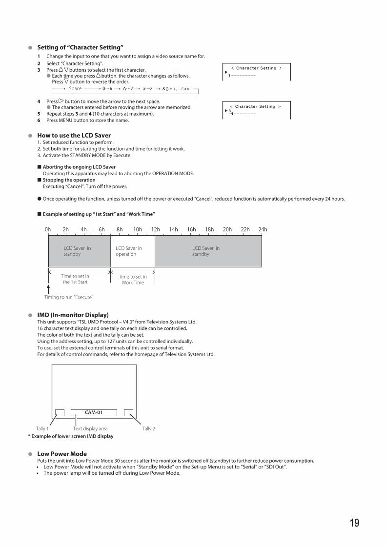
l Setting of “Character Setting”1 Change the input to one that you want to assign a video source name for.2 Select “Character Setting”.3 Press buttons to select the first character.
l Each time you press button, the character changes as follows. Press button to reverse the order.
Space
Character Setting
4 Press button to move the arrow to the next space.l The characters entered before moving the arrow are memorized.
5 Repeat steps 3 and 4 (10 characters at maximum).6 Press MENU button to store the name.
Character Setting
l How to use the LCD Saver 1. Set reduced function to perform. 2. Set both time for starting the function and time for letting it work. 3. Activate the STANDBY MODE by Execute.
n Aborting the ongoing LCD Saver Operating this apparatus may lead to aborting the OPERATION MODE. n Stopping the operation Executing “Cancel”. Turn off the power.
l Once operating the function, unless turned off the power or executed “Cancel”, reduced function is automatically performed every 24 hours.
n Example of setting up “1st Start” and “Work Time”
l IMD (In-monitor Display) This unit supports “TSL UMD Protocol – V4.0” from Television Systems Ltd. 16 character text display and one tally on each side can be controlled. The color of both the text and the tally can be set. Using the address setting, up to 127 units can be controlled individually. To use, set the external control terminals of this unit to serial format. For details of control commands, refer to the homepage of Television Systems Ltd.
l Low Power Mode Puts the unit into Low Power Mode 30 seconds after the monitor is switched off (standby) to further reduce power consumption.
• Low Power Mode will not activate when “Standby Mode” on the Set-up Menu is set to “Serial” or “SDI Out”.• The power lamp will be turned off during Low Power Mode.
Time to set in the 1st Start
0h 2h 4h 6h 8h 10h 12h 14h 16h 18h 20h 22h 24h
Timing to run "Execute"
LCD Saver in standby
LCD Saver in operation
Time to set in Work Time
CAM-01
Text display area* Example of lower screen IMD display
Tally 2Tally 1
LCD Saver in standby
DT-V24G2_EN.indb 19 2016/07/27 16:37:15
2020
External Control
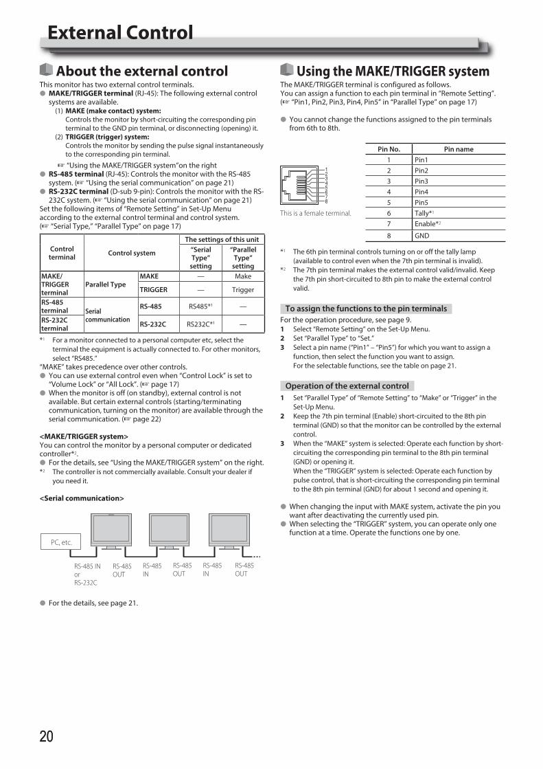
About the external controlThis monitor has two external control terminals.l MAKE/TRIGGER terminal (RJ-45): The following external control
systems are available.(1) MAKE (make contact) system: Controls the monitor by short-circuiting the corresponding pin
terminal to the GND pin terminal, or disconnecting (opening) it.(2) TRIGGER (trigger) system: Controls the monitor by sending the pulse signal instantaneously
to the corresponding pin terminal.
+ “Using the MAKE/TRIGGER system”on the rightl RS-485 terminal (RJ-45): Controls the monitor with the RS-485
system. (+ “Using the serial communication” on page 21)l RS-232C terminal (D-sub 9-pin): Controls the monitor with the RS-
232C system. (+ “Using the serial communication” on page 21)Set the following items of “Remote Setting” in Set-Up Menu according to the external control terminal and control system. (+ “Serial Type,” “Parallel Type” on page 17)
Control terminal Control system
The settings of this unit“Serial Type”
setting
“Parallel Type”
settingMAKE/TRIGGER terminal
Parallel TypeMAKE — Make
TRIGGER — Trigger
RS-485terminal Serial
communication
RS-485 RS485*1 —
RS-232C terminal RS-232C RS232C*1 —
*1 For a monitor connected to a personal computer etc, select the terminal the equipment is actually connected to. For other monitors, select “RS485.”
“MAKE” takes precedence over other controls.l You can use external control even when “Control Lock” is set to
“Volume Lock” or “All Lock”. (+ page 17)l When the monitor is off (on standby), external control is not
available. But certain external controls (starting/terminating communication, turning on the monitor) are available through the serial communication. (+ page 22)
<MAKE/TRIGGER system>You can control the monitor by a personal computer or dedicated controller*2.l For the details, see “Using the MAKE/TRIGGER system” on the right.*2 The controller is not commercially available. Consult your dealer if
you need it.
<Serial communication>
PC, etc.
RS-485 IN
RS-485 INorRS-232C
RS-485 OUT
RS-485 IN
RS-485 OUT
RS-485 OUT
l For the details, see page 21.
Using the MAKE/TRIGGER systemThe MAKE/TRIGGER terminal is configured as follows. You can assign a function to each pin terminal in “Remote Setting”. (+ “Pin1, Pin2, Pin3, Pin4, Pin5” in “Parallel Type” on page 17)
l You cannot change the functions assigned to the pin terminals from 6th to 8th.
Pin No. Pin name1 Pin12 Pin23 Pin34 Pin45 Pin5
This is a female terminal. 6 Tally*1
7 Enable*2
8 GND
*1 The 6th pin terminal controls turning on or off the tally lamp (available to control even when the 7th pin terminal is invalid).
*2 The 7th pin terminal makes the external control valid/invalid. Keep the 7th pin short-circuited to 8th pin to make the external control valid.
To assign the functions to the pin terminalsFor the operation procedure, see page 9.1 Select “Remote Setting” on the Set-Up Menu.2 Set “Parallel Type” to “Set.”3 Select a pin name (“Pin1” – “Pin5”) for which you want to assign a
function, then select the function you want to assign. For the selectable functions, see the table on page 21.
Operation of the external control1 Set “Parallel Type” of “Remote Setting” to “Make” or “Trigger” in the
Set-Up Menu.2 Keep the 7th pin terminal (Enable) short-circuited to the 8th pin
terminal (GND) so that the monitor can be controlled by the external control.
3 When the “MAKE” system is selected: Operate each function by short-circuiting the corresponding pin terminal to the 8th pin terminal (GND) or opening it.
When the “TRIGGER” system is selected: Operate each function by pulse control, that is short-circuiting the corresponding pin terminal to the 8th pin terminal (GND) for about 1 second and opening it.
l When changing the input with MAKE system, activate the pin you want after deactivating the currently used pin.
l When selecting the “TRIGGER” system, you can operate only one function at a time. Operate the functions one by one.
DT-V24G2_EN.indb 20 2016/07/27 16:37:16
2121
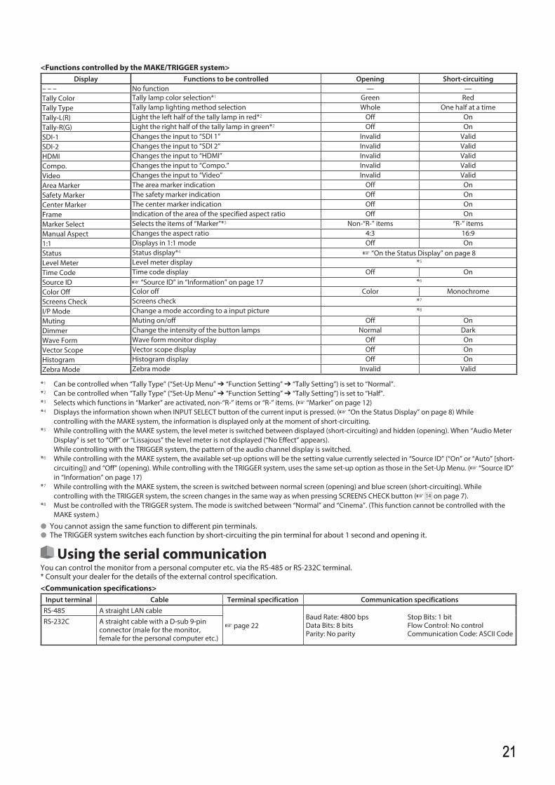
<Functions controlled by the MAKE/TRIGGER system>Display Functions to be controlled Opening Short-circuiting
– – – No function — —Tally Color Tally lamp color selection*1 Green RedTally Type Tally lamp lighting method selection Whole One half at a timeTally-L(R) Light the left half of the tally lamp in red*2 Off OnTally-R(G) Light the right half of the tally lamp in green*2 Off OnSDI-1 Changes the input to “SDI 1” Invalid ValidSDI-2 Changes the input to “SDI 2” Invalid ValidHDMI Changes the input to “HDMI” Invalid ValidCompo. Changes the input to “Compo.” Invalid ValidVideo Changes the input to “Video” Invalid ValidArea Marker The area marker indication Off OnSafety Marker The safety marker indication Off OnCenter Marker The center marker indication Off OnFrame Indication of the area of the specified aspect ratio Off OnMarker Select Selects the items of “Marker”*3 Non-“R-” items “R-” itemsManual Aspect Changes the aspect ratio 4:3 16:91:1 Displays in 1:1 mode Off OnStatus Status display*4 + “On the Status Display” on page 8Level Meter Level meter display *5
Time Code Time code display Off OnSource ID + “Source ID” in “Information” on page 17 *6
Color Off Color off Color MonochromeScreens Check Screens check *7
I/P Mode Change a mode according to a input picture *8
Muting Muting on/off Off OnDimmer Change the intensity of the button lamps Normal DarkWave Form Wave form monitor display Off OnVector Scope Vector scope display Off OnHistogram Histogram display Off OnZebra Mode Zebra mode Invalid Valid
*1 Can be controlled when “Tally Type” (“Set-Up Menu” Ô “Function Setting” Ô “Tally Setting”) is set to “Normal”.*2 Can be controlled when “Tally Type” (“Set-Up Menu” Ô “Function Setting” Ô “Tally Setting”) is set to “Half”.*3 Selects which functions in “Marker” are activated, non-“R-” items or “R-” items. (+ “Marker” on page 12)*4 Displays the information shown when INPUT SELECT button of the current input is pressed. (+ “On the Status Display” on page 8) While
controlling with the MAKE system, the information is displayed only at the moment of short-circuiting.*5 While controlling with the MAKE system, the level meter is switched between displayed (short-circuiting) and hidden (opening). When “Audio Meter
Display” is set to “Off” or “Lissajous” the level meter is not displayed (“No Effect” appears). While controlling with the TRIGGER system, the pattern of the audio channel display is switched.*6 While controlling with the MAKE system, the available set-up options will be the setting value currently selected in “Source ID” (“On” or “Auto” [short-
circuiting]) and “Off” (opening). While controlling with the TRIGGER system, uses the same set-up option as those in the Set-Up Menu. (+ “Source ID” in “Information” on page 17)
*7 While controlling with the MAKE system, the screen is switched between normal screen (opening) and blue screen (short-circuiting). While controlling with the TRIGGER system, the screen changes in the same way as when pressing SCREENS CHECK button (+ r on page 7).
*8 Must be controlled with the TRIGGER system. The mode is switched between “Normal” and “Cinema”. (This function cannot be controlled with the MAKE system.)
l You cannot assign the same function to different pin terminals.l The TRIGGER system switches each function by short-circuiting the pin terminal for about 1 second and opening it.
Using the serial communicationYou can control the monitor from a personal computer etc. via the RS-485 or RS-232C terminal.* Consult your dealer for the details of the external control specification.<Communication specifications>
Input terminal Cable Terminal specification Communication specificationsRS-485 A straight LAN cable
+ page 22Baud Rate: 4800 bps Stop Bits: 1 bitData Bits: 8 bits Flow Control: No controlParity: No parity Communication Code: ASCII Code
RS-232C A straight cable with a D-sub 9-pin connector (male for the monitor, female for the personal computer etc.)
DT-V24G2_EN.indb 21 2016/07/27 16:37:16
2222
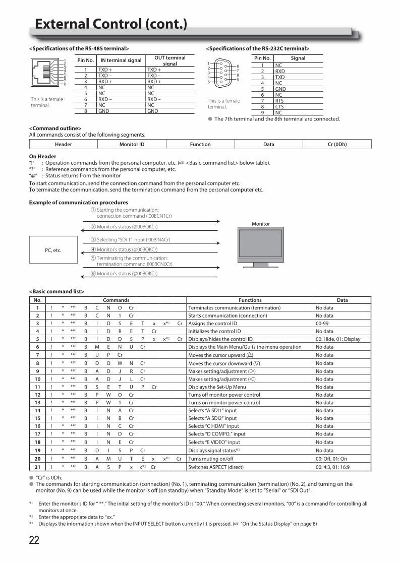
<Specifications of the RS-485 terminal>
Pin No. IN terminal signal OUT terminalsignal
1 TXD + TXD +2 TXD – TXD –3 RXD + RXD +4 NC NC
This is a female terminal.
5 NC NC6 RXD – RXD –7 NC NC8 GND GND
<Specifications of the RS-232C terminal>
Pin No. Signal1 NC2 RXD3 TXD4 NC5 GND
This is a female terminal.
6 NC7 RTS8 CTS9 NC
l The 7th terminal and the 8th terminal are connected.
<Command outline>All commands consist of the following segments.
Header Monitor ID Function Data Cr (0Dh)
On Header“!” : Operation commands from the personal computer, etc. (+ <Basic command list> below table).“?” : Reference commands from the personal computer, etc.“@” : Status returns from the monitorTo start communication, send the connection command from the personal computer etc.To terminate the communication, send the termination command from the personal computer etc.
Example of communication procedures1 Starting the communication:
connection command (!00BCN1Cr)
3 Selecting “SDI 1” input (!00BINACr)
5 Terminating the communication: termination command (!00BCN0Cr)
6 Monitor’s status (@00BOKCr)
4 Monitor’s status (@00BOKCr)
2 Monitor’s status (@00BOKCr)
PC, etc.
Monitor
<Basic command list>No. Commands Functions Data
1 ! * **1 B C N O Cr Terminates communication (termination) No data2 ! * **1 B C N 1 Cr Starts communication (connection) No data3 ! * **1 B I D S E T x x*2 Cr Assigns the control ID 00-994 ! * **1 B I D R E T Cr Initializes the control ID No data5 ! * **1 B I D D S P x x*2 Cr Displays/hides the control ID 00: Hide, 01: Display6 ! * **1 B M E N U Cr Displays the Main Menu/Quits the menu operation No data
7 ! * **1 B U P Cr Moves the cursor upward ( ) No data
8 ! * **1 B D O W N Cr Moves the cursor downward ( ) No data
9 ! * **1 B A D J R Cr Makes setting/adjustment ( ) No data10 ! * **1 B A D J L Cr Makes setting/adjustment ( ) No data11 ! * **1 B S E T U P Cr Displays the Set-Up Menu No data12 ! * **1 B P W O Cr Turns off monitor power control No data13 ! * **1 B P W 1 Cr Turns on monitor power control No data14 ! * **1 B I N A Cr Selects “A SDI1” input No data15 ! * **1 B I N B Cr Selects “A SDI2” input No data16 ! * **1 B I N C Cr Selects “C HDMI” input No data17 ! * **1 B I N D Cr Selects “D COMPO.” input No data
18 ! * **1 B I N E Cr Selects “E VIDEO” input No data
19 ! * **1 B D I S P Cr Displays signal status*3 No data
20 ! * **1 B A M U T E x x*2 Cr Turns muting on/off 00: Off, 01: On
21 ! * **1 B A S P x x*2 Cr Switches ASPECT (direct) 00: 4:3, 01: 16:9
l “Cr” is 0Dh.l The commands for starting communication (connection) (No. 1), terminating communication (termination) (No. 2), and turning on the
monitor (No. 9) can be used while the monitor is off (on standby) when “Standby Mode” is set to “Serial” or “SDI Out”.
*1 Enter the monitor’s ID for “ **.” The initial setting of the monitor’s ID is “00.” When connecting several monitors, “00” is a command for controlling all monitors at once.
*2 Enter the appropriate data to “xx.” *3 Displays the information shown when the INPUT SELECT button currently lit is pressed. (+ “On the Status Display” on page 8)
External Control (cont.)
DT-V24G2_EN.indb 22 2016/07/27 16:37:17
2323
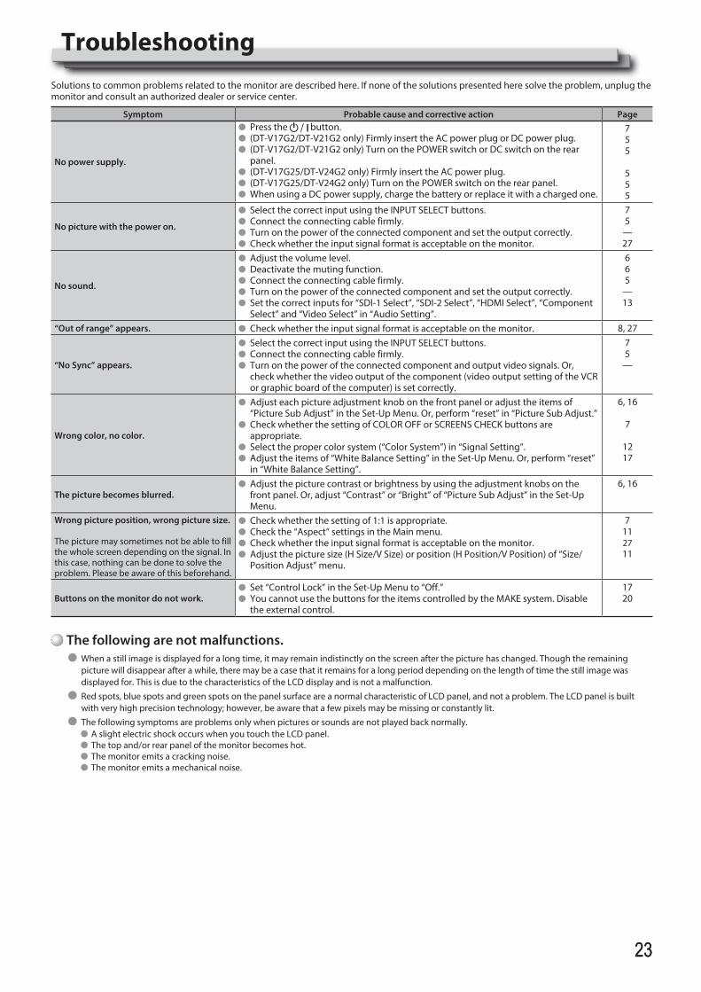
TroubleshootingSolutions to common problems related to the monitor are described here. If none of the solutions presented here solve the problem, unplug the monitor and consult an authorized dealer or service center.
Symptom Probable cause and corrective action Page
No power supply.
l Press the button.l (DT-V17G2/DT-V21G2 only) Firmly insert the AC power plug or DC power plug.l (DT-V17G2/DT-V21G2 only) Turn on the POWER switch or DC switch on the rear
panel.l (DT-V17G25/DT-V24G2 only) Firmly insert the AC power plug.l (DT-V17G25/DT-V24G2 only) Turn on the POWER switch on the rear panel.l When using a DC power supply, charge the battery or replace it with a charged one.
755
555
No picture with the power on.
l Select the correct input using the INPUT SELECT buttons. l Connect the connecting cable firmly.l Turn on the power of the connected component and set the output correctly.l Check whether the input signal format is acceptable on the monitor.
75
—27
No sound.
l Adjust the volume level.l Deactivate the muting function.l Connect the connecting cable firmly. l Turn on the power of the connected component and set the output correctly.l Set the correct inputs for “SDI-1 Select”, “SDI-2 Select”, “HDMI Select”, “Component
Select” and “Video Select” in “Audio Setting”.
665
—13
“Out of range” appears. l Check whether the input signal format is acceptable on the monitor. 8, 27
“No Sync” appears.
l Select the correct input using the INPUT SELECT buttons.l Connect the connecting cable firmly. l Turn on the power of the connected component and output video signals. Or,
check whether the video output of the component (video output setting of the VCR or graphic board of the computer) is set correctly.
75
—
Wrong color, no color.
l Adjust each picture adjustment knob on the front panel or adjust the items of “Picture Sub Adjust” in the Set-Up Menu. Or, perform “reset” in “Picture Sub Adjust.”
l Check whether the setting of COLOR OFF or SCREENS CHECK buttons are appropriate.
l Select the proper color system (“Color System”) in “Signal Setting”.l Adjust the items of “White Balance Setting” in the Set-Up Menu. Or, perform “reset”
in “White Balance Setting”.
6, 16
7
1217
The picture becomes blurred.l Adjust the picture contrast or brightness by using the adjustment knobs on the
front panel. Or, adjust “Contrast” or “Bright” of “Picture Sub Adjust” in the Set-Up Menu.
6, 16
Wrong picture position, wrong picture size.
The picture may sometimes not be able to fill the whole screen depending on the signal. In this case, nothing can be done to solve the problem. Please be aware of this beforehand.
l Check whether the setting of 1:1 is appropriate.l Check the “Aspect” settings in the Main menu.l Check whether the input signal format is acceptable on the monitor.l Adjust the picture size (H Size/V Size) or position (H Position/V Position) of “Size/
Position Adjust” menu.
7112711
Buttons on the monitor do not work.l Set “Control Lock” in the Set-Up Menu to “Off.”l You cannot use the buttons for the items controlled by the MAKE system. Disable
the external control.
1720
The following are not malfunctions.l When a still image is displayed for a long time, it may remain indistinctly on the screen after the picture has changed. Though the remaining
picture will disappear after a while, there may be a case that it remains for a long period depending on the length of time the still image was displayed for. This is due to the characteristics of the LCD display and is not a malfunction.
l Red spots, blue spots and green spots on the panel surface are a normal characteristic of LCD panel, and not a problem. The LCD panel is built with very high precision technology; however, be aware that a few pixels may be missing or constantly lit.
l The following symptoms are problems only when pictures or sounds are not played back normally.l A slight electric shock occurs when you touch the LCD panel.l The top and/or rear panel of the monitor becomes hot.l The monitor emits a cracking noise.l The monitor emits a mechanical noise.
DT-V24G2_EN.indb 23 2016/07/27 16:37:17
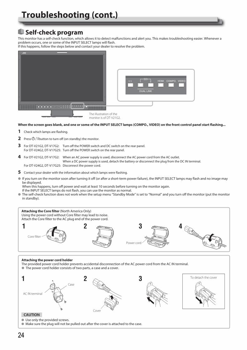
2424
Self-check programThis monitor has a self-check function, which allows it to detect malfunctions and alert you. This makes troubleshooting easier. Whenever a problem occurs, one or some of the INPUT SELECT lamps will flash. If this happens, follow the steps below and contact your dealer to resolve the problem.
The illustration of the monitor is of DT-V21G2.
When the screen goes blank, and one or some of the INPUT SELECT lamps (COMPO., VIDEO) on the front control panel start flashing...
1 Check which lamps are flashing.
2 Press button to turn off (on standby) the monitor.
3 For DT-V21G2, DT-V17G2: Turn off the POWER switch and DC switch on the rear panel. For DT-V24G2, DT-V17G25: Turn off the POWER switch on the rear panel.
4 For DT-V21G2, DT-V17G2: When an AC power supply is used, disconnect the AC power cord from the AC outlet. When a DC power supply is used, detach the battery or disconnect the plug from the DC IN terminal. For DT-V24G2, DT-V17G25: Disconnect the power cord.
5 Contact your dealer with the information about which lamps were flashing.
l If you turn on the monitor soon after turning it off (or after a short-term power failure), the INPUT SELECT lamps may flash and no image may be displayed.
When this happens, turn off power and wait at least 10 seconds before turning on the monitor again. If the INPUT SELECT lamps do not flash, you can use the monitor as normal.l The self-check function does not work when the setup menu “Standby Mode” is set to “Normal” and you turn off the monitor (put the monitor
in standby).
Cover
2
AC IN terminal
Case1
CAUTIONl Use only the provided screws.l Make sure the plug will not be pulled out after the cover is attached to the case.
Attaching the power cord holderThe provided power cord holder prevents accidental disconnection of the AC power cord from the AC IN terminal.l The power cord holder consists of two parts, a case and a cover.
To detach the cover3
Troubleshooting (cont.)
21
Attaching the Core filter (North America Only)Using the power cord without Core filter may lead to noise.Attach the Core filter to the AC plug end of the power cord.
3 4Core filter
Power cord
DT-V24G2_EN.indb 24 2016/07/27 16:37:19
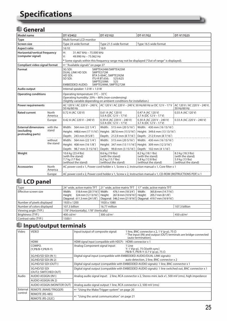
2525
Specifications
GeneralModel name DT-V24G2 DT-V21G2 DT-V17G2 DT-V17G25Type Multi format LCD monitorScreen size Type 24 wide format Type 21.5 wide format Type 16.5 wide formatAspect ratio 16:10 16:9Horizontal/vertical frequency (computer signal)
H: 31.467 kHz – 75.000 kHzV: 49.990 Hz – 75.062 Hz* Some signals within this frequency range may not be displayed (“Out of range” is displayed).
Compliant video signal format + “Available signals” on page 27Format 3G SDI: SMPTE424M/SMPTE425M
DUAL LINK HD SDI: SMPTE372MHD SDI: BTA S-004C, SMPTE292MSD SDI: ITU-R BT.656: 525/625 SMPTE259M: 525EMBEDDED AUDIO: SMPTE299M, SMPTE272M
Audio output Internal speaker: 1.0 W + 1.0 W
Operating conditions Operating temperature: 5°C – 35°COperating humidity: 20% – 80% (non-condensing)(Slightly variable depending on ambient conditions for installation.)
Power requirements AC 120 V / AC 220 V – 240 V, 50 Hz/60 Hz
AC 120 V / AC 220 V – 240 V, 50 Hz/60 Hz or DC 12 V – 17 V AC 120 V / AC 220 V – 240 V, 50 Hz/60 Hz
Rated current North America
0.72 A (AC 120 V) 0.61 A (AC 120 V)5.0 A (DC 12 V – 17 V)
0.47 A (AC 120 V)3.7 A (DC 12 V – 17 V)
0.55 A (AC 120 V)
Europe 0.42 A (AC 220 V – 240 V) 0.39 A (AC 220 V – 240 V)5.0 A (DC 12 V – 17 V)
0.30 A (AC 220 V – 240 V)3.7 A (DC 12 V – 17 V)
0.33 A (AC 220 V – 240 V)
External dimensions(excluding protruding parts)
with the stand
Width: 564 mm (22 1/4˝) Width: 515 mm (20 5/16˝) Width: 430 mm (16 15/16˝)Height: 448.6 mm (17 11/16˝) Height: 387.6 mm (15 5/16˝) Height: 349.6 mm (13 13/16˝)Depth: 243 mm (9 5/8˝) Depth: 212.9 mm (8 7/16˝) Depth: 212.9 mm (8 7/16˝)
without the stand
Width: 564 mm (22 1/4˝) Width: 515 mm (20 5/16˝) Width: 430 mm (16 15/16˝)Height: 408 mm (16 1/8˝) Height: 347 mm (13 11/16˝) Height: 309 mm (12 3/16˝)Depth: 98.7 mm (3 15/16˝) Depth: 99.8 mm (3 15/16˝) Depth: 102 mm (4 1/16˝)
Weight 10.6 kg (23.4 lbs) (with the stand)7.7 kg (17 lbs) (without the stand)
8.6 kg (19 lbs) (with the stand)6.2 kg (13.7 lbs) (without the stand)
8.2 kg (18.1 lbs) (with the stand)5.8 kg (12.8 lbs) (without the stand)
8.3 kg (18.3 lbs) (with the stand)5.9 kg (13 lbs) (without the stand)
Accessories North America
AC power cord x 1, Power cord holder x 1, Screw x 2, Instruction manual x 1, Core filter x 1
Europe AC power cord x 2, Power cord holder x 1, Screw x 2, Instruction manual x 1, CD-ROM (INSTRUCTIONS PDF) x 1
LCD panelType 24˝ wide, active matrix TFT 21˝ wide, active matrix TFT 17˝ wide, active matrix TFTEffective screen size Width: 518.4 mm (20 7/16˝)
Height: 324 mm (12 13/16˝)Diagonal: 611.3 mm (24 1/8˝)
Width: 476.1 mm (18 3/4˝)Height: 267.8 mm (10 9/16˝)Diagonal: 546.2 mm (21 9/16˝)
Width: 365.8 mm (14 7/16˝)Height: 205.7 mm (8 1/8˝)Diagonal: 419.7 mm (16 9/16˝)
Number of pixels displayed 1920 x 1200 1920 x 1080Number of colors displayed 107.3 billion 16.77 million 107.3 billionViewing angle (TYP.) 178° (Horizontally), 178° (Vertically)Brightness (TYP.) 400 cd/m2 300 cd/m2 450 cd/m2
Contrast ratio (TYP.) 1500:1
Input/output terminalsVideo VIDEO Input/output of composite signal: 1 line, BNC connector x 2, 1 V (p-p), 75 Ω
* The input (IN) and output (OUT) terminals are bridge-connected (auto termination).
HDMI HDMI signal input (compatible with HDCP): HDMI connector x 1COMPO. (Y,PB/B-Y,PR/R-Y)
Analog Component signal input: 1 LineY: 1 V(p-p), 75 Ω(with sync)PB/B-Y, PR/R-Y: 0.7 V (p-p), 75 Ω
3G/HD/SD SDI (IN 1) Digital signal input (compatible with EMBEDDED AUDIO/DUAL LINK signals): auto detection, 2 line, BNC connector x 23G/HD/SD SDI (IN 2)
3G/HD/SD SDI (OUT1) Digital signal output (compatible with EMBEDDED AUDIO signals): 1 line, BNC connector x 1
3G/HD/SD SDI (OUT2: SWITCHED OUT)
Digital signal output (compatible with EMBEDDED AUDIO signals): 1 line switched out, BNC connector x 1
Audio AUDIO ASSIGN (IN1) Analog audio signal input: 2 line, RCA connector x 2, Stereo mini Jack x1, 500 mV (rms), high impedanceAUDIO ASSIGN (IN 2)AUDIO ASSIGN (MONITOR OUT) Analog audio signal output: 1 line, RCA connector x 2, 500 mV (rms)
External control
REMOTE (MAKE/TRIGGER) + “Using the Make/Trigger system” on page 20REMOTE (RS-485)
+ “Using the serial communication” on page 21REMOTE (RS-232C)
DT-V24G2_EN.indb 25 2016/07/27 16:37:19
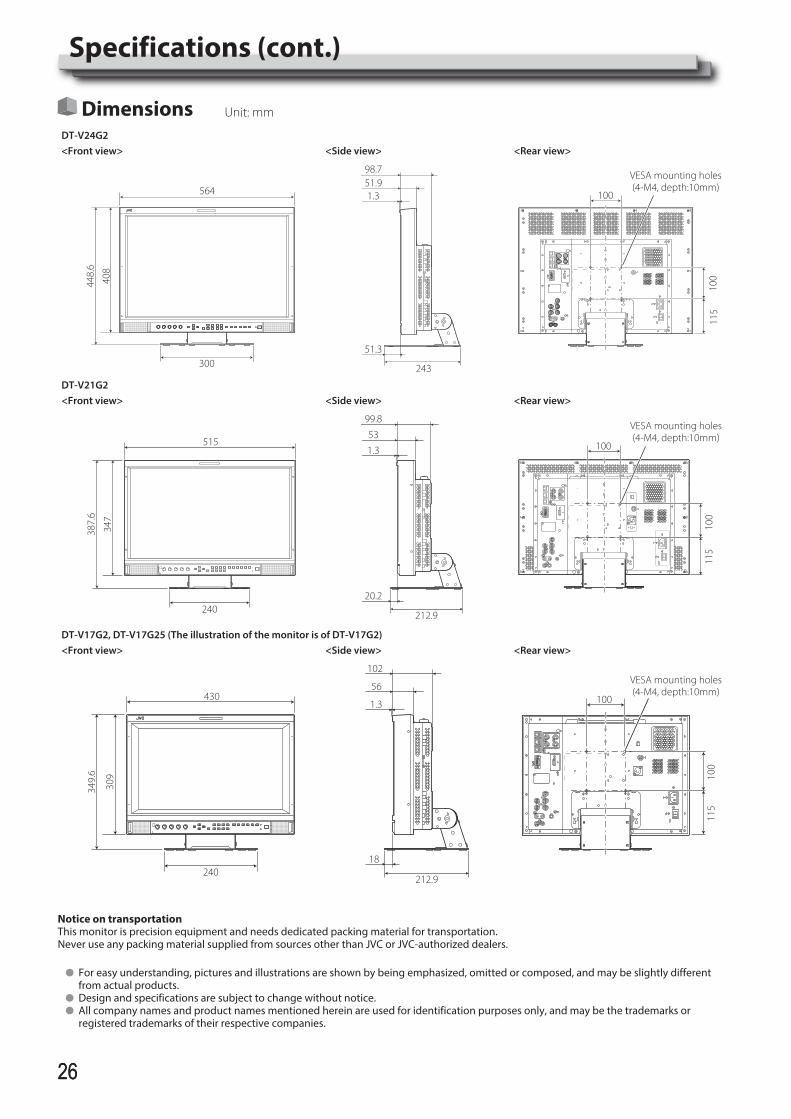
2626
Notice on transportationThis monitor is precision equipment and needs dedicated packing material for transportation.Never use any packing material supplied from sources other than JVC or JVC-authorized dealers.
l For easy understanding, pictures and illustrations are shown by being emphasized, omitted or composed, and may be slightly different from actual products.
l Design and specifications are subject to change without notice.l All company names and product names mentioned herein are used for identification purposes only, and may be the trademarks or
registered trademarks of their respective companies.
Dimensions Unit: mm
DT-V24G2<Front view> <Side view> <Rear view>
564
300
408
448.
6
243
51.998.7
1.3
51.3
VESA mounting holes(4-M4, depth:10mm)
100
100
115
DT-V21G2<Front view> <Side view> <Rear view>
515
240
347
387.
6
212.9
53
99.8
1.3
20.2
VESA mounting holes(4-M4, depth:10mm)
100
100
115
DT-V17G2, DT-V17G25 (The illustration of the monitor is of DT-V17G2)<Front view> <Side view> <Rear view>
430
240
309
349.
6
212.9
56
102
1.3
18
VESA mounting holes(4-M4, depth:10mm)
10010
011
5
Specifications (cont.)
DT-V24G2_EN.indb 26 2016/07/27 16:37:21
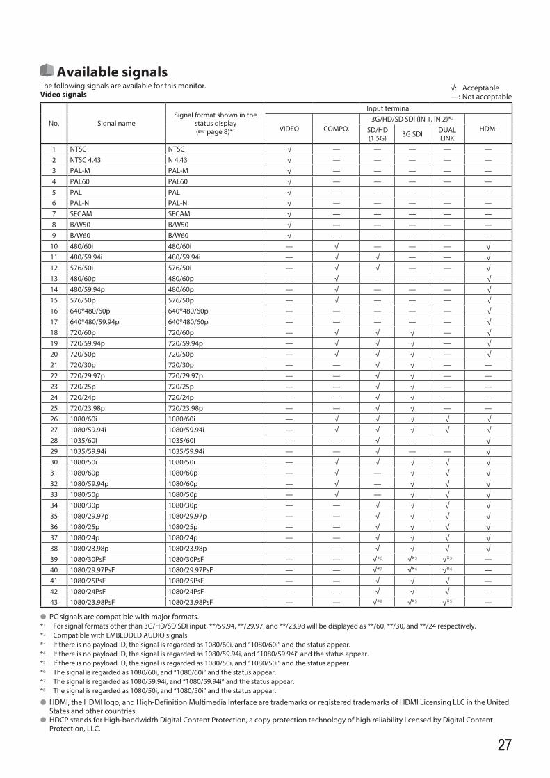
2727
Available signalsThe following signals are available for this monitor.Video signals
No. Signal nameSignal format shown in the
status display (+ page 8)*1
Input terminal
VIDEO COMPO.3G/HD/SD SDI (IN 1, IN 2)*2
HDMISD/HD(1.5G) 3G SDI DUAL
LINK1 NTSC NTSC √ — — — — —2 NTSC 4.43 N 4.43 √ — — — — —3 PAL-M PAL-M √ — — — — —4 PAL60 PAL60 √ — — — — —5 PAL PAL √ — — — — —6 PAL-N PAL-N √ — — — — —7 SECAM SECAM √ — — — — —8 B/W50 B/W50 √ — — — — —9 B/W60 B/W60 √ — — — — —
10 480/60i 480/60i — √ — — — √11 480/59.94i 480/59.94i — √ √ — — √12 576/50i 576/50i — √ √ — — √13 480/60p 480/60p — √ — — — √14 480/59.94p 480/60p — √ — — — √15 576/50p 576/50p — √ — — — √16 640*480/60p 640*480/60p — — — — — √17 640*480/59.94p 640*480/60p — — — — — √18 720/60p 720/60p — √ √ √ — √19 720/59.94p 720/59.94p — √ √ √ — √20 720/50p 720/50p — √ √ √ — √21 720/30p 720/30p — — √ √ — —22 720/29.97p 720/29.97p — — √ √ — —23 720/25p 720/25p — — √ √ — —24 720/24p 720/24p — — √ √ — —25 720/23.98p 720/23.98p — — √ √ — —26 1080/60i 1080/60i — √ √ √ √ √27 1080/59.94i 1080/59.94i — √ √ √ √ √28 1035/60i 1035/60i — — √ — — √29 1035/59.94i 1035/59.94i — — √ — — √30 1080/50i 1080/50i — √ √ √ √ √31 1080/60p 1080/60p — √ — √ √ √32 1080/59.94p 1080/60p — √ — √ √ √33 1080/50p 1080/50p — √ — √ √ √34 1080/30p 1080/30p — — √ √ √ √35 1080/29.97p 1080/29.97p — — √ √ √ √36 1080/25p 1080/25p — — √ √ √ √37 1080/24p 1080/24p — — √ √ √ √38 1080/23.98p 1080/23.98p — — √ √ √ √39 1080/30PsF 1080/30PsF — — √*6 √*3 √*3 —40 1080/29.97PsF 1080/29.97PsF — — √*7 √*4 √*4 —41 1080/25PsF 1080/25PsF — — √ √ √ —42 1080/24PsF 1080/24PsF — — √ √ √ —43 1080/23.98PsF 1080/23.98PsF — — √*8 √*5 √*5 —
l PC signals are compatible with major formats.*1 For signal formats other than 3G/HD/SD SDI input, **/59.94, **/29.97, and **/23.98 will be displayed as **/60, **/30, and **/24 respectively.*2 Compatible with EMBEDDED AUDIO signals.*3 If there is no payload ID, the signal is regarded as 1080/60i, and “1080/60i” and the status appear.*4 If there is no payload ID, the signal is regarded as 1080/59.94i, and “1080/59.94i” and the status appear.*5 If there is no payload ID, the signal is regarded as 1080/50i, and “1080/50i” and the status appear.*6 The signal is regarded as 1080/60i, and “1080/60i” and the status appear.*7 The signal is regarded as 1080/59.94i, and “1080/59.94i” and the status appear.*8 The signal is regarded as 1080/50i, and “1080/50i” and the status appear.
l HDMI, the HDMI logo, and High-Definition Multimedia Interface are trademarks or registered trademarks of HDMI Licensing LLC in the United States and other countries.
l HDCP stands for High-bandwidth Digital Content Protection, a copy protection technology of high reliability licensed by Digital Content Protection, LLC.
√: Acceptable—: Not acceptable
DT-V24G2_EN.indb 27 2016/07/27 16:37:22
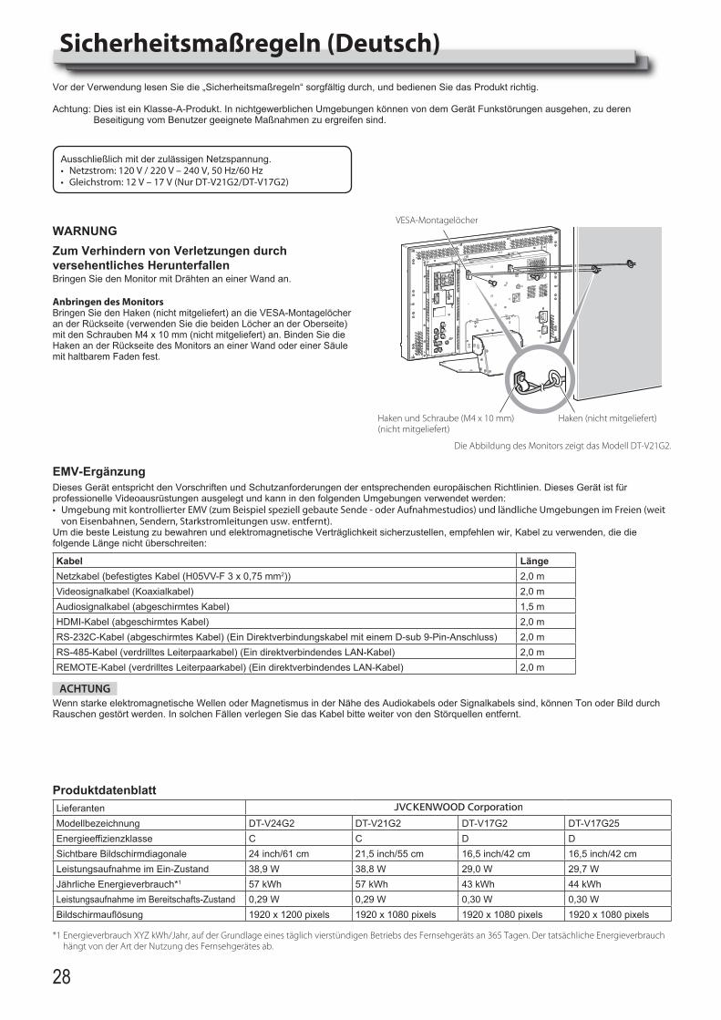
28
Sicherheitsmaßregeln (Deutsch)Vor der Verwendung lesen Sie die „Sicherheitsmaßregeln“ sorgfältig durch, und bedienen Sie das Produkt richtig.
Achtung: Dies ist ein Klasse-A-Produkt. In nichtgewerblichen Umgebungen können von dem Gerät Funkstörungen ausgehen, zu deren Beseitigung vom Benutzer geeignete Maßnahmen zu ergreifen sind.
Ausschließlich mit der zulässigen Netzspannung.• Netzstrom: 120 V / 220 V – 240 V, 50 Hz/60 Hz• Gleichstrom: 12 V – 17 V (Nur DT-V21G2/DT-V17G2)
WARNUNGZum Verhindern von Verletzungen durch versehentliches HerunterfallenBringen Sie den Monitor mit Drähten an einer Wand an.
Anbringen des MonitorsBringen Sie den Haken (nicht mitgeliefert) an die VESA-Montagelöcher an der Rückseite (verwenden Sie die beiden Löcher an der Oberseite) mit den Schrauben M4 x 10 mm (nicht mitgeliefert) an. Binden Sie die Haken an der Rückseite des Monitors an einer Wand oder einer Säule mit haltbarem Faden fest.
Haken und Schraube (M4 x 10 mm) (nicht mitgeliefert)
Haken (nicht mitgeliefert)
VESA-Montagelöcher
Die Abbildung des Monitors zeigt das Modell DT-V21G2.
EMV-ErgänzungDieses Gerät entspricht den Vorschriften und Schutzanforderungen der entsprechenden europäischen Richtlinien. Dieses Gerät ist für professionelle Videoausrüstungen ausgelegt und kann in den folgenden Umgebungen verwendet werden:• Umgebung mit kontrollierter EMV (zum Beispiel speziell gebaute Sende - oder Aufnahmestudios) und ländliche Umgebungen im Freien (weit
von Eisenbahnen, Sendern, Starkstromleitungen usw. entfernt).Um die beste Leistung zu bewahren und elektromagnetische Verträglichkeit sicherzustellen, empfehlen wir, Kabel zu verwenden, die die folgende Länge nicht überschreiten:
Kabel LängeNetzkabel (befestigtes Kabel (H05VV-F 3 x 0,75 mm2)) 2,0 mVideosignalkabel (Koaxialkabel) 2,0 mAudiosignalkabel (abgeschirmtes Kabel) 1,5 mHDMI-Kabel (abgeschirmtes Kabel) 2,0 mRS-232C-Kabel (abgeschirmtes Kabel) (Ein Direktverbindungskabel mit einem D-sub 9-Pin-Anschluss) 2,0 mRS-485-Kabel (verdrilltes Leiterpaarkabel) (Ein direktverbindendes LAN-Kabel) 2,0 mREMOTE-Kabel (verdrilltes Leiterpaarkabel) (Ein direktverbindendes LAN-Kabel) 2,0 m
ACHTUNGWenn starke elektromagnetische Wellen oder Magnetismus in der Nähe des Audiokabels oder Signalkabels sind, können Ton oder Bild durch Rauschen gestört werden. In solchen Fällen verlegen Sie das Kabel bitte weiter von den Störquellen entfernt.
ProduktdatenblattLieferantenModellbezeichnung DT-V24G2 DT-V21G2 DT-V17G2 DT-V17G25Energieeffizienzklasse C C D DSichtbare Bildschirmdiagonale 24 inch/61 cm 21,5 inch/55 cm 16,5 inch/42 cm 16,5 inch/42 cmLeistungsaufnahme im Ein-Zustand 38,9 W 38,8 W 29,0 W 29,7 WJährliche Energieverbrauch*1 57 kWh 57 kWh 43 kWh 44 kWhLeistungsaufnahme im Bereitschafts-Zustand 0,29 W 0,29 W 0,30 W 0,30 WBildschirmauflösung 1920 x 1200 pixels 1920 x 1080 pixels 1920 x 1080 pixels 1920 x 1080 pixels
*1 Energieverbrauch XYZ kWh/Jahr, auf der Grundlage eines täglich vierstündigen Betriebs des Fernsehgeräts an 365 Tagen. Der tatsächliche Energieverbrauch hängt von der Art der Nutzung des Fernsehgerätes ab.
DT-V24G2_EN.indb 28 2016/07/27 16:37:24
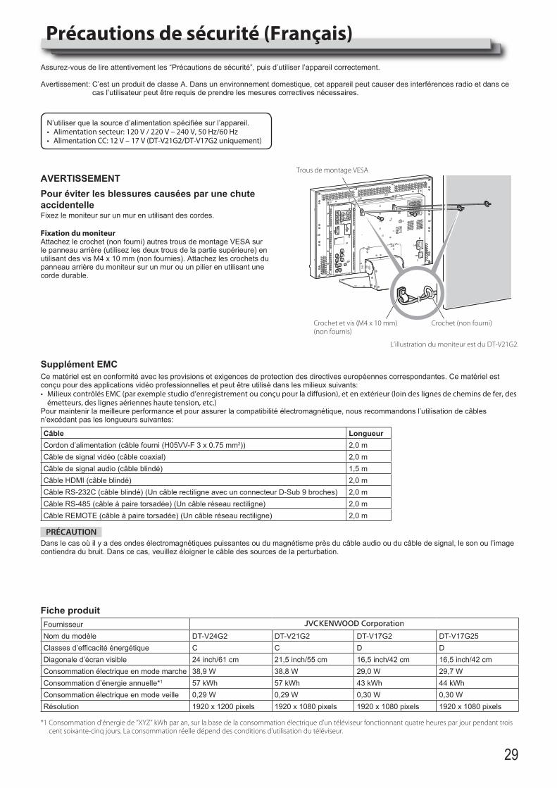
29
Précautions de sécurité (Français)Assurez-vous de lire attentivement les “Précautions de sécurité”, puis d’utiliser l’appareil correctement.
Avertissement: C’est un produit de classe A. Dans un environnement domestique, cet appareil peut causer des interférences radio et dans ce cas l’utilisateur peut être requis de prendre les mesures correctives nécessaires.
N’utiliser que la source d’alimentation spécifiée sur l’appareil.• Alimentation secteur: 120 V / 220 V – 240 V, 50 Hz/60 Hz • Alimentation CC: 12 V – 17 V (DT-V21G2/DT-V17G2 uniquement)
AVERTISSEMENTPour éviter les blessures causées par une chute accidentelleFixez le moniteur sur un mur en utilisant des cordes.
Fixation du moniteurAttachez le crochet (non fourni) autres trous de montage VESA sur le panneau arrière (utilisez les deux trous de la partie supérieure) en utilisant des vis M4 x 10 mm (non fournies). Attachez les crochets du panneau arrière du moniteur sur un mur ou un pilier en utilisant une corde durable.
Crochet et vis (M4 x 10 mm) (non fournis)
Crochet (non fourni)
Trous de montage VESA
L’illustration du moniteur est du DT-V21G2.
Supplément EMCCe matériel est en conformité avec les provisions et exigences de protection des directives européennes correspondantes. Ce matériel est conçu pour des applications vidéo professionnelles et peut être utilisé dans les milieux suivants:• Milieux contrôlés EMC (par exemple studio d’enregistrement ou conçu pour la diffusion), et en extérieur (loin des lignes de chemins de fer, des
émetteurs, des lignes aériennes haute tension, etc.)Pour maintenir la meilleure performance et pour assurer la compatibilité électromagnétique, nous recommandons l’utilisation de câbles n’excédant pas les longueurs suivantes:
Câble LongueurCordon d’alimentation (câble fourni (H05VV-F 3 x 0.75 mm2)) 2,0 mCâble de signal vidéo (câble coaxial) 2,0 mCâble de signal audio (câble blindé) 1,5 mCâble HDMI (câble blindé) 2,0 mCâble RS-232C (câble blindé) (Un câble rectiligne avec un connecteur D-Sub 9 broches) 2,0 mCâble RS-485 (câble à paire torsadée) (Un câble réseau rectiligne) 2,0 mCâble REMOTE (câble à paire torsadée) (Un câble réseau rectiligne) 2,0 m
PRÉCAUTIONDans le cas où il y a des ondes électromagnétiques puissantes ou du magnétisme près du câble audio ou du câble de signal, le son ou l’image contiendra du bruit. Dans ce cas, veuillez éloigner le câble des sources de la perturbation.
Fiche produitFournisseurNom du modèle DT-V24G2 DT-V21G2 DT-V17G2 DT-V17G25Classes d’efficacité énergétique C C D DDiagonale d’écran visible 24 inch/61 cm 21,5 inch/55 cm 16,5 inch/42 cm 16,5 inch/42 cmConsommation électrique en mode marche 38,9 W 38,8 W 29,0 W 29,7 WConsommation d’énergie annuelle*1 57 kWh 57 kWh 43 kWh 44 kWhConsommation électrique en mode veille 0,29 W 0,29 W 0,30 W 0,30 WRésolution 1920 x 1200 pixels 1920 x 1080 pixels 1920 x 1080 pixels 1920 x 1080 pixels
*1 Consommation d’énergie de “XYZ” kWh par an, sur la base de la consommation électrique d’un téléviseur fonctionnant quatre heures par jour pendant trois cent soixante-cinq jours. La consommation réelle dépend des conditions d’utilisation du téléviseur.
DT-V24G2_EN.indb 29 2016/07/27 16:37:25
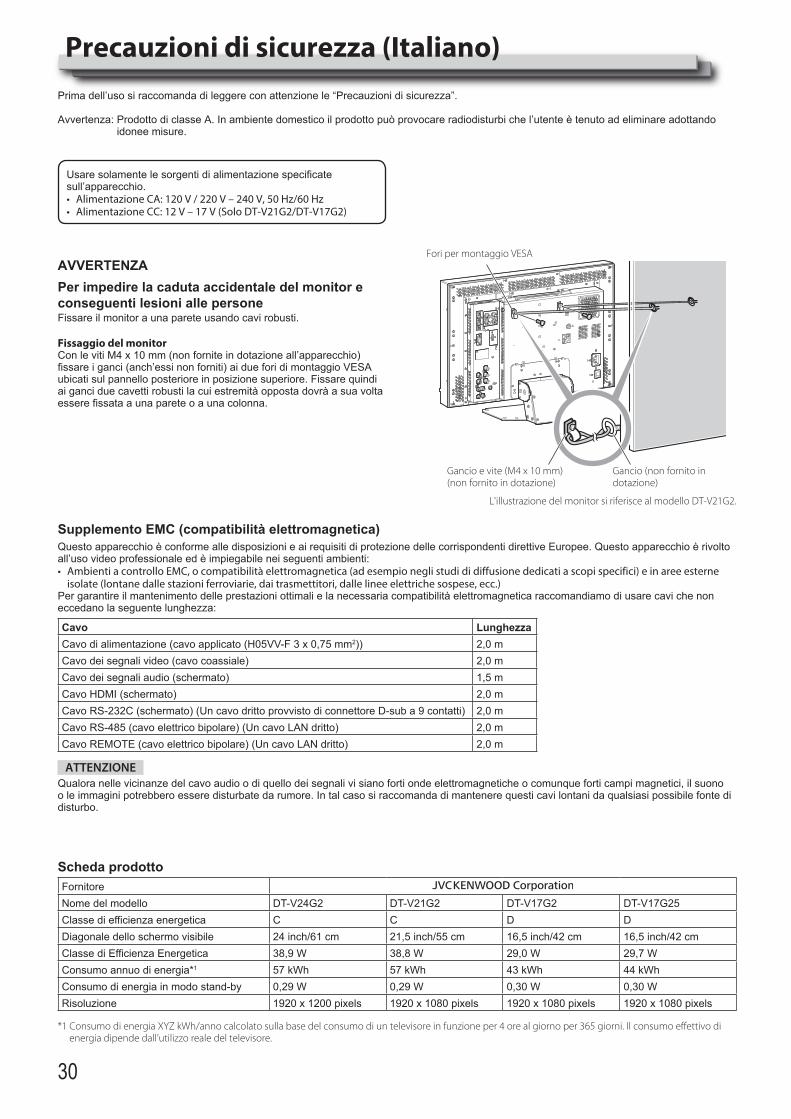
30
Precauzioni di sicurezza (Italiano)Prima dell’uso si raccomanda di leggere con attenzione le “Precauzioni di sicurezza”.
Avvertenza: Prodotto di classe A. In ambiente domestico il prodotto può provocare radiodisturbi che l’utente è tenuto ad eliminare adottando idonee misure.
Usare solamente le sorgenti di alimentazione specificate sull’apparecchio.• Alimentazione CA: 120 V / 220 V – 240 V, 50 Hz/60 Hz• Alimentazione CC: 12 V – 17 V (Solo DT-V21G2/DT-V17G2)
AVVERTENZAPer impedire la caduta accidentale del monitor e conseguenti lesioni alle personeFissare il monitor a una parete usando cavi robusti.
Fissaggio del monitorCon le viti M4 x 10 mm (non fornite in dotazione all’apparecchio) fissare i ganci (anch’essi non forniti) ai due fori di montaggio VESA ubicati sul pannello posteriore in posizione superiore. Fissare quindi ai ganci due cavetti robusti la cui estremità opposta dovrà a sua volta essere fissata a una parete o a una colonna.
Gancio e vite (M4 x 10 mm) (non fornito in dotazione)
Gancio (non fornito in dotazione)
Fori per montaggio VESA
L'illustrazione del monitor si riferisce al modello DT-V21G2.
Supplemento EMC (compatibilità elettromagnetica)Questo apparecchio è conforme alle disposizioni e ai requisiti di protezione delle corrispondenti direttive Europee. Questo apparecchio è rivolto all’uso video professionale ed è impiegabile nei seguenti ambienti:• Ambienti a controllo EMC, o compatibilità elettromagnetica (ad esempio negli studi di diffusione dedicati a scopi specifici) e in aree esterne
isolate (lontane dalle stazioni ferroviarie, dai trasmettitori, dalle linee elettriche sospese, ecc.)Per garantire il mantenimento delle prestazioni ottimali e la necessaria compatibilità elettromagnetica raccomandiamo di usare cavi che non eccedano la seguente lunghezza:
Cavo LunghezzaCavo di alimentazione (cavo applicato (H05VV-F 3 x 0,75 mm2)) 2,0 mCavo dei segnali video (cavo coassiale) 2,0 mCavo dei segnali audio (schermato) 1,5 mCavo HDMI (schermato) 2,0 mCavo RS-232C (schermato) (Un cavo dritto provvisto di connettore D-sub a 9 contatti) 2,0 mCavo RS-485 (cavo elettrico bipolare) (Un cavo LAN dritto) 2,0 mCavo REMOTE (cavo elettrico bipolare) (Un cavo LAN dritto) 2,0 m
ATTENZIONEQualora nelle vicinanze del cavo audio o di quello dei segnali vi siano forti onde elettromagnetiche o comunque forti campi magnetici, il suono o le immagini potrebbero essere disturbate da rumore. In tal caso si raccomanda di mantenere questi cavi lontani da qualsiasi possibile fonte di disturbo.
Scheda prodottoFornitoreNome del modello DT-V24G2 DT-V21G2 DT-V17G2 DT-V17G25Classe di efficienza energetica C C D DDiagonale dello schermo visibile 24 inch/61 cm 21,5 inch/55 cm 16,5 inch/42 cm 16,5 inch/42 cmClasse di Efficienza Energetica 38,9 W 38,8 W 29,0 W 29,7 WConsumo annuo di energia*1 57 kWh 57 kWh 43 kWh 44 kWhConsumo di energia in modo stand-by 0,29 W 0,29 W 0,30 W 0,30 WRisoluzione 1920 x 1200 pixels 1920 x 1080 pixels 1920 x 1080 pixels 1920 x 1080 pixels
*1 Consumo di energia XYZ kWh/anno calcolato sulla base del consumo di un televisore in funzione per 4 ore al giorno per 365 giorni. Il consumo effettivo di energia dipende dall’utilizzo reale del televisore.
DT-V24G2_EN.indb 30 2016/07/27 16:37:27
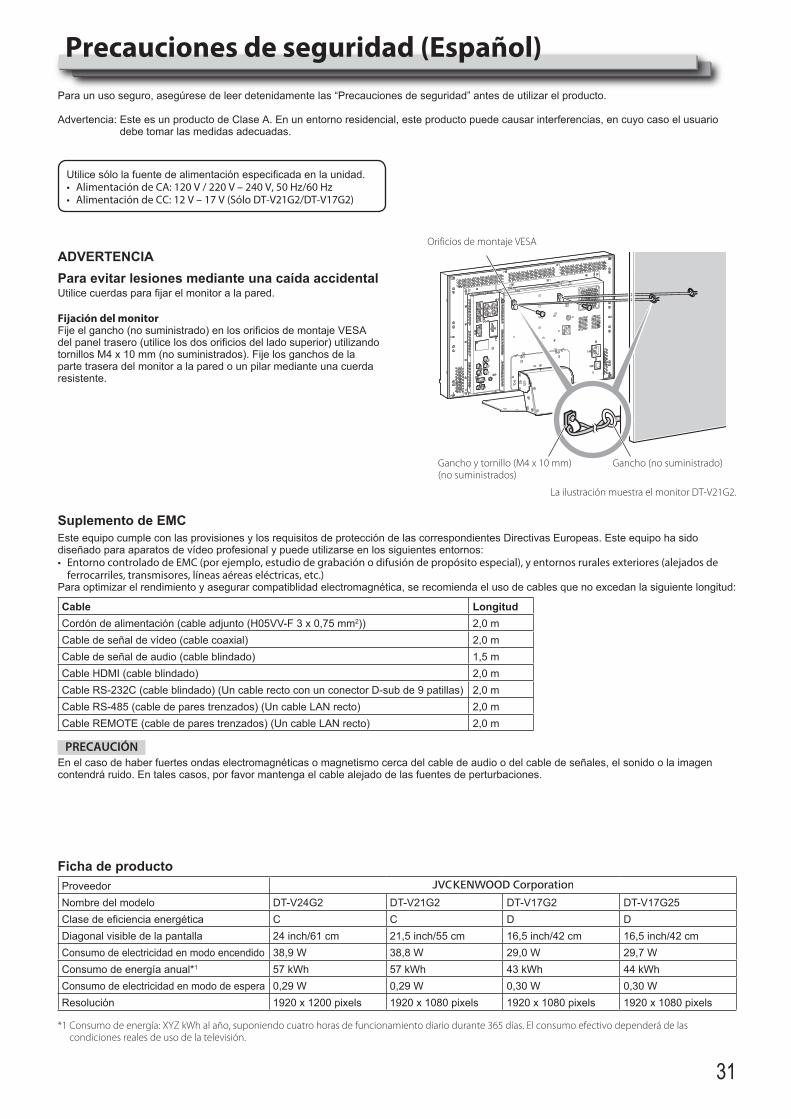
31
Precauciones de seguridad (Español)Para un uso seguro, asegúrese de leer detenidamente las “Precauciones de seguridad” antes de utilizar el producto.
Advertencia: Este es un producto de Clase A. En un entorno residencial, este producto puede causar interferencias, en cuyo caso el usuario debe tomar las medidas adecuadas.
Utilice sólo la fuente de alimentación especificada en la unidad.• Alimentación de CA: 120 V / 220 V – 240 V, 50 Hz/60 Hz• Alimentación de CC: 12 V – 17 V (Sólo DT-V21G2/DT-V17G2)
ADVERTENCIAPara evitar lesiones mediante una caída accidentalUtilice cuerdas para fijar el monitor a la pared.
Fijación del monitorFije el gancho (no suministrado) en los orificios de montaje VESA del panel trasero (utilice los dos orificios del lado superior) utilizando tornillos M4 x 10 mm (no suministrados). Fije los ganchos de la parte trasera del monitor a la pared o un pilar mediante una cuerda resistente.
Gancho y tornillo (M4 x 10 mm) (no suministrados)
Gancho (no suministrado)
Orificios de montaje VESA
La ilustración muestra el monitor DT-V21G2.
Suplemento de EMCEste equipo cumple con las provisiones y los requisitos de protección de las correspondientes Directivas Europeas. Este equipo ha sido diseñado para aparatos de vídeo profesional y puede utilizarse en los siguientes entornos:• Entorno controlado de EMC (por ejemplo, estudio de grabación o difusión de propósito especial), y entornos rurales exteriores (alejados de
ferrocarriles, transmisores, líneas aéreas eléctricas, etc.)Para optimizar el rendimiento y asegurar compatiblidad electromagnética, se recomienda el uso de cables que no excedan la siguiente longitud:
Cable LongitudCordón de alimentación (cable adjunto (H05VV-F 3 x 0,75 mm2)) 2,0 mCable de señal de vídeo (cable coaxial) 2,0 mCable de señal de audio (cable blindado) 1,5 mCable HDMI (cable blindado) 2,0 mCable RS-232C (cable blindado) (Un cable recto con un conector D-sub de 9 patillas) 2,0 mCable RS-485 (cable de pares trenzados) (Un cable LAN recto) 2,0 mCable REMOTE (cable de pares trenzados) (Un cable LAN recto) 2,0 m
PRECAUCIÓNEn el caso de haber fuertes ondas electromagnéticas o magnetismo cerca del cable de audio o del cable de señales, el sonido o la imagen contendrá ruido. En tales casos, por favor mantenga el cable alejado de las fuentes de perturbaciones.
Ficha de productoProveedorNombre del modelo DT-V24G2 DT-V21G2 DT-V17G2 DT-V17G25Clase de eficiencia energética C C D DDiagonal visible de la pantalla 24 inch/61 cm 21,5 inch/55 cm 16,5 inch/42 cm 16,5 inch/42 cmConsumo de electricidad en modo encendido 38,9 W 38,8 W 29,0 W 29,7 WConsumo de energía anual*1 57 kWh 57 kWh 43 kWh 44 kWhConsumo de electricidad en modo de espera 0,29 W 0,29 W 0,30 W 0,30 WResolución 1920 x 1200 pixels 1920 x 1080 pixels 1920 x 1080 pixels 1920 x 1080 pixels
*1 Consumo de energía: XYZ kWh al año, suponiendo cuatro horas de funcionamiento diario durante 365 días. El consumo efectivo dependerá de las condiciones reales de uso de la televisión.
DT-V24G2_EN.indb 31 2016/07/27 16:37:28
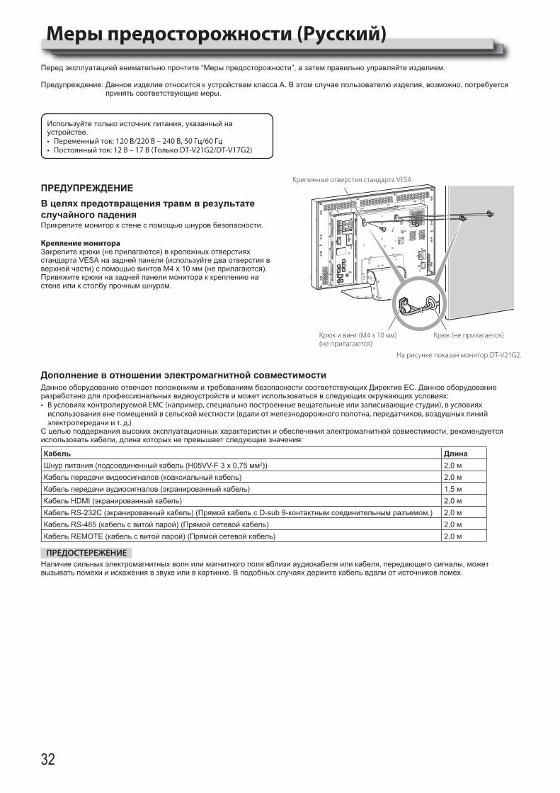
32
Меры предосторожности (Русский)Перед эксплуатацией внимательно прочтите “Меры предосторожности”, а затем правильно управляйте изделием.
Предупреждение: Данное изделие относится к устройствам класса А. В этом случае пользователю изделия, возможно, потребуется принять соответствующие меры.
Используйте только источник питания, указанный на устройстве.• Переменный ток: 120 В/220 В – 240 В, 50 Гц/60 Гц• Постоянный ток: 12 В – 17 В (Только DT-V21G2/DT-V17G2)
ПРЕДУПРЕЖДЕНИЕВ целях предотвращения травм в результате случайного паденияПрикрепите монитор к стене с помощью шнуров безопасности.
Крепление монитораЗакрепите крюки (не прилагаются) в крепежных отверстиях стандарта VESA на задней панели (используйте два отверстия в верхней части) с помощью винтов M4 x 10 мм (не прилагаются). Привяжите крюки на задней панели монитора к креплению на стене или к столбу прочным шнуром.
Крюк и винт (M4 x 10 мм) (не прилагаются)
Крюк (не прилагается)
Крепежные отверстия стандарта VESA
На рисунке показан монитор DT-V21G2.
Дополнение в отношении электромагнитной совместимостиДанное оборудование отвечает положениям и требованиям безопасности соответствующих Директив ЕС. Данное оборудование разработано для профессиональных видеоустройств и может использоваться в следующих окружающих условиях:• В условиях контролируемой EMC (например, специально построенные вещательные или записывающие студии), в условиях
использования вне помещений в сельской местности (вдали от железнодорожного полотна, передатчиков, воздушных линий электропередачи и т. д.)
С целью поддержания высоких эксплуатационных характеристик и обеспечения электромагнитной совместимости, рекомендуется использовать кабели, длина которых не превышает следующие значения:
Кабель ДлинаШнур питания (подсоединенный кабель (H05VV-F 3 x 0,75 мм2)) 2,0 мКабель передачи видеосигналов (коаксиальный кабель) 2,0 мКабель передачи аудиосигналов (экранированный кабель) 1,5 мКабель HDMI (экранированный кабель) 2,0 мКабель RS-232C (экранированный кабель) (Прямой кабель с D-sub 9-контактным соединительным разъемом.) 2,0 мКабель RS-485 (кабель с витой парой) (Прямой сетевой кабель) 2,0 мКабель REMOTE (кабель с витой парой) (Прямой сетевой кабель) 2,0 м
ПРЕДОСТЕРЕЖЕНИЕНаличие сильных электромагнитных волн или магнитного поля вблизи аудиокабеля или кабеля, передающего сигналы, может вызывать помехи и искажения в звуке или в картинке. В подобных случаях держите кабель вдали от источников помех.
DT-V24G2_EN.indb 32 2016/07/27 16:37:29
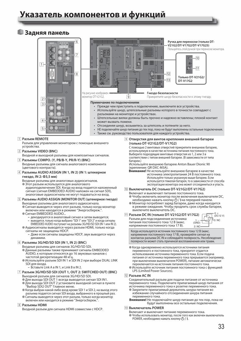
33
Указатель компонентов и функций
1 Разъем REMOTEРазъем для управления монитором с помощью внешнего устройства.
2 Разъемы VIDEO (BNC)Входной и выходной разъемы для композитных сигналов.
3 Разъемы COMPO. (Y, PB/B-Y, PR/R-Y) (BNC)Входные разъемы для сигнала аналогового компонента (цветового контраста).
4 Разъемы AUDIO ASSIGN (IN 1, IN 2) (IN 1: штекерное гнездо, IN 2: Φ3,5 мм)Входные разъемы для аналоговых аудиосигналов.l Этот разъем используется для аналогового
аудиоподключения SDI. Когда на вход подается наложенный сигнал (сигнал EMBEDDED AUDIO наложен на сигнал SDI), аналоговые аудиосигналы не могут подаваться на вход.
5 Разъемы AUDIO ASSIGN (MONITOR OUT) (штекерное гнездо)Выходные разъемы для аналогового аудиосигнала.l Сигнал выводится через этот разъем, только когда монитор
включен или находится в режиме “Энергосбереж.”.l Сигнал EMBEDDED AUDIO...
– декодируется в аналоговый сигнал и затем выводится; – выводится, только когда выбрано “SDI 1” или “SDI 2” и когда сигналы
EMBEDDED AUDIO поступают на разъемы 3G/HD/SD SDI (IN 1 или IN 2).l Аудиосигналы выводятся через разъем HDMI, только когда
сигналы не защищены HDCP. – Даже если сигналы защищены HDCP, звук выводится через динамики.
6 Разъемы 3G/HD/SD SDI (IN 1, IN 2) (BNC)Входные разъемы для сигналов 3G/HD/SD SDI.l Данные разъемы также принимают сигналы EMBEDDED
AUDIO, к которым относятся до 16 звуковых каналов с частотой дискретизации 48 кГц.
l Используйте разъем SDI IN 1 и SDI IN 2 при выборе DUAL LINK SDI для входа.
– Вставьте Link A в IN 1, и Link B в IN 2.7 Разъем 3G/HD/SD SDI (OUT 1, OUT 2: SWITCHED OUT) (BNC)
Выходной разъем для сигналов 3G/HD/SD SDI.l Для выхода SDI OUT 1 всегда выводится сигнал SDI IN1.l Для выхода SDI OUT 2 установите выходной сигнал в пункте
“Выбор SDI2 OUT” Главное меню.l Когда выбран какой-либо вход кроме SDI 1 и SDI 2, на выход этого
разъема подается сигнал SDI входа, выбранного в прошлый раз.l Сигналы выводятся через этот разъем, только когда монитор
включен или находится в режиме “Энергосбереж.”.8 Разъемы HDMI
Входной разъем для сигнала HDMI совместим с HDCP.
Задняя панель
9 Отверстия для винтов крепления внешней батареи (только DT-V21G2/DT-V17G2)С помощью 2 винтовых отверстий прикрепите внешнюю батарею, используемую в качестве источника питания постоянного тока. Выберите подходящие винтовые отверстия из 1, 2 или 3 в соответствии с типом внешней батареи. (В зависимости от типа батареи.) Используйте внешнюю батарею Anton Bauer Dionic 90 (крепление: QR DXC-M3A).Внимание! Не используйте внешнюю батарею в качестве
источника электропитания 24 В постоянного тока. Используйте только указанную выше батарею. Если
используется тяжелая батарея, то в зависимости от способа эксплуатации монитора она может отсоединиться и упасть.
p Выключатель DC (только DT-V21G2/DT-V17G2)Включает и выключает питание постоянного тока.l Чтобы включить монитор после включения выключателя DC,
необходимо нажать кнопку на передней панели.l Монитор потребляет заряд батареи, даже когда находится
в режиме ожидания. Чтобы продлить срок службы батареи, выключите выключатель DC.
q Разъем DC IN (только DT-V21G2/DT-V17G2)Разъем для подсоединения источника питания постоянного тока 12 В (макс. напряжение постоянного тока 17 В).
Когда используется источник постоянного тока 12 В (макс. напряжение постоянного тока 17 В), проверяйте сигнал на контактах разъема DC IN и соблюдайте полярность. Несоблюдение полярности может стать причиной воспламенения или травм.
l Когда одновременно используются источники питания переменного и постоянного тока, приоритет отдается использованию источника переменного тока. Если подача питания от источника переменного тока прерывается (например, при выключении выключателя POWER), питание автоматически переключается на источник питания постоянного тока.
l Используйте источник питания постоянного тока с функцией LPS (Limited Power Sources).
w Разъем AC INСоединительный разъем для подачи питания от источника переменного тока. Подключите прилагаемый шнур питания от источника переменного тока к розетке переменного тока.l Закрепите прилагаемый держатель шнура питания во
избежание случайного отсоединения шнура питания переменного тока.
Внимание! Не подключайте шнур питания до тех пор, пока не будут выполнены все остальные подключения.
e Выключатель POWERВключает и выключает питание переменного тока.l Чтобы использовать монитор, после того как включен выключатель
POWER, необходимо нажать кнопку .
Примечание по подключениям• Преждечемприступитькподключению,выключитевсеустройства.• Используйтешнур,штепсельныеразъемыкотороговточностисовпадаютс
разъемами на мониторе и устройствах.• Штепсельныевилкидолжныбытьпрочноинадежновставлены;плохойконтакт
может вызвать помехи.• Отсоединяяшнур,возьмитесьзаштепсельипотянитезанего.• НЕ подключайте шнур питания до тех пор, пока не будут выполнены остальные подключения.• Такжесм.руководствопользователядлякаждогоустройства.
Ручка для переноски (только DT-V21G2/DT-V17G2/DT-V17G25)Пользуйтесь этой ручкой при переноске монитора.
Только DT-V21G2/ DT-V17G2
Гнездо безопасностиПрикрепите шнур безопасности к этому гнезду.
На рисунке изображен монитор DT-V21G2.
DT-V24G2_EN.indb 33 2016/07/27 16:37:30
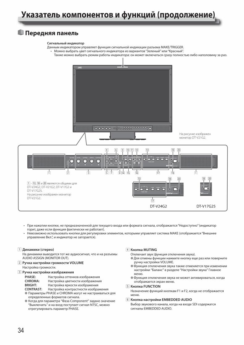
34
Указатель компонентов и функций (продолжение)
На рисунке изображен монитор DT-V21G2.
Передняя панельСигнальный индикаторДанным индикатором управляет функция сигнальной индикации разъема MAKE/TRIGGER.• Можновыбратьцветсигнальногоиндикатораизвариантов“Зеленый”или“Красный”. Также можно выбрать режим работы индикатора: он может включаться сразу полностью либо наполовину за раз.
• Принажатиикнопки,непредназначеннойдлятекущеговходаилиформатасигнала,отображается“Недоступно”(индикаторгорит, даже если функция фактически не работает).
• Невозможноиспользоватькнопкидлярегулировкиэлементов,которымиуправляетсистемаMAKE(отображается“Внешнееуправление Вкл.”, и индикатор не загорается).
1 Динамики (стерео)На динамики выводится тот же аудиосигнал, что и на разъемы AUDIO ASSIGN (MONITOR OUT).
2 Ручка настройки громкости VOLUMEНастройка громкости.
3 Ручка настройки изображенияPHASE: Настройка оттенков изображенияCHROMA: Настройка цветности изображенияBRIGHT: Настройка яркости изображенияCONTRAST: Настройка контрастности изображенияl Параметры PHASE и CHROMA могут не настраиваться для
определенных форматов сигнала.l Когда для параметра “Фаза Component” задано значение
“Выключить” и на вход поступает сигнал NTSC, можно отрегулировать параметр PHASE.
4 Кнопка MUTINGОтключаетзвук(функцияотключениязвука).l Для отмены функции нажмите кнопку еще раз или поверните
ручку настройки VOLUME.l Функция отключения звука также отменяется при изменении
настройки “Баланс” в разделе “Настройки звука” Главное меню.
l Функция отключения звука не может активироваться, когда отображается экран меню.
5 Кнопка FUNCTIONНазначение функций кнопкам F1 и F2, когда не отображается меню.
6 Кнопка настройки EMBEDDED AUDIOВыбор звукового канала, когда на входе SDI содержатся сигналы EMBEDDED AUDIO.
DT-V24G2 DT-V17G25
1 - e, i и ; являются общими для DT-V24G2, DT-V21G2, DT-V17G2 и DT-V17G25.На рисунке изображен монитор DT-V21G2.
DT-V24G2_EN.indb 34 2016/07/27 16:37:32
35
7 Кнопки / / / Когда отображается экран меню, позволяют выбрать или настроить элементы меню.l Нажатие кнопки при нажатой кнопке выводит на экран
Меню настроек.8 Кнопка MENU
Включает/выключает отображение Главное меню.9 Кнопка/индикатор COLOR OFF
Отображаеттолькосигналяркости.l Эта функция не работает для входных сигналов RGB.
p Кнопка/индикатор SCOPEОтображает/скрываетиндикациюформысигналаивектроскопа.l Каждый раз при нажатии этой кнопки окно меняется в
следующем порядке.
ГистограммаИндикация формы сигнала
ВектроскопНе отображается
q Кнопка/индикатор AREA MARKERОтображает/скрываетмаркеробласти.l Стиль маркера области можно выбрать в разделе “Маркер”
Главное меню.l Эта функция работает только при выводе изображения в
формате 16:9.l Эта функция не работает, когда для параметра “Маркер
области” или “Маркер области - R” установлено значение “Выкл.” в поле “Маркер”.
w Кнопка/индикатор SAFETY MARKERОтображает/скрываетмаркербезопасности.lОбластьмаркерабезопасностиможнонастроитьвразделе
“Маркер” Главное меню.l Эта функция не будет работать, когда изображение
выводится в формате 1:1 и для параметра “Размер SD4:3” в меню установлено значение “Полноразмерный”.
l Эта функция не работает, когда для параметра “Маркер безопасности” или “Маркер безопасности - R” установлено значение “Выкл.” в поле “Маркер”.
e Кнопка/индикатор 1:1Выводит изображение с изначальным разрешением входного сигнала.l Форматное соотношение изображения зависит от входного
сигнала.r Кнопка/индикатор SCREENS CHECK
Выводит на экран только выбранный элемент (R, G или B) видеосигнала.l Эта функция не работает для входных сигналов RGB.l При каждом нажатии этой кнопки изображение меняется в
следующем порядке.RGB (нормальный экран) Красный экран
Синий экран Зеленый экран
t Кнопка/индикатор T.C. (временной код)Включает/выключает отображение данных времени (временной код), содержащихся в сигнале SDI.l Тип временного кода можно выбрать в разделе
“Информация” Меню настроек.y Кнопки/индикаторы F1/F2
Можно использовать функции, назначенные этой кнопке.
u Кнопки/индикаторы INPUT SELECTВыбор входа.
SDI 1: Вход с разъема 3G/HD/SD SDI (IN 1)SDI 2: Вход с разъема 3G/HD/SD SDI (IN 2)DUAL LINK: Вход с разъемов 3G/HD/SD SDI (IN 1, IN 2)HDMI: Вход с разъема HDMICOMPO.: Вход с разъемов COMPO.VIDEO: Вход с разъема VIDEO
l Загорается индикатор для выбранного входа.i Индикатор питания
Индикатор не светится: Монитор полностью отключен (выключен выключатель питания на задней панели) или находится в режиме низкого энергопотребления
Индикатор светится зеленым: Монитор включенИндикатор светится оранжевым: Монитор отключен (в
режиме ожидания)Индикатор мигает оранжевым: Монитор в режиме
“Энергосбереж.” (энергосбережения).
o Индикатор DC (только DT-V21G2/DT-V17G2)Когда напряжение источника питания постоянного тока понижается из-за расхода заряда батареи, индикатор изменяет цвет с зеленого на оранжевый. Когда напряжение падает ниже определенного уровня, монитор автоматически отключается и индикатор становится красным.l Перед заменой батареи обязательно выключите
выключатель POWER и выключатель DC на задней панели.l Продолжительность времени, когда индикатор светится
оранжевым, определяется типом и состоянием используемой батареи. Когда индикатор начинается светиться оранжевым, батарею рекомендуется заменить.
; Кнопка Включает и выключает питание (переключает монитор в режим ожидания).l Для полного выключения монитора, выключите
выключатель POWER и выключатель DC.
DT-V24G2_EN.indb 35 2016/07/27 16:37:32
© 2016 JVC KENWOOD Corporation B5A-1245-00
MU
LTI FOR
MAT LC
D M
ON
ITOR
D
T-V24G2 / D
T-V21G2 / D
T-V17G2 / D
T-V17G25
DT-V24G2_EN.indb 36 2016/07/27 16:37:32