failure analysis of coal pulverizer mill shaft
TRANSCRIPT
Failure analysis of coal pulverizer mill shaft
N. Parida*, S. Tarafder, S.K. Das, P. Kumar,G. Das, V.R. Ranganath, D.K. Bhattacharya
National Metallurgical Laboratory, Jamshedpur, 831007, India
Received 2 October 2002; accepted 14 October 2002
Abstract
Failure of a ball and race type coal pulverizer mill shaft has been analysed. It was found that the shaft, made ofEN 25 steel, failed by fatigue. The fatigue cracks originated from the keyway area, unusually from the top edge. The
presence of elongated manganese sulphide inclusions due to improper heat treatment had reduced the ductility andCVN toughness of the material, and thus made the material more prone to failure.# 2003 Elsevier Ltd. All rights reserved.
Keywords: Shafts; Stress concentrations; Non-destructive inspection; Heat treatment; Fatigue failure
1. Introduction
Shafts used for transmitting power to rotating components are generally subjected to torsional loads. Inaddition, depending upon the mode of attachment of the shaft to the component, they may also experiencetension, compression or bending loads. One of the most common mechanisms through which shafts sub-jected to the above types of load may fail is fatigue. Such fatigue failures are usually the manifestation ofthe ‘‘weakest link’’ phenomenon in which failure initiates at the most vulnerable point in a dynamicallystressed system, often at mechanical or metallurgical stress raisers. Mechanical stress raisers are non-uni-formities in the shape of the shaft such as step changes in diameter, integral collars, holes, abrupt corners,keyways, grooves, threads, splines, press fitted or shrink-fitted attachments and surface discontinuities likeseams, nicks, notches and machining marks. Metallurgical stress raisers include forging laps, quenchcracks, non-metallic inclusions, brittle second-phase particles, corrosion pits etc. The microstructure of theshaft material plays a vital role not only in the initiation of fatigue failures but also during the progressivegrowth of the fatigue crack to cause failure of the component.This paper presents a case of failure of shafts of coal pulverizer mills attached to the boiler of an electricity
generating thermal power plant. These shafts with a recommended life of 100,000 h of operation were failingin typically 8000 h by fatigue. They belonged to the same batch of supply from the same manufacturer, and itwas imperative that it be established if the failures were due to operational reasons or the manufacturing
1350-6307/03/$ - see front matter # 2003 Elsevier Ltd. All rights reserved.
PI I : S1350-6307(02 )00070-5
Engineering Failure Analysis 10 (2003) 733–744
www.elsevier.com/locate/engfailanal
* Corresponding author. Tel.: +91-657-2271709; fax: +91-657-2270527.
E-mail address: [email protected] (N. Parida).
process. The paper describes the failures that were taking place, and details the investigations that werecarried out to understand and analyse them.
2. Background details
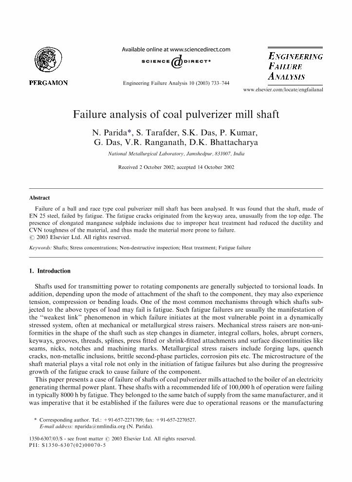
Coal pulverizer mills are employed to break down (pulverize) lumpy coal to fines (typically 200 meshsize) for accelerating combustion by exposing a large surface area to the action of oxygen. They may beclassified into three types: contact, ball and impact mills. The failed shafts of the case under discussion werefrom contact type coal pulverizer mills. Contact mills consist of stationary and power driven elements,which are arranged to provide rolling action with respect to each other. Coal is made to pass between theelements repeatedly until it has been pulverized to the desired fineness. The grinding elements in a contactmill may consist of balls rolling in a race or rollers running over a surface. The failed shafts of the presentcase belong to a ball and race type pulverizer mill. A schematic diagram of such a shaft is shown in Fig. 1,giving details of the geometry of the shaft. The shafts were 72 inches in length with maximum diameter of10 inches, mounted vertically, and supported by four bearings. The maximum speed at which the shaftsrotated was �60 rpm. The direction of rotation was reversed periodically to prevent build up of fines in thecrushing zone.The fabrication of the shafts consisted of hot forging (with a ratio of 4:1 from cast to bloom followed by
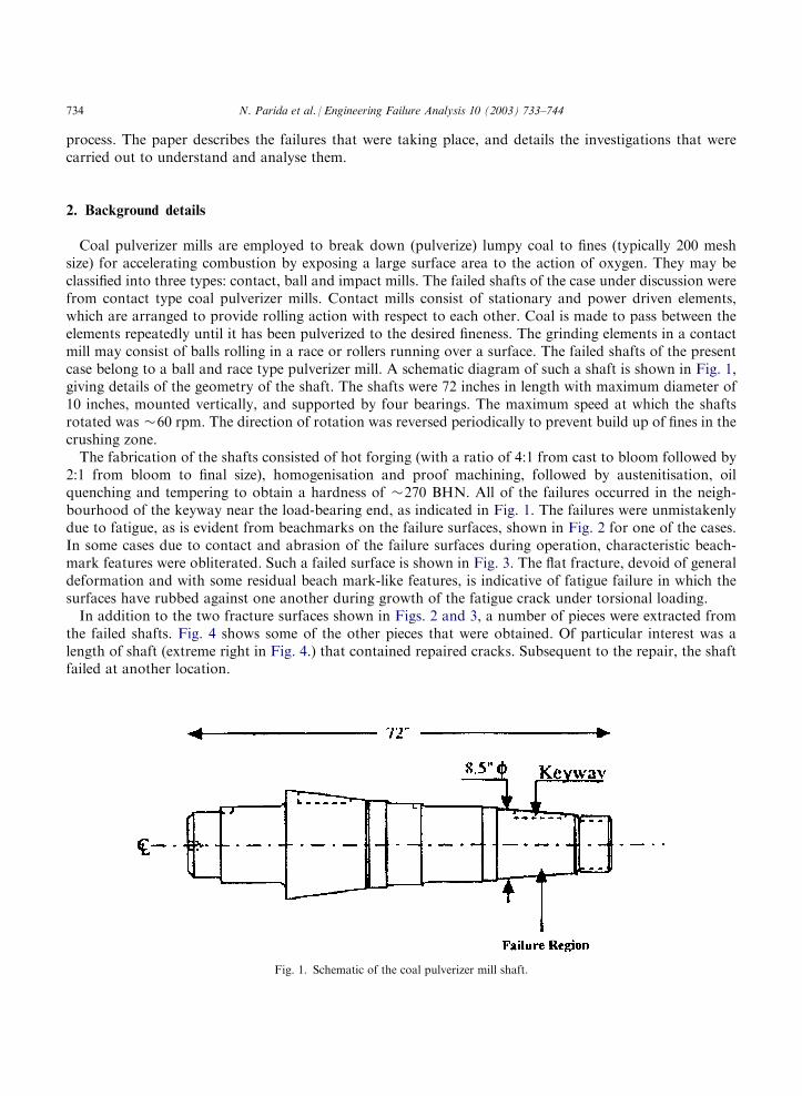
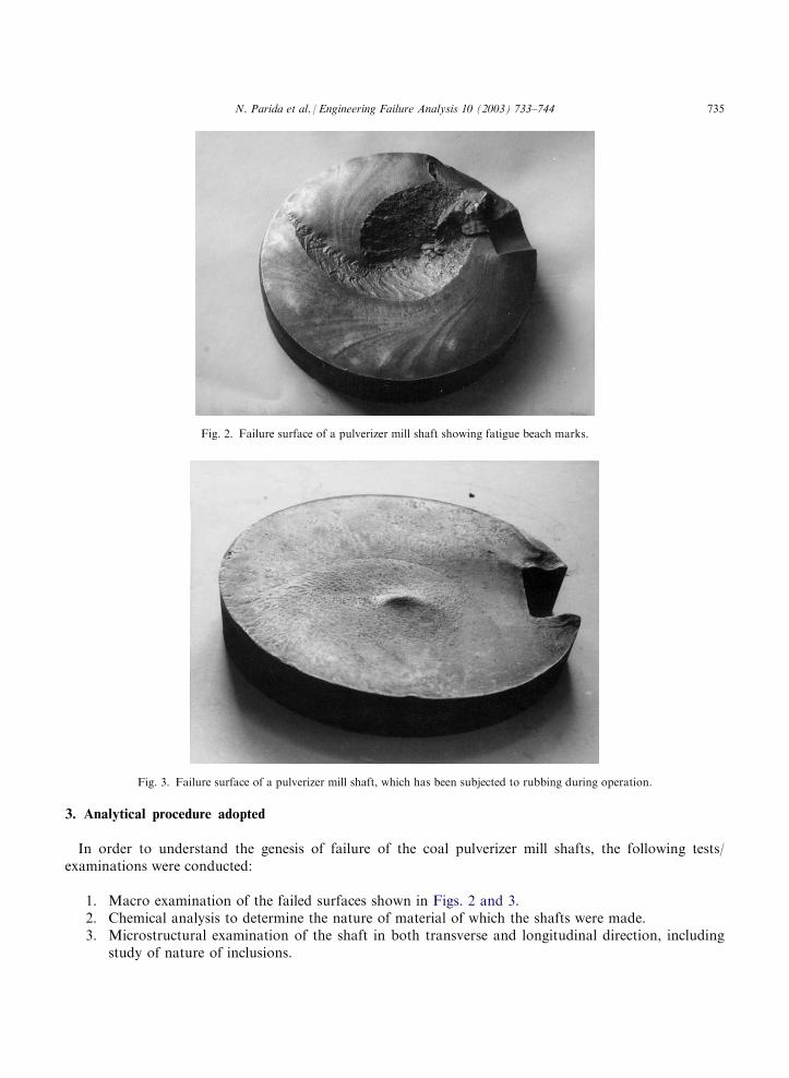
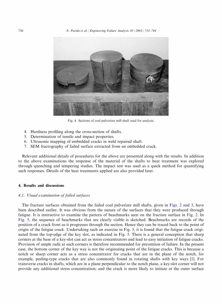
2:1 from bloom to final size), homogenisation and proof machining, followed by austenitisation, oilquenching and tempering to obtain a hardness of �270 BHN. All of the failures occurred in the neigh-bourhood of the keyway near the load-bearing end, as indicated in Fig. 1. The failures were unmistakenlydue to fatigue, as is evident from beachmarks on the failure surfaces, shown in Fig. 2 for one of the cases.In some cases due to contact and abrasion of the failure surfaces during operation, characteristic beach-mark features were obliterated. Such a failed surface is shown in Fig. 3. The flat fracture, devoid of generaldeformation and with some residual beach mark-like features, is indicative of fatigue failure in which thesurfaces have rubbed against one another during growth of the fatigue crack under torsional loading.In addition to the two fracture surfaces shown in Figs. 2 and 3, a number of pieces were extracted from
the failed shafts. Fig. 4 shows some of the other pieces that were obtained. Of particular interest was alength of shaft (extreme right in Fig. 4.) that contained repaired cracks. Subsequent to the repair, the shaftfailed at another location.
Fig. 1. Schematic of the coal pulverizer mill shaft.
734 N. Parida et al. / Engineering Failure Analysis 10 (2003) 733–744
3. Analytical procedure adopted
In order to understand the genesis of failure of the coal pulverizer mill shafts, the following tests/examinations were conducted:
1. Macro examination of the failed surfaces shown in Figs. 2 and 3.
2. Chemical analysis to determine the nature of material of which the shafts were made. 3. Microstructural examination of the shaft in both transverse and longitudinal direction, includingstudy of nature of inclusions.
Fig. 2. Failure surface of a pulverizer mill shaft showing fatigue beach marks.
Fig. 3. Failure surface of a pulverizer mill shaft, which has been subjected to rubbing during operation.
N. Parida et al. / Engineering Failure Analysis 10 (2003) 733–744 735
4. Hardness profiling along the cross-section of shafts.
5. Determination of tensile and impact properties. 6. Ultrasonic mapping of embedded cracks in weld repaired shaft. 7. SEM fractography of failed surface extracted from an embedded crack.Relevant additional details of procedures for the above are presented along with the results. In additionto the above examinations the response of the material of the shafts to heat treatment was exploredthrough quenching and tempering studies. The impact test was used as a quick method for quantifyingsuch responses. Details of the heat treatments applied are also provided later.
4. Results and discussions
4.1. Visual examination of failed surfaces
The fracture surfaces obtained from the failed coal pulverizer mill shafts, given in Figs. 2 and 3, havebeen described earlier. It was obvious from the nature of the surfaces that they were produced throughfatigue. It is instructive to examine the pattern of beachmarks seen on the fracture surface in Fig. 2. InFig. 5, the sequence of beachmarks that are clearly visible is sketched. Beachmarks are records of theposition of a crack front as it progresses through the section. Hence they can be traced back to the point oforigin of the fatigue crack. Undertaking such an exercise in Fig. 5, it is found that the fatigue crack origi-nated from the top-edge of the key slot, as indicated in Fig. 5. There is a general conception that sharpcorners at the base of a key-slot can act as stress concentrators and lead to easy initiation of fatigue cracks.Provision of ample radii at such corners is therefore recommended for prevention of failure. In the presentcase, the bottom corner of the key way is not the originating point of the fatigue cracks. This is because anotch or sharp corner acts as a stress concentrator for cracks that are in the plane of the notch, forexample, peeling-type cracks that are also commonly found in rotating shafts with key ways [1]. Fortransverse cracks in shafts, which are in a plane perpendicular to the notch plane, a key-slot corner will notprovide any additional stress concentration; and the crack is more likely to initiate at the outer surface
Fig. 4. Sections of coal pulverizer mill shaft used for analysis.
736 N. Parida et al. / Engineering Failure Analysis 10 (2003) 733–744
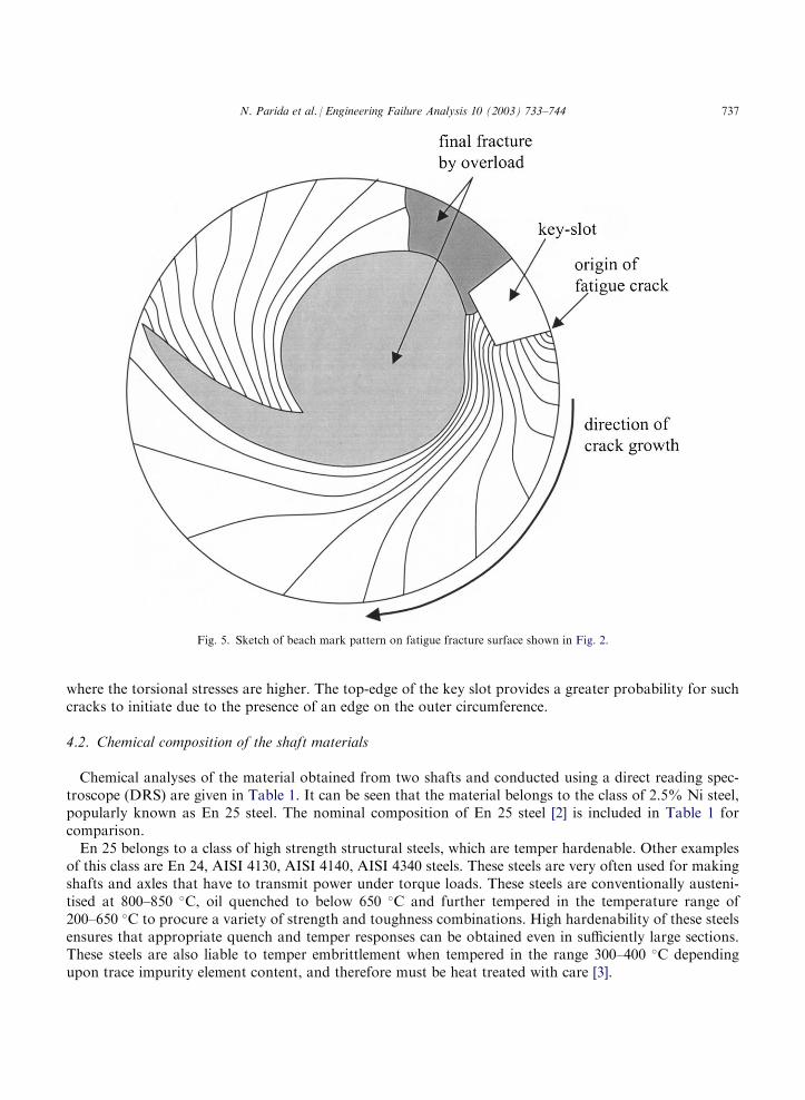
where the torsional stresses are higher. The top-edge of the key slot provides a greater probability for suchcracks to initiate due to the presence of an edge on the outer circumference.
4.2. Chemical composition of the shaft materials
Chemical analyses of the material obtained from two shafts and conducted using a direct reading spec-troscope (DRS) are given in Table 1. It can be seen that the material belongs to the class of 2.5% Ni steel,popularly known as En 25 steel. The nominal composition of En 25 steel [2] is included in Table 1 forcomparison.En 25 belongs to a class of high strength structural steels, which are temper hardenable. Other examples
of this class are En 24, AISI 4130, AISI 4140, AISI 4340 steels. These steels are very often used for makingshafts and axles that have to transmit power under torque loads. These steels are conventionally austeni-tised at 800–850 �C, oil quenched to below 650 �C and further tempered in the temperature range of200–650 �C to procure a variety of strength and toughness combinations. High hardenability of these steelsensures that appropriate quench and temper responses can be obtained even in sufficiently large sections.These steels are also liable to temper embrittlement when tempered in the range 300–400 �C dependingupon trace impurity element content, and therefore must be heat treated with care [3].
Fig. 5. Sketch of beach mark pattern on fatigue fracture surface shown in Fig. 2.
N. Parida et al. / Engineering Failure Analysis 10 (2003) 733–744 737
4.3. Microstructural examination of the shaft material
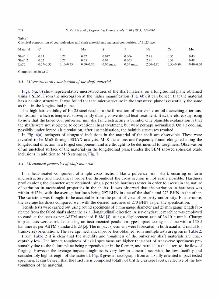
Figs. 6(a, b) show representative microstructures of the shaft material on a longitudinal plane obtainedusing a SEM. From the micrograph at the higher magnification (Fig. 6b), it can be seen that the materialhas a bainitic structure. It was found that the microstructure in the transverse plane is essentially the sameas that in the longitudinal plane.The high hardenability of En 25 steel results in the formation of martensite on oil quenching after aus-
tenitisation, which is tempered subsequently during conventional heat treatment. It is, therefore, surprisingto note that the failed coal pulverizer mill shaft microstructure is bainitic. One plausible explanation is thatthe shafts were not subjected to conventional heat treatment, but were perhaps normalised. On air cooling,possibily under forced air circulation, after austenitisation, the bainitic structures resulted.In Fig. 6(a), stringers of elongated inclusions in the material of the shaft are observable. These were
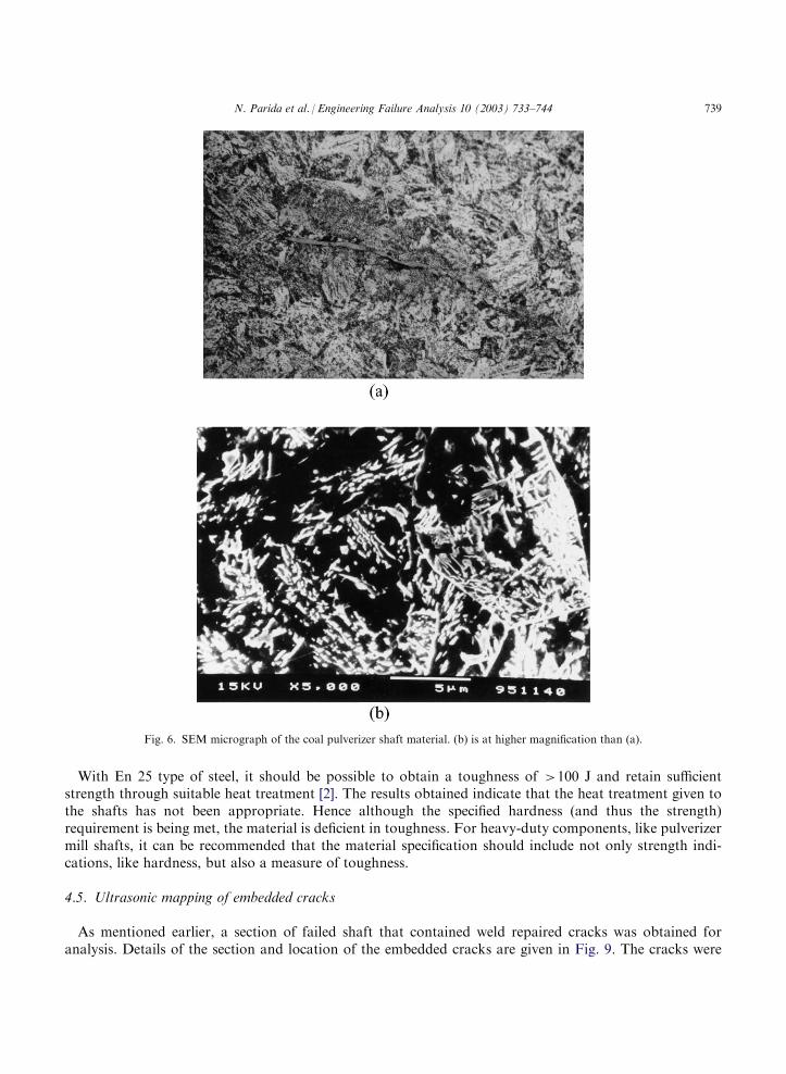
revealed to be MnS through EDAX analysis. MnS inclusions are frequently found elongated along thelongitudinal direction in a forged component, and are thought to be detrimental to toughness. Observationof an unetched surface of the material (in the longitudinal plane) under the SEM showed spherical oxideinclusions in addition to MnS stringers, Fig. 7.
4.4. Mechanical properties of shaft material
In a heat-treated component of ample cross section, like a pulverizer mill shaft, ensuring uniformmicrostructure and mechanical properties throughout the cross section is not easily possible. Hardnessprofiles along the diameter were obtained using a portable hardness tester in order to ascertain the natureof variation in mechanical properties in the shafts. It was observed that the variation in hardness waswithin �12%, with the average hardness being 297 BHN in one of the shafts and 273 BHN in the other.The variation was thought to be acceptable from the point of view of property uniformity. Furthermore,the average hardness compared well with the desired hardness of 270 BHN as per the specification.Tensile tests were carried out using round specimens of 5 mm gauge diameter and 25 mm gauge length fab-
ricated from the failed shafts along the axial (longitudinal) direction. A servohydraulic machine was employedto conduct the tests as per ASTM standard E 8M [4], using a displacement rate of 3�10�3 mm/s. Charpyimpact tests were carried out using an instrumented pendulum type impact testing machine with a 150 Jhammer as per ASTM standard E 23 [5]. The impact specimens were fabricated in both axial and radial (ortransverse) orientations. The average mechanical properties obtained frommultiple tests are given in Table 2.From Table 2 it is clear that the ductility and toughness of the pulverizer shaft materials are unac-
ceptably low. The impact toughness of axial specimens are higher than that of transverse specimens pre-sumably due to the failure plane being perpendicular in the former, and parallel in the latter, to the flow offorging. However the average impact toughness is very low in concordance with the low ductility andconsiderably high strength of the material. Fig. 8 gives a fractograph from an axially oriented impact testedspecimen. It can be seen that the fracture is composed totally of brittle cleavage facets, reflective of the lowtoughness of the material.
Table 1
Chemical composition of coal pulverizer mill shaft material and material composition of En25 steel.
Material
C Si Mn S P Ni Cr MoShaft 1
0.33 0.27 0.57 0.017 0.006 2.45 0.55 0.45Shaft 2
0.32 0.27 0.55 0.02 0.005 2.41 0.57 0.48En25
0.27–0.35 0.10–0.35 0.50–0.70 0.05 max. 0.05 max. 2.30–2.80 0.50–0.80 0.40–0.70Compositions in wt%.
738 N. Parida et al. / Engineering Failure Analysis 10 (2003) 733–744
With En 25 type of steel, it should be possible to obtain a toughness of >100 J and retain sufficientstrength through suitable heat treatment [2]. The results obtained indicate that the heat treatment given tothe shafts has not been appropriate. Hence although the specified hardness (and thus the strength)requirement is being met, the material is deficient in toughness. For heavy-duty components, like pulverizermill shafts, it can be recommended that the material specification should include not only strength indi-cations, like hardness, but also a measure of toughness.
4.5. Ultrasonic mapping of embedded cracks
As mentioned earlier, a section of failed shaft that contained weld repaired cracks was obtained foranalysis. Details of the section and location of the embedded cracks are given in Fig. 9. The cracks were
Fig. 6. SEM micrograph of the coal pulverizer shaft material. (b) is at higher magnification than (a).
N. Parida et al. / Engineering Failure Analysis 10 (2003) 733–744 739
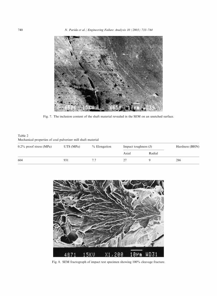
Table 2
Mechanical properties of coal pulverizer mill shaft material
0.2% proof stress (MPa)
UTS (MPa) % Elongation Impact toughness (J) Hardness (BHN)Axial
Radial604
931 7.7 27 9 286Fig. 7. The inclusion content of the shaft material revealed in the SEM on an unetched surface.
Fig. 8. SEM fractograph of impact test specimen showing 100% cleavage fracture.
740 N. Parida et al. / Engineering Failure Analysis 10 (2003) 733–744
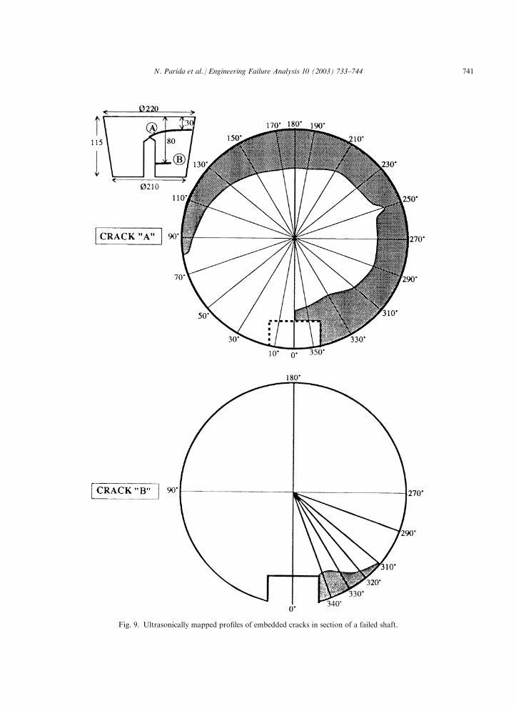
Fig. 9. Ultrasonically mapped profiles of embedded cracks in section of a failed shaft.
N. Parida et al. / Engineering Failure Analysis 10 (2003) 733–744 741
observed during visual inspection on the surface of the shaft while it was in service. To prevent them fromgrowing further, the traces of the cracks on the cylindrical surface were gouged out and the groove formedfilled with chemically matched weld metal. The shaft was then put back into service and it failed subse-quently at another location that was not accessible to in service inspection. In order to ascertain the efficacyof the weld repairing technique, it was decided to inspect the section ultrasonically and verify if cracks hadre-initiated and grown from their original traces.A 6 mm diameter, 1 MHz normal ultrasonic probe was used for ultrasonic inspection using standard
equipment. On the transverse section nearest to the crack being studied, radial lines at regular intervalswere drawn, taking the radial position over the centreline of the keyway as the reference. The ultrasonicprobe was moved on the transverse surface along each of the radial lines, and the position of the crackfront determined from the reflection of the ultrasonic signal. The crack profiles obtained for the two cracksby this method are shown in Fig. 9.It is clear from Fig. 9 that cracks have extended into the shaft up to substantial depths in spite of the
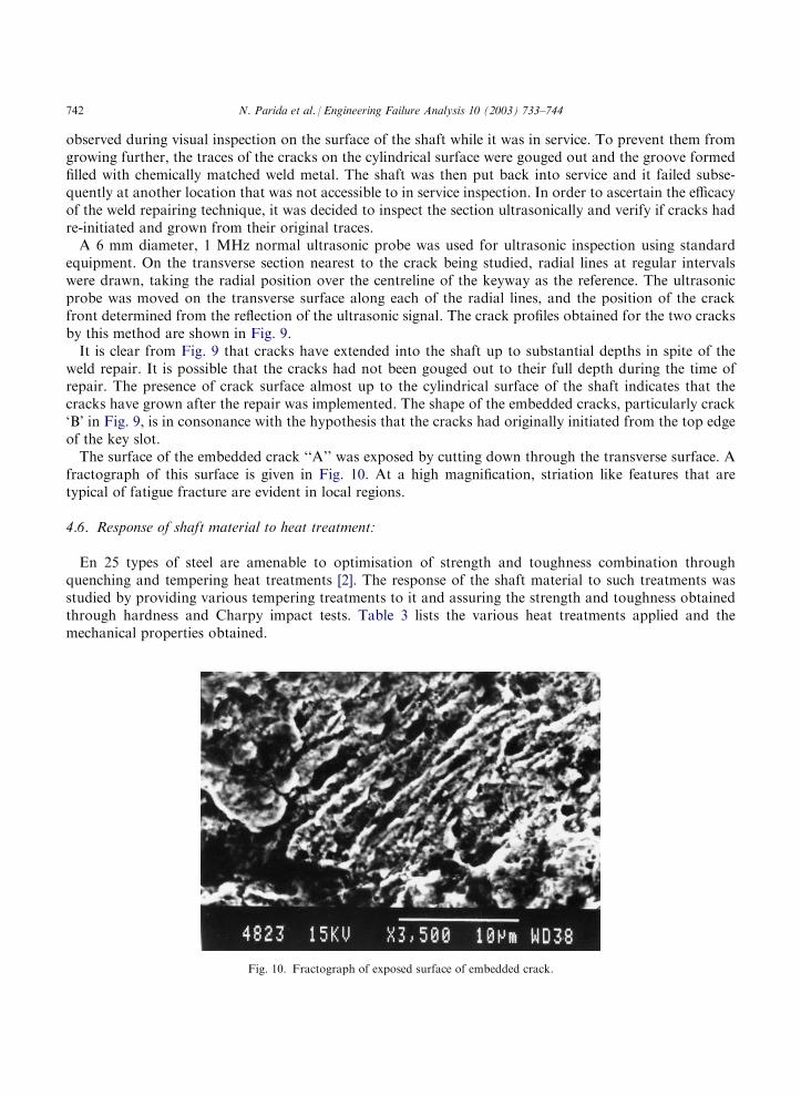
weld repair. It is possible that the cracks had not been gouged out to their full depth during the time ofrepair. The presence of crack surface almost up to the cylindrical surface of the shaft indicates that thecracks have grown after the repair was implemented. The shape of the embedded cracks, particularly crack‘B’ in Fig. 9, is in consonance with the hypothesis that the cracks had originally initiated from the top edgeof the key slot.The surface of the embedded crack ‘‘A’’ was exposed by cutting down through the transverse surface. A
fractograph of this surface is given in Fig. 10. At a high magnification, striation like features that aretypical of fatigue fracture are evident in local regions.
4.6. Response of shaft material to heat treatment:
En 25 types of steel are amenable to optimisation of strength and toughness combination throughquenching and tempering heat treatments [2]. The response of the shaft material to such treatments wasstudied by providing various tempering treatments to it and assuring the strength and toughness obtainedthrough hardness and Charpy impact tests. Table 3 lists the various heat treatments applied and themechanical properties obtained.
Fig. 10. Fractograph of exposed surface of embedded crack.
742 N. Parida et al. / Engineering Failure Analysis 10 (2003) 733–744
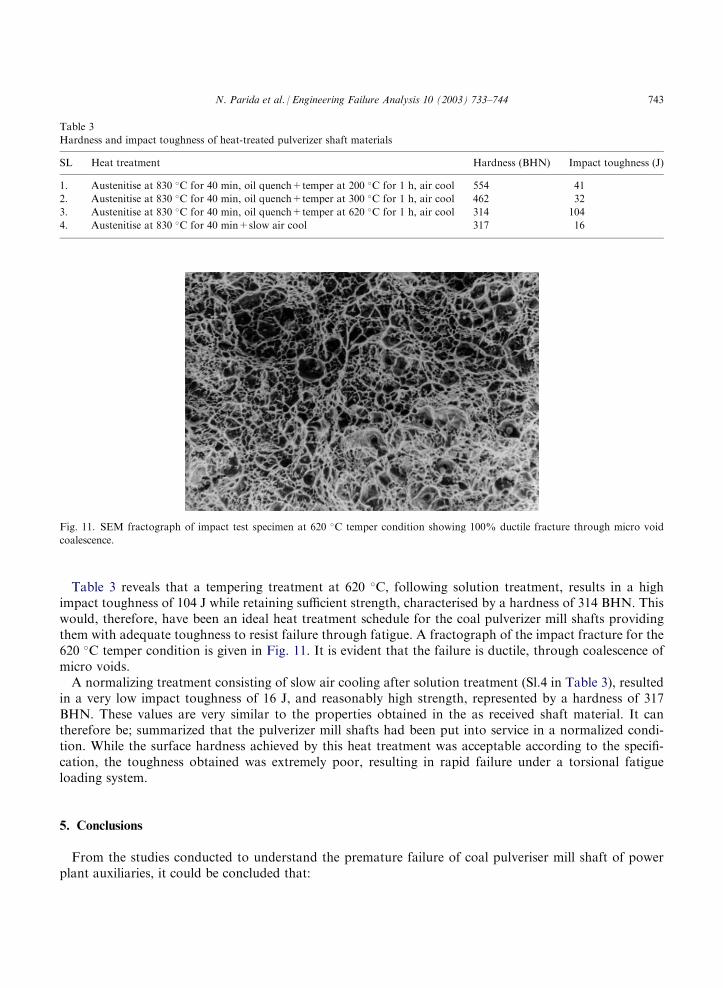
Table 3 reveals that a tempering treatment at 620 �C, following solution treatment, results in a highimpact toughness of 104 J while retaining sufficient strength, characterised by a hardness of 314 BHN. Thiswould, therefore, have been an ideal heat treatment schedule for the coal pulverizer mill shafts providingthem with adequate toughness to resist failure through fatigue. A fractograph of the impact fracture for the620 �C temper condition is given in Fig. 11. It is evident that the failure is ductile, through coalescence ofmicro voids.A normalizing treatment consisting of slow air cooling after solution treatment (Sl.4 in Table 3), resulted
in a very low impact toughness of 16 J, and reasonably high strength, represented by a hardness of 317BHN. These values are very similar to the properties obtained in the as received shaft material. It cantherefore be; summarized that the pulverizer mill shafts had been put into service in a normalized condi-tion. While the surface hardness achieved by this heat treatment was acceptable according to the specifi-cation, the toughness obtained was extremely poor, resulting in rapid failure under a torsional fatigueloading system.
5. Conclusions
From the studies conducted to understand the premature failure of coal pulveriser mill shaft of powerplant auxiliaries, it could be concluded that:
Table 3
Hardness and impact toughness of heat-treated pulverizer shaft materials
SL
Heat treatment Hardness (BHN) Impact toughness (J)1.
Austenitise at 830 �C for 40 min, oil quench+temper at 200 �C for 1 h, air cool 554 412.
Austenitise at 830 �C for 40 min, oil quench+temper at 300 �C for 1 h, air cool 462 323.
Austenitise at 830 �C for 40 min, oil quench+temper at 620 �C for 1 h, air cool 314 1044.
Austenitise at 830 �C for 40 min+slow air cool 317 16Fig. 11. SEM fractograph of impact test specimen at 620 �C temper condition showing 100% ductile fracture through micro void
coalescence.
N. Parida et al. / Engineering Failure Analysis 10 (2003) 733–744 743
1. The failures were due to fatigue crack extension under reversed torsional loading.
2. The fatigue cracks originated mainly at the top edge of the key slot. 3. Initiation and growth of the cracks was facilitated by the brittle microstructures of low toughnessresulting from improper heat treatment.4. Weld repairing of cracks formed during service may not be very effective in restoring the condition
of heavy-duty shafts.
It is recommended that the material specification of components like coal pulverizer mill shafts shouldconsist of not only a minimum strength criterion like hardness, but must include a toughness parameteralso. Forgings submitted for heat treatment may provide allowances for coupons to be extracted fromwhich impact specimens may be fabricated and tested.
Acknowledgements
The authors wish to thank Professor S.P. Mehrotra, Director, National Metallurgical Laboratory,Jamshedpur for his kind permission to publish the results.
References
[1] ASM Metals Handbook. Failure analysis and preventation. Metals Park (OH): American Society for Metals; 1986.
[2] Woolman J, Mottrum RA. The mechanical and physical properties of British standard EN steels. Oxford: Pergamon Press; 1966.
[3] Briant CL, Banerji SK. Treatise on Materials Science and Technology 1983;25:21–58.
[4] ASTM E8M. Standard test method for tension testing of metallic materials. Annual Book of ASTM Standards, vol. 3.01. 1998.
p. 78–98.
[5] ASTM E23. Standard test methods for notched bar impact testing of metallic materials, vol. 3.01. 1998. p. 138–57.
744 N. Parida et al. / Engineering Failure Analysis 10 (2003) 733–744