underground coal gasification
TRANSCRIPT
Underground Coal Gasifcation: A new clean coal Technology
Shashank Pandey, Shricharan Arumugam and Rehan Arif Khan
Applied Petroleum Engineering - Upstream
University of Petroleum & Energy Studies
Dehradun, India.
Abstract— According to The International Energy Outlook
2013, the world energy consumption will grow by 56 percent
between 2010 to 2040. There is an urgent need to identify
alternative methods of extraction of energy from existing sources.
Underground Coal Gasification (UCG) is a clean coal technology
option suitable for the need of the hour .UCG is a technique to
gasify coal in-situ within the coal seam via a matrix of wells. Coal
is ignited using the rock mass as reactor while injecting steam
and gasifying agent which carries out the chemical reaction
whose end product is Syngas which is a mixture of methane,
carbon monoxide, hydrogen and carbon dioxide. It has been
stated that there are two methods of underground coal
gasification- the shaft method and the borehole method. It’ll be
able to provide cheap energy for the masses hence UCG is one
such source of energy which can immensely boost Energy
security of a nation. Syngas is readily useable fuel for thermal
power plants hence the technology does not require additional
specific infrastructure eventually making it economically
sustainable. This is a breakthrough technology as it provides an
efficient and reliable method to harness the unminable coal
resources. Since UCG operates on coal it is only apt to compare
its environmental performance with coal combustion and on that
parameter UCG stands out as a revolutionary technology because
its emission levels are closest to natural gas (the cleanest fossil
fuel known till date) however underground aquifer
contamination issues have been reported, which can be mitigated
by negative hydraulic gradient. There is a possible conflict with
Coal Bed Methane (CBM) developers but the technology has
enough scope in the future that it’ll carve out an independent
niche for itself.
Keywords—UCG; Syngas; Energy Security; aquifer; hydraulic
gradient; CBM
I. INTRODUCTION
About 100-400 million years ago trees and plants in huge swamp areas got buried deep below the earth and got converted into a carbonaceous substance which evolved to be the prime energy source for the modern world and came to be known as “Coal”.It has been used as a source of energy for nearly 3000years though it did not become the most sought after energy source until the beginning of the industrial revolution in 18
th century.
Although coal has been extensively been used and is still holds an important position in the world, it poses serious
environmental challenges. Mainly due to organic sulphur, a substance that is chemically bound to coal. Sulphur and nitrogen oxides produced as a result of combustion of coal are prime pollutants. Therefore clean coal technologies have been an area of interest from quite some time. Coal gasification is one such clean coal technology that bypasses conventional coal combustion process thus removing pollutants like SOx, NOx, particulates etc. from emissions which encompasses Underground Coal Gasification. UCG is a promising option for future use of un-worked and inaccessible coal reserves. At present Underground Coal Gasification (UCG) is the only feasible technology is the only feasible technology to harness energy from deep unminable coal seams in an economically and environmentally sustainable way. “Underground coal gasification (UCG) is a physico-chemical process of conversion of coal into gaseous energy source at the place of its occurrence. Through this process, techno-economically unviable coal resources can yield energy for present day use.” PSA (2007). As the name indicates UCG is a process to convert coal into combustible gas with the help of chemical reactions taking place in the rock bed deep down below the surface. The coal reacts with oxygen /air and steam to produce a mixture of Carbon monoxide (CO), Hydrogen (H2), Carbon dioxide (CO2) and Sulfur nitrogen oxides in traces called syngas.
II. UCG: TECHNOLOGY AND PROCESS OVERVIEW
UCG, via a matrix of wells allows for in situ coal seam
gasification. The coal is ignited and air is injected
underground to sustain fire, which is essentially used to
produce and transport combustible synthetic gas to surface.[1]
Essential uses of the synthetic gas produced are Industrial
heating, power generation or manufacture of hydrogen,
synthetic gas or other fuels. Compared to conventional mining
and surface gasification, UCG promises lower
capital/operating costs and also has other advantages, such as
no human labor underground for coal mining. In addition,
UCG has the potential to be linked with carbon capture and
sequestration [2].
H2, CO, CO2, CH4, and H2S are the primary components of
UCG syngas. The pressures and temperatures of produced gas
are similar, at 30-50 bars for a 300-500 m deep seam, and 500-
800 °C outlet temperatures for sub-bituminous coals and up to
1000 °C for bituminous coals[2]. Once product gas reaches the
surface it requires cleaning, either to be of sufficient purity for
use as a chemical feedstock for conversion to synthetic fuels.
A. Methodologies.
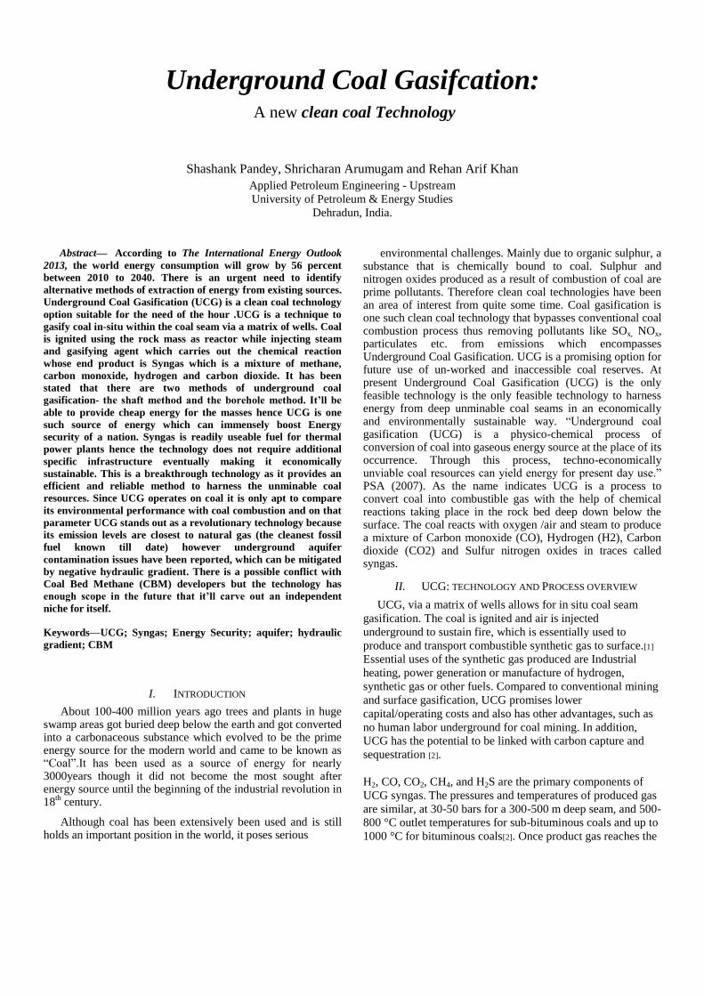
UCG has been approached in many different ways. The
old technique to gasify the coal in situ uses two-vertically
drilled wells as the Injection and Production wells. The
procedure consists of three steps as shown in Fig. 3
Fig. 3. Potential development of UCG: Step 1: well drilling and link establishment. Step
2: coal seam ignition and commencement of gasification and step 3: site clean-up by
flushing cavity with steam and water to remove potential contaminants[3].
In the first step, from the surface to the coal seam and highly
permeable path within the coal seams are established between
these two well by drilling an injection and production well.
Prior to the gasification step a linkage path is created between
injector and producer. Several techniques can be used for
linking the wells, including the Reverse Combustion Linking
(RCL), Forward Combustion Linking (FCL), hydro-fracking,
electro-linking, explosive and in-seam linking. Other
techniques for the in situ gasification include CRIPs, long and
large tunnel gasification, and two-stage UCG [4-6].
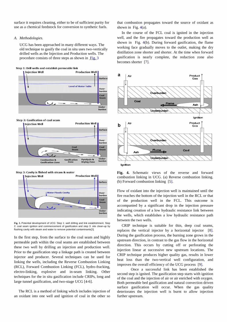
The RCL is a method of linking which includes injection of
an oxidant into one well and ignition of coal in the other so
that combustion propagates toward the source of oxidant as
shown in Fig. 4(a).
In the course of the FCL coal is ignited in the injection
well, and the fire propagates toward the production well as
shown in Fig. 4(b). During forward gasification, the flame
working face gradually moves to the outlet, making the dry
distillation zone shorter and shorter. At the time when forward
gasification is nearly complete, the reduction zone also
becomes shorter [7].
Fig. 4. Schematic views of the reverse and forward
combustion linking in UCG. (a) Reverse combustion linking.
(b) Forward combustion linking [5].
Flow of oxidant into the injection well is maintained until the
fire reaches the bottom of the injection well in the RCL or that
of the production well in the FCL. This outcome is
accompanied by a significant drop in the injection pressure
indicating creation of a low hydraulic resistance link between
the wells, which establishes a low hydraulic resistance path
between the two wells.
CRIP technique is suitable for thin, deep coal seams,
replaces the vertical injector by a horizontal injector [8].
During the gasification process, the burning zone grows in the
upstream direction, in contrast to the gas flow in the horizontal
direction. This occurs by cutting off or perforating the
injection linear at successive new upstream locations. The
CRIP technique produces higher quality gas, results in lower
heat loss than the two-vertical well configuration, and
improves the overall efficiency of the UCG process [9].
Once a successful link has been established the
second step is ignited. The gasification step starts with ignition
of the coal and the injection of air or air enriched with oxygen.
Both permeable bed gasification and natural convection driven
surface gasification will occur. When the gas quality
deteriorates the injection well is burnt to allow injection
further upstream.
When a mixture of air or oxygen and steam is forced into
the coal seam through injection well and react chemically with
the coal, gasification occurs, generating a synthesis gas, which
is recovered through product well. At the surface the raw
product gas is cleaned for industrial uses [10]. As gasification
proceeds, an underground cavity is formed. Water from the
surrounding strata will enter the cavity and participate in the
gasification process leading to a drop in the local water table.
At some point, the coal in the vicinity of the injection well will
be exhausted and steps one and two will be repeated to access
fresh coal to sustain gas production. In the commercial
operations several underground gasifiers will be operated
simultaneously. Once the gasification operations in a section
of coal seam have finished, the third step is to return
environment back to its original state. This is achieved by
flushing the cavities with steam and/or water to remove
pollutants from seams to prevent them from diffusing into
surrounding water aquifers. Over the time, the water table will
return to a level close to that existing prior to the start of
gasification [10]. The composition of the product gas from
UCG can very substantially depending on the injected oxidant
used, operating pressure and mass and energy balance of the
under-ground reactor.
CRIP technique, is suitable for thin, deep coal seams, replaces the vertical injector by a horizontal injector [8]. The CRIP method requires two horizontal wells drilled along a coal seam. One is near the top of the seam and the other near the bottom. The bottom (injection) well is lined with metal pipe. The upper well is the production well. As pyrolysis proceeds, the burn cavity moves toward the base of the wells, progressively exposing more and more of the injection pipe. At an appropriate time, the pipe is melted or burned off and a new period of pyrolysis begins. In effect, the old problems of well plugging are circumvented by simply starting a new burn periodically along the horizontal wells [11]. The CRIP method was first tried successfully in early 1982 with a three-day trial, gasifying a 40-ton cavity. The injection pipe was then burned off and a second 10-ton cavity started. The original cavity cooled to 500
oC, and the second achieved the typical
operating temperature of 1000 oC. The average heating values
of the product gases were between 265 and 277 Btu per standard cubic foot. Burning is started by pyrophoric silane and propane gases. The silane ignites upon encountering the oxygen in the burn cavity and burns long enough to subsequently ignite the propane, which is injected into the well. The propane actually ignites the coal in the cavity. At a suitable time, the propane is shut off and the pyrolysis sustains itself. This method has proved reliable since its adoption. Burning can also be started by passing LPG through the injection well for a short period of time (3-5 min) to initiate the combustion. An electric spark is generated for ignition of the liquefied petroleum gas (LPG) in the channel of the coal block near the mouth of the injection well. Once coal is ignited, the LPG supply is stopped and oxygen is continuously passed through the channel created in the coal block until the completion of the experiment [12].
CRIP technique uses a combination of conventional and direc-
tional drilling to drill the process wells. First, the vertically-
drilled Production Well is drilled until it intersects the coal
seam. Then the vertical section of the Injection Well is drilled
to a pre-determined depth, after which directional drilling is
used to deviate the hole and drill along the coal seam until it
intersects the Production Well. This technique enables the
injection point (i.e. the end of the coiled tubing) to be retracted
back along the coal seam, which is of benefit because it allows
for fresh coal to be accessed each time the syngas quality
drops as a result of cavity maturation. Retraction of the
injection point along the coal seam is known as a CRIP
maneuver, and between 10 and 20 such maneuvers are
expected during the course of a module’s lifetime. Directional
drilling is a proven technology in the oil and gas industry.
The in-seam drilling of coal seams has been part of coal
exploitation since at least the 1950s. Underground steering of
boreholes made its commercial entrance in the oil and gas
industry around 1990, when operators established the benefits
of lateral drilling for extending the life of wells and fixed
drilling platforms and for reaching inaccessible locations.
Nowadays directional drilling has become common for coal
bed methane (CBM) and enhanced CBM applications; there
are specialist drilling companies around who supply services
to CBM operators. The focus to-date has been on reducing
costs. UCG has a tighter requirement on accuracy. The ability
of directional drilling to meet these requirements at an
affordable cost is still under review [6]. The CRIP technique
produces higher quality gas, results in lower heat loss than the
two-vertical well configuration, and improves the overall
efficiency of the UCG process [9].
Two-stage UCG is a technique of supplying air and steam
cyclically [13,14]. In the first stage, air is supplied to make
the coal burn and store heat to produce air gas; in the second
stage, steam is supplied to produce water gas. Only if
sufficient heat is stored in the first stage can the
decomposition reactions in the second stage run smoothly and
the water gas with high heating value be ensured. Meanwhile,
the degree of the coal layer decomposition and the production
volume of the gas are totally determined by the temperature
distribution in the coal layers [15]. During in situ coal
gasification remote sensing technique may be used for
mapping underground fracture systems, locating tunnels or
water-bearing strata and mapping burn fronts [16].
B. Chemical Process:
The study considers the quasi-steady burning of a carbon
particle which undergoes gasification at its surface by
chemical reactions, followed by a homogeneous reaction in
the gas phase. The main chemical processes occurring during
coal gasification are drying, pyrolysis, combustion and
gasification of the solid hydro-carbon. These processes occur
in all methods of coal gasification, whether conducted in
surface gasifiers or in situ. From the chemical and
thermodynamic point of view, the UCG process runs
analogically to gasification in the surface reactors [17]. The
most important chemical reactions taking place during
underground coal gasification are listed in Table 2.
Chemical reactions taking place during underground coal gasification.
Reaction equation Reaction DHo298 Equation
rate (Ri) (MJ/kmol) number
C + O2/CO2 R1 393.8 (1)
C + CO2/2CO2 R2 -162.4 (2)
C + H2O/H2 + CO R3 -131.4 (3)
C + 2H2/CH4 R4 74.9 (4)
CO +
1 O2/CO2
R5 285.1 (5)
2
H2 + 1
O2/H2O R6 -0.242 (6)
2
CO + H2O/CO + H2 R7 -0.041 (7)
Chemical reactions (1)to(4) take place on the wall plane of
the coal seams (heterogeneous reactions), while (6) and (7)
reactions occur at the gaseous stage (homogeneous reactions).
In addition to these listed, reactions involving nitrogen and
sulfur are also important. The final product gas consists of
hydrogen, carbon monoxide, carbon dioxide, methane and
nitrogen. Composition and heating value of the product gas
depends on the thermodynamic conditions of the operation as
well as on the composition and temperature of the gasifying
agent employed [17].
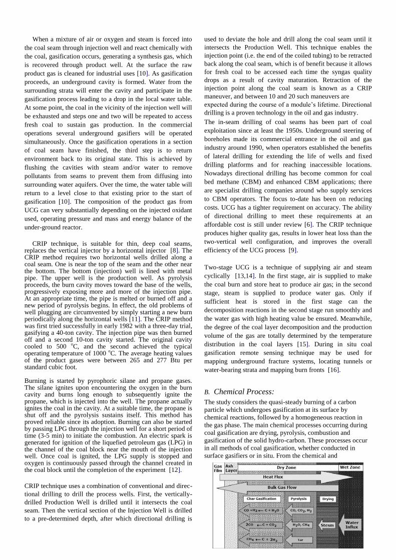
During in situ combustion of coal different processes of
vaporization (drying), pyrolysis, and combustion and
gasification of char take place collectively. The UCG process
has a zonal character and the main gasification reactions occur
both in the solid and the gaseous phases as well as on their
boundaries. Qualitative description of phenomena at the UCG
cavity wall is explained in Fig. 5.
In the solid phase mainly the pyrolysis and the drying
processes take place. Along with the migration of the gaseous
product of the thermal decomposition through the pores and
slots of the solid phase, various homo- and heterogenic
reactions occur. The rates of these processes depend mostly
on the temperature. On the phase boundary in the gasification
channel heterogenic reactions take place. Their rates are
determined by the diffusion and the accessible reaction area.
The major products of the reaction of oxygen with carbon in
the gasification area (oxidation zone) are carbon dioxide and
carbon monoxide [17].
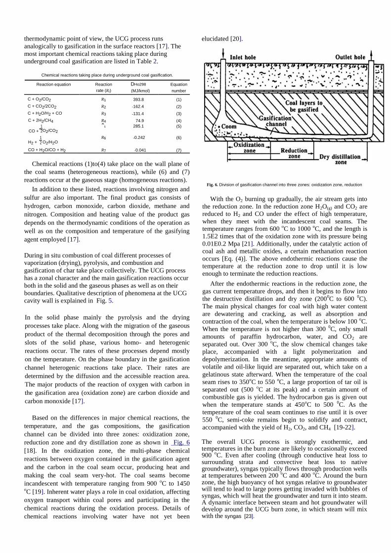
Based on the differences in major chemical reactions, the
temperature, and the gas compositions, the gasification
channel can be divided into three zones: oxidization zone,
reduction zone and dry distillation zone as shown in Fig. 6
[18]. In the oxidization zone, the multi-phase chemical
reactions between oxygen contained in the gasification agent
and the carbon in the coal seam occur, producing heat and
making the coal seam very-hot. The coal seams become
incandescent with temperature ranging from 900 oC to 1450
oC [19]. Inherent water plays a role in coal oxidation, affecting
oxygen transport within coal pores and participating in the
chemical reactions during the oxidation process. Details of
chemical reactions involving water have not yet been
elucidated [20].
Fig. 6. Division of gasification channel into three zones: oxidization zone, reduction
With the O2 burning up gradually, the air stream gets into
the reduction zone. In the reduction zone H2O(g) and CO2 are reduced to H2 and CO under the effect of high temperature,
when they meet with the incandescent coal seams. The temperature ranges from 600
oC to 1000
oC, and the length is
1.5E2 times that of the oxidation zone with its pressure being
0.01E0.2 Mpa [21]. Additionally, under the catalytic action of coal ash and metallic oxides, a certain methanation reaction
occurs [Eq. (4)]. The above endothermic reactions cause the temperature at the reduction zone to drop until it is low
enough to terminate the reduction reactions.
After the endothermic reactions in the reduction zone, the
gas current temperature drops, and then it begins to flow into
the destructive distillation and dry zone (2000C to 600
0C).
The main physical changes for coal with high water content
are dewatering and cracking, as well as absorption and
contraction of the coal, when the temperature is below 100 oC.
When the temperature is not higher than 300 0C, only small
amounts of paraffin hydrocarbon, water, and CO2 are
separated out. Over 300 oC, the slow chemical changes take
place, accompanied with a light polymerization and
depolymerization. In the meantime, appropriate amounts of
volatile and oil-like liquid are separated out, which take on a
gelatinous state afterward. When the temperature of the coal
seam rises to 350oC to 550
oC, a large proportion of tar oil is
separated out (500 oC at its peak) and a certain amount of
combustible gas is yielded. The hydrocarbon gas is given out
when the temperature stands at 450oC to 500
0C. As the
temperature of the coal seam continues to rise until it is over
550 0C, semi-coke remains begin to solidify and contract,
accompanied with the yield of H2, CO2, and CH4 [19-22].
The overall UCG process is strongly exothermic, and temperatures in the burn zone are likely to occasionally exceed 900
oC. Even after cooling (through conductive heat loss to
surrounding strata and convective heat loss to native groundwater), syngas typically flows through production wells at temperatures between 200
oC and 400
oC. Around the burn
zone, the high buoyancy of hot syngas relative to groundwater will tend to lead to large pores getting invaded with bubbles of syngas, which will heat the groundwater and turn it into steam. A dynamic interface between steam and hot groundwater will develop around the UCG burn zone, in which steam will mix with the syngas [23].
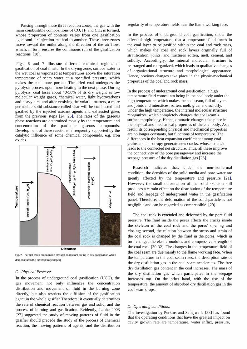
Passing through these three reaction zones, the gas with the
main combustible compositions of CO, H2 and CH4 is formed,
whose proportion of contents varies from one gasification
agent and air injection method to another. These three zones
move toward the outlet along the direction of the air flow,
which, in turn, ensures the continuous run of the gasification
reactions [18].
Figs. 6 and 7 illustrate different chemical regions of
gasification of coal in situ. In the drying zone, surface water in
the wet coal is vaporized at temperatures above the saturation
temperature of seam water at a specified pressure, which
makes the coal more porous. The dried coal undergoes the
pyrolysis process upon more heating in the next phase. During
pyrolysis, coal loses about 40-50% of its dry weight as low
molecular weight gases, chemical water, light hydrocarbons
and heavy tars, and after evolving the volatile matters, a more
permeable solid substance called char will be combusted and
gasified by the injected oxidant agents and exhausted gases
from the previous steps [24, 25]. The rates of the gaseous
phase reactions are determined mostly by the temperature and
concentration of the particular gaseous compounds.
Development of these reactions is frequently supported by the
catalytic influence of some chemical compounds, e.g. iron
oxides.
Fig. 7. Thermal wave propagation through coal seam during in situ gasification which
demonstrates the different regions[26].
C. Physical Process:
In the process of underground coal gasification (UCG), the
gas movement not only influences the concentration
distribution and movement of fluid in the burning zone
directly, but also restricts the diffusion of the gasification
agent in the whole gasifier Therefore; it eventually determines
the rate of chemical reaction between gas and solid, and the
process of burning and gasification. Evidently, Lanhe 2003
[27] suggested the study of moving patterns of fluid in the
gasifier should precede the study of the process of chemical
reaction, the moving patterns of agents, and the distribution
regularity of temperature fields near the flame working face.
In the process of underground coal gasification, under the
effect of high temperature, that a temperature field forms in
the coal layer to be gasified within the coal and rock mass,
which makes the coal and rock layers originally full of
stratification, joints, and fractures soften, melt, cement, and
solidify. Accordingly, the internal molecular structure is
rearranged and reorganized, which leads to qualitative changes
of organizational structure and morphological appearance.
Hence, obvious changes take place in the physic-mechanical
properties of the coal and rock mass.
In the process of underground coal gasification, a high
temperature field comes into being in the coal body under the
high temperature, which makes the coal seam, full of layers
and joints and interstices, soften, melt, glue, and solidify.
Under the high temperature, the internal molecular structure
reorganizes, which completely changes the coal seam’s
surface morphology. Hence, dramatic changes take place in
the physical and mechanical properties of the coal body. As a
result, its corresponding physical and mechanical properties
are no longer constants, but functions of temperature. The
differences in the heat expansion coefficient among coal
grains and anisotropy generate new cracks, whose extension
leads to the connected net structure. Thus, all these improve
the connectivity of the pore passageway and increase the
seepage pressure of the dry distillation gas [28].
Research indicates that, under the non-isothermal
condition, the densities of the solid media and pore water are
greatly affected by the temperature and pressure [21].
However, the small deformation of the solid skeleton still
produces a certain effect on the distribution of the temperature
field and seepage of underground water in the gasification
panel. Therefore, the deformation of the solid particle is not
negligible and can be regarded as compressible [29].
The coal rock is extended and deformed by the pore fluid
pressure. The fluid inside the pores affects the cracks inside
the skeleton of the coal rock and the pores’ opening and
closing; second, the relation between the stress and strain of
the coal rock is changed by the fluid in the pores, which in
turn changes the elastic modulus and compressive strength of
the coal rock [30-32]. The changes in the temperature field of
the coal seam are due mainly to the flame working face. When
the temperature in the coal seam rises, the desorption rate of
the dry distillation gas in the coal seam accelerates. The free
dry distillation gas content in the coal increases. The mass of
the dry distillation gas which participates in the seepage
increases too. On the other hand, with the rise of the
temperature, the amount of absorbed dry distillation gas in the
coal seam drops.
D. Operating conditions:
The investigation by Perkins and Sahajwalla [33] has found
that the operating conditions that have the greatest impact on
cavity growth rate are temperature, water influx, pressure,
and gas composition in underground coal gasification. In this
section, the effect of operating conditions and coal
properties, namely, coal reactivity, operating pressure, heat
loss, and the type of oxidant used are investigated [34].
Lanhe [35] while establishing the mathematical models on
the under-ground coal gasification in steep coal seams
according to their storage conditions and features of gas
production process concludes that numerical simulation on
the temperature field, concentration field and pressure field
is reasonable in the underground gasification of steep coal
seams on the experimental condition.
E. Thickness of Coal Seams:
UCG is influenced by several natural factors as described in Table 3.
Table 3 Classification criteria for UCG.
Criterion Characteristics/remarks
Coal type Any
Physicochemical properties of coal Recommended: high content of volatile
matter, low agglomerating capacity
or its lack, ash content < 50% by weight
Occurrence depth Profitability criterion
Bed thickness More than 1 m
Angle of inclination of coal bed Any
Type and tightness of rock mass Recommended: firmness and tightness
of rock mass, thickness and lithology
of rock massDoverburden in slightly
permeable layers (clays, silts, shale clays)
Hydrogeological conditions Recommended: lack of fissures, faults,
aquiferous layers, water reservoirs causing
water inflow
Deposit tectonics Recommended homogeneity of deposit
(lack of fissure, faults)
Quantity of resources Profitability criterion
Methane presence in the bed Causes gas hazard
Conditions of infrastructure Recommended lack of building development
Most UCG operations were carried out in more gas
permeable conditions of brown coal beds and younger
formations of hard coals. Generally, these deposits occurred
at shallower depths, down to 300 m, and ignited relatively
easily. Strongly swelling and coking coals have the tendency
to block gas flow through the coal bed, thus hindering the
course of the reaction. The gasification of beds 1 m thick or
more improves economics [36]. Beds that are thinner than
0.5 m are not considered suitable for UCG.
In the process of UCG, the burning area and gas are not only
cooled down through heat exchange but a part of the heat is
also lost into the coal seam and surrounding rocks (floor,
roof), thus having an adverse effect on the stability of the
underground gasification process. Eliot [37] suggested that
when the thickness of coal seam is smaller than 2 m, the
cooling action with a dramatic change for surrounding rocks
affects the heat value of coal gas considerably. As for
comparatively thin coal seam, enhancing the blowing velocity
or oxygen-enriched blowing can improve the heating value of
gas. In the former Soviet Union, Lischansk under-ground
gasification station adopted oxygen-enriched blowing in the
coal seam, for which the thickness is less than 2 m [37].
When the thickness of coal layers is decreased or the intake
rate of water is increased, the CO2 content in the gas will rise
[37-38].
F. Effect of Coal Reactivity:
The chemical reactivity of the coal is potentially very
important for UCG. The reported intrinsic reactivities of low
rank coals differ by up to 4 orders of magnitude when
extrapolated to typical gasifier operating temperatures [33].
The coal intrinsic reactivity has a big impact on the
distributions in the gasifier and on the final product gas. In
particular, high reactivity favors the production of methane
via the char-H2 reaction. Because this reaction is exothermic,
the increased reactivity for this reaction can lead to big
changes in the final product gas calorific value.
G. Gasifying Agents:
Gasification under different atmospheres such as air, steam,
steam-oxygen, and carbon dioxide has been reported in the
literature. In general, the gasifier atmosphere determines the
calorific value of the syngas produced. When one uses air as
the gasifying agent, a syngas with low heating value is
obtained. This is mainly due to the syngas dilution by the
nitrogen contained in air. However, if one uses steam or a
combination of steam and oxygen, a syngas with a medium
calorific value is produced. Adding steam changes carbon-
oxygen system balance to carbon-oxygen-steam system
balance in the combustion process. Oxygen-steam gasification
not only utilizes the surplus heat to improve the energy
efficiency of the process, but also increases the gas production
volume per ton of coal and lowers the oxygen consumption
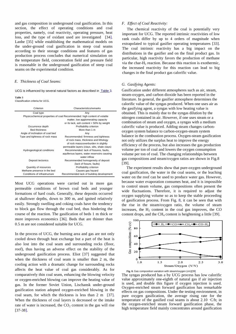
volume per ton of coal. The changing relationships between
gas compositions and steam/oxygen ratios are shown in Fig.8
[39].
The experiment results show that pure-oxygen underground
coal gasification, the water in the coal seams, or the leaching
water on the roof can be used to produce water gas. However,
because water evaporation consumes heat, and it is impossible
to control steam volume, gas compositions often present the
wide fluctuations. Therefore, it is required to adjust the
oxygen supplying volume so as to keep the stable proceeding
of gasification process. From Fig. 8, it can be seen that with
the rise in the steam/oxygen ratio, the volume of steam
increases, the H2 content in the coal gas improves, the CO
content drops, and the CH4 content is heightening a little [39].
Fig. 8. Gas composition variation with steam/oxygen (v/v)[39]
The syngas produced has a by UCG process has low calorific value approximately one-eighth of natural gas if air injection is used, and double this figure if oxygen injection is used. Oxygen-enriched steam forward gasification has remarkable effects on gas compositions. Under the testing environment, in pure oxygen gasification, the average rising rate for the temperature of the gasified coal seams is about 2.10
_C/h; in
the oxygen-enriched steam forward gasification phase, the high temperature field mainly concentrates around gasification
gallery, and the highest temperature in oxidation zone reaches over 1200
oC [40].
The air injected into a gasification channel is at a low speed,
the flame tends to propagate toward the injection point but, if
the air flow rate increases, the cavity tends to grow in the
downstream direction. It is also known that flame propagation
is faster when oxygen is used instead of air. This behavior is
also expected since oxygen-fed flames are hotter and have
higher reaction rates [41].
Saulov et al. [41] considered the limit of high temperatures,
high activation energy and a strong air flow. Under these
conditions the surface of the channel has two zones, cold and
hot. The temperature is insufficiently high in the cold zone to
initiate reactions, while in the hot zone any oxygen on the
surface reacts instantly. Since the activation energy is high,
these zones are separated only by a very small distance. The
overall reaction rate is determined by the rate of diffusion of
oxygen to the hot zone, while the oxygen concentration on
hotwalls is essentially zero. Under such conditions the
turbulent flame is fully controlled by diffusion and the
injection rate has no control over the flame position.
Combustion of coal begins with devolitalization reactions at
low temperatures and can be cooled by the air stream. If these
reactions play a noticeable role in initiating the rest of the
oxidation process or in the overall energy balance, the flame
position is affected by the air speed and becomes controllable.
When other factors are the same, increases in flow rate and
operation time result in monotonic increases in all the
dimensions of the cavity, and its volume. However, when the
distance between the injection and production wells is
increased, the overall cavity volume decreases, due to
significant reduction in the rate of growth of the cavity in the
forward direction [12].
H. Effect Of Pressure:
Pressure is known to positively impact the performance of
coal gasification [42]. At close to atmospheric pressure, the
gas calorific value is very low because of the kinetic
limitations of the gasification reactions. The changes in
operating pressure can perfect the underground gasification
process to a great extent. Under the cyclically changing
pressure condition, heat loss was obviously reduced, and heat
efficiency and gasification efficiency and the heat value of the
product gas are increased greatly. The underground gasifier
with a long channel and big cross-section could improve the
combustion and gasification conditions to a large extent,
markedly bettering the quality of the product gas and the
stability of gas production. Therefore, the large-scale
underground gasifier is a condition necessarily met by the
industrial production [22].
I. Effect Of Heat Loss:
Heat losses from underground coal gasification are not easy to
estimate. If the cavity remains completely in the coal seam,
then heat losses to the surrounding strata will probably be
small and can be ignored. However, as the overburden is
progressively exposed, irreversible heat loss to the
surrounding will increase. It is not easy to estimate this heat
loss, because if the overburden undergoes spalling, some of
the energy used to heat it to cavity temperatures may be
recovered through preheating of the injected gas. The heat loss
mechanisms can probably be more easily investigated using a
dynamic model, in which cavity growth and heat loss are esti-
mated as functions of time, simultaneously.
J. Effect of Temperature:
The process of UCG is virtually one of a self-heat balance.
The heat produced by coal combustion contributes to the
establishment for ideal temperature field in the underground
gasifier and also leads to the occurrence of gasification
reactions and, eventually, the generation of gas.
Temperature is a key factor in determining the continuous and
stable production in the process of underground coal
gasification. The patterns of variation for temperature field in
the gasifier are closely related to the nature of the gasification
agent, gasification modes, and the changes of cavity [21,40].
Under the pure oxygen gasification condition, the average
rising rate for the temperature of the gasified coal seams is
about 4.15 oC/h; in the oxygen-steam forward gasification
phase the high temperature field mainly concentrates around
loosening zones arising from the thermal explosions, and the
highest temperature in the oxidation zone approaches 1300 oC
[43]. Compared with forward gasification, the average
temperature in the gasifier for backward gasification is lowers
[40]. The drop of temperature results in a decrease in CO
content while H2, CH4 and CO2 contents increases [22]. In thermal-explosion gasification method, under the pure
oxygen gasification condition, the average rising rate for the temperature of the gasified coal seams is about 4.15
oC/h; in
the oxygen-steam forward gasification phase, temperature field mainly concentrates around loosening zones arising from the thermal explosions, and the highest temperature in the oxidation zone approaches 1300
0C. Test data showed that the
forward oxygen-steam gasification with moving points can obviously improve the temperature conditions in the gasifier. During the backward oxygen-steam gasification, with the passage of time, the temperature of the gasification coal seams continuously increases, approaches stable little by little, and was basically the same with that of the forward gasification. Therefore, backward gasification can form new temperature conditions and improve the gasification efficiency of the coal seams.
In the process of coal gasification, the changes of the
temperature in the coal seam are due mainly to the heat
transfer medium of the flame working face, which corresponds
to a source of heat [28]. In the process of underground coal
gasification, the temperature of coal seams around the
gasification channel rises along with the conducted heat.
When the coal surface is heated by the hot gas or the
neighboring incandescent coal, its temperature distribution
expands toward the coal grains or the interior of the coal seam,
which inevitably results in the thermal effects of absorption,
desorption, and seepage movement of dry distillation gas
stored in the coal seam [21, 28]. King and Ertekin [44] study
shows that under non-isothermal conditions, either the
absorption-desorption process or the permeation-expansion
process is linked to the temperature.
According to the gasification theory, the temperature above
1000 oC indicates a high-speed diffusion of the water
decomposition reaction constituting the fundamental process for the production of a hydrogen rich gas in the course of the UCG steam stage. On the other hand, the temperature drop below 700
0C slowed down the reaction speed considerably.
For these reasons, special attention was paid to keeping parameters preferable for the production of gas with a high content of the combustible components, mainly hydrogen. The oxygen stage was therefore continued to achieve temperatures in the range between 1100 and 1200
oC.
According to the simulated calculation results [35], with the
increase of the length for the gasification channel, the heating
value of the gas improves. However, behind the reduction
zone, it increases with a smaller margin. The influence of the
temperature field on the heating value for the gas is noticeable.
Due to the effect of temperature, in high temperature zone, the
change of the measured value of the concentration field for the
gas compositions is larger than that of calculated value.
The underground gasification of a large quantity of coal at
temperatures higher than 1000 oC results in the typically
argillaceous overburden rocks overlying the coal becoming
thermally affected. Most of thermal reactions in argillaceous
rocks are endothermic.
K. Cavity Growth:
As the coal gasification reaction precedes a cavity
consisting of coal, char, ash, rubble, and void space, is created
underground. The size of the cavity formed during UCG
impacts directly the economic and environmental factors
crucial to its success. Lateral dimensions influence resource
recovery by determining the spacing between modules, and
ultimate overall dimensions dictate the hydrological and
subsidence response of the overburden. The exact shape and
size of the gasification channel during UGC are of vital
importance for the safety and stability of the upper parts of the
geological formation [45]. Due to upward growth the cavity
eventually reaches the interface between the coal seam and the
overburden. From that point onwards the development of the
cavity can be strongly influenced by the interaction of the gas
mixture with the over-burden. At the start of the UCG process,
typically, the exothermic coal combustion reaction is required
in order to create a sufficiently large underground cavity. In
this early stage, cavity growth is unconstrained by roof
interactions. Once a stable temperature field is attained, steam
is introduced in the cavity for gasification of the coal in order
to obtain the combustible product gases [7]. The shape and
rate of growth of this cavity will strongly impact other
important phenomena, such as reactant gas flow patterns,
kinetics, temperature profiles, and so on [12]. The cavity size
at any given time depends on the rate of coal consumption and
its shape depends on the non-ideal flow patterns inside the
cavity.
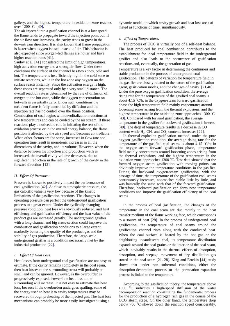
The cavity shape is almost symmetric around the injection
well. The cavity evolution behind the injection well (i.e.
backward length) is less than the height (in the vertical
direction) and the width at the injection point (in the
transverse direction). The forward length of the cavity (i.e.
distance from injection well to the end point of the cavity
dome in the forward direction) is larger than the height and the
backward length. The convective flux of the reactant gases in
the forward direction (i.e. toward the production well)
contributes to the additional growth of the cavity in this
direction. The observed final cavity dome that is associated
with a long outflow channel is nevertheless nearly
hemispherical in shape. Fig. 9 is a schematic of the final
cavity shape, indicating the vertical, forward, backward and
transverse directions as defined here. Fig. 9. Schematic diagram defining forward length, backward length, height and width of
the final cavity[12].
The temperature at the cavity roof is in the range of 950-1000 0C whereas the floor temperature varies between 650 and 700
oC. The volume of the cavity increases progressively with coal
consumption and thermo mechanical spalling, if any, from the
roof. As the cavity growth is irregular in three dimensions, the
flow pattern inside the UCG cavity is highly non-ideal. The
complexity increases further because of several other
processes occurring simultaneously, such as heat transfer due
to convection and radiation, spalling, water intrusion from
surrounding aquifers, several chemical reactions, and other
geological aspects [36]. Several mathematical models have
been developed considering the UCG cavity as either a packed
bed or a free channel Most of the existing models consider the
UCG cavity as a rectangular or cylindrical channel [4,33,35].
Perkins and Sahajwalla [33] predicted cavity growth rate
between 1.6 and 5 cm/h using their mathematical model which
links linear cavity growth rates to reactivity and mass transport
properties. Daggupati et al.[7] measured the linear, vertical
growth rate of 1.1 cm/h (obtained using the measured cavity
heights at different times, with the other operating conditions
being the same).
The cavity volume is directly proportional to the coal
consumption whereas the shape depends on the relative rates
of growth taking place in each of the four identified
representative directions. While the coal consumption is
governed by the extent or rate of reaction that takes place in
the cavity reactor, the growth in each individual direction is a
function of the complex reactant gas flow field inside the
cavity, and other effects such as thermo mechanical spalling of
the coal. Chen et al. [45] has developed model to calculate the
temperature distribution in the vertical direction, and the
combustion volume.
According to the physical and chemical properties of coal
and the mining geology conditions of the burial for the coal
seams, two kinds of gasification channels can be formed in the
gasification panel; namely, free channel without solid phase
and the percolation patterned porous loose channel. In the
longitudinal (or radial) direction, the free channel can be
divided into three zones (Fig. 10), i.e., free flowing zone,
reaction zone and the coal seams zone.
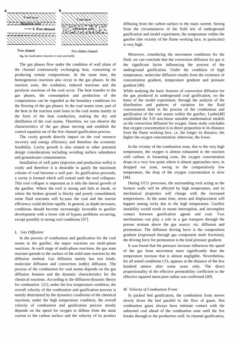
Fig. 10. Gasification channels in coal seems[46].
The gas phases flow under the condition of wall plane of
the channel continuously exchanging heat, consuming or
producing certain compositions. At the same time, the
homogeneous reactions also occur to the gas phases. In the
reaction zone, the oxidation, reduced reactions and the
pyrolysis reactions of the coal occur. The heat transfer to the
gas phases, the consumption and production of the
compositions can be regarded as the boundary conditions for
the flowing of the gas phases. In the coal seams zone, part of
the heat in the reaction zone loses in the coal seams mainly in
the form of the heat conduction, making the dry and
distillation of the coal seams. Therefore, we can observe the
characteristics of the gas phase moving and establish the
control equation set of the free channel gasification process.
The cavity growth directly impact on the coal resource
recovery and energy efficiency and therefore the economic
feasibility. Cavity growth is also related to other potential
design considerations including avoiding surface subsidence
and groundwater contamination.
Installation of well pairs (injection and production wells) is
costly and therefore it is desirable to gasify the maximum
volume of coal between a well pair. As gasification proceeds,
a cavity is formed which will extend until the roof collapses.
This roof collapse is important as it aids the lateral growth of
the gasifier. Where the roof is strong and fails to break, or
where the broken ground is blocky and poorly consolidated,
some fluid reactants will by-pass the coal and the reactor
efficiency could decline rapidly. In general, as depth increases,
conditions should become increasingly favorable to gasifier
development with a lower risk of bypass problems occurring,
except possibly in strong roof conditions [47].
L. Gas Diffusion:
In the process of combustion and gasification for the coal
seams in the gasifier, the major reactions are multi-phase
reactions. At each stage of multi-phase reactions, the gas state
reactant spreads to the surface of the solid state reaction by the
diffusion method. Gas diffusion mainly has two kinds:
molecular diffusion and convection (eddy) diffusion. The
process of the combustion for coal seams depends on the gas
diffusion features and the dynamic characteristics for the
chemical reactions. According to the diffusion-dynamic theory
for combustion [21], under the low temperature condition, the
overall velocity of the combustion and gasification process is
mainly determined by the dynamics conditions of the chemical
reactions; under the high temperature condition, the overall
velocity of combustion and gasification process mostly
depends on the speed for oxygen to diffuse from the main
current to the carbon surface and the velocity of its product
diffusing from the carbon surface to the main current. Seeing
from the circumstances of the field test of underground
gasification and model experiment, the temperature within the
gasifier (the vicinity of the flame working face, in particular)
is very high.
Moreover, considering the movement conditions for the
fluid, we can conclude that the convection diffusion for gas is
the significant factor influencing the process of the
underground gasification. Under the condition of high
temperature, molecular diffusion results from the existence of
concentration gradient, temperature gradient and pressure
gradient [48].
While studying the basic features of convection diffusion for
the gas produced in underground coal gasification, on the
basis of the model experiment, through the analysis of the
distribution and patterns of variation for the fluid
concentration field in the process of the combustion and
gasification of the coal seams within the gasifier, Lanhe[48]
established the 3-D non-linear unstable mathematical models
on the convection diffusion for oxygen. Same study concludes
that oxygen concentration is in direct proportion to its distance
from the flame working face, i.e. the longer its distance, the
higher the oxygen concentration; otherwise, the lower.
In the vicinity of the combustion zone, due to the very high
temperature, the oxygen is almost exhausted in the reaction
with carbon; in loosening zone, the oxygen concentration
drops to a very low point where it almost approaches zero; in
dropped out zone, owing to the comparatively low
temperature, the drop of the oxygen concentration is slow
[48].
During UCG processes, the surrounding rock acting as the
furnace walls will be affected by high temperature, and its
mechanical properties will change with the increased
temperatures. At the same time, stress and displacement will
happen among rocks due to the high temperature. Gasifier
instability would result in steam interruption, and incomplete
contact between gasification agents and coal. Two
mechanisms can play a role in a gas transport through the
porous stratum above the gas source, viz. diffusion and
permeation. The diffusion driving force is the composition
gradient (expressed through gas component mole fractions);
the driving force for permeation is the total pressure gradient.
It was found that the pressure increase influences the speed
of the gas front movement more significantly than the
temperature increase that is almost negligible. Nevertheless,
for all tested conditions CO2 appears at the distance of the few
hundred meters after some years only. The direct
proportionality of the effective permeability coefficient to the
effective squared mean pore radius was confirmed [49].
M. Velocity of Combustion Front:
In packed bed gasification, the combustion front moves
slowly down the bed parallel to the flow of gases. Hot
combustion gases always have intimate contact with the
unburned coal ahead of the combustion zone until the fire
breaks through to the production well. In channel gasification,
the combustion zone moves outward at nearly right-angles to
the flow of air and combustion gases. During UCG a thermal
wave is formed which gradually travels through the coal bed
toward the gas production well. The shape of the thermal wave
tends to change very little. Since the shape of the wave
remains unchanged, the processes occurring at each
temperature level in the moving wave remain unchanged in
time, and an apparent steady-state or 10seudo-steady-state
condition prevails. Under these conditions in a one-
dimensional system, it is possible to transform the
mathematical model to a moving coordinate system which
converts partial differential to ordinary differential equations,
a major simplification of the problem. This transformation is
[50]:
n ¼ x E vt
where:
x ¼ fixed spatial
coordinate
t ¼ time v ¼ velocity of thermal wave or combustion front n ¼ coordinate system moving with frontal velocity v
When the physical properties of coal tend to vary widely
over short distances even in a single coal seam making the
task of modeling such as UCG process very complex.
Gasification of typical 9 m seam of sub-bituminous coal
proceeds at a rate of 0.3E0.6m/ day consuming all the coal in a
swath 12 to 15 m wide for a well spacing of approximately 18
m. The precise proportions of the various component gases in
any particular syngas mixture are a function of quality and
rank of coal, seam depth, steam: oxygen ration and oxygen
injection rate and other parameter discussed in Section 2.
Compositions of syngas from a variety of coals as reported in
literature reveals component fractions in the following ranges
[31]. At constant steam/oxygen ratio gas compositions
remained stable [51].
N. UGC Optimization:
Underground gasification cannot be controlled to the same
extent as a surface process as the coal feed cannot be
processed. The UCG process can be operated with stability
and flexibility, as input flow has been shown to have a direct
relationship to production flow, with little effect on product
gas quality. The power output from the gasifier could be
rapidly increased or reduced by increasing or decreasing the
O2 flow rate. Although elevated depth and pressure are not
pre-requisites for a high quality gas, the benefit is in higher
mass flows and hence greater efficiency of energy
transmission to the surface. The energy output of a UCG
system depends on the flow rate of gaseous products and the
heat value of the gas mixture. The volume flow of the product
gas is typically four times the injection flow so the limiting
factor is the dynamic resistance of the production well. The
mass flow capability of a well is proportional to input
pressure. Increasing well depth increases the product gas
density and pressure. The mass flow gain due to pressure
increase exceeds the frictional loss due to increased borehole
length. Increasing the diameter of production tubing also
raises the limiting flow rate. Increasing the diameter of
production tubing, or the number of production wells, also
raises the limiting flow rate [47]. Information on the process
conditions must be constantly monitored and updated as the
gasification process moves forward. The ideal temperatures of
above ground coal gasification are about 1000 oC, however, it
may or may not be possible to achieve these temperatures in
UCG, primarily because of the lack of control on water influx
and reactant gas flow patterns [36]. Blinderman et al. [5] Has
used intrinsic disturbed flame equations to determine the key
parameters of the RCL process. Wang et al.[52] performed
field trial with various operational maneuvers, such as
implementing controlled moving injection points, O2-enriched
operation and variation of operational pressure to ensure the
gas flow comparatively controllable and hence improve
efficiency of heat and quality of the production syngas.
Lawrence Livermore National Laboratory (LLNL) is
evaluating commercial computational fluid dynamics (CFD)
code to model cavity gas flow and combustion in two and
three dimensions. Fig. 11 [53] shows a typical cavity
configuration at a mid-to-late stage of a linked vertical well
module. Nitao et al. [53] has provided the details of models
and simulators. It will be more useful to couple the UCG
process models with full scale process simulator so that the
entire process can be modeled at once, rather than
sequentially.
III. UCG: TECHNOLOGY RELEVANCE TO INDIAN
PERSPECTIVE
Coal is the single largest energy source for India with total
estimated reserves of about 293 billion tones i.e. roughly 8% of
world’s total coal reserves [54]. It accounts for 55% of total
primary commercial energy production. 75% of produced coal
in India is consumed in the power sector. In addition other
industries like steel cement fertilizer chemicals and other small
scale industries account for the usage of rest of it. The total
recoverable coal reserves have been estimated to be only about
15.6% (43 billion tones) leaving about 250 billion tones
unminable. If India wants to be energy secure it is of extreme
importance to utilize our prime energy source to the fullest.
India, the third largest economy in terms of Purchase Power
Parity (PPP) with a net Gross Domestic Product (GDP) of 6776
Billion USD is growing at an average rate of 7.5 % since the
last 15 years [55]. The current total energy demand of India is
approximately 700 million tons of oil equivalents (MMTOE)
making it fourth largest consumer of energy of the world after
United States, China and Russia. About 65% of this energy
requirement is met indigenously which makes India one of the
largest energy importers of the world [56]. Thus the Indian
Govt. faces formidable challenge of coping with substantial
energy crisis and supply of affordable energy to the masses.
And Underground Coal gasification is the answer to India’s
energy problems as it has many advantages over conventional
mining. The relevance of this technology to Indian perspective
can be understood by comparing Indian coal to that already
used in test/plot plants globally.
A. Indian Coals:
India has a huge coal reserve but most of it is non-coking coal
comprising semi-bituminous and ignites (a brown variety of
tertiary Indian coal that has relatively less energy/heating vale).
Coal which when heated in the absence of air forms coherent
beads, free from volatiles, with a strong and porous mass called
coke, is called coking coal. Coals which do not have coking
properties, are non-coking coals. Moreover most of the minable
coal of India is concentrated in small patch of Eastern India
(Bihar, Jharkhand and West Bengal).
B. Coal Depth and Thickness:
The coal occurrence at various depth levels in India is
categorized in Table 9.
Table 9 Indian coal reserves at various depths (in million tonnes) [57]
Depth (m) Proved
Indicate
d Inferred Total
%
Total
reserve reserve reserve reserve
Reserv
e
0–300 54 627.35 54 242.51 20 519.91 129 389.77 62.74
300–600 18 929.82 25 694.76 17 384.94 62 009.52 30.07
600–1200 1560.58 9141.99 4137.64 14 840.21 7.19
Total 0–
1200 75 117.75 89 079.26 42 042.49 206 239.50 100
A total of 62.74% of the coal deposits lie at a depth of 0–300
m, 30.07% at 300–600 m and 7.19% coal is at a depth of 600–
1200 m.[58]. At many places like Madhya Pradesh, West
Bengal, Maharashtra and Assam both the coal seam depth(
>300m) and thickness( >2m) are suitable for UCG but still it
has been found that UCG pilot plants can be setup in Madhya
Pradesh and West Bengal only and not in Maharashtra and
Assam because of the less availability of coal in terms of
quantity.
C. Lignite Depth and Thickness:
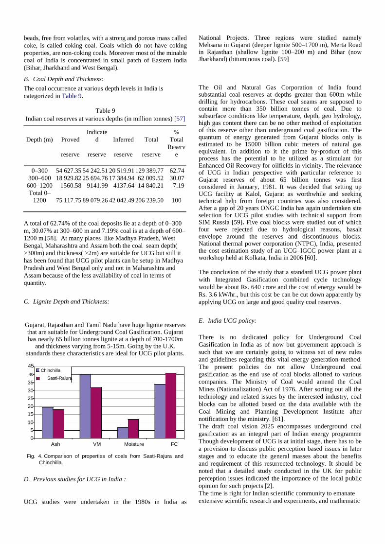
Gujarat, Rajasthan and Tamil Nadu have huge lignite reserves that are suitable for Underground Coal Gasification. Gujarat has nearly 65 billion tonnes lignite at a depth of 700-1700m
and thickness varying from 5-15m. Going by the U.K. standards these characteristics are ideal for UCG pilot plants.
45
Chinchilla 40
Sasti-Rajura
35
30
25
20
15
10
5
0 Ash VM Moisture FC
Fig. 4. Comparison of properties of coals from Sasti-Rajura and Chinchilla.
D. Previous studies for UCG in India :
UCG studies were undertaken in the 1980s in India as
National Projects. Three regions were studied namely Mehsana in Gujarat (deeper lignite 500–1700 m), Merta Road in Rajasthan (shallow lignite 100–200 m) and Bihar (now Jharkhand) (bituminous coal). [59]
The Oil and Natural Gas Corporation of India found substantial coal reserves at depths greater than 600m while drilling for hydrocarbons. These coal seams are supposed to contain more than 350 billion tonnes of coal. Due to subsurface conditions like temperature, depth, geo hydrology, high gas content there can be no other method of exploitation of this reserve other than underground coal gasification. The quantum of energy generated from Gujarat blocks only is estimated to be 15000 billion cubic meters of natural gas equivalent. In addition to it the prime by-product of this process has the potential to be utilized as a stimulant for Enhanced Oil Recovery for oilfields in vicinity. The relevance of UCG in Indian perspective with particular reference to Gujarat reserves of about 65 billion tonnes was first considered in January, 1981. It was decided that setting up UCG facility at Kalol, Gujarat as worthwhile and seeking technical help from foreign countries was also considered. After a gap of 20 years ONGC India has again undertaken site selection for UCG pilot studies with technical support from SIM Russia [59]. Five coal blocks were studied out of which four were rejected due to hydrological reasons, basalt envelope around the reserves and discontinuous blocks. National thermal power corporation (NTPC), India, presented the cost estimation study of an UCG–IGCC power plant at a workshop held at Kolkata, India in 2006 [60]. The conclusion of the study that a standard UCG power plant
with Integrated Gasification combined cycle technology
would be about Rs. 640 crore and the cost of energy would be
Rs. 3.6 kW/hr., but this cost be can be cut down apparently by
applying UCG on large and good quality coal reserves.
E. India UCG policy:
There is no dedicated policy for Underground Coal
Gasification in India as of now but government approach is
such that we are certainly going to witness set of new rules
and guidelines regarding this vital energy generation method.
The present policies do not allow Underground coal
gasification as the end use of coal blocks allotted to various
companies. The Ministry of Coal would amend the Coal
Mines (Nationalization) Act of 1976. After sorting out all the
technology and related issues by the interested industry, coal
blocks can be allotted based on the data available with the
Coal Mining and Planning Development Institute after
notification by the ministry. [61].
The draft coal vision 2025 encompasses underground coal
gasification as an integral part of Indian energy programme
Though development of UCG is at initial stage, there has to be
a provision to discuss public perception based issues in later
stages and to educate the general masses about the benefits
and requirement of this resurrected technology. It should be
noted that a detailed study conducted in the UK for public
perception issues indicated the importance of the local public
opinion for such projects [2].
The time is right for Indian scientific community to emanate
extensive scientific research and experiments, and mathematic
modelling and simulations of Indian coal along with site
specific field trials.
IV. ADVANTAGES OF UCG
UCG offers significant advantages both in terms of ecological
and economical over traditional coal mining and gasification
methods, which is indeed of utmost importance for a rapid
developing country like India.
A. Ecological Benefits:
UCG permits lower emissions and air pollution
because gasification in UCG is underground thus it
reduces environment management costs.
Suspended Particulate Matter (SPM) is generated at
half the rate of surface equivalent technologies and
most of the particulates generated are confined to
subsurface.
There is a substantial decrease in noise and visual
impact on the surface due to this process.
Since UCG is applied on deeper coal seams and
according to DTI-UK standard a vertical separation
of 100m or above is to be maintained between nearest
aquifer and UCG rock bed reactor site, hence there is
a low risk of groundwater contamination.
Methane (naturally occurring over coal beds) is
recovered in this process, unlike the conventional
coal technologies which helps in reduced Greenhouse
Gas emissions.
Amount of water required in this technology is very
less in comparison to other coal technologies as water
is used as a reactant only and there is no need of coal
washing in this process.
B. Economical Benefits:
Unlike conventional gasification facilities there is no
need to procure surface gasifiers or build ash and slag
management facilities hence UCG aids in reduction
of Capital Expenditure.
Storage, transportation and preparation of coal is not
required in this technology which helps in reduction
of operating costs.
Since it is a clean technology environment
management costs are saved.
There is no risk of supply disruption, providing clear
advantages in secure fuel supplies.
Syngas can be piped directly to the end user,
reducing the need for rail/road infrastructure and the
expenditure associated thereof.
Additional power generation infrastructure is not
required as the produced syngas can be directly
utilized by conventional gas based thermal power
plants.
C. Collateral Benefits:
1. UCG-CCS Integration: CBM development
If the greenhouse gas (GHG) emission reductions sought by
government and world climate bodies are to be met, then
modern technical solutions are to be employyed. Moost
scientific reviews promote CO2 capture and storage(CCS) as
the most promising technology to lower fossil fuel
emissions.UCG already incorporates many advantages over
traditional coal extraction methods making it cleaner;
combining UCG and CCS wouuld offer even greater reduction
in emissions.
UCG in combination with CCS is recognized as potential
route to carbon abatement from coal. Report suggests that
UCG in combination with CO2 injection into adjacent coal
seams to enhance Coal Bed Methane (CBM) is a potentially
attractive option. Recent tests in Australa have shown that
considerable quantities of Methane can be extracted using
UCG and at a lower cost than CBM.
2. UCG-CCS Integration: Enhanced Oil Recovery
CO2 generated from UCG operations can be sequestrated into
mature oilfield which will help in optimizing crude oil
production from ageing fields. Injecting carbon dioxide
creates pressure in reservoir which iincreases the drive force
directing oil trough the production tubing to rise upto the
surface. CO2 increases the sweep efficiency of the productiion
operation and hence is on of the most suitable stimulant for
enhanced oil recovery. It will be dual benefit as problem of
waste/emission management will be resolved and increased oil
production would strengthen the nation by pushing it step
closer to energy security.
V. CHALLENGES AND MITIGATION
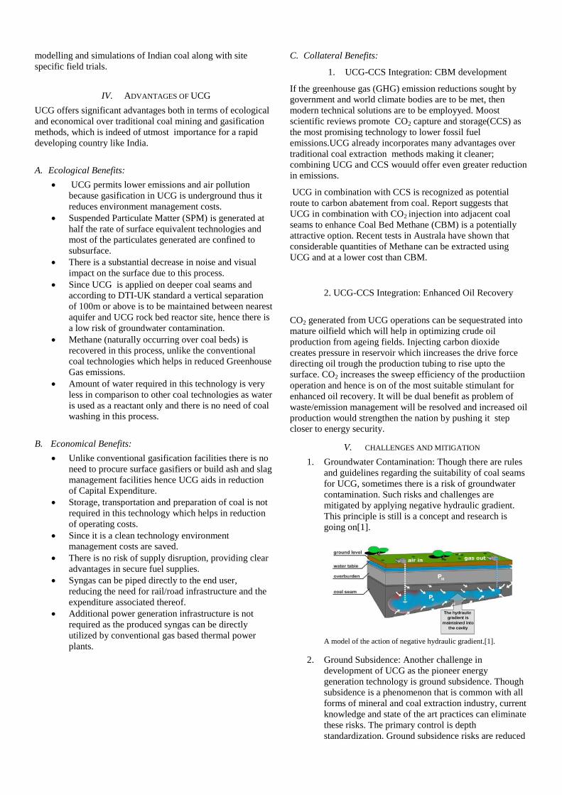
1. Groundwater Contamination: Though there are rules
and guidelines regarding the suitability of coal seams
for UCG, sometimes there is a risk of groundwater
contamination. Such risks and challenges are
mitigated by applying negative hydraulic gradient.
This principle is still is a concept and research is
going on[1].
A model of the action of negative hydraulic gradient.[1].
2. Ground Subsidence: Another challenge in
development of UCG as the pioneer energy
generation technology is ground subsidence. Though
subsidence is a phenomenon that is common with all
forms of mineral and coal extraction industry, current
knowledge and state of the art practices can eliminate
these risks. The primary control is depth
standardization. Ground subsidence risks are reduced
manifold when the coal seams to be gasified in-situ
are at depths greater than 200m. Subsidence can
further be reduced by using alternative UCG designs
with narrow cavities because roof collapses only
when the reactor cavity widens more than what is
estimated.
VI. CONCLUSION AND FUTURE PROSPECTS
UCG no doubt is the most suitable technology present today
for utilization of almost all inaccessible and unable coal
reserves. It is an old technology and has been proven to come
good on all what is expected of it. The only thing is evolve
this to create a new power generation mechanism which will
create an energy self-sufficient India. The government must
take steps to recognize this as potential pathway to energy
security and take appropriate measures which include making
robust UGC policy, attract corporate sector for investment into
the concerned energy sector. The technology is promising and
has enough scope in future. A ready testimonial to this
technology exists in the name of underground coal seam fires.
Underground coal fires are common all over world. Most of
them are severe and out of control. One such fire has burned in
the Jharia coal field of India for nearly a century. Leave aside
the amount of coal that has already burnt, reports suggest that
is if the burning continues at the present rate it will continue
for more than centuries to come. The need of the hour is to
find or discover some or the other way/technology that can
help in utilization of this burning coal. Underground Coal
Gasification is the first step and the foundation towards
development of required technology. There is a requirement to
utilize the heat of burning coal to carry on the chemical
reaction to gasify coal by limiting the heat to the required
value.
VII. REFERENCES
[1] Bhutto AW,Bazmi AA, Zahedi G.Underground Coal Gasification:from Fuundamental to
Applications.2013.Progress in Energy and Combustion Science.Elsevier
[2] Shackley S, Mander S, Reiche A. Public perceptions of underground coal
gasification in the United Kingdom. Energy Policy 2006;34(18):3423E33
[3] Perkins G, Sahajwalla V. A mathematical model for the chemical reaction of a semi-
infinite block of coal in underground coal gasification. Energy & Fuels 2005;19(4):1679E92. http://dx.doi.org/10.1021/ef0496808.
[4] Biezen ENJ, Bruining J. An integrated 3D model for underground coal gasi-fication. SPE Annual Technical Conference and Exhibition, 22E25 October 1995; Dallas, Texas: Society of Petroleum Engineers; 1995. [5] Blinderman MS, Saulov DN, Klimenko AY. Forward and reverse combustion linking in underground coal gasification. Energy 2008;33(3):446E54. [6] Roddy DJ, Younger PL. Underground coal gasification with CCS: a pathway to decarbonising industry. Energy & Environmental Science 2010;3(4):400E7 [7] Yang L, Zhang X, Liu S, Yu L, Zhang W. Field test of large-scale hydrogen manufacturing from underground coal gasification (UCG). International Journal of Hydrogen Energy 2008;33(4):1275E85.
[8] Hill RW, Shannon MJ. The controlled retracting injection point (CRIP) system: a
modified stream method for in situ coal gasification. Berkeley, CA: Lawrence Livermore National Laboratory (LLNL) Report; 1981. Contract No.: UCRL-85852 [9] Thorsness CB, Hill RW, Britten JA. Execution and performance of the CRIP process during the rocky mountain I UCG field test. Berkeley, CA: Lawrence Livermore National Laboratory (LLNL) Report; 1988. Contract No.: UCRL-98641. [10] Perkins G. Mathematical modelling of underground coal gasification. The University of New South Wales; 2005 [11] Haggin J. Key tests set for underground coal gasification. Chemical & Engi-neering News 1983;61(29):15E9. http://dx.doi.org/10.1021/cen-v061n029. p015 [12] Daggupati S, Mandapati RN, Mahajani SM, Ganesh A, Mathur DK, Sharma RK, et al. Laboratory studies on combustion cavity growth in lignite coal blocks in the context of underground coal gasification. Energy 2010;35(6):2374E86 [13] Yang LH, Yu L, Liang J. In: The coal gasification in the discarded mines and comprehensive use of its product gas, vol. 16. Min World; 1995. p. 20. [14] Yang L. The dynamic temperature field of two-stage underground coal gasification (UCG). Energy Sources, Part A: Recovery, Utilization, and Environmental Effects 2006;28(7):667E80. http://dx.doi.org/10.1080/ 009083190951438. [15] Guo C. In: Review of mathematical simulation study on the underground coal gasification, vol. 15. Mining World; 1994. p. 3E5 [16] Daily W, Lytle J. Geophysical tomography. Journal of Geomagnetism and Geoelectricity 1983;35(11E12):423E42 [17] Stanczyk K, Kapusta K, Wiatowski M, Swiadrowski J, Smolinski A, Rogut J, et al. Experimental simulation of hard coal underground gasification for hydrogen production. Fuel 2012;91(1):40E50. [18] Yang L, Liang J, Yu L. Clean coal technologyDstudy on the pilot project experiment of underground coal gasification. Energy 2003;28(14):1445E60. [19] Wu RY. Coal gasification. Xuzhou: China University of Mining and Tech-nology Press; 1988. p. 68E73. [20] Wang H, Dlugogorski BZ, Kennedy EM. Coal oxidation at low temperatures: oxygen consumption, oxidation products, reaction mechanism and kinetic modelling. Progress in Energy and Combustion Science 2003;29(6):487E513. [21] Yang LH, Song DY. Study on the method of seepage combustion in under-ground coal gasification. Xuzhou, China: China University of Mining and Technology Press; 2001. [22] Yang LH. A review of the factors influencing the physicochemical charac-teristics of underground coal gasification. Energy Sources, Part A: Recovery, Utilization, and Environmental Effects 2008;30(11):1038E49. http://dx.doi. org/10.1080/15567030601082803. [23] Couch G. Underground coal gasification. London, United Kingdom: IEA Clean Coal Centre; 2009. 01/07/2009. Report No.: Contract No.: CCC/151. [24] Campbell JH. Pyrolysis of subbituminous coal as it relates to in situ gasifi-cation. Part 1. Gas evolution. [383 to 1273/sup 0/K in argon]. NTISLLNL; 1976. UCRL-52035(Pt.1) United StatesThu Mar 24 09:14:52 EDT 2011Dep, ERA-01-018449; EDB-76-051202English [25] Merrick D. Mathematical models of the thermal decomposition of coal: 1. The evolution of volatile matter. Fuel 1983;62(5):534E9 [26] Seifi M, Chen Z, Abedi J. Numerical simulation of underground coal gasifi-cation using the CRIP method. The Canadian Journal of Chemical Engineering 2011. http://dx.doi.org/10.1002/cjce.20496. [27] Lanhe Y. Numerical simulation on three-dimensional nonlinear and unstable seepage of fluid in underground coal gasification. Fuel Processing Technology 2003;84(1E3):79E93. [28] Yang L. Model and calculation of dry distillation gas movement in the process of underground coal gasification. Numerical Heat Transfer, Part B: Fundamentals 2003;43(6):587E604. http://dx.doi.org/10.1080/713836314. [29] Yang L. Thermophysical models of underground coal gasification and FEM analysis. Numerical Heat Transfer, Part B: Fundamentals 2007;52(5):449E70. http://dx.doi.org/10.1080/10407790701443883. [30] Huang T. Study on the coupling effect of seepage-stress-temperature of the cracked rock. Chinese Journal of Rock Mechanics and Engineering 2002;21:77 [31] Guo KL, Kong XQ, Chen CN. Calculation heat transfer. Hefei: China University of

Science and Technology Press; 1988. p. 84. [32] Zheng SH, Zhu WS. Theoretical analysis of the coupling effect of seepage damages of the cracked rock. Chinese Journal of Rock Mechanics and Engi-neering 2001;20:156 [33] Perkins G, Sahajwalla V. A numerical study of the effects of operating conditions and coal properties on cavity growth in underground coal gasi-fication. Energy & Fuels 2006;20(2):596E608. http://dx.doi.org/10.1021/ ef050242q. [34] Perkins G, Sahajwalla V. Steady-State model for estimating gas production from underground coal gasification. Energy & Fuels 2008;22(6):3902E14. http://dx.doi.org/10.1021/ef8001444. [35] Lanhe Y. Study on the model experiment and numerical simulation for underground coal gasification. Fuel 2004;83(4E5):573E84. [36] Burton E, Friedmann J, Upadhye R. Best practices in underground coal gasification. Livermore, CA: Lawrence Livermore National Laboratory; 2006. Contract W-7405-Eng-48 Contract No.: Contract W-7405-Eng-48. [37] EliotMA. Coalutilizationchemistry. BeijingChemicalIndustry Press; 1991. p. 283. [38] Yang LH, Song QY, Li YJ. Project of UCG. Xuzhou: China University of Mining and Technology Press; 2001. p. 116E23. [39] Yang LH, Zhang X, Liu S. Underground coal gasification using oxygen and steam. Energy Sources, Part A: Recovery, Utilization, and Environmental Effects 2009;31(20):1883E92. http://dx.doi.org/10.1080/ 15567030802462531. [40] Yang LH, Zhang X, Liu S. Characteristics of temperature field during the oxygen-enriched underground coal gasification in steep seams. Energy Sources, Part A: Recovery, Utilization, and Environmental Effects 2009;32(4): 384E93. http://dx.doi.org/10.1080/15567030802611897. [41] Saulov DN, Plumb OA, Klimenko AY. Flame propagation in a gasification channel. Energy 2010;35(3):1264E73. [42] Wall TF, Liu G-S, Wu H-W, Roberts DG, Benfell KE, Gupta S, et al. The effects of pressure on coal reactions during pulverised coal combustion and gasifi-cation. Progress in Energy and Combustion Science 2002;28(5):405E33. [43] Yang LH, Zhang X, Liu SQ. The temperature features of the thermal-explosion oxygen-steam underground coal gasification in approximately horizontal coal seams.
Energy Sources, Part A: Recovery, Utilization, and Environmental Effects 2011;33(16):1483E92. http://dx.doi.org/10.1080/15567030903397933.
[44] King GR, Ertekin TM. Review of methane-related mathematical models (part one):
experiment and the model on balanced absorption. Coal Layer Gas 2000;25:13.
[45] Chen L, Hou C, Chen J, Xu J. A back analysis of the temperature field in the
combustion volume space during underground coal gasification. Mining Science and Technology (China) 2011;21(4):581E5
[46] Yang L. Three-Dimensional unstable non-linear numerical analysis of the underground coal gasification with free channel. Energy Sources, Part A: Recovery,
Utilization, and Environmental Effects 2006;28(16):1519E31. http://dx.doi.org/10.1080/009083190929785.
[47] Creedy DP, Garner K, Holloway S, Jones N, Ren TX. Review of underground coal gasification technological advancements. UK DTI Cleaner Coal Tech-nology Transfer Programme; 2001. COAL R211/Pub URN 01/1041 Contract No.: COAL R211/Pub URN 01/1041
[48] Lanhe Y. Three-dimensional non-linear numerical analysis on the oxygen concentration field in underground coal gasification. Fuel Processing Tech-nology
2004;85(15):1605E22.
[49] Solcová O, Soukup K, Rogut J, Stanczyk K, Schneider P. Gas transport through
porous strata from underground reaction source; the influence of the gas kind, temperature and transport-pore size. Fuel Processing Technology
2009;90(12):1495E501
[50] Gunn RD, Krantz WB. Underground coal gasification: development of theory,
laboratory experimentation, interpretation, & correlation with the hanna field tests. Wvoming 82071. University of Wyammg; 1987. DE$AS20E 80LC10442
[51] Yang L. Coal properties and system operating parameters for underground coal
gasification. Energy Sources, Part A: Recovery, Utilization, and Environmental Effects
2008;30(6):516E28. http://dx.doi.org/10.1080/15567030600817142.
[52] Wang GX, Wang ZT, Feng B, Rudolph V, Jiao JL. Semi-industrial tests on enhanced underground coal gasification at Zhong-Liang-Shan coal mine. Asia-Pacific
Journal of Chemical Engineering 2009;4(5):771E9. http://dx.doi. org/10.1002/apj.337.
[53] Nitao JJ, Camp DW, Buscheck TA, White JA, Burton GC, Wagoner JL, et al.
Progress on a new integrated 3-D UCG simulator and its Initial Application. International Pittsburgh Coal Conference; Pittsburgh, PA, United States; 2011.
[54] U.S. Energy Administration Report-India.2013.
[55] IMF: International Monetary Fund. 2013.
[56] IEA: International Energy Agency, Mckinsey Analysis Report, 2013
[57] Acharyya SK. Coal and lignite resources of India—an overview. Geological Society of
India, 2000.
[58] : Chandra D, Singh RM. Text book of coal: Indian context. Tara Book Agency India, 2000
[59] Conference paper. Underground coal gasification and underground coal mining for bright
and secure future. In: National seminar, New Delhi, 30–31 January, 2006
[60] NTPC (National Thermal Power Corporation). Economics of power generation with UCG.
UGC Workshop at Kolkata, India, November 2006. [61] Chemical Weekly. Coal blocks allotment for underground gasification to be notified soon, 20 February 2007. P. 144