numerical investigation of groundwater outbursts near faults in underground coal mines
TRANSCRIPT
International Journal of Coal Geology 85 (2011) 276–288
Contents lists available at ScienceDirect
International Journal of Coal Geology
j ourna l homepage: www.e lsev ie r.com/ locate / i j coa lgeo
Numerical investigation of groundwater outbursts near faults in undergroundcoal mines
Li Lianchong a,⁎, Yang Tianhong b, Liang Zhengzhao a, Zhu Wancheng b, Tang Chunan a
a School of Civil and Hydraulic Engineering, Dalian University of Technology, Dalian 116024, P.R. Chinab Center for Rock Instability and Seismicity Research, Northeastern University, Shenyang 110006, P.R. China
⁎ Corresponding author. School of Civil and Hydraulicof Technology, No.2 Linggong Road, Ganjingzi District,P.R. China, 116024. Tel./fax: +86 411 84708694.
E-mail addresses: [email protected], li-lianchon
0166-5162/$ – see front matter © 2010 Elsevier B.V. Adoi:10.1016/j.coal.2010.12.006
a b s t r a c t
a r t i c l e i n f oArticle history:Received 18 August 2010Received in revised form 13 December 2010Accepted 13 December 2010Available online 21 December 2010
Keywords:Groundwater outburstGeological faultRock failure ProcessNumerical simulationUnderground coal mines
Permeable geologic faults in the coal seam can cause intermittent production problems or unexpectedamounts of groundwater outburst from the underlying aquifers. With the acknowledgment of the basicmechanism for groundwater outbursts, the groundwater outburst along the fault zones in coal mines arenumerically investigated using RFPA, a numerical code based on FEM. The fracture initiation, propagation, andcoalescence in the stressed strata and the seepage field evolution in the stress field are represented visuallyduring the whole process of groundwater outburst. The numerically obtained damage evolution shows thatthe floor strata could be classified as three zones, i.e. mining induced fracture zone, intact zone and faultreactivation zone, in which the intact zone is the key part for resisting groundwater outburst and directlydetermines the effective thickness of water-resisting rock layer. With understanding of the evolution of stressfield and seepage flow in floor strata, the groundwater outburst pathway is calibrated and the transformationof floor rock mass from water-resisting strata to outburst pathway is clearly illuminated. Moreover, it isshown that geometrical configuration, including inclination angle of faults and seam drop along faults, havean important influence on groundwater outburst. Finally, based on geological, hydrogeology survey andnumerical results, the mechanism analysis of groundwater outburst in an engineering case is studied, whichcan provide significantly meaningful guides for the investigation on mechanism and prevention ofgroundwater outburst induced by faults in practice.
Engineering, Dalian UniversityDalian City, Liaoning Province,
[email protected] (L. Lianchong).
ll rights reserved.
© 2010 Elsevier B.V. All rights reserved.
1. Introduction
When the seam floor is not strong enough to resist thegroundwater with high pressure, the groundwater can break it andburst into the working areas in underground coal mines. Thisphenomenon is called groundwater outburst and can be a severegeological hazardous event if an unexpected amount of groundwaterwere to appear suddenly from the underlying aquifers through thefractured seam floor. This could cause grievous casualties and heavyeconomic losses for underground coal mines.
It is of vital importance to know when, where, and howgroundwater outbursts could develop during mining processes(Donnelly, 2006; Wang and Park, 2003; Wu et al., 2004; Yang et al.,2007; Zhang and Shen, 2004; Zhang et al., 2009; Zuo et al., 2009). Rockis a heterogeneous geological material which contains naturalweakness at various scales. When rock is subjected to mechanicalloading, these pre-existing weaknesses can close, open, extend orinduce new fractures, which can in turn change the structure of the
rock and alter its fluid flow properties (Karacan et al., 2007; Oda et al.,2002; Schulze et al., 2001; Souley et al., 2001; Tang et al., 2002; Wonget al., 1997). As shown in Fig. 1a, the mining conditions in coaldeposits in tectonically stressed masses are characterized by anumber of features that are manifestations of mine pressure. Thedistribution of stresses around a major fault zone that intersects themine entry roadway is of considerable importance in determining thestability and safety of mining operations. When mining excavationsare made, the re-distribution of the stress field leads to the initiationand growth of fractures, and potentially creates a highly permeabledamage zone around these excavations. This damage zone creates apathway for water flow, reduces effective stresses close to theexcavation, which in turn may further extend and dilate fracturesthat comprise the damage zone. Groundwater outburst occurs whenthe water pressure is greater than the strength of the seam floorbeneath the mining excavations. When a fault is developed in thesedimentary rock mass, as shown in Fig. 1b, the damage zone of floorrock mass and the potential fluid pathway of groundwater outburstare distinctly different from those in the case without fault. In general,fault zones have weaker strength than those areas unaffected byfaults, where the mining accidents often happen (Cao et al., 2001;Islam and Shinjo, 2009a,b). For the case with fault, the potentialgroundwater outburst pathway is located in the region of adjacent to
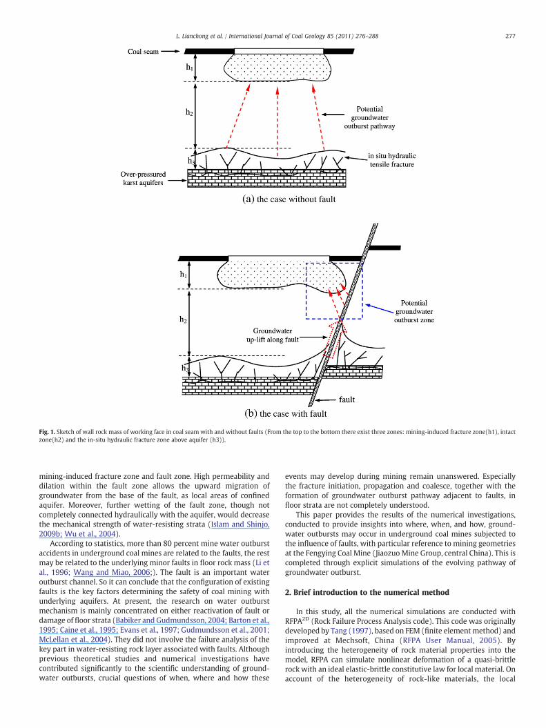
Fig. 1. Sketch of wall rock mass of working face in coal seam with and without faults (From the top to the bottom there exist three zones: mining-induced fracture zone(h1), intactzone(h2) and the in-situ hydraulic fracture zone above aquifer (h3)).
277L. Lianchong et al. / International Journal of Coal Geology 85 (2011) 276–288
mining-induced fracture zone and fault zone. High permeability anddilation within the fault zone allows the upward migration ofgroundwater from the base of the fault, as local areas of confinedaquifer. Moreover, further wetting of the fault zone, though notcompletely connected hydraulically with the aquifer, would decreasethe mechanical strength of water-resisting strata (Islam and Shinjo,2009b; Wu et al., 2004).
According to statistics, more than 80 percent mine water outburstaccidents in underground coal mines are related to the faults, the restmay be related to the underlying minor faults in floor rock mass (Li etal., 1996; Wang and Miao, 2006;). The fault is an important wateroutburst channel. So it can conclude that the configuration of existingfaults is the key factors determining the safety of coal mining withunderlying aquifers. At present, the research on water outburstmechanism is mainly concentrated on either reactivation of fault ordamage of floor strata (Babiker and Gudmundsson, 2004; Barton et al.,1995; Caine et al., 1995; Evans et al., 1997; Gudmundsson et al., 2001;McLellan et al., 2004). They did not involve the failure analysis of thekey part in water-resisting rock layer associated with faults. Althoughprevious theoretical studies and numerical investigations havecontributed significantly to the scientific understanding of ground-water outbursts, crucial questions of when, where and how these
events may develop during mining remain unanswered. Especiallythe fracture initiation, propagation and coalesce, together with theformation of groundwater outburst pathway adjacent to faults, infloor strata are not completely understood.
This paper provides the results of the numerical investigations,conducted to provide insights into where, when, and how, ground-water outbursts may occur in underground coal mines subjected tothe influence of faults, with particular reference to mining geometriesat the Fengying Coal Mine (Jiaozuo Mine Group, central China). This iscompleted through explicit simulations of the evolving pathway ofgroundwater outburst.
2. Brief introduction to the numerical method
In this study, all the numerical simulations are conducted withRFPA2D (Rock Failure Process Analysis code). This code was originallydeveloped by Tang (1997), based on FEM (finite elementmethod) andimproved at Mechsoft, China (RFPA User Manual, 2005). Byintroducing the heterogeneity of rock material properties into themodel, RFPA can simulate nonlinear deformation of a quasi-brittlerock with an ideal elastic-brittle constitutive law for local material. Onaccount of the heterogeneity of rock-like materials, the local
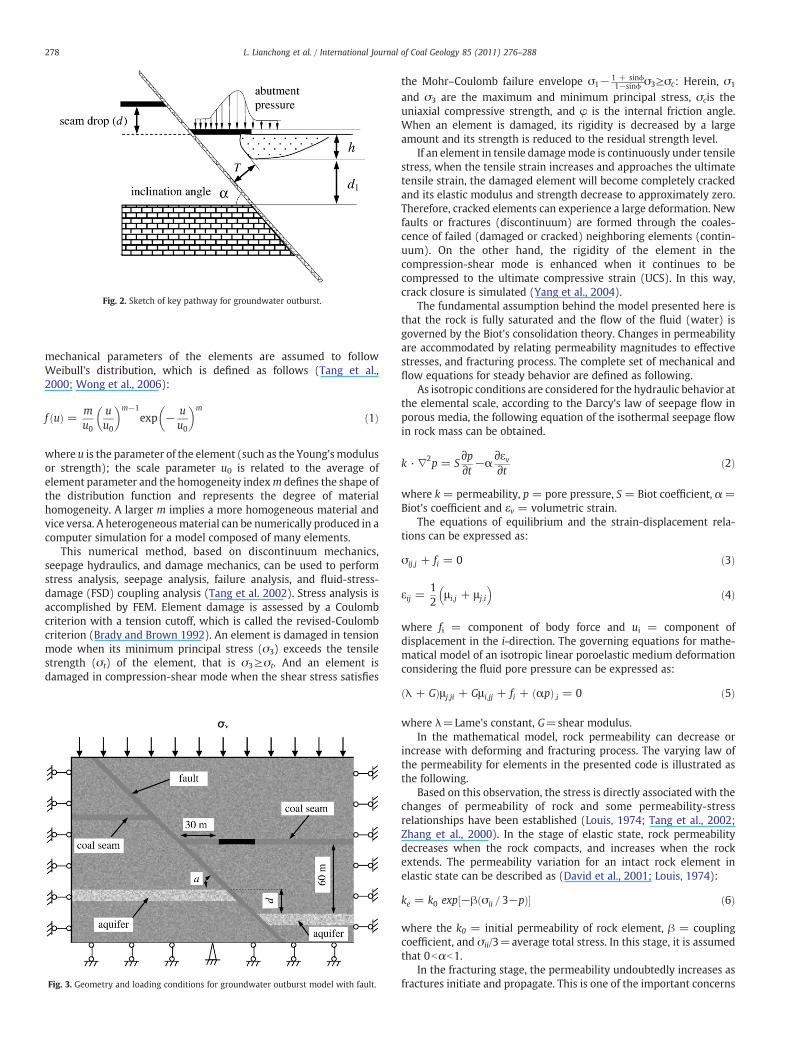
Fig. 2. Sketch of key pathway for groundwater outburst.
278 L. Lianchong et al. / International Journal of Coal Geology 85 (2011) 276–288
mechanical parameters of the elements are assumed to followWeibull's distribution, which is defined as follows (Tang et al.,2000; Wong et al., 2006):
f uð Þ = mu0
uu0
� �m−1exp − u
u0
� �m
ð1Þ
where u is the parameter of the element (such as the Young'smodulusor strength); the scale parameter u0 is related to the average ofelement parameter and the homogeneity indexm defines the shape ofthe distribution function and represents the degree of materialhomogeneity. A larger m implies a more homogeneous material andvice versa. A heterogeneousmaterial can be numerically produced in acomputer simulation for a model composed of many elements.
This numerical method, based on discontinuum mechanics,seepage hydraulics, and damage mechanics, can be used to performstress analysis, seepage analysis, failure analysis, and fluid-stress-damage (FSD) coupling analysis (Tang et al. 2002). Stress analysis isaccomplished by FEM. Element damage is assessed by a Coulombcriterion with a tension cutoff, which is called the revised-Coulombcriterion (Brady and Brown 1992). An element is damaged in tensionmode when its minimum principal stress (σ3) exceeds the tensilestrength (σt) of the element, that is σ3≥σt. And an element isdamaged in compression-shear mode when the shear stress satisfies
Fig. 3. Geometry and loading conditions for groundwater outburst model with fault.
the Mohr–Coulomb failure envelope σ1− 1 + sinϕ1−sinϕ σ3≥σc: Herein, σ1
and σ3 are the maximum and minimum principal stress, σcis theuniaxial compressive strength, and φ is the internal friction angle.When an element is damaged, its rigidity is decreased by a largeamount and its strength is reduced to the residual strength level.
If an element in tensile damagemode is continuously under tensilestress, when the tensile strain increases and approaches the ultimatetensile strain, the damaged element will become completely crackedand its elastic modulus and strength decrease to approximately zero.Therefore, cracked elements can experience a large deformation. Newfaults or fractures (discontinuum) are formed through the coales-cence of failed (damaged or cracked) neighboring elements (contin-uum). On the other hand, the rigidity of the element in thecompression-shear mode is enhanced when it continues to becompressed to the ultimate compressive strain (UCS). In this way,crack closure is simulated (Yang et al., 2004).
The fundamental assumption behind the model presented here isthat the rock is fully saturated and the flow of the fluid (water) isgoverned by the Biot's consolidation theory. Changes in permeabilityare accommodated by relating permeability magnitudes to effectivestresses, and fracturing process. The complete set of mechanical andflow equations for steady behavior are defined as following.
As isotropic conditions are considered for the hydraulic behavior atthe elemental scale, according to the Darcy's law of seepage flow inporous media, the following equation of the isothermal seepage flowin rock mass can be obtained.
k · ∇2p = S∂p∂t −α
∂εv∂t ð2Þ
where k = permeability, p = pore pressure, S = Biot coefficient, α =Biot's coefficient and εv = volumetric strain.
The equations of equilibrium and the strain-displacement rela-tions can be expressed as:
σij;j + fi = 0 ð3Þ
εij =12
μ i;j + μ j;i
� �ð4Þ
where fi = component of body force and ui = component ofdisplacement in the i-direction. The governing equations for mathe-matical model of an isotropic linear poroelastic medium deformationconsidering the fluid pore pressure can be expressed as:
λ + Gð Þμ j;ji + Gμ i;jj + fi + αpð Þ;i = 0 ð5Þ
where λ=Lame's constant, G=shear modulus.In the mathematical model, rock permeability can decrease or
increase with deforming and fracturing process. The varying law ofthe permeability for elements in the presented code is illustrated asthe following.
Based on this observation, the stress is directly associated with thechanges of permeability of rock and some permeability-stressrelationships have been established (Louis, 1974; Tang et al., 2002;Zhang et al., 2000). In the stage of elastic state, rock permeabilitydecreases when the rock compacts, and increases when the rockextends. The permeability variation for an intact rock element inelastic state can be described as (David et al., 2001; Louis, 1974):
ke = k0 exp −β σii = 3−pð Þ½ � ð6Þ
where the k0 = initial permeability of rock element, β = couplingcoefficient, and σii/3=average total stress. In this stage, it is assumedthat 0bαb1.
In the fracturing stage, the permeability undoubtedly increases asfractures initiate and propagate. This is one of the important concerns
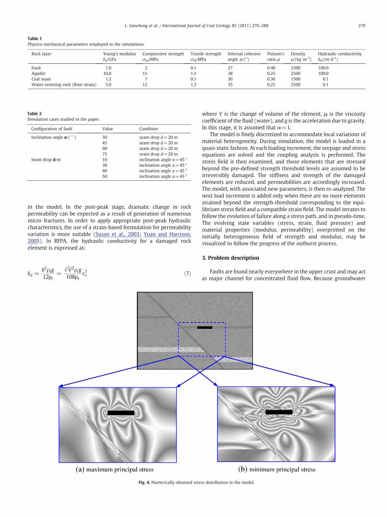
Table 1Physico-mechanical parameters employed in the simulations.
Rock layer Young's modulusE0/GPa
Compressive strengthσc0/MPa
Tensile strengthσt0/MPa
Internal cohesiveangle ϕ/(°)
Poisson'sratio μ
Densityρ/(kg⋅m-3)
Hydraulic conductivityk0/(m⋅d-1)
Fault 1.0 2 0.1 27 0.40 2300 100.0Aquifer 10.0 15 1.5 38 0.25 2500 100.0Coal seam 1.2 7 0.1 30 0.30 1500 0.1Water-resisting rock (floor strata) 5.0 12 1.2 35 0.25 2500 0.1
Table 2Simulation cases studied in the paper.
Configuration of fault Value Condition
Inclination angle a/( ° ) 30 seam drop d=20 m45 seam drop d=20 m60 seam drop d=20 m75 seam drop d=20 m
Seam drop d/m 10 inclination angle a=45 °30 inclination angle a=45 °40 inclination angle a=45 °50 inclination angle a=45 °
279L. Lianchong et al. / International Journal of Coal Geology 85 (2011) 276–288
in the model. In the post-peak stage, dramatic change in rockpermeability can be expected as a result of generation of numerousmicro fractures. In order to apply appropriate post-peak hydrauliccharacteristics, the use of a strain-based formulation for permeabilityvariation is more suitable (Susan et al., 2003; Yuan and Harrison,2005). In RFPA, the hydraulic conductivity for a damaged rockelement is expressed as:
kd =b2ρlg12μ l
=
ffiffiffiffiffiffiV23
pρlg
108μ lε2v ð7Þ
Fig. 4. Numerically obtained stre
where V is the change of volume of the element, μl is the viscositycoefficient of the fluid (water), and g is the acceleration due to gravity.In this stage, it is assumed that α=1.
The model is finely discretized to accommodate local variations ofmaterial heterogeneity. During simulation, the model is loaded in aquasi-static fashion. At each loading increment, the seepage and stressequations are solved and the coupling analysis is performed. Thestress field is then examined, and those elements that are stressedbeyond the pre-defined strength threshold levels are assumed to beirreversibly damaged. The stiffness and strength of the damagedelements are reduced, and permeabilities are accordingly increased.The model, with associated new parameters, is then re-analyzed. Thenext load increment is added only when there are no more elementsstrained beyond the strength-threshold corresponding to the equi-librium stress field and a compatible strain field. The model iterates tofollow the evolution of failure along a stress path, and in pseudo-time.The evolving state variables (stress, strain, fluid pressure) andmaterial properties (modulus, permeability) overprinted on theinitially heterogeneous field of strength and modulus, may bevisualized to follow the progress of the outburst process.
3. Problem description
Faults are found nearly everywhere in the upper crust and may actas major channel for concentrated fluid flow. Because groundwater
ss distribution in the model.
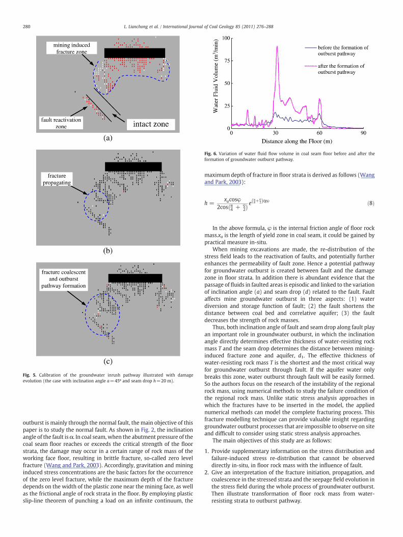
Fig. 5. Calibration of the groundwater inrush pathway illustrated with damageevolution (the case with inclination angle a=45º and seam drop h=20 m).
Fig. 6. Variation of water fluid flow volume in coal seam floor before and after theformation of groundwater outburst pathway.
280 L. Lianchong et al. / International Journal of Coal Geology 85 (2011) 276–288
outburst is mainly through the normal fault, the main objective of thispaper is to study the normal fault. As shown in Fig. 2, the inclinationangle of the fault is α. In coal seam, when the abutment pressure of thecoal seam floor reaches or exceeds the critical strength of the floorstrata, the damage may occur in a certain range of rock mass of theworking face floor, resulting in brittle fracture, so-called zero levelfracture (Wang and Park, 2003). Accordingly, gravitation and mininginduced stress concentrations are the basic factors for the occurrenceof the zero level fracture, while the maximum depth of the fracturedepends on the width of the plastic zone near the mining face, as wellas the frictional angle of rock strata in the floor. By employing plasticslip-line theorem of punching a load on an infinite continuum, the
maximum depth of fracture in floor strata is derived as follows (Wangand Park, 2003):
h =xacosφ
2cos π4 + φ
2
� � e π4+
φ2ð Þtgφ ð8Þ
In the above formula, φ is the internal friction angle of floor rockmass.xa is the length of yield zone in coal seam, it could be gained bypractical measure in-situ.
When mining excavations are made, the re-distribution of thestress field leads to the reactivation of faults, and potentially furtherenhances the permeability of fault zone. Hence a potential pathwayfor groundwater outburst is created between fault and the damagezone in floor strata. In addition there is abundant evidence that thepassage of fluids in faulted areas is episodic and linked to the variationof inclination angle (a) and seam drop (d) related to the fault. Faultaffects mine groundwater outburst in three aspects: (1) waterdiversion and storage function of fault; (2) the fault shortens thedistance between coal bed and correlative aquifer; (3) the faultdecreases the strength of rock masses.
Thus, both inclination angle of fault and seam drop along fault playan important role in groundwater outburst, in which the inclinationangle directly determines effective thickness of water-resisting rockmass T and the seam drop determines the distance between mining-induced fracture zone and aquifer, d1. The effective thickness ofwater-resisting rock mass T is the shortest and the most critical wayfor groundwater outburst through fault. If the aquifer water onlybreaks this zone, water outburst through fault will be easily formed.So the authors focus on the research of the instability of the regionalrock mass, using numerical methods to study the failure condition ofthe regional rock mass. Unlike static stress analysis approaches inwhich the fractures have to be inserted in the model, the appliednumerical methods can model the complete fracturing process. Thisfracture modelling technique can provide valuable insight regardinggroundwater outburst processes that are impossible to observe on siteand difficult to consider using static stress analysis approaches.
The main objectives of this study are as follows:
1. Provide supplementary information on the stress distribution andfailure-induced stress re-distribution that cannot be observeddirectly in-situ, in floor rock mass with the influence of fault.
2. Give an interpretation of the fracture initiation, propagation, andcoalescence in the stressed strata and the seepage field evolution inthe stress field during the whole process of groundwater outburst.Then illustrate transformation of floor rock mass from water-resisting strata to outburst pathway.
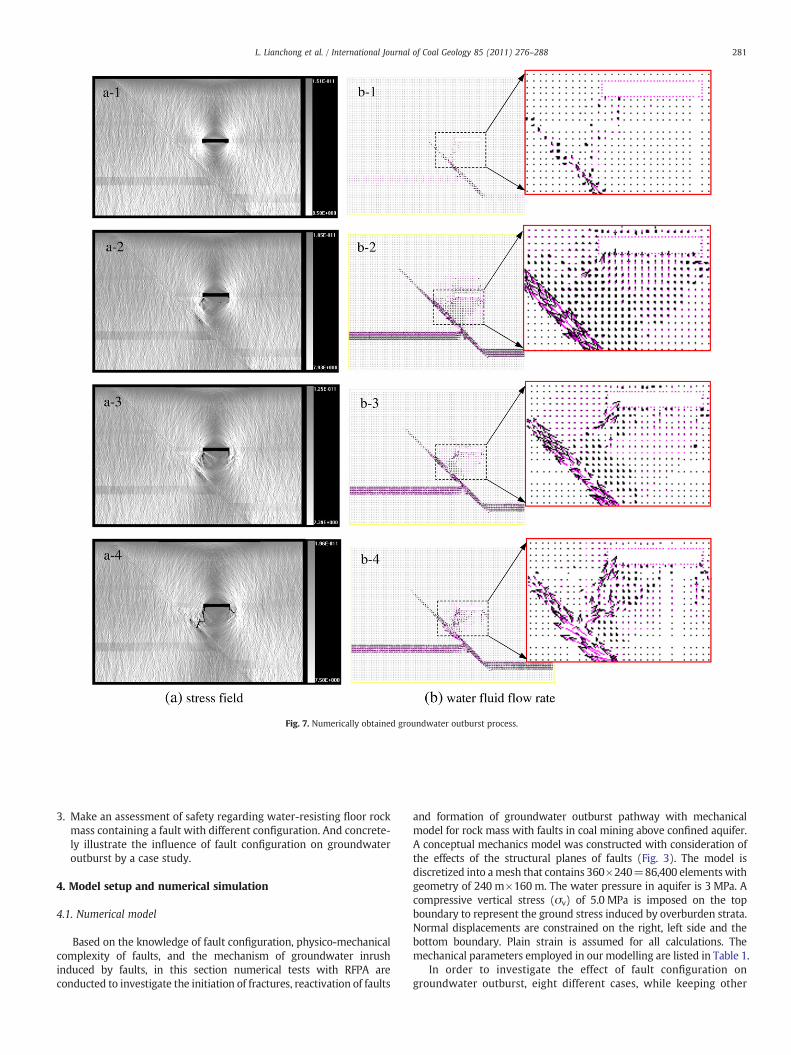
Fig. 7. Numerically obtained groundwater outburst process.
281L. Lianchong et al. / International Journal of Coal Geology 85 (2011) 276–288
3. Make an assessment of safety regarding water-resisting floor rockmass containing a fault with different configuration. And concrete-ly illustrate the influence of fault configuration on groundwateroutburst by a case study.
4. Model setup and numerical simulation
4.1. Numerical model
Based on the knowledge of fault configuration, physico-mechanicalcomplexity of faults, and the mechanism of groundwater inrushinduced by faults, in this section numerical tests with RFPA areconducted to investigate the initiation of fractures, reactivation of faults
and formation of groundwater outburst pathway with mechanicalmodel for rock mass with faults in coal mining above confined aquifer.A conceptual mechanics model was constructed with consideration ofthe effects of the structural planes of faults (Fig. 3). The model isdiscretized into amesh that contains 360×240=86,400 elements withgeometry of 240 m×160 m. The water pressure in aquifer is 3 MPa. Acompressive vertical stress (σv) of 5.0 MPa is imposed on the topboundary to represent the ground stress induced by overburden strata.Normal displacements are constrained on the right, left side and thebottom boundary. Plain strain is assumed for all calculations. Themechanical parameters employed in our modelling are listed in Table 1.
In order to investigate the effect of fault configuration ongroundwater outburst, eight different cases, while keeping other
y = 0.4637e0.0303x
0
1
2
3
4
5
15 30 45 60 75 90
Inclination angle /(°)
Safe
ty f
acto
r
(a)
y = 2.1523e-0.0137x
0
1
2
3
4
5
0 20 40 60
Seam drop (m)
Safe
ty f
acto
r
(b)
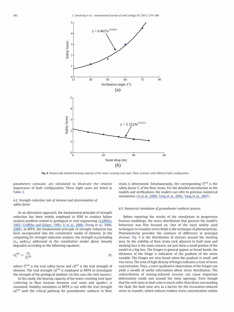
Fig. 8. Numerically obtained bearing capacity of the water-resisting rock layer (floor stratum) with different fault configuration.
282 L. Lianchong et al. / International Journal of Coal Geology 85 (2011) 276–288
parameters constant, are simulated to illustrate the relativeimportance of fault configuration. These eight cases are listed inTable 2.
4.2. Strength reduction rule of element and determination ofsafety factor
As an alternative approach, the fundamental principle of strengthreduction has been widely employed in FEM to conduct failureanalysis problem related to geological or rock engineering (Griffiths,1982; Griffiths and Kidger, 1995; Li et al., 2006; Zheng et al., 2006,2008). In RFPA, the fundamental principle of strength reduction hasbeen incorporated into the constitutive model of element. In thecomputing for strength reduction analysis, the strength σ0(includingσc0 andσt0) addressed in the constitutive model above linearlydegraded according to the following equation:
σtrial0 =
σ0
Ftrials
ð9Þ
where Fstrial is the trial safety factor and σ0
trial is the trial strength ofelement. The trial strength σ0
trial is employed in RFPA to investigatethe strength of the geological medium (in this case, the rock masses).
In this study, the bearing capacity of the water-resisting rock layer(referring to floor stratum between coal seam and aquifer) isexamined. Stability simulation in RFPA is run with the trial strengthσ0
trial until the critical pathway for groundwater outburst in floor
strata is determined. Simultaneously, the corresponding Fstrial is the
safety factor Fs of the floor strata. For the detailed introduction to themodels and verifications, the readers can refer to previous numericalsimulations (Li et al., 2006; Tang et al., 2002; Yang et al., 2007).
4.3. Numerical simulation of groundwater outburst process
Before reporting the results of the simulations in progressivefracture modelings, the stress distribution that governs the model'sbehaviour was first focused on. One of the most widely usedtechniques to visualize stress fields is the technique of photoelasticity.Photoelasticity provides the contours of difference in principalstresses. Fig. 4 is the distribution of stresses around the workingarea. As the stability of floor strata rock adjacent to fault zone andworking face is the main concern, we just show a small portion of themodel in a big box. The fringes in general appear as broad bands, thethickness of the fringe is indicative of the gradient of the stressvariable. The fringes are very broad when the gradient is small, andvice versa. The zone of high density of fringes indicates a zone of stressconcentration. Thus, a mere qualitative observation of the fringes canyield a wealth of useful information about stress distribution. Theredistribution of mining-induced stresses can cause importantdeformation inside and around the mine openings. Even thoughthat the rock mass in fault zone is much softer than those surroundingthe fault, the fault zone acts as a barrier for the excavation-inducedstress to transfer, which induces evident stress concentration within
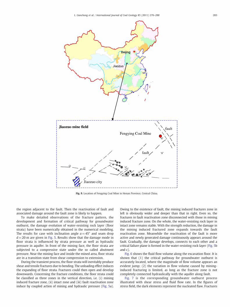
Fig. 9. Location of Fengying Coal Mine in Henan Province, Central China.
283L. Lianchong et al. / International Journal of Coal Geology 85 (2011) 276–288
the region adjacent to the fault. Then the reactivation of fault andassociated damage around the fault zone is likely to happen.
To make detailed observations of the fracture pattern, thedevelopment and formation of critical pathway for groundwateroutburst, the damage evolution of water-resisting rock layer (floorstrata) have been numerically obtained in the numerical modeling.The results for case with inclination angle a=45° and seam dropd=20 m are given in Fig. 5. Results show that the damage mode infloor strata is influenced by strata pressure as well as hydraulicpressure in aquifer. In front of the mining face, the floor strata aresubjected to a compressive state under the so called abutmentpressure. Near the mining face and inside the mined area, floor strataare in a transition state from shear compression to extension.
During the transient process, the floor strata will inevitably produceshear and tensile fractures due to bending. The unloading effect inducesthe expanding of floor strata. Fractures could then open and developdownwards. Concerning the fracture conditions, the floor strata couldbe classified as three zones in the vertical direction, i.e. (i) mininginduced fracture zone, (ii) intact zone and (iii) fault reactivation zoneinduce by coupled action of mining and hydraulic pressure (Fig. 5a).
Owing to the existence of fault, the mining induced fractures zone inleft is obviously wider and deeper than that in right. Even so, thefractures in fault reactivation zone disconnected with those in mininginduced fracture zone. On the whole, the water-resisting rock layer inintact zone remains stable. With the strength reduction, the damage inthe mining induced fractured zone expands towards the faultreactivation zone. Meanwhile the reactivation of the fault is moreactive and newly generated damage continuously appears around thefault. Gradually, the damage develops, connects to each other and acritical failure plane is formed in the water-resisting rock layer (Fig. 5band c).
Fig. 6 shows the fluid flow volume along the excavation floor. It isshown that (1) the critical pathway for groundwater outburst isaccurately located, where the magnitude of flow volume appears anevident jump; (2) the variation in flow volume caused by mining-induced fracturing is limited, as long as the fracture zone is notcompletely connected hydraulically with the aquifer along fault.
Fig. 7 is the corresponding groundwater outburst processillustrated with shear stress and fluid flow rate. In the figures ofstress field, the dark elements represent the nucleated flaw. Fractures
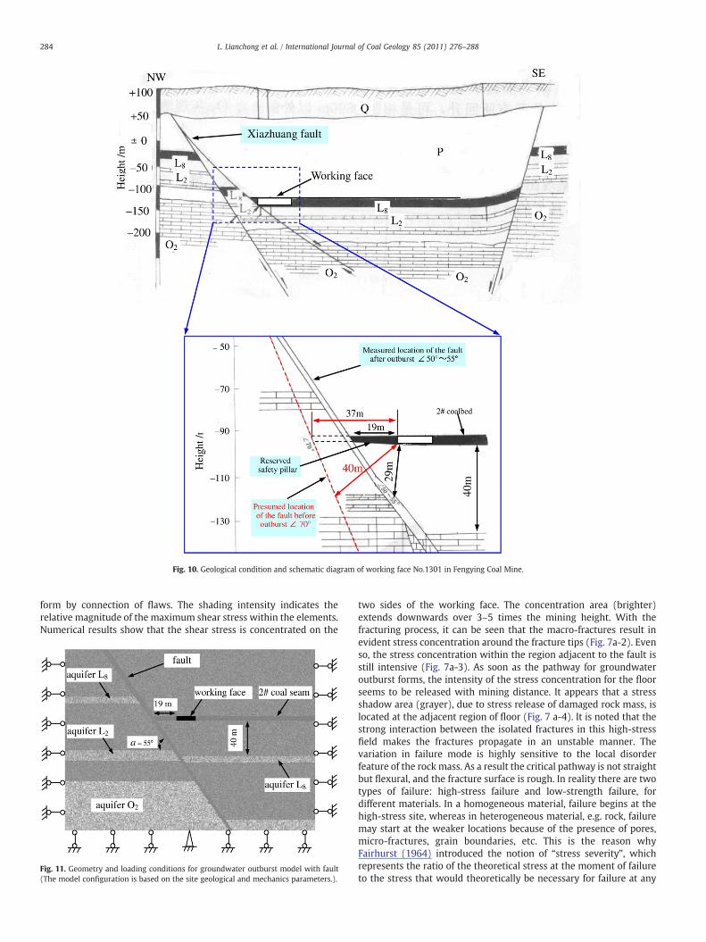
Fig. 10. Geological condition and schematic diagram of working face No.1301 in Fengying Coal Mine.
284 L. Lianchong et al. / International Journal of Coal Geology 85 (2011) 276–288
form by connection of flaws. The shading intensity indicates therelative magnitude of the maximum shear stress within the elements.Numerical results show that the shear stress is concentrated on the
Fig. 11. Geometry and loading conditions for groundwater outburst model with fault(The model configuration is based on the site geological and mechanics parameters.).
two sides of the working face. The concentration area (brighter)extends downwards over 3–5 times the mining height. With thefracturing process, it can be seen that the macro-fractures result inevident stress concentration around the fracture tips (Fig. 7a-2). Evenso, the stress concentration within the region adjacent to the fault isstill intensive (Fig. 7a-3). As soon as the pathway for groundwateroutburst forms, the intensity of the stress concentration for the floorseems to be released with mining distance. It appears that a stressshadow area (grayer), due to stress release of damaged rock mass, islocated at the adjacent region of floor (Fig. 7 a-4). It is noted that thestrong interaction between the isolated fractures in this high-stressfield makes the fractures propagate in an unstable manner. Thevariation in failure mode is highly sensitive to the local disorderfeature of the rock mass. As a result the critical pathway is not straightbut flexural, and the fracture surface is rough. In reality there are twotypes of failure: high-stress failure and low-strength failure, fordifferent materials. In a homogeneous material, failure begins at thehigh-stress site, whereas in heterogeneous material, e.g. rock, failuremay start at the weaker locations because of the presence of pores,micro-fractures, grain boundaries, etc. This is the reason whyFairhurst (1964) introduced the notion of “stress severity”, whichrepresents the ratio of the theoretical stress at the moment of failureto the stress that would theoretically be necessary for failure at any
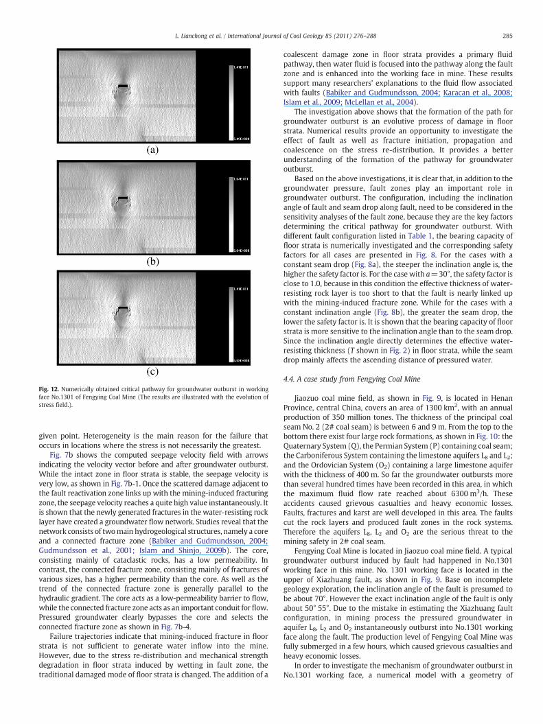
Fig. 12. Numerically obtained critical pathway for groundwater outburst in workingface No.1301 of Fengying Coal Mine (The results are illustrated with the evolution ofstress field.).
285L. Lianchong et al. / International Journal of Coal Geology 85 (2011) 276–288
given point. Heterogeneity is the main reason for the failure thatoccurs in locations where the stress is not necessarily the greatest.
Fig. 7b shows the computed seepage velocity field with arrowsindicating the velocity vector before and after groundwater outburst.While the intact zone in floor strata is stable, the seepage velocity isvery low, as shown in Fig. 7b-1. Once the scattered damage adjacent tothe fault reactivation zone links up with the mining-induced fracturingzone, the seepage velocity reaches a quite high value instantaneously. Itis shown that the newly generated fractures in the water-resisting rocklayer have created a groundwater flow network. Studies reveal that thenetwork consists of twomain hydrogeological structures, namely a coreand a connected fracture zone (Babiker and Gudmundsson, 2004;Gudmundsson et al., 2001; Islam and Shinjo, 2009b). The core,consisting mainly of cataclastic rocks, has a low permeability. Incontrast, the connected fracture zone, consisting mainly of fractures ofvarious sizes, has a higher permeability than the core. As well as thetrend of the connected fracture zone is generally parallel to thehydraulic gradient. The core acts as a low-permeability barrier to flow,while the connected fracture zone acts as an important conduit for flow.Pressured groundwater clearly bypasses the core and selects theconnected fracture zone as shown in Fig. 7b-4.
Failure trajectories indicate that mining-induced fracture in floorstrata is not sufficient to generate water inflow into the mine.However, due to the stress re-distribution and mechanical strengthdegradation in floor strata induced by wetting in fault zone, thetraditional damaged mode of floor strata is changed. The addition of a
coalescent damage zone in floor strata provides a primary fluidpathway, then water fluid is focused into the pathway along the faultzone and is enhanced into the working face in mine. These resultssupport many researchers’ explanations to the fluid flow associatedwith faults (Babiker and Gudmundsson, 2004; Karacan et al., 2008;Islam et al., 2009; McLellan et al., 2004).
The investigation above shows that the formation of the path forgroundwater outburst is an evolutive process of damage in floorstrata. Numerical results provide an opportunity to investigate theeffect of fault as well as fracture initiation, propagation andcoalescence on the stress re-distribution. It provides a betterunderstanding of the formation of the pathway for groundwateroutburst.
Based on the above investigations, it is clear that, in addition to thegroundwater pressure, fault zones play an important role ingroundwater outburst. The configuration, including the inclinationangle of fault and seam drop along fault, need to be considered in thesensitivity analyses of the fault zone, because they are the key factorsdetermining the critical pathway for groundwater outburst. Withdifferent fault configuration listed in Table 1, the bearing capacity offloor strata is numerically investigated and the corresponding safetyfactors for all cases are presented in Fig. 8. For the cases with aconstant seam drop (Fig. 8a), the steeper the inclination angle is, thehigher the safety factor is. For the case with a=30°, the safety factor isclose to 1.0, because in this condition the effective thickness of water-resisting rock layer is too short to that the fault is nearly linked upwith the mining-induced fracture zone. While for the cases with aconstant inclination angle (Fig. 8b), the greater the seam drop, thelower the safety factor is. It is shown that the bearing capacity of floorstrata is more sensitive to the inclination angle than to the seam drop.Since the inclination angle directly determines the effective water-resisting thickness (T shown in Fig. 2) in floor strata, while the seamdrop mainly affects the ascending distance of pressured water.
4.4. A case study from Fengying Coal Mine
Jiaozuo coal mine field, as shown in Fig. 9, is located in HenanProvince, central China, covers an area of 1300 km2, with an annualproduction of 350 million tones. The thickness of the principal coalseam No. 2 (2# coal seam) is between 6 and 9 m. From the top to thebottom there exist four large rock formations, as shown in Fig. 10: theQuaternary System (Q), the Permian System (P) containing coal seam;the Carboniferous System containing the limestone aquifers L8 and L2;and the Ordovician System (O2) containing a large limestone aquiferwith the thickness of 400 m. So far the groundwater outbursts morethan several hundred times have been recorded in this area, in whichthe maximum fluid flow rate reached about 6300 m3/h. Theseaccidents caused grievous casualties and heavy economic losses.Faults, fractures and karst are well developed in this area. The faultscut the rock layers and produced fault zones in the rock systems.Therefore the aquifers L8, L2 and O2 are the serious threat to themining safety in 2# coal seam.
Fengying Coal Mine is located in Jiaozuo coal mine field. A typicalgroundwater outburst induced by fault had happened in No.1301working face in this mine. No. 1301 working face is located in theupper of Xiazhuang fault, as shown in Fig. 9. Base on incompletegeology exploration, the inclination angle of the fault is presumed tobe about 70°. However the exact inclination angle of the fault is onlyabout 50° 55°. Due to the mistake in estimating the Xiazhuang faultconfiguration, in mining process the pressured groundwater inaquifer L8, L2 and O2 instantaneously outburst into No.1301 workingface along the fault. The production level of Fengying Coal Mine wasfully submerged in a few hours, which caused grievous casualties andheavy economic losses.
In order to investigate the mechanism of groundwater outburst inNo.1301 working face, a numerical model with a geometry of
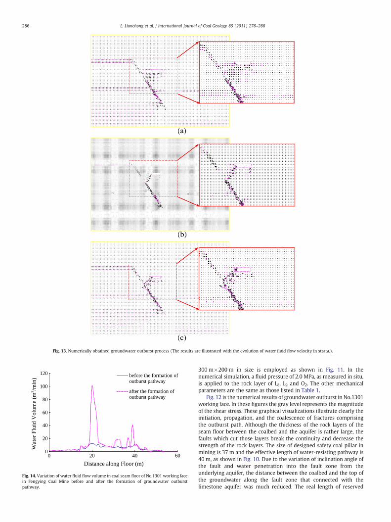
Fig. 13. Numerically obtained groundwater outburst process (The results are illustrated with the evolution of water fluid flow velocity in strata.).
0
20
40
60
80
100
120
0 20 40 60
Distance along Floor (m)
before the formation ofoutburst pathway
after the formation ofoutburst pathway
Wat
er F
luid
Vol
ume
(m3 /
min
)
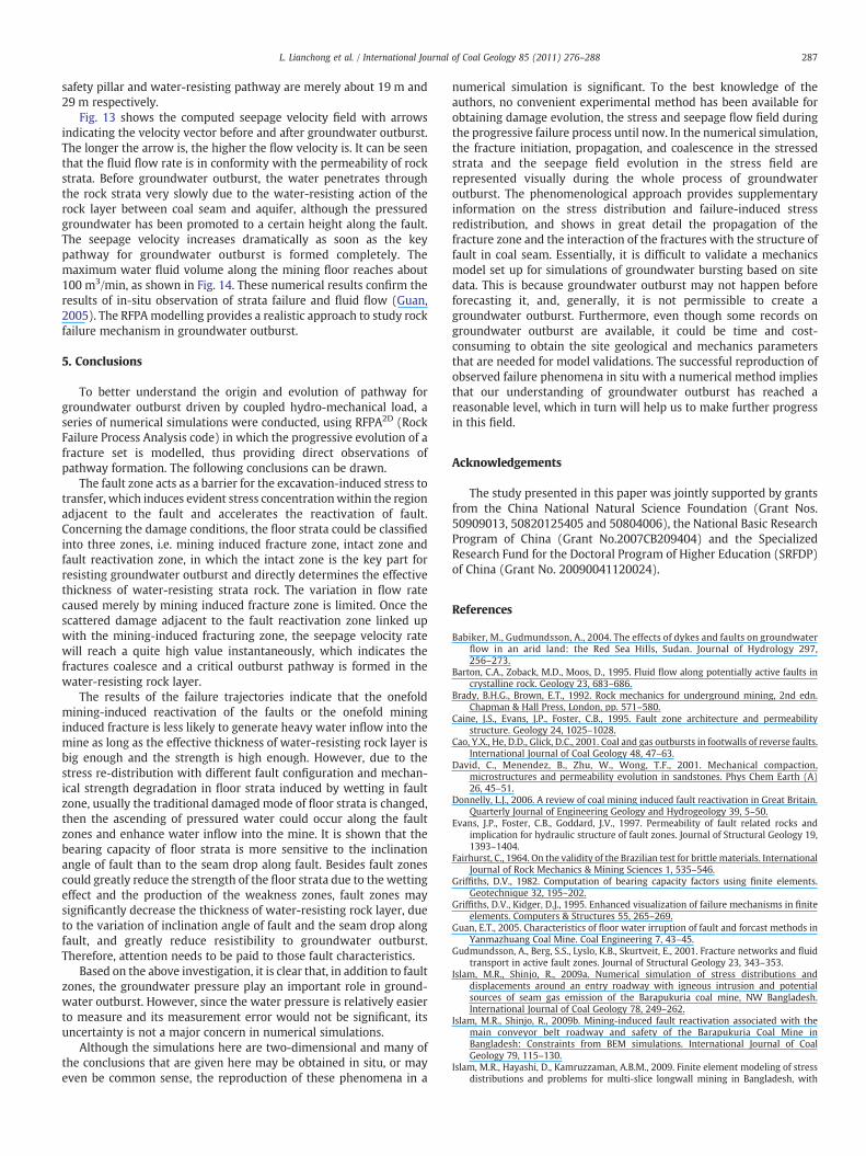
Fig. 14. Variation of water fluid flow volume in coal seam floor of No.1301 working facein Fengying Coal Mine before and after the formation of groundwater outburstpathway.
286 L. Lianchong et al. / International Journal of Coal Geology 85 (2011) 276–288
300 m×200 m in size is employed as shown in Fig. 11. In thenumerical simulation, a fluid pressure of 2.0 MPa, as measured in situ,is applied to the rock layer of L8, L2 and O2. The other mechanicalparameters are the same as those listed in Table 1.
Fig. 12 is the numerical results of groundwater outburst in No.1301working face. In these figures the gray level represents the magnitudeof the shear stress. These graphical visualizations illustrate clearly theinitiation, propagation, and the coalescence of fractures comprisingthe outburst path. Although the thickness of the rock layers of theseam floor between the coalbed and the aquifer is rather large, thefaults which cut those layers break the continuity and decrease thestrength of the rock layers. The size of designed safety coal pillar inmining is 37 m and the effective length of water-resisting pathway is40 m, as shown in Fig. 10. Due to the variation of inclination angle ofthe fault and water penetration into the fault zone from theunderlying aquifer, the distance between the coalbed and the top ofthe groundwater along the fault zone that connected with thelimestone aquifer was much reduced. The real length of reserved
287L. Lianchong et al. / International Journal of Coal Geology 85 (2011) 276–288
safety pillar and water-resisting pathway are merely about 19 m and29 m respectively.
Fig. 13 shows the computed seepage velocity field with arrowsindicating the velocity vector before and after groundwater outburst.The longer the arrow is, the higher the flow velocity is. It can be seenthat the fluid flow rate is in conformity with the permeability of rockstrata. Before groundwater outburst, the water penetrates throughthe rock strata very slowly due to the water-resisting action of therock layer between coal seam and aquifer, although the pressuredgroundwater has been promoted to a certain height along the fault.The seepage velocity increases dramatically as soon as the keypathway for groundwater outburst is formed completely. Themaximum water fluid volume along the mining floor reaches about100 m3/min, as shown in Fig. 14. These numerical results confirm theresults of in-situ observation of strata failure and fluid flow (Guan,2005). The RFPAmodelling provides a realistic approach to study rockfailure mechanism in groundwater outburst.
5. Conclusions
To better understand the origin and evolution of pathway forgroundwater outburst driven by coupled hydro-mechanical load, aseries of numerical simulations were conducted, using RFPA2D (RockFailure Process Analysis code) in which the progressive evolution of afracture set is modelled, thus providing direct observations ofpathway formation. The following conclusions can be drawn.
The fault zone acts as a barrier for the excavation-induced stress totransfer, which induces evident stress concentrationwithin the regionadjacent to the fault and accelerates the reactivation of fault.Concerning the damage conditions, the floor strata could be classifiedinto three zones, i.e. mining induced fracture zone, intact zone andfault reactivation zone, in which the intact zone is the key part forresisting groundwater outburst and directly determines the effectivethickness of water-resisting strata rock. The variation in flow ratecaused merely by mining induced fracture zone is limited. Once thescattered damage adjacent to the fault reactivation zone linked upwith the mining-induced fracturing zone, the seepage velocity ratewill reach a quite high value instantaneously, which indicates thefractures coalesce and a critical outburst pathway is formed in thewater-resisting rock layer.
The results of the failure trajectories indicate that the onefoldmining-induced reactivation of the faults or the onefold mininginduced fracture is less likely to generate heavy water inflow into themine as long as the effective thickness of water-resisting rock layer isbig enough and the strength is high enough. However, due to thestress re-distribution with different fault configuration and mechan-ical strength degradation in floor strata induced by wetting in faultzone, usually the traditional damaged mode of floor strata is changed,then the ascending of pressured water could occur along the faultzones and enhance water inflow into the mine. It is shown that thebearing capacity of floor strata is more sensitive to the inclinationangle of fault than to the seam drop along fault. Besides fault zonescould greatly reduce the strength of the floor strata due to the wettingeffect and the production of the weakness zones, fault zones maysignificantly decrease the thickness of water-resisting rock layer, dueto the variation of inclination angle of fault and the seam drop alongfault, and greatly reduce resistibility to groundwater outburst.Therefore, attention needs to be paid to those fault characteristics.
Based on the above investigation, it is clear that, in addition to faultzones, the groundwater pressure play an important role in ground-water outburst. However, since the water pressure is relatively easierto measure and its measurement error would not be significant, itsuncertainty is not a major concern in numerical simulations.
Although the simulations here are two-dimensional and many ofthe conclusions that are given here may be obtained in situ, or mayeven be common sense, the reproduction of these phenomena in a
numerical simulation is significant. To the best knowledge of theauthors, no convenient experimental method has been available forobtaining damage evolution, the stress and seepage flow field duringthe progressive failure process until now. In the numerical simulation,the fracture initiation, propagation, and coalescence in the stressedstrata and the seepage field evolution in the stress field arerepresented visually during the whole process of groundwateroutburst. The phenomenological approach provides supplementaryinformation on the stress distribution and failure-induced stressredistribution, and shows in great detail the propagation of thefracture zone and the interaction of the fractures with the structure offault in coal seam. Essentially, it is difficult to validate a mechanicsmodel set up for simulations of groundwater bursting based on sitedata. This is because groundwater outburst may not happen beforeforecasting it, and, generally, it is not permissible to create agroundwater outburst. Furthermore, even though some records ongroundwater outburst are available, it could be time and cost-consuming to obtain the site geological and mechanics parametersthat are needed for model validations. The successful reproduction ofobserved failure phenomena in situ with a numerical method impliesthat our understanding of groundwater outburst has reached areasonable level, which in turn will help us to make further progressin this field.
Acknowledgements
The study presented in this paper was jointly supported by grantsfrom the China National Natural Science Foundation (Grant Nos.50909013, 50820125405 and 50804006), the National Basic ResearchProgram of China (Grant No.2007CB209404) and the SpecializedResearch Fund for the Doctoral Program of Higher Education (SRFDP)of China (Grant No. 20090041120024).
References
Babiker, M., Gudmundsson, A., 2004. The effects of dykes and faults on groundwaterflow in an arid land: the Red Sea Hills, Sudan. Journal of Hydrology 297,256–273.
Barton, C.A., Zoback, M.D., Moos, D., 1995. Fluid flow along potentially active faults incrystalline rock. Geology 23, 683–686.
Brady, B.H.G., Brown, E.T., 1992. Rock mechanics for underground mining, 2nd edn.Chapman & Hall Press, London, pp. 571–580.
Caine, J.S., Evans, J.P., Foster, C.B., 1995. Fault zone architecture and permeabilitystructure. Geology 24, 1025–1028.
Cao, Y.X., He, D.D., Glick, D.C., 2001. Coal and gas outbursts in footwalls of reverse faults.International Journal of Coal Geology 48, 47–63.
David, C., Menendez, B., Zhu, W., Wong, T.F., 2001. Mechanical compaction,microstructures and permeability evolution in sandstones. Phys Chem Earth (A)26, 45–51.
Donnelly, L.J., 2006. A review of coal mining induced fault reactivation in Great Britain.Quarterly Journal of Engineering Geology and Hydrogeology 39, 5–50.
Evans, J.P., Foster, C.B., Goddard, J.V., 1997. Permeability of fault related rocks andimplication for hydraulic structure of fault zones. Journal of Structural Geology 19,1393–1404.
Fairhurst, C., 1964. On the validity of the Brazilian test for brittle materials. InternationalJournal of Rock Mechanics & Mining Sciences 1, 535–546.
Griffiths, D.V., 1982. Computation of bearing capacity factors using finite elements.Geotechnique 32, 195–202.
Griffiths, D.V., Kidger, D.J., 1995. Enhanced visualization of failure mechanisms in finiteelements. Computers & Structures 55, 265–269.
Guan, E.T., 2005. Characteristics of floor water irruption of fault and forcast methods inYanmazhuang Coal Mine. Coal Engineering 7, 43–45.
Gudmundsson, A., Berg, S.S., Lyslo, K.B., Skurtveit, E., 2001. Fracture networks and fluidtransport in active fault zones. Journal of Structural Geology 23, 343–353.
Islam, M.R., Shinjo, R., 2009a. Numerical simulation of stress distributions anddisplacements around an entry roadway with igneous intrusion and potentialsources of seam gas emission of the Barapukuria coal mine, NW Bangladesh.International Journal of Coal Geology 78, 249–262.
Islam, M.R., Shinjo, R., 2009b. Mining-induced fault reactivation associated with themain conveyor belt roadway and safety of the Barapukuria Coal Mine inBangladesh: Constraints from BEM simulations. International Journal of CoalGeology 79, 115–130.
Islam, M.R., Hayashi, D., Kamruzzaman, A.B.M., 2009. Finite element modeling of stressdistributions and problems for multi-slice longwall mining in Bangladesh, with
288 L. Lianchong et al. / International Journal of Coal Geology 85 (2011) 276–288
special reference to the Barapukuria coal mine. International Journal of CoalGeology 78, 91–109.
Karacan, C.Ö., Esterhuizen, G.S., Schatzel, S.J., Diamond, W.P., 2007. Reservoirsimulation-based modeling for characterizing longwall methane emissionsand gob gas venthole production. International Journal of Coal Geology 71,225–245.
Karacan, C.Ö., Ulery, J.P., Goodman, G.V.R., 2008. A numerical evaluation on the effectsof impermeable faults on degasification efficiency and methane emissions duringunderground coal mining. International Journal of Coal Geology 75, 195–203.
Li, L.J., Qian, M.G., Li, S.G., 1996. Analysis of water inrush induced by faults. Journal ofChina Coal Society 21, 119–123.
Li, L.C., Tang, C.A., Li, C.W., Zhu, W.C., 2006. Slope stability analysis by SRM-based rockfailure process analysis. Geomechanics and Geoengineering 1, 51–62.
Louis, C., 1974. Rock Hydroulics. In: Muller, L. (Ed.), Rock Mechanics. Springer, NewYork, pp. 300–387.
McLellan, J.G., Oliver, N.H.S., Schaubs, P.M., 2004. Fluid flow in extensional environ-ments; numerical modelling with an application to Hamersley iron ores. Journal ofStructural Geology 26, 1157–1171.
Oda, M.T., Takemura, A., Aoki, T., 2002. Damage growth and permeability change intriaxial compression tests of Inada granite. Mechanics of Materials 34, 313–331.
RFPA User Manual, 2005. Dalian Mechsoft Co., Ltd. Dalian, China.Schulze, O., Popp, T., Kern, H., 2001. Development of damage and permeability in
deforming rock salt. Engineering Geology 61, 163–180.Souley, M., Homand, F., Pepa, S., Hoxha, D., 2001. Damage-induced permeability
changes in granite: a case example at the URL in Canada. International Journal ofRock Mechanics & Mining Sciences 38, 297–310.
Susan, E., Minkoff, C., Mike, Stone, Steve, Bryant, Malgorzata, Peszynska, Mary F.,Wheeler, 2003. Coupled fluid flow and geomechanical deformation modeling.Journal of Petroleum Science and Engineering 38, 37–56.
Tang, C.A., 1997. Numerical simulation on progressive failure leading to collapse andassociated seismicity. International Journal of Rock Mechanics & Mining Sciences34, 249–261.
Tang, C.A., Liu, H., Lee, P.K.K., Tsui, Y., Tham, L.G., 2000. Numerical studies of theinfluence of microstructure on rock failure in uniaxial compression — Part I: effectof heterogeneity. International Journal of Rock Mechanics & Mining Sciences 37,555–569.
Tang, C.A., Tham, L.G., Lee, P.K.K., Yang, T.H., Li, L.C., 2002. Coupling analysis of flow,stress and damage(FSD) in rock failure. International Journal of Rock Mechanics &Mining Sciences 39, 477–489.
Wang, L., Miao, X., 2006. Numerical simulation of coal floor fault activation influencedby mining. Journal of China Univrsity of Mining & Technology 16, 385–388.
Wang, J.A., Park, H.D., 2003. Coal mining above a confined aquifer. International Journalof Rock Mechanics & Mining Sciences 40, 537–555.
Wong, T.F., David, C., Zhu, W.L., 1997. The transition from brittle faulting to cataclasticflow in porous sandstones: Mechanical deformation. Journal of GeophysicsResearch 102, 3009–3025.
Wong, T.F., Wong, Robina, H.C., Chau, K.T., Tang, C.A., 2006. Microcrack statistics,Weibull distribution andmicromechanical modeling of compressive failure in rock.Mechanics of Materials 38, 664–681.
Wu, Q., Wang, M., Wu, X., 2004. Investigations of groundwater bursting into coal mineseam floors from fault zones. International Journal of Rock Mechanics & MiningSciences 41, 557–571.
Yang, T.H., Tham, L.G., Tang, C.A., Liang, Z.Z., Tsui, Y., 2004. Influence of heterogeneity ofmechanical properties on hydraulic fracturing in permeable rocks. Rock Mechanics& Rock Engineering 37, 251–275.
Yang, T.H., Liu, J., Zhu, W.C., Elsworth, D., Tham, L.G., Tang, C.A., 2007. A coupled flow-stress-damage model for groundwater outbursts from an underlying aquifer intomining excavations. International Journal of Rock Mechanics & Mining Sciences 44,87–97.
Yuan, S.C., Harrison, J.P., 2005. Development of a hydro-mechanical local degradationapproach and its application to modelling fluid flow during progressive fracturingof heterogeneous rocks. International Journal of Rock Mechanics & Mining Sciences42, 961–984.
Zhang, J.C., Shen, B., 2004. Coal mining under aquifers in China: a case study.International Journal of Rock Mechanics & Mining Sciences 41, 629–639.
Zhang, J.C., Bai, M., Roegiers, J.C., Wang, J.X., Liu, T.Q., 2000. Experimental determinationof stress-permeability relationship, Paciffic Rock 2000 (edited by Girard, Liebman,Breeds & Doe). Balkema, Rotterdam. 817–822.
Zhang, H.Q., He, Y.N., Tang, C.A., Ahmad, B., Han, L.J., 2009. Application of an improvedflow-stress-damage model to the critically assessment of water inrush in a mine: acase study. Rock Mechanics & Rock Engineering 42, 911–930.
Zheng, Y.R., Zhao, S.Y., Deng, C.J., 2006. Development of finite element limit analysismethod and its applications to geotechnical engineering. Engineering Science 8,39–61.
Zheng, Y.R., Qiu, C.Y., Zhang, H., 2008. Exploration of stability analysis methods forsurrounding rocks of tunnel. Chinese Journal of Rock Mechanics and Engineering27, 1968–1980.
Zuo, J.P., Peng, S.P., Li, Y.J., Chen, Z.H., Xie, H.P., 2009. Investigation of karst collapsebased on 3-D seismic technique and DDA method at Xieqiao coal mine, China.International Journal of Coal Geology 78, 276–287.