chapter 4: unsymmetrical faults
TRANSCRIPT
58
CHAPTER 4: UNSYMMETRICAL FAULTS
[CONTENTS: Preamble, L-G, L-L, L-L-G and 3-phase faults on an unloaded alternator without and withfault impedance, faults on a power system without and with fault impedance, openconductor faults in power systems, examples]
4.1 PREAMBLE
The unsymmetrical faults will have faulty parameters at random. They can be analyzedby using the symmetrical components. The standard types of unsymmetrical faultsconsidered for analysis include the following (in the order of their severity):
Line–to–Ground (L-G) Fault Line–to–Line (L-L) Fault Double Line–to–Ground (L-L-G)Fault and Three-Phase–to–Ground (LLL-G) Fault.
Further the neutrals of various equipment may be grounded or isolated, the faults canoccur at any general point F of the given system, the faults can be through a faultimpedance, etc. Of the various types of faults as above, the 3- fault involving the groundis the most severe one. Here the analysis is considered in two stages as under: (i) Fault atthe terminals of a Conventional (Unloaded) Generator and (ii) Faults at any point F, of agiven Electric Power System (EPS).
Consider now the symmetrical component relational equations derived from the threesequence networks corresponding to a given unsymmetrical system as a function ofsequence impedances and the positive sequence voltage source in the form as under:
Va0 = - Ia0Z0
Va1 = Ea - Ia1Z1
Va2 = - Ia2Z2 (4.1)
These equations are refered as the sequence equations. In matrix Form the sequenceequations can be considered as:
Va0 0 Z0 0 0 Ia0
Va1 = Ea – 0 Z1 0 Ia1
Va2 0 0 0 Z2 Ia2 (4.2)
This equation is used along with the equations i.e., conditions under fault (c.u.f.), derivedto describe the fault under consideration, to determine the sequence current Ia1 and hencethe fault current If, in terms of Ea and the sequence impedances, Z1, Z2 and Z0. Thusduring unsymmetrical fault analysis of any given type of fault, two sets of equations asfollows are considered for solving them simultaneously to get the required faultparameters: Equations for the conditions under fault (c.u.f.)
59
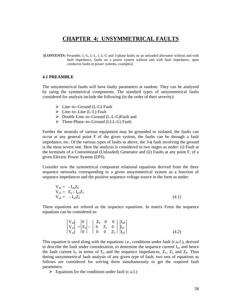
Equations for the sequence components (sequence equations) as per (4.2) above.4.2 SINGLE LINE TO GROUND FAULT ON A CONVENTIONAL (UNLOADED)
GENERATOR
Figure 4.1 LG Fault on a Conventional Generator
A conventional generator is one that produces only the balanced voltages. Let Ea, nd Ecbe the internally generated voltages and Zn be the neutral impedance. The fault isassumed to be on the phase’a’ as shown in figure 4.1. Consider now the conditions underfault as under:
c.u.f.:
Ib = 0; Ic = 0; and Va = 0. (4.3)
Now consider the symmetrical components of the current Ia with Ib=Ic=0, given by:
Ia0 1 1 1 Ia
Ia1 = (1/3) 1 a a2 0Ia2 1 a2 a 0 (4.4)
Solving (4.4) we get,
Ia1 = Ia2 = Ia0 = (Ia/3) (4.5)
Further, using equation (4.5) in (4.2), we get,
Va0 0 Z0 0 0 Ia1
Va1 = Ea – 0 Z1 0 Ia1
60
Va2 0 0 0 Z2 Ia1 (4.6)
Pre-multiplying equation (4.6) throughout by [1 1 1], we get,
Va1+Va2+Va0 = - Ia1Z0 + Ea – Ia1Z1 – Ia2Z2
i.e., Va = Ea – Ia1 (Z1 + Z2 + Z0) = zero,
Or in other words,
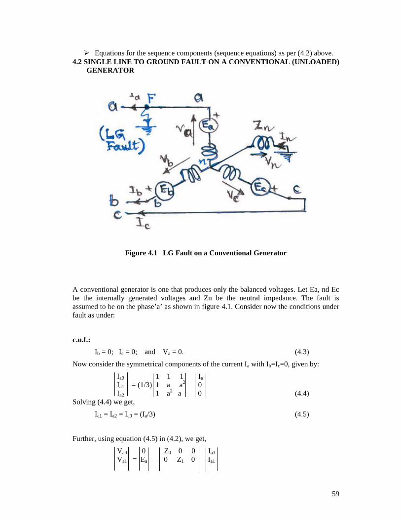
Ia1 = [Ea/(Z1 + Z2 + Z0)] (4.7)
.Figure 4.2 Connection of sequence networks for LG Fault
on phase a of a Conventional Generator
The equation (4.7) derived as above implies that the three sequence networks areconnected in series to simulate a LG fault, as shown in figure 4.2. Further we have thefollowing relations satisfied under the fault conditions:
1. Ia1 = Ia2 = Ia0 = (Ia/3) = [Ea/(Z1 + Z2 + Z0)]2. Fault current If = Ia = 3Ia1 = [3Ea/(Z1 + Z2 + Z0)]3. Va1 = Ea - Ia1Z1 = Ea(Z2+Z0)/(Z1+Z2+Z0)4. Va2 = - EaZ2/(Z1+Z2+Z0)5. Va0 = - EaZ0/(Z1+Z2+Z0)6. Fault phase voltage Va = 0,7. Sound phase voltages Vb = a2Va1+aVa2+Va0; Vc = aVa1+a2Va2+Va0
8. Fault phase power: VaIa* = 0, Sound pahse powers: VbIb
* = 0, and VcIc* = 0,
9. If Zn = 0, then Z0 = Zg0,
61
10. If Zn = , then Z0 = , i.e., the zero sequence network is open so that then,If=Ia=0.
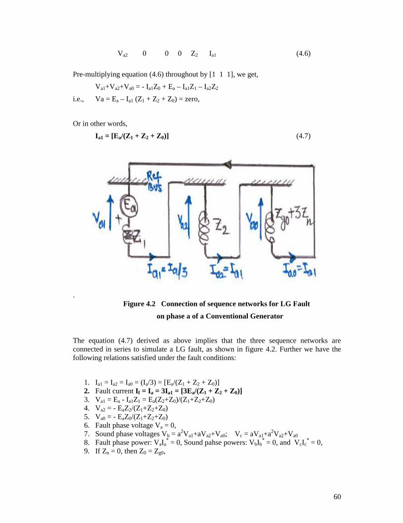
4.3 LINE TO LINE FAULT ON A CONVENTIONAL GENERATOR
Figure 4.3 LL Fault on a Conventional Generator
Consider a line to line fault between phase ‘b’ and phase ‘c’ as shown in figure 4.3, at theterminals of a conventional generator, whose neutral is grounded through a reactance.Consider now the conditions under fault as under:
c.u.f.:
Ia = 0; Ib = - Ic; and Vb = Vc (4.8)
Now consider the symmetrical components of the voltage Va with Vb=Vc, given by:
Va0 1 1 1 Va
Va1 = (1/3) 1 a a2 Vb
Va2 1 a2 a Vb (4.9)
Solving (4.4) we get,
Va1 = Va2 (4.10)
Further, consider the symmetrical components of current Ia with Ib=-Ic, and Ia=0; givenby:
Ia0 1 1 1 0Ia1 = (1/3) 1 a a2 Ib
Ia2 1 a2 a -Ib (4.11)
62
Solving (4.11) we get,
Ia0 = 0; and Ia2 = -Ia1 (4.12)
Using equation (4.10) and (4.12) in (4.2), and since Va0 = 0 ( Ia0 being 0), we get,
0 0 Z0 0 0 0Va1 = Ea – 0 Z1 0 Ia1
Va1 0 0 0 Z2 -Ia1 (4.13)Pre-multiplying equation (4.13) throughout by [0 1 -1], we get,
Va1-Va1 = Ea – Ia1Z1 – Ia1Z2 = 0
Or in other words,
Ia1 = [Ea/(Z1 + Z2)] (4.14)
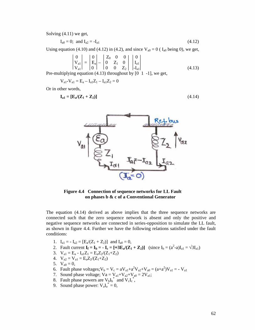
Figure 4.4 Connection of sequence networks for LL Faulton phases b & c of a Conventional Generator
The equation (4.14) derived as above implies that the three sequence networks areconnected such that the zero sequence network is absent and only the positive andnegative sequence networks are connected in series-opposition to simulate the LL fault,as shown in figure 4.4. Further we have the following relations satisfied under the faultconditions:
1. Ia1 = - Ia2 = [Ea/(Z1 + Z2)] and Ia0 = 0,2. Fault current If = Ib = - Ic = [3Ea/(Z1 + Z2)] (since Ib = (a2-a)Ia1 = 3Ia1)3. Va1 = Ea - Ia1Z1 = EaZ2/(Z1+Z2)4. Va2 = Va1 = EaZ2/(Z1+Z2)5. Va0 = 0,6. Fault phase voltages;Vb = Vc = aVa1+a2Va2+Va0 = (a+a2)Va1 = - Va1
7. Sound phase voltage; Va = Va1+Va2+Va0 = 2Va1;8. Fault phase powers are VbIb
* and VcIc*,
9. Sound phase power: VaIa* = 0,
63
10. Since Ia0=0, the presence of absence of neutral impedance does not make anydifference in the analysis.
4.4 DOUBLE LINE TO GROUND FAULT ON A CONVENTIONALGENERATOR
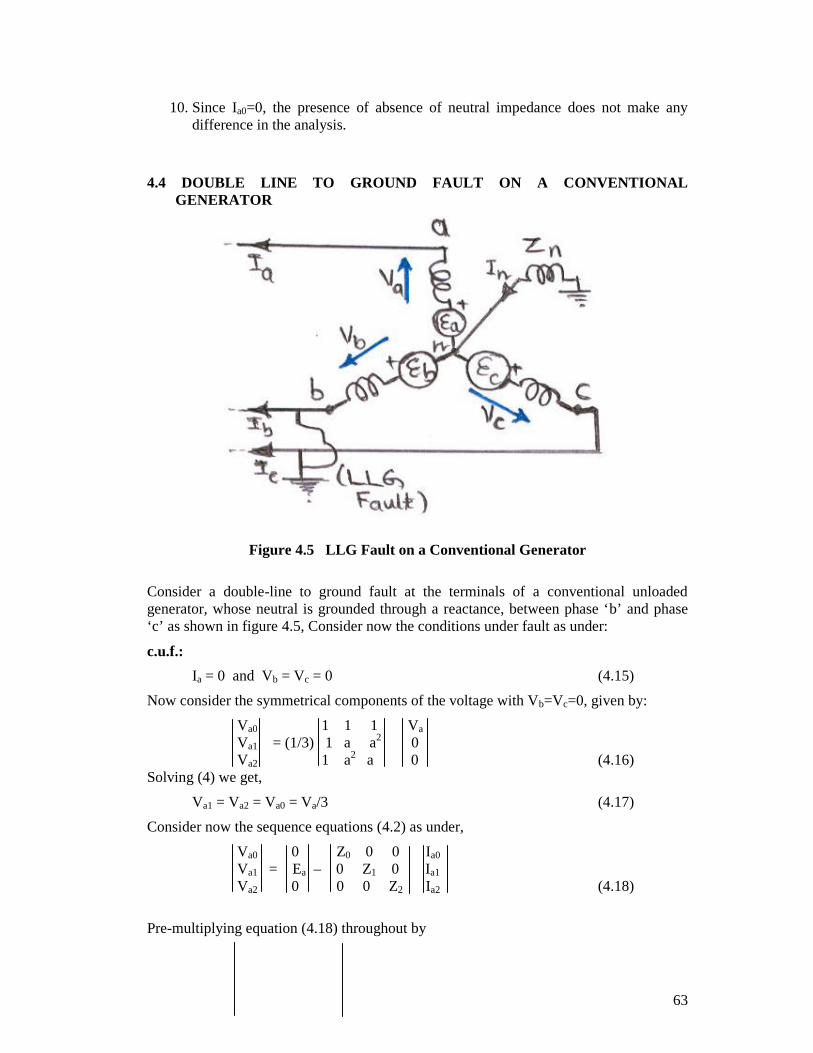
Figure 4.5 LLG Fault on a Conventional Generator
Consider a double-line to ground fault at the terminals of a conventional unloadedgenerator, whose neutral is grounded through a reactance, between phase ‘b’ and phase‘c’ as shown in figure 4.5, Consider now the conditions under fault as under:
c.u.f.:
Ia = 0 and Vb = Vc = 0 (4.15)
Now consider the symmetrical components of the voltage with Vb=Vc=0, given by:
Va0 1 1 1 Va
Va1 = (1/3) 1 a a2 0Va2 1 a2 a 0 (4.16)
Solving (4) we get,
Va1 = Va2 = Va0 = Va/3 (4.17)
Consider now the sequence equations (4.2) as under,
Va0 0 Z0 0 0 Ia0
Va1 = Ea – 0 Z1 0 Ia1
Va2 0 0 0 Z2 Ia2 (4.18)
Pre-multiplying equation (4.18) throughout by
64
1/Z0 0 0
Z-1 = 0 1/Z1 0
0 0 1/Z2 (4.19)
We get,
Va1 0 Z0 0 0 Ia0
Z-1 Va1 = Z-1 Ea – Z-1 0 Z1 0 Ia1
Va1 0 0 0 Z2 Ia2 (4.20)
Using the identity: Va1= (Ea – Ia1Z1) in equation (4.19), pre-multiplying throughout by [11 1] and finally adding, we get,
Ea/Z0 - Ia1(Z1/Z0) + (Ea/Z1)- Ia1 + Ea/Z2 - Ia1(Z1/Z2) = (Ea/Z1) – (Ia0+Ia1+Ia2)
= (Ea/Z1) - Ia = (Ea/Z1) (4.21)
Since Ia = 0, solving the equation (4.21), we get,
Ia1 = { Ea/ [Z1 + Z2Z0/(Z2+Z0)] } (4.22)
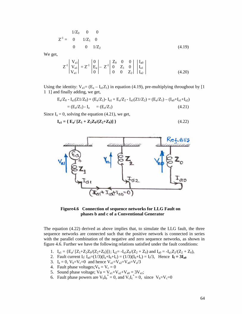
Figure4.6 Connection of sequence networks for LLG Fault onphases b and c of a Conventional Generator
The equation (4.22) derived as above implies that, to simulate the LLG fault, the threesequence networks are connected such that the positive network is connected in serieswith the parallel combination of the negative and zero sequence networks, as shown infigure 4.6. Further we have the following relations satisfied under the fault conditions:
1. Ia1 = {Ea/ [Z1+Z2Z0/(Z2+Z0)]}; Ia2= -Ia1Z0/(Z2 + Z0) and Ia0 = -Ia1Z2/(Z2 + Z0),2. Fault current If: Ia0=(1/3)(Ia+Ib+Ic) = (1/3)(Ib+Ic) = If/3, Hence If = 3Ia0
3. Ia = 0, Vb=Vc=0 and hence Va1=Va2=Va0=Va/34. Fault phase voltages;Vb = Vc = 05. Sound phase voltage; Va = Va1+Va2+Va0 = 3Va1;6. Fault phase powers are VbIb
* = 0, and VcIc* = 0, since Vb=Vc=0
65
7. Healthy phase power: VaIa* = 0, since Ia=0
8. If Z0=, (i.e., the ground is isolated), then Ia0=0, and hence the result is the sameas that of the LL fault [with Z0=, equation (4.22) yields equation (4.14)].
4.5 THREE PHASE TO GROUND FAULT ON A CONVENTIONALGENERATOR
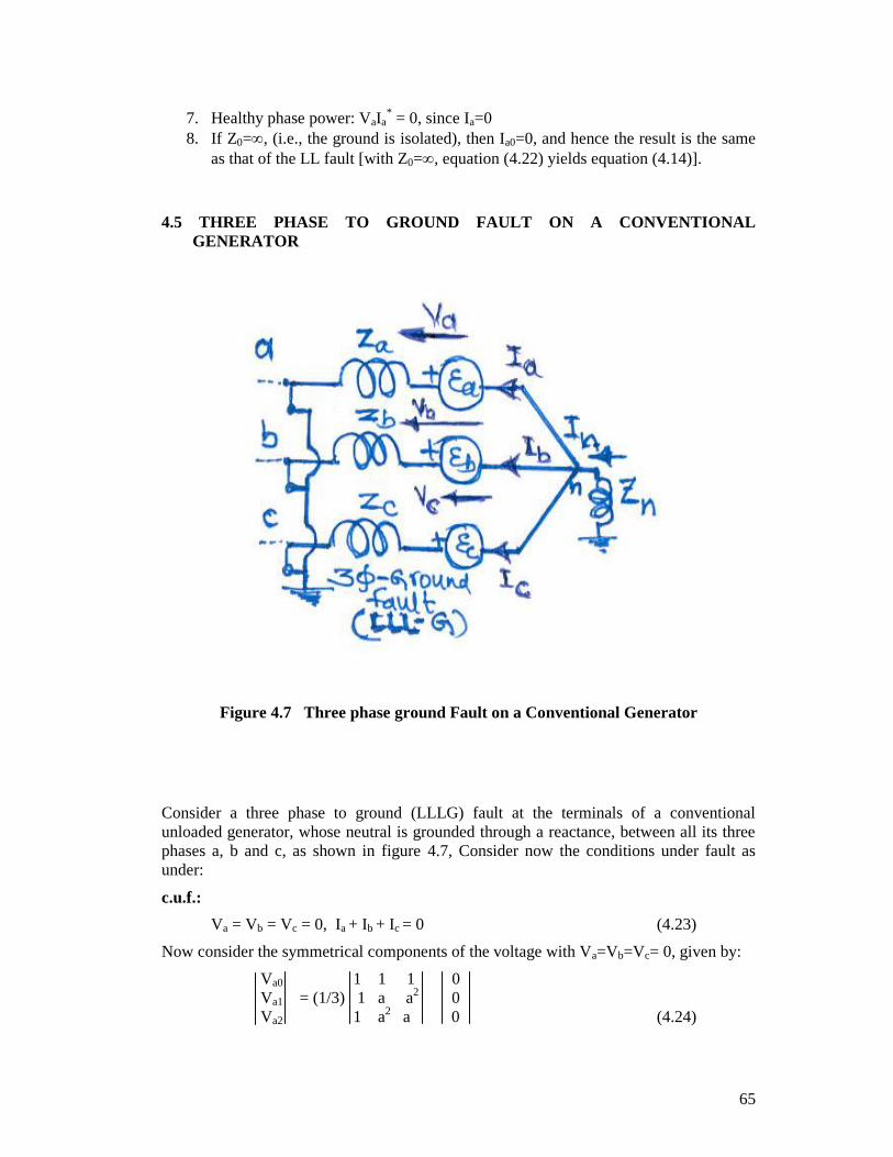
Figure 4.7 Three phase ground Fault on a Conventional Generator
Consider a three phase to ground (LLLG) fault at the terminals of a conventionalunloaded generator, whose neutral is grounded through a reactance, between all its threephases a, b and c, as shown in figure 4.7, Consider now the conditions under fault asunder:
c.u.f.:
Va = Vb = Vc = 0, Ia + Ib + Ic = 0 (4.23)
Now consider the symmetrical components of the voltage with Va=Vb=Vc= 0, given by:
Va0 1 1 1 0Va1 = (1/3) 1 a a2 0Va2 1 a2 a 0 (4.24)
66
Solving (4.24) we get,
Va1 = Va2 = Va0 = 0 (4.25)
Thus we have
Va1 = Ea1 – Ia1Z1 (4.26)
So that after solving for Ia1 we, get,
Ia1 = [ Ea / Z1 ] (4.27)
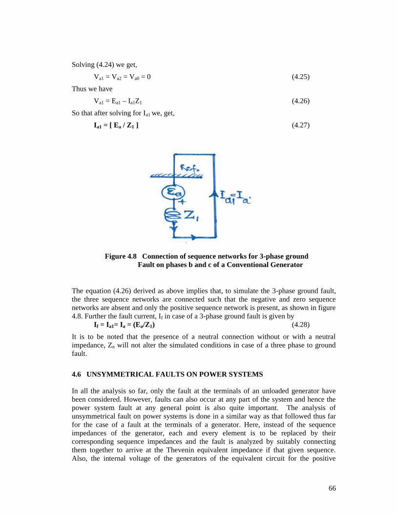
Figure 4.8 Connection of sequence networks for 3-phase groundFault on phases b and c of a Conventional Generator
The equation (4.26) derived as above implies that, to simulate the 3-phase ground fault,the three sequence networks are connected such that the negative and zero sequencenetworks are absent and only the positive sequence network is present, as shown in figure4.8. Further the fault current, If in case of a 3-phase ground fault is given by
If = Ia1= Ia = (Ea/Z1) (4.28)
It is to be noted that the presence of a neutral connection without or with a neutralimpedance, Zn will not alter the simulated conditions in case of a three phase to groundfault.
4.6 UNSYMMETRICAL FAULTS ON POWER SYSTEMS
In all the analysis so far, only the fault at the terminals of an unloaded generator havebeen considered. However, faults can also occur at any part of the system and hence thepower system fault at any general point is also quite important. The analysis ofunsymmetrical fault on power systems is done in a similar way as that followed thus farfor the case of a fault at the terminals of a generator. Here, instead of the sequenceimpedances of the generator, each and every element is to be replaced by theircorresponding sequence impedances and the fault is analyzed by suitably connectingthem together to arrive at the Thevenin equivalent impedance if that given sequence.Also, the internal voltage of the generators of the equivalent circuit for the positive
67
sequence network is now Vf (and not Ea), the pre-fault voltage to neutral at the point offault (PoF) (ref. Figure 4.9).
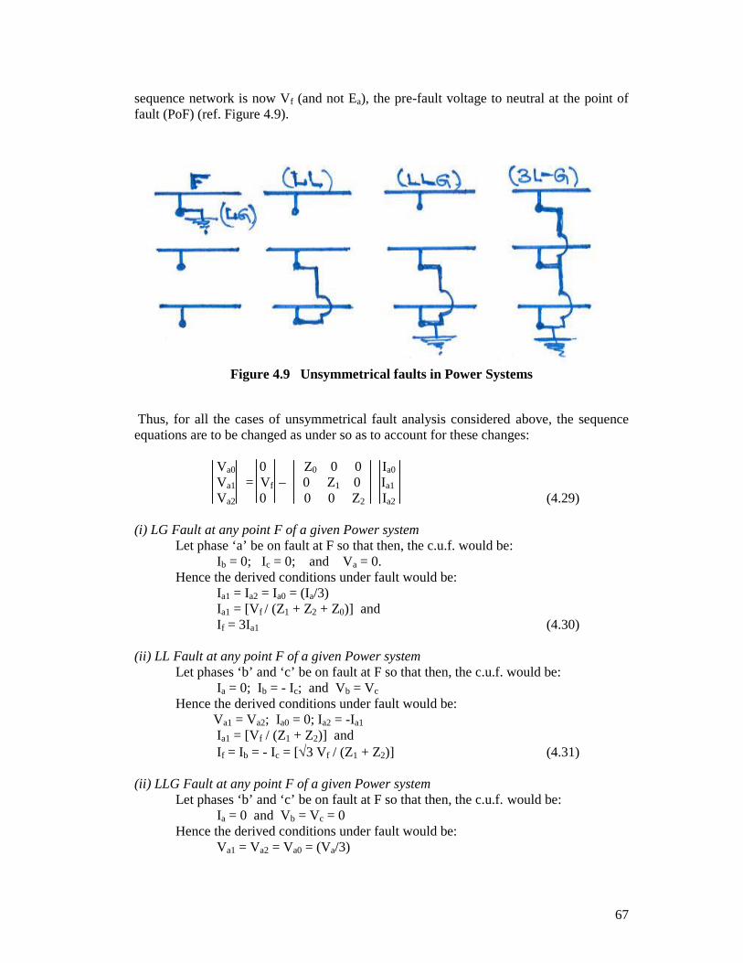
Figure 4.9 Unsymmetrical faults in Power Systems
Thus, for all the cases of unsymmetrical fault analysis considered above, the sequenceequations are to be changed as under so as to account for these changes:
Va0 0 Z0 0 0 Ia0
Va1 = Vf – 0 Z1 0 Ia1
Va2 0 0 0 Z2 Ia2 (4.29)
(i) LG Fault at any point F of a given Power systemLet phase ‘a’ be on fault at F so that then, the c.u.f. would be:
Ib = 0; Ic = 0; and Va = 0.Hence the derived conditions under fault would be:
Ia1 = Ia2 = Ia0 = (Ia/3)Ia1 = [Vf / (Z1 + Z2 + Z0)] andIf = 3Ia1 (4.30)
(ii) LL Fault at any point F of a given Power systemLet phases ‘b’ and ‘c’ be on fault at F so that then, the c.u.f. would be:
Ia = 0; Ib = - Ic; and Vb = Vc
Hence the derived conditions under fault would be:Va1 = Va2; Ia0 = 0; Ia2 = -Ia1
Ia1 = [Vf / (Z1 + Z2)] andIf = Ib = - Ic = [3 Vf / (Z1 + Z2)] (4.31)
(ii) LLG Fault at any point F of a given Power systemLet phases ‘b’ and ‘c’ be on fault at F so that then, the c.u.f. would be:
Ia = 0 and Vb = Vc = 0Hence the derived conditions under fault would be:
Va1 = Va2 = Va0 = (Va/3)
68
Ia1 = {Vf / [Z1+Z2Z0/(Z2+Z0)]}
Ia2= -Ia1Z0/(Z2 + Z2); Ia0 = -Ia1Z2/(Z2 + Z2) andIf = 3Ia0 (4.32)
(ii) Three Phase Fault at any point F of a given Power systemLet all the 3 phases a, b and c be on fault at F so that then, the c.u.f. would be:
Va = Vb = Vc = 0, Ia + Ib + Ic = 0Hence the derived conditions under fault would be:
Va1 = Va2 = Va0 = Va/3
Va0 = Va1 = Va2 = 0; Ia0 = Ia2 = 0,
Ia1 = [Vf /Z1] and If = Ia1=Ia (4.33)
4.7 OPEN CONDUCTOR FAULTS
Various types of power system faults occur in power systems such as the shunt type faults(LG, LL, LLG, LLLG faults) and series type faults (open conductor and cross countryfaults). While the symmetrical fault analysis is useful in determination of the rupturingcapacity of a given protective circuit breaker, the unsymmetrical fault analysis is useful inthe determination of relay setting, single phase switching and system stability studies.
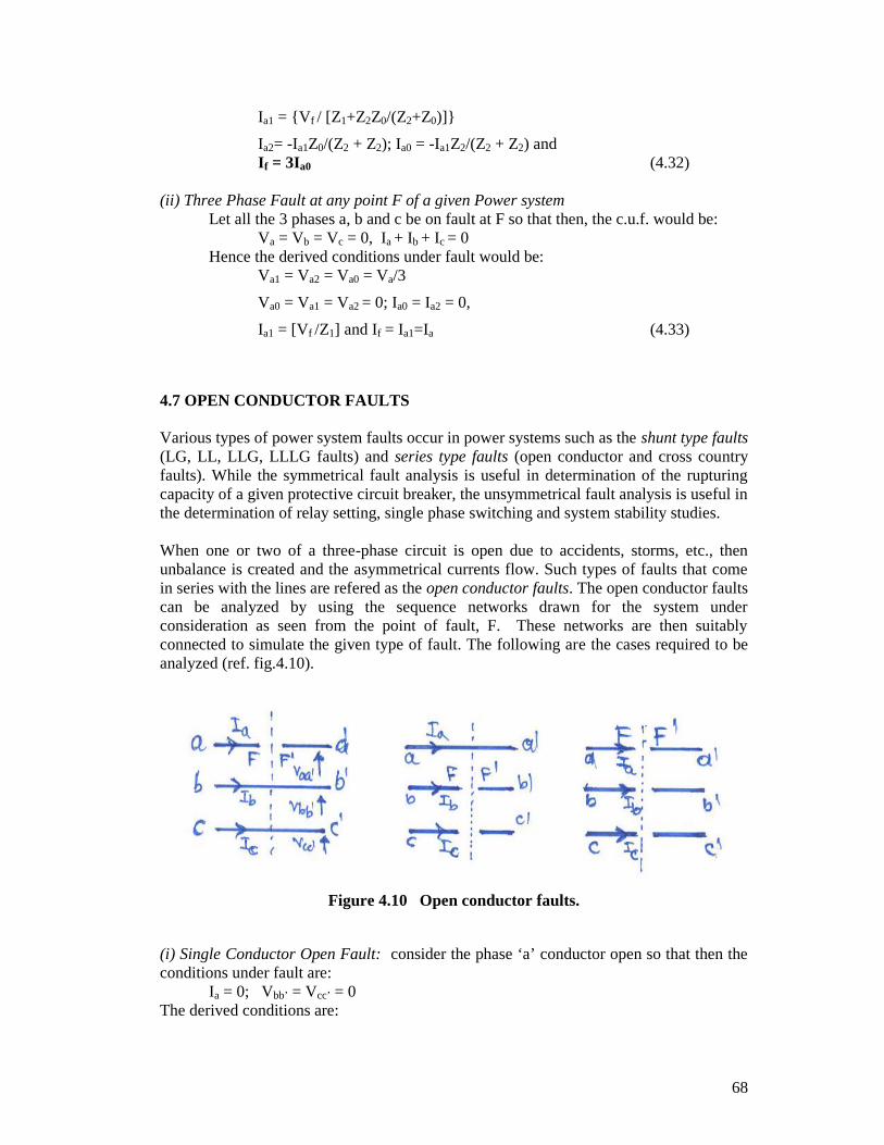
When one or two of a three-phase circuit is open due to accidents, storms, etc., thenunbalance is created and the asymmetrical currents flow. Such types of faults that comein series with the lines are refered as the open conductor faults. The open conductor faultscan be analyzed by using the sequence networks drawn for the system underconsideration as seen from the point of fault, F. These networks are then suitablyconnected to simulate the given type of fault. The following are the cases required to beanalyzed (ref. fig.4.10).
Figure 4.10 Open conductor faults.
(i) Single Conductor Open Fault: consider the phase ‘a’ conductor open so that then theconditions under fault are:
Ia = 0; Vbb’ = Vcc’ = 0The derived conditions are:
69
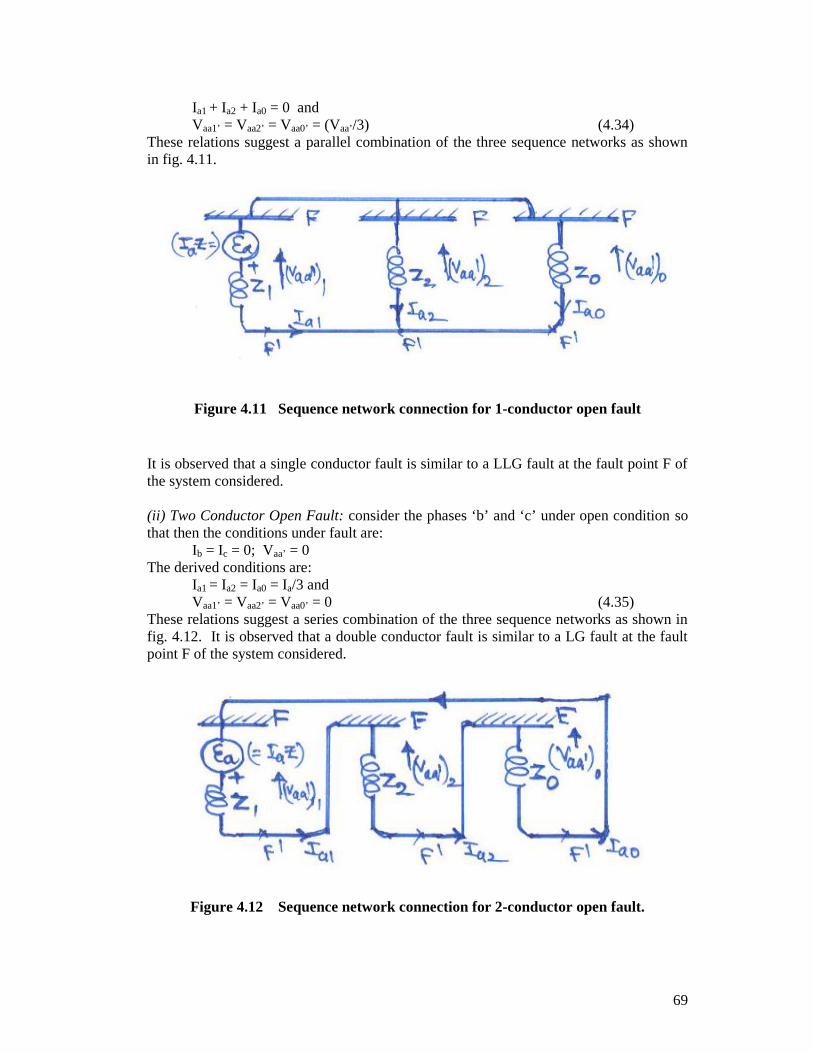
Ia1 + Ia2 + Ia0 = 0 andVaa1’ = Vaa2’ = Vaa0’ = (Vaa’/3) (4.34)
These relations suggest a parallel combination of the three sequence networks as shownin fig. 4.11.
Figure 4.11 Sequence network connection for 1-conductor open fault
It is observed that a single conductor fault is similar to a LLG fault at the fault point F ofthe system considered.
(ii) Two Conductor Open Fault: consider the phases ‘b’ and ‘c’ under open condition sothat then the conditions under fault are:
Ib = Ic = 0; Vaa’ = 0The derived conditions are:
Ia1 = Ia2 = Ia0 = Ia/3 andVaa1’ = Vaa2’ = Vaa0’ = 0 (4.35)
These relations suggest a series combination of the three sequence networks as shown infig. 4.12. It is observed that a double conductor fault is similar to a LG fault at the faultpoint F of the system considered.
Figure 4.12 Sequence network connection for 2-conductor open fault.
70
(iii) Three Conductor Open Fault: consider all the three phases a, b and c, of a 3-phasesystem conductors be open. The conditions under fault are:
Ia + Ib + Ic = 0The derived conditions are:
Ia1 = Ia2 = Ia0 = 0 andVa0 = Va2 = 0 and Va1 = Vf (4.36)
These relations imply that the sequence networks are all open circuited. Hence, in a strictanalystical sense, this is not a fault at all!
4.8 FAULTS THROUGH IMPEDANCE
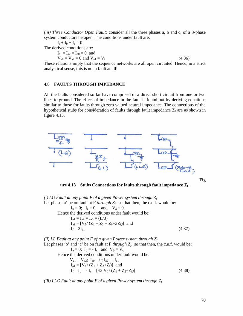
All the faults considered so far have comprised of a direct short circuit from one or twolines to ground. The effect of impedance in the fault is found out by deriving equationssimilar to those for faults through zero valued neutral impedance. The connections of thehypothetical stubs for consideration of faults through fault impedance Zf are as shown infigure 4.13.
Figure 4.13 Stubs Connections for faults through fault impedance Zf.
(i) LG Fault at any point F of a given Power system through Zf
Let phase ‘a’ be on fault at F through Zf, so that then, the c.u.f. would be:Ib = 0; Ic = 0; and Va = 0.
Hence the derived conditions under fault would be:Ia1 = Ia2 = Ia0 = (Ia/3)Ia1 = [Vf / (Z1 + Z2 + Z0+3Zf)] andIf = 3Ia1 (4.37)
(ii) LL Fault at any point F of a given Power system through Zf
Let phases ‘b’ and ‘c’ be on fault at F through Zf, so that then, the c.u.f. would be:Ia = 0; Ib = - Ic; and Vb = Vc
Hence the derived conditions under fault would be:Va1 = Va2; Ia0 = 0; Ia2 = -Ia1
Ia1 = [Vf / (Z1 + Z2+Zf)] andIf = Ib = - Ic = [3 Vf / (Z1 + Z2+Zf)] (4.38)
(iii) LLG Fault at any point F of a given Power system through Zf
71
Let phases ‘b’ and ‘c’ be on fault at F through Zf,, so that then, the c.u.f. would be:Ia = 0 and Vb = Vc = 0
Hence the derived conditions under fault would be:Va1 = Va2 = Va0 = (Va/3)
Ia1 = {Vf / [Z1+Z2(Z0+3Zf)/(Z2+Z0+3Zf)]}
Ia2= -Ia1(Z0+3Zf)/(Z2+Z0+3Zf); Ia0 = -Ia1Z2/(Z2+(Z0+3Zf) andIf = 3Ia0 (4.39)
(iv) Three Phase Fault at any point F of a given Power system through Zf
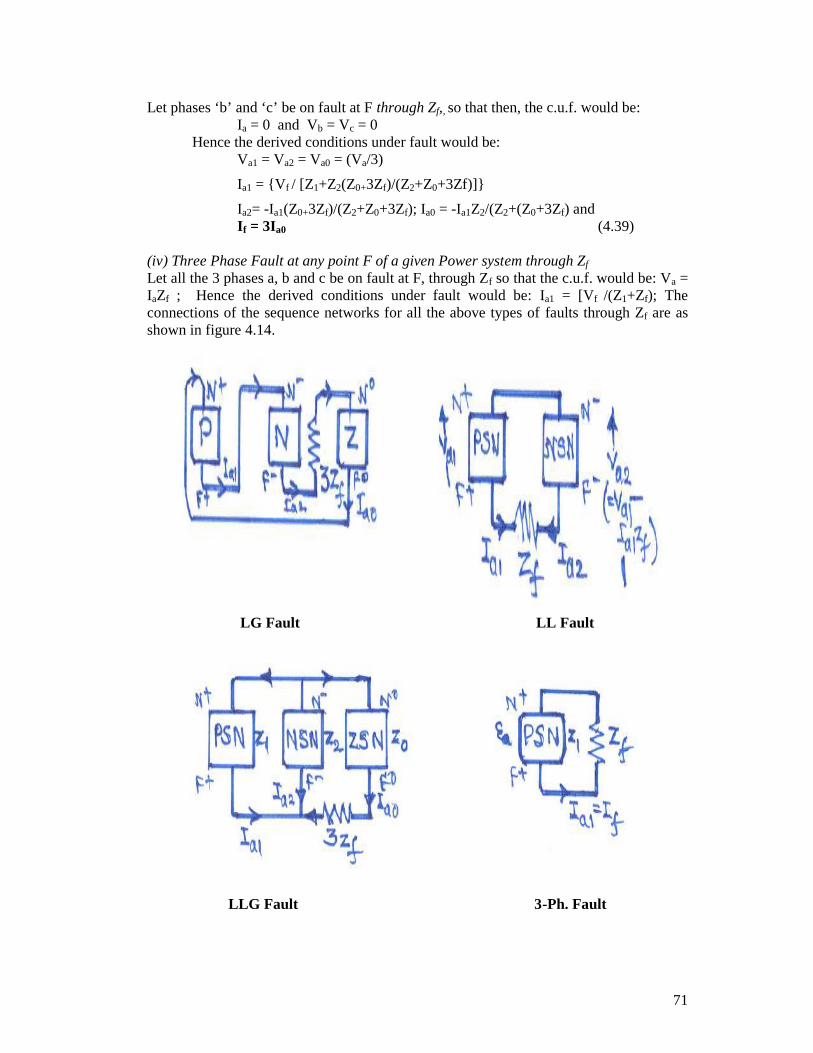
Let all the 3 phases a, b and c be on fault at F, through Zf so that the c.u.f. would be: Va =IaZf ; Hence the derived conditions under fault would be: Ia1 = [Vf /(Z1+Zf); Theconnections of the sequence networks for all the above types of faults through Zf are asshown in figure 4.14.
LG Fault LL Fault
LLG Fault 3-Ph. Fault
72
Figure 4.15 Sequence network connections for faults through impedance
4.9 EXAMPLES
Example-1: A three phase generator with constant terminal voltages gives the followingcurrents when under fault: 1400 A for a line-to-line fault and 2200 A for a line-to-groundfault. If the positive sequence generated voltage to neutral is 2 ohms, find the reactancesof the negative and zero sequence currents.
Solution: Case a) Consider the conditions w.r.t. the LL fault:
Ia1 = [Ea1/(Z1 + Z2)]
If = Ib = - Ic = 3 Ia1
=3 Ea1 / (Z1 + Z2) or
(Z1 + Z2) = 3 Ea1 / If
i.e., 2 + Z2 = 3 [2000/1400]
Solving, we get, Z2 = 0.474 ohms.
Case b) Consider the conditions w.r.t. a LG fault:
Ia1 = [Ea1/(Z1 + Z2+Z0)]
If = 3 Ia1
= 3 Ea1 / (Z1 + Z2+Z0) or
(Z1 + Z2+Z0) = 3 Ea1 / If
i.e., 2 + 0.474 + Z0 = 3 [2000/2200]
Solving, we get, Z0 = 0.253 ohms.
Example-2: A dead fault occurs on one conductor of a 3-conductor cable supplied y a 10MVA alternator with earhed neutral. The alternator has +ve, -ve and 0-sequencecomponents of impedances per phase respectively as: (0.5+j4.7), (0.2+j0.6) and (j0.43)ohms. The corresponding LN values for the cable up to the point of fault are:(0.36+j0.25), (0.36+j0.25) and (2.9+j0.95) ohms respectively. If the generator voltage atno load (Ea1) is 6600 volts between the lines, determine the (i)Fault current, (ii)Sequencecomponents of currents in lines and (iii)Voltages of healthy phases.
Solution: There is LG fault on any one of the conductors. Consider the LG fault to be onconductor in phase a. Thus the fault current is given by:
(i) Fault current: If = 3Ia0 = [3Ea/(Z1 + Z2 + Z0)]
= 3(6600/3)/ (4.32+j7.18)
= 1364.24 58.970.
73
(ii) Sequence components of line currents:
Ia1 = Ia2 = Ia0 = Ia/3 = If/3 = 454.75 58.970.
(iii) Sound phase voltages:Va1 = Ea - Ia1Z1 = Ea(Z2+Z0)/(Z1+Z2+Z0) = 1871.83 -26.170,Va2 = - EaZ2/(Z1+Z2+Z0) = 462.91 177.60,Va0 = - EaZ0/(Z1+Z2+Z0) = 1460.54 146.50,
Thus,Sound phase voltages Vb = a2Va1+aVa2+Va0 = 2638.73 -165.80 Volts,And Vc = aVa1+a2Va2+Va0 = 3236.35 110.80 Volts.
Example-3: A generator rated 11 kV, 20 MVA has reactances of X1=15%, X2=10% andX0=20%. Find the reactances in ohms that are required to limit the fault current to 2 p.u.when a a line to ground fault occurs. Repeat the analysis for a LLG fault also for a faultcurrent of 2 pu.
Solution: Case a: Consider the fault current expression for LG fault given by:
If = 3 Ia0
i.e., 2.0 = 3Ea / j[X1+X2+X0]
= 3(1.000) / j[0.15+0.1+0.2+3Xn]
Solving we get
3Xn = 2.1 pu
= 2.1 (Zb) ohms = 2.1 (112/20) = 2.1(6.05)
= 12.715 ohms.
Thus Xn = 4.235 ohms.
Case b: Consider the fault current expression for LLG fault given by:If = 3Ia0 = 3 { -Ia1X2/(X2 + X0+3Xn)}= 2.0,
where, Ia1 = {Ea/ [X1+X2(X0+3Xn)/(X2+X0+3Xn)]}Substituting and solving for Xn we get,
Xn = 0.078 pu= 0.47 ohms.
Example-4: A three phase 50 MVA, 11 kV generator is subjected to the various faultsand the surrents so obtained in each fault are: 2000 A for a three phase fault; 1800 A for aline-to-line fault and 2200 A for a line-to-ground fault. Find the sequence impedances ofthe generator.
Solution: Case a) Consider the conditions w.r.t. the three phase fault:
If = Ia = Ia1 = Ea1/Z1
i.e., 2000 = 11000/ (3Z1)
Solving, we get, Z1 = 3.18 ohms (1.3 pu, with Zb = (112/50) = 2.42 ohms).
74
Case b) Consider the conditions w.r.t. the LL fault:
Ia1 = [Ea1/(Z1 + Z2)]
If = Ib = - Ic = 3 Ia1
=3 Ea1 / (Z1 + Z2) or
(Z1 + Z2) = 3 Ea1 / If
i.e., 3.18 + Z2 = 3 (11000/3)/1800
Solving, we get, Z2 = 2.936 ohms = 1.213 pu.
Case c) Consider the conditions w.r.t. a LG fault:
Ia1 = [Ea1/(Z1 + Z2+Z0)]
If = 3 Ia1
= 3 Ea1 / (Z1 + Z2+Z0) or
(Z1 + Z2+Z0) = 3 Ea1 / If
i.e., 3.18+ 2.936 + Z0 = 3 (11000/3)/ 2200
Solving, we get, Z0 = 2.55 ohms = 1.054 pu.