earthquake nucleation on (aging) rate and state faults - core
TRANSCRIPT
Earthquake nucleation on (aging) rate and state
faults
A. M. Rubin and J.-P. Ampuero1
Department of Geosciences, Princeton University, Princeton, New Jersey, USA
Received 11 February 2005; revised 3 August 2005; accepted 31 August 2005; published 29 November 2005.
[1] We obtain quasi-static, two-dimensional solutions for earthquake nucleation on faultsobeying Dieterich’s ‘‘aging’’ version of the rate and state friction equations. Two distinctnucleation regimes are found, separated by roughly a/b � 0.5, where a and b are theconstitutive parameters relating changes in slip rate V and state q to frictional strength.When fault healing is unimportant (Vq/Dc � 1, where Dc is the characteristic slip distancefor the evolution of q), the nucleation zone spontaneously evolves toward a state ofaccelerating slip on a patch of fixed half length Ln � 1.3774(m0Dc/bs), where m0 is theintrinsic stiffness of the medium and s is the normal stress. This is the fixed lengthsolution for which the stress intensity factor K = 0. Although this solution does not dependupon a/b explicitly, only for a/b < 0.3781 does healing remain unimportant as instability isapproached. For a/b ^ 0.5 and a wide range of slow loading conditions, Vq/Dc
ultimately approaches a quasi-constant value near 1, and the nucleation zone takes on theappearance of an expanding slip-weakening crack. A fracture energy balance indicates thatin this regime the nucleation length asymptotically approaches p�1[b/(b � a)]2(m0Dc/bs), aresult that is consistent with the numerical simulations despite considerable complexityas a approaches b. This suggests that nucleation lengths can sometimes be muchlarger than those found by Dieterich (e.g., by a factor of 100 for a/b = 0.95). For surfacesthis close to velocity neutral, nucleation might produce signals detectable by surfaceseismometers for values of Dc at the upper end of the lab range (100 mm). However, theattributes of the aging law that give rise to such large nucleation lengths may benonphysical; additional laboratory experiments are needed to address this issue.
Citation: Rubin, A. M., and J.-P. Ampuero (2005), Earthquake nucleation on (aging) rate and state faults, J. Geophys. Res., 110,
B11312, doi:10.1029/2005JB003686.
1. Introduction
[2] Laboratory studies by Dieterich and others haveshown that frictional strength depends upon the ‘‘state’’ ofthe sliding surface as well as the sliding velocity [Dieterich,1979; Tullis, 1988; Marone, 1998]. A standard form of theconstitutive law is
ts¼ f *þ a ln
V
V*þ b ln
V*qDc
; ð1Þ
where t is the frictional strength, s is the normal stress, V isthe sliding velocity, q is the state variable (with units oftime), Dc is a characteristic sliding distance for the evolutionof q (of order 10 mm for bare rock surfaces in the laboratorybut up to 100 mm for gouge), f* and V* are reference valuesof the friction and velocity, and a and b are both positiveand of order 10�2. The parameter a characterizes the
magnitude of the ‘‘direct effect’’, the increase in strengthwith increasing sliding velocity (at constant state), and bcharacterizes the magnitude of the ‘‘evolution effect’’,thought to reflect the increase in strength with increasingtotal area and/or cohesiveness of points of contact.[3] Assuming nonzero sliding velocities, equilibrium dic-
tates that the frictional strength equal the fault stress, whichwe partition into a boundary condition t1 and an elasticcomponent tel due to nonuniform fault slip. Because mostof the nucleation process takes place while inertial effectsare unimportant, we focus on the quasi-static limit here. Intwo dimensions the static elastic stresses are proportional tothe Hilbert transformH of the along-fault gradients in slip d:
t xð Þ ¼ t1 xð Þ þ tel xð Þ ¼ t1 xð Þ þ m0
2H d0½ xð Þ; ð2Þ
where
H d0½ xð Þ � 1
p
Z 1
�1
dd=dss� x
ds:
In (2), m0 represents the elastic shear modulus for antiplanedeformation and the shear modulus divided by one minusPoisson’s ratio for plane strain deformation, and d0 = dd/dx.
JOURNAL OF GEOPHYSICAL RESEARCH, VOL. 110, B11312, doi:10.1029/2005JB003686, 2005
1Now at Institute of Geophysics, Seismology and Geodynamics,ETH-Honggerberg, Zurich, Switzerland.
Copyright 2005 by the American Geophysical Union.0148-0227/05/2005JB003686$09.00
B11312 1 of 24
[4] In contrast to the direct effect a (ln [V/V*]), whichappears to have a plausible basis in terms of a thermallyactivated Arrhenius process [Rice et al., 2003], laws for theevolution of state are essentially empirical. In this study weadopt Dieterich’s ‘‘aging’’ law, which accounts for thelaboratory observation that a fault surface strengthens or‘‘heals’’ during stationary contact [Beeler et al., 1994;Dieterich and Kilgore, 1994; Marone, 1998]. With dotsdenoting time derivatives, this is written
_q ¼ 1� V qDc
: ð3Þ
The first term on the right embodies the healing and showsthat it accrues as elapsed time. The Vq/Dc term representsthe weakening rate due to slip, or, as the healing rate isunity, the ratio of the weakening to healing rates. Becausethis quantity plays such a prominent role in this paper, wedefine the notation
W � VqDc
: ð4Þ
When W = 1 the fault is at steady state (_q = 0). Following astep change in sliding velocity, q evolves to a new steadystate over the characteristic slip distance Dc.[5] In equation (1), f * and V* are defined such that t =
s f * when sliding at steady state with V = V*, so that atsteady state, (1) reduces to
t ¼ s f *þ a� b½ ln V
V*
� �: ð5Þ
For a < b the surface weakens with increasing slidingvelocity (at steady state) and is prone to instability; for a > bthe surface is steady state velocity strengthening and slidingis stable. For temperatures and pressures appropriate for theseismogenic crust rock tends to be close to velocity neutral,to the extent that different experimental configurationssometimes lead to opposing determinations of the sign of(a � b) even for loading conditions that are nominally thesame [Marone, 1998]. Even considering only those experi-ments which show velocity-weakening behavior, a goodmedian value of a/b for granite is 0.9 (both for bare surfacesunder a wide range of normal stress and slip speed [Kilgore etal., 1993], and for wet or nominally dry gouge under a widerange of temperature [Blanpied et al., 1998]).[6] Despite two decades of interest in equations (1) and
(3), their implications for the size of the nucleation zone onelastically deformable faults remains unclear. From a linearstability analysis, Ruina [1983] found the critical stiffness(the maximum permitting instability) of a spring-blockslider to be s(b � a)/Dc. Because stiffness in an elasticmedium is roughly inversely proportional to size, thiswould seem to imply a nucleation length (or at least aminimum possible earthquake size) that scales roughly asm0Dc/(b � a)s [Rice, 1993]. On the other hand, in anumerical study of earthquake nucleation in an elasticmedium, Dieterich [1992] found the nucleation length toscale as m0Dc/bs, a result that was later shown to beconsistent with laboratory experiments on meter-scale
blocks of rock [Dieterich and Kilgore, 1996]. Dieterichpointed out that as slip accelerates and nucleation is wellunderway, the sliding velocity may greatly exceed steadystate (V � Dc/q), in which case (3) reduces to
_q � �VqDc
¼ �W: ð6Þ
We refer to this approximation as the ‘‘no-healing’’ limit,and with it, Dieterich [1994] obtained analytical solutionssupporting his observation of scaling as b�1 rather than(b � a)�1, as well as his well-known results for earthquakeaftershock rates. However, since q decreases as V increasesduring the approach to instability (when W > 1), it is notimmediately evident from (3) when (6) becomes valid. Tocomplicate the matter further, Lapusta and Rice [2002]describe numerical results that are inconsistent with both theb�1 and (b � a)�1 scaling. As these length scales appearrepeatedly in this paper, we introduce the notation
Lb �m0Dc
bs; Lb�a �
m0Dc
b� að Þs : ð7Þ
Because large earthquakes and transient creep events oftenappear to nucleate near the base of the seismogenic zone,near the transition from velocity weakening to velocitystrengthening where Lb and Lb�a diverge, understandingwhat controls the nucleation length under these conditionswould seem to be important.[7] For completeness, we state here the second common
equation for the evolution of q, referred to as the ‘‘slip’’law because no evolution occurs during stationary contact:
_q ¼ �VqDc
lnV qDc
¼ �WlnW: ð8Þ
For small departures from steady state (W = 1 + �, withj�j � 1), (8) asymptotically approaches (3). In recent yearsthe slip law seems to have fallen out of favor somewhat,probably because the aging law has been shown to besuperior in the range W � 1 where healing dominates[Beeler et al., 1994]. In hindsight, however, it appears to bethe range W � 1 to W � 1 that controls the nucleation size.On the basis of the results to follow, we expect nucleation tobe sometimes significantly different under the two laws.Further experimental and theoretical work to sort this out iscertainly warranted.[8] This paper is organized as follows. In section 2 we
present numerical simulations that mimic those of Dieterich[1992], and illustrate two fundamentally different nucleationregimes distinguished by the behavior of W. In the firstregime W � 1 everywhere, and nucleation is characterizedby accelerating slip on a patch of fixed length. In the secondregime W in the interior of the nucleation zone tends to aquasi-constant (and a/b-dependent) value of order 1, acondition we refer to as the ‘‘constant-weakening’’ limit.Nucleation in this case takes the form of an expanding crackwith time-varying slip-weakening properties.[9] In section 3 we derive a separable solution for fixed
length nucleation in the limit W � 1. Requiring the stressesat the ends of the nucleation zone to remain finite fixes the
B11312 RUBIN AND AMPUERO: RATE AND STATE EARTHQUAKE NUCLEATION
2 of 24
B11312
nucleation (half)length to be 1.3774Lb, for practical pur-poses identical to the value identified by Dieterich [1992]on the basis of numerical simulations. Within this solution,however, only for a/b < 0.3781 does W increase during theapproach to instability. For larger a/b, W decreases and forour adopted loading conditions the Dieterich approximationbecomes invalid before elastodynamic speeds are reached.Relaxing the finite stress constraint, we find that for a/b <0.3781 instabilities can nucleate within regions smaller than1.3774Lb. Such solutions may be relevant for fault segmentsbounded by strong barriers, and provide direct evidence thatnucleation zones need not evolve to the shortest lengthpermitting instability. For a/b = 0 this shortest lengthcoincides with the value 0.579Lb found for linear slip-weakening friction by Uenishi and Rice [2003].[10] In section 4 we explore nucleation in the constant-
weakening regime. A fracture energy balance shows that inthe limit of large slip speeds the nucleation half lengthapproaches p�1[b/(b � a)]2Lb. This estimate is well sup-ported by the simulations, although how closely the nucle-ation length approaches this value by the time dynamic slipspeeds are reached depends upon the loading conditions.We close this section by examining some implications forthe detectability of seismic nucleation phases, and discussthe (perhaps suspect) aspects of the aging law that give riseto such large nucleation zones for a near b.[11] The fixed length solution essentially guarantees that
nucleation for low a/b occurs in the no-healing regime, but
whether nucleation for larger a/b occurs in the constant-weakening regime depends also upon the loading condi-tions. Both regimes represent mature phases of nucleation inwhich the region of accelerating slip is already highlylocalized. They are preceded by an earlier localization phasecharacterized by an increasing W. If the value of W uponlocalization is large enough, then over some velocity rangethe no-healing solution is followed even for large a/b. Insection 5 and related appendices we derive analytic resultsthat are useful for assessing qualitatively the evolution of Wduring these earliest stages of nucleation, and the related(and perhaps more general) question of what determineswhether the nucleation zone expands or contracts.
2. Quasi-Static Numerical Simulations
[12] To solve the governing equations numerically, weequate (1) and (2) and differentiate with respect to time toobtain
a_V
Vþ b
_qq¼ _t
s
1þ m0
2sH V 0½ : ð9Þ
The parameters s, a, and b are taken to be constant anduniform, while V, q, and perhaps _t1 vary in space and time.We compute the elastic stresses from the velocity gradientsin the spectral domain, using the result that for each wavenumber k the stressing rate is related to the velocity Vk by_tk = �Vkm
0jkj/2.
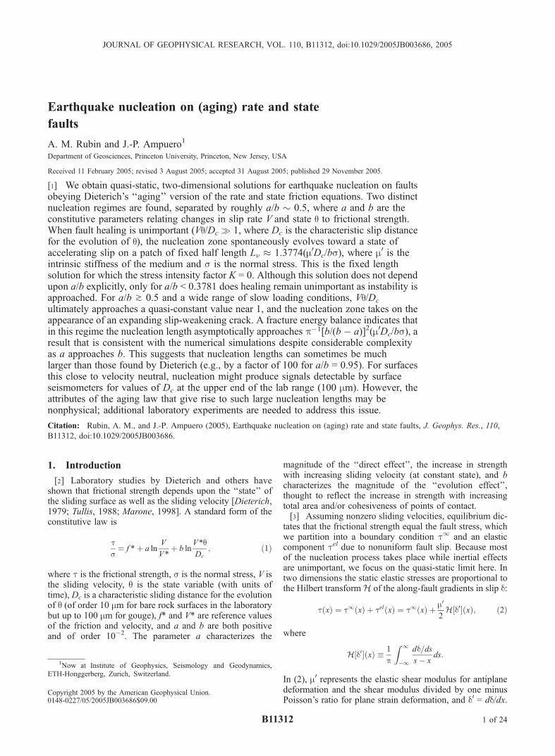
Figure 1. Snapshots of (a, c, e) velocity and (b, d, f) W � Vq/Dc for a fault with heterogeneous initialconditions and a/b = 0.3 (Figures 1a and 1b), 0.5 (Figures 1c and 1d), and 0.8 (Figures 1e and 1f). Thebold velocity profiles extend from stressing rate peak to stressing rate peak when that distance reaches itsminimum value (2Lmin). In this and all subsequent figures, m0 = 11.56 GPa, s = 100 MPa, Dc = 0.4 mm,and (unless noted otherwise) b = 0.01.
B11312 RUBIN AND AMPUERO: RATE AND STATE EARTHQUAKE NUCLEATION
3 of 24
B11312
[13] Together, equations (9) and (3) allow one to compute_v and _q in terms of the known q, V and _t1 at the start of eachtime step. The change in V and q during a time step ofduration Dt are then _VDt and _qDt. We solve these equationson a grid of 213–216 points along the fault, with a uniformspacing of 0.05–0.5 m, using the adaptive time steppingBulirsch-Stoer routine of Press et al. [1986].[14] We first show results of simulations where the fault is
initially healing (W < 1). Because the fault strengthens as thelogarithm of time, a remote stress that increases linearlywith time ensures that the fault ultimately progresses tofailure by passing through steady state (W = 1) from below.In these simulations the initial velocity is 10�9 m/s, theremote stressing rate is 10�2 Pa/s, and the initial state israndomly distributed between 0 and Dc/V (steady state). Thenucleation zone first passes through steady state at avelocity of �10�12–10�11 m/s. In Appendix A2 we exam-ine the limit cycle oscillations of a spring-block slider withradiation damping, and estimate the velocity at which a‘‘locked’’ fault crosses the steady state curve to be a feworders of magnitude less than the driving plate velocity.Thus we believe that, at least in a very gross sense, oursimulations generate an appropriate range of velocitiesbetween the initial crossing of the steady state curve andelastodynamic speeds.[15] Figure 1 shows the evolution of both V and W for b =
0.01 and three values of a/b, and illustrates the main stylesof nucleation we observe. In the upper panels, the velocityinitially decreases but increases between the second andthird snapshots. Larger values of a lead to more rapidsmoothing of the initial heterogeneity through the directvelocity effect (increased frictional resistance where thevelocity is largest). This is also consistent with the linearstability analysis of Rice and Riuna [1983], which showsthat variations on length scales shorter than Lb�a aredamped. For a/b = 0.3, the instability appears to grow inamplitude while maintaining a fixed shape. For a/b = 0.5,the instability appears initially to maintain that same shape,but eventually the velocity profile flattens in the center. Weshow in section 3 that this distinction from a/b = 0.3 is notan artifact of the number of time steps taken. For a/b = 0.8the nucleation zone first localizes and then expands in acrack-like fashion (peak velocities near the tips; relativelyuniform velocities in the interior). In the lower panels, Wfirst decreases and then increases between the second andthird snapshots. Near the center of the instability, Wincreases monotonicallly for a/b = 0.3, but eventuallydecreases to a quasi-constant and quasi-uniform value near1 for a/b = 0.5 and 0.8.[16] In their study of earthquake nucleation on a slip-
weakening fault, Uenishi and Rice [2003] found that in thepresence of a peaked and uniformly increasing load, theslipping region expands continuously until a stable elasticconfiguration no longer exists. This largest stable size is anobvious choice for the definition of nucleation length forslip-weakening friction. For rate-and-state friction this def-inition is inappropriate, both because the entire surface isslipping and because it appears that the nucleation zone firstshrinks via some localization process (this localization ismost easily seen in snapshots of the stressing rate, anexample of which is shown in Figure 4 in section 3). Byanalogy with crack expansion on an otherwise stationary
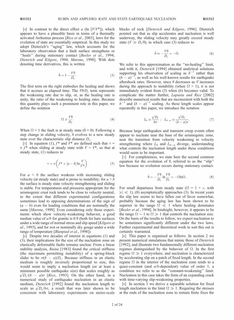
surface, we adopt as a quantitative measure of nucleationlength half the distance between the peaks in elastic stress-ing rate to either side of the nucleating patch. We defineLmin to be the first minimum of the time-dependent nucle-ation length following the localization process. The boldcurves in Figure 1 show the velocity profiles at thisminimum length, drawn from stressing rate peak to stressingrate peak, so their length is 2Lmin.[17] The values of Lmin for several dozen simulations are
summarized in Figure 2. For each set of loading conditions,simulations were carried out for 5 values of b (in equalincrements from 0.005 to 0.025) and 9 values of a/b. Thenucleation lengths are normalized by Lb. The dimensionlessversions of the governing equations (Appendix A1) showthat, with this scaling, varying b at a constant a/b isequivalent to varying either the initial values of both Vand q�1, or s/ _t1, by the same factor. The set of simulationsfrom which the panels of Figure 1 were extracted are shownby open circles. The squares are for the same conditionsexcept that the initial state was randomly distributed be-tween 0.495 and 0.505 times Dc/V, rather than between 0and Dc/V. The small solid circles are for a homogeneousfault undergoing steady state sliding (W = 1) that is thensubjected to a remote loading rate restricted to a regionthat is small compared to Lmin (0.1Lb�a). The triangles arefor a fault on which W peaks at 1 at the origin anddecreases smoothly to 10�1/2 at a distance of 2Lb�a toeither side, subjected to a uniform remote stressing rate of10�3 Pa/s.
Figure 2. Plot of normalized Lmin, defined as half theminimum (time-dependent) distance between stressing ratepeaks at opposite ends of the nucleation zone, for four suitesof simulations with differing boundary/initial conditions andvariable b and a/b. The normalizing length scale Lb � m0Dc/bs. For a/b = 0.9 and a few values of b the algorithm fordetecting the minimum length was unsuccessful; thoseresults are not shown. The horizontal dashed line shows thelength equal to 95.83% of that given by equation (21). Thedotted curve below that shows the estimate from equation(26) of the shortest nucleation zone capable of reachinginstability via the no-healing, fixed length solution ofsection 3. The dashed curve shows scaling of the nucleationlength as (b � a)�1, arbitrarily scaled to the simulationresults for a = 0, and is drawn only for reference.
B11312 RUBIN AND AMPUERO: RATE AND STATE EARTHQUAKE NUCLEATION
4 of 24
B11312
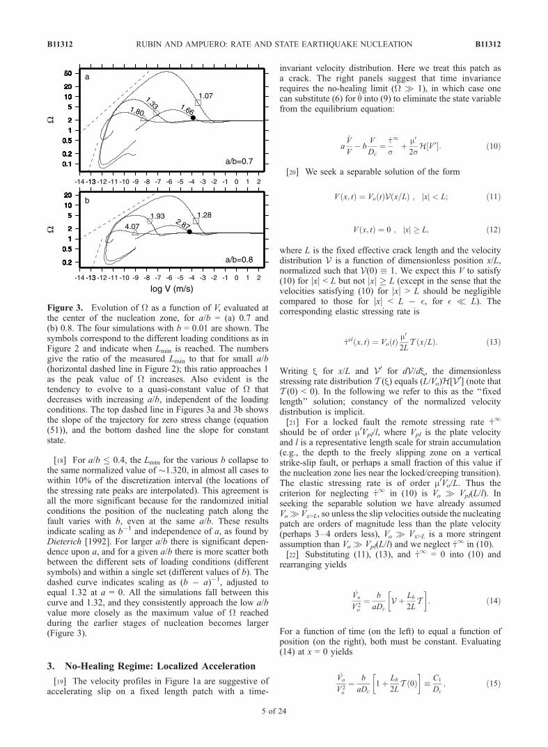
[18] For a/b � 0.4, the Lmin for the various b collapse tothe same normalized value of �1.320, in almost all cases towithin 10% of the discretization interval (the locations ofthe stressing rate peaks are interpolated). This agreement isall the more significant because for the randomized initialconditions the position of the nucleating patch along thefault varies with b, even at the same a/b. These resultsindicate scaling as b�1 and independence of a, as found byDieterich [1992]. For larger a/b there is significant depen-dence upon a, and for a given a/b there is more scatter bothbetween the different sets of loading conditions (differentsymbols) and within a single set (different values of b). Thedashed curve indicates scaling as (b � a)�1, adjusted toequal 1.32 at a = 0. All the simulations fall between thiscurve and 1.32, and they consistently approach the low a/bvalue more closely as the maximum value of W reachedduring the earlier stages of nucleation becomes larger(Figure 3).
3. No-Healing Regime: Localized Acceleration
[19] The velocity profiles in Figure 1a are suggestive ofaccelerating slip on a fixed length patch with a time-
invariant velocity distribution. Here we treat this patch asa crack. The right panels suggest that time invariancerequires the no-healing limit (W � 1), in which case onecan substitute (6) for _q into (9) to eliminate the state variablefrom the equilibrium equation:
a_V
V� b
V
Dc
¼ _ts
1þ m0
2sH V 0½ : ð10Þ
[20] We seek a separable solution of the form
V x; tð Þ ¼ Vo tð ÞV x=Lð Þ ; jxj < L; ð11Þ
V x; tð Þ ¼ 0 ; jxj � L; ð12Þ
where L is the fixed effective crack length and the velocitydistribution V is a function of dimensionless position x/L,normalized such that V(0) � 1. We expect this V to satisfy(10) for jxj < L but not jxj � L (except in the sense that thevelocities satisfying (10) for jxj > L should be negligiblecompared to those for jxj < L � �, for � � L). Thecorresponding elastic stressing rate is
_tel x; tð Þ ¼ Vo tð Þ m0
2LT x=Lð Þ: ð13Þ
Writing x for x/L and V0 for dV/dx, the dimensionlessstressing rate distribution T (x) equals (L/Vo)H[V0] (note thatT (0) < 0). In the following we refer to this as the ‘‘fixedlength’’ solution; constancy of the normalized velocitydistribution is implicit.[21] For a locked fault the remote stressing rate _t1
should be of order m0Vpl/l, where Vpl is the plate velocityand l is a representative length scale for strain accumulation(e.g., the depth to the freely slipping zone on a verticalstrike-slip fault, or perhaps a small fraction of this value ifthe nucleation zone lies near the locked/creeping transition).The elastic stressing rate is of order m0Vo/L. Thus thecriterion for neglecting _t1 in (10) is Vo � Vpl(L/l). Inseeking the separable solution we have already assumedVo� Vx>L, so unless the slip velocities outside the nucleatingpatch are orders of magnitude less than the plate velocity(perhaps 3–4 orders less), Vo � Vx>L is a more stringentassumption than Vo � Vpl(L/l) and we neglect _t1 in (10).[22] Substituting (11), (13), and _t1 = 0 into (10) and
rearranging yields
_Vo
V 2o
¼ b
aDc
V þ Lb
2LT
� �: ð14Þ
For a function of time (on the left) to equal a function ofposition (on the right), both must be constant. Evaluating(14) at x = 0 yields
_Vo
V 2o
¼ b
aDc
1þ Lb
2LT 0ð Þ
� �� C1
Dc
; ð15Þ
Figure 3. Evolution of W as a function of V, evaluated atthe center of the nucleation zone, for a/b = (a) 0.7 and(b) 0.8. The four simulations with b = 0.01 are shown. Thesymbols correspond to the different loading conditions as inFigure 2 and indicate when Lmin is reached. The numbersgive the ratio of the measured Lmin to that for small a/b(horizontal dashed line in Figure 2); this ratio approaches 1as the peak value of W increases. Also evident is thetendency to evolve to a quasi-constant value of W thatdecreases with increasing a/b, independent of the loadingconditions. The top dashed line in Figures 3a and 3b showsthe slope of the trajectory for zero stress change (equation(51)), and the bottom dashed line the slope for constantstate.
B11312 RUBIN AND AMPUERO: RATE AND STATE EARTHQUAKE NUCLEATION
5 of 24
B11312
with solution
Vo ¼ Vo 0ð Þ 1� t=t*ð Þ�1 ; t* � C�11 Dc=Vo 0ð Þ; ð16Þ
where, for C1 > 0, t* is the time of instability. That the slipvelocity increases as the inverse of the time to instability is ageneral property of single-degree-of-freedom systemsobeying equation (10) with _t proportional to V. For aspring-block slider with stiffness k and negligible remoteloading rate,
C1 ¼b
a1� kDc
bs
� �: ð17Þ
Thus a nucleating patch following the fixed length solutioncan be thought of as a single-degree-of-freedom systemwith an ‘‘effective stiffness’’ at the origin of k(0) = �(m0/2L)T (0), a result that follows immediately from (13) [seealso Dieterich, 1992, equation (25)].[23] Subtracting (15) from (14) yields the following
relation between the normalized velocity and stressing ratedistributions:
V xð Þ ¼ 1� Lb
2LT xð Þ � T 0ð Þ½ : ð18Þ
Given any value of the intrinsic length scale Lb, equation(18) enables one to compute V and T for any L. However,requiring that the nucleation zone neither expand norcontract also requires that the stresses at the tip of thecorresponding ‘‘effective crack’’ be finite (that is, that thestress intensity factor K at the tip equal zero), and this fixesL to a unique value, which we write as Ln. An equationanalogous to (18) with the K = 0 constraint also arises in thecontext of a uniformly stressed slip-weakening crack in thelarge-scale yielding regime [Chen and Knopoff, 1986]. Notethat because (18) is independent of a, so too are V, T , andLn; a controls the time of instability through equations (15)and (16).[24] To solve (18) numerically, the Hilbert transform of
the velocity gradients can be inverted to determine V interms of the stressing rate (symmetric about the origin)[e.g.,Spence and Sharp, 1895]:
V xð Þ ¼ � 2
pm0
Z 1
0
ln
ffiffiffiffiffiffiffiffiffiffiffiffiffi1� x2
p�
ffiffiffiffiffiffiffiffiffiffiffiffiffi1� s2
pffiffiffiffiffiffiffiffiffiffiffiffiffi1� x2
pþ
ffiffiffiffiffiffiffiffiffiffiffiffiffi1� s2
p
����������T sð Þds: ð19Þ
If T is approximated as piecewise linear over M segmentsalong the half crack then the integral can be evaluatedanalytically. Assuming a continuous stress distribution leadsto M + 1 unknown stress values, which we determine bysatisfying (18) at the center of each segment as well as at theorigin (where V � 1). A normalized K is determinedanalytically from the same symmetric, continuous, andpiecewise linear stress distribution using [Lawn, 1993]
K ¼ 2
pL1=2
Z 1
0
T xð Þffiffiffiffiffiffiffiffiffiffiffiffiffi1� x2
p dx: ð20Þ
[25] Consistent with the results of Chen and Knopoff[1986], we find by iteration that enforcing K = 0 requiresLb/L = 0.7260, or
Ln ¼ 1:3774Lb ð21Þ
(10% larger than the value of 1.25Lb proposed by Dieterich[1992]), and fixes T (0) = �1.7132 (compared to �1 for auniform stress drop). For these values the constant C1 in(15) is indeed positive, as is required for instability:
C1 ¼ 0:3781b
a: ð22Þ
The stress distribution satisfying (18) for smaller L yieldsK > 0, and if imposed as an initial condition would cause theeffective crack to grow, while the stress distribution forlarger L yields K < 0 (the direction of slip near the crackends is opposite to that at the center), which would require achange in sign of the ambient stress.[26] In Figure 4 we compare the distributions of V and T
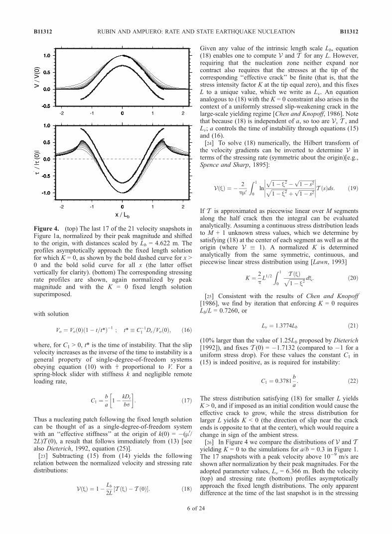
yielding K = 0 to the simulations for a/b = 0.3 in Figure 1.The 17 snapshots with a peak velocity above 10�9 m/s areshown after normalization by their peak magnitudes. For theadopted parameter values, Ln = 6.366 m. Both the velocity(top) and stressing rate (bottom) profiles asymptoticallyapproach the fixed length distributions. The only apparentdifference at the time of the last snapshot is in the stressing
Figure 4. (top) The last 17 of the 21 velocity snapshots inFigure 1a, normalized by their peak magnitude and shiftedto the origin, with distances scaled by Lb = 4.622 m. Theprofiles asymptotically approach the fixed length solutionfor which K = 0, as shown by the bold dashed curve for x >0 and the bold solid curve for all x (the latter offsetvertically for clarity). (bottom) The corresponding stressingrate profiles are shown, again normalized by peakmagnitude and with the K = 0 fixed length solutionsuperimposed.
B11312 RUBIN AND AMPUERO: RATE AND STATE EARTHQUAKE NUCLEATION
6 of 24
B11312
rate at the crack tips, which are well defined in the fixedlength solution but not in the numerical simulation. Relatedto this, perhaps, is a very consistent 4.35% differencebetween the crack length given by (21) and the (smaller)distance between the stressing rate peaks in the numericalsimulations that we do not consider further.
3.1. Applicability of the No-Healing Limit
[27] Assuming W � 1 when the fixed length solution isfirst approached (as in Figures 1b and 1d), we can substitutethe velocity history from (11) and (16) into (6) for _q todetermine when the no-healing approximation remainsvalid. Integrating equation (6), multiplying by V(x, t)/V(x,0), and making use of (16) yields
W x; tð ÞW x; 0ð Þ ¼
Vo tð ÞVo 0ð Þ
� �1�V xð Þ=C1
: ð23Þ
Thus W is an increasing function of velocity for V(x)/C1 < 1,and a decreasing function for V(x)/C1 > 1. Equation (6)remains a valid approximation until instability (V =1) onlyfor V(x)/C1 � 1. Because V is maximal at the crack centerand tends to zero at x/L = ±1, W continually increases nearthe crack ends and the no-healing approximation is firstviolated (if ever) at x = 0 (Figure 1). Substituting V(0) = 1and equation (22) for C1 into (23), (6) remains valid untilinstability only for
C1 > 1 ¼) a
b< 0:3781: ð24Þ
[28] This result explains many of the pertinent features ofFigures 1 and 2. The fixed length solution places norestrictions on a/b, not even that a < b; it requires only thatW � 1. When equation (24) is satisfied, W increasesmonotonically and all our simulations evolve to a nucleation
length equal to (96% of) that given by (21). As (24) isprogressively violated, W decreases more and more rapidlyat the crack center (by 0.3 decades for each decade increasein V for a/b = 0.5, compared to 1.4 decades for each decadeincrease in V for a/b = 0.9). If W is sufficiently large asnucleation localizes, the fixed length solution may remainnearly valid over a velocity increase of many orders ofmagnitude even for a/b > 0.5. This is clearly seen in ourFigure 1c and in Figures 4 and 5 of Dieterich [1992]. Thedegree to which the fixed length solution accurately predictsthe nucleation length for a/b > 0.3781, and the variable Lmin
for a/b ^ 0.5 in Figure 2, presumably reflect how theloading conditions control W upon localization.[29] We note that retaining a uniform and constant remote
stressing rate leads to a more complicated equation for Vo(t)analogous to equation (26) of Dieterich [1992]. This equa-tion tends to our equation (16) provided t = 0 is defined at atime when _t1 � j _telj. A nonzero _t1 does not influence thevelocity distribution V because it drops out in the derivationof equation (18).
3.2. Relation to Rate and State Spring-Block Slidersand Slip-Weakening Faults
[30] Ranjith and Rice [2003] found that spring-blocksliders obeying equations (1) and (3) could go unstableonly for spring stiffnesses less than a critical value kcr = (b�a)s/Dc, even for arbitrarily large perturbations from steadystate (unstable in the sense that the quasi-static equationslead to infinite velocities). For an elastic continuum theeffective stiffness should be nearly inversely proportional toL, so this result might seem to contradict the assertion thatthe nucleation length scales as b�1 rather than (the appar-ently larger) (b � a)�1 when (24) is satisfied. To explorethis further, we can summarize from equations (15) and (24)the conditions for instability of the fixed length solution as
Instability in the limit W � 1 (C1 > 0)
1þ Lb
2LT 0ð Þ > 0: ð25Þ
W � 1 until instability (C1 � 1)
1þ Lb
2LT 0ð Þ � a
b: ð26Þ
It is immediately apparent that for a, b > 0 the second ofthese criteria is more stringent than the first. In terms of theeffective stiffness at the crack center k(0) = �(m0/2L)T (0),criteria (25) and (26) become respectively k(0) < bs/Dc andk(0) � (b � a)s/Dc (recall that Lb � m0Dc/bs). Thus there isno inconsistency with the results of Ranjith and Rice. Forthe fixed length crack, the constraint K = 0 gives rise to aneffective stiffness that is low enough for W to increase untilinstability, provided a/b is sufficiently small.[31] It is worth emphasizing that the K = 0 solution to
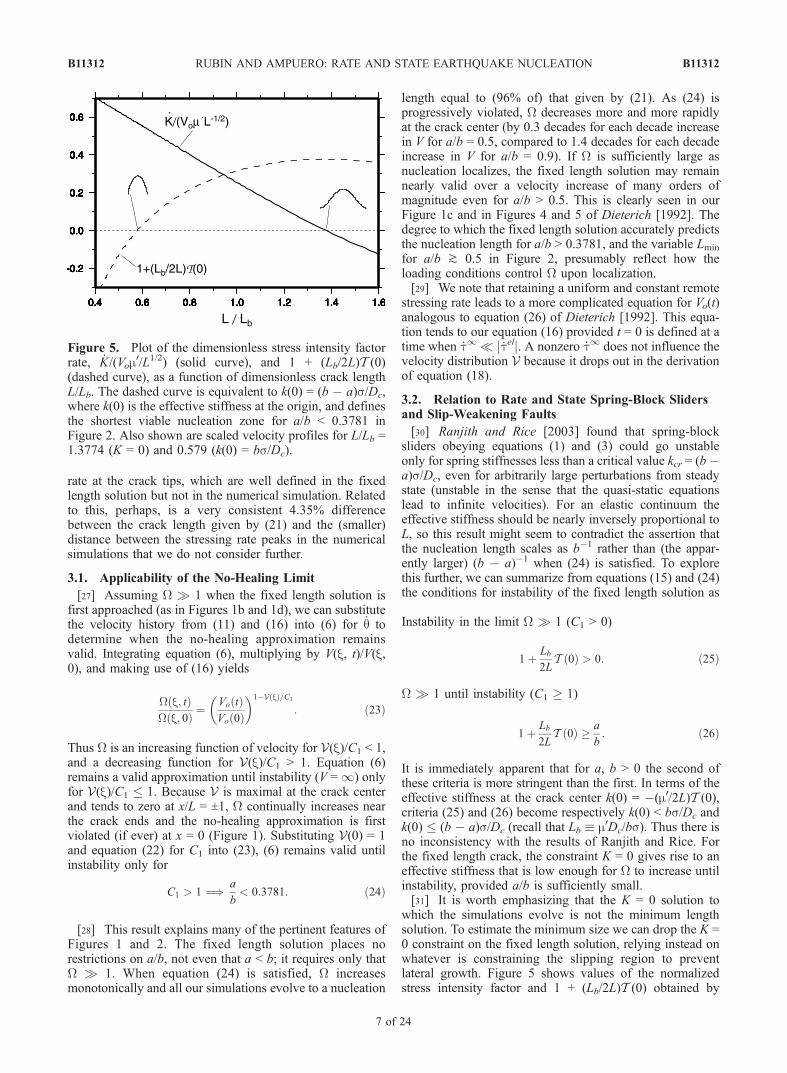
which the simulations evolve is not the minimum lengthsolution. To estimate the minimum size we can drop the K =0 constraint on the fixed length solution, relying instead onwhatever is constraining the slipping region to preventlateral growth. Figure 5 shows values of the normalizedstress intensity factor and 1 + (Lb/2L)T (0) obtained by
Figure 5. Plot of the dimensionless stress intensity factorrate, _K/(Vom
0/L1/2) (solid curve), and 1 + (Lb/2L)T (0)(dashed curve), as a function of dimensionless crack lengthL/Lb. The dashed curve is equivalent to k(0) = (b � a)s/Dc,where k(0) is the effective stiffness at the origin, and definesthe shortest viable nucleation zone for a/b < 0.3781 inFigure 2. Also shown are scaled velocity profiles for L/Lb =1.3774 (K = 0) and 0.579 (k(0) = bs/Dc).
B11312 RUBIN AND AMPUERO: RATE AND STATE EARTHQUAKE NUCLEATION
7 of 24
B11312
solving (18) for a range of L/Lb. The zero crossing of the 1 +(Lb/2L)T (0) curve indicates the minimum L satisfying (25),and the value of that curve shows, for each L, the maximumvalue of a/b satisfying (26). Thus along the 1 + (Lb/2L)T (0)curve, k(0) = (b � a)s/Dc.[32] This k(0) = (b � a)s/Dc curve is drawn as the dotted
line in Figure 2. It indicates, as a function of a/b, theshortest fixed length nucleation zone satisfying (26). At a =0 this minimum length coincides with the universal nucle-ation length of 0.579Lb found byUenishi and Rice [2003] forlinear slip-weakening behavior. In a sense this is comforting;for a = 0 equation (10) reverts to pure slip weakening withweakening rateW=�dt/dd=� _t/V= bs/Dc.Mathematically,for 1 + (Lb/2L)T (0) = 0 our equation (18) for V is identical toequation (12) of Uenishi and Rice for the velocity distributionof a nucleating crack poised at the stable/unstable transition.Physically, however, the situations in which these velocitydistributions arise seem quite different: Acceleration of apinned crack with K > 0 in our case; the onset of unstablegrowth for a (previously) stably expanding crack satisfyingK = 0 in theirs. Our case is conceptually more similar, but stillnot identical, to that of Dascalu et al. [2000], who found thesame minimum length for a fixed length elastodynamic crackwith linear slip-weakening behavior, stressed uniformly at thepeak strength.[33] In a numerical study of rate-and-state friction,
Lapusta and Rice [2002] found nucleation lengths that
agreed with the slip-weakening (a = 0) estimate of Uenishiand Rice for a < 10�6 but that ‘‘more than doubled’’ for a =10�4. From Figure 2 it appears that this reflects a transitionfrom the 1 + (Lb/2L)T (0) = 0 solution to the K = 0 solutionof equation (18). We found no nucleation lengths lyingalong the dotted curve in Figure 2; presumably this wouldrequire larger stress barriers (to pin the crack) than wesimulated.
4. Constant-Weakening Regime: Quasi-StaticCrack Growth
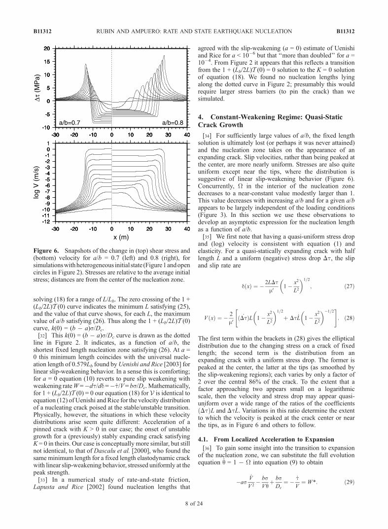
[34] For sufficiently large values of a/b, the fixed lengthsolution is ultimately lost (or perhaps it was never attained)and the nucleation zone takes on the appearance of anexpanding crack. Slip velocities, rather than being peaked atthe center, are more nearly uniform. Stresses are also quiteuniform except near the tips, where the distribution issuggestive of linear slip-weakening behavior (Figure 6).Concurrently, W in the interior of the nucleation zonedecreases to a near-constant value modestly larger than 1.This value decreases with increasing a/b and for a given a/bappears to be largely independent of the loading conditions(Figure 3). In this section we use these observations todevelop an asymptotic expression for the nucleation lengthas a function of a/b.[35] We first note that having a quasi-uniform stress drop
and (log) velocity is consistent with equation (1) andelasticity. For a quasi-statically expanding crack with halflength L and a uniform (negative) stress drop Dt, the slipand slip rate are
d xð Þ ¼ � 2LDtm0
1� x2
L2
� �1=2
; ð27Þ
V xð Þ ¼ � 2
m0_Dtð ÞL 1� x2
L2
� �1=2
þ Dt _L 1� x2
L2
� ��1=2" #
: ð28Þ
The first term within the brackets in (28) gives the ellipticaldistribution due to the changing stress on a crack of fixedlength; the second term is the distribution from anexpanding crack with a uniform stress drop. The former ispeaked at the center, the latter at the tips (as smoothed bythe slip-weakening regions); each varies by only a factor of2 over the central 86% of the crack. To the extent that afactor approaching two appears small on a logarithmicscale, then the velocity and stress drop may appear quasi-uniform over a wide range of the ratios of the coefficients_Dtð ÞL and Dt _L. Variations in this ratio determine the extent
to which the velocity is peaked at the crack center or nearthe tips, as in Figure 6 and others to follow.
4.1. From Localized Acceleration to Expansion
[36] To gain some insight into the transition to expansionof the nucleation zone, we can substitute the full evolutionequation _q = 1 � W into equation (9) to obtain
�as_V
V 2� bsVq
þ bsDc
¼ � _tV
¼ W*: ð29Þ
Figure 6. Snapshots of the change in (top) shear stress and(bottom) velocity for a/b = 0.7 (left) and 0.8 (right), forsimulationswithheterogeneous initial state (Figure1andopencircles in Figure 2). Stresses are relative to the average initialstress; distances are from the center of the nucleation zone.
B11312 RUBIN AND AMPUERO: RATE AND STATE EARTHQUAKE NUCLEATION
8 of 24
B11312
Here W* may be interpreted as an ‘‘effective’’ or bulk slip-weakening rate, with contributions from the direct effect(as _V /V2; essentially a nonlinear viscosity), fault healing(bs/Vq), and slip weakening (bs/Dc). In the no-healing limitthe bs/Vq term is negligible, and using the separableformulation V = Vo(t)V(x) (equation (11)) we have
� asV xð Þ
_Vo
V 2o
þ bsDc
¼ W*: ð30Þ
Substituting the K = 0 fixed length result _Vo/Vo2 =
0.3781(b/aDc), (30) indicates a bulk weakening rate of0.6219(bs/Dc) at the crack center (V = 1). Near the cracktips, where V approaches zero, the bs/Dc term is negligibleand the bulk ‘‘weakening’’ rate is negative. This is requiredto satisfy the K = 0 criterion for a stationary crack. Inessence, near the crack center the evolution effectdominates and the fault weakens during the approach toinstability, while near the ends the direct effect dominatesand the fault strengthens (as can be seen, for example, bydividing equation (23) by V(x, t)/V(x, 0)).[37] Once W approaches unity near the crack center, the
healing term is no longer negligible and the bulk weakeningrate decreases. In the limit of zero weakening, elasticityrequires that further slip at the crack center be accompaniedby an increase in crack length. However, this is readilyachieved, since the stresses near the crack tips are verylarge. Zero acceleration at the crack center, coupled withcontinued large accelerations at the tips, ensures that crackexpansion occurs simultaneously with slip at the center. Onemight expect qualitatively similar results for a reduced butfinite weakening rate at the crack center, and an analogywith nonlinear slip-weakening behavior indicates that this isthe case. If the slip-weakening curve has an inflection point,such that the largest weakening rate occurs at a finite slipdistance, then localization will progress for as long as theweakening rate is increasing, but expansion ensues aftersome portion of the nucleation zone passes through theinflection [Suo et al., 1992; Ampuero, 2002]. The minimumnucleation length in this case (analogous to our Lmin) issensitive to the maximum slope of the friction law, a resultthat follows from dimensional analysis. The transition fromlocalization to expansion becomes sharper as the differencein weakening rates across the inflection becomes morepronounced. The main qualitative difference between theslip-weakening and rate-and-state cases lies in how slow(quasi-static) motion is enforced. In the slip-weakening casestability requires a reduction in driving stress with slip,while in rate-and-state friction the nonlinear viscosity intro-duced by the direct effect allows for quasi-static accelerationof slip under constant load.
4.2. Nucleation Length
[38] We start from the observation of a near-constant W inthe interior of the nucleation zone, and note that this implies_V /V + _q/q = 0. With _q = 1 � W, this leads to
_V
V 2¼ 1� W�1
Dc
� C1
Dc
: ð31Þ
As this is identical in form to equation (15), we have
V ¼ V 0ð Þ 1� t=t*ð Þ�1; t* � C�11 Dc=V 0ð Þ : ð32Þ
That is, the slip velocity again increases as the inverse timeto instability, but with C1 now given by (31). This result isconfirmed by the numerical simulations in that plots oflog(V) versus log(t* � t) for all the simulations with thesame a/b (meaning nearly the same W) are indistinguishableover the time window that W is � constant, and have theslope and intercept predicted by (32). As the no-healingapproximation was used by Dieterich [1994] to deriveOmori-law-type aftershock statistics from rate and statefriction, the fact that the constant-weakening limit sharesthis property suggests that similar behavior might be foundin this regime as well, although more work is certainlynecessary to determine if this is so.[39] One must also ask what aspect of the underlying
mechanics gives rise to the near-constant W. Substituting Wfor Vq/Dc in equation (1) yields
ts¼ f *þ aln
V
V*þ b ln Wð Þ � ln
V
V*
� �: ð33Þ
This is offset from the steady state curve by bln(W), so to theextent that W is constant differentiating with respect to timegives the same result as for steady state sliding:
_ts¼ a� bð Þ
_V
V: ð34Þ
From equilibrium, once nucleation is well underway and_t1 is negligible, the effective elastic stiffness k* may bedetermined by dividing equation (34) by V and using(31):
k* ¼ � _tel
V� � _t
V¼ s b� að Þ
Dc
1� W�1� �
: ð35Þ
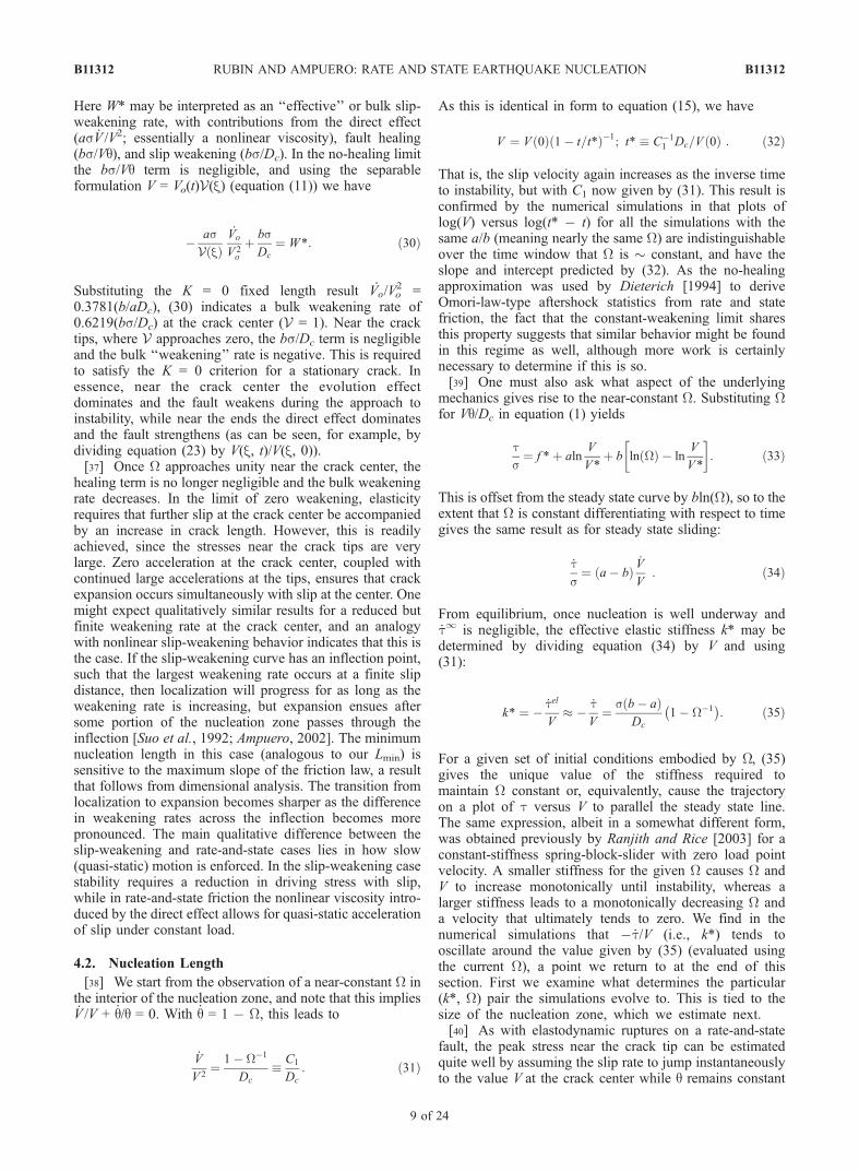
For a given set of initial conditions embodied by W, (35)gives the unique value of the stiffness required tomaintain W constant or, equivalently, cause the trajectoryon a plot of t versus V to parallel the steady state line.The same expression, albeit in a somewhat different form,was obtained previously by Ranjith and Rice [2003] for aconstant-stiffness spring-block-slider with zero load pointvelocity. A smaller stiffness for the given W causes W andV to increase monotonically until instability, whereas alarger stiffness leads to a monotonically decreasing W anda velocity that ultimately tends to zero. We find in thenumerical simulations that � _t/V (i.e., k*) tends tooscillate around the value given by (35) (evaluated usingthe current W), a point we return to at the end of thissection. First we examine what determines the particular(k*, W) pair the simulations evolve to. This is tied to thesize of the nucleation zone, which we estimate next.[40] As with elastodynamic ruptures on a rate-and-state
fault, the peak stress near the crack tip can be estimatedquite well by assuming the slip rate to jump instantaneouslyto the value V at the crack center while q remains constant
B11312 RUBIN AND AMPUERO: RATE AND STATE EARTHQUAKE NUCLEATION
9 of 24
B11312
(Figure 7). Subtracting (33) from (1) and simplifying, thepeak-to-residual stress drop Dtp�r is
Dtp�r ¼ sblnVqiDcW
� �; ð36Þ
where qi denotes the value of q just prior to the arrival of thetip. Given the abrupt jump in velocity, near the tip W � 1(e.g., Figure 1f). Assuming V is maintained constant, as qevolves the effective slip-weakening rate W* (from equation(29) with _V = 0) is bs/Dc, at least until near-steady stateconditions are reached. The effective slip-weakeningdistance dc is then
dc ¼Dtp�r
W*¼ Dcln
V qiDcW
� �: ð37Þ
For W = 1 this reduces to the result of Bizzarri and Cocco[2003] that the effective slip-weakening distance is largerthan Dc by the logarithm of the ratio of qi to the steady stateq at seismic slip speeds (see also Dieterich and Kilgore[1996]).[41] For a constant slip-weakening rate the fracture energy
Gc is 0.5Dtp�rdc, so combining (36) and (37) yields
Gc ¼sbDc
2ln
VqiDcW
� �� �2: ð38Þ
For an equilibrium crack Gc is balanced by the reductionin mechanical energy per increment of crack length, givenby
G ¼ p2
L
m0Dt2; ð39Þ
where Dt is the ambient-to-residual stress drop [Lawn,1993]. To estimate Dt, we can write the initial stress asequivalent to that due to slip at a hypothetical (notnecessarily realized) steady state background velocity Vbg.Substituting this into (5) and subtracting (33),
G ¼ p2
L
m0�sblnWþ s b� að Þ ln V
Vbg
� �2: ð40Þ
Equating G with Gc, the equilibrium crack length Lc isfound to be
Lc ¼1
pb
b� a
� �2
Lbln V
Dc=qi� lnW
ln VVbg
� bb�a
lnW
" #2: ð41Þ
For W a constant near 1, the bracketed expression in (41)approaches 1 in the limit V � Vbg, Dc/qi. In all oursimulations Dc/qi > Vbg because prior to the arrival of thecrack tip qi had been reduced from the background value(either because the nucleation zone had been larger or as aresult of the approaching stress concentration); this seemslikely to be a rather general result. Thus the bracketedexpression asymptotically approaches 1 from below, whichexplains the slow (and slowing) expansion of thenucleation zones in Figure 6. Writing L1 for this limitingvalue of Lc,
L1 � 1
pb
b� a
� �2
Lb : ð42Þ
The dependence on [b/(b � a)]2 implies that the nucleationlength can grow to be much larger than Ln as a approachesb (e.g., by factors of 10 and 100 for a/b = 0.85 and 0.95,respectively).[42] Because the crack has a near-constant stress drop
and is growing only slowly, the effective stiffness is aquasi-constant �m0/2L1. Setting this equal to the rightside of (35) and using the definition of C1 from (31) weobtain
C1 � 1� W�1 � p2
b� a
b; ð43Þ
implying that the interior of the nucleation zone approachessteady state (W = 1) more and more closely as a approachesb. Combining this result with (32), the time remaining toinstability t* � t is
t*� t ¼ 2
pb
b� a
Dc
V tð Þ ; ð44Þ
Figure 7. Normalized shear stress change (thin lines),Dt/bs, as a function of normalized slip, d/Dc, for threesnapshots during the crack-like expansion of a nucleationzone for a/b = 0.8 (as in Figure 6 but for a localized loadingrate on an initially steady state surface; solid circles inFigures 2 and 3). The indicated slip is that which hasaccumulated since the beginning of the simulation minusthat at the ‘‘crack tip’’ (the location of the peak stress) inthe final snapshot (the curve with the largest peak stress). Theright endpoints of the curves correspond to the center of thenucleation zone. The bold line indicates a slip-weakening rateof bs/Dc, drawn with the peak-to-residual and ambient-to-residual stress drops given by (36) and (40), evaluated usingVand W (at the crack center) and qi (at the crack tip) extractedfrom the final snapshot, and shows good agreement with thenumerical simulation. The dashed line shows the bulk slipweakening rate W* at the center of the nucleation zone overthe time window that W is quasi-constant.
B11312 RUBIN AND AMPUERO: RATE AND STATE EARTHQUAKE NUCLEATION
10 of 24
B11312
where V(t) is the current slip speed in the interior of thenucleation zone. The corresponding result for the no-healinglimit is (combining (22) and (16))
t*� t ¼ 2:645a
b
Dc
V tð Þ : ð45Þ
Equations (44) and (45) show that in the no-healing limitthe time to instability is of order Dc/V(t) for a/b � 1, but thatin the constant-weakening limit this time becomes un-bounded (the two estimates are nearly identical for a/b =0.5, as are the respective estimates of nucleation length).[43] In a practical sense, we are interested in the size of
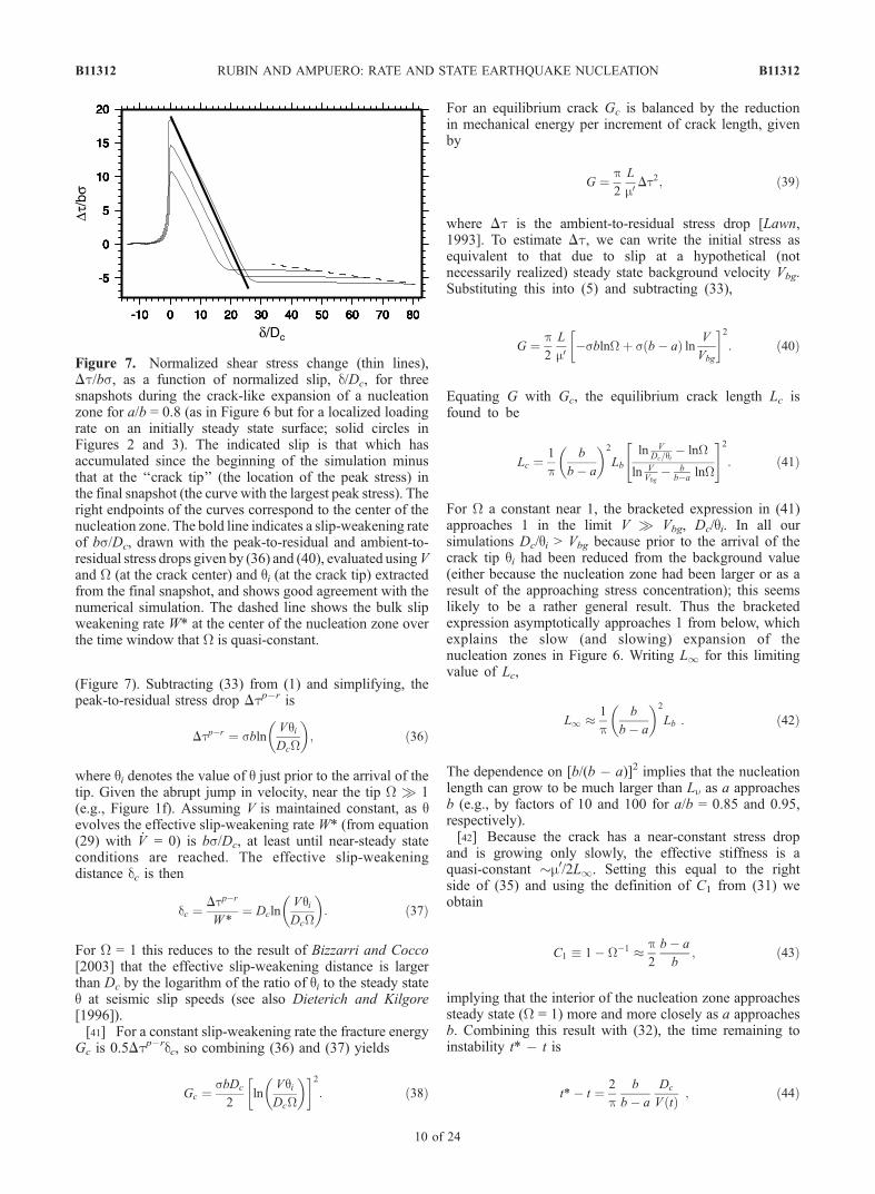
the nucleation zone as it begins to radiate seismic energy.We define L0.1 to be the nucleation length at the time thatthe maximum slip speed reaches 0.1 m/s, as this is roughlythe velocity at which elastodynamics becomes important
(Appendix A2). Figure 8 shows that the L1 defined in (42)provides a good approximation to the values of L0.1 deter-mined from the simulations. The discrepancy of some tensof percent in the case of the heterogeneous initial con-ditions (open circles) is attributable at least in part to thelimiting length not yet being reached. The bottom panel inFigure 8 compares the value of 1 � W�1 at the center ofthe nucleation zone to the prediction from (43), again at avelocity of 10�1 m/s. In this case the extent of theagreement is perhaps surprising, at least for a/b ] 0.8,in that (43) assumes that L1 has already been reached.This is not the case, for example, with the open circles fora/b = 0.7 and 0.8. In fact, the agreement is such as to leadus to suspect that there may be a more direct route to thesame result (note also the good fit at a/b = 0.5, despite thesuggestion from the top panel that equation (42) may notbe applicable at this a/b).[44] Further insight into the crack expansion phase of
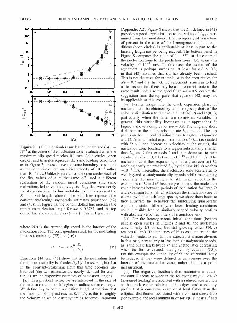
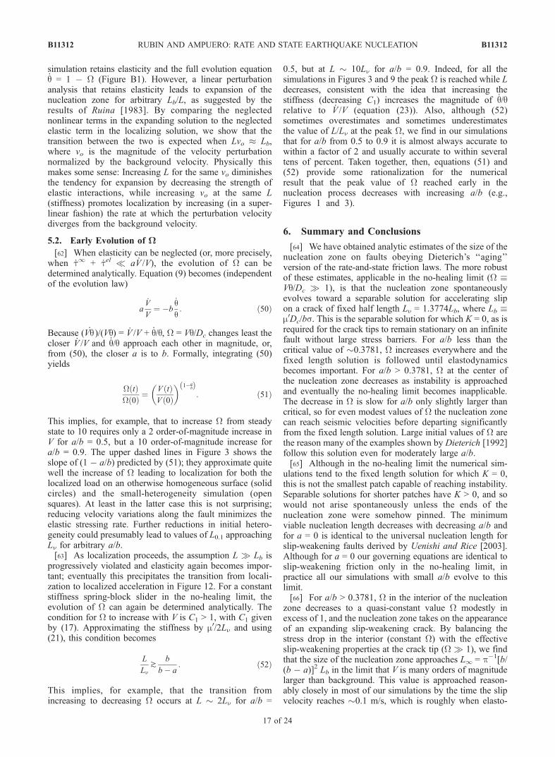
nucleation can be obtained by comparing snapshots of thevelocity distribution to the evolution of W(0, t) and k*(0, t),particularly when the latter are somewhat variable. Ingeneral this variability increases as a approaches b;Figure 9 shows examples for a/b = 0.9. The long and shortdark bars in the left panels indicate L1 and Ln. The toppanels are for the peaked initial stress (triangles in Figures 2and 8). After an initial expansion out to L > L1 (associatedwith W < 1 and decreasing velocities at the origin), thenucleation zone localizes to a region substantially smallerthan L1 as W first exceeds 2 and then decreases to nearsteady state (for V(0, t) between �10�10 and 10�7 m/s). Thenucleation zone then expands again at a quasi-constant W,reaching nearly the predicted L1 by the time V(0, t) reaches�10�4 m/s. Thereafter, the nucleation zone accelerates towell beyond elastodynamic slip speeds while maintainingessentially the same length. At still larger velocities theexcursions of W and k* become greater, and the nucleationzone alternates between periods of localization for large Wand expansion for small W. Although the simulations are ofcourse invalid at such large speeds, we show them becausethey illustrate the behavior the underlying quasi-staticequations; stated differently, different loading conditionscould plausibly lead to similarly shaped velocity profileswith absolute velocities orders of magnitude less.[45] For the heterogeneous initial conditions (bottom
panels; open circles in Figures 2 and 8), the nucleationzone is only 2/3 of L1 but still growing when V(0, t)reaches 0.1 m/s. The tendency of k* to oscillate around thevalue kW needed to maintain the expected W is more obviousin this case, particularly at less than elastodynamic speeds,as is the phase lag between k* and W (the latter decreasingwhen the former exceeds that given by equation (35)).For this example the variability of W and k* would likelybe reduced if they were defined as an average over theinterior of the nucleation zone, rather than as a pointmeasurement.[46] The negative feedback that maintains a quasi-
constant W seems to work in the following way: A low W(increased healing) is associated with a reduced accelerationat the crack center relative to the edges, and a velocityprofile that is concave-upward or at least flatter than theelliptical distribution associated with a constant stress drop(for example, the local minima in k* for V(0, t) near 102 and
Figure 8. (a) Dimensionless nucleation length and (b) 1 �W�1 at the center of the nucleation zone, evaluated when themaximum slip speed reaches 0.1 m/s. Solid circles, opencircles, and triangles represent the same loading conditionsas in Figure 2; crosses have the same boundary conditionsas the solid circles but an initial velocity of 10�11 ratherthan 10�9 m/s. Unlike Figure 2, for the open circles each ofthe five values of b at the same a/b used a differentrealization of the random initial conditions (the samerealizations led to values of L0.1 and W0.1 that were nearlyindistinguishable). The horizontal dashed lines represent theK = 0 fixed length solution. The solid lines represent theconstant-weakening asymptotic estimates (equations (42)and (43)). In Figure 8a, the bottom dotted line indicates theminimum nucleation length for a/b < 0.3781, and the topdotted line shows scaling as (b � a)�1, as in Figure 2.
B11312 RUBIN AND AMPUERO: RATE AND STATE EARTHQUAKE NUCLEATION
11 of 24
B11312
104 m/s in Figures 9a–9c). This reduces the effectivestiffness (the crack edges load the center), which, followingRanjith and Rice [2003] leads to an increasing W. Con-versely, if W becomes too large for the current stiffness,healing becomes less important and the center of thenucleation zone accelerates more than in the constant Wcase. If this acceleration leaves the neighboring regionsbehind, the effective stiffness increases, which in turndecreases W (for example, the local maxima in k* forV(0, t) near 100 and 103 m/s in the top row).[47] In general we find increasing complexity in the
velocity profiles during nucleation, and increasingly largeexcursions ofW from the expected value, with increasing a/b.Plausibly this is because the time to instability in theconstant-weakening regime becomes unbounded as a/bapproaches 1 (equation (44)), allowing some other mode
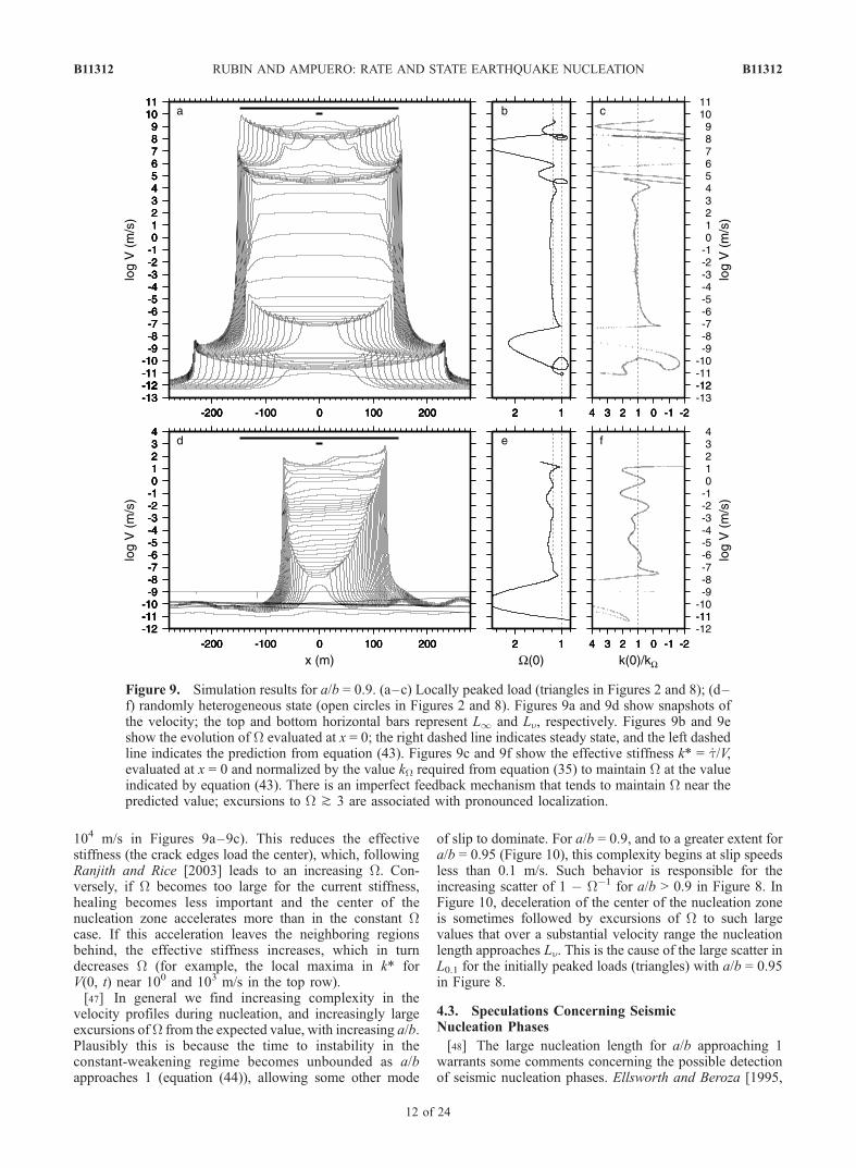
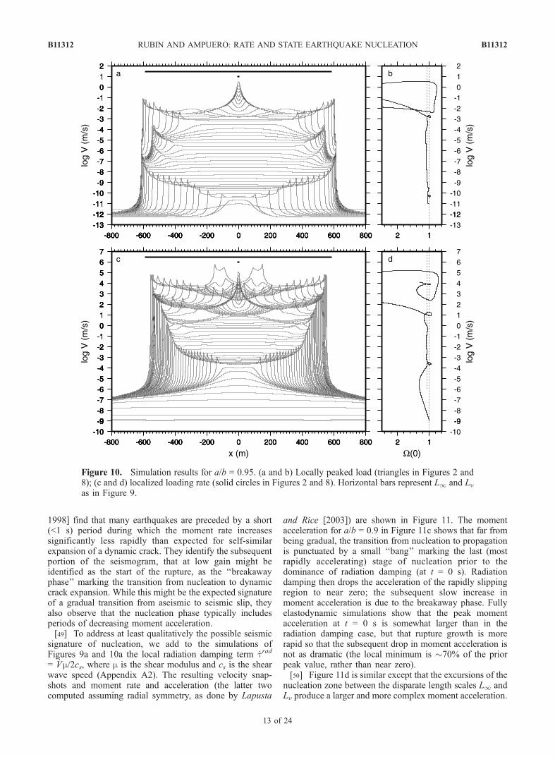
of slip to dominate. For a/b = 0.9, and to a greater extent fora/b = 0.95 (Figure 10), this complexity begins at slip speedsless than 0.1 m/s. Such behavior is responsible for theincreasing scatter of 1 � W�1 for a/b > 0.9 in Figure 8. InFigure 10, deceleration of the center of the nucleation zoneis sometimes followed by excursions of W to such largevalues that over a substantial velocity range the nucleationlength approaches Ln. This is the cause of the large scatter inL0.1 for the initially peaked loads (triangles) with a/b = 0.95in Figure 8.
4.3. Speculations Concerning SeismicNucleation Phases
[48] The large nucleation length for a/b approaching 1warrants some comments concerning the possible detectionof seismic nucleation phases. Ellsworth and Beroza [1995,
Figure 9. Simulation results for a/b = 0.9. (a–c) Locally peaked load (triangles in Figures 2 and 8); (d–f) randomly heterogeneous state (open circles in Figures 2 and 8). Figures 9a and 9d show snapshots ofthe velocity; the top and bottom horizontal bars represent L1 and Ln, respectively. Figures 9b and 9eshow the evolution of W evaluated at x = 0; the right dashed line indicates steady state, and the left dashedline indicates the prediction from equation (43). Figures 9c and 9f show the effective stiffness k* = _t/V,evaluated at x = 0 and normalized by the value kW required from equation (35) to maintain W at the valueindicated by equation (43). There is an imperfect feedback mechanism that tends to maintain W near thepredicted value; excursions to W ^ 3 are associated with pronounced localization.
B11312 RUBIN AND AMPUERO: RATE AND STATE EARTHQUAKE NUCLEATION
12 of 24
B11312
1998] find that many earthquakes are preceded by a short(<1 s) period during which the moment rate increasessignificantly less rapidly than expected for self-similarexpansion of a dynamic crack. They identify the subsequentportion of the seismogram, that at low gain might beidentified as the start of the rupture, as the ‘‘breakawayphase’’ marking the transition from nucleation to dynamiccrack expansion. While this might be the expected signatureof a gradual transition from aseismic to seismic slip, theyalso observe that the nucleation phase typically includesperiods of decreasing moment acceleration.[49] To address at least qualitatively the possible seismic
signature of nucleation, we add to the simulations ofFigures 9a and 10a the local radiation damping term _trad
= _Vm/2cs, where m is the shear modulus and cs is the shearwave speed (Appendix A2). The resulting velocity snap-shots and moment rate and acceleration (the latter twocomputed assuming radial symmetry, as done by Lapusta
and Rice [2003]) are shown in Figure 11. The momentacceleration for a/b = 0.9 in Figure 11c shows that far frombeing gradual, the transition from nucleation to propagationis punctuated by a small ‘‘bang’’ marking the last (mostrapidly accelerating) stage of nucleation prior to thedominance of radiation damping (at t = 0 s). Radiationdamping then drops the acceleration of the rapidly slippingregion to near zero; the subsequent slow increase inmoment acceleration is due to the breakaway phase. Fullyelastodynamic simulations show that the peak momentacceleration at t = 0 s is somewhat larger than in theradiation damping case, but that rupture growth is morerapid so that the subsequent drop in moment acceleration isnot as dramatic (the local minimum is �70% of the priorpeak value, rather than near zero).[50] Figure 11d is similar except that the excursions of the
nucleation zone between the disparate length scales L1 andLn produce a larger and more complex moment acceleration.
Figure 10. Simulation results for a/b = 0.95. (a and b) Locally peaked load (triangles in Figures 2 and8); (c and d) localized loading rate (solid circles in Figures 2 and 8). Horizontal bars represent L1 and Lnas in Figure 9.
B11312 RUBIN AND AMPUERO: RATE AND STATE EARTHQUAKE NUCLEATION
13 of 24
B11312
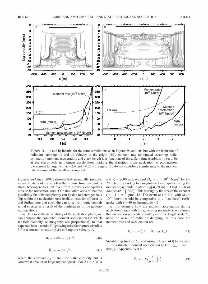
Lapusta and Rice [2003] showed that an initially irregularmoment rate could arise when the rupture front encountersstress heterogeneities left over from previous earthquakesoutside the nucleation zone. Our simulation adds to that thepossibility that this complexity can be due to heterogeneousslip within the nucleation zone itself, at least for a/b near 1,and furthermore that such slip can arise from quite smoothinitial stresses as a result of the nonlinearity of the govern-ing equations.[51] To assess the detectability of the nucleation phase, we
can compare the computed moment acceleration (to whichfar-field velocity seismograms are proportional) to thatexpected for a ‘‘standard’’ (growing) circular rupture of radiusl. For a constant stress drop Dt and rupture velocity Vr ,
Mo ¼ mpl2d ¼ a1Dtl3; ð46Þ
�Mo ¼ 6a1DtV 2r l ; ð47Þ
where the constant a1 = 16/7 for static elasticity but issomewhat smaller at large rupture speeds. For Dt = 3 MPa
and Vr = 2600 m/s, we find �Mo � 5 � 1015 Nm/s2 for l =20 m (corresponding to a magnitude 1 earthquake, using themoment-magnitude relation log[Mo/N m] = 1.0M + 9.8 ofAbercrombie [1996]). This is roughly the size of the event att = �1 s in Figure 11d. The event at t = 0 s, with �Mo =1016 Nm/s2, would be comparable to a ‘‘standard’’ earth-quake with l = 40 m (magnitude �2).[52] To estimate how the moment acceleration during
nucleation varies with the governing parameters, we assumethat nucleation proceeds smoothly over the length scale L1until the onset of radiation damping. In this case themoment rate and acceleration are
_Mn ¼ mpL21V ; �Mn ¼ mpL21 _V : ð48Þ
Substituting (42) for L1 and using (31) and (43) to evaluate_V , the estimated moment acceleration at V = Vdyn = 2(a �b)scs/m (Appendix A2) is
�Mn � mDc
b
b� a
� �c2s : ð49Þ
Figure 11. (a and b) Results for the same simulations as in Figures 9a and 10a but with the inclusion ofradiation damping. (c and d) Velocity at the origin V(0), moment rate (computed assuming radialsymmetry), moment acceleration, and crack length L as functions of time. Zero time is arbitrarily set to beat the sharp peak in moment acceleration marking the transition from nucleation to propagation.Excursions to large V(0) at �2.4 and �0.25 s in Figure 11d do not contribute significantly to the momentrate because of the small area implied.
B11312 RUBIN AND AMPUERO: RATE AND STATE EARTHQUAKE NUCLEATION
14 of 24
B11312
Equation (49) accurately predicts the moment acceleration atthe end of nucleation in Figure 11c (at t = 0), butunderestimates that in Figure 11d by nearly an order ofmagnitude, apparently because of the complexity associatedwith the cycling between the length scales L1 and Ln.Although the value of Dc used here (400 mm) is large bylaboratory standards, equation (49) shows that similarmoment accelerations might be expected for Dc = 130 mm(near the upper end of the lab range) if mwere increased from8.67 to 26 GPa (we used a low modulus to account for thepossibly fractured nature of the fault zone). Thus we concludethat nucleation under the aging law might produce detectableseismic signals for large but plausible values of a/b (^0.95)and Dc (^100 mm), with the caveat that additional fullyelastodynamic simulations are needed to verify this.
4.4. Why So Big?
[53] The aging law promotes such large nucleationlengths as a/b approaches 1 as a direct result of the largefracture energy that it implies. For both the aging and theslip laws, following a step increase in slip speed the peak-to-residual stress drop increases as ln(V/Vbg) (equation(36)), but only for the aging law does the effective slip-weakening distance also increase with slip speed (again asln[V/Vbg]; equation (37)). As the fracture energy is theproduct of these quantities, integrating (8) shows that theeffective fracture energy is only �(sbDc)ln(V/Vbg) forthe slip law, compared to �(sbDc/2)([ln(V/Vbg)]
2 (equation(38)) for the aging law. This extra order of ln(V/Vbg) in turnrequires a large equilibrium crack, given the available stressdrop within the interior of the nucleation zone.[54] In fact, the prediction of the aging law that the
effective slip weakening distance increases with velocityhas not been verified in the laboratory [Nakatani, 2001],and seems to be at odds with the intuitive notion that the slipdistance required to renew the population of contacts shouldbe largely independent of that velocity. Nonetheless, it mustbe borne in mind that nearly all velocity-stepping experi-ments to date have been limited to changes of a single orderof magnitude. Our analysis demonstrates that in the con-stant-weakening regime the nucleation length is determinedby the response of the sliding surface to sudden velocityincreases of many orders of magnitude.
5. Onset of Nucleation
[55] We have shown that there are two regimes ofnucleation distinguished by the behavior of W in the interior:Fixed length growth for W � 1, and crack-like expansionfor W � 1. For the loading conditions we have considered,these regimes are separated by a value of a/b that is low bylaboratory standards. However, Figure 2 shows that theloading conditions also play a role, and could potentiallyplace nucleation in the regime W� 1 even for large a/b. Forexample, a region subjected to a stress step Dt undergoes aninstantaneous increase in slip speed (and hence W) of exp[Dt/as] (equation (1)), which could plausibly reach severalorders of magnitude locally (although equations (22) and(23) show that such large values may not persist over a largerange of velocities, once the fixed length solution isapproached, and equation (45) for the time to instabilityin turn shows that only the very earliest aftershocks might
remain in the no-healing limit all the way to dynamic slipspeeds). Here we neglect such early aftershocks and focuson slow loading conditions akin to those of our simulations.[56] At some point in all simulations that reach instability,
the nucleation zone passes through steady state with Wincreasing. For a/b < 0.3781 this increase persists untilinstability, while for larger values of a/b it ultimatelydecreases. The maximum value of W attained in the lattercase determines whether and over what range of velocitiesthe no-healing fixed length solution is followed. Dieterich[1992] suggested that W commonly greatly exceeds 1 asinstability is approached, but our numerical results (e.g.,Figure 3) show that for slow loading this is generally not thecase as a approaches b. In this section we examine theevolution of W during the earliest phases of nucleation, priorto the onset of either the no-healing or constant-weakeningregimes. Because this evolution is closely tied to theeffective elastic stiffness of the nucleation zone, we beginby discussing the related question of whether the nucleationzone expands or contracts.
5.1. Expansion or Localization?
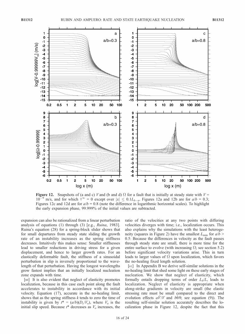
[57] A glance at Figures 9 and 10 reveals numerousinstances of expansion and contraction of the nucleationzone. Some, such as the initial expansions out to L1, can beunderstood in terms of the fracture energy balance ofsection 4. Others, such as the occasional localizationstoward Ln at large slip speeds, can be rationalized as abyproduct of excursions to moderate values of W and anapproach to the no-healing fixed length solution. Similarly,the initial expansion out to L > L1 in Figure 9a is associatedwith W < 1, whereas otherwise identical simulations withinitial conditions of (for example) W = 2 over a distance L1/2 initially undergo localization. Clearly, larger values of Whelp promote localization. However, as we discuss belowand in more detail in Appendix B, this is not the full storybecause even in the no-healing limit both expansion andlocalization are possible.[58] Figure 12 shows the evolution of V and W for a fault
that is initially at steady state with V = 10�9 m/s, and forwhich _t1 = 0 except over jxj � 0.1Lb�a (solid circles inFigures 2 and 8). The upper panels show an initial expan-sion of the nucleation zone out to distances L � L1,followed by localization. For more heterogeneous initialconditions we do not observe a well-defined expansion tolarge L, presumably because the (small) elastic stressing ratedue to this phase would be overwhelmed by the stressingrate that arises from the initial heterogeneity (i.e., multiplepeaks in slip velocity). However, all our simulations under-go some localization prior to reaching a minimum nucle-ation length (indeed, this is how the Lmin Figure 2 weredefined). Localization from longer-wavelength initial per-turbations was also noted by Dieterich [1992].[59] It is useful to view the question of expansion or
contraction of the nucleation zone as a competition betweenelasticity, which acts to smooth lateral variations in velocityand thus enlarge the nucleation zone, and slip weakening,which promotes localization. That the initial expansion inFigure 12 is due to elasticity is self-evident: Given that thenonzero remote stressing rate is restricted to a regionsmaller than Ln, only the stress increase for x ^ L due toslip over x ] L can cause L to increase. This initial
B11312 RUBIN AND AMPUERO: RATE AND STATE EARTHQUAKE NUCLEATION
15 of 24
B11312
expansion can also be rationalized from a linear perturbationanalysis of equations (1) through (3) [e.g., Ruina, 1983].Ruina’s equation (28) for a spring-block slider shows thatfor small departures from steady state sliding the growthrate of an instability increases as the spring stiffnessdecreases. Intuitively this makes sense: Smaller stiffnesseslead to smaller reductions in driving stress for a givendisplacement, and hence to larger growth rates. For anelastically deformable fault, the stiffness of a sinusoidalperturbation in slip is inversely proportional to the wave-length of that perturbation. Having the longest wavelengthsgrow fastest implies that an initially localized nucleationzone expands with time.[60] It is also evident that neglect of elasticity promotes
localization, because in this case each point along the faultaccelerates to instability in accordance with its initialvelocity. Equation (17), accurate in the no-healing limit,shows that as the spring stiffness k tends to zero the time ofinstability is given by t* = (a/b)(Dc/Vo), where Vo is theinitial slip speed. Because t* decreases as Vo increases, the
ratio of the velocities at any two points with differingvelocities diverges with time; i.e., localization occurs. Thisalso explains why the simulations with the least heteroge-neity (squares in Figure 2) have the smallest Lmin for a/b >0.5: Because the differences in velocity as the fault passesthrough steady state are small, there is more time for theentire surface to evolve (with increasing W; see section 5.2)before significant velocity variations arise. This in turnleads to larger values of W upon localization, which favorsthe no-healing fixed length solution.[61] In Appendix B we derive self-similar solutions in the
no-healing limit that shed some light on these early stages ofnucleation. We show that neglect of elasticity, whichformally entails dropping terms of order Lb/L, leads tolocalization. Neglect of elasticity is appropriate whenalong-strike gradients in velocity are small (the elasticstressing rate must be small compared to the direct andevolution effects a _V /V and b_q/q; see equation (9)). Theresulting self-similar solution accurately describes the lo-calization phase in Figure 12, despite the fact that this
Figure 12. Snapshots of (a and c) V and (b and d) W for a fault that is initially at steady state with V =10�9 m/s, and for which _t1 = 0 except over jxj � 0.1Lb�a. Figures 12a and 12b are for a/b = 0.3;Figures 12c and 12d are for a/b = 0.8 (note the difference in logarithmic horizontal scales). To highlightthe early expansion phase, 99.999% of the initial values are subtracted.
B11312 RUBIN AND AMPUERO: RATE AND STATE EARTHQUAKE NUCLEATION
16 of 24
B11312
simulation retains elasticity and the full evolution equation_q = 1 � W (Figure B1). However, a linear perturbationanalysis that retains elasticity leads to expansion of thenucleation zone for arbitrary Lb/L, as suggested by theresults of Ruina [1983]. By comparing the neglectednonlinear terms in the expanding solution to the neglectedelastic term in the localizing solution, we show that thetransition between the two is expected when Lvo � Lb,where vo is the magnitude of the velocity perturbationnormalized by the background velocity. Physically thismakes some sense: Increasing L for the same vo diminishesthe tendency for expansion by decreasing the strength ofelastic interactions, while increasing vo at the same L(stiffness) promotes localization by increasing (in a super-linear fashion) the rate at which the perturbation velocitydiverges from the background velocity.
5.2. Early Evolution of 6
[62] When elasticity can be neglected (or, more precisely,when _t1 + _tel � a _V /V), the evolution of W can bedetermined analytically. Equation (9) becomes (independentof the evolution law)
a_V
V¼ �b
_qq: ð50Þ
Because ( _Vq )/(Vq) = _V /V + _q/q, W = Vq/Dc changes least thecloser _V /V and _q/q approach each other in magnitude, or,from (50), the closer a is to b. Formally, integrating (50)yields
W tð ÞW 0ð Þ ¼
V tð ÞV 0ð Þ
� � 1�abð Þ: ð51Þ
This implies, for example, that to increase W from steadystate to 10 requires only a 2 order-of-magnitude increase inV for a/b = 0.5, but a 10 order-of-magnitude increase fora/b = 0.9. The upper dashed lines in Figure 3 shows theslope of (1 � a/b) predicted by (51); they approximate quitewell the increase of W leading to localization for both thelocalized load on an otherwise homogeneous surface (solidcircles) and the small-heterogeneity simulation (opensquares). At least in the latter case this is not surprising;reducing velocity variations along the fault minimizes theelastic stressing rate. Further reductions in initial hetero-geneity could presumably lead to values of L0.1 approachingLn for arbitrary a/b.[63] As localization proceeds, the assumption L � Lb is
progressively violated and elasticity again becomes impor-tant; eventually this precipitates the transition from locali-zation to localized acceleration in Figure 12. For a constantstiffness spring-block slider in the no-healing limit, theevolution of W can again be determined analytically. Thecondition for W to increase with V is C1 > 1, with C1 givenby (17). Approximating the stiffness by m0/2Ln and using(21), this condition becomes
L
Ln^
b
b� a: ð52Þ
This implies, for example, that the transition fromincreasing to decreasing W occurs at L � 2Ln for a/b =
0.5, but at L � 10Ln for a/b = 0.9. Indeed, for all thesimulations in Figures 3 and 9 the peak W is reached while Ldecreases, consistent with the idea that increasing thestiffness (decreasing C1) increases the magnitude of _q/qrelative to _V /V (equation (23)). Also, although (52)sometimes overestimates and sometimes underestimatesthe value of L/Ln at the peak W, we find in our simulationsthat for a/b from 0.5 to 0.9 it is almost always accurate towithin a factor of 2 and usually accurate to within severaltens of percent. Taken together, then, equations (51) and(52) provide some rationalization for the numericalresult that the peak value of W reached early in thenucleation process decreases with increasing a/b (e.g.,Figures 1 and 3).
6. Summary and Conclusions
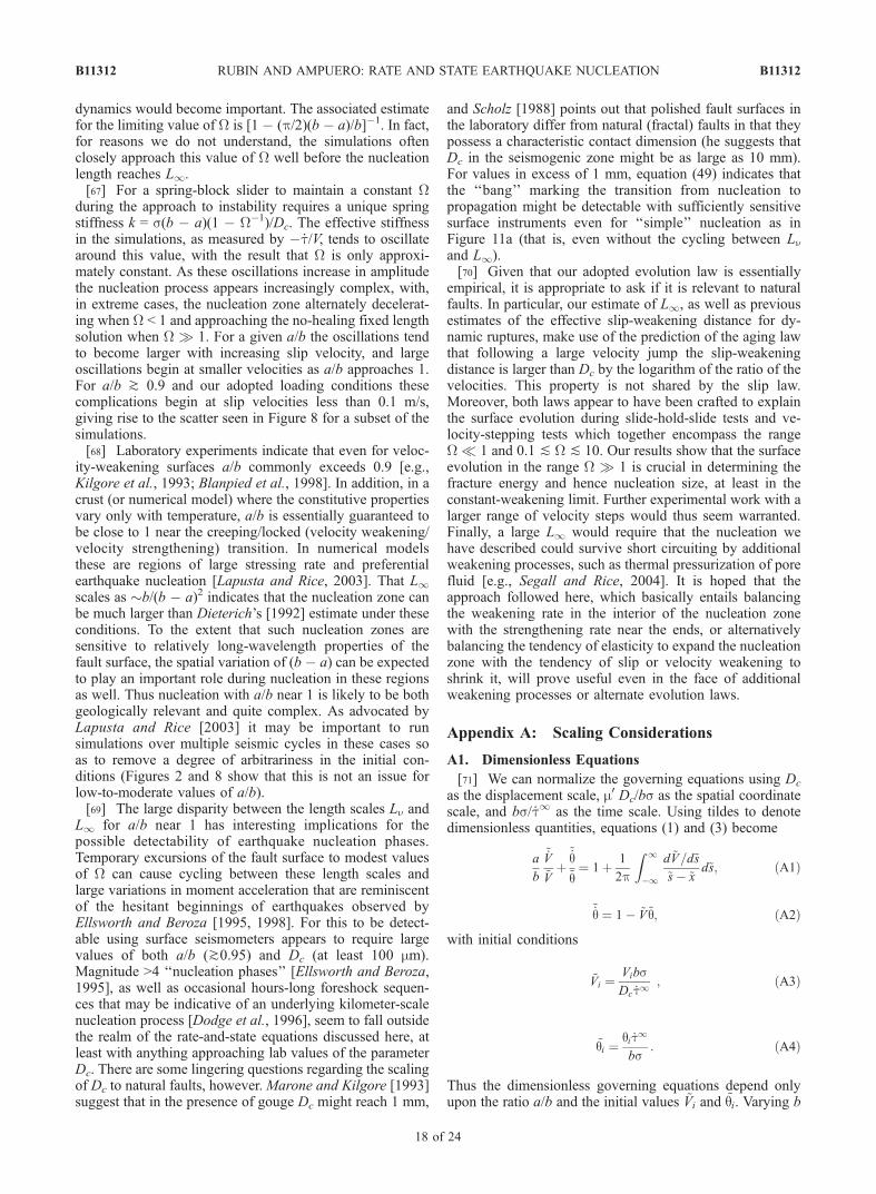
[64] We have obtained analytic estimates of the size of thenucleation zone on faults obeying Dieterich’s ‘‘aging’’version of the rate-and-state friction laws. The more robustof these estimates, applicable in the no-healing limit (W �Vq/Dc � 1), is that the nucleation zone spontaneouslyevolves toward a separable solution for accelerating slipon a crack of fixed half length Ln = 1.3774Lb, where Lb �m0Dc/bs. This is the separable solution for which K = 0, as isrequired for the crack tips to remain stationary on an infinitefault without large stress barriers. For a/b less than thecritical value of �0.3781, W increases everywhere and thefixed length solution is followed until elastodynamicsbecomes important. For a/b > 0.3781, W at the center ofthe nucleation zone decreases as instability is approachedand eventually the no-healing limit becomes inapplicable.The decrease in W is slow for a/b only slightly larger thancritical, so for even modest values of W the nucleation zonecan reach seismic velocities before departing significantlyfrom the fixed length solution. Large initial values of W arethe reason many of the examples shown by Dieterich [1992]follow this solution even for moderately large a/b.[65] Although in the no-healing limit the numerical sim-
ulations tend to the fixed length solution for which K = 0,this is not the smallest patch capable of reaching instability.Separable solutions for shorter patches have K > 0, and sowould not arise spontaneously unless the ends of thenucleation zone were somehow pinned. The minimumviable nucleation length decreases with decreasing a/b andfor a = 0 is identical to the universal nucleation length forslip-weakening faults derived by Uenishi and Rice [2003].Although for a = 0 our governing equations are identical toslip-weakening friction only in the no-healing limit, inpractice all our simulations with small a/b evolve to thislimit.[66] For a/b > 0.3781, W in the interior of the nucleation
zone decreases to a quasi-constant value W modestly inexcess of 1, and the nucleation zone takes on the appearanceof an expanding slip-weakening crack. By balancing thestress drop in the interior (constant W) with the effectiveslip-weakening properties at the crack tip (W � 1), we findthat the size of the nucleation zone approaches L1 = p�1[b/(b � a)]2 Lb in the limit that V is many orders of magnitudelarger than background. This value is approached reason-ably closely in most of our simulations by the time the slipvelocity reaches �0.1 m/s, which is roughly when elasto-
B11312 RUBIN AND AMPUERO: RATE AND STATE EARTHQUAKE NUCLEATION
17 of 24
B11312
dynamics would become important. The associated estimatefor the limiting value of W is [1 � (p/2)(b � a)/b]�1. In fact,for reasons we do not understand, the simulations oftenclosely approach this value of W well before the nucleationlength reaches L1.[67] For a spring-block slider to maintain a constant W
during the approach to instability requires a unique springstiffness k = s(b � a)(1 � W�1)/Dc. The effective stiffnessin the simulations, as measured by � _t/V, tends to oscillatearound this value, with the result that W is only approxi-mately constant. As these oscillations increase in amplitudethe nucleation process appears increasingly complex, with,in extreme cases, the nucleation zone alternately decelerat-ing when W < 1 and approaching the no-healing fixed lengthsolution when W � 1. For a given a/b the oscillations tendto become larger with increasing slip velocity, and largeoscillations begin at smaller velocities as a/b approaches 1.For a/b ^ 0.9 and our adopted loading conditions thesecomplications begin at slip velocities less than 0.1 m/s,giving rise to the scatter seen in Figure 8 for a subset of thesimulations.[68] Laboratory experiments indicate that even for veloc-
ity-weakening surfaces a/b commonly exceeds 0.9 [e.g.,Kilgore et al., 1993; Blanpied et al., 1998]. In addition, in acrust (or numerical model) where the constitutive propertiesvary only with temperature, a/b is essentially guaranteed tobe close to 1 near the creeping/locked (velocity weakening/velocity strengthening) transition. In numerical modelsthese are regions of large stressing rate and preferentialearthquake nucleation [Lapusta and Rice, 2003]. That L1scales as �b/(b � a)2 indicates that the nucleation zone canbe much larger than Dieterich’s [1992] estimate under theseconditions. To the extent that such nucleation zones aresensitive to relatively long-wavelength properties of thefault surface, the spatial variation of (b � a) can be expectedto play an important role during nucleation in these regionsas well. Thus nucleation with a/b near 1 is likely to be bothgeologically relevant and quite complex. As advocated byLapusta and Rice [2003] it may be important to runsimulations over multiple seismic cycles in these cases soas to remove a degree of arbitrariness in the initial con-ditions (Figures 2 and 8 show that this is not an issue forlow-to-moderate values of a/b).[69] The large disparity between the length scales Ln and
L1 for a/b near 1 has interesting implications for thepossible detectability of earthquake nucleation phases.Temporary excursions of the fault surface to modest valuesof W can cause cycling between these length scales andlarge variations in moment acceleration that are reminiscentof the hesitant beginnings of earthquakes observed byEllsworth and Beroza [1995, 1998]. For this to be detect-able using surface seismometers appears to require largevalues of both a/b (^0.95) and Dc (at least 100 mm).Magnitude >4 ‘‘nucleation phases’’ [Ellsworth and Beroza,1995], as well as occasional hours-long foreshock sequen-ces that may be indicative of an underlying kilometer-scalenucleation process [Dodge et al., 1996], seem to fall outsidethe realm of the rate-and-state equations discussed here, atleast with anything approaching lab values of the parameterDc. There are some lingering questions regarding the scalingof Dc to natural faults, however.Marone and Kilgore [1993]suggest that in the presence of gouge Dc might reach 1 mm,
and Scholz [1988] points out that polished fault surfaces inthe laboratory differ from natural (fractal) faults in that theypossess a characteristic contact dimension (he suggests thatDc in the seismogenic zone might be as large as 10 mm).For values in excess of 1 mm, equation (49) indicates thatthe ‘‘bang’’ marking the transition from nucleation topropagation might be detectable with sufficiently sensitivesurface instruments even for ‘‘simple’’ nucleation as inFigure 11a (that is, even without the cycling between Lnand L1).[70] Given that our adopted evolution law is essentially
empirical, it is appropriate to ask if it is relevant to naturalfaults. In particular, our estimate of L1, as well as previousestimates of the effective slip-weakening distance for dy-namic ruptures, make use of the prediction of the aging lawthat following a large velocity jump the slip-weakeningdistance is larger than Dc by the logarithm of the ratio of thevelocities. This property is not shared by the slip law.Moreover, both laws appear to have been crafted to explainthe surface evolution during slide-hold-slide tests and ve-locity-stepping tests which together encompass the rangeW � 1 and 0.1 ] W ] 10. Our results show that the surfaceevolution in the range W � 1 is crucial in determining thefracture energy and hence nucleation size, at least in theconstant-weakening limit. Further experimental work with alarger range of velocity steps would thus seem warranted.Finally, a large L1 would require that the nucleation wehave described could survive short circuiting by additionalweakening processes, such as thermal pressurization of porefluid [e.g., Segall and Rice, 2004]. It is hoped that theapproach followed here, which basically entails balancingthe weakening rate in the interior of the nucleation zonewith the strengthening rate near the ends, or alternativelybalancing the tendency of elasticity to expand the nucleationzone with the tendency of slip or velocity weakening toshrink it, will prove useful even in the face of additionalweakening processes or alternate evolution laws.
Appendix A: Scaling Considerations
A1. Dimensionless Equations
[71] We can normalize the governing equations using Dc
as the displacement scale, m0 Dc/bs as the spatial coordinatescale, and bs/ _t1 as the time scale. Using tildes to denotedimensionless quantities, equations (1) and (3) become
a
b
~_V~Vþ~_q~q¼ 1þ 1
2p
Z 1
�1
d ~V=d~s
~s� ~xd~s; ðA1Þ
~_q ¼ 1� ~V~q; ðA2Þ
with initial conditions
~Vi ¼VibsDc _t1
; ðA3Þ
~qi ¼qi _t1
bs: ðA4Þ
Thus the dimensionless governing equations depend onlyupon the ratio a/b and the initial values ~Vi and ~qi. Varying b
B11312 RUBIN AND AMPUERO: RATE AND STATE EARTHQUAKE NUCLEATION
18 of 24
B11312
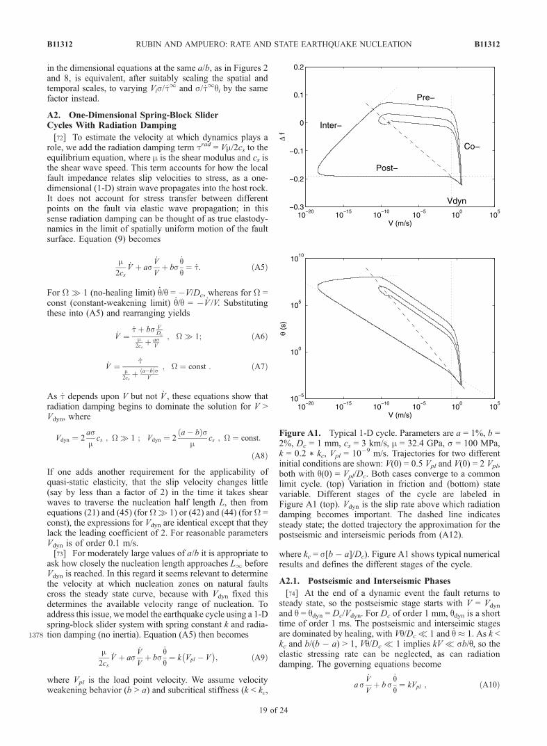
in the dimensional equations at the same a/b, as in Figures 2and 8, is equivalent, after suitably scaling the spatial andtemporal scales, to varying Vis/ _t
1 and s/ _t1qi by the samefactor instead.
A2. One-Dimensional Spring-Block SliderCycles With Radiation Damping
[72] To estimate the velocity at which dynamics plays arole, we add the radiation damping term trad = Vm/2cs to theequilibrium equation, where m is the shear modulus and cs isthe shear wave speed. This term accounts for how the localfault impedance relates slip velocities to stress, as a one-dimensional (1-D) strain wave propagates into the host rock.It does not account for stress transfer between differentpoints on the fault via elastic wave propagation; in thissense radiation damping can be thought of as true elastody-namics in the limit of spatially uniform motion of the faultsurface. Equation (9) becomes
m2cs
_V þ as_V
Vþ bs
_qq¼ _t: ðA5Þ
For W � 1 (no-healing limit) _q/q = �V/Dc, whereas for W =const (constant-weakening limit) _q/q = � _V /V. Substitutingthese into (A5) and rearranging yields
_V ¼_tþ bs V
Dc
m2cs
þ asV
; W � 1; ðA6Þ
_V ¼ _tm2cs
þ a�bð ÞsV
; W ¼ const : ðA7Þ
As _t depends upon V but not _V , these equations show thatradiation damping begins to dominate the solution for V >Vdyn, where
Vdyn ¼ 2asmcs ; W � 1 ; Vdyn ¼ 2
a� bð Þsm
cs ; W ¼ const:
ðA8Þ
If one adds another requirement for the applicability ofquasi-static elasticity, that the slip velocity changes little(say by less than a factor of 2) in the time it takes shearwaves to traverse the nucleation half length L, then fromequations (21) and (45) (for W� 1) or (42) and (44) (for W =const), the expressions for Vdyn are identical except that theylack the leading coefficient of 2. For reasonable parametersVdyn is of order 0.1 m/s.[73] For moderately large values of a/b it is appropriate to
ask how closely the nucleation length approaches L1 beforeVdyn is reached. In this regard it seems relevant to determinethe velocity at which nucleation zones on natural faultscross the steady state curve, because with Vdyn fixed thisdetermines the available velocity range of nucleation. Toaddress this issue, we model the earthquake cycle using a 1-Dspring-block slider system with spring constant k and radia-
1378 tion damping (no inertia). Equation (A5) then becomes
m2cs
_V þ as_V
Vþ bs
_qq¼ k Vpl � V� �
; ðA9Þ
where Vpl is the load point velocity. We assume velocityweakening behavior (b > a) and subcritical stiffness (k < kc,
where kc = s[b � a]/Dc). Figure A1 shows typical numericalresults and defines the different stages of the cycle.
A2.1. Postseismic and Interseismic Phases
[74] At the end of a dynamic event the fault returns tosteady state, so the postseismic stage starts with V = Vdyn
and q = qdyn = Dc/Vdyn. For Dc of order 1 mm, qdyn is a shorttime of order 1 ms. The postseismic and interseimic stagesare dominated by healing, with Vq/Dc � 1 and _q � 1. As k <kc and b/(b � a) > 1, Vq/Dc � 1 implies kV � sb/q, so theelastic stressing rate can be neglected, as can radiationdamping. The governing equations become
as_V
Vþ b s
_qq¼ kVpl ; ðA10Þ
Figure A1. Typical 1-D cycle. Parameters are a = 1%, b =2%, Dc = 1 mm, cs = 3 km/s, m = 32.4 GPa, s = 100 MPa,k = 0.2 * kc, Vpl = 10�9 m/s. Trajectories for two differentinitial conditions are shown: V(0) = 0.5 Vpl and V(0) = 2 Vpl,both with q(0) = Vpl/Dc. Both cases converge to a commonlimit cycle. (top) Variation in friction and (bottom) statevariable. Different stages of the cycle are labeled inFigure A1 (top). Vdyn is the slip rate above which radiationdamping becomes important. The dashed line indicatessteady state; the dotted trajectory the approximation for thepostseismic and interseismic periods from (A12).
B11312 RUBIN AND AMPUERO: RATE AND STATE EARTHQUAKE NUCLEATION
19 of 24
B11312
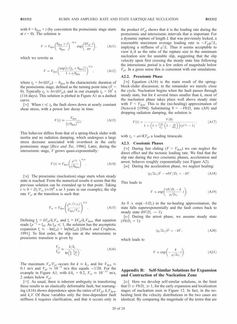
with q = qdyn + t (by convention the postseismic stage startsat t = 0). The solution is
V ¼ Vdyn
qdyn þ t
qdyn
� ��b=a
expkVpl t
as
� �; ðA11Þ
which we rewrite as
V ¼ Vdyn
exp t= tp þ qdyn� � �
1þ t=qdyn
� �b=a
; ðA12Þ
where tp = bs/(kVpl) � qdyn is the characteristic duration ofthe postseismic stage, defined as the turning point time ( _V =0). Typically tp � bs/(kVpl), and in our example tp = 107 s(116 days). This solution is plotted in Figure A1 as a dashedcurve.[75] When t � tp the fault slows down at nearly constant
shear stress, with a power law decay in time:
V tð Þ � Vdyn
t=qdyn� �b=a : ðA13Þ
This behavior differs from that of a spring-block slider withinertia and no radiation damping, which undergoes a largestress decrease associated with overshoot in the earlypostseismic stage [Rice and Tse, 1986]. Later, during theinterseismic stage, V grows quasi-exponentially:
V tð Þ � Vdyn
et=tp
t=qdyn
� �b=a
: ðA14Þ
[76] The preseismic (nucleation) stage starts when steadystate is reached. From the numerical results it seems that theprevious solution can be extended up to that point. Takingt � q = Dc/Vss (�108 s or 3 years in our example), the sliprate Vss at the transition is such that:
Vss ¼ Vdyn
eDc= Vsstpð ÞVdyn=Vss
!b=a
: ðA15Þ
Defining x = kVpl/kcVss and x = kVpl/kcVdyn, that equationreads xe�x = x0. As x0 � 1, the solution has the asymptoticexpansion x � �ln(x0) + ln(ln(x0)) [Hinch and Crighton,1991]. To first order, the slip rate at the interseismic topreseismic transition is given by
Vss
Vpl
� k=kc
ln kck
Vdyn
Vpl
� � : ðA16Þ
The maximum Vss/Vpl occurs for k � kc, and for Vdyn �0.1 m/s and Vpl � 10�9 m/s this equals �1/20. For theexample in Figure A1, with k/kc = 0.2, Vss � 10�11 m/s,2 orders below Vpl.[77] As usual, there is inherent ambiguity in transferring
these results to an elastically deformable fault, but rearrang-ing (A16) shows dependence upon the ratios of kVpl, kcVdyn,and kcV. Of these variables only the time-dependent faultstiffness k requires clarification, and that it occurs only in
the product kVpl shows that it is the loading rate during thepostseismic and interseismic intervals that is important. Fora dynamic rupture of length L that was previously locked, areasonable maximum average loading rate is �Vplm
0/L,implying a stiffness of m0/L. Thus it seems acceptable toview kc/k as the ratio of the rupture size to the minimumnucleation size for unstable slip, suggesting that the slipvelocity upon first crossing the steady state line followingthe interseismic period is a few orders of magnitude belowVpl. In a gross sense this is consistent with our simulations.
A2.2. Preseismic Phase
[78] Equation (A16) is the main result of the spring-block-slider discussion; in the remainder we merely closethe cycle. Nucleation begins when the fault passes throughsteady state, but for k several times smaller than kc most ofthe nucleation phase takes place well above steady statewith V < Vdyn. This is the (no-healing) approximation ofDieterich [1994]. Substituting _q = �Vq/Dc into (A9) anddropping radiation damping, the solution is
V tð Þ ¼ V 0ð Þ1þ 1þ V 0ð Þ
Vpl1� sb
kDc
� �� �et=ta � 1ð Þ
; ðA17Þ
with ta = as/KVpl a loading timescale.
A2.3. Coseismic Phases
[79] During fast sliding (V > Vdyn) we can neglect thedirect effect and the tectonic loading rate. We find that theslip rate during the two coseismic phases, acceleration andarrest, behaves roughly exponentially (see Figure A2).[80] During the acceleration phase, we neglect healing:
m=2csð Þ _V � sbV=Dc ¼ �kV : ðA18Þ
This leads to
V / expsb=Dc � k
m=2cst
� �: ðA19Þ
As q / exp(�d/Dc) in the no-healing approximation, thestate falls superexponentially and the fault comes back tosteady state (qV/Dc ! 1).[81] During the arrest phase, we assume steady state
(Vq/Dc = 1):
m=2csð Þ _V ¼ �kV ; ðA20Þ
which leads to
V / exp � k
m=2cst
� �: ðA21Þ
Appendix B: Self-Similar Solutions for Expansionand Contraction of the Nucleation Zone
[82] Here we develop self-similar solutions, in the limitthat W� Vq/Dc � 1, for the early expansion and localizationstages of nucleation seen in Figure 12. In fact, in the no-healing limit the velocity distributions in the two cases areidentical. By comparing the magnitude of the terms that are
B11312 RUBIN AND AMPUERO: RATE AND STATE EARTHQUAKE NUCLEATION
20 of 24
B11312
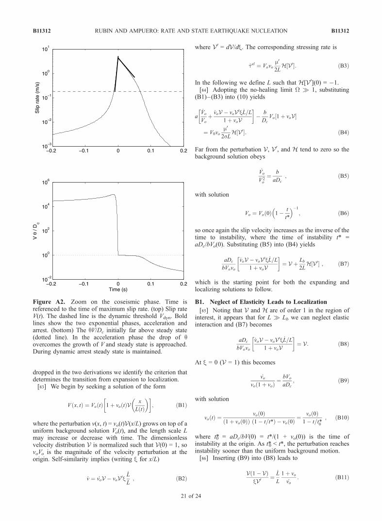
dropped in the two derivations we identify the criterion thatdetermines the transition from expansion to localization.[83] We begin by seeking a solution of the form
V x; tð Þ ¼ Vo tð Þ 1þ vo tð ÞV x
L tð Þ
� �� �; ðB1Þ
where the perturbation v(x, t) = vo(t)V(x/L) grows on top of auniform background solution Vo(t), and the length scale Lmay increase or decrease with time. The dimensionlessvelocity distribution V is normalized such that V(0) = 1, sovoVo is the magnitude of the velocity perturbation at theorigin. Self-similarity implies (writing x for x/L)
_v ¼ _voV � voV0x_L
L; ðB2Þ
where V0 = dV/dx. The corresponding stressing rate is
_tel ¼ Vovom0
2LH V0½ : ðB3Þ
In the following we define L such that H[V0](0) = �1.[84] Adopting the no-healing limit W � 1, substituting
(B1)–(B3) into (10) yields
a_Vo
Vo
þ _voV � voV0x _L=L1þ voV
� �� b
Dc
Vo 1þ voV½
¼ V0vom0
2sLH V0½ : ðB4Þ
Far from the perturbation V, V0, and H tend to zero so thebackground solution obeys
_Vo
V 2o
¼ b
aDc
; ðB5Þ
with solution
Vo ¼ Vo 0ð Þ 1� t
t*
� ��1
; ðB6Þ
so once again the slip velocity increases as the inverse of thetime to instability, where the time of instability t* =aDc/bVo(0). Substituting (B5) into (B4) yields
aDc
bVovo
_voV � voV0x _L=L1þ voV
� �¼ V þ Lb
2LH V0½ ; ðB7Þ
which is the starting point for both the expanding andlocalizing solutions to follow.
B1. Neglect of Elasticity Leads to Localization
[85] Noting that V and H are of order 1 in the region ofinterest, it appears that for L � Lb we can neglect elasticinteraction and (B7) becomes
aDc
bVovo
_voV � voV0x _L=L1þ voV
� �¼ V: ðB8Þ
At x = 0 (V = 1) this becomes
_vovo 1þ voð Þ ¼
bVo
aDc
; ðB9Þ
with solution
vo tð Þ ¼ vo 0ð Þ1þ vo 0ð Þð Þ 1� t=t*ð Þ � vo 0ð Þ ¼
vo 0ð Þ1� t=t
0*
; ðB10Þ
where t*0 = aDc/bV(0) = t*/(1 + vo(0)) is the time ofinstability at the origin. As t*0 < t*, the perturbation reachesinstability sooner than the uniform background motion.[86] Inserting (B9) into (B8) leads to
V 1� Vð ÞxV0 ¼
_L
L
1þ vo
_vo: ðB11Þ
Figure A2. Zoom on the coseismic phase. Time isreferenced to the time of maximum slip rate. (top) Slip rateV(t). The dashed line is the dynamic threshold Vdyn. Boldlines show the two exponential phases, acceleration andarrest. (bottom) The qV/Dc initially far above steady state(dotted line). In the acceleration phase the drop of qovercomes the growth of V and steady state is approached.During dynamic arrest steady state is maintained.
B11312 RUBIN AND AMPUERO: RATE AND STATE EARTHQUAKE NUCLEATION
21 of 24
B11312
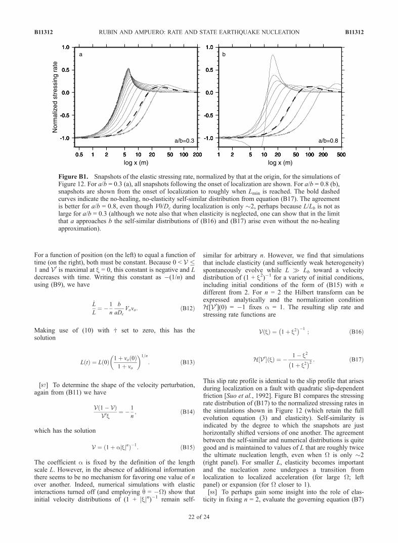
For a function of position (on the left) to equal a function oftime (on the right), both must be constant. Because 0 < V �1 and V0 is maximal at x = 0, this constant is negative and Ldecreases with time. Writing this constant as �(1/n) andusing (B9), we have
_L
L¼ � 1
n
b
aDc
Vovo: ðB12Þ
Making use of (10) with _t set to zero, this has thesolution
L tð Þ ¼ L 0ð Þ 1þ vo 0ð Þ1þ vo
� �1=n
: ðB13Þ
[87] To determine the shape of the velocity perturbation,again from (B11) we have
V 1� Vð ÞV0x
¼ � 1
n; ðB14Þ
which has the solution
V ¼ 1þ ajxjnð Þ�1: ðB15Þ
The coefficient a is fixed by the definition of the lengthscale L. However, in the absence of additional informationthere seems to be no mechanism for favoring one value of nover another. Indeed, numerical simulations with elasticinteractions turned off (and employing _q = �W) show thatinitial velocity distributions of (1 + jxjn)�1 remain self-
similar for arbitrary n. However, we find that simulationsthat include elasticity (and sufficiently weak heterogeneity)spontaneously evolve while L � Lb toward a velocitydistribution of (1 + x2)�1 for a variety of initial conditions,including initial conditions of the form of (B15) with ndifferent from 2. For n = 2 the Hilbert transform can beexpressed analytically and the normalization conditionH[V0](0) = �1 fixes a = 1. The resulting slip rate andstressing rate functions are
V xð Þ ¼ 1þ x2� ��1
; ðB16Þ
H V0½ xð Þ ¼ � 1� x2
1þ x2� �2 : ðB17Þ
This slip rate profile is identical to the slip profile that arisesduring localization on a fault with quadratic slip-dependentfriction [Suo et al., 1992]. Figure B1 compares the stressingrate distribution of (B17) to the normalized stressing rates inthe simulations shown in Figure 12 (which retain the fullevolution equation (3) and elasticity). Self-similarity isindicated by the degree to which the snapshots are justhorizontally shifted versions of one another. The agreementbetween the self-similar and numerical distributions is quitegood and is maintained to values of L that are roughly twicethe ultimate nucleation length, even when W is only �2(right panel). For smaller L, elasticity becomes importantand the nucleation zone undergoes a transition fromlocalization to localized acceleration (for large W; leftpanel) or expansion (for W closer to 1).[88] To perhaps gain some insight into the role of elas-
ticity in fixing n = 2, evaluate the governing equation (B7)
Figure B1. Snapshots of the elastic stressing rate, normalized by that at the origin, for the simulations ofFigure 12. For a/b = 0.3 (a), all snapshots following the onset of localization are shown. For a/b = 0.8 (b),snapshots are shown from the onset of localization to roughly when Lmin is reached. The bold dashedcurves indicate the no-healing, no-elasticity self-similar distribution from equation (B17). The agreementis better for a/b = 0.8, even though Vq/Dc during localization is only �2, perhaps because L/Lb is not aslarge for a/b = 0.3 (although we note also that when elasticity is neglected, one can show that in the limitthat a approaches b the self-similar distributions of (B16) and (B17) arise even without the no-healingapproximation).
B11312 RUBIN AND AMPUERO: RATE AND STATE EARTHQUAKE NUCLEATION
22 of 24
B11312
at x = 0 and substitute that result and (B12) back into (B7)to obtain
Lb
2L tð Þ1þ voð ÞV1þ voV
þHþ voV0
1þ voVxn
� �
¼ 1þ voð ÞV1þ voV
� V þ voV0
1þ voVxn
� �: ðB18Þ
Because the left side of (B18) is the product of a(nonconstant) function of time alone and a function ofposition alone (in brackets), and the right is a function ofposition alone, equality requires that both sides equal zero.The bracketed functions cannot both be zero because thiswould require that the normalized stressing rate exactlymirror the normalized velocity (that is, H = �V). In thelimit of large L the left side approaches zero and (B14) isrecovered. Nonetheless, the left side of (B18) is nonzero forfinite L. We find numerically that the favored solution (n =2) is that which minimizes the maximum value of thebracketed expression on the left; that is, it minimizes themaximum difference between H and �V. For n = 2 thismaximum occurs at x = 1 and equals 1/2.
B2. Linearization With Elasticity Leads to Expansion
[89] We next obtain a self-similar solution that retainselasticity by evaluating (B7) in the limit of small velocityperturbations vo. This amounts to dropping the voV term inthe denominator of the bracketed expression on the left,which leads to
aDc
b_voV � voV0x
_L
L
� �� VovoV ¼ V0vo
Lb
2LH V0½ : ðB19Þ
Maintaining the normalizations V(0) = 1 and H(V0)(0) =�1, evaluating (B19) at x = 0 yields
aDc
b_vo � Vovo ¼ �V0vo
Lb
2L: ðB20Þ
Substituting this back into (B19),
�V �H V0ð ÞV0x
¼ 2asm0
_L
Vo
: ðB21Þ
[90] An analysis using a forward and inverse Fouriertransform (not shown here) shows that the self-similarvelocity distribution satisfying (B21) is identical to thatsatisfying (B11) of section B1. So, substituting (B16) for Vand (B17) for H into (B21) we obtain
V 1� Vð ÞV0x
¼ � asm0
_L
Vo
¼ � 1
2; ðB22Þ
which leads to
_L ¼ m0
2asVo ¼
m0
2asVo 0ð Þ 1� t=t*ð Þ�1; ðB23Þ
where t* = aDc/bVo(0) is the time of instability for thebackground solution. Integration yields
L tð Þ ¼ � Lb
2ln 1� t=t*ð Þ þ L 0ð Þ : ðB24Þ
Note that in this case L increases with time, albeit slowlycompared to the decrease during localization (in the limitthat t � t* and vo � 1, jdL/d(lnVo)j during localizationexceeds that during expansion by roughly the ratio L/Lb).[91] To determine vo, evaluating (B19) at x = 1 (V = 1/2;
H(V0) = 0; V0 = �1/2) yields
_vovo
¼ bVo
aDc
�_L
L; ðB25Þ
which has the solution
vo tð Þ ¼ L�1vo 0ð Þ 1� t=t*ð Þ�1: ðB26Þ
B3. Expansion or Localization?
[92] The above results present something of a paradox.As (B22) is identical to (B14) (since in the latter n = 2), thevelocity distributions V for the expanding and localizingsolutions are identical. Given this velocity distribution as aninitial condition, then, which solution does a numericalsimulation follow? To address this question, we return tothe governing equation (B7) and compare the magnitudes ofterms that were subsequently neglected in the two deriva-tions. For vo � 1, (1 + voV)�1 � (1 � voV) and to first orderthe terms neglected in the linearized (expanding) version are
aDc
bVovo� _voV þ voVV0x _L=L� �
: ðB27Þ
The neglected elastic term in the localizing solution is
m0Dc
2bsLH V0ð Þ: ðB28Þ
Because the x-dependent variables are of order 1, theseexpressions are of comparable magnitude when
_vovo
þ_L
L� b
aDc
Vo
vo
Lb
2L: ðB29Þ
Using the (linearized) result (B25) to eliminate _vo/vo, thisbecomes
L � Lb=2vo: ðB30Þ
[93] If instead of (B25) one uses the no-elasticity results(B12) and (B9) evaluated at t = 0, the result is the same towithin a factor of 1 to 2 (depending upon the magnitude ofvo[0]). The implication is that for L ^ Lb/vo one expectselasticity to be truly negligible and localization to dominateimmediately, while for L ] Lb/vo elasticity is nonnegligible,even for L � Lb, and expansion should dominate initially.This is confirmed by numerical simulations (that employ _q =�W) in that simulations with L(0)/Lb = 10 initially undergoexpansion for vo = 0.01 but localization for vo = 1. Becauseboth L and vo increase with time for simulations that initiallyexpand, eventually Lvo exceeds Lb and localization is guar-anteed. During localizationLvo increases (as vo/[1 + vo]
1/2; seeequation (B13)), so localization continues until L � Lbbecomes invalid and elasticity again becomes important.
B11312 RUBIN AND AMPUERO: RATE AND STATE EARTHQUAKE NUCLEATION
23 of 24
B11312
[94] Because the simulations in Figure 12 employ the fullevolution equation _q = 1 � W, the velocity of the expansion( _L) is more rapid than predicted by (B23) and the value ofLvo at the transition to localization may, for large a/b, beconsiderably larger than Lb. We can rationalize this bynoting that the initial expansion, and for large a/b eventhe transition to localization, occur while W is only slightlylarger than 1. This reduces the effective slip-weakening ratewithout changing the strength of elastic interactions, so itdiminishes the tendency for localization relative to that forexpansion.
[95] Acknowledgments. We thank Alain Cochard for providing uswith notes on the numerical solution of the governing equations and hiselastodynamic code used to check our radiation damping solutions, JimRice for reminding us what self-similarity really means, and Nadia Lapustafor advice on notation. This paper benefited from comments by two quasi-anonymous reviewers and the associate editor. Supported by NSF awardEAR-0126184.
ReferencesAbercrombie, R. E. (1996), The magnitude-frequency distribution of earth-quakes recorded with deep seismometers at cajon pass, southern califor-nia, Tectonophsysics, 261, 1–7.
Ampuero, J.-P. (2002), Etude physique et numerique de la nucleation desseismes, Ph.D. thesis, Univ. Paris 7, Denis Diderot, Paris.
Beeler, N. M., T. E. Tullis, and J. D. Weeks (1994), The roles of time anddisplacement in the evolution effect in rock friction, Geophys. Res. Lett.,21, 1987–1990.
Bizzarri, A., and M. Cocco (2003), Slip-weakening behavior during thepropagation of dynamic ruptures obeying rate- and state-dependent fric-tion laws, J. Geophys. Res., 108(B8), 2373, doi:10.1029/2002JB002198.
Blanpied, M. L., C. J. Marone, D. A. Lockner, J. D. Byerlee, and D. P. King(1998), Quantitative measure of the variation in fault rheology due tofluid-rock interactions, J. Geophys. Res., 103, 9691–9712.
Chen, Y. T., and L. Knopoff (1986), Static shear crack with a zone of slip-weakening, Geophys. J. R. Astron. Soc., 87, 1005–1024.
Dascalu, C., I. R. Ionescu, and M. Campillo (2000), Fault finiteness andinitiation of dynamic shear instability, Earth Planet. Sci. Lett., 177,163–176.
Dieterich, J. H. (1979), Modeling of rock friction: 1. Experimental resultsand constitutive equations, J. Geophys. Res., 84, 2161–2168.
Dieterich, J. H. (1992), Earthquake nucleation on faults with rate- and state-dependent friction, Tectonophysics, 211, 115–134.
Dieterich, J. H. (1994), A constitutive law for rate of earthquake productionand its application to earthquake clustering, J. Geophys. Res., 99, 2601–2618.
Dieterich, J. H., and B. D. Kilgore (1994), Direct observation of frictionalcontacts: New insights for state-dependent properties, Pure Appl. Geo-phys., 143, 283–302.
Dieterich, J. H., and B. D. Kilgore (1996), Implications of fault constitutiveproperties for earthquake prediction, Proc. Natl. Acad. Sci. U.S.A., 93,3787–3794.
Dodge, D. A., G. C. Beroza, and W. L. Ellsworth (1996), Detailedobservations of California foreshock sequences: Implications forthe earthquake initiation process, J. Geophys. Res., 101, 22,371 –22,392.
Ellsworth, E. L., and G. C. Beroza (1995), Seismic evidence for an earth-quake nucleation phase, Science, 268, 851–855.
Ellsworth, E. L., and G. C. Beroza (1998), Observation of the seismicnucleation phase in the Ridgecrest, California, earthquake sequence, Geo-phys. Res. Lett., 25, 401–404.
Hinch, E. J., and D. G. Crighton (Eds.) (1991), Perturbation Methods,Cambridge Univ. Press, New York.
Kilgore, B. D., M. L. Blanpied, and J. H. Dieterich (1993), Velocity de-pendent friction of granite over a wide range of conditions, Geophys. Res.Lett., 20, 903–906.
Lapusta, N., and J. R. Rice (2002), Nucleation of rate and state frictionalinstability under non-uniform loading, Eos Trans. AGU, 83(47), FallMeet. Suppl., Abstract S61E-05.
Lapusta, N., and J. R. Rice (2003), Nucleation and early seismic propaga-tion of small and large events in a crustal earthquake model, J. Geophys.Res., 108(B4), 2205, doi:10.1029/2001JB000793.
Lawn, B. (1993), Fracture of Brittle Solids, 2nd ed., Cambridge Univ.Press, New York.
Marone, C. (1998), Laboratory-derived friction laws and their application toseismic faulting, Annu. Rev. Earth Planet. Sci., 26, 643–646.
Marone, C., and B. Kilgore (1993), Scaling of the critical slip distance forseismic faulting with shear strain in fault zones, Nature, 362, 618–621.
Nakatani, M. (2001), Conceptual and physical clarification of rate and statefriction: Frictional sliding as a thermally activated rheology, J. Geophys.Res., 106, 13,347–13,380.
Press, W. H., B. P. Flannery, S. A. Teukolsky, and W. T. Vetterling (1986),Numerical Recipes: The Art of Scientific Computing, Cambridge Univ.Press, New York.
Ranjith, K., and J. R. Rice (2003), Stability of quasi-static slip in a singledegree of freedom elastic system with rate and state dependent friction,J. Mech. Phys. Solids, 47, 1207–1218.
Rice, J. R. (1993), Spatio-temporal complexity of slip on a fault, J. Geo-phys. Res., 98, 9885–9907.
Rice, J. R., and A. L. Ruina (1983), Stability of steady frictional slipping,J. Appl. Mech., 50, 343–349.
Rice, J. R., and S. T. Tse (1986), Dynamic motion of a single degree offreedom system following a rate- and state-dependent friction law,J. Geophys. Res., 91, 521–530.
Rice, J. R., N. Lapusta, and K. Ranjith (2003), Rate- and state-dependentfriction and the stability of sliding between elastically deformable solids,J. Mech. Phys. Sol., 49, 1865–1898.
Ruina, A. (1983), Slip instability and state variable friction laws, J. Geo-phys. Res., 88, 10,359–10,370.
Scholz, C. H. (1988), The critical slip distance for seismic faulting, Nature,336, 761–763.
Segall, P., and J. R. Rice (2004), Transition from frictional weakening toshear heating induced thermal pressurization, Eos Trans. AGU, 85(47),Fall Meet. Suppl., Abstract T22A-07.
Spence, D. A., and P. Sharp (1895), Self-similar solutions for elasto-hydrodynamic cavity flow, Proc. R. Soc. London, Ser. A, 400, 289–313.
Suo, Z., M. Ortiz, and A. Needleman (1992), Stability of solids with inter-faces, J. Mech. Phys. Solids, 40, 613–640.
Tullis, T. E. (1988), Rock friction constitutive behavior from laboratoryexperiments and its implications for an earthquake prediction field mon-itoring program, Pure Appl. Geophys., 126, 555–588.
Uenishi, K., and J. R. Rice (2003), Universal nucleation length for slip-weakening rupture instability under nonuniform fault loading, J. Geo-phys. Res., 108(B1), 2042, doi:10.1029/2001JB001681.
�����������������������J.-P. Ampuero, Institute of Geophysics, Seismology and Geodynamics
ETH Honggerberg (HPP), CH-8093 Zurich, Switzerland.A. M. Rubin, Department of Geosciences, Princeton University, Guyot
Hall, Princeton, NJ 08544, USA. ([email protected])
B11312 RUBIN AND AMPUERO: RATE AND STATE EARTHQUAKE NUCLEATION
24 of 24
B11312