surface and underground excavations
TRANSCRIPT
Excavation is a multi-disciplinary activity in the areas of civil, construction andmining engineering. The excavation industry is booming by the yearly creationof thousands of kilometers of tunnels, many mine openings and millions ofcubic meters of large underground excavations for transportation, mineralmining, oil and gas storage, hydroelectric power station construction, defensefacilities and for the disposal of hazardous waste.
Surface and Underground Excavations – Methods, Techniquesand Equipment provides a comprehensive text on the latest technologiesand developments in excavation for any type of surface or undergroundexcavation. In the first few chapters, unit operations are covered, includingdrilling, explosives and blasting, mucking, haulage, hoisting, supports andreinforcement. Subsequently, excavation techniques are described for variousoperations, like tunneling, raising, sinking, drifting, stoping, quarrying andsurface-mining, underground mining, pillar blasting and liquidation. In addi-tion, the design, planning and development of excavations are treated in aseparate chapter. Special attention is paid to the construction of surface andsubsurface excavations, including caverns and to new methodologies toselect stoping methods through incremental analysis. For practical illustration,one of the final chapters contains case studies dealing with heavy under-ground blasting during pillar recoveries.
This book is intended for students in earth sciences, geology and in civil, miningand construction engineering.
Surface and UndergroundExcavations
Methods, Techniques and Equipment
Ratan Raj Tatiya
Tatiya
Su
rfac
e a
nd
Un
de
rgro
un
d E
xc
avatio
ns
Methods, Techniques and E
quipment
Balkema
cover_Tatyia_final 27-06-2005 18:16 Pagina 1

Surface and Underground Excavations – Methods, Techniques and Equipment

Surface and UndergroundExcavations – Methods, Techniques andEquipment
Ratan Raj Tatiya, PhD, BEng
A.A. BALKEMA PUBLISHERS LEIDEN / LONDON / NEW YORK / PHILADELPHIA / SINGAPORE
CRC PressTaylor & Francis Group6000 Broken Sound Parkway NW, Suite 300Boca Raton, FL 33487-2742
© 2005 by Taylor & Francis Group, LLCCRC Press is an imprint of Taylor & Francis Group, an Informa business
No claim to original U.S. Government worksVersion Date: 20150129
International Standard Book Number-13: 978-1-4398-3422-0 (eBook - PDF)
This book contains information obtained from authentic and highly regarded sources. Reasonable efforts have been made to publish reliable data and information, but the author and publisher cannot assume responsibility for the validity of all materials or the consequences of their use. The authors and publishers have attempted to trace the copyright holders of all material reproduced in this publication and apologize to copyright holders if permission to publish in this form has not been obtained. If any copyright material has not been acknowledged please write and let us know so we may rectify in any future reprint.
Except as permitted under U.S. Copyright Law, no part of this book may be reprinted, reproduced, transmitted, or utilized in any form by any electronic, mechanical, or other means, now known or hereafter invented, including pho-tocopying, microfilming, and recording, or in any information storage or retrieval system, without written permis-sion from the publishers.
For permission to photocopy or use material electronically from this work, please access www.copyright.com (http://www.copyright.com/) or contact the Copyright Clearance Center, Inc. (CCC), 222 Rosewood Drive, Danvers, MA 01923, 978-750-8400. CCC is a not-for-profit organization that provides licenses and registration for a variety of users. For organizations that have been granted a photocopy license by the CCC, a separate system of payment has been arranged.
Trademark Notice: Product or corporate names may be trademarks or registered trademarks, and are used only for identification and explanation without intent to infringe.
Visit the Taylor & Francis Web site athttp://www.taylorandfrancis.com
and the CRC Press Web site athttp://www.crcpress.com

DedicationTo my wife Shashi, and children Anand, Gaurav and Sapna.

Contents
Preface XIXConversion tables XXI
CHAPTER 1 INTRODUCTION 11.1 Excavations and their classification 11.2 Surface excavations 21.3 Underground excavations 21.4 Importance of minerals and brief history to recover them 31.5 Current status of mineral industry 61.6 Excavation technologies/systems – development & growth 61.7 Unique features of mineral industry 11
1.7.1 Different Phases of mine life 131.8 Brief history civil work excavations including tunneling 131.9 Tommorow’s mine & civil excavations 15
References 17
CHAPTER 2 ROCKS AND MINERALS 192.1 Formation process and classification 19
2.1.1 Igneous rocks 192.1.2 Sedimentary rocks 212.1.3 Metamorphic rocks 22
2.2 Rock cycle & type of deposits 222.3 Texture, grain size and shape 24
2.3.1 Grain sizes and shapes 252.3.2 Durability, plasticity and swelling potential of rocks 25
2.4 The concepts of mineral resources and reserves; mineral inventory,cutoff grade, and ores 252.4.1 Some important ores – chemical & mineralogical composition 26
2.5 Geological structures 262.5.1 Geometry of a deposit 262.5.2 Deposits’ forms 262.5.3 Structural features of rock mass 26
2.6 Physical & mechanical characteristics of ores and rocks 312.6.1 Rocks as per rock mechanics 312.6.2 Rock composition 312.6.3 Rock strength 33
2.7 Some other properties/characteristics 332.7.1 Hardness of minerals 332.7.2 Rocks’ breakability 35
2.8 Related terms – rock and mineral deposits 36References 38
CHAPTER 3 PROSPECTING, EXPLORATION & SITE INVESTIGATIONS 393.1 Introduction 393.2 Prospecting and exploration 39
VIII CONTENTS
3.2.1 Finding signs of the mineral in the locality or general indications 393.2.1.1 Geological studies 403.2.1.2 Geo-chemical studies 40
3.2.2 Finding the deposit or preliminary proving 403.2.2.1 Geophysical methods/studies/surveys 413.2.2.2 Putting exploratory headings 45
3.2.3 Exploring the deposits or detailed proving – prospectingdrilling 45
3.3 Phases of prospecting and exploration program 493.4 Site investigations for civil constructions, or any
excavation project including tunnels and caverns 513.5 Rocks and ground characterization 52
3.5.1 Rock strength classification 523.5.2 Rock mass classifications 52
3.6 Rock quality designation (rqd) 533.6.1 Q (Rock mass quality) system 563.6.2 Geomechanics classification (RMR system) 563.6.3 Rock structure rating (RSR) 56REFERENCES 59
CHAPTER 4 DRILLING 614.1 Introduction – unit operations 614.2 Primary rock breaking 614.3 Drilling 624.4 Operating components of the drilling system 624.5 Mechanics of rock penetration 63
4.5.1 Top-hammer drilling 634.5.2 Down-the-hole (DTH) drilling 644.5.3 Rotary drilling 654.5.4 Augur drill 654.5.5 Rotary abrasive drilling (This has been dealt
in chapter 3) 654.6 Rock drill classification 65
4.6.1 Tunneling/development drill jumbos 684.6.2 Shaft jumbos 694.6.3 Ring drilling jumbos 694.6.4 Fan drilling jumbos 694.6.5 Wagon drill jumbos 694.6.6 DTH drill jumbos 694.6.7 Roof bolting jumbos 70
4.7 Motive power of rock drills 704.7.1 Electric drills 704.7.2 Pneumatic drills 714.7.3 Hydraulic drills 71
4.8 Drilling accessories 714.8.1 Extension drill steels 724.8.2 Bits 72
4.9 Selection of drill 734.10 Drilling postures 74
References 74
CONTENTS IX
CHAPTER 5 EXPLOSIVES AND BLASTING 755.1 Introduction – explosives 755.2 Detonation and deflagration 755.3 Common ingredients of explosives 755.4 Classification of explosives 76
5.4.1 Primary or initiating explosives 765.4.2 Secondary explosives 765.4.3 Pyrotechnic explosives 775.4.4 Low explosives 775.4.5 Commercial explosives – high explosives 77
5.4.5.1 Gelatin explosives 785.4.5.1.1 Dynamites (straight dynamite, ammonia
dynamite) 785.4.5.1.2 Blasting gelatin 785.4.5.1.3 Semi gelatin 78
5.4.5.2 Wet blasting agents 785.4.5.2.1 Slurry explosives 795.4.5.2.2 Emulsions 795.4.5.2.3 Heavy ANFO 79
5.4.5.3 Dry blasting agents 805.4.5.3.1 Explosive ANFO 805.4.5.3.2 ANFO mixing 805.4.5.3.3 ANFO loading 80
5.4.5.4 Pneumatic loaders and principles of loading 815.4.5.4.1 Pressure type loaders 815.4.5.4.2 Ejector type loader 825.4.5.4.3 Combine type (combining pressure
and ejecting features) 825.4.5.5 Safety aspects 825.4.5.6 Static hazards associated with ANFO loading 835.4.5.7 Special types of explosives 84
5.4.5.7.1 Permitted explosives 845.4.5.7.2 Seismic explosives 845.4.5.7.3 Overbreak control explosives 84
5.4.6 Military explosives 845.5 Blasting properties of explosives 85
5.5.1 Strength 855.5.2 Detonation velocity 865.5.3 Density 885.5.4 Water resistant 885.5.5 Fume characteristics, or class, or medical aspects 885.5.6 Oxygen balance 885.5.7 Completion of reaction 905.5.8 Detonation pressure 905.5.9 Borehole pressure and critical diameter 905.5.10 Sensitivity 905.5.11 Safety in handling & storage qualities 905.5.12 Explosive cost 91
5.6 Explosive initiating devices/systems 915.6.1 Detonator system 91
X CONTENTS
5.6.1.1 Detonators 915.6.1.2 Instantaneous detonators 92
5.6.1.2.1 Plain detonator 925.6.1.2.2 Instantaneous electric detonators 93
5.6.1.3 Delay detonators 945.6.1.3.1 Electric delay detonators 945.6.1.3.2 Electronic delay detonators 945.6.1.3.3 Non-electric delay detonators:
detonating relays (ms connectors) 955.6.1.3.4 Primadet and anodet non-electric
delay blasting systems 955.6.1.3.5 The nonel system 965.6.1.3.6 Combine primadet-nonel system 965.6.1.3.7 The hercudet blasting cap system 965.6.1.3.8 Advantages of short delay blasting 97
5.6.2 Fuse/cord system 975.6.2.1 Safety fuse 975.6.2.2 Detonating fuse/cord (DC) 975.6.2.3 Igniter cords (IC) 98
5.7 Explosive charging techniques 985.7.1 Water gel (slurry loader) 99
5.8 Blasting accessories 995.8.1 Exploders 995.8.2 Circuit testers 1015.8.3 Other blasting tools 102
5.9 Firing systems – classification 1025.9.1 While firing with a safety fuse 1025.9.2 Firing with electric detonators 1025.9.3 Non-electric systems 103
5.10 Ground blasting techniques 1035.11 Secondary breaking 103
5.11.1 Secondary rock breaking methods 1045.11.1.1 With the aid of explosives 104
5.11.1.1.1 Plaster shooting 1045.11.1.1.2 Pop shooting 1045.11.1.1.3 Releasing jammed muck from the
draw points 1045.11.2 Without aid of explosives 105
5.11.2.1 Mechanical rock breaking 1055.11.2.1.1 Manual breaking 1055.11.2.1.2 Mechanical rock breakers 1065.11.2.1.3 Hydraulic rock breakers 1065.11.2.1.4 Teledyne rock breaker 106
5.11.2.2 Electrical rock breaking 1065.11.2.2.1 Rock breaking by the use of high
frequency current 1065.11.2.3 Hydraulic boulder splitter 109
5.12 Use, handling, transportation and storage of explosives 1095.12.1.1 Magazine 109
5.13 Explosive selection 111
5.14 Blasting theory 1115.15 Drilling and blasting performance 112
5.15.1 Percentages pull 1125.15.2 Over-break factor 1135.15.3 Degree of fragmentation 1145.15.4 Overall cost 114References 114
CHAPTER 6 MUCKING, CASTING AND EXCAVATION 1176.1 Introduction 1176.2 Muck characteristics 1186.3 Classification 1186.4 Underground mucking units 119
6.4.1 Overshot loaders 1196.4.2 Autoloaders – hopper loaders and LHDs 121
6.4.2.1 Autoloaders – mucking and delivering 1216.4.2.2 Mucking and transporting – load haul and
dump units (LHDs) 1216.4.2.2.1 Constructional details 1216.4.2.2.2 Special provisions 1236.4.2.2.3 Buckets of LHD and other dimensions 1236.4.2.2.4 LHD tyres 1236.4.2.2.5 Distance, gradient and speed 1236.4.2.2.6 Ventilation 1246.4.2.2.7 Latest developments 124
6.4.2.3 Desirable features 1246.4.2.3.1 Perfect layout 1246.4.2.3.2 Suitable drainage and road maintenance 1256.4.2.3.3 Good fragmented muck 1256.4.2.3.4 Maintenance 1256.4.2.3.5 Trained personnel 125
6.4.2.4 Advantages 1256.4.2.5 Limitations 1266.4.2.6 Manufacturers 126
6.5 ARM loaders 1276.5.1 Gathering-ARM-loader (GAL) 1276.5.2 ARM loaders for sinking operations 1276.5.3 Riddle mucker 1276.5.4 Cryderman mucker 1276.5.5 Cactus-grab muckers 1276.5.6 Backhoe mucker 128
6.6 Scrapers 1286.7 Mucking in tunnels 128
6.7.1 Dipper and hydraulic shovels 1296.7.2 Mucking in TBM driven tunnels 129
6.8 Surface – excavation, loading and casting units 1296.9 Wheel loaders – front end loaders 1306.10 Backhoe 1306.11 Hydraulic excavators 1316.12 Shovel 131
CONTENTS XI
XII CONTENTS
6.13 Dragline 1336.13.1 Multi bucket excavators 135
6.14 Bucket chain excavator (BCE) 1356.15 Bucket wheel excavator (BWE) 1376.16 Calculations for selection of shovel/excavator 1396.17 Total cost calculations 1396.18 Governing factors for the selection of mucking
equipment 140References 141
CHAPTER 7 TRANSPORTATION – HAULAGE AND HOISTING 1437.1 Introduction 1437.2 Haulage system 143
7.2.1 Rail or track mounted – rope haulage 1447.2.1.1 Rope haulage calculations 145
7.2.1.1.1 Direct rope haulage system 1467.2.1.1.2 Endless rope haulage system 146
7.2.1.2 Scope and applications of rope haulage 1477.2.2 Locomotive haulage 147
7.2.2.1 Electric locomotives 1487.2.2.2 Battery locomotives 1487.2.2.3 Combination locomotives 1497.2.2.4 Diesel locomotives 1497.2.2.5 Compressed air locomotives 1497.2.2.6 Other fittings 1497.2.2.7 Locomotive calculations 150
7.3 Trackless or tyred haulage system 1527.3.1 Automobiles 1527.3.2 LHD 1527.3.3 Shuttle car 1527.3.4 Underground trucks 153
7.3.4.1 Trackless or tyred haulage system 1547.3.4.1.1 Load distribution 154
7.4 Conveyor system 1587.4.1 Belt conveyors 158
7.4.1.1 Conveyor calculations 1607.4.2 Cable belt conveyors 1617.4.3 Scraper chain conveyors 161
7.5 Hoisting or winding system 1627.5.1 Head-frame or head-gear 1627.5.2 Shaft conveyances 1637.5.3 Rope equipment 1637.5.4 Classification of hoisting system 163
7.5.4.1 Multi-rope friction winding system 1667.5.5 Hoisting cycle 1687.5.6 Calculations of suspended load during hoisting 1697.5.7 Use of safety devices with a hoisting system 170
7.6 Aerial ropeway 1717.6.1 Aerial ropeway calculations 172
7.7 Ropes 172
CONTENTS XIII
7.7.1 Rope calculations 1757.8 Track and mine car 175
7.8.1 Track 1757.8.2 Mine cars 177References 177
CHAPTER 8 SUPPORTS 1798.1 Introduction – necessity of supports 1798.2 Classification of supports 1818.3 Self support by in-place (in-situ) rock 181
8.3.1 Support by the use of natural pillars 1818.3.2 Use of artificial supports 182
8.3.2.1 Brick and stones’ masonry 1828.3.2.2 Wooden (timber) supports 182
8.3.2.2.1 Calculations with regard to wooden supports 184
8.3.2.3 Steel supports 1868.3.2.3.1 Steel props, powered and shield supports 1868.3.2.3.2 Rock bolting 188
8.3.2.4 Concrete supports 1938.3.2.5 Support by filling 196
8.4 Selection of support 1968.4.1 Measures to preserve the stability of the stoped out
workings or to minimize problems of ground stability 1978.5 Effect of ore extraction upon displacement
of country rock and surface 197References 198
CHAPTER 9 DRIVES AND TUNNELS (CONVENTIONAL METHODS) 2019.1 Introduction – function of drives and tunnels 2019.2 Drivage techniques (for drives and tunnels) 2019.3 Drivage techniques with the aid of explosives 202
9.3.1 Pattern of holes 2029.3.1.1 Mechanized-cut kerf 2039.3.1.2 Blasting off the solid 203
9.3.1.2.1 Parallel hole cuts 2039.3.1.2.2 Verification of pattern of holes 214
9.3.2 Charging and blasting the rounds 2149.3.2.1 Placement of primer 2149.3.2.2 Stemming 2159.3.2.3 Depth of round/hole 2159.3.2.4 Charge density in cut-holes and rest of
the face area 2159.3.3 Smooth blasting 215
9.3.3.1 Charging and blasting procedure 2179.3.3.2 Use of ANFO in drives and tunnels 217
9.4 Muck disposal and handling (mucking and transportation) 2189.5 Ventilation 219
9.5.1 Mine openings’ ventilation 2199.5.1.1 Using general air flow 219
9.5.1.2 Using auxiliary fans: forcing, exhaust or contra rotating 220
9.5.2 Ventilation during civil tunneling 2229.6 Working cycle (including auxiliary operations) 2229.7 Driving large sized drives/tunnels in tough rocks 223
9.7.1 Full face driving/tunneling 2249.7.2 Pilot heading technique 2259.7.3 Heading and bench method 225
9.8 Conventional tunneling methods: tunneling through the soft ground and soft rocks 226
9.9 Supports for tunnels and mine openings 2279.9.1 Classification 2289.9.2 Selection of supports 232
9.10 Driving without aid of explosives 2349.11 Pre-cursor or prior to driving civil tunnels 234
9.11.1 Site investigations 2349.11.2 Location of tunnels 2359.11.3 Rocks and ground characterization 2359.11.4 Size, shape, length and orientation (route) of tunnels 2359.11.5 Preparatory work required 235References 236
CHAPTER 10 TUNNELING BY ROADHEADERS AND IMPACTHAMMERS 237
10.1 Tunneling by boom mounted roadheaders 23710.2 Classification boom mounted roadheaders 240
10.2.1 Ripper (transverse) type roadheaders – (Cutter heads with rotation perpendicular to the boom axis) 24010.2.1.1 Bar type 24010.2.1.2 Disc type 241
10.3 Milling or longitudinal (augur) roadheaders 24110.3.1 Borer type roadheaders 242
10.4 Classification based on weight 24210.5 Advantages of roadheaders 24410.6 Important developments 24410.7 Procedure of driving by the heading machines 24410.8 Auxiliary operations 244
10.8.1 Ground support 24510.9 Hydraulic impact hammer tunneling 24510.10 Excavation procedure and cycle of operations 246
10.10.1 Hammer’s working cycle 24710.11 Merit and limitations 24710.12 Partial face rotary rock tunneling machines 24810.13 Excavators 248
10.13.1 Excavators mounted within shield 24810.13.1.1 Excavator buckets 248
10.14 Excavator with multiple tool miner (MTM) attachments 24810.14.1 Excavator mounted within a shield 24910.14.2 Excavator-mounted cutter booms (Partial face
machines for NATM) 250References 251
XIV CONTENTS
CONTENTS XV
CHAPTER 11 FULL-FACE TUNNEL BORERS (TBMS) & SPECIAL METHODS 253
11.1 Introduction 25311.1.1 Improved understanding 253
11.2 Tunneling methods and procedures 25411.3 Full face tunneling machines 255
11.3.1 Full face tunnel borers (mechanical) TBM – open and shielded 256
11.3.2 Mechanical excavation of the full cross section with open type machines 25911.3.2.1 Open main beam machines 26011.3.2.2 Single shield 26011.3.2.3 Double shield 26111.3.2.4 Enlarging TBM 262
11.4 Mini tunnel borers 26511.5 Boring system 26511.6 Rock cutting tools and their types 266
11.6.1 Cutting head configuration 26711.7 TBM Performance 267
11.7.1 Economical aspects 26811.8 Size of unit and its overall length including its trailing gear 268
11.8.1 Advantages 26911.8.2 Disadvantages 269
11.9 Backup system/activities 26911.9.1 Muck disposal 27011.9.2 Single track 27011.9.3 Double track 27011.9.4 Continuous conveyor system 27011.9.5 Other back-ups include 271
11.10 TBMs for soft ground/formations 27311.10.1 Full face shield with picks 27311.10.2 Compressed air shields 27311.10.3 Slurry shield 27511.10.4 Earth pressure balance 276
11.10.4.1 Segments 27811.10.4.2 Back filling 27811.10.4.3 Auxiliary construction measures 279
11.10.5 Developments 28011.11 Phases of tunneling project 281
11.11.1 Tunnel portal 28111.11.2 Phases of a TBM project 281
11.12 Future technology 28211.12.1 Hard rock TBMs 28211.12.2 Soft ground machines 282
11.13 New austrian tunneling method (NATM) 28311.13.1 NATM design philosophy and typical features 28311.13.2 Ground categories and tunneling procedures 285
11.13.2.1 Excavation sequence 28511.13.3 Semi-mechanized methods 285
11.14 Tunneling through the abnormal or difficult ground,using special methods 288
11.14.1 Ground treatment 28811.14.1.1 Reinforcement 28811.14.1.2 Treatment that tackles the problems arisen
by the presence of water 28911.14.1.3 Lowering water table/ground water 28911.14.1.4 Use of compressed air to holdback water 28911.14.1.5 Grouting 29111.14.1.6 Freezing 291
11.15 Cut and cover method of tunneling 29211.16 Submerged tubes/tunnels 292
References 292
CHAPTER 12 PLANNING 29512.1 Economical studies 295
12.1.1 Phases or stages in economical studies 29512.1.1.1 Preliminary studies or valuation 29512.1.1.2 Intermediate economic study or
pre-feasibility study 29612.1.1.3 Feasibility study 296
12.1.1.3.1 Information on deposit 29612.1.1.3.2 Information on general project
economics 29612.1.1.3.3 Mining method selection 29712.1.1.3.4 Processing methods 29712.1.1.3.5 Ecology 29712.1.1.3.6 Capital and operating costs estimates 29712.1.1.3.7 Project cost & rates of return 29812.1.1.3.8 Comments 298
12.1.2 Conceptual mine planning and detailed project reports 29812.1.2.1 Conceptual studies/models 29812.1.2.2 Engineering studies 30112.1.2.3 Models and detailed design 301
12.2 Mine design elements 30112.2.1 Mineral resources and reserves 30112.2.2 Cutoff grade 303
12.2.2.1 Mining & process plants’ input-output calculations: (for a copper mining complex) 305
12.2.2.2 Cutoff grade calculations: 30712.2.3 Interrelationship amongst the mine design elements 30712.2.4 Mine life 309
12.2.4.1 Phases or stages during mine life 30912.3 Dividing property for the purpose of underground mining 310
12.3.1 Panel system 31212.3.2 Level system 31212.3.3 Level interval 313
12.4 Mine planning duration 31412.5 Mine development – Introduction 31512.6 Access to deposit or means of mine access 31612.7 System – opening up a deposit 319
12.7.1 Opening deposit in parts 319
XVI CONTENTS
CONTENTS XVII
12.7.2 Opening up the whole deposit 31912.8 Positioning and developing the main haulage levels 321
12.8.1 Selecting development in ore or rock (country rock) 32212.8.2 Vertical development in the form of raises 32212.8.3 Connecting main levels by ramps/declines/slopes 32312.8.4 Determination of optimal load concentration point 323
12.8.4.1 Analytical method: 32312.8.4.2 Graphical method: Funicular diagram 324
12.9 Size and shape of mine openings and tunnels 32512.10 Pit top layouts 32612.11 Pit bottom layouts 327
12.11.1 Types of pit bottom layouts 32812.12 Structures concerning pit bottom layouts 329
References 330
CHAPTER 13 EXCAVATIONS IN UPWARD DIRECTION – RAISING 33113.1 Introduction 33113.2 Raises’ applications in civil and construction industries 33113.3 Classification – types of raises for mines 33213.4 Raise driving techniques 33313.5 Conventional raising method: open raising 33413.6 Conventional raising method: raising by compartment 33413.7 Raising by the use of mechanical climbers: jora hoist 33513.8 Raising by mechanical climbers: alimak raise climber 336
13.8.1.1 Preparatory work and fittings 33613.8.1.2 Ignition and telephone systems 33813.8.1.3 Cycle of operations 33913.8.1.4 Performance 33913.8.1.5 Design variants 33913.8.1.6 Air driven unit 33913.8.1.7 Electrically driven unit 34013.8.1.8 Diesel-hydraulic unit 340
13.9 Blasthole raising method: long-hole raising 34013.9.1.1 Marking the raise 34113.9.1.2 Equipment installation 34113.9.1.3 Drilling 34113.9.1.4 Raise correlation 34113.9.1.5 Blowing and plugging the holes 34213.9.1.6 Charging and blasting 34213.9.1.7 Limitations 34313.9.1.8 Advantages 343
13.10 Blasthole raising method: drop raising 34413.11 Raising by the application of raise borers 34713.12 Raise boring in a package – BorPak 35013.13 Ore pass/waste rock pass 350
13.13.1.1 Size and shape 35013.13.1.2 Ore pass lining 35113.13.1.3 Design consideration of rock
pass/ore pass 351References 354
CHAPTER 14 SHAFT SINKING 35514.1 Introduction 35514.2 Location 35514.3 Preparatory work required 35614.4 Sinking appliances, equipment and services 35614.5 Sinking methods and procedure 35614.6 Reaching up to the rock head 357
14.6.1 Pre-sink 35814.7 Sinking through the rock 360
14.7.1 Drilling 36014.7.2 Blasting 36214.7.3 Lashing and mucking 36314.7.4 Hoisting 36414.7.5 Support or shaft lining 36514.7.6 Auxiliary operations 365
14.7.6.1 Dewatering 36514.7.6.2 Ventilation 36614.7.6.3 Illumination 36714.7.6.4 Shaft centering 36714.7.6.5 Station construction and initial development 367
14.8 Special methods of shaft sinking 36814.9 Piling system 36914.10 Caisson method 370
14.10.1 Sinking drum process 37014.10.2 Forced drop-shaft method 37114.10.3 Pneumatic caisson method 371
14.11 Special methods by temporary or permanent isolation of water 37114.11.1 Cementation 371
14.11.1.1 Boring/Drilling 37214.11.1.2 Cementation 37214.11.1.3 Sinking and Walling 372
14.12 The freezing process 37314.12.1 Ground freezing practices at the west germany 373
14.12.1.1 Drilling and lining of boreholes 37314.12.1.2 Formation and maintenance of the ice column 37314.12.1.3 Actual sinking operations 37714.12.1.4 Thawing of ice wall 37714.12.1.5 Freezing – Shafts 377
14.13 Shaft drilling and boring 37914.13.1 Shaft drilling 37914.13.2 Shaft boring 381
14.14 Safety in sinking shafts 38114.14.1 Field tests and measurements 382References 384
CHAPTER 15 LARGE SUB-SURFACE EXCAVATIONS 38515.1 Introduction 38515.2 Caverns 385
15.2.1 Constructional details – important aspects 38715.2.1.1 Construction procedure 389
XVIII CONTENTS
CONTENTS XIX
15.3 Powerhouse caverns 38915.4 Oil storage caverns 39015.5 Repository 39215.6 Salt cavern storage 39315.7 Aquifer storage 39415.8 Exhibition hall caverns 39515.9 Underground chambers in mines 39615.10 Equipment and services selection 397
References 403
CHAPTER 16 UNDERGROUND MINING/STOPING METHODS 40516.1 Introduction 405
16.1.1 Factors governing choice of a mining method 40516.1.1.1 Shape and size of the deposit 40516.1.1.2 Thickness of deposit 40616.1.1.3 Dip of the deposit 40616.1.1.4 Physical and mechanical characteristics of
the ore and the enclosing rocks 40816.1.1.5 Presence of geological disturbances and
influence of the direction of cleats or partings 40916.1.1.6 Degree of mechanization and output required 41016.1.1.7 Ore grade and its distribution, and value
of the product 41116.1.1.8 Depth of the deposit 41216.1.1.9 Presence of water 41216.1.1.10 Presence of gases 41216.1.1.11 Ore & Country rocks’ susceptibility to caking
and oxidation 41316.1.2 Desirable features of selecting a stoping method 41316.1.3 Classification – stoping methods 415
16.2 Open stoping methods 41516.2.1 Open stoping method – room & pillar stoping 415
16.2.1.1 Introduction 41516.2.1.2 Stope preparation 41716.2.1.3 Unit operations 41716.2.1.4 Stoping operations 41916.2.1.5 Bord and pillar 42116.2.1.6 Block system 42116.2.1.7 Stope and pillar 422
16.2.1.7.1 Advantages 42316.2.1.7.2 Limitations 424
16.2.2 Open stoping method – shrinkage stoping 42416.2.2.1 Introduction 42416.2.2.2 Stope preparation 42516.2.2.3 Unit operations 42616.2.2.4 Stoping operations 42616.2.2.5 Layouts 426
16.2.2.5.1 Winning the Pillars 42716.2.2.5.2 Advantages 42716.2.2.5.3 Limitations 427
16.2.3 Open stoping method – sublevel stoping 42716.2.3.1 Introduction 42716.2.3.2 Sublevel stoping with benching 42816.2.3.3 Blasthole stoping 42816.2.3.4 Longitudinal sublevel stoping 42816.2.3.5 Transverse sublevel stoping 43016.2.3.6 Blasthole drilling 430
16.2.4 Big/large blasthole stoping 43216.2.4.1 Stope preparation (The procedure, in general) 43216.2.4.2 VCR method 43516.2.4.3 Unit operations 43616.2.4.4 Layouts 436
16.2.4.4.1 Advantages 43716.2.4.4.2 Limitations 43716.2.4.4.3 Winning the pillars 437
16.3 Supported stoping methods 43816.3.1 Supported stoping method – stull stoping 438
16.3.1.1 Introduction 43816.3.1.2 Unit operations 43816.3.1.3 Auxiliary operations 43916.3.1.4 Stope preparation 43916.3.1.5 Stoping 43916.3.1.6 Layouts 440
16.3.1.6.1 Variants 44016.3.1.6.2 Advantages 44016.3.1.6.3 Limitations 440
16.3.2 Supported stoping method: cut & fill stoping 44016.3.2.1 Introduction 44016.3.2.2 Stope preparation 44216.3.2.3 Stoping 44216.3.2.4 Unit operations 44216.3.2.5 Auxiliary operations 443
16.3.2.5.1 Advantages 44316.3.2.5.2 Limitations 44316.3.2.5.3 Variants 443
16.3.2.6 Cut and fill with flat back 44416.3.2.7 Cut and fill with inclined slicing 44516.3.2.8 Post and pillar cut and fill stoping 44516.3.2.9 Stope drive or undercut and fill stoping 447
16.3.2.9.1 Filling methods during deep mining 44716.3.2.9.2 Filling materials 447
16.3.3 Supported stoping method – square set stoping 45316.3.3.1 Introduction 45316.3.3.2 Stope preparation 45316.3.3.3 Stoping 45416.3.3.4 Unit operations 45416.3.3.5 Auxiliary operations 45416.3.3.6 Layouts 454
16.3.3.6.1 Advantages 45416.3.3.6.2 Limitations 455
XX CONTENTS
CONTENTS XXI
16.4 Caving methods 45516.4.1 Caving method – longwall mining 455
16.4.1.1 Introduction 45516.4.1.2 Unit operations 45616.4.1.3 While mining coal 45616.4.1.4 Stope preparation 45616.4.1.5 Stoping operations 45916.4.1.6 Layouts 459
16.4.1.6.1 Advantages 46016.4.1.6.2 Limitations 460
16.4.2 Caving method – sublevel caving 46016.4.2.1 Introduction 46016.4.2.2 Unit operations 462
16.4.2.2.1 Variants 46316.4.2.3 Stope preparation – (Transverse sublevel caving) 46316.4.2.4 Stope preparation (Sublevel caving – longitudinal) 46416.4.2.5 Layouts 464
16.4.2.5.1 Advantages 46516.4.2.5.2 Limitations 466
16.4.3 Caving method – block caving 46616.4.3.1 Introduction 46616.4.3.2 Unit operations 467
16.4.3.2.1 Variants 46916.4.3.3 Methods of draw 46916.4.3.4 Stope preparation 47016.4.3.5 Layouts 471
16.4.3.5.1 Advantages 47216.4.3.5.2 Limitations 473
16.5 Common aspects 47316.5.1 Stope design 478
16.5.1.1 Model parameters 47916.5.1.2 Design parameters 479
16.5.2 Application of computers in stope design and economic analysis 480
16.5.3 Proposed methodology for selection of a stoping method for the base metal deposits with a case study 480
16.6 Mine liquidation 49216.6.1 Liquidation of the stopes of different types 49216.6.2 Planning liquidation 49316.6.3 Liquidation techniques 49316.6.4 Pillar types & methods of their extraction 494
16.6.4.1 Pillar extraction methods 49516.6.4.2 Planning a heavy-blast for liquidation purpose 497
16.6.5 Case studies 49916.6.5.1 Heavy blasting at a copper mine 49916.6.5.2 Remnant pillars’ blast at lead-zinc mine 500
16.6.5.2.1 Blast planning 50116.6.5.2.2 Results of the blast 504
16.7 Planning for mine closure 504References 506
CHAPTER 17 SURFACE EXCAVATIONS 50917.1 Introduction – surface mining methods 50917.2 Open pit mining 509
17.2.1 Open pit elements 51017.2.1.1 Bench angle or slope 512
17.2.2 Overall pit slope angle 51217.2.2.1 Computation of overall pit slope angle 512
17.2.3 Stripping ratio 51617.2.4 Overall pit profile 516
17.2.4.1 Coning concept for open pit design 51617.2.5 Stripping sequence 518
17.3 Haul roads 51817.4 Ramp and its gradient 51917.5 Open cast mining/strip mining 520
17.5.1 Introduction 52017.5.2 Design aspects 52117.5.3 Operational details – surface mines 521
17.5.3.1 Planning 52217.5.3.2 Site preparation 52217.5.3.3 Opening up the deposit 522
17.5.4 Development 52417.5.4.1 Waste rock dumps 524
17.5.5 Bench blasting design patterns 52517.5.5.1 Linear formulas 52617.5.5.2 Power formulas derived by statistical analysis 52617.5.5.3 Formulas related to energy transfer in rock
blasting, burden and blasthole diameter 52717.5.5.4 Tatiya and Adel’s Formula to determine burden
with respect to blasthole diameter 52717.5.5.5 Powder factor method 528
17.5.6 Drilling and blasting operations 52917.5.7 Cast blasting 53117.5.8 Muck handling 53217.5.9 Selection of excavator and transportation units 53317.5.10 Calculations for selection of shovel/excavator 533
17.5.10.1 Time factor 53317.5.10.2 Operational factor (Of) 53317.5.10.3 Bucket fill factor (Bf) 533
17.5.11 Theoretical output from an excavator/hr 53617.5.12 Output from a continuous flow unit 53717.5.13 Transportation schemes 53717.5.14 In-pit crushing and conveying 53717.5.15 Dumping site 53717.5.16 Integrated or matching equipment complex 540
17.5.16.1 Global Positioning System (GPS) 54217.5.17 Quarrying of dimension stones 543
17.6 Quarrying methods/techniques 54417.6.1 Drilling 54417.6.2 Line drilling 54517.6.3 Discontinuous or, spaced drilling 545
XXII CONTENTS
CONTENTS XXIII
17.6.4 Drilling and blasting 54917.6.5 Wire cutter – helicoid and diamond 55017.6.6 Cutter saw and rock channellers (impact cutting machines) 551
17.6.6.1 Merits 55317.6.6.2 Disadvantages 553
17.7 The diamond belt saw 55417.7.1 Water jet technology 55417.7.2 Thermal cutting 55517.7.3 Underground quarrying 556
17.8 Earth movers 558References 561
Subject index 563

ACKNOWLEDGEMENT
The author wishes to express his sincere gratitude to the educational institutes, profes-sional societies, manufacturing companies, publishers, mining companies and otherinstitutes, as listed below, for their permission, facilities and release of technical data,release of literature, information and material.
Alimak Company, SwedenAtlas Copco, SwedenCaterPillar, USAFantini, ItalyHerrenknecht GmbH, Schwanau, GermanyHitachi, JapanInstitute of Material, Mineral and Mining (IMMM) U.K.Istituto Internazionale del Marmo, Milano, ItalyKhetri Cooper Complex, IndiaKrupp, GermanyMarini, ItalyMineral Information Institute (MII), Denver, ColoradoMir publishers, RussiaModular Mining System, USANitro Nobel, SwedenPaurat, GermanyRapid Excavations and Tunneling Conference (RETC), American Institute of
Mining, Metallurgical, and Petroleum Engg., USA (AIME)Robbins, USASandvik Tam Rpock, FinlandSiemens, GermanySME/SMME – Society for Mining, Metallurgy, and Exploration, Inc., USASultan Qaboos University, OmanWirth Company, Erkelenz, Germany

Preface
The excavation industry is booming. This is due to the fact that thousands of kilome-ters of civil tunnels and mine openings, and millions of cubic meters of “large under-ground excavations” (caverns) are essential to produce minerals (stoping), to store oiland gas, to construct hydroelectric power stations and defense facilities and to disposehazardous waste.
Apart from the underground excavations outlined above, at the surface, many-foldground excavation, amounting to billions of cubic meters yearly, is also essential.Surface excavation is necessary for two reasons: (1) to handle enormous amounts ofrock material in the form of overburden and to produce useful minerals from mines,and (2) to remove enormous volumes of earth-material while constructing rail-routesand roadways, canals, dams and other vital civil constructions like buildings.
Surface and Underground Excavations treats the latest developments and tech-nologies in excavation operations, and comprises:
● Excavation at surface and underground locales, and in any direction; horizontal(tunneling, drifting), vertical (raising, sinking, stoping) or inclined;
● Unit operations like drilling, explosives and blasting, mucking, haulage, hoistingand services;
● Planning, design, construction, stoping and liquidation, including case studies onthese subjects;
● The creation of large underground space for caverns (hydro-power stations, oil, gasand nuclear waste repositories etc.);
● Surface mining methods (dimension stone quarrying, open pit and open casts) andunderground stoping methods (open, supported and caving), and
● Methodologies to select a stoping method, based on economic analysis.
In summary, this book contains a comprehensive text on any type of surface orunderground excavation, either with or without the aid of explosives, using the latestmethods, equipment and techniques. It covers unit operations like drilling, explosivesand blasting, mucking, haulage, hoisting, supports and reinforcement (chapters 4–8),tunneling operations (chapters 9–11), design, planning and development (chapter 12),raising (chapter 13), sinking (chapter 14), surface and subsurface excavations’ con-struction, including caverns (chapters 15 and 17) and underground mining, pillarblasting and liquidation (chapter 16). A special feature of this work is the dissemina-tion a new methodology to select stoping methods through incremental analysis andthe presentation of case studies on heavy underground blasting during pillar recoveries(chapter 16).
This book is intended to serve as a textbook for undergraduate and beginning grad-uate university students in Civil, Construction and Mining Engineering and in Geology.It may likely be used as a textbook in courses of Ground Excavation Engineering,Tunnel Engineering, Sinking & Subsurface Engineering, Open-Cut Excavators, UniteOperations, Mine Development and Rock Excavation.
It is the author’s 34 years of experience in the excavation technology, initially for adecade in the field and then as university professor and industrial consultant, whichinspired him to write this book. In the end, this book is a result of the cooperation with

students and colleagues, the collaboration with industries, professional societies(SME & IMMM) and academic institutes, including the Sultan Qaboos University andthe support of his family members. He therefore wishes to express his sincere grati-tude to the above-mentioned persons, and to all others who helped him directly ordirectly in this endeavor.
Ratan R. Tatiya.September, 2004.
XXVIII PREFACE
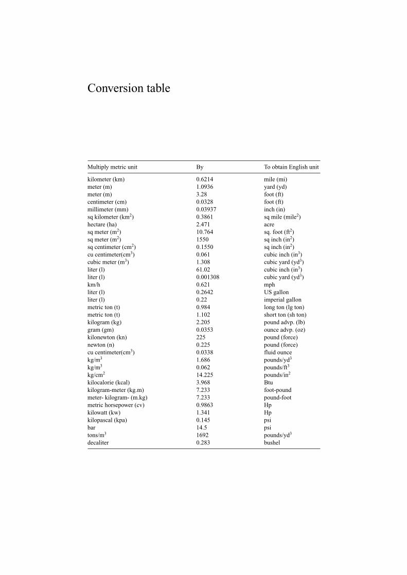
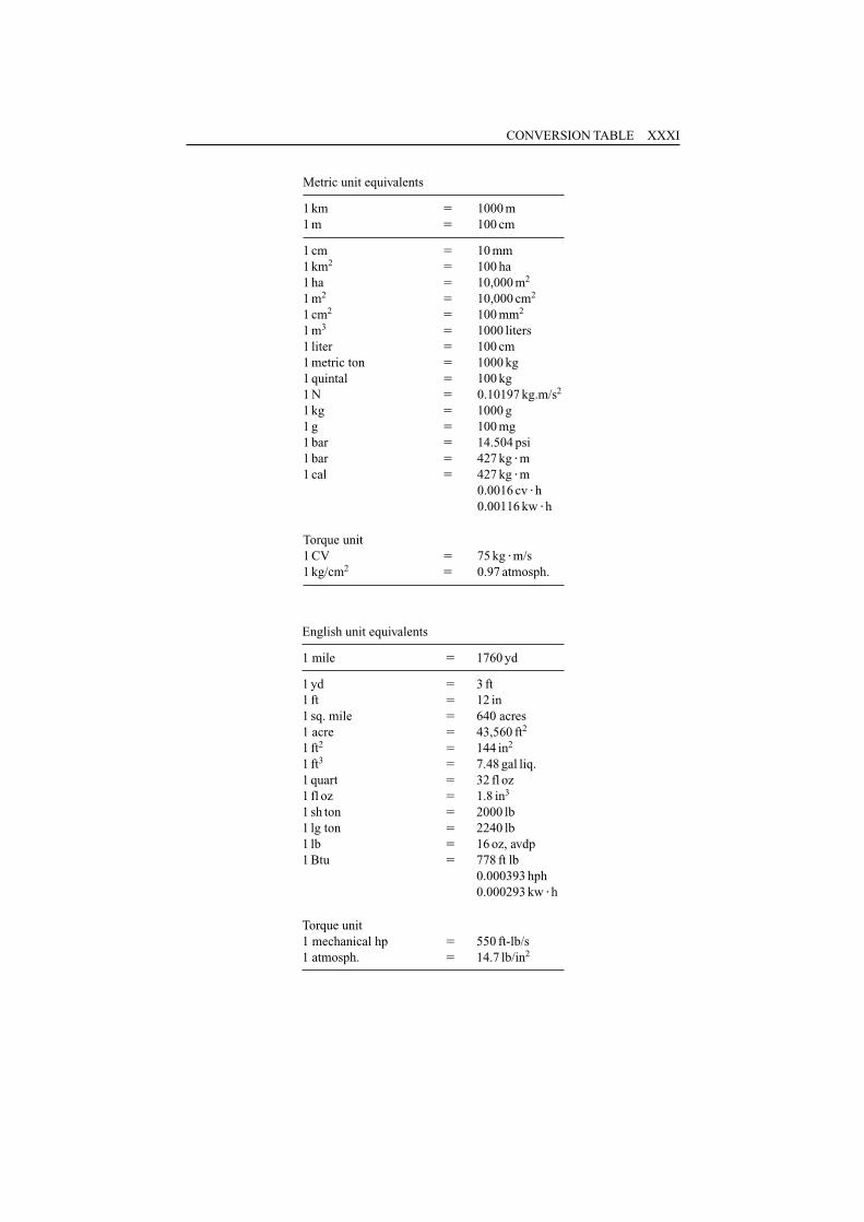
Conversion table
Multiply metric unit By To obtain English unit
kilometer (km) 0.6214 mile (mi)meter (m) 1.0936 yard (yd)meter (m) 3.28 foot (ft)centimeter (cm) 0.0328 foot (ft)millimeter (mm) 0.03937 inch (in)sq kilometer (km2) 0.3861 sq mile (mile2)hectare (ha) 2.471 acresq meter (m2) 10.764 sq. foot (ft2)sq meter (m2) 1550 sq inch (in2)sq centimeter (cm2) 0.1550 sq inch (in2)cu centimeter(cm3) 0.061 cubic inch (in3)cubic meter (m3) 1.308 cubic yard (yd3)liter (l) 61.02 cubic inch (in3)liter (l) 0.001308 cubic yard (yd3)km/h 0.621 mphliter (l) 0.2642 US gallonliter (l) 0.22 imperial gallonmetric ton (t) 0.984 long ton (lg ton)metric ton (t) 1.102 short ton (sh ton)kilogram (kg) 2.205 pound advp. (lb)gram (gm) 0.0353 ounce advp. (oz)kilonewton (kn) 225 pound (force)newton (n) 0.225 pound (force)cu centimeter(cm3) 0.0338 fluid ouncekg/m3 1.686 pounds/yd3
kg/m3 0.062 pounds/ft3
kg/cm2 14.225 pounds/in2
kilocalorie (kcal) 3.968 Btukilogram-meter (kg.m) 7.233 foot-poundmeter- kilogram- (m.kg) 7.233 pound-footmetric horsepower (cv) 0.9863 Hpkilowatt (kw) 1.341 Hpkilopascal (kpa) 0.145 psibar 14.5 psitons/m3 1692 pounds/yd3
decaliter 0.283 bushel
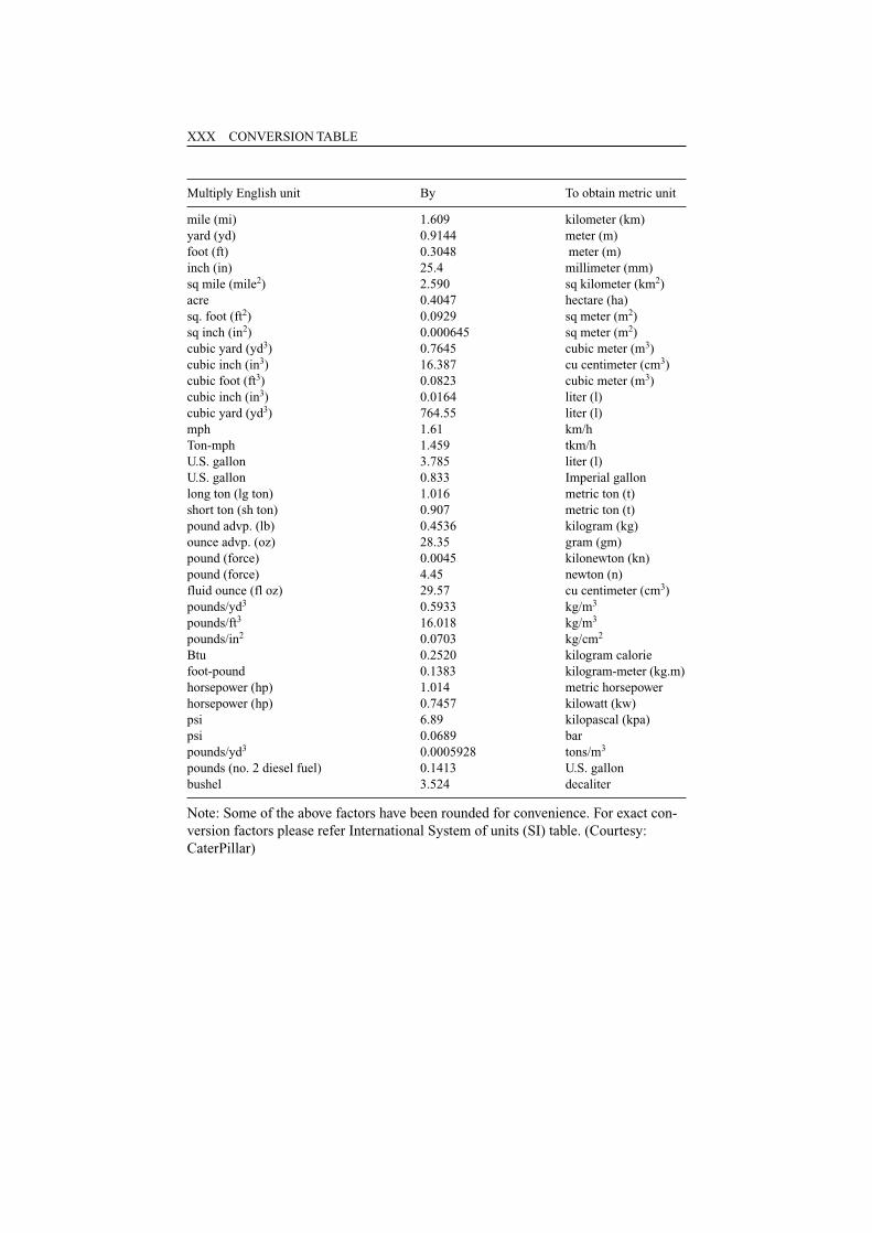
Multiply English unit By To obtain metric unit
mile (mi) 1.609 kilometer (km)yard (yd) 0.9144 meter (m)foot (ft) 0.3048 meter (m)inch (in) 25.4 millimeter (mm)sq mile (mile2) 2.590 sq kilometer (km2)acre 0.4047 hectare (ha)sq. foot (ft2) 0.0929 sq meter (m2)sq inch (in2) 0.000645 sq meter (m2)cubic yard (yd3) 0.7645 cubic meter (m3)cubic inch (in3) 16.387 cu centimeter (cm3)cubic foot (ft3) 0.0823 cubic meter (m3)cubic inch (in3) 0.0164 liter (l)cubic yard (yd3) 764.55 liter (l)mph 1.61 km/hTon-mph 1.459 tkm/hU.S. gallon 3.785 liter (l)U.S. gallon 0.833 Imperial gallonlong ton (lg ton) 1.016 metric ton (t)short ton (sh ton) 0.907 metric ton (t)pound advp. (lb) 0.4536 kilogram (kg)ounce advp. (oz) 28.35 gram (gm)pound (force) 0.0045 kilonewton (kn)pound (force) 4.45 newton (n)fluid ounce (fl oz) 29.57 cu centimeter (cm3)pounds/yd3 0.5933 kg/m3
pounds/ft3 16.018 kg/m3
pounds/in2 0.0703 kg/cm2
Btu 0.2520 kilogram calorie foot-pound 0.1383 kilogram-meter (kg.m)horsepower (hp) 1.014 metric horsepower horsepower (hp) 0.7457 kilowatt (kw)psi 6.89 kilopascal (kpa)psi 0.0689 barpounds/yd3 0.0005928 tons/m3
pounds (no. 2 diesel fuel) 0.1413 U.S. gallonbushel 3.524 decaliter
Note: Some of the above factors have been rounded for convenience. For exact con-version factors please refer International System of units (SI) table. (Courtesy:CaterPillar)
XXX CONVERSION TABLE
CONVERSION TABLE XXXI
Metric unit equivalents
1 km � 1000 m1 m � 100 cm
1 cm � 10 mm1 km2 � 100 ha1 ha � 10,000 m2
1 m2 � 10,000 cm2
1 cm2 � 100 mm2
1 m3 � 1000 liters1 liter � 100 cm1 metric ton � 1000 kg1 quintal � 100 kg1 N � 0.10197 kg.m/s2
1 kg � 1000 g1 g � 100 mg1 bar � 14.504 psi1 bar � 427 kg �m1 cal � 427 kg �m
0.0016 cv �h0.00116 kw �h
Torque unit1 CV � 75 kg �m/s1 kg/cm2 � 0.97 atmosph.
English unit equivalents
1 mile � 1760 yd
1 yd � 3 ft1 ft � 12 in1 sq. mile � 640 acres1 acre � 43,560 ft2
1 ft2 � 144 in2
1 ft3 � 7.48 gal liq.1 quart � 32 fl oz1 fl oz � 1.8 in3
1 sh ton � 2000 lb1 lg ton � 2240 lb1 lb � 16 oz, avdp1 Btu � 778 ft lb
0.000393 hph0.000293 kw �h
Torque unit1 mechanical hp � 550 ft-lb/s1 atmosph. � 14.7 lb/in2
XXXII CONVERSION TABLE
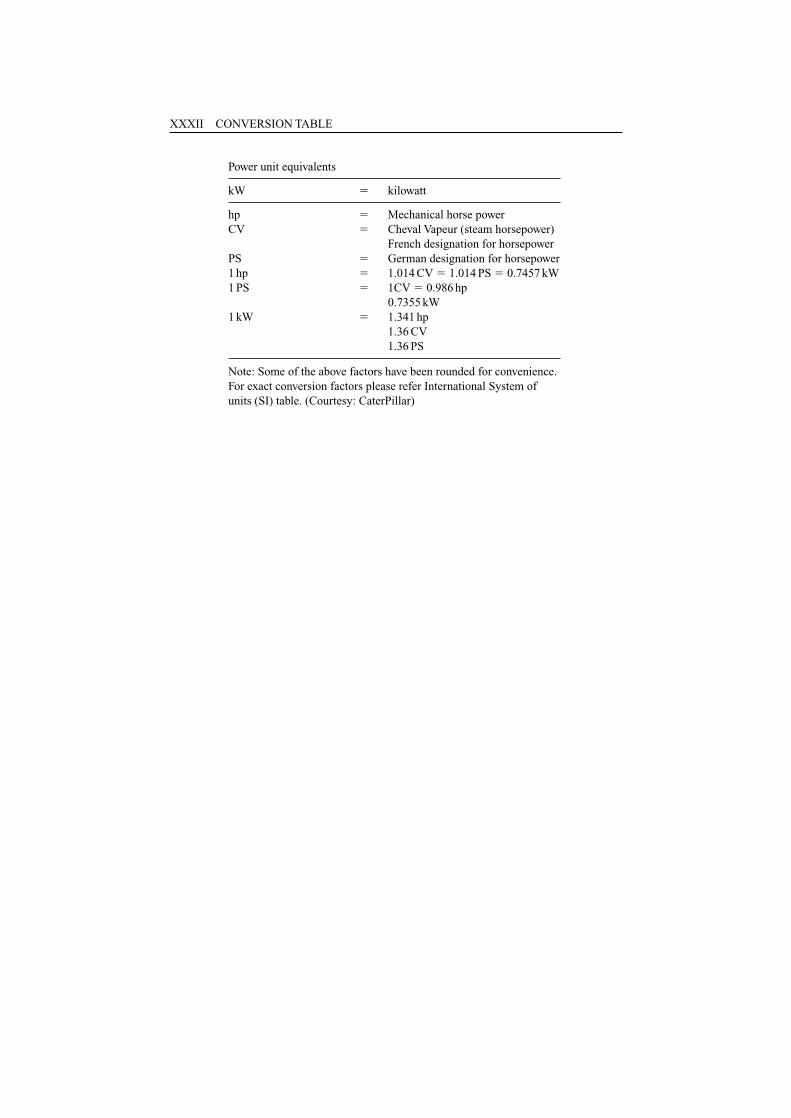
Power unit equivalents
kW � kilowatt
hp � Mechanical horse powerCV � Cheval Vapeur (steam horsepower)
French designation for horsepowerPS � German designation for horsepower1 hp � 1.014 CV � 1.014 PS � 0.7457 kW1 PS � 1CV � 0.986 hp
0.7355 kW1 kW � 1.341 hp
1.36 CV1.36 PS
Note: Some of the above factors have been rounded for convenience.For exact conversion factors please refer International System ofunits (SI) table. (Courtesy: CaterPillar)
1.1 EXCAVATIONS AND THEIR CLASSIFICATION
The meaning of word ‘excavate’ is to dislodge the rock massif from its original place(in-situ). This involves two operations: digging the ground and its disposal. This canbe carried out to any formation that exists within the earth crust. This operation cancreate openings or excavations of different sizes, shapes and configurations at thedesired location. The location could be a hilly terrain, plain ground, desert, cropland,forests or any other terrain than these. It could be within an urban land or at the coun-tryside and even sometimes within water-bodies or in the ground saturated with water.It could commence at, above or below the ground level or datum and extend in anydirection: horizontal, inclined, vertically up or down.
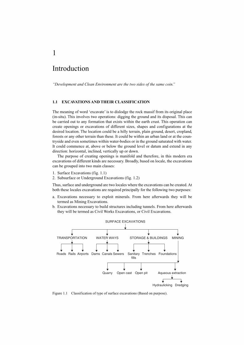
The purpose of creating openings is manifold and therefore, in this modern eraexcavations of different kinds are necessary. Broadly, based on locale, the excavationscan be grouped into two main classes:
1. Surface Excavations (fig. 1.1)2. Subsurface or Underground Excavations (fig. 1.2)
Thus, surface and underground are two locales where the excavations can be created. Atboth these locales excavations are required principally for the following two purposes:
a. Excavations necessary to exploit minerals. From here afterwards they will betermed as Mining Excavations.
b. Excavations necessary to build structures including tunnels. From here afterwardsthey will be termed as Civil Works Excavations, or Civil Excavations.
1
Introduction
“Development and Clean Environment are the two sides of the same coin.”
SURFACE EXCAVATIONS
STORAGE & BUILDINGS
Sewers Foundations
Aqueous extraction
Dredging
TRANSPORTATION WATER WAYS MINING
Roads Rails Airports Dams Canals Sanitaryfills
Trenches
Quarry Open cast Open pit
Hydraulicking
Figure 1.1 Classification of type of surface excavations (Based on purpose).
1.2 SURFACE EXCAVATIONS
The magnitude of surface excavations is many-fold than the underground excavationsdescribed in the succeeding paragraphs. It amounts to be billions of cubic meters ortonnage every year. This excavation is necessary; firstly, to remove enormous amountof rock material lying above a mineral deposits as overburden and also to produce use-ful minerals themselves at the mines, which could be open pits, opencasts or quarries.
Secondly, to remove enormous volume of earth-material while constructing rail routesand roadways, canals, dams and many vital civil constructions including buildings asshown in line diagram (fig. 1.1). In fact these are the development or infrastructures’building activities that are essential for the growth and prosperity of any country.
1.3 UNDERGROUND EXCAVATIONS
There are two locales where subsurface openings or tunnels are driven. First categoryincludes those tunnels or openings, which serve people by way of providing passageto rails, roads, navigation, pedestrian etc. and also for conveyance of water and serveas sewerage. These tunnels, constructed for civil works and having very long life, needto be very safe with regard to their stability, ventilation, illumination and risks of get-ting flooded etc. Globally, they are driven few thousand kilometers every year.
The second category of tunnels or openings is for the purpose of exploring andexploiting mineral deposits, which are deep-seated, and cannot be mined by surfacemining methods. These tunnels are small in size (cross section) but during the life ofa mine, their lengths totals to be hundreds of kilometers, and thus globally, severalthousand kilometers of tunnels of this kind are required to be driven every year. Forexample, Mount Isa Mines, which are largest copper, silver and zinc producing estab-lishment in Australia is having 975 km of underground openings (tunnels, raises and
2 SURFACE AND UNDERGROUND EXCAVATIONS
UNDERGROUND EXCAVATIONS (TUNNELS & OPENINGS)
Transportation/conveyance
Storage & plantexcavations
Protectionopenings
Car parksOil storage cavernsU/g power stationsMilitary stocksDisposal ofradioactive waste
SheltersControl posts
Exploratoryheadings
Undergroundmining
People & Goods– Pedestrian & cycle subways– Railways & metros– Highways
Water– Canals (u/g)– Hydroelectric power plants
Developmentdrives & openings
Stopedevelopment &
stoping
Pillarextraction &liquidation
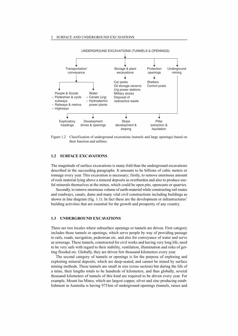
Figure 1.2 Classification of underground excavations (tunnels and large openings) based ontheir function and utilities.
shafts). Mine workings are extending within a span of 5 km long, 1.2 km wide, withdeepest point at 1800 m (depth) from surface.
In addition to tunnels, creation of large underground excavations is also mandatorymainly for two applications: first for exploitation of minerals, which are driven togetherwith mine tunnels, and secondly for the purpose of storage of oil (fig. 15.4), powergeneration (fig. 15.3), defense utilities, storing nuclear and hazardous wastes (fig. 15.5)and many others (figs 15.6, 15.7). Figure 1.2 classifies the subsurface openings, whichare essential and driven globally to the magnitude of millions of linear meters or billionsof cubic meters every year.
Figures 1.1 and 1.2 show breakup of excavations’ networks both for civil works andmining. The present trend is to go for more and more for such excavations and section 1.4reveals the reason behind this.
1.4 IMPORTANCE OF MINERALS AND BRIEF HISTORY TORECOVER THEM
Minerals are naturally occurring inorganic or organic substances and mining is aprocess to dig, excavate or extract them commercially. Minerals are one of the basicnatural resources and mining is as old as civilization and it was started some 300,000(B. C.) years9 ago with the search for some useful stones. According to needs of mandifferent minerals have been investigated in the different periods of history, and hence,the cultural ages of the man are associated with minerals or their derivatives and theyhave been termed as Stone Age, Bronze Age, Iron Age and Atomic Age. By the start ofChristian era all ‘Seven Metals of Antiquity’ namely copper, tin, gold, silver, lead, ironand mercury were known and mined.
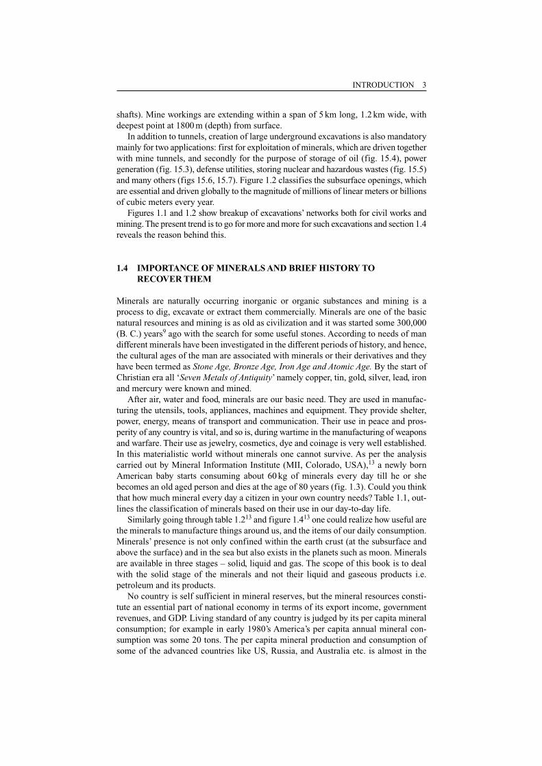
After air, water and food, minerals are our basic need. They are used in manufac-turing the utensils, tools, appliances, machines and equipment. They provide shelter,power, energy, means of transport and communication. Their use in peace and pros-perity of any country is vital, and so is, during wartime in the manufacturing of weaponsand warfare. Their use as jewelry, cosmetics, dye and coinage is very well established.In this materialistic world without minerals one cannot survive. As per the analysiscarried out by Mineral Information Institute (MII, Colorado, USA),13 a newly bornAmerican baby starts consuming about 60 kg of minerals every day till he or shebecomes an old aged person and dies at the age of 80 years (fig. 1.3). Could you thinkthat how much mineral every day a citizen in your own country needs? Table 1.1, out-lines the classification of minerals based on their use in our day-to-day life.
Similarly going through table 1.213 and figure 1.413 one could realize how useful arethe minerals to manufacture things around us, and the items of our daily consumption.Minerals’ presence is not only confined within the earth crust (at the subsurface andabove the surface) and in the sea but also exists in the planets such as moon. Mineralsare available in three stages – solid, liquid and gas. The scope of this book is to dealwith the solid stage of the minerals and not their liquid and gaseous products i.e.petroleum and its products.
No country is self sufficient in mineral reserves, but the mineral resources consti-tute an essential part of national economy in terms of its export income, governmentrevenues, and GDP. Living standard of any country is judged by its per capita mineralconsumption; for example in early 1980’s America’s per capita annual mineral con-sumption was some 20 tons. The per capita mineral production and consumption ofsome of the advanced countries like US, Russia, and Australia etc. is almost in the
INTRODUCTION 3
4 SURFACE AND UNDERGROUND EXCAVATIONS
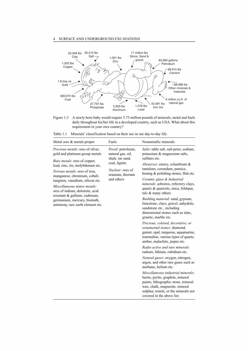
Table 1.1 Minerals’ classification based on their use in our day-to-day life.
Metal ores & metals proper Fuels Nonmetallic minerals
17 million lbsStone, Sand &
gravel 83,890 gallonsPetroleum
68,915 lbsCement
�68,088 lbsOther minerals &
materials
6 million cu.ft. ofnatural gas42,581 lbs
Iron ore1,078 lbsLead
5,929 lbsAluminum
27,797 lbsPhosphate
23,048 lbsClay
1,925 lbsCopper
1.8 tray oz.Gold
589,974 lbsCoal
30,415 lbsSalt 1,001 lbs
Zinc
Figure 1.3 A newly born baby would require 3.75 million pounds of minerals, metal and fuelsdaily throughout his/her life in a developed country, such as USA. What about thisrequirement in your own country?
Precious metals: ores of silver,gold and platinum-group metals
Base metals: ores of copper, lead, zinc, tin, molybdenum etc.
Ferrous metals: ores of iron,manganese, chromium, cobalt,tungsten, vanadium, silicon etc.
Miscellaneous minor metals:ores of indium, dolomite, acid resistant & gallium, cadmium,germanium, mercury, bismuth,antimony, rare earth element etc.
Fossil: petroleum,natural gas, oil,shale, tar sand,coal, lignite
Nuclear: ores ofuranium, thoriumand others
Salts: table salt, salt-peter, sodium,potassium & magnesium salts,sulfates etc.
Abrasives: emery, columbium &tantalum, corundum, pumice,honing & polishing stones, flint etc.
Ceramic glass & Industrialminerals: asbestos, refectory clays,quartz & quartzite, mica, feldspar,talc & many others
Building material: sand, gypsum,limestone, clays, gravel, anhydrite,sandstone etc., includingdimensional stones such as slate,granite, marble etc.
Precious, colored, decorative, orornamental stones: diamond,garnet, opal, turquoise, aquamarine,tourmaline, various types of quartz,amber, malachite, jasper etc.
Radio active and rare minerals:radium, lithium, rubidium etc.
Natural gases: oxygen, nitrogen,argon, and other rare gases such asmethane, helium etc.
Miscellaneous industrial minerals:barite, pyrite, graphite, mineralpaints, lithographic stone, mineralwax, chalk, magnesite, mineralsulphur, trinoli, or the minerals notcovered in the above list.
INTRODUCTION 5
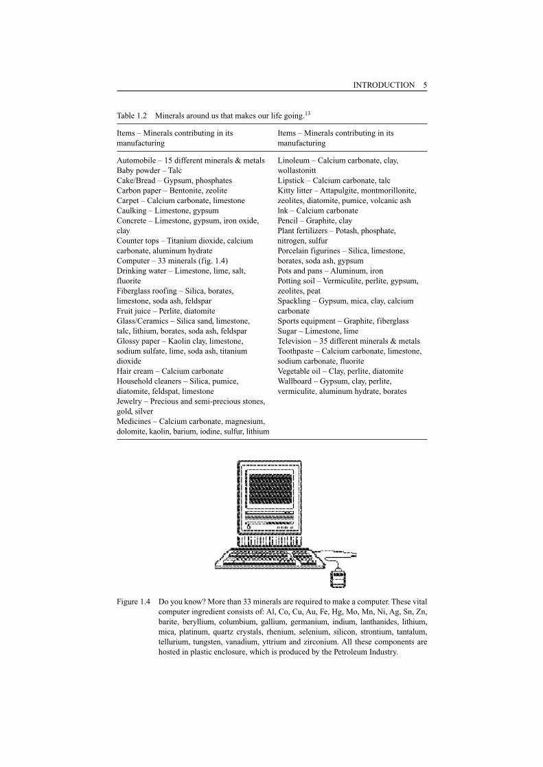
Table 1.2 Minerals around us that makes our life going.13
Items – Minerals contributing in its Items – Minerals contributing in itsmanufacturing manufacturing
Automobile – 15 different minerals & metals Linoleum – Calcium carbonate, clay,Baby powder – Talc wollastonittCake/Bread – Gypsum, phosphates Lipstick – Calcium carbonate, talcCarbon paper – Bentonite, zeolite Kitty litter – Attapulgite, montmorillonite,Carpet – Calcium carbonate, limestone zeolites, diatomite, pumice, volcanic ashCaulking – Limestone, gypsum lnk – Calcium carbonateConcrete – Limestone, gypsum, iron oxide, Pencil – Graphite, clayclay Plant fertilizers – Potash, phosphate, Counter tops – Titanium dioxide, calcium nitrogen, sulfurcarbonate, aluminum hydrate Porcelain figurines – Silica, limestone,Computer – 33 minerals (fig. 1.4) borates, soda ash, gypsumDrinking water – Limestone, lime, salt, Pots and pans – Aluminum, ironfluorite Potting soil – Vermiculite, perlite, gypsum,Fiberglass roofing – Silica, borates, zeolites, peatlimestone, soda ash, feldspar Spackling – Gypsum, mica, clay, calciumFruit juice – Perlite, diatomite carbonateGlass/Ceramics – Silica sand, limestone, Sports equipment – Graphite, fiberglasstalc, lithium, borates, soda ash, feldspar Sugar – Limestone, limeGlossy paper – Kaolin clay, limestone, Television – 35 different minerals & metalssodium sulfate, lime, soda ash, titanium Toothpaste – Calcium carbonate, limestone,dioxide sodium carbonate, fluoriteHair cream – Calcium carbonate Vegetable oil – Clay, perlite, diatomiteHousehold cleaners – Silica, pumice, Wallboard – Gypsum, clay, perlite,diatomite, feldspat, limestone vermiculite, aluminum hydrate, boratesJewelry – Precious and semi-precious stones,gold, silver Medicines – Calcium carbonate, magnesium, dolomite, kaolin, barium, iodine, sulfur, lithium
Figure 1.4 Do you know? More than 33 minerals are required to make a computer. These vitalcomputer ingredient consists of: Al, Co, Cu, Au, Fe, Hg, Mo, Mn, Ni, Ag, Sn, Zn,barite, beryllium, columbium, gallium, germanium, indium, lanthanides, lithium,mica, platinum, quartz crystals, rhenium, selenium, silicon, strontium, tantalum,tellurium, tungsten, vanadium, yttrium and zirconium. All these components arehosted in plastic enclosure, which is produced by the Petroleum Industry.

same ratio, or even the consumption is higher than production. The reason is that fromminerals, which are the basic raw materials, value added products prepared in thesecountries. This strategy has multiple positive effects to boost economy. Any country,which is an extremely poor mineral producer and consumer, reflects its very weakindustrial growth and infrastructures.
This should be born in mind that the ground or rock formations vary from place toplace and even within the same place, hence, the same technique, method or equip-ment can not be applied every where.
1.5 CURRENT STATUS OF MINERAL INDUSTRY
Today products of mineral industry pervade the lives of all mankind. Looking at theglobal scenario, the progress that has been made in the process of mineral explorationand exploitation in the last five decades was not matched even during last five cen-turies. This was made possible by the application of advanced technology to fulfill theneeds of the rapid industrial growth and increasing population of the world.
There is a tough competition of the minerals and metal prices in the world market,which again is a setback for the minerals any country exports or in a surplus position.Most of the developed countries of the world are far ahead with regard to mineral pro-duction, consumption, import, export, technological development, productivity andmany other vital spheres than those countries which are undeveloped and developing.Even at the domestic front mineral industry’s share in the gross domestic product(GDP) comparing with other industries such as petroleum, agriculture, manufactur-ing, trading etc. should be considerable. It is obvious, therefore, if any country has notto sink into downward economic trend, its mineral resources should be tapped, chan-neled and kept motivated to bridge the gap in the spheres outlined above.
1.6 EXCAVATION TECHNOLOGIES/SYSTEMS – DEVELOPMENT &GROWTH
As stated above that a mineral has got three physical states – solid, liquid and gaseous form and the solid minerals can be further divided as metals, non-metals and fuels. This aspect makes the scope of mining and hence, excavation technologyvery wide.
Ancient miners used basic versions of many modern tools, appliances and equip-ment (fig. 1.6). Rock was mostly dislodged in-situ from hammers and wedges and theresultant lumps were eased by pick or crowbar. Use of iron hammers with chisel orwedges were also made to break the rock. Iron shovels with wooden handles were usedto muck out the broken spoil. In some cases the method of fire setting (i.e. first heat-ing the hard rock and then cooling it by the cold water causing it to break), introducedin prehistoric times, was used to break down very hard rocks. Tools17 were generallymade of iron, copper or bronze, although Romans miners sometimes used stone ham-mers. All tools were appeared to have short handle to facilitate their use in narrowcramped working places.
But during the period in between ancient times and particularly after 19th centurythere have been many important events, inventions and developments that have resultedthe new techniques, methods and equipment. This scenario has brought the mineralindustry in the forefront to feed the requirements of masses. This can be verified by
6 SURFACE AND UNDERGROUND EXCAVATIONS
the facts that as how the equipment, techniques and methods that have been describedin the following chapters, could achieve this?
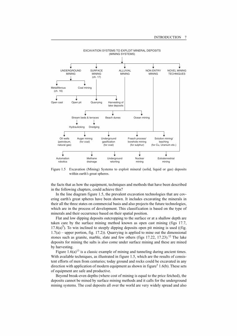
In the line diagram figure 1.5, the prevalent excavation technologies that are cov-ering earth’s great spheres have been shown. It includes excavating the minerals intheir all the three states on commercial basis and also projects the future technologies,which are in the process of development. This classification is based on the type ofminerals and their occurrence based on their spatial position.
Flat and low dipping deposits outcropping to the surface or at a shallow depth aretaken care by the surface mining method known as open cast mining (figs 17.7,17.8(a)7). To win inclined to steeply dipping deposits open pit mining is used ((fig.1.7(a) – upper portion, fig. 17.2)). Quarrying is applied to mine out the dimensionalstones such as granite, marble, slate and few others (figs 17.22, 17.23).12 The lakedeposits for mining the salts is also come under surface mining and these are minedby harvesting.
Figure 1.6(a)13 is a classic example of mining and tunneling during ancient times.With available techniques, as illustrated in figure 1.5, which are the results of consis-tent efforts of men from centuries; today ground and rocks could be excavated in anydirection with application of modern equipment as shown in figure5 1.6(b). These setsof equipment are safe and productive.
Beyond break-even depths (where cost of mining is equal to the price fetched), thedeposits cannot be mined by surface mining methods and it calls for the undergroundmining systems. The coal deposits all over the world are very widely spread and also
INTRODUCTION 7
EXCAVATION SYSTEMS TO EXPLOIT MINERAL DEPOSITS(MINING SYSTEMS)
UNDERGROUNDMINING
NON ENTRYMINING
Metalliferous(ch. 16)
Coal mining
Open pit Quarrying Harvesting oflake deposits
Beach dunes Ocean mining
Hydraulicking Dredging
Undergroundgasification(for coal)
Frasch process/borehole mining
(for sulphur)
Solution mining/leaching
(for Cu, Uranium etc.)
Methanedrainage
Nuclearmining
SURFACEMINING(ch. 17)
ALLUVIALMINING
NOVEL MININGTECHNIQUES
Open cast
Stream beds & terraces
Oil wells(petroleum,natural gas)
Auger mining(for coal)
Automationrobotics
Undergroundretorting
Extraterrestrialmining
Figure 1.5 Excavation (Mining) Systems to exploit mineral (solid, liquid or gas) depositswithin earth’s great spheres.
extends beneath the surface, and that is why, they have been separated from the rest ofthe minerals and are won by underground coal mining methods (figs 16.3, 16.5 to16.7, 16.23). This type of mining calls for a special care and attention towards groundcontrol, fire, explosion and inundation. It needs a special type of safety culture, thanmining rest of minerals, which comes under underground metal mining (chapter 16).
In underground metal mining situation ground fragmentation is one of the mainworries of a mining engineer. The strength of ore and its enclosing rocks, dip andthickness of the deposit govern the mining methods under this system. These methods(fig. 1.7(a)2) fall under three main categories – unsupported, artificially supported andcaving methods, as described in chapter 16. In this mining system with the increase indepth the problem of heat, humidity, haulage, hoisting and rock burst increases.
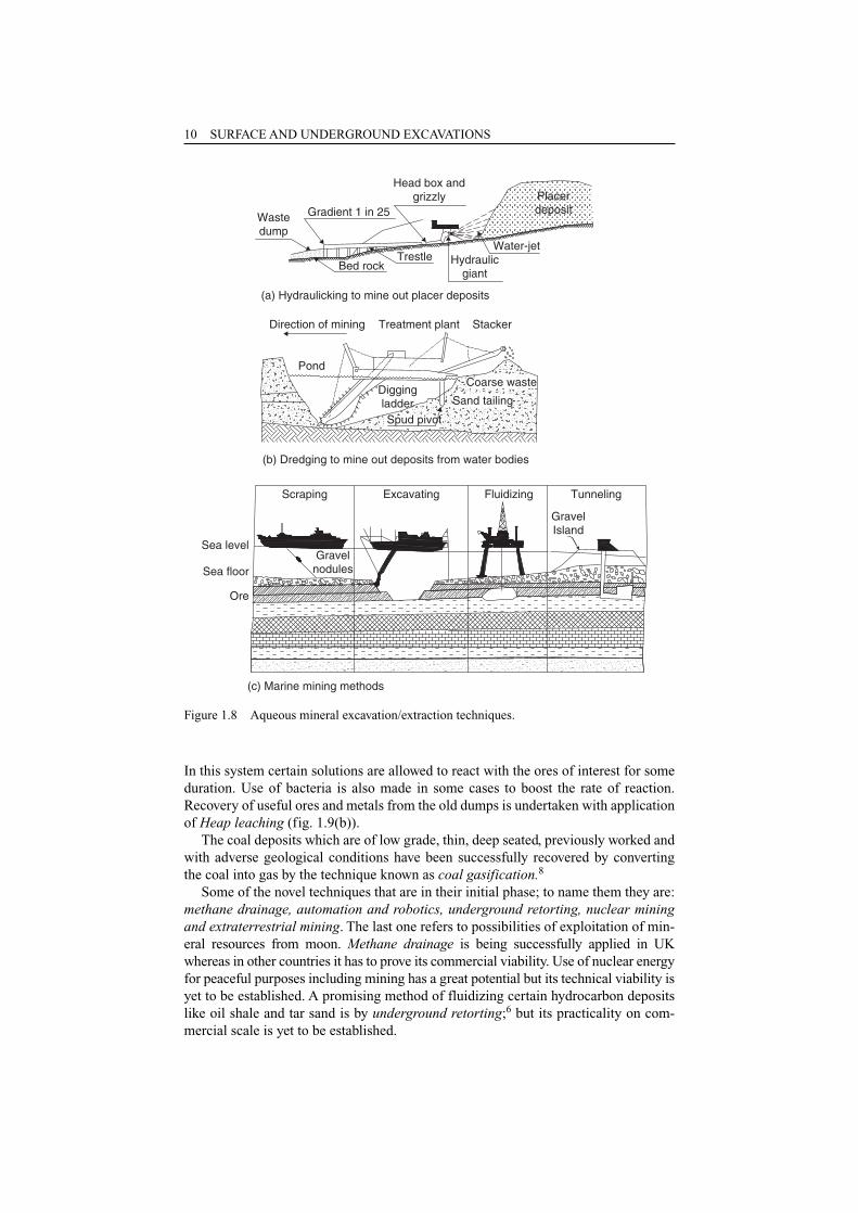
Deposits saturated with water, and under the water bodies including ocean are recov-ered by alluvial mining. Dredging – a floating vessel equipped with dislodging, or exca-vating, loading and processing mechanisms is essentially a prevalent method to minethe deposits under a water-body (fig. 1.8(b)3). Hydraulicking – a method, to mine out placer deposits (fig. 1.8(a)). Scraping, Excavating, Fluidizing and Tunneling(fig. 1.8(c)3) could be applied to excavate deep-seated marine deposits. Application ofthese methods on commercial scale is yet to be established.
No entry mining is very widely undertaken; and mining of petroleum and gas is so wide that this branch of mining system has been separately dealt as petroleum andnatural gas engineering.
8 SURFACE AND UNDERGROUND EXCAVATIONS
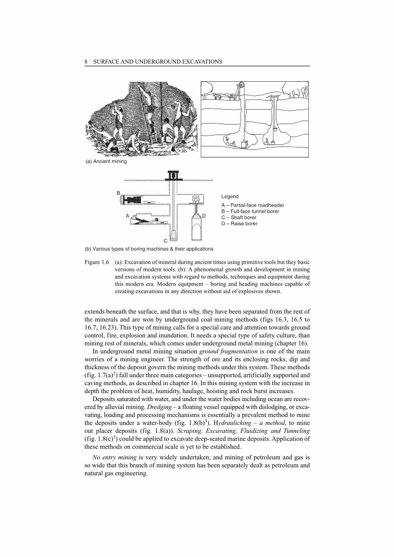
(b) Various types of boring machines & their applications
Legend
A – Partial-face roadheaderB – Full-face tunnel borerC – Shaft borerD – Raise borer
B
D
C
A
(a) Ancient mining
Figure 1.6 (a): Excavation of mineral during ancient times using primitive tools but they basicversions of modern tools. (b): A phenomenal growth and development in miningand excavation systems with regard to methods, techniques and equipment duringthis modern era. Modern equipment – boring and heading machines capable ofcreating excavations in any direction without aid of explosives shown.
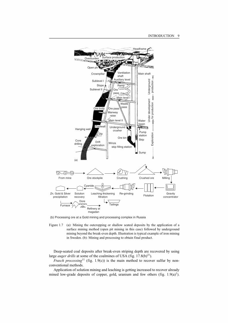
INTRODUCTION 9
From mine Ore stockpile Crushing Crushed ore Milling
GravityconcentratorFlotation
Re-grinding
Tailings
Leaching thickeningfiltration
Cyanide
Solutionrecovery
Furnace
Dore
Refinery atmagadan
(b) Processing ore at a Gold mining and processing complex in Russia
Zn. Gold & Silverprecipitation
Headframe
Surface productionOverburden
Open pit
Crownpillar Ventilationshaft
Auxiliary level
Ramp
Main shaft
Orepass
Main level I
WastepassOre passOre body
Hanging wallFootwall Underground
crusher
Ore binCore
drilling
(a)
Driftexploration
Dip
Winzeskip filling station
Sump
Skip
Pumpstation
Waterbasin
Exp
lora
tion
Und
er d
evel
opm
ent
for
prod
uctio
nU
nder
grou
ndpr
oduc
tion
Manwayraise
Main level II
Sublevel I
Stope
Sublevel II
Fan
Figure 1.7 (a): Mining the outcropping or shallow seated deposits by the application of asurface mining method (open pit mining in this case) followed by undergroundmining beyond the break-even depth. Illustration is typical example of iron miningin Sweden. (b): Mining and processing to obtain final product.
Deep-seated coal deposits after break-even striping depth are recovered by usinglarge auger drills at some of the coalmines of USA (fig. 17.8(b)21).
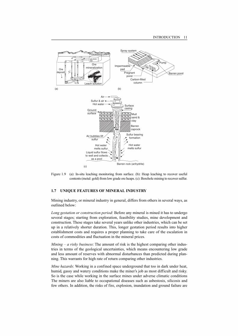
Frasch processing11 (fig. 1.9(c)) is the main method to recover sulfur by non-conventional methods.
Application of solution mining and leaching is getting increased to recover alreadymined low-grade deposits of copper, gold, uranium and few others (fig. 1.9(a)1).
In this system certain solutions are allowed to react with the ores of interest for someduration. Use of bacteria is also made in some cases to boost the rate of reaction.Recovery of useful ores and metals from the old dumps is undertaken with applicationof Heap leaching (fig. 1.9(b)).
The coal deposits which are of low grade, thin, deep seated, previously worked andwith adverse geological conditions have been successfully recovered by convertingthe coal into gas by the technique known as coal gasification.8
Some of the novel techniques that are in their initial phase; to name them they are:methane drainage, automation and robotics, underground retorting, nuclear miningand extraterrestrial mining. The last one refers to possibilities of exploitation of min-eral resources from moon. Methane drainage is being successfully applied in UKwhereas in other countries it has to prove its commercial viability. Use of nuclear energyfor peaceful purposes including mining has a great potential but its technical viability isyet to be established. A promising method of fluidizing certain hydrocarbon depositslike oil shale and tar sand is by underground retorting;6 but its practicality on com-mercial scale is yet to be established.
10 SURFACE AND UNDERGROUND EXCAVATIONS
Gradient 1 in 25
Head box andgrizzly
Wastedump
Bed rockTrestle Hydraulic
giant
Water-jet
(a) Hydraulicking to mine out placer deposits
Placerdeposit
Sand tailing
Spud pivot
Diggingladder
Pond
Direction of mining Treatment plant
(b) Dredging to mine out deposits from water bodies
Scraping Excavating Fluidizing Tunneling
Sea level
Sea floor
Ore
(c) Marine mining methods
GravelIsland
Gravelnodules
Stacker
Coarse waste
Figure 1.8 Aqueous mineral excavation/extraction techniques.
1.7 UNIQUE FEATURES OF MINERAL INDUSTRY
Mining industry, or mineral industry in general, differs from others in several ways, asoutlined below:
Long gestation or construction period: Before any mineral is mined it has to undergoseveral stages; starting from exploration, feasibility studies, mine development andconstruction. These stages take several years unlike other industries, which can be setup in a relatively shorter duration. This, longer gestation period results into higherestablishment costs and requires a proper planning to take care of the escalation incosts of commodities and fluctuation in the mineral prices.
Mining – a risky business: The amount of risk is the highest comparing other indus-tries in terms of the geological uncertainties, which means encountering low gradeand less amount of reserves with abnormal disturbances than predicted during plan-ning. This warrants for high rate of return comparing other industries.
Mine hazards: Working in a confined space underground that too in dark under heat,humid, gassy and watery conditions make the miner’s job as most difficult and risky.So is the case while working in the surface mines under adverse climatic conditionsThe miners are also liable to occupational diseases such as asbestosis, silicosis andfew others. In addition, the risks of fire, explosion, inundation and ground failure are
INTRODUCTION 11
Leach solution
Oremineralization
(a)
Oredeposit
Processing plant
Pump
(b)
Impermeablepad
Pregnantpond
Carbon-filledcolumn
Barren pond
Spray system
Air
Sulfur & airHot water Surface
casingGroundsurface Mu
sand &clay
d
Barrencaprock
Air bubbles liftsulfur
Sulfur bearing
formation
Liquid sulfur flowsto well and collects
as a pool
Barren rock (anhydrite)(c)
Hot watermelts sulfur
Hot watermelts sulfur
Figure 1.9 (a): In-situ leaching monitoring from surface. (b): Heap leaching to recover usefulcontents (metal: gold) from low grade ore heaps. (c): Borehole mining to recover sulfur.
part and parcel of this industry. This makes mining operations less attractive so far thejob selection is concerned and warrants higher wages and more benefits to the workers.
Mineral reserve – a diminishing asset: The ore reserves get depleted every day oncemining is begun and they cannot be replenished. Therefore, any deposit or mine has adefinite life, and after which, the resources used in terms of man, machine, equipmentand infrastructures have to be diverted. This results in financial losses and makes amining venture less attractive to an entrepreneur. On the contrary any other industrycan be run continuously so far the basic raw materials are fed to it.
In fact mineral resources belong to all mankind, present and future, and should not besquandered. Thus, mining has strong ethical side to it. The miner must be educated to beaware of it. This means that at the time of geological prospecting proper evaluation ofore reserves and during mining and processing, maximum recovery must be ensured.
Access to the deposit, location of mines and working faces/spots: Usually access to anydeposit is difficult due to its location in a remote area. This, in turn, warrants establish-ment of proper infrastructures including the welfare facilities for the workers in thatlocality, and not only this, even within a mine the working spots/faces get change and aminer encounters a new environment of work like a soldier gets on a war front. A minerhas to fight always against the nature, and that is why, the term ‘winning a deposit’whichis used to mine-out a deposit, is very common in mining. All these aspects make miner’sjob challenging. On the contrary, most of other industries can be setup anywhere as perthe convenience and a worker is not required to change his working spot. On the samelines, Lineberry and Paolini10 describes the worst case in underground mining is the‘encumbered space’. This is due to the fact that in an underground situation the workingspace is inherently tight, distorted, congested, isolated and inaccessible, of poor quality,and deteriorating. These adverse conditions endanger personnel, damage mobile equip-ment, and affect all activities. The same is true even for the surface mines.
Mining a transitory activity: Different from civil engineers who are conditioned to designand build works/structures that are robust enough to last centuries; whereas, miningengineers must design their ‘permanent’ works to last mine lifetime and no more. Anyextension in safety or life length is an increase in cost and less profit, and this ultimatelyamounts raising the cutoff grade, and thereby recoverable reserves of a deposit.
Environmental impacts: Mining to processing to a get the final product is a complexoperation. First ore is mined from surface or/and underground mines. Thus to produceany end-product from a mineral deposit is a long process. There are several stagesafter mining and they are: Concentration (crushing, grinding, separation, classification,leaching, thickening, drying, etc.), Smelting, Refining and Casting etc.4 as shown infigure 1.7(b). Mining as well as extractive metallurgical operations are detrimental tothe environment. Land degradation, water and air pollution, change in the land use,disturbance to flora and fauna in and around the area occupied by the mining lease; aresome of the inherent features of mining which can not be avoided but their adverseimpact can only be minimized. This may be noted that any mining venture that is notable to pay to control the environmental impact and for land reclamation at the end ofoperation, is not feasible.
Mining must be performed as an economic activity: Mining must be performed as an economic activity that is to say at profit. Management must be careful and efficient,particularly in this era, where consumer demand and international recession make min-erals a buyer market. Mining operations must adjust to this difficult reality to survive.
12 SURFACE AND UNDERGROUND EXCAVATIONS
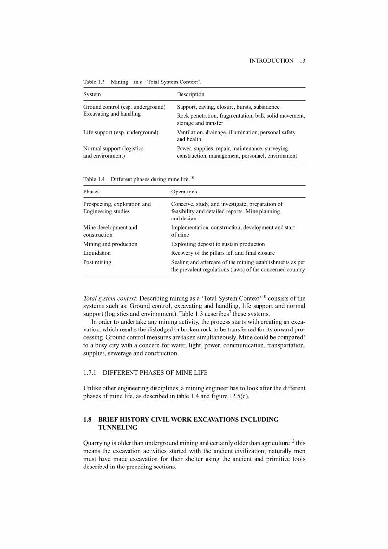
Total system context: Describing mining as a ‘Total System Context’10 consists of thesystems such as: Ground control, excavating and handling, life support and normalsupport (logistics and environment). Table 1.3 describes7 these systems.
In order to undertake any mining activity, the process starts with creating an exca-vation, which results the dislodged or broken rock to be transferred for its onward pro-cessing. Ground control measures are taken simultaneously. Mine could be compared7
to a busy city with a concern for water, light, power, communication, transportation,supplies, sewerage and construction.
1.7.1 DIFFERENT PHASES OF MINE LIFE
Unlike other engineering disciplines, a mining engineer has to look after the differentphases of mine life, as described in table 1.4 and figure 12.5(c).
1.8 BRIEF HISTORY CIVIL WORK EXCAVATIONS INCLUDINGTUNNELING
Quarrying is older than underground mining and certainly older than agriculture12 thismeans the excavation activities started with the ancient civilization; naturally menmust have made excavation for their shelter using the ancient and primitive toolsdescribed in the preceding sections.
INTRODUCTION 13
Table 1.3 Mining – in a ‘ Total System Context’.
System Description
Ground control (esp. underground) Support, caving, closure, bursts, subsidenceExcavating and handling Rock penetration, fragmentation, bulk solid movement,
storage and transfer
Life support (esp. underground) Ventilation, drainage, illumination, personal safetyand health
Normal support (logistics Power, supplies, repair, maintenance, surveying, and environment) construction, management, personnel, environment
Table 1.4 Different phases during mine life.10
Phases Operations
Prospecting, exploration and Conceive, study, and investigate; preparation ofEngineering studies feasibility and detailed reports. Mine planning
and design
Mine development and Implementation, construction, development and start construction of mine
Mining and production Exploiting deposit to sustain production
Liquidation Recovery of the pillars left and final closure
Post mining Sealing and aftercare of the mining establishments as perthe prevalent regulations (laws) of the concerned country
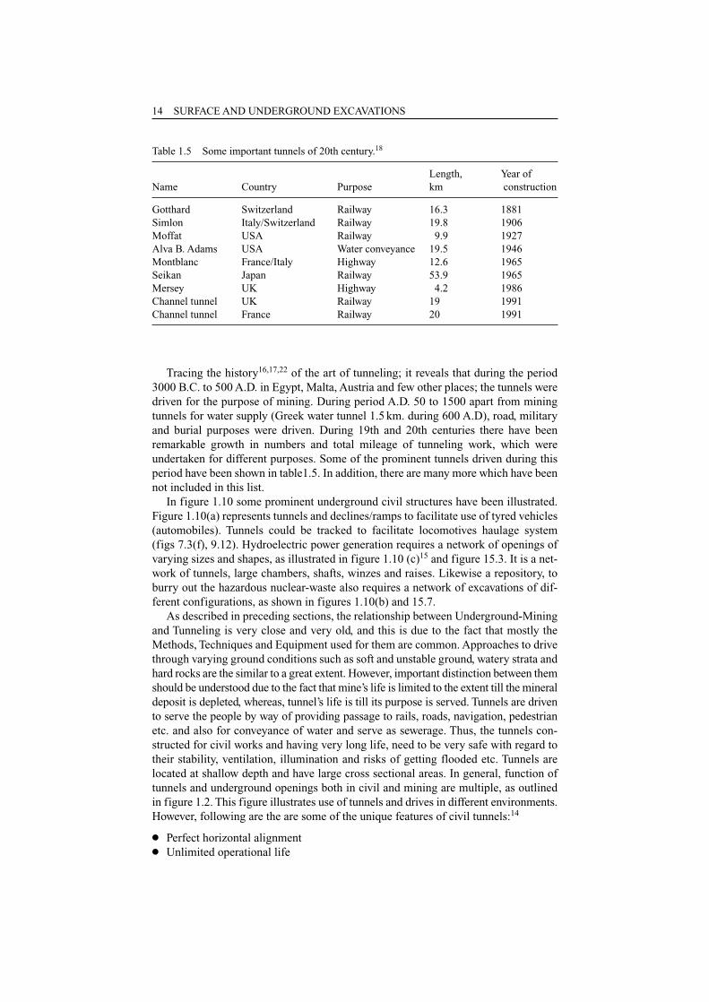
Tracing the history16,17,22 of the art of tunneling; it reveals that during the period3000 B.C. to 500 A.D. in Egypt, Malta, Austria and few other places; the tunnels weredriven for the purpose of mining. During period A.D. 50 to 1500 apart from miningtunnels for water supply (Greek water tunnel 1.5 km. during 600 A.D), road, militaryand burial purposes were driven. During 19th and 20th centuries there have beenremarkable growth in numbers and total mileage of tunneling work, which wereundertaken for different purposes. Some of the prominent tunnels driven during thisperiod have been shown in table1.5. In addition, there are many more which have beennot included in this list.
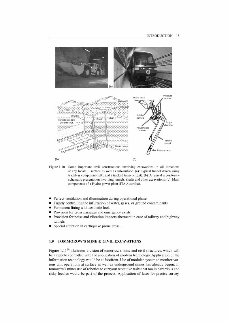
In figure 1.10 some prominent underground civil structures have been illustrated.Figure 1.10(a) represents tunnels and declines/ramps to facilitate use of tyred vehicles(automobiles). Tunnels could be tracked to facilitate locomotives haulage system (figs 7.3(f), 9.12). Hydroelectric power generation requires a network of openings ofvarying sizes and shapes, as illustrated in figure 1.10 (c)15 and figure 15.3. It is a net-work of tunnels, large chambers, shafts, winzes and raises. Likewise a repository, toburry out the hazardous nuclear-waste also requires a network of excavations of dif-ferent configurations, as shown in figures 1.10(b) and 15.7.
As described in preceding sections, the relationship between Underground-Miningand Tunneling is very close and very old, and this is due to the fact that mostly theMethods, Techniques and Equipment used for them are common. Approaches to drivethrough varying ground conditions such as soft and unstable ground, watery strata andhard rocks are the similar to a great extent. However, important distinction between themshould be understood due to the fact that mine’s life is limited to the extent till the mineraldeposit is depleted, whereas, tunnel’s life is till its purpose is served. Tunnels are drivento serve the people by way of providing passage to rails, roads, navigation, pedestrianetc. and also for conveyance of water and serve as sewerage. Thus, the tunnels con-structed for civil works and having very long life, need to be very safe with regard totheir stability, ventilation, illumination and risks of getting flooded etc. Tunnels arelocated at shallow depth and have large cross sectional areas. In general, function oftunnels and underground openings both in civil and mining are multiple, as outlinedin figure 1.2. This figure illustrates use of tunnels and drives in different environments.However, following are the are some of the unique features of civil tunnels:14
● Perfect horizontal alignment● Unlimited operational life
14 SURFACE AND UNDERGROUND EXCAVATIONS
Table 1.5 Some important tunnels of 20th century.18
Length, Year ofName Country Purpose km construction
Gotthard Switzerland Railway 16.3 1881Simlon Italy/Switzerland Railway 19.8 1906Moffat USA Railway 9.9 1927Alva B. Adams USA Water conveyance 19.5 1946Montblanc France/Italy Highway 12.6 1965Seikan Japan Railway 53.9 1965Mersey UK Highway 4.2 1986Channel tunnel UK Railway 19 1991Channel tunnel France Railway 20 1991
INTRODUCTION 15
300 m
Store room
Experimental chambers
(b) (c)
Shaft I
Area for future development
Approach road
Intake canalPressuretunnels
Intaketunnels
Powerhousecavern
Surgechamber
Tailracetunnel
Tailrace canal
(a)
Shaft IIIShaft II
Remote handlingof study shaft
600
m
Water pump
Figure 1.10 Some important civil constructions involving excavations in all directions at any locale – surface as well as sub-surface. (a): Typical tunnel driven usingtrackless equipment (left), and a tracked tunnel (right). (b): A typical repository –schematic presentation involving tunnels, shafts and other excavations. (c): Maincomponents of a Hydro-power plant (ITA Australia).
● Perfect ventilation and illumination during operational phase● Tightly controlling the infiltration of water, gases, or ground contaminants● Permanent lining with aesthetic look● Provision for cross passages and emergency exists● Provision for noise and vibration impacts abetment in case of railway and highway
tunnels● Special attention in earthquake prone areas.
1.9 TOMMOROW’S MINE & CIVIL EXCAVATIONS
Figure 1.1120 illustrates a vision of tomorrow’s mine and civil structures, which willbe a remote controlled with the application of modern technology. Application of theinformation technology would be at forefront. Use of modular system to monitor var-ious unit operations at surface as well as underground mines has already begun. Intomorrow’s mines use of robotics to carryout repetitive tasks that too in hazardous andrisky locales would be part of the process. Application of laser for precise survey,
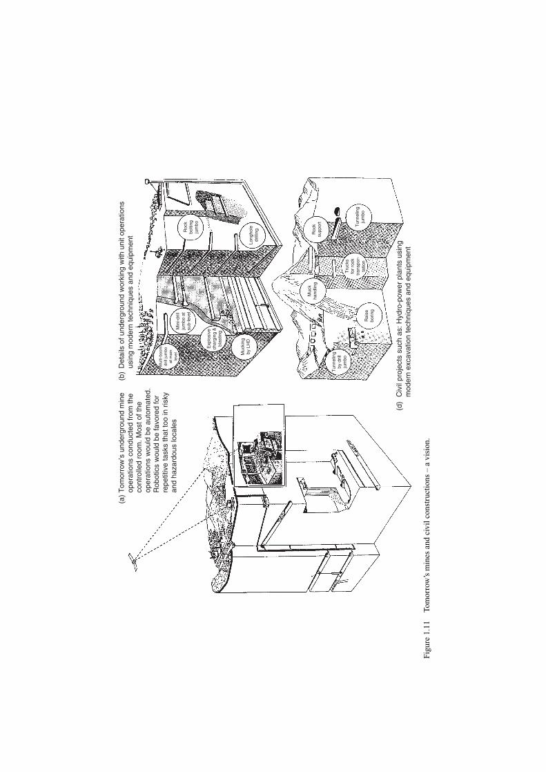
(a)
Tom
orro
w’s
und
ergr
ound
min
e
oper
atio
ns c
ondu
cted
from
the
co
ntro
lled
room
. Mos
t of t
he
oper
atio
ns w
ould
be
auto
mat
ed.
R
obot
ics
wou
ld b
e fa
vore
d fo
r
repe
titiv
e ta
sks
that
too
in r
isky
an
d ha
zard
ous
loca
les
(b)
Det
ails
of u
nder
grou
nd w
orki
ng w
ith u
nit o
pera
tions
us
ing
mod
ern
tech
niqu
es a
nd e
quip
men
t
Mul
ti-bo
omdr
ill ju
mbo
at m
ain
leve
lM
ini-d
rill
jum
bo a
tsu
b-le
vel
Exp
losi
vech
argi
ng &
blas
ting
Muc
king
by L
HD
Tun
nelin
gby
dril
lju
mbo
Muc
kha
ndlin
g
Rai
sebo
ring
(d)
Civ
il pr
ojec
ts s
uch
as: H
ydro
-pow
er p
lant
s us
ing
m
oder
n ex
cava
tion
tech
niqu
es a
nd e
quip
men
t
Tru
cks
for
rock
tran
spor
-ta
tion
Roc
ksu
ppor
t
Tun
nelin
gju
mbo
Long
hole
drill
ingRoc
kbo
lting
jum
bo
Figu
re 1
.11
Tom
orro
w’s
min
es a
nd c
ivil
cons
truc
tions
– a
vis
ion.
measurements and monitoring would play an important role. Sensors installed atstrategic locations would help to monitor mine atmosphere. There will be thoroughtechnology transfer from one field of engineering to another, for example, hydraulicfracturing is the concept used in oil fields for better oil recovery is now getting appli-cation to induce block caving in mines. Remote control would lead to more and moreautomation, and that in turn, would require more and more use of robotics.
REFERENCES
1. Ahaness, J.K. et al.: In-situ mining of hard rocks. In: Hartman (edt.): SME MiningEngineering Handbook. SMME, Colorado, pp. 1515–16.
2. Atlas Copco manual, 4th edition, 1982.3. Cruickshank, M.J.: Marine Mining. In: Hartman (edt.): SME Mining Engineering
Handbook. SMME, Colorado, pp. 2000, 2007.4. Dobrymin, A.: Gold mining in Russia. Mining Magazine, July, 2002, pp. 26.5. Franklin, J.A. and Dusseault, M.B.: Rock Engineering. McGraw-Hill, New York, 1989,
pp. 484.6. Grant, B.F.: Retorting oil shale underground: problems and possibilities. Quart. Colorado
School of Mines, 1964, vol. 59, pp. 40.7. Grim, E.C. and Hill, R.D.: Environmental protection of surface mining coal. US
Environment Protection Agency, Cincinnati, Ohio, 1974, EPA-67012-74-093.8. Hartman, H.L.: Introductory Mining Engineering. Johan Wiley & Sons, New York, 1987,
pp. 527.9. Lacy, W.C. and Lacy, J.C.: History of mining. In: Hartman (edt.): SME Mining
Engineering Handbook. SMME, Colorado, pp. 5–10.10. Lineberry, G.T. and Paolini, A.P.: equipment selection and sizing. In: Hartman (edt.): SME
Mining Engineering Handbook. SMME, Colorado, pp. 1551–55.11. Marsden, R.W. and Lucas, J.R.: Specialized underground extraction systems. In: Cummins &
Given (eds.): SME Mining Engineering Handbook. AIME, New York, 1973, pp. 21: 21–103.12. Meade, L.P.: Dimension stone: Friendsville quarry. In: Hartman (edt.): SME Mining
Engineering Handbook. SMME, Colorado, pp. 1401–02.13. Mineral Information Institute (MII), Web site, Denver, Colorado, 2001.14. Monesees, J.E. and Hansmire, W.H.: Civil works tunnels for vehicles, water and waste-
water. In: Hartman (edt.): SME Mining Engineering Handbook. SMME, Colorado, pp. 2124.
15. Olofsson, S.: Applied Explosives Technology for Construction and Mining. Applex,Sweden, 1997, pp. 160–170.
16. Sandstrom, G.E.: The history of tunneling. Barrier and Rockliff, London, 1963, pp. 427.17. Shepherd, R.: Ancient Mining. Elsevier Applied Science for IMM, London, 1993,
pp. 20–22.18. Sinha, R.S.: Introduction. In: R.S. Sinha (edt.): Underground Structures. Elsevier, New
York, 1989, pp. 20–21.19. Stefanko, R. and Bise, C.J.: Coal mining technology: Theory and practice. SME-AIME,
New York, 1983.20. Tamrock: Underground drilling and loading handbook, Tuula Puhakka (edtr.), 1997,
pp. 44.21. Treuhaft, M.B.: examples of current surface mining research: operational and potential.
Mining Engineering, 1984, vol. 36, no. 1, pp. 53–63.22. Whittaker, B.N. and Frith, R.C.: Tunneling – Design, Stability and Construction. IMM
Publication; 1990, pp. 1–17.
INTRODUCTION 17

References
1 Chapter 1. Introduction
1. Ahaness, J.K. et al.: In-situ mining of hard rocks. In:Hartman (edt.): SME Mining Engineering Handbook. SMME,Colorado, pp. 1515–16.
2. Atlas Copco manual, 4th edition, 1982.
3. Cruickshank, M.J.: Marine Mining. In: Hartman (edt.):SME Mining Engineering Handbook. SMME, Colorado, pp. 2000,2007.
4. Dobrymin, A.: Gold mining in Russia. Mining Magazine,July, 2002, pp. 26.
5. Franklin, J.A. and Dusseault, M.B.: Rock Engineering.McGraw-Hill, New York, 1989, pp. 484.
6. Grant, B.F.: Retorting oil shale underground: problemsand possibilities. Quart. Colorado School of Mines, 1964,vol. 59, pp. 40.
7. Grim, E.C. and Hill, R.D.: Environmental protection ofsurface mining coal. US Environment Protection Agency,Cincinnati, Ohio, 1974, EPA-67012-74-093.
8. Hartman, H.L.: Introductory Mining Engineering. JohanWiley & Sons, New York, 1987, pp. 527.
9. Lacy, W.C. and Lacy, J.C.: History of mining. In:Hartman (edt.): SME Mining Engineering Handbook. SMME,Colorado, pp. 5–10.
10. Lineberry, G.T. and Paolini, A.P.: equipment selectionand sizing. In: Hartman (edt.): SME Mining EngineeringHandbook. SMME, Colorado, pp. 1551–55.
11. Marsden, R.W. and Lucas, J.R.: Specialized undergroundextraction systems. In: Cummins & Given (eds.): SME MiningEngineering Handbook. AIME, New York, 1973, pp. 21: 21–103.
12. Meade, L.P.: Dimension stone: Friendsville quarry. In:Hartman (edt.): SME Mining Engineering Handbook. SMME,Colorado, pp. 1401–02.
13. Mineral Information Institute (MII), Web site, Denver,Colorado, 2001.
14. Monesees, J.E. and Hansmire, W.H.: Civil works tunnelsfor vehicles, water and wastewater. In: Hartman (edt.): SMEMining Engineering Handbook. SMME, Colorado, pp. 2124.
15. Olofsson, S.: Applied Explosives Technology forConstruction and Mining. Applex, Sweden, 1997, pp. 160–170.
16. Sandstrom, G.E.: The history of tunneling. Barrier andRockliff, London, 1963, pp. 427.
17. Shepherd, R.: Ancient Mining. Elsevier Applied Sciencefor IMM, London, 1993, pp. 20–22.
18. Sinha, R.S.: Introduction. In: R.S. Sinha (edt.):Underground Structures. Elsevier, New York, 1989, pp.20–21.
19. Stefanko, R. and Bise, C.J.: Coal mining technology:Theory and practice. SME-AIME, New York, 1983.
20. Tamrock: Underground drilling and loading handbook,Tuula Puhakka (edtr.), 1997, pp. 44.
21. Treuhaft, M.B.: examples of current surface miningresearch: operational and potential. Mining Engineering,1984, vol. 36, no. 1, pp. 53–63.
22. Whittaker, B.N. and Frith, R.C.: Tunneling – Design,Stability and Construction. IMM Publication; 1990, pp.1–17.
2 Chapter 2. Rocks and minerals
1. Blyth, F.G.H. and Freitas, M.H.: Geology for Engineers.ELBS, 1988, pp. 254.
2. Boky, B.: Mining. Mir Publishers, Moscow, 1988, pp.11–17.
3. Dearman, W.R.: The charactrization of rocks in civilengineering practice in Britain. Proc. Colloq. Geologie del’Ingnieur, Belgium, 1974, pp. 1–75.
4. Franklin, J.A. and Dusseault, M.B.: Rock Engineering.McGraw-Hill, New York, 1989, pp. 14–46.
5. Hudson, J.A. and Harrison, J.P.: Engineering RockMechanics. Pergamon, 1997, pp. 116.
6. ISRM: ISRM Commission on classification of rocks androck masses, M. Rocha, Coordinator, Int. J. Rock Mech. Mi.Sc. Geomech. Abstr. 18(1), 1981(a), pp. 85–110.
7. Jimeno, C.L; Jimeno, E.L. and Carcedo, F.J.A.: Drillingand Blasting of Rocks. Balkema, A.A., Netherlands, 1995,pp. 30–35.
8. Lewis, R.S. and Clark, G.B.: Elements of Mining. 3rd ed;Wiley, New York, 1964, pp. 7–10.
9. Matti, H.: Rock Excavation Handbook. Sandvik – Tamrock,1999, pp. 12–52.
10. Mineral Information Institute (MII), 2001. Denver,Colorado, Web site.
11. Panek, l.A.: Stresses About Mine Openings in aHomogeneous Rock Body. Edward Bros. Ann Arbor, 1951, pp.50.
12. Peele, R.: Mining Engineering Handbook, 3rd ed; Wiley,New York, 1941, pp. 1:15–49, 2:18–28.
13. Taylor, H.K. General background theory of cutoff grade.Trans. Inst. Min. Metal. London (Section A mineralIndustry), 1972, pp. A160–79.
14. Whittaker, B.N. and Frith, R.C.: Tunnelling – Design,Stability and Construction. IMM Publication; 1990, pp.19–51.
3 Chapter 3. Prospecting, exploration &site investigations
1. Agoshkov, M; Borisov, S. and Boyarsky, V.: Mining ofOres and Non-metallic Minerals. Mir Publishers, Moscow,1988, pp. 14
2. Atlas Copco Manual, 4th edition, 1982, pp. 229–35,292–302.
3. Bailly, P.A. and Still, A.R.: Exploration for mineraldeposits. In: Cummins & Given (eds.): SME MiningEngineering Handbook. AIME, New York, 1973, pp. 5: 2–9.
4. Barton, N; Lien, R. and Lunde, J.: Engineeringclassification of rock masses for design of tunnel support.Rock mechanics, vol. 6, no. 4, 1974, pp. 183–236.
5. Bieniawski, Z.T.: Ground control. In: SME MiningEngineering Handbook, Hartman (edt.). SMME, Colorado, 1992,pp. 897–911.
6. Bieniawski, Z.T.: Rock mechanics design in mining andtunneling. A.A. Balkema, 1984, pp. 97–132.
7. Boky, B.: Mining. Mir Publishers, Moscow, 1967, pp.11–27.
8. Bruce, Charles.: Orebody evaluation. In: UndergroundMining Methods Handbook, W.A. Hustrulid (edt.), SME-AIME,New York, 1982, pp. 3–4, 40–43.
9. Coats, D.F.: Classification of rocks for rock mechanics.International journal of rock mechanics & mining science,vol.1, 1964, pp. 421–29.
10. Deere, D.U.: Technical description of rock cores forengineering purposes. Rock mechanics and engineeringgeology, vol.1, no.1, 1964, pp. 17–22.
11. Hartman, H.L.: Introductory Mining Engineering. JohnWiley & Sons, New York, 1987, pp. 40–61.
12. Matti, H.: Rock Excavation Handbook. Sandvik – Tamrock,1999, pp. 20–52.
13. Nilsen, Bjorn and Ozdemir, Levent.: Recent developmentin site investigations and testing for hard TBM projects.In: Proc. RETC, AIME, 1999, pp. 715–31.

14. Rogers, G.R.: Geophysical surveys. In: Cummins & Given(eds.): SME Mining Engineering Handbook. AIME, New York,1973, pp. 5: 2–5, 24–34.
15. Whittaker, B.N. and Frith, R.C.: Tunnelling – Design,Stability and Construction. IMM Publication; 1990, pp.19–35.
4 Chapter 4. Drilling
1. Atlas Copco manual, 4th edition, 1982 and Atlas CopcoLeaflets.
2. Hartman, H.L.: Introductory Mining Engineering. JohnWiley & Sons, New York, 1987, pp. 117–18.
3. Henry, H.R.: Percussive Drill Jumbos. In: W.A. Hustrulid(ed.): Underground Mining Method Handbook. SME (AIMMPE),New York, 1982, pp. 1034–40.
4. Jimeno, C.L; Jimenó, E.L. and Carcedo, F.J.A.: Drillingand Blasting of Rocks. A.A. Balkema, Netherlands, 1997, pp.8–47.
5. Kurt, E.H.: Primary Breaking. In: W.A. Hustrulid (ed.):Underground Mining Method Handbook. SME (AIMMPE), New York,1982, pp. 999–1005.
6. Rzhevsky, V.V.: Opencast Mining Unit Operations. MirPublishers, Moscow, 1985, pp. 117.
7. Sandvik – Tamock: Drills and drilling accessories –Leaflets and literature.
5 Chapter 5. Explosives and blasting
1. Agoshkov, M; Borisov, S. and Boyarsky, V.: Mining ofOres and Non-metallic Minerals. Mir Publishers, Moscow,1988, pp. 80, 96.
2. Atlas Copco – Secondary breaking; Leaflets.
3. Bauer, A. and Crosby W.A.: Blasting. In: B.A. Kennedy(edt.): Surface Mining. SMME, Colorado, 1990, pp. 548
4. Champion, M.M.: Explosive loading equipment. In:Underground Mining Methods Handbook, W.A. Hustrulid (edt.).SME-AIME, New York, 1982, pp. 1084–1091.
5. Clark, G.B.: Explosives. In: Surface Mining, E.P.Pfleider (edt.), AIME, New York, 1964, pp. 341–354.
6. Crowl, D.A. and Louvar, J.F.: Chemical process safety.Prentice Hall PTR, New Jersey, 2002, pp. 253–254.
7. Dowding, C.H. and Aimone, C.T.: Rock breakage andexplosives. In: Hartman (edt.): SME Mining EngineeringHandbook. SMME, Colorado, pp. 722–735.
8. Ganpathy, B.: Advance course on rock blasting, IDL,Hydrabad, India, Nov. 1978.
9. Goddoy S.G. and Viera M.D.: Computerized model fordesign optimization blasting pattern in tunnels.Tunneling’82, IMM Publication; Editor Michael J.J. Jones.
10. Gregory, C.E.: Explosives for North American Engineers.Trans. Tech. Publ. Rockport, M.A., 1979, pp. 303.
11. Hartman, H.L.: Introductory Mining Engineering. JohnWiley & Sons, New York, 1987, pp. 125–133.
12. Jimeno, C.L; Jimeno, E.L. and Carcedo, F.J.A.: Drillingand Blasting of Rocks. A.A. Balkema, Netherlands, 1997,pp. 98–130.
13. Matti, H.: Rock Excavation Handbook. Sandvik – Tamrock,1999, pp. 100–121.
14. Pradhan, G.K.: Explosives and Blasting Techniques.Mintech Publications, Buuvenswar, 1996, pp. 5–10, 53–80,240–242.
15. Sarapuu, Erich.: Electro energetic rock breaking

systems. Mining Congress Jou. Vol. 59, 1973.
16. Sundram, S.S. and Singh, B.: Blasting and itsunderground applications. Technical renovations – KhetriCopper Complex, 1978, pp. 1–15.
17. Tatiya, R.R.: Current practices of secondary breakingin underground metalliferous mines in India and abroad.National Symp. on mechanics of mining ground, BHU, 1982,pp. 129–136.
6 Chapter 6. Mucking, casting andexcavation
1. Atlas Copco manual, 4th edition, 1982.
2. Brealey, S.C; Belley, J. and Rickus, J.E.: Mineralquality determination and control in stratified deposits.IMM’s International Symposium on Surface mining andQuarrying, Bristol, England, 4–6 Oct. 1983, pp. 153–157.Input: Select equipment those are suitable for comparison.Task: Screening based on: Excavation’s locale and itsgeometry (size, shape, slope, etc.). Equipments demand forventilation, fragmentation, road-conditions, muck pile,illumination etc. Likely or rated output as supplied by themanufacturers. Output: Equipment technically and SEEsuitable. Task: Economic calculations, and determining unitproduction cost by considering costs such as: Capital,Energy, Maintenance, development, wages etc. Equipmentselection: Select the one which further match with thelayout, production requirements, and other sets ofequipment that would be available to complete theproduction cycle. Sometimes those equipment graded highestmay not be the final choice.
Failed: Technically not suitable Output: selectingequipment as per the technical needs. Input: Equipmentfound technically suitable Task: Screening for Safety,Ergonomic & Environment (SEE) suitability: Safety -Inherent safety features, Danger of falling rock/ground,Danger to third party etc. Ergonomical – Ease of operation,comforts and liking by the crew. Environment – Generationof Noise, Heat, Fumes, Vibrations, Noxious gases, Dustsetc. Output: Equipment grading with respect to theiroverall production cost together with other considerations.
Failed: On account of Environment, Safety & Ergonomicsreasons
Figure 6.12 A flow-chart to select an equipment.
3. Caterpillar Performance Handbook, 2000; Excavators;Wheel loaders; Backhoes.
4. Chadwick, J.: The largest hydraulic excavator O & K.Mining Magazine, 1999.
5. Dangler: Mucking equipment in sinking. In: W.A.Hustrulid (edt.): Underground Mining Methods Handbook,SME-AIME, New York, 1982, pp. 1263–1265.
6. Files, T.I.: Hydraulic excavators. In: B.A. Kennedy(edt.): Surface Mining. SMME, Colorado, 1990, pp. 1635.
7. GHH leaf lets and websites.
8. Hartman, H.L.: Introductory Mining Engineering. JohnWiley & Sons, New York, 1987, pp. 134–140.
9. Johnstone, H.A.: Trends in trackless mining. MiningMagazine, Jan. 1975.
10. Kahle, M.B. and Mosele, C.A.: Development of miningmethods in Gulf Coast Lignite. Mining Engg. Vol. 35, 1983,pp. 1163–66.
11. Knopp, R.A.: Concept in LHD design. Mining Magazine,Jan. 1975.
12. Krupp – Websites, 2000.
13. Modular mining systems, 1998, leaflets.
14. Nautilus International Control & Engineering, 1998.Leaflets.
15. Page and Marion, leaflets.
16. Pokrovsky, N.M.: Driving horizontal workings andtunnels. Mir Publishers, Moscow, 1988, pp. 69, 295.
17. Shevyakov, L.: Mining of mineral deposits. Foreignlanguage publishing house, Moscow, 1988, pp. 616–627.
18. Sinha, R.S.: Introduction. In: R.S. Sinha (edt.):Underground Structures. Elsevier, New York, 1989, pp.20–21.
19. Tatiya, R.R.: Use of LHD in underground metalliferousmines. Jour. of Institution of Engineers, Vol. 62, 1981,pp. 70–73.
20. Toro tele remote controlled LHD system. Leaflets.
21. Weimer, W.H. and Weimer, W.A.: Surface coal mines. In:Cummins and Given (eds.): SME Mining Engineering Handbook,AIME, New York, 1973, pp. 17–129, 130.
7 Chapter 7. Transportation – haulage andhoisting
1. Atlas Copco, leaflets and literature.
2. Bise, C.J.: Mining engineering analysis, SME, Littleton,Co, 1986. pp. 120–30.
3. Brantner, J.W.: Mine haulage locomotive calculations.In: Cummins and Given (eds.): SME Mining EngineeringHandbook. AIME, New York, 1973, pp. 14:17–18.
4. Brucker, D.S.: Faster and deeper – The sign of the timesin hoisting, Rept. ASEA, Swedish Trade Commision,LosAngeles, 1975, pp. 29.
5. Buckeridge, R.M; Carey, W.T. et al.: Rail haulagesystem. In: Underground Mining Methods Handbook. W.A.Hustrulid (edt.), SME-AIME, New York, 1982, pp. 1227–45.
6. Caterpillar – Performance handbook, 2000. pp. 10:22–26.Monorail support beams (b) End dump car (d) Sectionthrough a dump yard (Swedish arrangement for dumpingbottom-discharge cars). (c) Gable bottom discharge car(a) Rocker/side discharge car Support wheel for carbottom while unloading Monorail beam Ore car O r e p a s s
Figure 7.15 Mine cars and their unloading arrangement.
7. Connel, J.P.: Truck Haulage. In: Cummins and Given(eds.): SME Mining Engineering Handbook. AIME, New York,1973, pp. 18: 16–22.
8. G.I.A. Industries, Sweden, leaflets.
9. Grosvenor, N.E.: Mine cars and track. In: Cummins andGiven (eds.): SME Mining Engineering Handbook. AIME, NewYork, 1973, pp. 14:3–7.
10. Harmon, J.H.: Hoists and hoisting systems. In: Cummins& Given (eds.): SME Mining Engineering Handbook. AIME, NewYork, 1973, pp. 15: 2–69.
11. Hartman, H.L.: Introductory Mining Engineering. JohnWiley & Sons, New York, 1987, pp. 317–31.
12. Karelin, N.T.: Mine Transport. Orient Longmans, Bombay,1967, pp. 15–37, 94–96.
13. Mann, C.D.: Swedish-type car dumps. In: Cummins & Given

(eds.): SME Mining Engineering Handbook. AIME, New York,1973, pp. 14: 41–43.
14. V. Borshch-Komponiets, A. Navitny and G. Knysh: Minesurveying. Mir Publishers, Moscow, 1985, pp. 196–210.
8 Chapter 8. Supports
1. Agoshkov, M.; Borisov, S. and Boyarsky,V.: Mining ofOres and Non-metallic Minerals. Mir Publishers, Moscow,1988, pp. 42–44. Displacement zones due to undergroundexcavations Ore body Ore body Displacement zone Dangerouszone Caving zone γ γ� γ° 3 2 1
Figure 8.9 Ground disturbance above the excavation areainfluencing the above lying strata right up to the surfacedatum.
2. American Concrete Institute, Shotcreting, publicationSP-14 Committee 506, Detroit, Michigan, 1996.
3. Auld, F.: Design of shaft lining. In: Proc. Inst. Civ.Eng; part 2, no. 67, 1979, London.
4. Biron, C. and Arioglu, E.: Design of supports in mines.John Wiley & Sons, 1983, pp. 89–101, 105–11, 126–29.
5. Boky, B.: Mining. Mir Publishers, Moscow, 1967, pp.300–309.
6. Chlumecky, N.: Artificial supports. In: Cummins andGiven (eds.): SME Mining Engineering Handbook. AIME, NewYork, 1973, pp. 13: 150–55.
7. Deshmukh, R.T.: Winning and working coal, 1965, pp.60–120.
8. Franklin, J.A. and Dusseault, M.B.: Rock Engineering.McGraw-Hill, New York, 1989, pp. 556.
9. Hadjigeorgious, J. and Charette, F.: Rock bolting forunderground excavations. In: Hustrulid and Bullock (eds.):SME Underground Mining Methods. Colorado, 2001, pp. 547.
9b. Hartman, H.L.: Introductory Mining Engineering. JohnWiley & Sons, New York, 1987, pp. 311–15.
10. Hudson, J.A. and Harrison, J.P.: Engineering RockMechanics. Pergamon, 1997, pp. 270–72, 284.
11. Holland, C.T. and, E.: Coal mines bumps: Some aspectsof occurrance, causes and control. Bull 35, 1954, USBM.
11b. Kaiser and Tannant, D.D.: The role of shotcrete inhard rock mines. In: Hustrulid and Bullock (eds.): SMEUnderground Mining Methods. Colorado, 2001, pp. 583.

12. Obert, L.; Duvall, W.L. and Merill, R.H.: Design ofunderground openings in competent ground rock. Bull 587,1960, USBM.
13. Panek, L.A. and McCormic, J.A.: Roof/Rock bolting. In:Cummins and Given (eds.): SME Mining Engineering Handbook.AIME, New York, 1973, pp. 13: 126.
14. Peng, S.S. and Chiang, H.S.: Longwall Mining. Wiley(Inter science), New York, 1984, pp. 708.
15. Saxena, N.C. and Singh, B.: Props in longwall workings,J. Mines, Metal & Fuels, 1969.
16. South African Chamber of mines, 1977, News Bulletin.
9 Chapter 9. Drives and tunnels(conventional methods)
1. Atlas Copco manual and leaflets.
2. Berta, G.: Explosives – An engineering tool.Italesplosivi, Milano, Italy, 1990.
3. Bieniawski, Z.T.: Ground control. In: SME MiningEngineering Handbook, Hartman (edt.). SMME, Colorado, 1992,pp. 897–911.
4. Bieniawski, Z.T.: Rock mechanics design in mining andtunneling. A.A. Balkema, 1984, pp. 97–132.
5. British Steel: Common yielding steel supportconfigurations for tunnels and roadways.
6. Chironis, N.P.: Shooting coal pay off. Coal Age, vol.88, No. 9, 1983, pp. 86–91.
7. Deere, D.U et al.: Design of tunnel support systems.Highway Research Record, no. 339, 1970, pp. 26–33.
8. Douglas, T.H. and Arthur, L.J.: A guide to the use ofrock reinforcement in underground excavations, CIRA ReportNo. 101, 1983, pp. 74.
9. Gregory, C.E.: Explosives for North American Engineers.Trans. Tech. Publ. Rockport, M.A., 1984, pp. 314.
10. Hoek, E. and Wood, D.: Rock support. World tunneling,No. 2, 1989, pp. 131–136.
11. IEL Ltd. Explosive division. Leaflets and literature.
12. Jimeno, C.L.: Jimeno, E.L. and Carcedo, F.J.A.:Drilling and Blasting of Rock A.A.Balkema, Netherlands,1997, pp. 217–225.
13. Langefors, U.: Fragmentation in rock blasting. Mine andMineral Engg. 1966, Vol. 2, No. 9, pp. 339.
14. Matti, H.: Rock excavation handbook. Sandvik – Tamrock,1999, pp. 214–233.; and Tamrock leaflets and literature.
15. Olofsson, S.: Applied Explosives Technology forConstruction and Mining. Applex, Sweden, 1997, pp. 131–155,180.
16. Pokrovsky, N.M.: Driving horizontal workings andtunnels. Mir Publishers, Moscow, 1988, pp. 12–36, 66,105–106, 268–273, 291.
17. Pradhan, G.K.: Explosives and Blasting Techniques.Mintech Publications, Buuvenswar, 1996, pp. 214, 368.
18. Roger, H.: Blasting. In: W.A. Hustrulid (edt.),Underground Mining Methods Handbook. SME-AIME, New York,1982, pp.1581–86.
19. Vergne, J.N.: Hard Rock Miner’s Handbook. McIntoshRedpath Engineering, 2000, pp. 236.
20. Whittaker, B.N. and Frith, R.C.: Tunneling – Design,Stability and Construction. IMM Publication; 1990, pp. 3–5,270–80.
21. Wilber, L.D.: Rock tunnels. In: J.O. Bichel and T.R.Kuesel (edts.): Tunnel Engineering Handbook.VanNostrand-Reinhold, New York, 1982, pp. 123–207.
10 Chapter 10. Tunneling by roadheadersand impact hammers
1. Friant, James, E. and Ozdemir, Levent.: Tunnel boringtechnology – present and future. In: Proc. RETC, AIME,1993, pp. 869–88.
2. Handwith, H.J. and Dahmen, N.J.: Tunnelling machines.In: Underground Mining Methods Handbook, W.A. Hustrulid(edt.) SME-AIME, New York, 1982, pp. 1107–10.
3. Kogelmann, W.J. and Schenck, G.K.: Recent North Americanadvances in boom-type tunneling machines. In: Tunneling’82,IMM Publication, Michael, J.J. Jones (Edt.), 1982, pp.205–210.
4. Kogelmann, W.J.: Roadheader application and selectioncriteria; Alpine Equip. Corpo. State College, PA, 1988.
5. Matti, H.: Rock excavation Handbook. Sandvik – Tamrock,1999, pp. 254–272. Excavation with short advanced roofsection using Roadheader (AMT70)
Figure 10.11 Application of roadheader AMT 70 with NATM.
6. McFeat Smith, I. and Fowell, R.J.: The selection andapplication of roadheaders for rock tunneling. In: Proc.RETC, AIME, Atlanta, 1979, pp. 261–79.
7. Morris, A.H.: Practical results of cutting harder rockswith picks in United Kingdom coal mine tunnels. In:Tunneling’85, IMM, M.J. Jones (Edt.), 1985, pp. 173–77.
8. Paurat – leaf lets.
9. Pokrovsky, N.M.: Driving horizontal workings andtunnels. Mir Publishers, Moscow, 1988, pp. 239.
10. Randy, F; George, H.K. and Ignacy Puszkiewicz, Twofirsts in tunneling in Canada: Proc. RETC, AIME, 1993, pp.273–93.
11. Sandtner, A. and Gehring, K.H.: Development ofroadheading equipment for tunneling by NATM. In:Tunneling’88, IMM Publication, 1988, pp. 275–88.
12. Singh, J.: Heavy Constructions – Planning, Equipmentand Methods. Oxford & IBH Pub. New Delhi, 1993, pp. 531.
13. Whittaker, B.N. and Frith, R.C.: Tunneling – Design,

Stability and Construction. IMM Publication; 1990. pp.141–45.
11 Chapter 11. Full-face tunnel borers(TBMs) & specialmethods
1. Babenderede, S.: Application of NATM for metroconstruction in the FRG, Euro-tunnel 80, IMM, London, 1980,pp. 54–58.
2. Bieniawski, Z.T.: Rock mechanics design in mining andtunneling. A.A. Balkema, 1984, pp. 272.
3. Breeds, C.D. and Conway, J.J.: Rapid excavation. In: SMEMining Engineering Handbook, Hartman (edt.). SMME,Colorado, pp. 1871–78, 1905–07.
4. Cazenave, B. and Le Goer, Y.: Mechanical precutting.North American Tunneling, 1996.
5. Deacon, W.G. and Hughes, J.F.: Application of NATM atBarrow-upon-Soar gypsum mine to construct two surfacedrifts. In: Tunneling ’88 IMM Publication, 1988, pp. 69–77.
6. Dias Daniel and Kastner, R.: Effects of pre-lining ontunnel design. In: Underground construction in moderninfrastructure, Franzen, Bergdahl and Nordmark (Eds). A.A.Balkema, 1998, pp. 391–397.
7. Franklin, J.A. and Dusseault, M.B.: Rock Engineering.McGraw-Hill, New York, 1989, pp. 563–85.
8. Friant, James. E. and Ozdemir, Levent.: Tunnel boringtechnology – present and future. In: Proc. RETC, AIME,1993, pp. 869–888.
9. Graham, P.C.: Rock exploration for machinemanufacturers. In: Proce. Sympo. on Exploration for rockengineering, Johannesburg, 1976, pp. 173–180.
10. Guilloux A.: French national report on tunneling insoft ground. In: Underground construction in soft ground,Fujita and Kusakabe (Eds). A.A. Balkema, 1995, pp. 97–100.
11. Hack, A.: TBM Tunneling, Hagenberg/Austria. Proceedingsof International Lecture Series 5, 1996.
12. Hamburger, Harmann and Weber, Walter.: Tunnel boring oflarge cross sections with full face and enlarging machinesin hard rock. In: Proc. RETC, AIME, 1993, pp. 811–831.
13. Handwith, H.J. and Dahmen, N.J.: Tunnelling machines.In: Underground Mining Methods Handbook, W.A. Hustrulid
(edt.). SME-AIME, New York, 1982, pp. 1107–10.
14. Hartman, H.L.: Introductory Mining Engineering. JohnWiley & Sons, New York, 1987, Tunneling – pp. 498–503.
15. Heflin, L.H. and Irshad, Mohammad.: Soft ground NATMtunnel design. In: Proc. RETC, AIME, 1987, pp. 112–129.
16. Herrenknecht GmbH, Schwanau, Germany: Literature andleaflets.
17. Herrenknecht, M. and W. Burger.: The new generations ofsoft ground tunneling machines. Proc. RETC 1999, AIME,647–662.
18. Johnson, G.D.: Thorough grouting can reduce liningcosts in tunnels. In: Proc. Conf. Grouting in Geo-tech.Eng. Am. Soc. Civ. Eng; New York, 1982, pp. 892–906.
19. Johnson, S.J.: Cement and clay grouting of foundations;Grouting with clay-cement grouts. J. Soil Mech. and Found.Div. ASCE, 1958, paper 1545, pp. 1–12.
20. Kurihara, K. Kawata, H. and Konishi, J.: Currentpractices of shield tunneling methods – A survey onJapanese shield tunneling. In: Underground construction insoft ground. Fujita and Kusakabe (Eds). A.A. Balkema, 1995,pp. 329–336.
20b. LTM Corporation, Seoul, Korea – Leaflets andliterature (soft and hard copies).
21. Lislerud, A.: Hard rock tunnel boring – prognosis andcosts. In: Tunneling and underground space technology,1988, vol. 3, pp. 1, 9–17.
22. Lislerud, A. et al.: Hard rock tunnel boring.Norwaegian Institute of Technology, Engineering projectreport 1–83, 1983, pp. 159.
23. Maidl, B. Herrenknecht, M. and Anheuser, L.: MechanisedShield Tunneling. Ernst & Sohn, Berlin, 1996, pp. 4, 35–36,275–277.
24. Martin, Herrenknecht Ing. E.h. and Burger, Werner.: Thenew generations of soft ground tunneling machines. In:Proc. RETC, AIME, 1999, pp. 647–662.
25. Megaw, T.M. and Bartlett, J.V.: Tunnels: Planning,Design, Construction. Ellis Horwood Limited, Chichestre,
1983, Cut and Cover: pp. 11–19.
26. Nilsen, B. and Ozdemir, L.: Recent development in siteinvestigations and testing for hard TBM projects; Proc.RETC, AIME, 1999, pp. 715–731.
27. Parkes, D.B.: The performance of tunnel boring machinesin rock. In: CIRIA Special Publication no. 62, 1988, pp.56.
28. Pokrovsky, N.M.: Driving horizontal workings andtunnels. Mir Publishers, Moscow, 1988, pp. 328–332,348–350.
29. Randy, Fulton. Geogrge, H.K. and Ignacy, Puszkiewicz.:Two firsts in tunneling in Canada. In: Proc. RETC, AIME,1993, pp. 273–293.
30. Robbins TBMs, Robbins Company, Kent, USA.: Literatureand leaflets.
31. Sandtner, A. and Gehring, K.H.: Development ofroadheading equipment for tunneling by NATM. Tunneling ’88,IMM Pub. pp. 275–288.
32. Sauer, G. and Gold, H.: NATM ground support conceptsand their effect on contracting practices. In: RETC Proc.1989, pp. 67–86.
33. Sauer, G.: When an invention is some thing new: frompractice to theory in tunneling, Trans. IMM, London, No.97, 1988 , pp. A94–108. Tab. 15.1.
34. Singh, J.: Heavy Constructions – Planning, Equipmentand Methods. Oxford & Ibh Pub. New Delhi, 1993, pp. 528.
35. Stevenson Garry, W:. Empirical estimates of TBMperformance in hard rock; Proc. RETC, AIME, 1999, pp.993–1006.
36. Thon, J.G.: Tunnel boring machines. In: Tunnelengineering handbook, J.O. Bickel and T.R. Kuesel (Eds),1983, pp. 670.
37. Toolanen, B. Hatwig, S. and Janzon, H.: Designconsiderations for large hard rocks TBMs when used in badground. In: Proc. RETC, AIME, 1993, pp. 853–868.
38. Whittaker, B.N. and Frith, R.C.: Tunneling – Design,Stability and Construction. IMM Publication; 1990, pp.

69–91, 199–227, 351–360.
39. Writh’s TBMs, Wirth Company, Erkelenz, Germany:Literature and leaflets.
12 Chapter 12. Planning
1. Agoshkov, M; Borisov, S. and Boyarsky,V.: Mining of Oresand Non-metallic Minerals. Mir Publishers, Moscow, 1988,pp. 13–14, 33–35, 45–55, 63–68, 245.
2. Boky, B.: Mining. Mir Publishers, Moscow, 1988, pp.254–58, 338–49.
3. Desmukh, R.T. and Deshmukh, D. J.: Winning and workingcoal. Mitra Press, Calcutta, 1967, pp. 236–269.
4. Dowis, J.E.: Detailed cost estimating for a miningventure. In: Mining Industry Costs, J.R. Hoskin (edt.).Northwest Mining Asso. Spokane, W.A. 1982, pp. 193–212.
5. Folinsbee, J.C. and Clarke, R.W.: In: Design andoperation of caving and sublevel stoping mines, D.R.Steward(edt.). SME-AIME, New York, 1981, pp. 55–65.
5b. Fritzsche, C.H. and Potis E.L.J.: horizon mining.George Allen & Unwin Ltd., London, 1954, pp. 510–515.
6. Hartman, H.L.: Introductory Mining Engineering. JohanWiley & Sons, New York, 1987, pp. 288–98.
7. Lane, K.F. Choosing the optimum cutoff grade. ColoradoSchool of Mines Quarterly, 59, 1964, No. 4.
8. Lane, K.F. Commercial aspects of choosing cutoff grades,16th APCOM Symposium, 1979, 280–5.
9. Shevyakov, L.: Mining of Mineral Deposits. ForeignLanguage Publishing House, Moscow, 1988, pp. 109–144.
10. Tatiya, R.R. PhD Thesis, Imperial College of Scienceand Technology, London University, 1987, London.
11. Taylor, H.K. General background theory of cutoff grade.Trans. Inst. Min. Metal. London (Section A: MineralIndustry), 1972, A160-79.
12. Taylor, H.K. cutoff grades – some further reflections,Trans. Inst. Min. Metal. London (Section A: Mineral Indst),1985, A204-16.
13. Vorobjev, B.M. and Deshmukh, R.T.: Advanced coalmining. Mitra Press, Calcutta, 1964, pp. 83–193.
13 Chapter 13. Excavations in upwarddirection – raising
1. Agoshkov, M; Borisov, S. and Boyarsky,V.: Mining of Oresand Non-metallic Minerals. Mir Publishers, Moscow, 1988,pp. 67–69.
2. Alimak: Raise Climber (leaflets). Vein Mining, 1977.
3. Atlas Copco – Robbins: Leaflets and website, 2002.
4. Atlas Copco: Raise driving with Jora Hoist, 1970.
5. David, J.S. and Pfleider, E.P.: Ore-pass, Tunnels andshafts. In: Surface Mining, E.P. Pfleider (edt.)AIME, NewYork, 1964, pp. 637–642.
6. Hamrin, H.: Guide to Underground Mining Methods andApplication. Atlas Copco, Sweden, 2002, pp. 12–13.
7. Home, L.W.: Raise Drills. In: Underground Mining MethodHandbook, W.A. Hustrulid (edt.). SME (AIMMPE), New York,1982, pp. 1093–1097.
8. Jimeno, C.L; Jimeno, E.L. and Carcedo, F.J.A.: Blastingand Drilling of Rocks. A.A. Balkema, Netherlands, 1997,pp. 241.
9. Kolihan Copper Mine, India.: Technical Innovations –Long-hole Blasting, 1986.
10. Olofsson, S.: Applied Explosives Technology forConstruction and Mining. Applex, Sweden, 1997, pp. 160–170.
11. Paul, R.B. and Eric, G.B.: Drifting and Raising byRotary Drilling. In: Cummins & Given (eds): SME MiningEngineering Handbook. AIME, New York, 1973, pp. 10: 89–97.
12. Selleck, D.J. and Pfleider, E.P.: Ore passes, Tunnelsand Shafts. In: Surface Mining, Vol. II, 1994, pp. 6:38–40.
13. Singh, J.: Heavy Constructions – Planning, Equipmentand Methods. Oxford & Ibh Pub. New Delhi, 1993, pp.554–560.
14. Svensson, H.: Rasie Climbers. In: Underground MiningMethod Handbook, W.A. Hustrulid (edt.). SME (AIMMPE), NewYork, 1982, pp. 1051–1055.

15. Tatiya, R.R.: Longhole Raising, Mining and EngineeringJournal Vol. 18, 1979, pp. 1–8.
16. Vergne, J.N.: Hard Rock Miner’s Handbook. McIntoshRedpath Engineering, 2000, pp. 324–329.
14 Chapter 14. Shaft sinking
1. Beus, M.J.: An approach to field testing and design fordeep mine shafts in Western USA. Shaft EngineeringConference, 1989, IMM, London, pp. 53–55.
2. Boky, B.: Mining. Mir Publishers, Moscow, 1988, pp.228–42.
3. Breeds, C.D. and Conway, J.J.: Rapid excavation. In:Hartman (edt.): SME Mining Engineering Handbook, SMME,Colorado, 1992, pp. 1883–85.
3b. Bruce A, Mckinstry.: Sinking the Silver Shaft. Proc.RETC, AIME, 1983, pp. 103–25. (www.smenet.org)
4. Douglas Alastair A.B. and Pfutzenreuter, Fred R.B.:Overview of current South African vertical circular shaftconstruction practice. Shaft Engineering Conference, 1989,IMM, London, pp. 137–54.
5. Falter, B.: Stability of liners in shaft design. ShaftEngineering Conference, 1989, IMM, London, pp. 169–70.
6. Franklin, J.A. and Dusseault, M.B.: Rock Engineering.McGraw-Hill, New York, 1989, pp. 563–80.
7. Klein.: Shaft sinking by ground freezing in coal miningindustry in the Federal Republic of Germany. ShaftEngineering Conference, 1989, IMM, London, pp. 276–78.
8. Megaw, T.M. and Bartlett, J.V.: Tunnels: Planning,Design, Construction. Ellis Horwood Limited, Chichestre,1983, pp. 66–68, 117.
9. Nitro Nobel – Website, literature and leaflets.
10. Przygodzka, B.B. et al.: Extensometer investigations offrozen shaft lining. Shaft Engineering Conference, 1989,IMM, London, pp. 71.
11. Unrug, K.F.: Construction of development openings. In:Hartman (edt.): SME Mining Engineering Handbook. SMME,Colorado, 1992, pp. 1580–1620.
12. Vergne, J.N.: Hard Rock Miner’s Handbook. McIntoshRedpath Engineering, 2000, pp. 152.
15 Chapter 15. Large sub-surfaceexcavations
1. Aarvoll, M; et al.: Storage of industrial waste in largecaverns. Int. Symp. nn large rock caverns, 1986, vol. 1,pp. 759–70.
2. Anon.: Civil engineering guidelines for planning anddesigning. Hydro-electric developments. Vol. 3 Americalsociety of civil engineers, 1989a.
3. Azun, A.A., Chilingarian, G.V., Robertson, J.O. andKumar, S.: Surface operations in petroleum production, II.1989, Elsevier, New York, pp. 457–70.
4. Fidencio, M.: Aguampila underground power house complexexcavation sequence. Retc Pro. 1993, pp. 1047–65.
5. Goyal, K.L., Kumar, M. and Mittal, A.K.: Undergroundstorage of hydrocarbons. In: B. Singh (edt.). Int. symp.on Underground Engineering, 1988, Balkema, pp. 415–17.
6. Hector, A.N. and Guillermo, K.: Geotechnics forconstruction of chamber to house an underground crusher inCodelco – Chile’s EI Teniente mine. Tunneling’ 82, IMMPublication; Editor Michael J.J. Jones. pp. 49–62.
7. Hudson, J.A. and Harrison, J.P.: Engineering RockMechanics. Pergamon, 1997, pp. 288, 90.
8. Iyengar, M., Soni, A.S., Malkani, S., Sharam, A.K. andRamkrishna, K.S.: Proposed crude oil storage in undergroundrock caverns at Uran. In: B. Singh (edt.). Int. symp. onUnderground Engineering, 1988, Balkema, pp. 441–48.
9. Khot, A.S., Vaid, D.K., Chaphalkar, S.G. and Mokhashi,S.L.: stress distribution around machine hall cavity withspecial reference to Varahi underground power house. In:B. Singh (edt.). Int. symp. on Underground Engineering,1988, Balkema, pp. 419–23.
10. Kumar, P. and Singh, B.: On the use of u/g spaceforburial of nucler waste. In: B. Singh (edt.). Int. Symp. onUnderground Engineering, 1988, Balkema, pp. 523–25.
11. Mathur, R.K., Kasbekar, M.M., Natrajan, R. and Kumra,M.S.: Design, construction and operational aspects ofunderground facilities for storage and disposal of radioactive wastes. In: B. Singh (edt.). Int. Symp. onUnderground Engineering, 1988, Balkema, pp. 491–96.
12. Matti, H.: Rock Excavation Handbook. Sandvik – Tamrock,1999, pp. 228–34.
13. Pokrovsky, N.M.: Driving horizontal workings andtunnels. Mir Publishers, Moscow, 1988, pp. 66, 268–73.
14. Sakurai, S., Chikahisa, H., Kobayashi, K. and Tsutsui,M.: Design and construction of the Takyama festivalunderground art museum, Japan. Proced. of Stockholm Inter.Cong. on Underground construction in modern infrastructure;Franzen et al. editors, 1998. pp. 4–8.
15. Vieth, D.L. and Voegele, M.D.: Waste repositories. In:Hartman (edt.): SME Mining Engineering Handbook. SMME,Colorado, 1992, pp. 2138–49.
16. Willett, D.C.: Storage and power generation. In:Hartman (edt.): SME Mining Engineering Handbook. SMME,Colorado, 1992, pp. 2127–33.
16 Chapter 16. Underground mining/stopingmethods
1. Agoshkov, M., Borisov, S. and Boyarsky,V.: Mining ofOres and Non-metallic Minerals. Mir Publishers, Moscow,1988, pp. 16–21; 74; 110; 134–156.
2(a). Anon: Coal Data: A Reference, US Dept. of Energy,Govt. Print. Off. Washington, DC, 1982a, pp. 69.
2(b). Anon: Contract documents, constructionspecifications, hazardous mine opening projects, phase, 21.Abandoned Mine reclamation Bureau, Helena, T, 1988C.
3. Boshkov, S.H. and Wright, F.D.: Underground miningsystem and equipment. In: Cummins & Given (eds.): SMEMining Engineering Handbook. AIME, New York, 1973, pp. 12:1–13.
4. Chadwick, J.: Northparkes – a highly automated BlockCaving leader. Mining Magazine, July, 2002, pp. 8–11.
5. Cokayne, E.W.: Sublevel caving. In: Underground MiningMethods Handbook, W.A. Hustrulid (edt.). SME-AIME, NewYork, 1982, pp. 874–875.
6. Deems, J.A.: Extending longwall faces beyond 600 feet.Coal Mng; vol. 21, no.8, 1984. pp. 58–61.
7. Donald, O.R and Ralph, C.S.: Filled and combined stopes.In: Cummins & Given (eds.): SME Mining EngineeringHandbook. AIME, New York, 1973, pp. 12: 236–252.
8. Gray, T.A. and Gray, R.E.: Mine closure, sealing, andabandonment. In: Hartman (edt.): SME Mining EngineeringHandbook. SMME, Colorado, 1992, pp. 666–670.
9. Hamrin, H.: Guide to Underground Mining Methods andApplication. Atlas Copco, Sweden, 2002, pp. 20–27.
10. Hartman, H.L.: Introductory Mining Engineering. JohnWiley & Sons, New York, 1987, pp. 338–460; 557–563.
11. Haycocks, C.: Stope and pillar mining. In: Hartman(edt.): SME Mining Engineering Handbook. SMME, Colorado,1992, pp. 1705.
12. Henderson, K.J.: Shrinkage stoping at the Crean HillMine. In: Underground Mining Methods Handbook. W.A.Hustrulid (edt.), SME-AIME, New York, 1982, pp. 490–494.
13. Hohns, J.H.: Rubber tired equipment at Climax. In: D.R.Steward (edt.): Design and operation of caving andsublevel stoping mines. SME-AIME, New York, 1981, pp.675–681.
14. Jackson, C.F. and Hedges, J.H.: Metal mining practices,USBM, Bull 419, Govt. Print. Off. Washington, DC, 1939, pp.512.
15. Khetri copper complex. Mining magazine, 1984, vol. 151.
16. King, H.F.: A guide to the understanding of orereserves. Trans. Aus. Inst. Min. Metall; 1982, pp. 11.
17. Krauland, N.: Development in Sweden of the rockmechanics of cut and fill mining. Innovation in mining backfill technology, Hassani et al. (eds), 1989, Balkema,Rotterdam, pp. 28–29.
18. Kvapil, R.: Sublevel caving. In: Hartman (edt.): SMEMining Engineering Handbook. SMME, Colorado, 1992, pp.1797–1810.
19. Lang, L.C.: VCR an important new mining method. In:Underground Mining Methods Handbook. W.A. Hustrulid (edt.),SME-AIME, New York, 1982, pp. 456–63.
20. Lucas, J.R. and Haycocks, C.: Underground mining systemand equipment. In: Cummins & Given (eds.): SME MiningEngineering Handbook. AIME, New York, 1973, pp. 12: 262.
21. Marklund, I.: Vein mining at LKAB Malnberget, Sweden.In: Underground Mining Methods Handbook. W.A. Hustrulid(edt.), SME-AIME, New York, 1982, pp. 443–446.
22. Mishra, H.C. and Ambastha, H.B.: Blasting techniquesfor induced caving by longhole and coyote chambers atKhetri mines. Indian mining and Eng, Jou., May 1980, pp.5–12.
23. Murray, J.W.: undercut and fill mining, Megma mine,Superiao. In: Cummins & Given (eds.): SME MiningEngineering Handbook. AIME, New York, 1973, pp. 12:249–253.
24. Pillar, C.L.: A comparison of block caving methods. In:D.R. Steward (edt.): Design and operation of caving andsublevel stoping mines, SME-AIME, New york, 1981, pp.87–97.
25. Rao and Sambasiva.: Stope drive methods. BGML Centenarysouvenir, 1980, pp. 158–171.
26. Rathore, S.S. and Joshi, A.: Successful firing ofcomplex 130,000 tons. blast at Mochia mine, Zawar,Rajasthan. Jou. of Mines, Metal and Fuel, Aug. 1988, pp.381–388.
27. Schroder, J.L.: Modern underground mining methods. InElements of practical coal mining, S.M. Cassidy (edt.).SME-AIME, New York, 1981, pp. 346–476.
28. Shettigar.: Post and pillar stoping at Mosabani mines.Int. Symp. on Mining with backfill, Lulea, Sweden, 1983.
29. Singh, V.: Planning mine liquidation of worked outspace in underground metal mines. Jour. Mines, Metal andFuels, 1978.
30(a). Singh, V.: Pillar Blasting. National sympo. ondrilling and blasting, Jodhpur University, India, 1981.
30(b). Stebbins, S.A. and Schumacher, O.L.: Cost estimatingfor underground mines. In: Hustrulid and Bullock (eds.):SME Underground Mining Methods. Colorado, 2001, pp. 67.
31. Stefanko, R. and Bise, C.J.: Coal mining technology:Theory and practice. SME-AIME, New York, 1983, pp. 410.
32. Stout, K.S.: Mining methods and Equipment. McGraw-Hill,New York, 1980, pp. 218.
33(a). Tatiya, R.R.: Computer Assisted Stope Design. 21stAPCOM, Lasvegas, USA, 1988, pp. 506–518.
33(b). Tatiya, R.R. and Allen, HEK.: An approach to modelstoping boundaries using incremental analysis. AfricanMining, 1987, Harare, Zimbabwe.
34. Tamrock.: Underground drilling and loading handbook,Tuula Puhakka (edtr.), 1997, pp. 80–129.
35. Thomas, L.J.: An introduction to mining, rev. ed.Methuen of Australia, Sydney, 1978, pp. 471.
36. Trepanier, M.L. and Underwood, A.H.: Block caving atKing Beaver Mine. In: Design and operation of caving andsublevel stoping mines, D.R. Steward(edt.). SME-AIME, NewYork, 1981, pp. 299–318.
37. Verobjev and Desmukh, R.T.: Advance coal mining. Mirpublishers, Moscow, 1964, pp. 112–15, 291–95, 405–18.
38. Vergne, J.N.: Hard Rock Miner’s Handbook. McIntoshRedpath Engineering, 2000, pp. 40–46.
39. Wallence, E.C.: Back filling methods. In: SME MiningEngineering Handbook, Hartman (edt.). SMME, Colorado, 1992,pp. 1756–1760.
40. Walter, A.P.: Excavation techniques. In: SME MiningEngineering Handbook, Hartman (edt.). SMME, Colorado, 1992,pp. 1749–1753.
41. Wise, J.J.: loading and haulage equipment for use incaving and sublevel stoping. In: Design and operation ofcaving and sublevel stoping mines, D.R. Steward (edt.).SME-AIME, New York, 1981, pp. 683–88.
42. World mining equip, Management report: Planning forclosure., Dec. 1995, pp. 61–65.
17 Chapter 17. Surface excavations
1. Aiken, G: Surface mining – continuous methods. In:Cummins and Given (eds.): SME Mining Engineering Handbook,AIME, New York, 1973, pp. 17:50–51.
Figure 17.32 Material handling system classification forsurface mines. 2
2. Atkinson, T: Cast blasting of deep over-burden. In:Hartman (edt.): SME Mining Engineering Handbook. SMME,Colorado, 1992, pp. 1307–11.
3. Atlas Copco Manual. Atlas Copco, Sweden.
4. Barnes, P. Computer Assisted Mineral Appraisal andfeasibility, SME (AIME), New York, 1980, pp. 70.
5. Brealey, S.C; Belley, J. and Rickus, J.E.: Mineralquality determination and control in stratified deposits.IMM’s International Symposium on Surface mining andQuarrying, Bristol, England, 4–6 Oct. 1983, pp. 153–57.
6. Call, R.D. and Savely, J.P.: Open pit rock mechanics.In: B.A. Kennedy (edt.): Surface Mining. SMME, Colorado,1990, pp. 872
7. Fantini, Italy.: Leaflets and literature.
8. Fourie, G.A. et al.: Open pit planning and design. In:Hartman (edt.): SME Mining Engineering Handbook. SMME,Colorado, 1992, pp. 1276–77.
9. Frizzell, E.M. and Martin, T.W.: In-pit crushing andconveying. In: Hartman (edt.): SME Mining EngineeringHandbook. SMME, Colorado, 1992, pp.1343–47.
9a. Grim, E.C. and Hill, R.D: Environmental protection insurface mining of coal, USEPA, EPA-670/2-74-093.
10. Haidar, A.D. and Naoum, S.G.: Open cast mine equipmentselection using genetic algorithms. Int. Jou. of Sur. Min.Rec. and Env. 10, 1996, pp. 61–67.
11. Hartman, H.L.: Introductory Mining Engineering. JohnWiley & Sons, New York, 1987, pp. 134–140, 167–205.
12. Hoek, E.: Estimating the stability of excavated slopesin open cast mines. Trans. IMM, 1970, 79(10): A109–132.
13. Hudson, J.A.: Rock Engineering Systems. Ellis Horwood,1992, pp. 34–40.
14. Hustrulid, W. and Kuchta, M.: Open Pit Mine Planning &Design. A.A. Balkema, Netherlands, 1998, pp. 287–295.
15. Jimeno, C.L; Jimeno, E.L. and Carcedo, F.J.A.: Drillingand Blasting of Rocks. A.A. Balkema, Netherlands, 1997,pp. 196–97, 252–66.
16. Kou, S.Q. and Rustan, P.A.: Burden related to blastholediameter in rock blasting. Int. J. Rock Mech. Min. Sci. &Geo-mechanics Abstr. 1992, Vol. 29, No. 6, pp. 543–53.
17. Marini, Italy: Leaflets and literature.
18. Matti, H.: Rock Excavation Handbook. Sandvik – Tamrock,1999, pp. 140–150, 309–22.
19. McCarter, M.K.: Design and operating considerations forwaste embankments. In: B.A. Kennedy (edt.): Surface Mining.SMME, Colorado, 1990, pp. 890–95.
20. Peck, J. and Gray, J.H.: The total mining system (TMS):The basis of open pit simulation. CIM Bulleting, vol. 88,no. 993, 1995, pp. 38–44.
21. Primavori, P.: Technological development in machineryand installations for extracting and processing stonematerials. Seminars in Gulf area Dubai, Muscat; 14–16October 2002.
22. Rustan, Agne.: Burden, spacing and borehole diameter atrock blasting. Int. J. Surface Mining and Reclamation,1992, No. 6, pp. 141–49.
23. Rzhevsky, V.V.: Opencast Mining Unit Operations. MirPublishers, Moscow, 1985, pp. 15–55; 131–135; 330–75;431–34.
24. Rzhevsky, V.V.: Opencast Mining – Technology andintegrated Mechanization. Mir Publishers, Moscow, 1987, pp.12–92; 112–49; 300–07; 374–77.
25. Siemens, Germany: Leaflets and liertaure.
26. Tatiya, R. R. and Ajmi, A.: ‘Evaluation of the AtlasCopco relation between burden and Blasthole diameter androck strength at bench blasting – a case study’, Int. J. ofSurface Mining and Reclamation. Canada. Vol. 14; no.2,

2000, pp. 151–60.
27. Vikram, K.: Pashan, 1990, pp. 60–80.
28. Zahl, E.G. et al.: Waste disposal and contaminantcontrol. In: Hartman (edt.): SME Mining EngineeringHandbook. SMME, Colorado, 1992, pp. 1170–75.