failure analysis of hydraulic turbine shaft
TRANSCRIPT
Engineering Failure Analysis 20 (2012) 54–66
Contents lists available at SciVerse ScienceDirect
Engineering Failure Analysis
journal homepage: www.elsevier .com/locate /engfai lanal
Failure analysis of hydraulic turbine shaft
Dejan Momcilovic a, Zoran Odanovic a, Radivoje Mitrovic b, Ivana Atanasovska c,⇑,Tomaz Vuherer d
a Institute for Testing of Materials IMS, Bulevar Vojvode Mišica 43, 11000 Belgrade, Serbiab Faculty of Mechanical Engineering, University of Belgrade, Kraljice Marije 16, 11120 Belgrade, Serbiac Institute Kirilo Savic a.d., Vojvode Stepe 51, 11010 Belgrade, Serbiad Faculty of Mechanical Engineering, University of Maribor, Smetanova Ulica 17, 2000 Maribor, Slovenia
a r t i c l e i n f o
Article history:Received 26 April 2011Received in revised form 29 September2011Accepted 18 October 2011Available online 24 October 2011
Keywords:Failure analysisShaftsCracksCorrosion fatigue
1350-6307/$ - see front matter � 2011 Elsevier Ltddoi:10.1016/j.engfailanal.2011.10.006
⇑ Corresponding author. Tel.: +381 63 362 957; faE-mail addresses: [email protected]
a b s t r a c t
This paper describes the analysis of major failure of 28 MW horizontal hydro turbine shaft.The analysis of load carrying capacity of critical radius and fractography analysis are pre-sented. Special emphasize is on metallurgical failure analysis of in-service crack initiation.The analysis of stresses is obtained by the finite element method and the developed modeland load conditions are described. Finite element analysis is performed for case of normalservice and start-up regime.
Based on the failure analysis and numerical calculations, it could be concluded that theseal box design led to constant flow of river water in zone of critical radius which resultedas occurrence of corrosion fatigue cracks and major failure of turbine shaft. Suggestions forproblem solution for the turbine shaft are also presented.
� 2011 Elsevier Ltd. All rights reserved.
1. Introduction
Information about cracks and failures of rotor shafts is generally kept confidential by the plant management and by themachine manufacturer; therefore not all the cases have been reported and analyzed in literature, especially in the recentyears [1]. Catastrophic failures in hydro-power plants are rare, mainly due to the fact that main problems during operationare related to cavitations, erosion and material defects. Serious problems are mainly expected on high head hydro-powerplants having high water fall exceeding 250 m, caused by high water pressures, pressure variations and high water speeds[2–4]. Moreover, adequate preventive maintenance and clearly defined overhaul procedures in hydro-power plants signifi-cantly reduce failure occurrences [5].
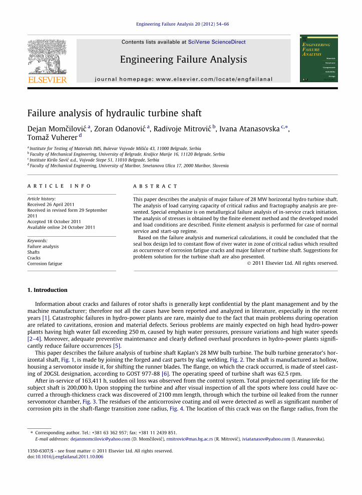
This paper describes the failure analysis of turbine shaft Kaplan’s 28 MW bulb turbine. The bulb turbine generator’s hor-izontal shaft, Fig. 1, is made by joining the forged and cast parts by slag welding, Fig. 2. The shaft is manufactured as hollow,housing a servomotor inside it, for shifting the runner blades. The flange, on which the crack occurred, is made of steel cast-ing of 20GSL designation, according to GOST 977-88 [6]. The operating speed of turbine shaft was 62.5 rpm.
After in-service of 163,411 h, sudden oil loss was observed from the control system. Total projected operating life for thesubject shaft is 200,000 h. Upon stopping the turbine and after visual inspection of all the spots where loss could have oc-curred a through-thickness crack was discovered of 2100 mm length, through which the turbine oil leaked from the runnerservomotor chamber, Fig. 3. The residues of the anticorrosive coating and oil were detected as well as significant number ofcorrosion pits in the shaft-flange transition zone radius, Fig. 4. The location of this crack was on the flange radius, from the
. All rights reserved.
x: +381 11 2439 851.(D. Momcilovic), [email protected] (R. Mitrovic), [email protected] (I. Atanasovska).
Nomenclature
C parameter of Paris-Erdogan equation (–)Fa axial hydraulic force (N)Fp axial force from pressure in servomotor (N)M parameter of Paris-Erdogan equation (–)Mt torque on the runner (Nm)Q pressure in servomotorR servomotor cylinder radius (m); stress ratio (–)R servomotor toggle radius (m)SFL fatigue limit (MPa)x, y, z axes of cartesian coordinate systemDKTH threshold stress intensity, (MPa
pm)
ra amplitude value of total normal stress (Pa)reqv equivalent stresses calculated according to the Von Mises’s criterion (Pa)rn total normal stress (Pa)rsr mean value of total normal stress (Pa)rx normal stress in direction of x axis (Pa)ry normal stress in direction of y axis (Pa)
D. Momcilovic et al. / Engineering Failure Analysis 20 (2012) 54–66 55
cylindrical part of shaft towards the flange to which the runner is connected. After the failure, the shaft was disassembledand flame cut for the inspecting the fracture surface, Fig. 5.
2. Experimental results
2.1. Visual examination
On the basis of visual examination of the crack surface, the multiple fatigue cracks initiations sites were perceived, asshown in Fig. 6, (zone a). In the same figure, the zone of the stable fatigue crack propagation front, (zone b), and the finalphase of instable crack growth are observed. In Fig. 6, (zone c), openings were perceived that had been drilled by mistakein some phase of the flange manufacture. The Fig. 7a and b shows the magnified view of the crack surface zones. Fig. 7ashows front view of fractured surface where are quite obvious ratchet marks that occurred as the result of linking the prop-agation fronts of several fatigue cracks, as well as the stable growth zone. Fig. 7b shows side view of shaft radius with sec-ondary cracks. On the fracture surface, the visible distorted fatigue lines around numerous gas holes and locations ofincreased porosity are observed, Fig. 8.
The overall appearance of the examined crack surface indicates that the fracture occurred due to combined actions oftwisting and bending. The small slant angle of the fatigue surface points to the influence of torsion stresses on cracks for-mation was less influential than the effects of the stress due to bending or tension. It can be seen in Figs. 5 and 6 thatthe through crack makes almost 30% of the total cross section of the shaft, so it is obvious that operating stresses in the frac-ture zone were small [7].
Fig. 1. Disassembled turbine shaft with runner.
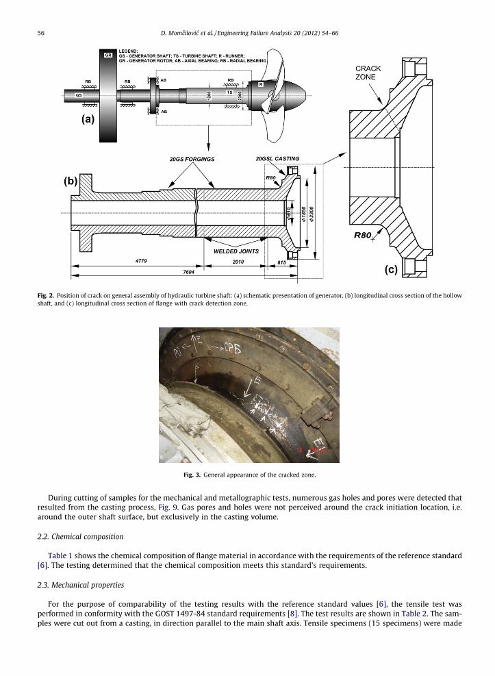
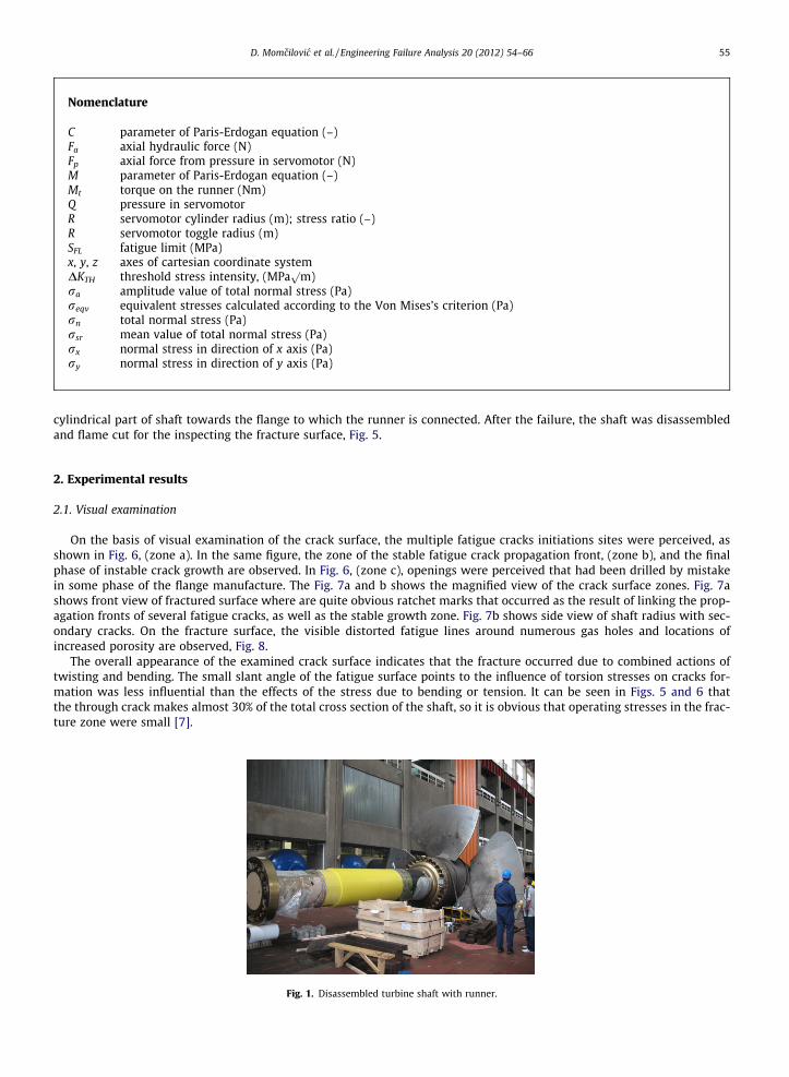
Fig. 2. Position of crack on general assembly of hydraulic turbine shaft: (a) schematic presentation of generator, (b) longitudinal cross section of the hollowshaft, and (c) longitudinal cross section of flange with crack detection zone.
Fig. 3. General appearance of the cracked zone.
56 D. Momcilovic et al. / Engineering Failure Analysis 20 (2012) 54–66
During cutting of samples for the mechanical and metallographic tests, numerous gas holes and pores were detected thatresulted from the casting process, Fig. 9. Gas pores and holes were not perceived around the crack initiation location, i.e.around the outer shaft surface, but exclusively in the casting volume.
2.2. Chemical composition
Table 1 shows the chemical composition of flange material in accordance with the requirements of the reference standard[6]. The testing determined that the chemical composition meets this standard’s requirements.
2.3. Mechanical properties
For the purpose of comparability of the testing results with the reference standard values [6], the tensile test wasperformed in conformity with the GOST 1497-84 standard requirements [8]. The test results are shown in Table 2. The sam-ples were cut out from a casting, in direction parallel to the main shaft axis. Tensile specimens (15 specimens) were made
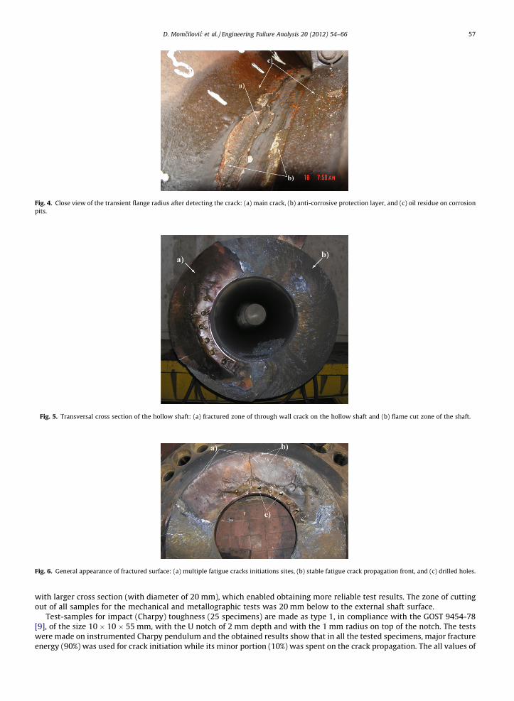
Fig. 4. Close view of the transient flange radius after detecting the crack: (a) main crack, (b) anti-corrosive protection layer, and (c) oil residue on corrosionpits.
Fig. 5. Transversal cross section of the hollow shaft: (a) fractured zone of through wall crack on the hollow shaft and (b) flame cut zone of the shaft.
Fig. 6. General appearance of fractured surface: (a) multiple fatigue cracks initiations sites, (b) stable fatigue crack propagation front, and (c) drilled holes.
D. Momcilovic et al. / Engineering Failure Analysis 20 (2012) 54–66 57
with larger cross section (with diameter of 20 mm), which enabled obtaining more reliable test results. The zone of cuttingout of all samples for the mechanical and metallographic tests was 20 mm below to the external shaft surface.
Test-samples for impact (Charpy) toughness (25 specimens) are made as type 1, in compliance with the GOST 9454-78[9], of the size 10 � 10 � 55 mm, with the U notch of 2 mm depth and with the 1 mm radius on top of the notch. The testswere made on instrumented Charpy pendulum and the obtained results show that in all the tested specimens, major fractureenergy (90%) was used for crack initiation while its minor portion (10%) was spent on the crack propagation. The all values of
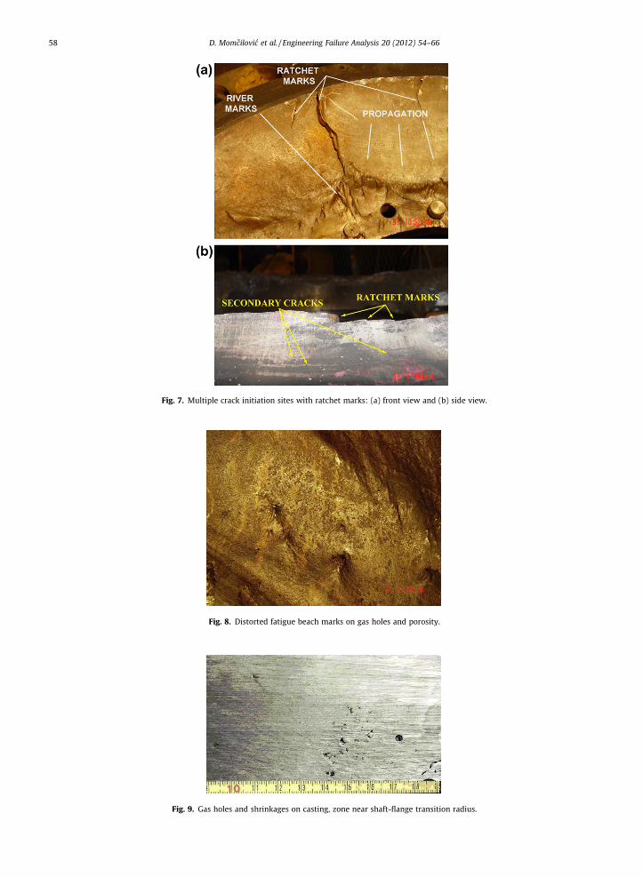
Fig. 7. Multiple crack initiation sites with ratchet marks: (a) front view and (b) side view.
Fig. 8. Distorted fatigue beach marks on gas holes and porosity.
Fig. 9. Gas holes and shrinkages on casting, zone near shaft-flange transition radius.
58 D. Momcilovic et al. / Engineering Failure Analysis 20 (2012) 54–66
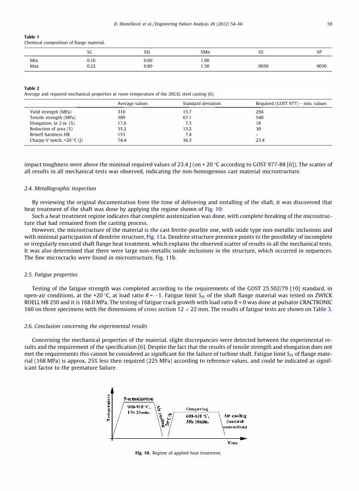
Table 1Chemical composition of flange material.
%C %Si %Mn %S %P
Min 0.16 0.60 1.00Max 0.22 0.80 1.30 0030 0030
Table 2Average and required mechanical properties at room temperature of the 20GSL steel casting [6].
Average values Standard deviation Required (GOST 977) – min. values
Yield strength (MPa) 310 15.7 294Tensile strength (MPa) 509 67.1 540Elongation, in 2 in. (%) 17.6 7.3 18Reduction of area (%) 35.2 13.2 30Brinell hardness HB 153 7.4 –Charpy-V notch, +20 �C (J) 74.4 36.3 23.4
D. Momcilovic et al. / Engineering Failure Analysis 20 (2012) 54–66 59
impact toughness were above the minimal required values of 23.4 J (on + 20 �C according to GOST 977-88 [6]). The scatter ofall results in all mechanical tests was observed, indicating the non-homogenous cast material microstructure.
2.4. Metallographic inspection
By reviewing the original documentation from the time of delivering and installing of the shaft, it was discovered thatheat treatment of the shaft was done by applying the regime shown of Fig. 10:
Such a heat treatment regime indicates that complete austenization was done, with complete breaking of the microstruc-ture that had remained from the casting process.
However, the microstructure of the material is the cast ferrite-pearlite one, with oxide type non-metallic inclusions andwith minimal participation of dendrite structure, Fig. 11a. Dendrite structure presence points to the possibility of incompleteor irregularly executed shaft flange heat treatment, which explains the observed scatter of results in all the mechanical tests.It was also determined that there were large non-metallic oxide inclusions in the structure, which occurred in sequences.The fine microcracks were found in microstructure, Fig. 11b.
2.5. Fatigue properties
Testing of the fatigue strength was completed according to the requirements of the GOST 25.502/79 [10] standard, inopen-air conditions, at the +20 �C, at load ratio R = �1. Fatigue limit SFL of the shaft flange material was tested on ZWICKROELL HB 250 and it is 168.0 MPa. The testing of fatigue crack growth with load ratio R = 0 was done at pulsator CRACTRONIC160 on three specimens with the dimensions of cross section 12 � 22 mm. The results of fatigue tests are shown on Table 3.
2.6. Conclusion concerning the experimental results
Concerning the mechanical properties of the material, slight discrepancies were detected between the experimental re-sults and the requirement of the specification [6]. Despite the fact that the results of tensile strength and elongation does notmet the requirements this cannot be considered as significant for the failure of turbine shaft. Fatigue limit SFL of flange mate-rial (168 MPa) is approx. 25% less then required (225 MPa) according to reference values, and could be indicated as signif-icant factor to the premature failure.
Fig. 10. Regime of applied heat treatment.
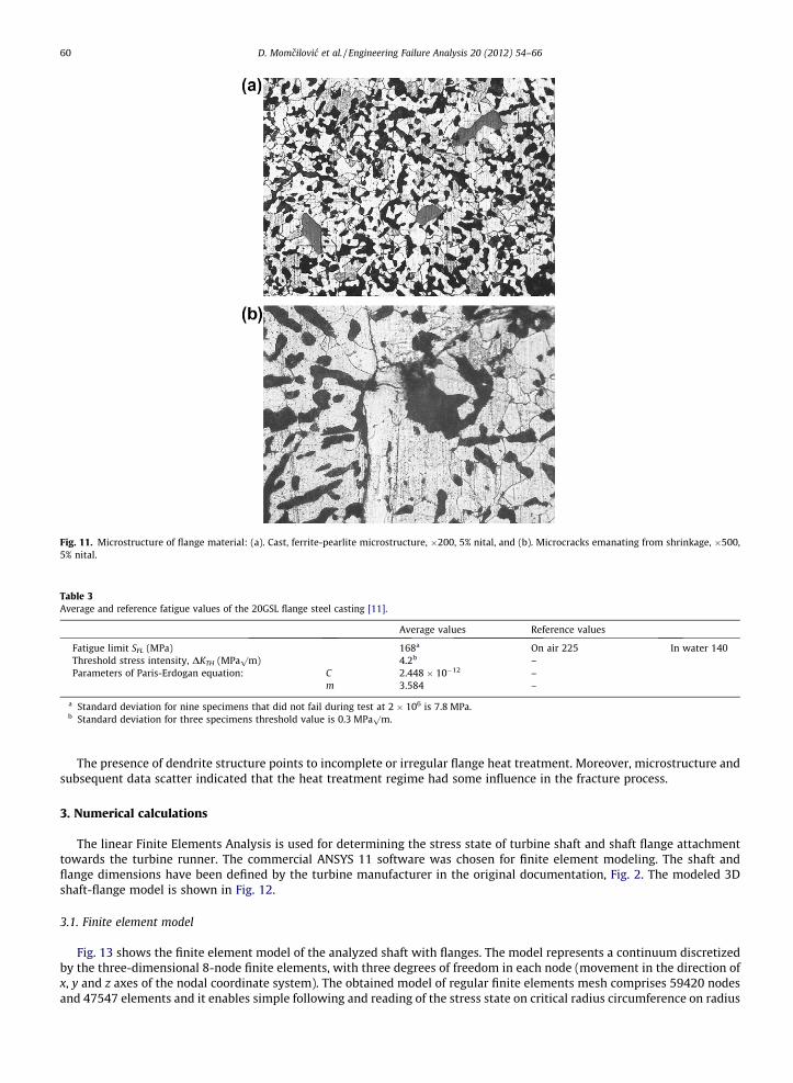
Fig. 11. Microstructure of flange material: (a). Cast, ferrite-pearlite microstructure, �200, 5% nital, and (b). Microcracks emanating from shrinkage, �500,5% nital.
Table 3Average and reference fatigue values of the 20GSL flange steel casting [11].
Average values Reference values
Fatigue limit SFL (MPa) 168a On air 225 In water 140Threshold stress intensity, DKTH (MPa
pm) 4.2b –
Parameters of Paris-Erdogan equation: C 2.448 � 10�12 –m 3.584 –
a Standard deviation for nine specimens that did not fail during test at 2 � 106 is 7.8 MPa.b Standard deviation for three specimens threshold value is 0.3 MPa
pm.
60 D. Momcilovic et al. / Engineering Failure Analysis 20 (2012) 54–66
The presence of dendrite structure points to incomplete or irregular flange heat treatment. Moreover, microstructure andsubsequent data scatter indicated that the heat treatment regime had some influence in the fracture process.
3. Numerical calculations
The linear Finite Elements Analysis is used for determining the stress state of turbine shaft and shaft flange attachmenttowards the turbine runner. The commercial ANSYS 11 software was chosen for finite element modeling. The shaft andflange dimensions have been defined by the turbine manufacturer in the original documentation, Fig. 2. The modeled 3Dshaft-flange model is shown in Fig. 12.
3.1. Finite element model
Fig. 13 shows the finite element model of the analyzed shaft with flanges. The model represents a continuum discretizedby the three-dimensional 8-node finite elements, with three degrees of freedom in each node (movement in the direction ofx, y and z axes of the nodal coordinate system). The obtained model of regular finite elements mesh comprises 59420 nodesand 47547 elements and it enables simple following and reading of the stress state on critical radius circumference on radius
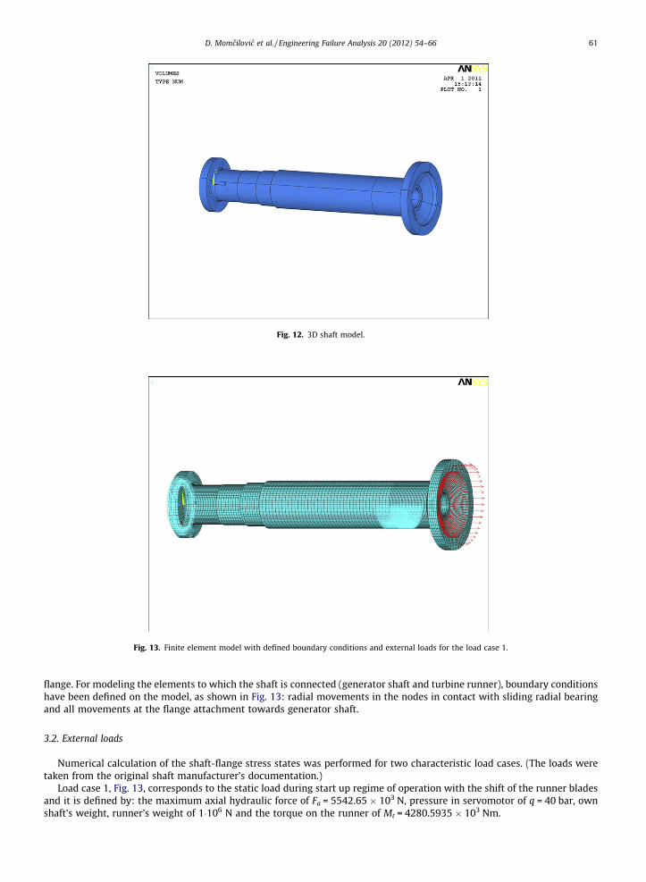
Fig. 12. 3D shaft model.
Fig. 13. Finite element model with defined boundary conditions and external loads for the load case 1.
D. Momcilovic et al. / Engineering Failure Analysis 20 (2012) 54–66 61
flange. For modeling the elements to which the shaft is connected (generator shaft and turbine runner), boundary conditionshave been defined on the model, as shown in Fig. 13: radial movements in the nodes in contact with sliding radial bearingand all movements at the flange attachment towards generator shaft.
3.2. External loads
Numerical calculation of the shaft-flange stress states was performed for two characteristic load cases. (The loads weretaken from the original shaft manufacturer’s documentation.)
Load case 1, Fig. 13, corresponds to the static load during start up regime of operation with the shift of the runner bladesand it is defined by: the maximum axial hydraulic force of Fa = 5542.65 � 103 N, pressure in servomotor of q = 40 bar, ownshaft’s weight, runner’s weight of 1�106 N and the torque on the runner of Mt = 4280.5935 � 103 Nm.
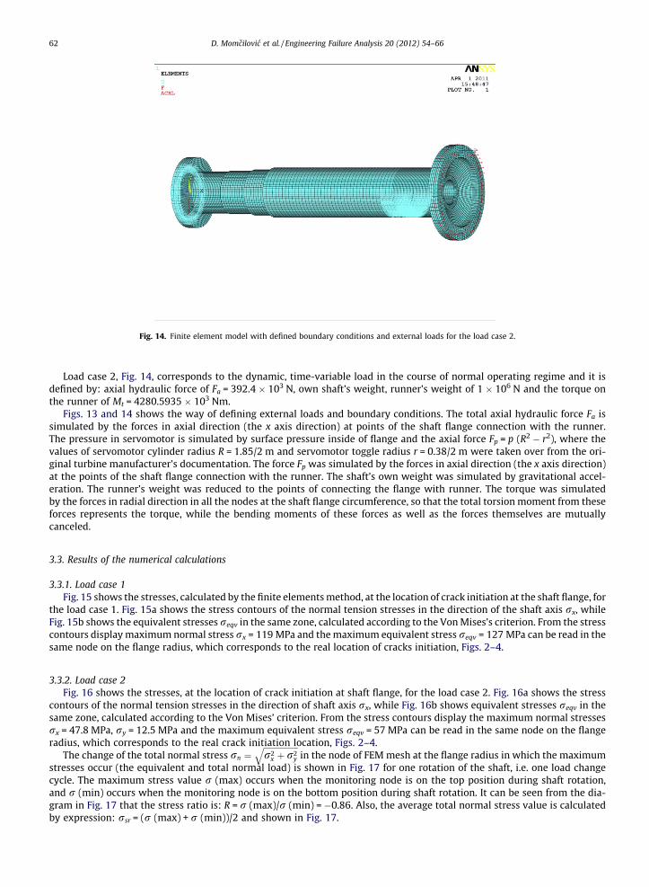
Fig. 14. Finite element model with defined boundary conditions and external loads for the load case 2.
62 D. Momcilovic et al. / Engineering Failure Analysis 20 (2012) 54–66
Load case 2, Fig. 14, corresponds to the dynamic, time-variable load in the course of normal operating regime and it isdefined by: axial hydraulic force of Fa = 392.4 � 103 N, own shaft’s weight, runner’s weight of 1 � 106 N and the torque onthe runner of Mt = 4280.5935 � 103 Nm.
Figs. 13 and 14 shows the way of defining external loads and boundary conditions. The total axial hydraulic force Fa issimulated by the forces in axial direction (the x axis direction) at points of the shaft flange connection with the runner.The pressure in servomotor is simulated by surface pressure inside of flange and the axial force Fp = p (R2 � r2), where thevalues of servomotor cylinder radius R = 1.85/2 m and servomotor toggle radius r = 0.38/2 m were taken over from the ori-ginal turbine manufacturer’s documentation. The force Fp was simulated by the forces in axial direction (the x axis direction)at the points of the shaft flange connection with the runner. The shaft’s own weight was simulated by gravitational accel-eration. The runner’s weight was reduced to the points of connecting the flange with runner. The torque was simulatedby the forces in radial direction in all the nodes at the shaft flange circumference, so that the total torsion moment from theseforces represents the torque, while the bending moments of these forces as well as the forces themselves are mutuallycanceled.
3.3. Results of the numerical calculations
3.3.1. Load case 1Fig. 15 shows the stresses, calculated by the finite elements method, at the location of crack initiation at the shaft flange, for
the load case 1. Fig. 15a shows the stress contours of the normal tension stresses in the direction of the shaft axis rx, whileFig. 15b shows the equivalent stresses reqv in the same zone, calculated according to the Von Mises’s criterion. From the stresscontours display maximum normal stress rx = 119 MPa and the maximum equivalent stress reqv = 127 MPa can be read in thesame node on the flange radius, which corresponds to the real location of cracks initiation, Figs. 2–4.
3.3.2. Load case 2Fig. 16 shows the stresses, at the location of crack initiation at shaft flange, for the load case 2. Fig. 16a shows the stress
contours of the normal tension stresses in the direction of shaft axis rx, while Fig. 16b shows equivalent stresses reqv in thesame zone, calculated according to the Von Mises’ criterion. From the stress contours display the maximum normal stressesrx = 47.8 MPa, ry = 12.5 MPa and the maximum equivalent stress reqv = 57 MPa can be read in the same node on the flangeradius, which corresponds to the real crack initiation location, Figs. 2–4.
The change of the total normal stress rn ¼ffiffiffiffiffiffiffiffiffiffiffiffiffiffiffiffiffir2
x þ r2y
qin the node of FEM mesh at the flange radius in which the maximum
stresses occur (the equivalent and total normal load) is shown in Fig. 17 for one rotation of the shaft, i.e. one load changecycle. The maximum stress value r (max) occurs when the monitoring node is on the top position during shaft rotation,and r (min) occurs when the monitoring node is on the bottom position during shaft rotation. It can be seen from the dia-gram in Fig. 17 that the stress ratio is: R = r (max)/r (min) = �0.86. Also, the average total normal stress value is calculatedby expression: rsr = (r (max) + r (min))/2 and shown in Fig. 17.
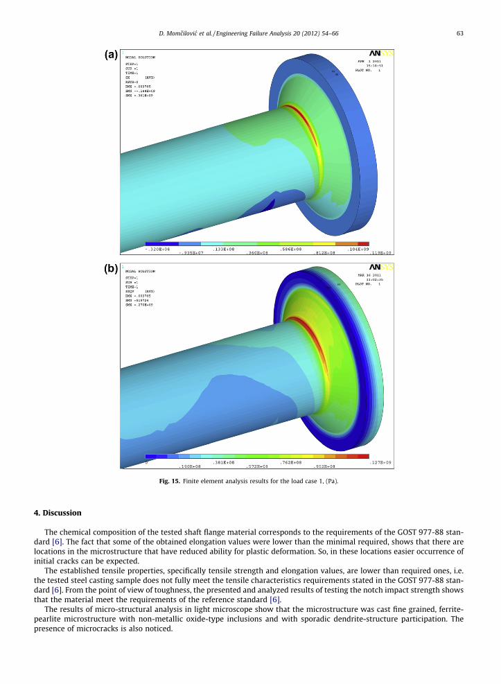
Fig. 15. Finite element analysis results for the load case 1, (Pa).
D. Momcilovic et al. / Engineering Failure Analysis 20 (2012) 54–66 63
4. Discussion
The chemical composition of the tested shaft flange material corresponds to the requirements of the GOST 977-88 stan-dard [6]. The fact that some of the obtained elongation values were lower than the minimal required, shows that there arelocations in the microstructure that have reduced ability for plastic deformation. So, in these locations easier occurrence ofinitial cracks can be expected.
The established tensile properties, specifically tensile strength and elongation values, are lower than required ones, i.e.the tested steel casting sample does not fully meet the tensile characteristics requirements stated in the GOST 977-88 stan-dard [6]. From the point of view of toughness, the presented and analyzed results of testing the notch impact strength showsthat the material meet the requirements of the reference standard [6].
The results of micro-structural analysis in light microscope show that the microstructure was cast fine grained, ferrite-pearlite microstructure with non-metallic oxide-type inclusions and with sporadic dendrite-structure participation. Thepresence of microcracks is also noticed.
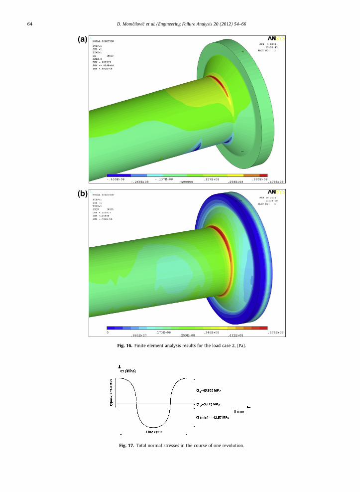
Fig. 16. Finite element analysis results for the load case 2, (Pa).
Fig. 17. Total normal stresses in the course of one revolution.
64 D. Momcilovic et al. / Engineering Failure Analysis 20 (2012) 54–66
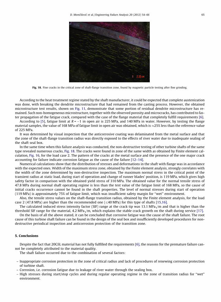
Fig. 18. Fine cracks in the critical zone of shaft-flange transition zone, found by magnetic particle testing after fine grinding.
D. Momcilovic et al. / Engineering Failure Analysis 20 (2012) 54–66 65
According to the heat treatment regime stated by the shaft manufacturer, it could be expected that complete austenizationwas done, with breaking the dendrite microstructure that had remained from the casting process. However, the obtainedmicrostructure test results, shown on Fig. 11, demonstrate that some portion of residual dendrite microstructure has re-mained. Such non-homogeneous microstructure, together with the observed porosity and microcracks, has contributed to fas-ter propagation of the fatigue crack, compared with the case of the flange material that completely fulfill requirements [6].
According to [5], fatigue limit at R = �1 in open air is 225 MPa, and 140 MPa in water. However, by testing the flangematerial samples, the value of 168 MPa of fatigue limit in open air was obtained, which is �25% less than the reference valueof 225 MPa.
It was determined by visual inspection that the anticorrosive coating was delaminated from the metal surface and thatthe zone of the shaft-flange transition radius was directly exposed to the effects of river water due to inadequate sealing ofthe shaft seal box.
In the same time when this failure analysis was conducted, the non-destructive testing of other turbine shafts of the sametype revealed numerous cracks, Fig. 18. The cracks were found in zone of the same width as obtained by Finite element cal-culation, Fig. 16, for the load case 2. The pattern of the cracks at the metal surface and the presence of the one major crackaccounting for failure indicate corrosion fatigue as the cause of the failure [12–14].
Numerical calculations show that the distribution of stresses and deformations in the shaft with flange was in accordancewith the expected ones. Width of the maximum stress zone, obtained by the Finite element analysis, strongly correlates withthe width of the zone determined by non-destructive inspection. The maximum normal stress in the critical point of thetransient radius at static load, during start of operation and change of runner blades’ position, is 119 MPa, which gives highsafety factor in comparison with the obtained yield stress of 310 MPa. The obtained value for the normal tensile stress of47.8 MPa during normal shaft operating regime is less than the test value of the fatigue limit of 168 MPa, so the cause ofinitial cracks occurrence cannot be found in the shaft properties. The level of normal stresses during start of operation(119 MPa) is approximately 75% of fatigue limit, which was insufficient safety margin for ‘‘wet’’ environment.
Also, the tensile stress values on the shaft-flange transition radius, obtained by the Finite element analysis, for the loadcase 2 (47.8 MPa) are higher than the recommended one (640 MPa) for this type of shafts [15,16].
The calculated induced stress intensity factor (SIF) range at the crack tip was 13.1 MPap
m and that is higher than thethreshold SIF range for the material, 4.2 MPa
pm, which explains the stable crack growth on the shaft during service [17].
On the basis of all the above stated, it can be concluded that corrosive fatigue was the cause of the shaft failure. The rootcause of this turbine shaft failure can be found in the design of the seal box and insufficiently developed procedures for non-destructive periodical inspection and anticorrosion protection of the transition zone.
5. Conclusions
Despite the fact that 20GSL material has not fully fulfilled the requirements [6], the reasons for the premature failure can-not be completely attributed to the material quality.
The shaft failure occurred due to the combination of several factors:
– Inappropriate corrosion protection in the zone of critical radius and lack of procedures of renewing corrosion protectionof turbine shaft.
– Corrosion, i.e. corrosion fatigue due to leakage of river water through the sealing box.– High stresses during start/stop cycles and during regular operating regime in the zone of transition radius for ‘‘wet’’
environment.
66 D. Momcilovic et al. / Engineering Failure Analysis 20 (2012) 54–66
The following suggestions emerged from this failure analysis:
– Redesign of the seal box in order to eliminate of water leakage into the shaft-flange transition zone.– Redefining of procedures for periodical non-destructive inspection of the shaft-flange transition zone status, with
increased frequency.– Periodical renewal of the anticorrosive protection on the shaft flange, especially in the shaft-flange transition zone.– Checking the possibility for redesign the transient radius for reducing the stress level at critical radius.– Keeping the start/stop cycles at minimal values as it is possible.– Considering an improvement of general technical conditions of delivery for flange material upon a new commissioning.
Acknowledgements
Parts of this research were supported by the Ministry of Sciences and Technology of Republic of Serbia Grant TR35029 – Development of Methodology for Improvement of Operational Performance, Reliability and Energy Efficiency of Ma-chine Systems used in the Resource Industry.
References
[1] Bachschmid N, Pennacchi P, Tanzi E. Cracked rotors – a survey on static and dynamic behavior including modelling and diagnosis. Heidelberg-Berlin: Springer; 2010.
[2] Braitsch W, Haas H. Turbines for hydroelectric power. In: Heinloth K, editor. Landolt-Börnstein, group VIII: advanced materials and technologies, vol. 3:energy technologies, subvol. C: renewable energies. Heidelberg-Berlin: Springer Verlag; 2006. p. 493–604.
[3] Arne Kjølle. Hydropower in Norway – mechanical equipment, survey, NTNU. Department of energy and process engineering. Trondheim; 2001.[4] Egusquiza E, Valero C, Estévez A, Guardo A, Coussirat M. Failures due to ingested bodies in hydraulic turbines. Eng Fail Anal 2011;18:464–73.[5] Bulloch JH, Callagy AG. An detailed integrity assessment of a 25 MW hydro-electric power station penstock. Eng Fail Anal 2010;17:387–93.[6] GOST 977-88, Steel Catings. General Specification; 1988.[7] Wulpi DJ. Failures of shafts, in ASM handbook. Failure analysis and prevention, vol 11. ASM International; 2002.[8] GOST 1497-84, Metals. Methods of tension test; 1984.[9] GOST 9454-78, Metals. Method for testing the impact strength at low, room and high temperature; 1978.
[10] GOST 25.502-79 – Strength analysis and testing in machine building. Methods of metals mechanical testing. Methods of fatigue testing; 1979.[11] Troschenko VT. Fatigue resistance of metals and alloys. Naukova Dumka; 1987. p. 668–70. [in Russian].[12] Winston Revie R, Uhlig Herbert H. Corrosion and corrosion control. John Wiley & Sons, Inc; 2008.[13] Gangloff RP. Corrosion fatigue cracking, in corrosion tests and standards: application and interpretation. In: Baboian R, editor. ASM International; 2005.
p. 302–21 [2nd ed.].[14] Ebara R. Corrosion fatigue phenomena learned from failure analysis. Eng Fail Anal 2006;13:516–25.[15] Maricic T, Haber D, Pejovic S. Standardization as prevention of fatigue cracking of hydraulic turbine-generator shaft. In: Proceedings of IEEE electrical
power conference on CD, Montreal; 2007.[16] Atanasovska, Mitrovic R, Momcilovic D. FEM model for calculation of hydro turbine shaft. In: Proceedings – the sixth international symposium KOD
2010, 29–30.09.2010. Palic, Serbia, Published by Faculty of Technical Science – Novi Sad, Serbia; 2010. p. 183–8.[17] Döker H. Fatigue crack growth threshold: implications, determination and data evaluation. Int J Fatigue 1997;19(1):S145–9.