development of 100 mw gas turbine shaft sleeve
TRANSCRIPT
Nigerian Journal of Technology (NIJOTECH)Vol. 31, No. 3, November, 2012, pp. 383–392.
Copyright 2012 Faculty of Engineering,
University of Nigeria. ISSN 1115-8443
DEVELOPMENT OF 100 MW GAS TURBINE SHAFT SLEEVE
PULLER
E.G. Sadjerea, G.O. Ariavie1,b, P.O. Ebunilo2,b
aNiger Delta Development Commission, 167 Aba Road, Port Harcourt, Nigeria. Email: [email protected] of Mechanical Engineering, University of Benin, Nigeria.
Emails: [email protected]; [email protected]
Abstract
A Shaft Sleeve Puller was developed, designed and constructed in response to the need to pull-out/ pull-in the 30-tonnes by 12m long rotor of the 100-MW gas turbine generator for inspection,as part of a refurbishment programme of a power station in Delta State, Nigeria. The designis a runway system, consisting of a platform incorporating rails on which the carriages run asthey bear the rotor being pulled with a pulling jack. We utilized statically indeterminate approachto design the platform to very high flexural rigidity to avoid deflection, a necessary condition, toprevent damage to the generator field winding. The design was successful; the system constructedand used to pull-out/pull-in six rotors of the gas turbine generators; and is still being stored forfurther use when the need arises.
Keywords: shaft sleeve puller, turbine generator, pull-out/pull-in turbine generator, refurbishment, statisticallydeterminate
1. Introduction
Power generating stations are built in many coun-tries and oftentimes they are built in remote areasas dictated by the energy sources. There are hydro-electric, gas-turbine, steam-turbine, coal-fired, nu-clear and hydro-thermal plants. New technologies,most of which are still being developed to harnessdifferent forms of energy, include wave, wind-turbine,solar-thermal, solar-photovoltaic, fuel-cells and otherchemical methods. Traditional electricity generationis based on the principle of electromagnetic induction[1] and most of the sources enumerated above act asfuels to run the prime mover that drives the generator.A typical gas power plant comprises of the starter mo-tor, the torque converter, the gas turbine, the gearboxand the generator [2]. There are, also, the air and gasintake, as well as, the exhaust systems. The centralelectrical source in the power plants is the generatormodeled essentially of the stationary field winding andthe rotor of wound coils [3].
The power plant units increase in size and weightas the generating capacity increases. The weight ofthe turbine of a 100-MW plant is 30 tonnes whilethat for a 780-MW plant is 250 tonnes. Thus, dur-ing maintenance, plants are often dismantled at loca-tion, and moved out for inspection and maintenance.
The maintenance of power plants involves lifting ofweights and shifting them around and this has poseda challenge to power plant maintenance. Sometimes,maintenance involves replacing turbine blades, gearboxes, alignment of units, air inlet modification andexhaust system alignment, as well as, insulation andcladding. This creates the need to pull out the rotorsof the generator assembly for inspection, as part of therefurbishment/maintenance schedule. The alternativeoption would have been to import a pull-out / pull-in unit from the manufacturer at huge cost or havethe turbine refurbished at the manufacturers facilityin the US due to lack of local capacity.
2. Problem of Generator Rotor Puller
The generator rotor is a cylindrical drum of approx-imately 1.0m diameter × 12.0m long and has a deadweight of 30 tonnes mounted concentrically in the fieldwinding of the generator. The main consideration inpulling out the rotor from the field winding is thatthe rotor must remain suspended in its horizontal po-sition, maintaining the concentricity in the field wind-ing so that it does not drop and scratch or damagethe field winding. The space between the generatorand the transformer bund-wall is only 14m and thereis no space for the use of heavy duty mobile cranes.
Nigerian Journal of Technology Vol. 31, No. 3, November 2012.
384 E.G. SADJERE, G.O. ARIAVIE & P.O. EBUNILO
������������
���� ���
�����
����
��������
����
�����������
����
������
�����������
����������
!����"����#
����
��$���
�%��
������
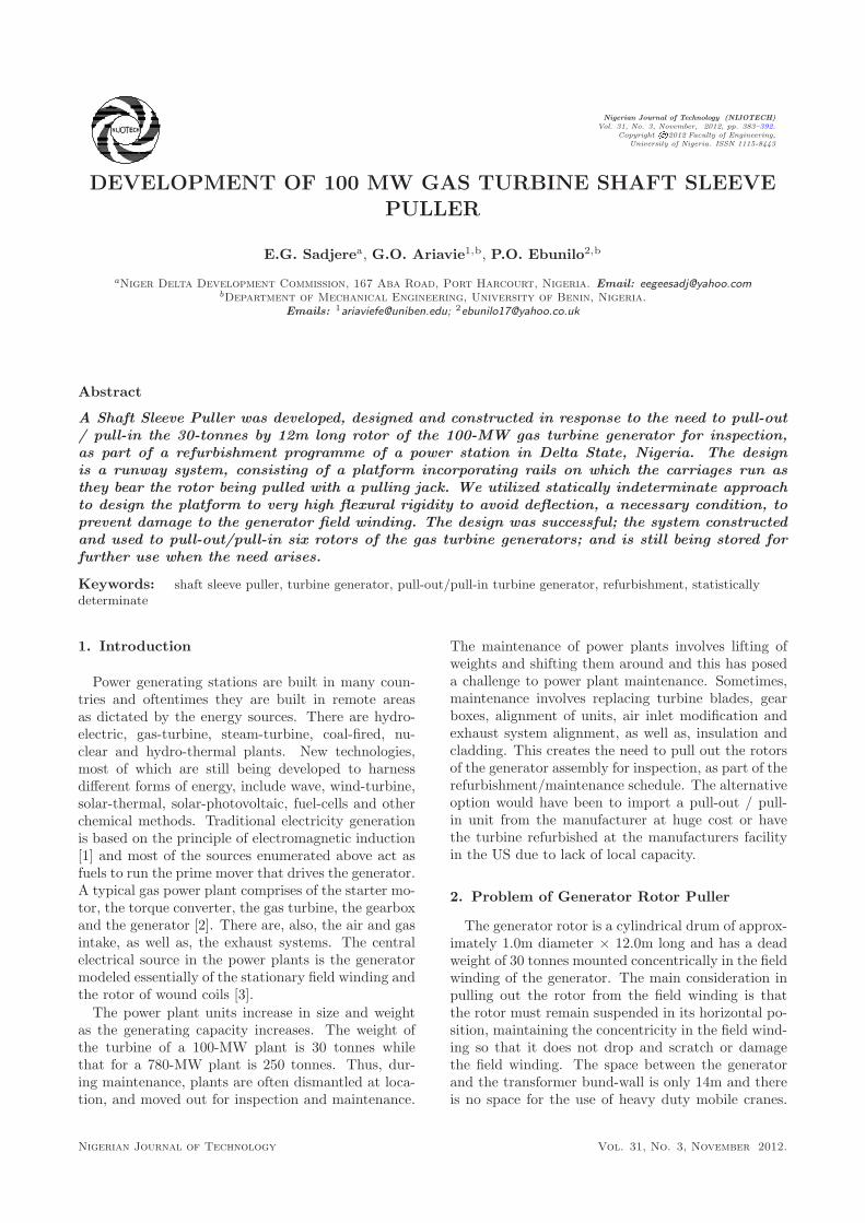
Figure 1: Conceptual design of the sleeve rotor puller mechanism.
The equipment manufacturer, General Electric, hadnot provided specific equipment or instructions for thepull out of rotors for inspection or description of suchoperation in the GE Reference Documents (GERs) [5].However, equipment manufacturers were expected tosupply special tools to be incorporated in the run-way method to pull in, pull out rotors of generators.When such are not supplied, maintenance or serviceteams will have to fabricate special tools for that pur-pose. A blog by Siswanto [6], described the removalof the rotor of a 125-MW generator. A jacking railwas constructed and a combination using jacking andchain block were installed to pull out the rotor. How-ever, due to space and time constraints, the rails weresupported by wooden framework. This illustrates de-cisions that have to be taken depending on site con-ditions [4].
2.1. Design calculations
2.1.1. Design considerations
1. A system that is rigid and strong enough to carrythe weight of the rotor and whose columns shouldnot buckle under the weight of the load, keepinghorizontal members horizontal with minimal deflec-tion.
2. The effort required to pull this dead weight outshould be minimal so it must be designed for lowfriction.
3. The drum is not allowed to touch any part of thefield winding, such that apart from horizontally,the body should remain as concentric as possibleand hence must also be constrained on its lateralmovement.
4. The system must be stable and not subjected toaxial movement during operation.
5. The design should incorporate means of attach-ment for the application of the pulling force.
6. The system should be designed for mounting anddismantling because the unit should be closed afterinspection and the system should be re-assembledfor another inspection.
The design consists of a platform on which ismounted carriages with adjustable power screws toadjust the levels of the saddle and a come-along jackattached to a frame at one end of the platform to pullthe rotor (fig. 1). The following are the features ofthe mechanism. The sleeve rotor puller mechanismwas conceptualized to consist of a platform, the topof which will incorporate rails for tracking the rotor asit is being pulled out from the generator field windingsleeve. Pulling will be accomplished with a pullingjack (come-along) attached to a frame at the end ofthe platform. The following are the characteristics ofthe design.
1. The platform is of rigid but bolted constructionand made of I-beams designed to withstand the 30tonnes load.
2. There are two sets of columns due to the differentelevations of the floor area for the mounting of thesystem.
3. The columns are struts or short columns with slen-derness ratio (L/r < 30)[7] to prevent buckling dueto the high load
4. Columns 3 and 4 are interconnected to providefixed point for the structure and prevent axialmovement during operation.
5. The carriages are on rollers, the ones on one sideare grooved while those on the other side are plain.They are to run on rails fixed on top of the plat-form.
6. The grooving of only one side rollers keeps the car-riage on a straight track while friction is reducedand possibility of jamming prevented.
7. All carriages incorporate adjustable screws to keepthe rotor level and maintain its horizontality.
Nigerian Journal of Technology Vol. 31, No. 3, November 2012.
Development of 100 MW Gas Turbine Shaft Sleeve Puller 385
8. The end carriages have couplings to connect to theshaft of the rotor and eyes for attachment of thepuller hook.
9. The inner carriages have the top parts of their sad-dles constructed in two halves, which were assem-bled in situ on top of the carriage as the rotor isbeing pulled out.
10. The top of the saddles and the clamps are linedwith Neoprene materials to minimize scratches ordamage to the rotor surface.
Fig. 1 shows the side elevation and end view of theconceptual design with the rotor fully on top of theplatform, after pull out.
2.1.2. Column design
The platform is made up of the columns, majorbeams, cross beams and tie-beams. The column de-sign comprised the determination of the load andreactions, stress calculations and size estimation ofcolumns.
i. Load and Reactions
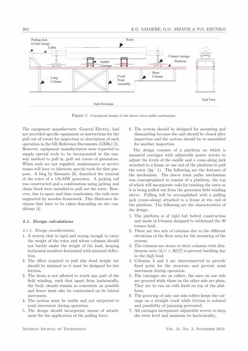
When the load is completely resting on the platform,the distribution of the carriages, the load transmittedthrough the rollers and the reactions from the columnsupports are as shown in the free body diagram of onearm of the platform (Fig. 2).The load transmitted from the carriage rollers areat the mid-section between columns and are 700mmapart, which is the spacing between the rollers and arerepresented as W1 to W4. The reaction from the fivecolumn support have been designated RA to RE. Thecolumns and beams are bolted and hence representfixed supports. The structure is statically indetermi-nate [7] and [8]. However, the following assumptionswere made to simplify the resolution of the forces anddetermine the reactions and bending moments at thesupports.1. The beam is considered to be made up of 4 seg-
ments each of which has both ends fixed.2. Each segment carries 1/4 of the weight of the rotor
and the weight is treated as point loads appliedthrough the rollers 700mm apart at mid section ofthe span.
3. As a further simplification, the loads W1a andW1bare considered as a single load W1 acting at mid-span of segment
4. The beam is initially assumed weightless, an ideal-ization necessary because the size of the beam wasyet unknown.
Based on above assumptions, we applied the equationsfor the reactions and deflections of statically indeter-minate beams with fixed ends [7] and [8].
RA = RB1 =W1L1
2(1)
MA = MB1 =W1L1
8(2)
νmax = νc =W1L
31
192EI(3)
Where, W1 = weight of segment and L1 = length ofsegment. For sections AB, BC, CD and DE
RA = RB1; RB2 = RC1 RC2 = RD1 RD2 = RE (4)
Mass of rotor = 30 tonnes = 30,000 kg; hence weightof Rotor = 300 kN. Load on one beam = 150 kN; loadon each segment of beam, W1 = W2 = W3 = W4 =150
4= 37.5kN. Reactions at columns RA = RB1 =
RB2 = RC1 = RE = 37.52
= 18.75kN. Reactions atRB = RC = RD = RB1 + RB2 = 37.5kN. Thus,the three inner supports are each carrying twice theweight carried by the outer supports. The load perroller (8 rollers per beam) is W1a = W1b = W2a =W2b = W3a = W3b = W4a = W4b =
150
8= 18.75kN.
ii. Size Estimation
Since the inner columns, B, C and D, bear the highestload, maximum stress is experienced in these columnsand the column design is based on forces and mo-ments on these members. For rigidity, the columnsare assumed to be short columns (L/r < 30); i.e. theslenderness ratio or ratio of length of column to ra-dius of gyration is less than 30. The lengths of thelong columns are taken as 2m, determined by the ver-tical height of the central axis of the rotor drum andafter making provision for the carriage.We assume L/r = λ = 25; therefore, r = 80 mm.An I-beam with a radius of gyration, r = 80 mm wasread from American Standard I-beam. Table A-7 [7],which is S 200 × 27 for narrow beams with the nearestr of r = 82.8. The nearest to the choice above in theInternational Standard Organization reference for I-beams in the narrow flange I-beam is the ISMB 200,with corresponding radius of gyration r = 93.1 andhas weight of 25.4 kg/m, depth of section, D = 200mmand width of flange, b = 100mm [1].
iii. Stress Analysis
For the short column, the stress is contributed by boththe axial load and the bending moment. That is,
Maximum Stress, σmax =W
A+
M
z(5)
Where, W = axial load; A = area; M = bendingmoment and z = section modulus. The maximumaxial load and bending moment are on columns B, Cand D, hence designing for either B,C and D would beadequate.Considering column B, and substituting in Eq. 5, wehave
∴ σmax =W
A+
M
z= 130MPa
Therefore, the maximum stress due to axial load andbending moment as a result of eccentric loading is 130MPa. We had chosen a structural steel with yield
Nigerian Journal of Technology Vol. 31, No. 3, November 2012.
386 E.G. SADJERE, G.O. ARIAVIE & P.O. EBUNILO
�
�
�
Figure 2: Free-body diagram of platform load and reactions.
stress of 250 MPa. The permissible axial load in com-pression for columns of slenderness ratio, λ = 25 is146 MPa [10]. (see appendix A).
iv. Deflection of Beam
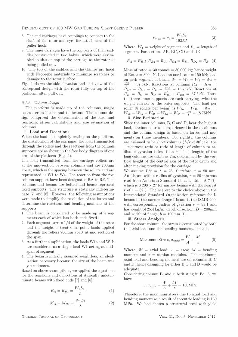
The deflection of the beam was investigated becausethe platform is required to have high flexural rigid-ity or near zero deflection. The deflections due tothe point load and own-weight were considered in theanalysis that follows.The maximum deflection is given by Eq. 3 assuminga weightless beam with point load.
νmax p = νcp = −
W1L3
192EI(6)
Therefore, νmax p = νcp = −1.0986mm. The deflec-tion due to the point load = - 1.0986 mm.The maximum deflection of a beam fixed at both endsis [10]:
νmax d = νcd = −
wL4
1384EI(7)
Where w = weight per m of the beam = 27 kg/m or270 N/m. Therefore, νmax d = νcd = −0.0119mm.Hence, total deflection νmax = νmax p + νmax d =1.0986 + 0.0119 = 1.11mm. The deflection of 1.11mmis permissible to maintain horizontality and rigiditysince for this beam span/325, which in this case, wouldbe 9.2mm, is allowed for structures [9].
v. Bending Stress in Beam
The maximum normal stress due to bending of thisfixed beam is determined from the equation:
σmax =M1
z(8)
Where
M1 =W1L
8+
wL2
12
With M1 = bending moment contributed by bothpoint load and weight of the beam; W1 = weight of
segment 1; w = weight per m and L = length of seg-ment. Calculated value for M1 gives = 14062.5 (Nm)+ 67.5 (Nm) = 14.13 kNm and substituting in Eq. 8would yield σmax = 59.59 N/mm2.
The permissible maximum stress, as a function of theslenderness ratio (D/T = 18.8) and r = 87 wouldyield 130MPa [10]. The design of the platform wasdeemed satisfactory. However, due to none availabil-ity of the above size of I-Beam as determined, theplatform was redesigned for a beam with slendernessratio λ = 20 leading to the choice of wide flange I-beams, W250 x 67, used for the construction.
2.1.3. Leveling bolt
The Leveling Bolt bears the rotor drum with thefour (4) carriages, each with four (4) bolts support-ing the saddle. The bolts act as unrestrained simplesupport. Bolt design is based on tensile strength butpossible failure is tested against shear force on thethread of the bolt and nut. The design stress for boltsby Seaton and Routhewaite [10] is taken as:
σd =σy(As)
1/2
6or Fd =
σy(As)3/2
6(9)
Where σd = design stress; σy = yield stress; As =tensile stress area; and Fd = design load.
This is a high load bolt design and high strengthmaterial is required. Alloyed Medium Carbon Steel,Delta Steel Company Standard HTS 320, equivalentto AISI 4140 was recommended for the production ofthe bolt, [11], [12]. This is a heat treatable steel thatcould be used directly as normalized. The material,AISI 4140, does not exhibit defined yield stress so thedesign was based on the ultimate stress.
Usually, 0.4σy is used when the diameter of the boltis above 18mm but when the determining stress is theultimate stress, the equation will have to be modifiedby a new factor of safety based on ultimate stress of
Nigerian Journal of Technology Vol. 31, No. 3, November 2012.
Development of 100 MW Gas Turbine Shaft Sleeve Puller 387
��
�
Figure 3: Free-body Diagram of Segment of Main Beam in Deflection and Free-Body Diagram of the Distributed Load of Beam
Self-Weight.
at least 4. Therefore,
σd =σy(As)
1/2
24or Fd =
σy(As)3/2
24(10)
From equation 10, calculated value for As =58.989mm2 which is equivalent to metric thread boltM10 with bolt diameter = 10 mm. However, consid-ering the free length of bolt (300mm to give necessaryadjustment clearance), and the need for it to be sturdyand not buckle in operation, a bolt size with slender-ness ratio of 15 was chosen. This gave a bolt of 20mmradius or 40mm diameter. Actually a 2′′ or 50mm di-ameter × 300mm length made from HTS 320 or AISI4140 was used.
2.1.4. Others elements
Other elements like the bearings, rollers and pullingjack were chosen with reference to manufacturingmanuals and accepted operating load. Bearing wasNu2208 Roller bearing for load above 22 kN. Rollerswere machined from HTS 320 while an 8 Ton pullingjack was chosen when the calculated cable tension wastaken as 4.5 Ton for assumed coefficient of friction of0.15.
3. Construction
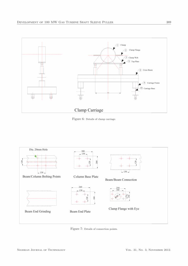
The platform consists of two straight full length ofW250 × 67 × 12m long I-beam on which were laid50 × 50 bars to serve as rails for the carriages. Thebeams were connected with cross beams, end-groundand welded to end-plates, to fit the web. The inter-connected frame was placed on three pairs of longcolumns and two pairs of short columns; all withbase plates for bolting to the beam and to ground.Columns 3 and 4 were interconnected as fixed point toprevent axial movement during operation. The framefor attachment of the pulling jack was fixed to the endof the platform (figure 4).
The main feature of the saddle carriage is the slidingtop (figure 5). The top, made of 10mm plate, wasrolled to fit using a radius of 500mm and an includedangle of 97◦. The curved top is welded to the slidingplate and supported by gussets. This sliding unit iscut longitudinally in two and usually slid from eitherside of the rotor during operation. The top is linedwith conveyor belt to prevent metal-to-metal contact.
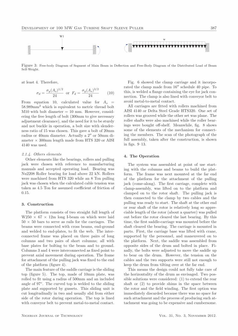
Fig. 6 showed the clamp carriage and it incorpo-rated the clamp made from 16′′ schedule 40 pipe. Tothis, is welded a flange containing the eye for jack con-nection. The clamp is also lined with conveyor belt toavoid metal-to-metal contact.
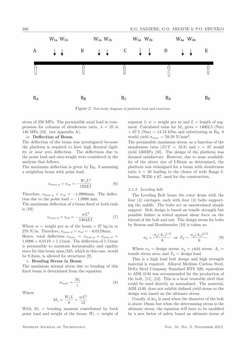
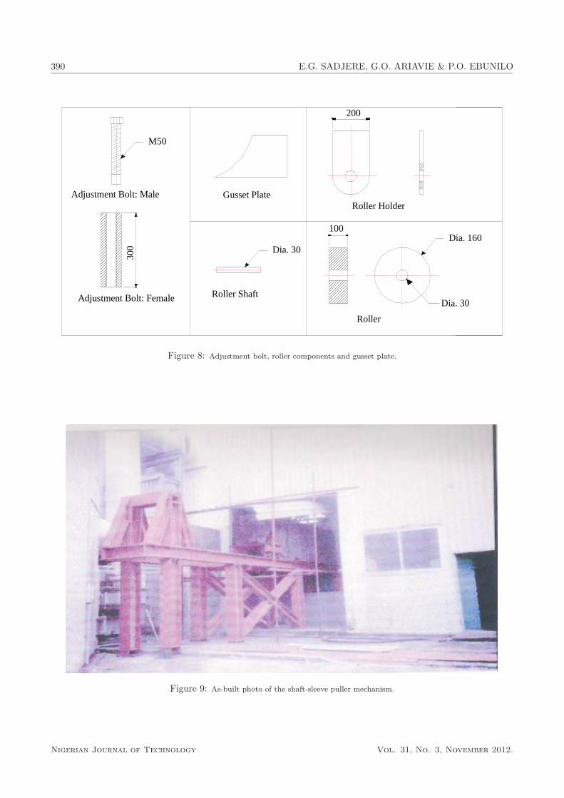
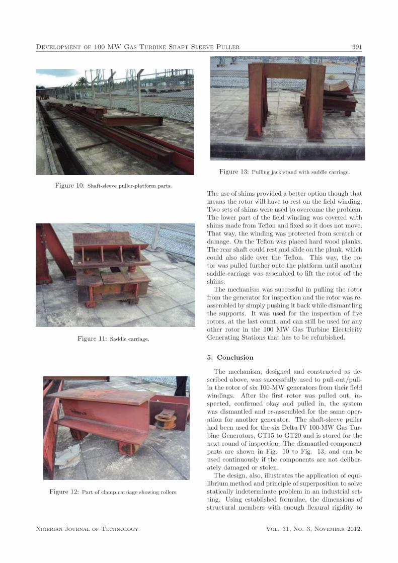
All carriages are fitted with rollers machined fromAISI 4140 or Delta Steel Grade HTS320. One set ofrollers was grooved while the other set was plane. Theroller shafts were also machined while the roller bear-ings were bought off-shelf. Meanwhile, fig. 8 showssome of the elements of the mechanism for connect-ing the members. The scan of the photograph of thefull assembly, taken after the construction, is shownin figs. 9–13.
4. The Operation
The system was assembled at point of use start-ing with the columns and beams to build the plat-form. The frame was next mounted at the far endof the platform for the attachment of the pullingjack (come-along). The first carriage, complete withclamp-assembly, was lifted on to the platform andclamped on to the rotor shaft. The pulling jack isthen connected to the clamp by two cables and thepulling was ready to start. The shaft at the other endor rear shaft of the rotor is relatively long so appre-ciable length of the rotor (about a quarter) was pulledout before the rotor cleared the last bearing. By thistime, the first saddle-carriage was mounted before theshaft cleared the bearing. The carriage is mounted inparts. First, the carriage base was lifted with crane,supported by the personnel, and maneuvered on tothe platform. Next, the saddle was assembled fromopposite sides of the drum and bolted in place. Fi-nally, the bolts were adjusted to move the saddle upto bear on the drum. However, the tension on thecables and the two supports were still not enough tokeep the drum from tilting over at the far end.
This means the design could not fully take care ofthe horizontality of the drum as envisaged. Two pos-sible solutions were considered: (1) to extend the rearshaft or (2) to provide shims in the space betweenthe rotor and the field winding. The first option wasimmediately discarded because there was no space forsuch attachment and the process of producing such at-tachment was going to be expensive and cumbersome.
Nigerian Journal of Technology Vol. 31, No. 3, November 2012.

388 E.G. SADJERE, G.O. ARIAVIE & P.O. EBUNILO
&������
��������'
��������(
�����$����&��
�����������
�%���������
�����������%��������
������&��
��$�������
���� ���
�����
����
'
)
*
(
+
,
'-
./
��$�����������
0
'(
''
')
'*
�� �&��
����������
������������
&������
���������� ����
Figure 4: Details of platform construction.
������������
������&��
�������&��
�������1�����
������
��������%$
&�����
������2��
��������2��
�����3��
���������
&���1������
���������&��
���������4�
'-
''
/.
'
)
(
'-
,
0
+
*
''
Figure 5: Details of saddle carriage construction.
Nigerian Journal of Technology Vol. 31, No. 3, November 2012.
Development of 100 MW Gas Turbine Shaft Sleeve Puller 389
�����������
������&��
�����������
�������&��'-
.
/
)
' ����
����������
�����3��
2������
(
*(--
.
Figure 6: Details of clamp carriage.
'(-
')-
&��5�������&�����������
)--
(--
'(-
6�7�(-���1���
�������&������
')-
&��5&������������
&�������8�������
(0-
'/-
'(-
')-
&����������
'(-
�������������%����
')-
+,
',-
�,-
'/-(,-
Figure 7: Details of connection points.
Nigerian Journal of Technology Vol. 31, No. 3, November 2012.
390 E.G. SADJERE, G.O. ARIAVIE & P.O. EBUNILO
����������� ���� � ������� ���
�� ���� ���
����������� ������ � �� �������
�� ��
�������
���� �
���� �
�!�
���
"��
��
Figure 8: Adjustment bolt, roller components and gusset plate.
�
�
�Figure 9: As-built photo of the shaft-sleeve puller mechanism.
Nigerian Journal of Technology Vol. 31, No. 3, November 2012.
Development of 100 MW Gas Turbine Shaft Sleeve Puller 391�
�Figure 10: Shaft-sleeve puller-platform parts.
�
Figure 11: Saddle carriage.
�
Figure 12: Part of clamp carriage showing rollers.
�
�Figure 13: Pulling jack stand with saddle carriage.
The use of shims provided a better option though thatmeans the rotor will have to rest on the field winding.Two sets of shims were used to overcome the problem.The lower part of the field winding was covered withshims made from Teflon and fixed so it does not move.That way, the winding was protected from scratch ordamage. On the Teflon was placed hard wood planks.The rear shaft could rest and slide on the plank, whichcould also slide over the Teflon. This way, the ro-tor was pulled further onto the platform until anothersaddle-carriage was assembled to lift the rotor off theshims.
The mechanism was successful in pulling the rotorfrom the generator for inspection and the rotor was re-assembled by simply pushing it back while dismantlingthe supports. It was used for the inspection of fiverotors, at the last count, and can still be used for anyother rotor in the 100 MW Gas Turbine ElectricityGenerating Stations that has to be refurbished.
5. Conclusion
The mechanism, designed and constructed as de-scribed above, was successfully used to pull-out/pull-in the rotor of six 100-MW generators from their fieldwindings. After the first rotor was pulled out, in-spected, confirmed okay and pulled in, the systemwas dismantled and re-assembled for the same oper-ation for another generator. The shaft-sleeve pullerhad been used for the six Delta IV 100-MW Gas Tur-bine Generators, GT15 to GT20 and is stored for thenext round of inspection. The dismantled componentparts are shown in Fig. 10 to Fig. 13, and can beused continuously if the components are not deliber-ately damaged or stolen.
The design, also, illustrates the application of equi-librium method and principle of superposition to solvestatically indeterminate problem in an industrial set-ting. Using established formulae, the dimensions ofstructural members with enough flexural rigidity to
Nigerian Journal of Technology Vol. 31, No. 3, November 2012.
392 E.G. SADJERE, G.O. ARIAVIE & P.O. EBUNILO
build a stable frame to withstand the 30 tonne loadwere determined. Material choices were made fromestablished industrial practices and/or manufactured,were possible.
Acknowledgement
1. Voest-Alpine Technical Services, Warri, DesmanLimited Warri, a General Electric Company, forthe assistance in the design and fabrication of theSleeve puller.
2. M. D Ode for his assistance in checking the draw-ings.
References
1. Young, H.D. and Freedman, R.A. Sears and Zeman-
sky University Physics. 11th Ed., Dorling Kindersley,New Delhi, 2006.
2. Jonzactruba. How Does a Gas Turbine Power Plant
Work? The auxiliary Systems. www.brighthub.com
Posted November 18, 2009, accessed May 28, 2012.
3. Theraja, B. L. Fundamentals of Electrical Engineer-
ing and Electronics. S. Chand, New Delhi, India,2004.
4. Kasali, M. A. Delta Power Plant: Operations and
Problems. Orientation Lecture to visitors (unpub-lished).
5. General Electric. GE Reference Documents. www.
site.ge-energy.com Accessed on June 4, 2012.
6. Siswanto, Power Generation Project Experiences,www.sispowergeneration.blogspot.com. PostedJune 21, 2009, accessed on June 4, 2012 .
7. Ugural, A.C. Mechanical Design – An Integrated Ap-
proach, McGraw-Hill, New York, 2004.
8. Shigley, J.E. Mechanical Engineering Design. 3rdEdition, McGraw-Hill, Tokyo Japan, 1977.
9. Dural, S. K. Design of Steel Structures. 2nd Ed, TataMc Graw-Hill Publishing, New Delhi, 2007.
10. Faires, V.M. Design of Machine Elements. 4th Edi-tion Collier Macmillan, New York, 1965.
11. Vereninigte Edelstahl Werke Aktiengesellschaft.VEW Steel Grades. Comparison of World Steel
Grades. Austria, 1997.
12. Delta Steel Company. Manufacturer’s Manual:
Foundry Steel Grade. Un-published, 1988
Appendix
The full properties of the beam S200 × 27 are:
Structural Material: ASTM A-36Overall depth of beam, D = 203 mmMean thickness of compression flange, T = 10.8 mmRadius of gyration about x-x, rx = 82.8 mm
Radius of gyration about y-y, ry = 24.2 mmThickness of web, t = 6.9 mmWith of flange, b = 102 mmCross sectional area, A = 3.5 × 103 mm2
Moment of Inertia, I = 24 × 106 mm4
Section Modulus, z = 236 × 103 mm3
Modulus of Elasticity, E = 200 GPaYield Stress = 250 MPaThe ultimate stress tensile strength of AISI 4140 is980 N/mm2 (MPa).
Nigerian Journal of Technology Vol. 31, No. 3, November 2012.