design of shaft - aligarh muslim university
TRANSCRIPT

DESIGN OF SHAFT
MACHINE DESIGN (BME-602)
UNIT – II(Part I)
Csy: Dr. Shahnawaz Mohsin
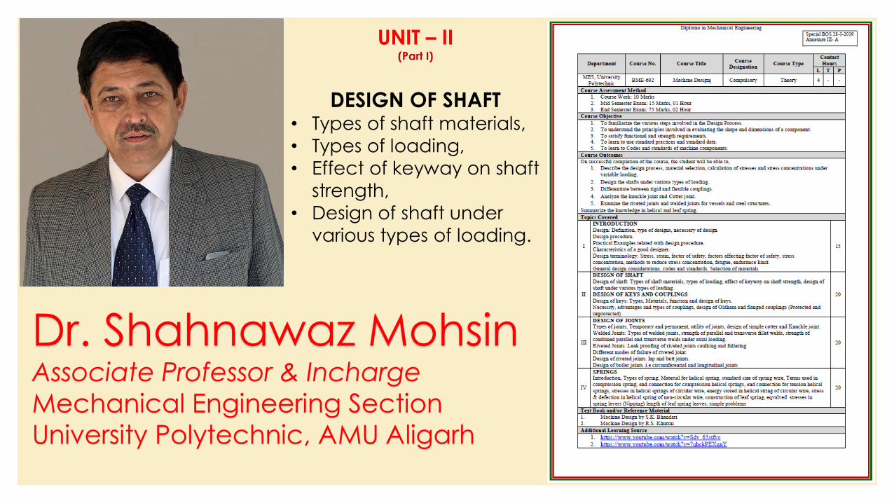
Dr. Shahnawaz MohsinAssociate Professor & Incharge
Mechanical Engineering Section
University Polytechnic, AMU Aligarh
UNIT – II(Part I)
DESIGN OF SHAFT• Types of shaft materials,
• Types of loading,
• Effect of keyway on shaft
strength,
• Design of shaft under
various types of loading.
Design of Shaft
◦ A shaft is a rotating member usually of circular cross-section (solid or hollow), which transmits power and rotational motion.
◦ Machine elements such as gears, pulleys (sheaves), flywheels, clutches, and sprockets are mounted on the shaft and are used to transmit power from the driving device (motor or engine) through a machine.
◦ Press fit, keys, dowel, pins and splines are used to attach these machine elements on the shaft.
◦ The shaft rotates on rolling contact bearings or bush bearings.
◦ Various types of retaining rings, thrust bearings, grooves and steps in the shaft are used to take up axial loads and locate the rotating elements.
◦ Couplings are used to transmit power from drive shaft (e.g., motor) to the driven shaft (e.g. gearbox, wheels).
Csy: Dr. Shahnawaz Mohsin
Talking Points
◦ Shaft ?
◦ Shaft Design
◦ ASME Shaft Equations
◦ Design of Shaft for Torsional Rigidity
◦ Standard Sizes of Shafts
◦ Bending and Torsional Moments
Csy: Dr. Shahnawaz Mohsin
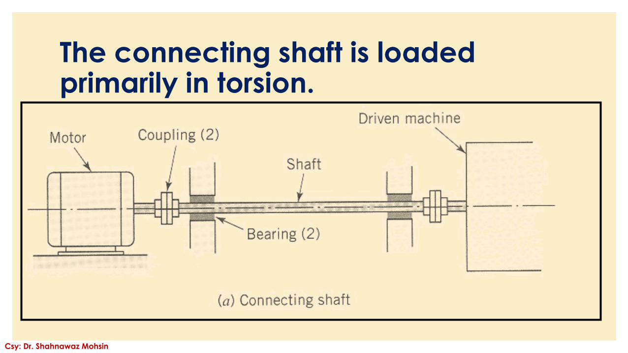
The connecting shaft is loadedprimarily in torsion.
Csy: Dr. Shahnawaz Mohsin
Introduction
◦ A shaft is a rotating machine element which is used to transmit power
from one place to another. The power is delivered to the shaft by some
tangential force and the resultant torque (or twisting moment) set up
within the shaft permits the power to be transferred to various machines
linked up to the shaft.
◦ In order to transfer the power from one shaft to another, the various
members such as pulleys, gears etc., are mounted on it. These
members along with the forces exerted upon them causes the shaft to
bending.
◦ In other words, we may say that a shaft is used for the transmission of
torque and bending moment. The various members are mounted on
the shaft by means of keys or splines.
Csy: Dr. Shahnawaz Mohsin
Notes:
1. The shafts are usually cylindrical, but may be square or cross-
shaped in section. They are solid in cross-section but sometimes
hollow shafts are also used.
2. An axle, though similar in shape to the shaft, is a stationary
machine element and is used for the transmission of bending
moment only. It simply acts as a support for some rotating body
such as hoisting drum, a car wheel or a rope sheave.
3. A spindle is a short shaft that imparts motion either to a cutting
tool (e.g. drill press spindles) or to a work piece (e.g. lathe
spindles).
Csy: Dr. Shahnawaz Mohsin
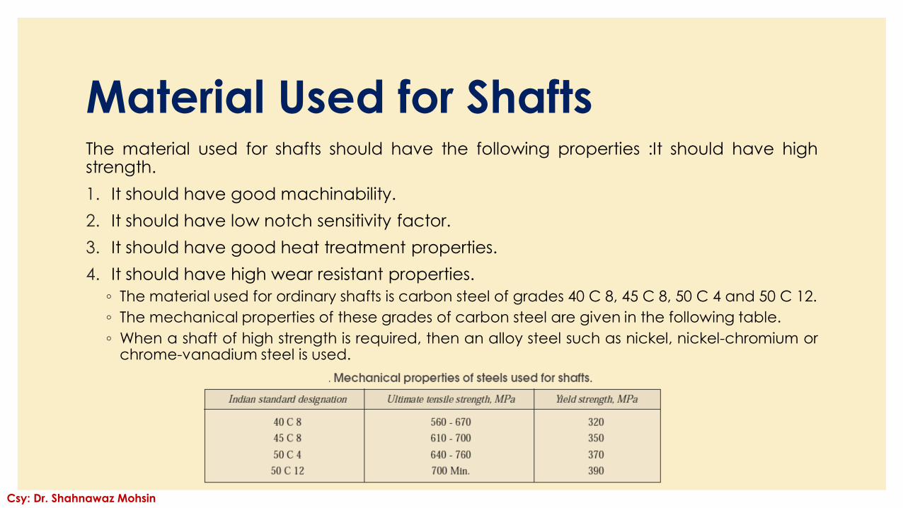
Material Used for ShaftsThe material used for shafts should have the following properties :It should have highstrength.
1. It should have good machinability.
2. It should have low notch sensitivity factor.
3. It should have good heat treatment properties.
4. It should have high wear resistant properties.
◦ The material used for ordinary shafts is carbon steel of grades 40 C 8, 45 C 8, 50 C 4 and 50 C 12.
◦ The mechanical properties of these grades of carbon steel are given in the following table.
◦ When a shaft of high strength is required, then an alloy steel such as nickel, nickel-chromium orchrome-vanadium steel is used.
Csy: Dr. Shahnawaz Mohsin
Manufacturing of Shafts
◦ Shafts are generally manufactured by hot rolling and
finished to size by cold drawing or turning and grinding.
The cold rolled shafts are stronger than hot rolled shafts
but with higher residual stresses.
◦ The residual stresses may cause distortion of the shaft
when it is machined, especially when slots or keyways
are cut. Shafts of larger diameter are usually forged and
turned to size in a lathe.
Csy: Dr. Shahnawaz Mohsin
Types of Shafts
The following two types of shafts are important from the subject
point of view :
1. Transmission shafts. These shafts transmit power between the
source and the machines absorbing power. The counter shafts,
line shafts, over head shafts and all factory shafts are
transmission shafts. Since these shafts carry machine parts such
as pulleys, gears etc., therefore they are subjected to bending
in addition to twisting.
2. Machine shafts. These shafts form an integral part of the
machine itself. The crank shaft is an example of machine shaft.
Standard Sizes of Transmission Shafts
The standard sizes of transmission shafts are :
◦25 mm to 60 mm with 5 mm steps; 60 mm to 110 mm
with 10 mm steps ;
◦110 mm to 140 mm with 15 mm steps ; and
◦140 mm to 500 mm with 20 mm steps.
◦The standard length of the shafts are 5 m, 6 m
and 7 m.
Csy: Dr. Shahnawaz Mohsin
Stresses in Shafts
The following stresses are induced in the shafts :
1. Shear stresses due to the transmission of torque (i.e.
due to torsional load).
2.Bending stresses (tensile or compressive) due to the
forces acting upon machine elements like gears,
pulleys etc. as well as due to the weight of the shaft
itself.
3.Stresses due to combined torsional and bending loads.
Csy: Dr. Shahnawaz Mohsin
Maximum Permissible Working Stresses for Transmission ShaftsAccording to American Society of Mechanical Engineers (ASME) code for the design of transmission shafts,the maximum permissible working stresses in tension or compression may be taken as
(a) 112 MPa for shafts without allowance for keyways.
(b) 84 MPa for shafts with allowance for keyways.
For shafts purchased under definite physical specifications, the permissible tensile stress (σt) may be takenas 60 percent of the elastic limit in tension (σel), but not more than 36 per cent of the ultimate tensilestrength (σu). In other words, the permissible tensile stress,
σt = 0.6 σel or 0.36 σu, whichever is less.
The maximum permissible shear stress may be taken as
(a) 56 MPa for shafts without allowance for key ways.
(b) 42 MPa for shafts with allowance for keyways.
For shafts purchased under definite physical specifications, the permissible shear stress (τ) may be taken as30 per cent of the elastic limit in tension (σel) but not more than 18 percent of the ultimate tensile strength(σu). In other words, the permissible shear stress, τ = 0.3 σel or 0.18 σu, whichever is less.
Csy: Dr. Shahnawaz Mohsin
Design of Shafts
The shafts may be designed on the basis of
1. Strength, and 2. Rigidity and stiffness.
In designing shafts on the basis of strength, the following cases may be
considered :
(a) Shafts subjected to twisting moment or torque only,
(b) Shafts subjected to bending moment only,
(c) Shafts subjected to combined twisting and bending moments, and
(d) Shafts subjected to axial loads in addition to combined torsional and
bending loads.
We shall now discuss the above cases, in detail, in the following slides.
Csy: Dr. Shahnawaz Mohsin
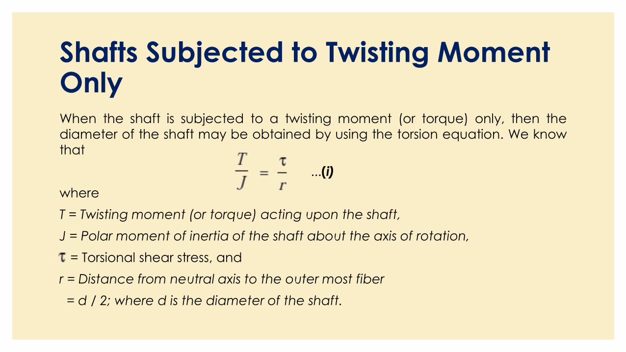
Shafts Subjected to Twisting Moment OnlyWhen the shaft is subjected to a twisting moment (or torque) only, then the
diameter of the shaft may be obtained by using the torsion equation. We know
that
...(i)
where
T = Twisting moment (or torque) acting upon the shaft,
J = Polar moment of inertia of the shaft about the axis of rotation,
= Torsional shear stress, and
r = Distance from neutral axis to the outer most fiber
= d / 2; where d is the diameter of the shaft.
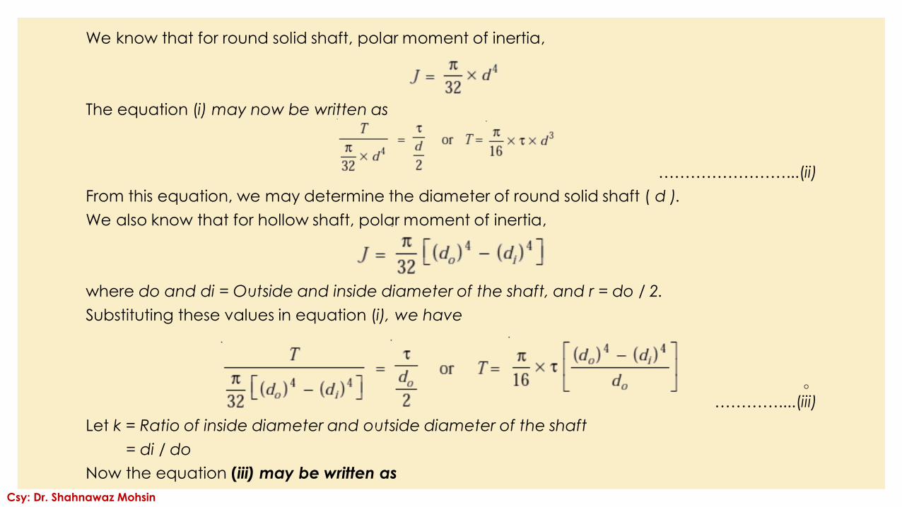
We know that for round solid shaft, polar moment of inertia,
The equation (i) may now be written as
……………………...(ii)
From this equation, we may determine the diameter of round solid shaft ( d ).
We also know that for hollow shaft, polar moment of inertia,
where do and di = Outside and inside diameter of the shaft, and r = do / 2.
Substituting these values in equation (i), we have
◦…………....(iii)
Let k = Ratio of inside diameter and outside diameter of the shaft
= di / do
Now the equation (iii) may be written as
Csy: Dr. Shahnawaz Mohsin
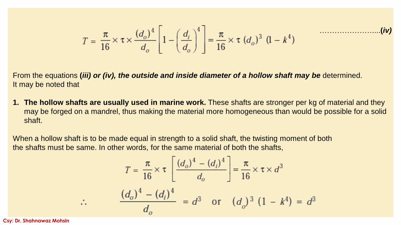
…………………....(iv)
From the equations (iii) or (iv), the outside and inside diameter of a hollow shaft may be determined.
It may be noted that
1. The hollow shafts are usually used in marine work. These shafts are stronger per kg of material and they
may be forged on a mandrel, thus making the material more homogeneous than would be possible for a solid
shaft.
When a hollow shaft is to be made equal in strength to a solid shaft, the twisting moment of both
the shafts must be same. In other words, for the same material of both the shafts,
Csy: Dr. Shahnawaz Mohsin
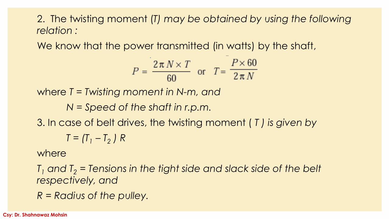
2. The twisting moment (T) may be obtained by using the following
relation :
We know that the power transmitted (in watts) by the shaft,
where T = Twisting moment in N-m, and
N = Speed of the shaft in r.p.m.
3. In case of belt drives, the twisting moment ( T ) is given by
T = (T1 – T2 ) R
where
T1 and T2 = Tensions in the tight side and slack side of the belt
respectively, and
R = Radius of the pulley.
Csy: Dr. Shahnawaz Mohsin
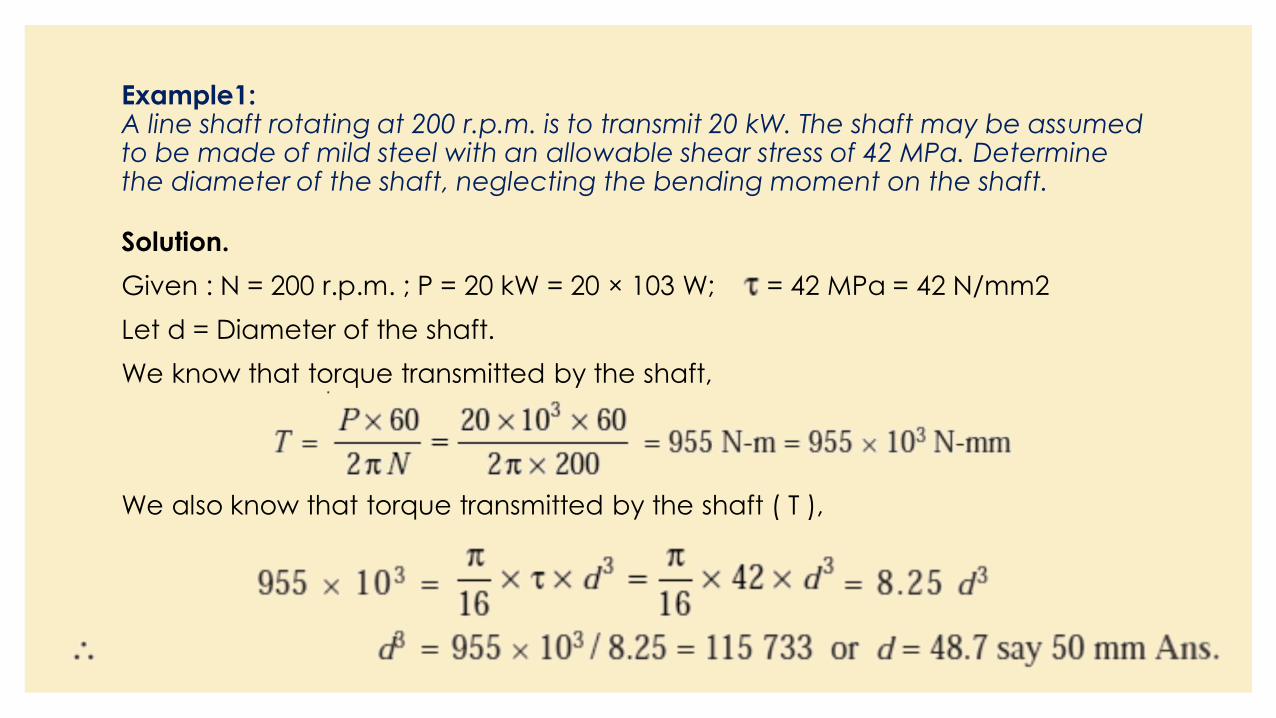
Example1: A line shaft rotating at 200 r.p.m. is to transmit 20 kW. The shaft may be assumed to be made of mild steel with an allowable shear stress of 42 MPa. Determine the diameter of the shaft, neglecting the bending moment on the shaft.
Solution.
Given : N = 200 r.p.m. ; P = 20 kW = 20 × 103 W; = 42 MPa = 42 N/mm2
Let d = Diameter of the shaft.
We know that torque transmitted by the shaft,
We also know that torque transmitted by the shaft ( T ),
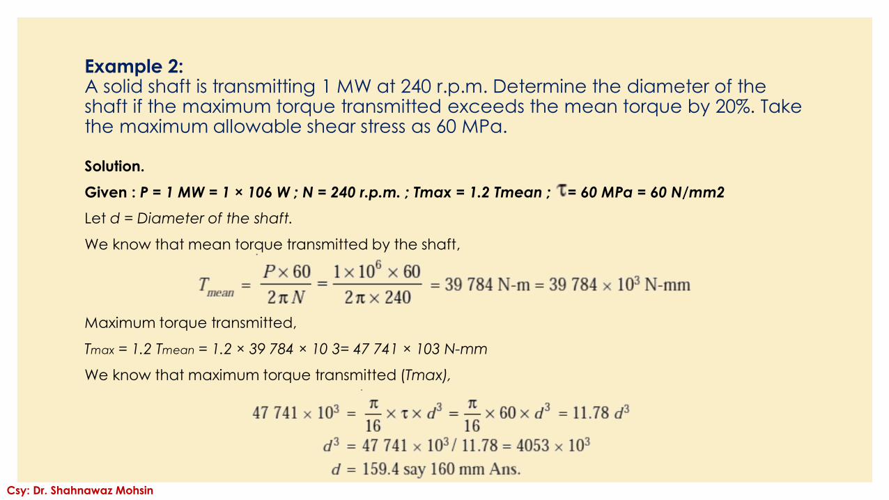
Example 2:A solid shaft is transmitting 1 MW at 240 r.p.m. Determine the diameter of the shaft if the maximum torque transmitted exceeds the mean torque by 20%. Take the maximum allowable shear stress as 60 MPa.
Solution.
Given : P = 1 MW = 1 × 10⁶ W ; N = 240 r.p.m. ; Tmax = 1.2 Tmean ; = 60 MPa = 60 N/mm2
Let d = Diameter of the shaft.
We know that mean torque transmitted by the shaft,
Maximum torque transmitted,
Tmax = 1.2 Tmean = 1.2 × 39 784 × 10 3= 47 741 × 103 N-mm
We know that maximum torque transmitted (Tmax),
Csy: Dr. Shahnawaz Mohsin
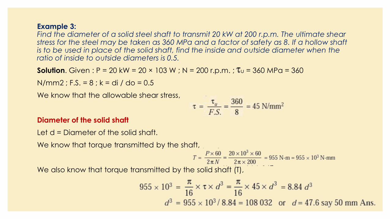
Example 3:Find the diameter of a solid steel shaft to transmit 20 kW at 200 r.p.m. The ultimate shear stress for the steel may be taken as 360 MPa and a factor of safety as 8. If a hollow shaft is to be used in place of the solid shaft, find the inside and outside diameter when the ratio of inside to outside diameters is 0.5.
Solution. Given : P = 20 kW = 20 × 103 W ; N = 200 r.p.m. ; u = 360 MPa = 360
N/mm2 ; F.S. = 8 ; k = di / do = 0.5
We know that the allowable shear stress,
Diameter of the solid shaft
Let d = Diameter of the solid shaft.
We know that torque transmitted by the shaft,
We also know that torque transmitted by the solid shaft (T),
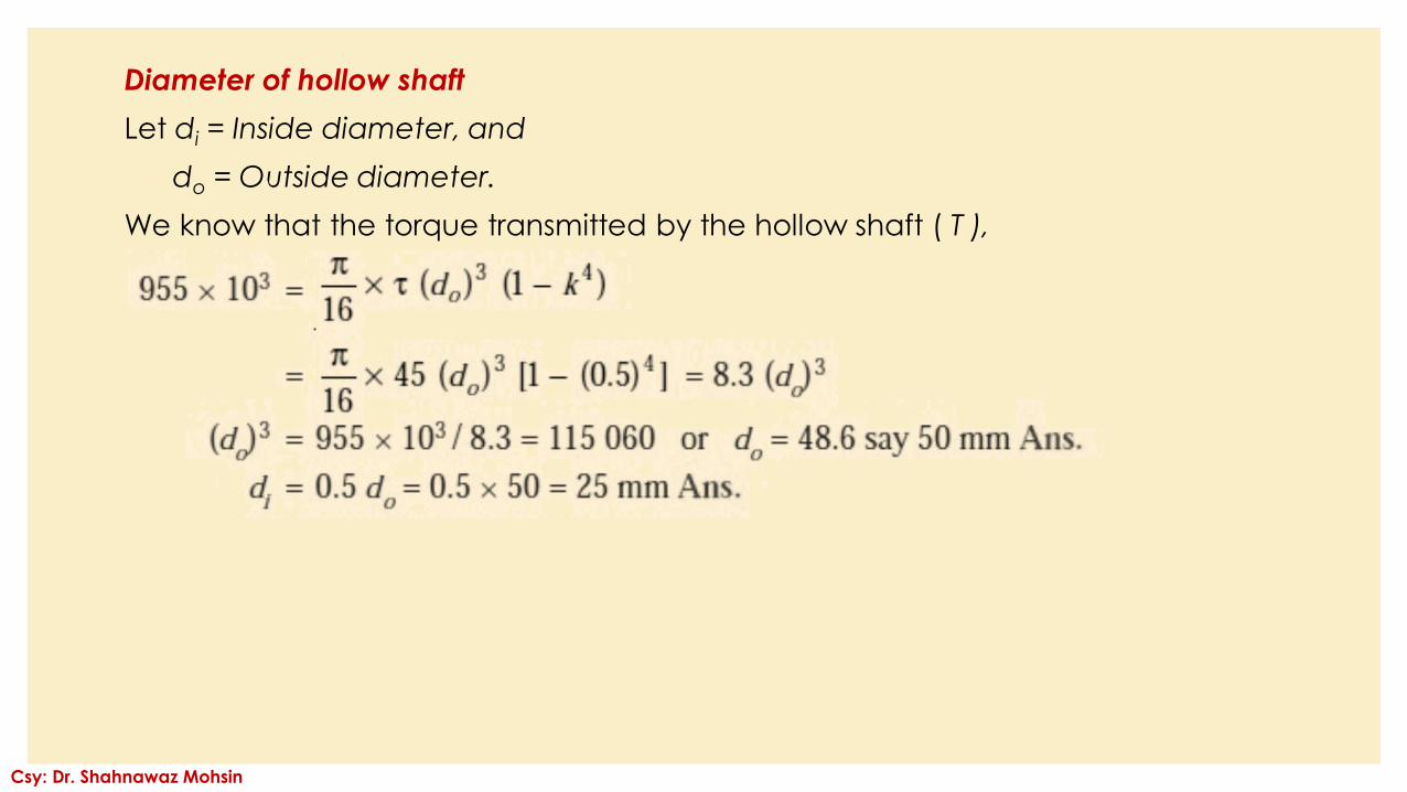
Diameter of hollow shaft
Let di = Inside diameter, and
do = Outside diameter.
We know that the torque transmitted by the hollow shaft ( T ),
Csy: Dr. Shahnawaz Mohsin
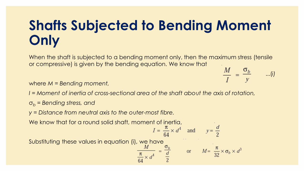
Shafts Subjected to Bending Moment OnlyWhen the shaft is subjected to a bending moment only, then the maximum stress (tensile
or compressive) is given by the bending equation. We know that
...(i)
where M = Bending moment,
I = Moment of inertia of cross-sectional area of the shaft about the axis of rotation,
σb = Bending stress, and
y = Distance from neutral axis to the outer-most fibre.
We know that for a round solid shaft, moment of inertia,
Substituting these values in equation (i), we have
From this equation, diameter of the solid shaft (d) may be
obtained.
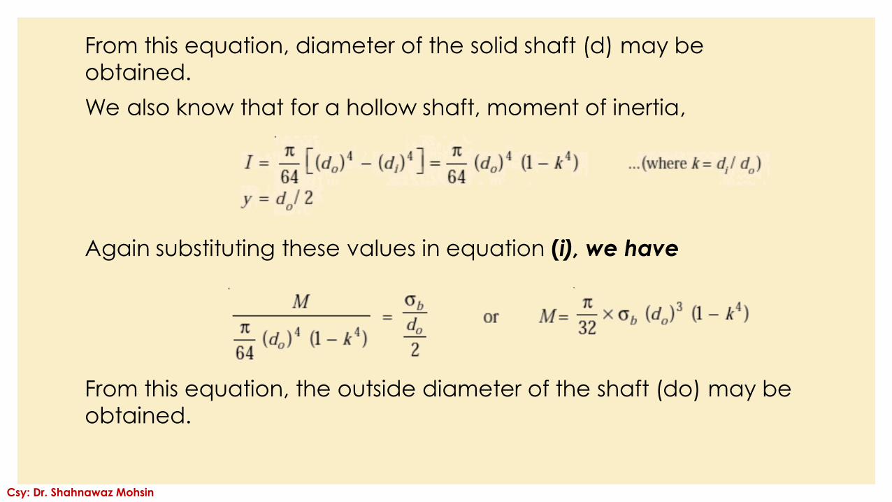
We also know that for a hollow shaft, moment of inertia,
Again substituting these values in equation (i), we have
From this equation, the outside diameter of the shaft (do) may be
obtained.
Csy: Dr. Shahnawaz Mohsin
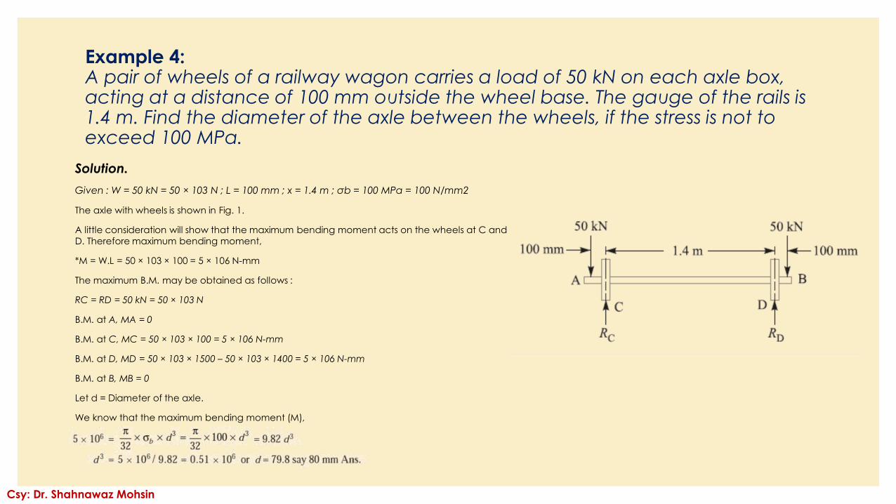
Example 4:A pair of wheels of a railway wagon carries a load of 50 kN on each axle box, acting at a distance of 100 mm outside the wheel base. The gauge of the rails is 1.4 m. Find the diameter of the axle between the wheels, if the stress is not to exceed 100 MPa.
Solution.
Given : W = 50 kN = 50 × 103 N ; L = 100 mm ; x = 1.4 m ; σb = 100 MPa = 100 N/mm2
The axle with wheels is shown in Fig. 1.
A little consideration will show that the maximum bending moment acts on the wheels at C and
D. Therefore maximum bending moment,
*M = W.L = 50 × 103 × 100 = 5 × 10⁶ N-mm
The maximum B.M. may be obtained as follows :
RC = RD = 50 kN = 50 × 103 N
B.M. at A, MA = 0
B.M. at C, MC = 50 × 103 × 100 = 5 × 10⁶ N-mm
B.M. at D, MD = 50 × 103 × 1500 – 50 × 103 × 1400 = 5 × 10⁶ N-mm
B.M. at B, MB = 0
Let d = Diameter of the axle.
We know that the maximum bending moment (M),
Csy: Dr. Shahnawaz Mohsin
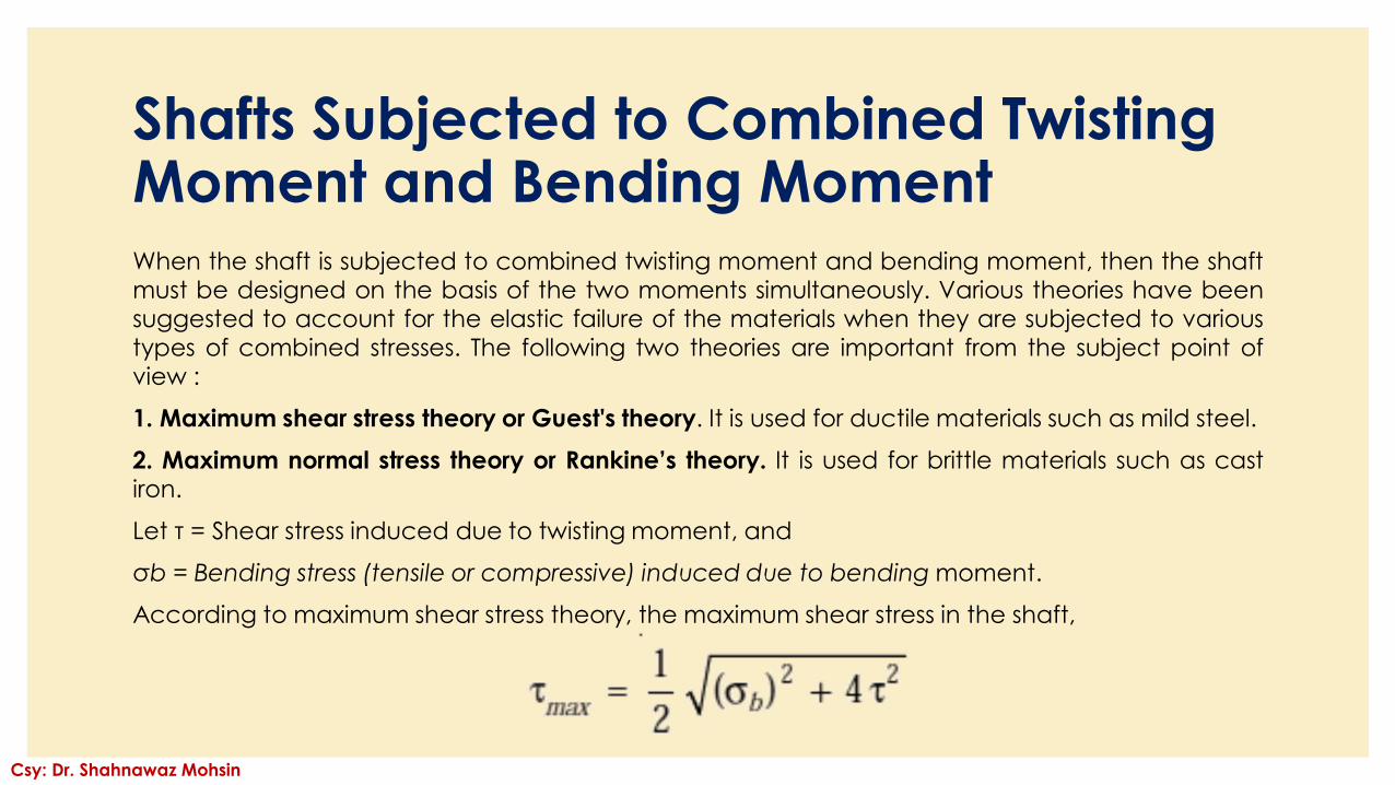
Shafts Subjected to Combined Twisting Moment and Bending MomentWhen the shaft is subjected to combined twisting moment and bending moment, then the shaftmust be designed on the basis of the two moments simultaneously. Various theories have beensuggested to account for the elastic failure of the materials when they are subjected to varioustypes of combined stresses. The following two theories are important from the subject point ofview :
1. Maximum shear stress theory or Guest's theory. It is used for ductile materials such as mild steel.
2. Maximum normal stress theory or Rankine’s theory. It is used for brittle materials such as castiron.
Let τ = Shear stress induced due to twisting moment, and
σb = Bending stress (tensile or compressive) induced due to bending moment.
According to maximum shear stress theory, the maximum shear stress in the shaft,
Csy: Dr. Shahnawaz Mohsin
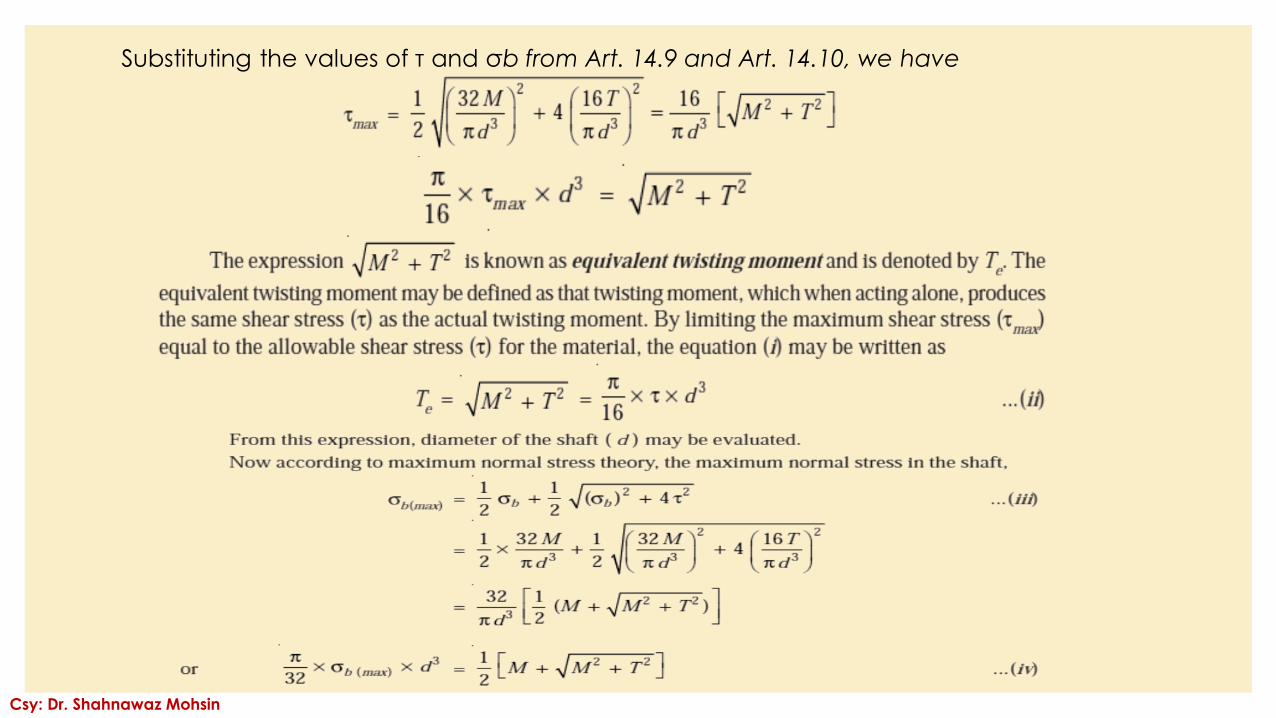
Substituting the values of τ and σb from Art. 14.9 and Art. 14.10, we have
Csy: Dr. Shahnawaz Mohsin
Csy: Dr. Shahnawaz Mohsin
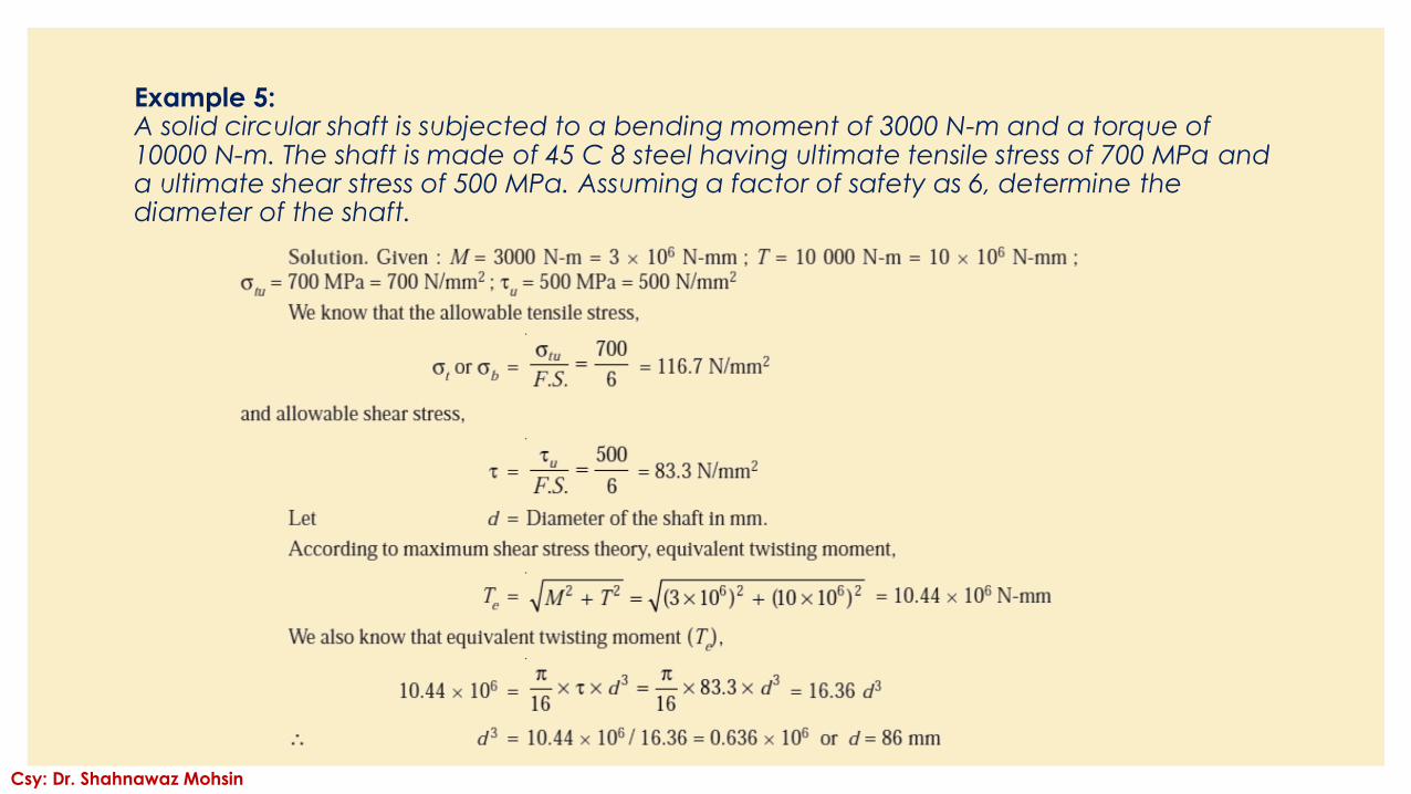
Example 5:A solid circular shaft is subjected to a bending moment of 3000 N-m and a torque of 10000 N-m. The shaft is made of 45 C 8 steel having ultimate tensile stress of 700 MPa and a ultimate shear stress of 500 MPa. Assuming a factor of safety as 6, determine the diameter of the shaft.
Csy: Dr. Shahnawaz Mohsin
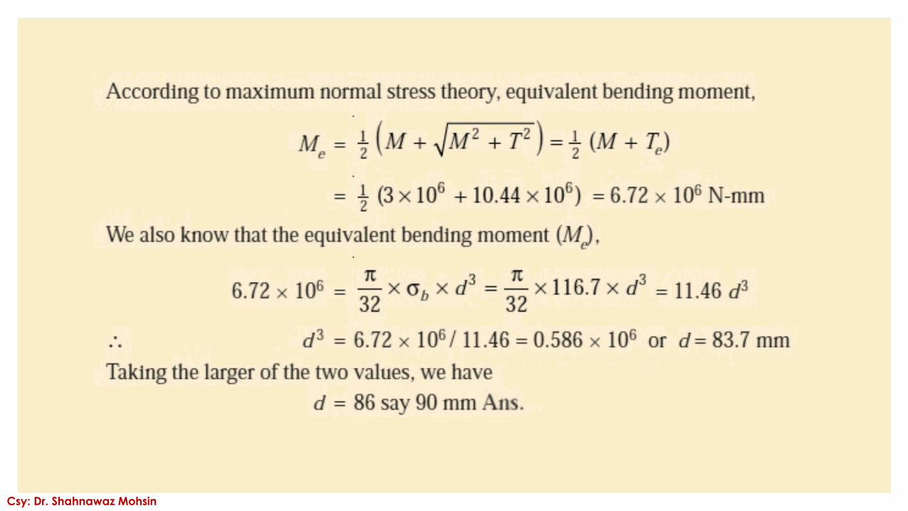
Csy: Dr. Shahnawaz Mohsin
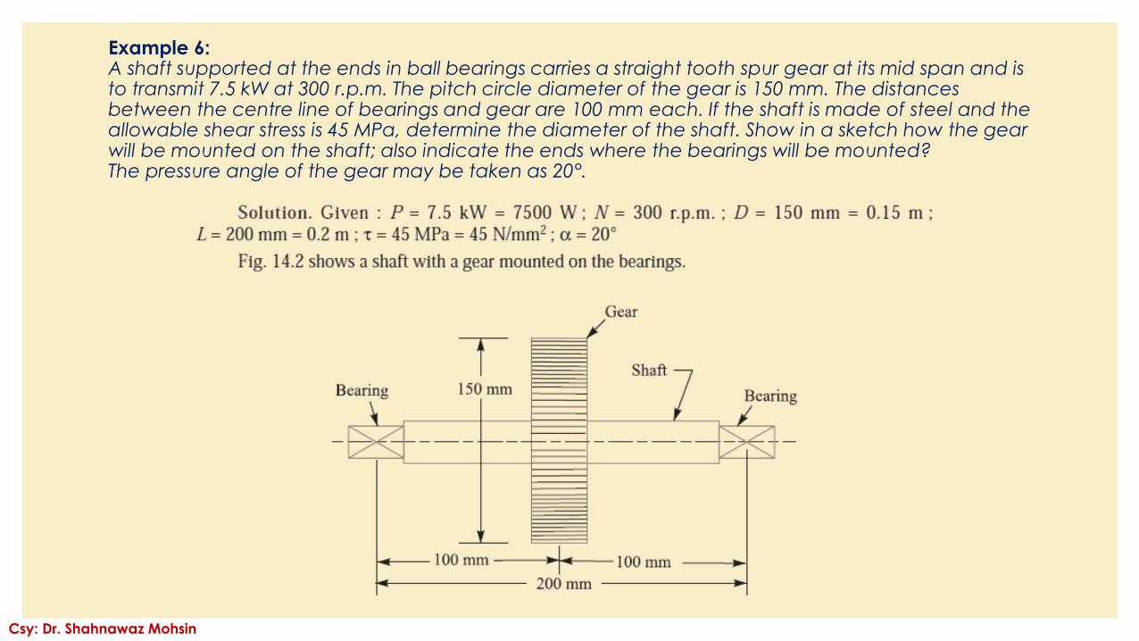
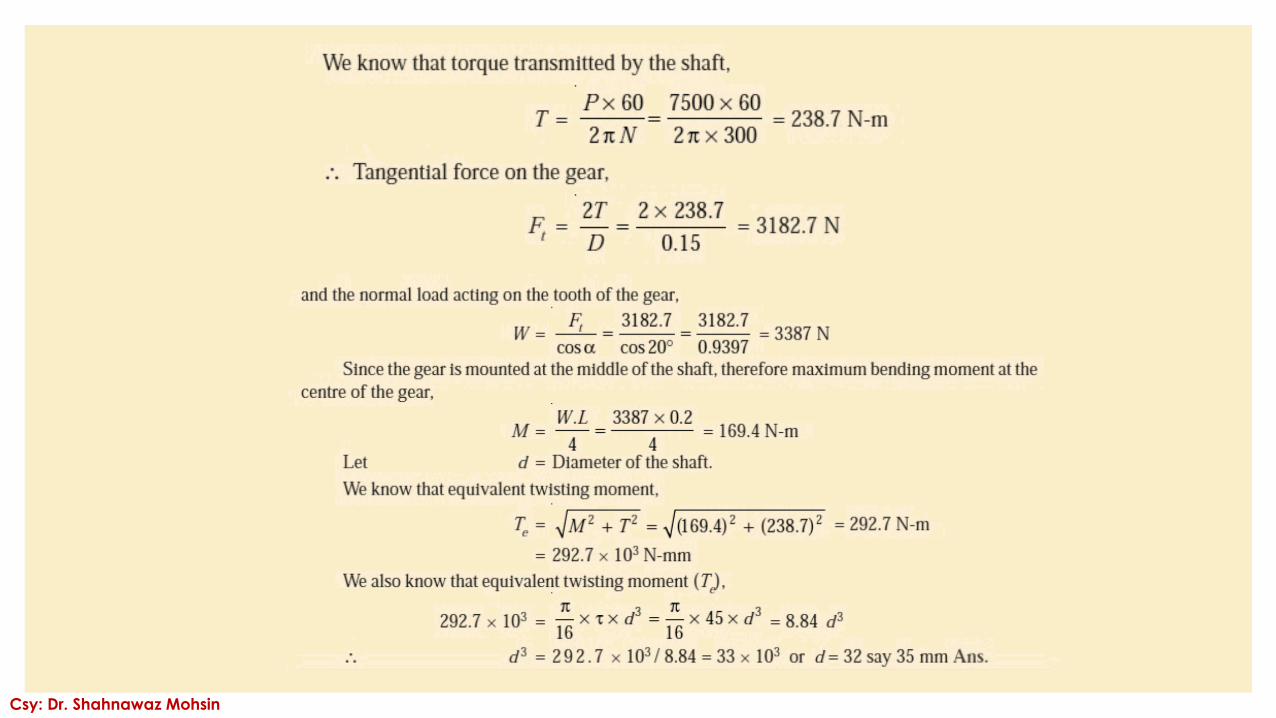
Example 6:A shaft supported at the ends in ball bearings carries a straight tooth spur gear at its mid span and is to transmit 7.5 kW at 300 r.p.m. The pitch circle diameter of the gear is 150 mm. The distances between the centre line of bearings and gear are 100 mm each. If the shaft is made of steel and the allowable shear stress is 45 MPa, determine the diameter of the shaft. Show in a sketch how the gear will be mounted on the shaft; also indicate the ends where the bearings will be mounted?The pressure angle of the gear may be taken as 20°.
Csy: Dr. Shahnawaz Mohsin
Csy: Dr. Shahnawaz Mohsin
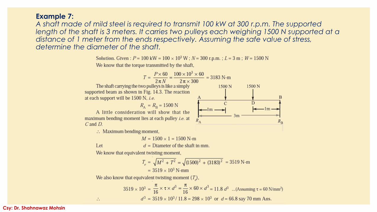
Example 7:A shaft made of mild steel is required to transmit 100 kW at 300 r.p.m. The supported length of the shaft is 3 meters. It carries two pulleys each weighing 1500 N supported at a distance of 1 meter from the ends respectively. Assuming the safe value of stress, determine the diameter of the shaft.
Csy: Dr. Shahnawaz Mohsin
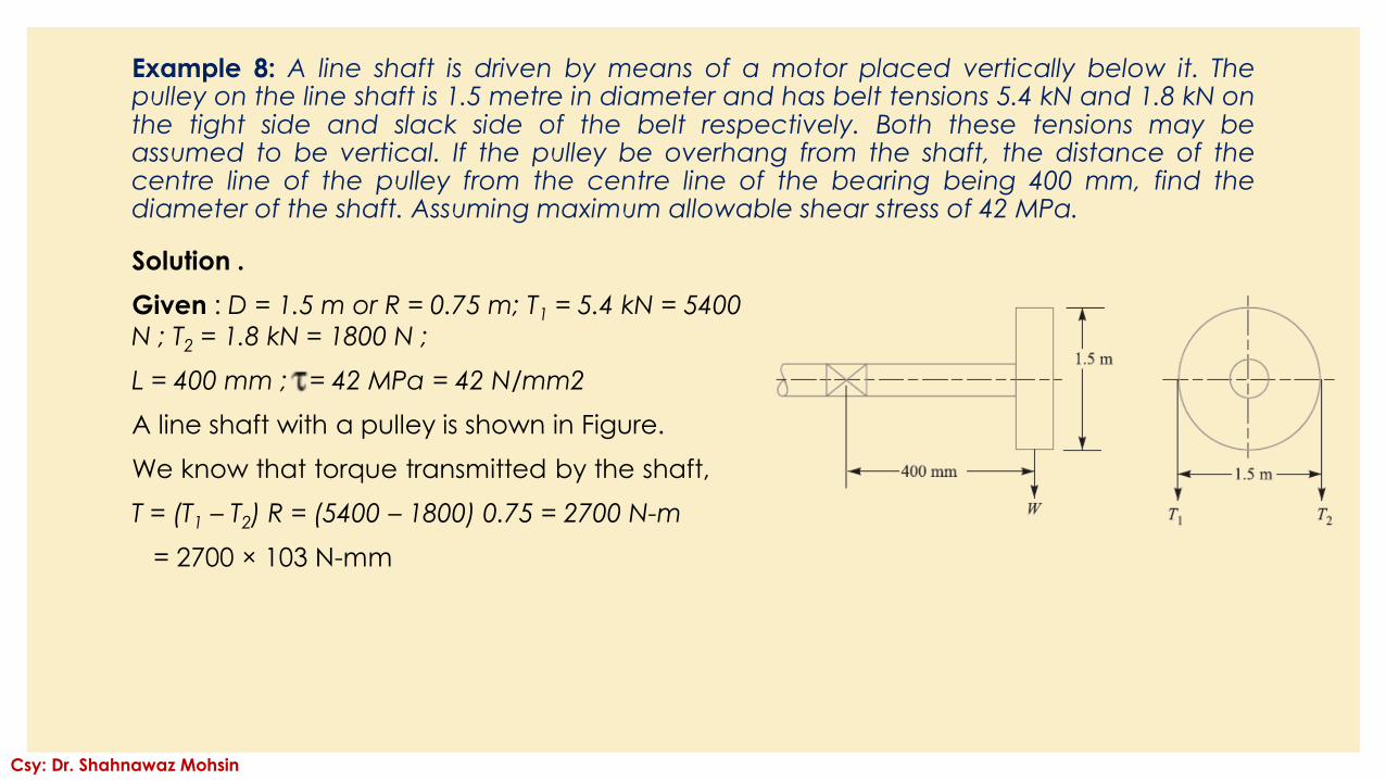
Example 8: A line shaft is driven by means of a motor placed vertically below it. Thepulley on the line shaft is 1.5 metre in diameter and has belt tensions 5.4 kN and 1.8 kN onthe tight side and slack side of the belt respectively. Both these tensions may beassumed to be vertical. If the pulley be overhang from the shaft, the distance of thecentre line of the pulley from the centre line of the bearing being 400 mm, find thediameter of the shaft. Assuming maximum allowable shear stress of 42 MPa.
Solution .
Given : D = 1.5 m or R = 0.75 m; T1 = 5.4 kN = 5400
N ; T2 = 1.8 kN = 1800 N ;
L = 400 mm ; = 42 MPa = 42 N/mm2
A line shaft with a pulley is shown in Figure.
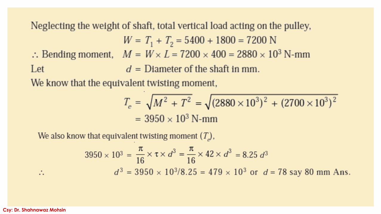
We know that torque transmitted by the shaft,
T = (T1 – T2) R = (5400 – 1800) 0.75 = 2700 N-m
= 2700 × 103 N-mm
Csy: Dr. Shahnawaz Mohsin
Csy: Dr. Shahnawaz Mohsin
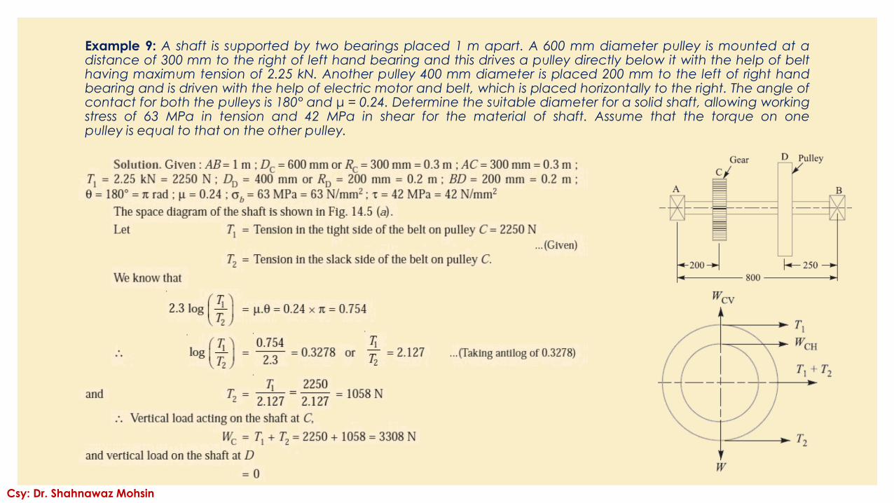
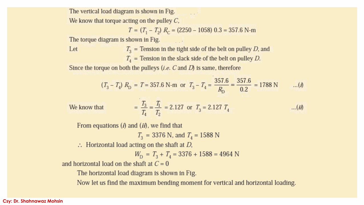
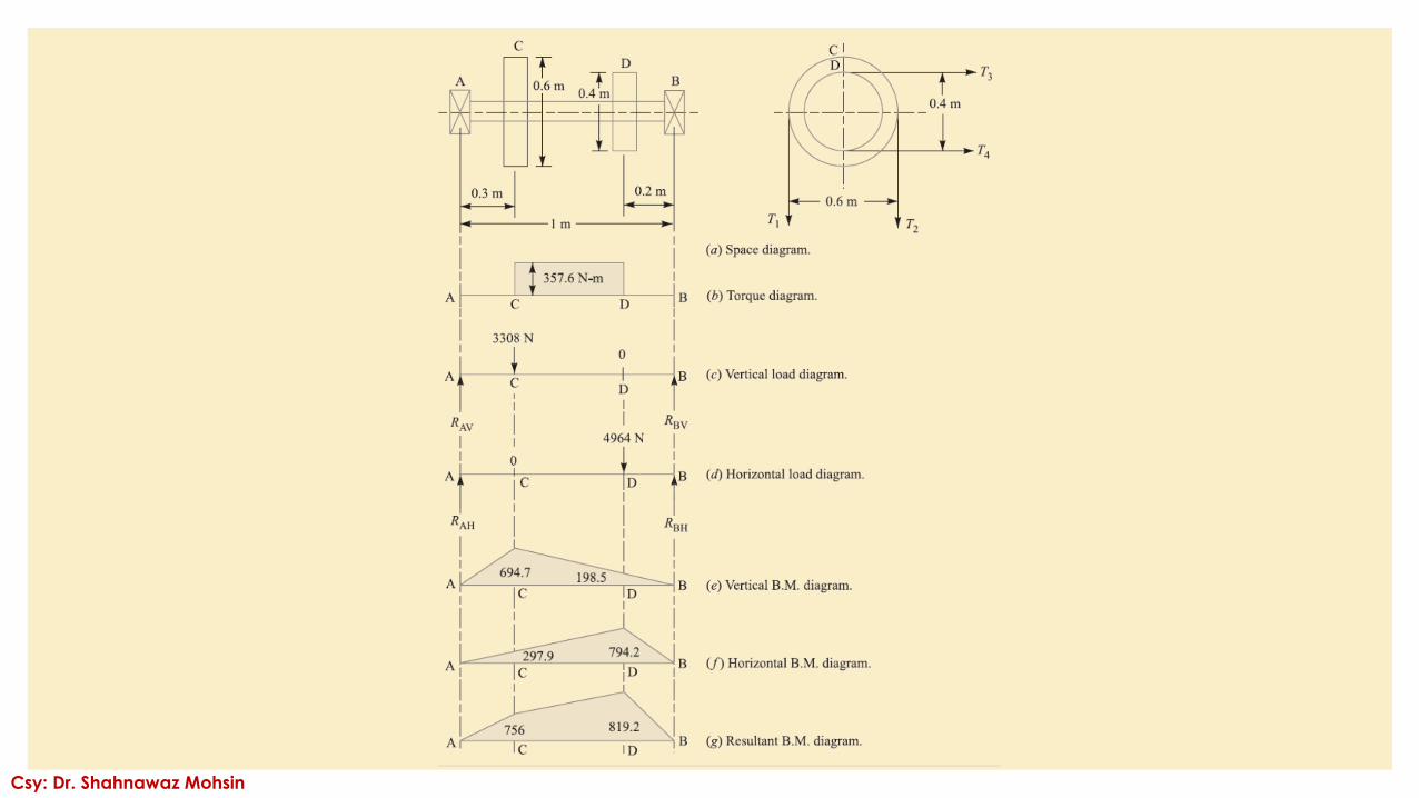
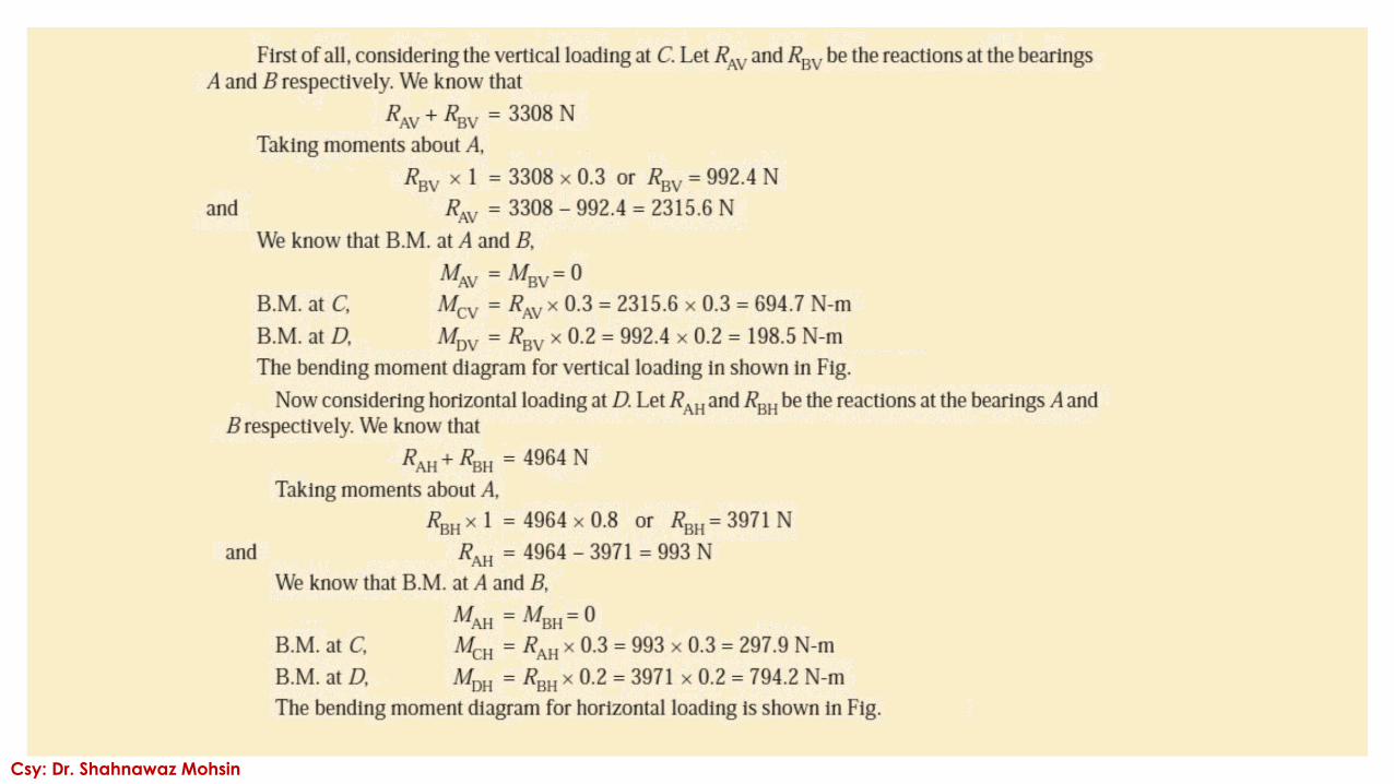
Example 9: A shaft is supported by two bearings placed 1 m apart. A 600 mm diameter pulley is mounted at adistance of 300 mm to the right of left hand bearing and this drives a pulley directly below it with the help of belthaving maximum tension of 2.25 kN. Another pulley 400 mm diameter is placed 200 mm to the left of right handbearing and is driven with the help of electric motor and belt, which is placed horizontally to the right. The angle ofcontact for both the pulleys is 180° and μ = 0.24. Determine the suitable diameter for a solid shaft, allowing workingstress of 63 MPa in tension and 42 MPa in shear for the material of shaft. Assume that the torque on onepulley is equal to that on the other pulley.
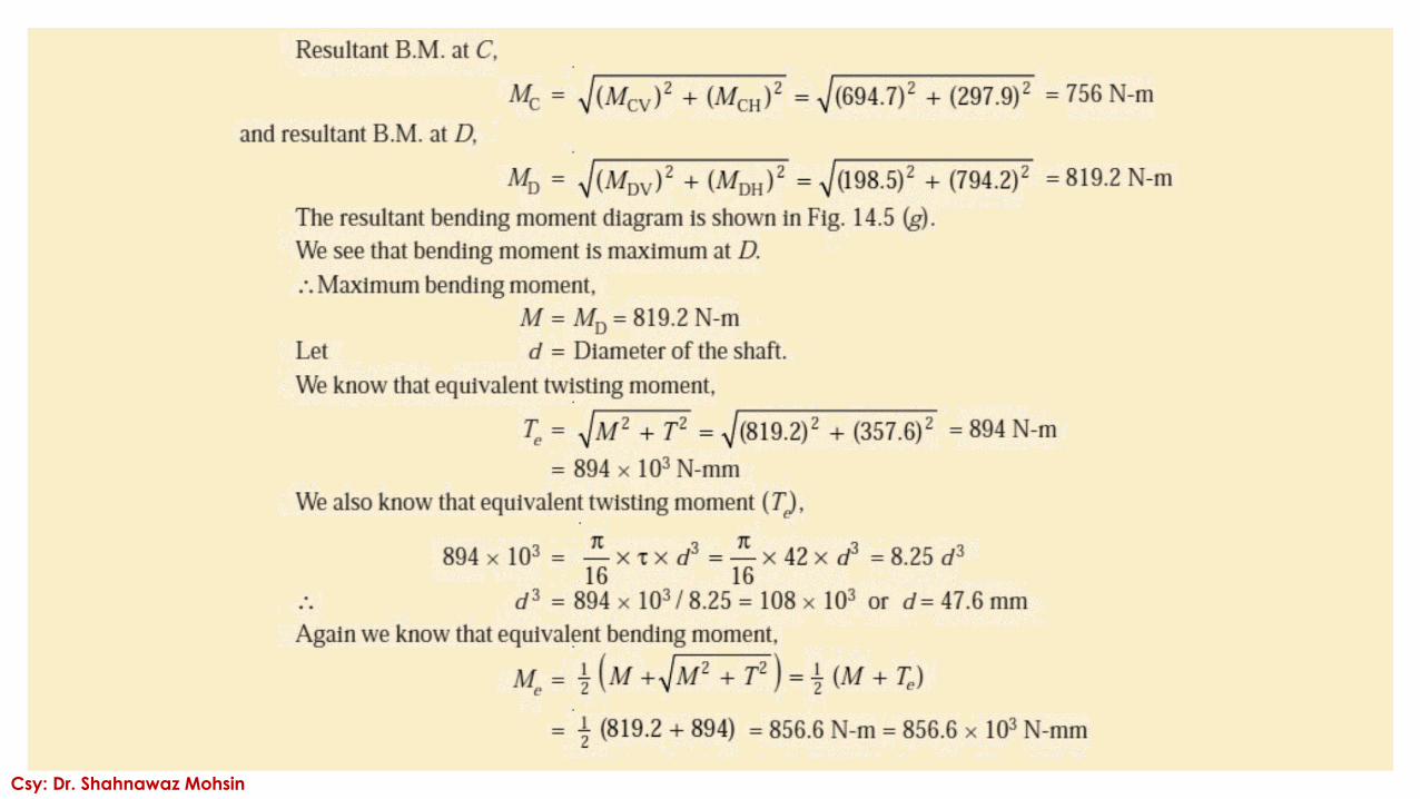
Csy: Dr. Shahnawaz Mohsin
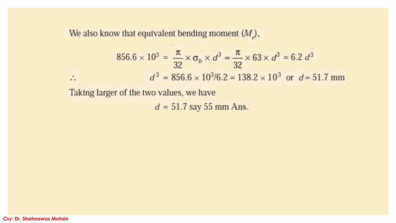
Csy: Dr. Shahnawaz Mohsin
Csy: Dr. Shahnawaz Mohsin
Csy: Dr. Shahnawaz Mohsin
Csy: Dr. Shahnawaz Mohsin
Csy: Dr. Shahnawaz Mohsin
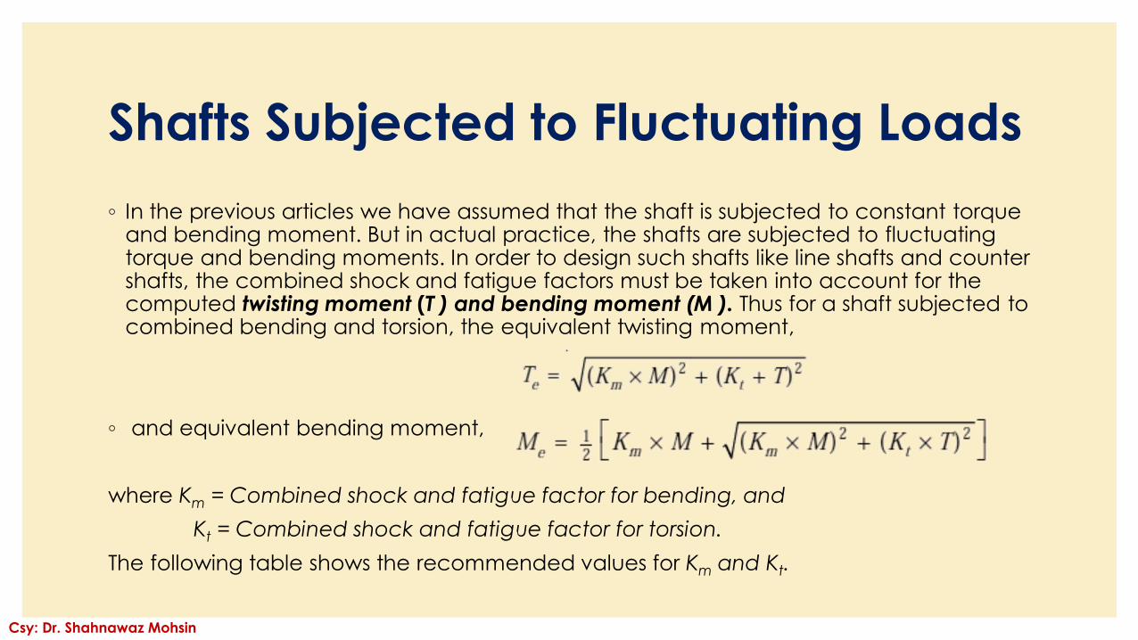
Shafts Subjected to Fluctuating Loads
◦ In the previous articles we have assumed that the shaft is subjected to constant torque and bending moment. But in actual practice, the shafts are subjected to fluctuating torque and bending moments. In order to design such shafts like line shafts and counter shafts, the combined shock and fatigue factors must be taken into account for the computed twisting moment (T ) and bending moment (M ). Thus for a shaft subjected to combined bending and torsion, the equivalent twisting moment,
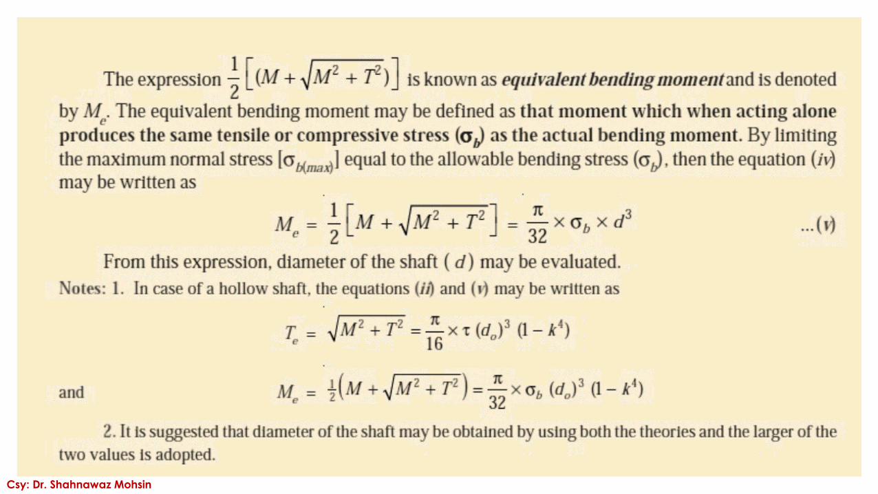
◦ and equivalent bending moment,
where Km = Combined shock and fatigue factor for bending, and
Kt = Combined shock and fatigue factor for torsion.
The following table shows the recommended values for Km and Kt.
Csy: Dr. Shahnawaz Mohsin
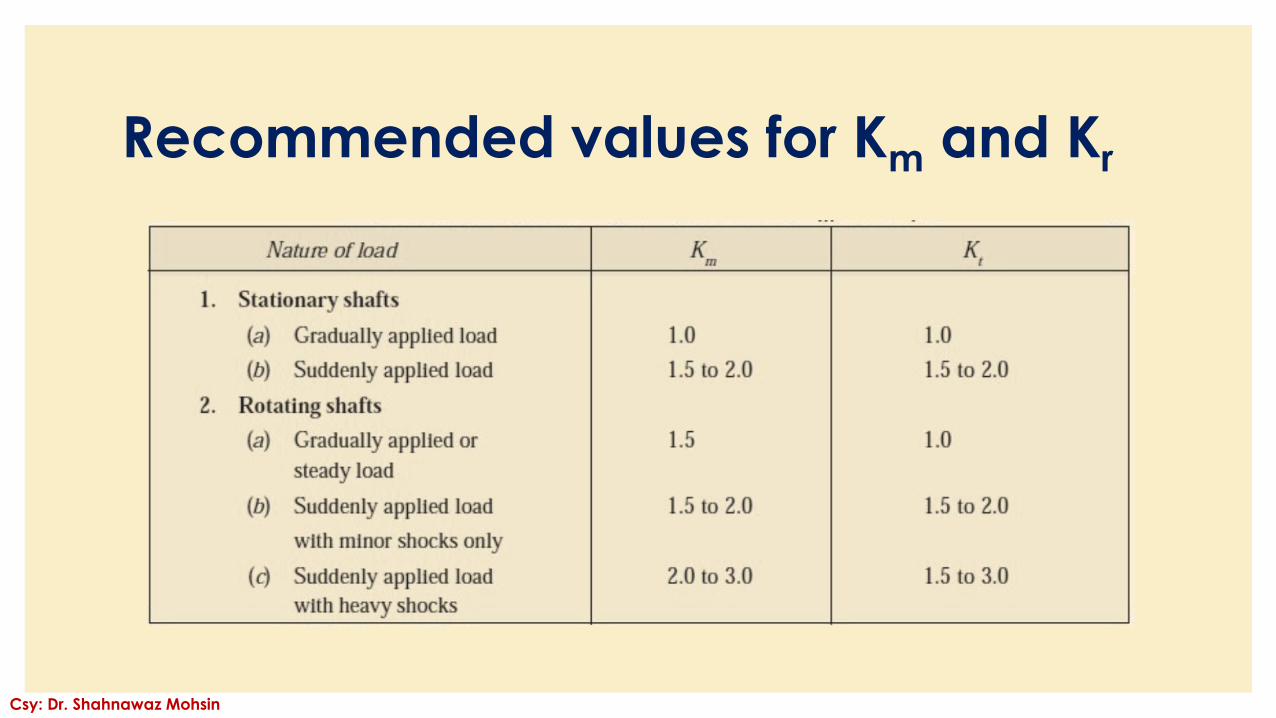
Recommended values for Km and Kr
Csy: Dr. Shahnawaz Mohsin
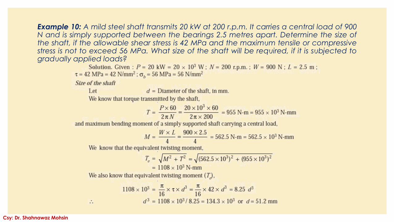
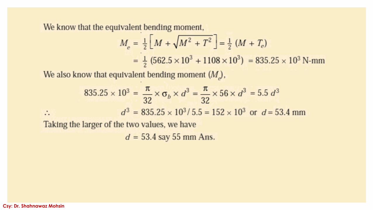
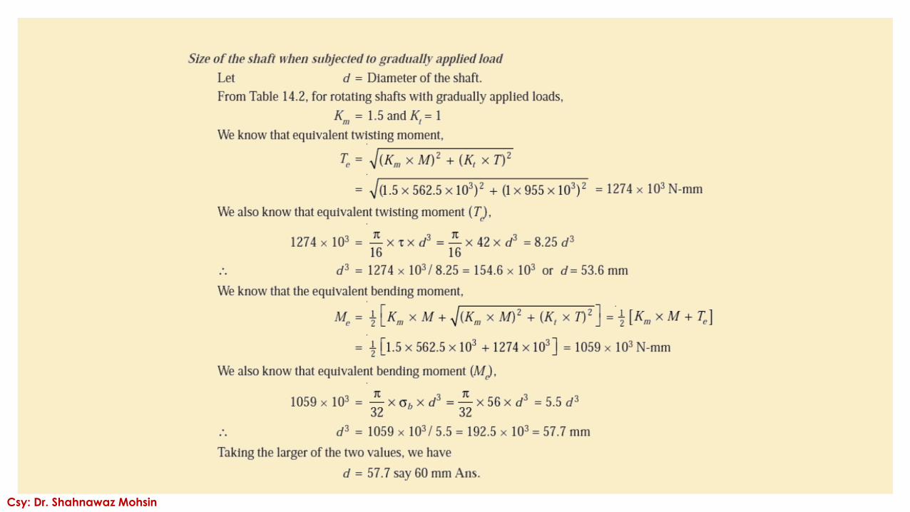
Example 10: A mild steel shaft transmits 20 kW at 200 r.p.m. It carries a central load of 900N and is simply supported between the bearings 2.5 metres apart. Determine the size ofthe shaft, if the allowable shear stress is 42 MPa and the maximum tensile or compressivestress is not to exceed 56 MPa. What size of the shaft will be required, if it is subjected togradually applied loads?
Csy: Dr. Shahnawaz Mohsin
Csy: Dr. Shahnawaz Mohsin
Csy: Dr. Shahnawaz Mohsin
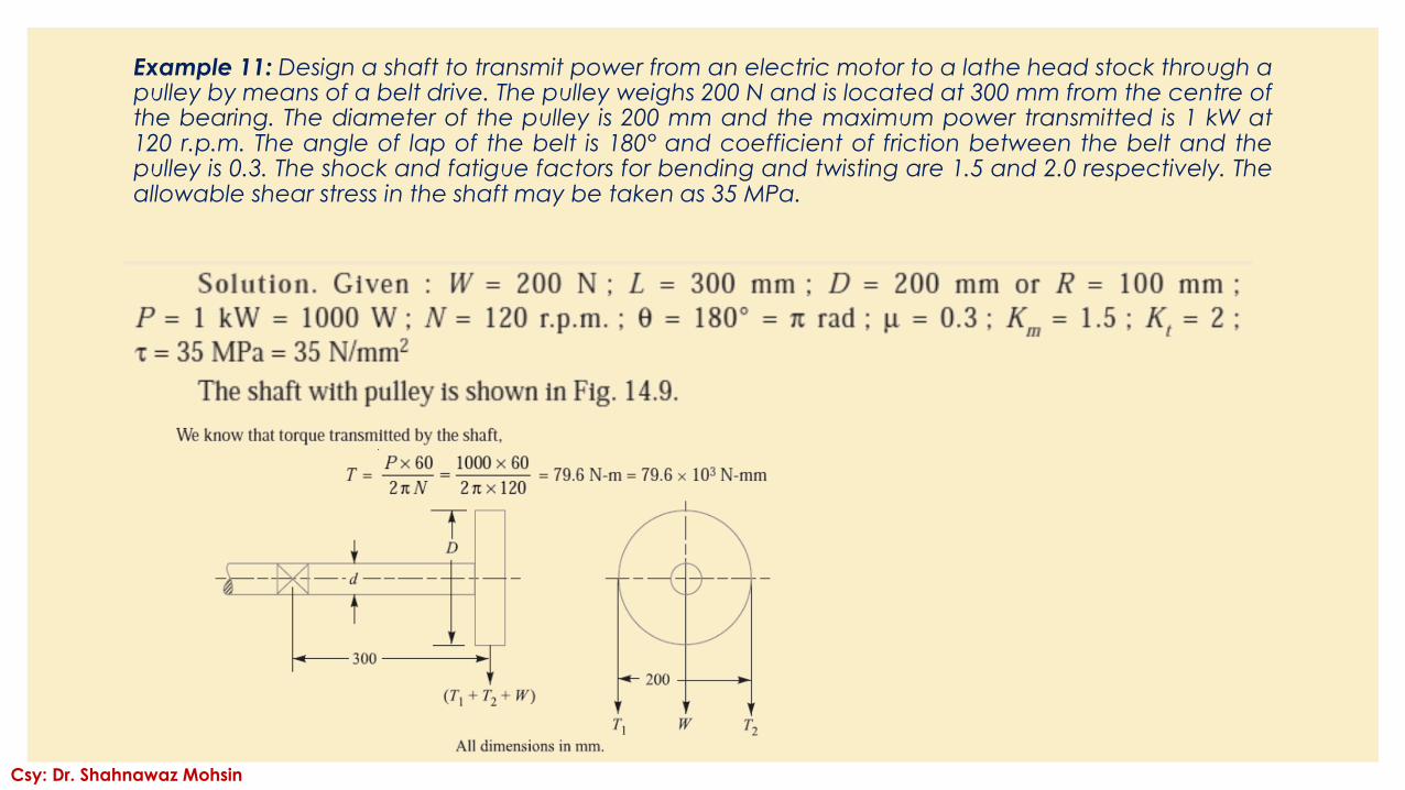
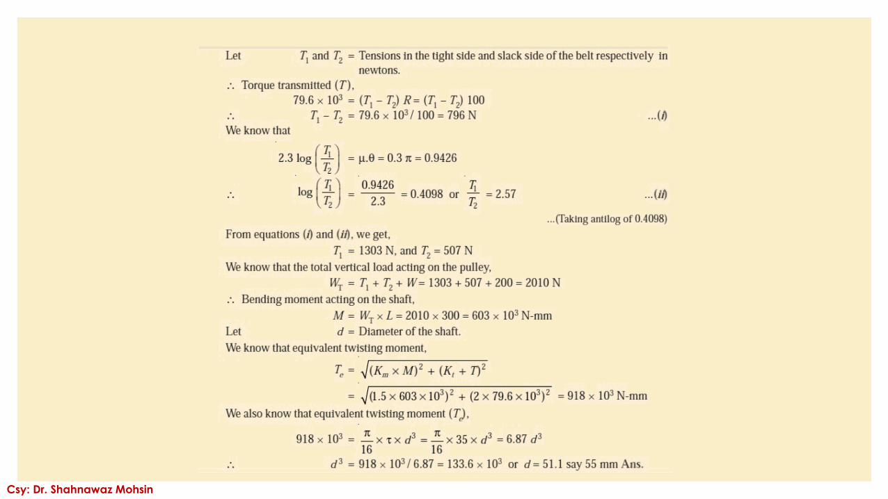
Example 11: Design a shaft to transmit power from an electric motor to a lathe head stock through apulley by means of a belt drive. The pulley weighs 200 N and is located at 300 mm from the centre ofthe bearing. The diameter of the pulley is 200 mm and the maximum power transmitted is 1 kW at120 r.p.m. The angle of lap of the belt is 180° and coefficient of friction between the belt and thepulley is 0.3. The shock and fatigue factors for bending and twisting are 1.5 and 2.0 respectively. Theallowable shear stress in the shaft may be taken as 35 MPa.
Csy: Dr. Shahnawaz Mohsin
Csy: Dr. Shahnawaz Mohsin
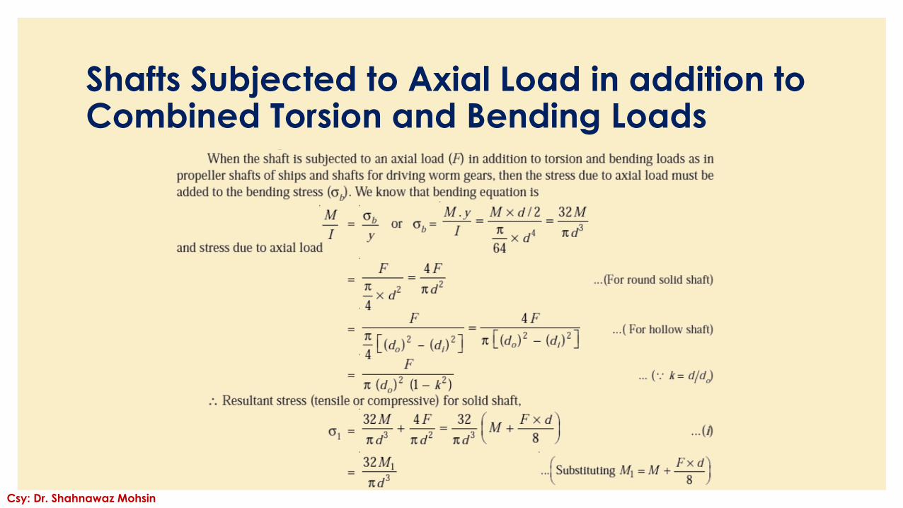
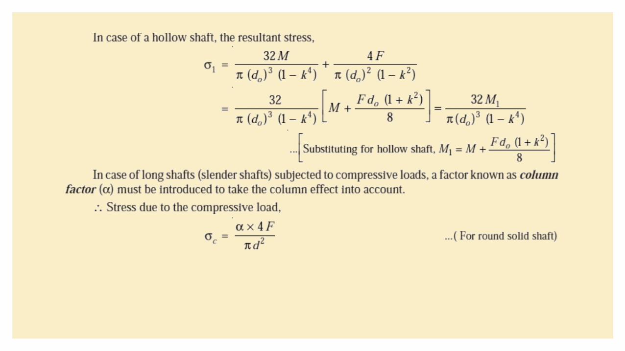
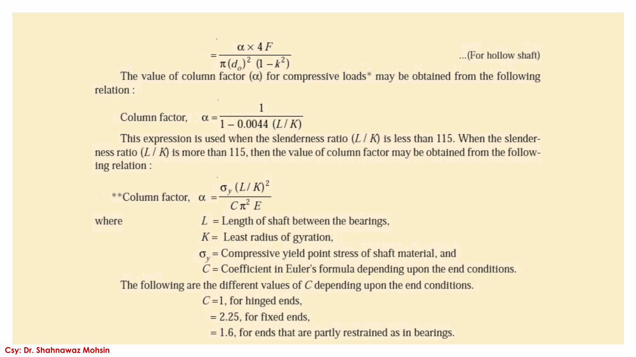
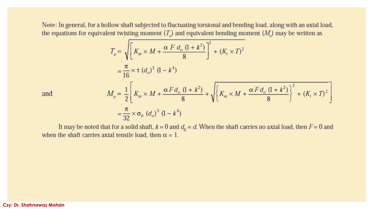
Shafts Subjected to Axial Load in addition to Combined Torsion and Bending Loads
Csy: Dr. Shahnawaz Mohsin
Csy: Dr. Shahnawaz Mohsin
Csy: Dr. Shahnawaz Mohsin
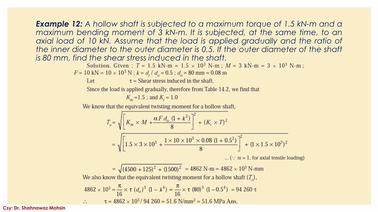
Example 12: A hollow shaft is subjected to a maximum torque of 1.5 kN-m and amaximum bending moment of 3 kN-m. It is subjected, at the same time, to anaxial load of 10 kN. Assume that the load is applied gradually and the ratio ofthe inner diameter to the outer diameter is 0.5. If the outer diameter of the shaftis 80 mm, find the shear stress induced in the shaft.
Csy: Dr. Shahnawaz Mohsin
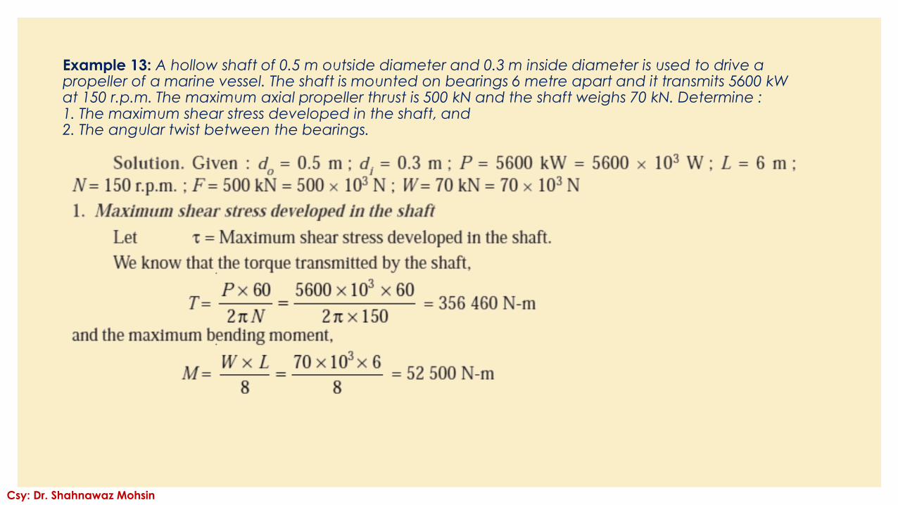
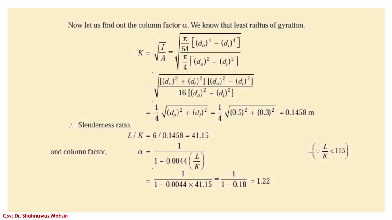
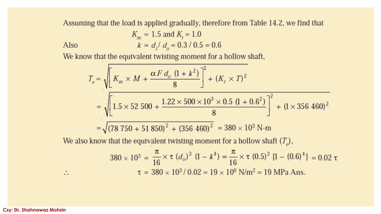
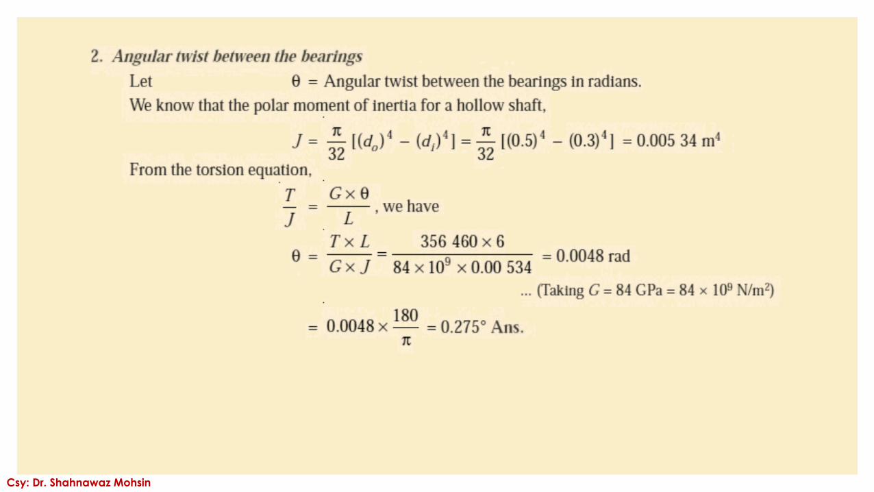
Example 13: A hollow shaft of 0.5 m outside diameter and 0.3 m inside diameter is used to drive a propeller of a marine vessel. The shaft is mounted on bearings 6 metre apart and it transmits 5600 kW at 150 r.p.m. The maximum axial propeller thrust is 500 kN and the shaft weighs 70 kN. Determine :1. The maximum shear stress developed in the shaft, and2. The angular twist between the bearings.
Csy: Dr. Shahnawaz Mohsin
Csy: Dr. Shahnawaz Mohsin
Csy: Dr. Shahnawaz Mohsin
Csy: Dr. Shahnawaz Mohsin
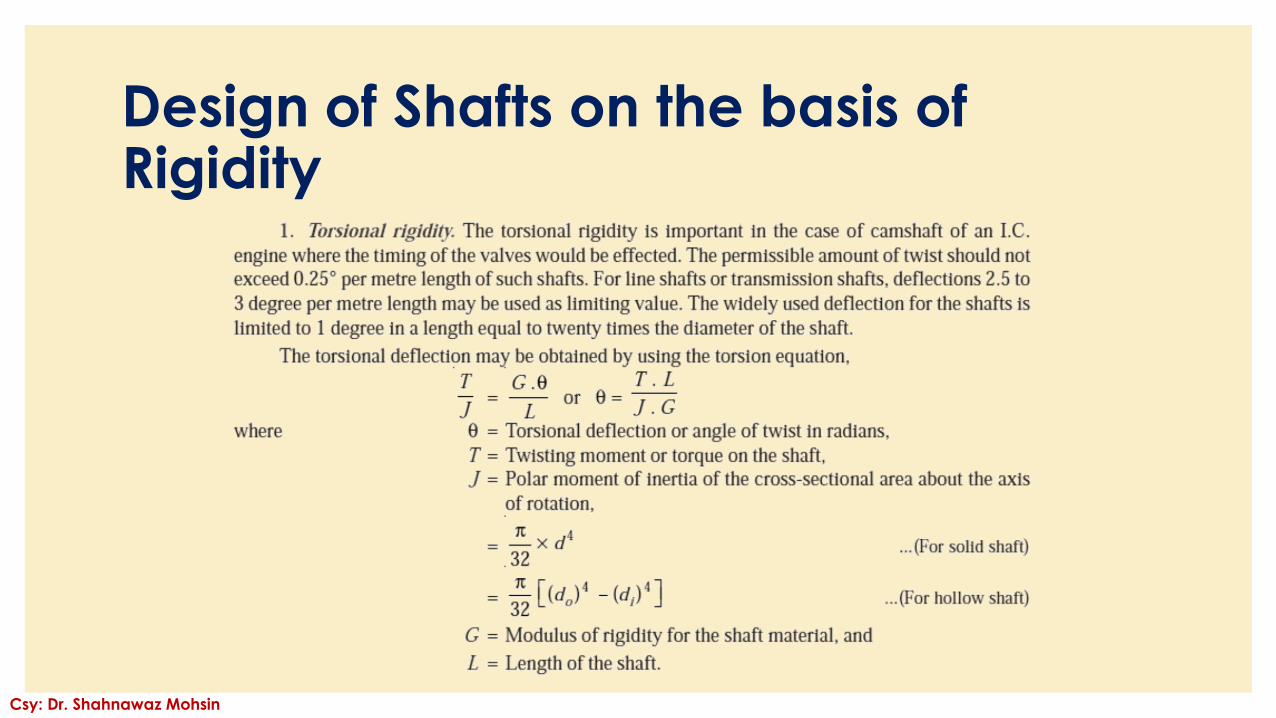
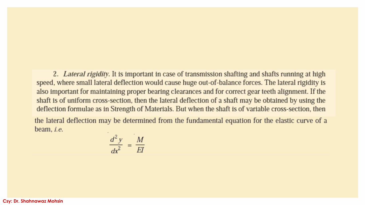
Design of Shafts on the basis of Rigidity
Csy: Dr. Shahnawaz Mohsin
Csy: Dr. Shahnawaz Mohsin
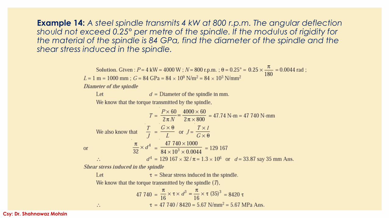
Example 14: A steel spindle transmits 4 kW at 800 r.p.m. The angular deflection should not exceed 0.25° per metre of the spindle. If the modulus of rigidity for the material of the spindle is 84 GPa, find the diameter of the spindle and the shear stress induced in the spindle.
Csy: Dr. Shahnawaz Mohsin
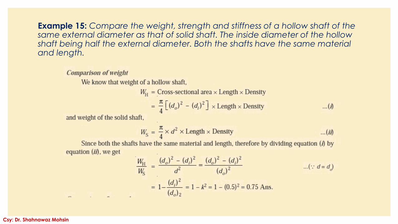
Example 15: Compare the weight, strength and stiffness of a hollow shaft of the same external diameter as that of solid shaft. The inside diameter of the hollow shaft being half the external diameter. Both the shafts have the same material and length.
Csy: Dr. Shahnawaz Mohsin
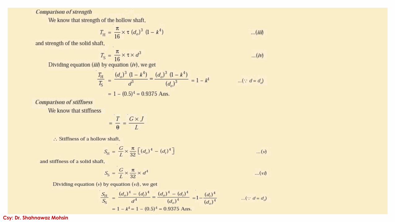
Csy: Dr. Shahnawaz Mohsin
Csy: Dr. Shahnawaz Mohsin
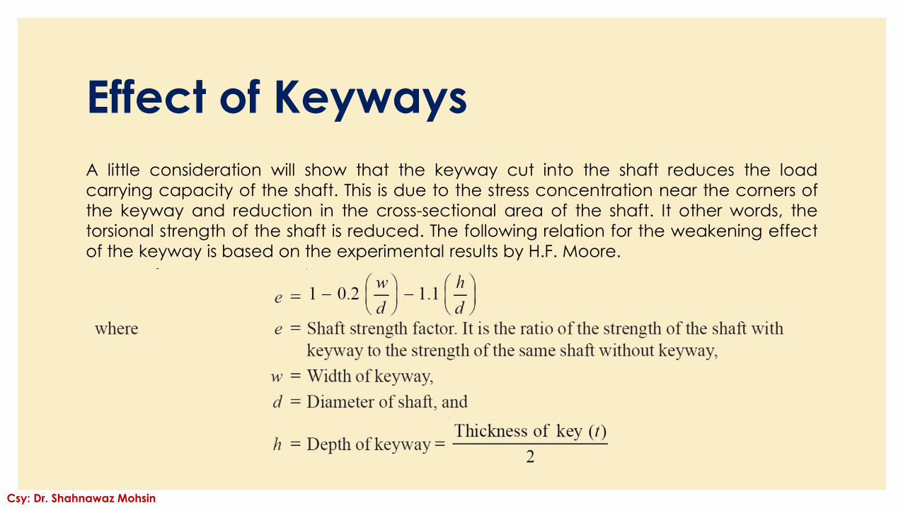
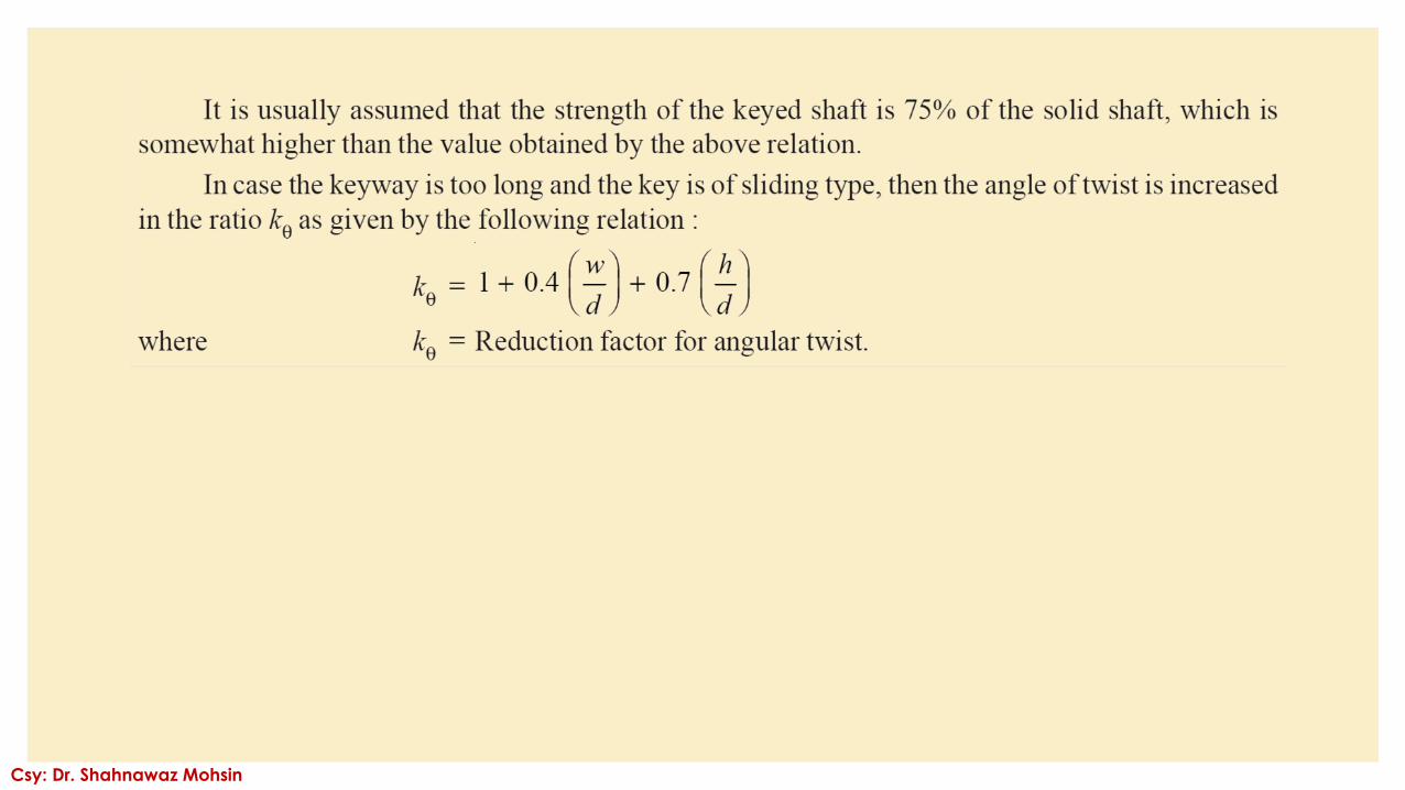
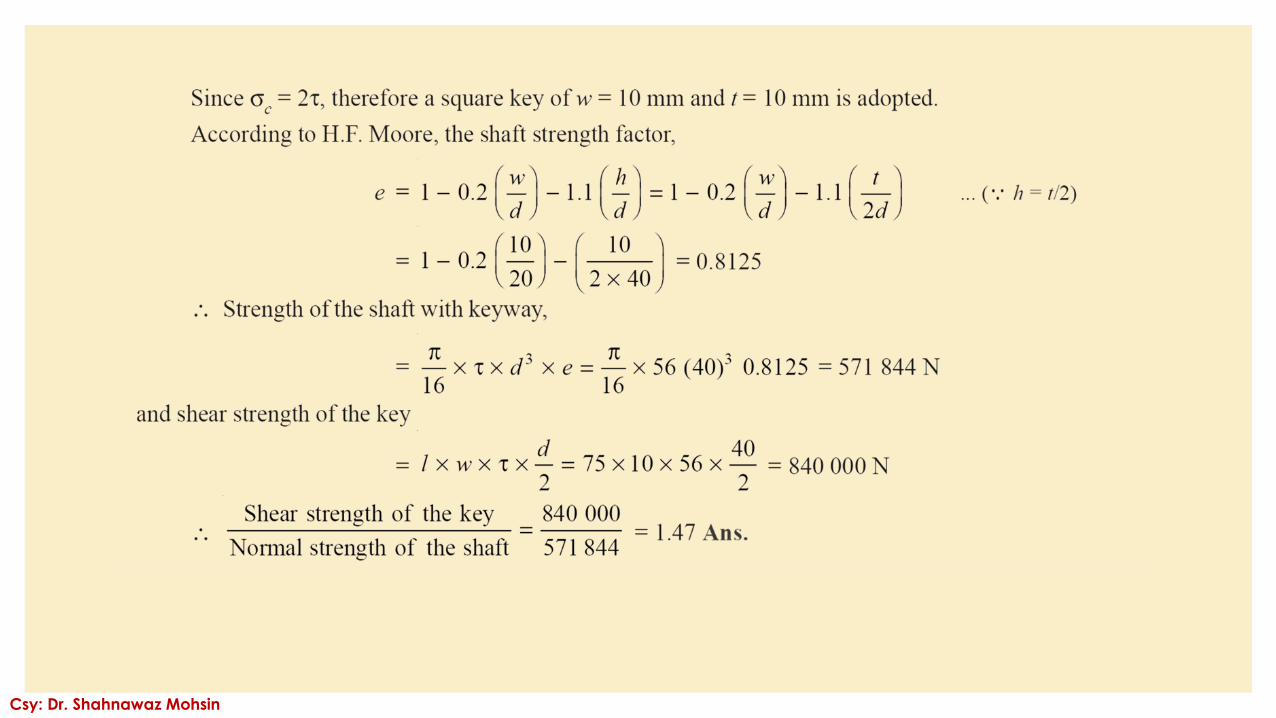
Effect of Keyways
A little consideration will show that the keyway cut into the shaft reduces the load
carrying capacity of the shaft. This is due to the stress concentration near the corners of
the keyway and reduction in the cross-sectional area of the shaft. It other words, the
torsional strength of the shaft is reduced. The following relation for the weakening effect
of the keyway is based on the experimental results by H.F. Moore.
Csy: Dr. Shahnawaz Mohsin
Csy: Dr. Shahnawaz Mohsin
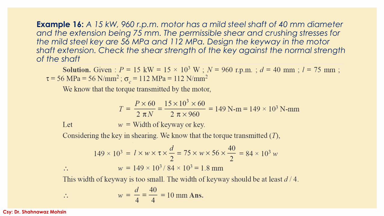
Example 16: A 15 kW, 960 r.p.m. motor has a mild steel shaft of 40 mm diameter and the extension being 75 mm. The permissible shear and crushing stresses for the mild steel key are 56 MPa and 112 MPa. Design the keyway in the motor shaft extension. Check the shear strength of the key against the normal strength of the shaft
Csy: Dr. Shahnawaz Mohsin
Csy: Dr. Shahnawaz Mohsin