electrical engineering
TRANSCRIPT
Electrical Engineering

V. Venkatesh
Electrical Engineering
Alpha Science International Ltd.Oxford, U.K.
α
V. VenkateshProfessor Department of Electronics & Communication EngineeringChannabasaveshwara Institute of TechnologyGubbi, Karnataka
Copyright © 2014
ALPHA SCIENCE INTERNATIONAL LTD.7200 The Quorum, Oxford Business Park NorthGarsington Road, Oxford OX4 2JZ, U.K.
www.alphasci.com
All rights reserved. No part of this publication may be reproduced, stored in a retrieval system, or transmitted in any form or by any means, electronic, mechanical, photocopying, recording or otherwise, without prior written permission of the publisher.
ISBN 978-1-84265-858-1
Printed in India
Electrical Engineering
324 pgs. | 234 figs. | 10 tbls.
Electrical Engineering is a semi-professional and professional engineering science that deals with the study and/or application of electricity, electromagnetism and the equipments for measurement, power generation and distribution and also safety mechanisms.
The goal of this book is to provide the reader with a comprehensive introduction to the fundamental aspects of Electrical Engineering, which helps any student to understand the concept.
The most important prerequisite to the material of this book is a solid background in teaching this subject since twenty five years. Familiarity with the subject helped to simplify the complicated issues.
In this book, the approach is made simple, clear and precise. Concepts are clearly explained, derivations are made clear and numerous examples are solved in such a way that the students can understand the proper approach and helps for self learning.
This book includes important points, many solved examples, multiple choice questions, review questions and exercises with answers.
Also, this book is useful to teach and to set the question paper for tests/quizzes/ university examination question paper.
I am thankful to Narosa Publishing House Pvt. Ltd., New Delhi for the encouragement in bringing out this book.
Also, I am thankful to Dr. Suresh Kumar D.S., Director, Channabasaveshwara Institute of Technology, Gubbi, Tumkur for his support.
I would like to thank my wife Smt. Kamala V., my son Naganand V. and daughter Deepthi V. for their cooperation.
V. Venkatesh
Preface

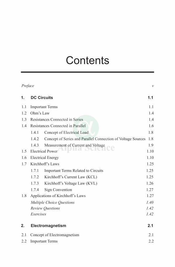
Preface v
1. DC Circuits 1.1
1.1 Important Terms 1.11.2 Ohm’s Law 1.41.3 Resistances Connected in Series 1.41.4 Resistances Connected in Parallel 1.6
1.4.1 Concept of Electrical Load 1.81.4.2 Concept of Series and Parallel Connection of Voltage Sources 1.81.4.3 Measurement of Current and Voltage 1.9
1.5 Electrical Power 1.101.6 Electrical Energy 1.101.7 Kirchhoff’s Laws 1.25
1.7.1 Important Terms Related to Circuits 1.251.7.2 Kirchhoff’s Current Law (KCL) 1.251.7.3 Kirchhoff’s Voltage Law (KVL) 1.261.7.4 Sign Convention 1.27
1.8 Applications of Kirchhoff’s Laws 1.27Multiple Choice Questions 1.40Review Questions 1.42 Exercises 1.42
2. Electromagnetism 2.1
2.1 Concept of Electromagnetism 2.12.2 Important Terms 2.2
Contents
viii Contentsviii Contents
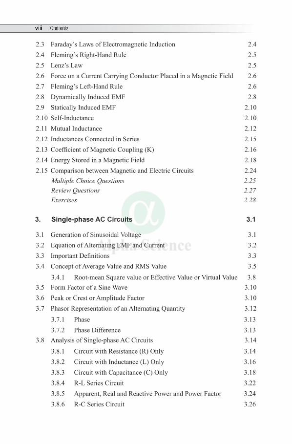
2.3 Faraday’s Laws of Electromagnetic Induction 2.42.4 Fleming’s Right-Hand Rule 2.52.5 Lenz’s Law 2.52.6 Force on a Current Carrying Conductor Placed in a Magnetic Field 2.62.7 Fleming’s Left-Hand Rule 2.62.8 Dynamically Induced EMF 2.82.9 Statically Induced EMF 2.102.10 Self-Inductance 2.102.11 Mutual Inductance 2.122.12 Inductances Connected in Series 2.152.13 Coefficient of Magnetic Coupling (K) 2.162.14 Energy Stored in a Magnetic Field 2.182.15 Comparison between Magnetic and Electric Circuits 2.24
Multiple Choice Questions 2.25Review Questions 2.27 Exercises 2.28
3. Single-phase AC Circuits 3.1
3.1 Generation of Sinusoidal Voltage 3.13.2 Equation of Alternating EMF and Current 3.23.3 Important Definitions 3.33.4 Concept of Average Value and RMS Value 3.5
3.4.1 Root-mean Square value or Effective Value or Virtual Value 3.83.5 Form Factor of a Sine Wave 3.103.6 Peak or Crest or Amplitude Factor 3.103.7 Phasor Representation of an Alternating Quantity 3.12
3.7.1 Phase 3.133.7.2 Phase Difference 3.13
3.8 Analysis of Single-phase AC Circuits 3.143.8.1 Circuit with Resistance (R) Only 3.143.8.2 Circuit with Inductance (L) Only 3.163.8.3 Circuit with Capacitance (C) Only 3.183.8.4 R-L Series Circuit 3.223.8.5 Apparent, Real and Reactive Power and Power Factor 3.243.8.6 R-C Series Circuit 3.26
Contents ixContents ix
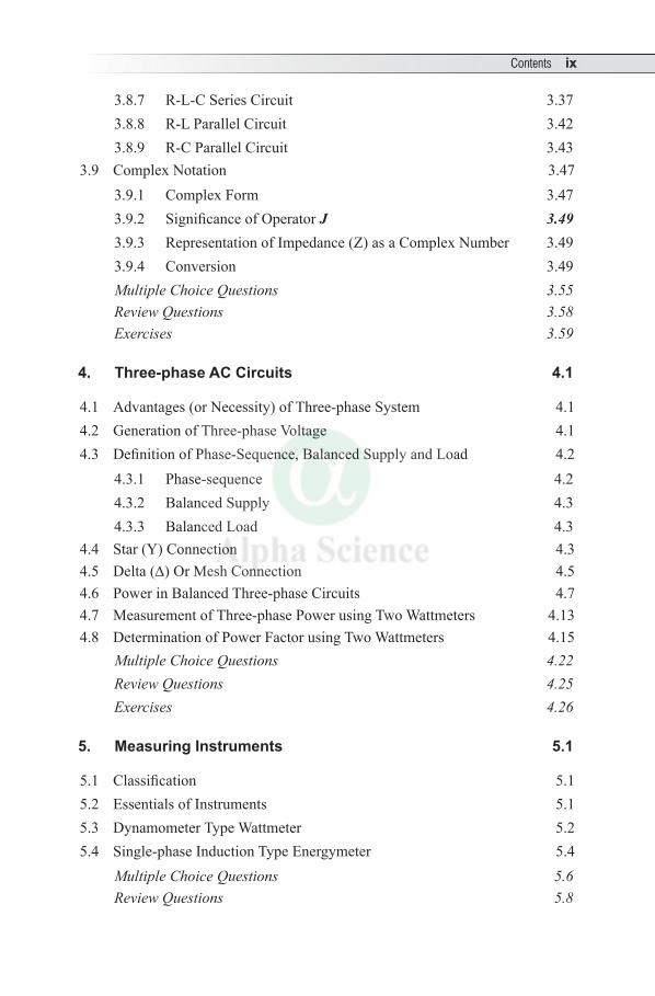
3.8.7 R-L-C Series Circuit 3.373.8.8 R-L Parallel Circuit 3.423.8.9 R-C Parallel Circuit 3.43
3.9 Complex Notation 3.473.9.1 Complex Form 3.473.9.2 Significance of Operator J 3.493.9.3 Representation of Impedance (Z) as a Complex Number 3.493.9.4 Conversion 3.49Multiple Choice Questions 3.55Review Questions 3.58 Exercises 3.59
4. Three-phase AC Circuits 4.1
4.1 Advantages (or Necessity) of Three-phase System 4.14.2 Generation of Three-phase Voltage 4.14.3 Definition of Phase-Sequence, Balanced Supply and Load 4.2
4.3.1 Phase-sequence 4.24.3.2 Balanced Supply 4.34.3.3 Balanced Load 4.3
4.4 Star (Y) Connection 4.34.5 Delta (D) Or Mesh Connection 4.54.6 Power in Balanced Three-phase Circuits 4.74.7 Measurement of Three-phase Power using Two Wattmeters 4.134.8 Determination of Power Factor using Two Wattmeters 4.15
Multiple Choice Questions 4.22Review Questions 4.25 Exercises 4.26
5. Measuring Instruments 5.1
5.1 Classification 5.15.2 Essentials of Instruments 5.15.3 Dynamometer Type Wattmeter 5.25.4 Single-phase Induction Type Energymeter 5.4
Multiple Choice Questions 5.6Review Questions 5.8
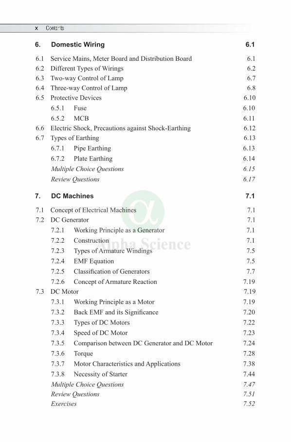
6. Domestic Wiring 6.1
6.1 Service Mains, Meter Board and Distribution Board 6.16.2 Different Types of Wirings 6.26.3 Two-way Control of Lamp 6.76.4 Three-way Control of Lamp 6.86.5 Protective Devices 6.10
6.5.1 Fuse 6.106.5.2 MCB 6.11
6.6 Electric Shock, Precautions against Shock-Earthing 6.126.7 Types of Earthing 6.13
6.7.1 Pipe Earthing 6.136.7.2 Plate Earthing 6.14Multiple Choice Questions 6.15Review Questions 6.17
7. DC Machines 7.1
7.1 Concept of Electrical Machines 7.17.2 DC Generator 7.1
7.2.1 Working Principle as a Generator 7.17.2.2 Construction 7.17.2.3 Types of Armature Windings 7.57.2.4 EMF Equation 7.57.2.5 Classification of Generators 7.77.2.6 Concept of Armature Reaction 7.19
7.3 DC Motor 7.197.3.1 Working Principle as a Motor 7.197.3.2 Back EMF and its Significance 7.207.3.3 Types of DC Motors 7.227.3.4 Speed of DC Motor 7.237.3.5 Comparison between DC Generator and DC Motor 7.247.3.6 Torque 7.287.3.7 Motor Characteristics and Applications 7.387.3.8 Necessity of Starter 7.44Multiple Choice Questions 7.47Review Questions 7.51 Exercises 7.52
x Contents
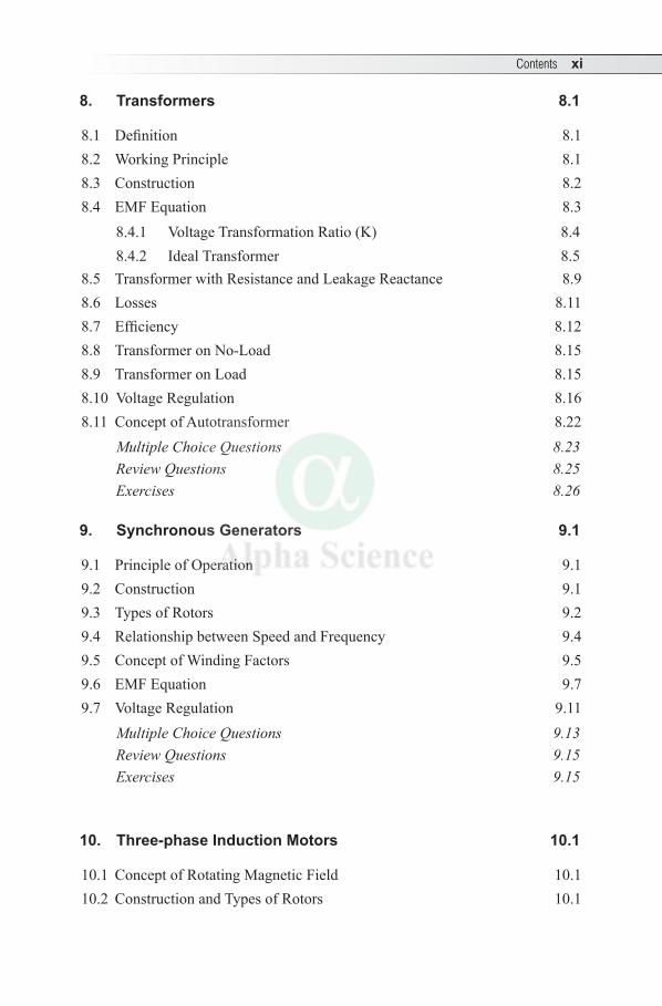
8. Transformers 8.1
8.1 Definition 8.18.2 Working Principle 8.18.3 Construction 8.28.4 EMF Equation 8.3
8.4.1 Voltage Transformation Ratio (K) 8.48.4.2 Ideal Transformer 8.5
8.5 Transformer with Resistance and Leakage Reactance 8.98.6 Losses 8.118.7 Efficiency 8.128.8 Transformer on No-Load 8.158.9 Transformer on Load 8.158.10 Voltage Regulation 8.168.11 Concept of Autotransformer 8.22
Multiple Choice Questions 8.23Review Questions 8.25 Exercises 8.26
9. Synchronous Generators 9.1
9.1 Principle of Operation 9.19.2 Construction 9.19.3 Types of Rotors 9.29.4 Relationship between Speed and Frequency 9.49.5 Concept of Winding Factors 9.59.6 EMF Equation 9.79.7 Voltage Regulation 9.11
Multiple Choice Questions 9.13Review Questions 9.15 Exercises 9.15
10. Three-phase Induction Motors 10.1
10.1 Concept of Rotating Magnetic Field 10.110.2 Construction and Types of Rotors 10.1
Contents xi
xii Contents
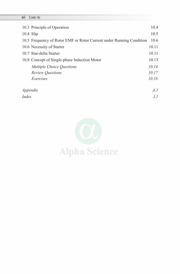
10.3 Principle of Operation 10.410.4 Slip 10.510.5 Frequency of Rotor EMF or Rotor Current under Running Condition 10.610.6 Necessity of Starter 10.1110.7 Star-delta Starter 10.1110.8 Concept of Single-phase Induction Motor 10.13
Multiple Choice Questions 10.14Review Questions 10.17 Exercises 10.18
Appendix A.1Index I.1
1.1 IMPORTANT TERMS
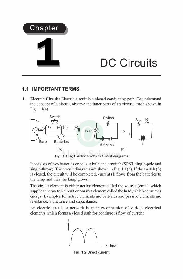
1. Electric Circuit: Electric circuit is a closed conducting path. To understand the concept of a circuit, observe the inner parts of an electric torch shown in Fig. 1.1(a).
BatteriesBulb
Switch
__ ++
Batteries
Bulb
Switch
_+
SR
E
II
(+) (–)(+) (–)
(a) (b)
Fig. 1.1 (a) Electric torch (b) Circuit diagrams
It consists of two batteries or cells, a bulb and a switch (SPST, single-pole and single-throw). The circuit diagrams are shown in Fig. 1.1(b). If the switch (S) is closed, the circuit will be completed, current (I) flows from the batteries to the lamp and thus the lamp glows.
The circuit element is either active element called the source (emf ), which supplies energy to a circuit or passive element called the load, which consumes energy. Examples for active elements are batteries and passive elements are resistance, inductance and capacitance.
An electric circuit or network is an interconnection of various electrical elements which forms a closed path for continuous flow of current.
time
I
0
Fig. 1.2 Direct current
DC Circuits1Chapter
1.2 Electrical Engineering
A battery provides a steady voltage, so that current flows in one direction and thus called direct current (dc). A circuit, which deals with dc is called dc circuit.
2. Current: According to atomic theory, an atom consists of protons (positively charged) in the central nucleus and equal number of revolving electrons (negatively charged) in various orbits. By the application of an external force, electrons of the outermost orbits get removed from the parent atom. The continuous drift or movement of electrons in a particular direction due to an external force causes the flow of current.
‘The continuous flow of electrons in any conductor in a particular direction constitutes electric current (I)’.
Also, removal of electrons makes the atom positively charged and addition of an electron makes the atom negatively charged. The unit of charge Q is coulomb (C).
‘The rate of flow of electric charges through a cross-sectional area of a conductor is called the current’.
i.e., I = Qd
dt The unit of current is ampere (A). Ampere is that current, which if maintained
in two straight parallel conductors of infinite length, of negligible circular cross-section and placed 1 metre apart in vacuum produces between these conductors a force of 2 × 10⁻⁷ newton per metre length.
Also, 1 ampere is that amount of current which flows through a circuit, when 1 coulomb of charge per second is transferred through a point in a circuit.
Important Points
l Current flows from higher potential to lower potential or from positive to negative (flow of current is analogous to flow of water through a pipe line).
l The term current or electric current represents the conventional current, which flows in opposite direction to that of electron current.
3. Electromotive Force or Voltage: Electromotive force or EMF (E) is that which tends to produce an electric current in a circuit. EMF is not a force, but it represents the energy. It is a driving influence that causes the current to flow.
The term voltage (V) means potential difference (pd) between two points in an electrical circuit required to drive the current between them.
The unit of emf and voltage is volt (V), which is defined as the potential difference across a unit resistance causing a unit current.
DC Circuits 1.3
4. Resistance: Resistance (R) is defined as that property of a substance, which opposes the flow of electrons or electric current through it. Its unit is ohm (W), which is defined as the resistance between two points of a conductor when a potential difference of 1 volt, applied produces a current of 1 ampere.
Also, ohm is the resistance of a circuit in which a current of 1 ampere generates heat at the rate of 1 watt.
The value of resistance depends upon the following factors: (i) The resistance of a conductor varies directly as its length (l).(ii) The resistance of a conductor varies inversely as its cross sectional area (A).
Therefore, R = rlA
where r is a constant of proportionality called specific resistance or resistivity of the material and its unit is ohm-metre (W - m). For popper, P = 1.72 × 10⁻⁸.Effect of Temperature on Resistance(i) As temperature increases the resistance also increases for pure metals and said
to have positive temperature co-efficient. Examples are Silver, Copper and Aluminum. They are called the good conductors as they have low resistance.
(ii) As temperature increases the resistance decreases for insulators and said to have negative temperature co-efficient. Examples are Mica, Porcelain, Carbon, etc. They are called the insulators as they have high resistance.
Important Points
l As current flows through a resistance, it causes a voltage drop across it and its unit is volt (V).
l The reciprocal (or inverse) of resistance is called the conductance (G). The SI unit of conductance is siemen (S).
l Resistance is connected in series to limit the current. The resistance connected across the supply is called the load or the load resistance. Example: Filament lamp.
l The resistance (or resistor) may be either a fixed resistance or variable resistance (called the rheostat).
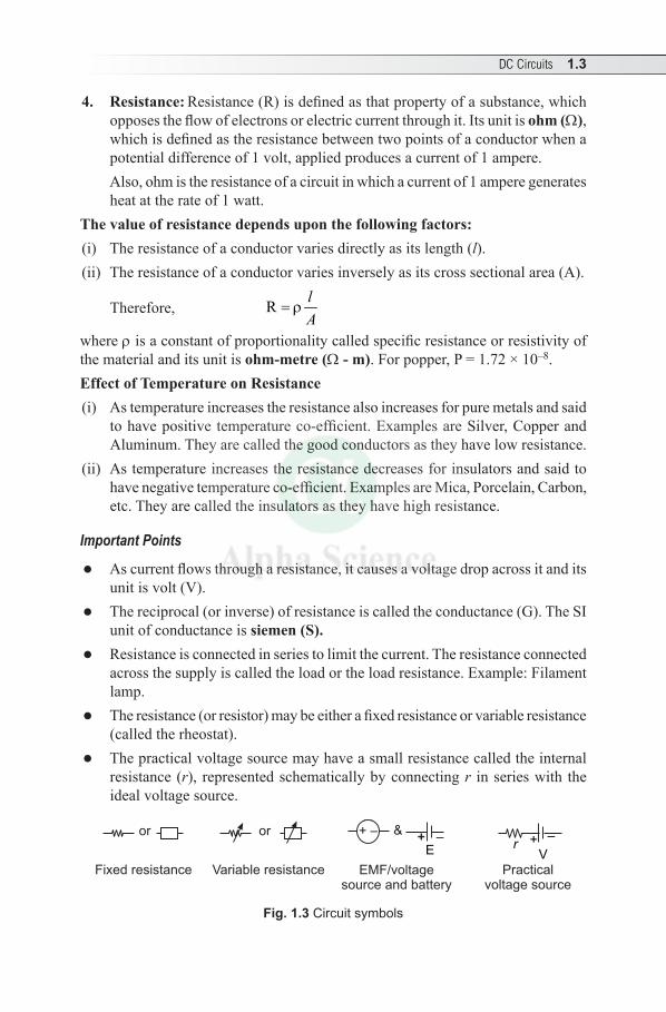
l The practical voltage source may have a small resistance called the internal resistance (r), represented schematically by connecting r in series with the ideal voltage source.
Fixed resistance
or or +- &+ –+
E+ – + –
Vr
Variable resistance EMF/voltagesource and battery
Practicalvoltage source
Fig. 1.3 Circuit symbols
1.4 Electrical Engineering
1.2 OHM’S LAW
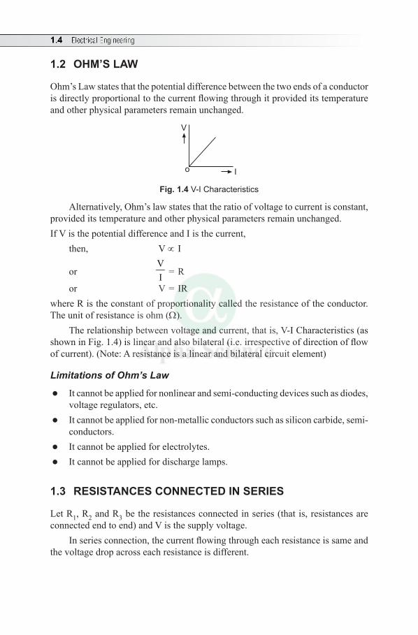
Ohm’s Law states that the potential difference between the two ends of a conductor is directly proportional to the current flowing through it provided its temperature and other physical parameters remain unchanged.
V
Io
Fig. 1.4 V-I Characteristics
Alternatively, Ohm’s law states that the ratio of voltage to current is constant, provided its temperature and other physical parameters remain unchanged.If V is the potential difference and I is the current,
then, V ∝ I
or VI = R
or V = IRwhere R is the constant of proportionality called the resistance of the conductor. The unit of resistance is ohm (W).
The relationship between voltage and current, that is, V-I Characteristics (as shown in Fig. 1.4) is linear and also bilateral (i.e. irrespective of direction of flow of current). (Note: A resistance is a linear and bilateral circuit element)
Limitations of Ohm’s Law
l It cannot be applied for nonlinear and semi-conducting devices such as diodes, voltage regulators, etc.
l It cannot be applied for non-metallic conductors such as silicon carbide, semi-conductors.
l It cannot be applied for electrolytes. l It cannot be applied for discharge lamps.
1.3 RESISTANCES CONNECTED IN SERIES
Let R1, R2 and R3 be the resistances connected in series (that is, resistances are connected end to end) and V is the supply voltage.
In series connection, the current flowing through each resistance is same and the voltage drop across each resistance is different.
DC Circuits 1.5
I
V 1
R1 R2 R3
V 2 V3
V+ –
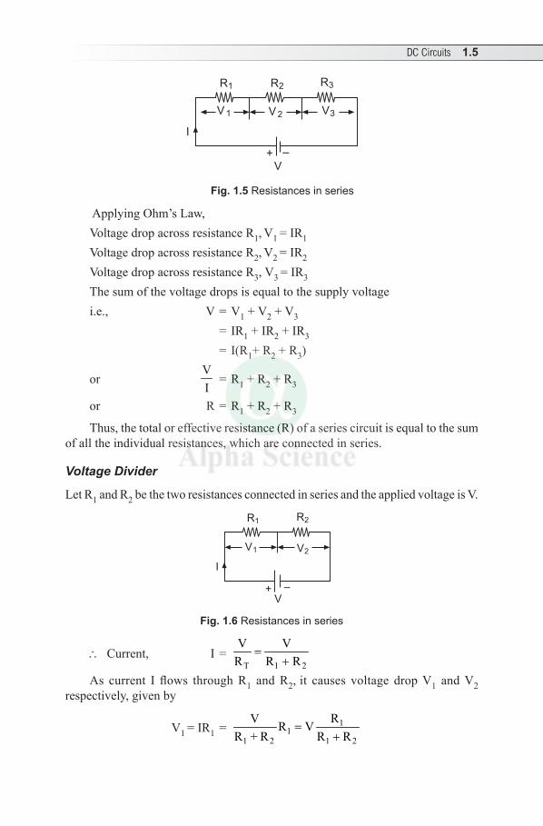
Fig. 1.5 Resistances in series
Applying Ohm’s Law, Voltage drop across resistance R1, V1 = IR1 Voltage drop across resistance R2, V2 = IR2 Voltage drop across resistance R3, V3 = IR3 The sum of the voltage drops is equal to the supply voltage i.e., V = V1 + V2 + V 3 = IR1 + IR2 + IR3
= I(R1+ R2 + R3)
or VI
= R1 + R2 + R3
or R = R1 + R2 + R3
Thus, the total or effective resistance (R) of a series circuit is equal to the sum of all the individual resistances, which are connected in series.
Voltage Divider
Let R1 and R2 be the two resistances connected in series and the applied voltage is V.
R1 R2
V1 V
V
I
2
+ –
Fig. 1.6 Resistances in series
∴ Current, I = T 1 2
V VR R R
=+
As current I flows through R1 and R2, it causes voltage drop V1 and V2 respectively, given by
V1 = IR1 = 11
1 2 1 2
RV R VR + R R R
=+
1.6 Electrical Engineering
Similarly, V2 = IR2 = V 2
1 2
RR R+
Thus, with resistances in series the applied voltage divides among the resistances in the direct ratio of their resistances.
1.4 RESISTANCES CONNECTED IN PARALLEL
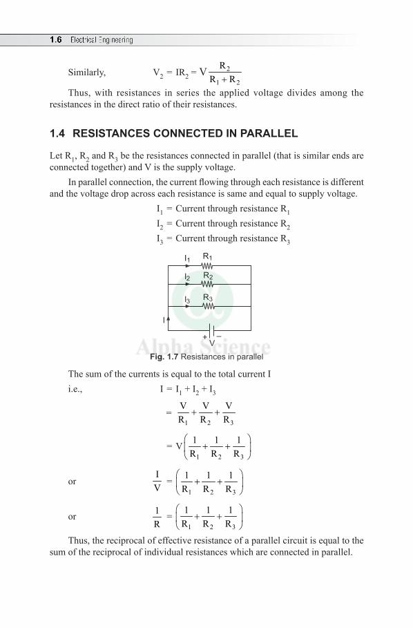
Let R1, R2 and R3 be the resistances connected in parallel (that is similar ends are connected together) and V is the supply voltage.
In parallel connection, the current flowing through each resistance is different and the voltage drop across each resistance is same and equal to supply voltage.
I1 = Current through resistance R1 I2 = Current through resistance R2 I3 = Current through resistance R3
V
I
I1 R1
R2
R3
I2
I3
+ –
Fig. 1.7 Resistances in parallel
The sum of the currents is equal to the total current I
i.e., I = I1 + I2 + I 3
= 1 2 3
V V VR R R
+ +
= V1 2 3
1 1 1R R R
+ +
or IV
= 1 2 3
1 1 1R R R
+ +
or 1R
= 1 2 3
1 1 1R R R
+ +
Thus, the reciprocal of effective resistance of a parallel circuit is equal to the
sum of the reciprocal of individual resistances which are connected in parallel.
DC Circuits 1.7
Important Point
For n number of identical resistances, each of resistance R, which are connected in parallel, the equivalent resistance of the parallel combination is R/n.
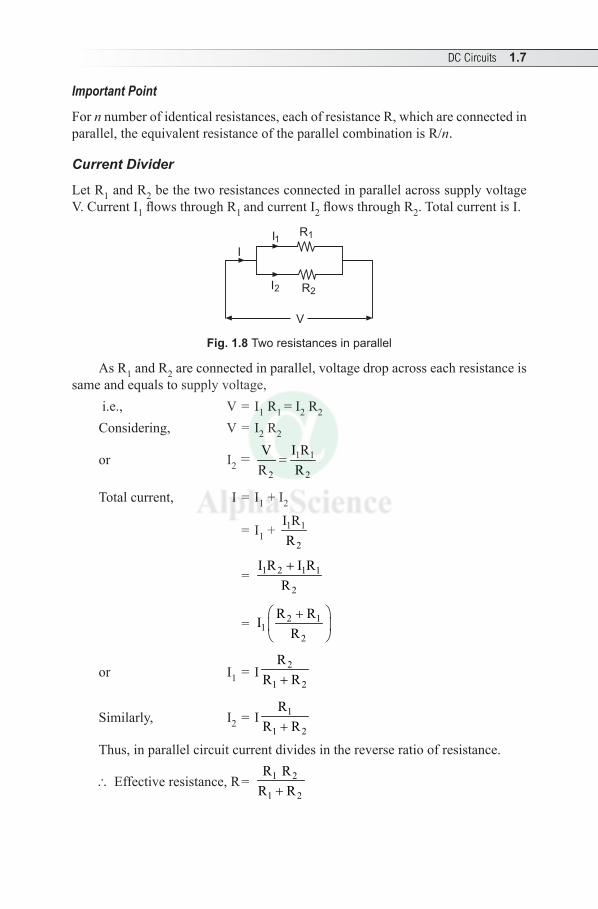
Current Divider
Let R1 and R2 be the two resistances connected in parallel across supply voltage V. Current I1 flows through R1 and current I2 flows through R2. Total current is I.
I
I1R1
R2I2
V
Fig. 1.8 Two resistances in parallel
As R1 and R2 are connected in parallel, voltage drop across each resistance is same and equals to supply voltage,
i.e., V = I1 R1 = I2 R2
Considering, V = I2 R2
or I2 = 1 1
2 2
I RVR R
=
Total current, I = I1 + I2
= I1 + 1 1
2
I RR
= 1 2 1 1
2
I R I RR+
= 2 11
2
R RIR
+
or I1 = I 2
1 2
RR R+
Similarly, I2 = I 1
1 2
RR R+
Thus, in parallel circuit current divides in the reverse ratio of resistance.
∴ Effective resistance, R = 1 2
1 2
R RR R+
1.8 Electrical Engineering
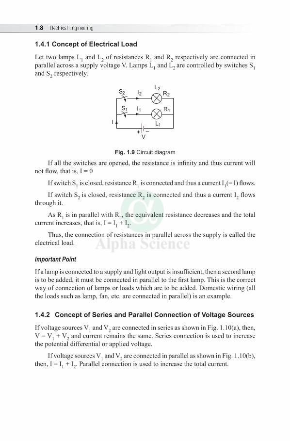
1.4.1 Concept of Electrical Load
Let two lamps L1 and L2 of resistances R1 and R2 respectively are connected in parallel across a supply voltage V. Lamps L1 and L2 are controlled by switches S1 and S2 respectively.
V
I
+ –
S1
S2 I2
I1
R2
R1
L2
L1
Fig. 1.9 Circuit diagram
If all the switches are opened, the resistance is infinity and thus current will not flow, that is, I = 0
If switch S1 is closed, resistance R1 is connected and thus a current I1(= I) flows.
If switch S2 is closed, resistance R2 is connected and thus a current I2 flows through it.
As R1 is in parallel with R2, the equivalent resistance decreases and the total current increases, that is, I = I1 + I2.
Thus, the connection of resistances in parallel across the supply is called the electrical load.
Important Point
If a lamp is connected to a supply and light output is insufficient, then a second lamp is to be added, it must be connected in parallel to the first lamp. This is the correct way of connection of lamps or loads which are to be added. Domestic wiring (all the loads such as lamp, fan, etc. are connected in parallel) is an example.
1.4.2 Concept of Series and Parallel Connection of Voltage Sources
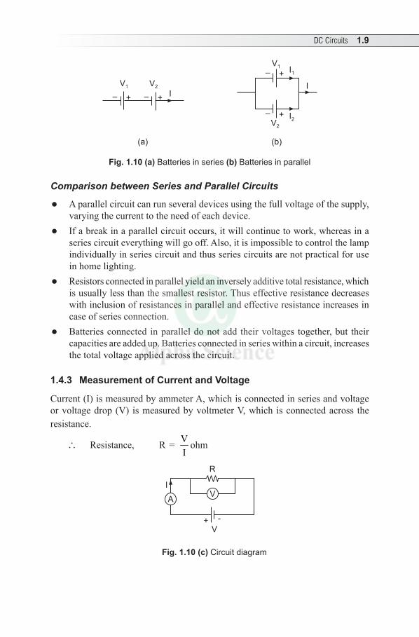
If voltage sources V1 and V2 are connected in series as shown in Fig. 1.10(a), then, V = V1 + V2 and current remains the same. Series connection is used to increase the potential differential or applied voltage.
If voltage sources V1 and V2 are connected in parallel as shown in Fig. 1.10(b), then, I = I1 + I2. Parallel connection is used to increase the total current.
DC Circuits 1.9
V1 V2
V1
V2
I
– +
– +
–– ++
I1
I2
I
(a) (b)
Fig. 1.10 (a) Batteries in series (b) Batteries in parallel
Comparison between Series and Parallel Circuits
l A parallel circuit can run several devices using the full voltage of the supply, varying the current to the need of each device.
l If a break in a parallel circuit occurs, it will continue to work, whereas in a series circuit everything will go off. Also, it is impossible to control the lamp individually in series circuit and thus series circuits are not practical for use in home lighting.
l Resistors connected in parallel yield an inversely additive total resistance, which is usually less than the smallest resistor. Thus effective resistance decreases with inclusion of resistances in parallel and effective resistance increases in case of series connection.
l Batteries connected in parallel do not add their voltages together, but their capacities are added up. Batteries connected in series within a circuit, increases the total voltage applied across the circuit.
1.4.3 Measurement of Current and Voltage
Current (I) is measured by ammeter A, which is connected in series and voltage or voltage drop (V) is measured by voltmeter V, which is connected across the resistance.
∴ Resistance, R = VI
ohm
V
I
R
+ -
AV
Fig. 1.10 (c) Circuit diagram
1.10 Electrical Engineering
1.5 ELECTRICAL POWER
Power is the work done per second. Its unit is joule/second or newton-metre/second (N-m/s).
i.e., Power, P = worktime
The power consumed in an electrical circuit is 1 watt if potential difference applied across the circuit is 1 volt which causes 1 ampere of current to flow through the circuit.
i.e., P = VI According to Ohm’s Law, V = IR∴ P = I2 R
or P = 2V
R
The practical unit of electrical power is watt (W) or kilo watt (kW). Important point: Both for a series and a parallel circuit, powers are additive.
1.6 ELECTRICAL ENERGY
Electrical energy is the total amount of work done. Its unit is joule (J). Electrical energy is the consumption of electrical power of 1 watt for 1 second. Thus,
Electrical Energy = Power × time = VI t = I2 R × t watt-second or joule. Practical unit of electrical energy is kilo watt-hour (kWh) also, called BOARD
OF TRADE UNIT (BOTU) or ‘unit’.
1 kWh = 1kW × 1hour = 1000W × (60 minutes × 60 seconds) = 3.6 × 10⁶ watt sec or J.
Solved Examples
Example 1.1 Find the resistance of an electrical appliance, which takes 5A when connected to a 110V supply. Also, find the power consumed by the resistor.
Solution: Given: I = 5A and V = 110 volt
Resistance, R = V 110 22 AI 5= =
Power consumed, P = VI = 110 × 5 = 550W = 0.55 kW
Example 1.2 If an electric heater is connected to a 240V supply, it draws a current of 8A for 12 hours. What is the energy consumed in kWh?
DC Circuits 1.11
Solution: Given: I = 8A, V = 240 volt, t = 12 hours Power, P = VI = 240 × 8 = 1920W = 1.92 kW∴ Energy, Pt = 1.92 × 12 = 23 kWh
Example 1.3 What is the power output of a 240V lamp carrying a rated current of 0.25A? Suppose a similar lamp is connected in parallel with this lamp, what is the supply current required to give the same power output in each lamp?
Solution: Given: V = 240 volt, Current with single lamp, I = 0.25 A Power output of lamp, P = V I = 240 × 0.25 = 60WIf a second lamp of 60W is connected in parallel to the first one, Total power output, PT = 60W + 60W = 120W
∴ Supply current, I = TP 120V 240
= = 0.5 A
Example 1.4 An electric device having a resistance of 8 ohm takes a current of 5A. Find the rate of heat dissipated and the heat dissipated in 30 seconds.
Solution: Given: I = 5A and R = 8WRate of heat dissipation, P = I2 R = 52 × 8 = 200WHeat dissipated in 30 sec., P × t = 200 × 30 = 6000J
Example 1.5 A 100 W lamp is used for six hours a day. Find (i) Energy consumed per month and (ii) Cost of energy if each unit costs ` 5.
Solution: Given: P = 100W, consumption: 6 hours, No. of days–30 in that month, cost/unit = ` 1.20
Energy consumption/day = P 100No.of hours/day 6
1000 1000× = × = 0.6 kWh
∴ Energy consumption/month, 0.6 × 30 = 18 kWh Cost of energy/month, ` 5 × 18 kWh = ` 90/-
Example 1.6 A circuit takes a current of 5A at 100V supply. What value of resistance is to be connected in series to limit the current to 10A?
Solution: Given: Initial current I1 = 5 A, V = 100 volt, Final current I2 = 2 A
With initial current I1, resistance R1 = 1
V 100I 5= = 20W
1.12 Electrical Engineering
With final current I2, resistance R2 = 2
V 100I 2= = 50W
\ Value of resistance to be connected in series, R = R2 – R1 = 50 – 20 = 30W
Example 1.7 A device consists of 10 batteries each with an emf of 2V and an internal resistance of 0.02W. Calculate the rate at which heat is developed in an external circuit of resistance 0.25W when the batteries are connected (i) all in series and (ii) all in parallel.
Solution: Given: Number of batteries: 10, EMF of each battery = 2V, r = 0.02W, RL = 0.25W
(i) When all are connected in series: Equivalent emf, V = 2 ×10 = 20 V
Internal resistance, r = 0.02 × 10 = 0.2WTotal resistance Rt = r + RL = 0.2W + 0.25W = 0.45W
The circuit current, I = t
V 20R 0.45
= = 44.4A
\ Rate of heat developed, I2RL = 44.42 × 0.25 = 493A(ii) When all are connected in parallel: Equivalent emf, V = 2
Internal resistance, r = 0.0210
= 0.002W
Total resistance, Rt = r + RL = 0.002 + 0.25 = 0.252W
The circuit current, I = t
V 20R 0.252
= = 7.94 A
\ Rate of heat developed, I2RL = 7.942 × 0.25 = 15.76A
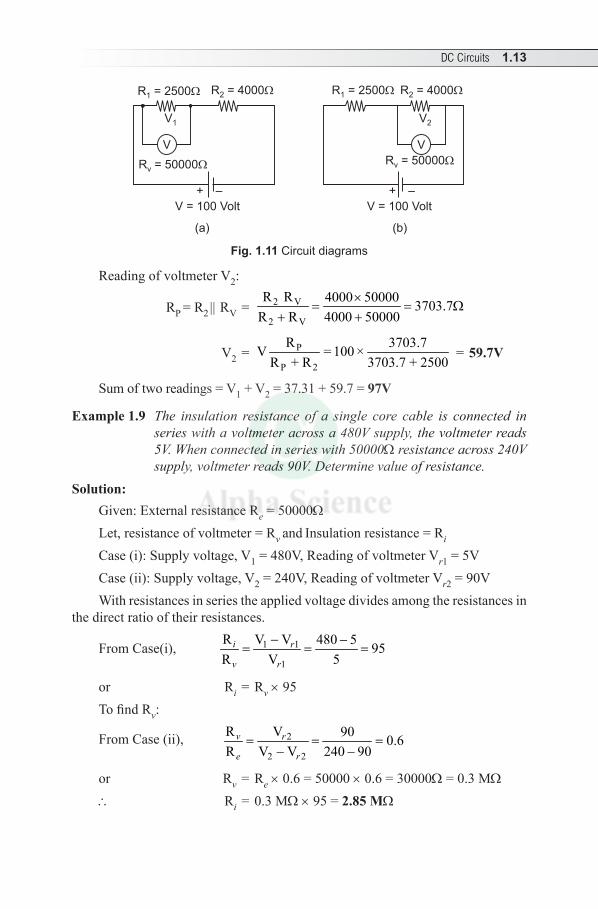
Example 1.8 Two resistances, R1 = 2500W and R2 = 4000W are connected in series and a voltage of 100V is applied. The voltage drop across R1 and R2 are measured successively by a voltmeter having a resistance of 50,000W. Find the sum of two readings.
Solution: Given: R1 = 2500W, R2 = 4000W, V = 100 volt and resistance voltmeter Rv = 50,000W Circuit diagram is drawn.
Reading of voltmeter V1:
RP = R1 || RV = 1 V
1 V
R R 2500 50000 2380.95R + R 2500 50000
×= = W
+
V1 = P
P 2
R 2380.95V 100R R 2380.95 4000
= ×+ +
= 37.31V
DC Circuits 1.13
V V
V = 100 VoltV = 100 Volt
R = 50000v
R = 25001 R = 40002
V1
R = 25001
V2
R = 50000v
R = 40002
+ – + –
(a) (b)
Fig. 1.11 Circuit diagrams
Reading of voltmeter V2:
RP = R2 || RV = 2 V
2 V
R R 4000 50000 3703.7R R 4000 50000
×= = W
+ +
V2 = P
P 2
R 3703.7V = 100 ×R + R 3703.7 + 2500
= 59.7V
Sum of two readings = V1 + V2 = 37.31 + 59.7 = 97V
Example 1.9 The insulation resistance of a single core cable is connected in series with a voltmeter across a 480V supply, the voltmeter reads 5V. When connected in series with 50000W resistance across 240V supply, voltmeter reads 90V. Determine value of resistance.
Solution: Given: External resistance Re = 50000W Let, resistance of voltmeter = Rv and Insulation resistance = Ri Case (i): Supply voltage, V1 = 480V, Reading of voltmeter Vr1 = 5VCase (ii): Supply voltage, V2 = 240V, Reading of voltmeter Vr2 = 90VWith resistances in series the applied voltage divides among the resistances in
the direct ratio of their resistances.
From Case(i), 1 1
1
R V V 480 5 95R V 5
− −= = =i r
v r
or Ri = Rv × 95To find Rv:
From Case (ii), 2
2 2
R V 90 0.6R V V 240 90
= = =− −
v r
e r
or Rv = Re × 0.6 = 50000 × 0.6 = 30000W = 0.3 MW
∴ Ri = 0.3 MW × 95 = 2.85 MW
1.14 Electrical Engineering
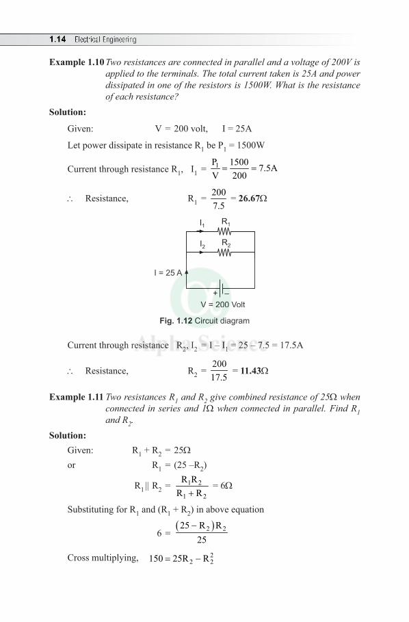
Example 1.10 Two resistances are connected in parallel and a voltage of 200V is applied to the terminals. The total current taken is 25A and power dissipated in one of the resistors is 1500W. What is the resistance of each resistance?
Solution:
Given: V = 200 volt, I = 25A
Let power dissipate in resistance R1 be P1 = 1500W
Current through resistance R1, I1 = 1P 1500 7.5AV 200= =
∴ Resistance, R1 = 2007.5
= 26.67W
V = 200 Volt
+ –
I = 25 A
I1 R1
I2 R2
Fig. 1.12 Circuit diagram
Current through resistance R2, I2 = I – I1 = 25 – 7.5 = 17.5A
∴ Resistance, R2 = 20017.5
= 11.43W
Example 1.11 Two resistances R1 and R2 give combined resistance of 25W when connected in series and 1W when connected in parallel. Find R1 and R2.
Solution: Given: R1 + R2 = 25W or R1 = (25 –R2)
R1 || R2 = 1 2
1 2
R RR R+
= 6W
Substituting for R1 and (R1 + R2) in above equation
6 = ( )2 225 R R
25−
Cross multiplying, 22 2150 25R R= −
DC Circuits 1.15
or 22 2150 25R R 0− + =
or 22 2R 25R 150 0− + =
∴ ( ) ( )2
2– –25 25 4 1 150
R2 1
± − − × ×=
×
= 25 5 15 or 12
2±
=
∴ R2 = 15W and R1 = 12W
Note: The solution for the equation ax2 + bx + c = 0 is ( )2 42
− ± −=
b b acx
a
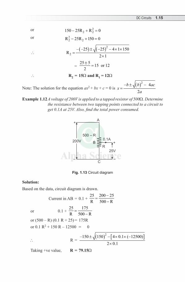
Example 1.12 A voltage of 200V is applied to a tapped resistor of 500W. Determine the resistance between two tapping points connected to a circuit to get 0.1A at 25V. Also, find the total power consumed.
+
–
200V
500 – R
+
–
25VR
0.1A
A
B
C
Fig. 1.13 Circuit diagram
Solution:Based on the data, circuit diagram is drawn.
Current in AB = 0.1 + 25 200 25R 500 R
−=
−
or 0.1 + 25 175R 500 R
=−
or (500 – R) (0.1 R + 25) = 175Ror 0.1 R2 + 150 R – 12500 = 0
∴ R = ( ) [ ]2–150 150 4 0.1 ( 12500)
2 0.1± − × × −
×
Taking +ve value, R = 79.15W
1.16 Electrical Engineering
Current in AB = 0.1 + 25 250.1R 79.15
= + = 0.42A
∴ Total power consumed, P = VI = 200 × 0.42 = 84W
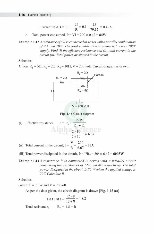
Example 1.13 A resistance of 5W is connected in series with a parallel combination of 2W and 10W. The total combination is connected across 200V supply. Find (i) the effective resistance and (ii) total current in the circuit (iii) Total power dissipated in the circuit.
Solution:Given: R1 = 5W, R2 = 2W, R3 = 10W, V = 200 volt. Circuit diagram is drawn.
+ –
V = 200 Volt
R = 83
R = 22
R = 21
Parallel
I
Fig. 1.14 Circuit diagram
(i) Effective resistance, R = R1 + 2 3
2 3
R RR R+
= 5 + 2 102 10×+
= 6.67W
(ii) Total current in the circuit, I = V 200R 6.67= = 30A
(iii) Total power dissipated in the circuit, P = I2RT = 302 × 6.67 = 6003W
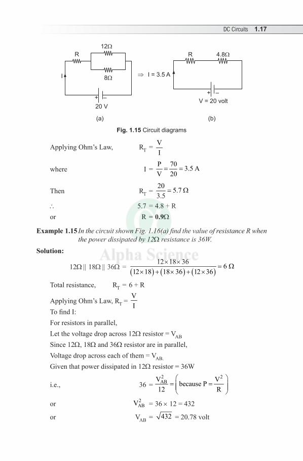
Example 1.14 A resistance R is connected in series with a parallel circuit comprising two resistances of 12W and 8W respectively. The total power dissipated in the circuit is 70 W when the applied voltage is 20V. Calculate R.
Solution:Given: P = 70 W and V = 20 volt
As per the data given, the circuit diagram is drawn [Fig. 1.15 (a)]
12W || 8W = 12 8 4.812 8
×= W
+Total resistance, RT = 4.8 + R
DC Circuits 1.17
R
12
8
20 V
I
+ –
R 4.8
V = 20 volt
+ –
I = 3.5 A
(a) (b)
Fig. 1.15 Circuit diagrams
Applying Ohm’s Law, RT = VI
where I = P 70 3.5 AV 20= =
Then RT = 20 5.73.5
= W
∴ 5.7 = 4.8 + Ror R = 0.9W
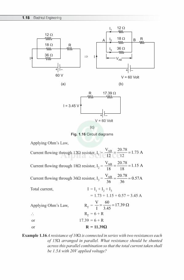
Example 1.15 In the circuit shown Fig. 1.16(a) find the value of resistance R when the power dissipated by 12W resistance is 36W.
Solution:
12W || 18W || 36W = ( ) ( ) ( )12 18 36 6
12 18 18 36 12 36× ×
= W× + × + ×
Total resistance, RT = 6 + R
Applying Ohm’s Law, RT = VI
To find I:For resistors in parallel, Let the voltage drop across 12W resistor = VAB
Since 12W, 18W and 36W resistor are in parallel, Voltage drop across each of them = VAB.
Given that power dissipated in 12W resistor = 36W
i.e., 36 = 2 2ABV Vbecause P
12 R
= =
or 2ABV = 36 × 12 = 432
or VAB = 432 = 20.78 volt
1.18 Electrical Engineering
12
18
36
R
I
60 VV = 60 Volt
12
18
36
A RB
I
+ – + –
I1
I2
I3
VAB
(a) (b)
R 17.39
V = 60 Volt
+ –
I = 3.45 V
(c)
Fig. 1.16 Circuit diagrams
Applying Ohm’s Law,
Current flowing through 12W resistor, I1 = ABV 20.78 1.73 A12 12
= =
Current flowing through 18W resistor, I2 = ABV 20.78 1.15 A18 18
= =
Current flowing through 36W resistor, I3 = ABV 20.78 0.57A36 36
= =
Total current, I = I1 + I2 + I3 = 1.73 + 1.15 + 0.57 = 3.45 A
Applying Ohm’s Law, RT = V 60 17.39 I 3.45= = W
∴ RT = 6 + R or 17.39 = 6 + R or R=11.39Ω
Example 1.16 A resistance of 10W is connected in series with two resistances each of 15W arranged in parallel. What resistance should be shunted across this parallel combination so that the total current taken shall be 1.5A with 20V applied voltage?
DC Circuits 1.19
Solution:
As two 15W resistances are connected in parallel, 15W || 15W = 152
= 7.5W
Let R be the resistance to be shunted across parallel combination.
Then, total resistance, RT = VI
i.e., 10 + 7.5 R 20
7.5 R 1.5=
+
or 7.5 R 207.5 R 1.5
=+
–10
or 7.5 R 57.5 R 1.5
=+
or (7.5 + R) × 5 = 7.5 R × 1.5or R = 6W
Example 1.17 A battery supplies 48.4 mA to a 25W load and 25.9 mA to a 50W load. Determine the emf and the internal resistance, assuming that both will remain constant. Also, find terminal voltage of the battery when it is connected to a load of 40W.
Solution:Let E = EMF of the battery in mV and r = internal resistance of battery in ohm
Then, E
25 + r = 48.3 mA and E 25.9 mA
50=
+ r
∴ 5025
++
rr =
48.325.9
= 1.865
or (50 + r) = 1.865 (25 + r)or (50 + r) = 46.625 + 1.865 ror 0.865 r = 3.38or r = 3.9W∴ E = 48.3 mA (25 + 3.9) = 1390mV = 1.39VWith load of RL= 40W,
Terminal voltage, V = E × L
L
RR + r
= 401.39 1.27 V
40 3.9× =
+ = 1.27V
1.20 Electrical Engineering
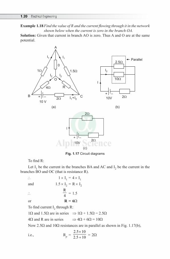
Example 1.18 Find the value of R and the current flowing through it in the network shown below when the current is zero in the branch OA.
Solution: Given that current in branch AO is zero. Thus A and O are at the same potential.
A
B C2
R
10 V
4
1 1.5
I1I1
I2I2
+ –
O
02.5
10
Parallel
I
I2
10V 2
+ –
I +I1 2
(a) (b)
2
2
10V
+ –
I
(c)Fig. 1.17 Circuit diagrams
To find R: Let I1 be the current in the branches BA and AC and I2 be the current in the
branches BO and OC (that is resistance R).∴ 1 × I1 = 4 × I1
and 1.5 × I2 = R × I2
∴ R4 = 1.5
or R = 6WTo find current I2 through R:1W and 1.5W are in series ⇒ 1W + 1.5W = 2.5W4W and R are in series ⇒ 4W + 6W = 10WNow 2.5W and 10W resistances are in parallel as shown in Fig. 1.17(b),
i.e., Rp = 2.5 102.5 10
×+ = 2W
DC Circuits 1.21
Total current, I = 102 2+
= 2.5A [as shown in Fig. 1.17(c)]
Therefore, referring to Fig. 1.17(b), current through R is
I2 = 2.52.5
10 2.5×
+ = 0.5A
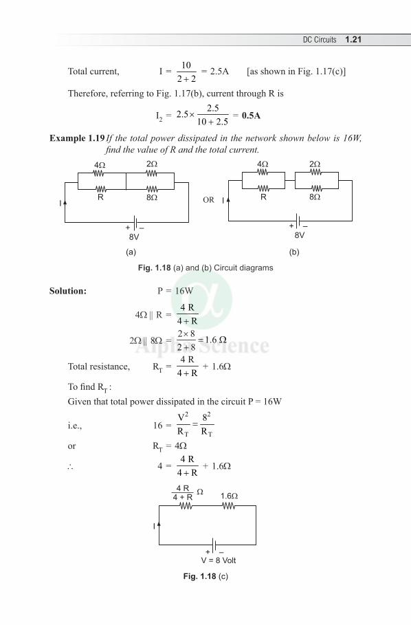
Example 1.19 If the total power dissipated in the network shown below is 16W, find the value of R and the total current.
4 2
8R
8V
I
4 2
8RI
8V+ – + –
OR
(a) (b)
Fig. 1.18 (a) and (b) Circuit diagrams
Solution: P = 16W
4W || R = 4 R
4 R+
2W || 8W = 2 8 1.6 2 8×
= W+
Total resistance, RT = 4 R
4 R+ + 1.6W
To find RT :Given that total power dissipated in the circuit P = 16W
i.e., 16 = 2 2
T T
V 8R R
=
or RT = 4W
∴ 4 = 4 R
4 R+ + 1.6W
4 R4 + R
1.6
I
+ –V = 8 Volt
Fig. 1.18 (c)
1.22 Electrical Engineering
or R = 6W Applying Ohm’s Law,
Total current, I = T
V 8R 4
= = 2A
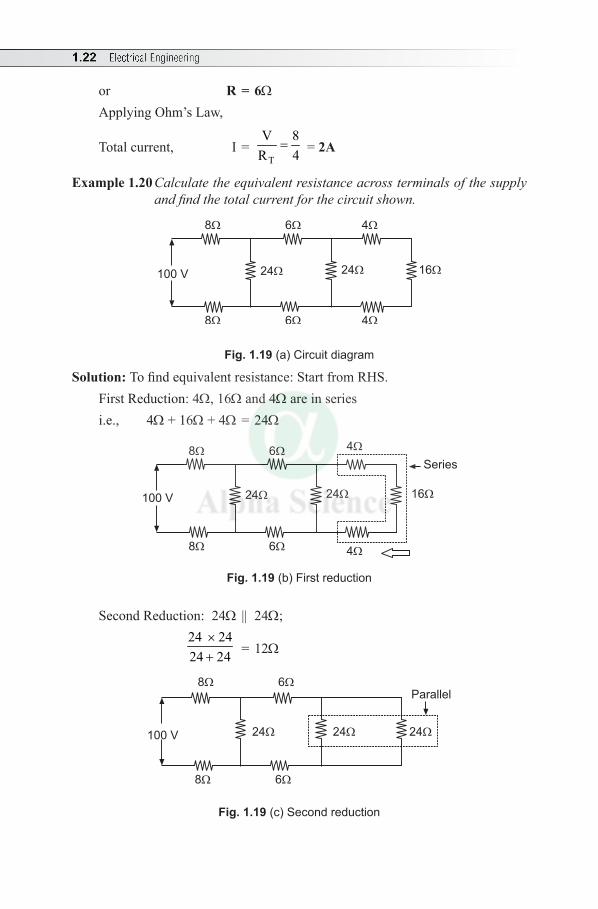
Example 1.20 Calculate the equivalent resistance across terminals of the supply and find the total current for the circuit shown.
8 6 4
8 6 4
100 V 24 24 16
Fig. 1.19 (a) Circuit diagram
Solution: To find equivalent resistance: Start from RHS.First Reduction: 4W, 16W and 4W are in series i.e., 4W + 16W + 4W = 24W
8 64
8 6 4
100 V 24 24 16
Series
Fig. 1.19 (b) First reduction
Second Reduction: 24W || 24W;
24 2424 24
×+ = 12W
8 6
8 6
24 24 24100 V
Parallel
Fig. 1.19 (c) Second reduction
DC Circuits 1.23
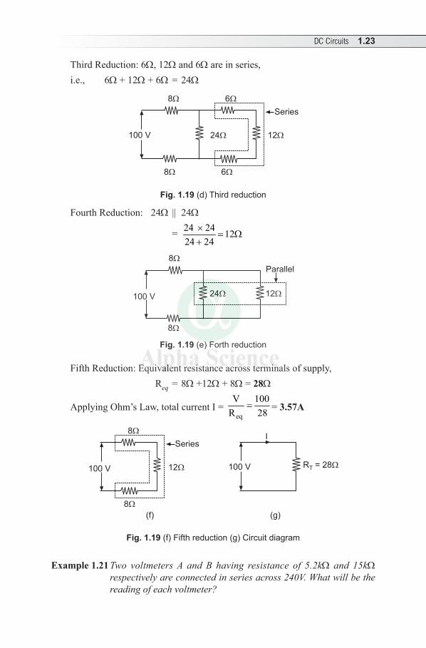
Third Reduction: 6W, 12W and 6W are in series, i.e., 6W + 12W + 6W = 24W
100 V
8 6
8 6
24 12
Series
Fig. 1.19 (d) Third reduction
Fourth Reduction: 24W || 24W
= 24 24 1224 24
×= W
+
8
8
100 V 24 12
Parallel
Fig. 1.19 (e) Forth reduction
Fifth Reduction: Equivalent resistance across terminals of supply, Req = 8W +12W + 8W = 28W
Applying Ohm’s Law, total current I = eq
V 100R 28
= = 3.57A
100 V
8
8
12
Series
100 V R = 28T
I
(f) (g)
Fig. 1.19 (f) Fifth reduction (g) Circuit diagram
Example 1.21 Two voltmeters A and B having resistance of 5.2kW and 15kW respectively are connected in series across 240V. What will be the reading of each voltmeter?
1.24 Electrical Engineering
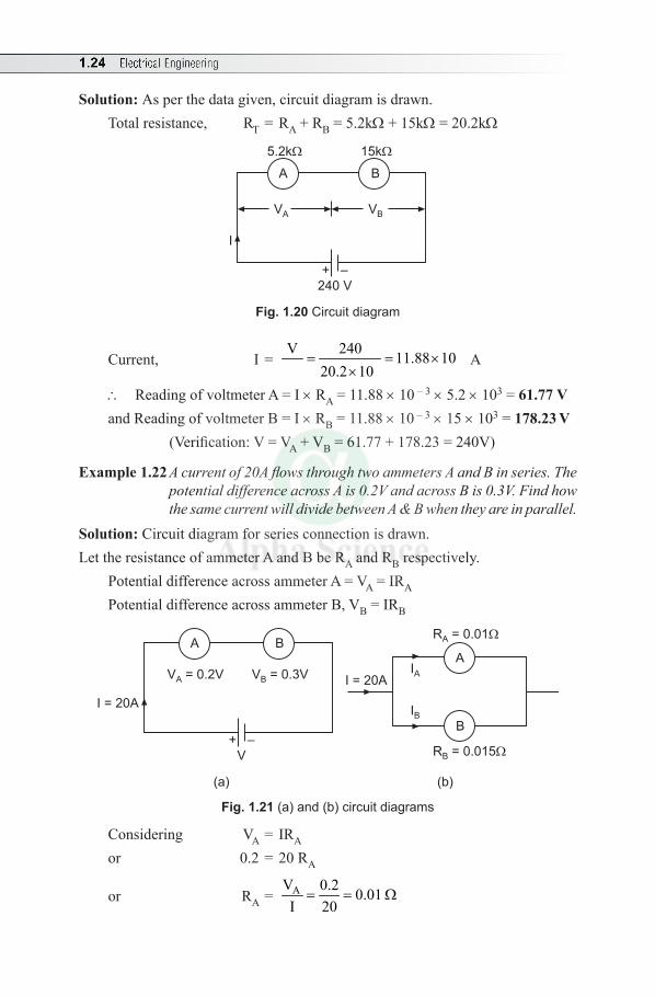
Solution: As per the data given, circuit diagram is drawn.Total resistance, RT = RA + RB = 5.2kW + 15kW = 20.2kW
BA
5.2k 15k
+ –
I
VA VB
240 V
Fig. 1.20 Circuit diagram
Current, I = V 240 11.88 10
20.2 10= = ×
×A
∴ Reading of voltmeter A = I × RA = 11.88 × 10 – 3 × 5.2 × 103 = 61.77 Vand Reading of voltmeter B = I × RB = 11.88 × 10 – 3 × 15 × 103 = 178.23 V (Verification: V = VA + VB = 61.77 + 178.23 = 240V)
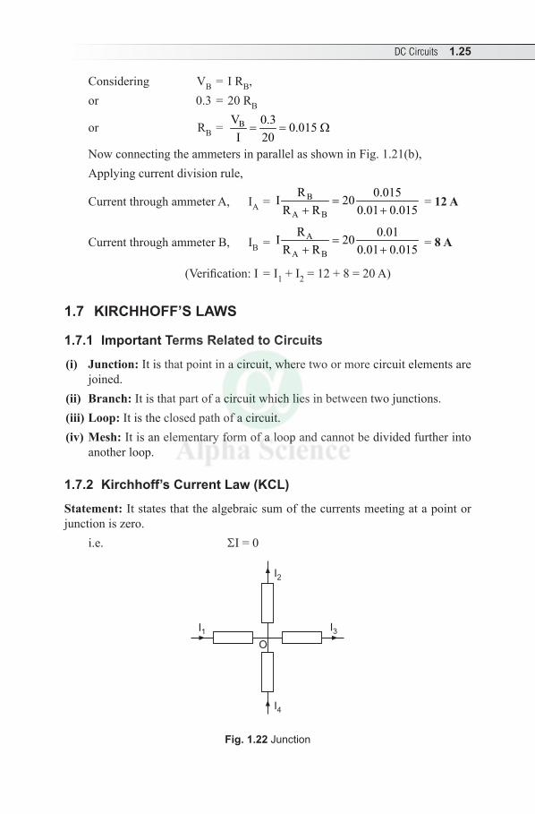
Example 1.22 A current of 20A flows through two ammeters A and B in series. The potential difference across A is 0.2V and across B is 0.3V. Find how the same current will divide between A & B when they are in parallel.
Solution: Circuit diagram for series connection is drawn.Let the resistance of ammeter A and B be RA and RB respectively.
Potential difference across ammeter A = VA = IRA Potential difference across ammeter B, VB = IRB
BA
+ –
I = 20A
V
V = 0.2VA V = 0.3VB
A
B
I = 20AIA
IB
R = 0.01A
R = 0.015B
(a) (b)
Fig. 1.21 (a) and (b) circuit diagrams
Considering VA = IRA
or 0.2 = 20 RA
or RA = AV 0.2 0.01 I 20
= = W
DC Circuits 1.25
Considering VB = I RB,or 0.3 = 20 RB
or RB = BV 0.3 0.015 I 20= = W
Now connecting the ammeters in parallel as shown in Fig. 1.21(b),Applying current division rule,
Current through ammeter A, IA = B
A B
R 0.015I 20R R 0.01 0.015
=+ +
= 12 A
Current through ammeter B, IB = A
A B
R 0.01I 20R R 0.01 0.015
=+ + = 8 A
(Verification: I = I1 + I2 = 12 + 8 = 20 A)
1.7 KIRCHHOFF’S LAWS
1.7.1 Important Terms Related to Circuits
(i) Junction: It is that point in a circuit, where two or more circuit elements are joined.
(ii) Branch: It is that part of a circuit which lies in between two junctions.(iii) Loop: It is the closed path of a circuit.(iv) Mesh: It is an elementary form of a loop and cannot be divided further into
another loop.
1.7.2 Kirchhoff’s Current Law (KCL)
Statement: It states that the algebraic sum of the currents meeting at a point or junction is zero.
i.e. SI = 0
I2
I3I1
I4
O
Fig. 1.22 Junction
1.26 Electrical Engineering
Explanation: Let currents I1, I2 and I4 are the incoming currents flowing towards the junction O and I3 is outgoing current, flowing away from the junction O.
Incoming currents are taken as positive and outgoing currents as negative.Applying KCL at junction O, I1 + I2 + ( – I3) + I4 = 0 ...(1.1)Equation (1.1) can also be written as I1 + I2 + I4 = I3
Therefore, sum of the incoming currents is equal to the sum of the outgoing currents.
Important Point
It is another version of principle of conservation of charge.
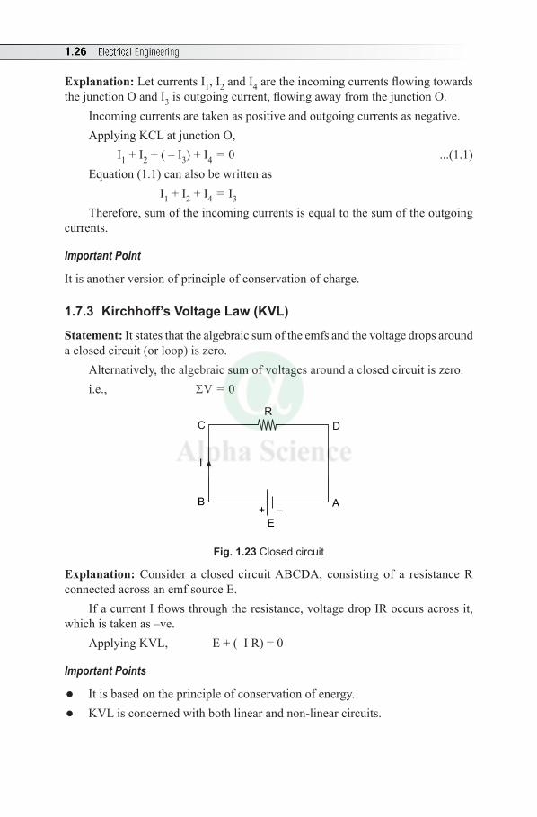
1.7.3 Kirchhoff’s Voltage Law (KVL)
Statement: It states that the algebraic sum of the emfs and the voltage drops around a closed circuit (or loop) is zero.
Alternatively, the algebraic sum of voltages around a closed circuit is zero.i.e., SV = 0
E
+ –
R
I
AB
C D
Fig. 1.23 Closed circuit
Explanation: Consider a closed circuit ABCDA, consisting of a resistance R connected across an emf source E.
If a current I flows through the resistance, voltage drop IR occurs across it, which is taken as –ve.
Applying KVL, E + (–I R) = 0
Important Points
l It is based on the principle of conservation of energy.l KVL is concerned with both linear and non-linear circuits.
DC Circuits 1.27
1.7.4 Sign Convention
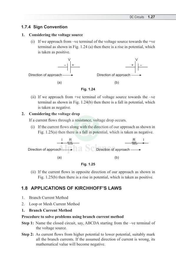
1. Considering the voltage source(i) If we approach from –ve terminal of the voltage source towards the +ve
terminal as shown in Fig. 1.24 (a) then there is a rise in potential, which is taken as positive.
+ –
V
Direction of approach Direction of approach
+–
V
(a) (b)
Fig. 1.24
(ii) If we approach from +ve terminal of voltage source towards the –ve terminal as shown in Fig. 1.24(b) then there is a fall in potential, which is taken as negative.
2. Considering the voltage drop If a current flows through a resistance, voltage drop occurs.
(i) If the current flows along with the direction of our approach as shown in Fig. 1.25(a) then there is a fall in potential, which is taken as negative.
Direction of approach Direction of approach
IRI R
(a) (b)
Fig. 1.25
(ii) If the current flows in opposite direction of our approach as shown in Fig. 1.25(b) then there is a rise in potential, which is taken as positive.
1.8 APPLICATIONS OF KIRCHHOFF’S LAWS
1. Branch Current Method2. Loop or Mesh Current Method1. Branch Current MethodProcedure to solve problems using branch current methodStep 1: Name the closed circuit, say, ABCDA starting from the –ve terminal of
the voltage source. Step 2: As current flows from higher potential to lower potential, suitably mark
all the branch currents. If the assumed direction of current is wrong, its mathematical value will become negative.
1.28 Electrical Engineering
Step 3: Apply KCL at a point or junction if different currents meet at a junction.Step 4: Assume a suitable direction of approach, either clockwise direction or
anticlockwise direction as per your convenience and apply KVL to the closed circuits as per the requirement and write the corresponding equations (the number of equations should be minimum).
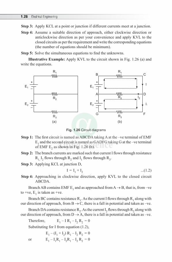
Step 5: Solve the simultaneous equations to find the unknowns.Illustrative Example: Apply KVL to the circuit shown in Fig. 1.26 (a) and
write the equations.
R2
E1
E2
+
–
+
–
B
GR3
R1C
F
DA
I
I1
R2
R3
R1
E1
E2
+
–
+
–
I2
(a) (b)
Fig. 1.26 Circuit diagrams
Step 1: The first circuit is named as ABCDA taking A at the –ve terminal of EMF E1 and the second circuit is named as GADFG taking G at the –ve terminal of EMF E2 as shown in Fig. 1.26 (b).
Step 2: The branch currents are marked such that current I flows through resistance R1, I2 flows through R2 and I1 flows through R3.
Step 3: Applying KCL at junction D, I = I1 + I2 ...(1.2)
Step 4: Approaching in clockwise direction, apply KVL to the closed circuit ABCDA.
Branch AB contains EMF E1 and as approached from A → B, that is, from –ve to +ve, E1 is taken as +ve.
Branch BC contains resistance R1. As the current I flows through R1 along with our direction of approach, from B → C, there is a fall in potential and taken as –ve.
Branch DA contains resistance R2. As the current I2 flows through R2 along with our direction of approach, from D → A, there is a fall in potential and taken as –ve.
Therefore, E1 – I R1 – I2 R2 = 0Substituting for I from equation (1.2), E1 – (I1 + I2) R1 – I2 R2 = 0or E1 – I1R1 – I2R1 – I2 R2 = 0
DC Circuits 1.29
or E1 – I1R1 – I2 (R1 + R2) = 0or – I1R1 – I2 (R1 + R2) = –E1 ...(1.3)Similarly applying KVL to the closed circuit GADFG taking E2 as +ve. E2 + I2R2 – I1R3 = 0 or I2R2 – I1R3 = –E2 ...(1.4)Applying KVL to the closed circuit GABCDFG, E2 + E1 – I R1 – I1 R3 = 0 Substituting for I from equation (1.2), E2 + E1 – (I1 + I2) R1 – I1 R3 = 0or E2 + E1 – I1 R1 – I2R1 – I1 R3 = 0or E1 + E2 – I1(R1 + R3) – I2R1 = 0or – I1(R1 + R3) – I2R1 = –E1 – E2 ...(1.5)
Solved Examples
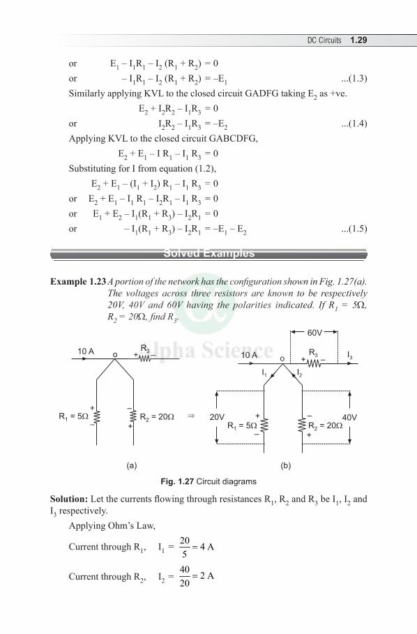
Example 1.23 A portion of the network has the configuration shown in Fig. 1.27(a). The voltages across three resistors are known to be respectively 20V, 40V and 60V having the polarities indicated. If R1 = 5W, R2 = 20W, find R3.
+
o
–+20V
10 A o + –
– 40V
60V
– +
R3 R3
I1 I2
+ –10 A
R = 51 R = 202
+
–
I3
R = 202 R = 51
(a) (b)
Fig. 1.27 Circuit diagrams
Solution: Let the currents flowing through resistances R1, R2 and R3 be I1, I2 and I3 respectively.
Applying Ohm’s Law,
Current through R1, I1 = 20 4 A5=
Current through R2, I2 = 40 2 A20
=
1.30 Electrical Engineering
Applying KCL at point O, 10 – I1 + I2 – I3 = 0i.e., 10 – 4 + 2 – I3 = 0or I3 = 8 A
∴ R3 = 3
60 60I 8
= = 7.5 W
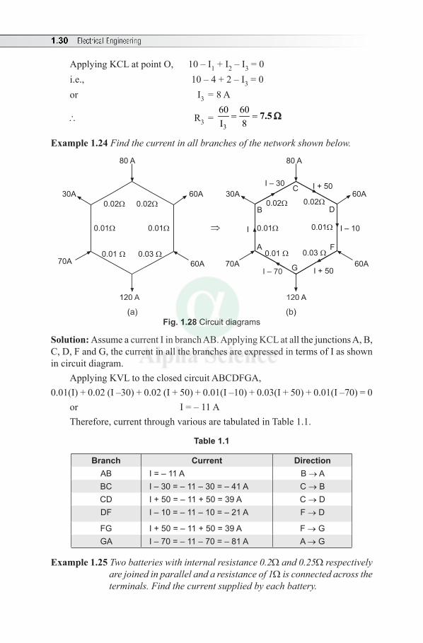
Example 1.24 Find the current in all branches of the network shown below.
C
D
FA
B0.02
0.01
0.03 0.01
0.01
0.02
30A
I – 30 I + 5060A
60A70A
I I – 10
80 A
0.02
0.01
0.03 0.01
0.01
0.02
60A
60A70A
80 A
30A
G I + 50I – 70
120 A120 A
(a) (b)Fig. 1.28 Circuit diagrams
Solution: Assume a current I in branch AB. Applying KCL at all the junctions A, B, C, D, F and G, the current in all the branches are expressed in terms of I as shown in circuit diagram.
Applying KVL to the closed circuit ABCDFGA,0.01(I) + 0.02 (I –30) + 0.02 (I + 50) + 0.01(I –10) + 0.03(I + 50) + 0.01(I –70) = 0
or I = – 11 ATherefore, current through various are tabulated in Table 1.1.
Table 1.1
Branch Current DirectionAB I = – 11 A B → ABC I – 30 = – 11 – 30 = – 41 A C → BCD I + 50 = – 11 + 50 = 39 A C → DDF I – 10 = – 11 – 10 = – 21 A F → D
FG I + 50 = – 11 + 50 = 39 A F → GGA I – 70 = – 11 – 70 = – 81 A A → G
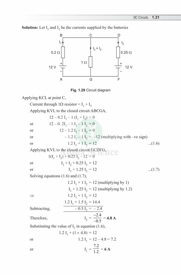
Example 1.25 Two batteries with internal resistance 0.2W and 0.25W respectively are joined in parallel and a resistance of 1W is connected across the terminals. Find the current supplied by each battery.
DC Circuits 1.31
Solution: Let I1 and I2 be the currents supplied by the batteries
0.25
12 V
F
D
I + I2 2
+
–
GA
CB
0.2
+
–
1
I2I1
12 V
Fig. 1.29 Circuit diagram
Applying KCL at point C,Current through 1W resistor = I1 + I2
Applying KVL to the closed circuit ABCGA, 12 – 0.2 I1 – 1 (I1 + I2) = 0or 12 – 0. 2I1 – 1 I1 – 1 I2 = 0or 12 – 1.2 I1 – 1 I2 = 0or – 1.2 I1 – 1 I2 = –12 (multiplying with –ve sign)or 1.2 I1 + 1 I2 = 12 ...(1.6)Applying KVL to the closed circuit GCDFG, 1(I1 + I2) + 0.25 I2 – 12 = 0or I1 + I2 + 0.25 I2 = 12or I1 + 1.25 I2 = 12 ...(1.7) Solving equations (1.6) and (1.7), 1.2 I1 + 1 I2 = 12 (multiplying by 1) I1 + 1.25 I2 = 12 (multiplying by 1.2) ⇒ 1.2 I1 + 1 I2 = 12 1.2 I1 + 1.5 I2 = 14.4Subtracting, – 0.5 I2 = – 2.4
Therefore, I2 = 2.40.5
−−
= 4.8 A
Substituting the value of I2 in equation (1.6), 1.2 I1 + (1 × 4.8) = 12 or 1.2 I1 = 12 – 4.8 = 7.2
or I1 = 7.21.2 = 6 A
1.32 Electrical Engineering
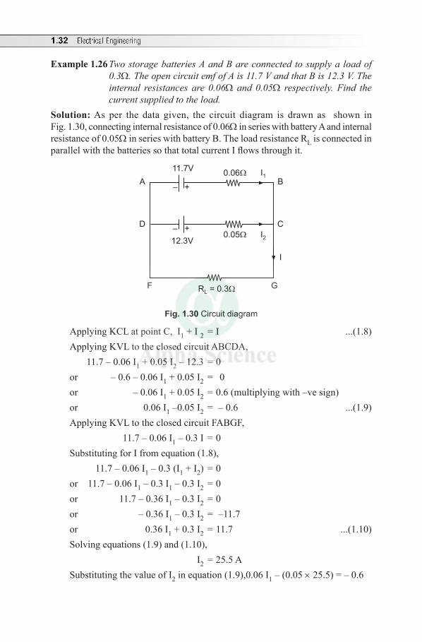
Example 1.26 Two storage batteries A and B are connected to supply a load of 0.3W. The open circuit emf of A is 11.7 V and that B is 12.3 V. The internal resistances are 0.06W and 0.05W respectively. Find the current supplied to the load.
Solution: As per the data given, the circuit diagram is drawn as shown in Fig. 1.30, connecting internal resistance of 0.06W in series with battery A and internal resistance of 0.05W in series with battery B. The load resistance RL is connected in parallel with the batteries so that total current I flows through it.
B
C
I
A
D
F G
12.3V0.05 I2
I10.0611.7V
R = 0.3L
– +
– +
Fig. 1.30 Circuit diagram
Applying KCL at point C, I1 + I 2 = I ...(1.8)Applying KVL to the closed circuit ABCDA, 11.7 – 0.06 I1 + 0.05 I2 – 12.3 = 0or – 0.6 – 0.06 I1 + 0.05 I2 = 0or – 0.06 I1 + 0.05 I2 = 0.6 (multiplying with –ve sign)or 0.06 I1 –0.05 I2 = – 0.6 ...(1.9)Applying KVL to the closed circuit FABGF, 11.7 – 0.06 I1 – 0.3 I = 0Substituting for I from equation (1.8), 11.7 – 0.06 I1 – 0.3 (I1 + I2) = 0or 11.7 – 0.06 I1 – 0.3 I1 – 0.3 I2 = 0or 11.7 – 0.36 I1 – 0.3 I2 = 0or – 0.36 I1 – 0.3 I2 = –11.7 or 0.36 I1 + 0.3 I2 = 11.7 ...(1.10)Solving equations (1.9) and (1.10), I2 = 25.5 ASubstituting the value of I2 in equation (1.9),0.06 I1 – (0.05 × 25.5) = – 0.6
DC Circuits 1.33
or 0.06 I1 = 0.675
or I1 = 0.675 11.25 A0.06
=
According to equation (1.8), current supplied to the load is I = I1 + I2 = 11.25 + 25.5 = 36.75 A
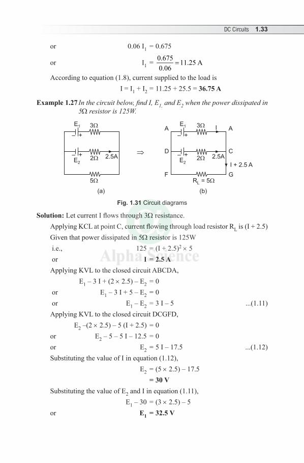
Example 1.27 In the circuit below, find I, E1, and E2 when the power dissipated in 5W resistor is 125W.
E1 3
– +
E2
– +2
2.5A
5
E1 3
– +
E2
– +2
2.5A
I
R = 5L
I + 2.5 A
A A
C
G
D
F
(a) (b)
Fig. 1.31 Circuit diagrams
Solution: Let current I flows through 3W resistance.Applying KCL at point C, current flowing through load resistor RL is (I + 2.5)Given that power dissipated in 5W resistor is 125W i.e., 125 = (I + 2.5)2 × 5 or I = 2.5 AApplying KVL to the closed circuit ABCDA, E1 – 3 I + (2 × 2.5) – E2 = 0 or E1 – 3 I + 5 – E2 = 0 or E1 – E2 = 3 I – 5 ...(1.11)Applying KVL to the closed circuit DCGFD, E2 –(2 × 2.5) – 5 (I + 2.5) = 0or E2 – 5 – 5 I – 12.5 = 0or E2 = 5 I – 17.5 ...(1.12)Substituting the value of I in equation (1.12), E2 = (5 × 2.5) – 17.5 = 30 VSubstituting the value of E2 and I in equation (1.11), E1 – 30 = (3 × 2.5) – 5or E1 = 32.5 V
1.34 Electrical Engineering
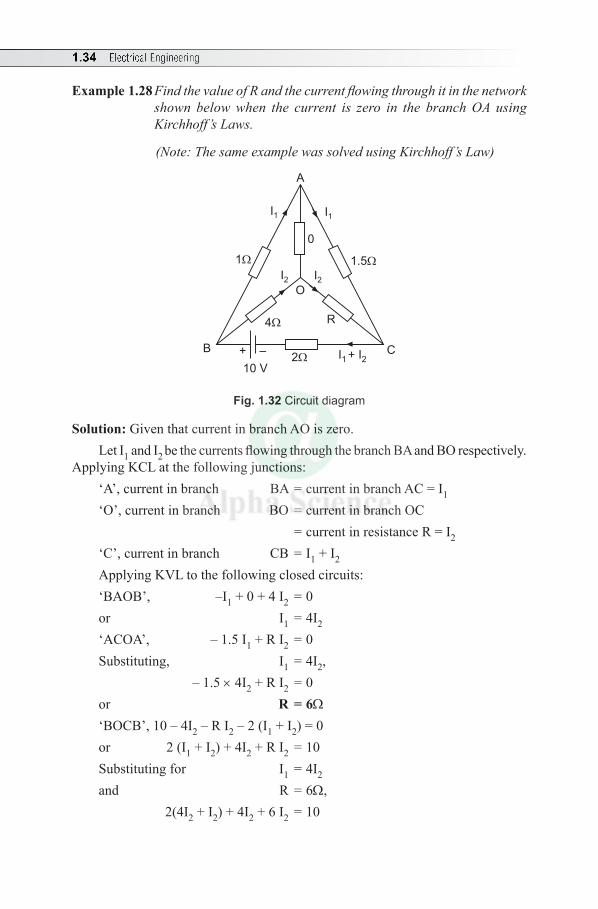
Example 1.28 Find the value of R and the current flowing through it in the network shown below when the current is zero in the branch OA using Kirchhoff’s Laws.
(Note: The same example was solved using Kirchhoff’s Law)
A
B C2
R
10 V
4
1 1.5
I1I1
I2I2
+ –
O
I + I1 2
0
Fig. 1.32 Circuit diagram
Solution: Given that current in branch AO is zero. Let I1 and I2 be the currents flowing through the branch BA and BO respectively.
Applying KCL at the following junctions:‘A’, current in branch BA = current in branch AC = I1 ‘O’, current in branch BO = current in branch OC = current in resistance R = I2
‘C’, current in branch CB = I1 + I2
Applying KVL to the following closed circuits:‘BAOB’, –I1 + 0 + 4 I2 = 0 or I1 = 4I2 ‘ACOA’, – 1.5 I1 + R I2 = 0
Substituting, I1 = 4I2, – 1.5 × 4I2 + R I2 = 0or R = 6W‘BOCB’, 10 – 4I2 – R I2 – 2 (I1 + I2) = 0 or 2 (I1 + I2) + 4I2 + R I2 = 10Substituting for I1 = 4I2
and R = 6W, 2(4I2 + I2) + 4I2 + 6 I2 = 10
DC Circuits 1.35
or (2 × 5 I2) + 10 I2 = 10or 20 I2 = 10or I2 = 0.5 A
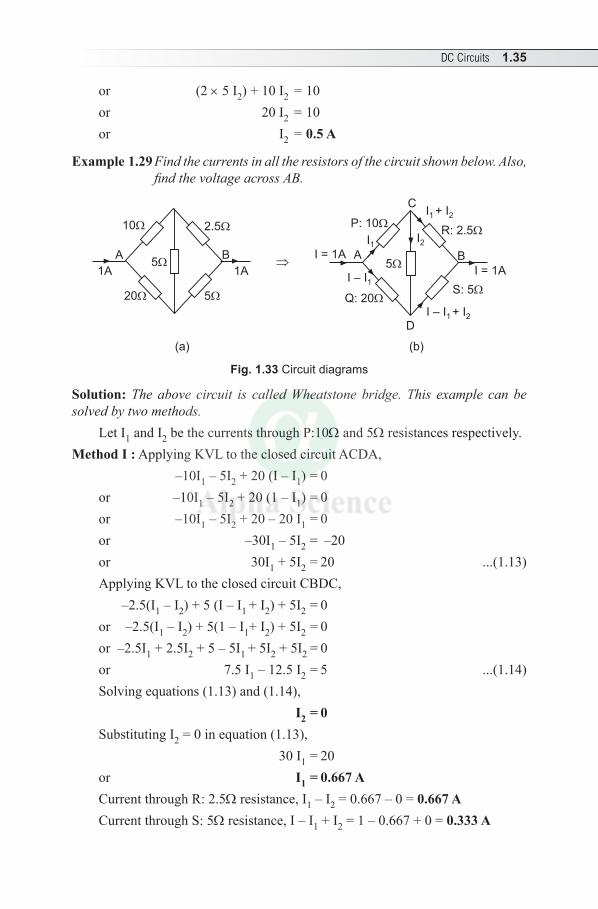
Example 1.29 Find the currents in all the resistors of the circuit shown below. Also, find the voltage across AB.
10 2.5
520
B
1A1A
A5
P: 10R: 2.5
S: 5
Q: 20
B
I = 1A
I = 1A A5
C
I2
D
I + I1 2
I – I + I1 2
I – I1
I1
(a) (b)
Fig. 1.33 Circuit diagrams
Solution: The above circuit is called Wheatstone bridge. This example can be solved by two methods.
Let I1 and I2 be the currents through P:10W and 5W resistances respectively.Method I : Applying KVL to the closed circuit ACDA,
–10I1 – 5I2 + 20 (I – I 1) = 0or –10I1 – 5I2 + 20 (1 – I 1) = 0or –10I1 – 5I2 + 20 – 20 I 1 = 0or –30I1 – 5I2 = –20or 30I1 + 5I2 = 20 ...(1.13)Applying KVL to the closed circuit CBDC, –2.5(I1 – I2) + 5 (I – I 1 + I2) + 5I2 = 0or –2.5(I1 – I2) + 5(1 – I 1+ I2) + 5I2 = 0 or –2.5I1 + 2.5I2 + 5 – 5I 1 + 5I2 + 5I2 = 0 or 7.5 I1 – 12.5 I2 = 5 ...(1.14)Solving equations (1.13) and (1.14), I2 = 0Substituting I2 = 0 in equation (1.13), 30 I1 = 20or I1 = 0.667 ACurrent through R: 2.5W resistance, I1 – I2 = 0.667 – 0 = 0.667 ACurrent through S: 5W resistance, I – I1 + I2 = 1 – 0.667 + 0 = 0.333 A
1.36 Electrical Engineering
∴ Voltage drop across AB, VAB = I × RT
To find total resistance RT: As I2 = 0, 10W and 2.5W resistances are in series = 12.5W. Also, 20W and 5W resistances are in series = 25W
RT = 12.5W || 25W = 12.5 25 8.3312.5 25
×= W
+∴ VAB = 1 × 8.33 = 8.33 V
Method II: If the bridge is balanced, PQ
= RS
i.e., 1020
= 2.55
or 0.5 = 0.5Then, I2 = 0Therefore, 10W and 2.5W resistances are in series ⇒ 10W + 2.5W = 12.5W,20W and 5W resistances are in series ⇒ 20W + 5W = 25W.Now 12.5W and 25W resistances are in parallel.Let x and y be the currents, which flow through 12.5W and 25W respectively
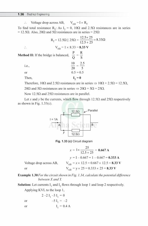
as shown in Fig. 1.33(c).
B
I = 1A
A
y
12.5
12.5
xParallel
Fig. 1.33 (c) Circuit diagram
x = 251
12.5 25×
+ = 0.667 A
y = I – 0.667 = 1 – 0.667 = 0.333 AVoltage drop across AB, VAB = x × 12.5 = 0.667 × 12.5 = 8.33 V or VAB = y × 25 = 0.333 × 25 = 8.33 V
Example 1.30 For the circuit shown in Fig. 1.34, calculate the potential difference between X and Y.
Solution: Let currents I1 and I2 flows through loop 1 and loop 2 respectively.Applying KVL to the loop 1, 2 –2 I1 –3 I1 = 0or –5 I1 = –2or I1 = 0.4 A
DC Circuits 1.37
–+
–+
–+
6 V
A
X
Y
B5 V
Loop 2Loop 1
2 V
I1 2
6 10
I2
3
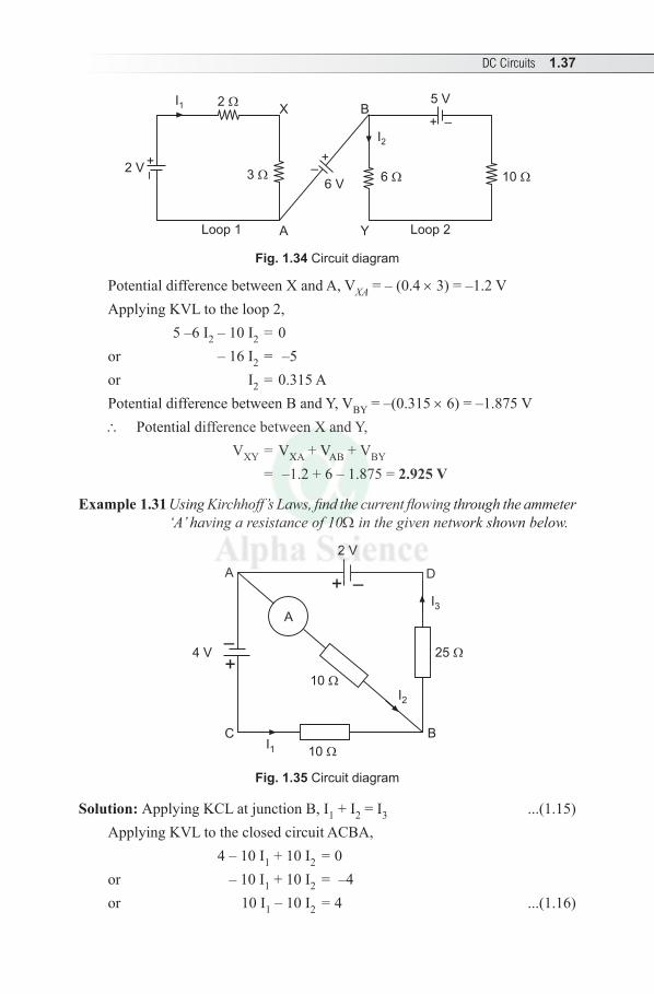
Fig. 1.34 Circuit diagram
Potential difference between X and A, VXA = – (0.4 × 3) = –1.2 VApplying KVL to the loop 2, 5 –6 I2 – 10 I2 = 0or – 16 I2 = –5or I2 = 0.315 APotential difference between B and Y, VBY = –(0.315 × 6) = –1.875 V∴ Potential difference between X and Y, VXY = VXA + VAB + VBY
= –1.2 + 6 – 1.875 = 2.925 V
Example 1.31 Using Kirchhoff’s Laws, find the current flowing through the ammeter ‘A’ having a resistance of 10W in the given network shown below.
A
–+
25
BC
4 V
A D
2 V
10
10
I1
I2
I3
–+
Fig. 1.35 Circuit diagram
Solution: Applying KCL at junction B, I1 + I2 = I3 ...(1.15) Applying KVL to the closed circuit ACBA, 4 – 10 I 1 + 10 I2 = 0or – 10 I 1 + 10 I2 = –4or 10 I 1 – 10 I2 = 4 ...(1.16)
1.38 Electrical Engineering
Applying KVL to the closed circuit DABD, 2 – 10 I 2 – 25 I3 = 0Substituting for I3 from equation (1.15), 2 – 10 I 2 – 25 (I1 + I2) = 0 or – 10 I 2 – 25 I1 – 25 I2 = –2or – 25 I1 – 35 I2 = –2or 25 I1 + 35 I2 = 2 ...(1.17)Solving equations (1.16) and (1.17), I1 = 0.2667 A and I2 = –0.1333 ATherefore, current through ammeter is I2 = 0.1333 A and its direction is from
B to A.2. Loop or Mesh current method: It is also called Maxwell’s loop current
method. In this method continuous currents are assumed in various loops called loop currents. It uses KVL. This method is applicable for the networks having large number of junctions and simplifies the calculations.
(Note: Equations can be written in matrix form and solved using Cramer’s rule)Procedure to solve problems using loop current methodStep 1: Identify the loops and name them.Step 2: Loop currents are assumed in each loop.Step 3: Same sign conventions can be followed. Step 4: Apply KVL to each loop and write equations.Step 5: Solve the simultaneous equations to find the unknowns.
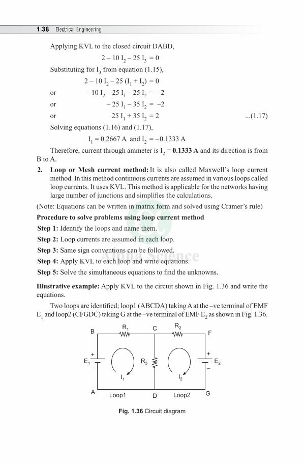
Illustrative example: Apply KVL to the circuit shown in Fig. 1.36 and write the equations.
Two loops are identified; loop1 (ABCDA) taking A at the –ve terminal of EMF E1 and loop2 (CFGDC) taking G at the –ve terminal of EMF E2 as shown in Fig. 1.36.
+
–
+
–
A
BC
D
F
GLoop1 Loop2
I1 I2
R1R2
R3 E2E1
Fig. 1.36 Circuit diagram
DC Circuits 1.39
Two loop currents, I1 and I2 are assumed in loop1 and loop2 respectively. Important point to be observed is that the branch CD containing resistance R3 carries two loop currents I1 and I2.
Sign convention is same as discussed in branch current method.Approaching in clockwise direction, apply KVL to the loop1. As current I2
flows through R3, there is a rise in voltage drop and taken as +ve. E1 – I1 R1 – I1 R3 + I2 R3 = 0 or – I1(R1 + R2) + I2 R3 = –E1
Similarly applying KVL to the loop 2, (as current I1 flows through R3, there is a rise in voltage drop and taken as +ve).
– I2 R2 – E2 – I2 R3 + I1 R3 = 0or I1 R3 – I2 (R2 + R3) = E2
Solved Examples
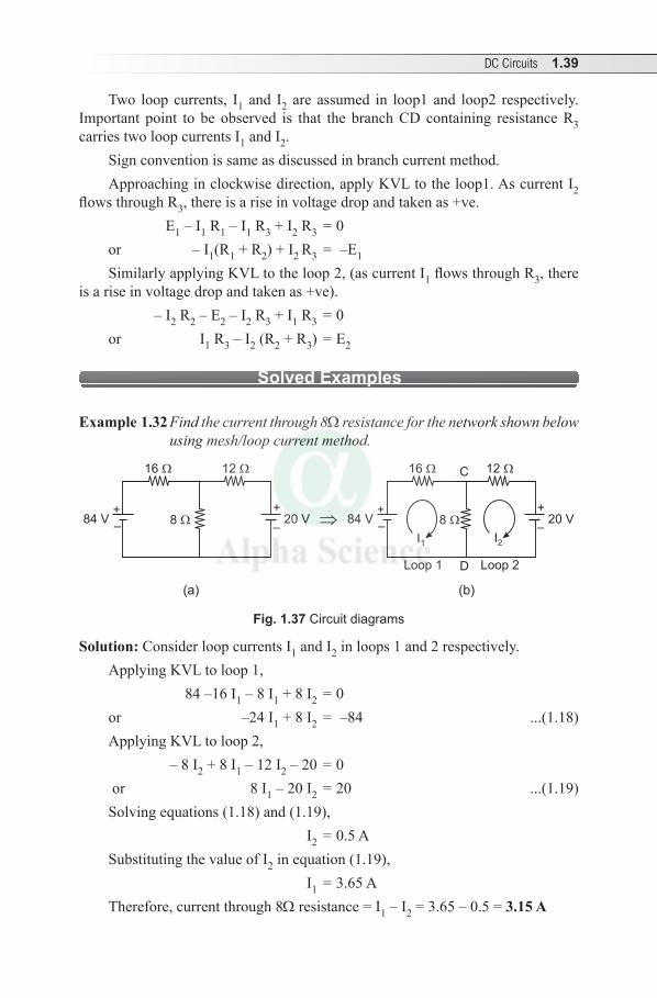
Example 1.32 Find the current through 8W resistance for the network shown below using mesh/loop current method.
+
–
+
–
C
DLoop 1 Loop 2
I1 I2
16 12
20 V84 V+
–
+
–
16 12
20 V84 V 8 8
(a) (b)
Fig. 1.37 Circuit diagrams
Solution: Consider loop currents I1 and I2 in loops 1 and 2 respectively.Applying KVL to loop 1, 84 –16 I1 – 8 I1 + 8 I2 = 0or –24 I1 + 8 I2 = –84 ...(1.18)Applying KVL to loop 2, – 8 I2 + 8 I1 – 12 I2 – 20 = 0 or 8 I1 – 20 I2 = 20 ...(1.19)Solving equations (1.18) and (1.19), I2 = 0.5 ASubstituting the value of I2 in equation (1.19), I1 = 3.65 ATherefore, current through 8W resistance = I1 – I2 = 3.65 – 0.5 = 3.15 A
1.40 Electrical Engineering
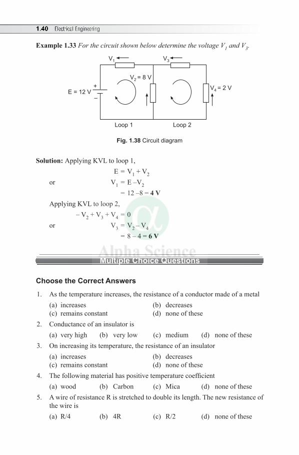
Example 1.33 For the circuit shown below determine the voltage V1 and V3.
+
–
Loop 1 Loop 2
V1 V3
V = 8 V2
V = 2 V4E = 12 V
Fig. 1.38 Circuit diagram
Solution: Applying KVL to loop 1, E = V1 + V2
or V1 = E –V2
= 12 –8 = 4 VApplying KVL to loop 2, – V2 + V3 + V4 = 0or V3 = V2 – V4
= 8 – 4 = 6 V
Multiple Choice Questions
Choose the Correct Answers
1. As the temperature increases, the resistance of a conductor made of a metal (a) increases (b) decreases(c) remains constant (d) none of these
2. Conductance of an insulator is (a) very high (b) very low (c) medium (d) none of these
3. On increasing its temperature, the resistance of an insulator (a) increases (b) decreases(c) remains constant (d) none of these
4. The following material has positive temperature coefficient(a) wood (b) Carbon (c) Mica (d) none of these
5. A wire of resistance R is stretched to double its length. The new resistance of the wire is(a) R/4 (b) 4R (c) R/2 (d) none of these
DC Circuits 1.41
6. If resistance of a 700 m long cable is 100W, then the resistance of 8 km similar cable is(a) 100W (b) 2186W (c) 8000W (d) 1143W
7. Electrical load means connecting a number of resistances in(a) parallel (b) series(c) series-parallel (d) none of these
8. If a 220 V, 100W filament lamp is connected across 110V, it consumes (a) 12.5W (b) 25W (c) 50W (d) 100W
9. Resistance is (a) active element (b) passive element(c) unilateral element (d) none of these
10. The current in a circuit having constant resistance is doubled. The power consumed by resistance increases (a) two times (b) decreases to half(c) four times (d) none of these
11. A 5W resistor draws a current of 2 A. If this resistor is replaced by 10W resistor, the current drawn will be(a) < 2A (b) > 2 A (c) = 2 A (d) none of these
12. Three resistances of 4W, 6W and 9W are connected in parallel. Which resistance will consume maximum power? (a) 4W (b) 6W (c) 9W (d) both (a) and (b)
13. Which of the following statements is true both for a series and parallel circuit?(a) resistances are additive (b) currents are additive (c) voltages are additive (d) powers are additive
14. Two resistances R1 and R2 give combined resistance of 4.5W when in series and 1W when in parallel, the resistances are(a) 2W and 2.5W (b) 1W and 3.5W(c) 1.5W and 3W (d) 4W and 0.5W
15. One kWh of electrical energy is equal to(a) 36 × 102 J (b) 36 × 103 J (c) 36 × 104 J (d) none of these
16. Kirchhoff’s Voltage Law applies to a circuit with(a) linear elements (b) non-linear elements(c) both (a) and (b) (d) none of these
17. A practical voltage source is represented by (a) a resistance in parallel with an ideal voltage source (b) a resistance in series with an ideal current source
1.42 Electrical Engineering
(c) a resistance in series with an ideal voltage source (d) none of these
18. A voltage drop of 10 V develops across 1 kW resistor, the power consumed in the resistance is (a) 0.1W (b) 0.1 kW (c) 1W (d) 1 kW
19. As per Ohm’s Law(a) V = I (b) V a 1/R (c) I a (d) V = IR
20. When several resistances are connected in parallel, the algebraic sum of branch currents is (a) zero (b) infinity (c) one (d) none of these
Answers:—1. (a) 2. (b) 3. (b) 4. (d) 5. (d) 6. (c) 7. (a) 8. (b) 9. (b) 10. (c)
11. (a) 12. (c) 13. (d) 14. (c) 15. (c) 16. (c) 17. (c) 18. (a) 19. (d) 20. (a)
Review Questions
1. Define the following terms: (i) EMF, (ii) Current, (iii) Resistance, (iv) Electrical Power and (v) Electrical Energy. Mention their unit.
2. What are the factors affecting the resistance?3. Obtain the equivalent resistance when various resistances are connected in (i)
Series and (ii) Parallel.4. A lamp or bulb is connected to a source through a switch. It is found that the
light output is insufficient and needs to connect a second lamp to give more light. Give the appropriate lamp connection. Justify your answer.
5. State Ohm’s Law. What are its limitations?6. State and explain Kirchhoff’s Laws as applied to dc circuits.
Exercises
1. A 10W resistor takes a current of 3 A. Find (i) the power dissipated by the resistor and (ii) the energy consumed in 5 minutes. (Ans: 90W and 2700 J)
2. A current of 8A from a supply of 240 V flows through a heater. Determine the energy consumed in kWh. (Ans: 23 kWh)
3. Two resistances of 22W and 44W are connected in parallel across 110V. Find current drawn from each branch and thus total current.
(Ans: I1 = 5A, I2 = 2.5A and I = 7.5A)
DC Circuits 1.43
4. Two coils are connected in parallel and a voltage source of 200 V is applied between the terminals. The total current taken is 25 A and the power dissipated in one of the coils is 1500W. Calculate the resistance of each coil. (Ans: 26.7W and 11.4W)
5. Three resistances of 2W, 3W and 8W are connected in series. If the current is 1.5 A, calculate voltage across each resistance and hence the supply voltage.
(Ans: 3 V, 4.5 V, 12 V and 19.5 V)6. Three resistances of 40W, 50W and 70W are connected in series. If the supply
voltage is 100V, calculate the circuit current. (Ans: I = 0.625 A)7. Three resistances of 2.2W, 4.7W and 6.8W are connected in parallel across
supply voltage of 12 V, calculate the effective resistance and circuit current. (Ans: R = 1.23 W and I = 9.76 A)
8. A resistance R is connected in series with a parallel circuit comprising of 8W, 12W and 24 V. The total power dissipated in the circuit is 80W when the applied voltage is 20 V. Calculate R. (Ans: 1W)
9. A 8W resistance is in series with a parallel combination of two resistors 12W and 6W. If the current in the 6W resistor is 5 A, determine total power dissipated in the circuit. (Ans: 675W)
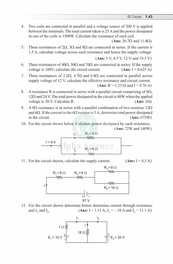
10. For the circuit shown below. Calculate power dissipated by each resistance. (Ans: 72W and 140W)
R =41 I1
I2R =82
I = 9 A
11. For the circuit shown, calculate the supply current. (Ans: I = 4.5 A)
R =164
R =62 R =81
I
87 V
+ –
R =83
12. For the circuit shown determine below determine current through resistance and I1 and I2. (Ans: I = 1.11 A, I1 = – 10 A and I2 = 11.1 A)
+
–
+
–
I1 I2
E = 20 V2
18
E = 10 V1
I1
1.44 Electrical Engineering
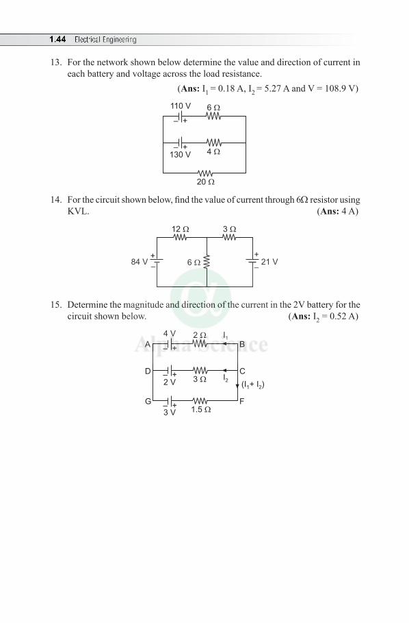
13. For the network shown below determine the value and direction of current in each battery and voltage across the load resistance.
(Ans: I1 = 0.18 A, I2 = 5.27 A and V = 108.9 V)
6
– +
– +4
20
110 V
130 V
14. For the circuit shown below, find the value of current through 6W resistor using KVL. (Ans: 4 A)
+
–
+
–
12 3
21 V84 V 6
15. Determine the magnitude and direction of the current in the 2V battery for the circuit shown below. (Ans: I2 = 0.52 A)
2
– +
– +
– +
3
1.5
4 V
2 V
3 V
I1
I2
B
C
F
(I + I )1 2
A
D
G
2.1 CONCEPT OF ELECTROMAGNETISM
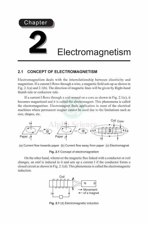
Electromagnetism deals with the interrelationship between electricity and magnetism. If a current I flows through a wire, a magnetic field sets up as shown in Fig. 2.1(a) and 2.1(b). The direction of magnetic lines will be given by Right-hand thumb rule or corkscrew rule.
If a current I flows through a coil wound on a core as shown in Fig. 2.1(c), it becomes magnetized and it is called the electromagnet. This phenomena is called the electromagnetism. Electromagnet finds application in most of the electrical machines where permanent magnet cannot be used due to the limitations such as size, shapes, etc.
N S
Coil Core
IPaper I
I
Paper I
I
(a) Current flow towards paper (b) Current flow away from paper (c) Electromagnet
Fig. 2.1 Concept of electromagnetism
On the other hand, whenever the magnetic flux linked with a conductor or coil changes, an emf is induced in it and sets up a current I if the conductor forms a closed circuit as shown in Fig. 2.1(d). This phenomena is called the electromagnetic induction.
Coil
I
N S
Movementof a magnet
Fig. 2.1 (d) Electromagnetic induction
Electromagnetism2Chapter
2.2 Electrical Engineering
2.2 IMPORTANT TERMS
1. Magnetic Field: The magnetic field is defined as the space or region around a magnet in which the magnetic effects can be detected. The magnets may be permanent magnets or electromagnets.
2. Magnetic Flux: The entire magnetic lines of force in a magnetic field are called magnetic flux (f).
In SI system of units, a unit North pole is supposed to radiate out a flux of 1 weber (Wb).The weber is that magnetic flux which, linking a circuit of 1 turn, induces in it an emf of 1 volt when the flux is reduced to zero at a uniform rate in 1 second.
3. Permeability: Permeability is a certain property of a medium, which is defined as the ability of a material to conduct magnetic flux through it. It is denoted by m.Every medium possess (i) Absolute permeability (m0) and(ii) Relative permeability (mr )
In order to measure relative permeability, vacuum or free space is considered as a reference medium, which has an Absolute Permeability given by
m0 = 4 p × 10–7 henry/m Relative Permeability: The ratio of flux density produced in a material (magnetic core) to the flux density produced in vacuum (or non-magnetic core) by the same magnetic field strength is termed as the Relative Permeability (mr). It is given by
m r = 0
permeability of materialpermeability of free space
m=m
or m = m0 mr
(Note: For vacuum or free space, mr = 1)4. Magnetic Flux Density: Magnetic flux density is defined as the total flux
passing through an area at right angles to the lines of force. It is given by
B = 2weber/m or tesla (T)Af
where f = Flux in weber and A = Area in m2
5. Magnetizing Force (H): Magnetizing force or magnetic field strength or magnetic field intensity at any point is defined as the force experienced by a unit North pole placed at that point.
Mathematically, H = NIl
ampere-turns/metre
Relationship between B, m and H: B = m H
Electromagnetism 2.3
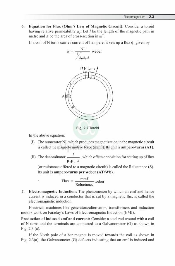
6. Equation for Flux (Ohm’s Law of Magnetic Circuit): Consider a toroid having relative permeability mr. Let l be the length of the magnetic path in metre and A be the area of cross-section in m2.If a coil of N turns carries current of I ampere, it sets up a flux f, given by
f=
0
NI1m mr A
weber
A
l
N turnsI
Fig. 2.2 Toroid
In the above equation: (i) The numerator NI, which produces magnetization in the magnetic circuit
is called the magneto motive force (mmf ). Its unit is ampere-turns (AT).
(ii) The denominator 0m mr
lA
, which offers opposition for setting up of flux
(or resistance offered to a magnetic circuit) is called the Reluctance (S). Its unit is ampere-turns per weber (AT/Wb).
\ Flux = mmf weberReluctance
7. Electromagnetic Induction: The phenomenon by which an emf and hence current is induced in a conductor that is cut by a magnetic flux is called the electromagnetic induction. Electrical machines like generators/alternators, transformers and induction
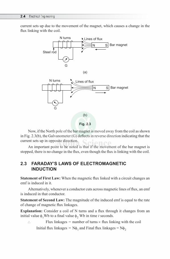
motors work on Faraday’s Laws of Electromagnetic Induction (EMI).Production of induced emf and current: Consider a steel rod wound with a coil of N turns and the terminals are connected to a Galvanometer (G) as shown in Fig. 2.3 (a).
If the North pole of a bar magnet is moved towards the coil as shown in Fig. 2.3(a), the Galvanometer (G) deflects indicating that an emf is induced and
2.4 Electrical Engineering
current sets up due to the movement of the magnet, which causes a change in the flux linking with the coil.
N turns
Steel rod
N S
Lines of flux
Bar magnet
G
(a)
N turns
N S
Lines of flux
Bar magnet
G
(b)
Fig. 2.3
Now, if the North pole of the bar magnet is moved away from the coil as shown in Fig. 2.3(b), the Galvanometer (G) deflects in reverse direction indicating that the current sets up in opposite direction.
An important point to be noted is that if the movement of the bar magnet is stopped, there is no change in the flux, even though the flux is linking with the coil.
2.3 FARADAY’S LAWS OF ELECTROMAGNETIC INDUCTION
Statement of First Law: When the magnetic flux linked with a circuit changes an emf is induced in it.
Alternatively, whenever a conductor cuts across magnetic lines of flux, an emf is induced in that conductor.Statement of Second Law: The magnitude of the induced emf is equal to the rate of change of magnetic flux linkages.Explanation: Consider a coil of N turns and a flux through it changes from an initial value f1Wb to a final value f2 Wb in time t seconds.
\ Flux linkages = number of turns × flux linking with the coil Initial flux linkages = Nf1 and Final flux linkages = Nf2
Electromagnetism 2.5
\ Induced emf, e = 2 1N Nf - ft
Wb/second
= 2 1N( ) voltf - ft
In differential form,
e = dN voltdtf
-
The direction of induced emf and current is given by Fleming’s Right-Hand Rule.(Note: The negative sign given to the right hand side of the expression is to signify the fact that the induced emf sets up a current in such a way that the magnetic effect produced by it opposes the very cause of producing it.)
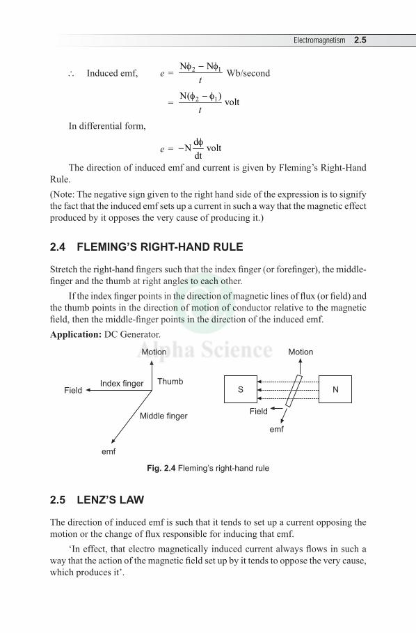
2.4 FLEMING’S RIGHT-HAND RULE
Stretch the right-hand fingers such that the index finger (or forefinger), the middle-finger and the thumb at right angles to each other.
If the index finger points in the direction of magnetic lines of flux (or field) and the thumb points in the direction of motion of conductor relative to the magnetic field, then the middle-finger points in the direction of the induced emf.Application: DC Generator.
Motion
emf
Field
NS
Motion
Middle finger
emf
ThumbIndex fingerField
Fig. 2.4 Fleming’s right-hand rule
2.5 LENZ’S LAW
The direction of induced emf is such that it tends to set up a current opposing the motion or the change of flux responsible for inducing that emf.
‘In effect, that electro magnetically induced current always flows in such a way that the action of the magnetic field set up by it tends to oppose the very cause, which produces it’.
2.6 Electrical Engineering
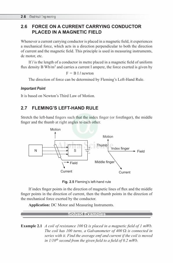
2.6 FORCE ON A CURRENT CARRYING CONDUCTOR PLACED IN A MAGNETIC FIELD
Whenever a current carrying conductor is placed in a magnetic field, it experiences a mechanical force, which acts in a direction perpendicular to both the direction of current and the magnetic field. This principle is used in measuring instruments, dc motor, etc.
If l is the length of a conductor in metre placed in a magnetic field of uniform flux density B Wb/m2 and carries a current I ampere, the force exerted is given by
F = B I l newton The direction of force can be determined by Fleming’s Left-Hand Rule.
Important Point
It is based on Newton’s Third Law of Motion.
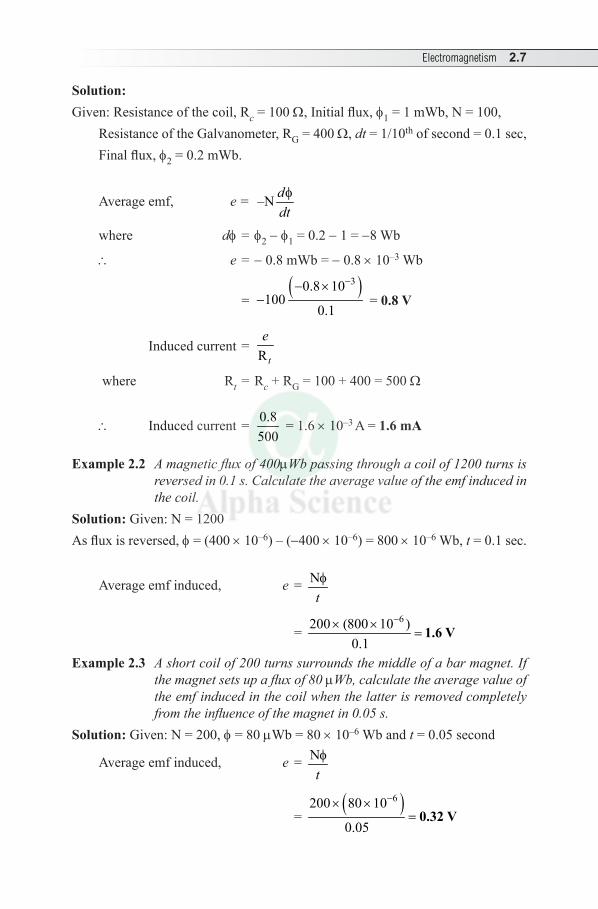
2.7 FLEMING’S LEFT-HAND RULE
Stretch the left-hand fingers such that the index finger (or forefinger), the middle finger and the thumb at right angles to each other.
Motion
Current
Field
SN+
–
Thumb
Motion
Middle finger
Current
Index fingerField
Fig. 2.5 Fleming’s left-hand rule
If index finger points in the direction of magnetic lines of flux and the middle finger points in the direction of current, then the thumb points in the direction of the mechanical force exerted by the conductor.
Application: DC Motor and Measuring Instruments.
Solved Examples
Example 2.1 A coil of resistance 100 W is placed in a magnetic field of 1 mWb. The coil has 100 turns, a Galvanometer of 400 W is connected in series with it. Find the average emf and current if the coil is moved in 1/10th second from the given field to a field of 0.2 mWb.
Electromagnetism 2.7
Solution:Given: Resistance of the coil, Rc = 100 W, Initial flux, f1 = 1 mWb, N = 100,
Resistance of the Galvanometer, RG = 400 W, dt = 1/10th of second = 0.1 sec,Final flux, f2 = 0.2 mWb.
Average emf, e = –N fddt
where df = f2 - f1 = 0.2 - 1 = -8 Wb
\ e = -0.8 mWb = -0.8 × 10⁻³ Wb
= ( )30.8 10
1000.1
-- ×- = 0.8 V
Induced current = R t
e
where Rt = Rc + RG = 100 + 400 = 500 W
\ Induced current = 0.8500
= 1.6 ×10⁻³ A = 1.6 mA
Example 2.2 A magnetic flux of 400mWb passing through a coil of 1200 turns is reversed in 0.1 s. Calculate the average value of the emf induced in the coil.
Solution: Given: N = 1200As flux is reversed, f = (400 × 10–6) – (-400 ×10–6) = 800 × 10–6 Wb, t = 0.1 sec.
Average emf induced, e = Ntf
= 6200 (800 10 )
0.1
-× ×= 1.6 V
Example 2.3 A short coil of 200 turns surrounds the middle of a bar magnet. If the magnet sets up a flux of 80 mWb, calculate the average value of the emf induced in the coil when the latter is removed completely from the influence of the magnet in 0.05 s.
Solution: Given: N = 200, f = 80 mWb = 80 ×10–6 Wb and t = 0.05 second
Average emf induced, e = Ntf
= ( )6200 80 10
0.05
-× ×= 0.32 V
2.8 Electrical Engineering
2.8 DYNAMICALLY INDUCED EMF
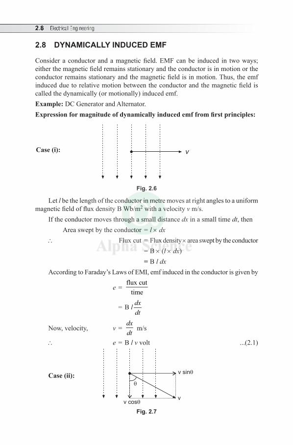
Consider a conductor and a magnetic field. EMF can be induced in two ways; either the magnetic field remains stationary and the conductor is in motion or the conductor remains stationary and the magnetic field is in motion. Thus, the emf induced due to relative motion between the conductor and the magnetic field is called the dynamically (or motionally) induced emf.Example: DC Generator and Alternator.Expression for magnitude of dynamically induced emf from first principles:
Case (i): v
Fig. 2.6
Let l be the length of the conductor in metre moves at right angles to a uniform magnetic field of flux density B Wb/m2 with a velocity v m/s.
If the conductor moves through a small distance dx in a small time dt, then Area swept by the conductor = l × dx \ Flux cut = Flux density × area swept by the conductor = B × (l × dx) = B l dxAccording to Faraday’s Laws of EMI, emf induced in the conductor is given by
e = flux cut
time
= B l dxdt
Now, velocity, v = dxdt
m/s
\ e = B l v volt ...(2.1)
Case (ii):
v
v sin
v cos
Fig. 2.7
Electromagnetism 2.9
Let the same conductor moves at an angle q (with respect to the direction of magnetic field) in the same uniform magnetic field with same velocity.
The velocity v can be resolved into components;(i) Component v cosq: It is parallel to the magnetic field and hence does not
induce any emf.(ii) Component v sinq: It is perpendicular to the magnetic field and hence induces
an emf. Therefore, the emf equation (2.1) can be rewritten as e = B l v sinq volt ...(2.2)
Solved Examples
Example 2.4 A conductor of active length 30 cm carries a current of 100 A and lies at right-angles to a magnetic field of density 0.4 T. Calculate the force in newton exerted on it. If the force causes the conductor to move at a velocity of 10 m/s. Calculate (a) the emf induced in it and (b) the power developed by it in watt.
Solution: Given: l = 30 cm = 30 × 10–2 m, I = 100 A, B = 0.4 T and v = 10 m/s.Force acting on the conductor, F = B I l (Note: This is motor action) = 0.4 × 100 × (30 × 10–2) = 12 N
(a) The emf induced, e = B l v (Note: This is generator action) = 0.4 × (30 × 10–2) × 10 = 1.2 V
(b) Power developed, P = e × I = 1.2 ×100 = 120 W
Example 2.5 A straight conductor has an active length of 20 cm and moves in uniform magnetic field of 0.5 T at the rate of 5 m. Find the generated emf, if the motion of the conductor is (a) parallel, (b) perpendicular and (c) at an angle of 30° to the direction of the field.
Solution: Given: (Active) length, l = 20 cm = 20 × 10–2 m,B = 0.5 T (i.e. Wb/m2), rate of movement of conductor, v = 5 mAccording to equation.(2.2), dynamically induced emf, e = B l v sin q
(a) If the motion of the conductor is parallel, emf will not be induced.Substituting the data given and q = 0 in the above equation, e = 0.5 × 0.2 × 5 sin (0) = 0
(b) If the motion of the conductor is perpendicular, maximum emf will be induced Substituting the data given and q = 900 in the above equation, e = 0.5 × 0.2 × 5 sin(90°) = 0.5 V
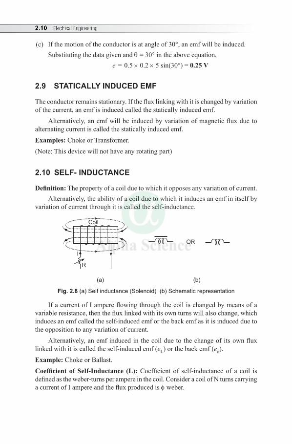
2.10 Electrical Engineering
(c) If the motion of the conductor is at angle of 30°, an emf will be induced.Substituting the data given and q = 30° in the above equation, e = 0.5 × 0.2 × 5 sin(30°) = 0.25 V
2.9 STATICALLY INDUCED EMF
The conductor remains stationary. If the flux linking with it is changed by variation of the current, an emf is induced called the statically induced emf.
Alternatively, an emf will be induced by variation of magnetic flux due to alternating current is called the statically induced emf.Examples: Choke or Transformer.(Note: This device will not have any rotating part)
2.10 SELF- INDUCTANCE
Definition: The property of a coil due to which it opposes any variation of current.Alternatively, the ability of a coil due to which it induces an emf in itself by
variation of current through it is called the self-inductance.
Coil
OR
I
R
(a) (b)
Fig. 2.8 (a) Self inductance (Solenoid) (b) Schematic representation
If a current of I ampere flowing through the coil is changed by means of a variable resistance, then the flux linked with its own turns will also change, which induces an emf called the self-induced emf or the back emf as it is induced due to the opposition to any variation of current.
Alternatively, an emf induced in the coil due to the change of its own flux linked with it is called the self-induced emf (eL) or the back emf (eb).Example: Choke or Ballast. Coefficient of Self-Inductance (L): Coefficient of self-inductance of a coil is defined as the weber-turns per ampere in the coil. Consider a coil of N turns carrying a current of I ampere and the flux produced is f weber.
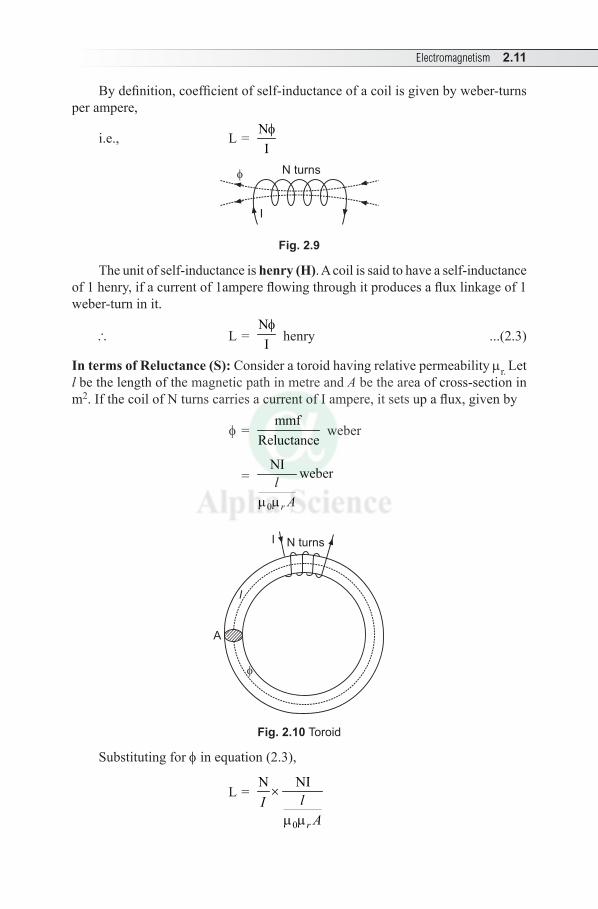
Electromagnetism 2.11
By definition, coefficient of self-inductance of a coil is given by weber-turns per ampere,
i.e., L = NIf
N turns
I
Fig. 2.9
The unit of self-inductance is henry (H). A coil is said to have a self-inductance of 1 henry, if a current of 1ampere flowing through it produces a flux linkage of 1 weber-turn in it.
\ L = NIf
henry ...(2.3)
In terms of Reluctance (S): Consider a toroid having relative permeability mr. Let l be the length of the magnetic path in metre and A be the area of cross-section in m2. If the coil of N turns carries a current of I ampere, it sets up a flux, given by
f =
mmfReluctance
weber
=
0
NI weber
m mr
lA
A
l
N turnsI
Fig. 2.10 Toroid
Substituting for f in equation (2.3),
L =
0
N NI×
m mr
lIA
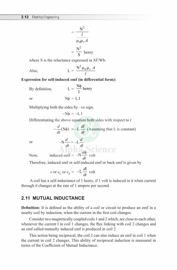
2.12 Electrical Engineering
= 2
0
N
m mr
lA
= 2N
S henry
where S is the reluctance expressed in AT/Wb.
Also, L = 2
0 N
m mr Al
Expression for self-induced emf (in differential form):
By definition, L = N henryIf
or Nf = L I
Multiplying both the sides by –ve sign, -Nf = -L IDifferentiating the above equation both sides with respect to t
(N ) –Ld dIdt dt
- f = (Assuming that L is constant)
or –N = –Ld ddt dt
Now, induced emf = –N ddtf
volt
Therefore, induced emf or self-induced emf or back emf is given by
e or e L or eb = IL d
dt- volt
A coil has a self-inductance of 1 henry, if 1 volt is induced in it when current through it changes at the rate of 1 ampere per second.
2.11 MUTUAL INDUCTANCE
Definition: It is defined as the ability of a coil or circuit to produce an emf in a nearby coil by induction, when the current in the first coil changes.
Consider two magnetically coupled coils 1 and 2 which, are close to each other, whenever the current I in coil 1 changes, the flux linking with coil 2 changes and an emf called mutually induced emf is produced in coil 2.
This action being reciprocal; the coil 2 can also induce an emf in coil 1 when the current in coil 2 changes. This ability of reciprocal induction is measured in terms of the Coefficient of Mutual Inductance.
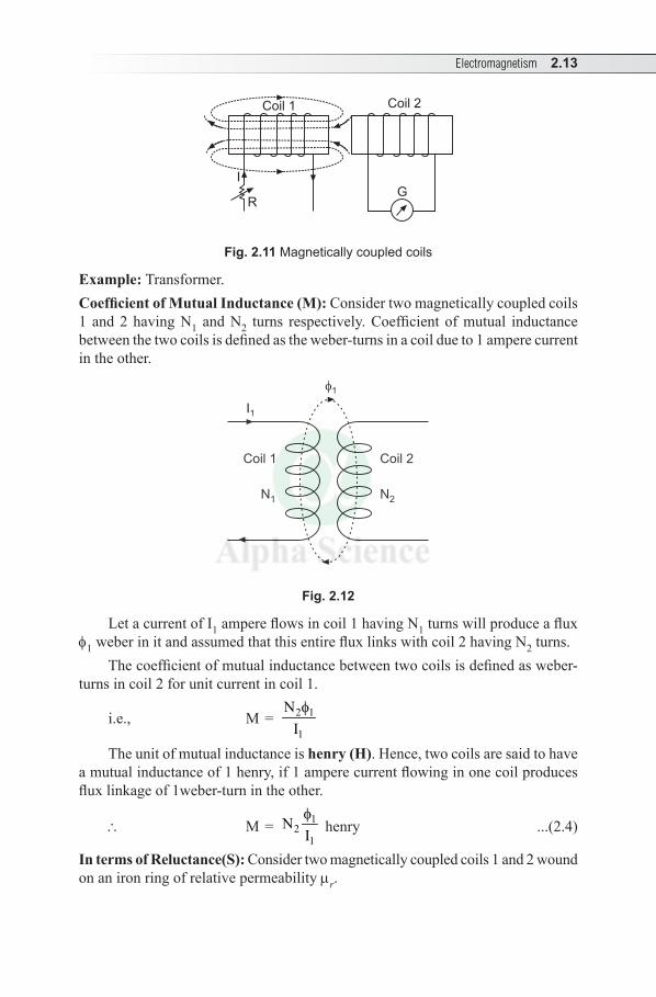
Electromagnetism 2.13
Coil 1
I
R
Coil 2
G
Fig. 2.11 Magnetically coupled coils
Example: Transformer. Coefficient of Mutual Inductance (M): Consider two magnetically coupled coils 1 and 2 having N1 and N2 turns respectively. Coefficient of mutual inductance between the two coils is defined as the weber-turns in a coil due to 1 ampere current in the other.
I1
1
Coil 1
N1
Coil 2
N2
Fig. 2.12
Let a current of I1 ampere flows in coil 1 having N1 turns will produce a flux f1 weber in it and assumed that this entire flux links with coil 2 having N2 turns.
The coefficient of mutual inductance between two coils is defined as weber-turns in coil 2 for unit current in coil 1.
i.e., M = 2 1
1
NIf
The unit of mutual inductance is henry (H). Hence, two coils are said to have a mutual inductance of 1 henry, if 1 ampere current flowing in one coil produces flux linkage of 1weber-turn in the other.
\ M = 12
1N
If
henry ...(2.4)
In terms of Reluctance(S): Consider two magnetically coupled coils 1 and 2 wound on an iron ring of relative permeability mr.
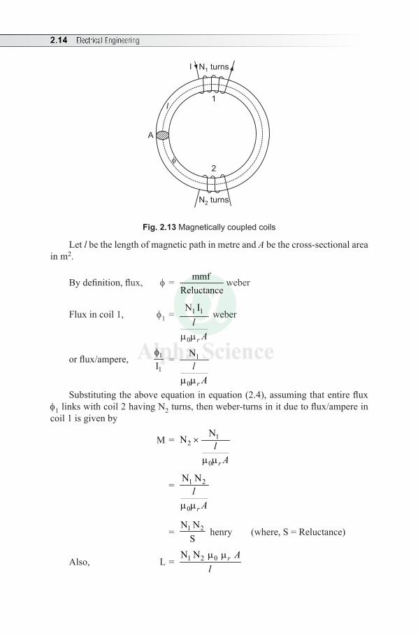
2.14 Electrical Engineering
A
l
N turns1I
2
1
N turns2
Fig. 2.13 Magnetically coupled coils
Let l be the length of magnetic path in metre and A be the cross-sectional area in m2.
By definition, flux, f = mmfReluctance
weber
Flux in coil 1, f 1 = 1 1
0
N I
m mr
lA
weber
or flux/ampere, 1
1If
= 1
0
N
m mr
lA
Substituting the above equation in equation (2.4), assuming that entire flux f1 links with coil 2 having N2 turns, then weber-turns in it due to flux/ampere in coil 1 is given by
M = 12
0
N N ×
m mr
lA
= 1 2
0
N N
m mr
lA
= 1 2N NS
henry (where, S = Reluctance)
Also, L = 1 2 0 N N m mr Al
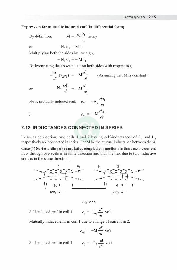
Electromagnetism 2.15
Expression for mutually induced emf (in differential form):
By definition, M = 12
1IN f
henry
or N2 f1 = M I1
Multiplying both the sides by –ve sign, - N2 f1 = - M I1
Differentiating the above equation both sides with respect to t,
2 1(N )ddt
- f = 1I–M ddt
(Assuming that M is constant)
or 12N d
dtf
- = 1I–M ddt
Now, mutually induced emf, eM = 12
dNtdf
-
\ eM = 1I– M ddt
2.12 INDUCTANCES CONNECTED IN SERIES
In series connection, two coils 1 and 2 having self-inductances of L1 and L2 respectively are connected in series. Let M be the mutual inductance between them.Case (1) Series aiding or cumulative coupled connection: In this case the current flow through two coils is in same direction and thus the flux due to two inductive coils is in the same direction.
I
1
I
2
e1
em1
e2
em2
Fig. 2.14
Self-induced emf in coil 1, e1 = – 1 IL ddt
volt
Mutually induced emf in coil 1 due to change of current in 2,
em1 = I–M ddt
volt
Self-induced emf in coil 1, e2 = – 2 IL
ddt
volt
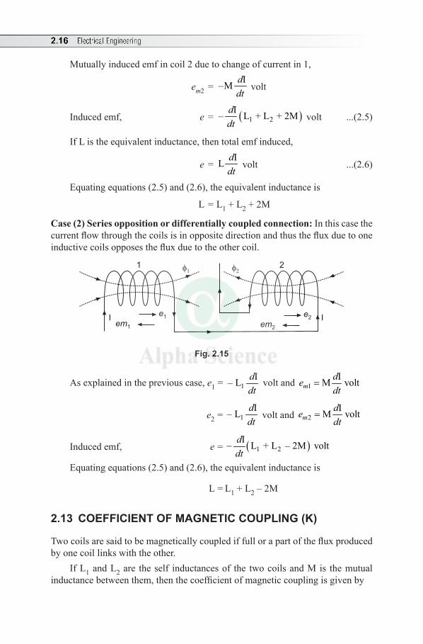
2.16 Electrical Engineering
Mutually induced emf in coil 2 due to change of current in 1,
em2 = I–M ddt
volt
Induced emf, e = ( )1 2 I– L + L + 2Mddt
volt ...(2.5)
If L is the equivalent inductance, then total emf induced,
e = IL ddt
volt ...(2.6)
Equating equations (2.5) and (2.6), the equivalent inductance is
L = L1 + L2 + 2M
Case (2) Series opposition or differentially coupled connection: In this case the current flow through the coils is in opposite direction and thus the flux due to one inductive coils opposes the flux due to the other coil.
1
I
2
e2
em2
e1
em1
I
Fig. 2.15
As explained in the previous case, e1 = 1 I– L ddt
volt and 1IM voltm
dedt
=
e2 = 1 I– L ddt
volt and 2IM voltm
dedt
=
Induced emf, e = ( )1 2 I L + L – 2M voltddt
-
Equating equations (2.5) and (2.6), the equivalent inductance is
L = L1 + L2 – 2M
2.13 COEFFICIENT OF MAGNETIC COUPLING (K)
Two coils are said to be magnetically coupled if full or a part of the flux produced by one coil links with the other.
If L1 and L2 are the self inductances of the two coils and M is the mutual inductance between them, then the coefficient of magnetic coupling is given by
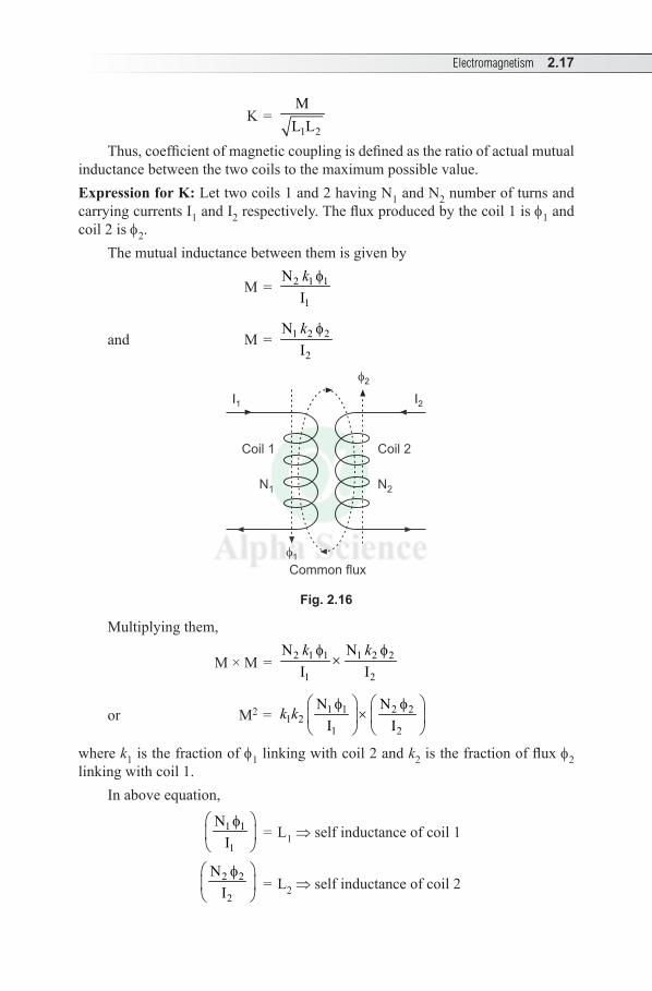
Electromagnetism 2.17
K = 1 2
ML L
Thus, coefficient of magnetic coupling is defined as the ratio of actual mutual inductance between the two coils to the maximum possible value.Expression for K: Let two coils 1 and 2 having N1 and N2 number of turns and carrying currents I1 and I2 respectively. The flux produced by the coil 1 is f1 and coil 2 is f2.
The mutual inductance between them is given by
M = 2 1 1
1
NIk f
and M = 1 2 2
2
NIk f
I1
2
Coil 1
N1
Coil 2
N2
1
I2
Common flux
Fig. 2.16
Multiplying them,
M × M = 2 1 1 1 2 2
1 2
N NI Ik kf f
×
or M2 = 1 1 2 21 2
1 2
N NI I
k k f f
×
where k1 is the fraction of f1 linking with coil 2 and k2 is the fraction of flux f2 linking with coil 1.
In above equation,
1 1
1
NI
f
= L1 ⇒ self inductance of coil 1
2 2
2
NI
f
= L2 ⇒ self inductance of coil 2
2.18 Electrical Engineering
\ M2 = k 1 k2 L1 L2
or M = 1 2 1 2L Lk k
If the entire flux produced by one coil links with other, k1 = k2 = K. Then, maximum mutual inductance existing between them is given by
M = K 1 2L L
or K = 1 2
ML L
Important Points
l If the entire flux produced by one coil links with other, then k1 = k2 = K = 1(unity) and maximum mutual inductance between the coils is
M = 1 2L L .l If K = 1(maximum), the coils are said to be tightly coupled and if K is a fraction,
the coils are said to be loosely coupled. l If there is no common flux between the two coils they are said to be magnetically
isolated, i.e., M = 0 and K = 0.
2.14 ENERGY STORED IN A MAGNETIC FIELD
Let i be the instantaneous value of current in t seconds and L be the coefficient of self-inductance. Then induced emf at that instant is given by
e = L voltdidt
...(2.7)
\Instantaneous power, p = e iSubstituting for e from equation (2.7),
p = L di idt
= L diidt
...(2.8)
Then work done in time dt to overcome this opposition is given by dw = p.dtSubstituting for p from equation (2.8),
dw = L dii dtdt
= Li diTherefore, the total work done W in establishing the maximum steady current
I is given by
Electromagnetism 2.19
0
wdw∫ =
I
0
L i di∫
or W = 21 L I2
If L is in henry and I in ampere, then energy stored in magnetic field is given by
W = 21 L I2
joule
Solved Examples
Example 2.6 Calculate the inductance and energy stored in the magnetic field of a air-cored solenoid 100 cm long 5 cm in diameter and wound with 1000 turns, if the current rises from 0 to 10 A.
Solution: Given: l = 100 cm = 100 × 10–2 m, diameter d = 5 cm = 5 × 10⁻² m, N = 1000, I = 10 A and mr = 1 for air-cored solenoid.
Self-inductance, L = 2
0N r Alm m ...(2.9)
where m0 = Absolute permeability = 4 p × 10–7 H/m
Cross-sectional area, A = 2 –2 2(5 10 )
4 4dp p× ×
= = 1.963 × 10⁻³ m2
Substituting the values for m0, A and the given data in equation (2.9),
L = –7 –3 2
2(4 10 ) 1 (1.963 10 ) (1000)
100 10-p × × × × ×
×
= 2.467 × 10⁻³ H = 2.467 mH
Energy stored in magnetic field, W = 21 L I2
= –3 21 (2.467 10 ) (10)2× × × = 0.123 J
Example 2.7 A coil of 1500 turns, gives rise to a magnetic flux of 2.5 mWb, when carrying a certain current. If the current is reversed in 0.2 seconds, what is the average value of the emf induced in the coil?
Solution: Given: N = 1500, f = 2.5 m Wb = 2.5 ×10⁻³ Wb.As current is reversed in 0.2 second, dt = 0.2.
Average emf induced, e = N ddtf (ignoring negative sign)
Reversal of current causes the reversal of flux,
2.20 Electrical Engineering
i.e., change in flux, df = (2.5 × 10⁻³) - (-2.5 × 10⁻³) = 5 × 10⁻³ Wb
\ e = 35 101500
0.2
- ×=
37.5 V
Example 2.8 A coil of 300 turns wound on a core of non-magnetic material has an inductance of 10 mH. Calculate (a) The flux produced by a current of 5 A and (b) The average value of the emf induced when a current of 5 A is reversed in 8 m second.
Solution: Given: N = 300, L = 10 mH = 10 × 10–3 H, I = 5 Aand t = 8 ms = 8 × 10⁻³ second
Flux produced, f = L I
N×
Nbecause, LIf =
= 3(10 10 ) 5
300
-× × = 0.167 × 10⁻³ Wb = 0.167 mWb
Average emf induced, e = IL d
dtAs the current changes from 5 A to – 5 A, d I = 5 – (-5) = 10
Then, average rate of change of current = –3I 10 1250 A/s
8 10= =
×ddt
\ e = 0.01 × 1250 = 12.5 V
Example 2.9 A flux of 0.5 mWb is produced in a coil of 900 turns wound on a wooden ring due to a current of 3 A. Calculate (a) the inductance of the coil, (b) the average emf induced in the coil when a current of 5 A is switched off, assuming that the current to fall to zero in 1 ms and (c) the mutual inductance between the coils, if a second coil of 600 turns was uniformly wound over the first coil.
Solution: Given: f = 0.5 mWb = 0.5 × 10⁻³ Wb, N1 = 900 and N2 = 600, I = 3 A,Initial current, I1 = 5 A and Final current, I2 = 0, t = 1 ms = 1 × 10⁻³ s Also, when second coil is wound over the first coil, then flux remains the same
(a) Inductance of the coil, L = 1NIf
= ( )3900 0.5 10
3
-× × = 0.15 H
(b) Average induced emf, e = L × average rate of change of current
The average rate of change of current = 2 13
I I 0 – 51 10-
- = × t = - 5000 A/s
\ Average induced emf, e = (0.15 ×-5000) = -750 V
Electromagnetism 2.21
(c) Mutual inductance between the coils, M = N2 If
= ( )30.5 10
6003
-×× = 0.1 H
Example 2.10 If an emf of 5 volt is induced in a coil when the current in an adjacent coil varies at a rate of 80 A/s, what is the value of the mutual inductance of the two coils?
Solution: Given: e = 5 volt and didt
= 80 A/m
Average emf induced, e = M didt
or mutual inductance, M = 5
80edidt
= = 0.0625 H = 62.5 mH
Example 2.11 A non-magnetic ring having a mean diameter of 30 cm and cross-sectional area of 4 cm2 is uniformly wound with two coils A and B one over the other. A has 90 turns and B has 240 turns. Calculate the mutual inductance between the coils. Also, calculate the emf induced in B when a current of 6 A is reversed in 0.02 seconds.
Solution: Given: Mean diameter D = 30 cm = 30 × 10–2 m, A = 4 cm2 = 4 × 10⁻⁴ m2
NA = 90 × NB = 240, Length of Iron path, l = p D = p × (30 × 10–2) = 0.942 mFor non-magnetic material, mr = 1, dI = 6 A, dt = 0.02Also, if windings are wound one over the other, the flux remains constant.
Mutual-inductance, M = A B 0N N m mr Al
= ( ) ( )7 490 240 4 10 1 4 10
0.942
- -× × p× × × ×
= 1.15 × 10⁻⁵ H
Mutually induced emf, eM = IM d
dt
= (1.15 × 10⁻⁵) ( )6 6
0.02- - = 6.9 × 10⁻³ V
Example 2.12 Two coils having 50 and 500 turns are wound side by side on a closed Iron circuit of cross-section 50 cm2 and mean length 120 cm. Estimate the self-inductance of each coil, mutual inductance between them if the relative permeability of Iron is 1000. If the current in one coil grows steadily from zero to 5 A in 0.01 s, find the induced emf in the other.
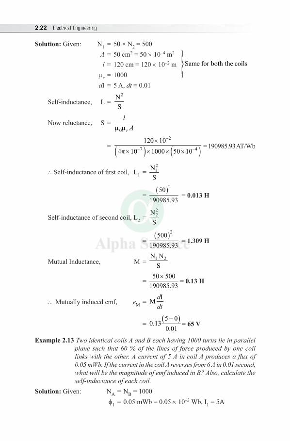
2.22 Electrical Engineering
Solution: Given: N1 = 50 × N2 = 500 A = 50 cm2 = 50 × 10–4 m2
l = 120 cm = 120 × 10–2 m Same for both the coils mr = 1000
dI = 5 A, dt = 0.01
Self-inductance, L = 2N
S
Now reluctance, S = 0m mr
lA
= ( ) ( )2
7 4120 10
4 10 1000 50 10
-
- -
×
p × × × × = 190985.93 AT/Wb
\Self-inductance of first coil, L1 = 21N
S
= ( )250
190985.93 = 0.013 H
Self-inductance of second coil, L2 = 22N
S
= ( )2500
190985.93 = 1.309 H
Mutual Inductance, M = 1 2N NS
= 50 500
190985.93×
= 0.13 H
\Mutually induced emf, eM = IM d
dt
= ( )5 0
0.130.01-
= 65 V
Example 2.13 Two identical coils A and B each having 1000 turns lie in parallel plane such that 60 % of the lines of force produced by one coil links with the other. A current of 5 A in coil A produces a flux of 0.05 mWb. If the current in the coil A reverses from 6 A in 0.01 second, what will be the magnitude of emf induced in B? Also, calculate the self-inductance of each coil.
Solution: Given: NA = NB = 1000 f1 = 0.05 mWb = 0.05 × 10⁻³ Wb, I1 = 5A
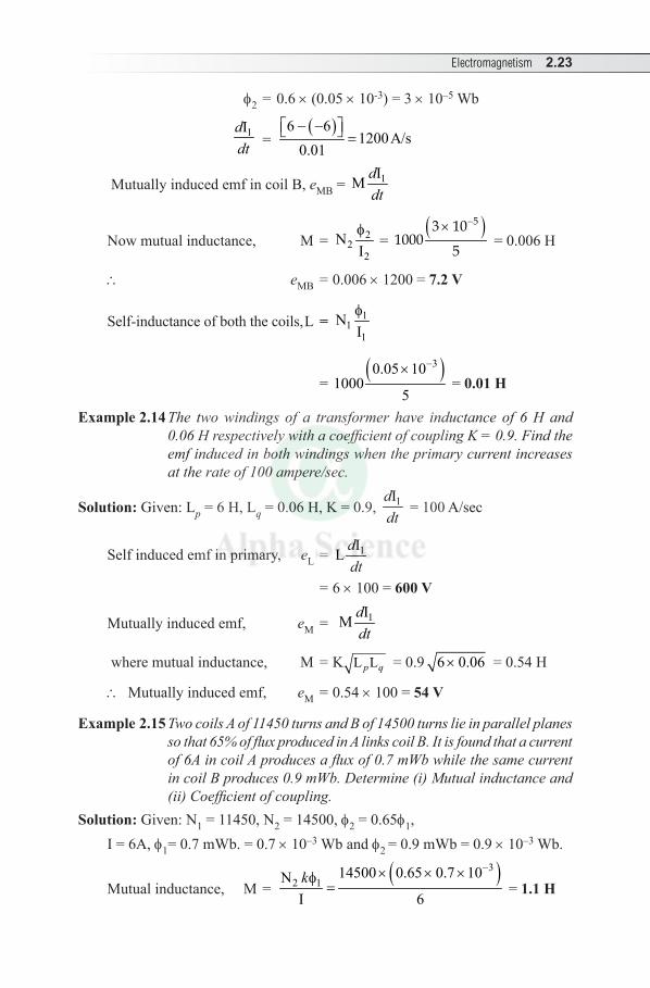
Electromagnetism 2.23
f2 = 0.6 × (0.05 × 10-3) = 3 × 10⁻⁵ Wb
1Iddt =
( )6 61200A/s
0.01- - =
Mutually induced emf in coil B, eMB = 1IM ddt
Now mutual inductance, M = 22
2N
If
= ( )53 10
10005
-× = 0.006 H
\ eMB = 0.006 × 1200 = 7.2 V
Self-inductance of both the coils, L = 11
1N
If
= ( )30.05 10
10005
-× = 0.01 H
Example 2.14 The two windings of a transformer have inductance of 6 H and 0.06 H respectively with a coefficient of coupling K = 0.9. Find the emf induced in both windings when the primary current increases at the rate of 100 ampere/sec.
Solution: Given: Lp = 6 H, Lq = 0.06 H, K = 0.9, 1Iddt
= 100 A/sec
Self induced emf in primary, eL = 1IL ddt
= 6×100 = 600 V
Mutually induced emf, eM = 1IM ddt
where mutual inductance, M = K L Lp q = 0.9 6 0.06× = 0.54 H
\ Mutually induced emf, eM = 0.54 × 100 = 54 V
Example 2.15 Two coils A of 11450 turns and B of 14500 turns lie in parallel planes so that 65% of flux produced in A links coil B. It is found that a current of 6A in coil A produces a flux of 0.7 mWb while the same current in coil B produces 0.9 mWb. Determine (i) Mutual inductance and (ii) Coefficient of coupling.
Solution: Given: N1 = 11450, N2 = 14500, f2 = 0.65f1, I = 6A, f1= 0.7 mWb. = 0.7 × 10⁻³ Wb and f2 = 0.9 mWb = 0.9 × 10⁻³ Wb.
Mutual inductance, M = ( )3
2 114500 0.65 0.7 10N
I 6k
-× × ×f= = 1.1 H
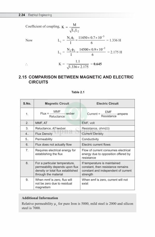
2.24 Electrical Engineering
Coefficient of coupling, 1 2
MKL L
=
Now L1 = 3
1 1N 11450 0.7 10I 6
−φ × ×= = 1.336 H
L1 = 3
2 2N 14500 0.9 10I 6
−φ × ×= = 2.175 H
∴ K = 1.1
1.336 2.175× = 0.645
2.15 COMPARISON BETWEEN MAGNETIC AND ELECTRIC CIRCUITS
Table 2.1
S.No. Magnetic Circuit Electric Circuit
1.MMF Flux = weber
Reluctance EMFCurrent = ampere
Resistance
2. MMF, AT EMF, volt
3. Reluctance, AT/weber Resistance, ohm(W)
4.. Flux Density Current Density
5.. Permeability Conductivity
6. Flux does not actually flow Electric current flows
7. Requires electrical energy for establishing the flux
Flow of current consumes electrical energy due to opposition offered by resistance
8. For a particular temperature, permeability depends upon flux density or total flux established through the material
If temperature is maintained constant, then resistance remains constant and independent of current strength
9. When mmf is zero, flux will not be zero due to residual magnetism
When emf is zero, current will not exist
Additional InformationRelative permeability mr for pure Iron is 5000, mild steel is 2000 and silicon steel is 7000.

Electromagnetism 2.25
Multiple Choice Questions
Choose the Correct Answer
1. Magnetic flux can be obtained by(a) current carrying conductor (b) permanent magnet(c) both (a) and (b) (d) none of these
2. AT/m is the unit of (a) mmf (b) reluctance(c) magnetizing force (d) magnetic flux density
3. The unit of magnetic flux is (a) weber (b) weber/second (c) weber/m (d) weber/m2
4. Magnetic flux sets up more easily in (a) air (b) wood (c) iron (d) vacuum
5. Magnetic flux is the ratio of mmf to (a) current (b) inductance (c) resistance (d) reluctance
6. The unit of flux density is(a) Newton/metre (b) weber (c) weber/m2 (d) Tesla/m2
7. The unit of inductance is(a) Weber (b) Farad (c) Weber/m2 (d) Henry
8. The unit of MMF is(a) weber-turns (b) weber/m (c) ampere/m (d) ampere-turns
9. If a current carrying conductor is placed in a magnetic field it experiences-force(a) mechanical (b) electrical (c) chemical (d) both (a) and (b)
10. The unit of reluctance is(a) AT/Wb (b) Wb/AT (c) weber-turns (d) AT
11. The emf induced in a coil of N turns is(a) N(df/dt) (b) N(df/di) (c) –N(df/dt) (d) L(df/dt)
12. Direction of induced emf and current is given by(a) Fleming’s Right-Hand Rule (b) Fleming’s Left-Hand Rule (c) both (a) and (b) (d) none of the above
13. Fleming’s Right-Hand Rule is applicable for (a) transformer (b) motor (c) generator (d) none of these
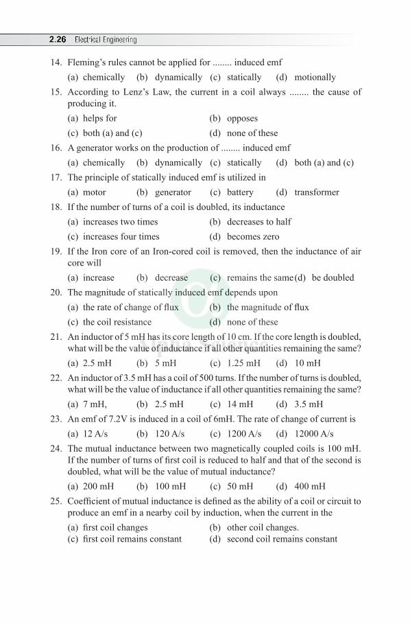
2.26 Electrical Engineering
14. Fleming’s rules cannot be applied for ........ induced emf(a) chemically (b) dynamically (c) statically (d) motionally
15. According to Lenz’s Law, the current in a coil always ........ the cause of producing it.(a) helps for (b) opposes(c) both (a) and (c) (d) none of these
16. A generator works on the production of ........ induced emf(a) chemically (b) dynamically (c) statically (d) both (a) and (c)
17. The principle of statically induced emf is utilized in(a) motor (b) generator (c) battery (d) transformer
18. If the number of turns of a coil is doubled, its inductance (a) increases two times (b) decreases to half (c) increases four times (d) becomes zero
19. If the Iron core of an Iron-cored coil is removed, then the inductance of air core will (a) increase (b) decrease (c) remains the same (d) be doubled
20. The magnitude of statically induced emf depends upon (a) the rate of change of flux (b) the magnitude of flux(c) the coil resistance (d) none of these
21. An inductor of 5 mH has its core length of 10 cm. If the core length is doubled, what will be the value of inductance if all other quantities remaining the same?(a) 2.5 mH (b) 5 mH (c) 1.25 mH (d) 10 mH
22. An inductor of 3.5 mH has a coil of 500 turns. If the number of turns is doubled, what will be the value of inductance if all other quantities remaining the same?(a) 7 mH, (b) 2.5 mH (c) 14 mH (d) 3.5 mH
23. An emf of 7.2V is induced in a coil of 6mH. The rate of change of current is(a) 12 A/s (b) 120 A/s (c) 1200 A/s (d) 12000 A/s
24. The mutual inductance between two magnetically coupled coils is 100 mH. If the number of turns of first coil is reduced to half and that of the second is doubled, what will be the value of mutual inductance?(a) 200 mH (b) 100 mH (c) 50 mH (d) 400 mH
25. Coefficient of mutual inductance is defined as the ability of a coil or circuit to produce an emf in a nearby coil by induction, when the current in the (a) first coil changes (b) other coil changes.(c) first coil remains constant (d) second coil remains constant
Electromagnetism 2.27
26. If coefficient of magnetic coupling < 1, then the coils are said to be(a) tightly coupled (b) loosely coupled(c) no common flux (d) not magnetically coupled
27. The ideal coefficient of coupling is (a) zero (b) one (c) 0.75 (d) 0.5
28. When all the flux due to current in one coil links with other coil, the mutual inductance between coils is given by
(a) M = 1 2L L (b) M = K 1 2L L (c) M = L1L2 (d) M = L1L2/2
29. The flux linkage between the coils is maximum, when m =
(a) 1/ 1 2L L (b) 1 2L L (c) L1 = L2 (d) L1/L2
30. The maximum value of co-efficient of coupling is(a) 100% (b) more than 100%(c) 90% (d) none of these
Answers:—1. (c) 2. (c) 3. (a) 4. (c) 5. (d) 6. (c) 7. (d) 8. (d) 9. (a) 10. (a)
11. (c) 12. (a) 13. (c) 14. (c) 15. (b) 16. (b) 17. (d) 18. (c) 19. (b) 20. (a)
21. (a) 22. (c) 23. (c) 24. (b) 25. (a) 26. (b) 27. (b) 28. (a) 29. (b) 30. (a)
Review Questions
1. Define the following terms: (i) Permeability and (ii) Magnetic flux density.2. Explain the electromagnetic induction?3. State and explain Faraday’s Laws of Electromagnetic Induction.4. Distinguish between statically induced emf and dynamically induced emf.
Give examples.5. Derive the expression for the magnitude of dynamically induced emf.6. State (i)Fleming’s Right-Hand Rule (ii)Fleming’s Left-Hand Rule and
(iii) Lenz’s Law. Mention the applications for (i) and (ii).7. Explain Fleming’s Right-Hand Rule and Fleming’s Left-Hand Rule as applied
to electrical machines.8. Define (i) Self-inductance and (ii) Mutual inductance. Mention their unit and
write the formulae to calculate each of them.9. Derive the expressions for calculating the self-inductance and mutual
inductance.
2.28 Electrical Engineering
10. Derive the expressions for self-induced emf and mutually induced emf 11. Derive an expression for the energy stored in an inductor of self inductance L
henry carrying a current of I ampere.12. What do you mean by coefficient of magnetic coupling?13. Define coefficient of coupling and find its relation with L1, L2 and M.14. With usual notations derive an expression for coefficient of magnetic coupling. 15. Bring out the comparison between magnetic circuit and electric circuit.
Exercises
1. The current in a coil decreases from 10 A to 4 A in 0.1 second. If the inductance of the coil is 4H, what is the emf induced in the coil? (Ans: 240 V)
2. A flux of 0.4 mWb is created by a current of 10 A flowing through a coil of 100 turns. If the current reverses in 0.01 second, what is the inductance of the coil? (Ans: 4 mH)
3. An air cored coil of length 2.5 cm has an average cross-sectional area of 2 cm2. How many number of turns are required to give an inductance of 400mH? (Ans: 200)
4. A current-carrying conductor is situated at right angles to a uniform magnetic field having a density of 0.3 T. Calculate the force, (in newton /m length)on the conductor when the current is 200 A. (Ans: 60 N/m)
5. A conductor of 150 mm long is carrying a current of 60 A at right angles to a magnetic field. The force on the conductor is 3 N. Calculate the density of the field. (Ans: 50 A )
6. Calculate the inductance of a circuit in which 30 V are induced when the current varies at the rate of 200 A/s. (Ans: 0.15 H)
7. A certain coil is wound with 50 turns and a current of 8 A produces a flux of 200 mWb. Calculate (a) the inductance of the coil corresponding to a reversal of the current, (b) the average emf induced when the current is reversed in 0.2 second. (Ans: 1.25 mWb, 0.1 V)
8. A large electromagnet is wound with 1000 turns. A current of 2 A in this winding produces a flux through the coil of 0.03 Wb. Calculate the inductance of the electromagnet. If the current in the coil is reduced from 2 A to zero in 0.1 second, what average emf will be induced in the coil ? Assume that there is no residual flux. (Ans: 15 H, 300 V)
9. A coil consists of 750 turns and a current of 10 A in the coil gives rise to a magnetic flux of 1200 mWb. Calculate the inductance of the coil, and determine the average emf induced in the coil when this current is reversed in 0.01 second. (Ans: 0.09 H, 180 V)
Electromagnetism 2.29
10. If two coils have a mutual inductance of 400 mH, calculate the emf induced in one coil when the current in the other coil varies at a rate of 30000 A/m. (Ans: 12 V)
11. A coil with 250 turns carries a current of 2A and produces flux of 0.3 mWb. When this current is reduced to zero in 2 millisecond, the voltage induced in a nearby coil is 60 V. calculate (i) Self-inductance of each coil, (ii) Mutual inductance between the coils. Assume coefficient of coupling as 0.7.
(Ans: L1 = 0.037 H, M = 0.06 H, L2 = 0) 12. If the current through a coil having an inductance of 0.5 H is reduced from
5A to 2A in 0.05 second, calculate the mean value of the emf induced in the coil. (Ans: -30 V)
13. A coil of 1500 turns carrying a current of 5 A produces a flux of 2.5 mWb. If the current is reversed in 0.2 second (or in 1/20th of a second), find the average value of emf induced in the coil. Also, find the self-inductance of the coil.
(Ans: L = 0.75 H and e = 37.5 V) 14. Two magnetically coupled coils have a co-efficient of coupling 0.8. the current
in coil P is 3A and total flux 0.4 mWb. The voltage induced in coil Q is 85V when current in coil is reduced to zero in 3 msec. The number of turns of coil P is 300. Determine L1, M, L2 and number of turns of coil Q.
(Ans: L1 = 40 mH, M = 0.085 H, L2 = 282 mH and NB = 80)15. The winding of an electromagnet is wound with 96 turns and has a resistance
of 50 W. The exciting voltage is 250V and flux linking the coil is 5 mWb. Find the energy stored in the magnetic field. Then, if the current is reversed in 0.1 second, what emf is induced in the coil? (Ans: W = 1.2 J and e = –9.6 V)
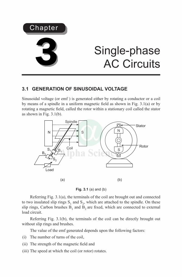
3.1 GENERATION OF SINUSOIDAL VOLTAGE
Sinusoidal voltage (or emf ) is generated either by rotating a conductor or a coil by means of a spindle in a uniform magnetic field as shown in Fig. 3.1(a) or by rotating a magnetic field, called the rotor within a stationary coil called the stator as shown in Fig. 3.1(b).
Stator
RotorS
O
O
NN S
Spindle
Coil
Load
S2
B1B2
S1
(a) (b)
Fig. 3.1 (a) and (b)
Referring Fig. 3.1(a), the terminals of the coil are brought out and connected to two insulated slip rings S1 and S2, which are attached to the spindle. On these slip rings, Carbon brushes B1 and B2 are fixed, which are connected to external load circuit.
Referring Fig. 3.1(b), the terminals of the coil can be directly brought out without slip rings and brushes.
The value of the emf generated depends upon the following factors:(i) The number of turns of the coil,(ii) The strength of the magnetic field and(iii) The speed at which the coil (or rotor) rotates.
Single-phase AC Circuits3
Chapter
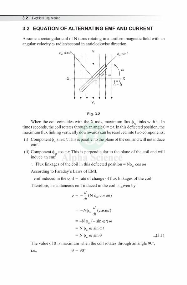
3.2 Electrical Engineering
3.2 EQUATION OF ALTERNATING EMF AND CURRENT
Assume a rectangular coil of N turns rotating in a uniform magnetic field with an angular velocity w radian/second in anticlockwise direction.
t = 0XX1
= t
O = 0
m
cos Y
Y1
m
sin
Fig. 3.2
When the coil coincides with the X-axis, maximum flux fm links with it. In time t seconds, the coil rotates through an angle q = wt. In this deflected position, the maximum flux linking vertically downwards can be resolved into two components; (i) Component fm sin wt: This is parallel to the plane of the coil and will not induce
emf. (ii) Component fm cos wt: This is perpendicular to the plane of the coil and will
induce an emf.\ Flux linkages of the coil in this deflected position = Nfm cos wtAccording to Faraday’s Laws of EMI, emf induced in the coil = rate of change of flux linkages of the coil.Therefore, instantaneous emf induced in the coil is given by
e = −ddt
tm( cos )N φ ω
= −Nddt
tmφ ω(cos )
= –N fm (– sin wt) w = N fm w sin wt = N fm w sin q ...(3.1)
The value of q is maximum when the coil rotates through an angle 90°, i.e., q = 90°
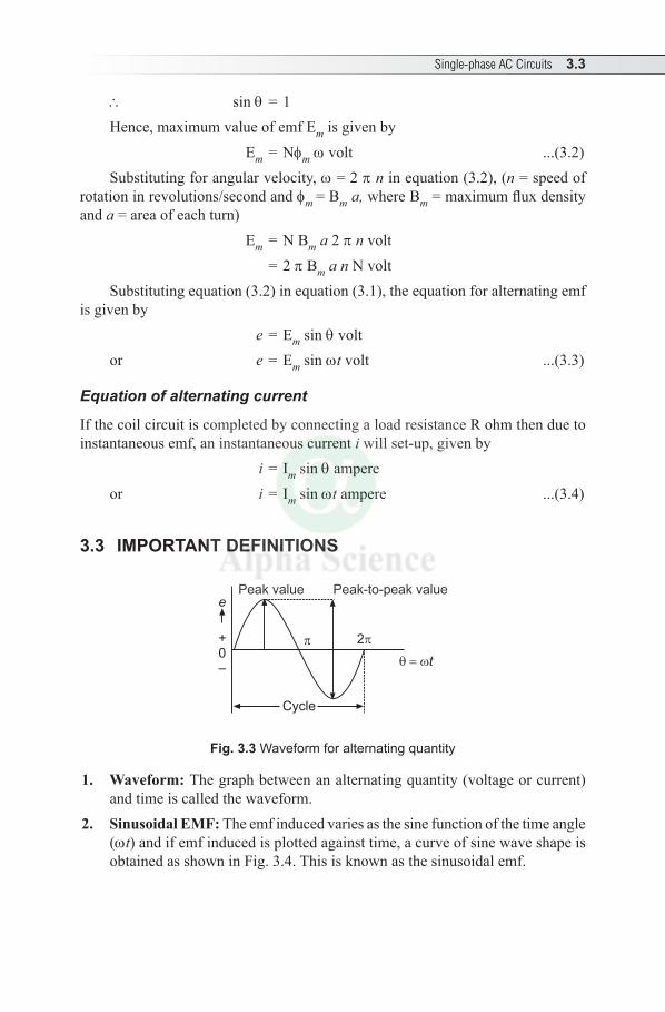
Single-phase AC Circuits 3.3
\ sin q = 1Hence, maximum value of emf Em is given by Em = Nfm w volt ...(3.2)Substituting for angular velocity, w = 2 p n in equation (3.2), (n = speed of
rotation in revolutions/second and fm = Bm a, where Bm = maximum flux density and a = area of each turn)
Em = N Bm a 2 p n volt = 2 p Bm a n N volt Substituting equation (3.2) in equation (3.1), the equation for alternating emf
is given by e = Em sin q voltor e = Em sin wt volt ...(3.3)
Equation of alternating current
If the coil circuit is completed by connecting a load resistance R ohm then due to instantaneous emf, an instantaneous current i will set-up, given by
i = Im sin q ampereor i = Im sin wt ampere ...(3.4)
3.3 IMPORTANT DEFINITIONS
t
2
e
+0–
Peak value Peak-to-peak value
Cycle
Fig. 3.3 Waveform for alternating quantity
1. Waveform: The graph between an alternating quantity (voltage or current) and time is called the waveform.
2. Sinusoidal EMF: The emf induced varies as the sine function of the time angle (wt) and if emf induced is plotted against time, a curve of sine wave shape is obtained as shown in Fig. 3.4. This is known as the sinusoidal emf.
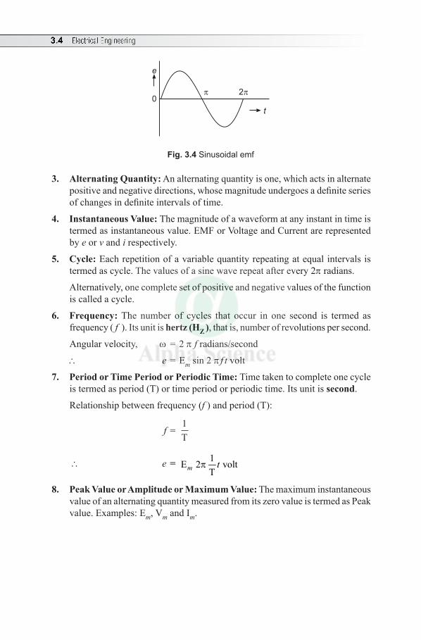
3.4 Electrical Engineering
2
e
0
t
Fig. 3.4 Sinusoidal emf
3. Alternating Quantity: An alternating quantity is one, which acts in alternate positive and negative directions, whose magnitude undergoes a definite series of changes in definite intervals of time.
4. Instantaneous Value: The magnitude of a waveform at any instant in time is termed as instantaneous value. EMF or Voltage and Current are represented by e or v and i respectively.
5. Cycle: Each repetition of a variable quantity repeating at equal intervals is termed as cycle. The values of a sine wave repeat after every 2p radians.
Alternatively, one complete set of positive and negative values of the function is called a cycle.
6. Frequency: The number of cycles that occur in one second is termed as frequency ( f ). Its unit is hertz (HZ ), that is, number of revolutions per second.
Angular velocity, w = 2 p f radians/second
\ e = Em sin 2 p f t volt
7. Period or Time Period or Periodic Time: Time taken to complete one cycle is termed as period (T) or time period or periodic time. Its unit is second.
Relationship between frequency (f ) and period (T):
f = 1T
\ e = 1E 2 voltT
pm t
8. Peak Value or Amplitude or Maximum Value: The maximum instantaneous value of an alternating quantity measured from its zero value is termed as Peak value. Examples: Em, Vm and Im.
Single-phase AC Circuits 3.5
Solved Examples
Example 3.1 A coil of 100 turns is rotated at 1500 r/min in a magnetic field having a uniform density of 0.05 T, the axis of rotation being at right angles to the direction of the flux. The mean area per turn is 40 cm2. Calculate (a) the frequency, (b) the period, (c) the maximum value of the generated emf and (d) the value of the generated emf. When the coil has rotated through 30° from the position of zero emf.
Solution: Given: N = 100, n = 1500 r/min or rpm (i.e. revolutions per minute),B = 0.05 T, Mean Area A = 40 cm2 = 40 × 10–4 m2, q = 30°
(a) When the coil rotates through one revolution, the emf generated in the coil undergoes one cycle of variation. By definition, frequency = number of cycles per second or f = number of revolutions per second
= 1500
60 = 25 Hz
(b) By definition, period is the time taken to complete one cycle
i.e., T = 1f
because 1T
f =
= 125
= 0.04 second
(c) Maximum emf generated, Em = 2 p B A n N
= 2 p × 0.05 × (40 × 10–4) × 150060
× 100
= 3.14 V(d) The value of the generated emf when the coil has rotated through an angle 30°
from the position of zero emf is given by e = Em sin qGiven that q = 30°
Then, sin q = sin 30° = 0.5 e = 3.14 × 0.5 = 1.57 V
3.4 CONCEPT OF AVERAGE VALUE AND RMS VALUE
Figure 3.5 (a) shows a current waveform. Assuming n number of mid-ordinates i1, i2, i3 .... in in first half-cycle and applying graphical or mid-ordinate method,
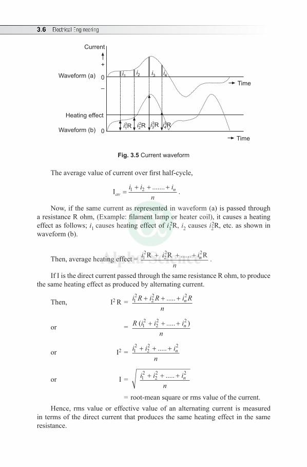
3.6 Electrical Engineering
Time
Time
Waveform (a) 0
–
+
Current
Heating effect
Waveform (b) 0
i3 i4i2i1
i3 i4i2i12R2R2R2R
Fig. 3.5 Current waveform
The average value of current over first half-cycle,
Iav ni i in
=+ + +1 2 ....... .
Now, if the same current as represented in waveform (a) is passed through a resistance R ohm, (Example: filament lamp or heater coil), it causes a heating effect as follows; i1 causes heating effect of i1
2R, i2 causes i22R, etc. as shown in
waveform (b).
Then, average heating effect = i i in
n12
22 2R R R+ + +...... .
If I is the direct current passed through the same resistance R ohm, to produce the same heating effect as produced by alternating current.
Then, I2 R = i R i R i Rn
n12
22 2+ + +.....
or = R i i in
n( ..... )12
22 2+ + +
or I2 = i i in
n12
22 2+ + +.....
or I = i i in
n12
22 2+ + +.....
= root-mean square or rms value of the current.Hence, rms value or effective value of an alternating current is measured
in terms of the direct current that produces the same heating effect in the same resistance.
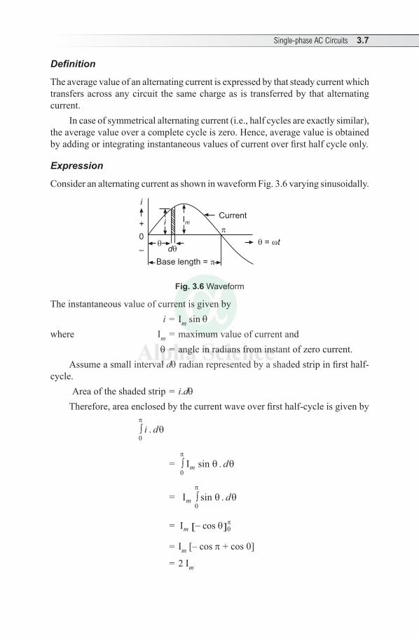
Single-phase AC Circuits 3.7
Definition
The average value of an alternating current is expressed by that steady current which transfers across any circuit the same charge as is transferred by that alternating current.
In case of symmetrical alternating current (i.e., half cycles are exactly similar), the average value over a complete cycle is zero. Hence, average value is obtained by adding or integrating instantaneous values of current over first half cycle only.
Expression
Consider an alternating current as shown in waveform Fig. 3.6 varying sinusoidally.
Current
= t
Base length =
d
Imi
i
+
0
–
Fig. 3.6 Waveform
The instantaneous value of current is given by i = Im sin qwhere Im = maximum value of current and
q = angle in radians from instant of zero current.
Assume a small interval dq radian represented by a shaded strip in first half-cycle.
Area of the shaded strip = i.dq Therefore, area enclosed by the current wave over first half-cycle is given by
∫0
π
θi d.
= ∫0
π
θ θIm dsin .
= Im d∫0
π
θ θsin .
= Im −[ ]cos θ θπ
= Im [– cos p + cos 0]
= 2 Im
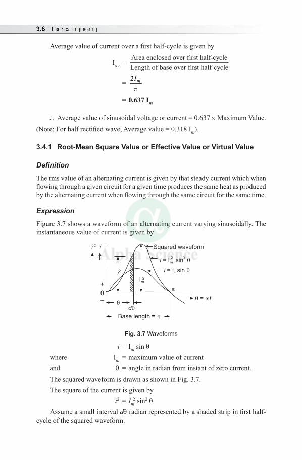
3.8 Electrical Engineering
Average value of current over a first half-cycle is given by
Iav = Area enclosed over first half-cycleLength of base over firsst half-cycle
= 2 mIp
= 0.637 Im
\ Average value of sinusoidal voltage or current = 0.637 × Maximum Value.(Note: For half rectified wave, Average value = 0.318 Im).
3.4.1 Root-Mean Square Value or Effective Value or Virtual Value
Definition
The rms value of an alternating current is given by that steady current which when flowing through a given circuit for a given time produces the same heat as produced by the alternating current when flowing through the same circuit for the same time.
Expression
Figure 3.7 shows a waveform of an alternating current varying sinusoidally. The instantaneous value of current is given by
= t
Base length =
i = I sinm
i = I sinm
2 2
Squared waveformi 2 i
d
i2
Im
2
+
0–
Fig. 3.7 Waveforms
i = Im sin q where Im = maximum value of current and q = angle in radian from instant of zero current.The squared waveform is drawn as shown in Fig. 3.7. The square of the current is given by i2 = Im
2 sin2 q
Assume a small interval dq radian represented by a shaded strip in first half-cycle of the squared waveform.
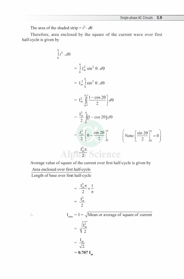
Single-phase AC Circuits 3.9
The area of the shaded strip = i2 . dq Therefore, area enclosed by the square of the current wave over first
half-cycle is given by
∫0
2π
θi d.
=
∫0
2 2π
θ θI dm sin .
= Im d2
0
2∫π
θ θsin .
= Im d2
0
1 22
−
∫
cos θθ
π
= Im d2
021 2−[ ]∫ cos θ θ
π
= Im2
022
2θ
θ π
−
sin Note: sin 22
00
θ π
=
= 2 I2mp
Average value of square of the current over first half-cycle is given by Area enclosed over first half-cycleLength of base over firsst half-cycle
= Im
2
21ππ
×
= Im2
2
\ Irms = I = Mean or average of square of current
= Im
2
2
= Im
2 = 0.707 Im
3.10 Electrical Engineering
\ RMS value of sinusoidal voltage or current = 0.707 × Maximum value(Note: For half rectified wave, RMS value = 0.5 Im)
(The above method of approach is Analytical Method or Integral Method).
Importance of rms value
1. The measuring instruments like ammeter and voltmeter reads the rms value of alternating current and alternating voltage.
2. In electrical engineering works, unless indicated, the given values of voltage and current are taken as the rms values.
3.5 FORM FACTOR OF A SINE WAVE
K f = RMS value
Average value
= 0.707 × Maximum value0.637 × Maximum value
= 1.11
3.6 PEAK OR CREST OR AMPLITUDE FACTOR
Kp or Kc or Ka = Maximum volue
RMS value.
= Maximum volue
0.707 × Maximum value=1.414
Solved Examples
Example 3.2 An alternating current of sinusoidal waveform has rms value of 10 A. What are the peak values of this current over one cycle?
Solution: Given: Current, I = 10 ABy definition, I = 0. 707 Im
or Im = I0.707
=10
0 707. = 14.14 A
\ The peak values are 14.14 A and –14.14 A
Example 3.3 An alternating voltage has the equation v = 141.4 sin (377t) volt; what are the values of (a) rms voltage, (b) frequency and (c) the instantaneous voltage when t = 3 ms?
Solution: Given: v = 141.4 sin (377 t) voltThis equation is of the form v = Vm sin wt
Single-phase AC Circuits 3.11
where w = angular velocity = 2pf radians/second
(a) By definition, rms value of voltage is given by V = Vm 0.707 As per given data, Vm = 141.4 \ V = 141.4 × 0.707 = 99.969 ≈ 100 V(b) Angular velocity, w = 2pf
or frequency, f = ωπ π2=
3772
= 60 Hz
(c) Instantaneous voltage, v = Vm sin wt Given that t = 3 ms = 3 × 10⁻³ second \ v = 141.4 sin (377 × 3 × 10–3) = 2.791 V
Example 3.4 If the waveform of a voltage has a form factor of 1.15 and peak factor of 1.5, if the peak value is 4.5kV, calculate the average and rms values of the voltage.
Solution: Given: Kf = 1.15, Kp = 1.5, Vm = 4.5 kV = 4500 V
Peak factor, Kp = Maximum value
RMS valueVV
= m
or RMS value of voltage, V = VK
4500m
p=
1.5 = 3000 V
Form factor, Kf = RMS volueAverage value
VV
=av
or average value of voltage, Vav = V
K f=
30001 15.
= 2608.69 V
Example 3.5 The equation for an alternating voltage is given by v = 0.04 sin(2000 t + 60°) volt. Calculate the frequency and instantaneous voltage when t = 160 µ second. What is the time represented by a 60° phase angle?
Solution: Given: v = 0.04 sin (2000 t + 60°) volt This equation is of the form v = Vm sin (wt + f) volt \Vm = 0.04, w = 2000 rad/sec, t = 160 µsecond = 160 × 10–6 second and f = 60°
To find frequency:Angular velocity, w = 2pf
or frequency, f = ωπ π2
20002
= = 318.3 Hz
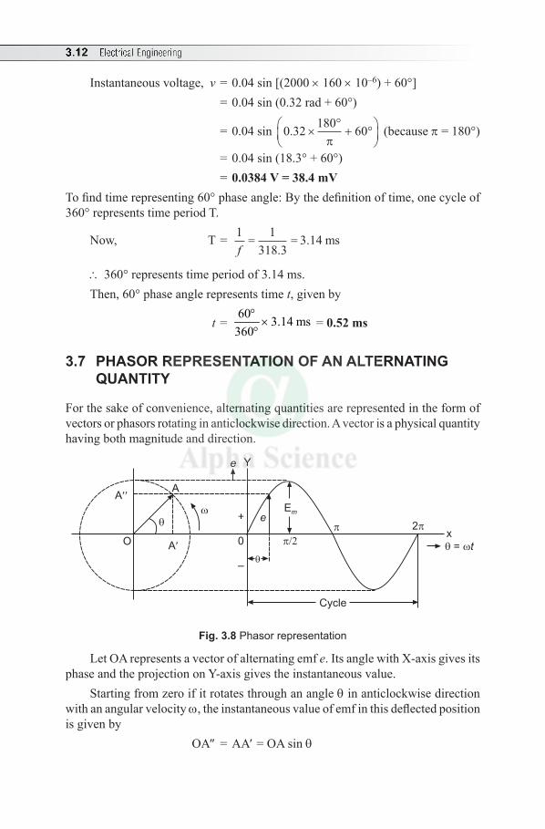
3.12 Electrical Engineering
Instantaneous voltage, v = 0.04 sin [(2000 × 160 × 10–6) + 60°] = 0.04 sin (0.32 rad + 60°)
= 0.04 sin 0 32 180 60. ×°+ °
π
(because p = 180°)
= 0.04 sin (18.3° + 60°) = 0.0384 V = 38.4 mV
To find time representing 60° phase angle: By the definition of time, one cycle of 360° represents time period T.
Now, T = 1 1318 3f
= =.
3.14 ms
\ 360° represents time period of 3.14 ms. Then, 60° phase angle represents time t, given by
t = 60 3.14 ms
360°
×°
= 0.52 ms
3.7 PHASOR REPRESENTATION OF AN ALTERNATING QUANTITY
For the sake of convenience, alternating quantities are represented in the form of vectors or phasors rotating in anticlockwise direction. A vector is a physical quantity having both magnitude and direction.
eE
m
Cycle
= t
2
A
A
A
e Y
x
+
0
–
O
Fig. 3.8 Phasor representation
Let OA represents a vector of alternating emf e. Its angle with X-axis gives its phase and the projection on Y-axis gives the instantaneous value.
Starting from zero if it rotates through an angle q in anticlockwise direction with an angular velocity w, the instantaneous value of emf in this deflected position is given by
OA″ = AA′ = OA sin q

Single-phase AC Circuits 3.13
or e = Em sin q where Em = maximum value of emf (at q = 90°) and thus represents its
magnitude. Therefore, as the vector OA rotates through one revolution or 2p radians, one
cycle of emf waveform will be obtained.
3.7.1 Phase
An alternating quantity changes in magnitude and direction at every instant. Thus, the condition of an alternating quantity at any particular instant is called the phase.
Phase of an alternating quantity at any particular instant is defined as the fractional part of a period or cycle through which the quantity has advanced from a selected origin.
3.7.2 Phase Difference
If two alternating quantities, say, e and i are considered simultaneously with same frequency, they may not pass through a particular point at the same time and thus these two quantities have phase difference.
The phase difference is measured by the angular difference between points, wherever the two curves cross the base or reference line in the same direction.
To explain phase the difference, consider two alternating quantities emf e and current i represented by vectors OA and OB respectively as shown in Fig. 3.9.Case (i): The emf e is ahead in phase and thus it leads the current i by an angle f or current i lags behind the emf e by an angle f. Thus, the vector OA leads the vector OB by an angle f or the vector OB lags behind the vector OA by an angle f.
0
e i
t
2
i
e
O A
B
Fig. 3.9 Waveforms and phasor diagrams
[Note: If emf, e = Em sin wt and current, i = Im sin (wt - f)
Thus, emf e leads current i by an angle f or current i lags behind emf e by an angle f]. Hence, a leading alternating quantity reaches its maximum value earlier than
the other, and a lagging alternating quantity reaches its maximum value later than the other.
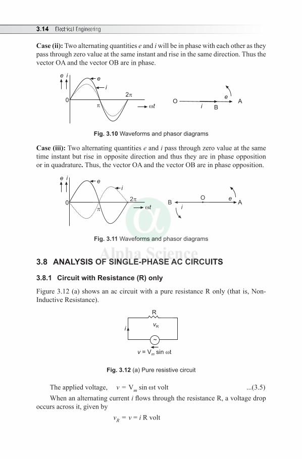
3.14 Electrical Engineering
Case (ii): Two alternating quantities e and i will be in phase with each other as they pass through zero value at the same instant and rise in the same direction. Thus the vector OA and the vector OB are in phase.
0
e i
t
2
i
e
iO A
B
e
Fig. 3.10 Waveforms and phasor diagrams
Case (iii): Two alternating quantities e and i pass through zero value at the same time instant but rise in opposite direction and thus they are in phase opposition or in quadrature. Thus, the vector OA and the vector OB are in phase opposition.
0
e i
t
2
i
e
B Ai
eO
Fig. 3.11 Waveforms and phasor diagrams
3.8 ANALYSIS OF SINGLE-PHASE AC CIRCUITS
3.8.1 Circuit with Resistance (R) only
Figure 3.12 (a) shows an ac circuit with a pure resistance R only (that is, Non-Inductive Resistance).
~
vRi
R
v = V sin tm
Fig. 3.12 (a) Pure resistive circuit
The applied voltage, v = Vm sin wt volt ...(3.5) When an alternating current i flows through the resistance R, a voltage drop
occurs across it, given by vR = v = i R volt
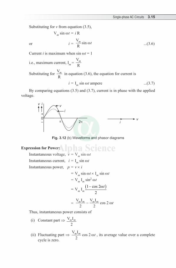
Single-phase AC Circuits 3.15
Substituting for v from equation (3.5), Vm sin wt = i R
or i = VRm tsin w ...(3.6)
Current i is maximum when sin wt = 1
i.e., maximum current, Im = VR
m
Substituting for VR
m in equation (3.6), the equation for current is
i = Im sin wt ampere ...(3.7)
By comparing equations (3.5) and (3.7), current is in phase with the applied voltage.
0
v i
i
v
iv
2
+
–
Fig. 3.12 (b) Waveforms and phasor diagrams
Expression for Power: Instantaneous voltage, v = Vm sin wtInstantaneous current, i = Im sin wtInstantaneous power, p = v × i = Vm sin wt × Im sin wt = Vm Im sin2 wt
= Vm Im( )1 cos 2
2- wt
= V I V Im m m m t
2 22− cos ω
Thus, instantaneous power consists of
(i) Constant part ⇒ V Im m
2
(ii) Fluctuating part ⇒ V Im m t
22cos w , its average value over a complete
cycle is zero.
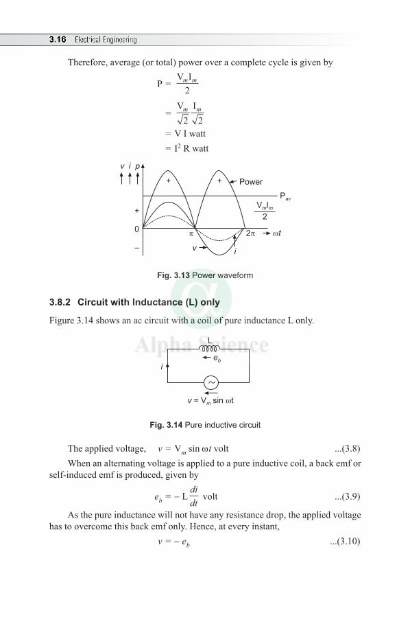
3.16 Electrical Engineering
Therefore, average (or total) power over a complete cycle is given by
P = V Im m
2
= V Im m
2 2 = V I watt = I2 R watt
Pav
VmIm
2
Power
2 t
vi
++
v i p
+
0
–
Fig. 3.13 Power waveform
3.8.2 Circuit with Inductance (L) only
Figure 3.14 shows an ac circuit with a coil of pure inductance L only.
eb
L
i
v = V sin tm
Fig. 3.14 Pure inductive circuit
The applied voltage, v = Vm sin wt volt ...(3.8) When an alternating voltage is applied to a pure inductive coil, a back emf or
self-induced emf is produced, given by
eb = - Ldidt
volt ...(3.9)
As the pure inductance will not have any resistance drop, the applied voltage has to overcome this back emf only. Hence, at every instant,
v = - eb ...(3.10)
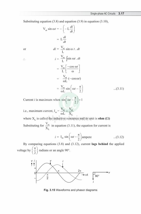
Single-phase AC Circuits 3.17
Substituting equation (3.8) and equation (3.9) in equation (3.10),
Vm sin wt = - −
L di
dt
= L didt
or di = VLm sin w t . dt
\ i = VLm t dtsin .ω∫
= VL
m t−
cos ωω
= VL
m tω
ω( cos )−
= VLm t
ωω
πsin −
2
...(3.11)
Current i is maximum when sin ωπt −
=2
1
i.e., maximum current, Im = L
V VL X
=w
m m
where XL is called the inductive reactance and its unit is ohm (Ω)
Substituting for VXL
m
in equation (3.11), the equation for current is
i = Im tsin ωπ
−
2
ampere ...(3.12)
By comparing equations (3.8) and (3.12), current lags behind the applied
voltage by π2
radians or an angle 90°.
90°t
2
–2
+
0
–
v i
i
v
iv
Fig. 3.15 Waveforms and phasor diagrams
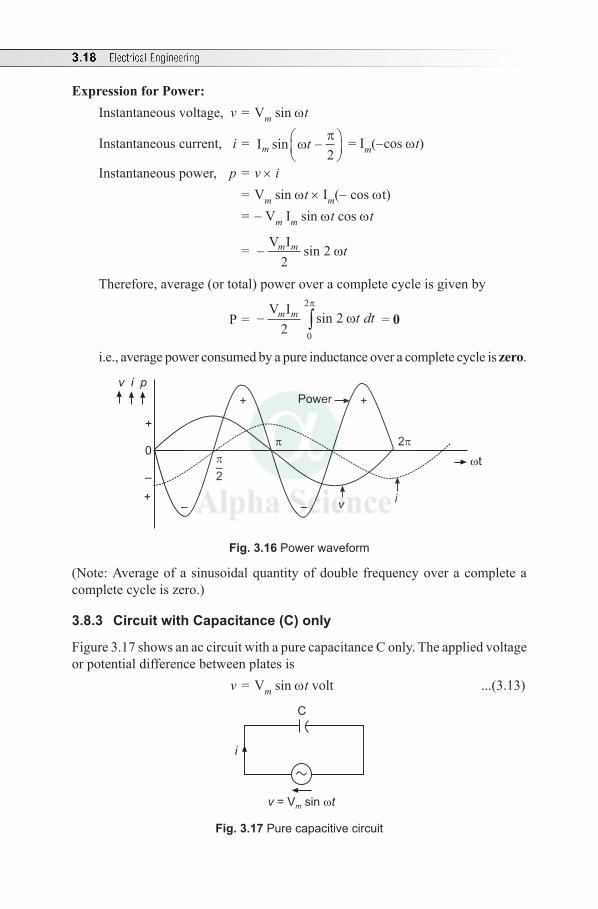
3.18 Electrical Engineering
Expression for Power: Instantaneous voltage, v = Vm sin wt
Instantaneous current, i = Im tsin ωπ
−
2
= Im(-cos wt)
Instantaneous power, p = v × i = Vm sin wt × Im(- cos wt) = - Vm Im sin wt cos wt
= − V Im m t2
2sin ω
Therefore, average (or total) power over a complete cycle is given by
P = − ∫V Im m t dt
22
0
2
sin ωπ
= 0
i.e., average power consumed by a pure inductance over a complete cycle is zero.
v i p
vi
2
–2
+
0
–
+– –
+ +Power
t
Fig. 3.16 Power waveform
(Note: Average of a sinusoidal quantity of double frequency over a complete a complete cycle is zero.)
3.8.3 Circuit with Capacitance (C) only
Figure 3.17 shows an ac circuit with a pure capacitance C only. The applied voltage or potential difference between plates is
v = Vm sin wt volt ...(3.13)
C
i
v t= V sinm
Fig. 3.17 Pure capacitive circuit
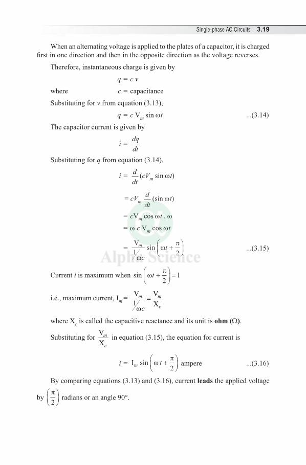
Single-phase AC Circuits 3.19
When an alternating voltage is applied to the plates of a capacitor, it is charged first in one direction and then in the opposite direction as the voltage reverses.
Therefore, instantaneous charge is given by
q = c v
where c = capacitance
Substituting for v from equation (3.13),
q = c Vm sin wt ...(3.14)
The capacitor current is given by
i = dqdt
Substituting for q from equation (3.14),
i = ddt
(cVm sin wt)
= cVm ddt
(sin wt)
= cVm cos wt . w
= w c Vm cos wt
= Vm
ct
1 2ω
ωπsin +
...(3.15)
Current i is maximum when sin ωπt +
=2
1
i.e., maximum current, Im = V V1 X
=w
m m
cc
where Xc is called the capacitive reactance and its unit is ohm (Ω).
Substituting for VX
m
c in equation (3.15), the equation for current is
i = Im tsin ωπ
+
2
ampere ...(3.16)
By comparing equations (3.13) and (3.16), current leads the applied voltage
by π2
radians or an angle 90°.
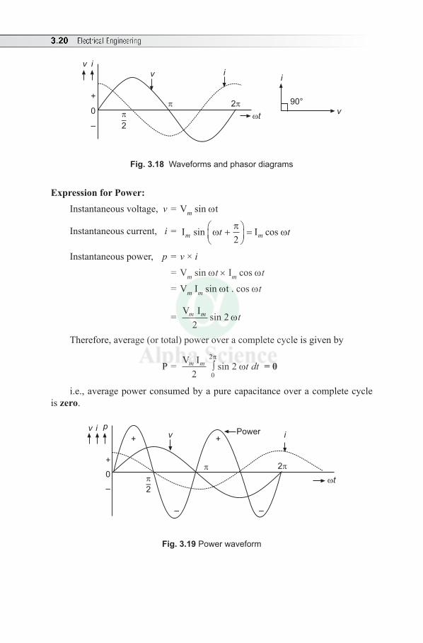
3.20 Electrical Engineering
90°v
i
2
t
v i
–2
v i
+
0
–
Fig. 3.18 Waveforms and phasor diagrams
Expression for Power:Instantaneous voltage, v = Vm sin wt
Instantaneous current, i = I Im mt tsin cosωπ
ω+
=2
Instantaneous power, p = v × i = Vm sin wt × Im cos wt = Vm Im sin wt . cos wt
= V Im m t2
2sin w
Therefore, average (or total) power over a complete cycle is given by
P = V Im m t dt2
20
2∫π
ωsin = 0
i.e., average power consumed by a pure capacitance over a complete cycle is zero.
v i p
+
0
–
v i+ +
– –
–2
2
Power
t
Fig. 3.19 Power waveform
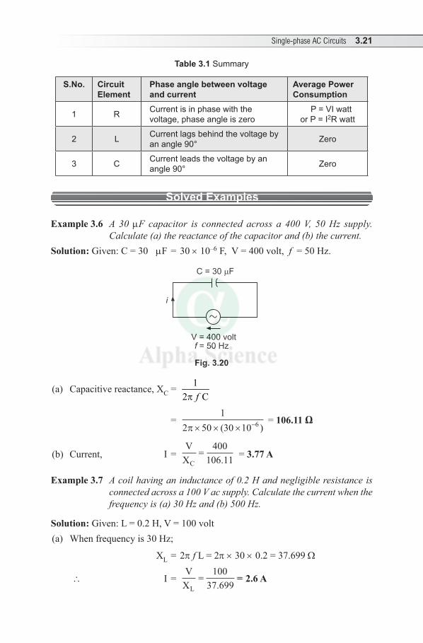
Single-phase AC Circuits 3.21
Table 3.1 Summary
S.No. Circuit Element
Phase angle between voltage and current
Average Power Consumption
1 R Current is in phase with the voltage, phase angle is zero
P = VI wattor P = I2R watt
2 L Current lags behind the voltage by an angle 90° Zero
3 C Current leads the voltage by an angle 90° Zero
Solved Examples
Example 3.6 A 30 µF capacitor is connected across a 400 V, 50 Hz supply. Calculate (a) the reactance of the capacitor and (b) the current.
Solution: Given: C = 30 µF = 30 × 10–6 F, V = 400 volt, f = 50 Hz.
C = 30 F
i
V = 400 voltf = 50 Hz
Fig. 3.20
(a) Capacitive reactance, XC = 12 Cfp
= 1
2 50 30 10 6π× × × −( ) = 106.11 Ω
(b) Current, I = V
XC=
400106 11. = 3.77 A
Example 3.7 A coil having an inductance of 0.2 H and negligible resistance is connected across a 100 V ac supply. Calculate the current when the frequency is (a) 30 Hz and (b) 500 Hz.
Solution: Given: L = 0.2 H, V = 100 volt(a) When frequency is 30 Hz;
XL = 2p f L = 2p × 30 × 0.2 = 37.699 Ω
\ I = V
XA
L= =
10037 699
2 6.
. = 2.6 A
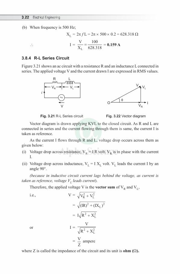
3.22 Electrical Engineering
(b) When frequency is 500 Hz; XL = 2p f L = 2p × 500 × 0.2 = 628.318 Ω
\ I = V
XL=
100628 318.
= 0.159 A
3.8.4 R-L Series Circuit
Figure 3.21 shows an ac circuit with a resistance R and an inductance L connected in series. The applied voltage V and the current drawn I are expressed in RMS values.
R
i
V
L
VLVR
I
VL
V
OVR
Fig. 3.21 R-L Series circuit Fig. 3.22 Vector diagram
Vector diagram is drawn applying KVL to the closed circuit. As R and L are connected in series and the current flowing through them is same, the current I is taken as reference.
As the current I flows through R and L, voltage drop occurs across them as given below:(i) Voltage drop across resistance, VR = I R volt. VR is in phase with the current
I.(ii) Voltage drop across inductance, VL = I XL volt. VL leads the current I by an
angle 90°. (because in inductive circuit current lags behind the voltage, as current is
taken as reference, voltage VL leads current).Therefore, the applied voltage V is the vector sum of VR and VL,
i.e., V = V VR L2 2+
= (IR) + (IX )2L
2
= I R X2L+ 2
or I = V
R X2L+ 2
= VZ
ampere
where Z is called the impedance of the circuit and its unit is ohm (Ω).
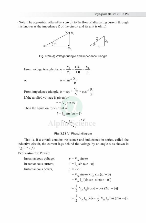
Single-phase AC Circuits 3.23
(Note: The opposition offered by a circuit to the flow of alternating current through it is known as the impedance Z of the circuit and its unit is ohm.)
VL
OVR
Z
R
XL
V
Fig. 3.23 (a) Voltage triangle and impedance triangle
From voltage triangle, tan f = VV
= I XI R
= XR
L
R
L L
or f = tan–1 XR
L
From impedance triangle, f = cos–1 VV
RZ
R = −cos 1
If the applied voltage is given by v = Vm sin wtThen the equation for current is i = Im sin (wt - f)
i
v
Fig. 3.23 (b) Phasor diagram
That is, if a circuit contains resistance and inductance in series, called the inductive circuit, the current lags behind the voltage by an angle f as shown in Fig. 3.23 (b).Expression for Power:
Instantaneous voltage, v = Vm sin wtInstantaneous current, i = I m sin (wt - f)Instantaneous power, p = v × i = Vm sin wt × Im sin (wt - f) = Vm Im [sin wt . sin(wt - f)]
= 12
Vm Im[cos f - cos (2wt - f)]
= 12
Vm Im cof - 12
Vm Im cos (2wt - f)
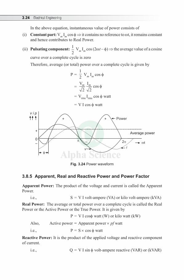
3.24 Electrical Engineering
In the above equation, instantaneous value of power consists of(i) Constant part: Vm Im cos f ⇒ it contains no reference to wt, it remains constant
and hence contributes to Real Power.
(ii) Pulsating component: 12
Vm Im cos (2wt - f) ⇒ the average value of a cosine
curve over a complete cycle is zero Therefore, average (or total) power over a complete cycle is given by
P = 12 Vm Im cos f
= V Im m
2 2cos f
= Vrms Irms cos f watt
= V I cos f watt
Power
Average power
t
iv
– 2
++
+
0–
v i p
Fig. 3.24 Power waveform
3.8.5 Apparent, Real and Reactive Power and Power Factor
Apparent Power: The product of the voltage and current is called the Apparent Power.
i.e., S = V I volt-ampere (VA) or kilo volt-ampere (kVA)Real Power: The average or total power over a complete cycle is called the Real Power or the Active Power or the True Power. It is given by
P = V I cosf watt (W) or kilo watt (kW)
Also, Active power = Apparent power × pf watt
i.e., P = S × cos f watt
Reactive Power: It is the product of the applied voltage and reactive component of current.
i.e., Q = V I sin f volt-ampere reactive (VAR) or (kVAR)
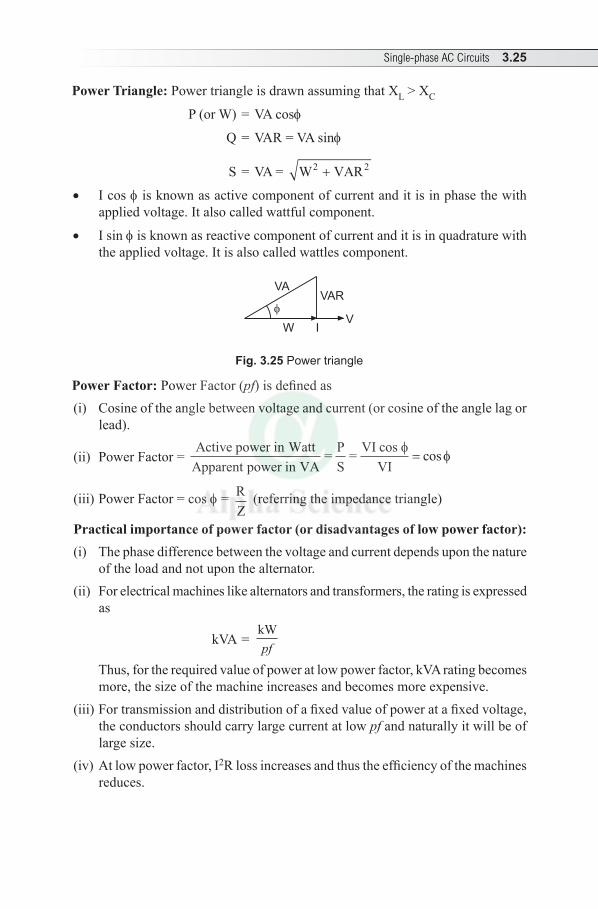
Single-phase AC Circuits 3.25
Power Triangle: Power triangle is drawn assuming that XL > XC
P (or W) = VA cosf
Q = VAR = VA sinf
S = VA = W VAR22 +
• I cos f is known as active component of current and it is in phase the with applied voltage. It also called wattful component.
• I sin f is known as reactive component of current and it is in quadrature with the applied voltage. It is also called wattles component.
W
VAVAR
VI
Fig. 3.25 Power triangle
Power Factor: Power Factor (pf) is defined as (i) Cosine of the angle between voltage and current (or cosine of the angle lag or
lead).
(ii) Power Factor = Active power in Watt
Apparent power in VA= P
S= VI cos
VIφ
φ= cos
(iii) Power Factor = cos f = RZ
(referring the impedance triangle)
Practical importance of power factor (or disadvantages of low power factor):(i) The phase difference between the voltage and current depends upon the nature
of the load and not upon the alternator.(ii) For electrical machines like alternators and transformers, the rating is expressed
as
kVA = kWpf
Thus, for the required value of power at low power factor, kVA rating becomes more, the size of the machine increases and becomes more expensive.
(iii) For transmission and distribution of a fixed value of power at a fixed voltage, the conductors should carry large current at low pf and naturally it will be of large size.
(iv) At low power factor, I2R loss increases and thus the efficiency of the machines reduces.
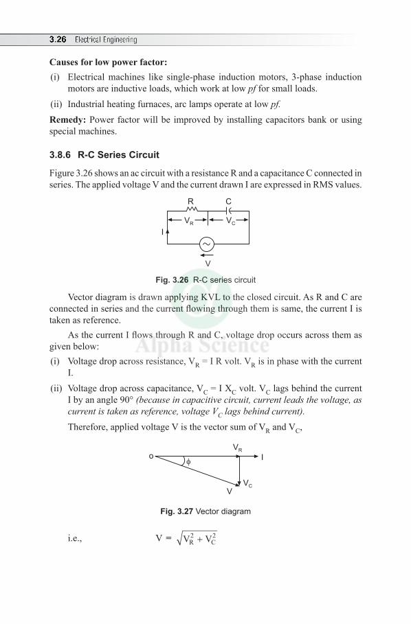
3.26 Electrical Engineering
Causes for low power factor:(i) Electrical machines like single-phase induction motors, 3-phase induction
motors are inductive loads, which work at low pf for small loads.(ii) Industrial heating furnaces, arc lamps operate at low pf. Remedy: Power factor will be improved by installing capacitors bank or using special machines.
3.8.6 R-C Series Circuit
Figure 3.26 shows an ac circuit with a resistance R and a capacitance C connected in series. The applied voltage V and the current drawn I are expressed in RMS values.
R
I
V
C
VCVR
Fig. 3.26 R-C series circuit
Vector diagram is drawn applying KVL to the closed circuit. As R and C are connected in series and the current flowing through them is same, the current I is taken as reference.
As the current I flows through R and C, voltage drop occurs across them as given below:(i) Voltage drop across resistance, VR = I R volt. VR is in phase with the current
I.(ii) Voltage drop across capacitance, VC = I XC volt. VC lags behind the current
I by an angle 90° (because in capacitive circuit, current leads the voltage, as current is taken as reference, voltage VC lags behind current). Therefore, applied voltage V is the vector sum of VR and VC,
oVR
VC
V
I
Fig. 3.27 Vector diagram
i.e., V = V VR C2 2+
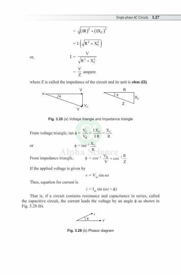
Single-phase AC Circuits 3.27
= ( ) ( )2 2CIR IX+
= I ( )2 2CR X+
or, I = V
R XC2 2+
= VZ
ampere
where Z is called the impedance of the circuit and its unit is ohm (Ω).
R
Z
XC
oV
VC
V
Fig. 3.28 (a) Voltage triangle and impedance triangle
From voltage triangle, tan f = VV
= I XI R
= XR
C
R
C C
or f = tan–1 XR
C
From impedance triangle, f = cos–1 VV
RZ
R = −cos 1
If the applied voltage is given by v = Vm sin wtThen, equation for current is i = Im sin (wt + f)That is, if a circuit contains resistance and capacitance in series, called
the capacitive circuit, the current leads the voltage by an angle f as shown in Fig. 3.28 (b).
i
v
Fig. 3.28 (b) Phasor diagram
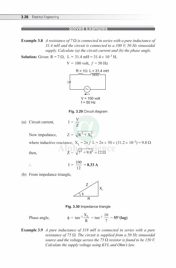
3.28 Electrical Engineering
Solved Examples
Example 3.8 A resistance of 7 W is connected in series with a pure inductance of 31.4 mH and the circuit is connected to a 100 V, 50 Hz sinusoidal supply. Calculate (a) the circuit current and (b) the phase angle.
Solution: Given: R = 7 Ω, L = 31.4 mH = 31.4 × 10⁻³ H, V = 100 volt, f = 50 Hz
R = 1
I
V = 100 voltf = 50 Hz
L = 31.4 mH
Fig. 3.29 Circuit diagram
(a) Circuit current, I = VZ
Now impedance, Z = R + X2L2
where inductive reactance, XL = 2p f L = 2p × 50 × (31.2 × 10–3) = 9.8 Ω
then, Z = 2 27 + 9.8 12= Ω
\ I = 10012
= 8.33 A
(b) From impedance triangle,
XL
Z
R
Fig. 3.30 Impedance triangle
Phase angle, f = tan–1 XR
L = tan–1 107
= 55°(lag)
Example 3.9 A pure inductance of 318 mH is connected in series with a pure resistance of 75 Ω. The circuit is supplied from a 50 Hz sinusoidal source and the voltage across the 75 Ω resistor is found to be 150 V. Calculate the supply voltage using KVL and Ohm’s law.
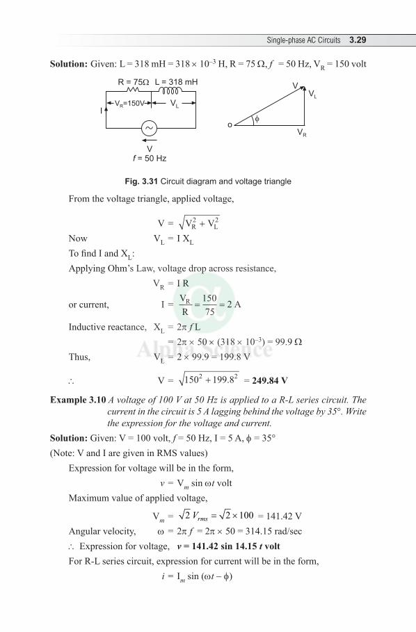
Single-phase AC Circuits 3.29
Solution: Given: L = 318 mH = 318 × 10–3 H, R = 75 Ω, f = 50 Hz, VR = 150 volt
R = 75
I
V= 50 Hzf
L = 318 mH
V =150VR VL
VL
VR
V
o
Fig. 3.31 Circuit diagram and voltage triangle
From the voltage triangle, applied voltage,
V = V VR L2 2+
Now VL = I XL
To find I and XL:Applying Ohm’s Law, voltage drop across resistance, VR = I R
or current, I = VR
AR = =15075
2
Inductive reactance, XL = 2p f L = 2p × 50 × (318 × 10–3) = 99.9 ΩThus, VL = 2 × 99.9 = 199.8 V
\ V = 150 199 82 2+ . = 249.84 V
Example 3.10 A voltage of 100 V at 50 Hz is applied to a R-L series circuit. The current in the circuit is 5 A lagging behind the voltage by 35°. Write the expression for the voltage and current.
Solution: Given: V = 100 volt, f = 50 Hz, I = 5 A, f = 35°(Note: V and I are given in RMS values)
Expression for voltage will be in the form, v = Vm sin wt volt Maximum value of applied voltage,
Vm = 2 2 100= ×rmsV = 141.42 VAngular velocity, w = 2p f = 2p × 50 = 314.15 rad/sec\ Expression for voltage, v = 141.42 sin 14.15 t voltFor R-L series circuit, expression for current will be in the form, i = Im sin (wt - f)
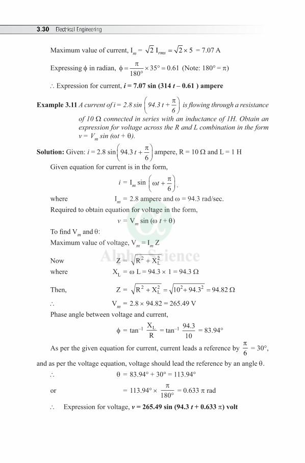
3.30 Electrical Engineering
Maximum value of current, Im = 2 I 2 5= ×rms = 7.07 A
Expressing f in radian, φ π=
°× ° =
18035 0 61. (Note: 180° = p)
\Expression for current, i = 7.07 sin (314 t – 0.61 ) ampere
Example 3.11 A current of i = 2.8 sin 94.3 t +6π
is flowing through a resistance
of 10 Ω connected in series with an inductance of 1H. Obtain an expression for voltage across the R and L combination in the form v = Vm sin (wt + q).
Solution: Given: i = 2.8 sin 94 36
. t +
π ampere, R = 10 Ω and L = 1 H
Given equation for current is in the form,
i = Im sin ωπt +
6 ,
where Im = 2.8 ampere and w = 94.3 rad/sec.Required to obtain equation for voltage in the form, v = Vm sin (w t + q)To find Vm and q:Maximum value of voltage, Vm = Im Z
Now Z = R X2L2+
where XL = w L = 94.3 × 1 = 94.3 Ω
Then, Z = R X L22 2 210 94 3 94 82+ = + =. . Ω
\ Vm = 2.8 × 94.82 = 265.49 VPhase angle between voltage and current,
f = tan–1 XR
L = tan–1 94.310
= 83.94°
As per the given equation for current, current leads a reference by 6p
= 30°,
and as per the voltage equation, voltage should lead the reference by an angle q.\ q = 83.94° + 30° = 113.94°
or = 113.94° × π
180° = 0.633 p rad
\ Expression for voltage, v = 265.49 sin (94.3 t + 0.633 p) volt
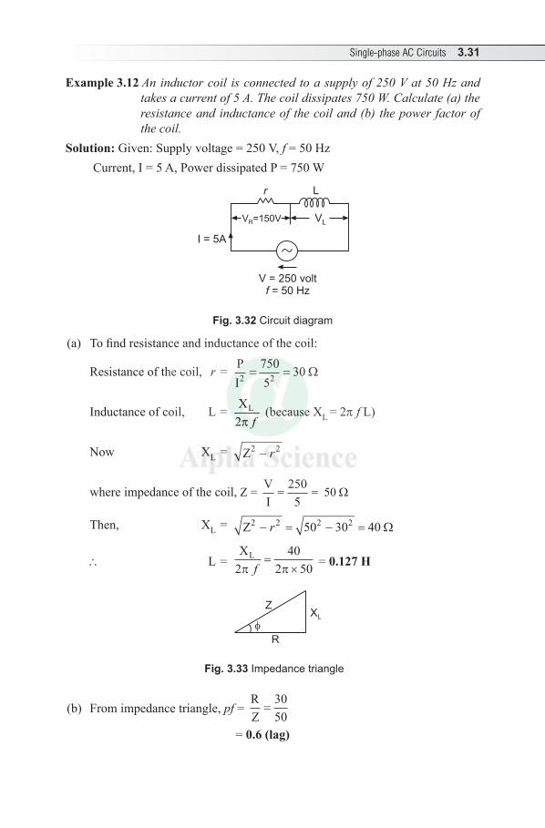
Single-phase AC Circuits 3.31
Example 3.12 An inductor coil is connected to a supply of 250 V at 50 Hz and takes a current of 5 A. The coil dissipates 750 W. Calculate (a) the resistance and inductance of the coil and (b) the power factor of the coil.
Solution: Given: Supply voltage = 250 V, f = 50 Hz Current, I = 5 A, Power dissipated P = 750 W
r
I = 5A
V = 250 volt= 50 Hzf
L
V =150VR VL
Fig. 3.32 Circuit diagram
(a) To find resistance and inductance of the coil:
Resistance of the coil, r = PI2 = =
7505
302 Ω
Inductance of coil, L = LX2 fp
(because XL = 2p f L)
Now XL = Z2 2- r
where impedance of the coil, Z = VI= =
2505
50 Ω
Then, XL = Z2 2 2 250 30 40− = − =r Ω
\ L = XL
240
2 50π πf=
× = 0.127 H
XL
Z
R
Fig. 3.33 Impedance triangle
(b) From impedance triangle, pf = RZ
=3050
= 0.6 (lag)
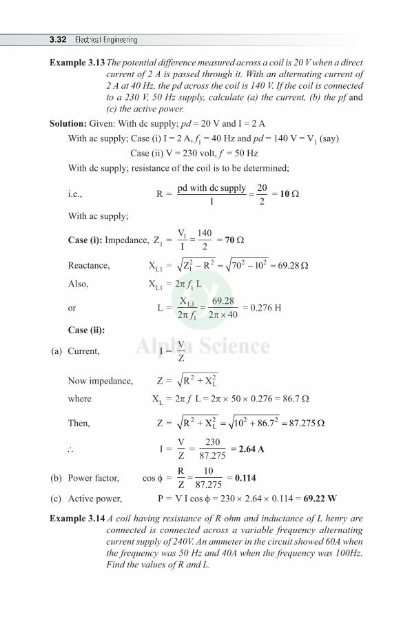
3.32 Electrical Engineering
Example 3.13 The potential difference measured across a coil is 20 V when a direct current of 2 A is passed through it. With an alternating current of 2 A at 40 Hz, the pd across the coil is 140 V. If the coil is connected to a 230 V, 50 Hz supply, calculate (a) the current, (b) the pf and (c) the active power.
Solution: Given: With dc supply; pd = 20 V and I = 2 A With ac supply; Case (i) I = 2 A, f1 = 40 Hz and pd = 140 V = V1 (say) Case (ii) V = 230 volt, f = 50 HzWith dc supply; resistance of the coil is to be determined;
i.e., R = pd with dc supply 20I 2
= = 10 Ω
With ac supply;
Case (i): Impedance, Z1 = VI1 =
1402
= 70 Ω
Reactance, XL1 = 2 2 2 21Z R 70 10 69.28- = - = Ω
Also, XL1 = 2p f1 L
or L = X
L1
269 28
2 401π πf=
×.
= 0.276 H
Case (ii):
(a) Current, I = VZ
Now impedance, Z = R + X2L2
where XL = 2p f L = 2p × 50 × 0.276 = 86.7 Ω
Then, Z = 2 2 2 2LR + X 10 86.7 87.275= + = Ω
\ I = VZ
= 230
87.275 = 2.64 A
(b) Power factor, cos f = R 10Z 87.275
= = 0.114
(c) Active power, P = V I cos f = 230 × 2.64 × 0.114 = 69.22 W
Example 3.14 A coil having resistance of R ohm and inductance of L henry are connected is connected across a variable frequency alternating current supply of 240V. An ammeter in the circuit showed 60A when the frequency was 50 Hz and 40A when the frequency was 100Hz. Find the values of R and L.
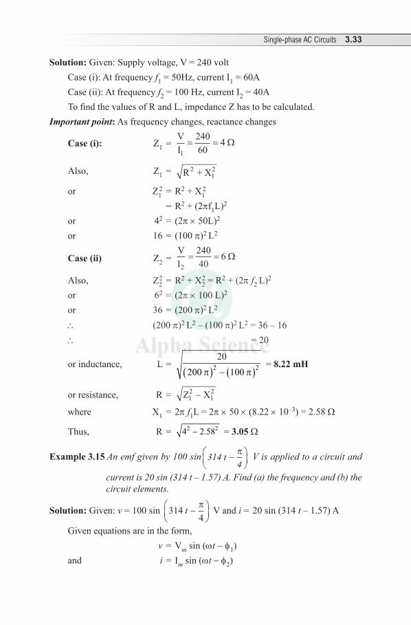
Single-phase AC Circuits 3.33
Solution: Given: Supply voltage, V = 240 voltCase (i): At frequency f1 = 50Hz, current I1 = 60ACase (ii): At frequency f2 = 100 Hz, current I2 = 40ATo find the values of R and L, impedance Z has to be calculated.
Important point: As frequency changes, reactance changes
Case (i): Z1 = VI1
24060
4= = Ω
Also, Z1 = R + X212
or Z12 = R2 + X1
2 = R2 + (2pf1L)2 or 42 = (2p × 50L)2
or 16 = (100 p)2 L2
Case (ii) Z2 = VI2
24040
6= = Ω
Also, Z22 = R2 + X2
2 = R2 + (2p f2 L)2 or 62 = (2p × 100 L)2
or 36 = (200 p)2 L2
\ (200 p)2 L2 – (100 p)2 L2 = 36 – 16 \ = 20
or inductance, L = ( ) ( )2 2
20200 100p - p
= 8.22 mH
or resistance, R = Z X12
12-
where X1 = 2p f1L = 2p × 50 × (8.22 × 10–3) = 2.58 Ω
Thus, R = 2 24 2.58- = 3.05 Ω
Example 3.15 An emf given by 100 sin 314 t4
−
π V is applied to a circuit and
current is 20 sin (314 t – 1.57) A. Find (a) the frequency and (b) the circuit elements.
Solution: Given: v = 100 sin 3144
t −
π V and i = 20 sin (314 t – 1.57) A
Given equations are in the form, v = Vm sin (wt - f1) and i = I m sin (wt - f2)
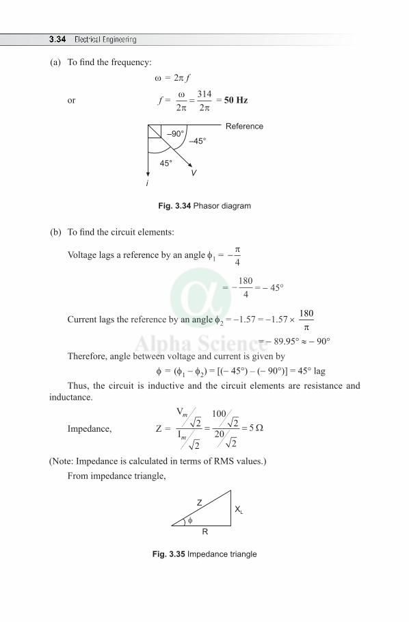
3.34 Electrical Engineering
(a) To find the frequency: w = 2p f
or f = ωπ π2
3142
= = 50 Hz
V
–45°
45°
–90°
i
Reference
Fig. 3.34 Phasor diagram
(b) To find the circuit elements:
Voltage lags a reference by an angle f1 = − π4
= -180
4= - 45°
Current lags the reference by an angle f2 = -1.57 = -1.57 × 180p
= - 89.95° ≈ - 90°Therefore, angle between voltage and current is given by f = (f1 - f2) = [(- 45°) – (- 90°)] = 45° lagThus, the circuit is inductive and the circuit elements are resistance and
inductance.
Impedance, Z =
V
I
m
m
2
2
1002
202
5= = Ω
(Note: Impedance is calculated in terms of RMS values.)From impedance triangle,
XL
Z
R
Fig. 3.35 Impedance triangle
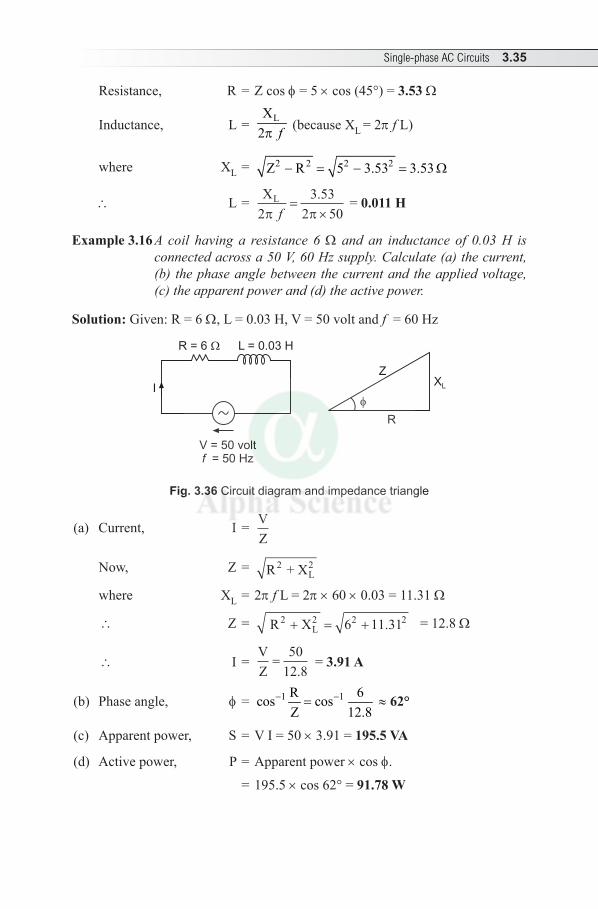
Single-phase AC Circuits 3.35
Resistance, R = Z cos f = 5 × cos (45°) = 3.53 Ω
Inductance, L = LX2 fp
(because XL = 2p f L)
where XL = 2 2 2 2Z R 5 3.53 3.53- = - = Ω
\ L = XL
23 53
2 50π πf=
×. = 0.011 H
Example 3.16 A coil having a resistance 6 Ω and an inductance of 0.03 H is connected across a 50 V, 60 Hz supply. Calculate (a) the current, (b) the phase angle between the current and the applied voltage, (c) the apparent power and (d) the active power.
Solution: Given: R = 6 Ω, L = 0.03 H, V = 50 volt and f = 60 Hz
R = 6
I
V = 50 volt= 50 Hzf
L = 0.03 H
XL
R
Z
Fig. 3.36 Circuit diagram and impedance triangle
(a) Current, I = VZ
Now, Z = R + X2L2
where XL = 2p f L = 2p × 60 × 0.03 = 11.31 Ω
\ Z = R X 2L2+ = +6 11 312 2. = 12.8 Ω
\ I = VZ
=50
12 8. = 3.91 A
(b) Phase angle, f = 1 1R 6cos cosZ 12.8
- -= ≈ 62°
(c) Apparent power, S = V I = 50 × 3.91 = 195.5 VA
(d) Active power, P = Apparent power × cos f.
= 195.5 × cos 62° = 91.78 W
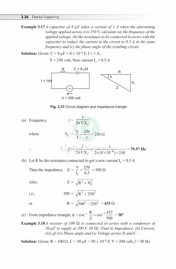
3.36 Electrical Engineering
Example 3.17 A capacitor of 8 µF takes a current of 1 A when the alternating voltage applied across it is 250 V, calculate (a) the frequency of the applied voltage, (b) the resistance to be connected in series with the capacitor to reduce the current in the circuit to 0.5 A at the same frequency and (c) the phase angle of the resulting circuit.
Solution: Given: C = 8 µF = 8 × 10⁻⁶ F, I = 1 A, V = 250 volt, New current I1 = 0.5 A
R
I = 1A
V = 250 volt
C = 8 H
XL
R
Z
Fig. 3.37 Circuit diagram and impedance triangle
(a) Frequency, f = 1
2 CXCp
where XC = VI= =
2501
250Ω
\ f = 12
12 8 10 2506π πCXC
=× ×−( )
= 79.57 Hz
(b) Let R be the resistance connected to get a new current I1 = 0.5 A
Then the impedance, Z = VI
2500.51
= = 500 Ω
Also, Z = R X2C2+
i.e., 500 = R 2502 2+
or R = 500 2502 2- = 433 Ω
(c) From impedance triangle, f = cos–1 RZ
cos 433500
1= −
= 30°
Example 3.18 A resistor of 100 Ω is connected in series with a condenser of 50 µF to supply at 200 V, 50 Hz. Find (i) Impedance, (ii) Current, (iii) pf (iv) Phase angle and (v) Voltage across R and C.
Solution: Given: R = 100 Ω, C = 50 µF = 50 × 10–6 F, V = 200 volt, f = 50 Hz

Single-phase AC Circuits 3.37
~
R =100
I
V = 250 volt= 50 Hzf
C = 50 F
XC
R
Z
VR VC
Fig. 3.38 Circuit diagram and impedance triangle
(i) Impedance, Z = R XC2 2+
where XC = ( )6
1 1 63.662 C 2 50 50 10f -
= = Ωp p × × ×
\ Z = 100 63 662 2+ . = 118.54 Ω
(ii) Current, I = VZ
=200
118 54. = 1.687 A
(iii) Power factor, cos f = RZ
=100
118 54. = 0.84
(iv) Phase angle, f = cos–1(0.84) = 32.85° (v) Voltage across Resistance, VR = I R = 1.687 × 100 = 168.7 V Voltage across Capacitance, VC = I XC = 1.687 × 63.66 = 107.39 V
3.8.7 R-L-C Series Circuit
Figure 3.39 shows an ac circuit with a Resistance R, an Inductance L and a Capacitance C connected in series. The applied voltage V and the current drawn I are expressed in RMS values.
I
V
R L C
vRvL vC
Fig. 3.39 R-L-C Series circuit
Vector diagram is drawn applying KVL to the closed circuit. As R, L and C are connected in series and the current flowing through them is same, current I is taken as reference.
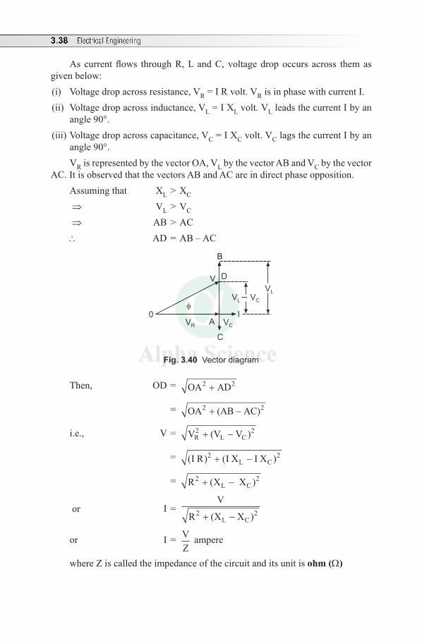
3.38 Electrical Engineering
As current flows through R, L and C, voltage drop occurs across them as given below:(i) Voltage drop across resistance, VR = I R volt. VR is in phase with current I. (ii) Voltage drop across inductance, VL = I XL volt. VL leads the current I by an
angle 90°. (iii) Voltage drop across capacitance, VC = I XC volt. VC lags the current I by an
angle 90°.VR is represented by the vector OA, VL by the vector AB and VC by the vector
AC. It is observed that the vectors AB and AC are in direct phase opposition.Assuming that XL > XC ⇒ VL > VC ⇒ AB > AC\ AD = AB – AC
0
VR VCA
C
V VL C–
V D
B
VL
I
Fig. 3.40 Vector diagram
Then, OD = OA AD2 2+
= OA (AB AC)2 2+ −
i.e., V = V (VR2
L+ − V )C2
= ( ) ( )I R I X I X2L C+ − 2
= R X XL C2 2+ −( )
or I = V
R X XL C2 2+ −( )
or I = VZ
ampere
where Z is called the impedance of the circuit and its unit is ohm (Ω)
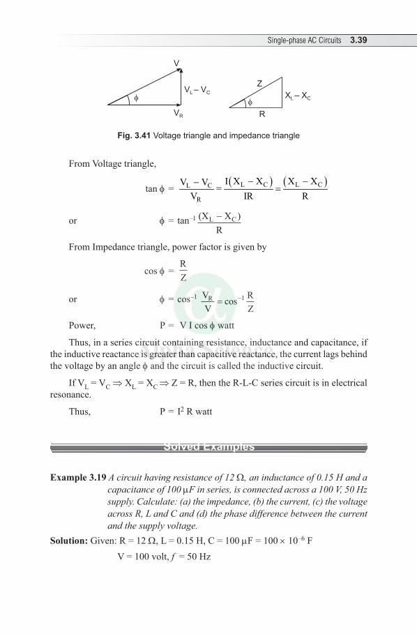
Single-phase AC Circuits 3.39
Z
R
V – VL C
VR
V
X – XL C
Fig. 3.41 Voltage triangle and impedance triangle
From Voltage triangle,
tan f = ( ) ( )L C L CL C
R
I X X X XV V=
V IR R- --
=
or f = tan–1 (X XR
L C- )
From Impedance triangle, power factor is given by
cos f = RZ
or f = cos–1 VV
RZ
R = −cos 1
Power, P = V I cos f watt
Thus, in a series circuit containing resistance, inductance and capacitance, if the inductive reactance is greater than capacitive reactance, the current lags behind the voltage by an angle f and the circuit is called the inductive circuit.
If VL = VC ⇒ XL = XC ⇒ Z = R, then the R-L-C series circuit is in electrical resonance.
Thus, P = I2 R watt
Solved Examples
Example 3.19 A circuit having resistance of 12 Ω, an inductance of 0.15 H and a capacitance of 100 µF in series, is connected across a 100 V, 50 Hz supply. Calculate: (a) the impedance, (b) the current, (c) the voltage across R, L and C and (d) the phase difference between the current and the supply voltage.
Solution: Given: R = 12 Ω, L = 0.15 H, C = 100 µF = 100 × 10–6 F V = 100 volt, f = 50 Hz
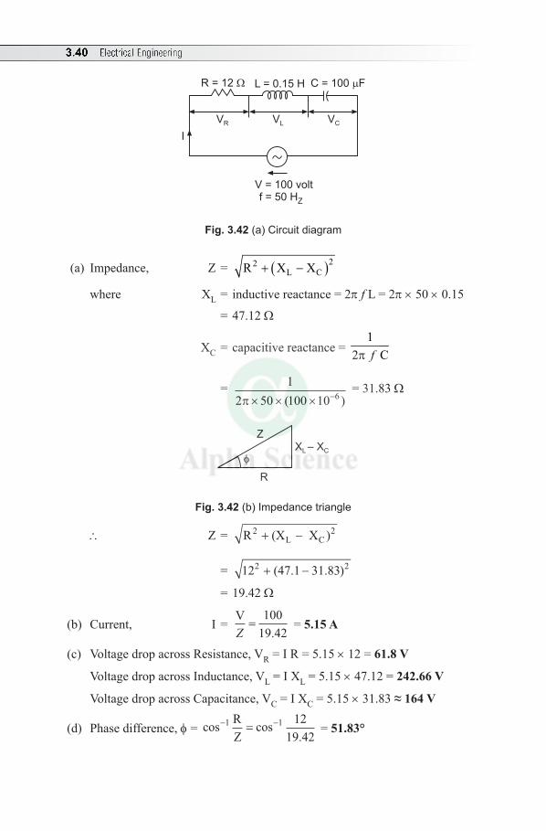
3.40 Electrical Engineering
I
V = 100 voltf = 50 HZ
R = 12 L = 0.15 H C = 100 F
VR VL VC
Fig. 3.42 (a) Circuit diagram
(a) Impedance, Z = ( )22L CR X X+ -
where XL = inductive reactance = 2p f L = 2p × 50 × 0.15
= 47.12 Ω
XC = capacitive reactance = 1
2 Cfp
= 12 50 100 10 6π× × × −( )
= 31.83 Ω
XL – XC
Z
R
Fig. 3.42 (b) Impedance triangle
\ Z = R (X X2L C+ − )2
= 12 (47.1 31.832 + − )2
= 19.42 Ω
(b) Current, I = V
.Z=
10019 42
= 5.15 A
(c) Voltage drop across Resistance, VR = I R = 5.15 × 12 = 61.8 V
Voltage drop across Inductance, VL = I XL = 5.15 × 47.12 = 242.66 V
Voltage drop across Capacitance, VC = I XC = 5.15 × 31.83 ≈ 164 V
(d) Phase difference, f = cos cos.
− −=1 1 1219 42
RZ
= 51.83°
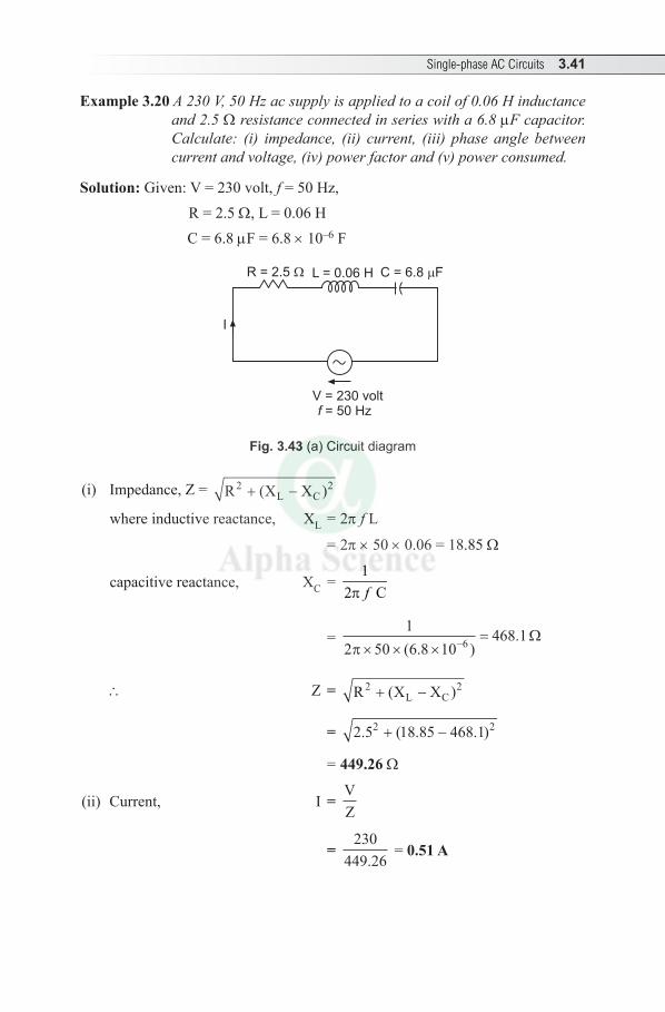
Single-phase AC Circuits 3.41
Example 3.20 A 230 V, 50 Hz ac supply is applied to a coil of 0.06 H inductance and 2.5 Ω resistance connected in series with a 6.8 µF capacitor. Calculate: (i) impedance, (ii) current, (iii) phase angle between current and voltage, (iv) power factor and (v) power consumed.
Solution: Given: V = 230 volt, f = 50 Hz, R = 2.5 Ω, L = 0.06 H
C = 6.8 µF = 6.8 × 10⁻⁶ F
I
V = 230 voltf = 50 Hz
R = 2.5 L = 0.06 H C = 6.8 F
Fig. 3.43 (a) Circuit diagram
(i) Impedance, Z = R X XL C2 2+ −( )
where inductive reactance, XL = 2p f L
= 2p × 50 × 0.06 = 18.85 Ω
capacitive reactance, XC = 1
2 Cfp
= 1
2 50 6 8 10468 16π× × ×
=−( . ). Ω
\ Z = R X XL C2 2+ −( )
= 2 5 18 85 468 12 2. ( . . )+ −
= 449.26 Ω
(ii) Current, I = VZ
= 230
449.26 = 0.51 A
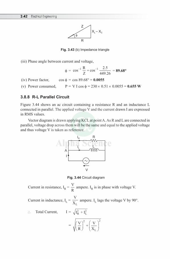
3.42 Electrical Engineering
XL – XC
Z
R
Fig. 3.43 (b) Impedance triangle
(iii) Phase angle between current and voltage,
f = cos cos ..
- -=1 1 2 5449 26
RZ
= 89.68°
(iv) Power factor, cos f = cos 89.68° = 0.0055 (v) Power consumed, P = V I cos f = 230 × 0.51 × 0.0055 = 0.655 W
3.8.8 R-L Parallel Circuit
Figure 3.44 shows an ac circuit containing a resistance R and an inductance L connected in parallel. The applied voltage V and the current drawn I are expressed in RMS values.
Vector diagram is drawn applying KCL at point A. As R and L are connected in parallel, voltage drop across them will be the same and equal to the applied voltage and thus voltage V is taken as reference.
AI
V
IR
IL
R
L
Fig. 3.44 Circuit diagram
Current in resistance, IR = VR
ampere. IR is in phase with voltage V.
Current in inductance, IL = V
XL ampere. IL lags the voltage V by 90°.
\ Total Current, I = I + IR2
L2
= VR
+ VX
2
L
2
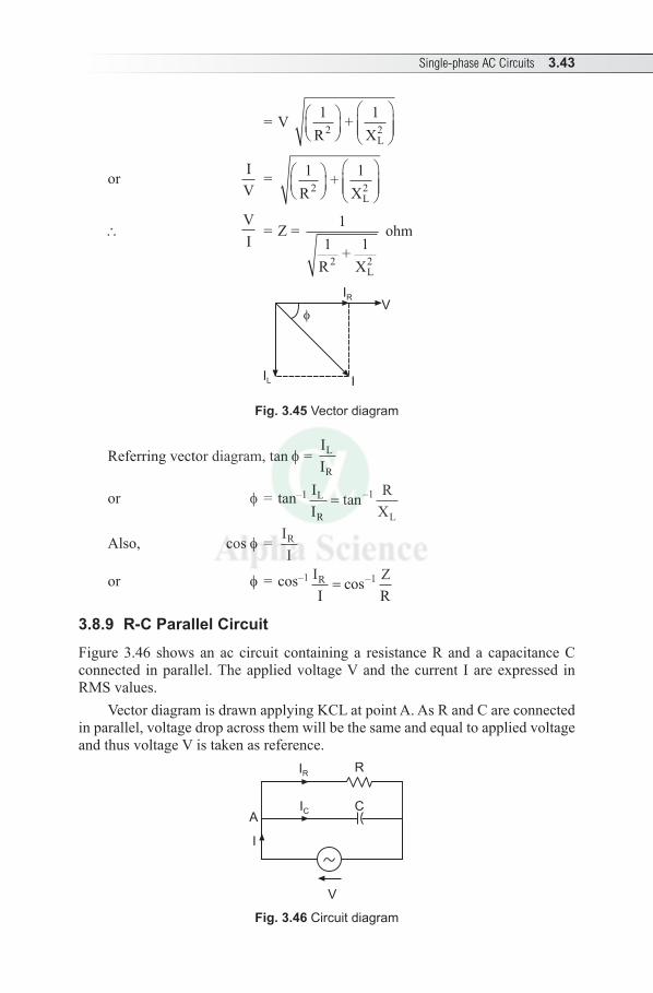
Single-phase AC Circuits 3.43
= V 1R
+ 1X2
L2
or IV
= 1R
+ 1X2
L2
\ VI
= Z = 11
R+ 1
X2L2
ohm
IL I
IR
V
Fig. 3.45 Vector diagram
Referring vector diagram, tan f = II
L
R
or f = tan–1 II
RX
L
R L= −tan 1
Also, cos f = IIR
or f = cos–1 II
ZR
R = −cos 1
3.8.9 R-C Parallel Circuit
Figure 3.46 shows an ac circuit containing a resistance R and a capacitance C connected in parallel. The applied voltage V and the current I are expressed in RMS values.
Vector diagram is drawn applying KCL at point A. As R and C are connected in parallel, voltage drop across them will be the same and equal to applied voltage and thus voltage V is taken as reference.
A
I
V
IR
IC
R
C
Fig. 3.46 Circuit diagram
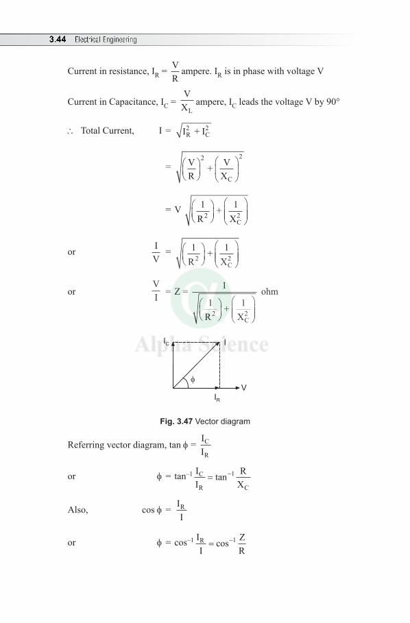
3.44 Electrical Engineering
Current in resistance, IR = VR
ampere. IR is in phase with voltage V
Current in Capacitance, IC = V
XLampere, IC leads the voltage V by 90°
\ Total Current, I = I + IR2
C2
= VR
+ VX
2
C
2
= V 1R
+ 1X2
C2
or IV
= 1R
+ 1X2
C2
or VI = Z = 1
1R
+ 1X2
C2
ohm
IC I
IR
V
Fig. 3.47 Vector diagram
Referring vector diagram, tan f = II
C
R
or f = tan–1 II
RX
C
R C= −tan 1
Also, cos f = IIR
or f = cos–1 II
ZR
R = −cos 1
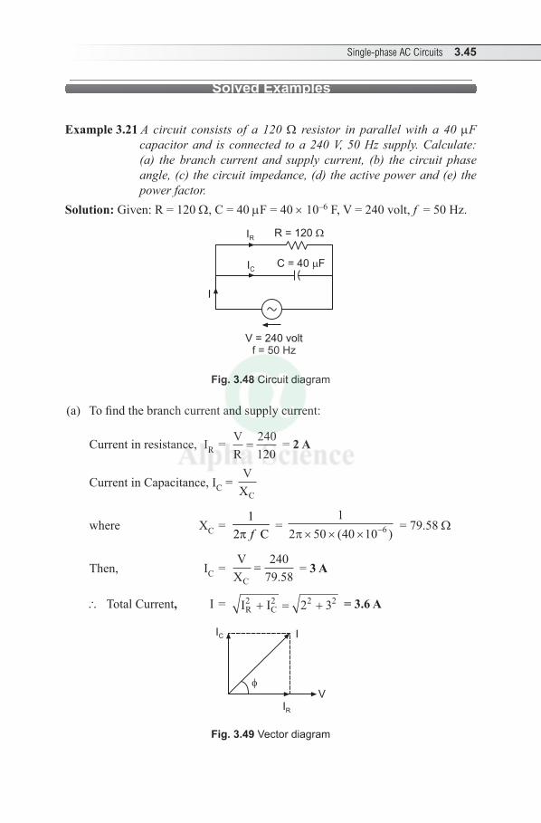
Single-phase AC Circuits 3.45
Solved Examples
Example 3.21 A circuit consists of a 120 Ω resistor in parallel with a 40 µF capacitor and is connected to a 240 V, 50 Hz supply. Calculate: (a) the branch current and supply current, (b) the circuit phase angle, (c) the circuit impedance, (d) the active power and (e) the power factor.
Solution: Given: R = 120 Ω, C = 40 µF = 40 × 10–6 F, V = 240 volt, f = 50 Hz.
I
V = 240 voltf = 50 Hz
IR
IC
R = 120
C = 40 F
Fig. 3.48 Circuit diagram
(a) To find the branch current and supply current:
Current in resistance, IR = VR
=240120
= 2 A
Current in Capacitance, IC = V
XC
where XC = 1
2 Cfp =
12 50 40 10 6π× × × −( )
= 79.58 Ω
Then, IC = V
XC=
24079 58.
= 3 A
\ Total Current, I = I IR2
C2+ = +2 32 2 = 3.6 A
IC I
IR
V
Fig. 3.49 Vector diagram
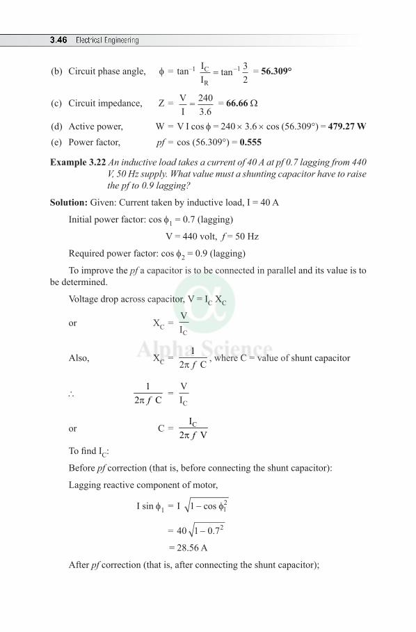
3.46 Electrical Engineering
(b) Circuit phase angle, f = tan–1 II
C
R= −tan 1 3
2 = 56.309°
(c) Circuit impedance, Z = VI
= 2403.6
= 66.66 Ω
(d) Active power, W = V I cos f = 240 × 3.6 × cos (56.309°) = 479.27 W(e) Power factor, pf = cos (56.309°) = 0.555
Example 3.22 An inductive load takes a current of 40 A at pf 0.7 lagging from 440 V, 50 Hz supply. What value must a shunting capacitor have to raise the pf to 0.9 lagging?
Solution: Given: Current taken by inductive load, I = 40 A
Initial power factor: cos f1 = 0.7 (lagging)
V = 440 volt, f = 50 Hz
Required power factor: cos f2 = 0.9 (lagging)
To improve the pf a capacitor is to be connected in parallel and its value is to be determined.
Voltage drop across capacitor, V = IC XC
or XC = VIC
Also, XC = 1
2 Cfp, where C = value of shunt capacitor
\ 1
2 Cfp =
VIC
or C = CI2 Vfp
To find IC:
Before pf correction (that is, before connecting the shunt capacitor):
Lagging reactive component of motor,
I sin f1 = I 1 12− cos φ
= 40 1 0 72- .
= 28.56 A
After pf correction (that is, after connecting the shunt capacitor);
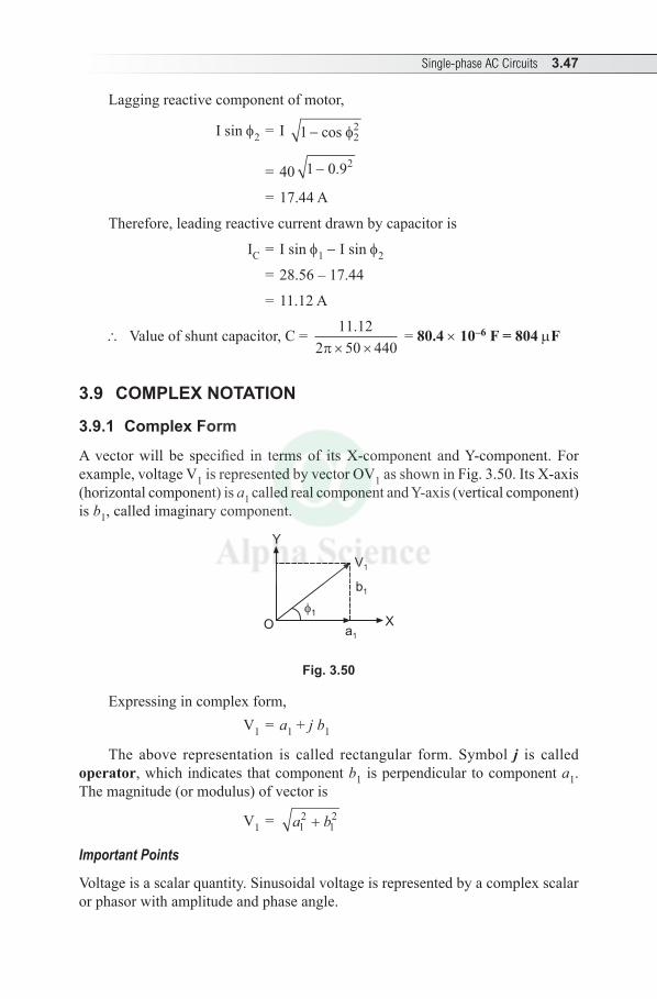
Single-phase AC Circuits 3.47
Lagging reactive component of motor,
I sin f2 = I 1 22− cos φ
= 40 1 0 92- .
= 17.44 A
Therefore, leading reactive current drawn by capacitor is
IC = I sin f1 - I sin f2
= 28.56 – 17.44
= 11.12 A
\ Value of shunt capacitor, C = 11 122 50 440
.π× ×
= 80.4 × 10⁻⁶ F = 804 µF
3.9 COMPLEX NOTATION
3.9.1 Complex Form
A vector will be specified in terms of its X-component and Y-component. For example, voltage V1 is represented by vector OV1 as shown in Fig. 3.50. Its X-axis (horizontal component) is a1 called real component and Y-axis (vertical component) is b1, called imaginary component.
Y
Oa1
1X
b1
V1
Fig. 3.50
Expressing in complex form, V1 = a1 + j b1
The above representation is called rectangular form. Symbol j is called operator, which indicates that component b1 is perpendicular to component a1. The magnitude (or modulus) of vector is
V1 = a b12
12+
Important Points
Voltage is a scalar quantity. Sinusoidal voltage is represented by a complex scalar or phasor with amplitude and phase angle.
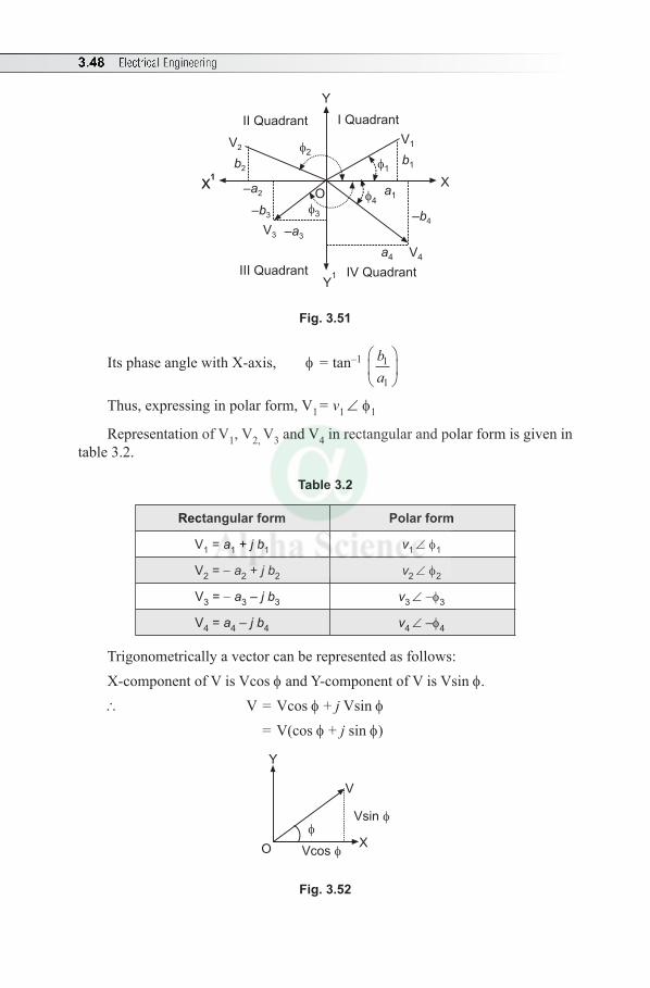
3.48 Electrical Engineering
II Quadrant I Quadrant
V2
b2
–a2
–b3
V3 –a3
3
2
1b1
V1
O a14
–b4
a4 V4
III Quadrant IV Quadrant
Y
Y1
X1
X1
X
Fig. 3.51
Its phase angle with X-axis, f = tan–1 ba
1
1
Thus, expressing in polar form, V1 = v1 ∠ f1
Representation of V1, V2, V3 and V4 in rectangular and polar form is given in table 3.2.
Table 3.2
Rectangular form Polar form
V1 = a1 + j b1 v1 ∠ f1
V2 = - a2 + j b2 v2 ∠ f2
V3 = - a3 – j b3 v3 ∠ -f3
V4 = a4 – j b4 v4 ∠ –f4
Trigonometrically a vector can be represented as follows: X-component of V is Vcos f and Y-component of V is Vsin f.\ V = Vcos f + j Vsin f = V(cos f + j sin f)
Y
V
XO Vcos
Vsin
Fig. 3.52
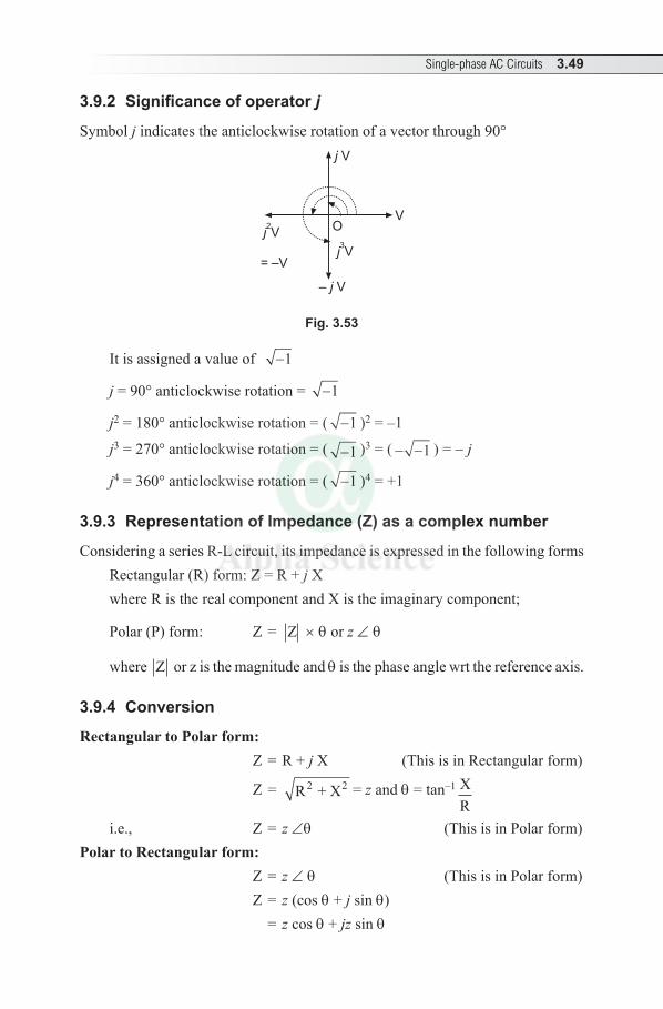
Single-phase AC Circuits 3.49
3.9.2 Significance of operator j
Symbol j indicates the anticlockwise rotation of a vector through 90°
O
j V
j2V
j3V
= –V
V
– j V
Fig. 3.53
It is assigned a value of -1
j = 90° anticlockwise rotation = -1
j2 = 180° anticlockwise rotation = ( -1 )2 = –1
j3 = 270° anticlockwise rotation = ( -1 )3 = ( - -1 ) = - j
j4 = 360° anticlockwise rotation = ( -1 )4 = +1
3.9.3 Representation of Impedance (Z) as a complex number
Considering a series R-L circuit, its impedance is expressed in the following forms Rectangular (R) form: Z = R + j X where R is the real component and X is the imaginary component;
Polar (P) form: Z = Z × q or z ∠ q
where Z or z is the magnitude and q is the phase angle wrt the reference axis.
3.9.4 Conversion
Rectangular to Polar form: Z = R + j X (This is in Rectangular form)
Z = R + X2 2 = z and q = tan–1 XR
i.e., Z = z ∠q (This is in Polar form)Polar to Rectangular form:
Z = z ∠ q (This is in Polar form)
Z = z (cos q + j sin q) = z cos q + jz sin q
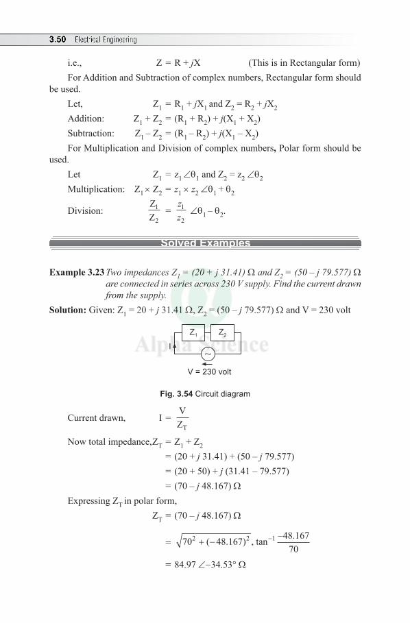
3.50 Electrical Engineering
i.e., Z = R + jX (This is in Rectangular form)For Addition and Subtraction of complex numbers, Rectangular form should
be used. Let, Z1 = R1 + jX1 and Z2 = R2 + jX2 Addition: Z1 + Z2 = (R1 + R2) + j(X1 + X2)Subtraction: Z1 – Z2 = (R1 – R2) + j(X1 – X2)For Multiplication and Division of complex numbers, Polar form should be
used.Let Z1 = z1 ∠q1 and Z2 = z2 ∠q2
Multiplication: Z1 × Z2 = z1 × z2 ∠q1 + q2
Division: ZZ
1
2 =
zz
1
2 ∠q1 – q2.
Solved Examples
Example 3.23 Two impedances Z1 = (20 + j 31.41) Ω and Z2 = (50 – j 79.577) Ω are connected in series across 230 V supply. Find the current drawn from the supply.
Solution: Given: Z1 = 20 + j 31.41 Ω, Z2 = (50 – j 79.577) Ω and V = 230 volt
I
Z1 Z2
V = 230 volt
Fig. 3.54 Circuit diagram
Current drawn, I = VZT
Now total impedance, ZT = Z1 + Z2 = (20 + j 31.41) + (50 – j 79.577) = (20 + 50) + j (31.41 – 79.577) = (70 – j 48.167) ΩExpressing ZT in polar form, ZT = (70 – j 48.167) Ω
= 70 48 167 48 16770
2 2 1+ −−−( . ) , tan .
= 84.97 ∠-34.53° Ω
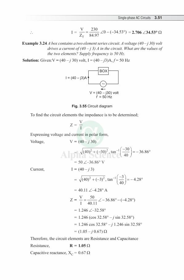
Single-phase AC Circuits 3.51
\ I = VZT
= ∠ − − °230
84 970 34 53
.( . ) = 2.706 ∠34.53° Ω
Example 3.24 A box contains a two element series circuit. A voltage (40 – j 30) volt drives a current of (40 – j 3) A in the circuit. What are the values of the two elements? Supply frequency is 50 Hz.
Solution: Given: V = (40 – j 30) volt, I = (40 – j3)A, f = 50 Hz
BOX
V = (40 – j30) volt= 50 Hzf
I = (40 – j3)A
Fig. 3.55 Circuit diagram
To find the circuit elements the impedance is to be determined;
Z = VI
Expressing voltage and current in polar form,
Voltage, V = (40 – j 30)
= ( ) ( ) , tan .40 30 3040
36 862 2 1+ −−
= − °−
= 50 ∠–36.86° V
Current, I = (40 – j 3)
= ( ) ( ) , tan .40 3 340
4 282 2 1+ −−
= − °−
= 40.11 ∠–4.28° A
Z = VI= ∠ − ° − − °
5040 11
36 86 4 28.
. ( . )
= 1.246 ∠–32.58°
= 1.246 (cos 32.58° – j sin 32.58°)
= 1.246 cos 32.58° – j 1.246 sin 32.58°
= (1.05 – j 0.67) Ω
Therefore, the circuit elements are Resistance and Capacitance
Resistance, R = 1.05 ΩCapacitive reactance, XC = 0.67 Ω
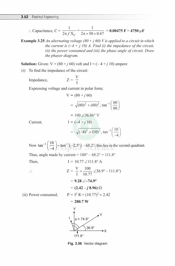
3.52 Electrical Engineering
\Capacitance, C = 1
21
2 50 0 67π π X=
Cf × × . = 0.00475 F = 4750 µF
Example 3.25 An alternating voltage (80 + j 60) V is applied to a circuit in which the current is (-4 + j 10) A. Find (i) the impedance of the circuit, (ii) the power consumed and (iii) the phase angle of circuit. Draw the phasor diagram.
Solution: Given: V = (80 + j 60) volt and I = (- 4 + j 10) ampere(i) To find the impedance of the circuit:
Impedance, Z = VI
Expressing voltage and current in polar form;
V = (80 + j 60)
= ( ) ( ) , tan80 60 6080
2 2 1+
−
= 100 ∠36.86° V
Current, I = (-4 + j 10)
= ( ) ( ) , tan− +−
−4 10 104
2 2 1
Now ( )1 110 tan tan 2.54
- - = - ° - – 68.2°; this lies in the second quadrant.
Thus, angle made by current = 180° – 68.2° = 111.8°
Then, I = 10.77 ∠111.8° A
\ Z = VI= ∠ ° − °
10010 77
36 9 111 8.
. . )
= 9.28 ∠–74.9°
= (2.42 – j 8.96) Ω
(ii) Power consumed, P = I2 R = (10.77)2 × 2.42
= 280.7 W
111.8°
36.9°
V
X
Y
I = 74.9°
Fig. 3.56 Vector diagram
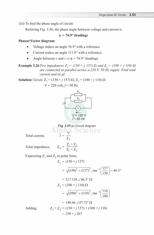
Single-phase AC Circuits 3.53
(iii) To find the phase angle of circuit: Referring Fig. 3.56, the phase angle between voltage and current is
f = 74.9° (leading)Phasor/Vector diagram:
• Voltage makes an angle 36.9° with a reference.• Current makes an angle 111.8° with a reference.• Angle between v and i ⇒ f = 74.9° (leading)
Example 3.26 Two impedances Z1 = (150 + j 157) Ω and Z2 = (100 + j 110) Ω are connected in parallel across a 220 V, 50 Hz supply. Find total current and its pf.
Solution: Given: Z1 = (150 + j 157) Ω, Z2 = (100 + j 110) Ω V = 220 volt, f = 50 Hz
I
V = 220 V= 50 Hzf
z1
z2
Fig. 3.57(a) Circuit diagram
Total current, I = VZT
Total impedance, Z T = Z × ZZ + Z
1 2
1 2
Expressing Z1 and Z2 in polar form, Z1 = (150 + j 157)
= ( ) ( ) , tan .150 157 157150
46 32 2 1+
= °−
= 217.138 ∠46.3° Ω Z2 = (100 + j 110) Ω
= ( ) ( ) , tan100 110 110100
2 2 1+
−
= 148.66 ∠47.72° Ω Adding, Z1 + Z2 = (150 + j 157) + (100 + j 110) = 250 + j 267
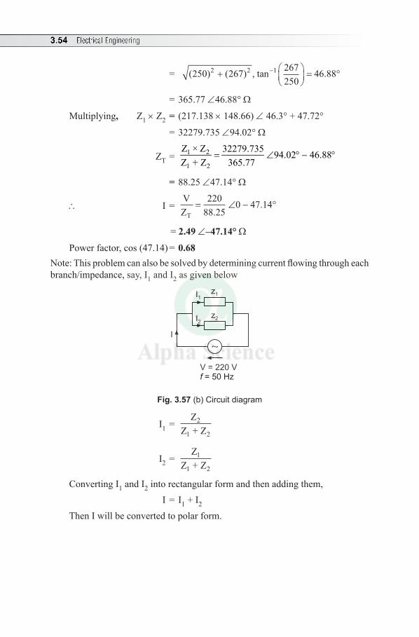
3.54 Electrical Engineering
= ( ) ( ) , tan .250 267 267250
46 882 2 1+
= °−
= 365.77 ∠46.88° Ω
Multiplying, Z1 × Z2 = (217.138 × 148.66) ∠ 46.3° + 47.72°
= 32279.735 ∠94.02° Ω
ZT = 1 2
1 2
Z × Z 32279.735 94.02 46.88Z + Z 365.77
= ∠ ° - °
= 88.25 ∠47.14° Ω
\ I = VZT
= ∠ − °220
88 250 47 14
..
= 2.49 ∠–47.14° Ω
Power factor, cos (47.14) = 0.68Note: This problem can also be solved by determining current flowing through each branch/impedance, say, I1 and I2 as given below
I
V = 220 V= 50 Hzf
z1I1
z2I2
Fig. 3.57 (b) Circuit diagram
I1 = Z
Z + Z2
1 2
I2 = Z
Z + Z1
1 2
Converting I1 and I2 into rectangular form and then adding them, I = I1 + I2
Then I will be converted to polar form.
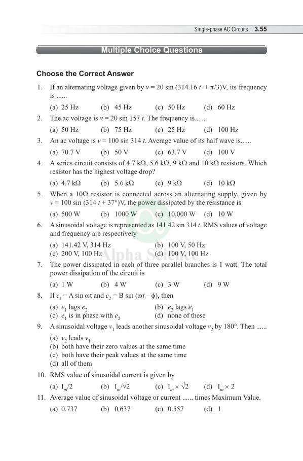
Single-phase AC Circuits 3.55
Multiple Choice Questions
Choose the Correct Answer
1. If an alternating voltage given by v = 20 sin (314.16 t + p/3) V, its frequency is ......(a) 25 Hz (b) 45 Hz (c) 50 Hz (d) 60 Hz
2. The ac voltage is v = 20 sin 157 t. The frequency is......(a) 50 Hz (b) 75 Hz (c) 25 Hz (d) 100 Hz
3. An ac voltage is v = 100 sin 314 t. Average value of its half wave is......(a) 70.7 V (b) 50 V (c) 63.7 V (d) 100 V
4. A series circuit consists of 4.7 kΩ, 5.6 kΩ, 9 kΩ and 10 kΩ resistors. Which resistor has the highest voltage drop?(a) 4.7 kΩ (b) 5.6 kΩ (c) 9 kΩ (d) 10 kΩ
5. When a 10Ω resistor is connected across an alternating supply, given by v = 100 sin (314 t + 37°) V, the power dissipated by the resistance is (a) 500 W (b) 1000 W (c) 10,000 W (d) 10 W
6. A sinusoidal voltage is represented as 141.42 sin 314 t. RMS values of voltage and frequency are respectively (a) 141.42 V, 314 Hz (b) 100 V, 50 Hz(c) 200 V, 100 Hz (d) 100 V, 100 Hz
7. The power dissipated in each of three parallel branches is 1 watt. The total power dissipation of the circuit is (a) 1 W (b) 4 W (c) 3 W (d) 9 W
8. If e1 = A sin wt and e2 = B sin (wt – f), then (a) e1 lags e2 (b) e2 lags e1(c) e1 is in phase with e2 (d) none of these
9. A sinusoidal voltage v1 leads another sinusoidal voltage v2 by 180°. Then ......(a) v2 leads v1(b) both have their zero values at the same time(c) both have their peak values at the same time(d) all of them
10. RMS value of sinusoidal current is given by(a) Im/2 (b) Im/√2 (c) Im × √2 (d) Im × 2
11. Average value of sinusoidal voltage or current ...... times Maximum Value.(a) 0.737 (b) 0.637 (c) 0.557 (d) 1
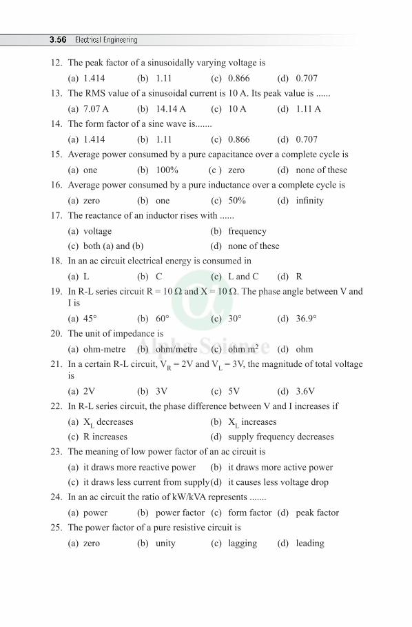
3.56 Electrical Engineering
12. The peak factor of a sinusoidally varying voltage is(a) 1.414 (b) 1.11 (c) 0.866 (d) 0.707
13. The RMS value of a sinusoidal current is 10 A. Its peak value is ......(a) 7.07 A (b) 14.14 A (c) 10 A (d) 1.11 A
14. The form factor of a sine wave is.......(a) 1.414 (b) 1.11 (c) 0.866 (d) 0.707
15. Average power consumed by a pure capacitance over a complete cycle is (a) one (b) 100% (c ) zero (d) none of these
16. Average power consumed by a pure inductance over a complete cycle is (a) zero (b) one (c) 50% (d) infinity
17. The reactance of an inductor rises with ......(a) voltage (b) frequency(c) both (a) and (b) (d) none of these
18. In an ac circuit electrical energy is consumed in (a) L (b) C (c) L and C (d) R
19. In R-L series circuit R = 10 Ω and X = 10 Ω. The phase angle between V and I is(a) 45° (b) 60° (c) 30° (d) 36.9°
20. The unit of impedance is (a) ohm-metre (b) ohm/metre (c) ohm m2 (d) ohm
21. In a certain R-L circuit, VR = 2V and VL = 3V, the magnitude of total voltage is(a) 2V (b) 3V (c) 5V (d) 3.6V
22. In R-L series circuit, the phase difference between V and I increases if(a) XL decreases (b) XL increases (c) R increases (d) supply frequency decreases
23. The meaning of low power factor of an ac circuit is (a) it draws more reactive power (b) it draws more active power(c) it draws less current from supply (d) it causes less voltage drop
24. In an ac circuit the ratio of kW/kVA represents .......(a) power (b) power factor (c) form factor (d) peak factor
25. The power factor of a pure resistive circuit is (a) zero (b) unity (c) lagging (d) leading
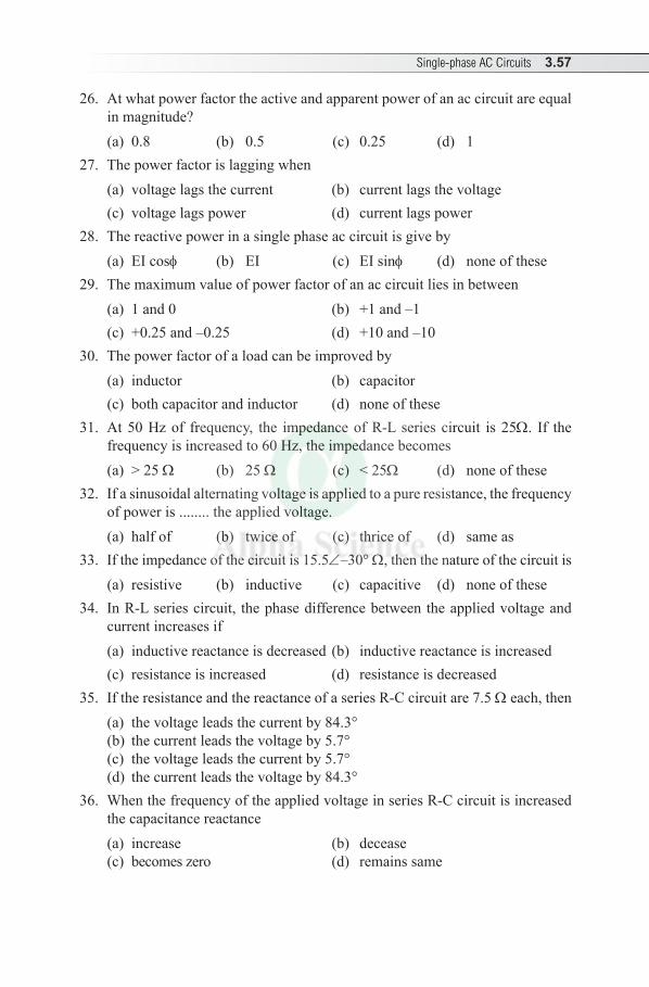
Single-phase AC Circuits 3.57
26. At what power factor the active and apparent power of an ac circuit are equal in magnitude?(a) 0.8 (b) 0.5 (c) 0.25 (d) 1
27. The power factor is lagging when(a) voltage lags the current (b) current lags the voltage (c) voltage lags power (d) current lags power
28. The reactive power in a single phase ac circuit is give by(a) EI cosf (b) EI (c) EI sinf (d) none of these
29. The maximum value of power factor of an ac circuit lies in between (a) 1 and 0 (b) +1 and –1(c) +0.25 and –0.25 (d) +10 and –10
30. The power factor of a load can be improved by(a) inductor (b) capacitor(c) both capacitor and inductor (d) none of these
31. At 50 Hz of frequency, the impedance of R-L series circuit is 25Ω. If the frequency is increased to 60 Hz, the impedance becomes(a) > 25 Ω (b) 25 Ω (c) < 25Ω (d) none of these
32. If a sinusoidal alternating voltage is applied to a pure resistance, the frequency of power is ........ the applied voltage.(a) half of (b) twice of (c) thrice of (d) same as
33. If the impedance of the circuit is 15.5∠–30° Ω, then the nature of the circuit is(a) resistive (b) inductive (c) capacitive (d) none of these
34. In R-L series circuit, the phase difference between the applied voltage and current increases if(a) inductive reactance is decreased (b) inductive reactance is increased(c) resistance is increased (d) resistance is decreased
35. If the resistance and the reactance of a series R-C circuit are 7.5 Ω each, then(a) the voltage leads the current by 84.3° (b) the current leads the voltage by 5.7°(c) the voltage leads the current by 5.7°(d) the current leads the voltage by 84.3°
36. When the frequency of the applied voltage in series R-C circuit is increased the capacitance reactance (a) increase (b) decease(c) becomes zero (d) remains same
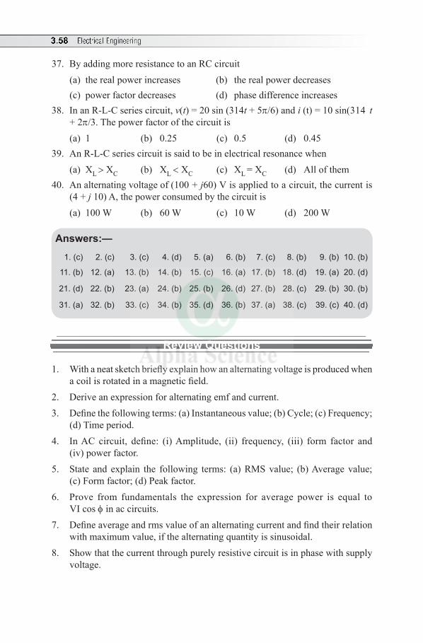
3.58 Electrical Engineering
37. By adding more resistance to an RC circuit(a) the real power increases (b) the real power decreases (c) power factor decreases (d) phase difference increases
38. In an R-L-C series circuit, v(t) = 20 sin (314t + 5p/6) and i (t) = 10 sin (314 t + 2p/3. The power factor of the circuit is(a) 1 (b) 0.25 (c) 0.5 (d) 0.45
39. An R-L-C series circuit is said to be in electrical resonance when(a) XL > XC (b) XL < XC (c) XL = XC (d) All of them
40. An alternating voltage of (100 + j60) V is applied to a circuit, the current is (4 + j 10) A, the power consumed by the circuit is (a) 100 W (b) 60 W (c) 10 W (d) 200 W
Answers:—
1. (c) 2. (c) 3. (c) 4. (d) 5. (a) 6. (b) 7. (c) 8. (b) 9. (b) 10. (b)
11. (b) 12. (a) 13. (b) 14. (b) 15. (c) 16. (a) 17. (b) 18. (d) 19. (a) 20. (d)
21. (d) 22. (b) 23. (a) 24. (b) 25. (b) 26. (d) 27. (b) 28. (c) 29. (b) 30. (b)
31. (a) 32. (b) 33. (c) 34. (b) 35. (d) 36. (b) 37. (a) 38. (c) 39. (c) 40. (d)
Review Questions
1. With a neat sketch briefly explain how an alternating voltage is produced when a coil is rotated in a magnetic field.
2. Derive an expression for alternating emf and current.3. Define the following terms: (a) Instantaneous value; (b) Cycle; (c) Frequency;
(d) Time period. 4. In AC circuit, define: (i) Amplitude, (ii) frequency, (iii) form factor and
(iv) power factor.5. State and explain the following terms: (a) RMS value; (b) Average value;
(c) Form factor; (d) Peak factor.6. Prove from fundamentals the expression for average power is equal to
VI cos f in ac circuits.7. Define average and rms value of an alternating current and find their relation
with maximum value, if the alternating quantity is sinusoidal.8. Show that the current through purely resistive circuit is in phase with supply
voltage.
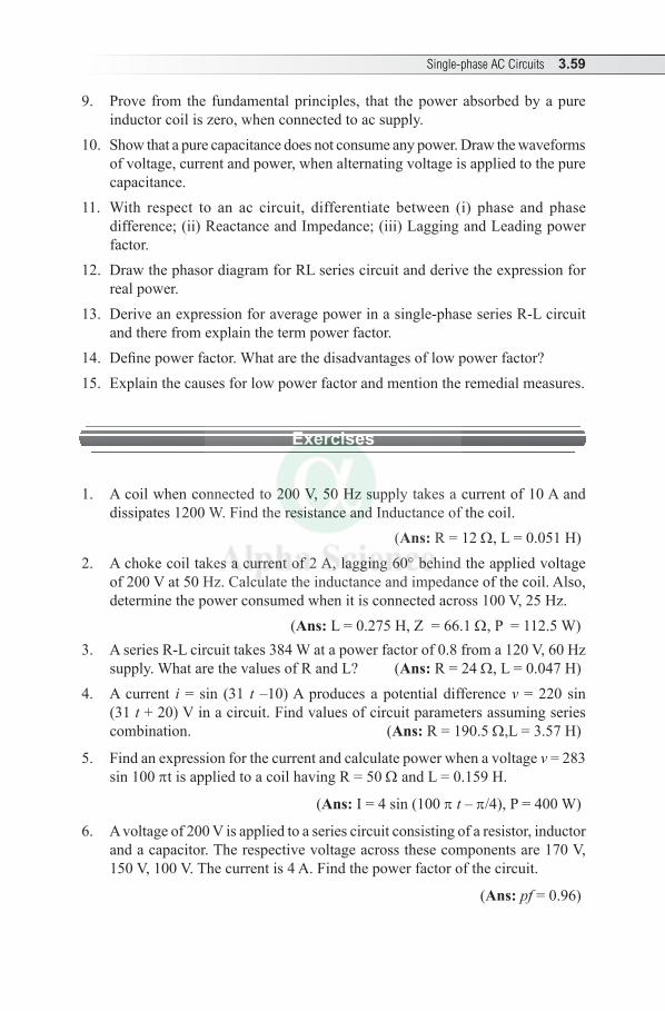
Single-phase AC Circuits 3.59
9. Prove from the fundamental principles, that the power absorbed by a pure inductor coil is zero, when connected to ac supply.
10. Show that a pure capacitance does not consume any power. Draw the waveforms of voltage, current and power, when alternating voltage is applied to the pure capacitance.
11. With respect to an ac circuit, differentiate between (i) phase and phase difference; (ii) Reactance and Impedance; (iii) Lagging and Leading power factor.
12. Draw the phasor diagram for RL series circuit and derive the expression for real power.
13. Derive an expression for average power in a single-phase series R-L circuit and there from explain the term power factor.
14. Define power factor. What are the disadvantages of low power factor?15. Explain the causes for low power factor and mention the remedial measures.
Exercises
1. A coil when connected to 200 V, 50 Hz supply takes a current of 10 A and dissipates 1200 W. Find the resistance and Inductance of the coil.
(Ans: R = 12 Ω, L = 0.051 H) 2. A choke coil takes a current of 2 A, lagging 60° behind the applied voltage
of 200 V at 50 Hz. Calculate the inductance and impedance of the coil. Also, determine the power consumed when it is connected across 100 V, 25 Hz. (Ans: L = 0.275 H, Z = 66.1 Ω, P = 112.5 W)
3. A series R-L circuit takes 384 W at a power factor of 0.8 from a 120 V, 60 Hz supply. What are the values of R and L? (Ans: R = 24 Ω, L = 0.047 H)
4. A current i = sin (31 t –10) A produces a potential difference v = 220 sin (31 t + 20) V in a circuit. Find values of circuit parameters assuming series combination. (Ans: R = 190.5 Ω,L = 3.57 H)
5. Find an expression for the current and calculate power when a voltage v = 283 sin 100 pt is applied to a coil having R = 50 Ω and L = 0.159 H.
(Ans: I = 4 sin (100 p t – p/4), P = 400 W)
6. A voltage of 200 V is applied to a series circuit consisting of a resistor, inductor and a capacitor. The respective voltage across these components are 170 V, 150 V, 100 V. The current is 4 A. Find the power factor of the circuit.
(Ans: pf = 0.96)
3.60 Electrical Engineering
7. A resistance of 5 Ω, an inductance of 10 mH and a capacitor of 200 µF are connected in series and the combination is connected across a 230 V, 50 Hz supply. Calculate the current flowing through the circuit and the power factor. (Ans: I = 16.8 A, pf = 0.365)
8. A coil of resistance 10 Ω and inductance of 0.1 H are connected in series with a condenser of capacitance of 150 µF across 200 V, 50 Hz. Calculate (i) XL (ii) XC (iii) Z and (iv) current.
(Ans: XL = 81.14 Ω; XC = 21.22 Ω; Z = 14.276 Ω; I = 14 A)
9. Two impedances Z1 = (10 + j15) Ω and Z2 = (6 – j 8)Ω are connected in parallel. The total current supplied is 15 A. What is the power taken by each branch? (Ans: P1 = 736.16 W, P2 = 1432.2 W)
10. An alternating voltage of (160 + j 120) V is applied to a circuit and current in circuit is (6 + j8) A. Find (i) the values of circuit elements of circuit (ii) pf of the circuit and (iii) power consumed.
(Ans: R = 19.2 Ω, C = 570 µF, pf = 0.96, P = 1920 W)
11. Two circuits A and B are connected in parallel across 200 V, 50 Hz supply. Circuit A consists of 10 Ω resistance and 0.12 H inductance in series. Circuit B consists of 20 Ω resistance in series with 40 µF capacitor. Calculate (i) current in each branch, (ii) total current and (iii) power factor of the circuit. Draw phasor diagram.
(Ans: I1 = 5.128∠–75.14°A, I2 = 2.437 ∠75.89°A, I = 3.22 ∠–53.64°A, pf = 0.592)
12. A current of average value 18.019 A is flowing in a circuit to which a voltage of peak value 141.42 V is applied. Determine (i) impedance in polar form and (ii) power. Assume voltage lags current by 30°.
(Ans: Z = 5∠-30° Ω and P = 1.732 kW)13. A parallel circuit comprises a resistor of 20 ohm in series with an inductive
reactance of 15 ohm an one branch and a resistor of 30 ohm in series with a capacitive reactance of 20 ohm in other branch. Determine the current and power dissipated in each branch, if the total current drawn by parallel circuit is 10∠–30 amp.
(Ans: I1 = 7.176 A, I2 = 4.97 A, P1 = 1029.9 W and P2 = 741.62 W)14. The circuit diagram shown below is operating at w = 50 rad/sec. Construct
two phasor diagrams one for 3 voltages and other for 3 currents. (Ans: V2 = 2∠90°V, V3 = 2.82∠–45°V, V1 = 2V I2 = 1.414 ∠–45°A and
I3 =1.414 ∠45°A)
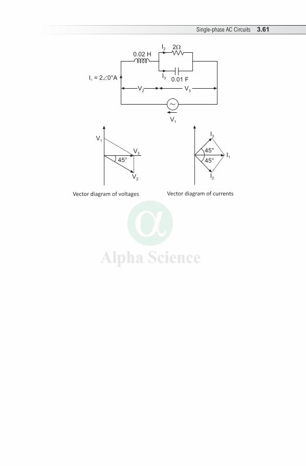
Single-phase AC Circuits 3.61
I2
I3
2
0.01 F
0.02 H
I = 2 0°A1
V2 V3
~V1
V3
V1
45°
V2
Vector diagram of voltages
I1
I3
45°
I2
45°
Vector diagram of currents

3.62 Electrical Engineering
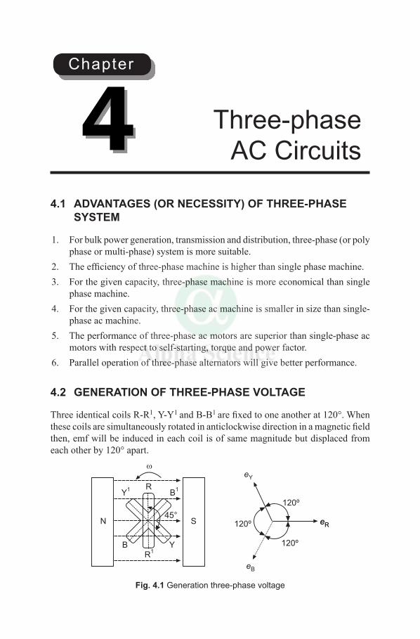
4.1 ADVANTAGES (OR NECESSITY) OF THREE-PHASE SYSTEM
1. For bulk power generation, transmission and distribution, three-phase (or poly phase or multi-phase) system is more suitable.
2. Theefficiencyofthree-phasemachineishigherthansinglephasemachine.3. Forthegivencapacity,three-phasemachineismoreeconomicalthansingle
phasemachine.4. Forthegivencapacity,three-phaseacmachineissmallerinsizethansingle-
phaseacmachine.5. Theperformanceofthree-phaseacmotorsaresuperiorthansingle-phaseac
motorswithrespecttoself-starting,torqueandpowerfactor.6. Paralleloperationofthree-phasealternatorswillgivebetterperformance.
4.2 GENERATION OF THREE-PHASE VOLTAGE
ThreeidenticalcoilsR-R1, Y-Y1 and B-B1
arefixedtooneanotherat120°.Whenthesecoilsaresimultaneouslyrotatedinanticlockwisedirectioninamagneticfieldthen,emfwillbeinducedineachcoilisofsamemagnitudebutdisplacedfromeachotherby120°apart.
120º
120º
120º
eY
eReR
eB
B YR
1
Y1
B1R
45°SN
Fig. 4.1 Generation three-phase voltage
Three-phase AC Circuits4
Chapter
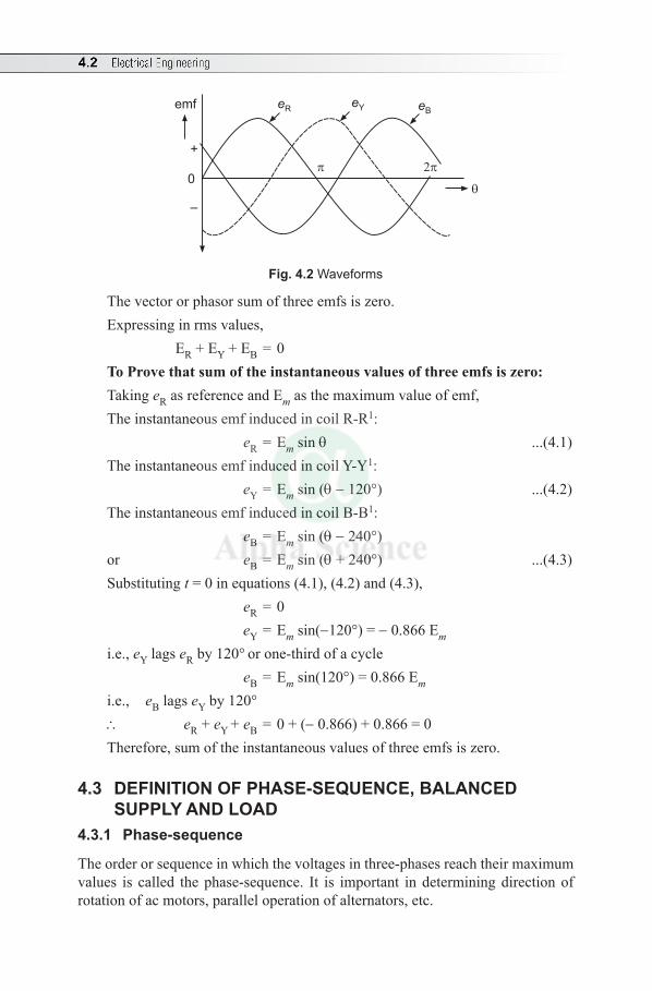
4.2 Electrical Engineering
0
+
–
emf eReY eB
Fig. 4.2 Waveforms
Thevectororphasorsumofthreeemfsiszero.Expressinginrmsvalues, ER + EY + EB=0To Prove that sum of the instantaneous values of three emfs is zero:Taking eRasreferenceandEmasthemaximumvalueofemf,TheinstantaneousemfinducedincoilR-R1: eR = Em sin q ...(4.1)TheinstantaneousemfinducedincoilY-Y1: eY = Em sin (q -120°) ...(4.2)TheinstantaneousemfinducedincoilB-B1: eB = Em sin (q - 240°)or eB = Em sin (q+240°) ...(4.3)Substituting t=0inequations(4.1),(4.2)and(4.3), eR=0 eY = Em sin(-120° ) = -0.866Em i.e., eY lags eRby120°
orone-thirdofacycle eB = Emsin(120°
)=0.866Em i.e., eB lags eYby120°
\ eR + eY + eB=0+(-0.866)+0.866=0Therefore,sumoftheinstantaneousvaluesofthreeemfsiszero.
4.3 DEFINITION OF PHASE-SEQUENCE, BALANCED SUPPLY AND LOAD
4.3.1 Phase-sequence
Theorderorsequenceinwhichthevoltagesinthree-phasesreachtheirmaximumvalues is called thephase-sequence. It is important indeterminingdirectionofrotationofacmotors,paralleloperationofalternators,etc.
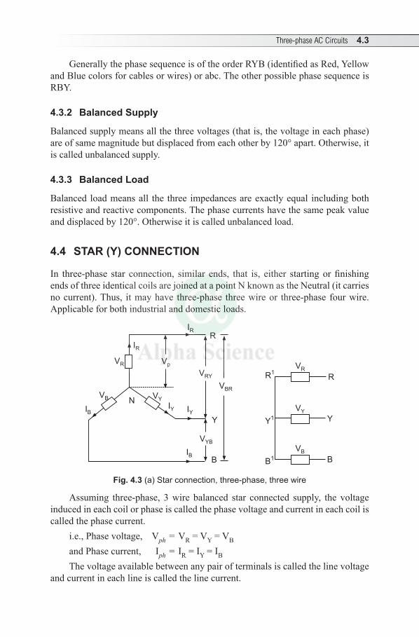
Three-phase AC Circuits 4.3
GenerallythephasesequenceisoftheorderRYB(identifiedasRed,YellowandBluecolorsforcablesorwires)orabc.TheotherpossiblephasesequenceisRBY.
4.3.2 Balanced Supply
Balancedsupplymeansallthethreevoltages(thatis,thevoltageineachphase)areofsamemagnitudebutdisplacedfromeachotherby120°apart.Otherwise,itiscalledunbalancedsupply.
4.3.3 Balanced Load
Balancedloadmeansall the three impedancesareexactlyequal includingbothresistiveandreactivecomponents.Thephasecurrentshavethesamepeakvalueanddisplacedby120°.Otherwiseitiscalledunbalancedload.
4.4 STAR (Y) CONNECTION
In three-phase star connection, similar ends, that is, either startingorfinishingendsofthreeidenticalcoilsarejoinedatapointNknownastheNeutral(itcarriesnocurrent).Thus, itmayhave three-phase threewireor three-phase fourwire.Applicableforbothindustrialanddomesticloads.
R1
Y1
B1
VR
VY
VB
R
Y
B
R
VRY
VR
VBR
Y
VYB
IB
IYIY
VYVB
IB
N
IR
IR
Vp
B
Fig. 4.3 (a) Star connection, three-phase, three wire
Assuming three-phase, 3wire balanced star connected supply, the voltageinducedineachcoilorphaseiscalledthephasevoltageandcurrentineachcoiliscalledthephasecurrent.
i.e., Phase voltage, Vph = VR = VY = VB andPhasecurrent, Iph= IR=IY=IBThevoltageavailablebetweenanypairofterminalsiscalledthelinevoltage
andcurrentineachlineiscalledthelinecurrent.
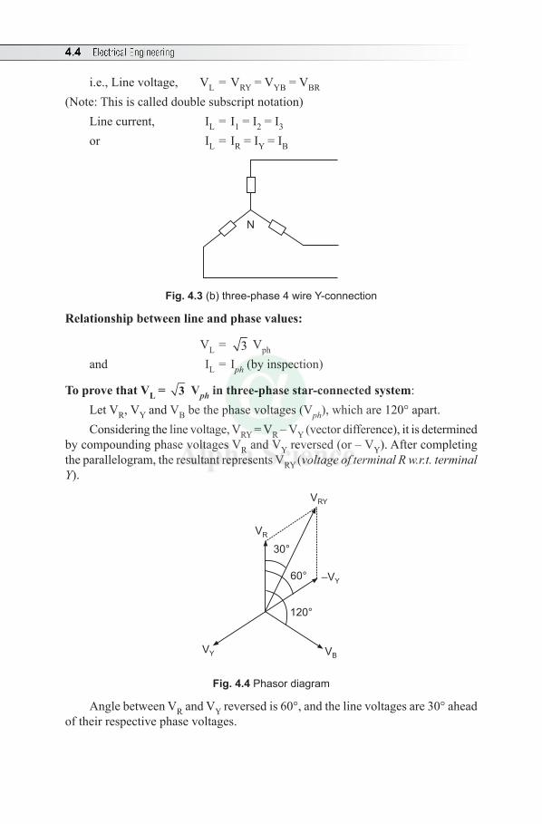
4.4 Electrical Engineering
i.e., Line voltage, VL = VRY = VYB = VBR (Note:Thisiscalleddoublesubscriptnotation)
Linecurrent, IL= I1=I2=I3
or IL= IR=IY=IB
N
Fig. 4.3 (b) three-phase 4 wire Y-connection
Relationship between line and phase values:
VL = 3 Vph
and IL= Iph(byinspection)
To prove that VL = 3 Vph in three-phase star-connected system:Let VR, VY and VB be the phase voltages (Vph),whichare120°apart. Considering the line voltage, VRY = VR – VY(vectordifference),itisdetermined
bycompoundingphasevoltagesVR and VY reversed (or – VY).Aftercompletingthe parallelogram, the resultant represents VRY(voltage of terminal R w.r.t. terminal Y).
120°
60°
30°
–VY
VRY
VR
VBVY
Fig. 4.4 Phasor diagram
Angle between VR and VYreversedis60°,andthelinevoltagesare30°aheadoftheirrespectivephasevoltages.
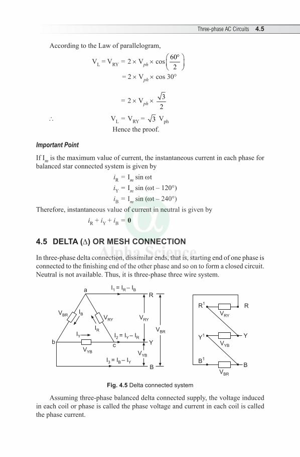
Three-phase AC Circuits 4.5
AccordingtotheLawofparallelogram,
VL = VRY = 2 × Vph ×cos602
°
= 2 × Vph ×cos30°
= 2 × Vph × 32
\ VL = VRY = 3 Vph Hencetheproof.
Important Point
IfImisthemaximumvalueofcurrent,theinstantaneouscurrentineachphaseforbalancedstarconnectedsystemisgivenby
iR= Im sin wt iY= Im sin (wt–120°) iB= Im sin (wt–240°)
Therefore,instantaneousvalueofcurrentinneutralisgivenby iR + iY + iB = 0
4.5 DELTA (D) OR MESH CONNECTION
Inthree-phasedeltaconnection,dissimilarends,thatis,startingendofonephaseisconnectedtothefinishingendoftheotherphaseandsoontoformaclosedcircuit.Neutralisnotavailable.Thus,itisthree-phasethreewiresystem.
R1
Y1
B1
R
Y
B
VRY
VBR
VYB
VBR
VYB
R
Y
B
VRY
VBRIR
a I = I – I1 R B
I = I – I2 Y R
VRY
IB
IY
I = I – I3 B Y
cVYB
b
Fig. 4.5 Delta connected system
Assumingthree-phasebalanceddeltaconnectedsupply,thevoltageinducedineachcoilorphaseiscalledthephasevoltageandcurrentineachcoiliscalledthephasecurrent.
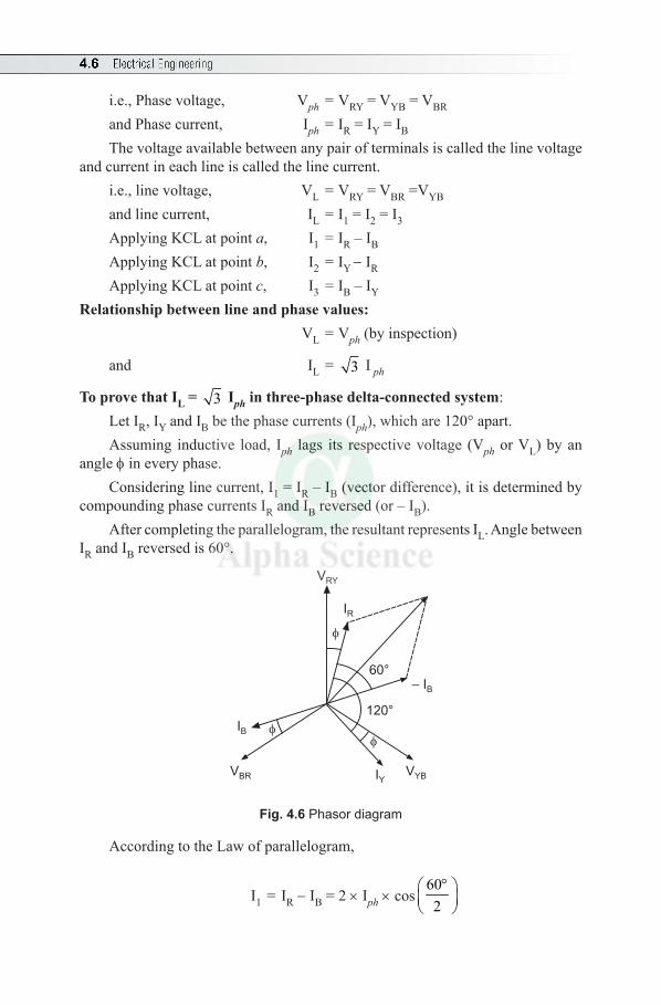
4.6 Electrical Engineering
i.e., Phase voltage, Vph = VRY = VYB = VBR andPhasecurrent, Iph =IR=IY=IBThevoltageavailablebetweenanypairofterminalsiscalledthelinevoltage
andcurrentineachlineiscalledthelinecurrent.i.e., line voltage, VL = VRY = VBR =VYB andlinecurrent, IL =I1=I2=I3Applying KCL at point a, I1 =IR–IBApplying KCL at point b, I2 =IY -IRApplying KCL at point c, I3 =IB–IY
Relationship between line and phase values: VL = Vph(byinspection)
and IL = 3 I ph
To prove that IL = 3 Iph in three-phase delta-connected system:LetIR,IYandIBbethephasecurrents(Iph),whichare120°apart.Assuming inductive load, Iph lags its respectivevoltage (Vph or VL) by an
angle f in every phase. Consideringlinecurrent,I1=IR–IB(vectordifference),itisdeterminedby
compoundingphasecurrentsIRandIBreversed(or–IB). Aftercompletingtheparallelogram,theresultantrepresentsIL. Angle between
IRandIBreversedis60°.
IR
– IB
120°
60°
IY
IB
VYBVBR
VRY
Fig. 4.6 Phasor diagram
AccordingtotheLawofparallelogram,
I1= IR -IB = 2 ×Iph ×cos602
°
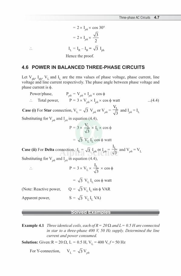
Three-phase AC Circuits 4.7
= 2 ×Iph ×cos30°
= 2 ×Iph × 32
\ IL = IR–IB = 3 Iph
Hencetheproof.
4.6 POWER IN BALANCED THREE-PHASE CIRCUITS
Let Vph, Iph, VL and IL are the rmsvaluesofphasevoltage,phasecurrent, linevoltageandlinecurrentrespectively.Thephaseanglebetweenphasevoltageandphasecurrentisf.
Power/phase, Pph = Vph ×Iph ×cosf \ Total power, P = 3 × Vph ×Iph ×cosf watt ...(4.4)
Case (i) For Starconnection,VL = 3 Vph or Vph = LV3
andIph=ILSubstituting for VphandIph inequation(4.4),
P = 3 × LV3
×IL ×cosf
= 3 VLILcosf watt
Case (ii) For Deltaconnection,IL = 3 Iph orIph = LI3
and Vph = VL
Substituting for VphandIph inequation (4.4),
\ P = 3 × VL × LI3
×cosf
= 3 VLIL cos f watt
(Note:Reactivepower, Q= 3 VL IL sin fVAR
Apparent power, S = 3 VL IL VA)
Solved Examples
Example 4.1 Three identical coils, each of R = 20 W and L = 0.5 H are connected in star to a three-phase 400 V, 50 Hz supply. Determined the line current and power consumed.
Solution:Given:R=20W,L=0.5H,VL=400V,f=50Hz
ForY-connection, VL = 3 Vph
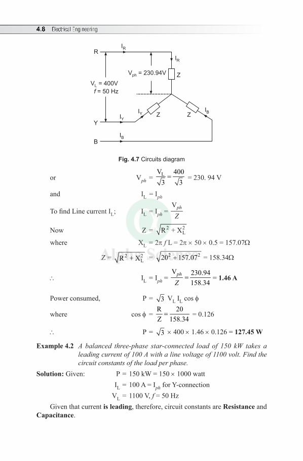
4.8 Electrical Engineering
Z ZIB
IYIY
IB
Y
B
RIR
V = 230.94Vph
V = 400V
= 50 HzL
f
IR
Z
Fig. 4.7 Circuits diagram
or Vph = LV 4003 3
= =230.94V
and IL =Iph
TofindLinecurrentIL; IL =Iph = Vph
Z
Now Z= 2 2LR + X
where XL = 2p f L = 2p ×50×0.5=157.07W
Z= 2 2LR + X = 2 220 157.07+ =158.34W
\ IL =Iph = V 230.94
158.34ph
Z= = 1.46 A
Powerconsumed, P = 3 V LILcosf
where cosf = R 20Z 158.34
= =0.126
\ P = 3 ×400× 1.46 ×0.126=127.45 W
Example 4.2 A balanced three-phase star-connected load of 150 kW takes a leading current of 100 A with a line voltage of 1100 volt. Find the circuit constants of the load per phase.
Solution: Given: P=150kW=150×1000watt IL=100A=IphforY-connection VL=1100V,f=50HzGiventhatcurrentis leading,therefore,circuitconstantsareResistance and
Capacitance.
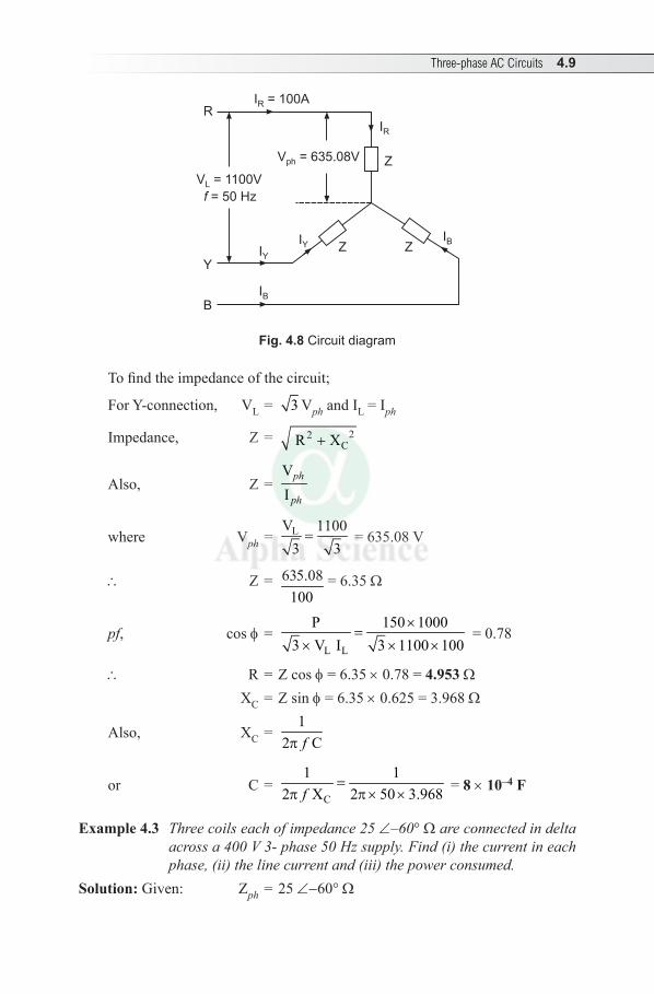
Three-phase AC Circuits 4.9
Z ZIB
IYIY
IB
Y
B
RI = 100AR
V = 635.08Vph
V = 1100V
= 50 HzL
f
IR
Z
Fig. 4.8 Circuit diagram
Tofindtheimpedanceofthecircuit;
ForY-connection, VL = 3 VphandIL=Iph
Impedance, Z = 22CR X+
Also, Z=VI
ph
ph
where Vph = LV 11003 3
= =635.08V
\ Z= 635.08100
= 6.35 W
pf, cosf = L L
P 150 10003 V I 3 1100 100
×=
× × ×=0.78
\ R=Z cosf = 6.35 ×0.78=4.953 W XC=Zsinf = 6.35 ×0.625=3.968W
Also, XC = 1
2 Cfp
or C = C
1 12 X 2 50 3.968f
=p p × × = 8 × 10⁻⁴ F
Example 4.3 Three coils each of impedance 25 ∠–60° W are connected in delta across a 400 V 3- phase 50 Hz supply. Find (i) the current in each phase, (ii) the line current and (iii) the power consumed.
Solution: Given: Zph = 25 ∠-60°W
IBIB IBIB
IBIB
IBIBIBIB
IBIB
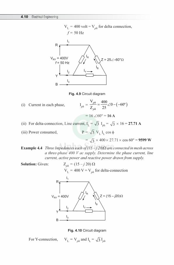
4.10 Electrical Engineering
VL=400volt=Vphfordeltaconnection, f=50Hz
Z = 25 –60°
IY
IB
IR
Y
B
I1
I2
I3
R
V = 400V
= 50 HzRY
f
Fig. 4.9 Circuit diagram
(i) Currentineachphase, Iph = ( )V 400 0 60Z 25
= ∠ - - °ph
ph
= 16 ∠60°=16 A
(ii) Fordelta-connection,Linecurrent,IL = 3 Iph = 3 × 16 = 27.71 A
(iii)Powerconsumed, P= 3 VLILcosf
= 3 ×400×27.71×cos60°=9599 W
Example 4.4 Three Impedances each of (15 – j 20)W are connected in mesh across a three-phase 400 V ac supply. Determine the phase current, line current, active power and reactive power drawn from supply.
Solution:Given: Zph = (15 – j20)W VL=400V=Vphfordelta-connection
Z = (15 – 20j
IY
IB
IR
Y
B
I1
I2
I3
R
V = 400VRY
Fig. 4.10 Circuit diagram
ForY-connection, VL = Vph andIL = 3 Iph
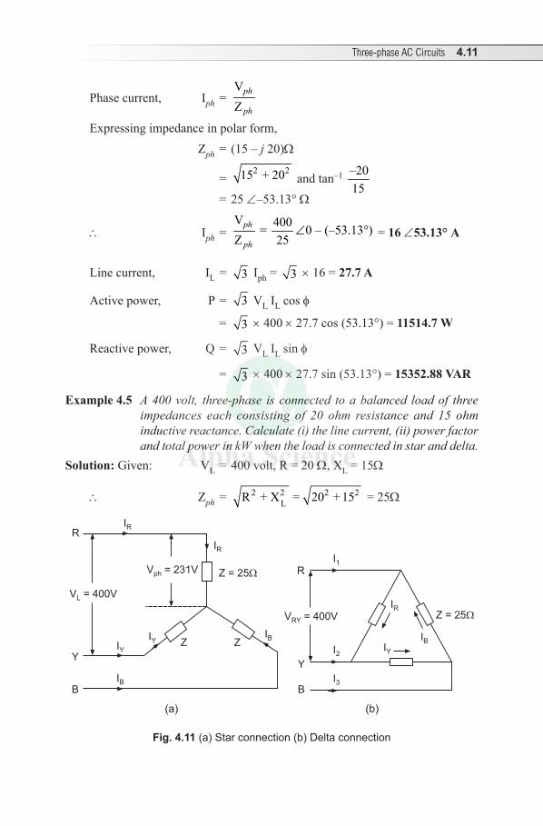
Three-phase AC Circuits 4.11
Phasecurrent, Iph = VZ
ph
ph
Expressingimpedance in polar form, Zph = (15 – j 20)W
= 2 215 + 20 and tan–1 –20
15
= 25 ∠–53.13°W
\ Iph = V 400= 0–(–53.13°)Z 25
∠ph
ph = 16 ∠53.13° A
Linecurrent, IL = 3 Iph = 3 × 16 = 27.7 A
Activepower, P= 3 VLILcosf
= 3 ×400×27.7cos(53.13°)=11514.7 W
Reactivepower, Q = 3 VLIL sin f
= 3 ×400×27.7sin(53.13°)=15352.88 VAR
Example 4.5 A 400 volt, three-phase is connected to a balanced load of three impedances each consisting of 20 ohm resistance and 15 ohm inductive reactance. Calculate (i) the line current, (ii) power factor and total power in kW when the load is connected in star and delta.
Solution: Given: VL=400volt,R=20W,XL = 15W
\ Zph = 2 2 2 2LR + X = 20 +15 = 25W
Z ZIB
IYIY
IB
Y
B
RIR
V = 231Vph
V = 400VL
IR
Z = 25
Z = 25
IY
IB
IR
Y
B
I1
I2
I3
R
V = 400VRY
(a) (b)
Fig. 4.11 (a) Star connection (b) Delta connection
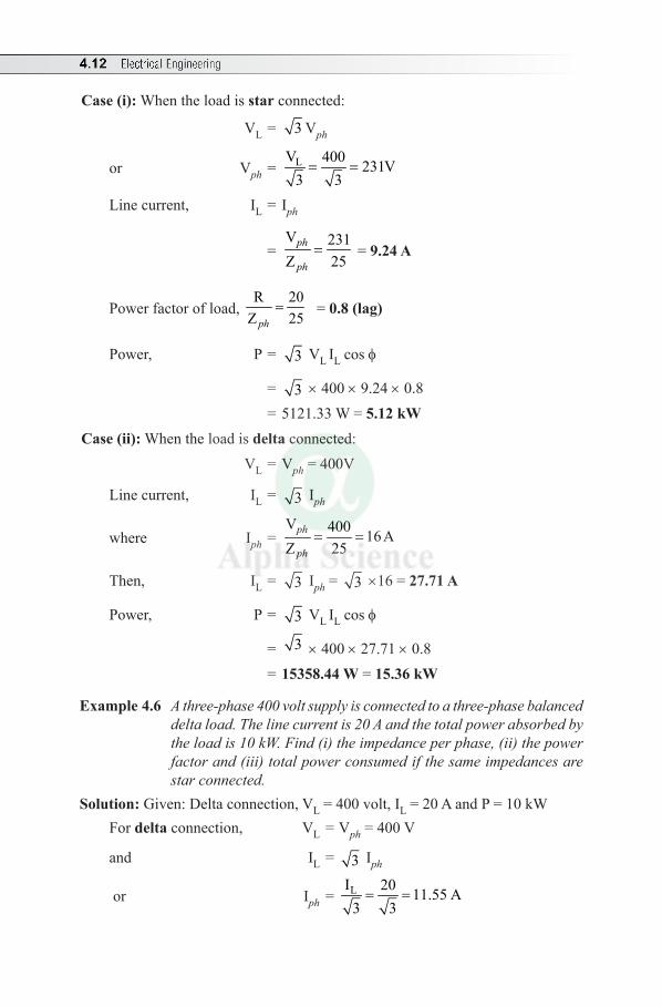
4.12 Electrical Engineering
Case (i):Whentheloadisstarconnected:
VL = 3 Vph
or Vph = LV 400 231V3 3
= =
Linecurrent, IL = Iph
= V 231Z 25
ph
ph= = 9.24 A
Powerfactorofload,R 20Z 25ph
= = 0.8 (lag)
Power, P = 3 VL ILcosf
= 3 ×400×9.24×0.8 =5121.33W= 5.12 kW
Case (ii):Whentheloadisdeltaconnected: VL = Vph=400V
Linecurrent, IL = 3 Iph
where Iph = V 400 16AZ 25
= =ph
ph
Then, IL = 3 Iph = 3 ×16 = 27.71 A
Power, P = 3 VL ILcosf
= 3 ×400×27.71×0.8
= 15358.44 W = 15.36 kW
Example 4.6 A three-phase 400 volt supply is connected to a three-phase balanced delta load. The line current is 20 A and the total power absorbed by the load is 10 kW. Find (i) the impedance per phase, (ii) the power factor and (iii) total power consumed if the same impedances are star connected.
Solution:Given:Deltaconnection,VL=400volt,IL=20AandP=10kWFor deltaconnection, VL = Vph=400V
and IL = 3 Iph
or Iph = LI 20 11.55 A3 3
= =
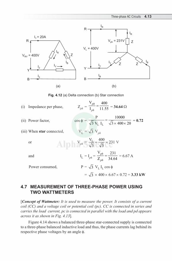
Three-phase AC Circuits 4.13
Z ZIB
IYIY
IB
Y
B
RIR
V = 231Vph
V = 400VL
IR
Z
Z
IY
IB
IR
Y
B
I = 20A1
I2
I3
R
V = 400VRY
(a) (b)
Fig. 4.12 (a) Delta connection (b) Star connection
(i) Impedanceperphase, Zph = V 400I 11.55
=ph
ph = 34.64 W
(ii) Powerfactor, cosf = L L
P 100003 V I 3 400 20
=× ×
= 0.72
(iii)Whenstarconnected, VL = 3 Vph
or Vph = LV 400 231 3 3
= = V
and IL =Iph = V 231Z 34.64
=ph
ph=6.67A
Powerconsumed, P= 3 VLILcosf
= 3 ×400×6.67×0.72=3.33 kW
4.7 MEASUREMENT OF THREE-PHASE POWER USING TWO WATTMETERS
[Concept of Wattmeter: It is used to measure the power. It consists of a current coil (CC) and a voltage coil or potential coil (pc). CC is connected in series and carries the load current, pc is connected in parallel with the load and pd appears across it as shown in Fig. 4.13].
Figure4.14showsabalancedthree-phasestar-connectedsupplyisconnectedtoathree-phasebalancedinductiveloadandthus,thephasecurrentslagbehinditsrespectivephasevoltagesbyananglef.
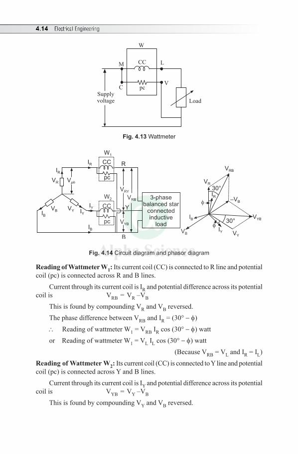
4.14 Electrical Engineering
W
CC
pc
Load
M L
CV
Supplyvoltage
Fig. 4.13 Wattmeter
3-phasebalanced star
connectedinductive
load
Vph
VR
VRY
VYB
VRB
IR
IR
IB
IB
IY
IYVB VYY
CC
CC
pc
pc
W1
W2
R
B
–VB
VYB
VY
IYVB
IB
IR
30°
VRB
VR
30°
Fig. 4.14 Circuit diagram and phasor diagram
Reading of Wattmeter W1:Itscurrentcoil(CC)isconnectedtoRlineandpotentialcoil(pc)isconnectedacrossRandBlines.
CurrentthroughitscurrentcoilisIRandpotentialdifferenceacrossitspotentialcoilis VRB = VR –VB
ThisisfoundbycompoundingVR and VB reversed.ThephasedifferencebetweenVRBandIR=(30° - f)\ ReadingofwattmeterW1 = VRBIRcos(30° - f) wattor ReadingofwattmeterW1 = VLILcos(30°- f) watt (BecauseVRB = VLandIR=IL)
Reading of Wattmeter W2: Itscurrentcoil(CC)isconnectedtoYlineandpotentialcoil(pc)isconnectedacrossYandBlines.
CurrentthroughitscurrentcoilisIYandpotentialdifferenceacrossitspotentialcoilis VYB = VY –VB
ThisisfoundbycompoundingVY and VB reversed.
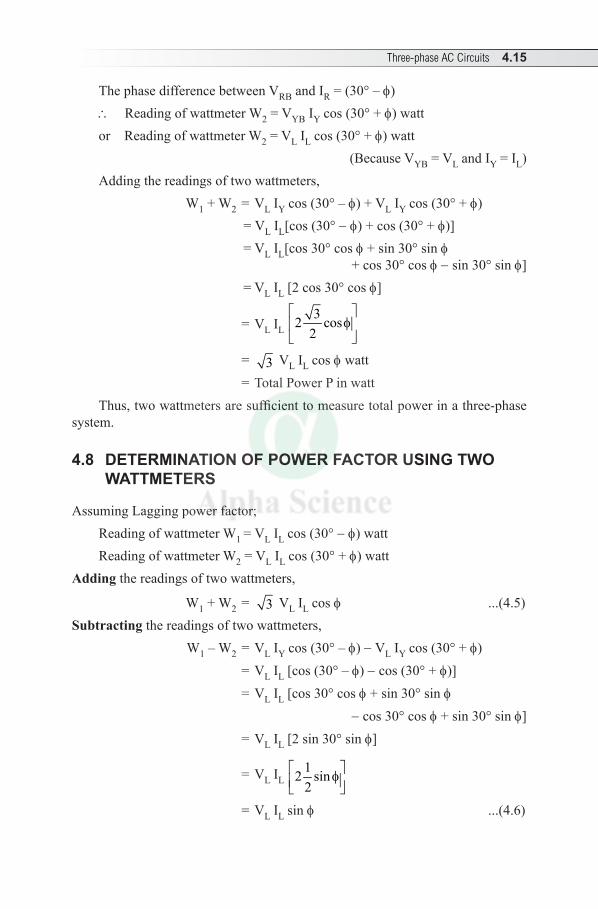
Three-phase AC Circuits 4.15
ThephasedifferencebetweenVRBandIR=(30° – f)\ ReadingofwattmeterW2 = VYBIYcos(30° + f) wattor ReadingofwattmeterW2 = VLILcos(30° + f) watt (Because VYB = VLandIY=IL)Adding the readings of two wattmeters, W1+W2 = VLIYcos(30° – f) + VLIYcos(30° + f) = VLIL[cos(30° - f)+cos(30° + f)] = VLIL[cos30° cosf+sin30° sin f +cos30°cosf -sin30°sinf] = VLIL[2cos30°cosf]
= VLIL 32 cos
2
f
= 3 VLILcosf watt = Total Power P in watt Thus,twowattmetersaresufficienttomeasuretotalpowerinathree-phase
system.
4.8 DETERMINATION OF POWER FACTOR USING TWO WATTMETERS
AssumingLaggingpowerfactor;ReadingofwattmeterW1 = VLILcos(30°- f) watt ReadingofwattmeterW2 = VLILcos(30°+f) watt
Adding the readings of two wattmeters,
W1+W2 = 3 VLILcosf ...(4.5)Subtracting the readings of two wattmeters,
W1–W2 = VLIYcos(30°–f) - VLIYcos(30°+f) = VLIL[cos(30°– f) -cos(30°+ f)] = VLIL[cos30°cosf+sin30°sin f
-cos30°cosf+sin30°sin f] = VLIL[2sin30°sinf]
= VLIL 12 sin2
f
= VLIL sin f ...(4.6)
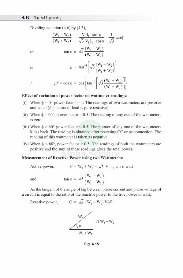
4.16 Electrical Engineering
Dividingequation(4.6)by(4.5),
1 2
1 2
(W – W )(W W )+
= L L
L L
V I sin 1 tan3V I cos 3
f= f
f
or tan f = 1 2
1 2
(W – W )3(W W )+
or f = –1 1 2
1 2
(W – W )tan 3(W W )
+
\ pf=cosf = –1 1 2
1 2
(W – W )cos tan 3(W W )
+
Effect of variation of power factor on wattmeter readings:(i) Whenf=0°, powerfactor=1:Thereadingsoftwowattmetersarepositive
andequal(thenatureofloadispureresistive).(ii) Whenf=60°,powerfactor=0.5:Thereadingofanyoneofthewattmeters
iszero.(iii)Whenf>60°, powerfactor<0.5:Thepointerofanyoneofthewattmeters
kicksback.ThereadingisobtainedafterreversingCCorpcconnection.Thereading of this wattmeter is taken as negative.
(iv)Whenf<60°,powerfactor>0.5:Thereadingsofboththewattmetersarepositive and the sum of these readings gives the total power.
Measurement of Reactive Power using two Wattmeters:
Activepower, P=W1+W2 = 3 VLILcosf watt
and tan f = ( )( )
1 2
1 2
W – W3
W +W
As the tangent of theangleoflagbetweenphasecurrentandphasevoltageofacircuitisequaltotheratioofthereactivepowertothetruepowerinwatt;
Reactivepower, Q= 3 (W1–W2)VAR
VA
W + W1 2
3 W – W1 2
Fig. 4.15
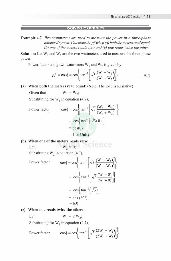
Three-phase AC Circuits 4.17
Solved Examples
Example 4.7 Two wattmeters are used to measure the power in a three-phase balanced system. Calculate the pf when (a) both the meters read equal, (b) one of the meters reads zero and (c) one reads twice the other.
Solution:LetW1andW2 are the two wattmeters used to measure the three-phase power.
PowerfactorusingtwowattmetersW1andW2 is given by
–1 1 2
1 2
(W W )cos cos tan 3(W W )
pf - = f = +
...(4.7)
(a) When both the meters read equal:(Note:TheloadisResistive)Giventhat W1=W2; SubstitutingforW1inequation(4.7),
Powerfactor, –1 2 2
2 2
(W W )cos cos tan 3(W W )
- f = +
= ( ) –1cos tan 3 0
=cos(0) = 1 or Unity
(b) When one of the meters reads zero:Let, W2=0;SubstitutingW2inequation(4.7),
Powerfactor, –1 1 2
1 2
(W W )cos cos tan 3(W W )
- f = +
= –1 1
1
(W 0)cos tan 3(W 0)
- +
= ( )–1cos tan 3
=cos(60°) = 0.5
(c) When one reads twice the other:Let W1=2W2; SubstitutingforW1inequation(4.7),
Powerfactor, –1 1 2
1 2
(2W W )cos cos tan 3(2W W )
- f = +
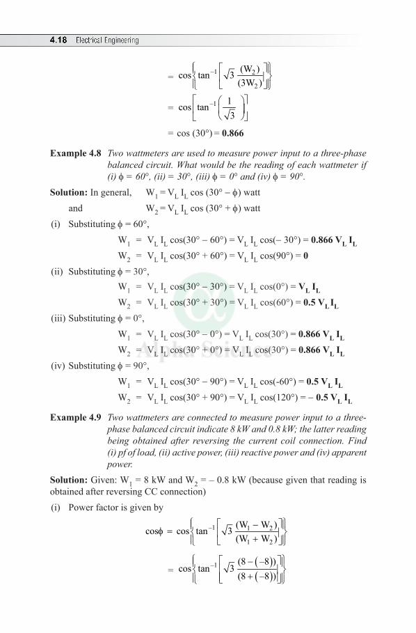
4.18 Electrical Engineering
= –1 2
2
(W )cos tan 3(3W )
= –1 1cos tan3
= cos(30°) = 0.866
Example 4.8 Two wattmeters are used to measure power input to a three-phase balanced circuit. What would be the reading of each wattmeter if (i) f = 60°, (ii) = 30°, (iii) f = 0° and (iv) f = 90°.
Solution: Ingeneral, W1 = VLILcos(30°- f) watt and W2 = VLILcos(30°+f) watt
(i) Substituting f=60°, W1 = VLILcos(30°-60°)=VLILcos(-30°)=0.866 VL IL W2 = VLILcos(30°+60°)=VLILcos(90°)=0
(ii) Substituting f=30°, W1 = VLILcos(30°-30°)=VLILcos(0°)=VL IL W2 = VLILcos(30°+30°)=VLILcos(60°)=0.5 VL IL
(iii) Substituting f=0°, W1 = VLILcos(30°-0°)=VLILcos(30°)=0.866 VL IL W2 = VLILcos(30°+0°)=VLILcos(30°)=0.866 VL IL
(iv) Substituting f=90°, W1 = VLILcos(30°-90°)=VLILcos(-60°)=0.5 VL IL W2 = VLILcos(30°+90°)=VLILcos(120°)=- 0.5 VL IL
Example 4.9 Two wattmeters are connected to measure power input to a three-phase balanced circuit indicate 8 kW and 0.8 kW; the latter reading being obtained after reversing the current coil connection. Find (i) pf of load, (ii) active power, (iii) reactive power and (iv) apparent power.
Solution:Given:W1=8kWandW2=–0.8kW(becausegiventhatreadingisobtainedafterreversingCCconnection)(i) Powerfactorisgivenby
–1 1 2
1 2
(W W )cos cos tan 3(W W )
- f = +
= ( )( )
–1 (8 –8 )cos tan 3
(8 –8 )
-
+
Three-phase AC Circuits 4.19
= ( )–1 8.8
cos tan 3(7.2)
= cos(64.71)=0.427 (ii) Activepower, P=W1+W2
=8+(-0.8)=7.2 kW
(iii)Reactivepower, Q= 3 (W1 - W2)
= 3 ×[8–(-0.8)]=15.24 kVAR
(iv) Apparent power, S = kW 7.2cos 0.427
=f = 16.86 kVA
Example 4.10 Each of two wattmeters connected to measure the input to a three-phase reads 10 kW on a balanced load when the pf is unity. What does each instrument reads when the pf falls to (i) 0.866 lag and (ii) 0.5 lag. The total three-phase power remains unchanged.
Solution:Given: W1=W2=10kW Whenpfisunity, cosf = 1; f=0;hence,tanf=0Therefore, totalpower=W1+W2 =10kW+10kW=20kW ...(4.8)
(i) Whenpf, cosf=0.866 =cos–1(0.866)=30° Therefore, tan f= tan(30°)=0.577
Also, tan f = 1 2
1 2
(W W )3(W W )
-+
or 0.577= 1 2(W W )320-
or W1–W2 =6.66 ...(4.9)Solvingequations(4.8)and(4.9), W1+W2=20 W1–W2 = 6.66 2W1 = 26.66 or W1 = 13.33 kW SubstitutingforW1inequation(4.4); 13.33+W2=20 or W2 = 6.67 kW
(ii) Whenpf, cosf=0.5 or f=60°
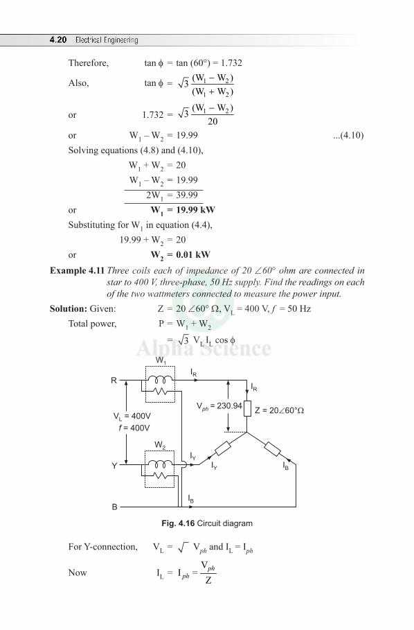
4.20 Electrical Engineering
Therefore, tan f= tan(60°)=1.732
Also, tan f = 1 2
1 2
(W W )3(W W )
-+
or 1.732= 1 2(W W )320-
or W1–W2 =19.99 ...(4.10)Solvingequations(4.8)and(4.10), W1+W2=20 W1–W2=19.99 2W1=39.99or W1 = 19.99 kWSubstitutingforW1inequation(4.4), 19.99+W2=20or W2 = 0.01 kW
Example 4.11 Three coils each of impedance of 20 ∠60° ohm are connected in star to 400 V, three-phase, 50 Hz supply. Find the readings on each of the two wattmeters connected to measure the power input.
Solution:Given: Z=20∠60°W, VL=400V,f=50HzTotalpower, P=W1+W2
= 3 VL ILcosf
V 230.94ph
=Z = 20 60°
V = 400VL
= 400Vf
IR
IR
IB
IB
IY
IYY
W1
W2
R
B
Fig. 4.16 Circuit diagram
ForY-connection, VL = Vph andIL=Iph
Now IL = V
I =Zph
ph
Three-phase AC Circuits 4.21
V ph = LV 400 230.94 V3 3
= =
\ LV 230.94I I 0 60 11.547 – 60 AZ 20ph
ph= = = ∠ - ° = ∠ °
P=W1 +W2
= 3 ×400×11.547×cos(60°)or W1+W2=4000watt ...(4.11)
Now tanf = 1 2
1 2
(W W )3(W W )
-+
where tan(60°)=1.732
\ 1.732=( )1 2W W
34000
-
or W1–W2=4000watt ...(4.12)Solvingequations(4.11)and(4.12), W1 = 4000 watt and W2 = 0
Example 4.12 A three-phase Y connected supply with a phase voltage of 230V is supplying a balanced delta load. The load draws 15 kW at 0.8 pf lagging. Find the line current and the current in each phase of the load. What is load impedance per phase?
Solution:Given:Yconnectedsupply,Vph=230V,P=15kW,pf =0.8lagging
Forstarconnectedsupply, VL = 3 Vph = 3 ×230=400V
Whentheloadisconnectedindelta,
P = 3 VLILcosf
or IL = 3
L
P 15 103 V cos 3 400 0.8
×=
f × × = 27.06 A
Iph = LI 27.063 3
= = 15.625 A
\ Loadimpedanceperphase,Zph = V 400I 15.625
=ph
ph= 25.6 W
Example 4.13 The power input to a 2000 V, 50 Hz, three-phase motor running on full load is measured by two wattmeters which indicate 300 kW and 100 kW respectively. Calculate (i) the input, (ii) the power factor and (iii) the line current.
4.22 Electrical Engineering
Solution: Given: InputVoltage= VL =2000V,f =50Hz W1 =300kWandW2=100kW
(i) Input, P=W1+W2 =300+100=400 kW(ii) Powerfactor, pf=cosf
where f = tan–1 1 2
1 2
3(W W )W W
-+
= tan–1 3(300 100)300 100
-+
= tan–1(0.866)=40.89°
\ pf=cos(40.89°)=0.755(iii)Linecurrent;
IL = L
P3V cosf
(becauseP= 3 VLILcosf)
= 400 1000
3 2000 0.755×
× × = 152.94 A
Multiple Choice Questions
Choose the Correct Answer
1. Athree-phaseequipmenthasasize.......ofasingle-phaseequipmentforsamecapacity(a) bigger than (b) same as(c) smallerthan (d) noneofthese
2. The voltage VAB=50∠30°volt.ThenVBA is ....... volt.(a) 50∠–180° (b) 50∠–150° (c) 50∠–30° (d) 50∠–210°
3. Electricaldisplacementbetweendifferentphasesinasix-phasesystemis(a) 60° (b) 120° (c) 240° (d) noneofthese
4. ThephasesequenceRBYdenotesthat(a) emfofphase-Blagsthatofphase-Rby120°(b) emfofphase-Bleadsthatofphase-Rby120°(c) both(a)and(b)arecorrect(d) none of these
5. Theresistancemeasuredbetweenanytwoterminalsofabalancedthree-phasestarconnectedloadis2R.Theresistanceofeachphasewillbe.......(a) R (b) 2R (c) 4R (d) 6R
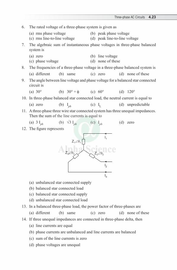
Three-phase AC Circuits 4.23
6. The rated voltage of a three-phase system is given as(a) rms phase voltage (b) peak phase voltage (c) rmsline-to-linevoltage (d) peakline-to-linevoltage
7. Thealgebraic sumof instantaneousphasevoltages in three-phasebalancedsystem is(a) zero (b) linevoltage(c) phasevoltage (d) noneofthese
8. Thefrequenciesofathree-phasevoltageinathree-phasebalancedsystemis(a) different (b) same (c) zero (d) noneofthese
9. Theanglebetweenlinevoltageandphasevoltageforabalancedstarconnectedcircuitis(a) 30° (b) 30°+f (c) 60° (d) 120°
10. Inthree-phasebalancedstarconnectedload,theneutralcurrentisequalto(a) zero (b) Iph (c) IL (d) unpredictable
11. Athree-phasethreewirestarconnectedsystemhasthreeunequalimpedances.Thenthesumofthelinecurrentsisequalto(a) 3Iph (b) √3Iph (c) Iph (d) zero
12. Thefigurerepresents
I1
I2
I3
Z3 3
Z1 1
Z2 2
(a) unbalancedstarconnectedsupply(b) balancedstarconnectedload(c) balancedstarconnectedsupply(d) unbalancedstarconnectedload
13. Inabalancedthree-phaseload,thepowerfactorofthree-phasesare(a) different (b) same (c) zero (d) noneofthese
14. Ifthreeunequalimpedancesareconnectedinthree-phasedelta,then(a) linecurrentsareequal(b) phasecurrentsareunbalancedandlinecurrentsarebalanced(c) sumofthelinecurrentsiszero
(d) phasevoltagesareunequal
4.24 Electrical Engineering
15. Instarconnection,therelationbetweenlineandphasecurrentis(a) IL<Iph (b) IL = √3Iph (c) IL>Iph (d) IL=Iph
16. Inabalanceddeltaconnectedload,theresistancebetweenanytwoterminalsis20ohm.Then,theresistanceofaneachphasewillbe.......ohm.(a) 10 (b) 20 (c) 30 (d) 60
17. Ina3fsystem, if the instantaneousvoltagephaseRandYare+60Vand –40Vrespectively,theninstantaneousvoltageofphaseBis(a) –20V (b) 40V (c) 120V (d) noneoftheabove
18. Inathree-phasebalanceddeltaconnectedsystem,therelationbetweenlinevoltage VL and phase voltage Vph is .......(a) VL = Vph/√3 (b) VL = √3 Vph (c) VL = Vph (d) none of these
19. Thepowerconsumedbyathree-phasestarconnectedloadisgivenby(a) VphIph cosf (b) √3 VphIph cosf (c) 3VLILcosf (d) √3 VLILcosf
20. Thesumofthetwowattmetersreadingsinathree-phasebalancedsystemis(a) VphIph cosf (b) 3 VLILcosf(c) √3 VLILcosf (d) none of these
21. Thetotalpowerconsumedbyathree-phasebalancedloadisgivenby(a) W1 –W2 (b) (W1+W2)/2 (c) √3(W1–W2) (d) none of thesewhereW1andW2 are wattmeter readings.
22. W1andW2 are the readings of two wattmeters used to measure power of a three-phasebalancedload.Theactivepowerdrawnbytheloadis(a) W1 +W2 (b) W1 –W2 (c) √3(W1+W2) (d) √3(W1–W2)
23. Intwowattmetermethodofpowermeasurementtheloadisresistive,ifthewattmetersreadingsareW1andW2 then (a) W1>W2 (b) W1<W2
(c) W1=W2 (d) W1 =0andW2=024. Whentwowattmetersusedtomeasureathree-phasepower,giveequalreadings,
thenthepowerfactorofthecircuitis.......(a) 0.5 (b) 0 (c) 0.866 (d) 1
25. Inathree-phasebalancedsupplysystem,thesumoftheinstantaneousvaluesof three voltages at any instant is .......(a) maximum (b) zero (c) minimum (d) noneofthese
26. Inmeasurement of three-phase power using twowattmeters, if oneof thewattmetersreadszero,thenthepowerfactorofloadis.......(a) zero (b) 0.5 (c) 0.8 (d) 1
Three-phase AC Circuits 4.25
27. Inmeasurement of three-phase power using twowattmeters, if oneof thewattmetersreadsnegativevalue,thenthepowerfactorofthecircuitis(a) 0.5 (b) >0.5 (c) <0.5 (d) noneofthese
28. Inmeasurementofthree-phasepowerusingtwowattmeters,thewattmetersindicateequalandoppositereadingswhentheloadpowerfactorangleis.......degrees lagging.(a) 60° (b) 0° (c) 30° (d) 90°
29. Athree-phasestarconnectedloadconsumesPwattofpowerfroma400Vsupply.Ifthebalancedloadisconnectedindeltaacrossthatsamesupply,thenpowerconsumptionis(a) 3 P (b) √3P (c) P/3 (d) P
30. In,three-phasesystem,powerequation√3VIcosf, f is the angle between (a) VL andIL (b) VLandIph (c) Vph andIL (d) Vph and Iph
Answers:—1. (c) 2. (b) 3. (a) 4. (a) 5. (a) 6. (c) 7. (a) 8. (b) 9. (d) 10. (a)
11. (d) 12. (d) 13. (b) 14. (d) 15. (d) 16. (c) 17. (a) 18. (c) 19. (d) 20. (c)
21. (d) 22. (a) 23. (c) 24. (b) 25. (b) 26. (b) 27. (c) 28. (d) 29. (a) 30. (d)
Review Questions
1. Define the three-phase system.Draw thewaveforms andphasor diagram.Mention four advantages of three-phase system.
2. Whataretheadvantagesof3facsystemover1facsystem.3. Obtain the relationshipbetween thephase and linevaluesofvoltages and
currentsinabalancedstarconnectedsystem.4. Forathree-phaseconnection,findtherelationbetweenlineandphasevalues
ofcurrentsandvoltages.Alsoderivetheequationforthethree-phasepower.5. Derivetherelationshipbetweenlineandphasevaluesofbalancedstarand
deltaconnectedloadwithbalancedsupply.6. Obtaintherelationshipbetweenlineandphasevaluesofvoltageandcurrent
inadeltaconnectedthree-phasebalancedsystem.7. Showthattwowattmetersaresufficienttomeasure3fpowerforbalanced
3fpowersystemwiththeneatcircuitdiagramandphasordiagram.8. Startingfromexpressionsoftwowattmetersofthree-phasepowermeasurement,
deduceexpressionforloadpowerfactor.
4.26 Electrical Engineering
9. Explaintheeffectofpowerfactoronthetwowattmeterreadingsconnectedto measure the three-phase power.
10. TwowattmetersW1andW2areusedtomeasurepowerinathree-phasebalancedcircuit.Mentiontheconditionsunderwhich(i) W1=W2; (ii) W2 =0 (iii) W1=2W2
Exercises
1. Threecoils,eachhavingresistanceof10Wandaninductanceof0.02Hareconnectedinstaracross440V,50Hz,three-phasesupply.Calculatethelinecurrentandtotalpowerconsumed. (Ans:IL =21.5AandP=13.93W)
2. ThreeidenticalcoilsofeachofR=20ohmsandL=0.05Hareconnectedin(i)star,(ii)delta,toathree-phase,400V,50Hzsupply.Determineineachcase(i)thelinecurrent,(ii)totalpowerconsumed.
(Ans: ForY-connection,9.24Aand5120W; fordelta-connection,27.7Aand15350W)
3. Athree-phase,400Vmotortakesaninputof40kWat0.45pf lag. Find the readingofthetwowattmetersconnectedtomeasuretheinput.
(Ans:W1=42.915kWandW2=–2.915kW)4. Thepower input toa three-phase inductionmotor runningon400V,50Hz
supply was measured by two wattmeter method and the readings were 3000Wand–1000W.Calculate(i)Totalinputpower(ii)pf(iii)linecurrent.
(Ans:P=2000W,pf=0.2773andIL=10.4A)5. Eachoftwowattmetersconnectedtomeasuretheinputtoathree-phasecircuit
reads20kW.Whatdoeseachinstrumentreads,whenthepowerfactoris0.866laggingwiththetotalthree-phasepowerremainingunchangedinthealteredcondition. (Ans:W1=26.667kWandW2 =13.33kW)
6. A three-phase loadof three equal impedances connected in delta across abalanced400Vsupply takesa linecurrentof10Aatapowerfactorof0.7lagging.Calculatefromthefirstprinciples:(i)Thephasecurrent(ii)Thetotalpower(iii)ThetotalreactiveVAR.
(Ans:Iph=69.27A,P=4849.74W,Q=4947.47VAR)7. Thepowerflowinginathree-phase,400V,three-wirebalancedstarconnected
load system is measured by two wattmeter methods. The reading in wattmeter Ais750WandwattmeterBis1500W.Whatisthepowerfactorofthesystemandloadcurrentperphase? (Ans: pf=0.866,IL=3.75A)
8. Three similar coils each having resistance of 10 ohm and reactance of 8ohmareconnectedinstaracrossa400V,three-phasesupply.Determinethe (i)linecurrent,(ii)totalpowerand(iii)readingoftwowattmetersconnectedto measure.
(Ans:IL=18.04A,P=9.76W,W1=7137kWandW2=2.626W)
Three-phase AC Circuits 4.27
9. A balanced three-phase star connected load draws power from a 440V,three-phasesupply.TwowattmetersconnectedtoindicateW1=4.2kWand W2=–0.8kW.Calculatethepowerandpowerfactor.
(Ans:P=3.4kWandpf=0.364)10. Abalancedthree-phasestar-connected,210kWloadtakesaleadingcurrent
whenconnectedacrossabalancedthree-phase1.1kV,50Hzsupply.Determinethecircuitparametersperphase. (Ans:R=2.73WandC=1106mF)
5.1 CLASSIFICATION
1. Absolute Instruments: This gives the magnitude of quantity to be measured in terms of constants of instrument and deflection only. Previous calibration is not required. Example: Tangent Galvanometer.
2. Secondary Instruments: The magnitude of electrical quantity is obtained by the deflection of the instrument only when they are pre-calibrated by comparison with an Absolute instrument.
Further, secondary instruments are classified as given below: (i) Indicating Instrument: It indicates instantaneous value of an electrical
quantity to be measured at that time by a pointer. Examples: Ammeter (it measures the current) Voltmeter (it measures
the voltage), Wattmeter (it measures the power).(ii) Recording Instrument: It continuously records on a graph over a selected
period of time.(iii) Integrating Instrument: It measures and registers over a set of dials
and gearing mechanism. Example: Energy meter.
5.2 ESSENTIALS OF INSTRUMENTS
1. Deflecting or Operating Torque (Td): It causes the moving system to move from its zero position.
2. Controlling or Restoring Torque (Tc): It opposes the deflecting torque and increases with deflection of the moving system. It is also called the retarding torque. At the final deflection position of pointer, Controlling torque (TC) = Deflecting torque (Td)
Examples: Spring control and Gravity control.
Measuring Instruments5
Chapter
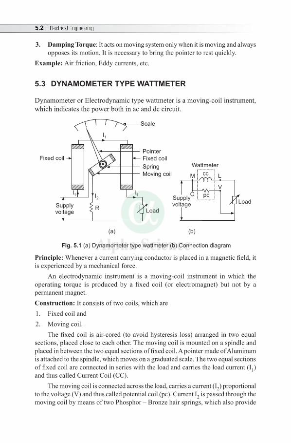
5.2 Electrical Engineering
3. Damping Torque: It acts on moving system only when it is moving and always opposes its motion. It is necessary to bring the pointer to rest quickly.
Example: Air friction, Eddy currents, etc.
5.3 DYNAMOMETER TYPE WATTMETER
Dynamometer or Electrodynamic type wattmeter is a moving-coil instrument, which indicates the power both in ac and dc circuit.
Scale
Fixed coil
Load
I1I2I1
Supplyvoltage
R
Pointer
Fixed coil
Spring
Moving coil
Supplyvoltage Load
Wattmeter
M
C
L
V
cc
pc
I1
(a) (b)
Fig. 5.1 (a) Dynamometer type wattmeter (b) Connection diagram
Principle: Whenever a current carrying conductor is placed in a magnetic field, it is experienced by a mechanical force.
An electrodynamic instrument is a moving-coil instrument in which the operating torque is produced by a fixed coil (or electromagnet) but not by a permanent magnet.Construction: It consists of two coils, which are1. Fixed coil and2. Moving coil.
The fixed coil is air-cored (to avoid hysteresis loss) arranged in two equal sections, placed close to each other. The moving coil is mounted on a spindle and placed in between the two equal sections of fixed coil. A pointer made of Aluminum is attached to the spindle, which moves on a graduated scale. The two equal sections of fixed coil are connected in series with the load and carries the load current (I1) and thus called Current Coil (CC).
The moving coil is connected across the load, carries a current (I2) proportional to the voltage (V) and thus called potential coil (pc). Current I2 is passed through the moving coil by means of two Phosphor – Bronze hair springs, which also provide
Measuring Instruments 5.3
the necessary controlling torque. To limit current (I2) through it a high resistance R is connected in series with moving coil. Working: The magnetic fields are set-up due to the current flowing in fixed and moving coil and hence two fluxes will set-up. These two fluxes will intersect and produces the deflecting torque. As a result, the moving coil rotates and the pointer moves on the graduated scale. The pointer reaches a steady deflection position when the deflecting torque (Td) is proportional to the controlling torque (Tc).
If the direction of current is reversed, the magnetic field will also get reversed so that direction of deflecting torque (Td) remains the same. Hence, it can be used to measure power consumed either by an ac circuit or a dc circuit.
Measurement of Power
Case (i) DC Circuit: Let V = Voltage across potential coilCurrent through fixed coil or CC = Load current = I1 Current through potential coil or pc = I2 ∝ VDeflecting torque, Td ∝ BI2 (where B = flux density)As the fixed coil is air-cored, flux density B ∝ I1
\ Td ∝ I1I2 ∝ I1 V = VI1
∝ PowerCase (ii) AC Circuit: Let the instantaneous voltage across the load,
v = Vm sin q voltAssuming lagging pf, instantaneous current flowing through CC or the load is i1 = Im sin (q – f) ampere ∝ I 1Current through moving coil = i2 ∝ vAverage deflecting torque, Td ∝ Average of i1 i2 ∝ Average of i1.v ∝ Vm sin wt × Im sin (q – f)
∝ VI1 cosq ∝ Power Controlling torque, Tc ∝ q At steady deflection position or equilibrium, Td ∝ Tc
or q ∝ Power Therefore, the scale is uniform.
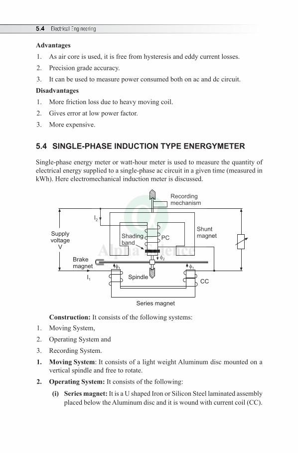
5.4 Electrical Engineering
Advantages1. As air core is used, it is free from hysteresis and eddy current losses.2. Precision grade accuracy.3. It can be used to measure power consumed both on ac and dc circuit.Disadvantages1. More friction loss due to heavy moving coil.2. Gives error at low power factor.3. More expensive.
5.4 SINGLE-PHASE INDUCTION TYPE ENERGYMETER
Single-phase energy meter or watt-hour meter is used to measure the quantity of electrical energy supplied to a single-phase ac circuit in a given time (measured in kWh). Here electromechanical induction meter is discussed.
Series magnet
CC
Shuntmagnet
Recordingmechanism
Spindle
Shadingband
Brakemagnet
Supplyvoltage
V
PC
I2
I1
1
2
1
Construction: It consists of the following systems:1. Moving System,2. Operating System and3. Recording System.1. Moving System: It consists of a light weight Aluminum disc mounted on a
vertical spindle and free to rotate.2. Operating System: It consists of the following:
(i) Series magnet: It is a U shaped Iron or Silicon Steel laminated assembly placed below the Aluminum disc and it is wound with current coil (CC).
Measuring Instruments 5.5
(ii) Shunt magnet: It is an M shaped Iron or Silicon Steel laminated assembly placed above the Aluminum disc and it is wound with pressure coil or potential coil (pc) or voltage coil.
(iii) Brake magnet: It is a permanent magnet placed at the edge of Aluminum disc, which controls the speed of the disc.
3. Recording System: It consists of a set of dials and gearing mechanism. It records the number of revolutions of the Aluminum disc.
Working: When the load current I1 flows through current coil of series magnet, it produces an alternating flux f1 proportional to I1 and exactly in-phase with it. When current I2 proportional to the voltage flows through potential coil of shunt magnet, it produces an alternating flux f2 proportional to voltage and lags behind it by 90°. These two fluxes f1 and f2 induce emfs in the Aluminum disc and hence produces circulating eddy currents.
The reaction between circulating eddy currents and fluxes produce a deflecting (or driving) torque, which causes the disc to rotate and its speed is controlled by brake magnet.
The function of Copper shading band is to ensure flux produced by pc is exactly in quadrature with supply voltage.
The meter constant of energy meter is given by revolutions/kWh.Computation of Electrical Energy:
Let, V = Supply Voltage in volt, I = Load or Line current in ampere N = Speed of the Aluminum disc. cosq = power factor of load\ Power consumed, P = VI cosq wattAverage deflecting torque, Td ∝ Por Td = K 1 VI cosq, where K1 is a constantBraking torque, Tb ∝ Nor Tb = K2 N, where K2 is some other constantThe Aluminum disc rotates at approximately steady speed N when Td = Tb i.e., K2 N = K1 VI cosq Multiplying by time t both the sides, K2 N × t = K1 VI cosq × t
or N × t = 1
2
KK
VI cosq × t

5.6 Electrical Engineering
or N × t = K P × t
where K = 1
2
KK
is another constant
Hence, the total number of revolutions in a given period of time t gives the electric energy consumed. (Note: Single-phase induction type energy meter is used only for the electric circuits energized by ac Supply.) Advantages1. Simple and strong in construction.2. It has high torque to weight ratio and thus frictional errors are less and gives
accurate readings.3. Less maintenance. Creep: In an induction type meter, creep is a phenomenon that can adversely affect accuracy, that occurs when the meter disc rotates continuously with potential applied and the load terminals open circuited.
Multiple Choice Questions
Choose the Correct Answer
1. The moving coil in a dynamometer wattmeter is connected (a) in series with fixed coil (b) across the supply (c) in series with the load (d) none of these
2. An electro dynamic instrument is a (a) moving iron instrument (b) moving coil instrument(c) induction (d) electrostatic
3. Dynamometer wattmeter is basically (a) an integrating instrument (b) an indicating instrument (c) a digital instrument (d) not an instrument
4. The pointer in dynamometer type wattmeter is made of ........(a) four (b) three (c) two (d) none of these
5. The fixed coil in dynamometer type wattmeter is arranged in ........ equal sections(a) copper (b) aluminum (c) phosphor bronze (d) platinum
6. Dynamometer type wattmeter is used to measure ........(a) only dc power (b) only ac power (c) both ac and dc power (d) both active and reactive power
Measuring Instruments 5.7
7. In dynamometer type wattmeter, the fixed coil is air-cored to avoid (a) copper loss (b) friction loss(c) hysteresis loss (d) none of these
8. In dynamometer type wattmeter, a resistance R is connected in series with pc to .......(a) increase the range (b) get uniform scale (c) limit the current through it (d) none of these
9. In dynamometer type wattmeter, Phosphor – Bronze hair springs provide(a) controlling torque (b) deflecting torque(c) both (a) and (b) (d) none of these
10. In dynamometer type wattmeter, at steady deflection position ........(a) Td < Tc (b) Td = Tc (c) Td > Tc (d) Td ∝ (1/Tc) where Td = deflecting torque and TC = controlling torque
11. When the pointer of an indicating instrument comes to rest in final deflection position, then(a) only controlling torque acts (b) only deflecting torque acts (c) both torques act (d) none of these
12. In the energy meter, constant speed of rotation of the disc is provided by(a) a shunt magnet (b) series magnet (c) braking magnet (d) none of these
13. The meter constant of energy meter is given by (a) rev./kW (b) rev./watt (c) rev./kWh (d) rev./kVA
14. One unit of electrical energy is equivalent to(a) 1 kWh (b) 3600 W-sec (c) 100 WH (d) 10 kWh
15. Induction type single phase energy meter can be used on(a) ac only (b) dc only(c) both ac and dc (d) none of these
16. In electricity bill, the units consumed represents(a) kW consumed (b) Wh consumed (c) kWh consumed (d) watts consumed
17. Exact value of true quantity being measured can be obtained from measuring instruments by(a) cleaning the instrument frequently (b) making proper connections (c) proper maintenance(d) proper calibration
5.8 Electrical Engineering
18. Under no load condition, the revolution of the disc due to kinetic energy of an energy meter can be blocked by(a) brake magnet (b) electromagnet (c) creeping hole with brake magnet (d) copper shading band
19. Single phase energy meter is (a) electro dynamic type of instrument (b) induction type of instrument (c) electrolytic type of instrument(d) motor type of instrument
20. Slow but continuous rotation of the disc of an energy meter is called(a) sweeping (b) crawling (c) creeping (d) friction error
Answers:—1. (b) 2. (b) 3. (b) 4. (c) 5. (b) 6. (c) 7. (c) 8. (c) 9. (a) 10. (c)
11. (c) 12. (c) 13. (c) 14. (a) 15. (a) 16. (c) 17. (d) 18. (a) 19. (b) 20. (c)
Review Questions
1. With a neat diagram, explain the working of dynamometer type wattmeter.2. Explain the principle of operation of dynamometer type of wattmeter.3. With the help of a neat figure, explain the single phase Induction type
energy meter.
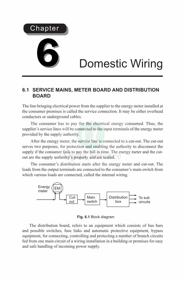
6.1 SERVICE MAINS, METER BOARD AND DISTRIBUTION BOARD
The line bringing electrical power from the supplier to the energy meter installed at the consumer premises is called the service connection. It may be either overhead conductors or underground cables.
The consumer has to pay for the electrical energy consumed. Thus, the supplier’s service lines will be connected to the input terminals of the energy meter provided by the supply authority.
After the energy meter, the service line is connected to a cut-out. The cut-out serves two purposes, for protection and enabling the authority to disconnect the supply if the consumer fails to pay the bill in time. The energy meter and the cut-out are the supply authority’s property and are sealed.
The consumer’s distribution starts after the energy meter and cut-out. The leads from the output terminals are connected to the consumer’s main switch from which various loads are connected, called the internal wiring.
Energymeter
EM
Cut-out
To subcircuits
Mainswitch
Distributionbox
Fig. 6.1 Block diagram
The distribution board, refers to an equipment which consists of bus bars and possible switches, fuse links and automatic protective equipment, bypass equipment, for connecting, controlling and protecting a number of branch circuits fed from one main circuit of a wiring installation in a building or premises for easy and safe handling of incoming power supply.
Domestic Wiring6Chapter
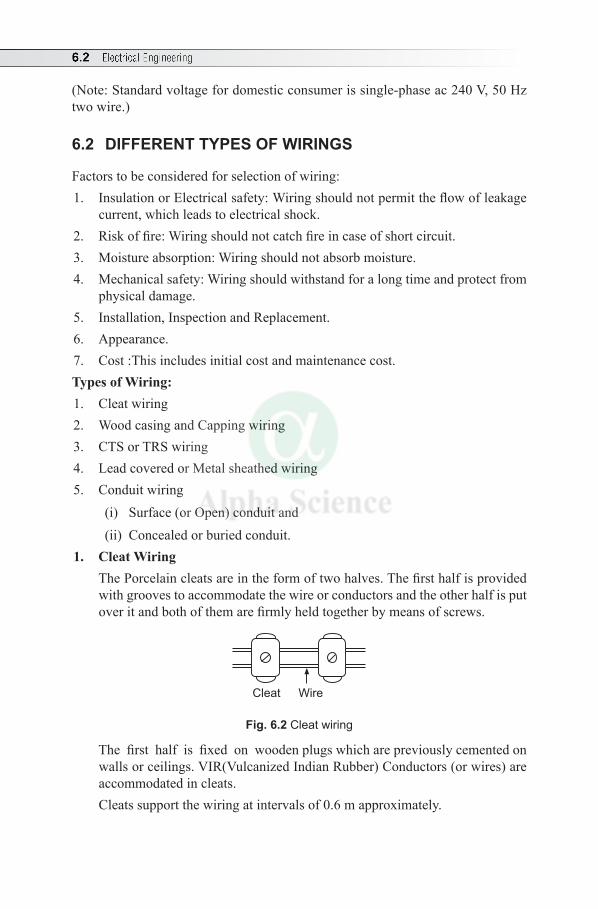
6.2 Electrical Engineering
(Note: Standard voltage for domestic consumer is single-phase ac 240 V, 50 Hz two wire.)
6.2 DIFFERENT TYPES OF WIRINGS
Factors to be considered for selection of wiring:1. Insulation or Electrical safety: Wiring should not permit the flow of leakage
current, which leads to electrical shock.2. Risk of fire: Wiring should not catch fire in case of short circuit.3. Moisture absorption: Wiring should not absorb moisture.4. Mechanical safety: Wiring should withstand for a long time and protect from
physical damage.5. Installation, Inspection and Replacement.6. Appearance.7. Cost :This includes initial cost and maintenance cost.Types of Wiring: 1. Cleat wiring2. Wood casing and Capping wiring3. CTS or TRS wiring4. Lead covered or Metal sheathed wiring 5. Conduit wiring
(i) Surface (or Open) conduit and(ii) Concealed or buried conduit.
1. Cleat Wiring The Porcelain cleats are in the form of two halves. The first half is provided
with grooves to accommodate the wire or conductors and the other half is put over it and both of them are firmly held together by means of screws.
Cleat Wire
Fig. 6.2 Cleat wiring
The first half is fixed on wooden plugs which are previously cemented on walls or ceilings. VIR(Vulcanized Indian Rubber) Conductors (or wires) are accommodated in cleats. Cleats support the wiring at intervals of 0.6 m approximately.
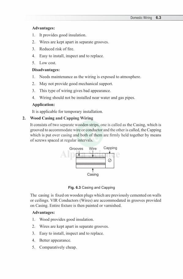
Domestic Wiring 6.3
Advantages:1. It provides good insulation.2. Wires are kept apart in separate grooves.3. Reduced risk of fire.4. Easy to install, inspect and to replace.5. Low cost.Disadvantages:1. Needs maintenance as the wiring is exposed to atmosphere.2. May not provide good mechanical support.3. This type of wiring gives bad appearance.4. Wiring should not be installed near water and gas pipes. Application: It is applicable for temporary installation.
2. Wood Casing and Capping Wiring It consists of two separate wooden strips, one is called as the Casing, which is
grooved to accommodate wire or conductor and the other is called, the Capping which is put over casing and both of them are firmly held together by means of screws spaced at regular intervals.
CappingGrooves
Casing
Wire
Fig. 6.3 Casing and Capping
The casing is fixed on wooden plugs which are previously cemented on walls or ceilings. VIR Conductors (Wires) are accommodated in grooves provided on Casing. Entire fixture is then painted or varnished.Advantages:1. Wood provides good insulation.2. Wires are kept apart in separate grooves. 3. Easy to install, inspect and to replace.4. Better appearance.5. Comparatively cheap.

6.4 Electrical Engineering
Disadvantages:1. Risk of fire.
2. Absorbs moisture.
3. If seasoned wood is not used, there may be trouble from white ants.
4. Requires skilled workmanship.
5. Wiring should not be installed near water and gas pipes.
Application:
Applicable for permanent wiring system under dry conditions.
3. CTS or TRS Wiring
Teak wood battens are fixed on wooden plugs, which are previously cemented on walls or ceilings.
Wire
Wooden battens
Fig. 6.4 Wiring
Cab – Tyre – Sheathed (CTS) or Tough Rubber Sheathed (TRS) Conductors are insulated conductors, which are completely covered by means of a thick coating of tough rubber. The wiring is accommodated on wooden battens and held firmly by lead or steel strips. The entire fixture is then varnished or painted.Advantages:1. Provides good insulation.2. Reduced risk of fire.3. Easy to install, inspect and to replace.4. Better appearance.5. Economical.Disadvantages:1. Wiring should not be exposed to direct Sun light, rain or damp places.2. Sharp bends should be avoided.3. Must be adequately protected against mechanical injury.4. Wiring should not be installed near water and gas pipes. Applications:It was most commonly used.
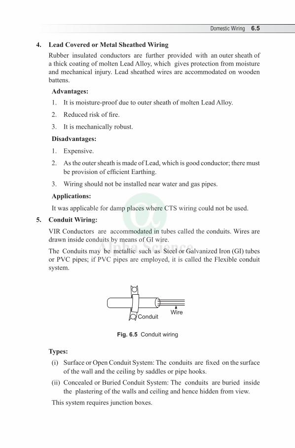
Domestic Wiring 6.5
4. Lead Covered or Metal Sheathed Wiring Rubber insulated conductors are further provided with an outer sheath of
a thick coating of molten Lead Alloy, which gives protection from moisture and mechanical injury. Lead sheathed wires are accommodated on wooden battens.Advantages:1. It is moisture-proof due to outer sheath of molten Lead Alloy.
2. Reduced risk of fire.
3. It is mechanically robust.
Disadvantages:
1. Expensive.
2. As the outer sheath is made of Lead, which is good conductor; there must be provision of efficient Earthing.
3. Wiring should not be installed near water and gas pipes.
Applications:
It was applicable for damp places where CTS wiring could not be used.
5. Conduit Wiring:
VIR Conductors are accommodated in tubes called the conduits. Wires are drawn inside conduits by means of GI wire.
The Conduits may be metallic such as Steel or Galvanized Iron (GI) tubes or PVC pipes; if PVC pipes are employed, it is called the Flexible conduit system.
WireConduit
Fig. 6.5 Conduit wiring
Types:(i) Surface or Open Conduit System: The conduits are fixed on the surface
of the wall and the ceiling by saddles or pipe hooks.(ii) Concealed or Buried Conduit System: The conduits are buried inside
the plastering of the walls and ceiling and hence hidden from view.This system requires junction boxes.

6.6 Electrical Engineering
Advantages:1. It provides very good insulation.2. Risk of fire is completely eliminated.3. It is moisture-proof.4. It provides good mechanical support.5. Easy to replace.Disadvantages:1. Initial cost is more.2. Skilled workers are required.3. Wiring should not be installed near water and gas pipes.Applications:It is considered as the best type of wiring and most popular one.Specification of Wires:
The current flowing through a wire causes heat, which is proportional to square of current. Therefore it requires proper insulation to withstand this temperature safely.
Resistance is given by
R = lA
r
where r = specific resistance of material, l = length of conductor A = cross sectional area Hence, if the current is more, resistance of conductor should be less and should
have larger area of cross section. As per Metric System, wire is specified as Standard Wire Gauge (SWG). For
solid (or single) conductor, the size of wires are denoted by their area of cross-section in square millimeters.
Example: 1.5 sq. mm, 2.5 sq. mm., etc. For the sake of convenience, the size of wire is referred to the number rather
than area of cross section. Higher the number of gauge, smaller is the diameter. Example: Smallest wire gauge is of number 40 having diameter of 0.0048 inch. The largest wire gauge is of number 0,000,000 (seven zero) having diameter of 0.5 inch.
For flexible wires, which consists of a number of wires stranded together, the wires of standard size of diameter 0.1930 mm (equivalent of 36 SWG wire of diameter 0.0076 inch) are used.
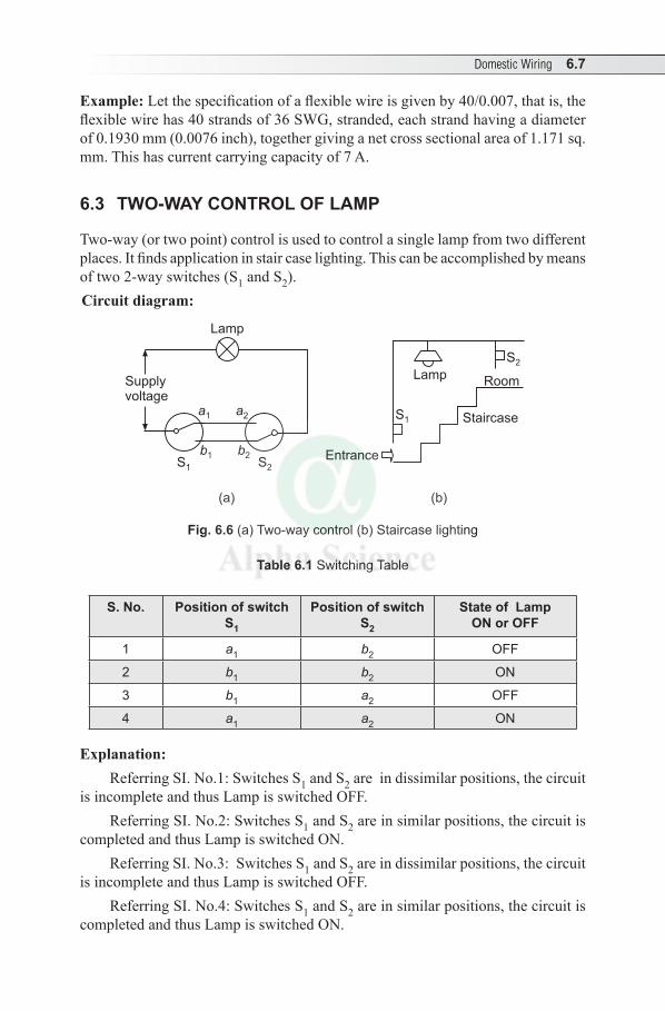
Domestic Wiring 6.7
Example: Let the specification of a flexible wire is given by 40/0.007, that is, the flexible wire has 40 strands of 36 SWG, stranded, each strand having a diameter of 0.1930 mm (0.0076 inch), together giving a net cross sectional area of 1.171 sq. mm. This has current carrying capacity of 7 A.
6.3 TWO-WAY CONTROL OF LAMP
Two-way (or two point) control is used to control a single lamp from two different places. It finds application in stair case lighting. This can be accomplished by means of two 2-way switches (S1 and S2).Circuit diagram:
Supplyvoltage
Lamp
a2
b2
a1
b1S1 S2
S1 Staircase
Entrance
S2
RoomLamp
(a) (b)
Fig. 6.6 (a) Two-way control (b) Staircase lighting
Table 6.1 Switching Table
S. No. Position of switchS1
Position of switchS2
State of LampON or OFF
1 a1 b2 OFF
2 b1 b2 ON
3 b1 a2 OFF
4 a1 a2 ON
Explanation:Referring SI. No.1: Switches S1 and S2 are in dissimilar positions, the circuit
is incomplete and thus Lamp is switched OFF.Referring SI. No.2: Switches S1 and S2 are in similar positions, the circuit is
completed and thus Lamp is switched ON.Referring SI. No.3: Switches S1 and S2 are in dissimilar positions, the circuit
is incomplete and thus Lamp is switched OFF.Referring SI. No.4: Switches S1 and S2 are in similar positions, the circuit is
completed and thus Lamp is switched ON.
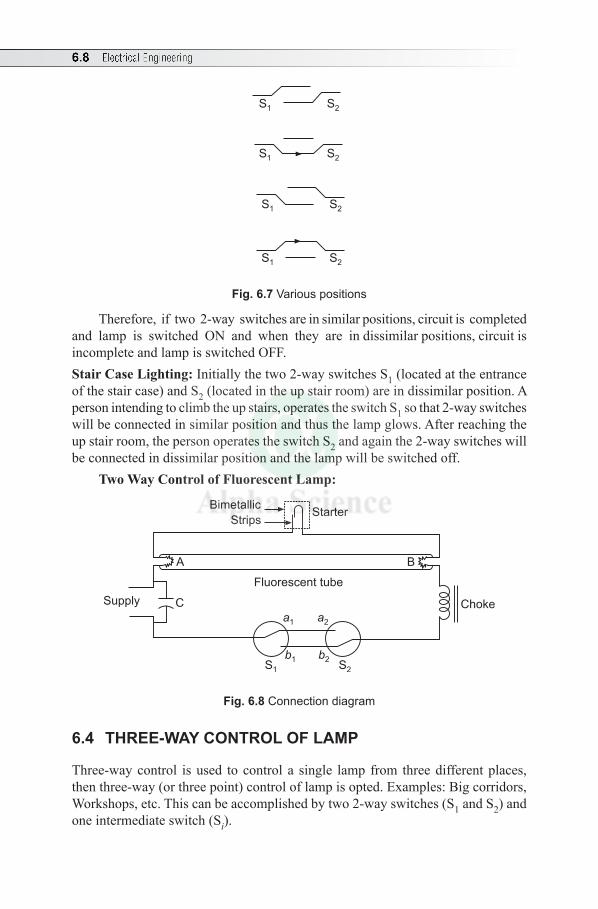
6.8 Electrical Engineering
S1
S1
S1
S1
S2
S2
S2
S2
Fig. 6.7 Various positions
Therefore, if two 2-way switches are in similar positions, circuit is completed and lamp is switched ON and when they are in dissimilar positions, circuit is incomplete and lamp is switched OFF.Stair Case Lighting: Initially the two 2-way switches S1 (located at the entrance of the stair case) and S2 (located in the up stair room) are in dissimilar position. A person intending to climb the up stairs, operates the switch S1 so that 2-way switches will be connected in similar position and thus the lamp glows. After reaching the up stair room, the person operates the switch S2 and again the 2-way switches will be connected in dissimilar position and the lamp will be switched off.
Two Way Control of Fluorescent Lamp:
Choke
StarterBimetallic
Strips
Supply C
Fluorescent tube
A B
a1
b1
a2
b2S2S1
Fig. 6.8 Connection diagram
6.4 THREE-WAY CONTROL OF LAMP
Three-way control is used to control a single lamp from three different places, then three-way (or three point) control of lamp is opted. Examples: Big corridors, Workshops, etc. This can be accomplished by two 2-way switches (S1 and S2) and one intermediate switch (Si).
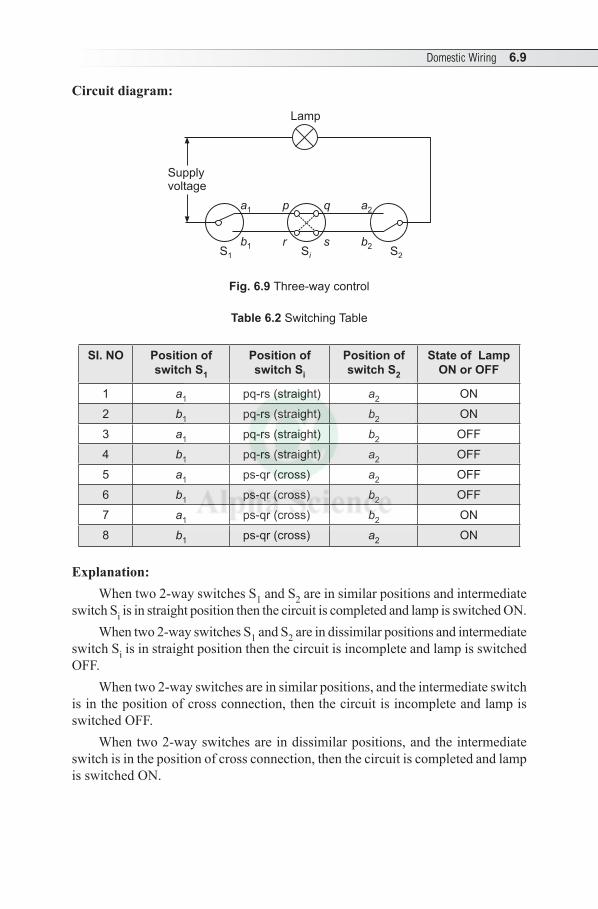
Domestic Wiring 6.9
Circuit diagram:
Lamp
Supplyvoltage
a1
b1
a2
b2
p
r
q
sS1 S
iS2
Fig. 6.9 Three-way control
Table 6.2 Switching Table
SI. NO Position of switch S1
Position of switch Si
Position of switch S2
State of LampON or OFF
1 a1 pq-rs (straight) a2 ON
2 b1 pq-rs (straight) b2 ON
3 a1 pq-rs (straight) b2 OFF
4 b1 pq-rs (straight) a2 OFF
5 a1 ps-qr (cross) a2 OFF
6 b1 ps-qr (cross) b2 OFF
7 a1 ps-qr (cross) b2 ON
8 b1 ps-qr (cross) a2 ON
Explanation:When two 2-way switches S1 and S2 are in similar positions and intermediate
switch Si is in straight position then the circuit is completed and lamp is switched ON.When two 2-way switches S1 and S2 are in dissimilar positions and intermediate
switch Si is in straight position then the circuit is incomplete and lamp is switched OFF.
When two 2-way switches are in similar positions, and the intermediate switch is in the position of cross connection, then the circuit is incomplete and lamp is switched OFF.
When two 2-way switches are in dissimilar positions, and the intermediate switch is in the position of cross connection, then the circuit is completed and lamp is switched ON.
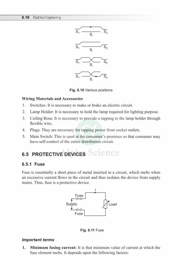
6.10 Electrical Engineering
S1
S1
S1
S1
S2
S2
S2
S2
Si
Si
Si
Si
Fig. 6.10 Various positions
Wiring Materials and Accessories1. Switches: It is necessary to make or brake an electric circuit. 2. Lamp Holder: It is necessary to hold the lamp required for lighting purpose.3. Ceiling Rose: It is necessary to provide a tapping to the lamp holder through
flexible wire.4. Plugs: They are necessary for tapping power from socket outlets.5. Main Switch: This is used at the consumer’s premises so that consumer may
have self-control of the entire distribution circuit.
6.5 PROTECTIVE DEVICES
6.5.1 Fuse
Fuse is essentially a short piece of metal inserted in a circuit, which melts when an excessive current flows in the circuit and thus isolates the device from supply mains. Thus, fuse is a protective device.
Supply
Fuse
Fuse
I
Load
Fig. 6.11 Fuse
Important terms
1. Minimum fusing current: It is that minimum value of current at which the fuse element melts. It depends upon the following factors:
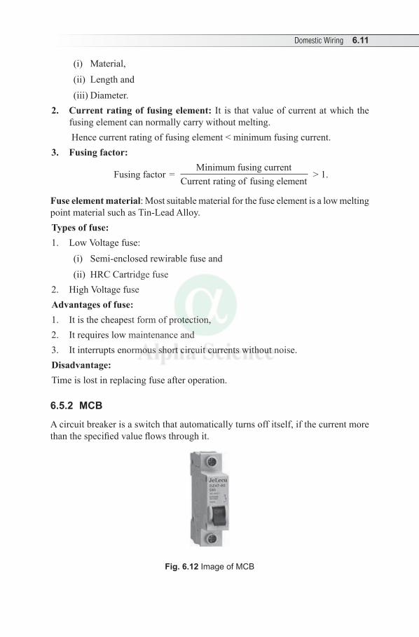
Domestic Wiring 6.11
(i) Material,(ii) Length and(iii) Diameter.
2. Current rating of fusing element: It is that value of current at which the fusing element can normally carry without melting. Hence current rating of fusing element < minimum fusing current.
3. Fusing factor:
Fusing factor = Minimum fusing current
Current rating fusing elementof > 1.
Fuse element material: Most suitable material for the fuse element is a low melting point material such as Tin-Lead Alloy.Types of fuse: 1. Low Voltage fuse:
(i) Semi-enclosed rewirable fuse and(ii) HRC Cartridge fuse
2. High Voltage fuseAdvantages of fuse: 1. It is the cheapest form of protection,2. It requires low maintenance and3. It interrupts enormous short circuit currents without noise.Disadvantage:Time is lost in replacing fuse after operation.
6.5.2 MCB
A circuit breaker is a switch that automatically turns off itself, if the current more than the specified value flows through it.
Fig. 6.12 Image of MCB
6.12 Electrical Engineering
Circuit breakers used in residential and light commercial installations are referred to as miniature circuit breakers (MCB’s).They are commonly used in the electrical consumer units as protective devices and installed in consumer units.
MCB consists of a movable handle in the form of a lever. Under normal working conditions, the lever will be in ON position. If a fault occurs either due to over loading of the circuit or short circuit, MCB trips and switches OFF automatically, isolating the electrical equipment from the supply. Then it can be manually reset.
6.6 ELECTRIC SHOCK, PRECAUTIONS AGAINST SHOCK-EARTHING
Electric Shock
If a live wire carrying electric current is in contact with the metal parts of an electric equipment and if a person happens to touch the such metal parts, then the current (leakage current) flows through that person and the person experiences electric shock. It may cause injury, burns, unconsciousness or even death if the shock is severe.
As the leakage is given by V/R, severity depends upon the voltage and the human body resistance (it is approximately 100 kW under dry condition and 1 kW under wet condition). Also, current at low frequency may cause severe shock than that of high frequency.
A human being can sustain about 30 mA for a short duration of 25 millisecond. If the current is of the range 100 mA, the severity of shock will be more.Precautions against shock:1. Electric appliances and switches should not be touched with wet hands.2. Proper grounding should be provided. 3. Three pin sockets are to be used and ground point should be provided to all
the sockets.4. The earth resistance should be periodically checked and it should not exceed
5W.5. ‘Ground Fault Interrupt’ may be provided for extra safety.6. Worn wiring and cords should be replaced.
Earthing or Grounding
Meaning: Earthing or Grounding means, connection of the metal frame of an electrical equipment or machinery to the general mass of earth so that it will ensure at all times an immediate and safe discharge of electrical energy due to leakage or faults.

Domestic Wiring 6.13
Earthing is done by connecting the metal frame or casing of electrical apparatus or machinery to the earth by means an earth wire having low resistance, called ‘Earth wire’ or ‘Earth electrode’. Its function is to prevent the risk of shock due to leakage or faults.
Necessity of Earthing
1. If human body happens to come in contact with metal frame of an electrical equipment or machinery, the leakage current due to faults flows through human body to earth, which causes electric shock. The electrical shock may cause disability or even death. Hence to protect human being from shock, earthing is done.
2. For the purpose of protection, all electrical equipments and machines shall be earthed.
Working (or functioning)
With effective earthing, if a person happens to touch the metal frame of an electrical equipment or machinery, when the live wire is in touch with it, it forms a parallel path, thus a circuit will be completed through human body and earth wire.
As earth wire has very low resistance compared to human body, the leakage current flows through earth wire and hence human body will be protected. Thus earth wire works as a protective device against any electrical shock in case of faults in the circuit.
6.7 TYPES OF EARTHING
1. Pipe earthing and2. Plate earthing
6.7.1 Pipe Earthing
The GI Pipe is used as an earth electrode. It is buried at a depth not less than 3 metre in a moist place as for as possible, near by water tap or drainage and should be away from building and foundation by 0.6 m. Also, for effectiveness, salt water is poured periodically through a funnel provided.
The pit area around the pipe must be completely filled by a layer of charcoal (80 mm) and a layer of common salt (30 mm) all around to increase earth’s conductivity.
Size of pipe depends upon the current to be carried and type of soil.(i) For ordinary soil; 38 mm dia. and 2 m length.(ii) For dry and rocky soil; 38 mm dia. and 2.75 m length.
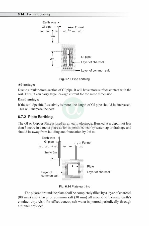
6.14 Electrical Engineering
2m
2m
GI pipe
Earth wire
Funnel
GI pipe
Layer of charcoal
Layer of common salt
Fig. 6.13 Pipe earthing
Advantage:Due to circular cross-section of GI pipe, it will have more surface contact with the soil. Thus, it can carry large leakage current for the same dimension.Disadvantage:If the soil Specific Resistivity is more, the length of GI pipe should be increased. This will increase the cost.
6.7.2 Plate Earthing
The GI or Copper Plate is used as an earth electrode. Burried at a depth not less than 3 metre in a moist place as for as possible, near by water tap or drainage and should be away from building and foundation by 0.6 m.
2m to 3m
GI pipe
Earth wire
Funnel
Plate
Layer of charcoalLayer ofcommon salt
Fig. 6.14 Plate earthing
The pit area around the plate shall be completely filled by a layer of charcoal (80 mm) and a layer of common salt (30 mm) all around to increase earth’s conductivity. Also, for effectiveness, salt water is poured periodically through a funnel provided.

Domestic Wiring 6.15
Plate dimension: (i) GI Plate: 0.3 m × 0.3 m × 3.2 mm thickness. (ii) Copper Plate: 0.3 m × 0.3 m × 6.35 mm thickness.Advantages:1. Conductivity can be increased by increasing the dimension of the plate and
depth of embedding. 2. Cheaper if GI pipe is opted.Disadvantages:1. Sometimes the earth wire may get disconnected with earth plate, which could
not be noticed. 2. Becomes expensive if Copper plate is opted.
Multiple Choice Questions
Choose the Correct Answer
1. For stair case lighting, usually ........ control is used.(a) one way (b) two way (c) three way (d) none of these
2. An intermediate switch is used in ........ of lamps.(a) single way control (b) two way control(c) three way control (d) both (a) and (b)
3. The resistivity of a fuse material is of the order of ....... mW-m(a) 102 (b) 10–2 (c) 104 (d) 10–4
4. The minimum fusing current of a fuse wire is 2.1 A and fusing factor is 1.1. Then, the rated carrying current of the fuse element is (a) 2.2 A (b) 2.31 A (c) 1.909 A (d) 0.5238 A
5. A fuse is a (a) current limiting device (b) protective device (c) voltage limiting device (d) none of these
6 The fusing factor of a fuse is(a) zero (b) = 1 (c) > 1 (d) < 1
7. The fuse material is made of ........(a) an alloy of tin and lead (b) aluminum(c) copper (d) zinc
6.16 Electrical Engineering
8. The important properties of a fuse wire are ........(a) low resistivity and high melting point(b) high resistivity and low melting point (c) low resistivity and low melting point(d) high resistivity and high melting point
9. The primary function of fuse is to ........(a) protect the appliance (b) open the circuit (c) prevent excessive current (d) protect the line
10. Charcoal and salt used in earthing ........(a) not to alter the earthing resistance(b) to increase the earthing resistance (c) to decrease earthing resistance(d) none of these
11. Coke can be used as a sandwich between salt of an earthing system, to.......(a) by pass the current(b) avoid melting of salt (c) improve conductivity(d) hold moisture content
12. Earthing brings the potential of the body of the equipment to ......(a) 0 (b) 110 V (c) 220 V (d) 400 V
13. The earthing resistance for effective earthing is of the order of ....... W.(a) 0.5 (b) 5 (c) 50 (d) 500
14. A good earthing should provide ........ resistance in earthing plate.(A) low (b) high (c) medium (d) none of these
15. Severity of electric shock depends upon(a) current and earthing resistance(b) voltage and earthing resistance (c) body resistance and body resistance (d) voltage and body resistance
Answers:—1. (b) 2. (c) 3. (b) 4. (c) 5. (b) 6. (c) 7. (a) 8. (b) 9. (b) 10. (c)
11. (c) 12. (a) 13. (b) 14. (a) 15. (d)
Domestic Wiring 6.17
Review Questions
1. Discuss the supply mains, meter board and distribution board.2. Describe briefly:
(i) Conduit system of wiring(ii) CTS System of wiring
3. With neat diagrams explain any three types of wiring.4. With relevant circuit diagrams and switching tables, explain two-way control
of lamp.5. With diagrams, explain the three way control of lamp.6. What is the necessity of earthing? With a neat diagram explain the pipe earthing.7. With a neat sketch explain the plate earthing method.8. Define the following terms with respect to a fuse:
(i) Rated current(ii) Fusing current(iii) Fusing factor
9. Write a note on MCB.10. What are the precautions to be taken to prevent electric shock?
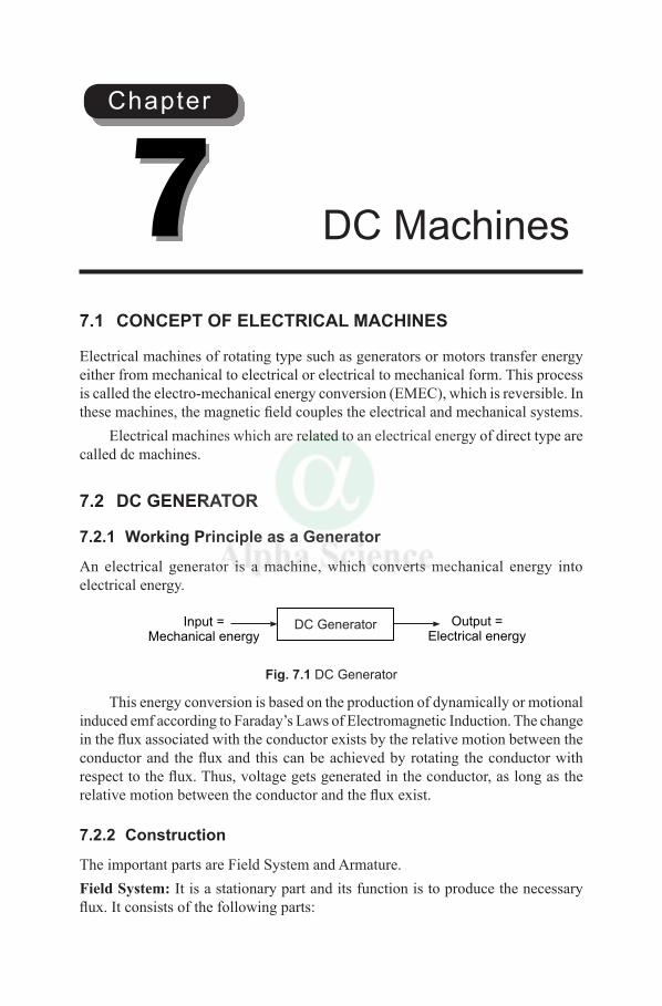
7.1 CONCEPT OF ELECTRICAL MACHINES
Electrical machines of rotating type such as generators or motors transfer energy either from mechanical to electrical or electrical to mechanical form. This process is called the electro-mechanical energy conversion (EMEC), which is reversible. In these machines, the magnetic field couples the electrical and mechanical systems.
Electrical machines which are related to an electrical energy of direct type are called dc machines.
7.2 DC GENERATOR
7.2.1 Working Principle as a Generator
An electrical generator is a machine, which converts mechanical energy into electrical energy.
DC GeneratorInput =Mechanical energy
Output =Electrical energy
Fig. 7.1 DC Generator
This energy conversion is based on the production of dynamically or motional induced emf according to Faraday’s Laws of Electromagnetic Induction. The change in the flux associated with the conductor exists by the relative motion between the conductor and the flux and this can be achieved by rotating the conductor with respect to the flux. Thus, voltage gets generated in the conductor, as long as the relative motion between the conductor and the flux exist.
7.2.2 Construction
The important parts are Field System and Armature.Field System: It is a stationary part and its function is to produce the necessary flux. It consists of the following parts:
DC Machines7Chapter
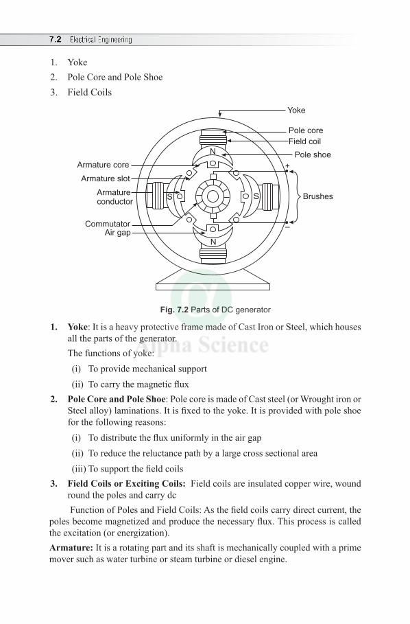
7.2 Electrical Engineering
1. Yoke2. Pole Core and Pole Shoe 3. Field Coils
+
Brushes
Yoke
Pole core
Field coil
Pole shoe
Air gapCommutator
Armatureconductor
Armature core
Armature slot
N
N
S S
–
Fig. 7.2 Parts of DC generator
1. Yoke: It is a heavy protective frame made of Cast Iron or Steel, which houses all the parts of the generator.
The functions of yoke:(i) To provide mechanical support (ii) To carry the magnetic flux
2. Pole Core and Pole Shoe: Pole core is made of Cast steel (or Wrought iron or Steel alloy) laminations. It is fixed to the yoke. It is provided with pole shoe for the following reasons:(i) To distribute the flux uniformly in the air gap(ii) To reduce the reluctance path by a large cross sectional area(iii) To support the field coils
3. Field Coils or Exciting Coils: Field coils are insulated copper wire, wound round the poles and carry dc Function of Poles and Field Coils: As the field coils carry direct current, the
poles become magnetized and produce the necessary flux. This process is called the excitation (or energization).Armature: It is a rotating part and its shaft is mechanically coupled with a prime mover such as water turbine or steam turbine or diesel engine.
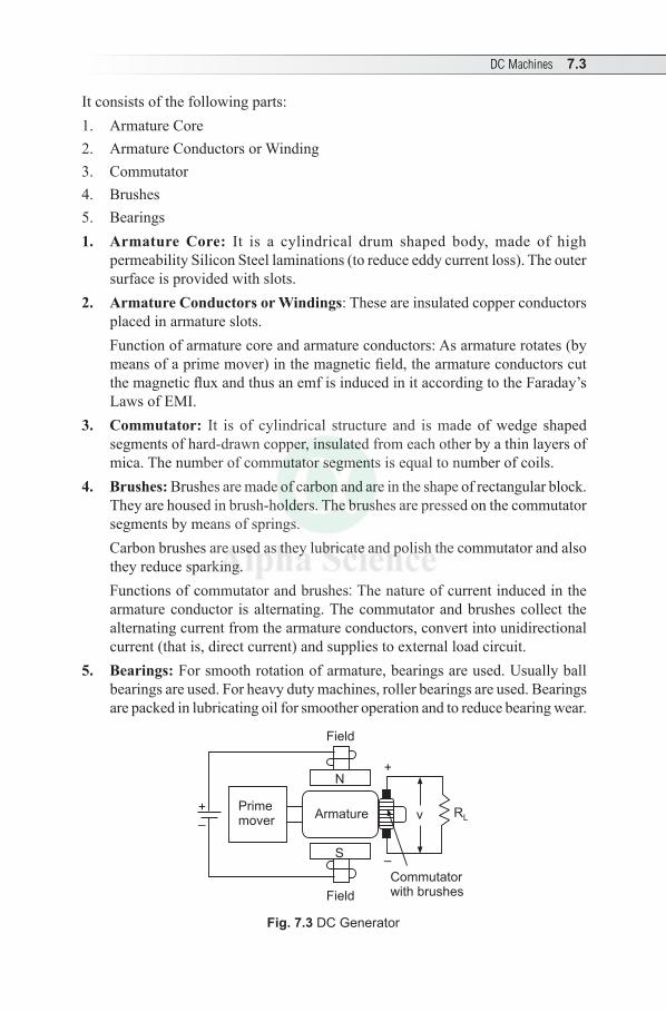
DC Machines 7.3
It consists of the following parts:1. Armature Core2. Armature Conductors or Winding3. Commutator4. Brushes 5. Bearings1. Armature Core: It is a cylindrical drum shaped body, made of high
permeability Silicon Steel laminations (to reduce eddy current loss). The outer surface is provided with slots.
2. Armature Conductors or Windings: These are insulated copper conductors placed in armature slots.
Function of armature core and armature conductors: As armature rotates (by means of a prime mover) in the magnetic field, the armature conductors cut the magnetic flux and thus an emf is induced in it according to the Faraday’s Laws of EMI.
3. Commutator: It is of cylindrical structure and is made of wedge shaped segments of hard-drawn copper, insulated from each other by a thin layers of mica. The number of commutator segments is equal to number of coils.
4. Brushes: Brushes are made of carbon and are in the shape of rectangular block. They are housed in brush-holders. The brushes are pressed on the commutator segments by means of springs.
Carbon brushes are used as they lubricate and polish the commutator and also they reduce sparking.
Functions of commutator and brushes: The nature of current induced in the armature conductor is alternating. The commutator and brushes collect the alternating current from the armature conductors, convert into unidirectional current (that is, direct current) and supplies to external load circuit.
5. Bearings: For smooth rotation of armature, bearings are used. Usually ball bearings are used. For heavy duty machines, roller bearings are used. Bearings are packed in lubricating oil for smoother operation and to reduce bearing wear.
+
–v
Field
Commutatorwith brushes
Field
Primemover
Armature
N
S
+
–
RL
Fig. 7.3 DC Generator
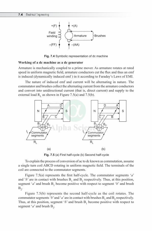
7.4 Electrical Engineering
+(F) +(A)
–(FF) –(AA)
Fieldwinding Armature Brushes
Fig. 7.4 Symbolic representation of dc machine
Working of a dc machine as a dc generatorArmature is mechanically coupled to a prime mover. As armature rotates at rated speed in uniform magnetic field, armature conductors cut the flux and thus an emf is induced (dynamically induced emf ) in it according to Faraday’s Laws of EMI.
The nature of induced emf and current will be alternating in nature. The commutator and brushes collect the alternating current from the armature conductors and convert into unidirectional current (that is, direct current) and supply to the external load RL as shown in Figure 7.5(a) and 7.5(b).
N S
CB
DA
B1 B2
IL
RL
Commutatorsegments
a b
N S
BC
AD
B1 B2
IL
RL
Commutatorsegments
b a
(a) (b)
Fig. 7.5 (a) First half-cycle (b) Second half-cycle
To explain the process of conversion of ac to dc known as commutation, assume a single turn coil ABCD rotating in uniform magnetic field. The terminals of the coil are connected to the commutator segments.
Figure 7.5(a) represents the first half-cycle. The commutator segments ‘a’ and ‘b’ are in contact with brushes B1 and B2 respectively. Thus, at this position, segment ‘a’ and brush B1 become positive with respect to segment ‘b’ and brush B2.
Figure 7.5(b) represents the second half-cycle as the coil rotates. The commutator segments ‘b’ and ‘a’ are in contact with brushes B1 and B2 respectively. Thus, at this position, segment ‘b’ and brush B1 become positive with respect to segment ‘a’ and brush B2.
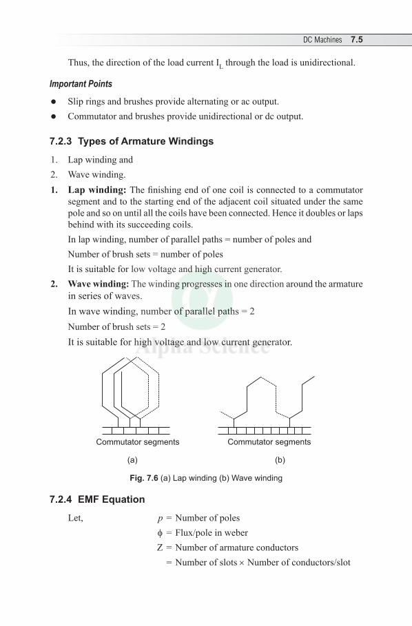
DC Machines 7.5
Thus, the direction of the load current IL through the load is unidirectional.
Important Points
l Slip rings and brushes provide alternating or ac output.lCommutator and brushes provide unidirectional or dc output.
7.2.3 Types of Armature Windings
1. Lap winding and2. Wave winding.1. Lap winding: The finishing end of one coil is connected to a commutator
segment and to the starting end of the adjacent coil situated under the same pole and so on until all the coils have been connected. Hence it doubles or laps behind with its succeeding coils.
In lap winding, number of parallel paths = number of poles and Number of brush sets = number of poles
It is suitable for low voltage and high current generator.2. Wave winding: The winding progresses in one direction around the armature
in series of waves.In wave winding, number of parallel paths = 2Number of brush sets = 2It is suitable for high voltage and low current generator.
Commutator segmentsCommutator segments
(a) (b)
Fig. 7.6 (a) Lap winding (b) Wave winding
7.2.4 EMF Equation
Let, p = Number of poles f = Flux/pole in weber Z = Number of armature conductors = Number of slots × Number of conductors/slot
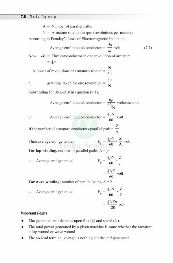
7.6 Electrical Engineering
A = Number of parallel paths N = Armature rotation in rpm (revolutions per minute)According to Faraday’s Laws of Electromagnetic Induction,
Average emf induced/conductor = fd
dt volt ...(7.1)
Now df = Flux cut/conductor in one revolution of armature = fp
Number of revolutions of armature/second = N60
\ dt = time taken for one revolution = 60N
Substituting for df and dt in equation (7.1),
Average emf induced/conductor = 60N
fp weber/second
or Average emf induced/conductor = N
60pf
volt
If the number of armature conductors/parallel path = ZA
;
Then average emf generated, Eg = N Z
60 Apf
× volt
For lap winding, number of parallel paths, A = p
\ Average emf generated, Eg = N Z
60p
pf
×
= NZ volt60
f
For wave winding; number of parallel paths, A = 2
\ Average emf generated, Eg = N Z×60 2pf
= NZ volt120
pf
Important Points
l The generated emf depends upon flux (f) and speed (N).l The total power generated by a given machine is same whether the armature
is lap wound or wave wound.l The no-load terminal voltage is nothing but the emf generated.
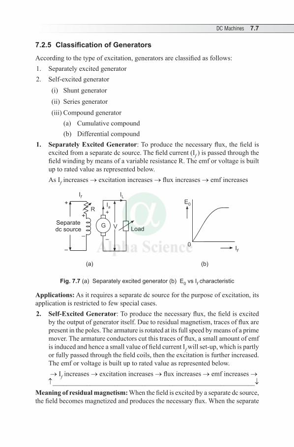
DC Machines 7.7
7.2.5 ClassificationofGenerators
According to the type of excitation, generators are classified as follows:1. Separately excited generator2. Self-excited generator
(i) Shunt generator (ii) Series generator (iii) Compound generator
(a) Cumulative compound(b) Differential compound
1. Separately Excited Generator: To produce the necessary flux, the field is excited from a separate dc source. The field current (If ) is passed through the field winding by means of a variable resistance R. The emf or voltage is built up to rated value as represented below. As If increases → excitation increases → flux increases → emf increases
G V
+
–
Load
IL
Ia
R
If
+
–
+
–
Separatedc source
If
E0
0
(a) (b)
Fig. 7.7 (a) Separately excited generator (b) E0 vs If characteristic
Applications: As it requires a separate dc source for the purpose of excitation, its application is restricted to few special cases.2. Self-Excited Generator: To produce the necessary flux, the field is excited
by the output of generator itself. Due to residual magnetism, traces of flux are present in the poles. The armature is rotated at its full speed by means of a prime mover. The armature conductors cut this traces of flux, a small amount of emf is induced and hence a small value of field current If will set-up, which is partly or fully passed through the field coils, then the excitation is further increased. The emf or voltage is built up to rated value as represented below. → If increases → excitation increases → flux increases → emf increases →↑___________________________________________________________↓
Meaning of residual magnetism: When the field is excited by a separate dc source, the field becomes magnetized and produces the necessary flux. When the separate
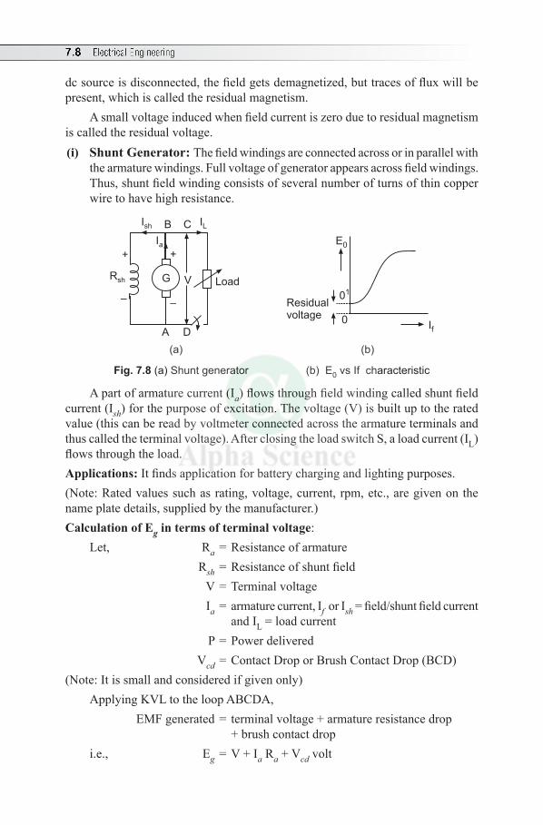
7.8 Electrical Engineering
dc source is disconnected, the field gets demagnetized, but traces of flux will be present, which is called the residual magnetism.
A small voltage induced when field current is zero due to residual magnetism is called the residual voltage.(i) Shunt Generator: The field windings are connected across or in parallel with
the armature windings. Full voltage of generator appears across field windings. Thus, shunt field winding consists of several number of turns of thin copper wire to have high resistance.
RaG V
+
–
Load
IL
Ia
If
E0
0
Ish B C
+
Rsh
A D
01
Residualvoltage
–
(a) (b)
Fig. 7.8 (a) Shunt generator (b) E0 vs If characteristic
A part of armature current (Ia) flows through field winding called shunt field current (Ish) for the purpose of excitation. The voltage (V) is built up to the rated value (this can be read by voltmeter connected across the armature terminals and thus called the terminal voltage). After closing the load switch S, a load current (IL) flows through the load.Applications: It finds application for battery charging and lighting purposes.(Note: Rated values such as rating, voltage, current, rpm, etc., are given on the name plate details, supplied by the manufacturer.)Calculation of Eg in terms of terminal voltage:
Let, Ra = Resistance of armature Rsh = Resistance of shunt field V = Terminal voltage Ia = armature current, If or Ish = field/shunt field current and IL = load current P = Power delivered Vcd = Contact Drop or Brush Contact Drop (BCD)
(Note: It is small and considered if given only)Applying KVL to the loop ABCDA, EMF generated = terminal voltage + armature resistance drop + brush contact dropi.e., Eg = V + Ia Ra + Vcd volt
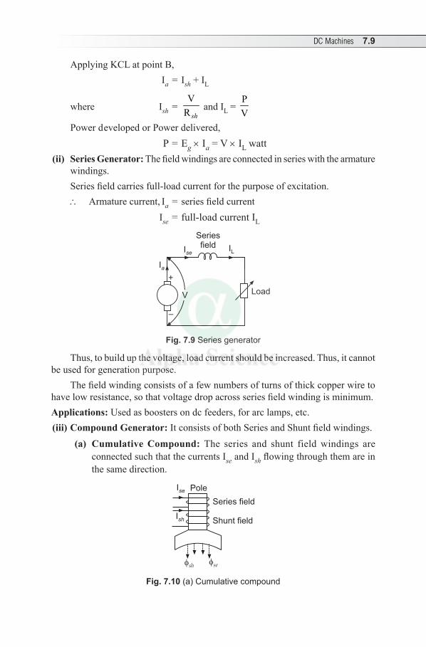
DC Machines 7.9
Applying KCL at point B, Ia = Ish + IL
where Ish = V
R sh and IL =
PV
Power developed or Power delivered, P = Eg × Ia = V × IL watt
(ii) Series Generator: The field windings are connected in series with the armature windings. Series field carries full-load current for the purpose of excitation. \ Armature current, Ia = series field current Ise = full-load current IL
LoadV
Ia
+
–
ILIse
Seriesfield
Fig. 7.9 Series generator
Thus, to build up the voltage, load current should be increased. Thus, it cannot be used for generation purpose.
The field winding consists of a few numbers of turns of thick copper wire to have low resistance, so that voltage drop across series field winding is minimum. Applications: Used as boosters on dc feeders, for arc lamps, etc.(iii) Compound Generator: It consists of both Series and Shunt field windings.
(a) Cumulative Compound: The series and shunt field windings are connected such that the currents Ise and Ish flowing through them are in the same direction.
Ise
Ish
Pole
Series field
Shunt field
se
sh
Fig. 7.10 (a) Cumulative compound
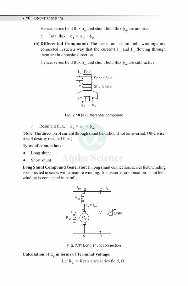
7.10 Electrical Engineering
Hence, series field flux fse and shunt field flux fsh are additive.
\ Total flux, fT = fse + fsh
(b) Differential Compound: The series and shunt field windings are connected in such a way that the currents Ise and Ish flowing through them are in opposite direction.
Hence, series field flux fse and shunt field flux fsh are subtractive.
Ise
Ish
Pole
Series field
Shunt field
se
sh
Fig. 7.10 (a) Differential compound
\ Resultant flux, fR = fse ~ fsh
(Note: The direction of current through shunt field should not be reversed. Otherwise, it will destroy residual flux.)Types of connections:l Long shunt l Short shuntLong Shunt Compound Generator: In long shunt connection, series field winding is connected in series with armature winding. To this series combination shunt field winding is connected in parallel.
Ra
LoadV
Rsh
Rse
+
–
+
–
Ia
= Ise
A D
B CIsh IL
Fig. 7.11 Long shunt connection
Calculation of Eg in terms of Terminal Voltage: Let Rse = Resistance series field, W
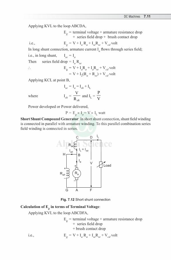
DC Machines 7.11
Applying KVL to the loop ABCDA, Eg = terminal voltage + armature resistance drop + series field drop + brush contact drop i.e., Eg = V + Ia Ra + IseRse + Vcd voltIn long shunt connection, armature current Ia flows through series field;i.e., in long shunt, Ise = Ia
Then series field drop = Ia Rse
\ Eg = V + IaRa + IaRse + Vcd volt = V + I2(Ra + Rse) + Vcd voltApplying KCL at point B, Ise = Ia = Ish + IL
where Ish = V
R sh and IL =
PV
Power developed or Power delivered, P = Eg × Ia = V × IL watt
Short Shunt Compound Generator: In short shunt connection, shunt field winding is connected in parallel with armature winding. To this parallel combination series field winding is connected in series.
Ra
LoadV
Rsh
Rse
+
–
+
–
Ia
AG F
B
D
Ish
IL
IL = Ise
H
C
Fig. 7.12 Short shunt connection
Calculation of Eg in terms of Terminal Voltage: Applying KVL to the loop ABCDFA, Eg = terminal voltage + armature resistance drop + series field drop + brush contact dropi.e., Eg = V + Ia Ra + IseRse + Vcd volt
7.12 Electrical Engineering
In short shunt connection, load current IL flows through series field;i.e., in short shunt, Ise = IL
Then, series field drop = IL Rse \ Eg = V + IaRa + ILRse + Vcd voltApplying KCL at point B, Ia = Ish + IL
Power developed or Power delivered, P = Eg × Ia = V × IL watt
Determination of Ish
Applying KVL to the outer loop GHBCDFAG, Ish Rsh = Ise Rse + V (Neglecting brush contact drop)
or Ish = LV + I R se
shR
and IL = PV
Applications: Cumulative compound generators are used for domestic lighting and to transmit power over a long distance.
Differential compound generator will not find application due to its characteristics. Rarely used for arc welding purpose.
Solved Examples
Example 7.1 A dc shunt generator has an induced voltage on open circuit of 127 volt. When the machine is on load the voltage is 120 V. Find the load current if the field circuit resistance is 15 W and armature resistance is 0.02 W.
Solution: Given: Induced voltage on open circuit, Eg = 127 volt
On load, voltage (terminal), V = 120 volt Rsh = 15 Wand Ra = 0.02 WEMF generated is given by Eg = V + Ia Ra
i.e., 127 = 120 + (Ia × 0.02)
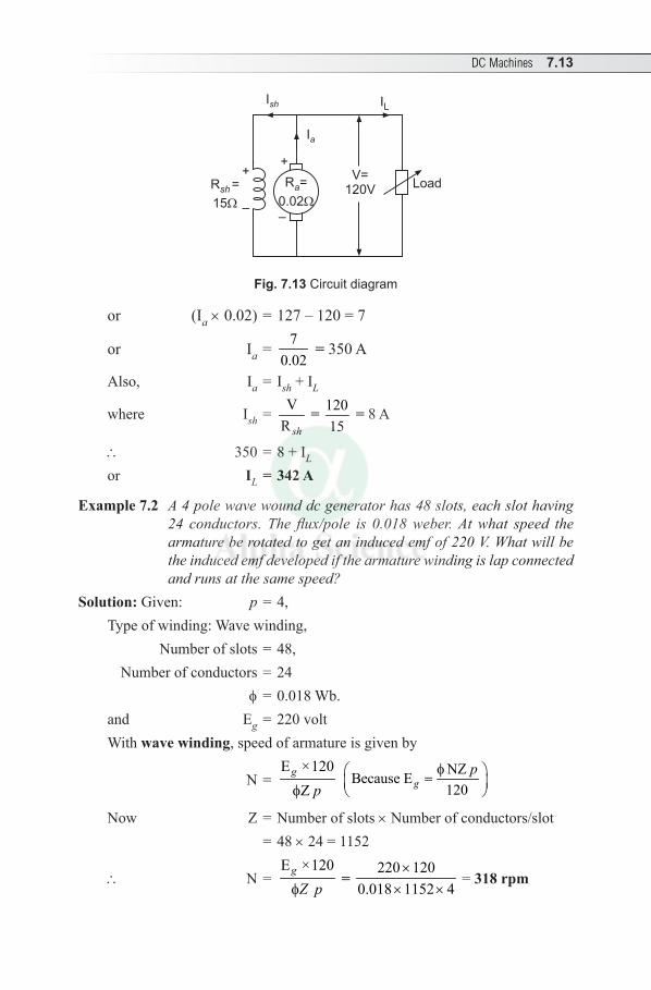
DC Machines 7.13
LoadV=
120VR =
15sh
+
–
Ia
Ish IL
Ra=
0.02
+
–
Fig. 7.13 Circuit diagram
or (Ia × 0.02) = 127 – 120 = 7
or Ia = 70.02
= 350 A
Also, Ia = Ish + IL
where Ish = VR sh
= 12015
= 8 A
\ 350 = 8 + IL
or IL = 342 A
Example 7.2 A 4 pole wave wound dc generator has 48 slots, each slot having 24 conductors. The flux/pole is 0.018 weber. At what speed the armature be rotated to get an induced emf of 220 V. What will be the induced emf developed if the armature winding is lap connected and runs at the same speed?
Solution: Given: p = 4, Type of winding: Wave winding, Number of slots = 48, Number of conductors = 24 f = 0.018 Wb.and Eg = 220 voltWith wave winding, speed of armature is given by
N = E ×120
Zg
pf
NZBecause E120g
pf =
Now Z = Number of slots × Number of conductors/slot = 48 × 24 = 1152
\ N = E ×120g
Z pf =
220 1200.018 1152 4
×× ×
= 318 rpm
7.14 Electrical Engineering
When armature is lap connected, induced emf is
Eg = NZ 0.018 318 1152 109.9 V 110 V60 60
f × ×= = ≈
Example 7.3 A 4 pole generator has 36 slots with 10 conductors/slot. The flux and speed are such that an average emf generated in each conductor is 1.7 volts. The current in each parallel path is 10A. Determine the total power generated when the armature winding is i) lap connected and ii) wave connected.
Solution: Given: p = 4 Number of slots = 36 Number of conductors = 10
emf/conductor = 1.7 volt Current/parallel Ia/A = 10A Power generated, P = Eg × I watt
(i) For lap winding, A = P = 4
No. of conductors/parallel path = Z 36 10 90A 4
×= =
Eg = emf/conductor × No. of conductors/parallel path = 1.7 × 90 = 153 VCurrent, I = Current/parallel path × No. of parallel paths = 10 × 4 = 40 A\ P = 153 × 40 = 6120 W = 6.12 kW
(ii) For wave winding, A = 2
No. of conductors/parallel path = Z 36 10 180A 2
×= =
Eg = emf/conductor × No. of conductors/parallel path = 1.7 × 180 = 306 V Current, I = Current/parallel path × No. of parallel paths = 10 × 2 = 20A \ P = 306 × 20 = 6120 W = 6.12 kW
Example 7.4 A 4 pole wave wound shunt generator delivers 200 A at a terminal voltage of 250 V. Ra and Rsh are 0.05 W and 50 W respectively. Neglecting brush drop, determine (i) Ia, (ii) current per parallel path, (iii) Eg and (iv) Power developed.
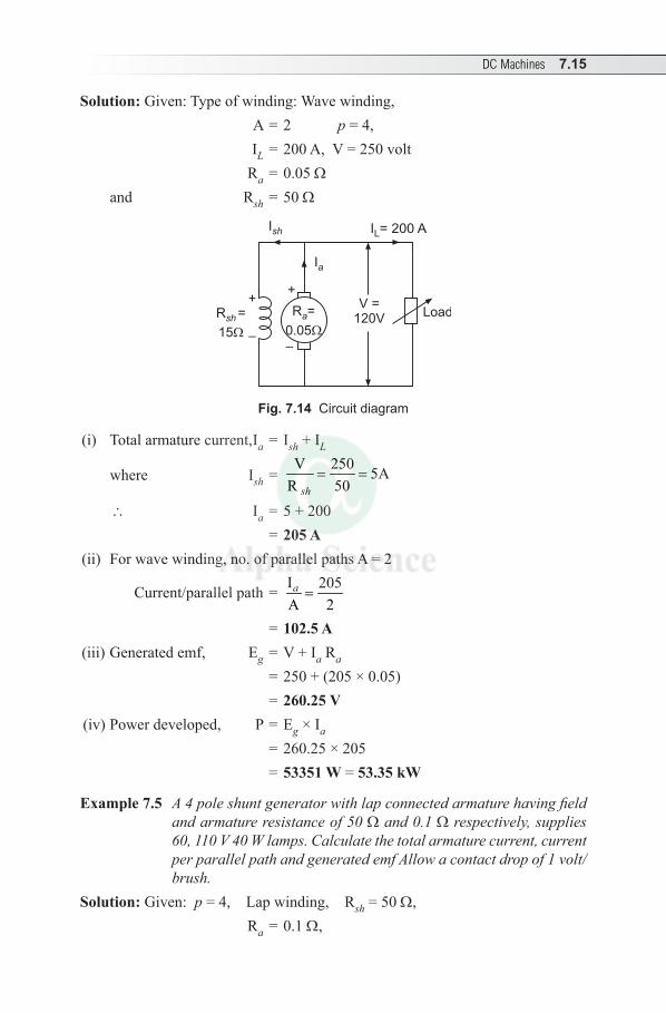
DC Machines 7.15
Solution: Given: Type of winding: Wave winding, A = 2 p = 4, IL = 200 A, V = 250 volt
Ra = 0.05 Wand Rsh = 50 W
LoadV =
120VR =
15sh
+
–
Ia
Ish IL= 200 A
Ra=
0.05
+
–
Fig. 7.14 Circuit diagram
(i) Total armature current, Ia = Ish + IL
where Ish = V 250 5A
R 50sh= =
\ Ia = 5 + 200 = 205 A
(ii) For wave winding, no. of parallel paths A = 2
Current/parallel path = I 205A 2a =
= 102.5 A(iii) Generated emf, Eg = V + Ia Ra
= 250 + (205 × 0.05) = 260.25 V (iv) Power developed, P = Eg × Ia = 260.25 × 205 = 53351 W = 53.35 kW
Example 7.5 A 4 pole shunt generator with lap connected armature having field and armature resistance of 50 W and 0.1 W respectively, supplies 60, 110 V 40 W lamps. Calculate the total armature current, current per parallel path and generated emf Allow a contact drop of 1 volt/ brush.
Solution: Given: p = 4, Lap winding, Rsh = 50 W, Ra = 0.1 W,
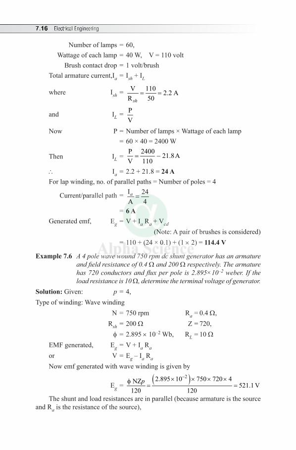
7.16 Electrical Engineering
Number of lamps = 60, Wattage of each lamp = 40 W, V = 110 volt Brush contact drop = 1 volt/brush Total armature current, Ia = Ish + IL
where Ish = V 110 2.2 AR 50sh
= =
and IL = PV
Now P = Number of lamps × Wattage of each lamp = 60 × 40 = 2400 W
Then IL = P 2400 21.8AV 110
= -
\ Ia = 2.2 + 21.8 = 24 AFor lap winding, no. of parallel paths = Number of poles = 4
Current/parallel path = I 24A 4a =
= 6 AGenerated emf, Eg = V + Ia Ra + Vcd
(Note: A pair of brushes is considered) = 110 + (24 × 0.1) + (1 × 2) = 114.4 V
Example 7.6 A 4 pole wave wound 750 rpm dc shunt generator has an armature and field resistance of 0.4 W and 200 W respectively. The armature has 720 conductors and flux per pole is 2.895×10⁻² weber. If the load resistance is 10 W, determine the terminal voltage of generator.
Solution: Given: p = 4, Type of winding: Wave winding
N = 750 rpm Ra = 0.4 W, Rsh = 200 W Z = 720, f = 2.895 × 10⁻² Wb, RL = 10 W EMF generated, Eg = V + Ia Ra or V = Eg – Ia Ra
Now emf generated with wave winding is given by
Eg = ( )22.895 10 750 720 4NZ 521.1 V
120 120p
-× × × ×f= =
The shunt and load resistances are in parallel (because armature is the source and Ra is the resistance of the source),
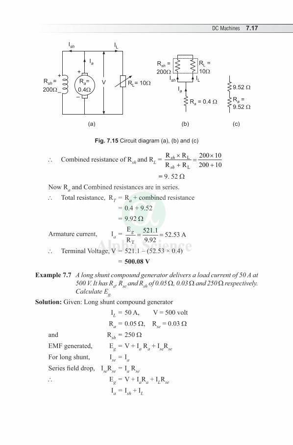
DC Machines 7.17
RL= 10VR =
200sh
+
–
Ia
Ish IL
Ra=
0.4
+
–
9.52
R =
9.52a
ILIsh
R =
10L
R =
200sh
Ia
R = 0.4a
(a) (b) (c)
Fig. 7.15 Circuit diagram (a), (b) and (c)
\ Combined resistance of Rsh and RL = L
L
R R 200 10R R 200 10
sh
sh
× ×=
+ +
= 9. 52 W Now Ra and Combined resistances are in series. \ Total resistance, RT = Ra + combined resistance = 0.4 + 9.52 = 9.92 W
Armature current, Ia = T
E 521.1 52.53 AR 9.92
g = =
\ Terminal Voltage, V = 521.1 – (52.53 × 0.4) = 500.08 V
Example 7.7 A long shunt compound generator delivers a load current of 50 A at 500 V. It has Ra, Rse and Rsh of 0.05 W, 0.03 W and 250 W respectively. Calculate Eg.
Solution: Given: Long shunt compound generator IL = 50 A, V = 500 volt Ra = 0.05 W, Rse = 0.03 Wand Rsh = 250 WEMF generated, Eg = V + Ia Ra + IseRse
For long shunt, Ise = Ia
Series field drop, IseRse = Ia Rse
\ Eg = V + IaRa + ILRse Ia = Ish + I L
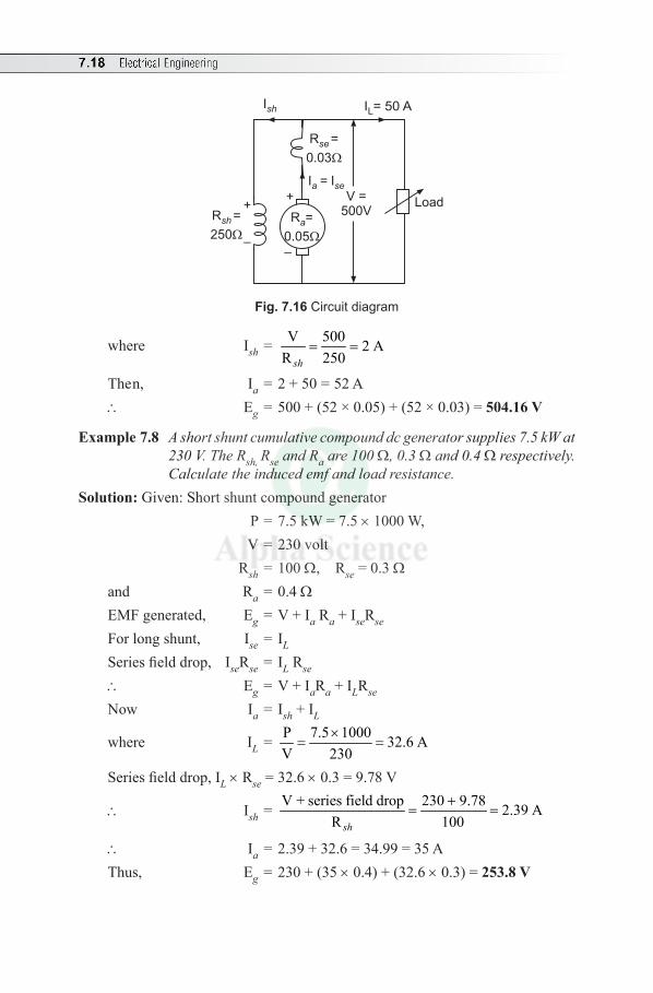
7.18 Electrical Engineering
LoadV =500VR =
250sh
+
–
Ia
= Ise
Ish IL= 50 A
Ra=
0.05
+
–
R =
0.03se
Fig. 7.16 Circuit diagram
where Ish = V 500 2 AR 250sh
= =
Then, Ia = 2 + 50 = 52 A\ Eg = 500 + (52 × 0.05) + (52 × 0.03) = 504.16 V
Example 7.8 A short shunt cumulative compound dc generator supplies 7.5 kW at 230 V. The Rsh, Rse and Ra are 100 W, 0.3 W and 0.4 W respectively. Calculate the induced emf and load resistance.
Solution: Given: Short shunt compound generator P = 7.5 kW = 7.5 × 1000 W, V = 230 volt Rsh = 100 W, Rse = 0.3 Wand Ra = 0.4 WEMF generated, Eg = V + Ia Ra + IseRse
For long shunt, Ise = IL
Series field drop, IseRse = IL Rse \ Eg = V + IaRa + ILRse Now Ia = Ish + I L
where IL = P 7.5 1000 32.6 AV 230
×= =
Series field drop, IL × Rse = 32.6 × 0.3 = 9.78 V
\ Ish = V + series field drop 230 9.78 2.39 A
R 100sh
+= =
\ Ia = 2.39 + 32.6 = 34.99 = 35 A Thus, Eg = 230 + (35 × 0.4) + (32.6 × 0.3) = 253.8 V
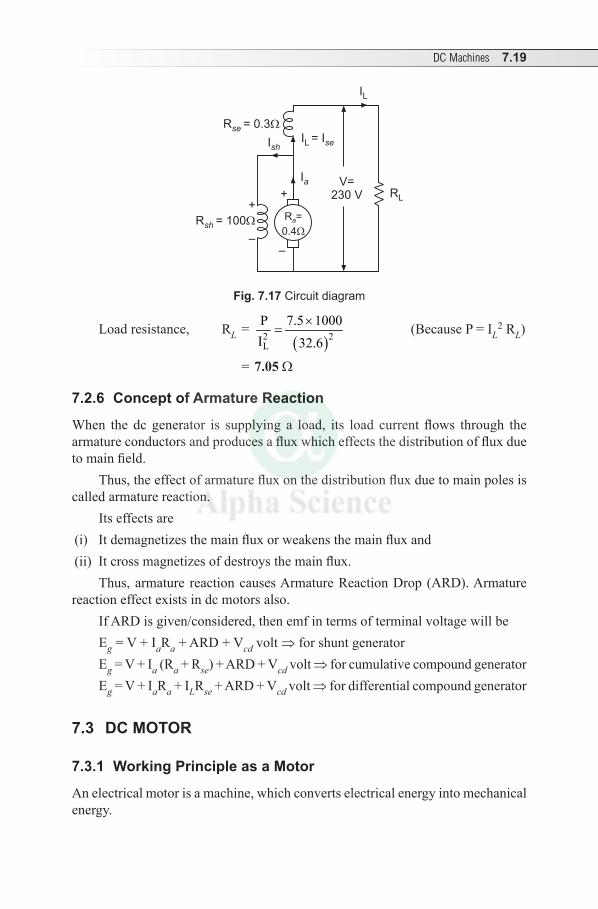
DC Machines 7.19
V=230 V
Rsh
= 100
Rse
= 0.3
+
–
+
–
Ia
Ish
IL
IL = Ise
RL
Ra=
0.4
Fig. 7.17 Circuit diagram
Load resistance, RL = ( )2 2
L
P 7.5 1000I 32.6
×= (Because P = IL
2 RL)
= 7.05 W
7.2.6 Concept of Armature Reaction
When the dc generator is supplying a load, its load current flows through the armature conductors and produces a flux which effects the distribution of flux due to main field.
Thus, the effect of armature flux on the distribution flux due to main poles is called armature reaction.
Its effects are (i) It demagnetizes the main flux or weakens the main flux and (ii) It cross magnetizes of destroys the main flux.
Thus, armature reaction causes Armature Reaction Drop (ARD). Armature reaction effect exists in dc motors also.
If ARD is given/considered, then emf in terms of terminal voltage will beEg = V + IaRa + ARD + Vcd volt ⇒ for shunt generatorEg = V + Ia (Ra + Rse) + ARD + Vcd volt ⇒ for cumulative compound generatorEg = V + IaRa + ILRse + ARD + Vcd volt ⇒ for differential compound generator
7.3 DC MOTOR
7.3.1 Working Principle as a Motor
An electrical motor is a machine, which converts electrical energy into mechanical energy.
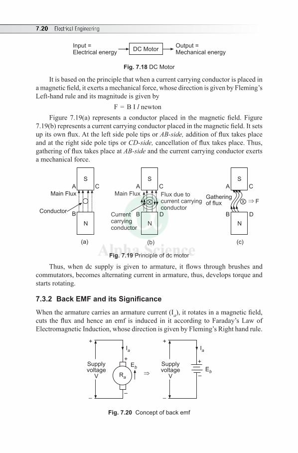
7.20 Electrical Engineering
Input =Electrical energy
Output =Mechanical energy
DC Motor
Fig. 7.18 DC Motor
It is based on the principle that when a current carrying conductor is placed in a magnetic field, it exerts a mechanical force, whose direction is given by Fleming’s Left-hand rule and its magnitude is given by
F = B I l newton Figure 7.19(a) represents a conductor placed in the magnetic field. Figure
7.19(b) represents a current carrying conductor placed in the magnetic field. It sets up its own flux. At the left side pole tips or AB-side, addition of flux takes place and at the right side pole tips or CD-side, cancellation of flux takes place. Thus, gathering of flux takes place at AB-side and the current carrying conductor exerts a mechanical force.
Main Flux
Conductor
N
S
A C
B
Main Flux
Currentcarryingconductor
N
S
A C
B D
Flux due tocurrent carryingconductor
X
N
S
A C
B D
X FGatheringof flux
(a) (b) (c)
Fig. 7.19 Principle of dc motor
Thus, when dc supply is given to armature, it flows through brushes and commutators, becomes alternating current in armature, thus, develops torque and starts rotating.
7.3.2 Back EMFanditsSignificance
When the armature carries an armature current (Ia), it rotates in a magnetic field, cuts the flux and hence an emf is induced in it according to Faraday’s Law of Electromagnetic Induction, whose direction is given by Fleming’s Right hand rule.
Supplyvoltage
V
+
–
Ia
+
–
Ra
Eb
Supplyvoltage
V
+
–
Ia
+
–E
b
Fig. 7.20 Concept of back emf
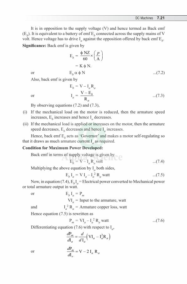
DC Machines 7.21
It is in opposition to the supply voltage (V) and hence termed as Back emf (Eb). It is equivalent to a battery of emf Eb connected across the supply mains of V volt. Hence voltage has to drive Ia against the opposition offered by back emf Eb.Significance: Back emf is given by
Eb = NZ60 A
pf ×
= K f N.or Eb a f N ...(7.2) Also, back emf is given by Eb = V - Ia Ra
or Ia = V – ER
b
a ...(7.3)
By observing equations (7.2) and (7.3),(i) If the mechanical load on the motor is reduced, then the armature speed
increases, Eb increases and hence Ia decreases.(ii) If the mechanical load is applied or increases on the motor, then the armature
speed decreases, Eb decreases and hence Ia increases. Hence, back emf Eb acts as ‘Governor’ and makes a motor self-regulating so
that it draws as much armature current Ia as required. Condition for Maximum Power Developed:
Back emf in terms of supply voltage is given by Eb = V – Ia Ra volt ...(7.4) Multiplying the above equation by Ia both sides, Eb Ia = V Ia – Ia
2 Ra watt ...(7.5)Now, in equation (7.4), Eb Ia = Electrical power converted to Mechanical power
or total armature output in watt. or Eb Ia = Pm VIa = Input to the armature, wattand Ia
2 Ra = Armature copper loss, watt Hence equation (7.5) is rewritten as Pm = VIa – Ia
2 Ra watt ...(7.6)Differentiating equation (7.6) with respect to Ia,
( )2PVI – I R
I Im
a a aa a
d dd d
=
or PV – 2 I R
Im
a aa
dd
=
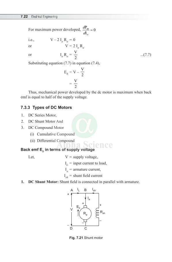
7.22 Electrical Engineering
For maximum power developed, P0
Im
a
dd
=
i.e., V – 2 Ia Ra = 0or V = 2 Ia Ra
or I a Ra = V2
...(7.7)
Substituting equation (7.7) in equation (7.4),
Eb = V – V2
= V2
Thus, mechanical power developed by the dc motor is maximum when back emf is equal to half of the supply voltage.
7.3.3 Types of DC Motors
1. DC Series Motor,2. DC Shunt Motor And 3. DC Compound Motor
(i) Cumulative Compound(ii) Differential Compound
Back emf Eb in terms of supply voltage
Let, V = supply voltage, IL = input current to load, Ia = armature current, Ish = shunt field current
1. DC Shunt Motor: Shunt field is connected in parallel with armature.
Ra
A IL IshB
V
D C
Rsh
Eb+
–
Ia
+
–
+
–
Fig. 7.21 Shunt motor
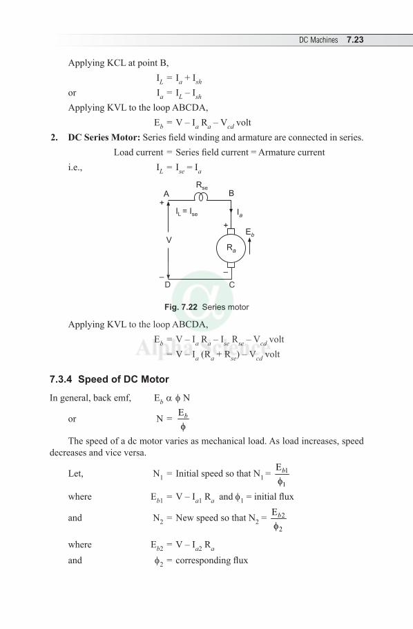
DC Machines 7.23
Applying KCL at point B, IL = Ia + Ish
or Ia = IL – Ish Applying KVL to the loop ABCDA, Eb = V – Ia Ra – Vcd volt
2. DC Series Motor: Series field winding and armature are connected in series. Load current = Series field current = Armature currenti.e., IL = Ise = Ia
Ra
Eb
Ia
A B
V
D C
Rse
I =L Ise
+
–
+
–
Fig. 7.22 Series motor
Applying KVL to the loop ABCDA, Eb = V – Ia Ra – Ise Rse – Vcd volt = V – Ia (Ra + Rse) – Vcd volt
7.3.4 Speed of DC Motor
In general, back emf, Eb a f N
or N = Eb
fThe speed of a dc motor varies as mechanical load. As load increases, speed
decreases and vice versa.
Let, N1 = Initial speed so that N1 = 1
1
Eb
f
where Eb1 = V – Ia1 Ra and f1 = initial flux
and N2 = New speed so that N2 = 2
2
Eb
f
where Eb2 = V – Ia2 Ra and f2 = corresponding flux
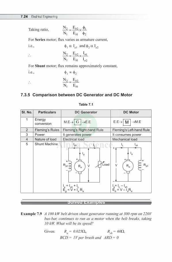
7.24 Electrical Engineering
Taking ratio, 22 1
1 1 2
ENN E
b
b
f= ×
f
For Series motor; flux varies as armature current,i.e., f1 a Ia1 and f2 a Ia2
\ 22 1
1 1 2
IENN E I
ab
b a= ×
For Shunt motor; flux remains approximately constant, i.e., f1 ≈ f2
\ 22
1 1
ENN E
b
b=
7.3.5 Comparison between DC Generator and DC Motor
Table 7.1
SI. No. Particulars DC Generator DC Motor
1 Energy conversion M.E→ G →E.E E.E→ M →M.E
2 Fleming’s Rules Fleming’s Right-hand Rule Fleming’s Left-hand Rule3 Power It generates power It consumes power4 Nature of load Electrical load Mechanical load5 Shunt Machine
LoadVRsh
+
–
Ia
Ish IL
Ra
+
–
Ia = Ish + ILEg = V + Ia Ra
V Rsh
+
–
Ia
Ish
Ra
+
–
+
–
IL
Ia= IL – IshEb = V – IaRa
Solved Examples
Example 7.9 A 100 kW belt driven shunt generator running at 300 rpm on 220V bus-bar, continues to run as a motor when the belt breaks, taking 10 kW. What will be its speed?
Given: Ra = 0.025W, Rsh = 60W, BCD = 1V per brush and ARD = 0
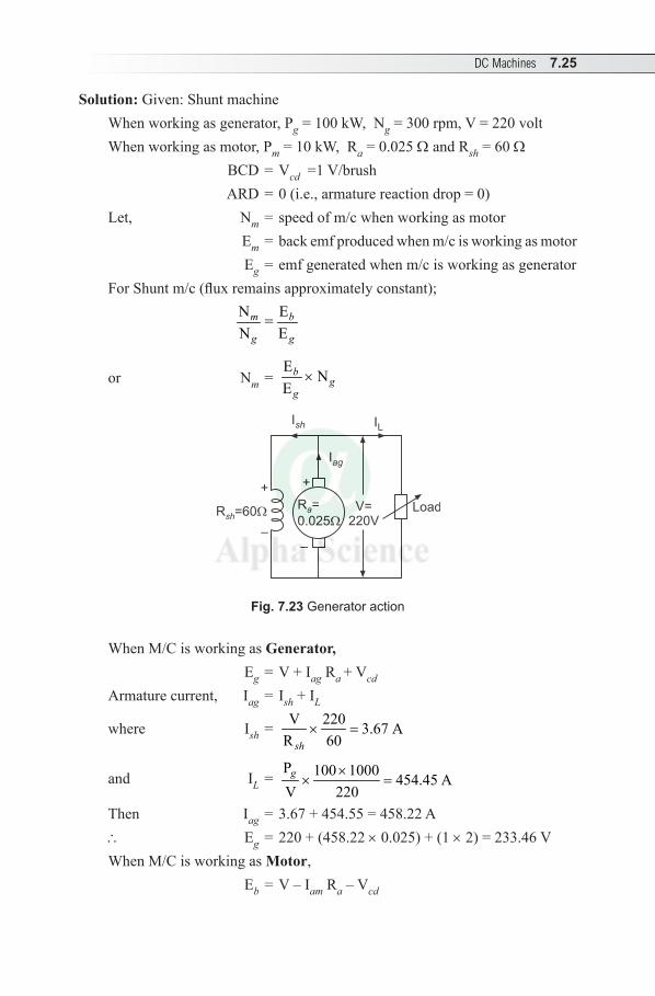
DC Machines 7.25
Solution: Given: Shunt machine When working as generator, Pg = 100 kW, Ng = 300 rpm, V = 220 volt When working as motor, Pm = 10 kW, Ra = 0.025 W and Rsh = 60 W BCD = Vcd = 1 V/brush ARD = 0 (i.e., armature reaction drop = 0)Let, Nm = speed of m/c when working as motor Em = back emf produced when m/c is working as motor Eg = emf generated when m/c is working as generator For Shunt m/c (flux remains approximately constant);
N E=N E
m b
g g
or Nm = E NE
bg
g×
Load
+
–
Iag
Ish IL
+
–
V=220V
R =
0.025a
R =60sh
Fig. 7.23 Generator action
When M/C is working as Generator, Eg = V + Iag Ra + Vcd
Armature current, Iag = Ish + IL
where Ish = V 220 3.67 AR 60sh
× =
and IL = P 100 1000 454.45 AV 220
g ×× =
Then Iag = 3.67 + 454.55 = 458.22 A\ Eg = 220 + (458.22 × 0.025) + (1 × 2) = 233.46 VWhen M/C is working as Motor, Eb = V – Iam Ra – Vcd
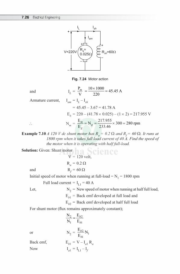
7.26 Electrical Engineering
+
–
Iam
Ish
+
–
+
–
IL
R =60sh
R =
0.025a
V=220V
Fig. 7.24 Motor action
and IL = P 10 1000 45.45 AV 220m ×
= =
Armature current, Iam = IL – Ish
= 45.45 – 3.67 = 41.78 A Eb = 220 – (41.78 × 0.025) – (1 × 2) = 217.955 V
\ Nm = E 217.955N 300 280 rpmE 233.46
mg
g= = × =
Example 7.10 A 120 V dc shunt motor has Ra = 0.2 W and Rf = 60 W. It runs at 1800 rpm when it takes full load current of 40 A. Find the speed of the motor when it is operating with half full-load.
Solution: Given: Shunt motor V = 120 volt, Ra = 0.2 Wand Rf = 60 W Initial speed of motor when running at full-load = N1 = 1800 rpm Full load current = IL1 = 40 ALet, N2 = New speed of motor when running at half full load, Eb1 = Back emf developed at full load and Eb2 = Back emf developed at half full loadFor shunt motor (flux remains approximately constant);
22
1 1
ENN E
b
b=
or N2 = 21
1
E NE
b
b
Back emf, Eb1 = V – Ia1 Ra
Now Ia1 = IL1 – If
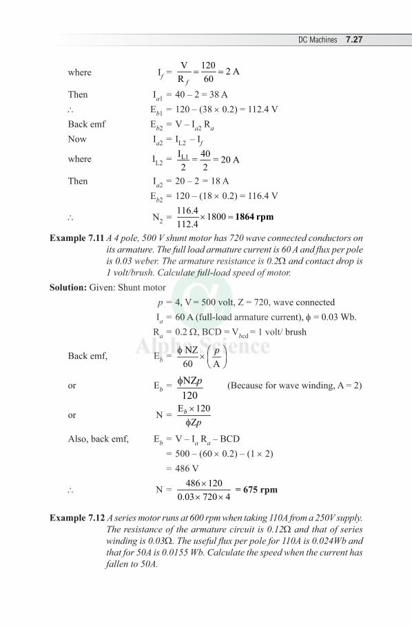
DC Machines 7.27
where If = V 120 2 A
R 60f= =
Then Ia1 = 40 – 2 = 38 A\ Eb1 = 120 – (38 × 0.2) = 112.4 VBack emf Eb2 = V – Ia2 Ra
Now Ia2 = IL2 – If
where IL2 = L1I 40= = 20 A2 2
Then Ia2 = 20 – 2 = 18 A Eb2 = 120 – (18 × 0.2) = 116.4 V
\ N2 = 116.4 1800112.4
× = 1864 rpm
Example 7.11 A 4 pole, 500 V shunt motor has 720 wave connected conductors on its armature. The full load armature current is 60 A and flux per pole is 0.03 weber. The armature resistance is 0.2W and contact drop is 1 volt/brush. Calculate full-load speed of motor.
Solution: Given: Shunt motor p = 4, V = 500 volt, Z = 720, wave connected Ia = 60 A (full-load armature current), f = 0.03 Wb. Ra = 0.2 W, BCD = Vbcd = 1 volt/ brush
Back emf, Eb = NZ60 A
pf ×
or Eb = NZ120
pf (Because for wave winding, A = 2)
or N = E 120
Zb
p×
f
Also, back emf, Eb = V – Ia Ra – BCD = 500 – (60 × 0.2) – (1 × 2) = 486 V
\ N = 486 120
0.03 720 4×
× × = 675 rpm
Example 7.12 A series motor runs at 600 rpm when taking 110A from a 250V supply. The resistance of the armature circuit is 0.12W and that of series winding is 0.03W. The useful flux per pole for 110A is 0.024Wb and that for 50A is 0.0155 Wb. Calculate the speed when the current has fallen to 50A.
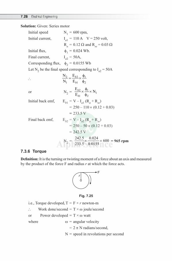
7.28 Electrical Engineering
Solution: Given: Series motorInitial speed N1 = 600 rpm, Initial current, Ia1 = 110 A V = 250 volt, Ra = 0.12 W and Rse = 0.03 W Initial flux, f1 = 0.024 Wb.Final current, Ia2 = 50A, Corresponding flux, f2 = 0.0155 Wb Let N2 be the final speed corresponding to Ia2 = 50A
\ 22 1
1 1 2
ENN E
b
b
f= ×
f
or N2 = 2 11
1 2
E NE
b
b
f× ×
f
Initial back emf, Eb1 = V – Ia1 (Ra + Rse) = 250 – 110 × (0.12 + 0.03) = 233.5 V Final back emf, Eb2 = V – Ia2 (Ra + Rse) = 250 – 50 × (0.12 + 0.03) = 242.5 V
N2 = 242.5 0.024 600233.5 0.0155
× × = 965 rpm
7.3.6 Torque
Definition: It is the turning or twisting moment of a force about an axis and measured by the product of the force F and radius r at which the force acts.
r
F
Fig. 7.25
i.e., Torque developed, T = F × r newton-m \ Work done/second = T × w joule/secondor Power developed = T × w wattwhere w = angular velocity = 2 p N radians/second, N = speed in revolutions per second
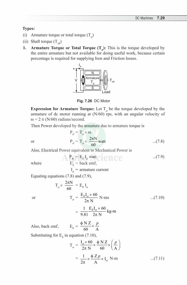
DC Machines 7.29
Types:(i) Armature torque or total torque (Ta) (ii) Shaft torque (Tsh)1. Armature Torque or Total Torque (Ta): This is the torque developed by
the entire armature but not available for doing useful work, because certain percentage is required for supplying Iron and Friction losses.
S
N+
–
V
Load
Ia
Ta
ArmatureT
sh
Fig. 7.26 DC Motor
Expression for Armature Torque: Let Ta be the torque developed by the armature of dc motor running at (N/60) rps, with an angular velocity of w = 2 p (N/60) radians/second.Then Power developed by the armature due to armature torque is Pd = Ta × w
or Pd = Ta × 2 N watt60p ...(7.8)
Also, Electrical Power equivalent to Mechanical Power is Pm = Eb Ia watt ...(7.9)where Eb = back emf, Ia = armature currentEquating equations (7.8) and (7.9),
Ta × 2 N60p = Eb Ia
or Ta = E I 60
2 Nb a ×
p N-ms ...(7.10)
= E I 601 kg-m
9.81 2 Nb a ×
p
Also, back emf, Eb = N Z60 A
pf×
Substituting for Eb in equation (7.10),
Ta = I 60 N Z2 N 60 Aa p× f × × p
= 1 Z I2 A a
pf× ×
p N-m ...(7.11)
7.30 Electrical Engineering
or Ta = K f Ia where K = 1 Z
2 Ap
×p
or Ta ∝ f Ia
Hence, total or armature torque developed is directly proportional to the product of flux/pole and armature current.
For series motor, f ∝ Ia
Ta ∝ Ia2
For shunt motor, f remains approximately constant and therefore, Ta ∝ Ia
2. Shaft Torque (Tsh): This is available at the shaft for doing the useful work and hence also called Useful Torque.
Expression for Shaft Torque: The power obtained due to shaft torque is called as BHP (Brake Horse Power).
[Note: 1 HP = 735.49875 W = ≈ 735.5 W (metric) and 747 W (British).]
Now, Output of Motor = Tsh × 2 N60p watt
or Tsh = ( )Output of Motor in watt
2 N/60p N-m
or Tsh = ( )BHP 735.5
2 N/60×
p N-m ...(7.12)
If Tf = Torque due to Iron and Friction loss,
Then Tf = ( )Iron and Friction loss in watt
2 N/60p
Then Tsh = Ta – Tf ...(7.13)
\ Lost torque, Ta – Tsh = ( )
Rotational losses watt2 N/60p
...(7.14)
Solved Examples
Example 7.13 A 4 pole, 220 V lap connected dc shunt motor has 36 slots, each containing 16 conductors. It draws a current of 40 A from the supply. The field resistance and armature resistance are 110 W and 0.1 W respectively. The motor develops an output power of 6 kW. The flux per pole is 40 mWb. Calculate (a) the speed (b) torque developed by the armature and (c) the shaft torque.
Solution: Given: Shunt motorp = 4, V = 220 volt, lap connection, No. of slots = 36, conductors/slot = 16,
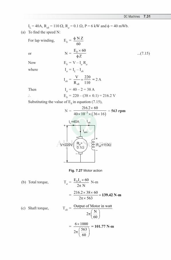
DC Machines 7.31
IL = 40A, Rsh = 110 W, Ra = 0.1 W, P = 6 kW and f = 40 mWb.(a) To find the speed N:
For lap winding, Eb = N Z60
f
or N = E 60
Z b ×f
...(7.15)
Now Eb = V – Ia Ra
where Ia = IL – Ish
Ish = V 220R 110sh
= = 2 A
Then Ia = 40 – 2 = 38 A \ Eb = 220 – (38 × 0.1) = 216.2 V Substituting the value of Eb in equation (7.15),
N = ( )–3
216.2 6040 10 36 16
×× × ×
= 563 rpm
+
–
Iam
Ish
+
–
+
–
IL=40A
R =110sh
R =
0.1a
V=220V
Fig. 7.27 Motor action
(b) Total torque, Ta = E I 602 N
b a ×p
N-m
= 216.2 38 60 -
2 563× ×
=p ×
139.42 N m
(c) Shaft torque, Tsh = Output of Motor in wattN260
p
= 6 1000563260
× p
= 101.77 N-m
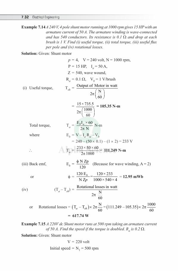
7.32 Electrical Engineering
Example 7.14 A 240 V, 4 pole shunt motor running at 1000 rpm gives 15 HP with an armature current of 50 A. The armature winding is wave-connected and has 540 conductors. Its resistance is 0.1 W and drop at each brush is 1 V. Find (i) useful torque, (ii) total torque, (iii) useful flux per pole and (iv) rotational losses.
Solution: Given: Shunt motor p = 4, V = 240 volt, N = 1000 rpm, P = 15 HP, Ia = 50 A, Z = 540, wave wound, Ra = 0.1 W, Vb = 1 V/brush
(i) Useful torque, Tsh = Output of Motor in wattN260
p
= 15 × 735.510002
60 p
= 105.35 N-m
Total torque, Ta = E I × 602 N
b a
p N-m
where Eb = V – Ia Ra – Vb = 240 – (50 × 0.1) – (1 × 2) = 233 V
\ Ta = 233× 50 × 60 =2 1000p
111.249 N-m
(iii) Back emf, Eb = N Zp120
f (Because for wave winding, A = 2)
or f = 120 E 120 × 233 =
N Z 1000 × 540 × 4b
p = 12.95 mWb
(iv) (Ta – Tsh) = Rotational losses in wattN2 60
p
or Rotational losses = ( ) ( )N 1000T – T 2 = 111.249 – 105.35 260 60a sh × p × p
= 617.74 W
Example 7.15 A 220V dc Shunt motor runs at 500 rpm taking an armature current of 50 A. Find the speed if the torque is doubled. Ra is 0.2 W.
Solution: Given: Shunt motor V = 220 volt Initial speed = N1 = 500 rpm
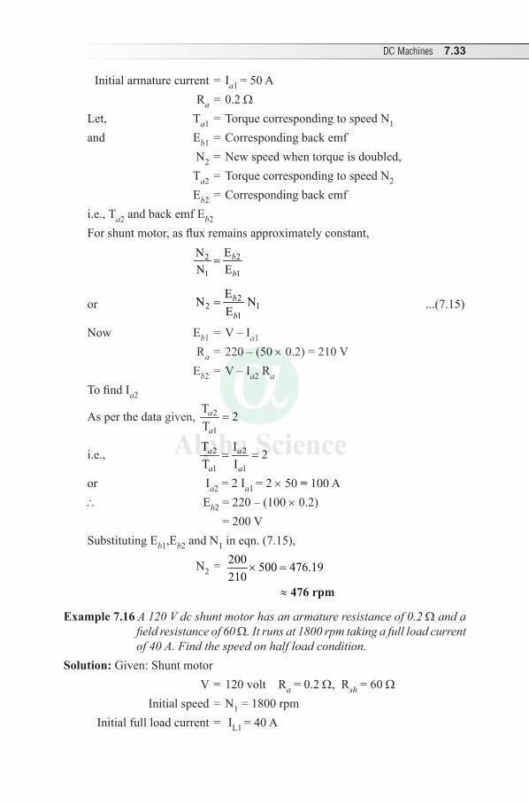
DC Machines 7.33
Initial armature current = Ia1 = 50 A Ra = 0.2 WLet, Ta1 = Torque corresponding to speed N1
and Eb1 = Corresponding back emf N2 = New speed when torque is doubled, Ta2 = Torque corresponding to speed N2
Eb2 = Corresponding back emfi.e., Ta2 and back emf Eb2
For shunt motor, as flux remains approximately constant,
22
1 1
ENN E
b
b=
or 22 1
1
EN NE
b
b= ...(7.15)
Now Eb1 = V – Ia1
Ra = 220 – (50 × 0.2) = 210 V Eb2 = V – Ia2 Ra
To find Ia2
As per the data given, 2
1
T 2T
a
a=
i.e., 2 2
1 1
T I 2T I
a a
a a= =
or Ia2 = 2 Ia1 = 2 × 50 = 100 A\ Eb2 = 220 – (100 × 0.2) = 200 VSubstituting Eb1,Eb2 and N1 in eqn. (7.15),
N2 = 200 500 476.19210
× =
≈ 476 rpm
Example 7.16 A 120 V dc shunt motor has an armature resistance of 0.2 W and a field resistance of 60 W. It runs at 1800 rpm taking a full load current of 40 A. Find the speed on half load condition.
Solution: Given: Shunt motor V = 120 volt Ra = 0.2 W, Rsh = 60 W Initial speed = N1 = 1800 rpm Initial full load current = IL1 = 40 A
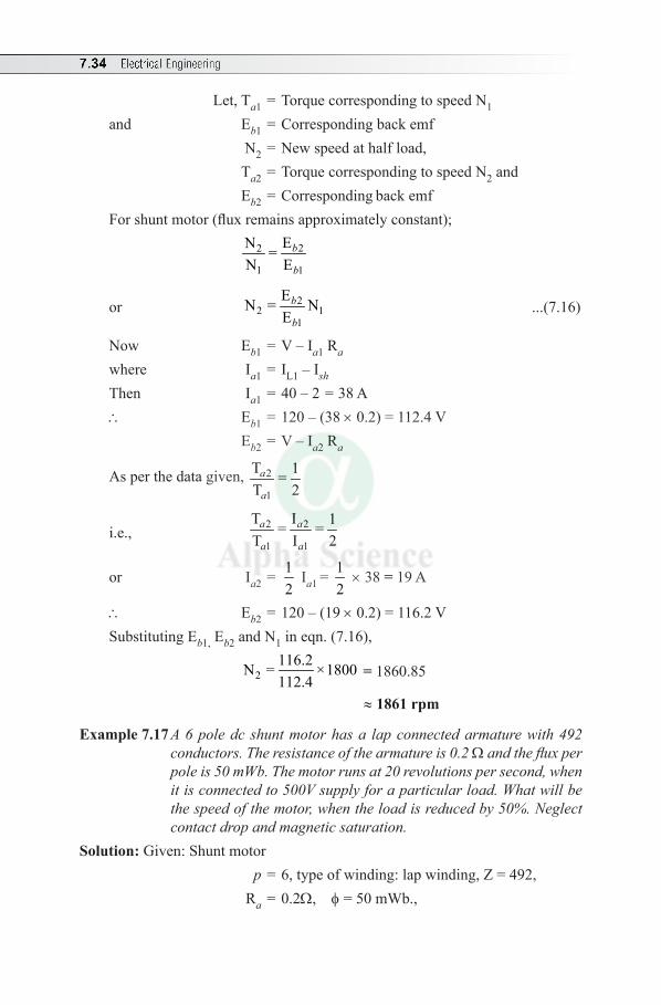
7.34 Electrical Engineering
Let, Ta1 = Torque corresponding to speed N1
and Eb1 = Corresponding back emf N2 = New speed at half load, Ta2 = Torque corresponding to speed N2 and Eb2 = Corresponding back emf For shunt motor (flux remains approximately constant);
22
1 1
EN =N E
b
b
or 22 1
1
EN = NE
b
b ...(7.16)
Now Eb1 = V – Ia1 Ra
where Ia1 = IL1 – I sh
Then Ia1 = 40 – 2 = 38 A\ Eb1 = 120 – (38 × 0.2) = 112.4 V Eb2 = V – Ia2 Ra
As per the data given, 2
1
T 1=T 2
a
a
i.e., 2 2
1 1
T I 1= =T I 2
a a
a a
or Ia2 = 12
Ia1 = 12
× 38 = 19 A
\ Eb2 = 120 – (19 × 0.2) = 116.2 VSubstituting Eb1, Eb2 and N1 in eqn. (7.16),
2116.2N = ×1800112.4
= 1860.85
≈ 1861 rpm
Example 7.17 A 6 pole dc shunt motor has a lap connected armature with 492 conductors. The resistance of the armature is 0.2 W and the flux per pole is 50 mWb. The motor runs at 20 revolutions per second, when it is connected to 500V supply for a particular load. What will be the speed of the motor, when the load is reduced by 50%. Neglect contact drop and magnetic saturation.
Solution: Given: Shunt motor p = 6, type of winding: lap winding, Z = 492, Ra = 0.2W, f = 50 mWb.,
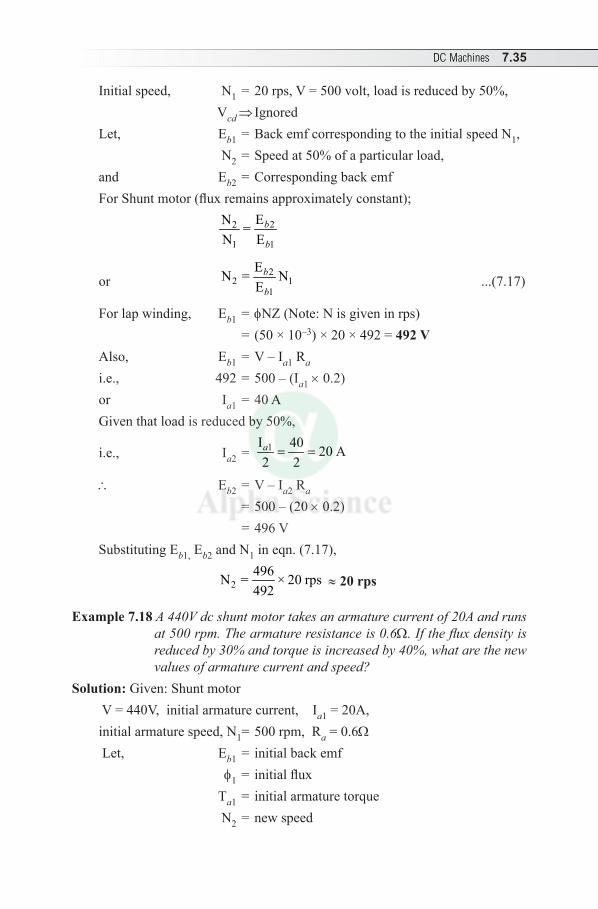
DC Machines 7.35
Initial speed, N1 = 20 rps, V = 500 volt, load is reduced by 50%, Vcd ⇒ IgnoredLet, Eb1 = Back emf corresponding to the initial speed N1, N2 = Speed at 50% of a particular load,and Eb2 = Corresponding back emfFor Shunt motor (flux remains approximately constant);
22
1 1
EN =N E
b
b
or 2
2 11
EN = NE
b
b ...(7.17)
For lap winding, Eb1 = fNZ (Note: N is given in rps) = (50 × 10–3) × 20 × 492 = 492 VAlso, Eb1 = V – Ia1 Ra
i.e., 492 = 500 – (Ia1 × 0.2)or Ia1 = 40 AGiven that load is reduced by 50%,
i.e., Ia2 = 1I 40 20 A2 2a = =
\ Eb2 = V – Ia2 Ra
= 500 – (20 × 0.2) = 496 VSubstituting Eb1, Eb2 and N1 in eqn. (7.17),
2496N = × 20 rps492
≈ 20 rps
Example 7.18 A 440V dc shunt motor takes an armature current of 20A and runs at 500 rpm. The armature resistance is 0.6W. If the flux density is reduced by 30% and torque is increased by 40%, what are the new values of armature current and speed?
Solution: Given: Shunt motor V = 440V, initial armature current, Ia1 = 20A, initial armature speed, N1 = 500 rpm, Ra = 0.6W
Let, Eb1 = initial back emf f1 = initial flux Ta1 = initial armature torque N2 = new speed
7.36 Electrical Engineering
Eb2 = corresponding back emf
With variation in flux, 22 1
1 1 2
ENN E
b
b
f= ×
f
or N2 = 2 11
1 2
E NE
b
b
f× ×
f ...(7.18)
Eb1 = V – Ia1 Ra = 440 – (20 × 0.6) = 428 V Eb2 = V – Ia2 RaTo find Ia2: Ta1 ∝ f1 Ia1 Ta2 ∝ f2 Ia2
\ 2 2 2
1 1 1
T IT I
a a
a a
f=
f ...(7.19)
Given that flux is reduced by 30%, i.e., f2 = (100% – 30%) f1 = 70%, f1 = 0.7 f1 When torque is increased by 40%,
2
1
T 100% 40% 140% 1.4T
a
a= + = =
Substituting these values in equation (7.19),
1.4 = 1 2
1
0.7 I20
aff ×
or Ia2 = 40A\ Eb2 = 440 – (40 × 0.6) = 416 VSubstituting all the values in equation (7.18),
N2 = 1
1
416 500428 0.7
f× ×
f
≈ 694 rpm
Example 7.19 A 220 V, dc series motor is running at a speed of 800 rpm and draws 100 A. Calculate the speed at which the motor will run when developing half of the torque. Total resistance of the armature and field is 0.1. Assume that the magnetic circuit is unsaturated.
Solution: Given: Series motor V = 220 V, Initial speed N1 = 800 rpmInitial current Ia1 = 100 A Ra + Rse = 0.1 W
DC Machines 7.37
Let, Ta1 = torque corresponding to speed N1 Eb1 and f1 = corresponding back emf and flux N2 = New speed at half of the torque Ta2 Eb2 and f2 be the corresponding back emf and the fluxFor Series motor, f1 a Ia1 and f2 a Ia2
\ 22 1
1 1 2
IENN E I
ab
b a= ×
or 2 12 1
1 2
IEN NE I
ab
b a= × ...(7.20)
where Eb1 = V – Ia1 RT = 220 – (100 × 0.1) = 210 V Eb2 = V – Ia2 RTIn general for series motor, Ta a Ia
2
As per the data given, 2
1
T 1T 2
a
a=
i.e., 2
2 22
1 1
T I 1T 2I
a a
a a= =
or Ia22 = 1
2 Ia1
2 = 12
× (100)2
or Ia2 = 100
2 = 70.7 A
Eb2 = (220 – 70.7 × 0.1) = 212.93 VSubstituting Eb1, Eb2 Ia1, Ia2 and N1 in equation (7.20),
2212.93 100N 800
210 70.7= × ×
= 1147.3 ≈ 1147 rpm
Example 7.20 A 460 V series motor runs at 500 rpm taking a current of 40 A. Calculate the speed if the load is reduced so that motor is taking 30 A. The total armature and field circuit resistance is 0.8 W. Assume flux and field current to be proportional.
Solution: Given: Series motorV = 460 V, Initial speed N1 = 500 rpm, initial currentIa1 = 40 A Ra + Rse = 0.8 W Let, Ta1 = torque corresponding to speed N1
Eb and f1 = corresponding back emf and flux N2 = New speed
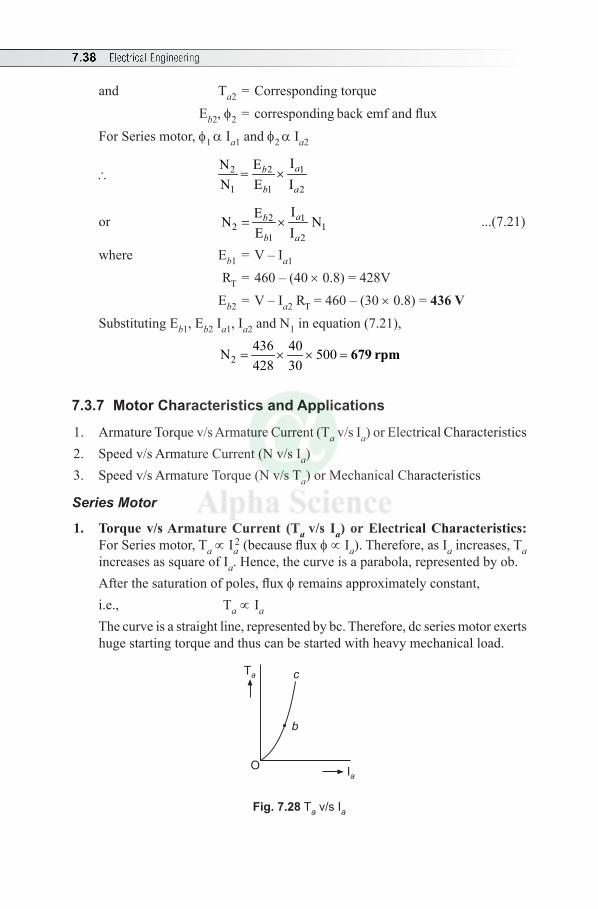
7.38 Electrical Engineering
and Ta2 = Corresponding torque Eb2, f2 = corresponding back emf and flux For Series motor, f1 a Ia1 and f2 a Ia2
\ 22 1
1 1 2
IENN E I
ab
b a= ×
or 2 12 1
1 2
IEN NE I
ab
b a= × ...(7.21)
where Eb1 = V – Ia1
RT = 460 – (40 × 0.8) = 428V Eb2 = V – Ia2 RT = 460 – (30 × 0.8) = 436 VSubstituting Eb1, Eb2 Ia1, Ia2 and N1 in equation (7.21),
2
436 40N 500428 30
= × × = 679 rpm
7.3.7 Motor Characteristics and Applications
1. Armature Torque v/s Armature Current (Ta v/s Ia) or Electrical Characteristics2. Speed v/s Armature Current (N v/s Ia) 3. Speed v/s Armature Torque (N v/s Ta) or Mechanical Characteristics
Series Motor
1. Torque v/s Armature Current (Ta v/s Ia) or Electrical Characteristics: For Series motor, Ta ∝ Ia
2 (because flux f ∝ Ia). Therefore, as Ia increases, Ta increases as square of Ia. Hence, the curve is a parabola, represented by ob.
After the saturation of poles, flux f remains approximately constant, i.e., Ta ∝ Ia
The curve is a straight line, represented by bc. Therefore, dc series motor exerts huge starting torque and thus can be started with heavy mechanical load.
Ta
OIa
b
c
Fig. 7.28 Ta v/s Ia
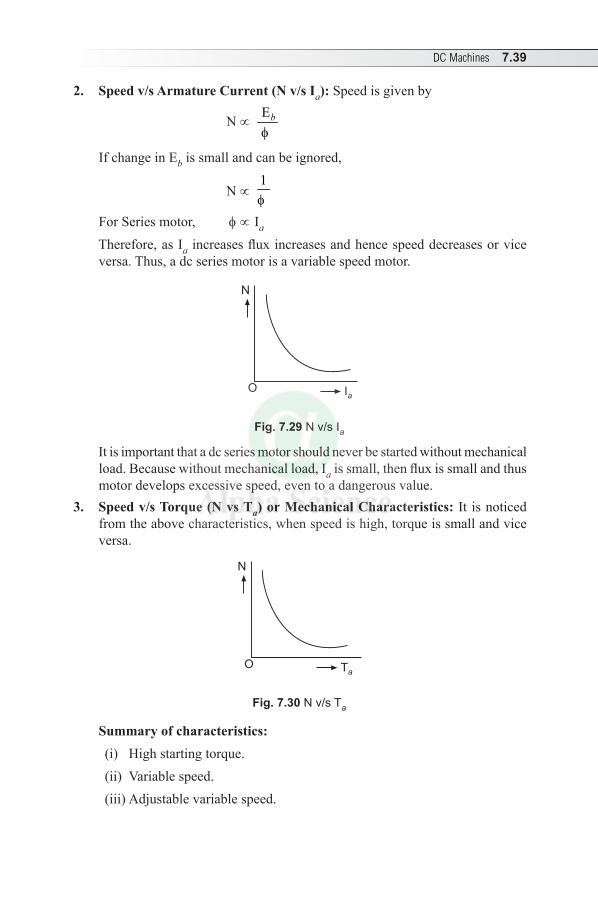
DC Machines 7.39
2. Speed v/s Armature Current (N v/s Ia): Speed is given by
N ∝ E b
f
If change in Eb is small and can be ignored,
N ∝ 1 f
For Series motor, f ∝ Ia
Therefore, as Ia increases flux increases and hence speed decreases or vice versa. Thus, a dc series motor is a variable speed motor.
N
O Ia
Fig. 7.29 N v/s Ia
It is important that a dc series motor should never be started without mechanical load. Because without mechanical load, Ia is small, then flux is small and thus motor develops excessive speed, even to a dangerous value.
3. Speed v/s Torque (N vs Ta) or Mechanical Characteristics: It is noticed from the above characteristics, when speed is high, torque is small and vice versa.
N
O Ta
Fig. 7.30 N v/s Ta
Summary of characteristics:(i) High starting torque.(ii) Variable speed.(iii) Adjustable variable speed.
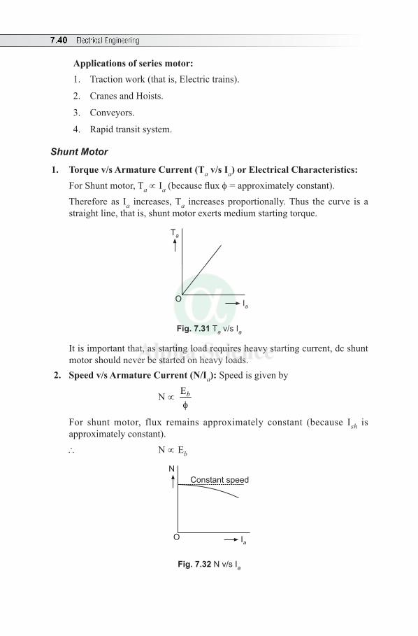
7.40 Electrical Engineering
Applications of series motor:1. Traction work (that is, Electric trains).
2. Cranes and Hoists.
3. Conveyors.
4. Rapid transit system.
Shunt Motor
1. Torque v/s Armature Current (Ta v/s Ia) or Electrical Characteristics: For Shunt motor, Ta ∝ Ia (because flux f = approximately constant). Therefore as Ia increases, Ta increases proportionally. Thus the curve is a
straight line, that is, shunt motor exerts medium starting torque.
Ta
OIa
Fig. 7.31 Ta v/s Ia
It is important that, as starting load requires heavy starting current, dc shunt motor should never be started on heavy loads.
2. Speed v/s Armature Current (N/Ia): Speed is given by
N ∝ Eb
f
For shunt motor, flux remains approximately constant (because Ish is approximately constant).
\ N ∝ Eb
N
O Ia
Constant speed
Fig. 7.32 N v/s Ia
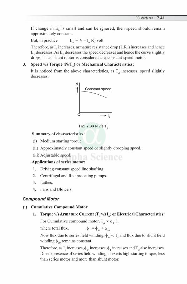
DC Machines 7.41
If change in Eb is small and can be ignored, then speed should remain approximately constant.
But, in practice Eb = V – Ia Ra volt Therefore, as Ia increases, armature resistance drop (Ia Ra) increases and hence
Eb decreases. As Eb decreases the speed decreases and hence the curve slightly drops. Thus, shunt motor is considered as a constant-speed motor.
3. Speed v/s Torque (N/Ta) or Mechanical Characteristics: It is noticed from the above characteristics, as Ta increases, speed slightly
decreases.
N
O Ia
Constant speed
Fig. 7.33 N v/s Ta
Summary of characteristics: (i) Medium starting torque.(ii) Approximately constant speed or slightly drooping speed.(iii) Adjustable speed.
Applications of series motor:1. Driving constant speed line shafting.2. Centrifugal and Reciprocating pumps.3. Lathes. 4. Fans and Blowers.
Compound Motor
(i) Cumulative Compound Motor1. Torque v/s Armature Current (Ta v/s Ia) or Electrical Characteristics: For Cumulative compound motor, Ta ∝ fT Ia
where total flux, fT = fse + fsh
Now flux due to series field winding, fse ∝ Ia and flux due to shunt field winding fsh remains constant.
Therefore, as Ia increases, fse increases, fT increases and Ta also increases. Due to presence of series field winding, it exerts high starting torque, less than series motor and more than shunt motor.
Ia
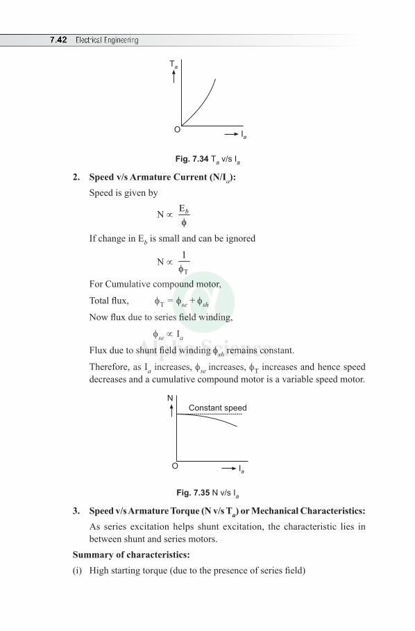
7.42 Electrical Engineering
Ta
OIa
Fig. 7.34 Ta v/s Ia
2. Speed v/s Armature Current (N/Ia): Speed is given by
N ∝ Eb
f
If change in Eb is small and can be ignored
N ∝ T
1f
For Cumulative compound motor,
Total flux, fT = fse + fsh
Now flux due to series field winding,
fse ∝ Ia
Flux due to shunt field winding fsh remains constant.
Therefore, as Ia increases, fse increases, fT increases and hence speed decreases and a cumulative compound motor is a variable speed motor.
N
O Ia
Constant speed
Fig. 7.35 N v/s Ia
3. Speed v/s Armature Torque (N v/s Ta) or Mechanical Characteristics: As series excitation helps shunt excitation, the characteristic lies in
between shunt and series motors. Summary of characteristics:(i) High starting torque (due to the presence of series field)
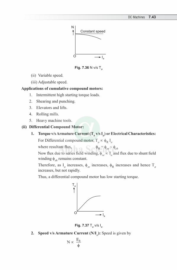
DC Machines 7.43
N
O Ia
Constant speed
Fig. 7.36 N v/s Ta
(ii) Variable speed.(iii) Adjustable speed.
Applications of cumulative compound motors:1. Intermittent high starting torque loads.2. Shearing and punching.3. Elevators and lifts.4. Rolling mills.5. Heavy machine tools.
(ii) Differential Compound Motor:1. Torque v/s Armature Current (Ta v/s Ia) or Electrical Characteristics: For Differential compound motor, Ta ∝ fR Ia
where resultant flux, fR = fse ~ fsh
Now flux due to series field winding, fse ∝ Ia and flux due to shunt field winding fsh remains constant.
Therefore, as Ia increases, fse increases, fR increases and hence Ta increases, but not rapidly.
Thus, a differential compound motor has low starting torque.
Ta
OIa
Fig. 7.37 Ta v/s Ia
2. Speed v/s Armature Current (N/Ia): Speed is given by
N ∝ Eb
f
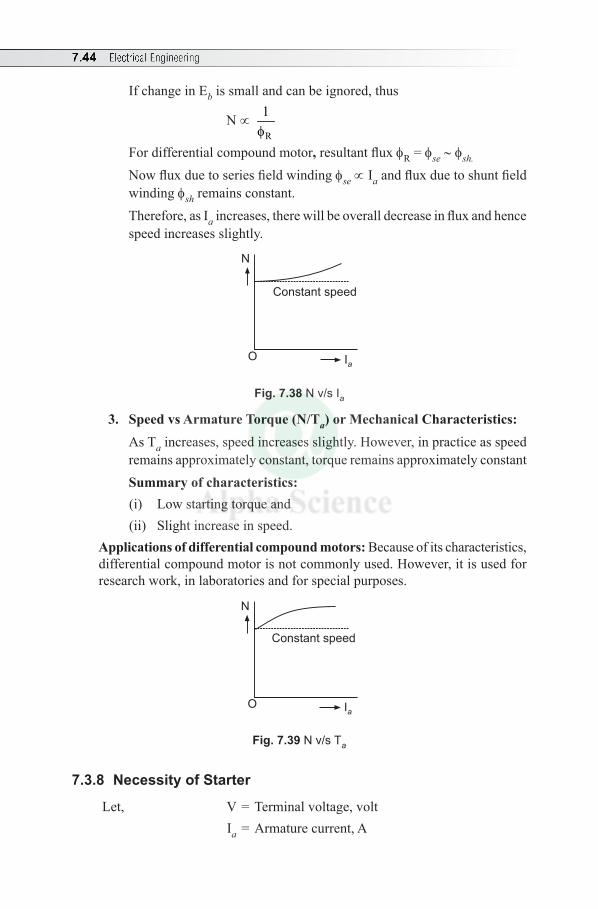
7.44 Electrical Engineering
If change in Eb is small and can be ignored, thus
N ∝ R
1f
For differential compound motor, resultant flux fR = fse ~ fsh.
Now flux due to series field winding fse ∝ Ia and flux due to shunt field winding fsh remains constant.
Therefore, as Ia increases, there will be overall decrease in flux and hence speed increases slightly.
N
O Ia
Constant speed
Fig. 7.38 N v/s Ia
3. Speed vs Armature Torque (N/Ta) or Mechanical Characteristics: As Ta increases, speed increases slightly. However, in practice as speed
remains approximately constant, torque remains approximately constant Summary of characteristics:
(i) Low starting torque and(ii) Slight increase in speed.
Applications of differential compound motors: Because of its characteristics, differential compound motor is not commonly used. However, it is used for research work, in laboratories and for special purposes.
N
O Ia
Constant speed
Fig. 7.39 N v/s Ta
7.3.8 Necessity of Starter
Let, V = Terminal voltage, volt Ia = Armature current, A
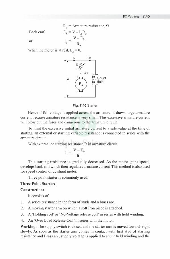
DC Machines 7.45
Ra = Armature resistance, W Back emf, Eb = V – Ia Ra
or Ia = V – E
Rb
a
When the motor is at rest, Eb = 0.
V Shuntfield
+
–
Iam
Ish
Ra
+
–
+
–
IL
R
Fig. 7.40 Starter
Hence if full voltage is applied across the armature, it draws large armature current because armature resistance is very small. This excessive armature current will blow out the fuses and dangerous to the armature circuit.
To limit the excessive initial armature current to a safe value at the time of starting, an external or starting variable resistance is connected in series with the armature circuit.
With external or starting resistance R in armature circuit,
Ia = V – ER
b
a
This starting resistance is gradually decreased. As the motor gains speed, develops back emf which then regulates armature current. This method is also used for speed control of dc shunt motor.
Three point starter is commonly used.Three-Point Starter:Construction:
It consists of1. A series resistance in the form of studs and a brass arc.2. A moving starter arm on which a soft Iron piece is attached.3. A‘Holdingcoil’or‘No-Voltagereleasecoil’inserieswithfieldwinding.4. An ‘Over Load Release Coil’ in series with the motor.Working: The supply switch is closed and the starter arm is moved towards right slowly.As soon as the starter arm comes in contactwithfirst stud of startingresistanceandBrassarc,supplyvoltageisappliedtoshuntfieldwindingandthe
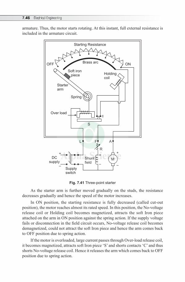
7.46 Electrical Engineering
armature. Thus, the motor starts rotating. At this instant, full external resistance is included in the armature circuit.
+
–
L F A
R
M
+
–
c
Shuntfield
Supplyswitch
DCsupply
S
Over load
Spring
Starterarm
Soft ironpiece Holding
coil
Brass arcONOFF
Starting Resistance
+
–
Fig. 7.41 Three-point starter
As the starter arm is further moved gradually on the studs, the resistance decreases gradually and hence the speed of the motor increases.
In ON position, the starting resistance is fully decreased (called cut-out position), the motor reaches almost its rated speed. In this position, the No-voltage release coil or Holding coil becomes magnetized, attracts the soft Iron piece attached on the arm in ON position against the spring action. If the supply voltage fails or disconnection in the field circuit occurs, No-voltage release coil becomes demagnetized, could not attract the soft Iron piece and hence the arm comes back to OFF position due to spring action.
If the motor is overloaded, large current passes through Over-load release coil, it becomes magnetized, attracts soft Iron piece ‘S’ and shorts contacts ‘C’ and thus shorts No-voltage release coil. Hence it releases the arm which comes back to OFF position due to spring action.

DC Machines 7.47
Multiple Choice Questions
Choose the Correct Answer
1. By applying Fleming’s right hand rule to an electric generator, you can find(a) direction of magnetic field (b) direction of induced emf (c) direction of rotor motion (d) law of induction
2. The yoke of a dc generator is made of ......(a) silicon steel (b) soft iron (c) wrought iron (d) cast steel
3. The armature of a dc generator is made of (a) soft iron (b) wrought iron (c) silicon steel (d) cast steel
4. The armature of a dc generator is laminated to reduce(a) eddy current loss (b) hysteresis loss(c) copper loss (d) friction loss
5. Commutator in dc machine is made up of ......(a) iron segments(b) copper segments (c) both iron laminations and copper segments(d) none of these
6. The function of a commutator in dc generator is(a) to collect current from conductors (b) to change dc to ac (c) to conduct the current to brushes(d) to change ac to dc
7. The brushes in a dc generator are made of carbon because(a) they are cheap(b) their resistance is high (c) they lubricate and polish the commutator(d) they are the good conductors
8. Carbon brushes are used in dc machines because(a) they have longer life (b) they reduce armature reaction (c) they have small resistance (d) they reduce sparking
9. High voltage generators use ...... winding(a) lap (b) wave(c) either lap or wave (d) none of these
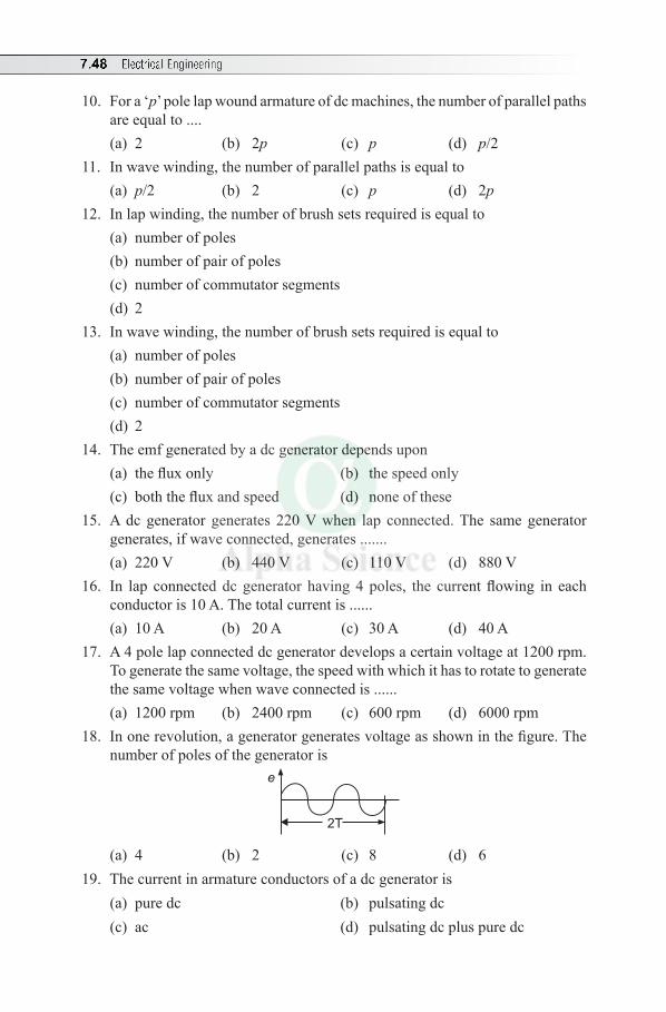
7.48 Electrical Engineering
10. For a ‘p’ pole lap wound armature of dc machines, the number of parallel paths are equal to ....(a) 2 (b) 2p (c) p (d) p/2
11. In wave winding, the number of parallel paths is equal to(a) p/2 (b) 2 (c) p (d) 2p
12. In lap winding, the number of brush sets required is equal to(a) number of poles(b) number of pair of poles (c) number of commutator segments(d) 2
13. In wave winding, the number of brush sets required is equal to(a) number of poles(b) number of pair of poles (c) number of commutator segments (d) 2
14. The emf generated by a dc generator depends upon (a) the flux only (b) the speed only (c) both the flux and speed (d) none of these
15. A dc generator generates 220 V when lap connected. The same generator generates, if wave connected, generates .......(a) 220 V (b) 440 V (c) 110 V (d) 880 V
16. In lap connected dc generator having 4 poles, the current flowing in each conductor is 10 A. The total current is ...... (a) 10 A (b) 20 A (c) 30 A (d) 40 A
17. A 4 pole lap connected dc generator develops a certain voltage at 1200 rpm. To generate the same voltage, the speed with which it has to rotate to generate the same voltage when wave connected is ......(a) 1200 rpm (b) 2400 rpm (c) 600 rpm (d) 6000 rpm
18. In one revolution, a generator generates voltage as shown in the figure. The number of poles of the generator is
2T
e
(a) 4 (b) 2 (c) 8 (d) 6 19. The current in armature conductors of a dc generator is
(a) pure dc (b) pulsating dc(c) ac (d) pulsating dc plus pure dc
DC Machines 7.49
20. The series field of a short shunt dc generator is excited by ...... current(a) shunt (b) armature (c) load (d) external
21. In dc shunt generator, the armature and field windings are connected (a) in parallel (b) in series(c) in series-parallel (d) none of these
22. Residual magnetism is necessary in a dc .......(a) shunt generator (b) separately excited generator (c) shunt motor (d) series motor
23. Fleming’s left hand rule is applicable to(a) dc generator (b) transformer(c) dc motor (d) both (a) and (b)
24. The back emf in a dc motor is maximum at (a) no-load (b) half full-load(c) full-load (d) square of full-load
25. Mechanical power developed by the dc motor is maximum when back emf is equal to (a) to supply voltage (b) two times of supply voltage(c) half of the supply voltage (d) zero
26. The back emf in a dc motor ........(a) aids the applied voltage (b) opposes the applied voltage (c) aids the armature current (d) opposes the field current
27. In dc motor, the electrical equivalent of the mechanical power developed is....(a) V IL (b) Eb Ia (c) Ia
2Ra (d) VIa
28. The relationship between the applied voltage and back emf is(a) V = Eb + Ia Ra (b) V = Eb – Ia Ra (c) V = Eb (d) none of these
29. The speed of a dc motor is ........(a) directly proportional to the flux(b) inversely proportional to the flux (c) inversely proportional to applied voltage(d) none of these
30. The torque developed by a dc motor is directly proportional to ........(a) V Ia (b) fIa (c) IaRa (d) EbIa
31. The torque developed by a dc series motor is 20 N-m when drawing 20 A. If the current is doubled, the torque developed becomes (a) 20 N-m (b) 40 N-m (c) 80 N-m (d) 160 N-m
7.50 Electrical Engineering
32. The torque of a shunt motor is proportional to(a) armature current (b) applied voltage(c) square of armature current (d) none of these
33. The shaft torque of a dc motor is less than its armature torque due to the following losses(a) copper and iron (b) copper and mechanical(c) iron and friction (d) copper, iron and mechanical
34. When the supply terminals of a dc shunt motor are reversed, then the motor(a) will stop(b) will run at its normal speed in the same direction as before(c) direction of rotation will reverse(d) will run at high speed in same direction
35. When the field winding of a dc motor is opened, when it is running at a particular speed, its speed becomes ......(a) zero (b) infinity (c) rated speed (d) none of these
36. When load is removed, ...... motor will run at the highest speed(a) shunt (b) cumulative compound(c) differential compound (d) series
37. The speed of a dc ...... motor is almost constant(a) series (b) shunt(c) compound motors (d) none of these
38. DC ........ motor should never be started on no-load (a) series (b) shunt(c) cumulative compound (d) differential compound
39. A dc motor is still used in industrial applications because it is(a) cheap (b) simple in construction (c) provides fine speed control (d) none of these
40. A dc motor draws a large current at starting due to (a) high value of Ra (b) low back emf(c) low flux in shunt field (d) none of these
41. Which dc motor is preferred for constant speed line shafting(a) cumulative compound motor (b) differential compound motor(c) shunt motor (d) series motor
42. For the movement of trains, dc ........ motors are used(a) shunt (b) series(c) compound motors (d) none of these
DC Machines 7.51
43. The speed of a series motor at no-load is(a) zero (b) 1500 rpm (c) 3000 rpm (d) infinity
44. At the instant of starting a dc motor, its back emf is (a) zero (b) maximum (c) minimum (d) infinity
45. A dc motor draws a large current at the time of starting because ......(a) Ra is high (b) Eb = 0 (c) Rf is small (d) none of these
46. The function of a starter in a dc motor is to ......(a) control its speed(b) increase its torque(c) limit the starting current to a safe value(d) none of these
47. The current drawn by armature of a dc motor is(a) V/Ra (b) Eb/Ra
(c) (V – Eb) /Ra (d) (Eb – V) /Ra 48. For ‘P’ pole lap wound armature dc machine, no. of parallel ports ......
(a) 2 (b) 2P (c) P (d) P/2
Answers:—
1. (b) 2. (d) 3. (c) 4. (a) 5. (b) 6. (d) 7. (c) 8. (d) 9. (b) 10. (c)
11. (b) 12. (a) 13. (d) 14. (c) 15. (b) 16. (d) 17. (c) 18. (a) 19. (c) 20. (c)
21. (a) 22. (a) 23. (c) 24. (a) 25. (c) 26. (b) 27. (b) 28. (a) 29. (b) 30. (b)
31. (c) 32. (a) 33. (c) 34. (b) 35. (b) 36. (d) 37. (b) 38. (a) 39. (c) 40. (b)
41. (c) 42. (b) 43. (d) 44. (a) 45. (b) 46. (c) 47. (c) 48. (c)
Review Questions
1. Explain the working principle of a dc machine as a generator and motor with suitable diagrams.
2. Explain with a neat sketch the constructional features of a dc machine and mention the function of each part.
3. What are the functions of yoke, armature, poles and brushes in a dc generator?4. Derive the emf equation of dc generator.5. Sketch and explain the external characteristics of dc shunt generator and
mention its applications.
7.52 Electrical Engineering
6. What is back emf ? Explain its significance under no-load and full-load condition in a dc motor.
7. Derive an expression for armature torque developed in a dc motor.8. Derive an expression for the torque developed in a dc motor and show that the
torque is proportional to the product of flux and armature current.9. Sketch and explain the characteristics of a dc shunt motor.10. Discuss the characteristics, of Ta/Ia and N/Ia for a series motor. 11. Justify the following statements: (i) a resistance must be kept in series with
armature at the time of starting a dc motor and (ii) a series motor should never be started without a mechanical load.
12. From the characteristics of dc series motor, justify (a) a series motor should not be started on no-load and (b) a series motor has high starting torque.
13. What is the necessity of a starter for dc motor? With a neat diagram explain the working of a three point starter.
Exercises
1. 1. A 20 kW compound generator works on full load with a terminal voltage of 250 V. Ra = 0.05 W, Rse = 0.025 W and Rsh = 100 W. Find emf if generator is short shunt. (Ans: 256.13 V)
2. A shunt machine connected to 250 V mains has an armature resistance (including brushes) of 0.12 W and the resistance of field circuit is 100 W. Find the ratio of speed as a generator to the speed of a motor. The line current in each case is 80 A. (Ans: 1.07)
3. A 4 pole, lap wound, 220 V dc shunt motor has an armature resistance of 0.4 W and shunt field resistance of 220 W. It is running at 1500 rpm, when it is taking 40 A from supply. Find the speed of the motor when the motor is taking 10 A from supply. (Ans: 1588 rpm)
4. A 4 pole, 250 V series motor has a wave wound armature with 1254 conductors. The flux per pole is 22 mWb, when motor is taking 50 A. Armature resistance is 0.2 W and series field resistance is 0.2 W. Calculate speed of motor. (Ans: 250 rpm)
5. A 230 V dc shunt motor takes a no-load current of 2 A and runs at 1100 rpm. If full load current is 40 A, find speed at full load. Assume flux remains constant, and Ra = 0.25 W. (Ans: 977 rpm)
6. The armature of a shunt motor has a lap winding accommodated in 60 slots, each containing 20 conductors. If the useful flux/pole is 28 mWb, calculate the total torque developed in N-m when the armature current is 50 A.
(Ans: Ta = 267.38 N-m)
DC Machines 7.53
7. A 4 pole, dc shunt motor takes 30 A from 220 V supply. The armature and shunt field resistances are 0.5 W and 110 W respectively. The armature is lap wound having a total of 300 conductors. Flux/pole is 20 mWb, calculate the speed and the torque developed. (Ans: N = 2060 rpm, Ta = 26.73 N-m)
8. A 4 pole, 250 V, wave wound shunt motor gives 10 kW when running at 1000 rpm and drawing armature of 60 A. It has 560 conductors. Its armature resistance is 0.2 W. Assuming a drop of 1 V per brush, determine (a) total torque, (b) useful torque and (c) useful flux per pole.
(Ans: 135.22 N-m, 95.49 N-m, 0.0126 Wb)9. A 4 pole dc shunt motor takes 22.5 A from 250 V supply. Ra = 0.5 W and
Rf = 125 W. Armature is wave wound with 300 conductors. If flux per pole is 0.02 Wb, calculate (i) Speed, (ii) Torque developed and (iii) Power developed. (Ans: 1199 rpm, 39.15 N-m, 4914.87 W)
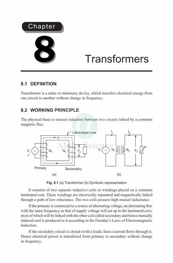
8.1 DEFINITION
Transformer is a static or stationary device, which transfers electrical energy from one circuit to another without change in frequency.
8.2 WORKING PRINCIPLE
The physical basis is mutual induction between two circuits linked by a common magnetic flux.
N2 V2
I2I1
V1 ~ N1V1 V2~
Laminated core
SecondaryPrimary
N1 N2
f
(a) (b)
Fig. 8.1 (a) Transformer (b) Symbolic representation
It consists of two separate inductive coils or windings placed on a common laminated core. These windings are electrically separated and magnetically linked through a path of low reluctance. The two coils possess high mutual inductance.
If the primary is connected to a source of alternating voltage, an alternating flux with the same frequency as that of supply voltage will set up in the laminated core, most of which will be linked with the other coil called secondary and hence mutually induced emf is produced in it according to the Faraday’s Laws of Electromagnetic Induction.
If the secondary circuit is closed (with a load), then a current flows through it. Hence electrical power is transferred from primary to secondary without change in frequency.
Transformers8Chapter
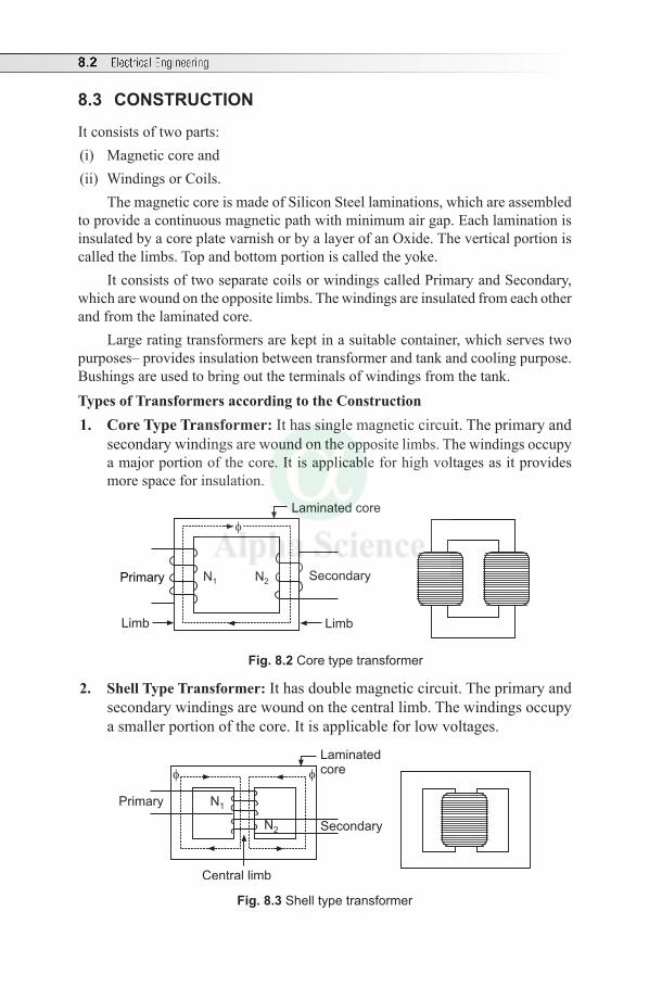
8.2 Electrical Engineering
8.3 CONSTRUCTION
It consists of two parts:(i) Magnetic core and(ii) Windings or Coils.
The magnetic core is made of Silicon Steel laminations, which are assembled to provide a continuous magnetic path with minimum air gap. Each lamination is insulated by a core plate varnish or by a layer of an Oxide. The vertical portion is called the limbs. Top and bottom portion is called the yoke.
It consists of two separate coils or windings called Primary and Secondary, which are wound on the opposite limbs. The windings are insulated from each other and from the laminated core.
Large rating transformers are kept in a suitable container, which serves two purposes– provides insulation between transformer and tank and cooling purpose. Bushings are used to bring out the terminals of windings from the tank.Types of Transformers according to the Construction1. Core Type Transformer: It has single magnetic circuit. The primary and
secondary windings are wound on the opposite limbs. The windings occupy a major portion of the core. It is applicable for high voltages as it provides more space for insulation.
Laminated core
Limb
N1 N2SecondaryPrimary
Limb
Fig. 8.2 Core type transformer
2. Shell Type Transformer: It has double magnetic circuit. The primary and secondary windings are wound on the central limb. The windings occupy a smaller portion of the core. It is applicable for low voltages.
Laminatedcore
Secondary
Primary N1
N2
Central limb
Fig. 8.3 Shell type transformer
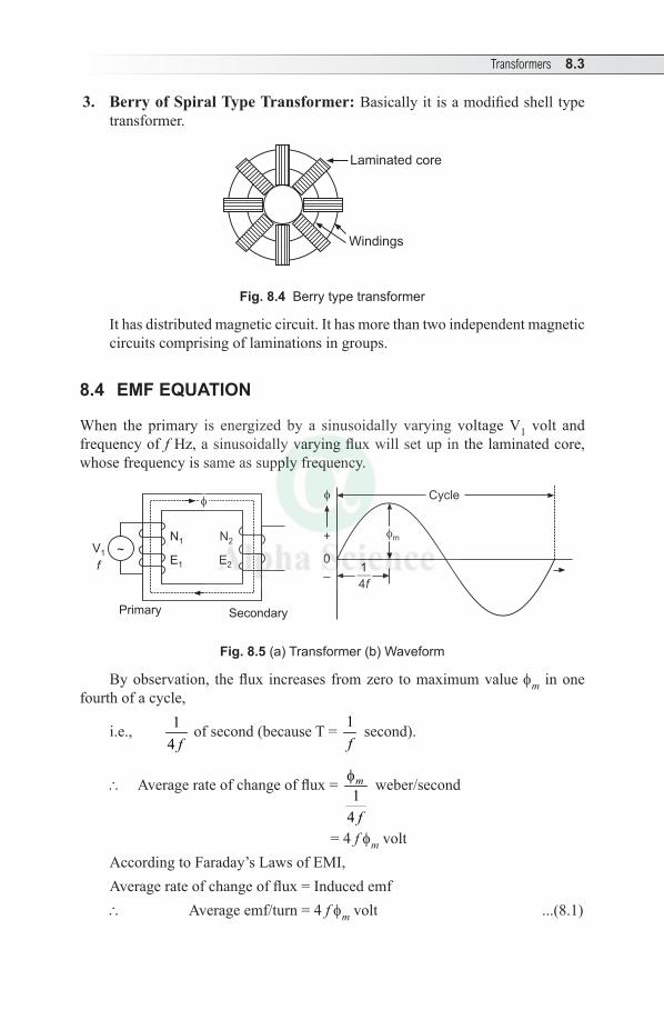
Transformers 8.3
3. Berry of Spiral Type Transformer: Basically it is a modified shell type transformer.
Laminated core
Windings
Fig. 8.4 Berry type transformer
It has distributed magnetic circuit. It has more than two independent magnetic circuits comprising of laminations in groups.
8.4 EMF EQUATION
When the primary is energized by a sinusoidally varying voltage V1 volt and frequency of f Hz, a sinusoidally varying flux will set up in the laminated core, whose frequency is same as supply frequency.
V1 ~
SecondaryPrimary
N1
E1
N2
f E2
Cycle
m
1
4
f
+
0
–
Fig. 8.5 (a) Transformer (b) Waveform
By observation, the flux increases from zero to maximum value fm in one fourth of a cycle,
i.e., 14 f
of second (because T = 1f
second).
\ Average rate of change of flux = 1
4
m
f
f weber/second
= 4 f fm voltAccording to Faraday’s Laws of EMI, Average rate of change of flux = Induced emf\ Average emf/turn = 4 f fm volt ...(8.1)
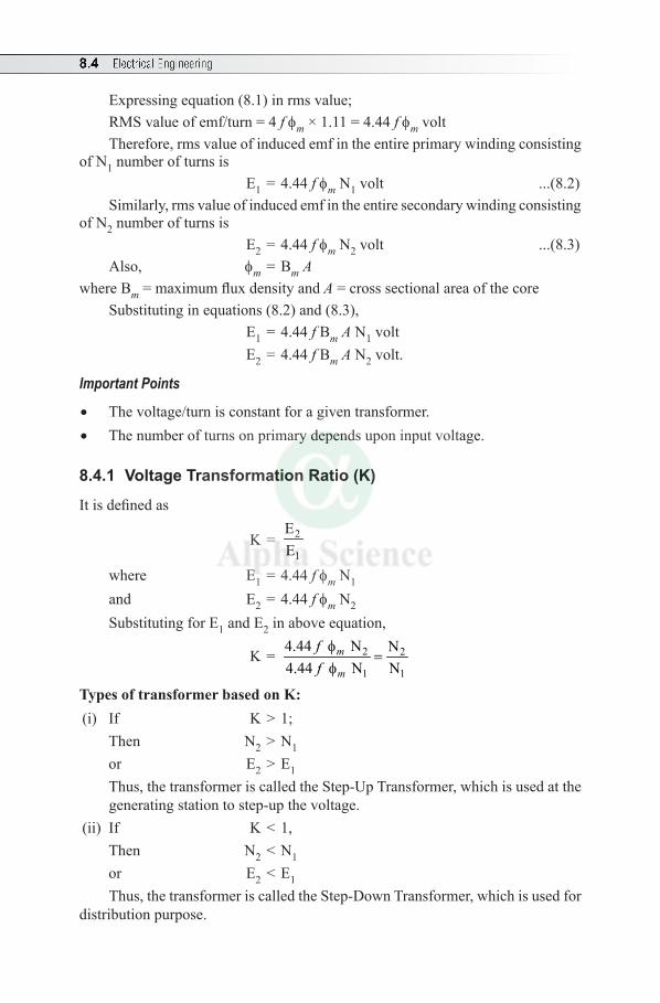
8.4 Electrical Engineering
Expressing equation (8.1) in rms value;RMS value of emf/turn = 4 f fm × 1.11 = 4.44 f fm volt Therefore, rms value of induced emf in the entire primary winding consisting
of N1 number of turns is E1 = 4.44 f fm N1 volt ...(8.2) Similarly, rms value of induced emf in the entire secondary winding consisting
of N2 number of turns is E2 = 4.44 f fm N2 volt ...(8.3)Also, fm = Bm A
where Bm = maximum flux density and A = cross sectional area of the coreSubstituting in equations (8.2) and (8.3), E1 = 4.44 f Bm A N1 volt E2 = 4.44 f Bm A N2 volt.
Important Points
• The voltage/turn is constant for a given transformer.• The number of turns on primary depends upon input voltage.
8.4.1 Voltage Transformation Ratio (K)
It is defined as
K = 2
1
EE
where E1 = 4.44 f fm N1
and E2 = 4.44 f fm N2
Substituting for E1 and E2 in above equation,
K = 2 2
1 1
4.44 N N4.44 N N
m
m
fff
=f
Types of transformer based on K: (i) If K > 1; Then N2 > N1 or E2 > E1 Thus, the transformer is called the Step-Up Transformer, which is used at the
generating station to step-up the voltage. (ii) If K < 1, Then N2 < N1 or E2 < E1
Thus, the transformer is called the Step-Down Transformer, which is used for distribution purpose.
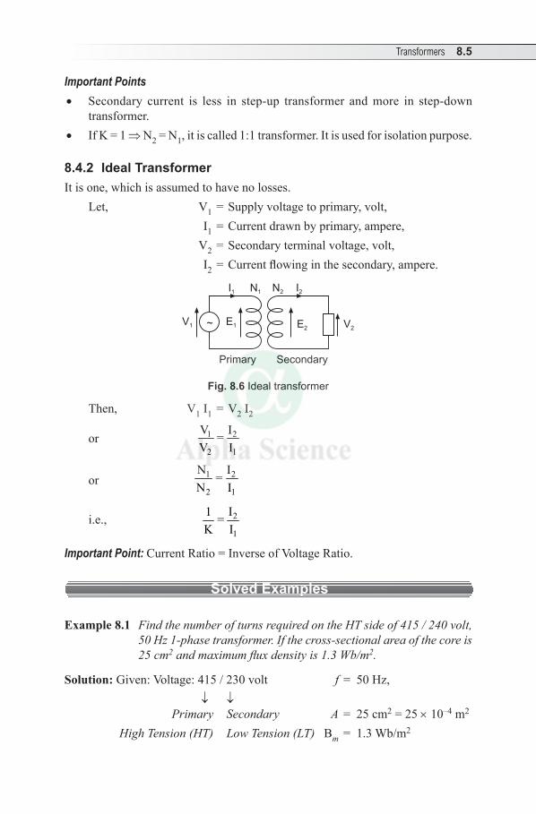
Transformers 8.5
Important Points • Secondary current is less in step-up transformer and more in step-down
transformer. • If K = 1 ⇒ N2 = N1, it is called 1:1 transformer. It is used for isolation purpose.
8.4.2 Ideal TransformerIt is one, which is assumed to have no losses.
Let, V1 = Supply voltage to primary, volt, I1 = Current drawn by primary, ampere, V2 = Secondary terminal voltage, volt, I2 = Current flowing in the secondary, ampere.
V2E2E1V1 ~
I1 N1 I2N2
Primary Secondary
Fig. 8.6 Ideal transformer
Then, V1 I1 = V 2 I2
or 1 2
2 1
V I=V I
or 1 2
2 1
N I=N I
i.e., 2
1
I1 =K I
Important Point: Current Ratio = Inverse of Voltage Ratio.
Solved Examples
Example 8.1 Find the number of turns required on the HT side of 415 / 240 volt, 50 Hz 1-phase transformer. If the cross-sectional area of the core is 25 cm2 and maximum flux density is 1.3 Wb/m2.
Solution: Given: Voltage: 415 / 230 volt f = 50 Hz, ↓ ↓ Primary Secondary A = 25 cm2 = 25 × 10–4 m2
High Tension (HT) Low Tension (LT) Bm = 1.3 Wb/m2
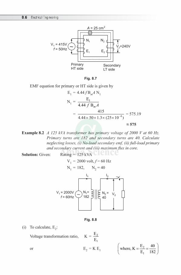
8.6 Electrical Engineering
SecondaryLT side
PrimaryHT side
N1
E1
N2
E2
V1 = 415V
= 50Hzf
A = 25 cm2
V2=240V
Fig. 8.7
EMF equation for primary or HT side is given by E1 = 4.44 f BmA N1
N1 = 1E4.44 Bmf A
= –4415
4.44 50 1.3 (25 10 )× × × × = 575.19
≈575
Example 8.2 A 125 kVA transformer has primary voltage of 2000 V at 60 Hz. Primary turns are 182 and secondary turns are 40. Calculate neglecting losses, (i) No-load secondary emf, (ii) full-load primary and secondary current and (iii) maximum flux in core.
Solution: Given: Rating = 125 kVA V1 = 2000 volt, f = 60 Hz N1 = 182, N2 = 40
N2 =
40V2
I2I1
V1 = 2000V
= 60Hzf ~N1=
182
Fig. 8.8
(i) To calculate, E2:
Voltage transformation ratio, K = 2
1
EE
or E2 = K E1 2
1
E 40where, KE 182
= =
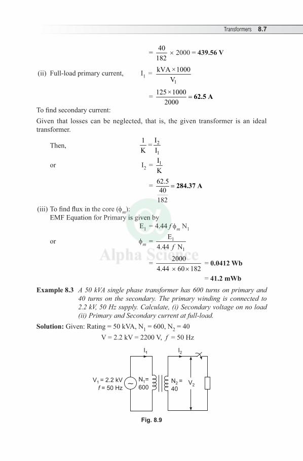
Transformers 8.7
= 40182
× 2000 =439.56V
(ii) Full-load primary current, I1 = 1
kVA ×1000V
= 125 ×10002000
= 62.5 A
To find secondary current: Given that losses can be neglected, that is, the given transformer is an ideal transformer.
Then, 2
1
I1 =K I
or I2 = 1IK
= 62.540
182
= 284.37 A
(iii) To find flux in the core (fm ): EMF Equation for Primary is given by
E1 = 4.44 f fm N1
or fm = 1
1
E4.44 Nf
= 20004.44 60 182× ×
= 0.0412 Wb
= 41.2 mWbExample 8.3 A 50 kVA single phase transformer has 600 turns on primary and
40 turns on the secondary. The primary winding is connected to 2.2 kV, 50 Hz supply. Calculate, (i) Secondary voltage on no load (ii) Primary and Secondary current at full-load.
Solution: Given: Rating = 50 kVA, N1 = 600, N2 = 40 V = 2.2 kV = 2200 V, f = 50 Hz
N2 =
40V2
I2I1
V1 = 2.2 kV
= 50 Hzf ~N1=
600
Fig. 8.9
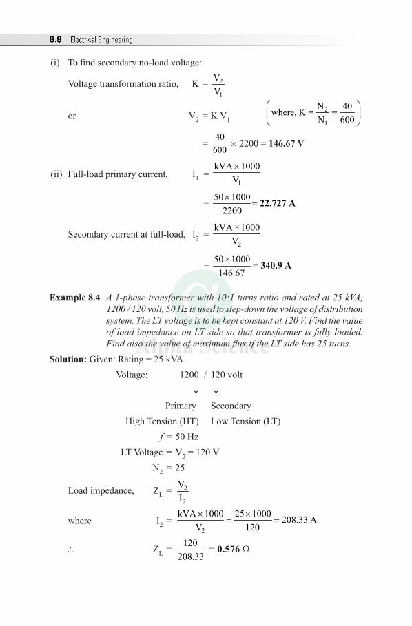
8.8 Electrical Engineering
(i) To find secondary no-load voltage:
Voltage transformation ratio, K = 2
1
VV
or V2 = K V1 2
1
N 40where, K = =N 600
= 40
600 × 2200 = 146.67V
(ii) Full-load primary current, I1 = 1
kVA 1000V×
= 50 1000
2200×
= 22.727 A
Secondary current at full-load, I2 = 2
kVA ×1000V
= 50 ×1000146.67
= 340.9 A
Example 8.4 A 1-phase transformer with 10:1 turns ratio and rated at 25 kVA, 1200 / 120 volt, 50 Hz is used to step-down the voltage of distribution system. The LT voltage is to be kept constant at 120 V. Find the value of load impedance on LT side so that transformer is fully loaded. Find also the value of maximum flux if the LT side has 25 turns.
Solution: Given: Rating = 25 kVA Voltage: 1200 / 120 volt ↓ ↓ Primary Secondary High Tension (HT) Low Tension (LT) f = 50 Hz LT Voltage = V2 = 120 V N2 = 25
Load impedance, ZL = 2
2
VI
where I2 = 2
kVA 1000 25 1000 208.33 AV 120× ×
= =
\ ZL = 120208.33
= 0.576W
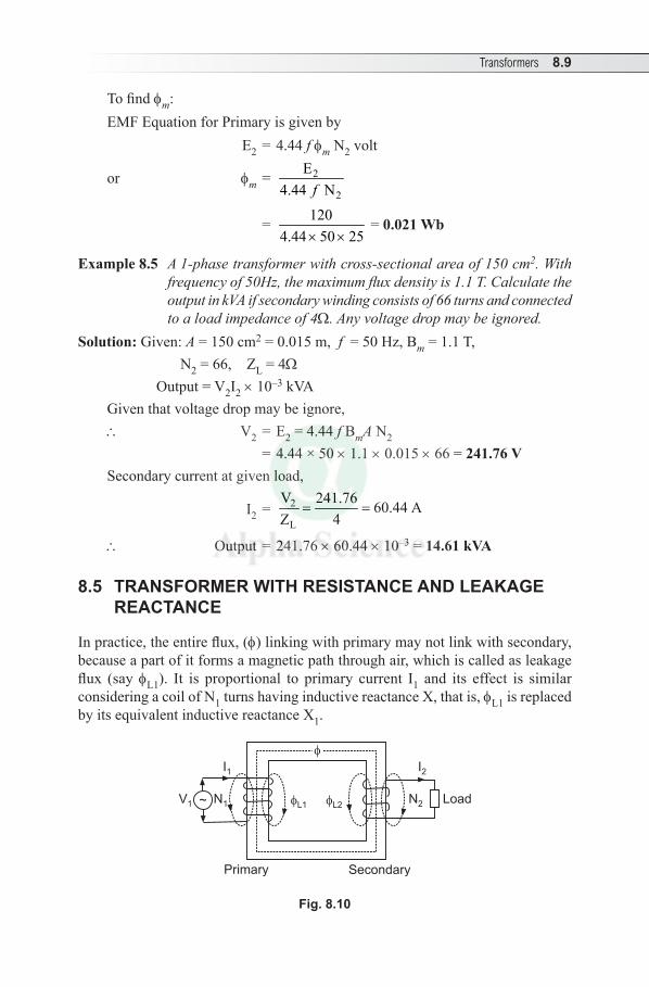
Transformers 8.9
To find fm:EMF Equation for Primary is given by E2 = 4.44 f fm N2 volt
or fm = 2
2
E4.44 Nf
= 120 0.021 Wb.4.44 50 25
=× ×
= 0.021 Wb
Example8.5 A 1-phase transformer with cross-sectional area of 150 cm2. With frequency of 50Hz, the maximum flux density is 1.1 T. Calculate the output in kVA if secondary winding consists of 66 turns and connected to a load impedance of 4W. Any voltage drop may be ignored.
Solution: Given: A = 150 cm2 = 0.015 m, f = 50 Hz, Bm = 1.1 T, N2 = 66, ZL = 4W
Output = V2I2 × 10–3 kVAGiven that voltage drop may be ignore,\ V2 = E2 = 4.44 f BmA N2 = 4.44 × 50 × 1.1 × 0.015 × 66 = 241.76VSecondary current at given load,
I2 = 2
L
V 241.76 60.44 AZ 4
= =
\ Output = 241.76 × 60.44 × 10–3 = 14.61kVA
8.5 TRANSFORMER WITH RESISTANCE AND LEAKAGE REACTANCE
In practice, the entire flux, (f) linking with primary may not link with secondary, because a part of it forms a magnetic path through air, which is called as leakage flux (say fL1). It is proportional to primary current I1 and its effect is similar considering a coil of N1 turns having inductive reactance X, that is, fL1 is replaced by its equivalent inductive reactance X1.
SecondaryPrimary
LoadL1 L2
N2
I2
N1
I1
V1
Fig. 8.10
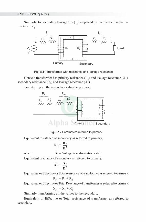
8.10 Electrical Engineering
Similarly, for secondary leakage flux fL2 is replaced by its equivalent inductive reactance X2.
V1
I1 R1X1
SecondaryPrimary
E1
fE2 Load
Z1
R2
Z2
X2 I1
~
Fig. 8.11 Transformer with resistance and leakage reactance
Hence a transformer has primary resistance (R1) and leakage reactance (X1), secondary resistance (R2) and leakage reactance (X2).
Transferring all the secondary values to primary;
SecondaryPrimary
X1X2
1
Re1
R1R2
1
Re1
Fig. 8.12 Parameters referred to primary
Equivalent resistance of secondary as referred to primary,
R21 = 2
2RK
where K = Voltage transformation ratioEquivalent reactance of secondary as referred to primary,
X21 = 2
2XK
Equivalent or Effective or Total resistance of transformer as referred to primary, Re1 = R1 + R2
1
Equivalent or Effective or Total Reactance of transformer as referred to primary, Xe1 = X1 + X2
1
Similarly transforming all the values to the secondary,Equivalent or Effective or Total resistance of transformer as referred to
secondary,
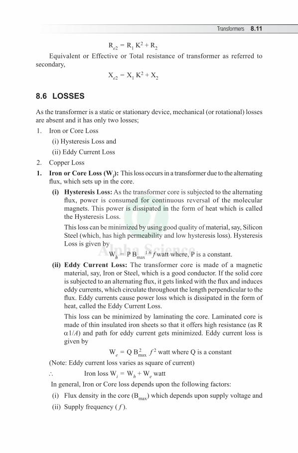
Transformers 8.11
Re2 = R1 K2 + R2
Equivalent or Effective or Total resistance of transformer as referred to secondary,
Xe2 = X1 K2 + X2
8.6 LOSSES
As the transformer is a static or stationary device, mechanical (or rotational) losses are absent and it has only two losses; 1. Iron or Core Loss
(i) Hysteresis Loss and(ii) Eddy Current Loss
2. Copper Loss1. Iron or Core Loss (Wi): This loss occurs in a transformer due to the alternating
flux, which sets up in the core.(i) Hysteresis Loss: As the transformer core is subjected to the alternating
flux, power is consumed for continuous reversal of the molecular magnets. This power is dissipated in the form of heat which is called the Hysteresis Loss.
This loss can be minimized by using good quality of material, say, Silicon Steel (which, has high permeability and low hysteresis loss). Hysteresis Loss is given by
Wh = P Bmax1.6 f watt where, P is a constant.
(ii) Eddy Current Loss: The transformer core is made of a magnetic material, say, Iron or Steel, which is a good conductor. If the solid core is subjected to an alternating flux, it gets linked with the flux and induces eddy currents, which circulate throughout the length perpendicular to the flux. Eddy currents cause power loss which is dissipated in the form of heat, called the Eddy Current Loss.
This loss can be minimized by laminating the core. Laminated core is made of thin insulated iron sheets so that it offers high resistance (as R a1/A) and path for eddy current gets minimized. Eddy current loss is given by
We = Q Bmax2 f 2 watt where Q is a constant
(Note: Eddy current loss varies as square of current)\ Iron loss Wi = Wh + We watt In general, Iron or Core loss depends upon the following factors:(i) Flux density in the core (Bmax) which depends upon supply voltage and(ii) Supply frequency ( f ).
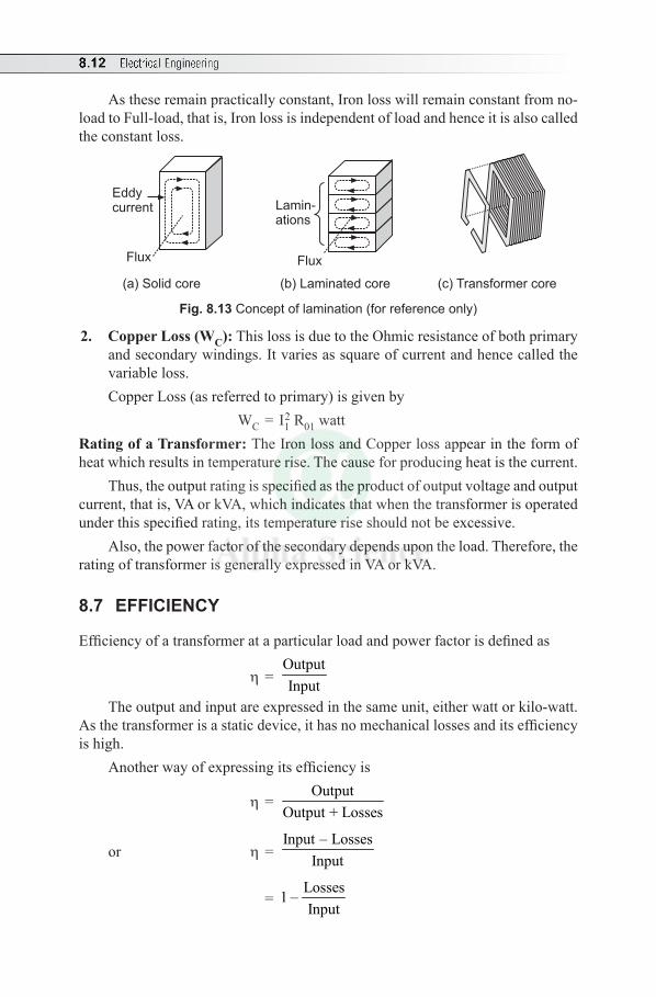
8.12 Electrical Engineering
As these remain practically constant, Iron loss will remain constant from no-load to Full-load, that is, Iron loss is independent of load and hence it is also called the constant loss.
Eddycurrent
Flux
Lamin-ations
Flux
(a) Solid core (b) Laminated core (c) Transformer core
Fig. 8.13 Concept of lamination (for reference only)
2. Copper Loss (WC): This loss is due to the Ohmic resistance of both primary and secondary windings. It varies as square of current and hence called the variable loss.Copper Loss (as referred to primary) is given by WC = I1
2 R01 wattRating of a Transformer: The Iron loss and Copper loss appear in the form of heat which results in temperature rise. The cause for producing heat is the current.
Thus, the output rating is specified as the product of output voltage and output current, that is, VA or kVA, which indicates that when the transformer is operated under this specified rating, its temperature rise should not be excessive.
Also, the power factor of the secondary depends upon the load. Therefore, the rating of transformer is generally expressed in VA or kVA.
8.7 EFFICIENCY
Efficiency of a transformer at a particular load and power factor is defined as
h = OutputInput
The output and input are expressed in the same unit, either watt or kilo-watt. As the transformer is a static device, it has no mechanical losses and its efficiency is high.
Another way of expressing its efficiency is
h = Output
Output + Losses
or h = Input – Losses
Input
= Losses1 –Input
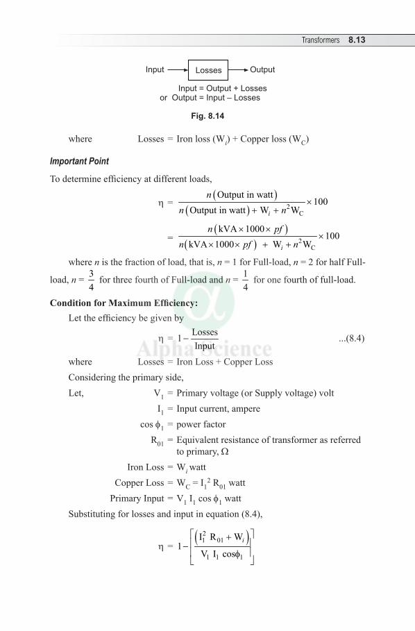
Transformers 8.13
LossesInput Output
Input = Output + Lossesor Output = Input – Losses
Fig. 8.14
where Losses = Iron loss (Wi) + Copper loss (WC)
Important Point
To determine efficiency at different loads,
h = ( )
( ) 2C
Output in watt100
Output in watt W Wi
nn n
×+ +
= ( )
( ) 2C
kVA 1000100
kVA 1000 W Wi
n pfn pf n
× ××
× × + +
where n is the fraction of load, that is, n = 1 for Full-load, n = 2 for half Full-
load, n = 34
for three fourth of Full-load and n = 14
for one fourth of full-load.
ConditionforMaximumEfficiency:Let the efficiency be given by
h = Losses1Input
− ...(8.4)
where Losses = Iron Loss + Copper LossConsidering the primary side,Let, V1 = Primary voltage (or Supply voltage) volt I1 = Input current, ampere cos f1 = power factor R01 = Equivalent resistance of transformer as referred
to primary, W Iron Loss = Wi watt Copper Loss = WC = I1
2 R01 watt Primary Input = V1 I1 cos f1 wattSubstituting for losses and input in equation (8.4),
h = ( )2
1 01
1 1 1
I R W1
V I cosi
+ − f
8.14 Electrical Engineering
= 21 01
1 1 1 1 1 1
I R W1V I cos V I cos
i− −f f
= 1 01
1 1 1 1 1
I R W1V cos V I cos
i− −f f
...(8.5)
Differentiating equation (8.5) both the sides with respect to I1,
1 01
1 1 1 1 1 1 1
012
1 1 1 1 1
I R W1
I I V cos V I cos
R W0
V cos V I cos
i
i
d dd d
h= − − f f
= − +f f
For maximum efficiency, 0dd
=h
i.e., 012
1 1 1 1 1
R WV cos V I cos
i− +f f
= 0
or 012
1 1 1 1 1
R WV cos V I cos
i=f f
or I12 R01 = Wi
or I22 R02 = Wi (as referred to secondary)
Therefore, for the given terminal voltage and power factor, the efficiency is maximum when copper loss (variable loss) is equal to Iron loss (constant loss).
Output current corresponding to maximum efficiency is
I2 = 02
Wi
R
Loadcorrespondingtomaximumefficiency:Let Wi = Iron loss and WC = Full-load copper lossAs copper loss varies square of load, WC ∝ (F.L kVA)2
...(8.6)Let x be the load in kVA corresponding to maximum efficiencyTherefore, WC ∝ x2
At maximum efficiency, WC = Wi, Wi ∝ x2
...(8.7)Taking the ratio of equations (8.6) and (8.7),
2CW Full-load kVA
Wi x =
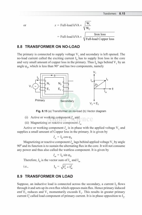
Transformers 8.15
or x = Full-load kVA × C
WW
i
= Full-load kVA × Iron loss
Full-load Copper loss
8.8 TRANSFORMER ON NO-LOAD
The primary is connected to supply voltage V1 and secondary is left opened. The no-load current called the exciting current I0 has to supply Iron loss in the core and very small amount of copper loss in the primary. Thus I0 lags behind V1 by an angle j0, which is less than 90° and has two components, namely
V1 ~
SecondaryPrimary
N1
E1
N2
E2
I0
I0
Im
Iw
V1
0
V = E2 2
Fig. 8.15 (a) Transformer on no-load (b) Vector diagram
(i) Active or working component Iw and(ii) Magnetizing or reactive component Im
Active or working component Iw is in phase with the applied voltage V1 and supplies a small amount of Copper loss in the primary. It is given by
Iw = I0 cos j0
Magnetizing or reactive component Im lags behind applied voltage V1 by angle 900 and its function is to sustain the alternating flux in the core. It will not consume any power and thus also called the wattless component. It is given by
Im = I0 sin j0
Therefore, I 0 is the vector sum of Iw and Im
i.e., I0 = 2 2I Iw m+
8.9 TRANSFORMER ON LOAD
Suppose, an inductive load is connected across the secondary, a current I2 flows through it and sets up its own flux which opposes main flux. Hence primary induced emf E1 reduces and V 1 momentarily exceeds E1. This results in greater primary current I1
1 called load component of primary current. It is in phase opposition to I2.
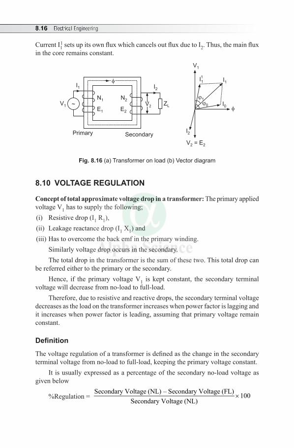
8.16 Electrical Engineering
Current I11 sets up its own flux which cancels out flux due to I2. Thus, the main flux
in the core remains constant.
V1 ~
SecondaryPrimary
N1
E1
N2
E2
I1 I1
V1
0
V = E2 2
V2ZL
I2
1
I0
I11
I2
Fig. 8.16 (a) Transformer on load (b) Vector diagram
8.10 VOLTAGE REGULATION
Concept of total approximate voltage drop in a transformer: The primary applied voltage V1 has to supply the following;(i) Resistive drop (I1 R1),(ii) Leakage reactance drop (I1 X1) and(iii) Has to overcome the back emf in the primary winding.
Similarly voltage drop occurs in the secondary. The total drop in the transformer is the sum of these two. This total drop can
be referred either to the primary or the secondary. Hence, if the primary voltage V1 is kept constant, the secondary terminal
voltage will decrease from no-load to full-load. Therefore, due to resistive and reactive drops, the secondary terminal voltage
decreases as the load on the transformer increases when power factor is lagging and it increases when power factor is leading, assuming that primary voltage remain constant.
Definition
The voltage regulation of a transformer is defined as the change in the secondary terminal voltage from no-load to full-load, keeping the primary voltage constant.
It is usually expressed as a percentage of the secondary no-load voltage as given below
%Regulation = Secondary Voltage (NL) – Secondary Voltage (FL) 100
Secondary Voltage (NL)×
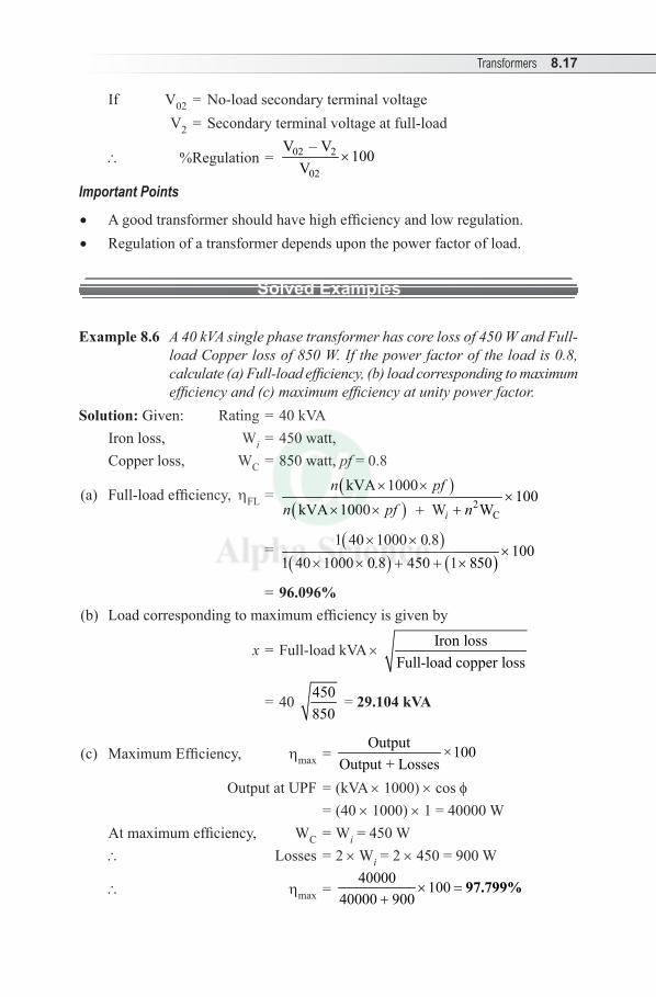
Transformers 8.17
If V02 = No-load secondary terminal voltage V2 = Secondary terminal voltage at full-load
\ %Regulation = 02 2
02
V – V 100V
×
Important Points
• A good transformer should have high efficiency and low regulation.• Regulation of a transformer depends upon the power factor of load.
Solved Examples
Example8.6 A 40 kVA single phase transformer has core loss of 450 W and Full-load Copper loss of 850 W. If the power factor of the load is 0.8, calculate (a) Full-load efficiency, (b) load corresponding to maximum efficiency and (c) maximum efficiency at unity power factor.
Solution: Given: Rating = 40 kVAIron loss, Wi = 450 watt,Copper loss, WC = 850 watt, pf = 0.8
(a) Full-load efficiency, hFL = ( )( ) 2
C
kVA 1000100
kVA 1000 W Wi
n pfn pf n
× ××
× × + +
= ( )( ) ( )
1 40 1000 0.8100
1 40 1000 0.8 450 1 850× ×
×× × + + ×
= 96.096%(b) Load corresponding to maximum efficiency is given by
x = Full-load kVA × Iron lossFull-load copper loss
= 40 450850
=29.104kVA
(c) Maximum Efficiency, hmax = Output ×100
Output + Losses Output at UPF = (kVA × 1000) × cos f = (40 × 1000) × 1 = 40000 W
At maximum efficiency, WC = Wi = 450 W\ Losses = 2 × Wi = 2 × 450 = 900 W
\ hmax = 40000 100
40000 900× =
+97.799%
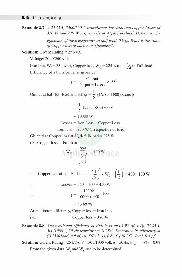
8.18 Electrical Engineering
Example8.7 A 25 kVA, 2000/200 V transformer has Iron and copper losses of 350 W and 225 W respectively at 3
4 th Full-load. Determine the
efficiency of the transformer at half load, 0.8 pf. What is the value of Copper loss at maximum efficiency?.
Solution: Given: Rating = 25 kVAVoltage: 2000/200 volt
Iron loss, Wi = 350 watt, Copper loss, WC = 225 watt at 34 th Full-load
Efficiency of a transformer is given by
h = Output 100Output + Losses
×
Output at half full-load and 0.8 pf = 12
(kVA × 1000) × cos f
= 12
(25 × 1000) × 0.8
= 10000 W Losses = Iron Loss + Copper Loss Iron loss = 350 W (Irrespective of load)Given that Copper loss at 3/4th full-load = 225 Wi.e., Copper loss at Full-load,
WC = 222534
= 400 W
\ Copper loss at half Full-load = 2 2
C1 1W 400 100 W2 2
× = × =
\ Losses = 350 + 100 = 450 W
\ h = 10000 100
10000 450×
+
= 95.69%At maximum efficiency, Copper loss = Iron lossi.e., Copper loss =350W
Example 8.8 The maximum efficiency at Full-load and UPF of a 1f, 25 kVA, 500/1000 V, 50 Hz transformer is 98%. Determine its efficiency at (i) 75% load, 0.9 pf, (ii) 50% load, 0.8 pf, (iii) 25% load, 0.6 pf.
Solution: Given: Rating = 25 kVA, V = 500/1000 volt, f = 50Hz, hmax = 98% = 0.98From the given data, Wi and WC are to be determined.
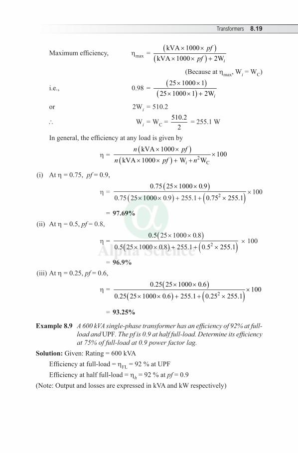
Transformers 8.19
Maximum efficiency, hmax = ( )
( )kVA 1000
kVA 1000 2Wi
pfpf
× ×× × +
(Because at hmax, Wi = WC)
i.e., 0.98 = ( )
( ) 25 1000 1
25 1000 1 2Wi
× ×× × +
or 2Wi = 510.2
\ Wi = WC = 510.22
= 255.1 W
In general, the efficiency at any load is given by
h = ( )
( ) 2C
kVA 1000100
kVA 1000 W Wi
n pfn pf n
× ××
× × + +
(i) At h = 0.75, pf = 0.9,
h = ( )
( ) ( )2
0.75 25 1000 0.9
0.75 25 1000 0.9 255.1 0.75 255.1
× ×
× × + + × × 100
= 97.69%(ii) At h = 0.5, pf = 0.8,
h = ( )
( ) ( )2
0.5 25 1000 0.8
0.5 25 1000 0.8 255.1 0.5 255.1
× ×
× × + + × × 100
= 96.9%(iii) At h = 0.25, pf = 0.6,
h = ( )
( ) ( )2
0.25 25 1000 0.6100
0.25 25 1000 0.6 255.1 0.25 255.1
× ××
× × + + ×
= 93.25%
Example 8.9 A 600 kVA single-phase transformer has an efficiency of 92% at full-load and UPF. The pf is 0.9 at half full-load. Determine its efficiency at 75% of full-load at 0.9 power factor lag.
Solution: Given: Rating = 600 kVA Efficiency at full-load = hFL = 92 % at UPF Efficiency at half full-load = hh = 92 % at pf = 0.9
(Note: Output and losses are expressed in kVA and kW respectively)
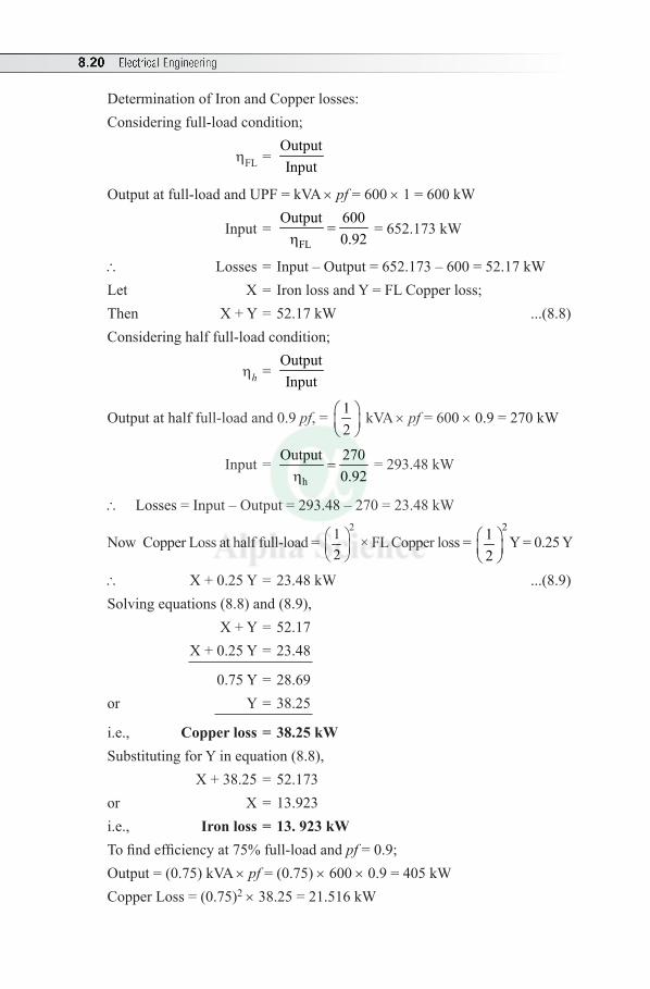
8.20 Electrical Engineering
Determination of Iron and Copper losses: Considering full-load condition;
hFL = OutputInput
Output at full-load and UPF = kVA × pf = 600 × 1 = 600 kW
Input = FL
Output 6000.92
=h
= 652.173 kW
\ Losses = Input – Output = 652.173 – 600 = 52.17 kWLet X = Iron loss and Y = FL Copper loss;Then X + Y = 52.17 kW ...(8.8)Considering half full-load condition;
hh = OutputInput
Output at half full-load and 0.9 pf, = 12
kVA × pf = 600 × 0.9 = 270 kW
Input = h
Output 2700.92
=h
= 293.48 kW
\ Losses = Input – Output = 293.48 – 270 = 23.48 kW
Now Copper Loss at half full-load = 21
2
× FL Copper loss = 21
2
Y = 0.25 Y
\ X + 0.25 Y = 23.48 kW ...(8.9)Solving equations (8.8) and (8.9), X + Y = 52.17 X + 0.25 Y = 23.48
0.75 Y = 28.69or Y = 38.25
i.e., Copperloss=38.25kW Substituting for Y in equation (8.8), X + 38.25 = 52.173or X = 13.923i.e., Ironloss=13.923kW To find efficiency at 75% full-load and pf = 0.9; Output = (0.75) kVA × pf = (0.75) × 600 × 0.9 = 405 kW Copper Loss = (0.75)2 × 38.25 = 21.516 kW
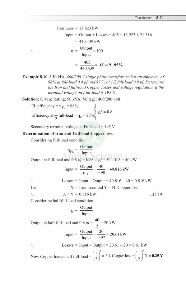
Transformers 8.21
Iron Loss = 13.923 kW Input = Output + Losses = 405 + 13.923 + 21.516 = 440.439 kW
\ h = Output 100Input
×
= 405 100440.439
× = 91.95%
Example 8.10 A 50 kVA, 400/200 V single phase transformer has an efficiency of 98% at full-load 0.8 pf and 97 % at 1/2 full-load 0.8 pf. Determine the Iron and full-load Copper losses and voltage regulation, if the terminal voltage on Full-load is 195 V.
Solution: Given: Rating: 50 kVA, Voltage: 400/200 volt
FLFL efficiency = = 98%,0.81Efficiency at full-load 97%
2 hpf
h =
= h =
Secondary terminal voltage at Full-load = 195 VDetermination of Iron and Full-load Copper loss:
Considering full-load condition;
hFL = OutputInput
Output at full-load and 0.8 pf = kVA × pf = 50 × 0.8 = 40 kW
Input = FL
Output 40 40.816 kW0.98
= =h
\ Losses = Input – Output = 40.816 – 40 = 0.816 kWLet X = Iron Loss and Y = FL Copper loss\ X + Y = 0.816 kW ...(8.10)Considering half full-load condition;
hh = OutputInput
Output at half full-load and 0.8 pf = 402
= 20 kW
Input = Output 20 20.61 kWInput 0.97
= =
\ Losses = Input – Output = 20.61 – 20 = 0.61 kW
Now Copper loss at half full-load = 2 21 1F.L Copper loss = Y
2 2 × =
0.25 Y

8.22 Electrical Engineering
\ X + 0.25 Y = Lossesi.e., X + 0.25 Y = 0.61 kW ...(8.11)Solving equations (8.10) and (8.11), X + Y = 0.816 X + 0.25Y = 0.61 0.75 Y = 0.206or Y = 0.27466
i.e., CopperLoss=0.2746kW=274.66WSubstituting for Y in equation (8.10), X + 0.27466 = 0.816or X = 0.54133i.e., IronLoss=0.5413kW=541.33W
Determination of voltage regulation:
% Regulation = 02 2
02
V – V ×100V
= 200 – 195 ×100
200= 2.5%
8.11 CONCEPT OF AUTOTRANSFORMER
It is a single winding transformer. The single winding is wound on a laminated core. The single winding acts as the primary and a part of it acts as the secondary.
Load
Supplyvoltage V1
V2
Fig. 8.17 Autotransformer
The winding is tapped at a suitable point to obtain the desired output voltage across the secondary.
Advantages
1. Requires less copper due to single winding.2. Smaller in size as compared with two winding transformers.3. It is more economical.4. Higher efficiency.
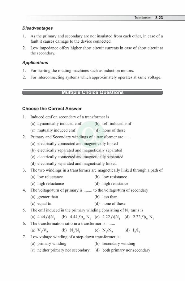
Transformers 8.23
Disadvantages
1. As the primary and secondary are not insulated from each other, in case of a fault it causes damage to the device connected.
2. Low impedance offers higher short circuit currents in case of short circuit at the secondary.
Applications
1. For starting the rotating machines such as induction motors.2. For interconnecting systems which approximately operates at same voltage.
Multiple Choice Questions
Choose the Correct Answer
1. Induced emf on secondary of a transformer is(a) dynamically induced emf (b) self induced emf(c) mutually induced emf (d) none of these
2. Primary and Secondary windings of a transformer are ......(a) electrically connected and magnetically linked(b) electrically separated and magnetically separated(c) electrically connected and magnetically separated(d) electrically separated and magnetically linked
3. The two windings in a transformer are magnetically linked through a path of(a) low reluctance (b) low resistance(c) high reluctance (d) high resistance
4. The voltage/turn of primary is ........ to the voltage/turn of secondary(a) greater than (b) less than(c) equal to (d) none of these
5. The emf induced in the primary winding consisting of N1 turns is(a) 4.44 f fN1 (b) 4.44 f fm N1 (c) 2.22 f fN1 (d) 2.22 f fm N1
6. The transformation ratio in a transformer is ........(a) V1/V2 (b) N2/N1 (c) N1 /N2 (d) I2/I1
7. Low voltage winding of a step-down transformer is(a) primary winding (b) secondary winding(c) neither primary nor secondary (d) both primary nor secondary
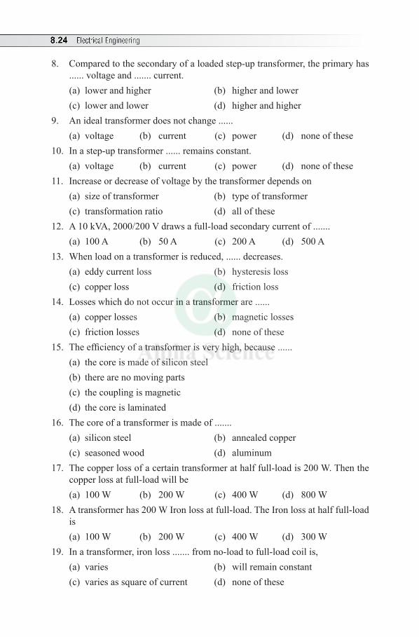
8.24 Electrical Engineering
8. Compared to the secondary of a loaded step-up transformer, the primary has ...... voltage and ....... current.(a) lower and higher (b) higher and lower(c) lower and lower (d) higher and higher
9. An ideal transformer does not change ......(a) voltage (b) current (c) power (d) none of these
10. In a step-up transformer ...... remains constant.(a) voltage (b) current (c) power (d) none of these
11. Increase or decrease of voltage by the transformer depends on(a) size of transformer (b) type of transformer(c) transformation ratio (d) all of these
12. A 10 kVA, 2000/200 V draws a full-load secondary current of .......(a) 100 A (b) 50 A (c) 200 A (d) 500 A
13. When load on a transformer is reduced, ...... decreases.(a) eddy current loss (b) hysteresis loss (c) copper loss (d) friction loss
14. Losses which do not occur in a transformer are ......(a) copper losses (b) magnetic losses(c) friction losses (d) none of these
15. The efficiency of a transformer is very high, because ......(a) the core is made of silicon steel(b) there are no moving parts(c) the coupling is magnetic(d) the core is laminated
16. The core of a transformer is made of .......(a) silicon steel (b) annealed copper(c) seasoned wood (d) aluminum
17. The copper loss of a certain transformer at half full-load is 200 W. Then the copper loss at full-load will be(a) 100 W (b) 200 W (c) 400 W (d) 800 W
18. A transformer has 200 W Iron loss at full-load. The Iron loss at half full-load is(a) 100 W (b) 200 W (c) 400 W (d) 300 W
19. In a transformer, iron loss ....... from no-load to full-load coil is,(a) varies (b) will remain constant(c) varies as square of current (d) none of these
Transformers 8.25
20. Transformer core is laminated in order to(a) simplify its construction (b) minimize eddy current loss(c) reduce cost (d) reduce hysteresis loss
21. When the load on the transformer is increased, the flux in the core ......(a) decreases (b) increases(c) remains constant (d) none of these
22. At maximum efficiency of a transformer(a) hysteresis loss = eddy current loss(b) iron loss = full-load copper loss(c) power factor of load is leading(d) power factor of load is lagging
23. A transformer is working at its maximum efficiency with iron-loss of 500 W, then its copper-loss will be(a) 500 W (b) 250 W (c) 300 W (d) 400 W
24. Regulation and efficiency of a transformer should be respectively(a) high, high (b) high, low (c) low, high (d) low, low
Answers:—
1. (c) 2. (d) 3. (a) 4. (c) 5. (b) 6. (b) 7. (b) 8. (a) 9. (c) 10. (c)
11. (d) 12. (b) 13. (c) 14. (c) 15. (b) 16. (a) 17. (d) 18. (b) 19. (b) 20. (b)
21. (c) 22. (b) 23. (a) 24. (c)
Review Questions
1. With a neat diagram describe the construction of a single-phase core type transformer.
2. With a neat diagram explain the construction and working principle of a single-phase transformer.
3. With neat sketches explain the constructional details of core type and shell type transformers.
4. Explain the principle of operation of a single-phase transformer and derive its emf equation.
5. What are the different losses that occur in a transformer? How do they vary with load? How are these losses minimized?
6. Explain various losses in a transformer and derive the condition for maximum efficiency.
8.26 Electrical Engineering
7. Develop an expression for the efficiency of a single-phase and obtain the condition for maximum efficiency.
8. Give the reasons for the following:(i) Iron loss remains the same irrespective of load on transformer with
constant supply.(ii) Efficiency of transformer is high compared to other electrical machines.(iii) Terminal voltage of transformer decreases with increase in load.(iv) The core of a transformer is made up of laminations.
9. Define voltage regulation of a transformer.10. Explain the construction of an autotransformer. Mention its advantages,
disadvantages and applications.
Exercises
1. A single-phase transformer has 350 primary turns and 1050 secondary turns. The net cross-sectional area of core is 55 cm2. If primary is connected to 400 V, 50 Hz. Find Bmax,voltage induced in the secondary.
(Ans: Bmax = 0.936 Wb/m2 , E2 = 1200 V)2. A 25 kVA, single-phase transformer has 500 turns on the primary and 40 turns
on the secondary winding. The primary is connected to 300 volt,50 Hz supply. Calculate (i) Primary and Secondary turns on full-load; (ii) The secondary emf; (iii) the maximum flux in the core.
(Ans: I1 = 8.33 A, I2 = 104.125 A, E2 = 240 V, fm = 0.27 Wb).
3. A single phase transformer has 1000 turns on its primary and 400 turns on the secondary side. An ac voltage of 1250 volt, 50 Hz is applied to its primary side, with the the secondary left open circuited, calculate (i) the secondary emf, (ii) maximum value of flux density, given that the effective cross section area of core as 60 cm2. (Ans: E2 = 500 V, Bm = 0.938 Tesla)
4. A 50 kVA transformer has an efficiency of 98% at full-load, 0.8 pf and an efficiency of 96.9% at ¼ full-load, UPF. Determine the Iron loss and the full-load Copper loss. (Ans:WC = 426 W and WI = 374 W)
5. A single-phase transformer working at UPF has an efficiency of 92% at both half-load and full-load of 500 kW. Determine the efficiency at 80% of full-load. (Ans: h = 97%)
6. Determine the efficiency of a 150 kVA transformer at 50% full-load of 0.8 pf lag, if the Copper loss at full-load is 1600 W and the Iron loss 1400 W.
(Ans:h = 97%)
Transformers 8.27
7. In a 25 kVA, 2000/200 V transformer, the Iron and full-load Copper losses are 350 W and 400 W respectively. Calculate the efficiency at UPF at full-load and half full-load. Find also Copper loss for maximum efficiency.
(Ans: 96.52% and 350 W) 8. A 600 kVA single-phase transformer has an efficiency of 92% both at full-load
and half full-load at UPF. Determine its efficiency at 75% of full-load at 0.9 power factor lag. (Ans:91.63%)
9.1 PRINCIPLE OF OPERATION
Synchronous generator or alternator or ac generator is a machine, which converts mechanical energy into electrical energy.
In commercial alternator, armature is stationary, and as field is rotating. As the field system rotates, the stationary armature conductors are cut by the flux and alternating emf is induced in it according to Faraday’s Laws of EMI. For bulk power generation (e.g., 11 kVA, 500 MW) three phase alternators are used. Advantages of Stationary Armature:(i) Easy to insulate the stationary armature conductors as alternators are designed
to generate high voltage.(ii) The output terminals can be directly connected to the load without any slip
rings and brushes. (iii) Gives good mechanical support.(iv) The rotor can be rotated at high speed as it is robust in construction.Comparison between DC Generator and Alternator:Similarity: DC Generator and Alternator operate on Faraday’s Laws of EMI.Differences: In dc generator, field is stationary and armature is rotating. The output is supplied to load circuit by means of commutator and brushes. In alternator, the field is rotating called the rotor and the armature is stationary called the stator. The output is directly connected to load.
9.2 CONSTRUCTION
Commercial alternator consists of mainly two parts1. Stationary armature called Stator and2. Rotating field called Rotor.
Synchronous Generators9
Chapter
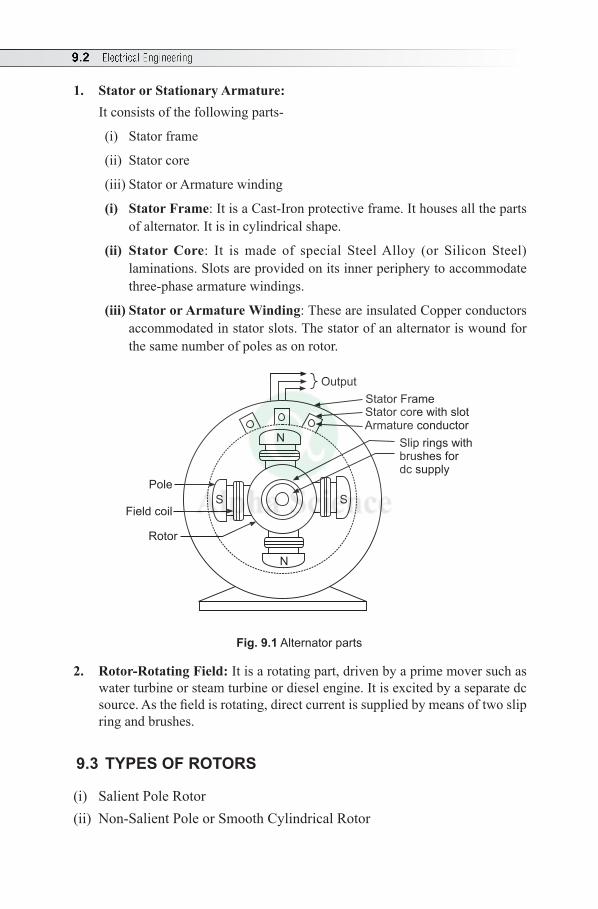
9.2 Electrical Engineering
1. Stator or Stationary Armature:It consists of the following parts-
(i) Stator frame
(ii) Stator core
(iii) Stator or Armature winding
(i) Stator Frame: It is a Cast-Iron protective frame. It houses all the parts of alternator. It is in cylindrical shape.
(ii) Stator Core: It is made of special Steel Alloy (or Silicon Steel)laminations. Slots are provided on its inner periphery to accommodate three-phase armature windings.
(iii) Stator or Armature Winding: These are insulated Copper conductors accommodated in stator slots. The stator of an alternator is wound for the same number of poles as on rotor.
Field coil
Output
Stator FrameStator core with slotArmature conductor
Slip rings withbrushes fordc supply
N
N
SS
Pole
Rotor
Fig. 9.1 Alternator parts
2. Rotor-Rotating Field: It is a rotating part, driven by a prime mover such as water turbine or steam turbine or diesel engine. It is excited by a separate dc source. As the field is rotating, direct current is supplied by means of two slip ring and brushes.
9.3 TYPES OF ROTORS
(i) Salient Pole Rotor (ii) Non-Salient Pole or Smooth Cylindrical Rotor
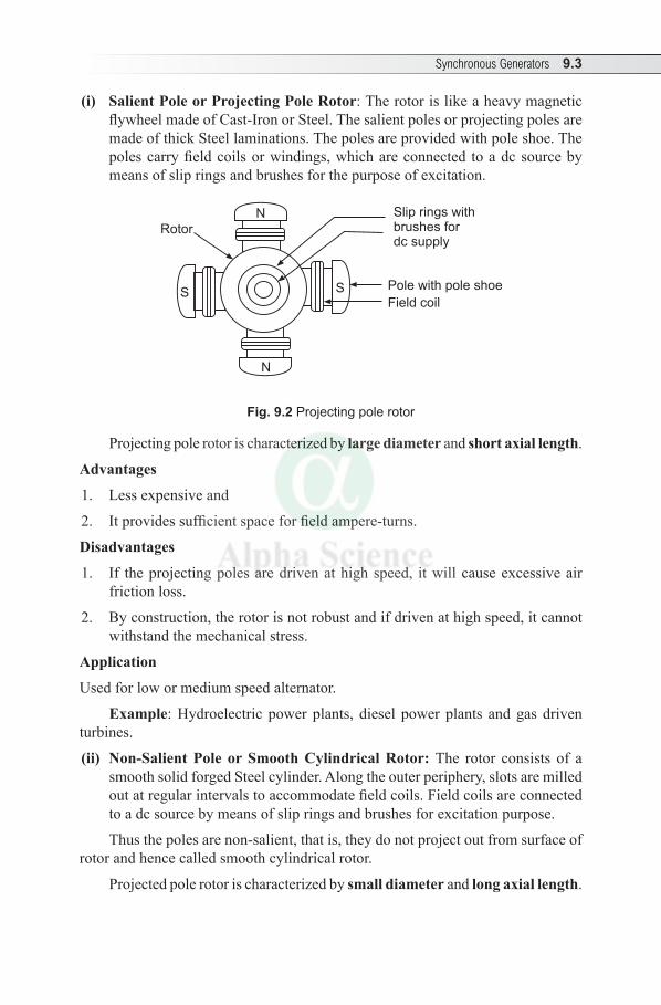
Synchronous Generators 9.3
(i) Salient Pole or Projecting Pole Rotor: The rotor is like a heavy magnetic flywheel made of Cast-Iron or Steel. The salient poles or projecting poles are made of thick Steel laminations. The poles are provided with pole shoe. The poles carry field coils or windings, which are connected to a dc source by means of slip rings and brushes for the purpose of excitation.
Slip rings withbrushes fordc supply
N
SS
Rotor
Pole with pole shoe
Field coil
N
Fig. 9.2 Projecting pole rotor
Projecting pole rotor is characterized by large diameter and short axial length.
Advantages
1. Less expensive and
2. It provides sufficient space for field ampere-turns.
Disadvantages
1. If the projecting poles are driven at high speed, it will cause excessive air friction loss.
2. By construction, the rotor is not robust and if driven at high speed, it cannot withstand the mechanical stress.
Application
Used for low or medium speed alternator.
Example: Hydroelectric power plants, diesel power plants and gas driven turbines.
(ii) Non-Salient Pole or Smooth Cylindrical Rotor: The rotor consists of a smooth solid forged Steel cylinder. Along the outer periphery, slots are milled out at regular intervals to accommodate field coils. Field coils are connected to a dc source by means of slip rings and brushes for excitation purpose.
Thus the poles are non-salient, that is, they do not project out from surface of rotor and hence called smooth cylindrical rotor.
Projected pole rotor is characterized by small diameter and long axial length.
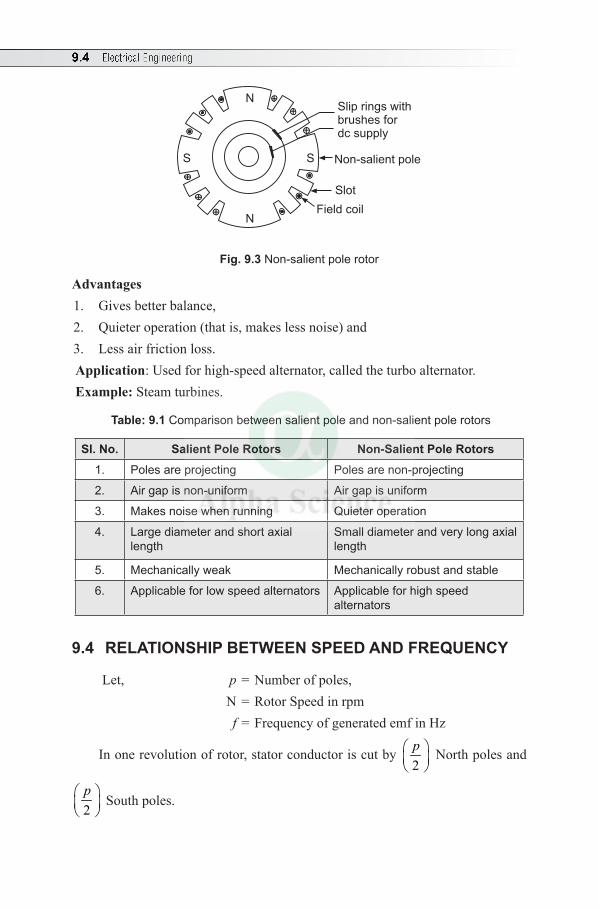
9.4 Electrical Engineering
S
N
N
S
++
+
+
+
+
Slip rings withbrushes fordc supply
Slot
Field coil
Non-salient pole
Fig. 9.3 Non-salient pole rotor
Advantages 1. Gives better balance, 2. Quieter operation (that is, makes less noise) and 3. Less air friction loss. Application: Used for high-speed alternator, called the turbo alternator. Example: Steam turbines.
Table: 9.1 Comparison between salient pole and non-salient pole rotors
SI. No. Salient Pole Rotors Non-Salient Pole Rotors1. Poles are projecting Poles are non-projecting
2. Air gap is non-uniform Air gap is uniform
3. Makes noise when running Quieter operation
4. Large diameter and short axial length
Small diameter and very long axial length
5. Mechanically weak Mechanically robust and stable
6. Applicable for low speed alternators Applicable for high speed alternators
9.4 RELATIONSHIP BETWEEN SPEED AND FREQUENCY
Let, p = Number of poles, N = Rotor Speed in rpm f = Frequency of generated emf in Hz
In one revolution of rotor, stator conductor is cut by 2p
North poles and
2p
South poles.
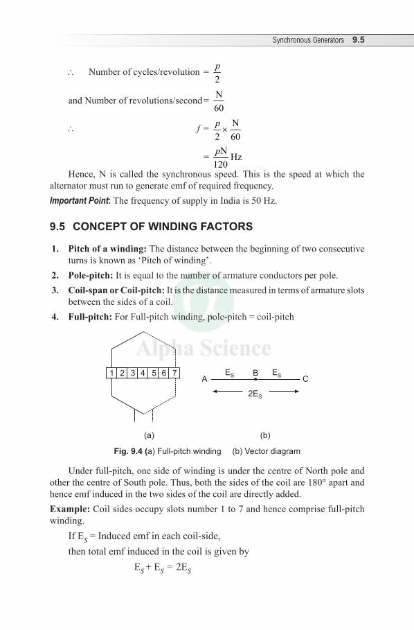
Synchronous Generators 9.5
\ Number of cycles/revolution = 2p
and Number of revolutions/second = N60
\ f = N2 60p×
= N Hz120p
Hence, N is called the synchronous speed. This is the speed at which the alternator must run to generate emf of required frequency.Important Point: The frequency of supply in India is 50 Hz.
9.5 CONCEPT OF WINDING FACTORS
1. Pitch of a winding: The distance between the beginning of two consecutive turns is known as ‘Pitch of winding’.
2. Pole-pitch: It is equal to the number of armature conductors per pole. 3. Coil-span or Coil-pitch: It is the distance measured in terms of armature slots
between the sides of a coil. 4. Full-pitch: For Full-pitch winding, pole-pitch = coil-pitch
2ES
ES ESC
BA
1 2 3 4 5 6 7
(a) (b)
Fig. 9.4 (a) Full-pitch winding (b) Vector diagram
Under full-pitch, one side of winding is under the centre of North pole and other the centre of South pole. Thus, both the sides of the coil are 180° apart and hence emf induced in the two sides of the coil are directly added.Example: Coil sides occupy slots number 1 to 7 and hence comprise full-pitch winding.
If ES = Induced emf in each coil-side, then total emf induced in the coil is given by ES + ES = 2ES
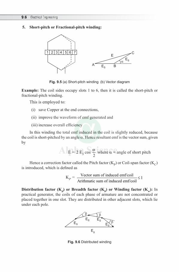
9.6 Electrical Engineering
5. Short-pitch or Fractional-pitch winding:
C
BA
1 2 3 4 5 6 7
ES
ES
E
Fig. 9.5 (a) Short-pitch winding (b) Vector diagram
Example: The coil sides occupy slots 1 to 6, then it is called the short-pitch or fractional-pitch winding.
This is employed to:
(i) save Copper at the end connections,
(ii) improve the waveform of emf generated and
(iii) increase overall efficiency
In this winding the total emf induced in the coil is slightly reduced, because the coil is short-pitched by an angle a. Hence resultant emf is the vector sum, given by
E = 2 ES cos 2a where a = angle of short pitch
Hence a correction factor called the Pitch factor (KP) or Coil-span factor (KC) is introduced, which is defined as
KP = Vector sum of induced emf/coil 1Arithmatic sum of induced emf/coil
≤
Distribution factor (Kd) or Breadth factor (Kb) or Winding factor (Kw): In practical generator, the coils of each phase of armature are not concentrated or placed together in one slot. They are distributed in other adjacent slots, which lie under each pole.
ES
ES ES
ES
Eg
Fig. 9.6 Distributed winding
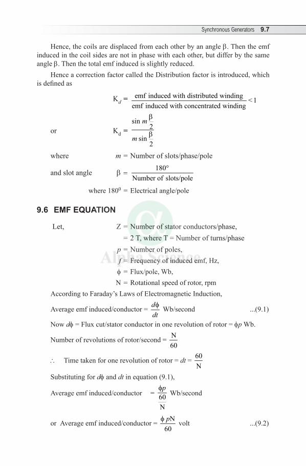
Synchronous Generators 9.7
Hence, the coils are displaced from each other by an angle b. Then the emf induced in the coil sides are not in phase with each other, but differ by the same angle b. Then the total emf induced is slightly reduced.
Hence a correction factor called the Distribution factor is introduced, which is defined as
Kd = emf induced with distributed winding < 1emf induced with concentrated winding
or Kd = sin
2
sin2
m
m
b
b
where m = Number of slots/phase/pole
and slot angle b=180°
Number of slots/pole
where 1800 = Electrical angle/pole
9.6 EMF EQUATION
Let, Z = Number of stator conductors/phase, = 2 T, where T = Number of turns/phase p = Number of poles, f = Frequency of induced emf, Hz, f = Flux/pole, Wb, N = Rotational speed of rotor, rpmAccording to Faraday’s Laws of Electromagnetic Induction,
Average emf induced/conductor = ddtf Wb/second ...(9.1)
Now df = Flux cut/stator conductor in one revolution of rotor = fp Wb.
Number of revolutions of rotor/second = N60
\ Time taken for one revolution of rotor = dt = 60N
Substituting for df and dt in equation (9.1),
Average emf induced/conductor = 60N
pf Wb/second
or Average emf induced/conductor = N60pf volt ...(9.2)
9.8 Electrical Engineering
Frequency of induced emf is given by
f = N120p Hz
or N = 120 fp
Substituting for N in equation (9.2),
Average emf induced/conductor = 12060
p fp
f× = 2ff volt
For Z number of stator conductors in series, Average emf induced/phase = 2 f f Z = 2 f f × 2 T (because Z = 2T) = 4 f f T volt
RMS value of induced emf/phase = Average emf induced/phase × form factor = 4 f f T × 1.11 = 4.44 f f T volt The actual induced emf/phase available is given by introducing Pitch factor
(Kp) and Distribution factor (Kd), Eph = 4.44 f f T KP Kd voltIf the alternator is star-connected, then Line emf is given by EL = 3 Eph volt
Solved Examples
Example 9.1 A 12 pole,500 rpm, Y-connected alternator has 60 slots with 20 conductors per slot. The flux per pole is 0.02 Wb and is distributed sinusoidally. The winding factor is 0.97. Calculate (i) frequency (ii) phase emf and (iii) line emf.
Solution: Given: p = 12, N = 500 rpm, Number of slots = 60, Number of conductors/slot = 20 f = 0.02 Wb., Kw = 0.97
Frequency, f = N 12 500120 120p ×
= = 50 Hz
Phase emf, Eph = 4.44 f f T KP Kw Z = number of stator conductors/phase = Number of slots/phase × Number of conductors/slot
= 60 20 4003× =
Synchronous Generators 9.9
\ T = 400 200
2 2Z= =
Assuming pitch factor, Kp = 1, Eph = 4.44 × 0.02 × 50 × 200 × 1 × 0.97
= 861.36 V
Line emf, EL = 3 E ph×
= 3 × 861.36 = 1491.92 V
Example 9.2 A 2 pole, three-phase alternator running at 3000 rpm has 42 armature slots with 2 conductors in each slot. Calculate the flux per pole required to generate a line voltage of 2300 V. Distribution factor is 0.952 and pitch factor is 0.956.
Solution: Given: p = 2, N = 3000 rpm, Number of slots = 42, Number of conductors/slot = 2
EL = 2300 V, Kd = 0.952 and KP = 0.956 Eph = 4.44 f f T KP Kd
or f = E
4.44 T Kph
P df K
Now Eph = E 23003 3L = = 1327.9V
Frequency, f = N 2 3000120 120p ×
= = 50 Hz
To find T: Z = number of stator conductors/phase = Number of slots/phase × Number of conductors / slot
= 42 2 283× =
\ T = 28 14
2 2Z= =
\ f = 1327.94.44 50 14 0.956 0.952
=× × × ×
0.469 Wb
Example 9.3 A three-phase star connected synchronous generator driven at 900 r/min is required to generate a line voltage of 460 V at 60 Hz on open circuit. The stator has two slots per pole per phase and 4 conductors per slot. Calculate (i) the number of poles and (ii) the useful flux per pole.
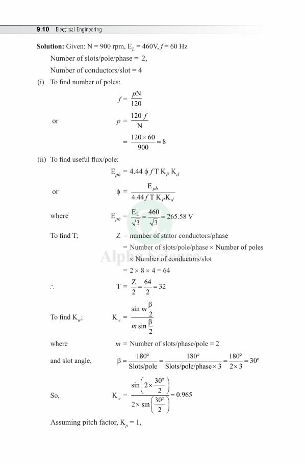
9.10 Electrical Engineering
Solution: Given: N = 900 rpm, EL = 460V, f = 60 Hz
Number of slots/pole/phase = 2,Number of conductors/slot = 4
(i) To find number of poles:
f = N
120p
or p = 120
Nf
= 120 60 8
900×
=
(ii) To find useful flux/pole:
Eph = 4.44 f f T KP Kd
or f = E
4.44 T K Kph
P df
where Eph = LE 460 265.58 V3 3= =
To find T; Z = number of stator conductors/phase = Number of slots/pole/phase × Number of poles ×Number of conductors/slot = 2 × 8 × 4 = 64
\ T = Z 64 322 2= =
To find Kw; Kw = sin
2
sin2
m
m
b
b
where m = Number of slots/phase/pole = 2
and slot angle, 180 180 180 30Slots/pole Slots/pole/phase 3 2 3
° ° °b = = = = °
× ×
So, Kw =
30sin 22 0.965
302 sin2
° × =
° ×
Assuming pitch factor, Kp = 1,
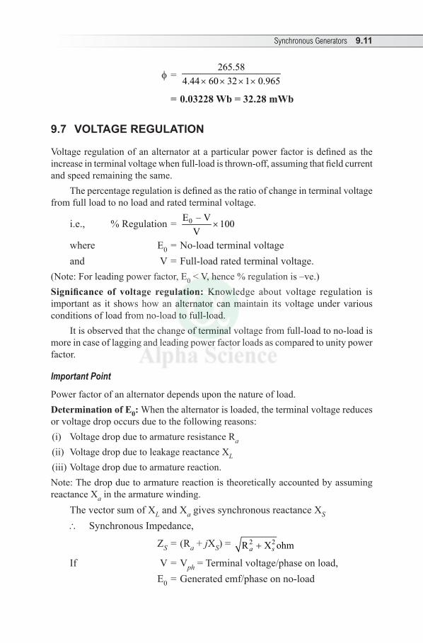
Synchronous Generators 9.11
f = 265.58
4.44 60 32 1 0.965× × × ×
= 0.03228 Wb = 32.28 mWb
9.7 VOLTAGE REGULATION
Voltage regulation of an alternator at a particular power factor is defined as the increase in terminal voltage when full-load is thrown-off, assuming that field current and speed remaining the same.
The percentage regulation is defined as the ratio of change in terminal voltage from full load to no load and rated terminal voltage.
i.e., % Regulation = 0E – V 100V
×
where E0 = No-load terminal voltageand V = Full-load rated terminal voltage.
(Note: For leading power factor, E0 < V, hence % regulation is –ve.)Significance of voltage regulation: Knowledge about voltage regulation is important as it shows how an alternator can maintain its voltage under various conditions of load from no-load to full-load.
It is observed that the change of terminal voltage from full-load to no-load is more in case of lagging and leading power factor loads as compared to unity power factor.
Important Point
Power factor of an alternator depends upon the nature of load.Determination of E0: When the alternator is loaded, the terminal voltage reduces or voltage drop occurs due to the following reasons:(i) Voltage drop due to armature resistance Ra
(ii) Voltage drop due to leakage reactance XL
(iii) Voltage drop due to armature reaction. Note: The drop due to armature reaction is theoretically accounted by assuming reactance Xa in the armature winding.
The vector sum of XL and Xa gives synchronous reactance XS \ Synchronous Impedance,
ZS = (Ra + jXS) = 2 2R X ohma s+
If V = Vph = Terminal voltage/phase on load, E0 = Generated emf/phase on no-load
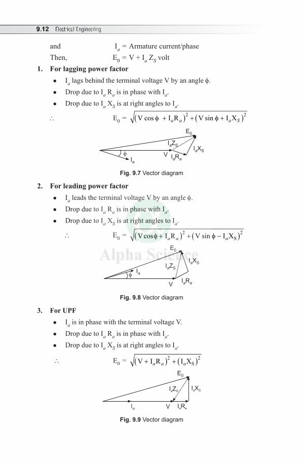
9.12 Electrical Engineering
and Ia = Armature current/phase Then, E0 = V + Ia ZS volt
1. For lagging power factorl Ia lags behind the terminal voltage V by an angle f.l Drop due to Ia Ra is in phase with Ia.l Drop due to Ia XS is at right angles to Ia.
\ E0 = ( ) ( )2 2V cos I R V sin I Xa a a Sf + + f +
E0
I Xa S
I Ra a
I Za S
Ia
V
Fig. 9.7 Vector diagram
2. For leading power factorl Ia leads the terminal voltage V by an angle f.l Drop due to Ia Ra is in phase with Ia.l Drop due to Ia XS is at right angles to Ia.
\ E0 = ( ) ( )2 2SV cos I R V sin I Xa a af + + f −
I Ra a
I Xa SI Za S
E0
V
Fig. 9.8 Vector diagram
3. For UPFl Ia is in phase with the terminal voltage V. l Drop due to Ia Ra is in phase with Ia.l Drop due to Ia XS is at right angles to Ia.
\ E0 = ( ) ( )2 2SV I R I Xa a a+ +
I Xa SI Za S
I Ra a
E0
V
Fig. 9.9 Vector diagram

Synchronous Generators 9.13
Multiple Choice Questions
Choose the Correct Answer
1. Alternator generates ......... voltage(a) ac (b) dc(c) Both ac and dc (d) none of these
2. A commercial alternator has(a) rotating armature and stationary field(b) stationary armature and rotating field(c) both armature and field are rotating(d) both armature and field are stationary
3. The stator of an alternator is wound for ......... as on rotor.(a) more number of poles than (b) less number of poles than (c) the same number of poles (d) none of these
4. The rotor of synchronous generator has(a) 4 slip rings (b) 3 slip rings(c) 2 slip rings (d) no slip rings
5. The field winding of an alternator is ......... excited(a) dc (b) ac(c) both ac and dc (d) none of these
6. A salient pole field construction is used for alternator having ........(a) low and medium speed (b) large speed(c) very large speed (d) none of these
7. Salient pole type rotors are(a) smaller in axial length(b) larger in axial length (c) smaller diameter(d) larger diameter and smaller in axial length
8. High speed alternators are driven by(a) diesel engine (b) hydraulic turbines(c) steam turbines (d) none of these
9. For full-pitch coil, the pitch factor KP is ..........(a) 1 (b) >1(c) < 1 (d) none of these
9.14 Electrical Engineering
10. Usually modern alternators have short pitched windings so as to (a) increase the machine rating (b) improve the voltage waveform (c) improve generated voltage (d) none of these
11. Distribution factor is always(a) equal to one (b) more than one(c) zero (d) less than one
12. Distribution factor for a winding having 3 slots/pole/phase and a slot angle of 20 degrees is .......(a) 0.96 (b) 1 (c) 0.5 (d) 0.707
13. The disadvantage of a short-pitched coil in an alternator is that(a) harmonica are introduced (b) wave form become non sinusoidal (c) voltage round the coil is reduced (d) none of these
14. A 6 pole 50 Hz synchronous machine runs at(a) 750 rpm (b) 1000 rpm(c) 1500 rpm (d) 1440 rpm
15. The frequency of induced emf generated depends on (a) speed (b) number of poles(c) flux (d) both (a) and (b)
16. The frequency of supply in India is (a) 60 Hz (b) 25 Hz (c) 50 Hz (d) 75 Hz
17. A 50 Hz alternator will run at the greatest possible speed if it is wound for ........ poles(a) 8 (b) 6 (c) 4 (d) 2
18. The highest speed at which a 50 Hz AC Generator can be operated is(a) 3000 rpm (b) 1500 rpm (c) 3600 rpm (d) 1800 rpm
19. The number of cycles generated in a 6 pole alternator in one revolution is(a) 3 (b) 6 (c) 50 (d) 2
20. If the alternator runs at a speed N rpm, then the time taken for 1 revolution is (a) N/60 sec (b) 60/N sec (c) 60N sec (d) none of these
21. When the alternator is loaded, its terminal voltage ........(a) increases (b) decreases(c) does not change (d) none of these
Synchronous Generators 9.15
22. The power factor of an alternator is determined by its(a) speed (b) load (c) excitation (d) prime mover
Answers:—
1. (a) 2. (b) 3. (c) 4. (c) 5. (a) 6. (a) 7. (d) 8. (c) 9. (a) 10. (b)
11. (d) 12. (a) 13. (c) 14. (b) 15. (d) 16. (c) 17. (d) 18. (a) 19. (a) 20. (b)
21. (b) 22. (b)
Review Questions
1. With neat diagram, explain the constructional features of a three-phase alternator.
2. What are the advantages of stationary armature in alternator?3. What are the advantages of rotating field synchronous generator?4. List the differences between salient pole and non-salient pole rotors.5. Bring out the comparison between a dc generator and an alternator?6. Derive the emf equation of an alternator. What is the necessity of considering
pitch factor and distribution factor for emf equation?7. With usual notations, obtain the relationship between speed and frequency.
Exercises
1. A three-phase star-connected alternator with 12-poles generates 1100 volt on open circuit at a speed of 500 rpm. Assuming 180 turns/phase, a distribution factor of 0.96 and full-pitched coils, find the useful flux per pole.
(Ans: f = 0.0165 Wb)2. Calculate the phase emf induced in a 4-pole, three-phase, 50 Hz, star-connected
alternator with 36 slots and 30 conductors per slot. The flux per pole is 0.05 weber. Assume winding factor of 0.95. (Ans: Eph = 1898 V)
3. Calculate the line emf induced in a 4-pole, three-phase, 50 Hz star-connected alternator with 48 slots and 20 conductors per slot. The flux per pole is 0.05 weber, assume winding factor 0.96. (Ans: EL = 2953 V)
4. A 6 pole, three-phase, star-connected alternator has an armature with 90 slots and 8 conductors per slot. It revolves at 1000 rpm. The flux per pole being 0.05 weber. Calculate the emf generated if the winding factor is 0.97 and all the conductors in each phase are in series.
(Ans: Eph = 1292 V and EL = 2237.8 V)
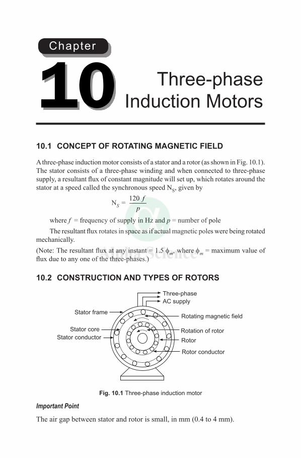
10.1 CONCEPT OF ROTATING MAGNETIC FIELD
A three-phase induction motor consists of a stator and a rotor (as shown in Fig. 10.1). The stator consists of a three-phase winding and when connected to three-phase supply, a resultant flux of constant magnitude will set up, which rotates around the stator at a speed called the synchronous speed NS, given by
NS = 120 fp
where f = frequency of supply in Hz and p = number of pole The resultant flux rotates in space as if actual magnetic poles were being rotated
mechanically. (Note: The resultant flux at any instant = 1.5 fm, where fm = maximum value of flux due to any one of the three-phases.)
10.2 CONSTRUCTION AND TYPES OF ROTORS
Three-phase
AC supply
Stator frame
Rotor
Rotating magnetic field
Rotation of rotorStator conductor
Rotor conductor
Stator core
Fig. 10.1 Three-phase induction motor
Important Point
The air gap between stator and rotor is small, in mm (0.4 to 4 mm).
Three-phase Induction Motors10
Chapter
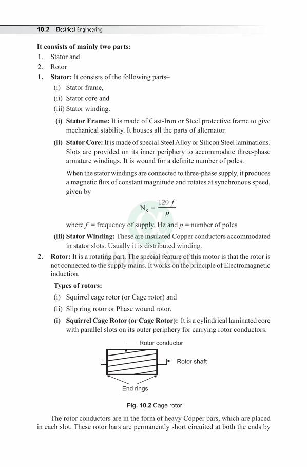
10.2 Electrical Engineering
It consists of mainly two parts:1. Stator and2. Rotor1. Stator: It consists of the following parts–
(i) Stator frame, (ii) Stator core and(iii) Stator winding.
(i) Stator Frame: It is made of Cast-Iron or Steel protective frame to give mechanical stability. It houses all the parts of alternator.
(ii) Stator Core: It is made of special Steel Alloy or Silicon Steel laminations. Slots are provided on its inner periphery to accommodate three-phase armature windings. It is wound for a definite number of poles.
When the stator windings are connected to three-phase supply, it produces a magnetic flux of constant magnitude and rotates at synchronous speed, given by
NS = 120 f
p
where f = frequency of supply, Hz and p = number of poles (iii) Stator Winding: These are insulated Copper conductors accommodated
in stator slots. Usually it is distributed winding.2. Rotor: It is a rotating part. The special feature of this motor is that the rotor is
not connected to the supply mains. It works on the principle of Electromagnetic induction. Types of rotors:(i) Squirrel cage rotor (or Cage rotor) and(ii) Slip ring rotor or Phase wound rotor.(i) Squirrel Cage Rotor (or Cage Rotor): It is a cylindrical laminated core
with parallel slots on its outer periphery for carrying rotor conductors.
End rings
Rotor shaft
Rotor conductor
Fig. 10.2 Cage rotor
The rotor conductors are in the form of heavy Copper bars, which are placed in each slot. These rotor bars are permanently short circuited at both the ends by
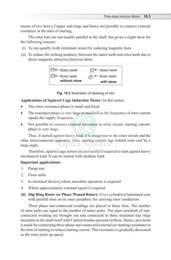
Three-phase Induction Motors 10.3
means of two heavy Copper end-rings and hence not possible to connect external resistance at the time of starting.
The rotor bars are not usually parallel to the shaft, but given a slight skew for the following reasons: (i) To run quietly (with minimum noise) by reducing magnetic hum.(ii) To reduce the locking tendency between the stator teeth and rotor teeth due to
direct magnetic attraction between them.
Stator teeth
Rotor teeth
Stator teeth
Rotor teeth
without skew with skew
Fig. 10.3 Illustration of skewing of slot
Applications of Squirrel Cage Induction Motor: In this motor,• The rotor resistance/phase is small and fixed. • The reactance/phase is very large at standstill as the frequency of rotor current
equals the supply frequency. • Not possible to connect external resistance to rotor circuit, starting current/
phase is very large. Thus, if started against heavy load, it is dangerous to the rotor circuit and the
other interconnected apparatus. Also, starting current lags behind rotor emf by a large angle.
Therefore, squirrel cage motors are not useful if required to start against heavy mechanical load. It can be started with medium load.Important applications:1. Pump sets2. Floor mills3. In electrical devices where smoother operation is required 4. Where approximately constant speed is required(ii) Slip Ring Rotor (or Phase Wound Rotor): It is a cylindrical laminated core
with parallel slots on its outer periphery for carrying rotor conductors. Three phase star-connected windings are placed in these slots. The number
of rotor poles are equal to the number of stator poles. The open terminals of star-connected winding are brought out and connected to three insulated slip rings mounted on the shaft itself with Carbon brushes pressed on them. Hence, provision is made for connecting three-phase star-connected external (or starting) resistance at the time of starting to reduce starting current. This resistance is gradually decreased as the rotor picks up speed.
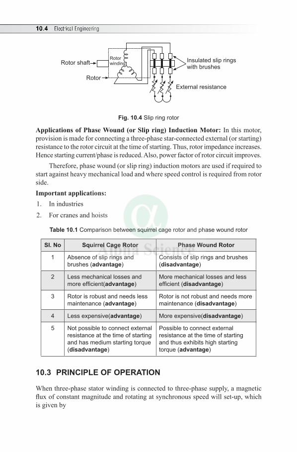
10.4 Electrical Engineering
Insulated slip ringswith brushes
External resistance
Rotor
Rotor shaftRotorwinding
Fig. 10.4 Slip ring rotor
Applications of Phase Wound (or Slip ring) Induction Motor: In this motor, provision is made for connecting a three-phase star-connected external (or starting) resistance to the rotor circuit at the time of starting. Thus, rotor impedance increases.Hence starting current/phase is reduced. Also, power factor of rotor circuit improves.
Therefore, phase wound (or slip ring) induction motors are used if required to start against heavy mechanical load and where speed control is required from rotor side. Important applications:1. In industries2. For cranes and hoists
Table 10.1 Comparison between squirrel cage rotor and phase wound rotor
SI. No Squirrel Cage Rotor Phase Wound Rotor
1 Absence of slip rings and brushes (advantage)
Consists of slip rings and brushes (disadvantage)
2 Less mechanical losses and more efficient(advantage)
More mechanical losses and less efficient (disadvantage)
3 Rotor is robust and needs less maintenance (advantage)
Rotor is not robust and needs more maintenance (disadvantage)
4 Less expensive(advantage) More expensive(disadvantage)
5 Not possible to connect external resistance at the time of starting and has medium starting torque (disadvantage)
Possible to connect external resistance at the time of starting and thus exhibits high starting torque (advantage)
10.3 PRINCIPLE OF OPERATION
When three-phase stator winding is connected to three-phase supply, a magnetic flux of constant magnitude and rotating at synchronous speed will set-up, which is given by
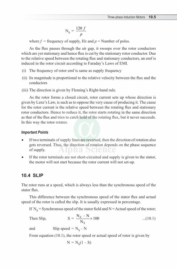
Three-phase Induction Motors 10.5
NS = 120 fp
where f = frequency of supply, Hz and p = Number of poles.
As the flux passes through the air gap, it sweeps over the rotor conductors which are yet stationary and hence flux is cut by the stationary rotor conductor. Due to the relative speed between the rotating flux and stationary conductors, an emf is induced in the rotor circuit according to Faraday’s Laws of EMI.
(i) The frequency of rotor emf is same as supply frequency
(ii) Its magnitude is proportional to the relative velocity between the flux and the conductors
(iii) The direction is given by Fleming’s Right-hand rule.
As the rotor forms a closed circuit, rotor current sets up whose direction is given by Lenz’s Law, is such as to oppose the very cause of producing it. The cause for the rotor current is the relative speed between the rotating flux and stationary rotor conductors. Hence to reduce it, the rotor starts rotating in the same direction as that of the flux and tries to catch hold of the rotating flux, but it never succeeds. In this way the rotor rotates.
Important Points
• If two terminals of supply lines are reversed, then the direction of rotation also gets reversed. Thus, the direction of rotation depends on the phase sequence of supply.
• If the rotor terminals are not short-circuited and supply is given to the stator, the motor will not start because the rotor current will not set-up.
10.4 SLIP
The rotor runs at a speed, which is always less than the synchronous speed of the stator flux.
This difference between the synchronous speed of the stator flux and actual speed of the rotor is called the slip. It is usually expressed in percentage.
If NS = Synchronous speed of the stator field and N = Actual speed of the rotor;
Then Slip, S = N – N 100NS
S× ...(10.1)
and Slip speed = NS – N
From equation (10.1), the rotor speed or actual speed of rotor is given by
N = NS(1 – S)
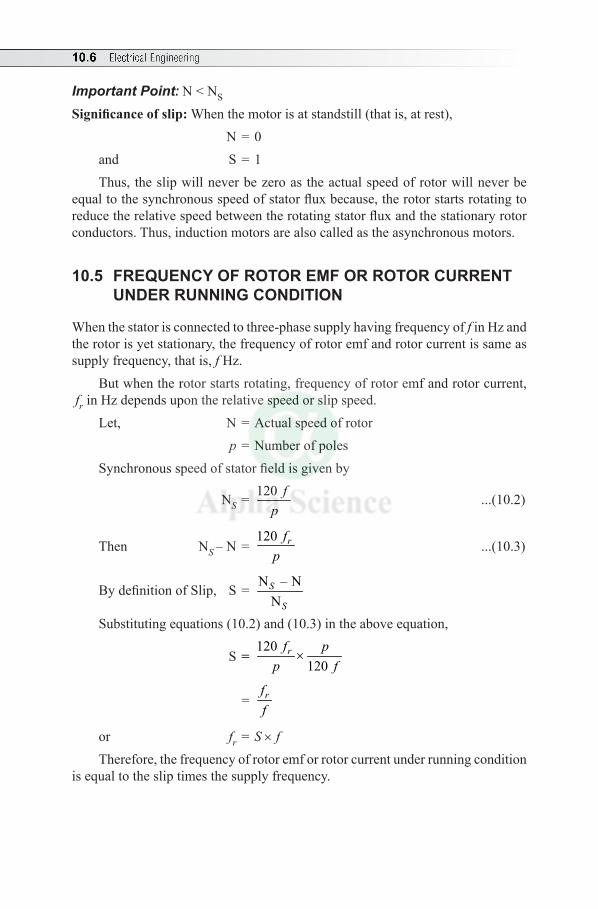
10.6 Electrical Engineering
Important Point: N < NS
Significance of slip: When the motor is at standstill (that is, at rest), N = 0 and S = 1Thus, the slip will never be zero as the actual speed of rotor will never be
equal to the synchronous speed of stator flux because, the rotor starts rotating to reduce the relative speed between the rotating stator flux and the stationary rotor conductors. Thus, induction motors are also called as the asynchronous motors.
10.5 FREQUENCY OF ROTOR EMF OR ROTOR CURRENT UNDER RUNNING CONDITION
When the stator is connected to three-phase supply having frequency of f in Hz and the rotor is yet stationary, the frequency of rotor emf and rotor current is same as supply frequency, that is, f Hz.
But when the rotor starts rotating, frequency of rotor emf and rotor current, fr in Hz depends upon the relative speed or slip speed.
Let, N = Actual speed of rotor p = Number of poles Synchronous speed of stator field is given by
NS = 120 fp
...(10.2)
Then NS – N = 120 rf
p ...(10.3)
By definition of Slip, S = N – NNS
S
Substituting equations (10.2) and (10.3) in the above equation,
S = 120
120rf p
p f×
= rff
or fr = S × fTherefore, the frequency of rotor emf or rotor current under running condition
is equal to the slip times the supply frequency.
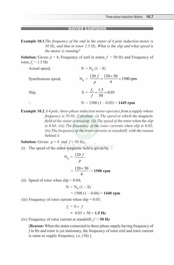
Three-phase Induction Motors 10.7
Solved Examples
Example 10.1 The frequency of the emf in the stator of 4 pole induction motor is 50 Hz, and that in rotor 1.5 Hz. What is the slip and what speed is the motor is running?
Solution: Given: p = 4, Frequency of emf in stator, f = 50 Hz and Frequency of rotor, fr = 1.5 Hz
Actual speed, N = NS (1 – S)
Synchronous speed, NS = 120 120 50 1500 rpm
4f
p×
= =
Slip, S = 1.5 0.0350
rff= =
\ N = 1500 (1 – 0.03) = 1445 rpm
Example 10.2 A 4 pole, three-phase induction motor operates from a supply whose frequency is 50 Hz. Calculate: (i) The speed at which the magnetic field of the stator is rotating; (ii) The speed of the rotor when the slip is 0.04; (iii) The frequency of the rotor currents when slip is 0.03; (iv) The frequency of the rotor currents at standstill, with the reason behind it.
Solution: Given: p = 4 and f = 50 Hz,(i) The speed of the stator magnetic field is given by
NS = 120 fp
= 120 504× = 1500 rpm
(ii) Speed of rotor when slip = 0.04; N = NS (1 - S) = 1500 (1 -0.04) = 1440 rpm
(iii) Frequency of rotor current when slip = 0.03;
fr = S × f = 0.03 × 50 = 1.5 Hz
(iv) Frequency of rotor current at standstill, f = 50 Hz [Reason: When the stator connected to three-phase supply having frequency of
f in Hz and rotor is yet stationary, the frequency of rotor emf and rotor current is same as supply frequency, i.e. f Hz.]
10.8 Electrical Engineering
Example 10.3 A 4 pole, 50 Hz three-phase induction motor has a slip of 1% at no load. When operated at full-load, the slip is 2.5%. Find the change in speed from no load to full-load.
Solution: Given: p = 4, f = 50 Hz No-load slip = S0 = 1% = 0.01 Full-load slip = Sf = 2.5% = 0.025 Change in speed = (No-load speed) – (Full-load speed) = N0 - N
Now no-load slip, S0 = 0N – NN
s
s
i.e., 0.01 = 0N – NN
s
s
where Synchronous speed, NS = 120 120 50 1500 rpm4
fp
×= =
\ 0.025 = 1500 – N1500
or N0 = 1485 rpmTo find actual speed of rotor;
Full load slip, Sf = N – NNs
s
i.e., 0.025 = 1500 – N1500
or N = 1463 rpm\ Change in speed = 1485 – 1463 = 22 rpm
Example 10.4 An 8 pole alternator runs at 750 rpm, and supplies power to a 6 pole, three-phase induction motor which runs at 970 rpm What is the slip of induction motor?
Solution: Given: Number of poles of Alternator, pA = 8 Speed of Alternator, NA = 750 rpmNumber of poles of induction motor, pm = 6Speed of induction motor, Nm = 970 rpm
Slip, S = N N
NS m
S
-
Given that alternator supplies power to induction motor,\ frequency of supply to induction motor = frequency of alternator output = f
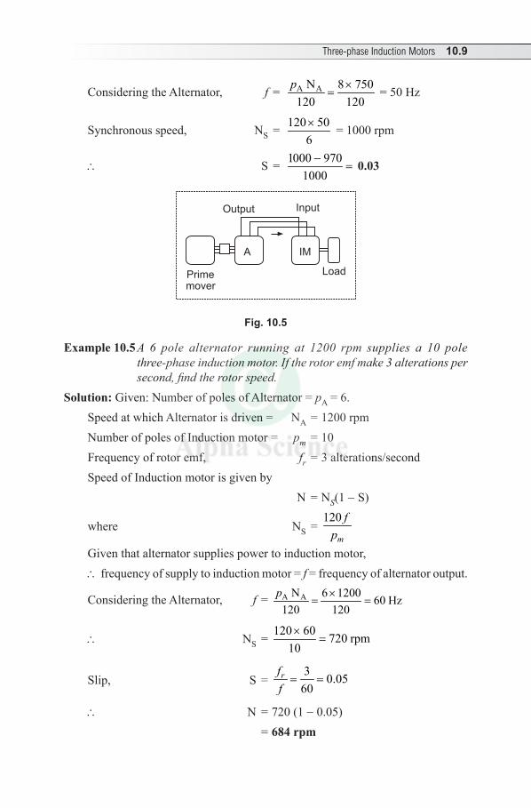
Three-phase Induction Motors 10.9
Considering the Alternator, f = A AN 8 750120 120
p ×= = 50 Hz
Synchronous speed, NS = 120 506× = 1000 rpm
\ S = 1000 970 0.031000-
= 0.03
moverPrime
InputOutput
A IM
Load
Fig. 10.5
Example 10.5 A 6 pole alternator running at 1200 rpm supplies a 10 pole three-phase induction motor. If the rotor emf make 3 alterations per second, find the rotor speed.
Solution: Given: Number of poles of Alternator = pA = 6.Speed at which Alternator is driven = NA = 1200 rpmNumber of poles of Induction motor = pm = 10Frequency of rotor emf, fr = 3 alterations/secondSpeed of Induction motor is given by N = N S(1 -S)
where NS = 120
m
fp
Given that alternator supplies power to induction motor,\ frequency of supply to induction motor = f = frequency of alternator output.
Considering the Alternator, f = A AN 6 1200 60 Hz120 120
p ×= =
\ NS = 120 60 720 rpm
10×
=
Slip, S = 3 0.05
60rff= =
\ N = 720 (1 -0.05) = 684 rpm
10.10 Electrical Engineering
Example 10.6 The power input to a 2000 V, 50 Hz, three-phase motor running on full-load at an efficiency of 90% is measured by two Wattmeters which indicate 300 kW and 100 kW respectively. Calculate (i) the input, (ii) the pf, (iii) the line current and (iv) HP Output.
Solution: Given: Input voltage = VL = 2000 volt, f = 50 Hz
Efficiency, h = 90% = 0.9
W1 = 300 kW and W2 = 100 kW
(i) Input, P = W1 + W2
= 300 + 100 = 400 kW
(ii) Power factor, pf = cos f
where f = tan–1 ( )1 2
1 2
3 W – WW + W
= tan–1 ( )3 300 – 10
300 + 100 = tan–1 (0.866) = 40.890
\ pf = cos (40.89°) = 0.755
(iii) Line current,
IL = 3 V cosL
pf
(Because P = 3 VL IL cos f)
= 400 1000 152.94 A
3 2000 0.755×
=× ×
= 152.9 A
(iv) Output in kW, P = Input in kW × h = 400 × 0.9 = 360 kW
\ Output in HP = 360 1000735.5×
= 489.46 HP
Advantages of induction motors:
1. Simple in construction,
2. Reliable,
3. Efficient,
4. Less maintenance and
5. Low cost.
Disadvantages of induction motors:
1. Difficult to achieve speed variation (in dc motor, speed variation is very easy)
2. Speed reduces with increase in load to some extent,
Three-phase Induction Motors 10.11
3. Less starting torque (as compared to dc motor) and4. As it is an induction machine, it operates at lagging power factor.Comparison between three-phase induction motor and transformerSimilarities:1. The stator and rotor of three-phase induction motor is similar to primary and
secondary of transformer respectively, because electrical power is transformed from stator to rotor by induction. Hence it is called as induction motor.
2. When the stator is energized by three-phase supply and the rotor is yet stationary, induction motor exactly resembles a transformer with its secondary short circuited.
Differences:As the three-phase induction motor is a rotating machine, the nature of load applied is mechanical whereas the transformer is a static device, its secondary is electrically loaded.
10.6 NECESSITY OF STARTER
At the time of starting, if an induction motor is directly connected to the supply, it draws excessive initial current (about 5 to 7 times) the full load current and produces only 1.5 to 2.5 times the full-load torque. This large starting current is objectionable as it causes large line drop and affects the operation of other interconnected apparatus. Hence starter is must for an induction motor.Types: • DOL starter • Star-delta Starter• Autotransformer Starter
10.7 STAR-DELTA STARTERConstruction
It consists of a changeover switch, which is in the form of double-throw type (with interlocks to prevent motor starting with the switch in the RUN position)
It connects the stator winding in Star at the instant of Starting and Delta for normal running. It is also provided with an Over load relay, protection against low voltage and Stop button switch for manual operation.
Working
At the instant of starting, the changeover switch is thrown to Star. For Star connection, applied voltage is given by
VL = 3 Vph
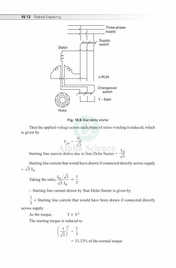
10.12 Electrical Engineering
Three-phasesupply
Supplyswitch
Stator
-RUN
Changeoverswitch
Y - Start
Rotor
Fig. 10.6 Star-delta starter
Then the applied voltage across each phase of stator winding is reduced, which is given by
Vph = V
3L
Starting line current drawn due to Star-Delta Starter = ISt
3
Starting line current that would have drawn if connected directly across supply = 3 ISt
Taking the ratio; I I
S
S
t
t
33
= 13
\Starting line current drawn by Star-Delta Starter is given by13
× Starting line current that would have been drawn if connected directly
across supplyAs the torque, T ∝ V2 The starting torque is reduced to
13
2
=
13
= 33.33% of the normal torque
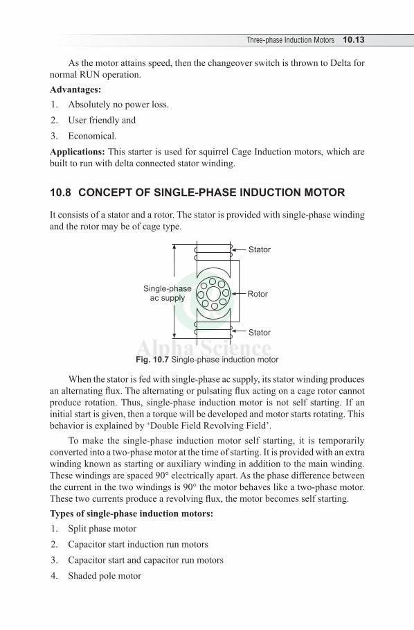
Three-phase Induction Motors 10.13
As the motor attains speed, then the changeover switch is thrown to Delta for normal RUN operation.Advantages:1. Absolutely no power loss.2. User friendly and3. Economical.Applications: This starter is used for squirrel Cage Induction motors, which are built to run with delta connected stator winding.
10.8 CONCEPT OF SINGLE-PHASE INDUCTION MOTOR
It consists of a stator and a rotor. The stator is provided with single-phase winding and the rotor may be of cage type.
Rotor
Stator
Stator
Single-phaseac supply
Fig. 10.7 Single-phase induction motor
When the stator is fed with single-phase ac supply, its stator winding produces an alternating flux. The alternating or pulsating flux acting on a cage rotor cannot produce rotation. Thus, single-phase induction motor is not self starting. If an initial start is given, then a torque will be developed and motor starts rotating. This behavior is explained by ‘Double Field Revolving Field’.
To make the single-phase induction motor self starting, it is temporarily converted into a two-phase motor at the time of starting. It is provided with an extra winding known as starting or auxiliary winding in addition to the main winding. These windings are spaced 90° electrically apart. As the phase difference between the current in the two windings is 90° the motor behaves like a two-phase motor. These two currents produce a revolving flux, the motor becomes self starting.Types of single-phase induction motors:1. Split phase motor2. Capacitor start induction run motors3. Capacitor start and capacitor run motors4. Shaded pole motor

10.14 Electrical Engineering
Types of single-phase ac motors: 1. Repulsion motor 2. AC Series motor 3. Unexcited synchronous motor
(a) Reluctance motor and (b) Hysterisis motor
Universal Motor: By special design, fractional hp series motor, which operates satisfactorily either on 50 Hz ac supply or dc supply and hence called the universal motor. It operates at approximately same speed and output on either ac or dc supply. It consists of two salient poles. The entire magnetic path is laminated as it operates on ac. The armature is wound type having laminated core, commutator and brushes.
Multiple Choice Questions
Choose the Correct Answer
1. An induction motor works with ......... (a) dc only (b) ac only(c) Both ac and dc only (d) none of these
2. When a three-phase supply is given to the stator of a three-phase induction motor, a ......magnetic field is produced. (a) stationary (b) alternating (c) rotating (d) none of these
3. The air-gap between the stator and rotor of a three-phase induction motor ranges from(a) 0.4 mm to 4 mm (b) 1 cm to 2 cm(c) 2 cm to 4 cm (d) 4 cm to 6 cm
4. If fm is the maximum value of flux due to any one of the three-phases in an induction motor, the resultant flux fr at any instant is
(a) 52fm (b) 3
2fm
(c) 23fm (d) 1
2fm
5. The rotor of an induction motor revolves in .......... direction of stator flux. (a) same (b) opposite(c) not determinable (d) none of these
Three-phase Induction Motors 10.15
6. If two of the supply lines of a three-phase induction motor are reversed, then .........(a) the speed increases(b) the speed decreases (c) the direction of rotation is reversed(d) motor stops
7. The rotor of a three-phase induction motor rotates in the same direction as that of stator rotating field. This can be explained by(a) Faraday’s Laws of EMI (b) Lenz’s Law (c) Newton’s Law of motion (d) Fleming’s Right-hand rule
8. The frame of induction motor is usually made of ...... (a) Silicon steel (b) Cast iron(c) Aluminium (d) Bronze
9. If the rotor terminals of a three-phase slip ring induction motor are not short-circuited and supply is given to the stator, the motor will(a) not start (b) start running(c) run at high speed (d) run at low speed
10. Compared to a slip ring induction motor, the starting torque of a squirrel cage induction motor is(a) same (b) high(c) very high (d) medium
11. Phase wound induction motors are less extensively used than squirrel cage induction motor because, (a) slip rings are required on the rotor circuit (b) rotor windings are generally star connected (c) they are costly and require greater maintenance (d) none of these
12. External resistance is connected to the rotor of a three-phase wound induction motor in order to (a) reduce starting current(b) collector current (c) to connect as a star connected load(d) none of these
13. The number of poles in a three-phase induction motor is determined by ........(a) supply frequency (b) motor speed(c) supply voltage (d) both (a) and (b)
10.16 Electrical Engineering
14. In a three-phase induction motor, the slip speed is given by .....(a) NS (b) N(c) NS – N (d) N – NS
15. Slip of an induction motor at standstill is .....(a) zero (b) one(c) infinity (d) none of these
16. Slip of an induction motor at standstill is .....(a) zero (b) unity(c) greater than unity (d) negative
17. When the rotor of a three-phase induction motor is blocked, the slip is .....(a) zero (b) 0.5(c) 0.1 (d) 1
18. The rotor of three-phase induction motor always runs at (a) synchronous speed (b) less than synchronous speed (c) more than synchronous speed (d) none of these
19. Synchronous speed of three-phase induction motor is given by(a) NS = 120 f P (b) NS = 120 f /P(c) NS = 120 P/f (d) NS = f P/120
20. The frequency of rotor current or emf is given by(a) f2 = sf1 (b) f2 = 000f1/s(c) f2 = (1 – S) f1 (d) f2 = s/f1
21. The difference between synchronous speed and actual speed is 100 rpm and synchronous speed is 1500 rpm, then the value of slip is(a) 2% (b) 10%(c) 6.66% (d) 15%
22. A supply of 50 Hz is given to a three-phase IM having 4 poles. If the IM runs at 1440 rpm, the slip is .....(a) 3% (b) 4%(c) 5% (d) 3.33%
23. An induction motor under full-load has a slip of about .......(a) 0.03 (b) 0.1(c) 0.3 (d) zero
24. Normal speed of a three-phase, 400 V, 50 Hz induction motor can be .......(a) 1455 rpm (b) 1550 rpm (c) 1500 rpm (d) 1050 rpm
Three-phase Induction Motors 10.17
25. A 4 pole, 50 Hz induction motor runs at a speed of 1440 rpm. The frequency of the rotor induced emf is ....... (a) 3 Hz (b) 2.5 Hz(c) 2 Hz (d) 4 Hz
26. If a 4 pole induction motor has a synchronous speed of 1500 rpm, the frequency of supply to the stator is (a) 25 Hz (b) 50 Hz(c) 100 Hz (d) 12.5 Hz
27. Induction motor works at (a) lagging pf (b) leading pf(c) upf (d) zero pf
28. In large induction motors starter is necessary because(a) stating torque is very high(b) motor takes 5-7 times its full-load current(c) it runs at dangerously high speed(d) it may run in reverse direction
Answers:—
1. (b) 2. (c) 3. (a) 4. (b) 5. (a) 6. (c) 7. (b) 8. (b) 9. (a) 10. (d)
11. (c) 12. (a) 13. (d) 14. (c) 15. (b) 16. (b) 17. (d) 18. (b) 19. (b) 20. (a)
21. (c) 22. (b) 23. (a) 24. (a) 25. (c) 26. (b) 27. (a) 28. (b)
Review Questions
1. What do you mean by rotating magnetic field? Explain the production of torque in a three-phase induction motor.
2. Explain the constructional features of induction motor. 3. Explain the principle of operation of a three-phase induction motor and give
reasons for ‘an induction motor can not run at synchronous speed’.4. Define slip. Derive an expression for frequency of rotor emf. 5. What is slip in an induction motor? Why slip is never zero in an induction
motor?6. Why three-phase induction motors are called asynchronous motors? Explain
the principle of operation of three-phase induction motor.
10.18 Electrical Engineering
7. With the help of neat figures of stator and rotors, explain construction of a squirrel cage and slip ring induction motor.
8. What are the advantages and disadvantages of three-phase induction motor?9. Discuss the application of Squirrel cage and Slip ring induction motor.10. Bring out the comparison between three-phase induction motor and transformer.11. Why are starters necessary for an induction motor? With a neat diagram explain
a star delta starter for a three-phase induction motor.
Exercises
1. A three-phase, 4-pole, 440 V and 50 Hz induction motor runs with a slip of 4%. Find the rotor speed and frequency of induced emf.
(Ans: N =1440 rpm and fr = 2 Hz)2. A three-phase, 6 pole, 60 Hz induction motor has a slip of 3% at full-load.
Find the synchronous speed and frequency of rotor current at full-load. (Ans: NS = 1200 rpm, fr = 1.8 Hz)3. The frequency of the emf in the stator of a 4-pole induction motor is 50 Hz
and in the rotor is 112
Hz. What is the slip and at what speed is the motor running? (Ans: S = 3%, N = 1455 rpm)
4. A 6 pole alternator is driven at 1200 rpm; (i) What is the frequency of the generated emf? (ii) If this alternator supplies power to a 10 pole induction motor, find its speed when slip is 3%. (Ans: f = 60 Hz, N = 698 rpm)
5. A three-phase induction motor has 6 poles and runs at 960 rpm on full-load. It is supplied from an alternator having 4 poles and running at 1500 rpm. Calculate the full-load slip of the motor. (Ans: S = 4%)
6. If the electromagnetic force in the stator of an 8-pole induction motor has a frequency of 50 Hz and that in rotor 1.5 Hz, at what speed is the motor running and what is the slip? (Ans: N = 728 rpm and S = 3%)
7. A 10 pole induction motor is supplied by a 6-pole alternator, which is driven at 1200 rpm If the motor runs with a slip of 3%, what is its speed?
(Ans: N = 698 rpm)
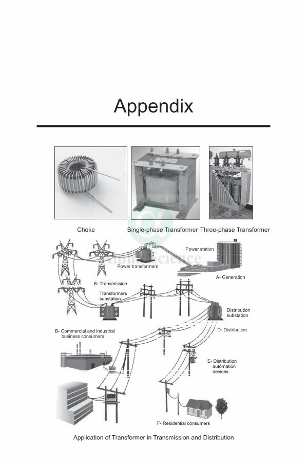
Choke Single-phase Transformer Three-phase Transformer
Power station
Power transformers
A- Generation
B- Transmission
Transformerssubstation
Distributionsubstation
B- Commercial and industrialbusiness consumers
D- Distribution
E- Distributionautomationdevices
F- Residential consumers
Application of Transformer in Transmission and Distribution
Appendix
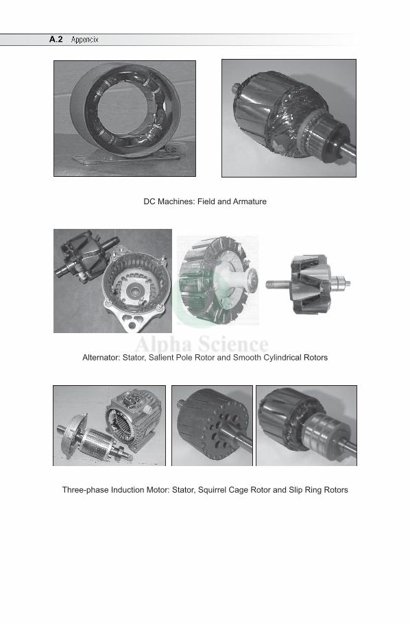
A.2 Appendix
DC Machines: Field and Armature
Alternator: Stator, Salient Pole Rotor and Smooth Cylindrical Rotors
Three-phase Induction Motor: Stator, Squirrel Cage Rotor and Slip Ring Rotors
A
Absolute Instruments 5.1Advantages of Stationary Armature 9.1Alternating Quantity 3.4Ampere 1.2Apparent Power 3.24Armature 7.2Armature Torque or Total Torque 7.29Average Value 3.7
B
Back emf and its Significance 7.20Balanced Load 4.3Balanced Supply 4.3Berry of Spiral Type Transformer 8.3Branch 1.25Branch Current Method 1.27
C
Calculation of Eg in Terms of Terminal Voltage 7.8, 7.10
Capacitive Circuit 3.27Capacitive Reactance 3.19Circuit Element 1.1Circuit with Capacitance (C) Only 3.18Circuit with Inductance (L) Only 3.16Circuit with Resistance (R) Only 3.14
Index
Circuits, Comparison between Magnetic and Electric 24
Cleat Wiring 6.2Coefficient of Magnetic Coupling (K)
2.16Coefficient of Mutual Inductance 2.13Coefficient of Self-Inductance 2.10Coil-Span or Coil-Pitch 9.5Comparison between dc Generator and
Alternator 9.1Comparison between dc Generator and dc
Motor 7.24Comparison between Magnetic and
Electric Circuits 2.24Comparison between Series and Parallel
Circuits 1.9Comparison between Three-Phase
Induction Motor and Transformer 10.11Complex Form 3.47Compound Generator 7.9Concept of Armature Reaction 7.19Concept of Autotransformer 8.22Concept of Rotating Magnetic Field 10.1Concept of Single-Phase Induction Motor
10.13Concept of Winding Factors 9.5Condition for Maximum Efficiency 8.13Condition for Maximum Power Developed
7.21Conduit Wiring 6.5Controlling or Restoring Torque 5.1
I.2 Index
Copper Loss (Wc) 8.12Core Type Transformer 8.2CTS or TRS Wiring 6.4Cumulative Compound 7.9Current 1.2Current Divider 1.7Cycle 3.4
D
Damping Torque 5.2DC Circuit 1.2DC Generator 7.1DC Motor 7.19DC Series Motor 7.23DC Shunt Motor 7.22Deflecting or Operating Torque 5.1Delta (D) or Mesh Connection 4.5Determination of Power Factor Using two
Wattmeters 4.15Differential Compound 7.10Distribution Board 6.1Distribution Factor 9.6Distribution Factor (Kd) 9.6Dynamically Induced emf 2.8Dynamometer Type Wattmeter 5.2
E
Earthing or Grounding 6.12Eddy Current Loss 8.11Effect of Temperature on Resistance 1.3Efficiency 8.12Electric Circuit 1.1Electric Shock 6.12Electrical 3.39Electrical Energy 1.10Electrical Load 1.8Electrical Power 1.10Electrical Resonance 3.39
Electromagnetic Induction 2.3Electromagnetism 2.1Electromotive Force 1.2Electromotive Force or Voltage 1.2Energy Stored in a Magnetic Field 2.18Equation for Flux (Ohm’s Law of
Magnetic Circuit) 2.3Equation of Alternating emf and Current
3.2
F
Faraday’s Laws of Electromagnetic Induction 2.4
Field System 7.1Fleming’s Left-Hand Rule 2.6Fleming’s Right-Hand Rule 2.5Force on a Current Carrying Conductor
Placed in a Magnetic Field 2.6Form Factor of a Sine Wave 3.10Frequency 3.4Frequency of Rotor emf or Rotor Current
Under Running Condition 10.6Full-Pitch 9.5Fuse 6.10Fuse Element Material 6.11
G
Generation of Three-Phase Voltage 4.1
H
Hysteresis Loss 8.11
I
Ideal Transformer 8.5Impedance 3.23, 27, 38Indicating Instrument 5.1Inductances Connected in Series 2.15Inductive Circuit 3.23, 39Inductive Reactance 3.17
Index I.3
Instantaneous Value 3.4Integrating Instrument 5.1Iron or Core Loss 8.11
J
Junction 1.25
K
Kirchhoff’s Current Law (KCL) 1.25Kirchhoff’s Voltage Law (KVL) 1.26
L
Lap Winding 7.5Lenz’s Law 2.5Long Shunt Compound Generator 7.10Loop 1.25Loop or Mesh Current Method 1.38
M
Magnetic Field 2.2Magnetic Flux 2.2Magnetic Flux Density 2.2Magnetizing Force 2.2Maxwell’s Loop Current 1.38Mcb 6.11Measurement of Current and Voltage 1.9Measurement of Reactive Power Using
two Wattmeters 4.16Measurement of Three-Phase Power Using
two Wattmeters 4.13Mesh 1.25Metal Sheathed Wiring 6.5Motor Characteristics and Applications
7.38Mutual Inductance 2.12
N
Necessity of Starter 10.11
Necessity of Starter 7.44Non-Salient Pole or Smooth Cylindrical
Rotor 9.3
O
Ohm 1.3Ohm’s Law 1.4
P
Peak or Crest or Amplitude Factor 3.10Peak Value or Amplitude or Maximum
Value 3.4Period or Time Period or Periodic Time
3.4Permeability 2.2Phase 3.13Phase Difference 3.13Phase-Sequence 4.2Pipe Earthing 6.13Pitch of a Winding 9.5Plate Earthing 6.14Polar to Rectangular Form 3.49Pole-Pitch 9.5Potential Difference 1.2Power Factor 3.25Power in Balanced Three-Phase Circuits
4.7Power Triangle 3.25Precautions Against Shock 6.12
R
Rating of a Transformer 8.12R-C Parallel Circuit 3.43R-C Series Circuit 3.26Reactive Power 3.24Real Power 3.24Recording Instrument 5.1Rectangular to Polar Form 3.49Relationship between Line and Phase
Values 4.6
I.4 Index
Relationship between Speed and Frequency 9.4
Relative Permeability 2.2Representation of Impedance (Z) as a
Complex Number 3.49Resistance 1.3Resistances Connected in Parallel 1.6Resistances Connected in Series 1.4R-L Parallel Circuit 3.42R-L Series Circuit 3.22R-L-C Series Circuit 3.37Rms Value 3.8Rotor 10.2Rotor-Rotating Field 9.2
S
Salient Pole or Projecting Pole Rotor 9.3Secondary Instruments 5.1Self- Inductance 2.10Self-Excited Generator 7.7Separately Excited Generator 7.7Series and Parallel Connection of Voltage
Sources 1.8Series Generator 7.9Shaft Torque 7.30Shell Type Transformer 8.2Short Shunt Compound Generator 7.11Short-Pitch or Fractional-Pitch Winding
9.6Shunt Generator 7.8Sign Convention 1.27Significance of Operator J 3.49Single-Phase Energy Meter 5.4Sinusoidal emf 3.3Sinusoidal Voltage 3.1Slip 10.5Slip Ring Rotor 10.3Speed of dc Motor 7.23Squirrel Cage Rotor 10.2Stair Case Lighting 6.8
Star (Y) Connection 4.3Star-Delta Starter 10.11Statically Induced emf 2.10Stator 10.2Stator or Stationary Armature 9.2Synchronous Generator 9.1Synchronous Speed 9.5
T
Three-Point Starter 7.45Three-Way Control of Lamp 6.8Torque 7.28Transformer 8.1Transformer on Load 8.15Transformer on No-Load 8.15Two-Way Control of Lamp 6.7Types of Single-Phase ac Motors 10.14Types of Single-Phase Induction Motors
10.13
U
Universal Motor 10.14
V
Volt 1.2Voltage Divider 1.5Voltage Regulation 8.16Voltage Regulation 9.11Voltage Transformation Ratio (K) 8.4
W
Wave Winding 7.5Waveform 3.3Wood Casing and Capping Wiring 6.3Working of a dc Machine as a dc
Generator 7.4Working Principal as a Motor 7.19Working Principle as a Generator 7.1