: basic electrical engineering - wordpress.com
TRANSCRIPT
Course Name : BASIC ELECTRICAL ENGINEERING
Course Code : A30202
Class : II B. Tech I Semester
Branch : Computer Science and Engineering
Year : 2016 – 2017
Course Faculty : Ms. Lekha Chandran, Associate professor
Mr. K.Lingaswamy Reddy, Assistant professor
OBJECTIVES
To meet the challenge of ensuring excellence in engineering education, the issue of quality needs to be addressed,
debated and taken forward in a systematic manner. Accreditation is the principal means of quality assurance in
higher education. The major emphasis of accreditation process is to measure the outcomes of the program that is
being accredited.
In line with this, Faculty of Institute of Aeronautical Engineering, Hyderabad has taken a lead in incorporating
philosophy of outcome based education in the process of problem solving and career development. So, all students
of the institute should understand the depth and approach of course to be taught through this question bank, which
will enhance learner’s learning process.
S. No Question Blooms
Taxonomy
Level
Course
Outcome
UNIT -1
INTRODUCTION TO ELECTRICAL ENGINEERING AND NETWORK ANALYSIS
Part - A (SHORT ANSWER QUESTIONS)
1 State Kirchhoff’s voltage law and Kirchhoff’s Current law? Remember 2
2 Explain ideal voltage and current source? Understand 1
3 Discuss the applications of both series and parallel combination? Understand 2
4 Discuss resistor, capacitor, and inductor with relevant expression? Understand 2
5 Explain the equations for resistors in equivalent delta. If the resistors Ra, Rb
and Rc are connected electrically in star?
Evaluate 2
6 State Ohm’s law? Evaluate 1
7 State Superposition Theorem? Remember 3
8 State Thevinins Theorem? Remember 3
9 State Maximum power transfer theorem? Remember 3
10 Explain difference between series and parallel resistive circuit? Understand 2
11 Explain the equations for resistors in equivalent star. If the resistors Ra, Rb
and Rc are connected electrically in delta?
Evaluate 2
S. No Question Blooms
Taxonomy
Level
Course
Outcome
12 Discuss limitations of ohm’s law? Understand 2
13 Define resistance and state its units. On which factors the resistance of a
material depends?
Remember 7
14 Define conductance and state its units Remember 7
15 Define electrical energy. state its units Remember 7
Part - B(LONG ASNWERS QUESTIONS)
1 Explain two capacitors are connected in series then Ceq=C1C2/C1+C2? Evaluate 1
2 Explain derivation of star-delta conversion equations? Evaluate 2
3 Explain derivation of delta-star conversion equations? Evaluate 2
4 Explain in detail the volt-ampere relationship of R, L and C elements with
neat diagrams? Understand 1
5 Explain about series and parallel networks of resistor? Understand 1
6 Explain about series and parallel networks of inductor? Understand 1
7 Explain classification of network elements? Understand 1
8 Explain superposition theorem? Remember 3
9 Explain Thevinin’s theorem? Remember 3
10 Derive the condition for maximum power transfer theorem? Evaluate 3
11 Write differences between ideal and practical voltage sources? Understand 2
12 Write differences between ideal and practical current sources? Understand 2
13 Write a notes on dependent sources? Understand 2
14 Write down KVL and KCL and explain? Understand 2
15 Write the characteristics of series and parallel circuits? Understand 2
Part - C (Problem Solving and Critical Thinking Questions)
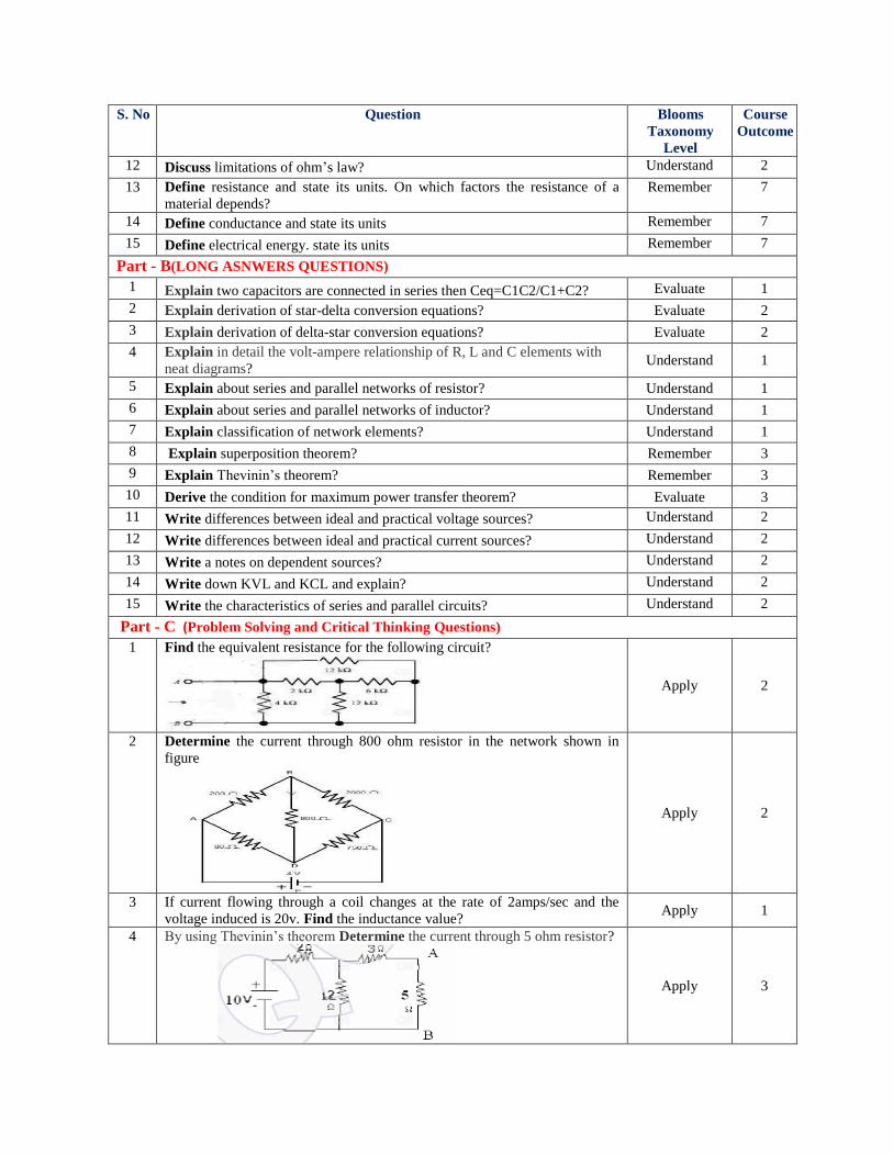
1 Find the equivalent resistance for the following circuit?
Apply 2
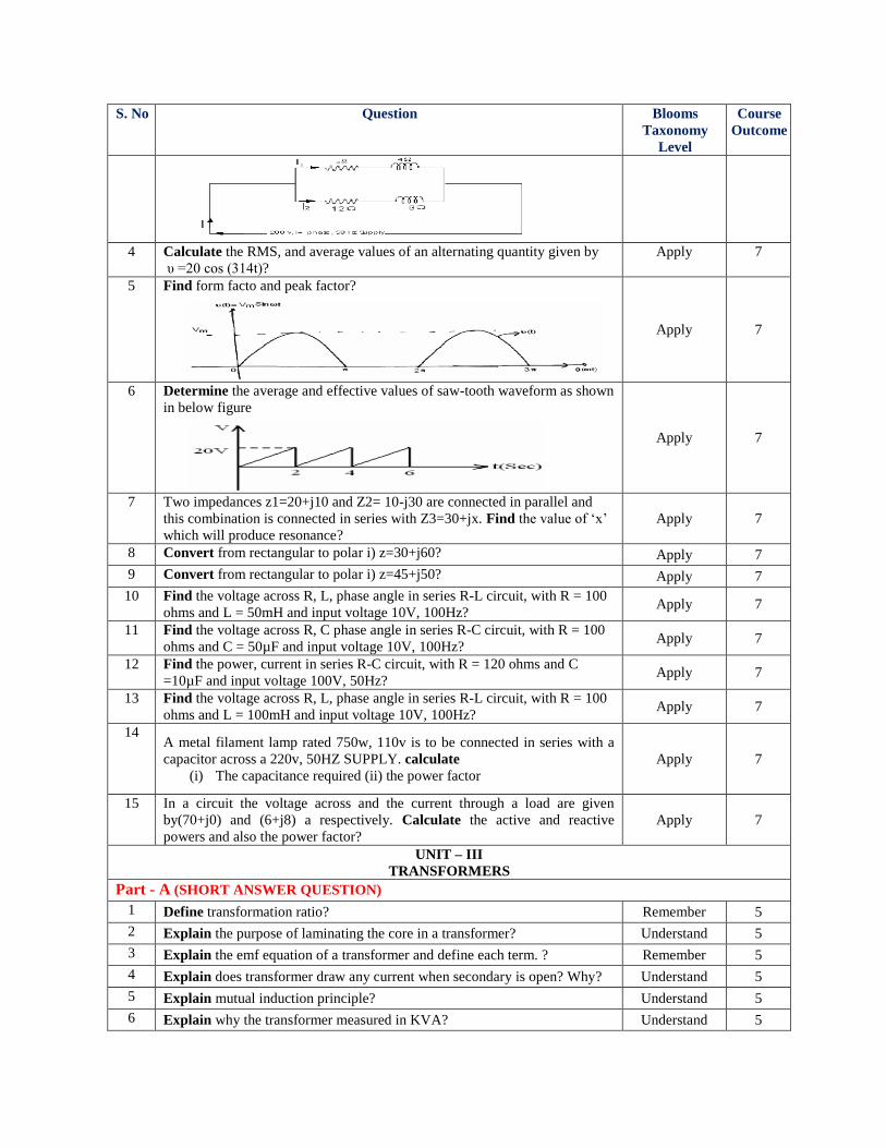
2 Determine the current through 800 ohm resistor in the network shown in
figure
Apply 2
3 If current flowing through a coil changes at the rate of 2amps/sec and the
voltage induced is 20v. Find the inductance value? Apply 1
4 By using Thevinin’s theorem Determine the current through 5 ohm resistor?
Apply 3
S. No Question Blooms
Taxonomy
Level
Course
Outcome
5
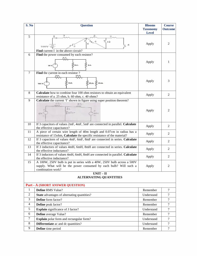
Find current I in the above circuit?
Apply 2
6 Find the power consumed by each resistor?
Apply 1
7 Find the current in each resistor ?
Apply 3
8 Calculate how to combine four 100 ohm resistors to obtain an equivalent
resistance of a. 25 ohm, b. 60 ohm, c. 40 ohms? Apply 2
9 Calculate the current ‘I’ shown in figure using super position theorem?
Apply 2
10 If 3 capacitors of values 2mF, 4mF, 5mF are connected in parallel. Calculate
the effective capacitance? Apply 2
11 A piece of certain wire length of 40m length and 0.07cm in radius has a
resistance of 15ohm, Calculate the specific resistance of the material? Apply 2
12 If 3 capacitors of values 4mF, 6mF, 8mF are connected in series. Calculate
the effective capacitance? Apply 2
13 If 3 inductors of values 4mH, 6mH, 8mH are connected in series. Calculate
the effective inductance? Apply 2
14 If 3 inductors of values 4mH, 6mH, 8mH are connected in parallel. Calculate
the effective inductance? Apply 2
15 A 100W, 250V bulb is put in series with a 40W, 250V bulb across a 500V
supply. What will be the power consumed by each bulb? Will such a
combination work?
Apply 2
UNIT – II
ALTERNATING QUANTITIES
Part - A (SHORT ANSWER QUESTION)
1 Define RMS Value? Remember 7
2 State advantages of alternating quantities? Understand 7
3 Define form factor? Remember 7
4 Define peak factor? Remember 7
5 Explain significance of J factor? Understand 7
6 Define average Value? Remember 7
7 Explain polar form and rectangular form? Understand 7
8 Differentiate ac and dc quantities? Understand 7
9 Define time period Remember 7
S. No Question Blooms
Taxonomy
Level
Course
Outcome
10 Define cycle Remember 7
11 Define frequency? Remember 7
12 Define waveform? Remember 7
13 Define peak value? Remember 7
14 Define instantaneous value? Remember 7
15 Discuss concept of phase and phase difference? Remember 7
Part – B (LONG ASNWERS QUESTIONS)
1 Explain following terms:
i) Impedance ii) admittance iii) susceptance iv) conductance
v)Power factor ?
Remember 7
2 Write about series RL circuit? Understand 7
3 Write about series RC circuit? Understand 7
4 Explain behavior of RLC Series circuit? Understand 7
5 Explain i) rectangular form ii) polar form ? Understand 7
6 Explain significance of J-Operator? Understand 7
7 Write equations for RMS value, average value, form factor and peak factor? Understand 7
8 Discuss what are the advantages of AC quantities? Understand 7
9 Explain conversion from rectangular form to polar form? Understand 7
10 Explain conversion from polar form to rectangular form? Understand 7
11 Explain the behavior of ac through resistance (R)derive instantaneous value
of v and i, average power ,power factor, instantaneous power,and relevant
phasors.
Understand 7
12 Explain how the voltage and current in purely resistive circuit are in phase Understand 7
13 Explain the behavior of ac through inductance (L).derive instantaneous value
of v and i, average power, power factor, instantaneous power,and relevant
phasors.
Understand 7
14 Explain the behavior of ac through capacitance(C).derive instantaneous
value of v and i, average power, power factor, instantaneous power,and
relevant phasors.
Understand 7
15
Explain admittance method to solve parallel circuit? Understand 7
Part - C (Problem Solving and Critical Thinking Questions)
1 A circuit consists of a resistance of 15ohm, a capacitance of 200 micro Farad
and inductor of 0.05H all in series. If supply of 230V, 50Hz is applied to the
ends of circuit. Calculate i) Current in the coil ii) Potential difference across
each element?
Apply 7
2 Write about series RC circuit? Understand 7
3 Solve the following parallel circuit and find out current in each branch and
total current as shown in figure
Apply 7
S. No Question Blooms
Taxonomy
Level
Course
Outcome
4 Calculate the RMS, and average values of an alternating quantity given by
υ =20 cos (314t)?
Apply 7
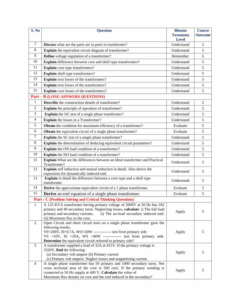
5 Find form facto and peak factor?
Apply 7
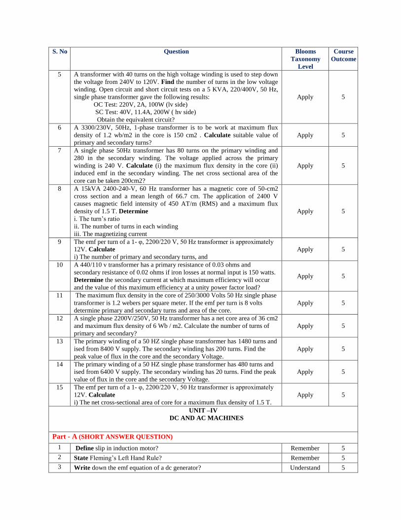
6 Determine the average and effective values of saw-tooth waveform as shown
in below figure
Apply 7
7 Two impedances z1=20+j10 and Z2= 10-j30 are connected in parallel and
this combination is connected in series with Z3=30+jx. Find the value of ‘x’
which will produce resonance?
Apply 7
8 Convert from rectangular to polar i) z=30+j60? Apply 7
9 Convert from rectangular to polar i) z=45+j50? Apply 7
10 Find the voltage across R, L, phase angle in series R-L circuit, with R = 100
ohms and L = 50mH and input voltage 10V, 100Hz? Apply 7
11 Find the voltage across R, C phase angle in series R-C circuit, with R = 100
ohms and C = 50µF and input voltage 10V, 100Hz? Apply 7
12 Find the power, current in series R-C circuit, with R = 120 ohms and C
=10µF and input voltage 100V, 50Hz? Apply 7
13 Find the voltage across R, L, phase angle in series R-L circuit, with R = 100
ohms and L = 100mH and input voltage 10V, 100Hz? Apply 7
14 A metal filament lamp rated 750w, 110v is to be connected in series with a
capacitor across a 220v, 50HZ SUPPLY. calculate
(i) The capacitance required (ii) the power factor
Apply 7
15 In a circuit the voltage across and the current through a load are given
by(70+j0) and (6+j8) a respectively. Calculate the active and reactive
powers and also the power factor?
Apply 7
UNIT – III
TRANSFORMERS
Part - A (SHORT ANSWER QUESTION)
1 Define transformation ratio? Remember 5
2 Explain the purpose of laminating the core in a transformer? Understand 5
3 Explain the emf equation of a transformer and define each term. ? Remember 5
4 Explain does transformer draw any current when secondary is open? Why? Understand 5
5 Explain mutual induction principle? Understand 5
6 Explain why the transformer measured in KVA? Understand 5
S. No Question Blooms
Taxonomy
Level
Course
Outcome
7 Discuss what are the parts are in parts in transformer? Understand 5
8 Explain the equivalent circuit diagram of transformer? Understand 5
9 Define voltage regulation of a transformer? Remember 5
10 Explain difference between core and shell type transformers? Understand 5
11 Explain core type transformers? Understand 5
12 Explain shell type transformers? Understand 5
13 Explain iron losses of the transformers? Understand 5
14 Explain iron losses of the transformers? Understand 5
15 Explain core losses of the transformers? Understand 5
Part – B (LONG ASNWERS QUESTIONS)
1 Describe the construction details of transformer? Understand 5
2 Explain the principle of operation of transformer? Understand 5
3 Explain the OC test of a single phase transformer? Understand 5
4 Explain the losses in a Transformer? Understand 5
5 Obtain the condition for maximum efficiency of a transformer? Evaluate 5
6 Obtain the equivalent circuit of a single phase transformer? Evaluate 5
7 Explain the SC test of a single phase transformer? Understand 5
8 Explain the determination of deducing equivalent circuit parameters? Understand 5
9 Explain the ON load condition of a transformer? Understand 5
10 Explain the NO load condition of a transformer? Understand 5
11 Explain What are the differences between an Ideal transformer and Practical
Transformer? Understand 5
12 Explain self induction and mutual induction in detail. Also derive the
expression for dynamically induced emf. Understand 5
13 Explain in detail the difference between a core type and a shell type
transformer. Understand 5
14 Derive the approximate equivalent circuit of a 1 phase transformer. Evaluate 5
15 Derive an emf equation of a single phase transformer. Evaluate 5
Part - C (Problem Solving and Critical Thinking Questions)
1 A 125 KVA transformer having primary voltage of 2000V at 50 Hz has 182
primary and 40 secondary turns. Neglecting losses, calculate: i) The full load
primary and secondary currents. ii) The no-load secondary induced emf.
iii) Maximum flux in the core.
Apply 5
2 Open Circuit and short circuit tests on a single phase transformer gave the
following results.
V0=200V, I0=0.7A, WO=20W -------------- test from primary side
VS =10V, IS =10A, WS =40W -------------- test from primary side.
Determine the equivalent circuit referred to primary side?
Apply 5
3 A transformer supplied a load of 32A at 415V. If the primary voltage is
3320V, find the following:
(a) Secondary volt ampere (b) Primary current
(c) Primary volt ampere. Neglect losses and magnetizing current.
Apply 5
4 A single phase transformer has 50 primary and 1000 secondary turns. Net
cross sectional area of the core is 500 cm2. If the primary winding is
connected to 50 Hz supply at 400 V, Calculate the value of
Maximum flux density on core and the emf induced in the secondary?
Apply 5
S. No Question Blooms
Taxonomy
Level
Course
Outcome
5 A transformer with 40 turns on the high voltage winding is used to step down
the voltage from 240V to 120V. Find the number of turns in the low voltage
winding. Open circuit and short circuit tests on a 5 KVA, 220/400V, 50 Hz,
single phase transformer gave the following results:
OC Test: 220V, 2A, 100W (lv side)
SC Test: 40V, 11.4A, 200W ( hv side)
Obtain the equivalent circuit?
Apply 5
6 A 3300/230V, 50Hz, 1-phase transformer is to be work at maximum flux
density of 1.2 wb/m2 in the core is 150 cm2 . Calculate suitable value of
primary and secondary turns?
Apply 5
7 A single phase 50Hz transformer has 80 turns on the primary winding and
280 in the secondary winding. The voltage applied across the primary
winding is 240 V. Calculate (i) the maximum flux density in the core (ii)
induced emf in the secondary winding. The net cross sectional area of the
core can be taken 200cm2?
Apply 5
8 A 15kVA 2400-240-V, 60 Hz transformer has a magnetic core of 50-cm2
cross section and a mean length of 66.7 cm. The application of 2400 V
causes magnetic field intensity of 450 AT/m (RMS) and a maximum flux
density of 1.5 T. Determine
i. The turn’s ratio
ii. The number of turns in each winding
iii. The magnetizing current
Apply 5
9 The emf per turn of a 1- φ, 2200/220 V, 50 Hz transformer is approximately
12V. Calculate
i) The number of primary and secondary turns, and
Apply 5
10 A 440/110 v transformer has a primary resistance of 0.03 ohms and
secondary resistance of 0.02 ohms if iron losses at normal input is 150 watts.
Determine the secondary current at which maximum efficiency will occur
and the value of this maximum efficiency at a unity power factor load?
Apply 5
11 The maximum flux density in the core of 250/3000 Volts 50 Hz single phase
transformer is 1.2 webers per square meter. If the emf per turn is 8 volts
determine primary and secondary turns and area of the core.
Apply 5
12 A single phase 2200V/250V, 50 Hz transformer has a net core area of 36 cm2
and maximum flux density of 6 Wb / m2. Calculate the number of turns of
primary and secondary?
Apply 5
13 The primary winding of a 50 HZ single phase transformer has 1480 turns and
ised from 8400 V supply. The secondary winding has 200 turns. Find the
peak value of flux in the core and the secondary Voltage.
Apply 5
14 The primary winding of a 50 HZ single phase transformer has 480 turns and
ised from 6400 V supply. The secondary winding has 20 turns. Find the peak
value of flux in the core and the secondary Voltage.
Apply 5
15 The emf per turn of a 1- φ, 2200/220 V, 50 Hz transformer is approximately
12V. Calculate
i) The net cross-sectional area of core for a maximum flux density of 1.5 T. Apply 5
UNIT –IV
DC AND AC MACHINES
Part - A (SHORT ANSWER QUESTION)
1 Define slip in induction motor? Remember 5
2 State Fleming’s Left Hand Rule? Remember 5
3 Write down the emf equation of a dc generator? Understand 5
S. No Question Blooms
Taxonomy
Level
Course
Outcome
4 Write down the torque equation of a D.C motor? Understand 5
5 State the function of brushes? Remember 5
6 State Fleming’s Right Hand Rule? Remember 6
7 Write expression for rotor current frequency? Understand 6
8 What is principle operation of 3-phase induction motor? Understand 6
9 Explain the slip-torque characteristics of 3-phase induction motor? Understand 6
10 State two types of induction motors? Understand 6
11 State Fleming’s right Hand Rule? Understand 6
12 What is principle operation of dc generator? Understand 6
13 State the function of commutator? Remember 6
14 State the function of slots? Remember 6
15 State the function of slip rings? Remember 6
Part – B (LONG ASNWERS QUESTIONS)
1 Explain the classification of DC generator? Understand 5
2 Derive the equation for induced EMF of a DC generator? Evaluate 5
3 Derive the torque equation of DC motor? Evaluate 5
4 Explain the principle and construction of a 3 phase induction motor? Understand 6
5 Derive the expression for rotor frequency? Evaluate 6
6 Explain why does an induction motor never runs at Synchronous speed? Understand 6
7 Obtain the condition for maximum running torque of an induction motor? Understand 6
8 Explain the classification of DC Motor and explain?
Understand 6
9 Explain the significance of back emf in a DC motor?
Understand 6
10 Explain the load characteristics of shunt, series and compound generators?
Understand 6
11 Explain the reasons for the following
i. A series motor should not be connected to a load through a belt
ii. A series motor develops a high starting torque
iii. A differential compound motor is very rarely used
iv. A shunt motor runs at almost constant speed irrespective of load current.
Understand 6
12 Explain How may the direction of rotation of dc shunt motor be reversed?
What is the effect of reversing the line terminals? Understand 6
13 Explain: i. Slip speed
ii. Slip
iii. Synchronous Speed
iv. Torque.
Understand 6
14 Explain Why an induction motor is called a rotating transformer? Justify Understand 6
15 Derive the expression for the armature torque and shaft torque of a DC motor Evaluate 5
Part – C (Problem Solving and Critical Thinking Questions)
1 Calculate the e.m.f by 4 pole wave wound generator having 65 slots with
12 conductors per slot when driven at 1200 rpm the flux per pole is 0.02 wb? Apply 5
2 A dynamo has a rated armature current at 250 amps what is the current per
path of the armature if the armature winding is lap or wave wound? The
machine has 12 poles.
Apply 5
S. No Question Blooms
Taxonomy
Level
Course
Outcome
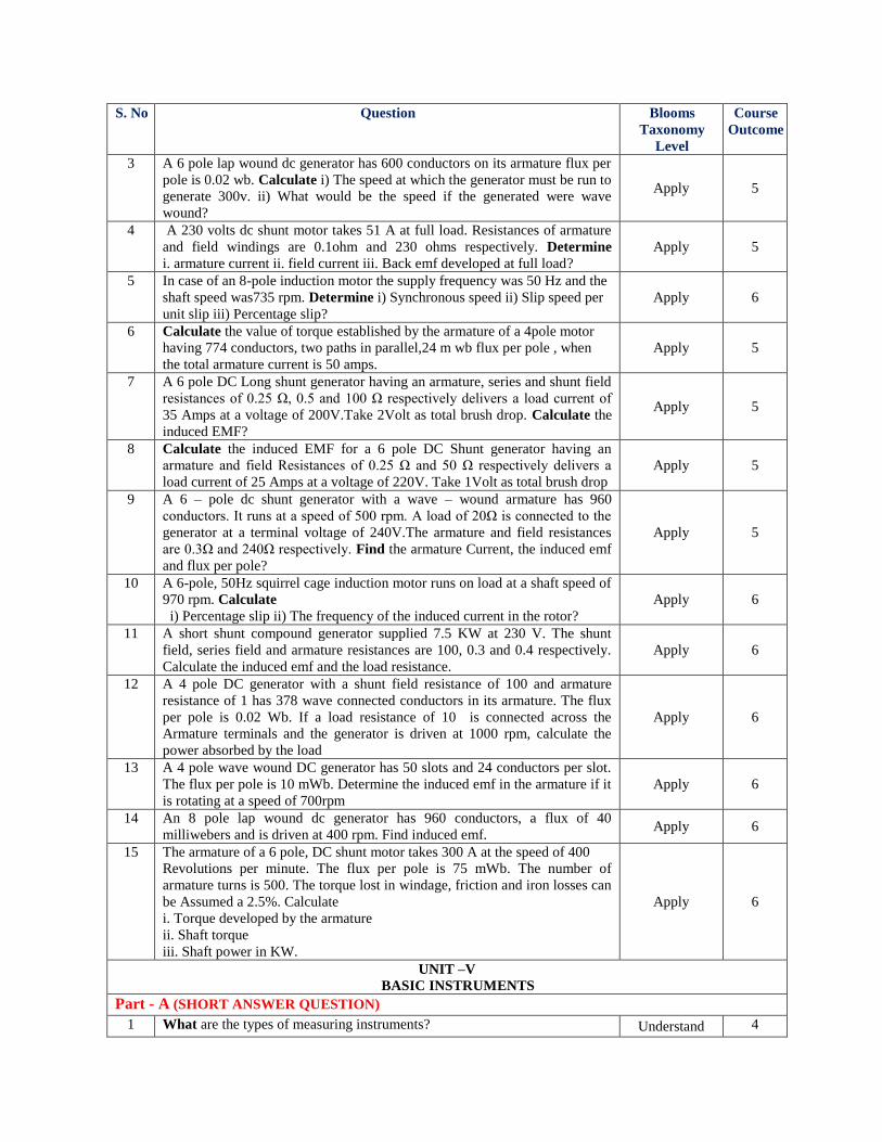
3 A 6 pole lap wound dc generator has 600 conductors on its armature flux per
pole is 0.02 wb. Calculate i) The speed at which the generator must be run to
generate 300v. ii) What would be the speed if the generated were wave
wound?
Apply 5
4 A 230 volts dc shunt motor takes 51 A at full load. Resistances of armature
and field windings are 0.1ohm and 230 ohms respectively. Determine
i. armature current ii. field current iii. Back emf developed at full load?
Apply 5
5 In case of an 8-pole induction motor the supply frequency was 50 Hz and the
shaft speed was735 rpm. Determine i) Synchronous speed ii) Slip speed per
unit slip iii) Percentage slip?
Apply 6
6 Calculate the value of torque established by the armature of a 4pole motor
having 774 conductors, two paths in parallel,24 m wb flux per pole , when
the total armature current is 50 amps.
Apply 5
7 A 6 pole DC Long shunt generator having an armature, series and shunt field
resistances of 0.25 Ω, 0.5 and 100 Ω respectively delivers a load current of
35 Amps at a voltage of 200V.Take 2Volt as total brush drop. Calculate the
induced EMF?
Apply 5
8 Calculate the induced EMF for a 6 pole DC Shunt generator having an
armature and field Resistances of 0.25 Ω and 50 Ω respectively delivers a
load current of 25 Amps at a voltage of 220V. Take 1Volt as total brush drop
Apply 5
9 A 6 – pole dc shunt generator with a wave – wound armature has 960
conductors. It runs at a speed of 500 rpm. A load of 20Ω is connected to the
generator at a terminal voltage of 240V.The armature and field resistances
are 0.3Ω and 240Ω respectively. Find the armature Current, the induced emf
and flux per pole?
Apply 5
10 A 6-pole, 50Hz squirrel cage induction motor runs on load at a shaft speed of
970 rpm. Calculate
i) Percentage slip ii) The frequency of the induced current in the rotor?
Apply 6
11 A short shunt compound generator supplied 7.5 KW at 230 V. The shunt
field, series field and armature resistances are 100, 0.3 and 0.4 respectively.
Calculate the induced emf and the load resistance.
Apply 6
12 A 4 pole DC generator with a shunt field resistance of 100 and armature
resistance of 1 has 378 wave connected conductors in its armature. The flux
per pole is 0.02 Wb. If a load resistance of 10 is connected across the
Armature terminals and the generator is driven at 1000 rpm, calculate the
power absorbed by the load
Apply 6
13 A 4 pole wave wound DC generator has 50 slots and 24 conductors per slot.
The flux per pole is 10 mWb. Determine the induced emf in the armature if it
is rotating at a speed of 700rpm
Apply 6
14 An 8 pole lap wound dc generator has 960 conductors, a flux of 40
milliwebers and is driven at 400 rpm. Find induced emf. Apply 6
15 The armature of a 6 pole, DC shunt motor takes 300 A at the speed of 400
Revolutions per minute. The flux per pole is 75 mWb. The number of
armature turns is 500. The torque lost in windage, friction and iron losses can
be Assumed a 2.5%. Calculate
i. Torque developed by the armature
ii. Shaft torque
iii. Shaft power in KW.
Apply 6
UNIT –V
BASIC INSTRUMENTS
Part - A (SHORT ANSWER QUESTION)
1 What are the types of measuring instruments? Understand 4
S. No Question Blooms
Taxonomy
Level
Course
Outcome
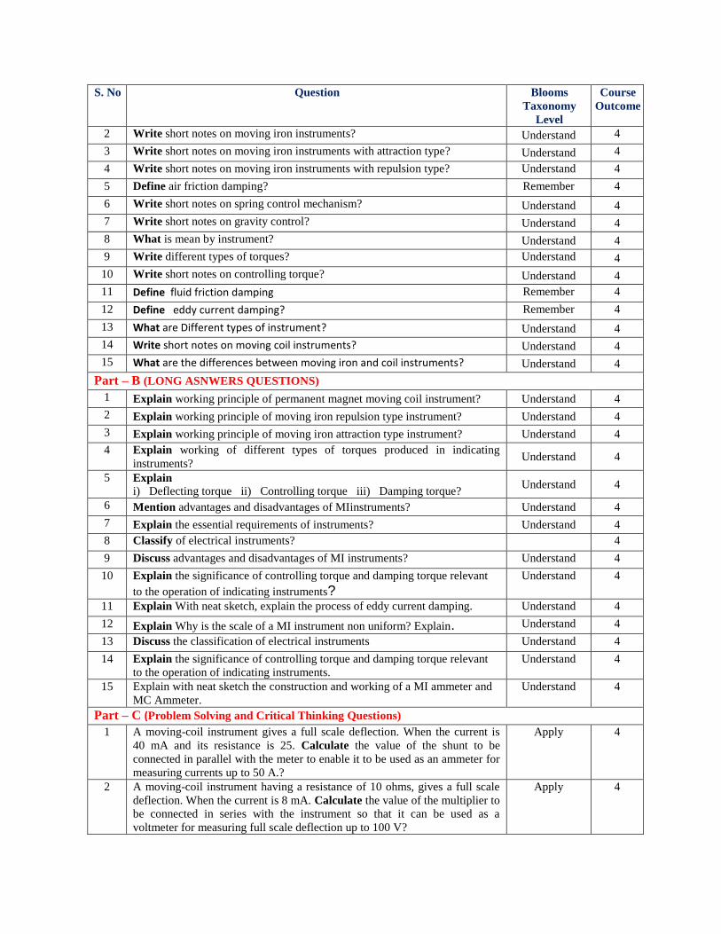
2 Write short notes on moving iron instruments? Understand 4
3 Write short notes on moving iron instruments with attraction type? Understand 4
4 Write short notes on moving iron instruments with repulsion type? Understand 4
5 Define air friction damping? Remember 4
6 Write short notes on spring control mechanism? Understand 4
7 Write short notes on gravity control? Understand 4
8 What is mean by instrument? Understand 4
9 Write different types of torques? Understand 4
10 Write short notes on controlling torque? Understand 4
11 Define fluid friction damping Remember 4
12 Define eddy current damping? Remember 4
13 What are Different types of instrument? Understand 4
14 Write short notes on moving coil instruments? Understand 4
15 What are the differences between moving iron and coil instruments? Understand 4
Part – B (LONG ASNWERS QUESTIONS)
1 Explain working principle of permanent magnet moving coil instrument? Understand 4
2 Explain working principle of moving iron repulsion type instrument? Understand 4
3 Explain working principle of moving iron attraction type instrument? Understand 4
4 Explain working of different types of torques produced in indicating
instruments? Understand 4
5 Explain
i) Deflecting torque ii) Controlling torque iii) Damping torque? Understand 4
6 Mention advantages and disadvantages of MIinstruments? Understand 4
7 Explain the essential requirements of instruments? Understand 4
8 Classify of electrical instruments? 4
9 Discuss advantages and disadvantages of MI instruments? Understand 4
10 Explain the significance of controlling torque and damping torque relevant
to the operation of indicating instruments? Understand 4
11 Explain With neat sketch, explain the process of eddy current damping. Understand 4
12 Explain Why is the scale of a MI instrument non uniform? Explain. Understand 4
13 Discuss the classification of electrical instruments Understand 4
14 Explain the significance of controlling torque and damping torque relevant
to the operation of indicating instruments.
Understand 4
15 Explain with neat sketch the construction and working of a MI ammeter and
MC Ammeter.
Understand 4
Part – C (Problem Solving and Critical Thinking Questions)
1 A moving-coil instrument gives a full scale deflection. When the current is
40 mA and its resistance is 25. Calculate the value of the shunt to be
connected in parallel with the meter to enable it to be used as an ammeter for
measuring currents up to 50 A.?
Apply 4
2 A moving-coil instrument having a resistance of 10 ohms, gives a full scale
deflection. When the current is 8 mA. Calculate the value of the multiplier to
be connected in series with the instrument so that it can be used as a
voltmeter for measuring full scale deflection up to 100 V?
Apply 4
S. No Question Blooms
Taxonomy
Level
Course
Outcome
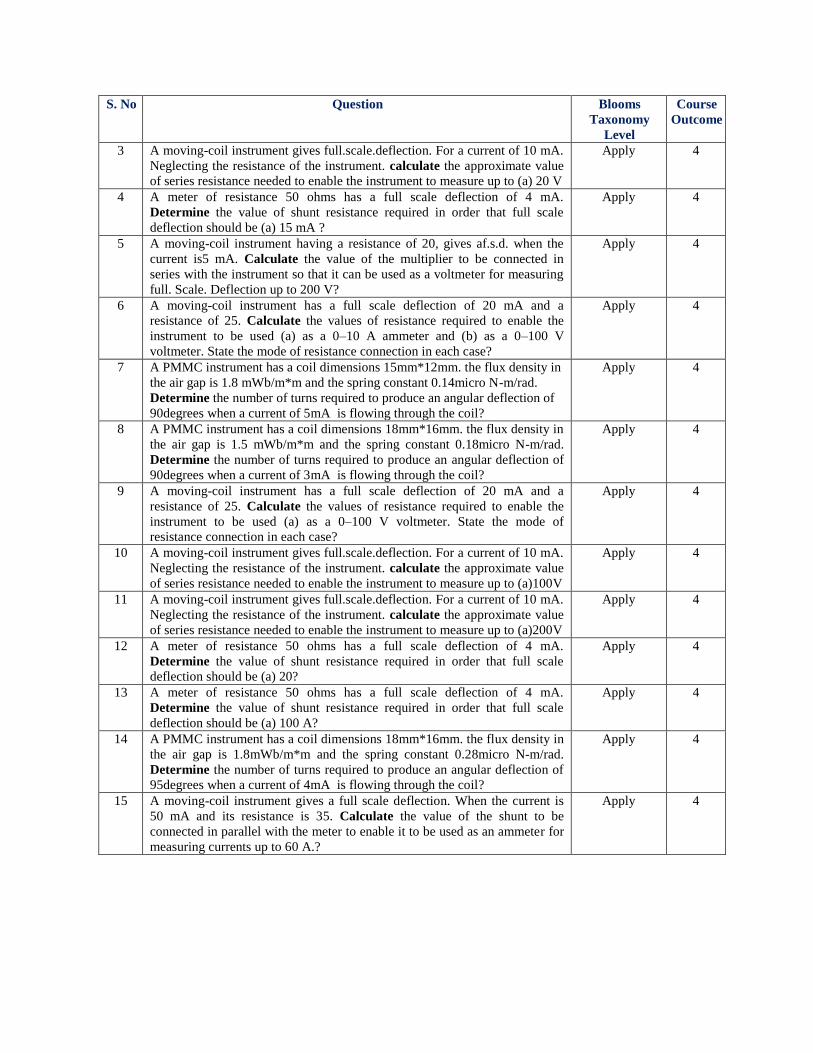
3 A moving-coil instrument gives full.scale.deflection. For a current of 10 mA.
Neglecting the resistance of the instrument. calculate the approximate value
of series resistance needed to enable the instrument to measure up to (a) 20 V
Apply 4
4 A meter of resistance 50 ohms has a full scale deflection of 4 mA.
Determine the value of shunt resistance required in order that full scale
deflection should be (a) 15 mA ?
Apply 4
5 A moving-coil instrument having a resistance of 20, gives af.s.d. when the
current is5 mA. Calculate the value of the multiplier to be connected in
series with the instrument so that it can be used as a voltmeter for measuring
full. Scale. Deflection up to 200 V?
Apply 4
6 A moving-coil instrument has a full scale deflection of 20 mA and a
resistance of 25. Calculate the values of resistance required to enable the
instrument to be used (a) as a 0–10 A ammeter and (b) as a 0–100 V
voltmeter. State the mode of resistance connection in each case?
Apply 4
7 A PMMC instrument has a coil dimensions 15mm*12mm. the flux density in
the air gap is 1.8 mWb/m*m and the spring constant 0.14micro N-m/rad.
Determine the number of turns required to produce an angular deflection of
90degrees when a current of 5mA is flowing through the coil?
Apply 4
8 A PMMC instrument has a coil dimensions 18mm*16mm. the flux density in
the air gap is 1.5 mWb/m*m and the spring constant 0.18micro N-m/rad.
Determine the number of turns required to produce an angular deflection of
90degrees when a current of 3mA is flowing through the coil?
Apply 4
9 A moving-coil instrument has a full scale deflection of 20 mA and a
resistance of 25. Calculate the values of resistance required to enable the
instrument to be used (a) as a 0–100 V voltmeter. State the mode of
resistance connection in each case?
Apply 4
10 A moving-coil instrument gives full.scale.deflection. For a current of 10 mA.
Neglecting the resistance of the instrument. calculate the approximate value
of series resistance needed to enable the instrument to measure up to (a)100V
Apply 4
11 A moving-coil instrument gives full.scale.deflection. For a current of 10 mA.
Neglecting the resistance of the instrument. calculate the approximate value
of series resistance needed to enable the instrument to measure up to (a)200V
Apply 4
12 A meter of resistance 50 ohms has a full scale deflection of 4 mA.
Determine the value of shunt resistance required in order that full scale
deflection should be (a) 20?
Apply 4
13 A meter of resistance 50 ohms has a full scale deflection of 4 mA.
Determine the value of shunt resistance required in order that full scale
deflection should be (a) 100 A?
Apply 4
14 A PMMC instrument has a coil dimensions 18mm*16mm. the flux density in
the air gap is 1.8mWb/m*m and the spring constant 0.28micro N-m/rad.
Determine the number of turns required to produce an angular deflection of
95degrees when a current of 4mA is flowing through the coil?
Apply 4
15 A moving-coil instrument gives a full scale deflection. When the current is
50 mA and its resistance is 35. Calculate the value of the shunt to be
connected in parallel with the meter to enable it to be used as an ammeter for
measuring currents up to 60 A.?
Apply 4
Prepared By: Ms. Lekha Chandran, Associate professor.
Mr. K. Lingaswamy Reddy, Assistant Professor
HOD, COMPUTER SCIENCE AND ENGINEERING