electrical engineering - vidyalankar.org
TRANSCRIPT

7
S.Y. Diploma : Sem. III Electrical Engineering
[EJ/EN/ET/EX/DE/IS/IC/IE/EV/MU] Time: 3 Hrs.] MSBTE Prelim Question Paper Solution [Marks : 100
Q.1 Attempt any TEN of the following. [20]Q.1 (a) State E.M.F. equation of transformer and write meaning of each term
in the formula. [2]
(A) E.M. F. equation of transformer: E1 = 4.44 fmax N1 OR E1 = 4.44 Bmax N1 E2 = 4.44 fmax N2 OR E2 = 4.44 Bmax N2 where N1 = number of turns in primary N2 = number of turns in secondary max = maximum flux in core in weber Bmax = maximum flux density in core in Wb/m2 A = core area in (meter)2 E1 = R.M.S. value of induced emf in primary E2 = R.M.S. value of induced emf in secondary Q.1 (b) Why should a transformer be never connected to DC supply. [2](A) With DC supply (of value equal to AC rated voltage) the transformer winding will
draw current equal to Vdc/R. The winding resistance R being low and XL being absent for DC, the current Idc would be vary large and transformer will fail within few seconds by overheating of windings. Due to this reason, transformer should never be operated on DC supply.
Q.1 (c) Draw the voltage waveform of three phase AC supply for 0 to 2. [2](A)
Q.1 (d) List the various losses that occur in a transformer. [2](A) The various losses that occur in a transformer: (i) Copper losses (ii) Core or Iron losses: (a) Hysteresis loss (b) Eddy current loss
Vidyala
nkar
Vidyalankar : S.Y. Diploma EE
8
Q.1 (e) State the Faraday’s law of electromagnetic induction. [2](A) Faraday's first law of electromagnetic induction: When a conductor cuts or is cut by the magnetic flux, an EMF is generated in the
conductor. Faraday's second law of electromagnetic induction: The magnitude of EMF induced in the coil depends on rate of change of flux linking with coil.
Q.1 (f) Define RMS value and Average value of an electrical quantity. [2](A) (i) Average value
The average value Iav of an alternating current is expressed by that steady i.e. direct current which transfers across any circuit the same charge as is transferred by that alternating current during the same time. In the case of sinusoidal wave form, Average value is given by
Iav = m2I
= 0.637 Im
R.M.S., Effective or Virtual value The r.m.s value of an alternating current is given by the steady (d.c.) current which when flowing through a given circuit for a given time produces the same heat as produced by the alternating current when flowing through the same circuit for the same time.
The equation of the alternating current varying sinusoidally is given by : i = Im sin
IRMS = mI2
= 0.707 Im
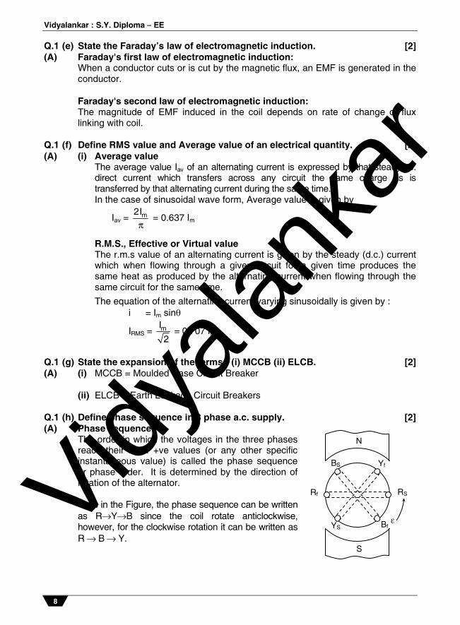
Q.1 (g) State the expansion of the terms : (i) MCCB (ii) ELCB. [2](A) (i) MCCB = Moulded Case Circuit Breaker (ii) ELCB = Earth Leakage Circuit Breakers Q.1 (h) Define phase sequence in 3 phase a.c. supply. [2](A) Phase sequence The order in which the voltages in the three phases
reach their max. +ve values (or any other specific instantaneous value) is called the phase sequence or phase order. It is determined by the direction of rotation of the alternator.
Thus in the Figure, the phase sequence can be written
as RYB since the coil rotate anticlockwise, however, for the clockwise rotation it can be written as R B Y.
N
S
BS Yf
RS Rf
YS Bf Vidy
alank
ar
Prelim Question Paper Solution
9
Q.1 (i) State the types of earthing. [2](A) Types of earthing: Plate earthing. Pipe earthing. Earth mat (mesh of metal strips) for huge power installations as generating
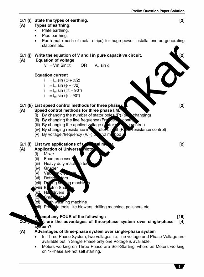
stations etc. Q.1 (j) Write the equation of V and I in pure capacitive circuit. [2](A) Equation of voltage v = Vm Sint OR Vm sin Equation current i = Im sin ( + /2) i = Im sin ( + /2) i = Im sin (t + 90) i = Im sin ( + 90) Q.1 (k) List speed control methods for three phase I.M. [2](A) Speed control methods for three phase I.M. (i) By changing the number of stator poles (P) (pole changing) (ii) By changing the line frequency (Frequency control) (iii) By changing the applied voltage (stator volta ge control) (iv) By changing resistance in the rotor circuit (Rotor resistance control) (v) By voltage /frequency (V/F) control method Q.1 (l) List two applications of universal motor. [2](A) Application of Universal Motor: (i) Mixer (ii) Food processor (iii) Heavy duty machine tools (iv) Grinder (v) Vacuum cleaners (vi) Refrigerators (vii) Driving sewing machines (viii) Electric Shavers (ix) Hair dryers (x) Small Fans (xi) Cloth washing machine (xii) Portable tools like blowers, drilling machine, polishers etc. Q.2 Attempt any FOUR of the following : [16]Q.2 (a) What are the advantages of three-phase system over single-phase
system? [4]
(A) Advantages of three-phase system over single-phase system In Three Phase System, two voltages i.e. line voltage and Phase Voltage are
available but in Single Phase only one Voltage is available. Motors working on Three Phase are Self-Starting, where as Motors working
on 1-Phase are not self starting.
Vidyala
nkar
Vidyalankar : S.Y. Diploma EE
10
For the same capacity, three phase machine occupies less space than 1-phase machine.
for the same capacity, three phase machine is lighter than 1-phase machine. 3-phase transmission line is more efficient and requires less copper than 1-
phase. Q.2(b) An alternating current given by equation i = 142.14 sin 628t. Find:
(i) RMS value (ii) Average value (iii) Frequency (iv) Time period
[4]
(A) Given equation, i = 142.14 sin 628t (1) RMS value I = Im sin t Im = 142.14, = 628
Irms = mI2
= 142.14
2 = 100.523 A
(2) Average value
Iav = m2I
= 0.637 Im = 90.543 A
(3) Frequency = 2f
f = 2
= 6282
= 100 cycles/sec.
(4) Time period
T = 1f
= 1
100 = 0.01 sec.
Q.2 (c) With the help of waveforms and phasor diagrams show the phase
relationship between voltage and current in pure inductive and purecapacitive circuits.
[4]
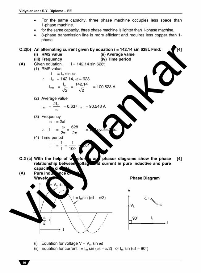
(A) Pure inductance circuit : Waveform Phase Diagram
(i) Equation for voltage V = Vm sin t (ii) Equation for current I = Im sin (t /2) or Im sin (t 90)
v = Vm sin t
I = Imsin (t /2)
2
t
90 IL
I
VL
V
Vidyala
nkar

Prelim Question Paper Solution
11
Pure capacitive circuit: Waveform Phase Diagram (i) Equation for voltage = V = Vm sin t (ii) Equation for current = I = Im sin t + /2) or Im sin (t + 90) Q.2 (d) Compare core type and shell type single phase transformer (any four
points). [4]
(A) Core Type Transformer Shell Type Transformer (i) The Winding surround the core. The core surround the windings. (ii) Magnetic Flux has only one continuous
path. Magnetic Flux is distributed into 2 paths.
(iii) Suitable for high voltage & less output.
Suitable for less voltage & high output.
(iv) Easy for repairs. Difficult for repairs. (v) Less in Weight. More in Weight. (vi) It has one window opening. It has two windows opening.
Q.2 (e) Balanced star connected load supplied from three phase 415 V,
50 Hz system, current in each phase is 20 30, 30 being w.r.t. phase voltage. Determine : (i) Vph (ii) IL (iii) cos (iv) Power
[4]
(A) (i) In star connection, Vph = LV3
= 4153
Vph = 239.6 volts (ii) In star connection, Iph = IL Iph = 20 30 A (iii) cos = cos ( 30) = 0.866 (iv) Power P = 3Vph Iph cos OR P = 3 VL IL cos
= 3 239.6 20 0.866 = 3 415 20 0.866 = 124490616 watts = 124490616 watts
90V
i
Vidyala
nkar

Vidyalankar : S.Y. Diploma EE
12
Q.3 Attempt any FOUR of the following : [16]Q.3 (a) The coil having a resistance of 10 and an inductance of 0.2
Hendry is connected to a 100 V, 50 Hz supply. Calculate : (i) the impedance of the coil (ii) the reactance of the coil. (iii) the current drawn and (iv) the phase difference between the current and the applied voltage
[4]
(A) Given : R = 10 H = 0.2 H 100 V, 50H supply = 2f = 2 50 = 100 rad/sec
(i) impedance of coil, z = R + j XL z = 10 + j 62.83
zcoil = 63.62 80.95
(ii) Reactance of coil = XL = L = (2f) L = (100 ) 0.2 = 20
XL = 62.83
(iii) Current drawn = I = vz
= 100 V
63.62 80.95
= 1.571 80.95
current drawn is = 1.571 A
(iv) the phase difference between the current and the applied voltage i.e. angle of impedance () = 80.95
Q.3 (b) Explain the difference between statically induced emf. and
dynamically induced emf. [4]
(A) Dynamically induced emf Statically induced emf (i) The emf induced by the change in
the flux linking with the coil by its motion relative to a magnetic field is called dynamically induced emf.
The emf induced by the change in the flux linking with the coil without resort to its motion relative to a magnetic field is called statically induced emf.
(ii) The magnitude of dynamically induced emf is given as e = B v sin volts where, B = Flux density = Active length v = Velocity (m/s) = Angle made by the conductor with the direction of magnetic flux.
The magnitude of statically induced emf is given as
e = d
Ndt volts
where, N = Number of turns in the coil = magnetic flux
10 0.2 H
100 V, 50 Hz
L
Vidyala
nkar

Prelim Question Paper Solution
13
(iii) Example, Electrical generators Example, Choke coil in fluorescent tube, filter circuit of a rectifier.
(iv) Dynamic emf is a motion of electrons so the emf in dynamic.
Static emf is no motion of electron.
Q.3 (c) Draw a R-L-C series circuit and phasor diagram. Also write equations. [4](A) R-L-C Series circuit with phasor diagram
Phasor Diagram: (Any one phasor diagram expected) (i) XL > XC (lagging) (ii) XC > XL (leading) (iii) XL = XC (UPF)
Equations for R-L-C series circuit :
XC = 1
2 fC
XL = 2fL
Impedance Z = 2 2L CR X X
I = VZ
cos = RZ
For XC > XL : (i) Equation for voltage V = Vm sin t (ii) Equation for current I = Im sin (t + ) For XC < XL : (i) Equation for voltage V = Vm sin t (ii) Equation for current I = Im sin (t )
Vidyala
nkar

Vidyalankar : S.Y. Diploma EE
14
For XL = XC : (i) Equation for voltage V = Vm sin t (ii) Equation for current I = Im sin t Q.3 (d) What are the different types of power in AC circuit? State its formula. [4](A) (i) Active power (P) It is the true power or real power in a ac circuit given by the product of
voltage and active component of the current. It is given by formula P = VI cos watt or kW or MW.
(ii) Reactive power (Q) It is the product of voltage and reactive component of current. It is given by
Q = VI sin volt-amp-reactive or kVAr or MVAr. (iii) Apparent power (S) It is the product of rms value of voltage and current. It is given by formula.
S = VI volt-amp or kVA orr MVA. Q.3 (e) Why transformer rating in terms of KVA not in kW? [4](A) (i) The output of transformer is limited by heating and by the losses. Two types
of losses in the transformer: (1) Iron loss, (2) Copper loss (ii) Iron loss depends on the transformer voltage (v) Copper loss is depends on
transformer current (I). (iii) As the losses depends on voltage (V) and Current (I) and almost unaffected
by load power factor. Hence transformer output is ex pressed in VA or KVA not in KW. Q.4 Attempt any FOUR of the following : [16]Q.4 (a) Draw and explain torque-speed characteristics of 3-phase I.M. [4](A) Torque-Speed characteristics
Explanation: From the above characteristics: When Slip (S) @ 0 (i.e N @ Ns) torque is almost zero at no load, hence
characteristics start from origin. As load on motor increases Slip increases and therefore torques increases.
Speed-Torque Curve for a Three-Phase Induction Motor Vidyala
nkar

Prelim Question Paper Solution
15
For lower values of load, torque proportional to slip, and characteristics will having linear nature.
At a particular value of Slip, maximum torque conditions will be obtained which is R2 = SX2.
For higher values of load i.e. for higher values of slip, torque inversely proportional to slip and characteristics will having hyperbolic nature. In short breakdown occurs due to over load.
The maximum torque condition can be obtained at any required slip by changing rotor resistance.
Q.4 (b) Compare auto-transformer and two winding transformer. (any four
points) [4]
(A) Points Autotransformer Two winding transformer (1) Symbol
(2) Number of
windings It has one winding. It has two windings.
(3) Copper saving
Copper saving takes more as compared to two winding.
Copper saving is less.
(4) Size Size is small. Size is large. (5) Cost Cost is low. Cost is high. (6) Losses in
winding Less losses takes place. More losses takes place.
(7) Efficiency Efficiency is high. Efficiency is low. (8) Regulation Regulatin is better. Regulation is poor. (9) Electrical
isolation There is no electrical isolation. Electrical isolation is present
in between primary and secondary winding.
(10) Movable contact
Movable contact is present. Movable contact is not present.
(11) Application Variac, starting of ac motors, dimmerstat.
Mains transformer, power supply, welding, isolation transformer.
Q.4 (c) Define : (i) Slip (ii) Rotor frequency
(iii) Synchronous (iv) Slip speed [4]
(A) (i) Slip The difference between synchronous speed and actual speed of the rotor
expressed as fraction or percentage of synchronous speed, is called slip.
% s = S
S
N N100
N
´
(ii) Rotor frequency The frequency of rotor emf is proportional to relative speed (NS N) of
rotating stator field with respect to the rotor. It is given by fr = slip x supply frequency = s.f
Vidyala
nkar

Vidyalankar : S.Y. Diploma EE
16
(iii) Synchronous speed The speed of rotating magnetic field produced by stator winding is called as
synchronous speed. It is given by
Ns = 120 fP
(iv) Slip speed The relative speed between rotor and rotating magnetic field is called as slip-
speed. It is given by (NS N). Q.4 (d) Compare three phase squirrel cage induction motor and slip ring
induction motor based on starting torque, starting current, powerfactor and maintenance cost.
[4]
(A) Parameters Squirrel cage I.M. Slip ring Slip ring I.M.
starting torque Low High with rotor resistance starter. starting current More Less power factor Better running Better starting maintenance cost Less More
Q.4 (e) State the principle of operation of an universal motor. Give any two
applications. [4]
(A) Operating principle is the interaction of the main field and field due to current in the armature conductors to produce force/torque for motion. The force is directly proportional to the product of main flux and armature current.
Applications vacuum cleaners drill machine food mixers blenders domestic sewing machine hair dryers etc. Q.5 Attempt any FOUR of the following : [16]Q.5 (a) A single phase transformer has 350 primary and 1050 secondary
turns. The net crosssectional area of core is 55 cm2. If primarywinding is connected to a 400 V, 50 Hz, 1phase supply. Calculate. (i) Maximum value of flux density in the core. (ii) Voltage induced in the secondary.
[4]
(A) Given data : N1 = 350, N2 =1050, a = 55 cm2 = 55*10-4 m2. Bm =? and V1 =?
Vidyala
nkar
Prelim Question Paper Solution
17
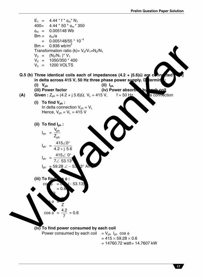
E1 = 4.44 * f * m* N1 400= 4.44 * 50 * m * 350 m = 0.005148 Wb Bm = m/a = 0.005148/55 * 104 Bm = 0.936 wb/m2 Transformation ratio (k)= V2/V1=N2/N1 V2 = (N2/N1 )* V1 V2 = 1050/350 * 400 V2 = 1200 VOLTS Q.5 (b) Three identical coils each of impedances (4.2 + j5.6) are connected
in delta across 415 V, 50 Hz three phase power supply. Determine : (i) Vph (ii) Iph (iii) Power factor (iv) Power absorbed by each coil
[4]
(A) Given : Zph = (4.2 + j 5.6), VL = 415 V, f = 50 Hz, Delta connection
(i) To find Vph : In delta connection Vph = VL Hence, Vph = VL = 415 V
(ii) To find Iph :
Iph = ph
ph
V
Z
Iph = °415 0
4.2 j 5.6
Iph = °°
415 07 53.13
Iph = 59.28 53.13 Amp
(iii) To find cos : cos = cos ( 53.13) = 0.6 OR
cos = RZ
cos = 4.27
= 0.6
(iv) To find power consumed by each coil Power consumed by each coil = Vph Iph cos = 415 59.28 0.6 = 14760.72 watt = 14.7607 kW
Vidyala
nkar
Vidyalankar : S.Y. Diploma EE
18
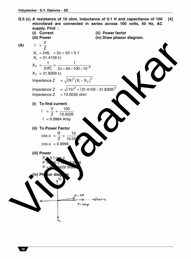
Q.5 (c) A resistance of 10 ohm, inductance of 0.1 H and capacitance of 100microfarad are connected in series across 100 volts, 50 Hz, ACsupply. Find : (i) Current (ii) Power factor (iii) Power (iv) Draw phasor diagram.
[4]
(A) I = VZ
XL = 2fL = 2 50 0.1 XL = 31.4159
XC = 1
2 fC = 6
12 50 100 10´ ´ ´
XC = 31.8309
Impedance Z = 2 2l CR X X
Impedance Z = 2 210 31.4159 31.8309 Impedance Z = 10.0035 ohm (i) To find current
I = VZ
= 100
10.0035
I = 9.9964 Amp (ii) To Power Factor
cos = RZ
= 10
10.0035
cos = 0.9996 (iii) Power P = V I cos P = 100 10 0.9996 P = 999.6426 Watt
(iv) Phasor diagram
Vidyala
nkar
Prelim Question Paper Solution
19
Q.5 (d) A 100 kVA, single phase transformwer has a full load Cu loss of3 kW and iron loss of 2 kW. Find the efficiency of the transformer athalf and full load at unity power factor.
[4]
(A) Efficiency at half load
HL = 2
1 kVA cos2 100
1 1kVA cos Iron losses copper losses2 2
´ ´´
´ ́
HL =
1 100 12 100
1 100 1 2 0.752
´ ´´
´ ´
HL = 94.79% Efficiency at Full Load
FLL = kVA cos
100kVA cos Iron losses copper losses
´´
´
FLL = 100 1
100100 1 2 3
´´
´
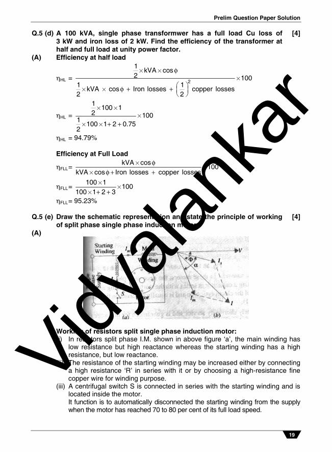
FLL = 95.23% Q.5 (e) Draw the schematic representation and state the principle of working
of split phase single phase induction motor. [4]
(A)
Working of resistors split single phase induction motor: (i) In resistors split phase I.M. shown in above figure ‘a’, the main winding has
low resistance but high reactance whereas the starting winding has a high resistance, but low reactance.
(ii) The resistance of the starting winding may be increased either by connecting a high resistance ‘R’ in series with it or by choosing a high-resistance fine copper wire for winding purpose.
(iii) A centrifugal switch S is connected in series with the starting winding and is located inside the motor.
It function is to automatically disconnected the starting winding from the supply when the motor has reached 70 to 80 per cent of its full load speed.
Vidyala
nkar

Vidyalankar : S.Y. Diploma EE
20
Q.6 Attempt any FOUR of the following : [16]Q.6 (a) Write four applications of stepper motor. [4](A) Applications of stepper motor: (1) Suitable for use with computer controlled system. (2) Widely used in numerical control of machine tools. (3) Tape drives (4) Floppy disc drives (5) Computer printers (6) X-Y plotters (7) Robotics (8) Textile industries (9) Integrated circuit fabrication (10) Electric watches (11) In space craft's launched for scientific explorations of planets. (12) In the production of science friction movies (13) Automotive (14) Food processing (15) Packaging Q.6 (b) Define fuse. State the necessity of fuse. Write rating of fuses used in
labs and mention the classification of fuses. [4]
(A) Fuse: a fuse is a short piece of metal, inserted in the circuit, which melts when excessive current flows through it and thus breaks the circuit.
Necessity of fuse: It provides short circuit protection. It provides overload protection. Rating of fuses: 2 A, 3 A, 5 A, 6A, 10 A, 16 A etc. Classification of fuse: Low voltage fuses-
Semi-enclosed rewirable fuse High rupturing capacity (HRC) cartridge fuse. HRC fuse with tripping device High voltage fuse Cartridge type fuse Liquid type fuse Metal clad fuse
Q.6 (c) State specifications and two applications of isolation transformer andradiofrequency transformer.
[4]
(A) Isolation Transformer Radio frequency transformer Specifications Power rating 0.125,0.25, 0.5,...,
phase, frequency: 47 - 50 Hz. Frequency in MHz, Power rating, voltage, current etc.
Applications 1. Areas where common mode noise is generated.
1. To transfer rf signal from one circuit to another circuit
Vidyala
nkar
Prelim Question Paper Solution
21
2. Protect sensitive equipment from unwanted voltage spikes on primary side.
2. Impedance matching to achieve maximum power
transfer and to suppress undesired signal reflection.
3. Used in electronic circuits for isolation.
3. Voltage, current step-up or step-down.
4. Used in circuits to avoid audio and video distortions.
4. DC isolation between circuits while affording efficient AC transmission
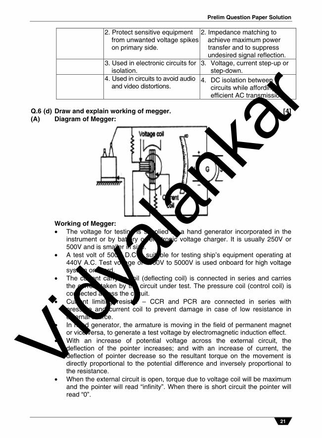
Q.6 (d) Draw and explain working of megger. [4](A) Diagram of Megger:
Working of Megger: The voltage for testing is supplied by a hand generator incorporated in the
instrument or by battery or electronic voltage charger. It is usually 250V or 500V and is smaller in size.
A test volt of 500V D.C is suitable for testing ship’s equipment operating at 440V A.C. Test voltage of 1000V to 5000V is used onboard for high voltage system onboard.
The current carrying coil (deflecting coil) is connected in series and carries the current taken by the circuit under test. The pressure coil (control coil) is connected across the circuit.
Current limiting resistor – CCR and PCR are connected in series with pressure and current coil to prevent damage in case of low resistance in external source.
In hand generator, the armature is moving in the field of permanent magnet or vice versa, to generate a test voltage by electromagnetic induction effect.
With an increase of potential voltage across the external circuit, the deflection of the pointer increases; and with an increase of current, the deflection of pointer decrease so the resultant torque on the movement is directly proportional to the potential difference and inversely proportional to the resistance.
When the external circuit is open, torque due to voltage coil will be maximum and the pointer will read “infinity”. When there is short circuit the pointer will read “0”.
Vidyala
nkar

Vidyalankar : S.Y. Diploma EE
22
Q.6 (e) Draw the schematic representation and state the principle of workingof servo motor.
[4]
(A) Schematic representation :
Principle of working of servo motor: There are some special types of application of electrical motor where rotation of the
motor is required for just a certain angle not continuously for long period of time. For these applications some special types of motor are required with some special arrangement which makes the motor to rotate a certain angle for a given electrical input (signal). Such motors can be ac or dc motors. When controlled by servo mechanisms are termed as servomotors.
These consist of main and control winding and squirrel cage / drag cup type
rotors. Vr is the voltage applied to the main or reference winding while VC is that applied to control winding which controls the torque- speed characteristics. The 900 space displacement of the two coils/windings and the 900 phase difference between the voltages applied to them result in production of rotating magnetic field in the air gap due to which the rotor is set in motion. The power signals can be fed from servo amplifiers either to the field or armature depending upon the required characteristics.
OR Working of AC Servomotor: The control Phase is usually supplied from a servo amplifier. The speed and torque of the rotor are controlled by the phase difference
between the control voltage and the reference phase voltage. The direction of rotation of the rotor can be reversed by reversing the phase
difference, from leading to lagging (or vice versa) between the control phase voltage and the reference phase voltage.
Vidyala
nkar