direct verification of the ion-neutral synergism during hydrocarbon film growth
TRANSCRIPT

JOURNAL OF APPLIED PHYSICS VOLUME 93, NUMBER 6 15 MARCH 2003
Direct verification of the ion-neutral synergism during hydrocarbonfilm growth
C. Hopf, A. von Keudell,a) and W. JacobCentre for Interdisciplinary Plasma Science, Max-Planck-Institut fu¨r Plasmaphysik, EURATOM Association,Boltzmannstrasse 2, 85748 Garching, Germany
~Received 26 August 2002; accepted 10 December 2002!
Elementary ion-induced surface processes during plasma deposition of amorphous hydrogenatedcarbon films are studied in a particle-beam experiment employing sources for noble gas ions andCH3 radicals. Two processes govern film formation:~1! Ion-assisted film growth: Incident ionsdisplace surface-bonded atoms and create dangling bonds which then serve as chemisorption sitesfor incident radicals, and~2! Ion-induced hydrogen release: Incident ions alter the film compositionby preferential removal of bonded hydrogen in the subsurface of the growing film. It is shown thatboth elementary processes are in quantitative agreement with displacement yields as calculated bycomputer simulations. ©2003 American Institute of Physics.@DOI: 10.1063/1.1543247#
di,
pen-heut
cae
testo
ens
enopeonntly
lyen
is
ithedm
oning
agy,hison-iveasorticthe
ol-ing
pro-calbyionof
ta-aseperut-ss
tee-
uslyeu-icho ao-
ur.tenly
I. INTRODUCTION
Amorphous hydrogenated carbon~a-C:H! films are usu-ally deposited from hydrocarbon gas discharges. Depenon external parameters like feed gas, discharge pressureplied bias voltage, or substrate temperature, the film proties vary from polymerlike films with a high hydrogen cotent to hard films with a low hydrogen content. Since tacronyma-C:H is mostly used to denote hard amorphohydrocarbon layers, we will use the acronym C:H insteadcharacterize the whole variety of plasma-deposited hydrobon films. Hard films possess extraordinary material propties, which lead to a wide range of applications.1 Optimiza-tion of the deposition process with respect to growth rathickness homogeneity, and desired material property is ually achieved by empirical methods. However, in ordertailor the film properties in a predictive manner, a fundamtal understanding of the microscopic deposition processefavorable.
Beyond controversy is the fact that ion bombardmduring plasma deposition strongly influences the final prerties of the film. Hardness, density, and refractive indincrease with increasing ion energy while the hydrogen ctent decreases.2–4 The strong influence of ion bombardmeon film composition and structure can be roughunderstood:5 An incident ion displaces predominantbonded hydrogen in the film due to the lower displacemthreshold energy for hydrogen compared to carbon.6 Fourindividual processes can be initiated by this ion-induced dplacement of target atoms in C:H films.
~1! Mechanism A, hydrogen depletion: Due to the lower dis-placement threshold for hydrogen compared wcarbon,5 predominantly bonded hydrogen is displacwithin a collision cascade. Displaced hydrogen atorecombine locally forming H2 molecules, which diffuseto the surface and desorb.7 This subsurface H2 formation
a!Electronic mail: von–[email protected]
3350021-8979/2003/93(6)/3352/7/$20.00
Downloaded 14 Apr 2003 to 134.147.148.72. Redistribution subject to A
ngap-r-
sor-r-
,u-
-is
t-x-
t
-
s
leads to depletion of the hydrogen content within the ipenetration range and to cross linking of the remaincarbon network.
~2! Mechanism B, physical sputtering: If the projectile or adisplaced atom~5recoil! transfers sufficient energy tosurface atom to overcome its surface binding enerphysical sputtering occurs. The threshold energy for tprocess depends on the kinematics of at least two csecutive collision events: In a first or several consecutcollisions, the momentum of the incident projectile hto be reversed. In a following collision, the projectilea recoil has to transfer enough of its remaining kineenergy to a surface atom to cause its release fromsolid. The efficiency of the energy transfer in these clisions events depends on the masses of the collidatoms. In case of a large mass difference betweenjectile and target atom, the threshold energy for physisputtering is rather high. The sputtering of carbonincident argon ions requires, for example, at least anenergy of 58 eV,8 although the surface binding energycarbon is only 4.5 eV.6
~3! Mechanism C, chemical sputtering: C:H films can beetched by either a flux of reactive ions or by a simulneous flux of ions and reactive neutrals. The latter cleads to a significant enhancement of the etch rateion and to a reduction of the threshold energy for sptering in comparison to physical sputtering. This proceis termed ‘‘chemical sputtering’’: Incident ions creabroken bonds within a collision cascade via displacment of target atoms. The defects are instantaneopassivated by the simultaneously incident reactive ntrals. Thereby, stable erosion products are formed, whthen diffuse to the surface and desorb. This leads tdrastically lowered threshold energy, because no mmentum reversal of the incident projectile has to occAdditionally, a significant enhancement of the absoluyields results, because the erosion products do not o
2 © 2003 American Institute of Physics
IP license or copyright, see http://ojps.aip.org/japo/japcr.jsp

eta
oiotep
tnsr-enuttendcog
mnten
tos
fohn-hiH
celow
o
gs. Acam
hyned
mrgalyrth
foethin
x
cesaryare
gleex-
ited
rea
d
e isup
n-
nion-
en-
ig.
3353J. Appl. Phys., Vol. 93, No. 6, 15 March 2003 Hopf, von Keudell, and Jacob
originate from the physical surface, but from within thwhole ion penetration range. This was studied in deelsewhere.9,10
~4! Mechanism D, surface activation: If a surface atom isdisplaced, an active surface site, such as a dangling b~DB!, remains. The DB’s then serve as chemisorptsites for incident radicals from the plasma. This two-sprocess of DB creation followed by radical chemisortion can be regarded as ‘‘ion-assisted’’ film growth.
The quantitative contributions of all these processesfilm growth are often estimated by computer simulatiosuch as theTRIM.SP code.11 For example, the process of suface activation is quantified by calculating the displacemyield per incident ion at the physical surface. The absolvalues, however, depend sensitively on the input parameof the TRIM.SP code such as displacement and surface biing energies. These are theoretically estimated from theresponding binding energies of the target atoms in sinmolecules or single crystals.11 Alternatively, they can also beevaluated experimentally by measuring the change of aterial property upon particle irradiation. The displacemeenergy for carbon in graphite, for example, has been demined to be;24.7 eV by measuring the change in the coductivity of graphite upon electron irradiation.12
However, up until now, it is an open question aswhether these input parameters, as determined from conering simple molecules or single crystals, are still validamorphous multicomponent targets such as C:H films. Tis especially important for the quantitative prediction of ioinduced effects during plasma-assisted film growth. In tarticle, this question is addressed using a quantified C3
radical beam and a quantified ion beam to study ion-indusurface processes. Thereby, a probe is provided which althe direct measurement of ion-induced surface activationthe basis of the known absolute cross section for CH3 chemi-sorption at a surface dangling bond.
II. EXPERIMENT
Film growth is studied in an experiment employinbeams of energetic He1 ions and thermal methyl radical(CH3). Figure 1 shows a schematic of the experimentUHV chamber is equipped with an ion gun and a radisource producing methyl radicals. The ion and radical beamerge at the sample position where they interact with adrocarbon film. This film is deposited from an rf methadischarge in a preparation chamber and then transferrethe main chamber without breaking the vacuum.
The ion gun is a commercial Colutron G2-D systeIons are generated in a hot filament sustained dc dischaaccelerated to 1 keV, focused with an Einzel lens, and mfiltered in a Wien filter. In a deceleration optics assembthey are then decelerated to the derived energy. In ordeprevent 1 keV charge exchange neutrals from reachingsubstrate, the ion beam is electrostatically bent by 2° beentering the deceleration optics. The ions impinge perpdicularly on the surface. The focus of the ion beam atsample position is monitored with a microchannel plateconjunction with a phosphor screen. The absolute ion flu
Downloaded 14 Apr 2003 to 134.147.148.72. Redistribution subject to A
il
ndnp-
o,
ters-r-
le
a-tr--
id-ris
s
ds
n
ls-
to
.e,
ss,toe
ren-e
is
measured with a Faraday cup. The methyl source produCH3 by decomposing azomethane in a tungsten capillheated to 1150 K. Details of the radical beam sourcedescribed elsewhere.13
Film growth and erosion are monitored byin situ real-time ellipsometry at a wavelength of 632.8 nm and an anterms of incidence of 75.8°. The ellipsometry data arepressed in terms of the ellipsometric anglesC andD and areevaluated by comparison to an optical model of the deposfilms. The optical model yields growth rates in nm s21,which are converted to incorporated carbon atoms per aand time by using a carbon atom densityr5931022 cm23. Such a carbon density is typical of so-callehard carbon films deposited in our experiments.2 For all re-sults described in the following, the substrate temperatur;320 K. A detailed description of the experimental setwill be published elsewhere.14
III. RESULTS AND DISCUSSION
A. Film formation
Figure 2 shows the original ellipsometry data during ioassisted film growth by a simultaneous flux of He1 ions andCH3 radicals. The ion energy is 200 eV@Fig. 2~a!#, 400 eV@Fig. 2~b!#, and 800 eV @Fig. 2~c!#. The ion flux is 231013 cm22 s21 and the CH3 flux 2.101431014 cm22 s21.Both beams are switched on@point 1 in Fig. 2~c!# andswitched off@point 4 in Fig. 2~c!# simultaneously. It can beseen that the measuredC, D values follow a characteristics-shaped trajectory with two turning points@marked as points2 and 3 in Fig. 2~c!#. The shift to larger values inC andlower values inD between points 3 and 4 is indicative of aincrease in film thickness and therefore corresponds toassisted film growth. The initial s-shaped part of theC, Dtrajectory becomes more pronounced with increasing ionergy.
TheC, D trajectory of the experiment using 800 eV He1
ions is compared with two optical models, as shown in F
FIG. 1. Schematic of the experimental setup.
IP license or copyright, see http://ojps.aip.org/japo/japcr.jsp

a
.
-on
acby
e
th
hefo
onH
x
derteelf-H
essace
Re-b-is-
theth
is-by
and
t at
ou
int
ous
al
nm
,
3354 J. Appl. Phys., Vol. 93, No. 6, 15 March 2003 Hopf, von Keudell, and Jacob
3. According to the first optical model, a C:H film withthickness of 0.8 nm and a refractive index ofn51.92 i0.01 is formed in a first phase~i! between points 1 and 2The average growth rate is 5.631013 cm22 s21. In a secondphase~ii !, a shift of theC, D trajectory from points 2 to 3occurs. In a third phase~iii !, steady-state film growth between points 3 and 4 is observed. According to the secoptical model, a film with a refractive index ofn52.42 i0.35 at a deposition rate of only 1.931012 cm22 s21
grows. The latter optical model assumes that an interfbetween the initial C:H film and the new film has formedthe combined flux of He1 ions and CH3 radicals. This inter-face reaches 4.3 nm below the initial film surface~distancebetween points 1 and 1* in Fig. 3! and is assumed to havthe same optical constants as the film growing in phase~iii !.The two optical models are motivated by the assumptiona characteristic hydrogen depth profilecH(x) in the filmevolves during the three phases~i! to ~iii !, as described in thefollowing:
~i! In the first phase~between point 1 and 2 in Fig. 3!,incident He1 ions displace bonded hydrogen at tsurface, which leaves behind chemisorption sitesincident CH3 radicals. This ‘‘ion-assisted filmgrowth’’ causes a high growth rate. The incorporatiof hydrogen-rich hydrocarbon precursors such as C3
initially leads to a film with a lower refractive indeof n51.92 i0.01 compared withn52.42 i0.35 forthe steady-state film growth in phase~iii !. This fast
FIG. 2. Ellipsometry data for the ion-assisted film growth by a simultaneflux of CH3 radicals and He1 ions. The ion energy is 200~a!, 400 ~b!, and800 eV~c!. The ion and CH3 beams are switched on simultaneously at po1 and switched off at point 4. The turning points of theC, D trajectory areindicated as points 2 and 3. The ion flux is 231013 cm22 s21 and the CH3flux 231014 cm22 s21.
Downloaded 14 Apr 2003 to 134.147.148.72. Redistribution subject to A
d
e
at
r
film growth in phase~i!, however, does not proceebeyond a film thickness of 0.8 nm and only a top laywith high hydrogen content is formed. We postulathat this top layer is created and maintained by a slimiting process based on the balance between C3
chemisorption and chemical sputtering. The procof chemical sputtering corresponds to the subsurfformation of stable CxHy species, which then diffuseto the surface and desorb, as described herein.cently, it was shown that the production of these susurface species is proportional to the ion-induced dplacement yield of bonded target atoms timeshydrogen content in the corresponding depinterval.9 Figure 4 shows carbon and hydrogen dplacement yields per depth interval as calculatedTRIM.SP for He1 ion bombardment of C:H films witha density of 2 g cm22 and a H content ofcH50.3. Itcan be seen that the displacement yield for carbonhydrogen has a pronounced maximumbelow the sur-face: The maximum yield for displacing carbon is adepth of ;1 nm for an ion energy of 200 eV, bu
s
FIG. 3. Ellipsometry data for the ion-assisted film growth by a simultaneflux of CH3 radicals and He1 ions at 800 eV@same data as Fig. 2~c!#. Theopen circles denote an optical model for growth of a film with opticconstantsn51.92 i0.01 and the open squares for growth of a film withn52.42 i0.35.
FIG. 4. Carbon and hydrogen displacement yields per depth interval of 1from TRIM.SP calculations for He1 ion bombardment of C:H films with adensity of 2 g cm22 and a H content ofcH50.3 at ion energies of 200, 400and 800 eV.
IP license or copyright, see http://ojps.aip.org/japo/japcr.jsp
afil.alde
fae
heoisu
su
ra
mtoehecis
on-ig
ei
rs
.Womte
n
1
en
rinntu
hu
ales
roneca
setialser-
thefor
Inonal,of
he
lmnted
ur-
csts
ts
en
ofn-
ro-nce,in-ta,tiveg.eV
ub-wthbe-ery
en
3355J. Appl. Phys., Vol. 93, No. 6, 15 March 2003 Hopf, von Keudell, and Jacob
increases to;5 nm for an ion energy of 800 eV. Asconsequence, the topmost layers of the depositedare not efficiently removed by chemical sputteringOnly if the thickness of the top layer becomes equivlent to the depth of the maximum displacement yiethe rate of CH3 chemisorption at the physical surfacstarts to be compensated by the rate of subsurformation of CxHy species and their release. As a rsult, a top layer is initially formed by CH3 chemisorp-tion with a thickness depending on the depth of tmaximum displacement yield and thus dependingthe ion energy. The growth rate in the beginninghigh, because chemical sputtering is inefficient, bdecreases drastically when chemisorption at theface starts to be compensated by subsurface CxHy re-lease.This interpretation of the data is supported by seveexperimental observations:~a! The refractive index ofthe top layer is much lower than that of the C:H fildeposited in steady state. This implies that thelayer is hydrogen rich, because the refractive indscales inversely with the hydrogen content in tfilm.2 ~b! The steady-state growth rate is about a fator 30 lower than the growth rate of the top layer. Thsupports the assumption that, at the onset of iassisted film growth, CH3 chemisorption is not compensated by chemical sputtering and thus a hgrowth rate is observed.~c! The thickness of the toplayer scales with the ion energy, as described herThis is supported by the data shown in Figs. 2~a!–2~c!. With decreasing ion energy, the initial shift ofC,D between points 1 and 2 becomes smaller andalmost invisible at an ion energy of 200 eV.
~ii ! Whereas the formation of the top layer during the fiphase is completed after 180 s, the shift inC, D dur-ing the second phase~between points 2 and 3 in Fig3! is ten times slower and takes about 1800 s.assume that during this transient phase, the ion bbardment causes a depletion of the hydrogen conof the initial bulk C:H film. This hydrogen depletionoccurs within the penetration range of the incideions. In the case of 800 eV He1 ion bombardment ofa hard C:H film, the ion penetration range is aboutnm with a maximum displacement yield at 5 nm.The optical constants of C:H films are strongly corrlated to the film density and to the hydrogen conteas has been thoroughly investigated by measubulk C:H films.2 Therefore, a change in the H contealso leads to a change of the refractive index thcausing a corresponding variation of theC, D values.After switching on the particle beams, film growtand hydrogen depletion in the subsurface set in simtaneously. During transient phases~i! and~ii !, a modi-fied surface layer is formed which becomes visiblea characteristic variation in the ellipsometric angbetween points 1 and 3 in Fig. 3. AC, D trajectory forstationary film growth is reached as soon as the pcess of ion-induced hydrogen depletion reaches asteady state. This is taken into account in the opti
Downloaded 14 Apr 2003 to 134.147.148.72. Redistribution subject to A
m
-,
ce-
n
tr-
l
px
-
-
h
n.
is
t
e-
nt
t
0
-tg
s
l-
s
-wl
model describing steady-state film growth in pha~iii !. We assume that the interface between the iniC:H film and the growing steady-state film in pha~iii ! is a modified layer. This modified layer is geneated within the original C:H layer by ion-induced Hrelease due to the ion bombardment. Assumingsame optical constants for this modified layer asthe material grown in phase~iii ! (n52.42 i0.35), weobtain a thickness of this modified layer of 4.3 nm.other words, ion bombardment during the transitiphase~ii ! converts a certain thickness of the originC:H layer into a material with lower H content andtherefore, higher refractive index. The thicknessthis modified interface is in good agreement with tion penetration range calculated byTRIM.SP. A moredetailed optical model describing simultaneous figrowth and subsurface hydrogen release is preselater.
~iii ! After the ion-induced hydrogen release in the subsface of the initial C:H film is completed, aC, D tra-jectory ~between points 3 and 4 in Fig. 3! for station-ary C:H film growth is observed. The characteristiof theC, D trajectory depend on the optical constanof the deposited C:H film and, thus, mainly on ihydrogen content.2,5 The film composition is deter-mined by the balance between the rate of hydrogand carbon incorporation via CH3 chemisorption andthe ion-induced hydrogen removal rate. The rateCH3 incorporation decreases with increasing ion eergy, as will be shown later, whereas the total hydgen displacement yield increases. As a consequethe hydrogen content is expected to decrease withcreasing ion energy. This is corroborated by the dasince a decreasing H content causes higher refracindices: Using optical models similar to those in Fi3, evaluation of the films deposited at 200 and 400He1 ion energy yields n52.2–i0.13 and n52.33–i0.2, respectively.
In principle, all processes such as top layer formation, ssurface hydrogen release, as well as steady-state film grooccur simultaneously. These individual processes onlycome visible in the experiments, because they all have v
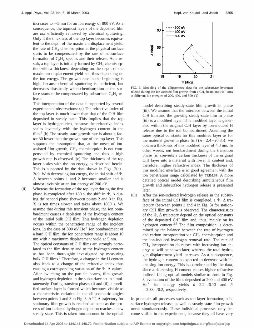
FIG. 5. Modeling of the ellipsometry data for the subsurface hydrogrelease during the ion-assisted film growth from a CH3 beam and He1 ionsat different ion energies of 200, 400, and 800 eV.
IP license or copyright, see http://ojps.aip.org/japo/japcr.jsp
ten
rfac-t tr
es
twthn
is
or
ofdsit
f
rthio
-wts
iobbyac
Htialhe:Hat
r-e
for
fea-
me0
thex-ns
m
es
re-
all
t
fort-to
3356 J. Appl. Phys., Vol. 93, No. 6, 15 March 2003 Hopf, von Keudell, and Jacob
different rates and reach saturation after different time invals: Top layer formation occurs at the fastest rate areaches saturation after a few minutes, whereas subsuhydrogen release occurs at an intermediate rate and reasaturation only after;30 min. Steady-state film growth occurs at the slowest rate. Summarizing, we can state thathree-phase model is able to explain the general behaviothe measuredC, D trajectories as well as the different ratof film formation.
The presented data are quantitatively evaluated withrather simple optical models, as depicted in Fig. 3. Infollowing, a more detailed optical model for the transiebehavior during phase~ii ! is presented.
B. Subsurface hydrogen release
During phase~ii !, incident He1 ions displace bondedhydrogen within their penetration range. The hydrogen dplacement yield is calculated byTRIM.SP for a given hydro-gen content,cH , and ion energy,Eion . In the following, theyieldsYdispl.H(x,cH ,Eion) are expressed as the probability fan incident ion to displace a target atom at a depthx in adepth intervalDx50.2 nm corresponding to the thicknessabout one monolayer. The displacement energy for bonhydrogen is taken to be 2.5 eV.6 Displaced hydrogen atomrecombine with adjacent hydrogen atoms in the network wa probabilityprecombinationforming H2 molecules, which dif-fuse to the surface and desorb.7 The dependence oYdispl.H(x,cH) on cH is approximated toYdispl.H(x,cH)5Ydispl.H(x,cH,0)3cH(x)/cH,0 with cH,050.3. This is reason-able sinceTRIM.SP calculations show that the probability fohydrogen displacement scales, to first order, linearly withH content. The change of the hydrogen concentratcH(x,t) in time is given by
n0
dcH~x,t !
dt52precombinationcH~x,t ! j ions
3Ydispl.H~x,cH,0,Eion!cH~x,t !
cH,0, ~1!
where j ions denotes the ion flux andn0 the areal density oflattice sites ofn05231015 cm22.
The ion-induced release of H2 molecules in the subsurface region is counteracted by the ion-assisted film grovia chemisorption of CH3 at surface DB’s. The growth rate iproportional to the surface DB density, the CH3 chemisorp-tion cross section at a DB, and the incoming flux of CH3.The DB coverage results from the balance between theinduced creation of surface DB’s and their consumptionCH3 chemisorption. The ion-induced DB creation is giventhe displacement yield of hydrogen at the physical surfYdispl.H(0)5Ydispl.H(0,cH,0)3cH(0,t)/cH,0. The balanceequation for the dangling bond coverageQDB yields
n0
dQDB
dt5 j ionsYdispl.H~0!~12QDB!
2 j CH3sCH3 ,additionn0QDB . ~2!
The ion-assisted growth rate is given by
Downloaded 14 Apr 2003 to 134.147.148.72. Redistribution subject to A
r-dce
hes
heof
oet
-
ed
h
en
h
n-y
e
G5sCH3 ,additionj CH3QDBn0 . ~3!
Based on Eqs.~1!–~3!, the evolutioncH(x,t) in discretetime stepsDt is derived. The delicate balance between C3
chemisorption and chemical sputtering leading to the iniformation of a top layer is not considered in this model. Tconversion of the hydrogen-rich top layer into the bulk Cfilm during phase~i! is, therefore, modeled by assuming thCH3 chemisorption, as given by Eq.~3!, is equivalent to thedeposition of a C:H film with a thicknessG3Dt and a hy-drogen contentcH50.3. The increase of film thickness coresponds to a change of the origin of the depth coordinatx.The hydrogen displacement yieldYdispl.H(x,cH ,Eion) for He1
ion bombardment of a C:H film withcH50.3 is calculated byTRIM.SP. Further input parameters are the cross sectionschemisorption of CH3, sCH3 ,addition52.4 Å2 15,16. Finally, theprobability precombination is determined from comparison othe results of the optical model discussed later with the msured data. This yieldsprecombination50.1.
The optical model is developed on the basis of the tievolution ofcH(x,t), which is discretized in space into 10individual 0.2 nm thick layersl with a H contentcH,l(t). Theoptical constantsnl5nl2 ik l for each layerl are derivedfrom the measured dependence of the refractive index onH contentcH .2 This dependence is approximated and etrapolated to low hydrogen contents by analytical [email protected] exp(cH,l20.28/0.15)# for the real part andk [email protected] exp(cH,l10.1/0.08)#21 for the imaginary part.
The stack of layers consisting of 100 individual 0.2 nthick layers with optical constantsnl and k l on top of theinitial C:H film is used to calculate the ellipsometric anglC, D. The initial film thickness is 33 nm.
Based on this optical model, theC(t), D(t) trajectoriesfor different ion energies are calculated by using the corsponding distributionsYdispl.H(x,cH ,Eion). The modeling re-sults are shown in Fig. 5. They agree well with the overbehavior of the measuredC(t), D(t) ~shown in Figs. 2 and3! trajectories during phase~ii ! and~iii !. The model does no
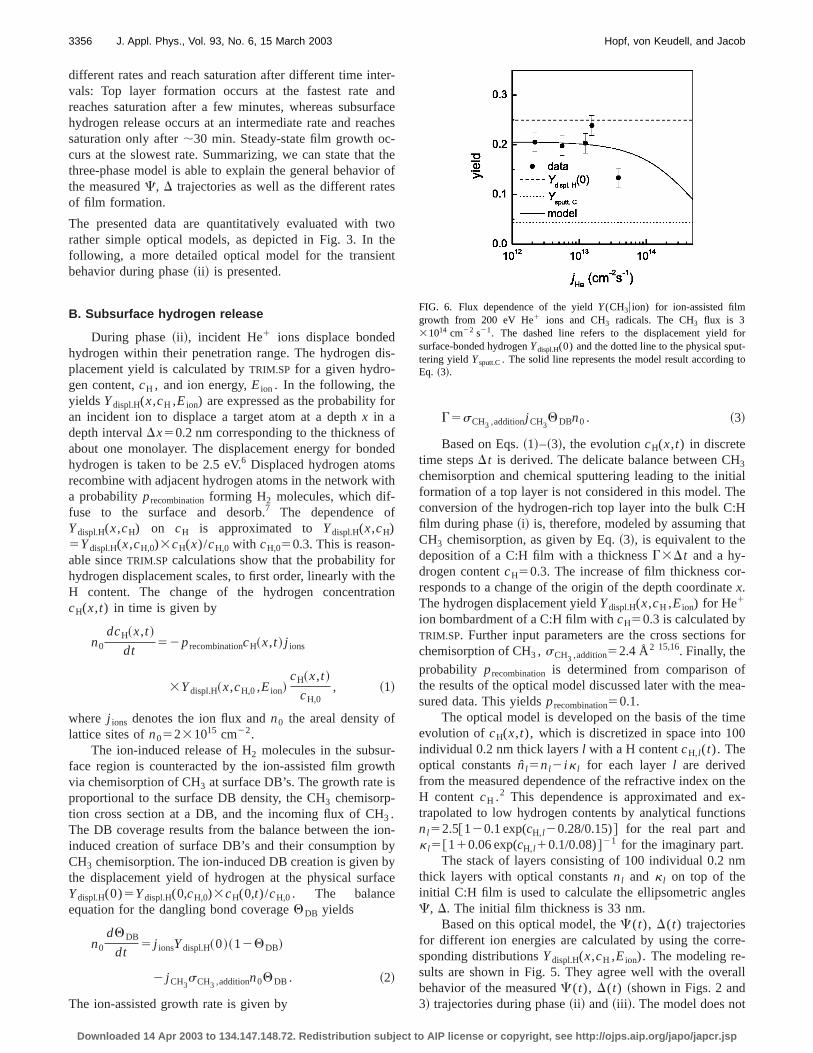
FIG. 6. Flux dependence of the yieldY(CH3u ion) for ion-assisted filmgrowth from 200 eV He1 ions and CH3 radicals. The CH3 flux is 331014 cm22 s21. The dashed line refers to the displacement yieldsurface-bonded hydrogenYdispl.H(0) and the dotted line to the physical sputering yieldYsputt.C. The solid line represents the model result accordingEq. ~3!.
IP license or copyright, see http://ojps.aip.org/japo/japcr.jsp
g
b
nthdigete
tor-
nf i
istha
esn
iva.in
leo
ionlm
reowth
wthces
stedn-
n-
sr-
eof
deda-to
n ton-enge
7.
f theion
t
t ofee isf the
naspo-ent
3357J. Appl. Phys., Vol. 93, No. 6, 15 March 2003 Hopf, von Keudell, and Jacob
reproduce the initial formation of the top layer durinphase~i!, since its creation mechanism is neglected.
Three experimental observations are well reproducedthe optical model:~a! The shift of C, D toward lowerCvalues during phase~ii ! is more pronounced at higher ioenergies. According to the model, this shift is caused bysubsurface hydrogen depletion. At higher ion energy, theplacement yield as well as the penetration range is larwhich leads to a larger thickness of the hydrogen deplesubsurface region and, therefore, to a larger variation ofC, Din phase~ii !. ~b! The characteristics of theC, D shift duringphase~ii ! change with increasing ion energy. Accordingthe optical model, a shift inC corresponds mainly to subsuface hydrogen depletion, whereas a shift inD correspondsmainly to film growth. At high ion energies, the hydrogedepletion is more pronounced while the growth rate itselreduced. As a consequence, the shift inC is larger than theshift in D. This is reversed for theC, D trajectory as mea-sured for low ion energies.~c! The C, D trajectories duringphase~iii ! indicate that a film with higher refractive indexdeposited at higher ion energies. This is consistent withaforementioned balance between hydrogen incorporationhydrogen release during film growth. At high ion energithe deposited C:H film exhibits a lower hydrogen conteresulting in a higher refractive index.
In summary, the processes of ion-induced surface acttion, chemical sputtering, and subsurface hydrogen relecan consistently explain the observed ellipsometry datashould be mentioned, however, that this optical modelcannot be used to uniquely determinecH(x,t). A C(t), D(t)trajectory depends on the optical properties of a compstack of layers and thereby on the whole distributioncH(x). Different distributionscH(x,t) may result in the sameC(t), D(t) trajectory. Direct measurement ofcH(x) requiresother diagnostics, e.g., elaborate implementations ofbeam analysis methods with very good resolution for fidepth and composition.
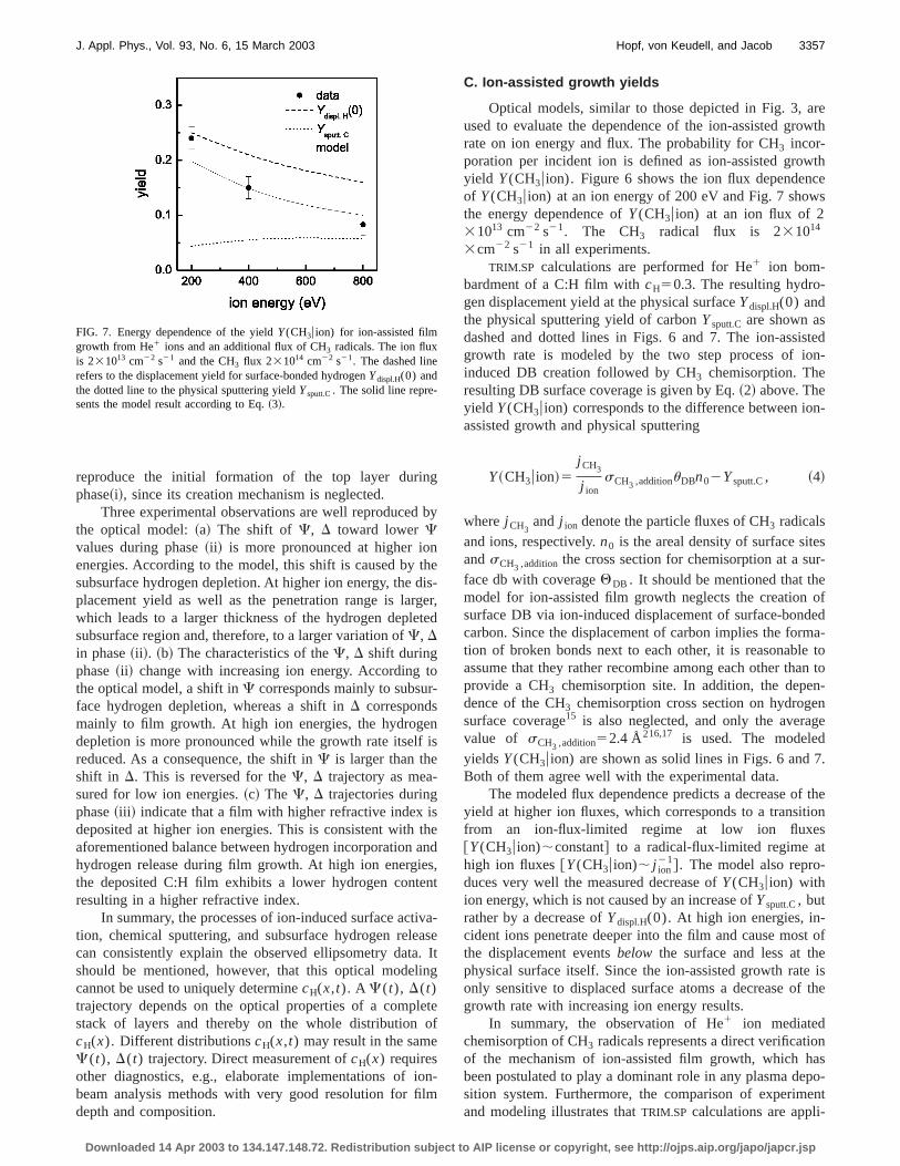
FIG. 7. Energy dependence of the yieldY(CH3u ion) for ion-assisted filmgrowth from He1 ions and an additional flux of CH3 radicals. The ion fluxis 231013 cm22 s21 and the CH3 flux 231014 cm22 s21. The dashed linerefers to the displacement yield for surface-bonded hydrogenYdispl.H(0) andthe dotted line to the physical sputtering yieldYsputt.C. The solid line repre-sents the model result according to Eq.~3!.
Downloaded 14 Apr 2003 to 134.147.148.72. Redistribution subject to A
y
es-r,d
s
end,t
a-seItg
tef
-
C. Ion-assisted growth yields
Optical models, similar to those depicted in Fig. 3, aused to evaluate the dependence of the ion-assisted grrate on ion energy and flux. The probability for CH3 incor-poration per incident ion is defined as ion-assisted groyield Y(CH3u ion). Figure 6 shows the ion flux dependenof Y(CH3u ion) at an ion energy of 200 eV and Fig. 7 showthe energy dependence ofY(CH3u ion) at an ion flux of 231013 cm22 s21. The CH3 radical flux is 231014
3cm22 s21 in all experiments.TRIM.SP calculations are performed for He1 ion bom-
bardment of a C:H film withcH50.3. The resulting hydro-gen displacement yield at the physical surfaceYdispl.H(0) andthe physical sputtering yield of carbonYsputt.C are shown asdashed and dotted lines in Figs. 6 and 7. The ion-assigrowth rate is modeled by the two step process of ioinduced DB creation followed by CH3 chemisorption. Theresulting DB surface coverage is given by Eq.~2! above. Theyield Y(CH3u ion) corresponds to the difference between ioassisted growth and physical sputtering
Y~CH3u ion!5j CH3
j ionsCH3 ,additionuDBn02Ysputt.C, ~4!
wherej CH3and j ion denote the particle fluxes of CH3 radicals
and ions, respectively.n0 is the areal density of surface siteandsCH3 ,addition the cross section for chemisorption at a suface db with coverageQDB . It should be mentioned that thmodel for ion-assisted film growth neglects the creationsurface DB via ion-induced displacement of surface-boncarbon. Since the displacement of carbon implies the formtion of broken bonds next to each other, it is reasonableassume that they rather recombine among each other thaprovide a CH3 chemisorption site. In addition, the depedence of the CH3 chemisorption cross section on hydrogsurface coverage15 is also neglected, and only the averavalue of sCH3 ,addition52.4 Å216,17 is used. The modeledyields Y(CH3u ion) are shown as solid lines in Figs. 6 andBoth of them agree well with the experimental data.
The modeled flux dependence predicts a decrease oyield at higher ion fluxes, which corresponds to a transitfrom an ion-flux-limited regime at low ion fluxes@Y(CH3u ion);constant# to a radical-flux-limited regime ahigh ion fluxes@Y(CH3u ion); j ion
21#. The model also repro-duces very well the measured decrease ofY(CH3u ion) withion energy, which is not caused by an increase ofYsputt.C, butrather by a decrease ofYdispl.H(0). At high ion energies, in-cident ions penetrate deeper into the film and cause mosthe displacement eventsbelow the surface and less at thphysical surface itself. Since the ion-assisted growth ratonly sensitive to displaced surface atoms a decrease ogrowth rate with increasing ion energy results.
In summary, the observation of He1 ion mediatedchemisorption of CH3 radicals represents a direct verificatioof the mechanism of ion-assisted film growth, which hbeen postulated to play a dominant role in any plasma desition system. Furthermore, the comparison of experimand modeling illustrates thatTRIM.SP calculations are appli-
IP license or copyright, see http://ojps.aip.org/japo/japcr.jsp

ali
istn
bicaHne
thenes
pe,
adihehe
alse
ci.
,
Sci.
er
3358 J. Appl. Phys., Vol. 93, No. 6, 15 March 2003 Hopf, von Keudell, and Jacob
cable to describe ion-assisted film formation not only qutatively but also quantitatively very well.
IV. CONCLUSION
Ion-induced surface processes during plasma-assgrowth of C:H films were investigated in a model experimeemploying quantified particle sources for He1 ions and CH3radicals. It was shown that the growth rate is dominatedthe ion-induced creation of dangling bonds at the physsurface, which serve as chemisorption sites for incident C3
radicals. The film properties are dominated by the ioinduced preferential release of hydrogen in the subsurfacthe growing film.
It was shown that model calculations based onTRIM.SP code are able to qualitatively—and to some exteven quantitatively—predict ion-induced film growth ratas well as ion-induced hydrogen release. Hence,TRIM.SP
based models can in principle be used to predict the dedence of properties, such as density and refractive indexion energy and ion mass.
It is, however, important to note that during plasmdeposition of C:H films not only ions and hydrocarbon racals impinge onto a growing film surface. In addition, tabundant flux of atomic hydrogen will certainly influence t
Downloaded 14 Apr 2003 to 134.147.148.72. Redistribution subject to A
-
edt
yl
-of
et
n-on
-
growth process. The mutual influences of different radicand ions during film formation will be the subject of futurresearch.
1A. Grill, Diamond Relat. Mater.8, 428 ~1999!.2T. Schwarz-Selinger, A. von Keudell, and W. Jacob, J. Appl. Phys.86,3988 ~1999!.
3P. Koidl, C. Wild, B. Dischler, J. Wagner, and M. Ramsteiner, Mater. SForum52, 41 ~1989!.
4P. Koidl, C. Wild, R. Locher, and R. E. Sah,Diamond and Diamond-likeFilms and CoatingsNATO-ASI Series B: Physics Vol. 266~Plenum, NewYork, 1991!, p. 243.
5W. Jacob, Thin Solid Films326, 1 ~1998!.6W. Moller, Thin Solid Films228, 319 ~1993!.7W. Moller and B. M. U. Scherzer, J. Appl. Phys.64, 4860~1988!.8C. Garcia-Rosales, W. Eckstein, and J. Roth, J. Nucl. Mater.218, 8 ~1994!.9C. Hopf and A. von Keudell~unpublished!.
10C. Hopf, A. von Keudell, and W. Jacob, Nucl. Fusion42, L27 ~2002!.11W. Eckstein,Computer Simulation of Ion Solid Interactions, Springer Se-
ries in Materials Science, 1st ed.~Springer, Berlin, 1991!.12B. T. Kelly, Physics of Graphite, 1st ed.~Applied Science Publishers
London, 1981!.13T. Schwarz-Selinger, V. Dose, W. Jacob, and A. von Keudell, J. Vac.
Technol. A19, 101 ~2001!.14W. Jacob, C. Hopf, A. von Keudell, M. Meier, and T. Schwarz-Seling
~unpublished!.15M. Meier, R. Preuss, and V. Dose~unpublished!.16A. von Keudell, Thin Solid Films402, 1 ~2002!.17M. Meier and A. von Keudell, J. Appl. Phys.90, 3585~2001!.
IP license or copyright, see http://ojps.aip.org/japo/japcr.jsp