devb bim harmonisation guidelines for wds
TRANSCRIPT
BIM HARMONISATION GUIDELINES FOR WORKS DEPARTMENTS
Version: 1.0
October 2021
© The Government of the Hong Kong Special Administrative Region
The contents of this document remain the property of and may not be reproduced in whole or in part without the express permission of the Government of the HKSAR
P1
BIM HARMONISATION GUIDELINES FOR WORKS DEPARTMENTS DISTRIBUTION & RELEASE
i-1
Distribution
Copy No. Holder
1 Development Bureau (DEVB)
2 Architectural Services Department
3 Civil Engineering and Development Department
4 Drainage Services Department
5 Electrical and Mechanical Services Department
6 Highways Department
7 Water Supplies Department
8 Lands Department
Prepared By: Secretary
DEVB BIM Working Group, DEVB(WB)
Date: 15.10.2021
P2
BIM HARMONISATION GUIDELINES FOR WORKS DEPARTMENTS TABLE OF CONTENTS
iii-1
Amendment History
Change Number
Revision Description Pages Affected on Respective Version
Revision / Version Number Date
1 1st Draft
Initial draft derived from the CEDD BIM Harmonisation Guidelines for Works Departments
0.1 21.5.2021
2 2nd Draft Draft Guide sent to WDs for comment 0.2 11.8.2021
3 3rd Draft Revised Guide to WDs for further comment 0.3 30.9.2021
4 Endorsed No material change since v0.3. Endorsed by DEVB BIM WG 1.0 15.10.2021
P3
BIM HARMONISATION GUIDELINES FOR WORKS DEPARTMENTS TABLE OF CONTENTS
iii-2
TABLE OF CONTENTS
1. Introduction .......................................................................................................................................... 1 1.1. Background ............................................................................................................................................ 1 1.2. Objectives ............................................................................................................................................... 1 1.3. Harmonisation Approach ....................................................................................................................... 2
2. Information Requirements and Exchange ......................................................................................... 3 2.1. Information Ownership .......................................................................................................................... 3 2.2. IT Environment ...................................................................................................................................... 3 2.3. BIM File Size ......................................................................................................................................... 4 2.4. Level of Information Need (LOIN) Gap Analysis ................................................................................. 4 2.5. Information Exchange Formats and Mechanism .................................................................................... 6 2.6. Data Security Classification ................................................................................................................... 7
3. BIM Object ........................................................................................................................................... 8 3.1. Principles ................................................................................................................................................ 8 3.2. CIC BIM Object Guide and Portal ......................................................................................................... 8 3.3. Process of Adopting CIC BIM Objects ................................................................................................ 10 3.4. Naming of BIM Objects ....................................................................................................................... 11 3.5. Guidelines for BIM Object Authoring ................................................................................................. 14 3.6. BIM Object Management ..................................................................................................................... 16 3.7. Workflow for Sharing BIM Object ...................................................................................................... 17
4. Federation and BIM Model Naming ................................................................................................. 19 4.1. BIM Model Naming Principle .............................................................................................................. 19 4.2. Information Container Identification Fields ......................................................................................... 20 4.3. Federation Strategy .............................................................................................................................. 26 4.4. BIM Model Naming ............................................................................................................................. 27 4.5. Naming of Drawings Generated from BIM model ............................................................................... 27
5. LOIN Implementation ....................................................................................................................... 28 5.1. Aligned BIM Standards ........................................................................................................................ 28 5.2. BEP ...................................................................................................................................................... 28 5.3. BIM Modelling Setting ........................................................................................................................ 28 5.4. LOD-G ................................................................................................................................................. 29 5.5. LOD-I ................................................................................................................................................... 31 5.6. Appearance ........................................................................................................................................... 31
6. The Way Forward .............................................................................................................................. 33 6.1. Regular Review and Update ................................................................................................................. 33 6.2. Codification Management .................................................................................................................... 33 6.3. Project Close-out Protocols .................................................................................................................. 33 6.4. BIM / GIS Integration .......................................................................................................................... 34 6.5. Departmental Transition ....................................................................................................................... 34 6.6. Information Management ..................................................................................................................... 34
P4
BIM HARMONISATION GUIDELINES FOR WORKS DEPARTMENTS TABLE OF CONTENTS
iii-3
List of Tables Table 3-1 Descriptions and Guidelines for the BIM Object Naming Fields ......................................................... 12 Table 3-2 Folder Structure of BIM Object Library............................................................................................... 17 Table 4-1 Information Container ID Fields .......................................................................................................... 23 Table 5-1 LOD-G Definition ................................................................................................................................ 29 Table 5-2 Colour Appearance by Discipline for Underground Utilities ............................................................... 32 Table 5-3 Colour Appearance by Discipline for Above-grade ............................................................................. 32
List of Figures Figure 3-1 CIC BIM Portal ..................................................................................................................................... 9 Figure 3-2 BIM Object Sheet ................................................................................................................................. 9 Figure 3-3 An Example of BIM object found on CIC BIM Portal ....................................................................... 10 Figure 3-4 BIM Object Adoption Scenarios ......................................................................................................... 11 Figure 3-5 Sample Simplified BIM Object based on Detailed BIM Object ......................................................... 15 Figure 3-6 Sample Lamp Post BIM Object Division ............................................................................................ 16 Figure 4-1 Information Container ID Fields - UK Annex vs Naming of this Guide ............................................ 21
P5
BIM HARMONISATION GUIDELINES FOR WORKS DEPARTMENTS TABLE OF CONTENTS
iii-4
List of Appendices
Appendix I – ISO 19650 TerminologiesAppendix II – Information Responsibility Assignment MatrixAppendix III – Data Filtering Rule TableAppendix IV – Master Type List
(The List contains with FLIP, CEDD, DSD and HyD’s codes. Due to the list is huge, it will be sent by CD-ROM with the hard copy of the Guide.)
Appendix V – Examples of BIM Object Authoring and Importing Civil 3D BIM Objects intoBIM Models
Appendix VI – LOD-I Requirements, Creation and ExtractionAppendix VII – Sample BIM Object Check FormAppendix VIII – Federation Strategy Diagrams and Naming ExamplesAppendix IX – Sample Project-Specific Codes for NamingAppendix X – Common Codes for NamingAppendix XI – Sample Spreadsheet for BIM File Name ValidationAppendix XII – Mapping Table for Information Container ID Fields – ArchSDAppendix XIII – Mapping Table for Information Container ID Fields – CEDD GEOAppendix XIV – Mapping Table for Information Container ID Fields – DSDAppendix XV – Mapping Table for Information Container ID Fields – EMSDAppendix XVI – Mapping Table for Information Container ID Fields – HyDAppendix XVII – Mapping Table for Information Container ID Fields – WSD Appendix XVIII – Sample Project Close-out Checklist
P6
BIM HARMONISATION GUIDELINES FOR WORKS DEPARTMENTS ABBREVIATION
iv-1
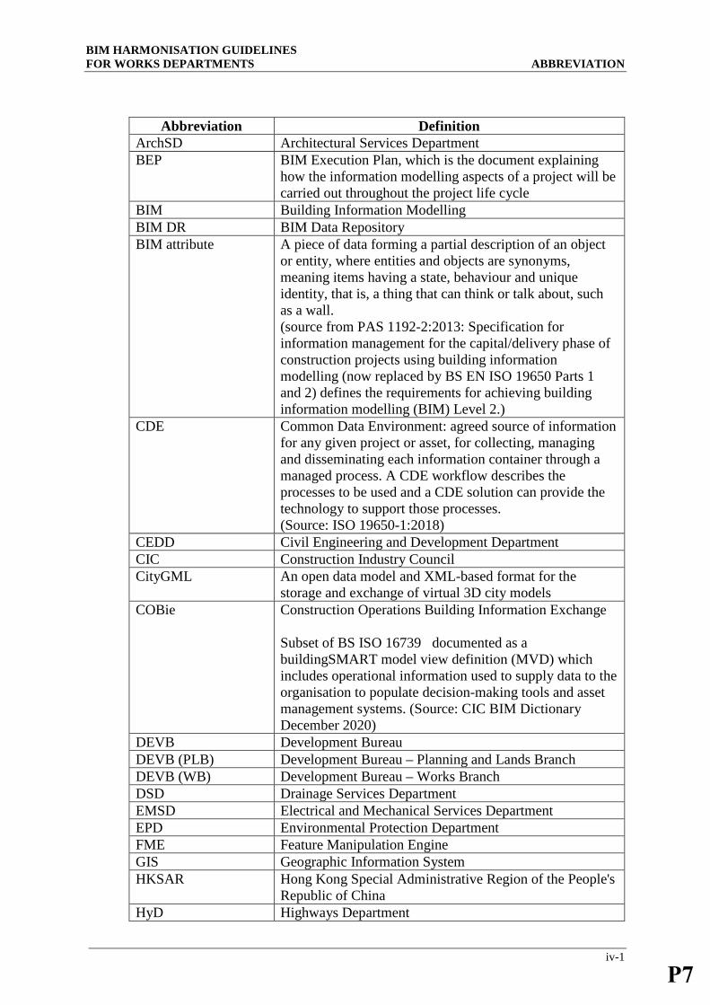
Abbreviation Definition ArchSD Architectural Services Department BEP BIM Execution Plan, which is the document explaining
how the information modelling aspects of a project will be carried out throughout the project life cycle
BIM Building Information Modelling BIM DR BIM Data Repository BIM attribute A piece of data forming a partial description of an object
or entity, where entities and objects are synonyms, meaning items having a state, behaviour and unique identity, that is, a thing that can think or talk about, such as a wall. (source from PAS 1192-2:2013: Specification for information management for the capital/delivery phase of construction projects using building information modelling (now replaced by BS EN ISO 19650 Parts 1 and 2) defines the requirements for achieving building information modelling (BIM) Level 2.)
CDE Common Data Environment: agreed source of information for any given project or asset, for collecting, managing and disseminating each information container through a managed process. A CDE workflow describes the processes to be used and a CDE solution can provide the technology to support those processes. (Source: ISO 19650-1:2018)
CEDD Civil Engineering and Development Department CIC Construction Industry Council CityGML An open data model and XML-based format for the
storage and exchange of virtual 3D city models COBie Construction Operations Building Information Exchange
Subset of BS ISO 16739 documented as a buildingSMART model view definition (MVD) which includes operational information used to supply data to the organisation to populate decision-making tools and asset management systems. (Source: CIC BIM Dictionary December 2020)
DEVB Development Bureau DEVB (PLB) Development Bureau – Planning and Lands Branch DEVB (WB) Development Bureau – Works Branch DSD Drainage Services Department EMSD Electrical and Mechanical Services Department EPD Environmental Protection Department FME Feature Manipulation Engine GIS Geographic Information System HKSAR Hong Kong Special Administrative Region of the People's
Republic of China HyD Highways Department
P7
BIM HARMONISATION GUIDELINES FOR WORKS DEPARTMENTS ABBREVIATION
iv-2
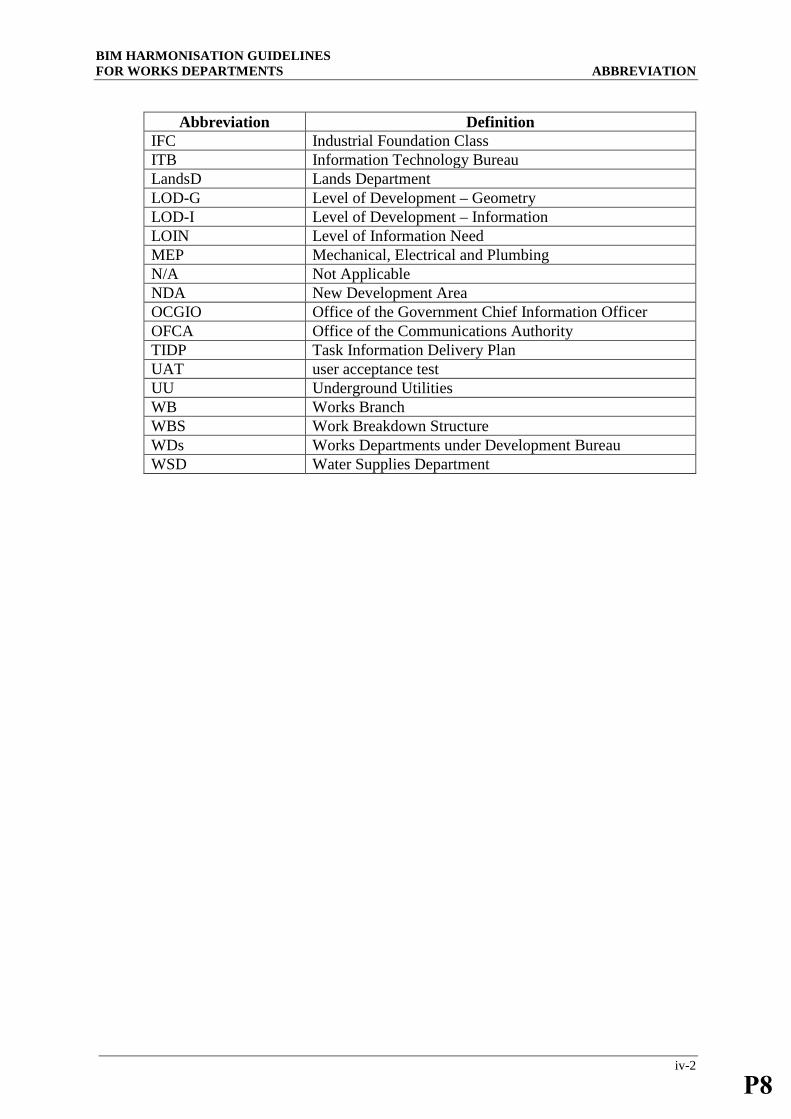
Abbreviation Definition IFC Industrial Foundation Class ITB Information Technology Bureau LandsD Lands Department LOD-G Level of Development – Geometry LOD-I Level of Development – Information LOIN Level of Information Need MEP Mechanical, Electrical and Plumbing N/A Not Applicable NDA New Development Area OCGIO Office of the Government Chief Information Officer OFCA Office of the Communications Authority TIDP Task Information Delivery Plan UAT user acceptance test UU Underground Utilities WB Works Branch WBS Work Breakdown Structure WDs Works Departments under Development Bureau WSD Water Supplies Department
P8
BIM HARMONISATION GUIDELINES FOR WORKS DEPARTMENTS ABBREVIATION
iv-3
Foreword The Development Bureau (DEVB) is pleased to announce the publication of DEVB BIM Harmonisation Guidelines for Work Departments (the Guideline) with the goal to align BIM implementation, delivery and management for capital works projects. Using this Guideline for information exchange between Works Departments (WDs) and Lands Department (LandsD), it would support the Smart City planning. The industry would also benefit from the use of BIM, GIS and 3D data for more efficient design, construction, operation and asset management workflows in the project lifecycle. At the onset of this harmonisation initiative, a consultancy study (the Study) on BIM Harmonisation for BIM/GIS Integration under First Phase Development of KTN and FLN NDA was commissioned by the Civil Engineering and Development Department (CEDD). As one of the key deliverables, it formulated a BIM Harmonisation Guidelines for WDs for the assets under the study. This harmonisation initiative was then taken further to cover capital works projects outside the scope of the study. With concerted efforts of the WDs and LandsD, this Guideline is formulated. This Guideline shall be adhered to for upcoming BIM adopting capital works projects to ensure consistency when authoring, reviewing and managing BIM files, BIM models and BIM objects. The adoption of the Guideline would facilitate the sharing and maintenance of BIM models and information exchange among WDs and LandsD. The Guideline is to be reviewed regularly under the DEVB BIM Working Group so as to upkeep with technological advancements and industry developments. DEVB would like to thank everyone who has contributed to the success of the Publication, in particular the Project Steering Group and Project Working Group members of the Study:
• Architectural Services Department • Civil Engineering and Development Department • Construction Industry Council • Development Bureau – Planning and Lands Branch • Development Bureau – Works Branch • Drainage Services Department • Electrical and Mechanical Services Department • Highways Department • Lands Department • Water Supplies Department
Finally, contributions and efforts given by the consultant of the Study, AECOM Asia Company Limited, is also highly appreciated.
P9
BIM HARMONISATION GUIDELINES FOR WORKS DEPARTMENTS EXECUTIVE SUMMARY
1
1. Introduction
1.1. Background
1.1.1. CEDD commissioned a consultancy to carry out a BIM horizontal harmonisation study for the First Phase Development of KTN and FLN NDA (the Study) and produced a BIM Harmonisation Guidelines. The said guidelines encompass standards governing the design BIM models, construction BIM models and shareable BIM models enabling BIM/GIS integration to facilitate LandsD’s continuous study and production of the 3D digital maps for Hong Kong. Under the Study, a BIM Data Repository (BIM DR) will be established to store the BIM models of the First Phase Development of KTN and FLN NDA for effective and efficient information exchange among Works Departments (WDs) and LandsD.
1.1.2. Subsequent to the endorsement of the BIM Harmonisation Guidelines of the Study, DEVB took the opportunity to expand and generalise the document and formulate the DEVB BIM Harmonisation Guidelines for WDs (this document) to use for projects outside the First Phase Development of KTN and FLN NDA. WDs shall adopt the harmonisation standards outlined in the DEVB BIM Harmonisation Guidelines for WDs (this document, thereafter referred to as the Guide) in the upcoming capital works projects adopting BIM.
1.1.3. The harmonization components of this Guide include: a) Information requirements and exchange (Section 2)b) BIM object (Section 3)c) Federation and BIM model naming (Section 4)d) LOIN implementation (Section 5)
1.1.4. The integrated platform (BIM DR) and conversion engine have been documented separately in other submissions of the Study of CEDD.
1.1.5. This Guide addresses the standardisation of the digital models comprising BIM models, objects, and attributes: a) BIM Models, which include native and shareable models;b) BIM Objects, which are parametric elements used to author BIM models. They
are usually resided on the CIC BIM Portal or authored in accordance withprinciples of this Guide; and
c) BIM Attributes, which could facilitate BIM model and object management.
1.2. Objectives
1.2.1. The objectives of this Guide are: a) To enable sharing, dissemination and maintenance of BIM models and BIM
attributes across the WDs and LandsD;b) To support sharing of BIM objects with CIC;
P10
BIM HARMONISATION GUIDELINES FOR WORKS DEPARTMENTS EXECUTIVE SUMMARY
2
c) To form the standards to support LandsD’s BIM Data Repository, 3D digitalmap initiatives, and the forthcoming 3D Land Information System;
d) To provide aligned BIM standards horizontally across WDs for adoption in theirupcoming projects with emphasis on consistent modelling approaches.
1.3. Harmonisation Approach
1.3.1. This harmonisation exercise makes reference to the following documents: a) The BIM Harmonization Guidelines for the First Phase Development of KTN
and FLN NDA of the CEDD;b) Parts 1 and 2 (2018 version) of BS EN ISO 19650 (ISO 19650): to adopt a
common approach for collaborative production of information and informationexchange requirements;
c) ISO 19650 terminologies (refer to Appendix I);d) WDs’ current BIM development, standards, documents, practice notes,
guidelines, regulations and legislations, including data owners’ graphical andnon-graphical information (geometrical and non‑geometrical information inISO 19650 terms) requirements;
e) DEVB’s Technical Circular (Works) No. 12/2020 – Adopting of BuildingInformation Modelling for Capital Works Projects in Hong Kong;
f) CIC BIM Standards - General: December 2020 Edition, andg) CIC Production of BIM Object Guide - General Requirements (August 2019)
1.3.2. The following key harmonisation focuses will be addressed in details in the coming sections of this Guide: a) Naming Convention: BIM file naming (information container identification as
in National Annex NA.2 of BS EN ISO 19650-2:2018) for BIM models andBIM objects and their abbreviations are inconsistent;
b) Information Storage and Sharing: There are varying model division strategiesamongst WDs;
c) Project Information Requirements: There are varying information demandsbetween WDs and LandsD, and smooth access of information may be limitedby hardware and software capability (IT environment); and
d) Project Delivery: Some WDs do not have project closeout protocols.
P11
BIM HARMONISATION GUIDELINES FOR WORKS DEPARTMENTS INFORMATION REQUIREMENTS AND EXCHANGE
3
2. Information Requirements and Exchange
2.1. Information Ownership
2.1.1. Information ownership shall be defined at onset of a project.
2.1.2. As soon as the asset owner is identified, asset owner-specific requirements, including departmental BIM documents, should be followed. If asset owner could not be identified, the BIM Execution Plan (BEP) should be followed, prior to adopting the CIC BIM Standards (the latest version). The practices should be properly documented in the BEP.
2.1.3. WDs should adhere to this Guide when preparing the BIM models (in native and open format) and objects for sharing with others.
2.1.4. WDs share the design BIM model (after tender stage) and as-built model (after construction) as the input files for necessary conversion of BIM models as per stipulated in paragraph 19 of the Technical Circular (Works) No. 12/2020. The circular will be updated from time to time.
2.1.5. WDs are suggested to review the BIM models to confirm whether such information could be shared.
2.1.6. To facilitate information exchange, a BIM DR has been established under the Study of CEDD which will be handed over to LandsD. The BIM DR serves to host native BIM models (developed in accordance with this Guide), shareable BIM models (IFC) and 3D GIS Open Format (CityGML).
2.2. IT Environment
Hardware, software and internet speed should meet minimum operability requirements to optimize interdepartmental information exchange.
2.2.1. Hardware
2.2.1.1. Not applicable.
2.2.2. Software
2.2.2.1. A single, common or interoperable BIM modelling software that is able to generate open format files should be used for a project (composing of several contracts) as far as practicable. This is to enable seamless flow and sharing of information within the project.
2.2.2.2. When selecting software, project information requirements and support of open format such as IFC should be considered.
2.2.2.3. Segregation of BIM models and software for modelling should be practised to balance modelling efficiency, drawing generation needs and non-geometrical
P12
BIM HARMONISATION GUIDELINES FOR WORKS DEPARTMENTS INFORMATION REQUIREMENTS AND EXCHANGE
4
information interoperability. For example, the following principles could be adopted for design stage: a) Stormwater drainage and sewerage were demarcated at the agreed connection
point between building drainage and civil drainage. b) Water supply, electrical power supply, gas supply, telecommunications were
demarcated at the agreed interface point between building works and civil works.
2.2.2.4. For preparation of the BIM models, project officers should consult the departmental BIM Support Team on the recommended software and software version for model development.
2.2.2.5. For the shareable BIM format, IFC v4 will be used.
2.2.3. Internet Speed
2.2.3.1. Limitation in internet speed could adversely affect the access to BIM DR and reduce smoothness in viewing 3D models. Therefore, adequate internet speed is essential for effective information exchange.
2.3. BIM File Size
2.3.1. For WDs without departmental BIM model file size limits, it is recommended that the maximum file size for each BIM model should be capped at 500MB. This size limit is suggested to be adopted in departmental standards. Due to varying project sizes and requirements, this Guide does not provide limit or standard to the total project file size. WDs should avoid, as far as practicable, large file sizes which would require substantial amount of storage, thereby unnecessarily increasing the time and cost to establish and operate the BIM DR.
2.3.2. To help control the BIM model file size, the maximum size of each BIM object file used should be kept at the minimum, preferably under 5MB.
2.4. Level of Information Need (LOIN) Gap Analysis
2.4.1. In accordance with the principles of ISO 19650, information is required for performing a task or supporting a decision. The LOIN is defined as the appropriate level (or “richness”) of information to be provided for each information exchange, avoiding risk (too little information) or waste (too much information). LOIN could either be expressed in the richness of geometric details (LOD-G) or richness of datasets (LOD-I).
2.4.2. LOIN stems from the fundamental information requirement, which is a description of the extent and detail of information exchange in terms of geometry, information and documentation. Specifically, when collaborating within project participants, information approved for sharing includes: a) The lead appointed party’s information requirements; b) The level of information need; and
P13
BIM HARMONISATION GUIDELINES FOR WORKS DEPARTMENTS INFORMATION REQUIREMENTS AND EXCHANGE
5
c) Information needed for coordination by other task teams.
2.4.3. A comparison was conducted for LOIN and LOD-I/LOD-G in CIC BIM Standards - General: December 2020 Edition as adopted by most of the WDs. The results could be summarised in the following three scenarios: a) LOIN and LOD-I/LOD-G have aligned concepts as described in Section 2.4.4; b) LOIN and LOD-I/LOD-G have aligned concepts and WDs have basic
awareness, but requiring further clarification to enhance the awareness, as described in Section 2.4.5; and
c) There are gaps between LOIN and LOD-I/LOD-G, and suggested actions are provided in Section 2.4.6.
2.4.4. Concepts that are aligned between LOIN and CIC’s LOD-I and LOD-G include: a) Each BIM model element has an object ID; b) Each BIM model element has an object name; c) Each BIM model element has an object definition; d) Each BIM model element has an object description; e) Each BIM model element has a LOD-G which includes detail, dimensionality,
location, appearance, and parametric behaviour; f) Each BIM model element has a LOD-I which includes identification of
properties and information content properties; and g) Documentation requirements which includes identification of documentation
and format e.g. IFC, PDF, DWG, XML, etc. are necessary.
2.4.5. Concepts that are aligned between LOIN and CIC’s LOD-I and LOD-G but requiring more awareness include: a) Information delivery milestones could be specified to clarify when the
information is needed, with an emphasis on lifecycle and asset management requirements.
b) BIM model elements within a federation structure (information container breakdown structure as defined in ISO 19650) could be identified by function, spatial arrangement and geometrical composition. For example, WDs are suggested to add “spatial requirements” to rooms, spaces, corridors, plants and equipment rooms to define how they interact spatially, by means of geometrical (e.g. dynamic envelopes for clearance or tolerance) or non-geometrical (e.g. parametric attribute fields containing length, area, volume requirements, etc.). The spatial requirements for civil and infrastructural disciplines should also be considered.
c) In view of the aforementioned spatial composition and requirements, WDs are suggested to utilise federation strategies and naming to facilitate work breakdown structure (WBS).
2.4.6. Identified gaps between LOIN and CIC’s LOD-I and LOD-G include: a) LOIN identifies the BIM model’s purposes for information delivery, while
LOD identifies the development maturity of elements. LOD-I and LOD-G can
P14
BIM HARMONISATION GUIDELINES FOR WORKS DEPARTMENTS INFORMATION REQUIREMENTS AND EXCHANGE
6
differ for elements in the same stage. WDs are suggested to utilise information container identification (ID) to specify the purpose of BIM models.
b) Stakeholders who require and deliver the information shall be identified. Stakeholders are suggested to adopt the concept of RACI (ISO 19650-2:2018 Annex A’s information management assignment matrix) and describes in BEP. The acronyms of RACI are defined as followed: R - Responsible for undertaking activity A - Accountable for activity completion C - Consulted during activity I - Informed following activity completion
Appendix II – Information Responsibility Assignment Matrix for details.
2.4.7. Way Forward of LOIN Implementation LOIN aims to strengthen LOD-G and LOD-I on the basis of CIC BIM Standards - General: December 2020 Edition. Refer to Section 5 for details.
2.5. Information Exchange Formats and Mechanism
2.5.1. To facilitate the data exchange and extraction needs of WDs, a clear set of criteria should be established. The sharing of commonly used BIM data across WDs in a self-service manner via a centrally managed BIM DR is efficient with fast turnaround time. It facilitates site selection, site analysis, planning of location of services with a view to achieve design quality and efficiency, and minimise risks of clashes and time for reworks. Understanding the demands from WDs LandsD give rise to the subsequent design of the conversion engine and the shareable BIM.
2.5.2. Appendix III – Data Filtering Rule Table shows the data required from specific departments. LandsD prefers having a full set of BIM models in native format, while other WDs have certain department-specific data extraction rules.
2.5.3. To enable interoperability, open formats, such as IFC, shall be adopted to facilitate geometrical and non-geometrical information exchange. Geometrical information exchange aims to export BIM models to open BIM formats. Non-geometrical information exchange aims to export BIM attributes to tabular format such as COBie (Construction Operations Building Information Exchange). COBie is an international standard for data exchange, and it is the most commonly used standard for data handover from construction to operations. Through a conversion engine, the open format CityGML will be made available and stored in the BIM DR.
2.5.4. Information exchange mechanism relies on the followings: a) Information container ID, which entails consistent ID field definitions and
abbreviation codes to facilitate file-based data filtering; b) Data filtering rules, which outlines the key criteria for data exchange and
extraction; and c) WDs’ BIM files, which shall be in compliance with the defined naming
convention of this Guide.
P15
BIM HARMONISATION GUIDELINES FOR WORKS DEPARTMENTS INFORMATION REQUIREMENTS AND EXCHANGE
7
2.6. Data Security Classification
2.6.1. Data security considerations include user access level and data classification.
2.6.2. Upon the establishment of BIM DR, WDs’ users would be allowed to access the BIM DR based on WDs’ information needs. Departmental users are assigned with appropriate access rights. No restricted, sensitive or confidential data should be shared.
2.6.3. Standardised data classification could further ensure security in the data exchange process in the future. Refer to Section 6.6.4 for details.
P16
BIM HARMONISATION GUIDELINES FOR WORKS DEPARTMENTS BIM OBJECT
8
3. BIM Object
3.1. Principles
3.1.1. The principles of authoring BIM objects should follow CIC BIM Object Guide, which contains LOD-G (geometrical) and LOD-I (non-geometrical) requirements. In addition, Appendix V and Appendix VI provide further examples for handling BIM objects’ LOD-G and LOD-I.
3.1.2. CIC BIM Portal has provided an industry-wide, centralised and publicly accessible platform for sharing of BIM objects. BIM objects authored by the WDs or from capital works projects should be incorporated into the CIC BIM Portal upon certification by CIC. WDs should follow Section 3.7 to provide BIM objects to CIC. WDs should notify project awardees to utilise BIM objects shared at CIC BIM Portal as far as practicable and make reference to WDs’ BIM objects that have been internally certified for use.
3.1.3. BIM objects’ naming convention should follow Section 3.4, which is derived from CIC BIM Object Guide’s principles and further developed.
3.1.4. To minimise information loss during conversion, the appropriate category type for the BIM objects should be defined. The use of generic model for BIM object authoring should be minimised as far as practicable.
3.1.5. To optimise information management within BIM models, replicable BIM objects (e.g. windows, doors, signage, fittings) should be used to compose BIM models as far as practicable.
3.2. CIC BIM Object Guide and Portal
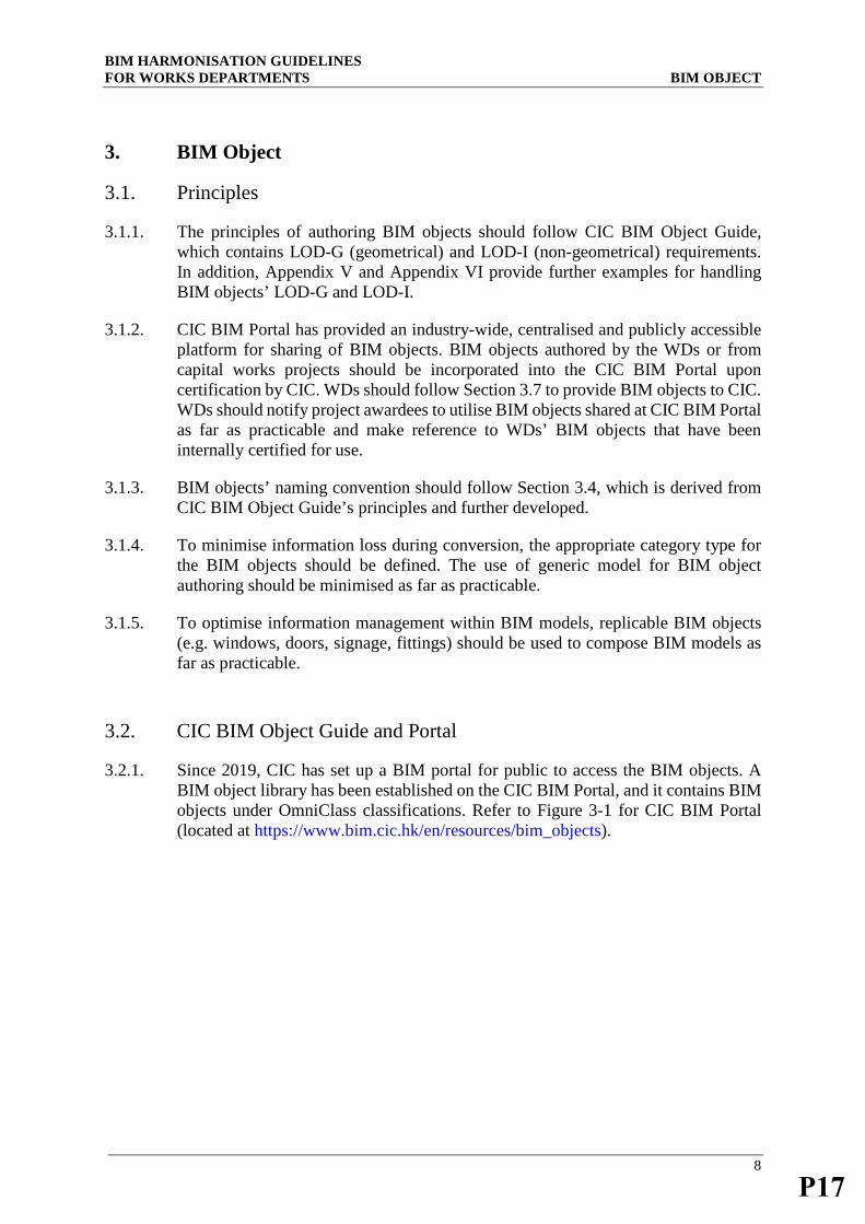
3.2.1. Since 2019, CIC has set up a BIM portal for public to access the BIM objects. A BIM object library has been established on the CIC BIM Portal, and it contains BIM objects under OmniClass classifications. Refer to Figure 3-1 for CIC BIM Portal (located at https://www.bim.cic.hk/en/resources/bim_objects).
P17
BIM HARMONISATION GUIDELINES FOR WORKS DEPARTMENTS BIM OBJECT
9
Figure 3-1 CIC BIM Portal
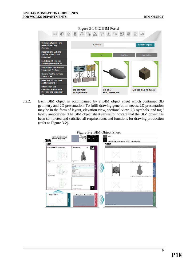
3.2.2. Each BIM object is accompanied by a BIM object sheet which contained 3D geometry and 2D presentation. To fulfil drawing generation needs, 2D presentation may be in the form of layout, elevation view, sectional view, 2D symbols, and tag / label / annotations. The BIM object sheet serves to indicate that the BIM object has been completed and satisfied all requirements and functions for drawing production (refer to Figure 3-2).
Figure 3-2 BIM Object Sheet
P18
BIM HARMONISATION GUIDELINES FOR WORKS DEPARTMENTS BIM OBJECT
10
3.3. Process of Adopting CIC BIM Objects
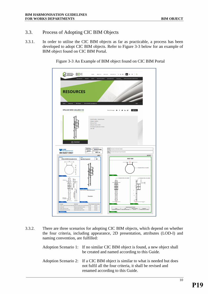
3.3.1. In order to utilise the CIC BIM objects as far as practicable, a process has been developed to adopt CIC BIM objects. Refer to Figure 3-3 below for an example of BIM object found on CIC BIM Portal.
Figure 3-3 An Example of BIM object found on CIC BIM Portal
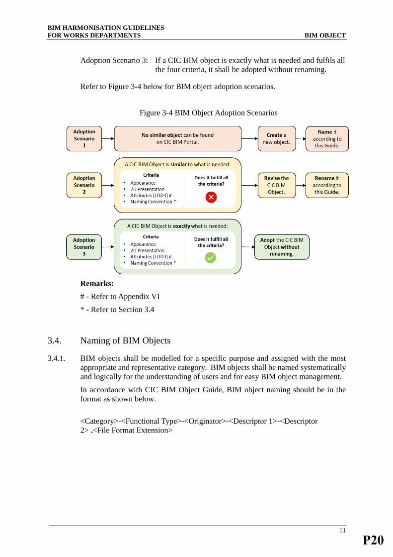
3.3.2. There are three scenarios for adopting CIC BIM objects, which depend on whether the four criteria, including appearance, 2D presentation, attributes (LOD-I) and naming convention, are fulfilled:
Adoption Scenario 1: If no similar CIC BIM object is found, a new object shall be created and named according to this Guide.
Adoption Scenario 2: If a CIC BIM object is similar to what is needed but does not fulfil all the four criteria, it shall be revised and renamed according to this Guide.
P19
BIM HARMONISATION GUIDELINES FOR WORKS DEPARTMENTS BIM OBJECT
11
Adoption Scenario 3: If a CIC BIM object is exactly what is needed and fulfils all the four criteria, it shall be adopted without renaming.
Refer to Figure 3-4 below for BIM object adoption scenarios.
Figure 3-4 BIM Object Adoption Scenarios
Remarks: # - Refer to Appendix VI * - Refer to Section 3.4
3.4. Naming of BIM Objects
3.4.1. BIM objects shall be modelled for a specific purpose and assigned with the most appropriate and representative category. BIM objects shall be named systematically and logically for the understanding of users and for easy BIM object management. In accordance with CIC BIM Object Guide, BIM object naming should be in the format as shown below.
<Category>-<Functional Type>-<Originator>-<Descriptor 1>-<Descriptor 2> .<File Format Extension>
P20
BIM HARMONISATION GUIDELINES FOR WORKS DEPARTMENTS BIM OBJECT
12
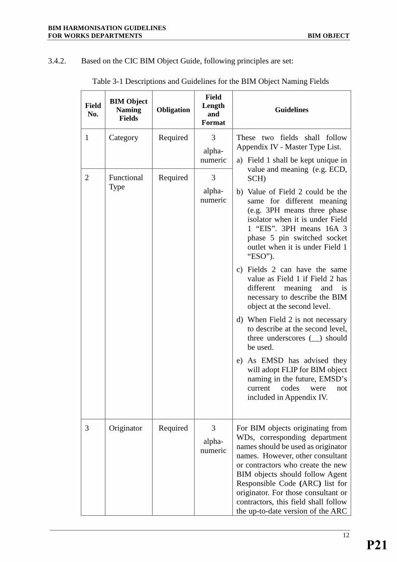
3.4.2. Based on the CIC BIM Object Guide, following principles are set:
Table 3-1 Descriptions and Guidelines for the BIM Object Naming Fields
Field No.
BIM Object Naming Fields
Obligation
Field Length
and Format
Guidelines
1 Category Required
3 alpha-
numeric
These two fields shall follow Appendix IV - Master Type List. a) Field 1 shall be kept unique in
value and meaning (e.g. ECD, SCH)
b) Value of Field 2 could be the same for different meaning (e.g. 3PH means three phase isolator when it is under Field 1 “EIS”. 3PH means 16A 3 phase 5 pin switched socket outlet when it is under Field 1 “ESO”).
c) Fields 2 can have the same value as Field 1 if Field 2 has different meaning and is necessary to describe the BIM object at the second level.
d) When Field 2 is not necessary to describe at the second level, three underscores (__) should be used.
e) As EMSD has advised they will adopt FLIP for BIM object naming in the future, EMSD’s current codes were not included in Appendix IV.
2 Functional Type
Required 3 alpha-
numeric
3 Originator Required 3 alpha-
numeric
For BIM objects originating from WDs, corresponding department names should be used as originator names. However, other consultant or contractors who create the new BIM objects should follow Agent Responsible Code (ARC) list for originator. For those consultant or contractors, this field shall follow the up-to-date version of the ARC
P21
BIM HARMONISATION GUIDELINES FOR WORKS DEPARTMENTS BIM OBJECT
13
Field No.
BIM Object Naming Fields
Obligation
Field Length
and Format
Guidelines
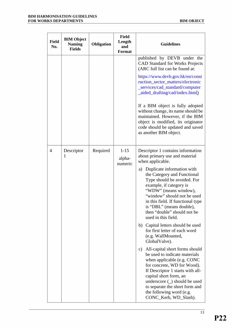
published by DEVB under the CAD Standard for Works Projects (ARC full list can be found at: https://www.devb.gov.hk/en/construction_sector_matters/electronic_services/cad_standard/computer_aided_drafting/cad/index.html) If a BIM object is fully adopted without change, its name should be maintained. However, if the BIM object is modified, its originator code should be updated and saved as another BIM object.
4 Descriptor 1
Required 1-15 alpha-
numeric
Descriptor 1 contains information about primary use and material when applicable. a) Duplicate information with
the Category and Functional Type should be avoided. For example, if category is “WDW” (means window), “window” should not be used in this field. If functional type is “DBL” (means double), then “double” should not be used in this field.
b) Capital letters should be used for first letter of each word (e.g. WallMounted, GlobalValve).
c) All-capital short forms should be used to indicate materials when applicable (e.g. CONC for concrete, WD for Wood). If Descriptor 1 starts with all-capital short form, an underscore (_) should be used to separate the short form and the following word (e.g. CONC_Kerb, WD_Slash).
P22
BIM HARMONISATION GUIDELINES FOR WORKS DEPARTMENTS BIM OBJECT
14
Field No.
BIM Object Naming Fields
Obligation
Field Length
and Format
Guidelines
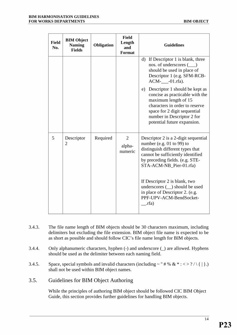
d) If Descriptor 1 is blank, three nos. of underscores (___) should be used in place of Descriptor 1 (e.g. SFM-RCB-ACM-___-01.rfa).
e) Descriptor 1 should be kept as concise as practicable with the maximum length of 15 characters in order to reserve space for 2 digit sequential number in Descriptor 2 for potential future expansion.
5 Descriptor 2
Required 2 alpha-
numeric
Descriptor 2 is a 2-digit sequential number (e.g. 01 to 99) to distinguish different types that cannot be sufficiently identified by preceding fields. (e.g. STE-STA-ACM-NB_Pier-01.rfa) If Descriptor 2 is blank, two underscores (__) should be used in place of Descriptor 2. (e.g. PPF-UPV-ACM-BendSocket-__.rfa)
3.4.3. The file name length of BIM objects should be 30 characters maximum, including delimiters but excluding the file extension. BIM object file name is expected to be as short as possible and should follow CIC’s file name length for BIM objects.
3.4.4. Only alphanumeric characters, hyphen (-) and underscore (_) are allowed. Hyphens should be used as the delimiter between each naming field.
3.4.5. Space, special symbols and invalid characters (including ~ " # % & * : < > ? / \ { | }.) shall not be used within BIM object names.
3.5. Guidelines for BIM Object Authoring
While the principles of authoring BIM object should be followed CIC BIM Object Guide, this section provides further guidelines for handling BIM objects.
P23
BIM HARMONISATION GUIDELINES FOR WORKS DEPARTMENTS BIM OBJECT
15
3.5.1. Simplifying and Enhancing BIM Objects Before using a BIM object, BIM authors should check if it could be simplified or enhanced to meet the project requirements. The basic principle when conducting the modelling works using the BIM objects should be as follows: a) At the same LOD-G, utilising the same BIM object without change as far as
practicable.
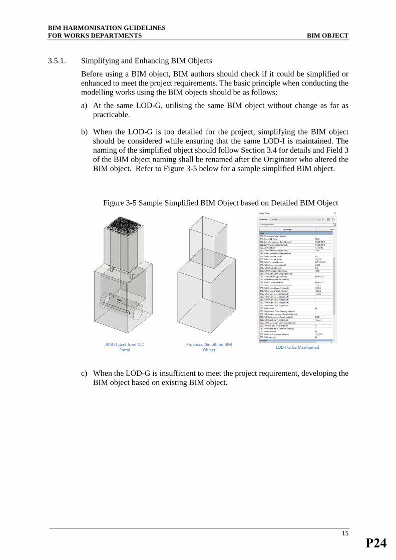
b) When the LOD-G is too detailed for the project, simplifying the BIM object should be considered while ensuring that the same LOD-I is maintained. The naming of the simplified object should follow Section 3.4 for details and Field 3 of the BIM object naming shall be renamed after the Originator who altered the BIM object. Refer to Figure 3-5 below for a sample simplified BIM object.
Figure 3-5 Sample Simplified BIM Object based on Detailed BIM Object
c) When the LOD-G is insufficient to meet the project requirement, developing the
BIM object based on existing BIM object.
P24
BIM HARMONISATION GUIDELINES FOR WORKS DEPARTMENTS BIM OBJECT
16
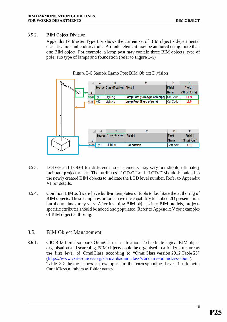
3.5.2. BIM Object Division Appendix IV Master Type List shows the current set of BIM object’s departmental classification and codifications. A model element may be authored using more than one BIM object. For example, a lamp post may contain three BIM objects: type of pole, sub type of lamps and foundation (refer to Figure 3-6).
Figure 3-6 Sample Lamp Post BIM Object Division
3.5.3. LOD-G and LOD-I for different model elements may vary but should ultimately facilitate project needs. The attributes “LOD-G” and “LOD-I” should be added to the newly created BIM objects to indicate the LOD level number. Refer to Appendix VI for details.
3.5.4. Common BIM software have built-in templates or tools to facilitate the authoring of BIM objects. These templates or tools have the capability to embed 2D presentation, but the methods may vary. After inserting BIM objects into BIM models, project-specific attributes should be added and populated. Refer to Appendix V for examples of BIM object authoring.
3.6. BIM Object Management
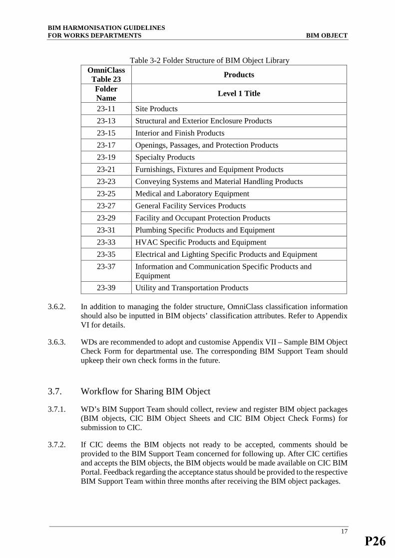
3.6.1. CIC BIM Portal supports OmniClass classification. To facilitate logical BIM object organisation and searching, BIM objects could be organised in a folder structure as the first level of OmniClass according to “OmniClass version 2012 Table 23” (https://www.csiresources.org/standards/omniclass/standards-omniclass-about). Table 3-2 below shows an example for the corresponding Level 1 title with OmniClass numbers as folder names.
P25
BIM HARMONISATION GUIDELINES FOR WORKS DEPARTMENTS BIM OBJECT
17
Table 3-2 Folder Structure of BIM Object Library OmniClass
Table 23 Products
Folder Name Level 1 Title
23-11 Site Products 23-13 Structural and Exterior Enclosure Products 23-15 Interior and Finish Products 23-17 Openings, Passages, and Protection Products 23-19 Specialty Products 23-21 Furnishings, Fixtures and Equipment Products 23-23 Conveying Systems and Material Handling Products 23-25 Medical and Laboratory Equipment 23-27 General Facility Services Products 23-29 Facility and Occupant Protection Products 23-31 Plumbing Specific Products and Equipment 23-33 HVAC Specific Products and Equipment 23-35 Electrical and Lighting Specific Products and Equipment 23-37 Information and Communication Specific Products and
Equipment 23-39 Utility and Transportation Products
3.6.2. In addition to managing the folder structure, OmniClass classification information should also be inputted in BIM objects’ classification attributes. Refer to Appendix VI for details.
3.6.3. WDs are recommended to adopt and customise Appendix VII – Sample BIM Object Check Form for departmental use. The corresponding BIM Support Team should upkeep their own check forms in the future.
3.7. Workflow for Sharing BIM Object
3.7.1. WD’s BIM Support Team should collect, review and register BIM object packages (BIM objects, CIC BIM Object Sheets and CIC BIM Object Check Forms) for submission to CIC.
3.7.2. If CIC deems the BIM objects not ready to be accepted, comments should be provided to the BIM Support Team concerned for following up. After CIC certifies and accepts the BIM objects, the BIM objects would be made available on CIC BIM Portal. Feedback regarding the acceptance status should be provided to the respective BIM Support Team within three months after receiving the BIM object packages.
P26
BIM HARMONISATION GUIDELINES FOR WORKS DEPARTMENTS BIM OBJECT
18
3.7.3. WDs should notify project awardees to utilise BIM objects shared at CIC BIM Portal as far as practicable and make reference to WDs’ BIM objects that have been internally accepted for use.
P27
BIM HARMONISATION GUIDELINES FOR WORKS DEPARTMENTS FEDERATION AND BIM MODEL NAMING
19
4. Federation and BIM Model Naming
4.1. BIM Model Naming Principle
4.1.1. This section provides the principle to set out the BIM model naming (information container ID) and federation strategy to achieve consistent BIM model federation. A hierarchical and logical model organisation can serve to facilitate BIM management and subsequent LOIN implementation such as LOD-I management and colour appearance.
4.1.2. ISO 19650‑2:2018 Part 2 Section 5.1.7(a) states that each information container shall have a unique ID, based upon agreed and documented convention comprising fields separated by a delimiter, within a project Common Data Environment (CDE). Unique ID should be consistent among WDs to facilitate interdepartmental information exchange via the BIM DR. The hierarchy should include the following descriptions: a) What asset is the BIM model related to; b) Who is the originator of information; c) Which geospatial zone and system(s) it belongs to; d) Where it is located; e) Which discipline it is related to; f) What type of information the model contains; and g) What unique information is necessary to further distinguish the model from
others.
4.1.3. ISO 19650‑2:2018 Part 2 Section 5.1.7(b) states that the project's common data environment shall enable each field to be assigned a value from an agreed and documented codification standard. The codification standard would set out: a) Field sequence; b) Information container ID fields (and sub-fields if applicable); c) Description of each information container ID field and sub-field; d) Whether the field is required or optional; e) Format which defines length and alphabetic, numeric or alphanumeric; f) Whether the codification is common or project-specific; and g) Where the detailed list of codification information can be located.
4.1.4. Information container ID, model division, federation and corresponding abbreviation codes should be sustainable and consider the future potential use of metadata.
P28
BIM HARMONISATION GUIDELINES FOR WORKS DEPARTMENTS FEDERATION AND BIM MODEL NAMING
20
4.2. Information Container Identification Fields
4.2.1. Model naming shall follow the information container ID fields sequence and corresponding abbreviation codes. The arrangement of information container ID fields is primarily derived from the principles in ISO 19650 to suit the common practices within WDs. UK Annex mentioned in ISO 19650 was referenced to develop the naming sequence. Naming convention under the “CIC BIM Standards - General: December 2020 Edition” (with Hong Kong Local Annex of ISO 19650-2:2018) was also aligned with the naming convention of this Guide.
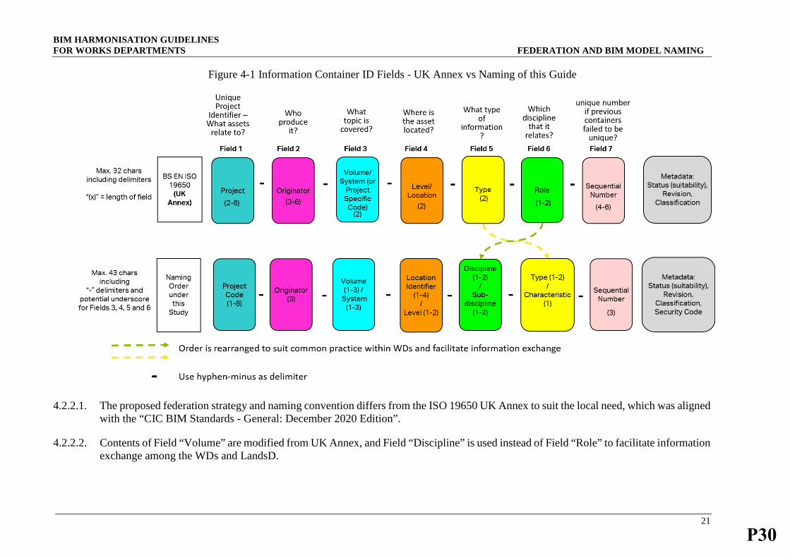
4.2.2. Refer to Figure 4-1 below for the comparison between information container ID fields of the UK Annex and naming convention of this Guide.
P29
BIM HARMONISATION GUIDELINES FOR WORKS DEPARTMENTS FEDERATION AND BIM MODEL NAMING
21
Figure 4-1 Information Container ID Fields - UK Annex vs Naming of this Guide
4.2.2.1. The proposed federation strategy and naming convention differs from the ISO 19650 UK Annex to suit the local need, which was aligned with the “CIC BIM Standards - General: December 2020 Edition”.
4.2.2.2. Contents of Field “Volume” are modified from UK Annex, and Field “Discipline” is used instead of Field “Role” to facilitate information exchange among the WDs and LandsD.
P30
BIM HARMONISATION GUIDELINES FOR WORKS DEPARTMENTS FEDERATION AND BIM MODEL NAMING
22
4.2.2.3. The maximum total length of model names is 43 characters (including delimiters and information dividers; excluding file extension). Appendix VIII – Federation Strategy Diagrams and Naming Examples shows examples for reference.
4.2.2.4. Information container ID fields are reserved for information pertinent to information exchange between WDs. To ensure that the total length of model naming is manageable, metadata should only be used when: a) The information container ID field is only relevant to individual WDs; b) The identification does not facilitate work breakdown structure; c) The length of the information container ID field is relatively long; or d) The detailed descriptions would lose the meaning and adversely affect information exchange if abbreviated.
The input format for metadata that facilitate data filtering (e.g. security code) should be consistent. Flexibility on the input format is allowed for other cases.
4.2.2.5. Mapping tables (Appendices XII to XVII) have been provided for the WDs to bridge the existing codes and harmonised codes.
P31
BIM HARMONISATION GUIDELINES FOR WORKS DEPARTMENTS FEDERATION AND BIM MODEL NAMING
23
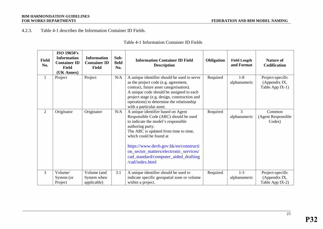
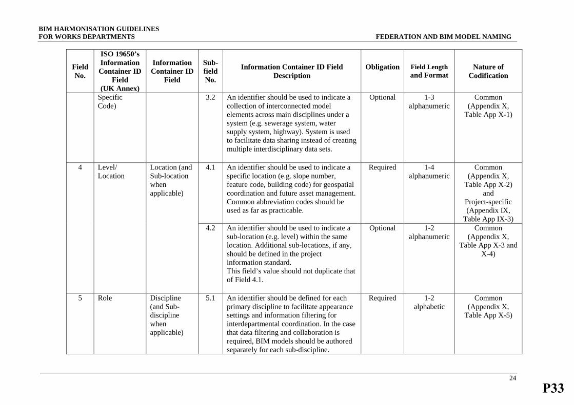
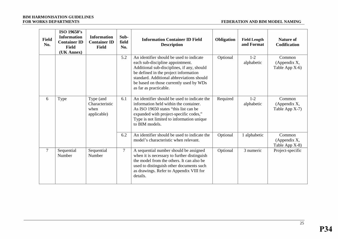
4.2.3. Table 4-1 describes the Information Container ID Fields.
Table 4-1 Information Container ID Fields
Field No.
ISO 19650’s Information Container ID
Field (UK Annex)
Information Container ID
Field
Sub-field No.
Information Container ID Field Description
Obligation
Field Length and Format
Nature of Codification
1 Project Project N/A A unique identifier should be used to serve as the project code (e.g. agreement, contract, future asset categorisation). A unique code should be assigned to each project stage (e.g. design, construction and operations) to determine the relationship with a particular asset.
Required
1-8 alphanumeric
Project-specific (Appendix IX,
Table App IX-1)
2 Originator Originator N/A A unique identifier based on Agent Responsible Code (ARC) should be used to indicate the model’s responsible authoring party. The ARC is updated from time to time, which could be found at https://www.devb.gov.hk/en/construction_sector_matters/electronic_services/cad_standard/computer_aided_drafting/cad/index.html
Required
3 alphanumeric
Common (Agent Responsible
Codes)
3 Volume/ System (or Project
Volume (and System when applicable)
3.1 A unique identifier should be used to indicate specific geospatial zone or volume within a project.
Required
1-3 alphanumeric
Project-specific (Appendix IX,
Table App IX-2)
P32
BIM HARMONISATION GUIDELINES FOR WORKS DEPARTMENTS FEDERATION AND BIM MODEL NAMING
24
Field No.
ISO 19650’s Information Container ID
Field (UK Annex)
Information Container ID
Field
Sub-field No.
Information Container ID Field Description
Obligation
Field Length and Format
Nature of Codification
Specific Code)
3.2 An identifier should be used to indicate a collection of interconnected model elements across main disciplines under a system (e.g. sewerage system, water supply system, highway). System is used to facilitate data sharing instead of creating multiple interdisciplinary data sets.
Optional
1-3 alphanumeric
Common (Appendix X,
Table App X‑1)
4 Level/ Location
Location (and Sub-location when applicable)
4.1 An identifier should be used to indicate a specific location (e.g. slope number, feature code, building code) for geospatial coordination and future asset management. Common abbreviation codes should be used as far as practicable.
Required
1-4 alphanumeric
Common (Appendix X,
Table App X-2) and
Project-specific (Appendix IX,
Table App IX-3) 4.2 An identifier should be used to indicate a
sub-location (e.g. level) within the same location. Additional sub-locations, if any, should be defined in the project information standard. This field’s value should not duplicate that of Field 4.1.
Optional
1-2 alphanumeric
Common (Appendix X,
Table App X-3 and X-4)
5 Role Discipline (and Sub-discipline when applicable)
5.1 An identifier should be defined for each primary discipline to facilitate appearance settings and information filtering for interdepartmental coordination. In the case that data filtering and collaboration is required, BIM models should be authored separately for each sub-discipline.
Required
1-2 alphabetic
Common (Appendix X,
Table App X-5)
P33
BIM HARMONISATION GUIDELINES FOR WORKS DEPARTMENTS FEDERATION AND BIM MODEL NAMING
25
Field No.
ISO 19650’s Information Container ID
Field (UK Annex)
Information Container ID
Field
Sub-field No.
Information Container ID Field Description
Obligation
Field Length and Format
Nature of Codification
5.2 An identifier should be used to indicate each sub-discipline appointment. Additional sub-disciplines, if any, should be defined in the project information standard. Additional abbreviations should be based on those currently used by WDs as far as practicable.
Optional
1-2 alphabetic
Common (Appendix X,
Table App X-6)
6 Type Type (and Characteristic when applicable)
6.1 An identifier should be used to indicate the information held within the container. As ISO 19650 states “this list can be expanded with project-specific codes,” Type is not limited to information unique to BIM models.
Required
1-2 alphabetic
Common (Appendix X,
Table App X-7)
6.2 An identifier should be used to indicate the model’s characteristic when relevant.
Optional
1 alphabetic
Common (Appendix X,
Table App X-8) 7 Sequential
Number Sequential Number
7 A sequential number should be assigned when it is necessary to further distinguish the model from the others. It can also be used to distinguish other documents such as drawings. Refer to Appendix VIII for details.
Optional
3 numeric
Project-specific
P34
BIM HARMONISATION GUIDELINES FOR WORKS DEPARTMENTS FEDERATION AND BIM MODEL NAMING
26
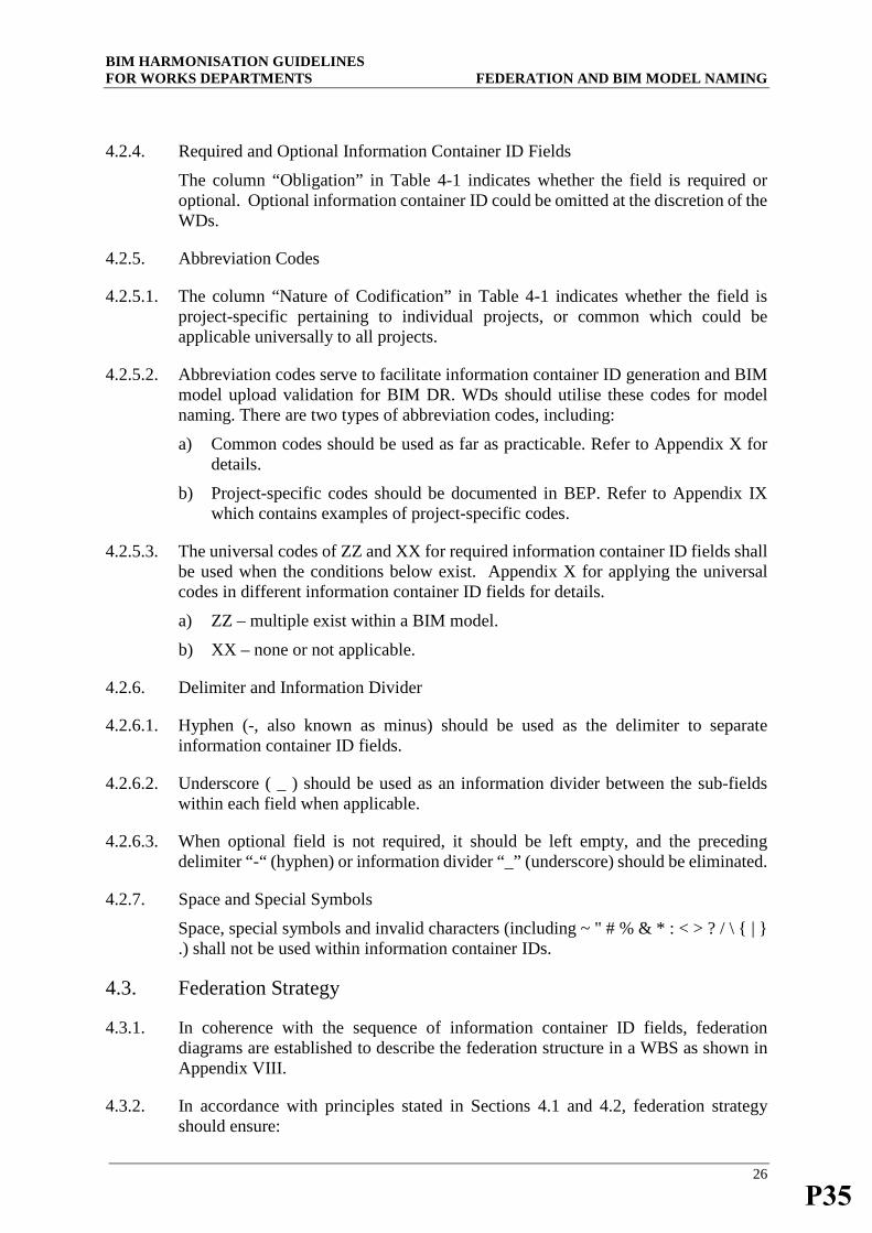
4.2.4. Required and Optional Information Container ID Fields The column “Obligation” in Table 4-1 indicates whether the field is required or optional. Optional information container ID could be omitted at the discretion of the WDs.
4.2.5. Abbreviation Codes
4.2.5.1. The column “Nature of Codification” in Table 4-1 indicates whether the field is project-specific pertaining to individual projects, or common which could be applicable universally to all projects.
4.2.5.2. Abbreviation codes serve to facilitate information container ID generation and BIM model upload validation for BIM DR. WDs should utilise these codes for model naming. There are two types of abbreviation codes, including: a) Common codes should be used as far as practicable. Refer to Appendix X for
details. b) Project-specific codes should be documented in BEP. Refer to Appendix IX
which contains examples of project-specific codes.
4.2.5.3. The universal codes of ZZ and XX for required information container ID fields shall be used when the conditions below exist. Appendix X for applying the universal codes in different information container ID fields for details. a) ZZ – multiple exist within a BIM model. b) XX – none or not applicable.
4.2.6. Delimiter and Information Divider
4.2.6.1. Hyphen (-, also known as minus) should be used as the delimiter to separate information container ID fields.
4.2.6.2. Underscore ( _ ) should be used as an information divider between the sub-fields within each field when applicable.
4.2.6.3. When optional field is not required, it should be left empty, and the preceding delimiter “-“ (hyphen) or information divider “_” (underscore) should be eliminated.
4.2.7. Space and Special Symbols Space, special symbols and invalid characters (including ~ " # % & * : < > ? / \ { | }.) shall not be used within information container IDs.
4.3. Federation Strategy
4.3.1. In coherence with the sequence of information container ID fields, federation diagrams are established to describe the federation structure in a WBS as shown in Appendix VIII.
4.3.2. In accordance with principles stated in Sections 4.1 and 4.2, federation strategy should ensure:
P35
BIM HARMONISATION GUIDELINES FOR WORKS DEPARTMENTS FEDERATION AND BIM MODEL NAMING
27
a) The information container breakdown (model division) conforms to requirements from departmental information owners (if known);
b) The breakdown is sufficient to facilitate data filtering for information sharing according to Appendix III for details;
c) File size limitation conforms to the maximum as stated in Section 2.3.1; and d) The information is clearly grouped.
4.4. BIM Model Naming In accordance with Sections 4.1 – 4.3, model naming should be in the format as shown below. <project code> - <originator> - <volume_system> - <location_sub-location> - <discipline_subdiscipline> - <type_characteristic> - <sequential number> . <file extension> Refer to Appendix VIII for examples.
4.5. Naming of Drawings Generated from BIM model WDs should consider adopting the model naming format for drawing file naming. Refer to Appendix VIII for an example.
P36
BIM HARMONISATION GUIDELINES FOR WORKS DEPARTMENTS LOIN IMPLEMENTATION
28
5. LOIN Implementation To enable future information exchange using the BIM DR, WDs shall follow the subsequent principles when authoring BIM files.
5.1. Aligned BIM Standards
5.1.1. This Guide should serve as the aligned standards for future information exchange.
5.2. BEP
5.2.1. Referring to Section 2.1.2, BEP should be authored with consideration of asset owner requirements. BEP should specify the BIM standards applicable to the project in addition to this Guide.
5.2.2. BEP should be authored in accordance with departmental BEP templates or DEVB’s BEP reference template (if the former is unavailable). In addition, BEP should document the following: a) Information owner’s identification; b) Project information requirements (e.g. element-specific LOD-I attributes in table
or list formats); c) Project-specific federation strategy; and d) Project-specific codes for BIM model naming (e.g. project code(s), location
codes).
5.3. BIM Modelling Setting
5.3.1. Coordinate System All BIM files shall be authored and annotated directly with reference to the Hong Kong 1980 Grid (HK 1980 Grid) and Hong Kong Principal Datum (HKPD).
5.3.2. BIM Template Project-specific BIM template should be prepared for required software used and file formats (e.g. .rte for Revit and .dwt for Civil 3D). The template should include: a) Project and zone boundaries; b) Coordinate system; c) Grid; and d) Common attributes relevant to the project.
5.3.3. Mandatory Requirements for BIM modelling
P37
BIM HARMONISATION GUIDELINES FOR WORKS DEPARTMENTS LOIN IMPLEMENTATION
29
a) Use the object developed from the BIM Object library, instead of creating own object, as far as practicable to maintain the consistency, such as inserting point and BIM attributes of the object.
b) If new object is developed, register the object in the CIC object library timely. c) Do not add user defined parameter with the same name as the system built-in
parameters. Use a prefix such as departmental abbreviation code to differentiate the system built-in parameters from the user-defined parameters.
d) Linked files will not be exported to IFC by default, keep them in the native file
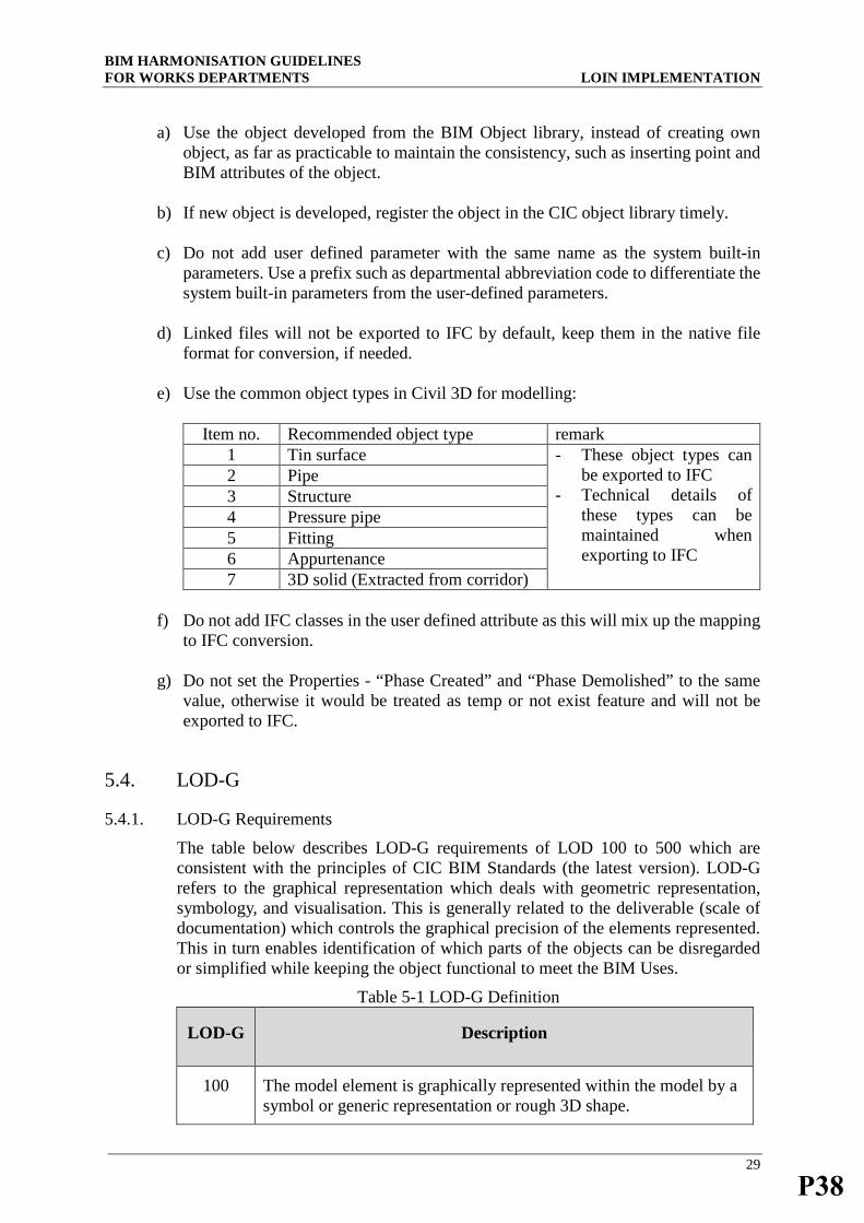
format for conversion, if needed. e) Use the common object types in Civil 3D for modelling:
Item no. Recommended object type remark 1 Tin surface - These object types can
be exported to IFC - Technical details of
these types can be maintained when exporting to IFC
2 Pipe 3 Structure 4 Pressure pipe 5 Fitting 6 Appurtenance 7 3D solid (Extracted from corridor)
f) Do not add IFC classes in the user defined attribute as this will mix up the mapping
to IFC conversion.
g) Do not set the Properties - “Phase Created” and “Phase Demolished” to the same value, otherwise it would be treated as temp or not exist feature and will not be exported to IFC.
5.4. LOD-G
5.4.1. LOD-G Requirements The table below describes LOD-G requirements of LOD 100 to 500 which are consistent with the principles of CIC BIM Standards (the latest version). LOD-G refers to the graphical representation which deals with geometric representation, symbology, and visualisation. This is generally related to the deliverable (scale of documentation) which controls the graphical precision of the elements represented. This in turn enables identification of which parts of the objects can be disregarded or simplified while keeping the object functional to meet the BIM Uses.
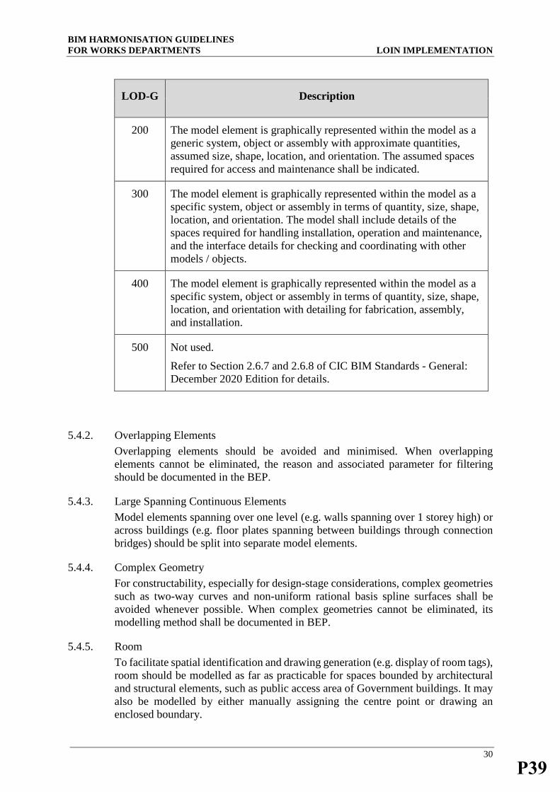
Table 5-1 LOD-G Definition
LOD-G Description
100 The model element is graphically represented within the model by a symbol or generic representation or rough 3D shape.
P38
BIM HARMONISATION GUIDELINES FOR WORKS DEPARTMENTS LOIN IMPLEMENTATION
30
LOD-G Description
200 The model element is graphically represented within the model as a generic system, object or assembly with approximate quantities, assumed size, shape, location, and orientation. The assumed spaces required for access and maintenance shall be indicated.
300 The model element is graphically represented within the model as a specific system, object or assembly in terms of quantity, size, shape, location, and orientation. The model shall include details of the spaces required for handling installation, operation and maintenance, and the interface details for checking and coordinating with other models / objects.
400 The model element is graphically represented within the model as a specific system, object or assembly in terms of quantity, size, shape, location, and orientation with detailing for fabrication, assembly, and installation.
500 Not used. Refer to Section 2.6.7 and 2.6.8 of CIC BIM Standards - General: December 2020 Edition for details.
5.4.2. Overlapping Elements Overlapping elements should be avoided and minimised. When overlapping elements cannot be eliminated, the reason and associated parameter for filtering should be documented in the BEP.
5.4.3. Large Spanning Continuous Elements Model elements spanning over one level (e.g. walls spanning over 1 storey high) or across buildings (e.g. floor plates spanning between buildings through connection bridges) should be split into separate model elements.
5.4.4. Complex Geometry For constructability, especially for design-stage considerations, complex geometries such as two-way curves and non-uniform rational basis spline surfaces shall be avoided whenever possible. When complex geometries cannot be eliminated, its modelling method shall be documented in BEP.
5.4.5. Room To facilitate spatial identification and drawing generation (e.g. display of room tags), room should be modelled as far as practicable for spaces bounded by architectural and structural elements, such as public access area of Government buildings. It may also be modelled by either manually assigning the centre point or drawing an enclosed boundary.
P39
BIM HARMONISATION GUIDELINES FOR WORKS DEPARTMENTS LOIN IMPLEMENTATION
31
5.4.6. Operation and Maintenance Space For building services and mechanical type of BIM elements, the operation and maintenance space are concerned information for asset owner. It is suggested to model the operation and maintenance space for these kinds of BIM elements, such as control panel/switch box with panel door, vent relief valve (VRV) unit with control valve set, etc.
5.5. LOD-I
5.5.1. LOD-I Grouping Attributes (LOD-I) could be grouped by general properties, design properties, classification properties (e.g. OmniClass) and installation information. Under each grouping, the list of attributes may differ due to WDs’ LOD-I requirements. The creation methods of attributes for BIM objects would vary by software. Refer to Appendix VI for details.
5.5.2. Project Information To facilitate conversion engine’s processes, all relevant project information (such as Organisation Name, Project Issue Date, Client Name, Project Address, Project Name and Project Number) should be inputted in all BIM files as part of the LOD-I for metadata extraction and geolocation. Refer to Appendix VI which shows the project information input methods of Revit and Civil 3D.
5.5.3. BIM Attributes (Attributes) BIM models and BIM objects should be authored with required general properties and attributes. Refer to Appendix VI for details.
5.5.4. Language Unless specifically required by the BEP, all project information and attributes should be in the English language.
5.6. Appearance
5.6.1. Within each WD, model elements’ shading colours shall follow RGB codes specified based on the prevailing systems in WDs’ guidelines for design authoring. For 3D coordination, WDs’ own colour standards may be adopted. Deviations, if any, should be documented in BEP.
5.6.2. For interdepartmental 3D coordination between WDs, colour appearance should be based on Discipline (Field 5.1 of the naming convention) as specified in Section 4.2. BIM DR will be capable of setting the colour appearance of various Disciplines in accordance with Tables 5-2 and 5-3.
P40
BIM HARMONISATION GUIDELINES FOR WORKS DEPARTMENTS LOIN IMPLEMENTATION
32
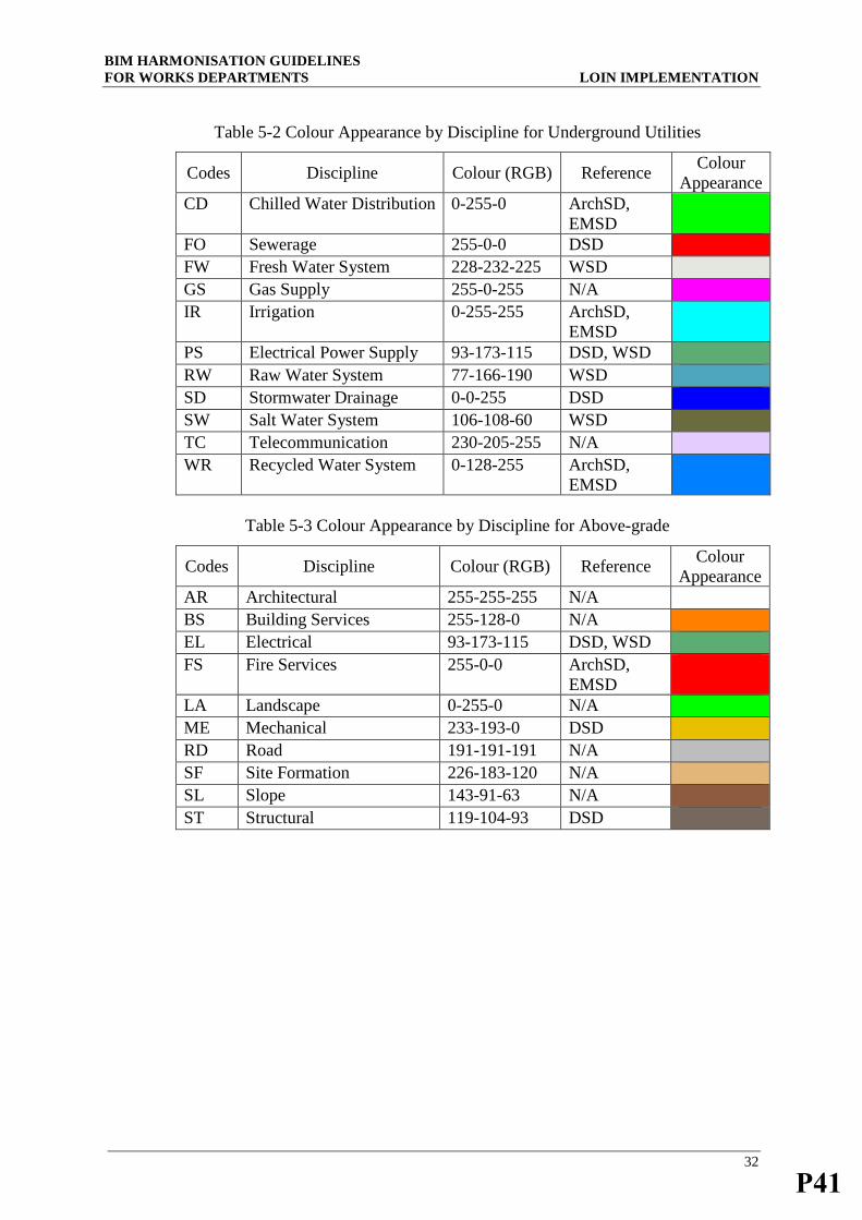
Table 5-2 Colour Appearance by Discipline for Underground Utilities
Codes Discipline Colour (RGB) Reference Colour Appearance
CD Chilled Water Distribution 0-255-0 ArchSD, EMSD
FO Sewerage 255-0-0 DSD FW Fresh Water System 228-232-225 WSD GS Gas Supply 255-0-255 N/A IR Irrigation 0-255-255 ArchSD,
EMSD
PS Electrical Power Supply 93-173-115 DSD, WSD RW Raw Water System 77-166-190 WSD SD Stormwater Drainage 0-0-255 DSD SW Salt Water System 106-108-60 WSD TC Telecommunication 230-205-255 N/A WR Recycled Water System 0-128-255 ArchSD,
EMSD
Table 5-3 Colour Appearance by Discipline for Above-grade
Codes Discipline Colour (RGB) Reference Colour Appearance
AR Architectural 255-255-255 N/A BS Building Services 255-128-0 N/A EL Electrical 93-173-115 DSD, WSD FS Fire Services 255-0-0 ArchSD,
EMSD
LA Landscape 0-255-0 N/A ME Mechanical 233-193-0 DSD RD Road 191-191-191 N/A SF Site Formation 226-183-120 N/A SL Slope 143-91-63 N/A ST Structural 119-104-93 DSD
P41
BIM HARMONISATION GUIDELINES FOR WORKS DEPARTMENTS THE WAY FORWARD
33
6. The Way Forward This Guide provides harmonised BIM standards for the use by WDs in capital works projects adopting BIM. This Guide and its appendices may be subject to change and adaptation to be applicable across all WDs' projects. It is therefore important to set out the recommended upkeeping and project close-out protocols.
6.1. Regular Review and Update
6.1.1. DEVB(WB) is the responsible party of this Guide. Corresponding BIM Support Teams of the WDs shall coordinate any departmental comments and recommendations for necessary discussion at the DEVB BIM Work Group Meeting.
6.1.2. This Guide should be up kept and updated periodically. The appendices that would need updating include: a) Appendix III – Data Filtering Rule Table should be reviewed when the WDs’
data requirements have been changed. b) Appendix X – Common Codes for Naming should be centrally managed and
updated. Additional codes should be added to the list when commonly used. Obsolete codes should be removed from active use but kept reference for back tracing, if and when needed.
c) Appendix VIII – Federation Strategy Diagrams and Naming Examples should be reviewed and updated as necessary to support proper data filtering.
d) Appendix VI – LOD-I Requirements, Creation and Extraction may be subject to update if more LOD-I is required in the future (especially for asset management), or if information creation and extraction are changed due to technological advancement.
6.2. Codification Management
6.2.1. Each project would have its project specific codes, which, together with the common codes listed in Appendix X, could be used to facilitate validation of the BIM file names. It is recommended to conduct validation processes through CDEs, BIM DR or other relevant systematic methods. Appendix XI contains a Sample Spreadsheet for BIM File Name Validation of this Guide for a sample spreadsheet to validate BIM file names.
6.3. Project Close-out Protocols In accordance with Section 5.8.3 of ISO 19650-2:2018, project close-out activities include “archiving the project information model” and “compiling lessons learned for future projects”. This section contains recommended project close-out protocols for WDs’ consideration.
P42
BIM HARMONISATION GUIDELINES FOR WORKS DEPARTMENTS THE WAY FORWARD
34
6.3.1. A project-specific checklist could be authored and included in each project’s BEP, with reference to: a) Asset owners’ checklists of BIM attributes (which may have detailed LOD-I
requirements); b) WDs’ and project awardees’ own checklists; c) Sample BIM Object Check Form (refer to Appendix VII); and d) Sample Project Close-out Checklist (refer to Appendix XVIII).
6.4. BIM / GIS Integration
6.4.1. A geospatial-based federation strategy and open format should be adopted to ensure coherence amongst BIM models. These BIM models should conform to requirements outlined in previous sections to facilitate open format conversion for BIM DR, as well as BIM / GIS integration amongst WDs and LandsD.
6.4.2. Going forward, consistent BIM data could facilitate interdepartmental and intradepartmental BIM / GIS integration and applications via a standard approach. The success of such integration would be contingent upon consistent approaches, including the adoption of: a) Information container sequence and code; b) Availability to share more information to the extent that it does not conflict
with restricted or confidential information; and c) Support of open format use.
6.5. Departmental Transition
6.5.1. This Guide aims to facilitate information exchange between WDs and LandsD. The mapping tables in Appendices XII to XVII have outlined differences between this Guide and the departmental standards, at the time the Study of CEDD was carried out, that are relevant to interdepartmental information exchange. WDs are suggested to reconcile these differences within their respective departmental standards.
6.6. Information Management
6.6.1. As BIM maturity increases among WDs, information management conforming to ISO 19650 will become more relevant.
6.6.2. It is suggested to dedicate a section in the BEP on Project Information Standard, which sets out the standards and protocols that the project should be followed. It should contain the following: a) A list of the standards that are to be followed; b) Naming conventions that are to be used or any specific project codes;
P43
BIM HARMONISATION GUIDELINES FOR WORKS DEPARTMENTS THE WAY FORWARD
35
c) Method(s) to generate applicable 2D / CAD drawings from the relevant BIM object / models;
d) Define what classification of WBS and Task Information Delivery Plan (TIDP) should be used in detail, which relates to information container breakdown structure on project-specific basis; and
e) How LOIN should be described.
6.6.3. Information Delivery Plan
6.6.3.1. While BEPs have already been prevalently used by most WDs as one of the information management tools in BIM projects, in accordance with ISO 19650, an information delivery plan is required in addition to BEP to manage information in the lifecycle of a project. Information delivery plan should not only outline the principles of information management using BIM, but also be applicable to other information management aspects of a project, such as drawings, data files, visualisation and simulations.
6.6.3.2. The conversion engine utilises a common key approach to link attributes and geometries. This could facilitate LandsD’s 3D digital map development and allow single query for 3D models. To maintain the attributes in tabular format in the long term, the common key approach should be regularly reviewed.
6.6.4. Data Security Classification
6.6.4.1. There are three security tiers, namely unclassified, restricted and confidential. If future BIM DR access expands beyond WDs, additional security definitions may be created by adding abbreviation codes to the “Security” metadata field or CDE folder management.
6.6.5. CDE
6.6.5.1. Establishment of project-CDE, as an overarching CDE for its constituent consultancy studies and works contracts, if appropriate, should take into consideration of information security issues. As per ISO19650, CDE is an “agreed source of information for any given project or asset, for collecting, managing and disseminating each information container through a managed process”. CDE may serve more functions than data repositories. CDE capabilities could ultimately surpass those defined in ISO 19650 to fulfil project needs as the single source of truth (e.g. central information depository and lifecycle management for documents, contracts, reports, bids and model information).
P44

BIM HARMONISATION GUIDELINES FOR WORKS DEPARTMENTS THE WAY FORWARD
36
End of the Guide
P45

DEVB BIM HARMONISATION GUIDELINES FOR WORKS DEPARTMENTS APPENDIX I
– ISO 19650 Terminologies
P46
DEVB BIM HARMONISATION GUIDELINES FOR WORKS DEPARTMENTS APPENDIX I
I-1
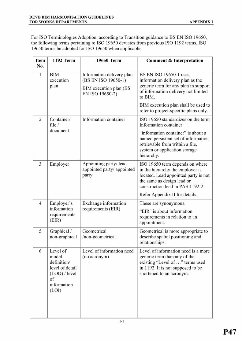
For ISO Terminologies Adoption, according to Transition guidance to BS EN ISO 19650, the following terms pertaining to ISO 19650 deviates from previous ISO 1192 terms. ISO 19650 terms be adopted for ISO 19650 when applicable.
Item No.
1192 Term 19650 Term Comment & Interpretation
1 BIM execution plan
Information delivery plan (BS EN ISO 19650‑1) BIM execution plan (BS EN ISO 19650‑2)
BS EN ISO 19650‑1 uses information delivery plan as the generic term for any plan in support of information delivery not limited to BIM. BIM execution plan shall be used to refer to project-specific plans only.
2 Container/ file / document
Information container ISO 19650 standardizes on the term Information container “information container” is about a named persistent set of information retrievable from within a file, system or application storage hierarchy.
3 Employer Appointing party/ lead appointed party/ appointed party
ISO 19650 term depends on where in the hierarchy the employer is located. Lead appointed party is not the same as design lead or construction lead in PAS 1192‑2. Refer Appendix II for details.
4 Employer’s information requirements (EIR)
Exchange information requirements (EIR)
These are synonymous. “EIR" is about information requirements in relation to an appointment.
5 Graphical / non-graphical
Geometrical /non‑geometrical
Geometrical is more appropriate to describe spatial positioning and relationships.
6 Level of model definition/ level of detail (LOD) / level of information (LOI)
Level of information need (no acronym)
Level of information need is a more generic term than any of the existing “Level of …” terms used in 1192. It is not supposed to be shortened to an acronym.
P47
DEVB BIM HARMONISATION GUIDELINES FOR WORKS DEPARTMENTS APPENDIX I
I-2
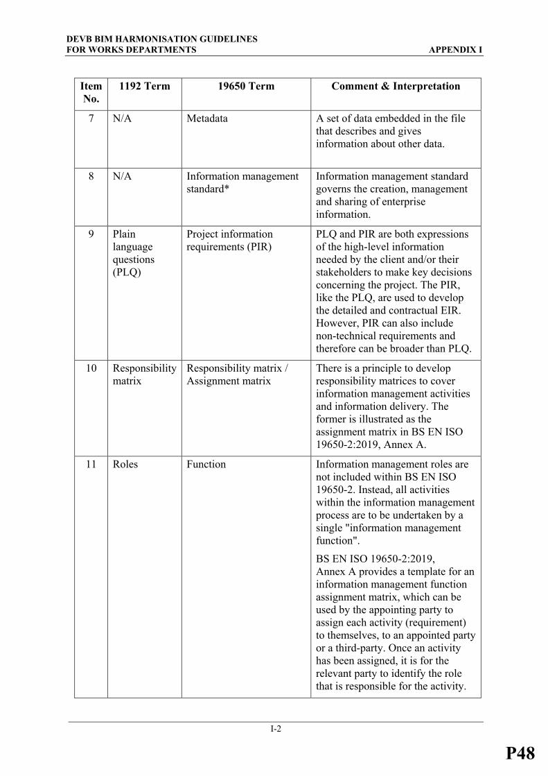
Item No.
1192 Term 19650 Term Comment & Interpretation
7 N/A Metadata A set of data embedded in the file that describes and gives information about other data.
8 N/A Information management
standard* Information management standard governs the creation, management and sharing of enterprise information.
9 Plain language questions (PLQ)
Project information requirements (PIR)
PLQ and PIR are both expressions of the high-level information needed by the client and/or their stakeholders to make key decisions concerning the project. The PIR, like the PLQ, are used to develop the detailed and contractual EIR. However, PIR can also include non-technical requirements and therefore can be broader than PLQ.
10 Responsibility matrix
Responsibility matrix / Assignment matrix
There is a principle to develop responsibility matrices to cover information management activities and information delivery. The former is illustrated as the assignment matrix in BS EN ISO 19650‑2:2019, Annex A.
11 Roles Function Information management roles are not included within BS EN ISO 19650‑2. Instead, all activities within the information management process are to be undertaken by a single "information management function". BS EN ISO 19650‑2:2019, Annex A provides a template for an information management function assignment matrix, which can be used by the appointing party to assign each activity (requirement) to themselves, to an appointed party or a third-party. Once an activity has been assigned, it is for the relevant party to identify the role that is responsible for the activity.
P48
DEVB BIM HARMONISATION GUIDELINES FOR WORKS DEPARTMENTS APPENDIX I
I-3
Item No.
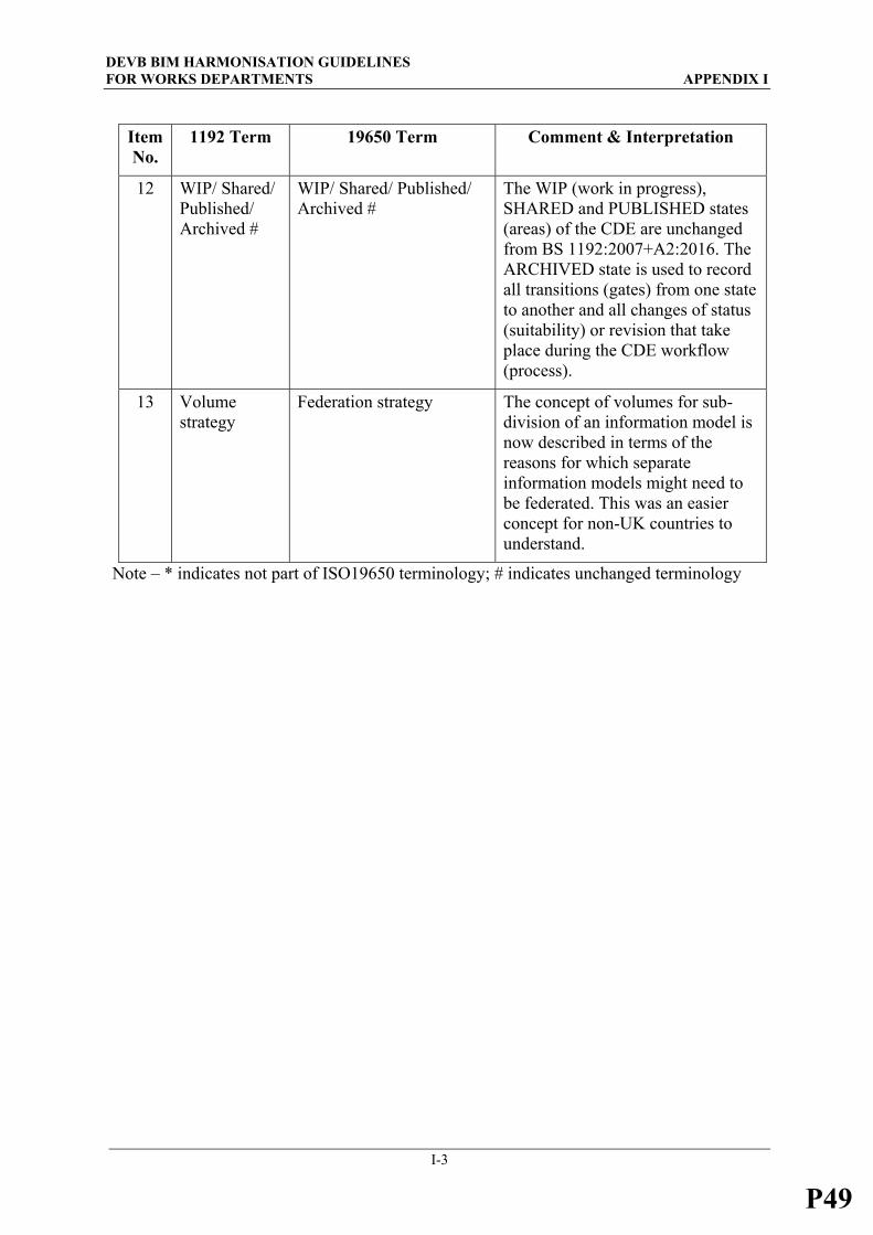
1192 Term 19650 Term Comment & Interpretation
12 WIP/ Shared/ Published/ Archived #
WIP/ Shared/ Published/ Archived #
The WIP (work in progress), SHARED and PUBLISHED states (areas) of the CDE are unchanged from BS 1192:2007+A2:2016. The ARCHIVED state is used to record all transitions (gates) from one state to another and all changes of status (suitability) or revision that take place during the CDE workflow (process).
13 Volume strategy
Federation strategy The concept of volumes for sub-division of an information model is now described in terms of the reasons for which separate information models might need to be federated. This was an easier concept for non-UK countries to understand.
Note – * indicates not part of ISO19650 terminology; # indicates unchanged terminology
P49

DEVB BIM HARMONISATION GUIDELINES FOR WORKS DEPARTMENTS APPENDIX II
– Information Responsibility Assignment Matrix
P50
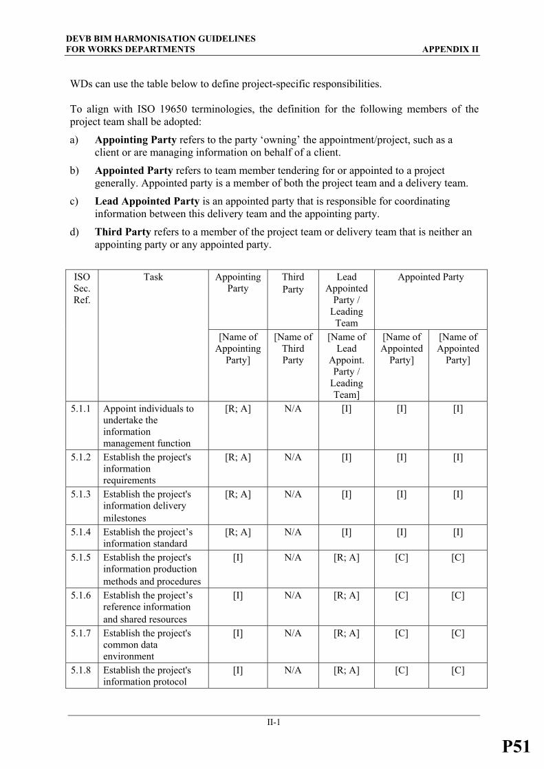
DEVB BIM HARMONISATION GUIDELINES FOR WORKS DEPARTMENTS APPENDIX II
II-1
WDs can use the table below to define project-specific responsibilities. To align with ISO 19650 terminologies, the definition for the following members of the project team shall be adopted: a) Appointing Party refers to the party ‘owning’ the appointment/project, such as a
client or are managing information on behalf of a client. b) Appointed Party refers to team member tendering for or appointed to a project
generally. Appointed party is a member of both the project team and a delivery team. c) Lead Appointed Party is an appointed party that is responsible for coordinating
information between this delivery team and the appointing party. d) Third Party refers to a member of the project team or delivery team that is neither an
appointing party or any appointed party.
ISO Sec. Ref.
Task Appointing Party
Third Party
Lead Appointed
Party / Leading
Team
Appointed Party
[Name of Appointing
Party]
[Name of Third Party
[Name of Lead
Appoint. Party /
Leading Team]
[Name of Appointed
Party]
[Name of Appointed
Party]
5.1.1 Appoint individuals to undertake the information management function
[R; A] N/A [I] [I] [I]
5.1.2 Establish the project's information requirements
[R; A] N/A [I] [I] [I]
5.1.3 Establish the project's information delivery milestones
[R; A] N/A [I] [I] [I]
5.1.4 Establish the project’s information standard
[R; A] N/A [I] [I] [I]
5.1.5 Establish the project's information production methods and procedures
[I] N/A [R; A] [C] [C]
5.1.6 Establish the project’s reference information and shared resources
[I] N/A [R; A] [C] [C]
5.1.7 Establish the project's common data environment
[I] N/A [R; A] [C] [C]
5.1.8 Establish the project's information protocol
[I] N/A [R; A] [C] [C]
P51
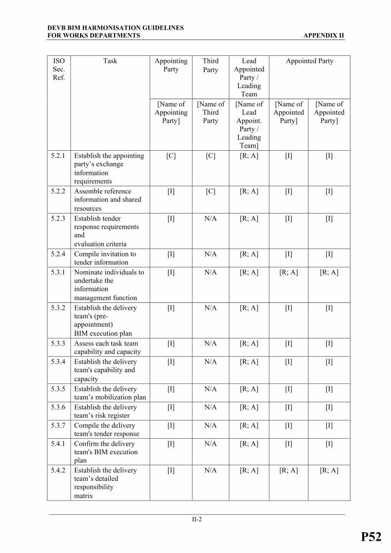
DEVB BIM HARMONISATION GUIDELINES FOR WORKS DEPARTMENTS APPENDIX II
II-2
ISO Sec. Ref.
Task Appointing Party
Third Party
Lead Appointed
Party / Leading
Team
Appointed Party
[Name of Appointing
Party]
[Name of Third Party
[Name of Lead
Appoint. Party /
Leading Team]
[Name of Appointed
Party]
[Name of Appointed
Party]
5.2.1 Establish the appointing party’s exchange information requirements
[C] [C] [R; A] [I] [I]
5.2.2 Assemble reference information and shared resources
[I] [C] [R; A] [I] [I]
5.2.3 Establish tender response requirements and evaluation criteria
[I] N/A [R; A] [I] [I]
5.2.4 Compile invitation to tender information
[I] N/A [R; A] [I] [I]
5.3.1 Nominate individuals to undertake the information management function
[I] N/A [R; A] [R; A] [R; A]
5.3.2 Establish the delivery team's (pre-appointment) BIM execution plan
[I] N/A [R; A] [I] [I]
5.3.3 Assess each task team capability and capacity
[I] N/A [R; A] [I] [I]
5.3.4 Establish the delivery team's capability and capacity
[I] N/A [R; A] [I] [I]
5.3.5 Establish the delivery team’s mobilization plan
[I] N/A [R; A] [I] [I]
5.3.6 Establish the delivery team’s risk register
[I] N/A [R; A] [I] [I]
5.3.7 Compile the delivery team's tender response
[I] N/A [R; A] [I] [I]
5.4.1 Confirm the delivery team's BIM execution plan
[I] N/A [R; A] [I] [I]
5.4.2 Establish the delivery team’s detailed responsibility matrix
[I] N/A [R; A] [R; A] [R; A]
P52
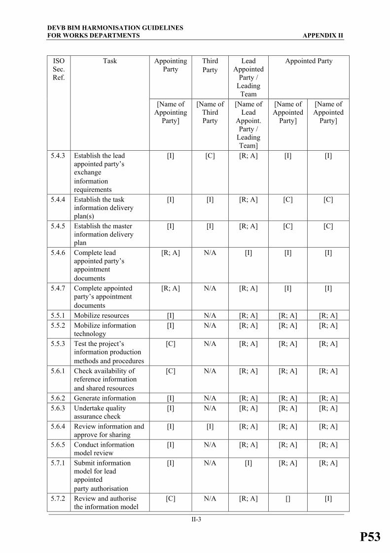
DEVB BIM HARMONISATION GUIDELINES FOR WORKS DEPARTMENTS APPENDIX II
II-3
ISO Sec. Ref.
Task Appointing Party
Third Party
Lead Appointed
Party / Leading
Team
Appointed Party
[Name of Appointing
Party]
[Name of Third Party
[Name of Lead
Appoint. Party /
Leading Team]
[Name of Appointed
Party]
[Name of Appointed
Party]
5.4.3 Establish the lead appointed party’s exchange information requirements
[I] [C] [R; A] [I] [I]
5.4.4 Establish the task information delivery plan(s)
[I] [I] [R; A] [C] [C]
5.4.5 Establish the master information delivery plan
[I] [I] [R; A] [C] [C]
5.4.6 Complete lead appointed party’s appointment documents
[R; A] N/A [I] [I] [I]
5.4.7 Complete appointed party’s appointment documents
[R; A] N/A [R; A] [I] [I]
5.5.1 Mobilize resources [I] N/A [R; A] [R; A] [R; A] 5.5.2 Mobilize information
technology [I] N/A [R; A] [R; A] [R; A]
5.5.3 Test the project’s information production methods and procedures
[C] N/A [R; A] [R; A] [R; A]
5.6.1 Check availability of reference information and shared resources
[C] N/A [R; A] [R; A] [R; A]
5.6.2 Generate information [I] N/A [R; A] [R; A] [R; A] 5.6.3 Undertake quality
assurance check [I] N/A [R; A] [R; A] [R; A]
5.6.4 Review information and approve for sharing
[I] [I] [R; A] [R; A] [R; A]
5.6.5 Conduct information model review
[I] N/A [R; A] [R; A] [R; A]
5.7.1 Submit information model for lead appointed party authorisation
[I] N/A [I] [R; A] [R; A]
5.7.2 Review and authorise the information model
[C] N/A [R; A] [] [I]
P53
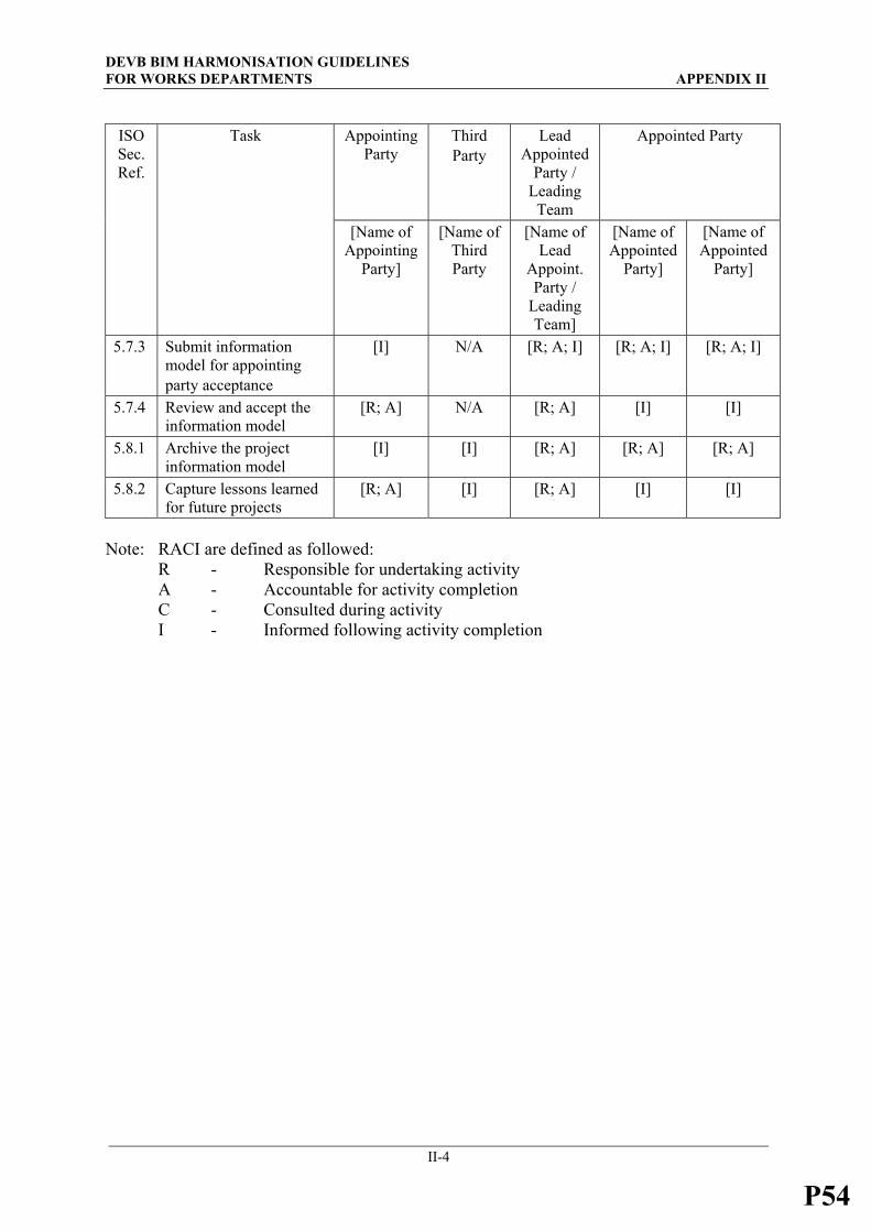
DEVB BIM HARMONISATION GUIDELINES FOR WORKS DEPARTMENTS APPENDIX II
II-4
ISO Sec. Ref.
Task Appointing Party
Third Party
Lead Appointed
Party / Leading
Team
Appointed Party
[Name of Appointing
Party]
[Name of Third Party
[Name of Lead
Appoint. Party /
Leading Team]
[Name of Appointed
Party]
[Name of Appointed
Party]
5.7.3 Submit information model for appointing party acceptance
[I] N/A [R; A; I] [R; A; I] [R; A; I]
5.7.4 Review and accept the information model
[R; A] N/A [R; A] [I] [I]
5.8.1 Archive the project information model
[I] [I] [R; A] [R; A] [R; A]
5.8.2 Capture lessons learned for future projects
[R; A] [I] [R; A] [I] [I]
Note: RACI are defined as followed:
R - Responsible for undertaking activity A - Accountable for activity completion C - Consulted during activity I - Informed following activity completion
P54

DEVB BIM HARMONISATION GUIDELINES FOR WORKS DEPARTMENTS APPENDIX III
– Data Filtering Rule Table
P55
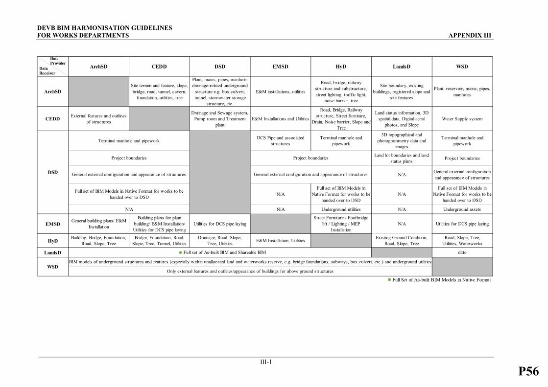
DEVB BIM HARMONISATION GUIDELINES FOR WORKS DEPARTMENTS APPENDIX III
III-1
ArchSD CEDD DSD EMSD HyD LandsD WSD
ArchSDSite terrain and feature, slope, bridge, road, tunnel, cavern,
foundation, utilities, tree
Plant, mains, pipes, manhole, drainage-related underground
structure e.g. box culvert, tunnel, stormwater storage
structure, etc.
E&M installations, utilities
Road, bridge, railway structure and substructure, street lighting, traffic light,
noise barrier, tree
Site boundary, existing buildings, registered slope and
site features
Plant, reservoir, mains, pipes, manholes
CEDDExternal features and outlines
of structures
Drainage and Sewage system, Pump room and Treatment
plantE&M Installations and Utilities
Road, Bridge, Railway structure, Street furniture,
Drain, Noise barrier, Slope and Tree
Land status information, 3D spatial data, Digital aerial
photos, and SlopeWater Supply system
DCS Pipe and associated structures
Terminal manhole and pipework
3D topographical and photogrammetry data and
images
Terminal manhole and pipework
Land lot boundaries and land status plans Project boundaries
N/A General external configuration and appearance of structures
N/AFull set of BIM Models in
Native Format for works to be handed over to DSD
N/AFull set of BIM Models in
Native Format for works to be handed over to DSD
N/A Underground utilities N/A Underground assets
EMSDGeneral building plans/ E&M
Installation
Building plans for plant building/ E&M Installation/ Utilities for DCS pipe laying
Utilities for DCS pipe layingStreet Furniture / Footbridge
lift / Lighting / MEP Installation
N/A Utilities for DCS pipe laying
HyDBuilding, Bridge, Foundation,
Road, Slope, TreeBridge, Foundation, Road,
Slope, Tree, Tunnel, UtilitiesDrainage, Road, Slope,
Tree, Utilities E&M Installation, Utilities Existing Ground Condition, Road, Slope, Tree
Road, Slope, Tree, Utilities, Waterworks
LandsD ditto
DSD
Full set of As-built BIM and Shareable BIM
Full Set of As-built BIM Models in Native Format
WSDOnly external features and outlines/appearance of buildings for above ground structures
BIM models of underground structures and features (especially within unallocated land and waterworks reserve, e.g. bridge foundations, subways, box culvert, etc.) and underground utilities
Terminal manhole and pipework
Project boundaries
General external configuration and appearance of structures
Full set of BIM Models in Native Format for works to be handed over to DSD
N/A
Project boundaries
General external configuration and appearance of structures
DataProvider
Data Receiver
P56
DEVB BIM HARMONISATION GUIDELINES FOR WORKS DEPARTMENTS APPENDIX IV
– Master Type List
Remarks: To maintain the tabular nature and for easier readability on screen, the list will
be sent by CD-ROM with the hard copy of the Guide.
The List contains with FLIP, CEDD, DSD and HyD’s codes. Due to the list is huge, it will be sent by CD-ROM with the hard copy of the Guide
P57

DEVB BIM HARMONISATION GUIDELINES FOR WORKS DEPARTMENTS APPENDIX V
– Examples of BIM Object Authoring and Importing
Civil 3D BIM Objects into BIM Models
P58
DEVB BIM HARMONISATION GUIDELINES FOR WORKS DEPARTMENTS APPENDIX V
TABLE OF CONTENTS
1. Introduction ........................................................................................................................................ V-1
2. Revit BIM Objects ............................................................................................................................. V-1 2.1. Revit Family Templates for BIM Object ............................................................................................ V-1
3. Civil 3D BIM Objects ........................................................................................................................ V-2 3.1. Name of Civil 3D Tool for BIM Object ............................................................................................. V-2 3.2. Use of Civil 3D Object Style for 2D Presentation .............................................................................. V-2
4. Insertion of Civil 3D BIM Objects into BIM Models ........................................................................ V-4 4.1. Subassemblies .................................................................................................................................... V-4 4.2. Pipes Catalog ...................................................................................................................................... V-6 4.3. Pressure Pipes Catalog ....................................................................................................................... V-8
List of Tables
Table 2-1 Revit Family Template to be Used for the Types of BIM Objects ..................................................... V-1
Table 3-1 Civil 3D Tools to be Used for the Types of BIM Objects .................................................................. V-2
List of Figures
Figure 3-1 Setting of Structure Style for 2D Symbol ......................................................................................... V-3
Figure 3-2 Setting of Component Display .......................................................................................................... V-3
Figure 4-1 “Import Subassemblies” Panel .......................................................................................................... V-4
Figure 4-2 Input Source File for “Import Subassemblies” ................................................................................. V-4
Figure 4-3 "Tool Palettes" Panel ........................................................................................................................ V-5
Figure 4-4 Files for "Pipes Catalog" ................................................................................................................... V-6
Figure 4-5 Set "Pipe Network Catalog" .............................................................................................................. V-6
Figure 4-6 Pipe Network Catalog Settings ......................................................................................................... V-7
Figure 4-7 Edit Network Parts List ..................................................................................................................... V-7
Figure 4-8 Properties of Part Size Creator .......................................................................................................... V-8
Figure 4-9 Default Catalog ................................................................................................................................. V-8
Figure 4-10 Each Folder stored with below Two Folders .................................................................................. V-8
Figure 4-11 Default Names of the Drawings in the DWG Folder ...................................................................... V-9
Figure 4-12 Images in IMG Folder ..................................................................................................................... V-9
Figure 4-13 Panel of “Content Catalog Editor” ................................................................................................ V-24
Figure 4-14 Configure General Information for Importing a Part .................................................................... V-24
Figure 4-15 Configure Part Type Information .................................................................................................. V-25
Figure 4-16 Configure Model Properties .......................................................................................................... V-26
Figure 4-17 Review and Update Connection Point Information ...................................................................... V-27
Figure 4-18 Save the Content Catalog file ........................................................................................................ V-28
P59
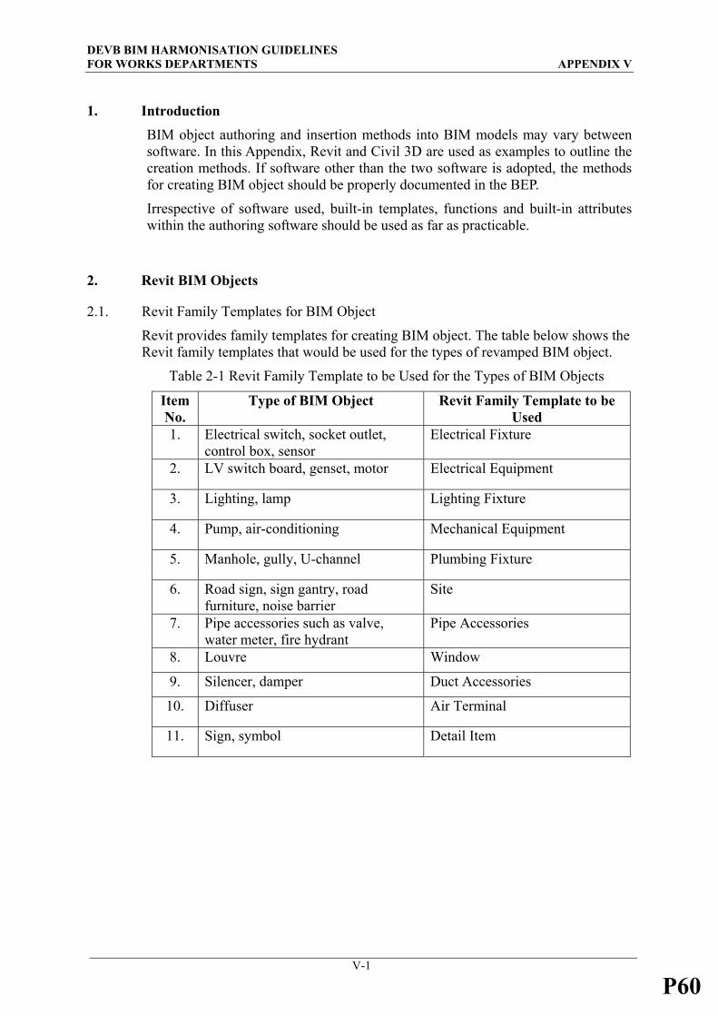
DEVB BIM HARMONISATION GUIDELINES FOR WORKS DEPARTMENTS APPENDIX V
V-1
1. Introduction
BIM object authoring and insertion methods into BIM models may vary between software. In this Appendix, Revit and Civil 3D are used as examples to outline the creation methods. If software other than the two software is adopted, the methods for creating BIM object should be properly documented in the BEP. Irrespective of software used, built-in templates, functions and built-in attributes within the authoring software should be used as far as practicable.
2. Revit BIM Objects
2.1. Revit Family Templates for BIM Object Revit provides family templates for creating BIM object. The table below shows the Revit family templates that would be used for the types of revamped BIM object.
Table 2-1 Revit Family Template to be Used for the Types of BIM Objects
Item No.
Type of BIM Object Revit Family Template to be Used
1. Electrical switch, socket outlet, control box, sensor
Electrical Fixture
2. LV switch board, genset, motor Electrical Equipment
3. Lighting, lamp Lighting Fixture
4. Pump, air-conditioning Mechanical Equipment
5. Manhole, gully, U-channel Plumbing Fixture
6. Road sign, sign gantry, road furniture, noise barrier
Site
7. Pipe accessories such as valve, water meter, fire hydrant
Pipe Accessories
8. Louvre Window
9. Silencer, damper Duct Accessories
10. Diffuser Air Terminal
11. Sign, symbol Detail Item
P60
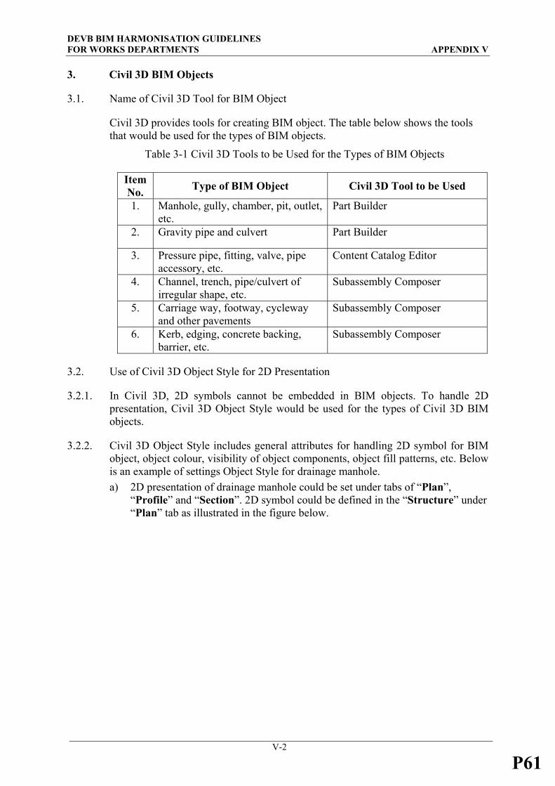
DEVB BIM HARMONISATION GUIDELINES FOR WORKS DEPARTMENTS APPENDIX V
V-2
3. Civil 3D BIM Objects
3.1. Name of Civil 3D Tool for BIM Object
Civil 3D provides tools for creating BIM object. The table below shows the tools that would be used for the types of BIM objects.
Table 3-1 Civil 3D Tools to be Used for the Types of BIM Objects
Item No.
Type of BIM Object Civil 3D Tool to be Used
1. Manhole, gully, chamber, pit, outlet, etc.
Part Builder
2. Gravity pipe and culvert Part Builder
3. Pressure pipe, fitting, valve, pipe accessory, etc.
Content Catalog Editor
4. Channel, trench, pipe/culvert of irregular shape, etc.
Subassembly Composer
5. Carriage way, footway, cycleway and other pavements
Subassembly Composer
6. Kerb, edging, concrete backing, barrier, etc.
Subassembly Composer
3.2. Use of Civil 3D Object Style for 2D Presentation
3.2.1. In Civil 3D, 2D symbols cannot be embedded in BIM objects. To handle 2D presentation, Civil 3D Object Style would be used for the types of Civil 3D BIM objects.
3.2.2. Civil 3D Object Style includes general attributes for handling 2D symbol for BIM object, object colour, visibility of object components, object fill patterns, etc. Below is an example of settings Object Style for drainage manhole. a) 2D presentation of drainage manhole could be set under tabs of “Plan”,
“Profile” and “Section”. 2D symbol could be defined in the “Structure” under “Plan” tab as illustrated in the figure below.
P61
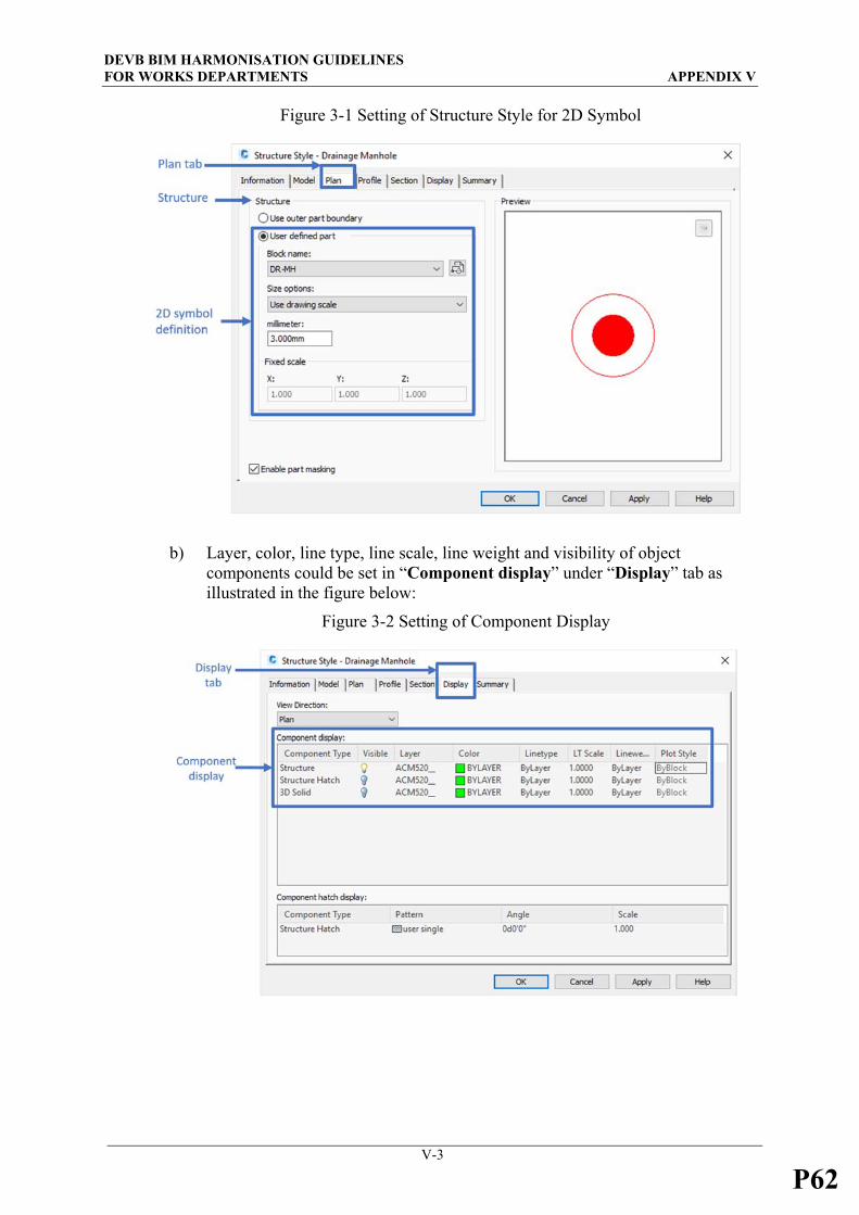
DEVB BIM HARMONISATION GUIDELINES FOR WORKS DEPARTMENTS APPENDIX V
V-3
Figure 3-1 Setting of Structure Style for 2D Symbol
b) Layer, color, line type, line scale, line weight and visibility of object components could be set in “Component display” under “Display” tab as illustrated in the figure below:
Figure 3-2 Setting of Component Display
P62
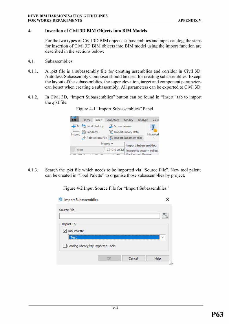
DEVB BIM HARMONISATION GUIDELINES FOR WORKS DEPARTMENTS APPENDIX V
V-4
4. Insertion of Civil 3D BIM Objects into BIM Models
For the two types of Civil 3D BIM objects, subassemblies and pipes catalog, the steps for insertion of Civil 3D BIM objects into BIM model using the import function are described in the sections below.
4.1. Subassemblies
4.1.1. A .pkt file is a subassembly file for creating assemblies and corridor in Civil 3D. Autodesk Subassembly Composer should be used for creating subassemblies. Except the layout of the subassemblies, the super elevation, target and component parameters can be set when creating a subassembly. All parameters can be exported to Civil 3D.
4.1.2. In Civil 3D, “Import Subassemblies” button can be found in “Insert” tab to import the .pkt file.
Figure 4-1 “Import Subassemblies” Panel
4.1.3. Search the .pkt file which needs to be imported via “Source File”. New tool palette can be created in “Tool Palette” to organise those subassemblies by project.
. Figure 4-2 Input Source File for “Import Subassemblies”
\
P63
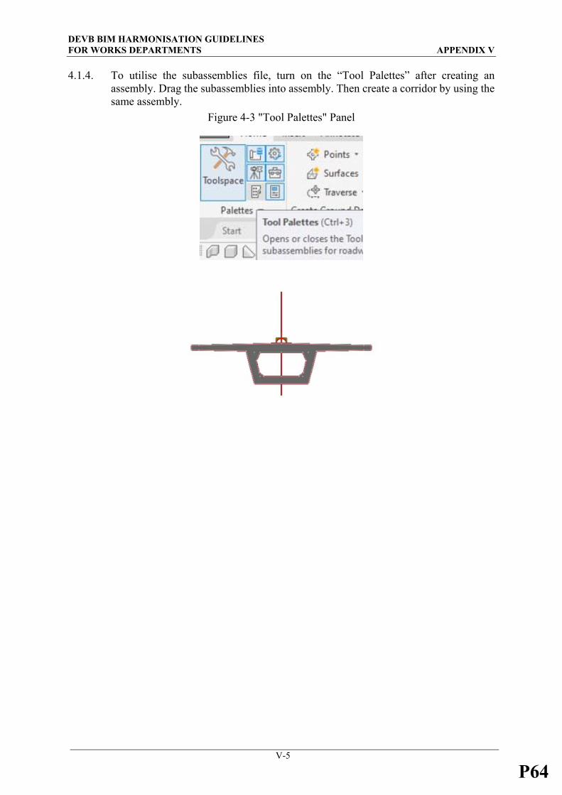
DEVB BIM HARMONISATION GUIDELINES FOR WORKS DEPARTMENTS APPENDIX V
V-5
4.1.4. To utilise the subassemblies file, turn on the “Tool Palettes” after creating an assembly. Drag the subassemblies into assembly. Then create a corridor by using the same assembly.
Figure 4-3 "Tool Palettes" Panel
P64
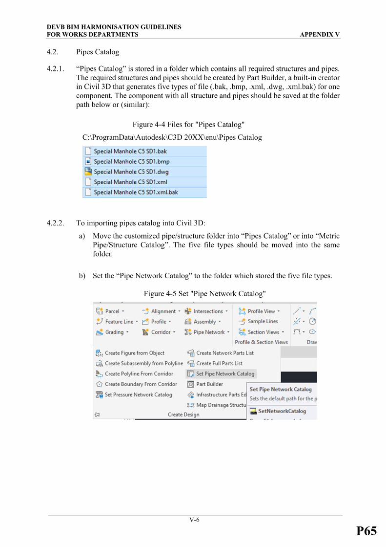
DEVB BIM HARMONISATION GUIDELINES FOR WORKS DEPARTMENTS APPENDIX V
V-6
4.2. Pipes Catalog
4.2.1. “Pipes Catalog” is stored in a folder which contains all required structures and pipes. The required structures and pipes should be created by Part Builder, a built-in creator in Civil 3D that generates five types of file (.bak, .bmp, .xml, .dwg, .xml.bak) for one component. The component with all structure and pipes should be saved at the folder path below or (similar):
Figure 4-4 Files for "Pipes Catalog"
C:\ProgramData\Autodesk\C3D 20XX\enu\Pipes Catalog
4.2.2. To importing pipes catalog into Civil 3D: a) Move the customized pipe/structure folder into “Pipes Catalog” or into “Metric
Pipe/Structure Catalog”. The five file types should be moved into the same folder.
b) Set the “Pipe Network Catalog” to the folder which stored the five file types.
Figure 4-5 Set "Pipe Network Catalog"
P65
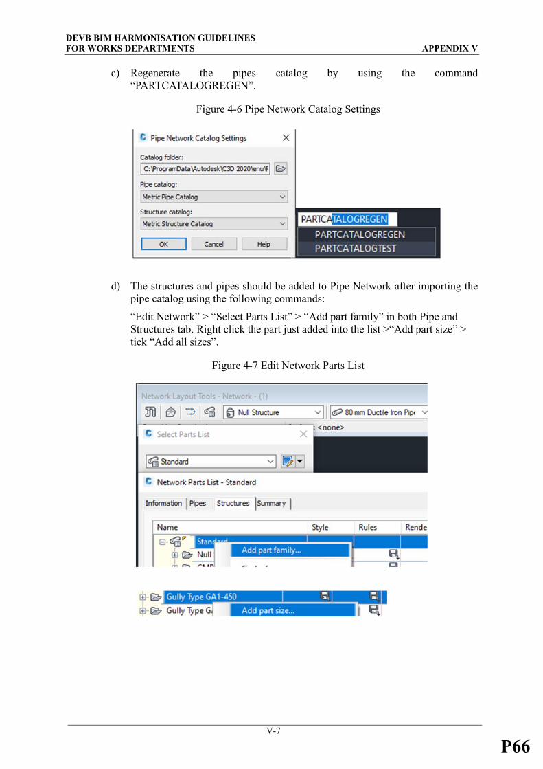
DEVB BIM HARMONISATION GUIDELINES FOR WORKS DEPARTMENTS APPENDIX V
V-7
c) Regenerate the pipes catalog by using the command “PARTCATALOGREGEN”.
Figure 4-6 Pipe Network Catalog Settings
d) The structures and pipes should be added to Pipe Network after importing the
pipe catalog using the following commands: “Edit Network” > “Select Parts List” > “Add part family” in both Pipe and Structures tab. Right click the part just added into the list >“Add part size” > tick “Add all sizes”.
Figure 4-7 Edit Network Parts List
P66
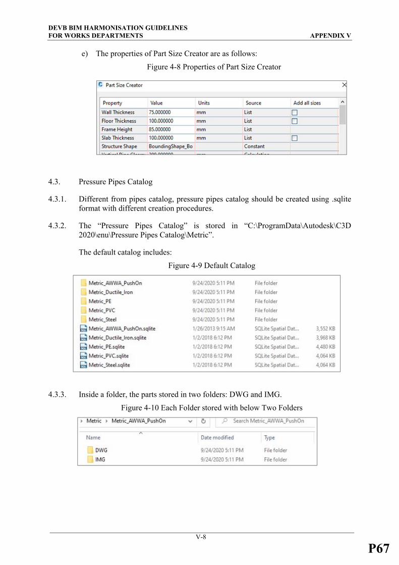
DEVB BIM HARMONISATION GUIDELINES FOR WORKS DEPARTMENTS APPENDIX V
V-8
e) The properties of Part Size Creator are as follows: Figure 4-8 Properties of Part Size Creator
4.3. Pressure Pipes Catalog
4.3.1. Different from pipes catalog, pressure pipes catalog should be created using .sqlite format with different creation procedures.
4.3.2. The “Pressure Pipes Catalog” is stored in “C:\ProgramData\Autodesk\C3D 2020\enu\Pressure Pipes Catalog\Metric”.
The default catalog includes: Figure 4-9 Default Catalog
4.3.3. Inside a folder, the parts stored in two folders: DWG and IMG. Figure 4-10 Each Folder stored with below Two Folders
P67
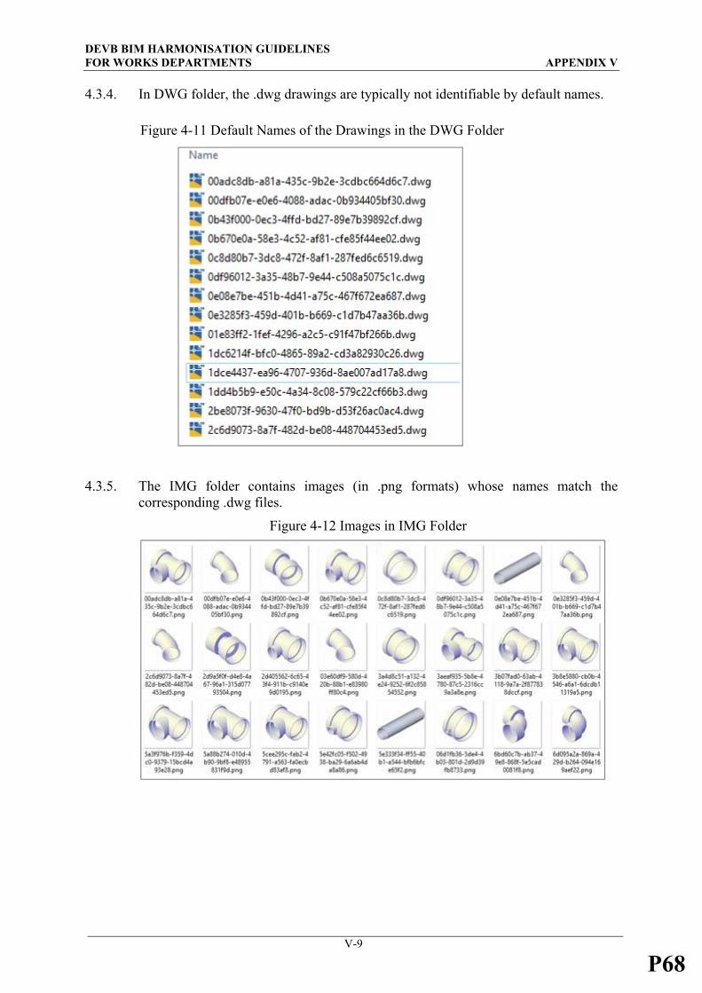
DEVB BIM HARMONISATION GUIDELINES FOR WORKS DEPARTMENTS APPENDIX V
V-9
4.3.4. In DWG folder, the .dwg drawings are typically not identifiable by default names.
Figure 4-11 Default Names of the Drawings in the DWG Folder
4.3.5. The IMG folder contains images (in .png formats) whose names match the corresponding .dwg files.
Figure 4-12 Images in IMG Folder
P68
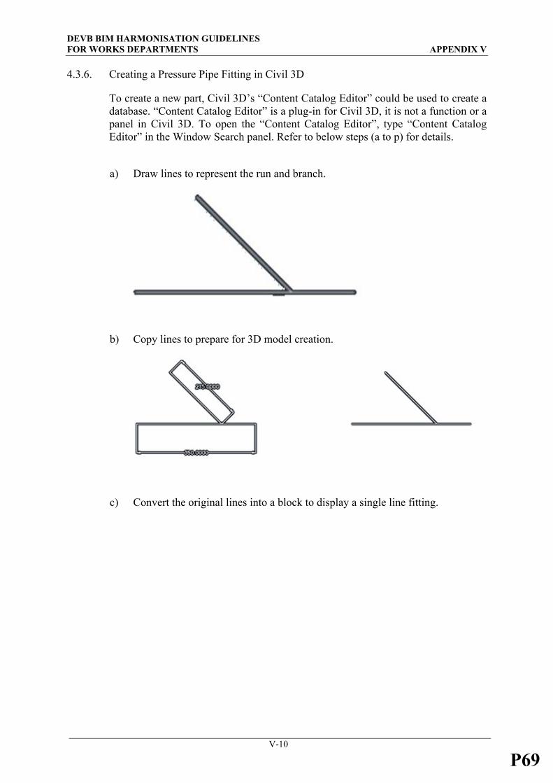
DEVB BIM HARMONISATION GUIDELINES FOR WORKS DEPARTMENTS APPENDIX V
V-10
4.3.6. Creating a Pressure Pipe Fitting in Civil 3D
To create a new part, Civil 3D’s “Content Catalog Editor” could be used to create a database. “Content Catalog Editor” is a plug-in for Civil 3D, it is not a function or a panel in Civil 3D. To open the “Content Catalog Editor”, type “Content Catalog Editor” in the Window Search panel. Refer to below steps (a to p) for details.
a) Draw lines to represent the run and branch.
b) Copy lines to prepare for 3D model creation.
c) Convert the original lines into a block to display a single line fitting.
P69
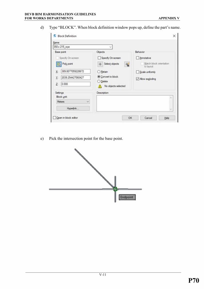
DEVB BIM HARMONISATION GUIDELINES FOR WORKS DEPARTMENTS APPENDIX V
V-11
d) Type “BLOCK”. When block definition window pops up, define the part’s name.
e) Pick the intersection point for the base point.
P70
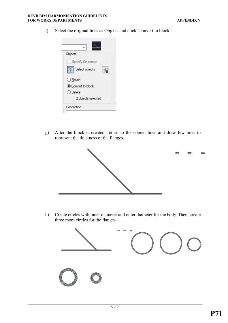
DEVB BIM HARMONISATION GUIDELINES FOR WORKS DEPARTMENTS APPENDIX V
V-12
f) Select the original lines as Objects and click “convert to block”.
g) After the block is created, return to the copied lines and draw few lines to represent the thickness of the flanges.
h) Create circles with inner diameter and outer diameter for the body. Then, create three more circles for the flanges.
P71
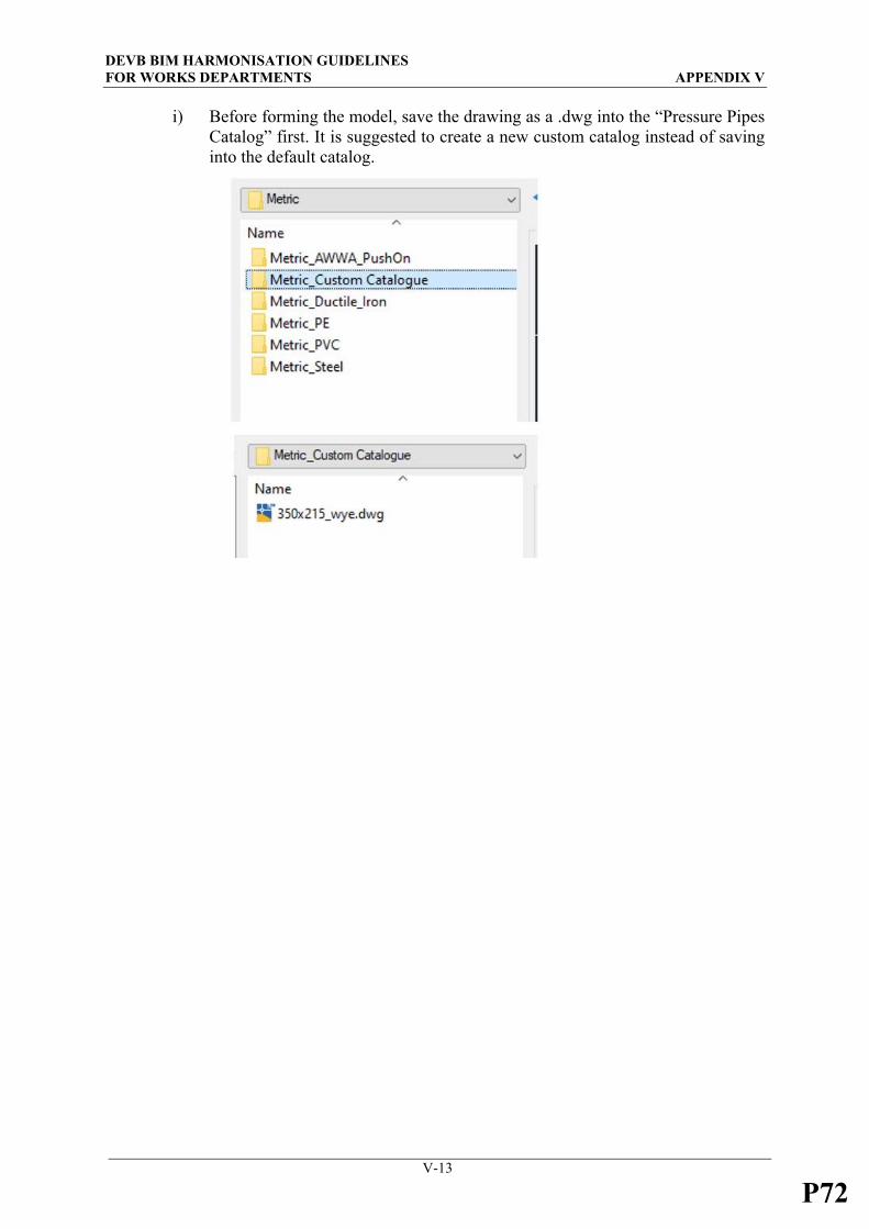
DEVB BIM HARMONISATION GUIDELINES FOR WORKS DEPARTMENTS APPENDIX V
V-13
i) Before forming the model, save the drawing as a .dwg into the “Pressure Pipes Catalog” first. It is suggested to create a new custom catalog instead of saving into the default catalog.
P72
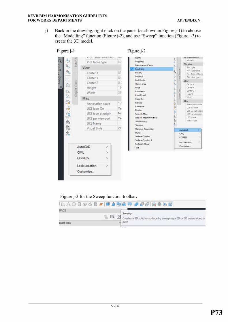
DEVB BIM HARMONISATION GUIDELINES FOR WORKS DEPARTMENTS APPENDIX V
V-14
j) Back in the drawing, right click on the panel (as shown in Figure j-1) to choose the “Modelling” function (Figure j-2), and use “Sweep” function (Figure j-3) to create the 3D model.
Figure j-1
Figure j-2
Figure j-3 for the Sweep function toolbar:
P73
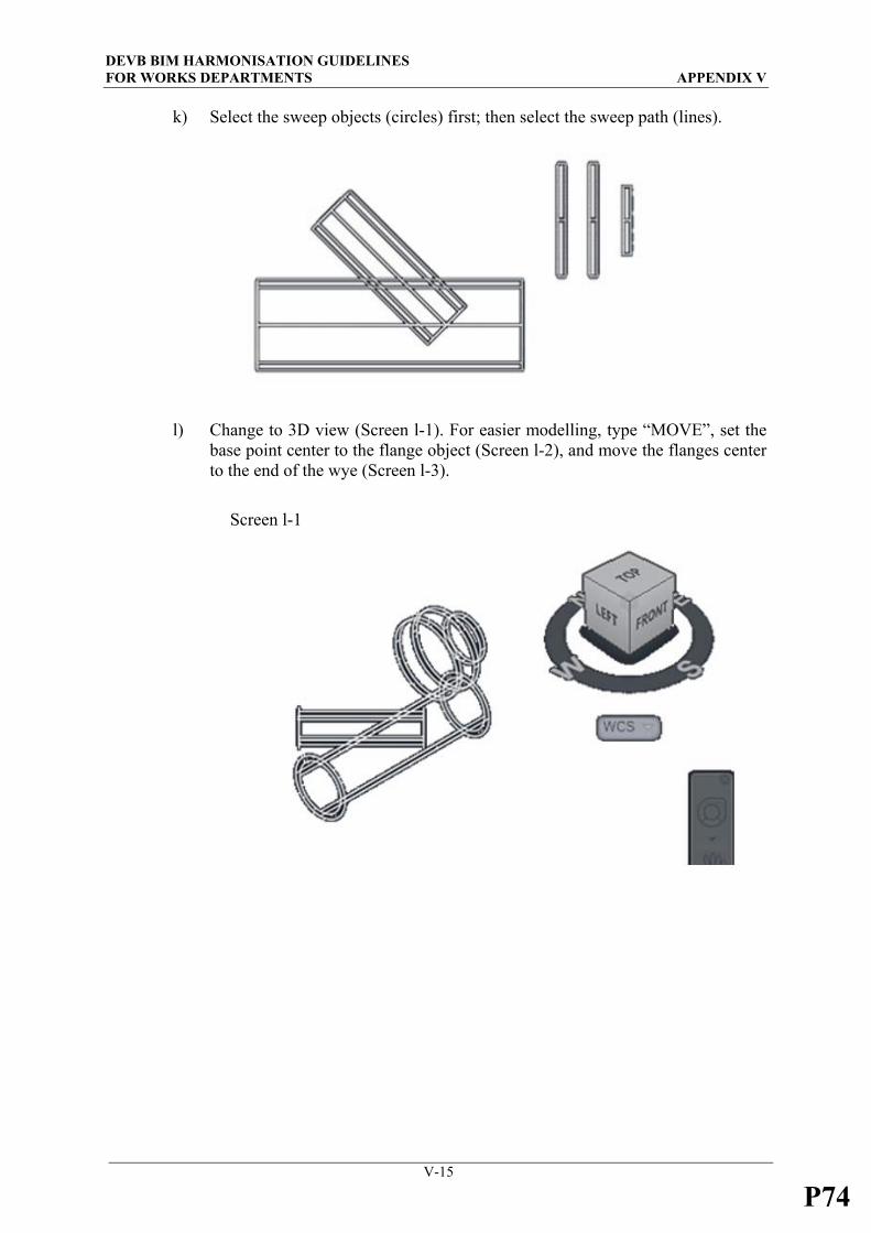
DEVB BIM HARMONISATION GUIDELINES FOR WORKS DEPARTMENTS APPENDIX V
V-15
k) Select the sweep objects (circles) first; then select the sweep path (lines).
l) Change to 3D view (Screen l-1). For easier modelling, type “MOVE”, set the base point center to the flange object (Screen l-2), and move the flanges center to the end of the wye (Screen l-3).
Screen l-1
P74
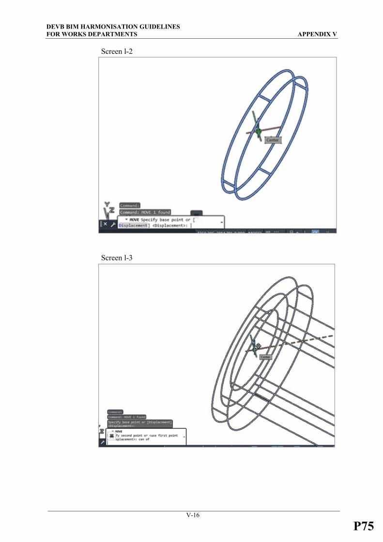
DEVB BIM HARMONISATION GUIDELINES FOR WORKS DEPARTMENTS APPENDIX V
V-16
Screen l-2
Screen l-3
P75
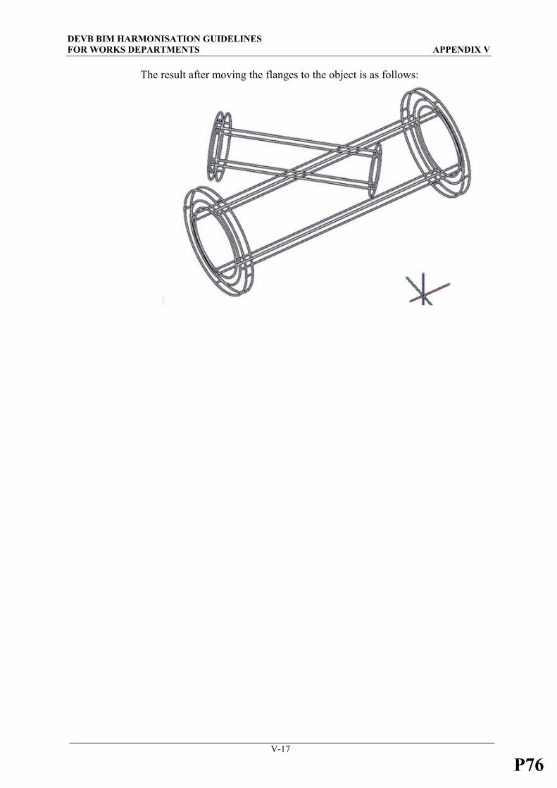
DEVB BIM HARMONISATION GUIDELINES FOR WORKS DEPARTMENTS APPENDIX V
V-17
The result after moving the flanges to the object is as follows:
P76
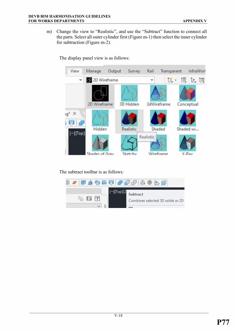
DEVB BIM HARMONISATION GUIDELINES FOR WORKS DEPARTMENTS APPENDIX V
V-18
m) Change the view to “Realistic”, and use the “Subtract” function to connect all the parts. Select all outer cylinder first (Figure m-1) then select the inner cylinder for subtraction (Figure m-2).
The display panel view is as follows:
The subtract toolbar is as follows:
P77
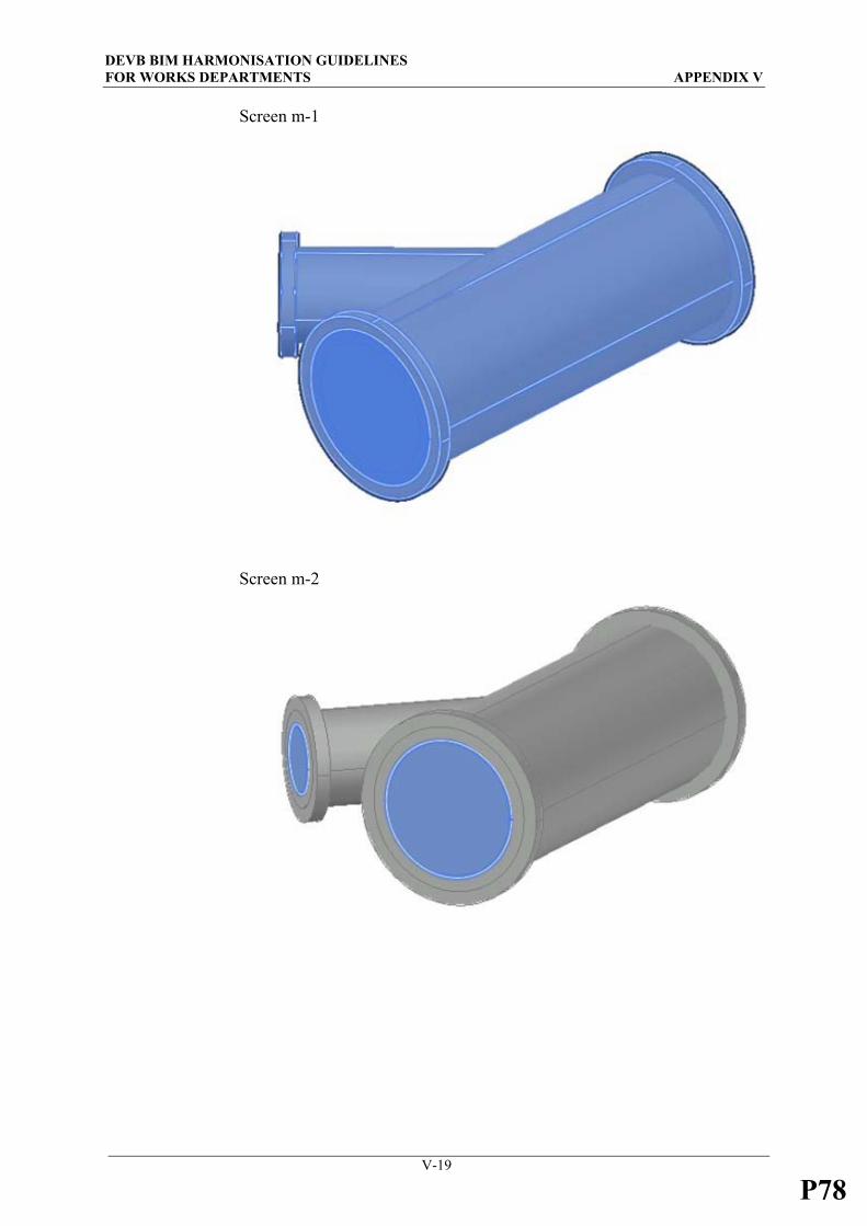
DEVB BIM HARMONISATION GUIDELINES FOR WORKS DEPARTMENTS APPENDIX V
V-19
Screen m-1
Screen m-2
P78

DEVB BIM HARMONISATION GUIDELINES FOR WORKS DEPARTMENTS APPENDIX V
V-20
The result after subtracting the inner cylinder is as follows: Realistic:
Wireframe:
P79
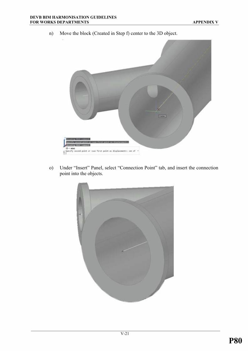
DEVB BIM HARMONISATION GUIDELINES FOR WORKS DEPARTMENTS APPENDIX V
V-21
n) Move the block (Created in Step f) center to the 3D object.
o) Under “Insert” Panel, select “Connection Point” tab, and insert the connection point into the objects.
P80
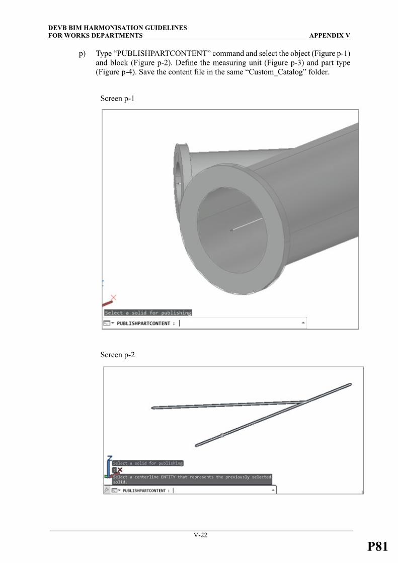
DEVB BIM HARMONISATION GUIDELINES FOR WORKS DEPARTMENTS APPENDIX V
V-22
p) Type “PUBLISHPARTCONTENT” command and select the object (Figure p-1) and block (Figure p-2). Define the measuring unit (Figure p-3) and part type (Figure p-4). Save the content file in the same “Custom_Catalog” folder.
Screen p-1
Screen p-2
P81
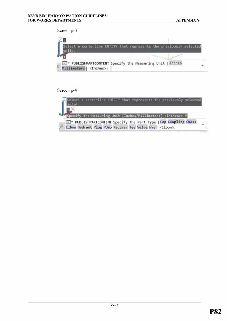
DEVB BIM HARMONISATION GUIDELINES FOR WORKS DEPARTMENTS APPENDIX V
V-23
Screen p-3
Screen p-4
P82
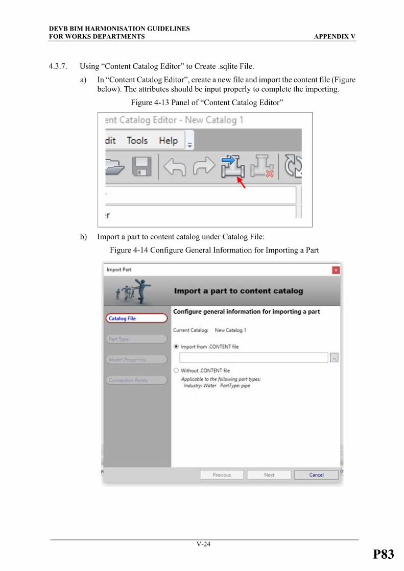
DEVB BIM HARMONISATION GUIDELINES FOR WORKS DEPARTMENTS APPENDIX V
V-24
4.3.7. Using “Content Catalog Editor” to Create .sqlite File. a) In “Content Catalog Editor”, create a new file and import the content file (Figure
below). The attributes should be input properly to complete the importing. Figure 4-13 Panel of “Content Catalog Editor”
b) Import a part to content catalog under Catalog File:
Figure 4-14 Configure General Information for Importing a Part
P83
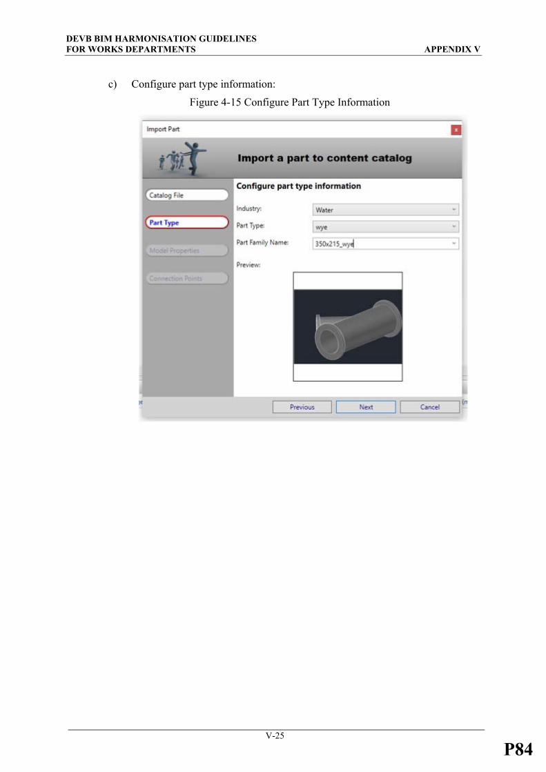
DEVB BIM HARMONISATION GUIDELINES FOR WORKS DEPARTMENTS APPENDIX V
V-25
c) Configure part type information: Figure 4-15 Configure Part Type Information
P84
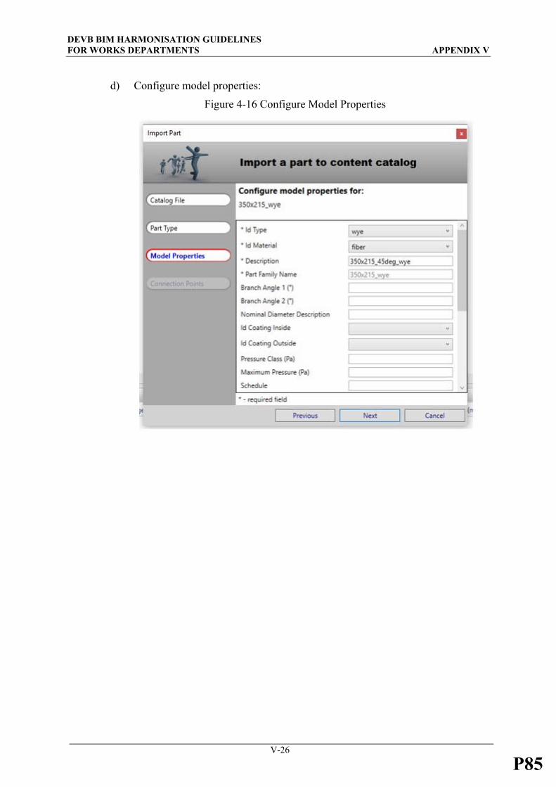
DEVB BIM HARMONISATION GUIDELINES FOR WORKS DEPARTMENTS APPENDIX V
V-26
d) Configure model properties: Figure 4-16 Configure Model Properties
P85
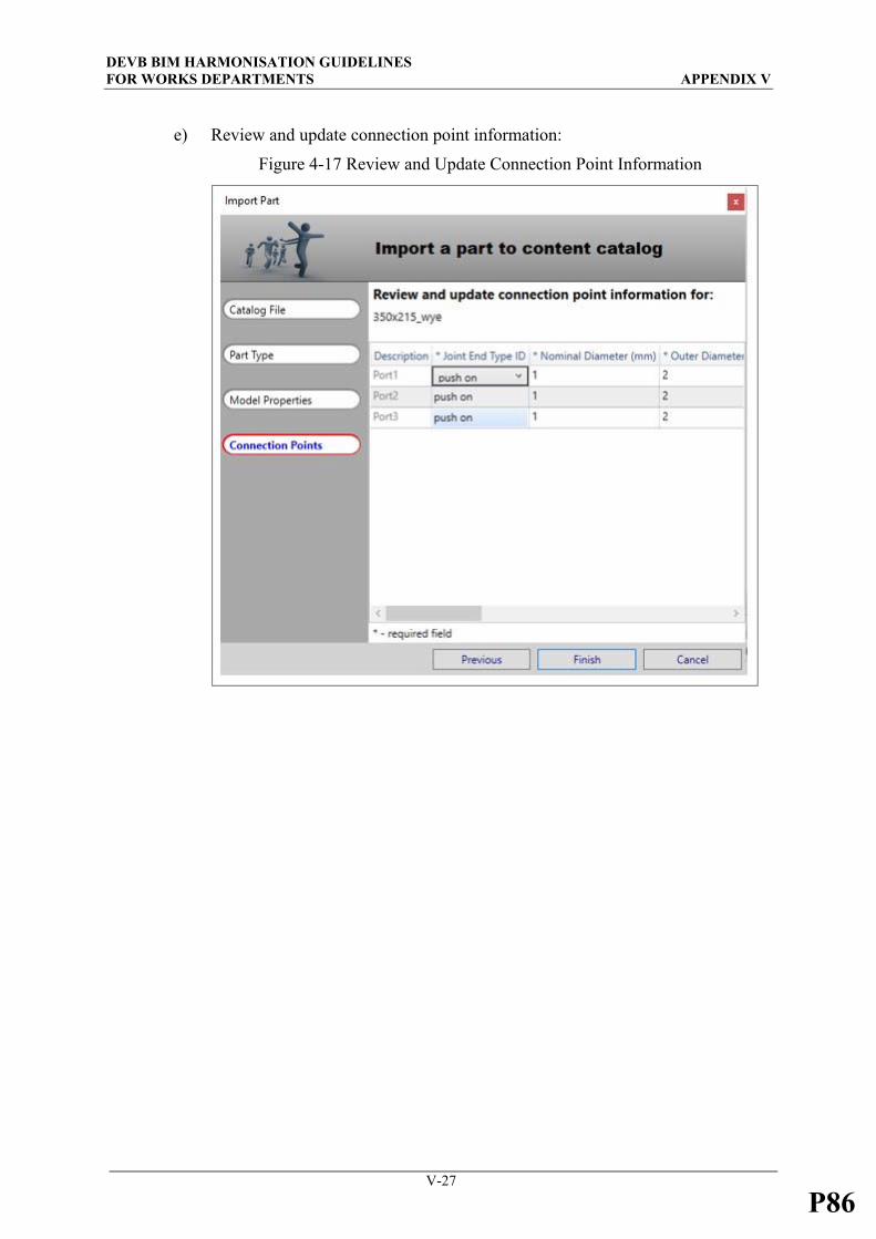
DEVB BIM HARMONISATION GUIDELINES FOR WORKS DEPARTMENTS APPENDIX V
V-27
e) Review and update connection point information: Figure 4-17 Review and Update Connection Point Information
P86
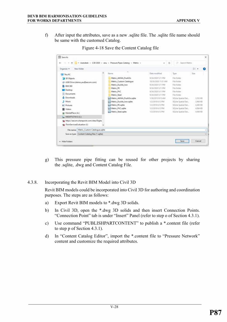
DEVB BIM HARMONISATION GUIDELINES FOR WORKS DEPARTMENTS APPENDIX V
V-28
f) After input the attributes, save as a new .sqlite file. The .sqlite file name should be same with the customed Catalog.
Figure 4-18 Save the Content Catalog file
g) This pressure pipe fitting can be reused for other projects by sharing the .sqlite, .dwg and Content Catalog File.
4.3.8. Incorporating the Revit BIM Model into Civil 3D Revit BIM models could be incorporated into Civil 3D for authoring and coordination purposes. The steps are as follows: a) Export Revit BIM models to *.dwg 3D solids. b) In Civil 3D, open the *.dwg 3D solids and then insert Connection Points.
“Connection Point” tab is under “Insert” Panel (refer to step o of Section 4.3.1). c) Use command “PUBLISHPARTCONTENT” to publish a *.content file (refer
to step p of Section 4.3.1). d) In “Content Catalog Editor”, import the *.content file to “Pressure Network”
content and customize the required attributes.
P87

DEVB BIM HARMONISATION GUIDELINES FOR WORKS DEPARTMENTS APPENDIX VI
– LOD-I Requirements, Creation and Extraction
P88
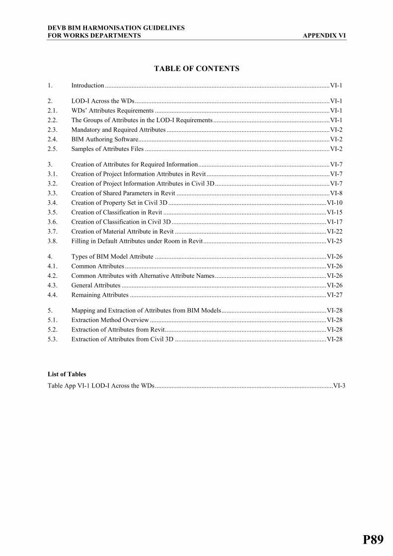
DEVB BIM HARMONISATION GUIDELINES FOR WORKS DEPARTMENTS APPENDIX VI
TABLE OF CONTENTS
1. Introduction ....................................................................................................................................... VI-1
2. LOD-I Across the WDs ..................................................................................................................... VI-1 2.1. WDs’ Attributes Requirements ......................................................................................................... VI-1 2.2. The Groups of Attributes in the LOD-I Requirements ...................................................................... VI-1 2.3. Mandatory and Required Attributes .................................................................................................. VI-2 2.4. BIM Authoring Software ................................................................................................................... VI-2 2.5. Samples of Attributes Files ............................................................................................................... VI-2
3. Creation of Attributes for Required Information ............................................................................... VI-7 3.1. Creation of Project Information Attributes in Revit .......................................................................... VI-7 3.2. Creation of Project Information Attributes in Civil 3D ..................................................................... VI-7 3.3. Creation of Shared Parameters in Revit ............................................................................................ VI-8 3.4. Creation of Property Set in Civil 3D ............................................................................................... VI-10 3.5. Creation of Classification in Revit .................................................................................................. VI-15 3.6. Creation of Classification in Civil 3D ............................................................................................. VI-17 3.7. Creation of Material Attribute in Revit ........................................................................................... VI-22 3.8. Filling in Default Attributes under Room in Revit .......................................................................... VI-25
4. Types of BIM Model Attribute ....................................................................................................... VI-26 4.1. Common Attributes ......................................................................................................................... VI-26 4.2. Common Attributes with Alternative Attribute Names ................................................................... VI-26 4.3. General Attributes ........................................................................................................................... VI-26 4.4. Remaining Attributes ...................................................................................................................... VI-27
5. Mapping and Extraction of Attributes from BIM Models ............................................................... VI-28 5.1. Extraction Method Overview .......................................................................................................... VI-28 5.2. Extraction of Attributes from Revit ................................................................................................. VI-28 5.3. Extraction of Attributes from Civil 3D ........................................................................................... VI-28
List of Tables
Table App VI-1 LOD-I Across the WDs ........................................................................................................... VI-3
P89
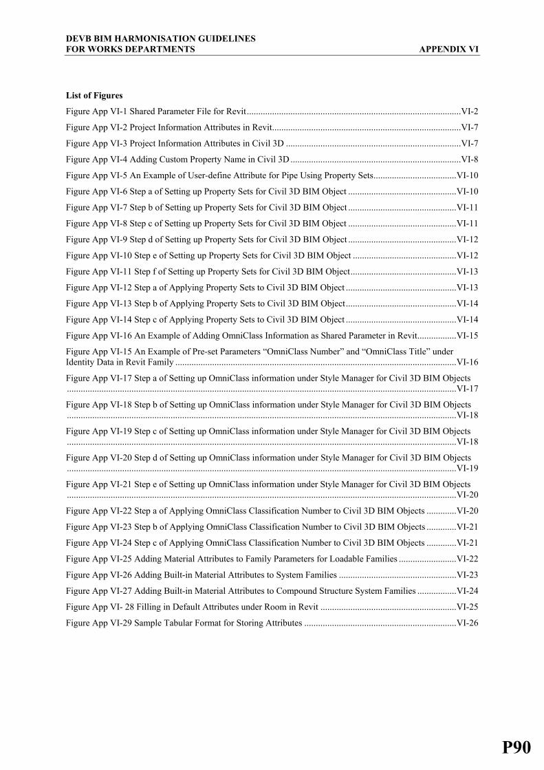
DEVB BIM HARMONISATION GUIDELINES FOR WORKS DEPARTMENTS APPENDIX VI
List of Figures
Figure App VI-1 Shared Parameter File for Revit ............................................................................................. VI-2
Figure App VI-2 Project Information Attributes in Revit .................................................................................. VI-7
Figure App VI-3 Project Information Attributes in Civil 3D ............................................................................ VI-7
Figure App VI-4 Adding Custom Property Name in Civil 3D .......................................................................... VI-8
Figure App VI-5 An Example of User-define Attribute for Pipe Using Property Sets .................................... VI-10
Figure App VI-6 Step a of Setting up Property Sets for Civil 3D BIM Object ............................................... VI-10
Figure App VI-7 Step b of Setting up Property Sets for Civil 3D BIM Object ............................................... VI-11
Figure App VI-8 Step c of Setting up Property Sets for Civil 3D BIM Object ............................................... VI-11
Figure App VI-9 Step d of Setting up Property Sets for Civil 3D BIM Object ............................................... VI-12
Figure App VI-10 Step e of Setting up Property Sets for Civil 3D BIM Object ............................................. VI-12
Figure App VI-11 Step f of Setting up Property Sets for Civil 3D BIM Object .............................................. VI-13
Figure App VI-12 Step a of Applying Property Sets to Civil 3D BIM Object ................................................ VI-13
Figure App VI-13 Step b of Applying Property Sets to Civil 3D BIM Object ................................................ VI-14
Figure App VI-14 Step c of Applying Property Sets to Civil 3D BIM Object ................................................ VI-14
Figure App VI-16 An Example of Adding OmniClass Information as Shared Parameter in Revit ................. VI-15
Figure App VI-15 An Example of Pre-set Parameters “OmniClass Number” and “OmniClass Title” under Identity Data in Revit Family .......................................................................................................................... VI-16
Figure App VI-17 Step a of Setting up OmniClass information under Style Manager for Civil 3D BIM Objects ......................................................................................................................................................................... VI-17
Figure App VI-18 Step b of Setting up OmniClass information under Style Manager for Civil 3D BIM Objects ......................................................................................................................................................................... VI-18
Figure App VI-19 Step c of Setting up OmniClass information under Style Manager for Civil 3D BIM Objects ......................................................................................................................................................................... VI-18
Figure App VI-20 Step d of Setting up OmniClass information under Style Manager for Civil 3D BIM Objects ......................................................................................................................................................................... VI-19
Figure App VI-21 Step e of Setting up OmniClass information under Style Manager for Civil 3D BIM Objects ......................................................................................................................................................................... VI-20
Figure App VI-22 Step a of Applying OmniClass Classification Number to Civil 3D BIM Objects ............. VI-20
Figure App VI-23 Step b of Applying OmniClass Classification Number to Civil 3D BIM Objects ............. VI-21
Figure App VI-24 Step c of Applying OmniClass Classification Number to Civil 3D BIM Objects ............. VI-21
Figure App VI-25 Adding Material Attributes to Family Parameters for Loadable Families ......................... VI-22
Figure App VI-26 Adding Built-in Material Attributes to System Families ................................................... VI-23
Figure App VI-27 Adding Built-in Material Attributes to Compound Structure System Families ................. VI-24
Figure App VI- 28 Filling in Default Attributes under Room in Revit ........................................................... VI-25
Figure App VI-29 Sample Tabular Format for Storing Attributes .................................................................. VI-26
P90
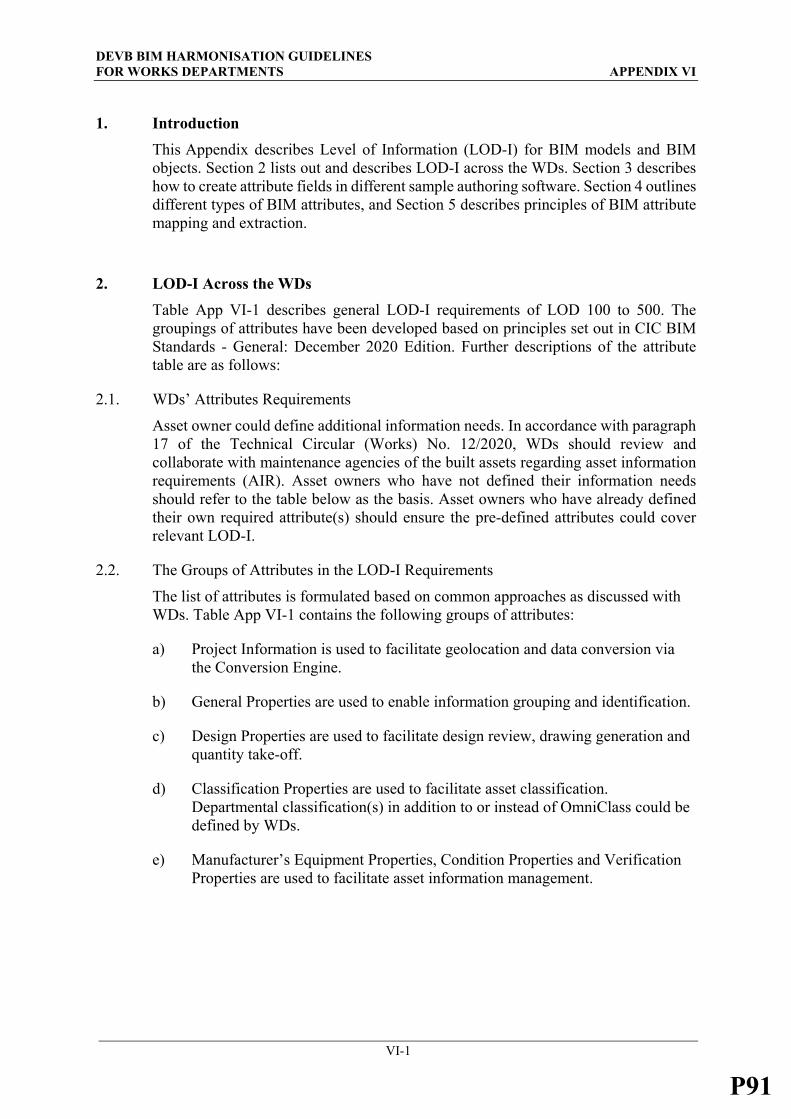
DEVB BIM HARMONISATION GUIDELINES FOR WORKS DEPARTMENTS APPENDIX VI
VI-1
1. Introduction
This Appendix describes Level of Information (LOD-I) for BIM models and BIM objects. Section 2 lists out and describes LOD-I across the WDs. Section 3 describes how to create attribute fields in different sample authoring software. Section 4 outlines different types of BIM attributes, and Section 5 describes principles of BIM attribute mapping and extraction.
2. LOD-I Across the WDs
Table App VI-1 describes general LOD-I requirements of LOD 100 to 500. The groupings of attributes have been developed based on principles set out in CIC BIM Standards - General: December 2020 Edition. Further descriptions of the attribute table are as follows:
2.1. WDs’ Attributes Requirements Asset owner could define additional information needs. In accordance with paragraph 17 of the Technical Circular (Works) No. 12/2020, WDs should review and collaborate with maintenance agencies of the built assets regarding asset information requirements (AIR). Asset owners who have not defined their information needs should refer to the table below as the basis. Asset owners who have already defined their own required attribute(s) should ensure the pre-defined attributes could cover relevant LOD-I.
2.2. The Groups of Attributes in the LOD-I Requirements The list of attributes is formulated based on common approaches as discussed with WDs. Table App VI-1 contains the following groups of attributes:
a) Project Information is used to facilitate geolocation and data conversion via the Conversion Engine.
b) General Properties are used to enable information grouping and identification.
c) Design Properties are used to facilitate design review, drawing generation and quantity take-off.
d) Classification Properties are used to facilitate asset classification. Departmental classification(s) in addition to or instead of OmniClass could be defined by WDs.
e) Manufacturer’s Equipment Properties, Condition Properties and Verification Properties are used to facilitate asset information management.
P91
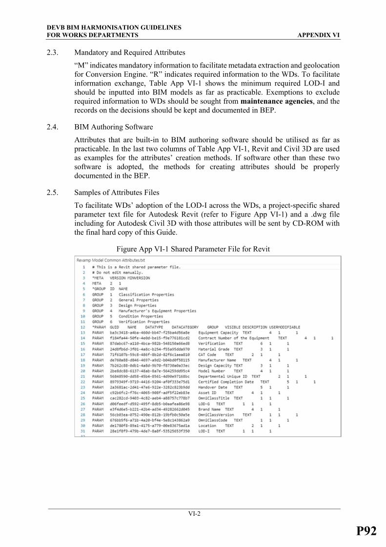
DEVB BIM HARMONISATION GUIDELINES FOR WORKS DEPARTMENTS APPENDIX VI
VI-2
2.3. Mandatory and Required Attributes “M” indicates mandatory information to facilitate metadata extraction and geolocation for Conversion Engine. “R” indicates required information to the WDs. To facilitate information exchange, Table App VI-1 shows the minimum required LOD-I and should be inputted into BIM models as far as practicable. Exemptions to exclude required information to WDs should be sought from maintenance agencies, and the records on the decisions should be kept and documented in BEP.
2.4. BIM Authoring Software Attributes that are built-in to BIM authoring software should be utilised as far as practicable. In the last two columns of Table App VI-1, Revit and Civil 3D are used as examples for the attributes’ creation methods. If software other than these two software is adopted, the methods for creating attributes should be properly documented in the BEP.
2.5. Samples of Attributes Files To facilitate WDs’ adoption of the LOD-I across the WDs, a project-specific shared parameter text file for Autodesk Revit (refer to Figure App VI-1) and a .dwg file including for Autodesk Civil 3D with those attributes will be sent by CD-ROM with the final hard copy of this Guide.
Figure App VI-1 Shared Parameter File for Revit
P92
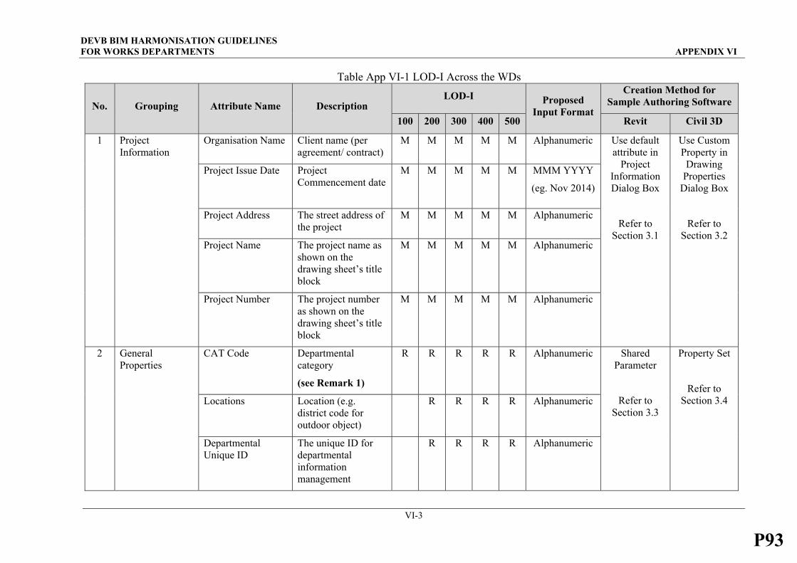
DEVB BIM HARMONISATION GUIDELINES FOR WORKS DEPARTMENTS APPENDIX VI
VI-3
Table App VI-1 LOD-I Across the WDs
No. Grouping Attribute Name Description LOD-I Proposed
Input Format
Creation Method for Sample Authoring Software
100 200 300 400 500 Revit Civil 3D
1 Project Information
Organisation Name Client name (per agreement/ contract)
M M M M M Alphanumeric Use default attribute in
Project Information Dialog Box
Refer to Section 3.1
Use Custom Property in Drawing
Properties Dialog Box
Refer to Section 3.2
Project Issue Date Project Commencement date
M M M M M MMM YYYY
(eg. Nov 2014)
Project Address The street address of the project
M M M M M Alphanumeric
Project Name The project name as shown on the drawing sheet’s title block
M M M M M Alphanumeric
Project Number The project number as shown on the drawing sheet’s title block
M M M M M Alphanumeric
2 General Properties
CAT Code Departmental category
(see Remark 1)
R R R R R Alphanumeric Shared Parameter
Refer to Section 3.3
Property Set
Refer to Section 3.4 Locations Location (e.g.
district code for outdoor object)
R R R R Alphanumeric
Departmental Unique ID
The unique ID for departmental information management
R R R R Alphanumeric
P93
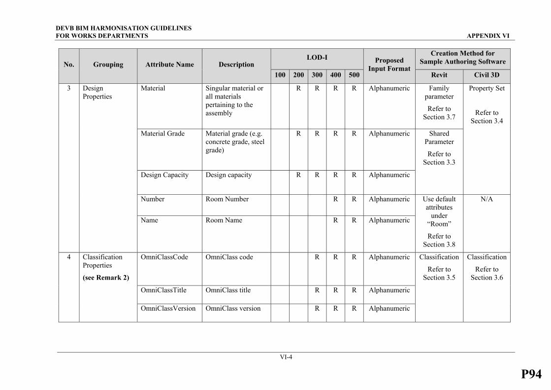
DEVB BIM HARMONISATION GUIDELINES FOR WORKS DEPARTMENTS APPENDIX VI
VI-4
No. Grouping Attribute Name Description LOD-I Proposed
Input Format
Creation Method for Sample Authoring Software
100 200 300 400 500 Revit Civil 3D
3 Design Properties
Material Singular material or all materials pertaining to the assembly
R R R R Alphanumeric Family parameter
Refer to Section 3.7
Property Set
Refer to Section 3.4
Material Grade Material grade (e.g. concrete grade, steel grade)
R R R R Alphanumeric Shared Parameter
Refer to Section 3.3
Design Capacity Design capacity R R R R Alphanumeric
Number Room Number R R Alphanumeric Use default attributes
under “Room”
Refer to Section 3.8
N/A
Name Room Name R R Alphanumeric
4 Classification Properties
(see Remark 2)
OmniClassCode OmniClass code R R R Alphanumeric Classification
Refer to Section 3.5
Classification
Refer to Section 3.6
OmniClassTitle OmniClass title R R R Alphanumeric
OmniClassVersion OmniClass version R R R Alphanumeric
P94
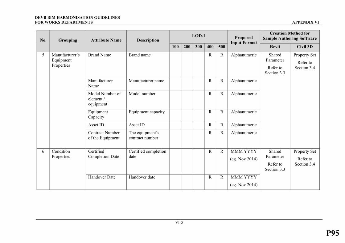
DEVB BIM HARMONISATION GUIDELINES FOR WORKS DEPARTMENTS APPENDIX VI
VI-5
No. Grouping Attribute Name Description LOD-I Proposed
Input Format
Creation Method for Sample Authoring Software
100 200 300 400 500 Revit Civil 3D
5 Manufacturer’s Equipment Properties
Brand Name Brand name R R Alphanumeric Shared Parameter
Refer to Section 3.3
Property Set
Refer to Section 3.4
Manufacturer Name
Manufacturer name R R Alphanumeric
Model Number of element / equipment
Model number R R Alphanumeric
Equipment Capacity
Equipment capacity R R Alphanumeric
Asset ID Asset ID R R Alphanumeric
Contract Number of the Equipment
The equipment’s contract number
R R Alphanumeric
6 Condition Properties
Certified Completion Date
Certified completion date
R R MMM YYYY
(eg. Nov 2014)
Shared Parameter
Refer to Section 3.3
Property Set
Refer to Section 3.4
Handover Date Handover date R R MMM YYYY
(eg. Nov 2014)
P95
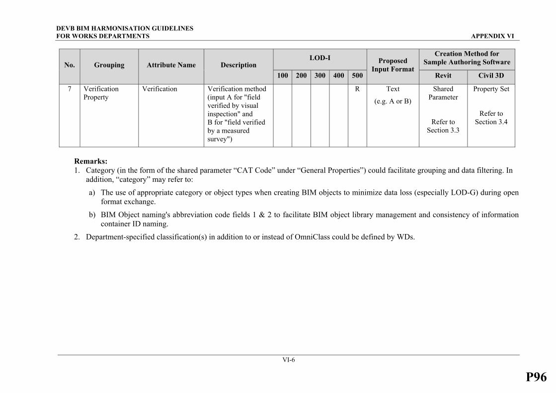
DEVB BIM HARMONISATION GUIDELINES FOR WORKS DEPARTMENTS APPENDIX VI
VI-6
No. Grouping Attribute Name Description LOD-I Proposed
Input Format
Creation Method for Sample Authoring Software
100 200 300 400 500 Revit Civil 3D
7 Verification Property
Verification Verification method (input A for "field verified by visual inspection" and B for "field verified by a measured survey")
R Text
(e.g. A or B)
Shared Parameter
Refer to Section 3.3
Property Set
Refer to Section 3.4
Remarks: 1. Category (in the form of the shared parameter “CAT Code” under “General Properties”) could facilitate grouping and data filtering. In
addition, “category” may refer to: a) The use of appropriate category or object types when creating BIM objects to minimize data loss (especially LOD-G) during open
format exchange. b) BIM Object naming's abbreviation code fields 1 & 2 to facilitate BIM object library management and consistency of information
container ID naming. 2. Department-specified classification(s) in addition to or instead of OmniClass could be defined by WDs.
P96
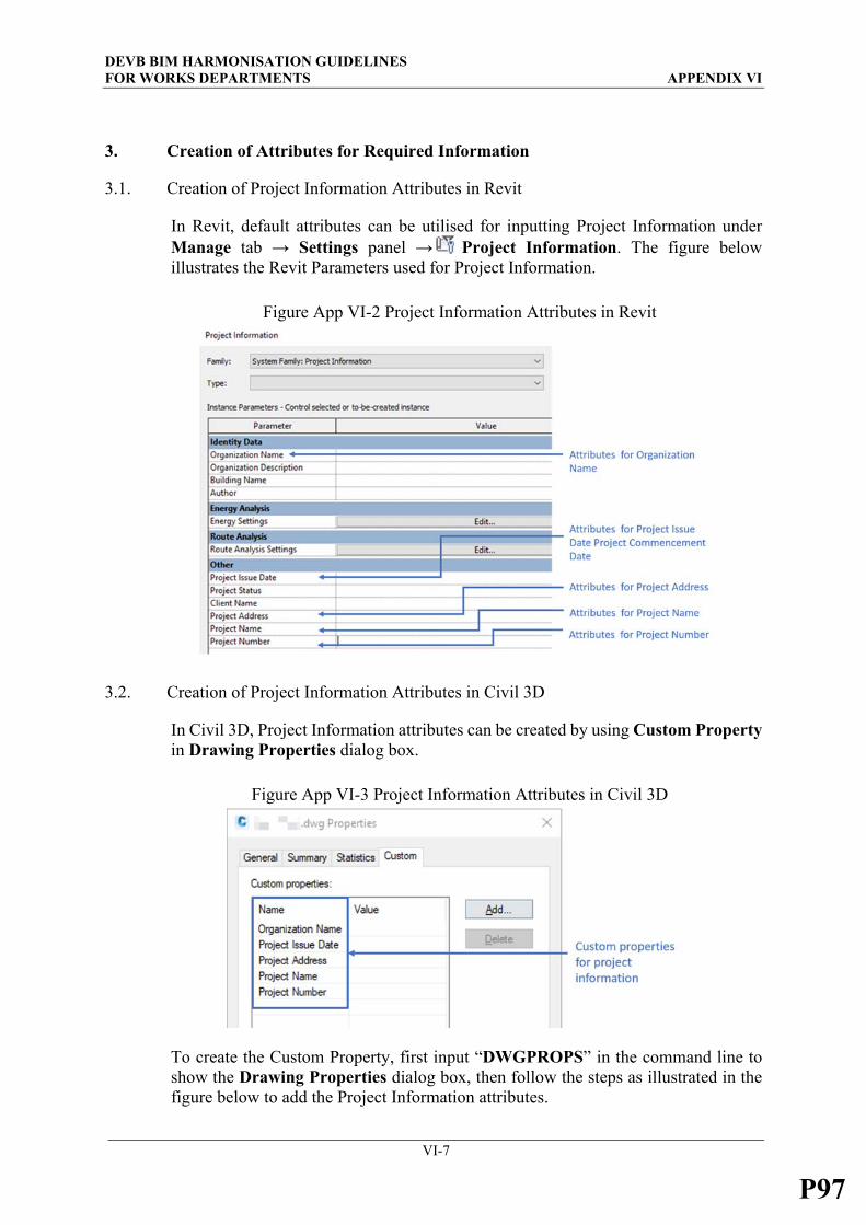
DEVB BIM HARMONISATION GUIDELINES FOR WORKS DEPARTMENTS APPENDIX VI
VI-7
3. Creation of Attributes for Required Information
3.1. Creation of Project Information Attributes in Revit
In Revit, default attributes can be utilised for inputting Project Information under Manage tab → Settings panel → Project Information. The figure below illustrates the Revit Parameters used for Project Information.
Figure App VI-2 Project Information Attributes in Revit
3.2. Creation of Project Information Attributes in Civil 3D
In Civil 3D, Project Information attributes can be created by using Custom Property in Drawing Properties dialog box.
Figure App VI-3 Project Information Attributes in Civil 3D
To create the Custom Property, first input “DWGPROPS” in the command line to show the Drawing Properties dialog box, then follow the steps as illustrated in the figure below to add the Project Information attributes.
P97
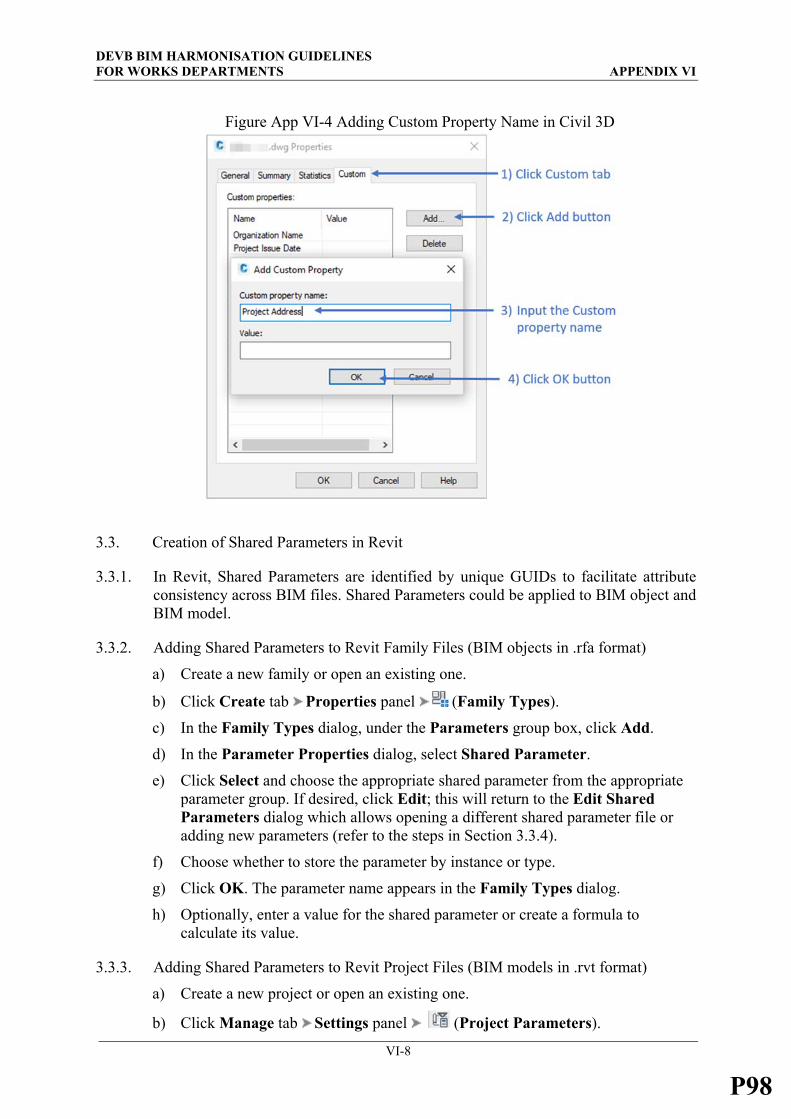
DEVB BIM HARMONISATION GUIDELINES FOR WORKS DEPARTMENTS APPENDIX VI
VI-8
Figure App VI-4 Adding Custom Property Name in Civil 3D
3.3. Creation of Shared Parameters in Revit
3.3.1. In Revit, Shared Parameters are identified by unique GUIDs to facilitate attribute consistency across BIM files. Shared Parameters could be applied to BIM object and BIM model.
3.3.2. Adding Shared Parameters to Revit Family Files (BIM objects in .rfa format) a) Create a new family or open an existing one.
b) Click Create tab Properties panel (Family Types). c) In the Family Types dialog, under the Parameters group box, click Add. d) In the Parameter Properties dialog, select Shared Parameter. e) Click Select and choose the appropriate shared parameter from the appropriate
parameter group. If desired, click Edit; this will return to the Edit Shared Parameters dialog which allows opening a different shared parameter file or adding new parameters (refer to the steps in Section 3.3.4).
f) Choose whether to store the parameter by instance or type. g) Click OK. The parameter name appears in the Family Types dialog. h) Optionally, enter a value for the shared parameter or create a formula to
calculate its value.
3.3.3. Adding Shared Parameters to Revit Project Files (BIM models in .rvt format) a) Create a new project or open an existing one.
b) Click Manage tab Settings panel (Project Parameters).
P98
DEVB BIM HARMONISATION GUIDELINES FOR WORKS DEPARTMENTS APPENDIX VI
VI-9
c) In the Project Parameters dialog, click Add. d) In the Parameter Properties dialog, select Shared parameter. e) Click Select and choose the appropriate shared parameter from the appropriate
parameter group. If desired, click Edit; this will return to the Edit Shared Parameters dialog which allows opening a different shared parameter file or adding new parameters (refer to the steps in Section 3.3.4).
f) Choose whether to store the parameter by instance or type. g) Select the categories to add the shared parameter on the right-hand side. h) Click OK. The parameter will appear in the elements. i) Optionally, enter a value for the shared parameter or create a formula to
calculate its value.
3.3.4. Adding new Shared Parameters in Edit Shared Parameters Dialog a) Click Create. b) In the Create Shared Parameter File dialog, enter a file name, and save the
dialog to a desired location. c) In the Groups box, click New and enter a name for the parameter group. d) From the Parameter Group drop-down menu, select a group. e) In the Parameters Group box, click New. f) In the Parameter Properties dialog, enter a name, discipline, and type for the
parameter. g) Optionally, under Tooltip Description, click Edit Tooltip. In the Edit Tooltip
dialog, enter the tooltip text, up to 250 characters.
P99
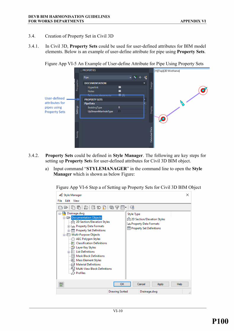
DEVB BIM HARMONISATION GUIDELINES FOR WORKS DEPARTMENTS APPENDIX VI
VI-10
3.4. Creation of Property Set in Civil 3D
3.4.1. In Civil 3D, Property Sets could be used for user-defined attributes for BIM model elements. Below is an example of user-define attribute for pipe using Property Sets.
Figure App VI-5 An Example of User-define Attribute for Pipe Using Property Sets
3.4.2. Property Sets could be defined in Style Manager. The following are key steps for setting up Property Sets for user-defined attributes for Civil 3D BIM object. a) Input command “STYLEMANAGER” in the command line to open the Style
Manager which is shown as below Figure:
Figure App VI-6 Step a of Setting up Property Sets for Civil 3D BIM Object
P100
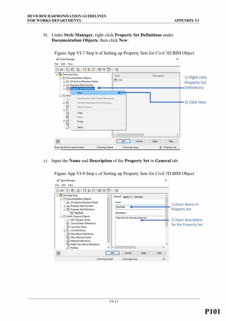
DEVB BIM HARMONISATION GUIDELINES FOR WORKS DEPARTMENTS APPENDIX VI
VI-11
b) Under Style Manager, right click Property Set Definitions under Documentation Objects, then click New.
Figure App VI-7 Step b of Setting up Property Sets for Civil 3D BIM Object
c) Input the Name and Description of the Property Set in General tab.
Figure App VI-8 Step c of Setting up Property Sets for Civil 3D BIM Object
P101
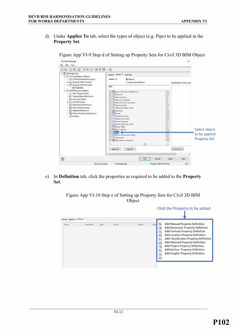
DEVB BIM HARMONISATION GUIDELINES FOR WORKS DEPARTMENTS APPENDIX VI
VI-12
d) Under Applies To tab, select the types of object (e.g. Pipe) to be applied in the Property Set.
Figure App VI-9 Step d of Setting up Property Sets for Civil 3D BIM Object
e) In Definition tab, click the properties as required to be added to the Property Set.
Figure App VI-10 Step e of Setting up Property Sets for Civil 3D BIM
Object
P102
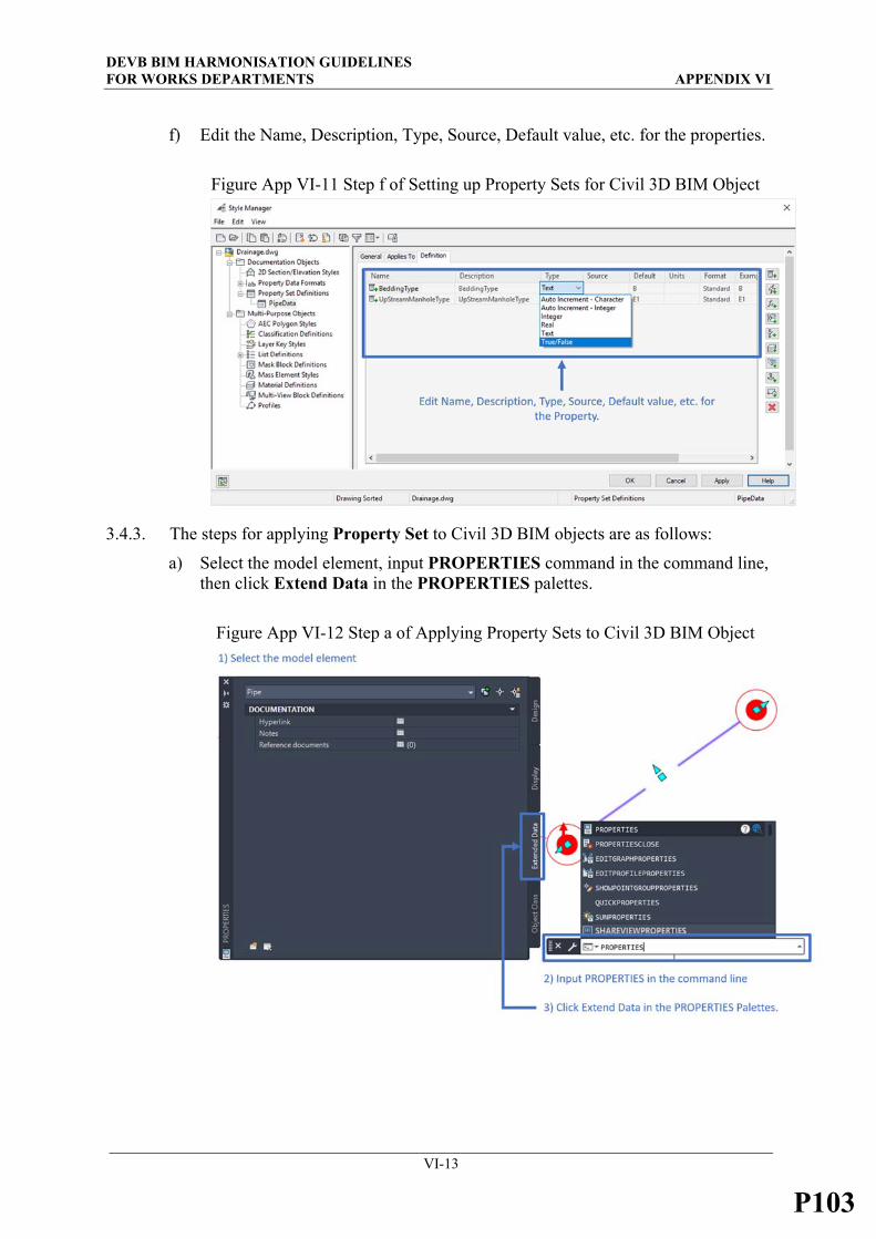
DEVB BIM HARMONISATION GUIDELINES FOR WORKS DEPARTMENTS APPENDIX VI
VI-13
f) Edit the Name, Description, Type, Source, Default value, etc. for the properties.
Figure App VI-11 Step f of Setting up Property Sets for Civil 3D BIM Object
3.4.3. The steps for applying Property Set to Civil 3D BIM objects are as follows: a) Select the model element, input PROPERTIES command in the command line,
then click Extend Data in the PROPERTIES palettes.
Figure App VI-12 Step a of Applying Property Sets to Civil 3D BIM Object
P103
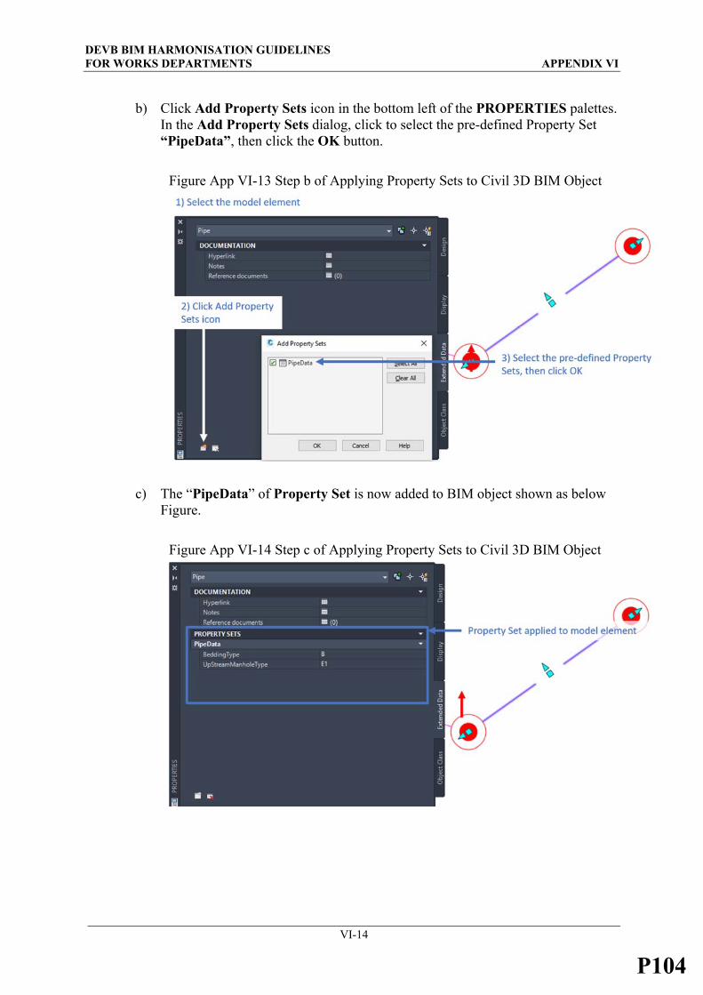
DEVB BIM HARMONISATION GUIDELINES FOR WORKS DEPARTMENTS APPENDIX VI
VI-14
b) Click Add Property Sets icon in the bottom left of the PROPERTIES palettes. In the Add Property Sets dialog, click to select the pre-defined Property Set “PipeData”, then click the OK button.
Figure App VI-13 Step b of Applying Property Sets to Civil 3D BIM Object
c) The “PipeData” of Property Set is now added to BIM object shown as below Figure.
Figure App VI-14 Step c of Applying Property Sets to Civil 3D BIM Object
P104
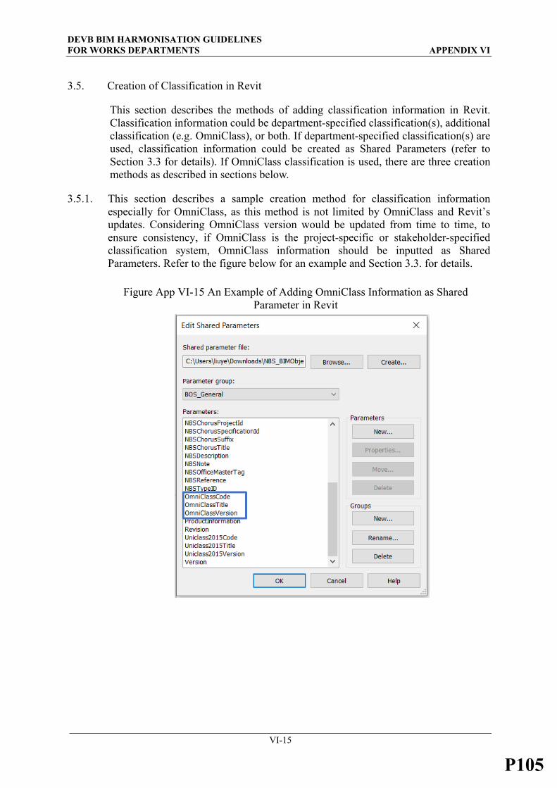
DEVB BIM HARMONISATION GUIDELINES FOR WORKS DEPARTMENTS APPENDIX VI
VI-15
3.5. Creation of Classification in Revit
This section describes the methods of adding classification information in Revit. Classification information could be department-specified classification(s), additional classification (e.g. OmniClass), or both. If department-specified classification(s) are used, classification information could be created as Shared Parameters (refer to Section 3.3 for details). If OmniClass classification is used, there are three creation methods as described in sections below.
3.5.1. This section describes a sample creation method for classification information especially for OmniClass, as this method is not limited by OmniClass and Revit’s updates. Considering OmniClass version would be updated from time to time, to ensure consistency, if OmniClass is the project-specific or stakeholder-specified classification system, OmniClass information should be inputted as Shared Parameters. Refer to the figure below for an example and Section 3.3. for details.
Figure App VI-15 An Example of Adding OmniClass Information as Shared
Parameter in Revit
P105
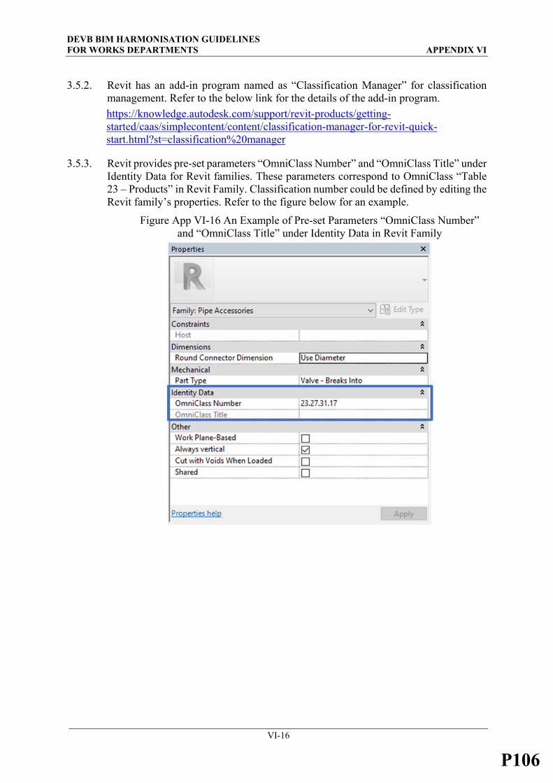
DEVB BIM HARMONISATION GUIDELINES FOR WORKS DEPARTMENTS APPENDIX VI
VI-16
3.5.2. Revit has an add-in program named as “Classification Manager” for classification management. Refer to the below link for the details of the add-in program. https://knowledge.autodesk.com/support/revit-products/getting-started/caas/simplecontent/content/classification-manager-for-revit-quick-start.html?st=classification%20manager
3.5.3. Revit provides pre-set parameters “OmniClass Number” and “OmniClass Title” under Identity Data for Revit families. These parameters correspond to OmniClass “Table 23 – Products” in Revit Family. Classification number could be defined by editing the Revit family’s properties. Refer to the figure below for an example.
Figure App VI-16 An Example of Pre-set Parameters “OmniClass Number” and “OmniClass Title” under Identity Data in Revit Family
P106
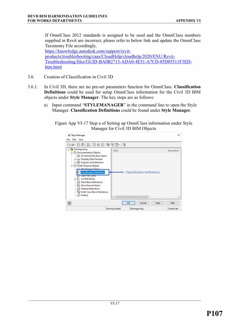
DEVB BIM HARMONISATION GUIDELINES FOR WORKS DEPARTMENTS APPENDIX VI
VI-17
If OmniClass 2012 standards is assigned to be used and the OmniClass numbers supplied in Revit are incorrect, please refer to below link and update the OmniClass Taxonomy File accordingly. https://knowledge.autodesk.com/support/revit-products/troubleshooting/caas/CloudHelp/cloudhelp/2020/ENU/Revit-Troubleshooting/files/GUID-BA0B2713-ADA0-4E51-A7CD-85D85511F3ED-htm.html
3.6. Creation of Classification in Civil 3D
3.6.1. In Civil 3D, there are no pre-set parameters function for OmniClass. Classification Definitions could be used for setup OmniClass information for the Civil 3D BIM objects under Style Manager. The key steps are as follows: a) Input command “STYLEMANAGER” in the command line to open the Style
Manager. Classification Definitions could be found under Style Manager.
Figure App VI-17 Step a of Setting up OmniClass information under Style Manager for Civil 3D BIM Objects
P107
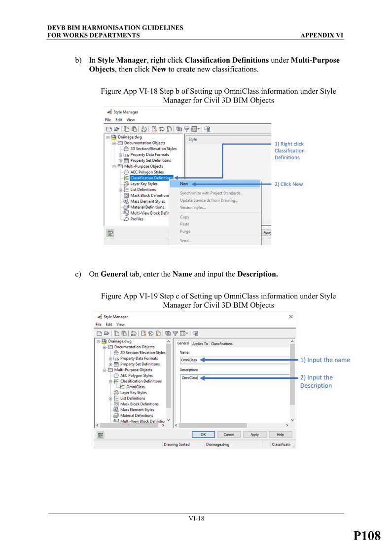
DEVB BIM HARMONISATION GUIDELINES FOR WORKS DEPARTMENTS APPENDIX VI
VI-18
b) In Style Manager, right click Classification Definitions under Multi-Purpose Objects, then click New to create new classifications.
Figure App VI-18 Step b of Setting up OmniClass information under Style
Manager for Civil 3D BIM Objects
c) On General tab, enter the Name and input the Description.
Figure App VI-19 Step c of Setting up OmniClass information under Style
Manager for Civil 3D BIM Objects
P108
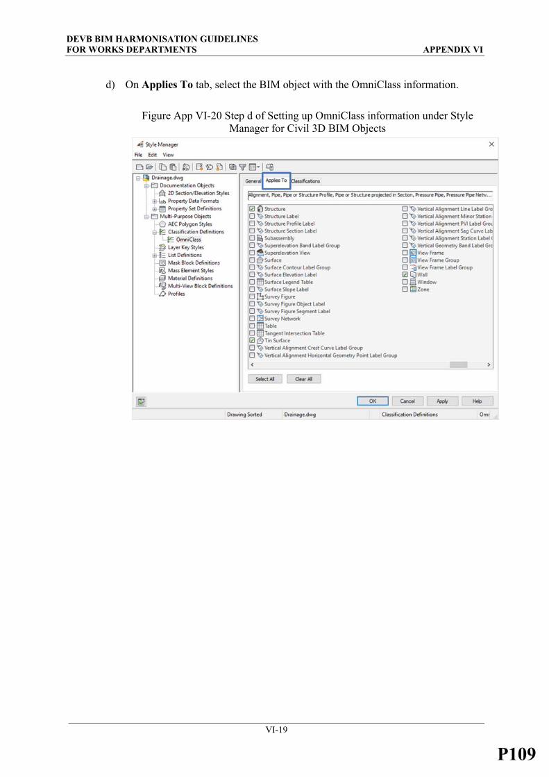
DEVB BIM HARMONISATION GUIDELINES FOR WORKS DEPARTMENTS APPENDIX VI
VI-19
d) On Applies To tab, select the BIM object with the OmniClass information.
Figure App VI-20 Step d of Setting up OmniClass information under Style Manager for Civil 3D BIM Objects
P109
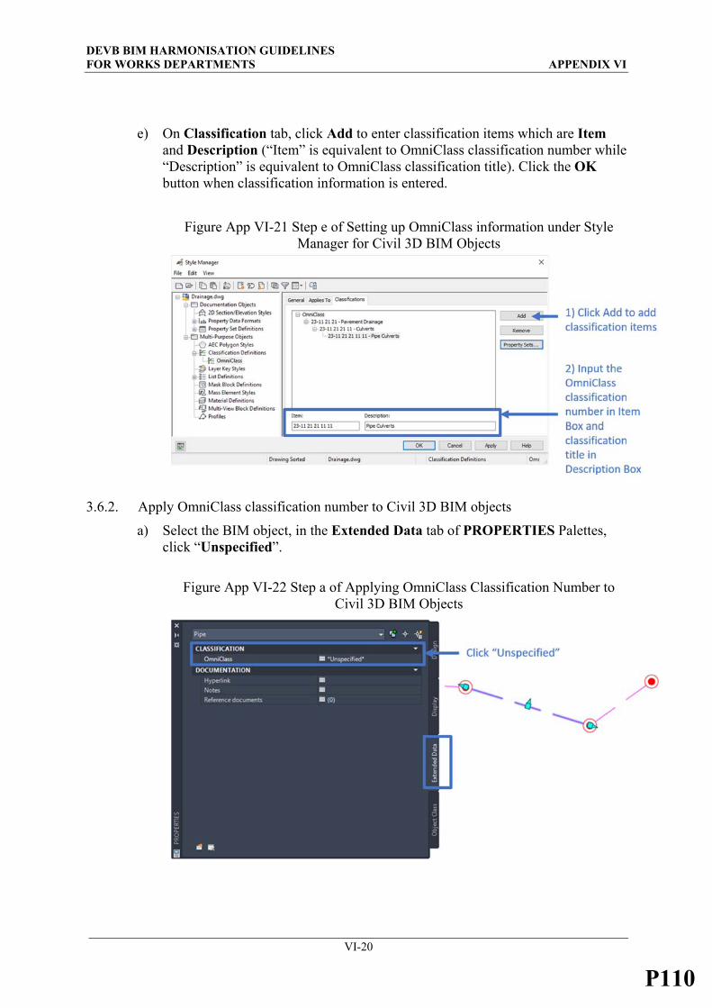
DEVB BIM HARMONISATION GUIDELINES FOR WORKS DEPARTMENTS APPENDIX VI
VI-20
e) On Classification tab, click Add to enter classification items which are Item
and Description (“Item” is equivalent to OmniClass classification number while “Description” is equivalent to OmniClass classification title). Click the OK button when classification information is entered.
Figure App VI-21 Step e of Setting up OmniClass information under Style
Manager for Civil 3D BIM Objects
3.6.2. Apply OmniClass classification number to Civil 3D BIM objects a) Select the BIM object, in the Extended Data tab of PROPERTIES Palettes,
click “Unspecified”.
Figure App VI-22 Step a of Applying OmniClass Classification Number to Civil 3D BIM Objects
P110
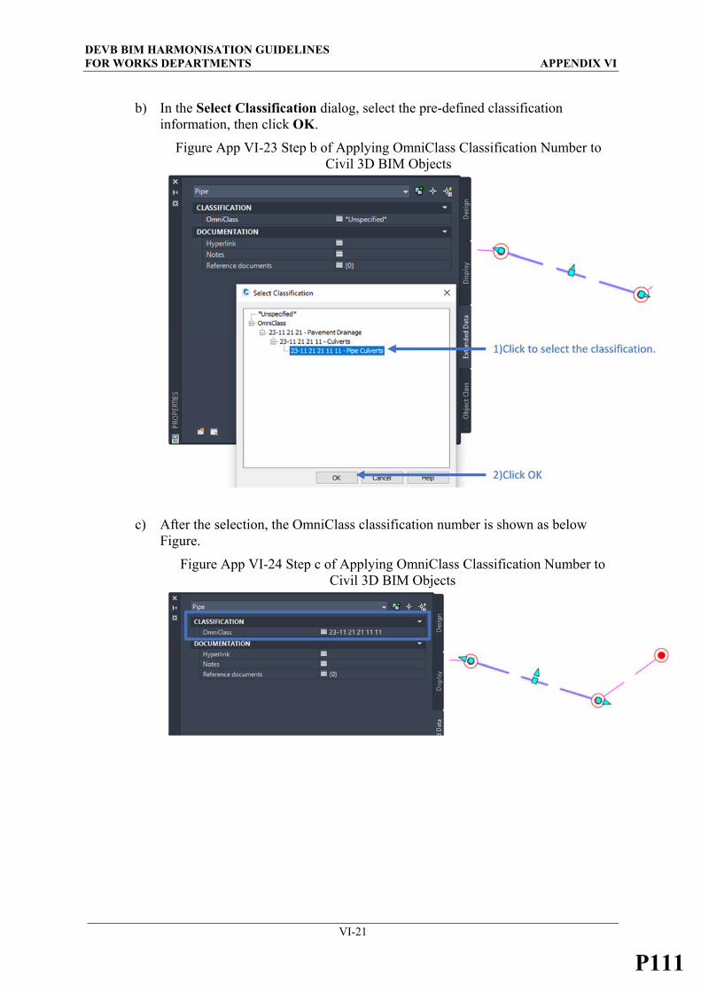
DEVB BIM HARMONISATION GUIDELINES FOR WORKS DEPARTMENTS APPENDIX VI
VI-21
b) In the Select Classification dialog, select the pre-defined classification information, then click OK.
Figure App VI-23 Step b of Applying OmniClass Classification Number to Civil 3D BIM Objects
c) After the selection, the OmniClass classification number is shown as below Figure.
Figure App VI-24 Step c of Applying OmniClass Classification Number to Civil 3D BIM Objects
P111
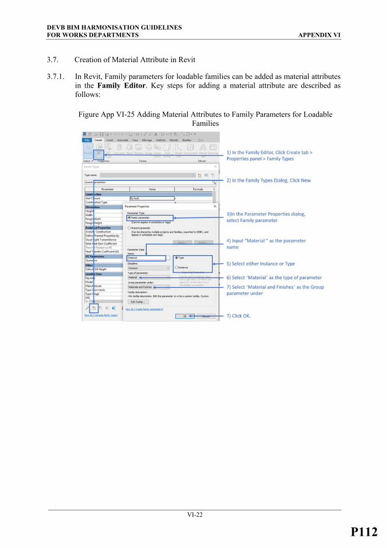
DEVB BIM HARMONISATION GUIDELINES FOR WORKS DEPARTMENTS APPENDIX VI
VI-22
3.7. Creation of Material Attribute in Revit
3.7.1. In Revit, Family parameters for loadable families can be added as material attributes in the Family Editor. Key steps for adding a material attribute are described as follows:
Figure App VI-25 Adding Material Attributes to Family Parameters for Loadable
Families
P112
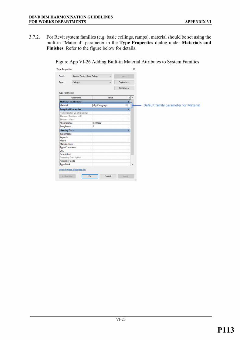
DEVB BIM HARMONISATION GUIDELINES FOR WORKS DEPARTMENTS APPENDIX VI
VI-23
3.7.2. For Revit system families (e.g. basic ceilings, ramps), material should be set using the built-in “Material” parameter in the Type Properties dialog under Materials and Finishes. Refer to the figure below for details.
Figure App VI-26 Adding Built-in Material Attributes to System Families
P113
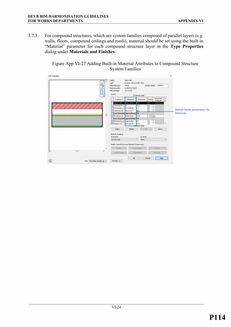
DEVB BIM HARMONISATION GUIDELINES FOR WORKS DEPARTMENTS APPENDIX VI
VI-24
3.7.3. For compound structures, which are system families composed of parallel layers (e.g. walls, floors, compound ceilings and roofs), material should be set using the built-in “Material” parameter for each compound structure layer in the Type Properties dialog under Materials and Finishes.
Figure App VI-27 Adding Built-in Material Attributes to Compound Structure
System Families
P114
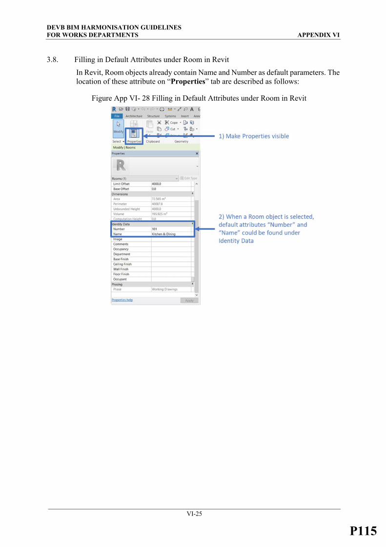
DEVB BIM HARMONISATION GUIDELINES FOR WORKS DEPARTMENTS APPENDIX VI
VI-25
3.8. Filling in Default Attributes under Room in Revit In Revit, Room objects already contain Name and Number as default parameters. The location of these attribute on “Properties” tab are described as follows:
Figure App VI- 28 Filling in Default Attributes under Room in Revit
P115
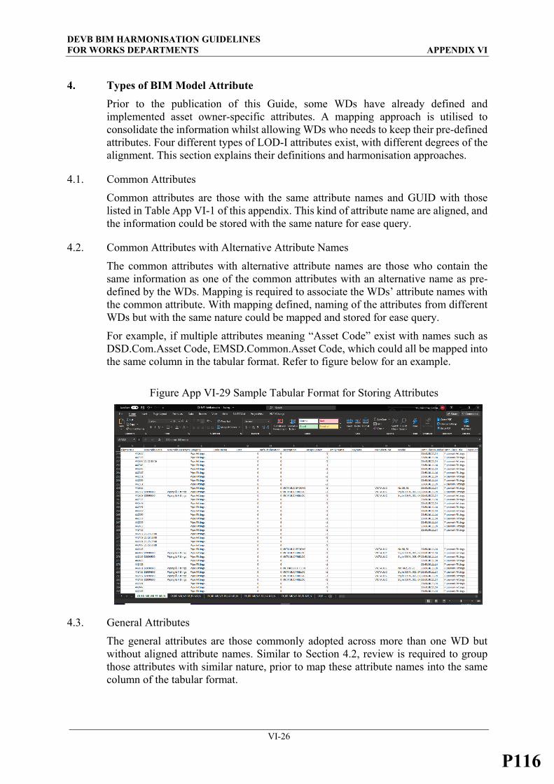
DEVB BIM HARMONISATION GUIDELINES FOR WORKS DEPARTMENTS APPENDIX VI
VI-26
4. Types of BIM Model Attribute
Prior to the publication of this Guide, some WDs have already defined and implemented asset owner-specific attributes. A mapping approach is utilised to consolidate the information whilst allowing WDs who needs to keep their pre-defined attributes. Four different types of LOD-I attributes exist, with different degrees of the alignment. This section explains their definitions and harmonisation approaches.
4.1. Common Attributes Common attributes are those with the same attribute names and GUID with those listed in Table App VI-1 of this appendix. This kind of attribute name are aligned, and the information could be stored with the same nature for ease query.
4.2. Common Attributes with Alternative Attribute Names The common attributes with alternative attribute names are those who contain the same information as one of the common attributes with an alternative name as pre-defined by the WDs. Mapping is required to associate the WDs’ attribute names with the common attribute. With mapping defined, naming of the attributes from different WDs but with the same nature could be mapped and stored for ease query. For example, if multiple attributes meaning “Asset Code” exist with names such as DSD.Com.Asset Code, EMSD.Common.Asset Code, which could all be mapped into the same column in the tabular format. Refer to figure below for an example.
Figure App VI-29 Sample Tabular Format for Storing Attributes
4.3. General Attributes The general attributes are those commonly adopted across more than one WD but without aligned attribute names. Similar to Section 4.2, review is required to group those attributes with similar nature, prior to map these attribute names into the same column of the tabular format.
P116
DEVB BIM HARMONISATION GUIDELINES FOR WORKS DEPARTMENTS APPENDIX VI
VI-27
4.4. Remaining Attributes Remaining attributes are the attributes that not classified as the common attributes and general attributes. Those attributes are discipline-oriented and not necessary to be aligned. Thus, the remaining attributes list could be stored without alterations to maintain the completeness of the information.
P117
DEVB BIM HARMONISATION GUIDELINES FOR WORKS DEPARTMENTS APPENDIX VI
VI-28
5. Mapping and Extraction of Attributes from BIM Models
5.1. Extraction Method Overview After attribute mapping, extraction of attributes from BIM models could be conducted through authoring software’s built-in functions, scripts or plug-ins. The sections below describe principles of attribute extraction from Revit and Civil 3D.
5.2. Extraction of Attributes from Revit The attributes in Revit can be exported to an external dataset in tabular format. The software default attributes and user defined attributes could be identified and extracted to tabular format. For example, Dynamo for Revit may be used to view and extract element parameters.
5.3. Extraction of Attributes from Civil 3D For Autodesk Civil 3D, since COBie spreadsheet cannot be exported directly from Civil 3D currently, Property Set should be defined in Civil 3D in order to extract the attributes in IFC format. Refer to Section 3.4 for details on Property Set.
P118

DEVB BIM HARMONISATION GUIDELINES FOR WORKS DEPARTMENTS APPENDIX VII
Appendix VII - Sample BIM Object Check Form
P119
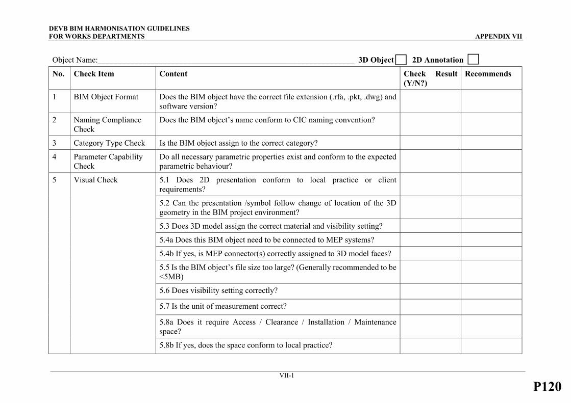
DEVB BIM HARMONISATION GUIDELINES FOR WORKS DEPARTMENTS APPENDIX VII
VII-1
Object Name:_______________________________________________________________ 3D Object 2D Annotation
No. Check Item Content Check Result (Y/N?)
Recommends
1 BIM Object Format Does the BIM object have the correct file extension (.rfa, .pkt, .dwg) and software version?
2 Naming Compliance Check
Does the BIM object’s name conform to CIC naming convention?
3 Category Type Check Is the BIM object assign to the correct category?
4 Parameter Capability Check
Do all necessary parametric properties exist and conform to the expected parametric behaviour?
5
Visual Check 5.1 Does 2D presentation conform to local practice or client requirements?
5.2 Can the presentation /symbol follow change of location of the 3D geometry in the BIM project environment?
5.3 Does 3D model assign the correct material and visibility setting?
5.4a Does this BIM object need to be connected to MEP systems?
5.4b If yes, is MEP connector(s) correctly assigned to 3D model faces?
5.5 Is the BIM object’s file size too large? (Generally recommended to be <5MB)
5.6 Does visibility setting correctly?
5.7 Is the unit of measurement correct?
5.8a Does it require Access / Clearance / Installation / Maintenance space?
5.8b If yes, does the space conform to local practice?
P120
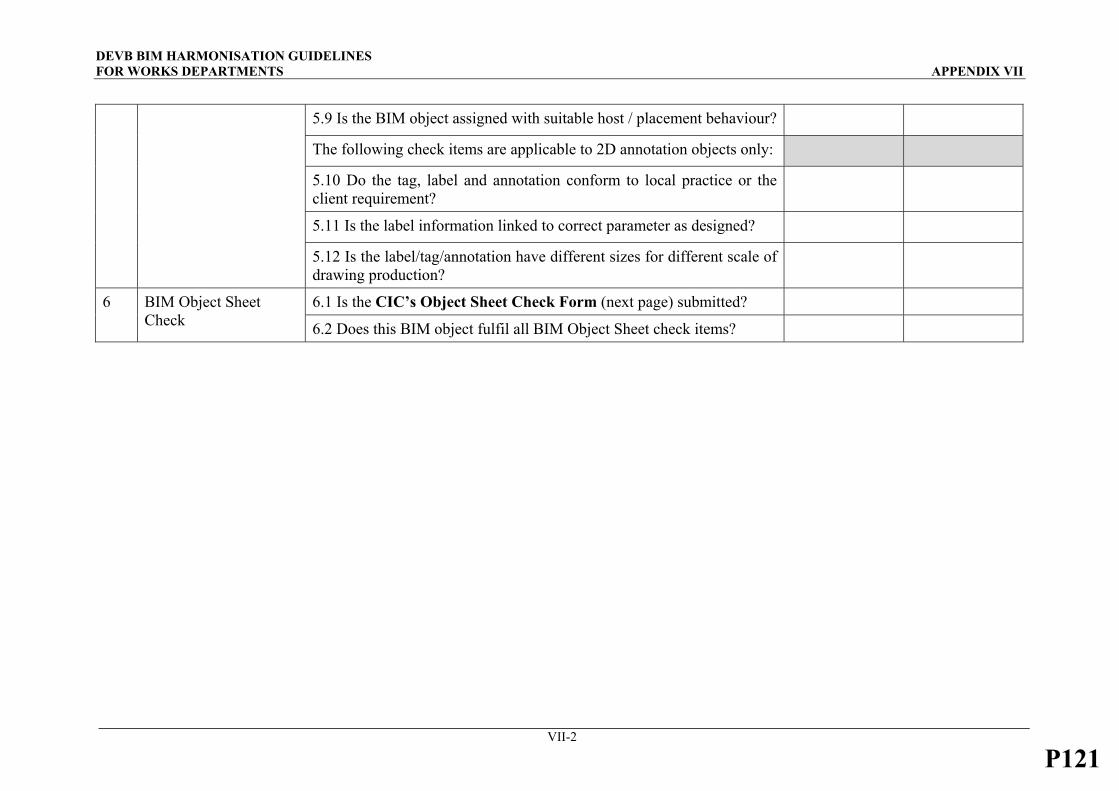
DEVB BIM HARMONISATION GUIDELINES FOR WORKS DEPARTMENTS APPENDIX VII
VII-2
5.9 Is the BIM object assigned with suitable host / placement behaviour?
The following check items are applicable to 2D annotation objects only:
5.10 Do the tag, label and annotation conform to local practice or the client requirement?
5.11 Is the label information linked to correct parameter as designed?
5.12 Is the label/tag/annotation have different sizes for different scale of drawing production?
6 BIM Object Sheet Check
6.1 Is the CIC’s Object Sheet Check Form (next page) submitted?
6.2 Does this BIM object fulfil all BIM Object Sheet check items?
P121
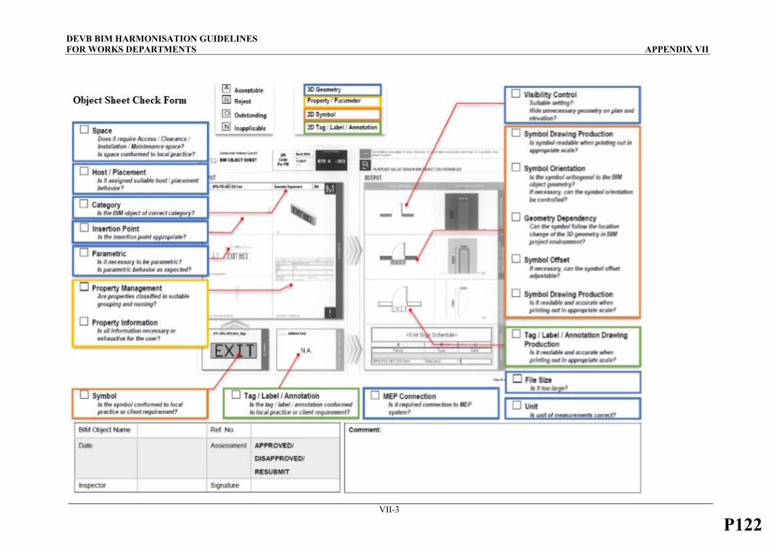
DEVB BIM HARMONISATION GUIDELINES FOR WORKS DEPARTMENTS APPENDIX VII
VII-3
P122
DEVB BIM HARMONISATION GUIDELINES FOR WORKS DEPARTMENTS APPENDIX VIII
– Federation Strategy Diagrams and Naming Examples
P123

DEVB BIM HARMONISATION GUIDELINES FOR WORKS DEPARTMENTS APPENDIX VIII
TABLE OF CONTENTS
1. Federation Strategy ........................................................................................................................ VIII-1 1.1. Federation Strategy for Field 3.2 (System): Building .................................................................... VIII-2 1.2. Federation Strategy for Field 3.2 (System): District Cooling System, Electrical Power Supply, Gas
Supply, Stormwater Drainage, Telecommunications ..................................................................... VIII-3 1.3. Federation Strategy for Field 3.2 (System): General Site Information, Geotechnical, Landscape . VIII-4 1.4. Federation Strategy for Field 3.2 (System): Sewerage ................................................................... VIII-5 1.5. Federation Strategy for Field 3.2 (System): Water Supply ............................................................ VIII-6 1.6. Federation Strategy for Field 3.2 (System): Road and Highway Structures ................................... VIII-7
2. Naming Examples for BIM Model ................................................................................................. VIII-8 2.1. Naming Example – a Subway Located in Volume C1 ................................................................... VIII-8 2.2. Naming Example – Sewage Pumping Station in Volume C2 ........................................................ VIII-9 2.3. Naming Example – a Market in Volume C6 ................................................................................ VIII-10
3. Naming Example for Drawings Generated from BIM Model ...................................................... VIII-11 3.1. Naming Example of Drawings ..................................................................................................... VIII-11
List of Figures
Figure App VIII-1 Federation Strategy for Field 3.2 (System): Building ...................................................... VIII-2
Figure App VIII-2 Federation Strategy for Field 3.2 (System): District Cooling System, Electrical Power Supply, Gas Supply, Stormwater Drainage, Telecommunications ................................................................. VIII-3
Figure App VIII-3 Federation Strategy for Field 3.2 (System): General Site Information, Geotechnical, Landscape ....................................................................................................................................................... VIII-4
Figure App VIII-4 Federation Strategy for Field 3.2 (System): Sewerage ..................................................... VIII-5
Figure App VIII-5 Federation Strategy for Field 3.2 (System): Water Supply .............................................. VIII-6
Figure App VIII-6 Federation Strategy for Field 3.2 (System): Road and Highway Structures ..................... VIII-7
Figure App VIII-7 Naming Example for a Subway ........................................................................................ VIII-8
Figure App VIII-8 Naming Example for Combined Model ........................................................................... VIII-8
Figure App VIII-9 Naming Example for Sewage Pumping Station ............................................................... VIII-9
Figure App VIII-10 Naming Example for Different Project .......................................................................... VIII-9
Figure App VIII-11 Naming Example for a Market Building ...................................................................... VIII-10
Figure App VIII-12 Naming Example for the Market Building with MEP BIM Models ............................ VIII-10
Figure App VIII-13 Naming Example of Drawings Generated from BIM Model ....................................... VIII-11
P124
DEVB BIM HARMONISATION GUIDELINES FOR WORKS DEPARTMENTS APPENDIX VIII
VIII-1
1. Federation Strategy
Figure App VIII-1 to Figure App VIII-6 are examples demonstrating the federation strategies for different systems within a project. As some items may not be included in the figures, refer to Appendix X for the list of common codes. In Figure App VIII-1 below, it is not mandatory for Architectural, Structural and Stormwater Drainage disciplines to be further subdivided into subdiscipline model files. Also, in Figure App VIII-6, pavement, road drainage, road lighting, road furniture and noise barrier are known subdisciplines, while walkway cover, subway cover and concrete structural frame of lift tower should belong to other disciplines such as Architectural and Structural to facilitate information container breakdown.
P125
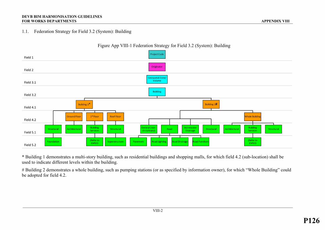
DEVB BIM HARMONISATION GUIDELINES FOR WORKS DEPARTMENTS APPENDIX VIII
VIII-2
1.1. Federation Strategy for Field 3.2 (System): Building
Figure App VIII-1 Federation Strategy for Field 3.2 (System): Building
* Building 1 demonstrates a multi-story building, such as residential buildings and shopping malls, for which field 4.2 (sub-location) shall be used to indicate different levels within the building. # Building 2 demonstrates a whole building, such as pumping stations (or as specified by information owner), for which “Whole Building” could be adopted for field 4.2.
P126
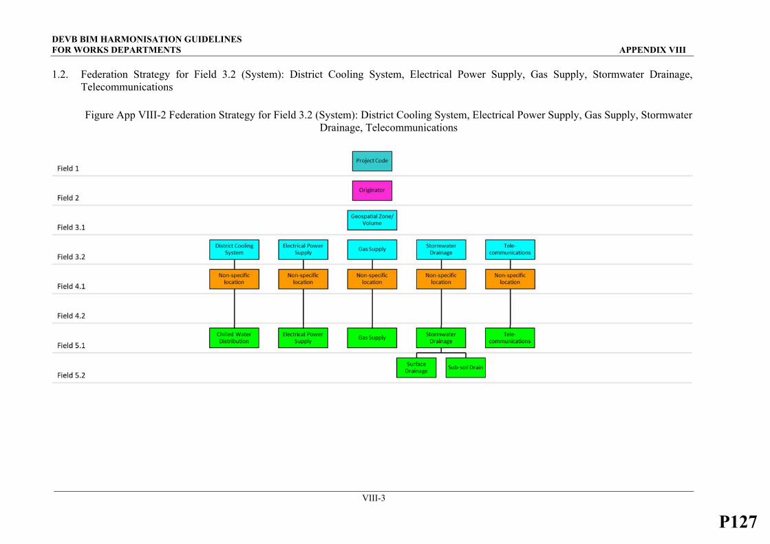
DEVB BIM HARMONISATION GUIDELINES FOR WORKS DEPARTMENTS APPENDIX VIII
VIII-3
1.2. Federation Strategy for Field 3.2 (System): District Cooling System, Electrical Power Supply, Gas Supply, Stormwater Drainage, Telecommunications Figure App VIII-2 Federation Strategy for Field 3.2 (System): District Cooling System, Electrical Power Supply, Gas Supply, Stormwater
Drainage, Telecommunications
P127
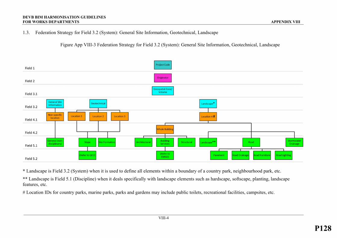
DEVB BIM HARMONISATION GUIDELINES FOR WORKS DEPARTMENTS APPENDIX VIII
VIII-4
1.3. Federation Strategy for Field 3.2 (System): General Site Information, Geotechnical, Landscape
Figure App VIII-3 Federation Strategy for Field 3.2 (System): General Site Information, Geotechnical, Landscape
* Landscape is Field 3.2 (System) when it is used to define all elements within a boundary of a country park, neighbourhood park, etc. ** Landscape is Field 5.1 (Discipline) when it deals specifically with landscape elements such as hardscape, softscape, planting, landscape features, etc. # Location IDs for country parks, marine parks, parks and gardens may include public toilets, recreational facilities, campsites, etc.
P128
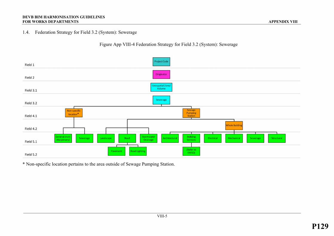
DEVB BIM HARMONISATION GUIDELINES FOR WORKS DEPARTMENTS APPENDIX VIII
VIII-5
1.4. Federation Strategy for Field 3.2 (System): Sewerage
Figure App VIII-4 Federation Strategy for Field 3.2 (System): Sewerage
* Non-specific location pertains to the area outside of Sewage Pumping Station.
P129
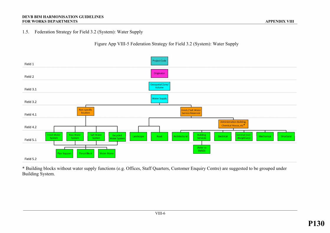
DEVB BIM HARMONISATION GUIDELINES FOR WORKS DEPARTMENTS APPENDIX VIII
VIII-6
1.5. Federation Strategy for Field 3.2 (System): Water Supply
Figure App VIII-5 Federation Strategy for Field 3.2 (System): Water Supply
* Building blocks without water supply functions (e.g. Offices, Staff Quarters, Customer Enquiry Centre) are suggested to be grouped under Building System.
P130
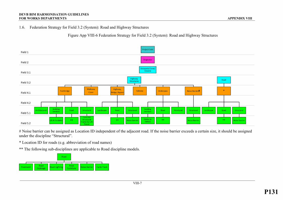
DEVB BIM HARMONISATION GUIDELINES FOR WORKS DEPARTMENTS APPENDIX VIII
VIII-7
1.6. Federation Strategy for Field 3.2 (System): Road and Highway Structures
Figure App VIII-6 Federation Strategy for Field 3.2 (System): Road and Highway Structures
# Noise barrier can be assigned as Location ID independent of the adjacent road. If the noise barrier exceeds a certain size, it should be assigned under the discipline “Structural”. * Location ID for roads (e.g. abbreviation of road names) ** The following sub-disciplines are applicable to Road discipline models.
P131
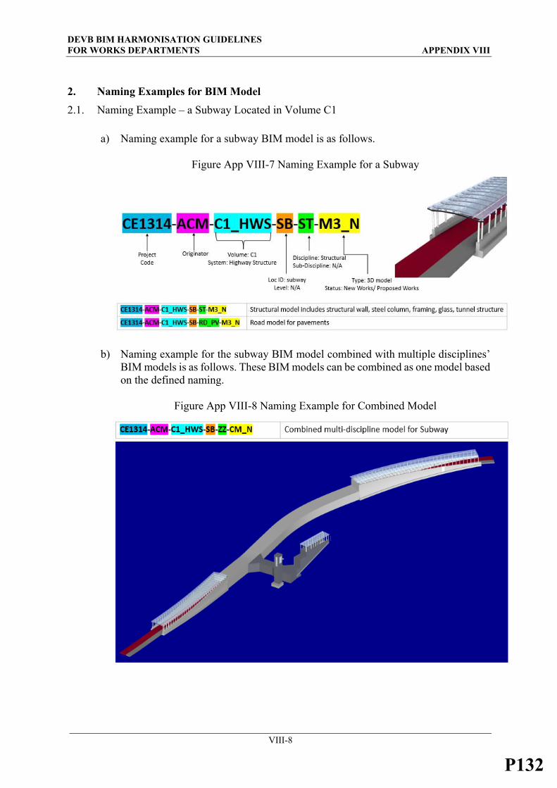
DEVB BIM HARMONISATION GUIDELINES FOR WORKS DEPARTMENTS APPENDIX VIII
VIII-8
2. Naming Examples for BIM Model
2.1. Naming Example – a Subway Located in Volume C1 a) Naming example for a subway BIM model is as follows.
Figure App VIII-7 Naming Example for a Subway
b) Naming example for the subway BIM model combined with multiple disciplines’ BIM models is as follows. These BIM models can be combined as one model based on the defined naming.
Figure App VIII-8 Naming Example for Combined Model
P132
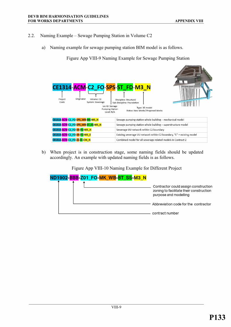
DEVB BIM HARMONISATION GUIDELINES FOR WORKS DEPARTMENTS APPENDIX VIII
VIII-9
2.2. Naming Example – Sewage Pumping Station in Volume C2 a) Naming example for sewage pumping station BIM model is as follows.
Figure App VIII-9 Naming Example for Sewage Pumping Station
b) When project is in construction stage, some naming fields should be updated accordingly. An example with updated naming fields is as follows.
Figure App VIII-10 Naming Example for Different Project
P133
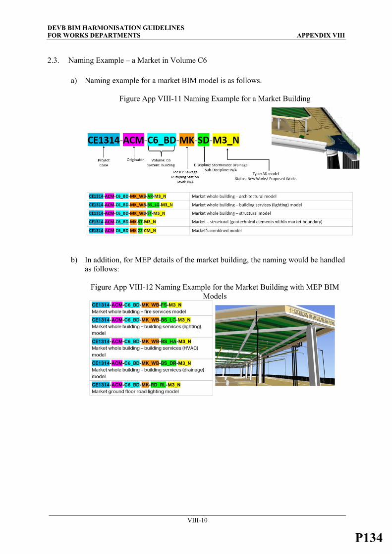
DEVB BIM HARMONISATION GUIDELINES FOR WORKS DEPARTMENTS APPENDIX VIII
VIII-10
2.3. Naming Example – a Market in Volume C6 a) Naming example for a market BIM model is as follows.
Figure App VIII-11 Naming Example for a Market Building
b) In addition, for MEP details of the market building, the naming would be handled
as follows:
Figure App VIII-12 Naming Example for the Market Building with MEP BIM Models
P134
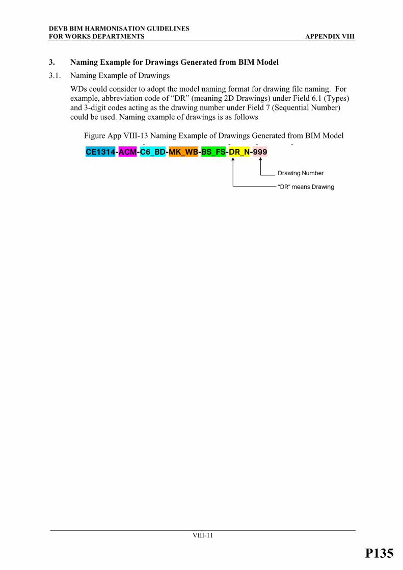
DEVB BIM HARMONISATION GUIDELINES FOR WORKS DEPARTMENTS APPENDIX VIII
VIII-11
3. Naming Example for Drawings Generated from BIM Model
3.1. Naming Example of Drawings WDs could consider to adopt the model naming format for drawing file naming. For example, abbreviation code of “DR” (meaning 2D Drawings) under Field 6.1 (Types) and 3-digit codes acting as the drawing number under Field 7 (Sequential Number) could be used. Naming example of drawings is as follows
Figure App VIII-13 Naming Example of Drawings Generated from BIM Model
P135

DEVB BIM HARMONISATION GUIDELINES FOR WORKS DEPARTMENTS APPENDIX IX
– Sample Project-specific Codes for Naming
P136
DEVB BIM HARMONISATION GUIDELINES FOR WORKS DEPARTMENTS APPENDIX IX
TABLE OF CONTENTS
1. Introduction ....................................................................................................................................... IX-1
2. Codes for Field 1 – Project ................................................................................................................ IX-1
3. Codes for Field 3.1 – Volume ........................................................................................................... IX-2
4. Codes for Field 4.1 – Location .......................................................................................................... IX-8
List of Tables
Table App IX-1 Codes for Field 1 – Project ...................................................................................................... IX-1
Table App IX-2 Codes for Field 3.1 – Volume ................................................................................................. IX-2
Table App IX-3 Codes for Field 4.1 – Location Identifier ................................................................................ IX-8
P137
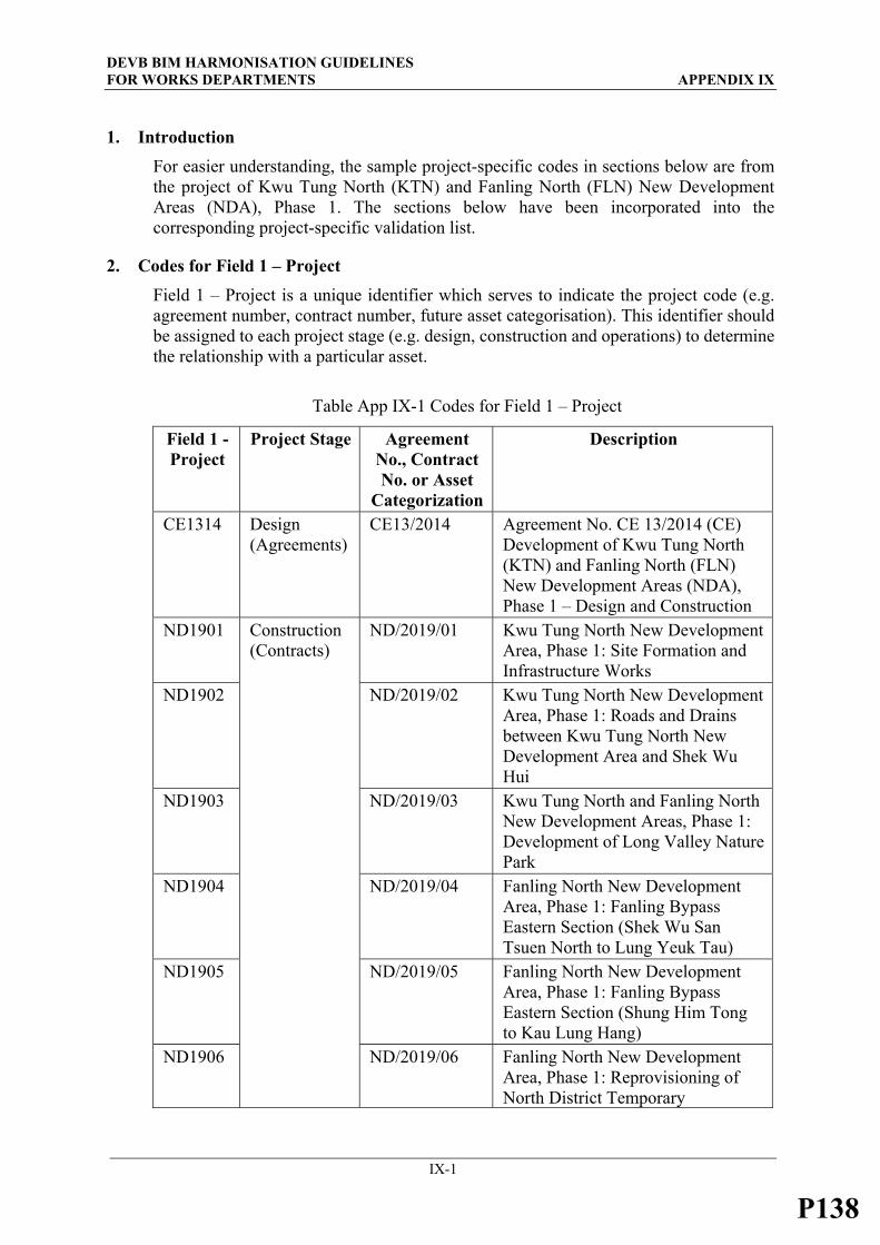
DEVB BIM HARMONISATION GUIDELINES FOR WORKS DEPARTMENTS APPENDIX IX
IX-1
1. Introduction
For easier understanding, the sample project-specific codes in sections below are from the project of Kwu Tung North (KTN) and Fanling North (FLN) New Development Areas (NDA), Phase 1. The sections below have been incorporated into the corresponding project-specific validation list.
2. Codes for Field 1 – Project
Field 1 – Project is a unique identifier which serves to indicate the project code (e.g. agreement number, contract number, future asset categorisation). This identifier should be assigned to each project stage (e.g. design, construction and operations) to determine the relationship with a particular asset.
Table App IX-1 Codes for Field 1 – Project
Field 1 - Project
Project Stage Agreement No., Contract No. or Asset
Categorization
Description
CE1314 Design (Agreements)
CE13/2014 Agreement No. CE 13/2014 (CE) Development of Kwu Tung North (KTN) and Fanling North (FLN) New Development Areas (NDA), Phase 1 – Design and Construction
ND1901 Construction (Contracts)
ND/2019/01 Kwu Tung North New Development Area, Phase 1: Site Formation and Infrastructure Works
ND1902 ND/2019/02 Kwu Tung North New Development Area, Phase 1: Roads and Drains between Kwu Tung North New Development Area and Shek Wu Hui
ND1903 ND/2019/03 Kwu Tung North and Fanling North New Development Areas, Phase 1: Development of Long Valley Nature Park
ND1904 ND/2019/04 Fanling North New Development Area, Phase 1: Fanling Bypass Eastern Section (Shek Wu San Tsuen North to Lung Yeuk Tau)
ND1905 ND/2019/05 Fanling North New Development Area, Phase 1: Fanling Bypass Eastern Section (Shung Him Tong to Kau Lung Hang)
ND1906 ND/2019/06 Fanling North New Development Area, Phase 1: Reprovisioning of North District Temporary
P138
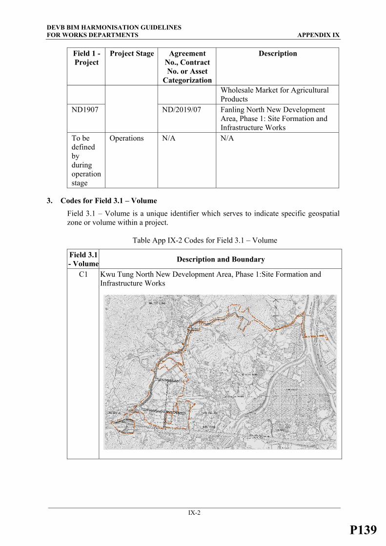
DEVB BIM HARMONISATION GUIDELINES FOR WORKS DEPARTMENTS APPENDIX IX
IX-2
Field 1 - Project
Project Stage Agreement No., Contract No. or Asset
Categorization
Description
Wholesale Market for Agricultural Products
ND1907 ND/2019/07 Fanling North New Development Area, Phase 1: Site Formation and Infrastructure Works
To be defined by during operation stage
Operations N/A N/A
3. Codes for Field 3.1 – Volume
Field 3.1 – Volume is a unique identifier which serves to indicate specific geospatial zone or volume within a project.
Table App IX-2 Codes for Field 3.1 – Volume
Field 3.1 - Volume
Description and Boundary
C1 Kwu Tung North New Development Area, Phase 1:Site Formation and Infrastructure Works
P139
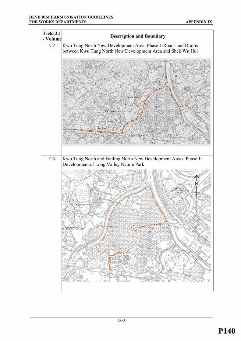
DEVB BIM HARMONISATION GUIDELINES FOR WORKS DEPARTMENTS APPENDIX IX
IX-3
Field 3.1 - Volume
Description and Boundary
C2 Kwu Tung North New Development Area, Phase 1:Roads and Drains between Kwu Tung North New Development Area and Shek Wu Hui
C3 Kwu Tung North and Fanling North New Development Areas, Phase 1:
Development of Long Valley Nature Park
P140
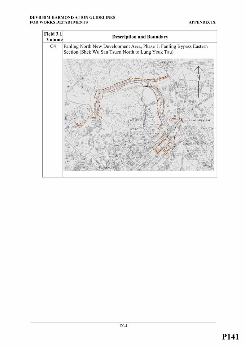
DEVB BIM HARMONISATION GUIDELINES FOR WORKS DEPARTMENTS APPENDIX IX
IX-4
Field 3.1 - Volume
Description and Boundary
C4 Fanling North New Development Area, Phase 1: Fanling Bypass Eastern Section (Shek Wu San Tsuen North to Lung Yeuk Tau)
P141
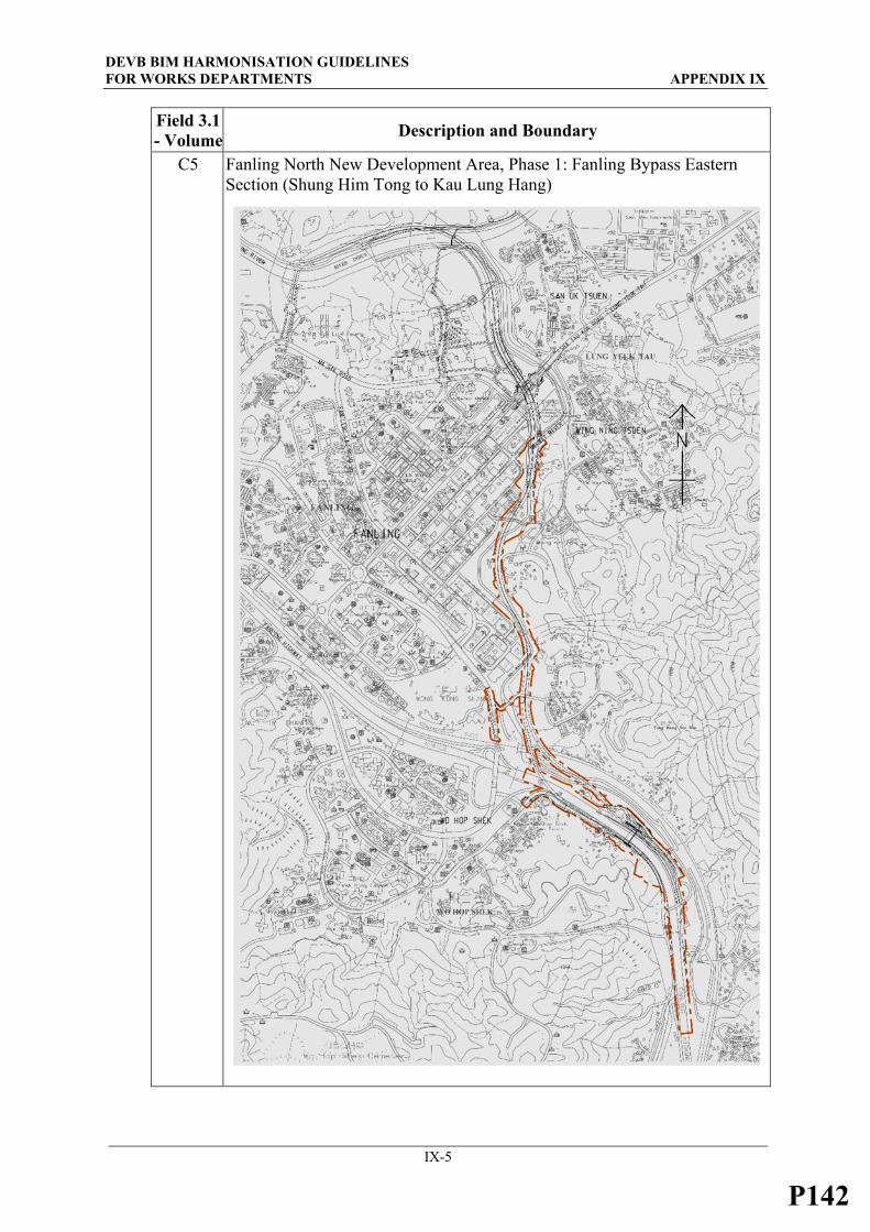
DEVB BIM HARMONISATION GUIDELINES FOR WORKS DEPARTMENTS APPENDIX IX
IX-5
Field 3.1 - Volume
Description and Boundary
C5 Fanling North New Development Area, Phase 1: Fanling Bypass Eastern Section (Shung Him Tong to Kau Lung Hang)
P142
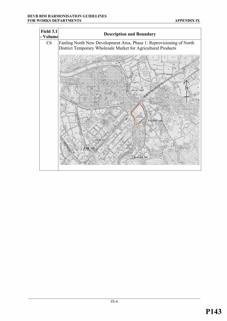
DEVB BIM HARMONISATION GUIDELINES FOR WORKS DEPARTMENTS APPENDIX IX
IX-6
Field 3.1 - Volume
Description and Boundary
C6 Fanling North New Development Area, Phase 1: Reprovisioning of North District Temporary Wholesale Market for Agricultural Products
P143
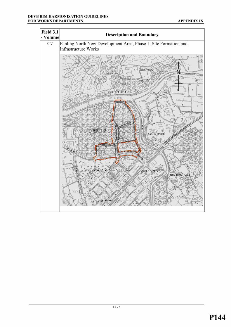
DEVB BIM HARMONISATION GUIDELINES FOR WORKS DEPARTMENTS APPENDIX IX
IX-7
Field 3.1 - Volume
Description and Boundary
C7 Fanling North New Development Area, Phase 1: Site Formation and Infrastructure Works
P144
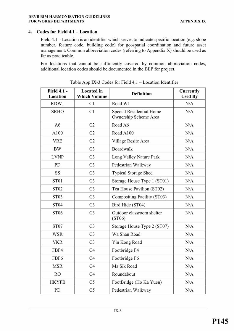
DEVB BIM HARMONISATION GUIDELINES FOR WORKS DEPARTMENTS APPENDIX IX
IX-8
4. Codes for Field 4.1 – Location
Field 4.1 – Location is an identifier which serves to indicate specific location (e.g. slope number, feature code, building code) for geospatial coordination and future asset management. Common abbreviation codes (referring to Appendix X) should be used as far as practicable. For locations that cannot be sufficiently covered by common abbreviation codes, additional location codes should be documented in the BEP for project.
Table App IX-3 Codes for Field 4.1 – Location Identifier
Field 4.1 - Location
Located in Which Volume
Definition Currently Used By
RDW1 C1 Road W1 N/A
SRHO C1 Special Residential Home Ownership Scheme Area
N/A
A6 C2 Road A6 N/A
A100 C2 Road A100 N/A
VRE C2 Village Resite Area N/A
BW C3 Boardwalk N/A
LVNP C3 Long Valley Nature Park N/A
PD C3 Pedestrian Walkway N/A
SS C3 Typical Storage Shed N/A
ST01 C3 Storage House Type 1 (ST01) N/A
ST02 C3 Tea House Pavilion (ST02) N/A
ST03 C3 Compositing Facility (ST03) N/A
ST04 C3 Bird Hide (ST04) N/A
ST06 C3 Outdoor classroom shelter (ST06)
N/A
ST07 C3 Storage House Type 2 (ST07) N/A
WSR C3 Wa Shan Road N/A
YKR C3 Yin Kong Road N/A
FBF4 C4 Footbridge F4 N/A
FBF6 C4 Footbridge F6 N/A
MSR C4 Ma Sik Road N/A
RO C4 Roundabout N/A
HKYFB C5 FootBridge (Ho Ka Yuen) N/A
PD C5 Pedestrian Walkway N/A
P145
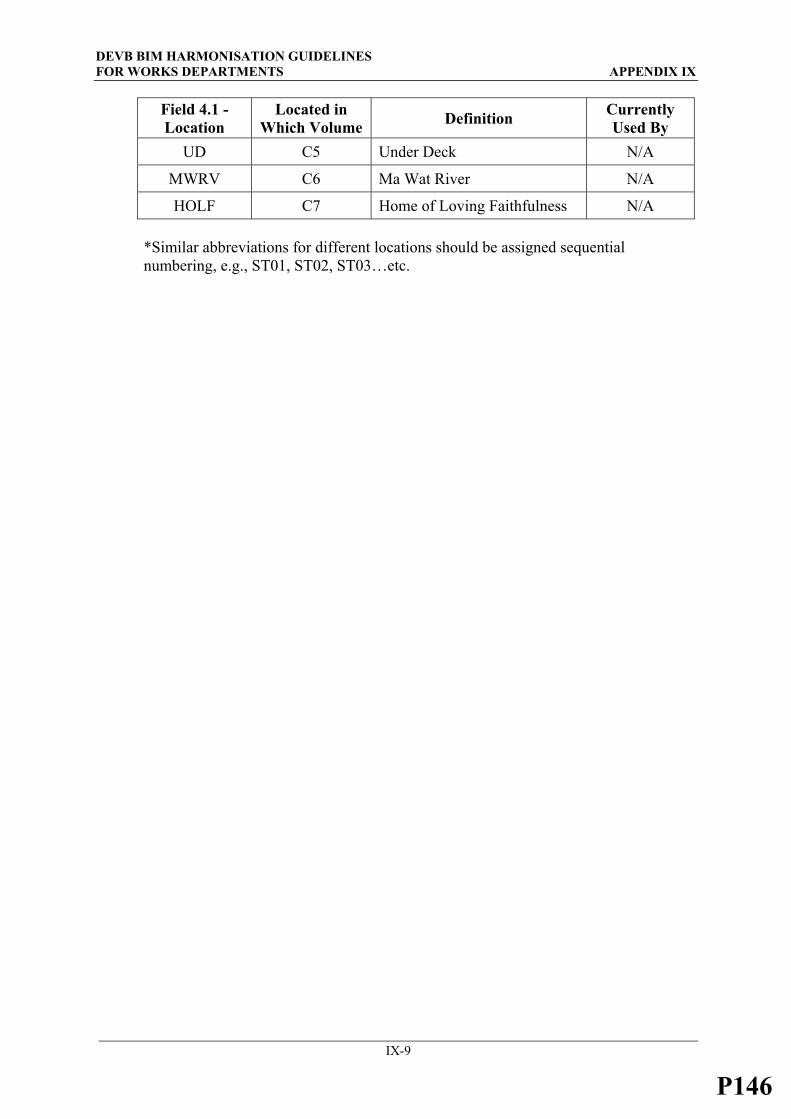
DEVB BIM HARMONISATION GUIDELINES FOR WORKS DEPARTMENTS APPENDIX IX
IX-9
Field 4.1 - Location
Located in Which Volume
Definition Currently Used By
UD C5 Under Deck N/A
MWRV C6 Ma Wat River N/A
HOLF C7 Home of Loving Faithfulness N/A
*Similar abbreviations for different locations should be assigned sequential numbering, e.g., ST01, ST02, ST03…etc.
P146

DEVB BIM HARMONISATION GUIDELINES FOR WORKS DEPARTMENTS APPENDIX X
– Common Codes for Information Container ID Fields
P147
DEVB BIM HARMONISATION GUIDELINES FOR WORKS DEPARTMENTS APPENDIX X
List of Tables
Table App X-1 Abbreviation Codes for Field 3.2 – System ............................................................................... X-1
Table App X-2 Abbreviation Codes for Field 4.1 – Location ............................................................................ X-2
Table App X-3 Abbreviation Codes for Field 4.2 – Sub-location ...................................................................... X-6
Table App X-4 Abbreviation Codes for Field 4.2 – Sub-location (Levels) ........................................................ X-8
Table App X-5 Abbreviation Codes for Field 5.1 – Discipline .......................................................................... X-9
Table App X-6 Abbreviation Codes for Field 5.2 – Sub-discipline ................................................................. X-10
Table App X-7 Abbreviation Codes for Field 6.1 – Type ................................................................................ X-13
Table App X-8 Abbreviation Codes for Field 6.2 – Characteristic .................................................................. X-15
P148
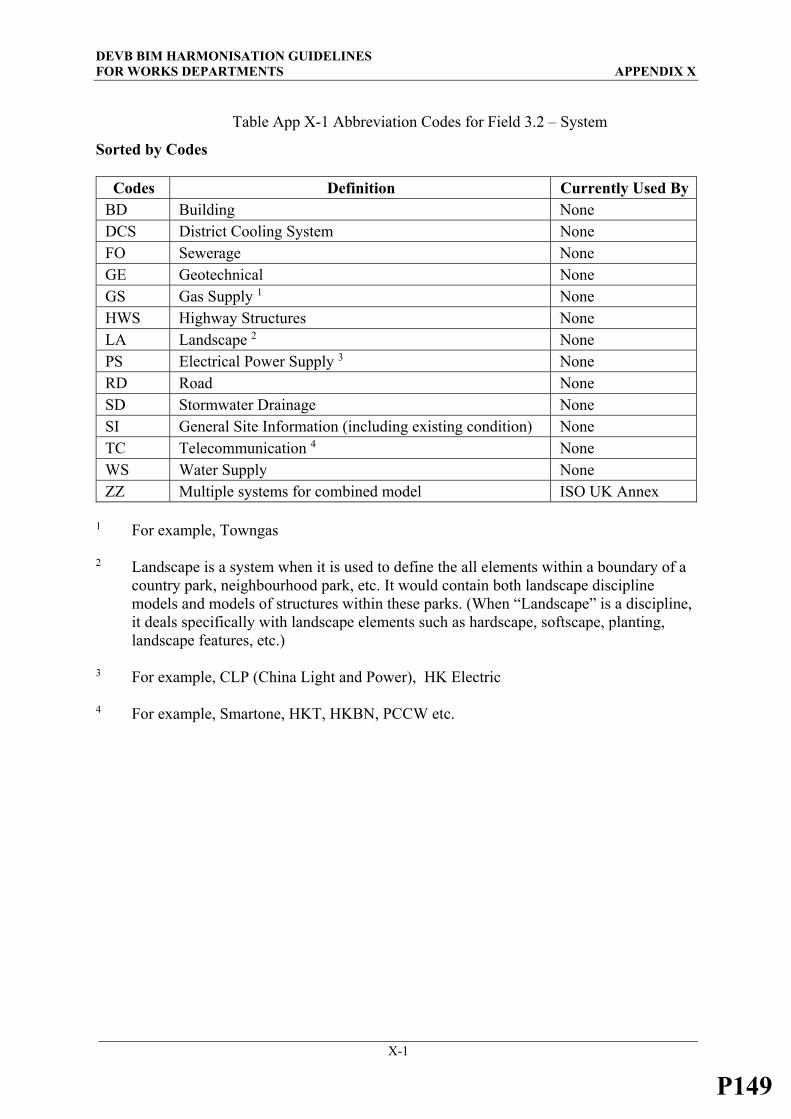
DEVB BIM HARMONISATION GUIDELINES FOR WORKS DEPARTMENTS APPENDIX X
X-1
Table App X-1 Abbreviation Codes for Field 3.2 – System
Sorted by Codes
Codes Definition Currently Used By BD Building None DCS District Cooling System None FO Sewerage None GE Geotechnical None GS Gas Supply 1 None HWS Highway Structures None LA Landscape 2 None PS Electrical Power Supply 3 None RD Road None SD Stormwater Drainage None SI General Site Information (including existing condition) None TC Telecommunication 4 None WS Water Supply None ZZ Multiple systems for combined model ISO UK Annex
1 For example, Towngas 2 Landscape is a system when it is used to define the all elements within a boundary of a
country park, neighbourhood park, etc. It would contain both landscape discipline models and models of structures within these parks. (When “Landscape” is a discipline, it deals specifically with landscape elements such as hardscape, softscape, planting, landscape features, etc.)
3 For example, CLP (China Light and Power), HK Electric 4 For example, Smartone, HKT, HKBN, PCCW etc.
P149
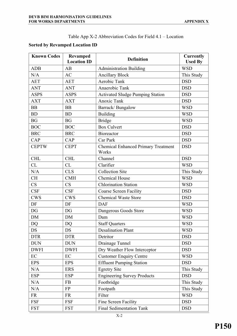
DEVB BIM HARMONISATION GUIDELINES FOR WORKS DEPARTMENTS APPENDIX X
X-2
Table App X-2 Abbreviation Codes for Field 4.1 – Location
Sorted by Revamped Location ID
Known Codes Revamped Location ID Definition Currently
Used By ADB AB Administration Building WSD N/A AC Ancillary Block This Study AET AET Aerobic Tank DSD ANT ANT Anaerobic Tank DSD ASPS ASPS Activated Sludge Pumping Station DSD AXT AXT Anoxic Tank DSD BB BB Barrack/ Bungalow WSD BD BD Building WSD BG BG Bridge WSD BOC BOC Box Culvert DSD BRC BRC Bioreactor DSD CAP CAP Car Park DSD CEPTW CEPT Chemical Enhanced Primary Treatment
Works DSD
CHL CHL Channel DSD CL CL Clarifier WSD N/A CLS Collection Site This Study CH CMH Chemical House WSD CS CS Chlorination Station WSD CSF CSF Coarse Screen Facility DSD CWS CWS Chemical Waste Store DSD DF DF DAF WSD DG DG Dangerous Goods Store WSD DM DM Dam WSD DQ DQ Staff Quarters WSD DS DS Desalination Plant WSD DTR DTR Detritor DSD DUN DUN Drainage Tunnel DSD DWFI DWFI Dry Weather Flow Interceptor DSD EC EC Customer Enquiry Centre WSD EPS EPS Effluent Pumping Station DSD N/A ERS Egretry Site This Study ESP ESP Engineering Survey Products DSD N/A FB Footbridge This Study N/A FP Footpath This Study FR FR Filter WSD FSF FSF Fine Screen Facility DSD FST FST Final Sedimentation Tank DSD
P150
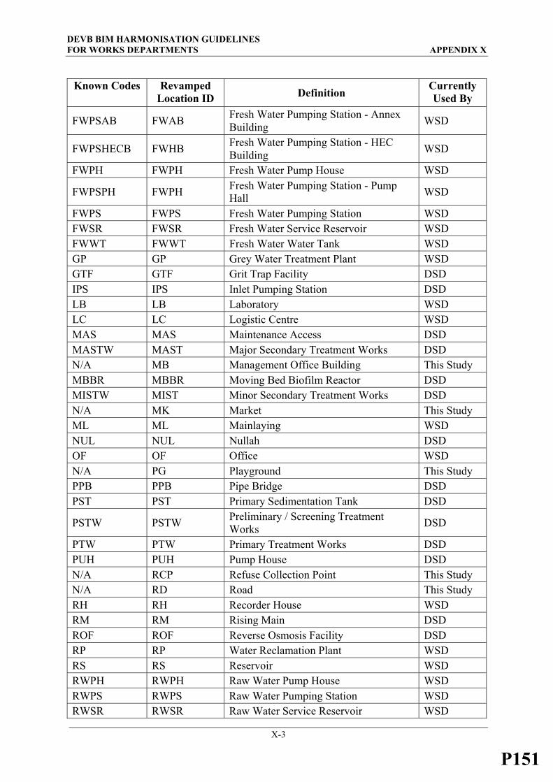
DEVB BIM HARMONISATION GUIDELINES FOR WORKS DEPARTMENTS APPENDIX X
X-3
Known Codes Revamped Location ID Definition Currently
Used By
FWPSAB FWAB Fresh Water Pumping Station - Annex Building WSD
FWPSHECB FWHB Fresh Water Pumping Station - HEC Building WSD
FWPH FWPH Fresh Water Pump House WSD
FWPSPH FWPH Fresh Water Pumping Station - Pump Hall WSD
FWPS FWPS Fresh Water Pumping Station WSD FWSR FWSR Fresh Water Service Reservoir WSD FWWT FWWT Fresh Water Water Tank WSD GP GP Grey Water Treatment Plant WSD GTF GTF Grit Trap Facility DSD IPS IPS Inlet Pumping Station DSD LB LB Laboratory WSD LC LC Logistic Centre WSD MAS MAS Maintenance Access DSD MASTW MAST Major Secondary Treatment Works DSD N/A MB Management Office Building This Study MBBR MBBR Moving Bed Biofilm Reactor DSD MISTW MIST Minor Secondary Treatment Works DSD N/A MK Market This Study ML ML Mainlaying WSD NUL NUL Nullah DSD OF OF Office WSD N/A PG Playground This Study PPB PPB Pipe Bridge DSD PST PST Primary Sedimentation Tank DSD
PSTW PSTW Preliminary / Screening Treatment Works DSD
PTW PTW Primary Treatment Works DSD PUH PUH Pump House DSD N/A RCP Refuse Collection Point This Study N/A RD Road This Study RH RH Recorder House WSD RM RM Rising Main DSD ROF ROF Reverse Osmosis Facility DSD RP RP Water Reclamation Plant WSD RS RS Reservoir WSD RWPH RWPH Raw Water Pump House WSD RWPS RWPS Raw Water Pumping Station WSD RWSR RWSR Raw Water Service Reservoir WSD
P151
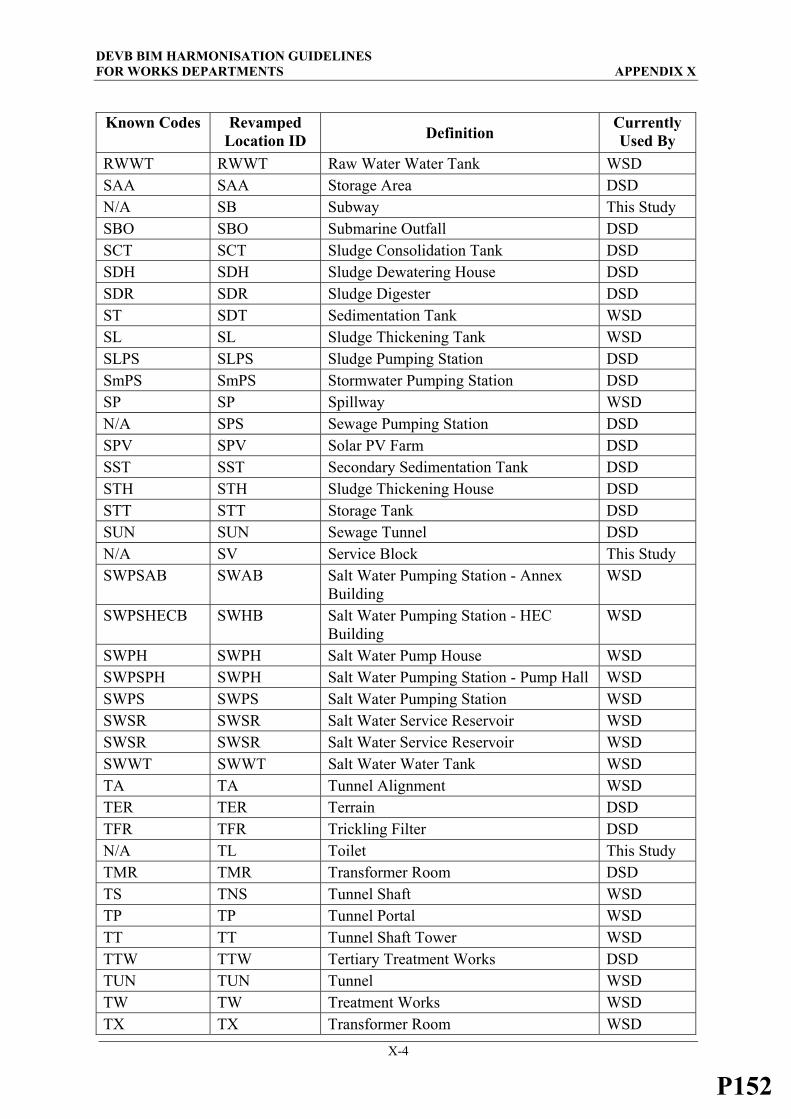
DEVB BIM HARMONISATION GUIDELINES FOR WORKS DEPARTMENTS APPENDIX X
X-4
Known Codes Revamped Location ID Definition Currently
Used By RWWT RWWT Raw Water Water Tank WSD SAA SAA Storage Area DSD N/A SB Subway This Study SBO SBO Submarine Outfall DSD SCT SCT Sludge Consolidation Tank DSD SDH SDH Sludge Dewatering House DSD SDR SDR Sludge Digester DSD ST SDT Sedimentation Tank WSD SL SL Sludge Thickening Tank WSD SLPS SLPS Sludge Pumping Station DSD SmPS SmPS Stormwater Pumping Station DSD SP SP Spillway WSD N/A SPS Sewage Pumping Station DSD SPV SPV Solar PV Farm DSD SST SST Secondary Sedimentation Tank DSD STH STH Sludge Thickening House DSD STT STT Storage Tank DSD SUN SUN Sewage Tunnel DSD N/A SV Service Block This Study SWPSAB SWAB Salt Water Pumping Station - Annex
Building WSD
SWPSHECB SWHB Salt Water Pumping Station - HEC Building
WSD
SWPH SWPH Salt Water Pump House WSD SWPSPH SWPH Salt Water Pumping Station - Pump Hall WSD SWPS SWPS Salt Water Pumping Station WSD SWSR SWSR Salt Water Service Reservoir WSD SWSR SWSR Salt Water Service Reservoir WSD SWWT SWWT Salt Water Water Tank WSD TA TA Tunnel Alignment WSD TER TER Terrain DSD TFR TFR Trickling Filter DSD N/A TL Toilet This Study TMR TMR Transformer Room DSD TS TNS Tunnel Shaft WSD TP TP Tunnel Portal WSD TT TT Tunnel Shaft Tower WSD TTW TTW Tertiary Treatment Works DSD TUN TUN Tunnel WSD TW TW Treatment Works WSD TX TX Transformer Room WSD
P152
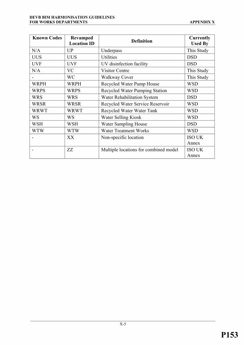
DEVB BIM HARMONISATION GUIDELINES FOR WORKS DEPARTMENTS APPENDIX X
X-5
Known Codes Revamped Location ID Definition Currently
Used By N/A UP Underpass This Study UUS UUS Utilities DSD UVF UVF UV disinfection facility DSD N/A VC Visitor Centre This Study - WC Walkway Cover This Study WRPH WRPH Recycled Water Pump House WSD WRPS WRPS Recycled Water Pumping Station WSD WRS WRS Water Rehabilitation System DSD WRSR WRSR Recycled Water Service Reservoir WSD WRWT WRWT Recycled Water Water Tank WSD WS WS Water Selling Kiosk WSD WSH WSH Water Sampling House DSD WTW WTW Water Treatment Works WSD - XX Non-specific location ISO UK
Annex - ZZ Multiple locations for combined model ISO UK
Annex
P153
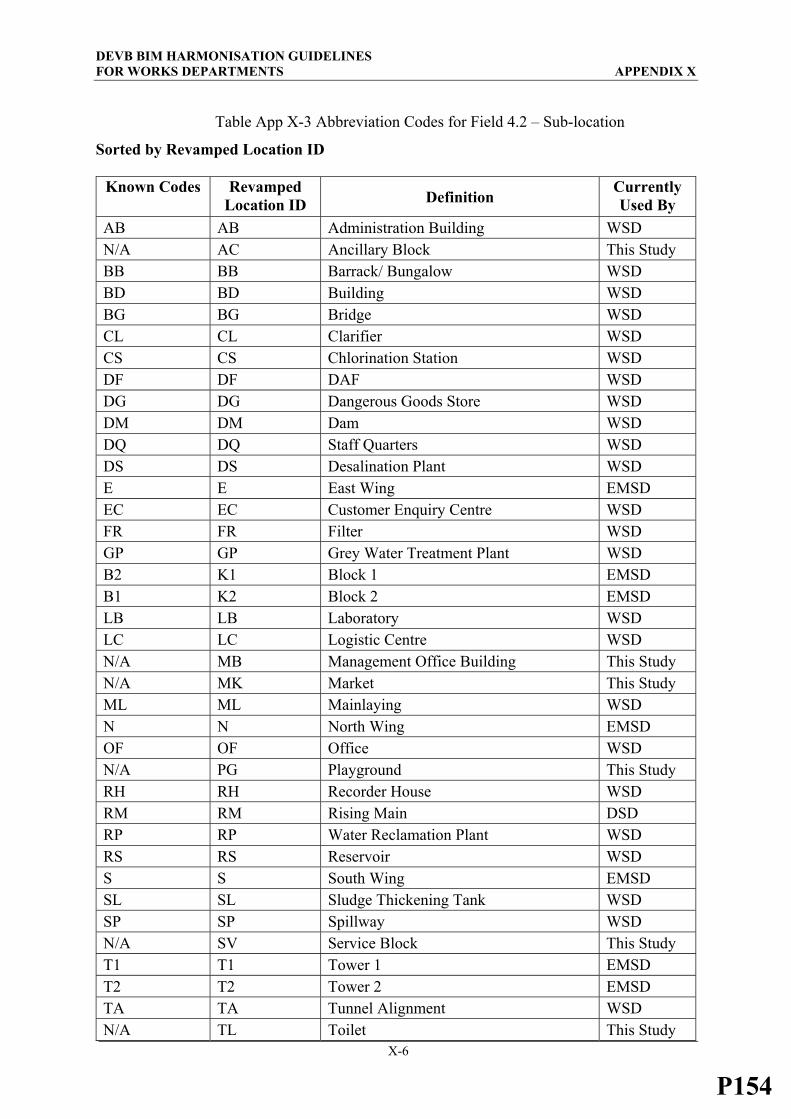
DEVB BIM HARMONISATION GUIDELINES FOR WORKS DEPARTMENTS APPENDIX X
X-6
Table App X-3 Abbreviation Codes for Field 4.2 – Sub-location
Sorted by Revamped Location ID
Known Codes Revamped Location ID Definition Currently
Used By AB AB Administration Building WSD N/A AC Ancillary Block This Study BB BB Barrack/ Bungalow WSD BD BD Building WSD BG BG Bridge WSD CL CL Clarifier WSD CS CS Chlorination Station WSD DF DF DAF WSD DG DG Dangerous Goods Store WSD DM DM Dam WSD DQ DQ Staff Quarters WSD DS DS Desalination Plant WSD E E East Wing EMSD EC EC Customer Enquiry Centre WSD FR FR Filter WSD GP GP Grey Water Treatment Plant WSD B2 K1 Block 1 EMSD B1 K2 Block 2 EMSD LB LB Laboratory WSD LC LC Logistic Centre WSD N/A MB Management Office Building This Study N/A MK Market This Study ML ML Mainlaying WSD N N North Wing EMSD OF OF Office WSD N/A PG Playground This Study RH RH Recorder House WSD RM RM Rising Main DSD RP RP Water Reclamation Plant WSD RS RS Reservoir WSD S S South Wing EMSD SL SL Sludge Thickening Tank WSD SP SP Spillway WSD N/A SV Service Block This Study T1 T1 Tower 1 EMSD T2 T2 Tower 2 EMSD TA TA Tunnel Alignment WSD N/A TL Toilet This Study
P154
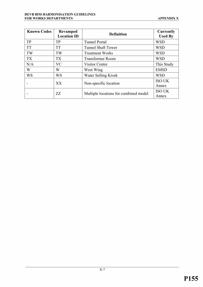
DEVB BIM HARMONISATION GUIDELINES FOR WORKS DEPARTMENTS APPENDIX X
X-7
Known Codes Revamped Location ID Definition Currently
Used By TP TP Tunnel Portal WSD TT TT Tunnel Shaft Tower WSD TW TW Treatment Works WSD TX TX Transformer Room WSD N/A VC Visitor Centre This Study W W West Wing EMSD WS WS Water Selling Kiosk WSD
- XX Non-specific location ISO UK Annex
- ZZ Multiple locations for combined model ISO UK Annex
P155
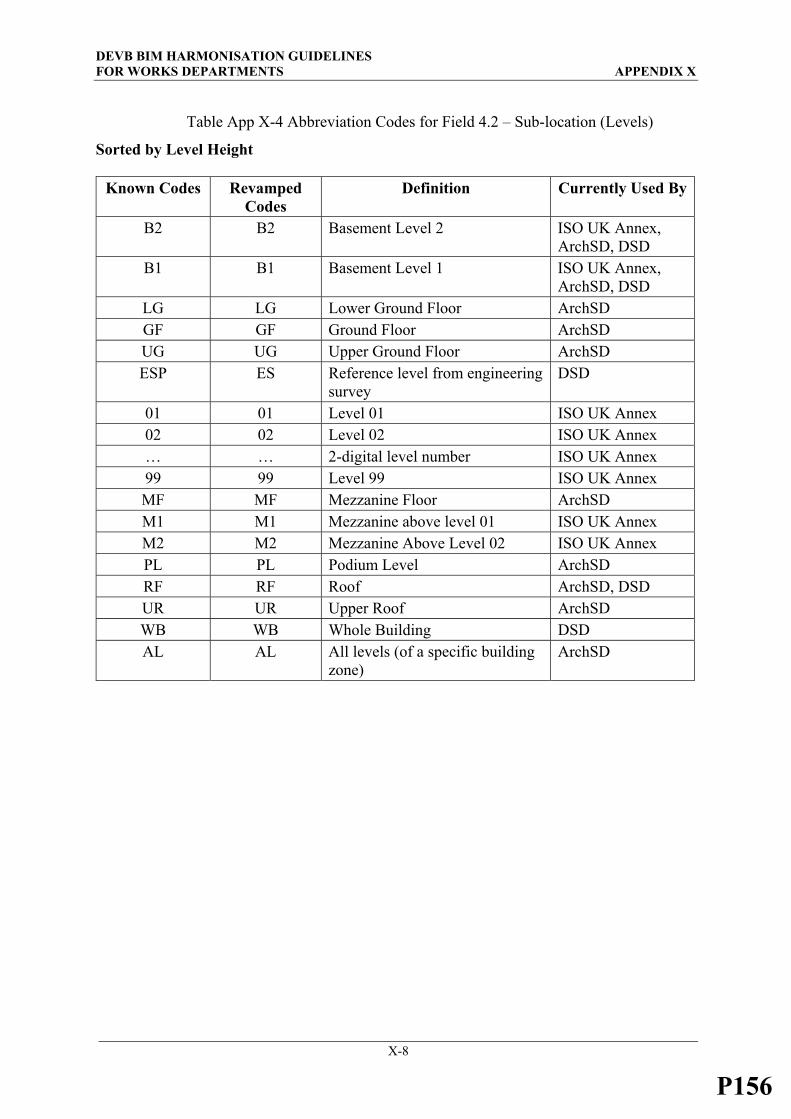
DEVB BIM HARMONISATION GUIDELINES FOR WORKS DEPARTMENTS APPENDIX X
X-8
Table App X-4 Abbreviation Codes for Field 4.2 – Sub-location (Levels)
Sorted by Level Height
Known Codes Revamped Codes
Definition Currently Used By
B2 B2 Basement Level 2 ISO UK Annex, ArchSD, DSD
B1 B1 Basement Level 1 ISO UK Annex, ArchSD, DSD
LG LG Lower Ground Floor ArchSD GF GF Ground Floor ArchSD UG UG Upper Ground Floor ArchSD ESP ES Reference level from engineering
survey DSD
01 01 Level 01 ISO UK Annex 02 02 Level 02 ISO UK Annex … … 2-digital level number ISO UK Annex 99 99 Level 99 ISO UK Annex MF MF Mezzanine Floor ArchSD M1 M1 Mezzanine above level 01 ISO UK Annex M2 M2 Mezzanine Above Level 02 ISO UK Annex PL PL Podium Level ArchSD RF RF Roof ArchSD, DSD UR UR Upper Roof ArchSD WB WB Whole Building DSD AL AL All levels (of a specific building
zone) ArchSD
P156
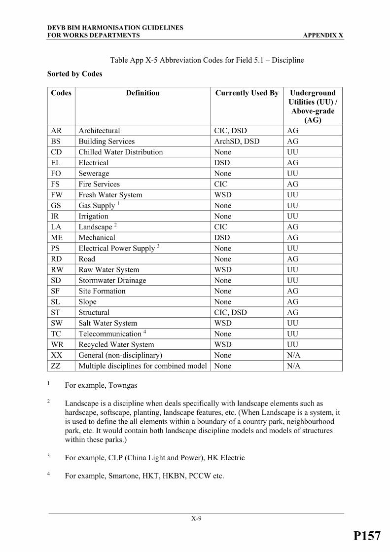
DEVB BIM HARMONISATION GUIDELINES FOR WORKS DEPARTMENTS APPENDIX X
X-9
Table App X-5 Abbreviation Codes for Field 5.1 – Discipline
Sorted by Codes
Codes Definition Currently Used By Underground Utilities (UU) / Above-grade
(AG) AR Architectural CIC, DSD AG BS Building Services ArchSD, DSD AG CD Chilled Water Distribution None UU EL Electrical DSD AG FO Sewerage None UU FS Fire Services CIC AG FW Fresh Water System WSD UU GS Gas Supply 1 None UU IR Irrigation None UU LA Landscape 2 CIC AG ME Mechanical DSD AG PS Electrical Power Supply 3 None UU RD Road None AG RW Raw Water System WSD UU SD Stormwater Drainage None UU SF Site Formation None AG SL Slope None AG ST Structural CIC, DSD AG SW Salt Water System WSD UU TC Telecommunication 4 None UU WR Recycled Water System WSD UU XX General (non-disciplinary) None N/A ZZ Multiple disciplines for combined model None N/A
1 For example, Towngas 2 Landscape is a discipline when deals specifically with landscape elements such as
hardscape, softscape, planting, landscape features, etc. (When Landscape is a system, it is used to define the all elements within a boundary of a country park, neighbourhood park, etc. It would contain both landscape discipline models and models of structures within these parks.)
3 For example, CLP (China Light and Power), HK Electric 4 For example, Smartone, HKT, HKBN, PCCW etc.
P157
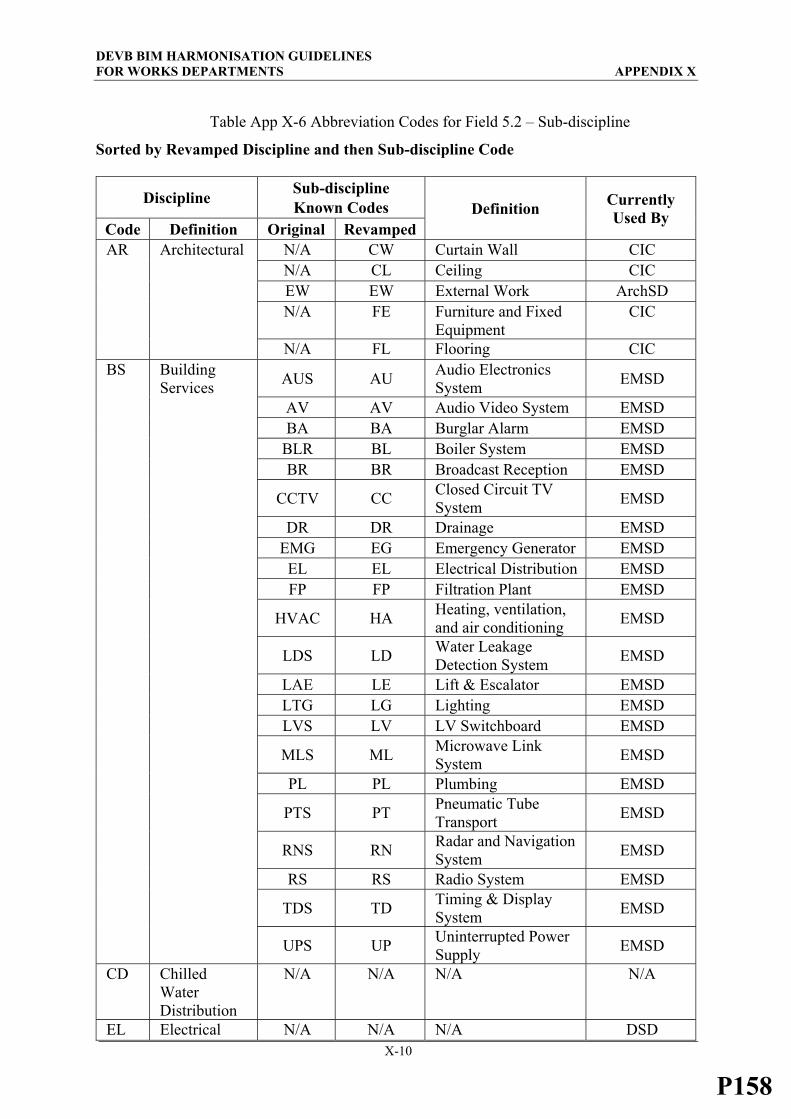
DEVB BIM HARMONISATION GUIDELINES FOR WORKS DEPARTMENTS APPENDIX X
X-10
Table App X-6 Abbreviation Codes for Field 5.2 – Sub-discipline
Sorted by Revamped Discipline and then Sub-discipline Code
Discipline Sub-discipline Known Codes Definition
Currently Used By
Code Definition Original Revamped AR Architectural N/A CW Curtain Wall CIC
N/A CL Ceiling CIC EW EW External Work ArchSD N/A FE Furniture and Fixed
Equipment CIC
N/A FL Flooring CIC BS Building
Services AUS AU Audio Electronics System EMSD
AV AV Audio Video System EMSD BA BA Burglar Alarm EMSD
BLR BL Boiler System EMSD BR BR Broadcast Reception EMSD
CCTV CC Closed Circuit TV System EMSD
DR DR Drainage EMSD EMG EG Emergency Generator EMSD EL EL Electrical Distribution EMSD FP FP Filtration Plant EMSD
HVAC HA Heating, ventilation, and air conditioning EMSD
LDS LD Water Leakage Detection System EMSD
LAE LE Lift & Escalator EMSD LTG LG Lighting EMSD LVS LV LV Switchboard EMSD
MLS ML Microwave Link System EMSD
PL PL Plumbing EMSD
PTS PT Pneumatic Tube Transport EMSD
RNS RN Radar and Navigation System EMSD
RS RS Radio System EMSD
TDS TD Timing & Display System EMSD
UPS UP Uninterrupted Power Supply EMSD
CD Chilled Water Distribution
N/A N/A N/A N/A
EL Electrical N/A N/A N/A DSD
P158
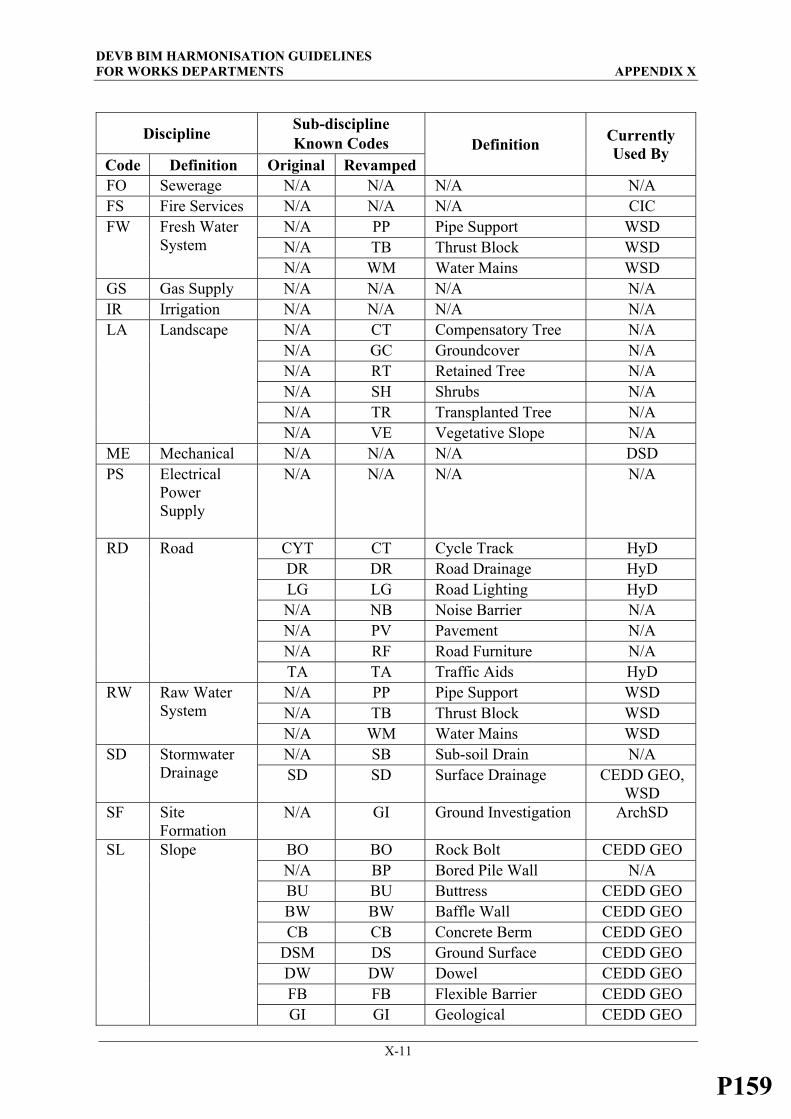
DEVB BIM HARMONISATION GUIDELINES FOR WORKS DEPARTMENTS APPENDIX X
X-11
Discipline Sub-discipline Known Codes Definition
Currently Used By
Code Definition Original Revamped FO Sewerage N/A N/A N/A N/A FS Fire Services N/A N/A N/A CIC FW Fresh Water
System N/A PP Pipe Support WSD N/A TB Thrust Block WSD N/A WM Water Mains WSD
GS Gas Supply N/A N/A N/A N/A IR Irrigation N/A N/A N/A N/A LA Landscape N/A CT Compensatory Tree N/A
N/A GC Groundcover N/A N/A RT Retained Tree N/A N/A SH Shrubs N/A N/A TR Transplanted Tree N/A N/A VE Vegetative Slope N/A
ME Mechanical N/A N/A N/A DSD PS Electrical
Power Supply
N/A N/A N/A N/A
RD Road CYT CT Cycle Track HyD DR DR Road Drainage HyD LG LG Road Lighting HyD N/A NB Noise Barrier N/A N/A PV Pavement N/A N/A RF Road Furniture N/A TA TA Traffic Aids HyD
RW Raw Water System
N/A PP Pipe Support WSD N/A TB Thrust Block WSD N/A WM Water Mains WSD
SD Stormwater Drainage
N/A SB Sub-soil Drain N/A SD SD Surface Drainage CEDD GEO,
WSD SF Site
Formation N/A GI Ground Investigation ArchSD
SL Slope BO BO Rock Bolt CEDD GEO N/A BP Bored Pile Wall N/A BU BU Buttress CEDD GEO BW BW Baffle Wall CEDD GEO CB CB Concrete Berm CEDD GEO
DSM DS Ground Surface CEDD GEO DW DW Dowel CEDD GEO FB FB Flexible Barrier CEDD GEO GI GI Geological CEDD GEO
P159
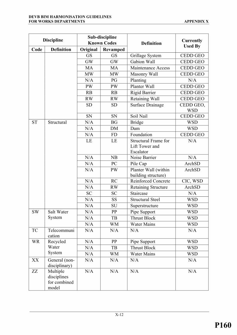
DEVB BIM HARMONISATION GUIDELINES FOR WORKS DEPARTMENTS APPENDIX X
X-12
Discipline Sub-discipline Known Codes Definition
Currently Used By
Code Definition Original Revamped GS GS Grillage System CEDD GEO GW GW Gabion Wall CEDD GEO MA MA Maintenance Access CEDD GEO MW MW Masonry Wall CEDD GEO N/A PG Planting N/A PW PW Planter Wall CEDD GEO RB RB Rigid Barrier CEDD GEO RW RW Retaining Wall CEDD GEO SD SD Surface Drainage CEDD GEO,
WSD SN SN Soil Nail CEDD GEO
ST Structural N/A BG Bridge WSD N/A DM Dam WSD N/A FD Foundation CEDD GEO LE LE Structural Frame for
Lift Tower and Escalator
N/A
N/A NB Noise Barrier N/A N/A PC Pile Cap ArchSD N/A PW Planter Wall (within
building structure) ArchSD
N/A RC Reinforced Concrete CIC, WSD N/A RW Retaining Structure ArchSD SC SC Staircase N/A N/A SS Structural Steel WSD N/A SU Superstructure WSD
SW Salt Water System
N/A PP Pipe Support WSD N/A TB Thrust Block WSD N/A WM Water Mains WSD
TC Telecommunication
N/A N/A N/A N/A
WR Recycled Water System
N/A PP Pipe Support WSD N/A TB Thrust Block WSD N/A WM Water Mains WSD
XX General (non-disciplinary)
N/A N/A N/A N/A
ZZ Multiple disciplines for combined model
N/A N/A N/A N/A
P160
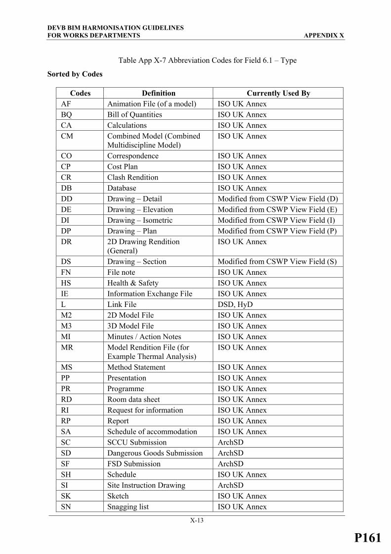
DEVB BIM HARMONISATION GUIDELINES FOR WORKS DEPARTMENTS APPENDIX X
X-13
Table App X-7 Abbreviation Codes for Field 6.1 – Type
Sorted by Codes Codes Definition Currently Used By
AF Animation File (of a model) ISO UK Annex BQ Bill of Quantities ISO UK Annex CA Calculations ISO UK Annex CM Combined Model (Combined
Multidiscipline Model) ISO UK Annex
CO Correspondence ISO UK Annex CP Cost Plan ISO UK Annex CR Clash Rendition ISO UK Annex DB Database ISO UK Annex DD Drawing – Detail Modified from CSWP View Field (D) DE Drawing – Elevation Modified from CSWP View Field (E) DI Drawing – Isometric Modified from CSWP View Field (I) DP Drawing – Plan Modified from CSWP View Field (P) DR 2D Drawing Rendition
(General) ISO UK Annex
DS Drawing – Section Modified from CSWP View Field (S) FN File note ISO UK Annex HS Health & Safety ISO UK Annex IE Information Exchange File ISO UK Annex L Link File DSD, HyD M2 2D Model File ISO UK Annex M3 3D Model File ISO UK Annex MI Minutes / Action Notes ISO UK Annex MR Model Rendition File (for
Example Thermal Analysis) ISO UK Annex
MS Method Statement ISO UK Annex PP Presentation ISO UK Annex PR Programme ISO UK Annex RD Room data sheet ISO UK Annex RI Request for information ISO UK Annex RP Report ISO UK Annex SA Schedule of accommodation ISO UK Annex SC SCCU Submission ArchSD SD Dangerous Goods Submission ArchSD SF FSD Submission ArchSD SH Schedule ISO UK Annex SI Site Instruction Drawing ArchSD SK Sketch ISO UK Annex SN Snagging list ISO UK Annex
P161
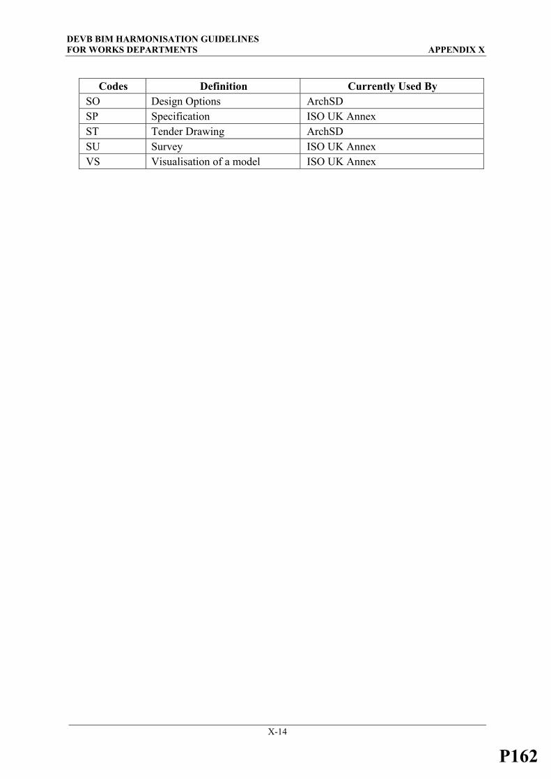
DEVB BIM HARMONISATION GUIDELINES FOR WORKS DEPARTMENTS APPENDIX X
X-14
Codes Definition Currently Used By SO Design Options ArchSD SP Specification ISO UK Annex ST Tender Drawing ArchSD SU Survey ISO UK Annex VS Visualisation of a model ISO UK Annex
P162
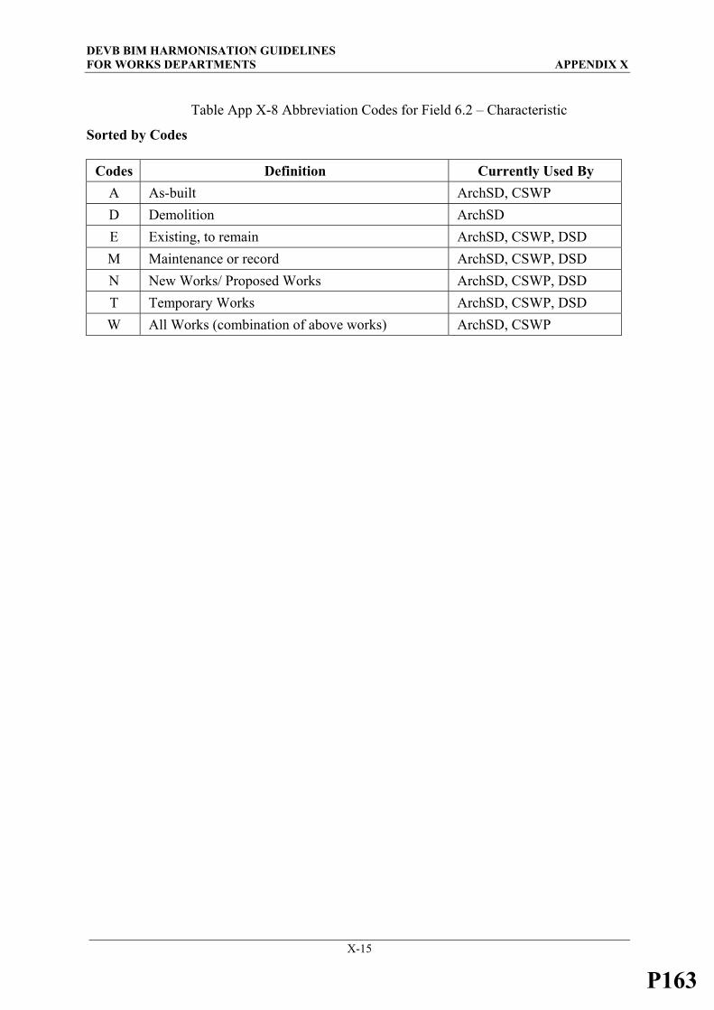
DEVB BIM HARMONISATION GUIDELINES FOR WORKS DEPARTMENTS APPENDIX X
X-15
Table App X-8 Abbreviation Codes for Field 6.2 – Characteristic
Sorted by Codes
Codes Definition Currently Used By
A As-built ArchSD, CSWP D Demolition ArchSD E Existing, to remain ArchSD, CSWP, DSD M Maintenance or record ArchSD, CSWP, DSD N New Works/ Proposed Works ArchSD, CSWP, DSD T Temporary Works ArchSD, CSWP, DSD W All Works (combination of above works) ArchSD, CSWP
P163

DEVB BIM HARMONISATION GUIDELINES FOR WORKS DEPARTMENTS APPENDIX XI
– A Sample Spreadsheet for BIM File Name Validation
P164
DEVB BIM HARMONISATION GUIDELINES FOR WORKS DEPARTMENTS APPENDIX XI
Table of Content
1. Introduction ....................................................................................................................................... XI-1 2. BIM File Name Validation Process Using Spreadsheet .................................................................... XI-1
List of Figures
Figure App XI-1 - The “Project Specified Code” Worksheet ............................................................................ XI-2
Figure App XI-2 –The Worksheets for Each Field ............................................................................................ XI-3
Figure App XI-3 - The “Model Naming” Worksheets ...................................................................................... XI-3
Figure App XI-4 – Example of Drop-Down List for Selecting Codes .............................................................. XI-4
Figure App XI-5 - Example of Auto-Generated Information for Model Files .................................................. XI-4
Figure App XI-6 - Hidden Columns on the “Model Naming” Worksheet ........................................................ XI-5
Figure App XI-7 – Example of Cells with Grey Font Colour............................................................................ XI-5
P165
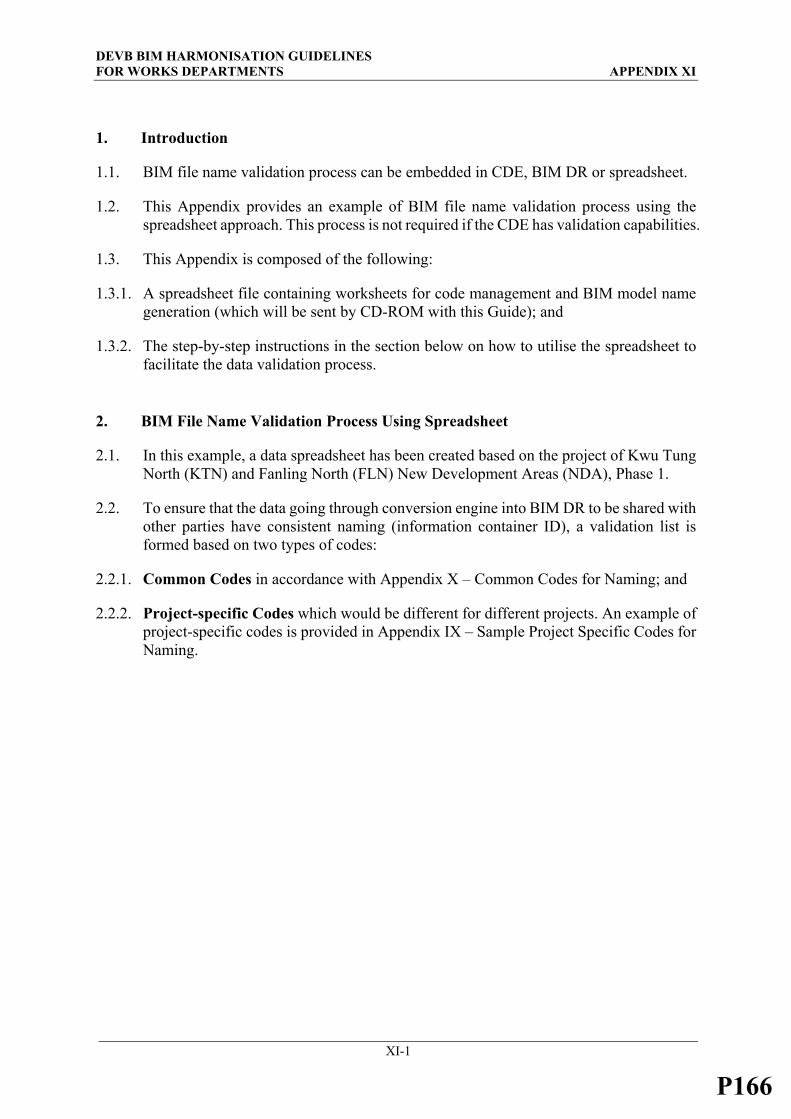
DEVB BIM HARMONISATION GUIDELINES FOR WORKS DEPARTMENTS APPENDIX XI
XI-1
1. Introduction
1.1. BIM file name validation process can be embedded in CDE, BIM DR or spreadsheet.
1.2. This Appendix provides an example of BIM file name validation process using the spreadsheet approach. This process is not required if the CDE has validation capabilities.
1.3. This Appendix is composed of the following:
1.3.1. A spreadsheet file containing worksheets for code management and BIM model name generation (which will be sent by CD-ROM with this Guide); and
1.3.2. The step-by-step instructions in the section below on how to utilise the spreadsheet to facilitate the data validation process.
2. BIM File Name Validation Process Using Spreadsheet
2.1. In this example, a data spreadsheet has been created based on the project of Kwu Tung North (KTN) and Fanling North (FLN) New Development Areas (NDA), Phase 1.
2.2. To ensure that the data going through conversion engine into BIM DR to be shared with other parties have consistent naming (information container ID), a validation list is formed based on two types of codes:
2.2.1. Common Codes in accordance with Appendix X – Common Codes for Naming; and
2.2.2. Project-specific Codes which would be different for different projects. An example of project-specific codes is provided in Appendix IX – Sample Project Specific Codes for Naming.
P166
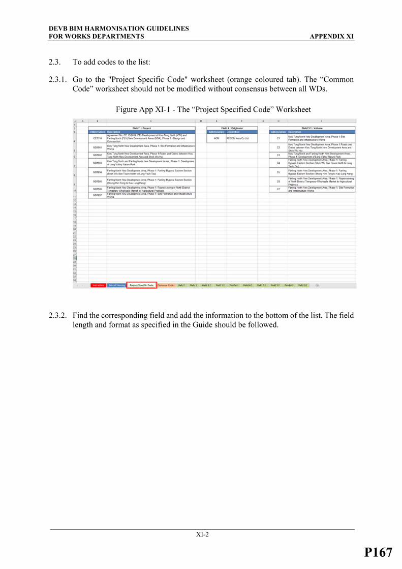
DEVB BIM HARMONISATION GUIDELINES FOR WORKS DEPARTMENTS APPENDIX XI
XI-2
2.3. To add codes to the list:
2.3.1. Go to the "Project Specific Code" worksheet (orange coloured tab). The “Common Code” worksheet should not be modified without consensus between all WDs.
Figure App XI-1 - The “Project Specified Code” Worksheet
2.3.2. Find the corresponding field and add the information to the bottom of the list. The field length and format as specified in the Guide should be followed.
P167
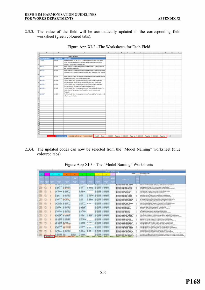
DEVB BIM HARMONISATION GUIDELINES FOR WORKS DEPARTMENTS APPENDIX XI
XI-3
2.3.3. The value of the field will be automatically updated in the corresponding field worksheet (green coloured tabs).
Figure App XI-2 –The Worksheets for Each Field
2.3.4. The updated codes can now be selected from the “Model Naming” worksheet (blue coloured tabs).
Figure App XI-3 - The “Model Naming” Worksheets
P168
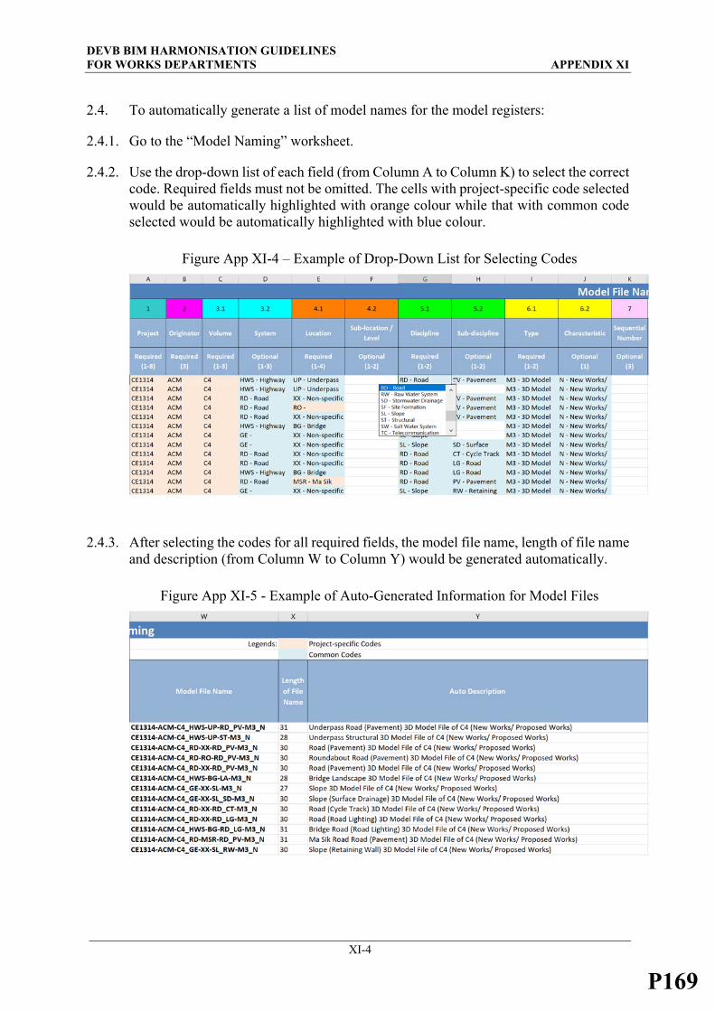
DEVB BIM HARMONISATION GUIDELINES FOR WORKS DEPARTMENTS APPENDIX XI
XI-4
2.4. To automatically generate a list of model names for the model registers:
2.4.1. Go to the “Model Naming” worksheet.
2.4.2. Use the drop-down list of each field (from Column A to Column K) to select the correct code. Required fields must not be omitted. The cells with project-specific code selected would be automatically highlighted with orange colour while that with common code selected would be automatically highlighted with blue colour.
Figure App XI-4 – Example of Drop-Down List for Selecting Codes
2.4.3. After selecting the codes for all required fields, the model file name, length of file name and description (from Column W to Column Y) would be generated automatically.
Figure App XI-5 - Example of Auto-Generated Information for Model Files
P169
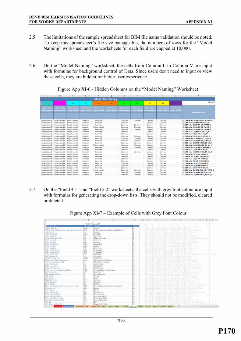
DEVB BIM HARMONISATION GUIDELINES FOR WORKS DEPARTMENTS APPENDIX XI
XI-5
2.5. The limitations of the sample spreadsheet for BIM file name validation should be noted. To keep this spreadsheet’s file size manageable, the numbers of rows for the “Model Naming” worksheet and the worksheets for each field are capped at 10,000.
2.6. On the “Model Naming” worksheet, the cells from Column L to Column V are input with formulas for background control of Data. Since users don't need to input or view these cells, they are hidden for better user experience.
Figure App XI-6 - Hidden Columns on the “Model Naming” Worksheet
2.7. On the “Field 4.1” and “Field 5.2” worksheets, the cells with grey font colour are input with formulas for generating the drop-down lists. They should not be modified, cleared or deleted.
Figure App XI-7 – Example of Cells with Grey Font Colour
P170
DEVB BIM HARMONISATION GUIDELINES FOR WORKS DEPARTMENTS APPENDIX XII
– Mapping Table for Information Container ID Fields –
ArchSD
P171
DEVB BIM HARMONISATION GUIDELINES FOR WORKS DEPARTMENTS APPENDIX XII
TABLE OF CONTENTS
1. ArchSD - Architectural Design ....................................................................................................... XII-1 Fields Mapping Table ...................................................................................................................... XII-1 Fields Mapping Diagram ................................................................................................................. XII-3 Fields that match with this Guide .................................................................................................... XII-4 Fields that Needs to be Mapped ...................................................................................................... XII-4
2. ArchSD – Building Services Installation......................................................................................... XII-5 Fields Mapping Table ...................................................................................................................... XII-5 Fields Mapping Diagram ................................................................................................................. XII-7 ArchSD’s Fields that Match with this Guide ................................................................................... XII-8 ArchSD’s Fields that Needs to be Mapped ..................................................................................... XII-8
3. ArchSD – Structural Engineering .................................................................................................. XII-10 Fields Mapping Table .................................................................................................................... XII-10 Fields Mapping Diagram ............................................................................................................... XII-12 Fields that Match with this Guide ................................................................................................. XII-13 Fields that Needs to be Mapped .................................................................................................... XII-13
List of Tables
Table App XII-1 Field Mapping for ArchSD AR Guide ............................................................................... XII-1
Table App XII-2 Code Mapping for ArchSD AR Guide ............................................................................... XII-4
Table App XII-3 Field Mapping for ArchSD BS Guide ................................................................................ XII-5
Table App XII-4 Codes Mapping for ArchSD BS Guide .............................................................................. XII-8
Table App XII-5 Field Mapping for ArchSD SE Guide .............................................................................. XII-10
Table App XII-6 Codes Mapping for ArchSD SE Guide ............................................................................ XII-13
List of Figures
Figure App XII-1 Field Mapping Diagram for ArchSD AR Guide ............................................................... XII-3
Figure App XII-2 Field Mapping Diagram for ArchSD BS Guide ............................................................... XII-7
Figure App XII-3 Field Mapping Diagram for ArchSD SE Guide .............................................................. XII-12
P172
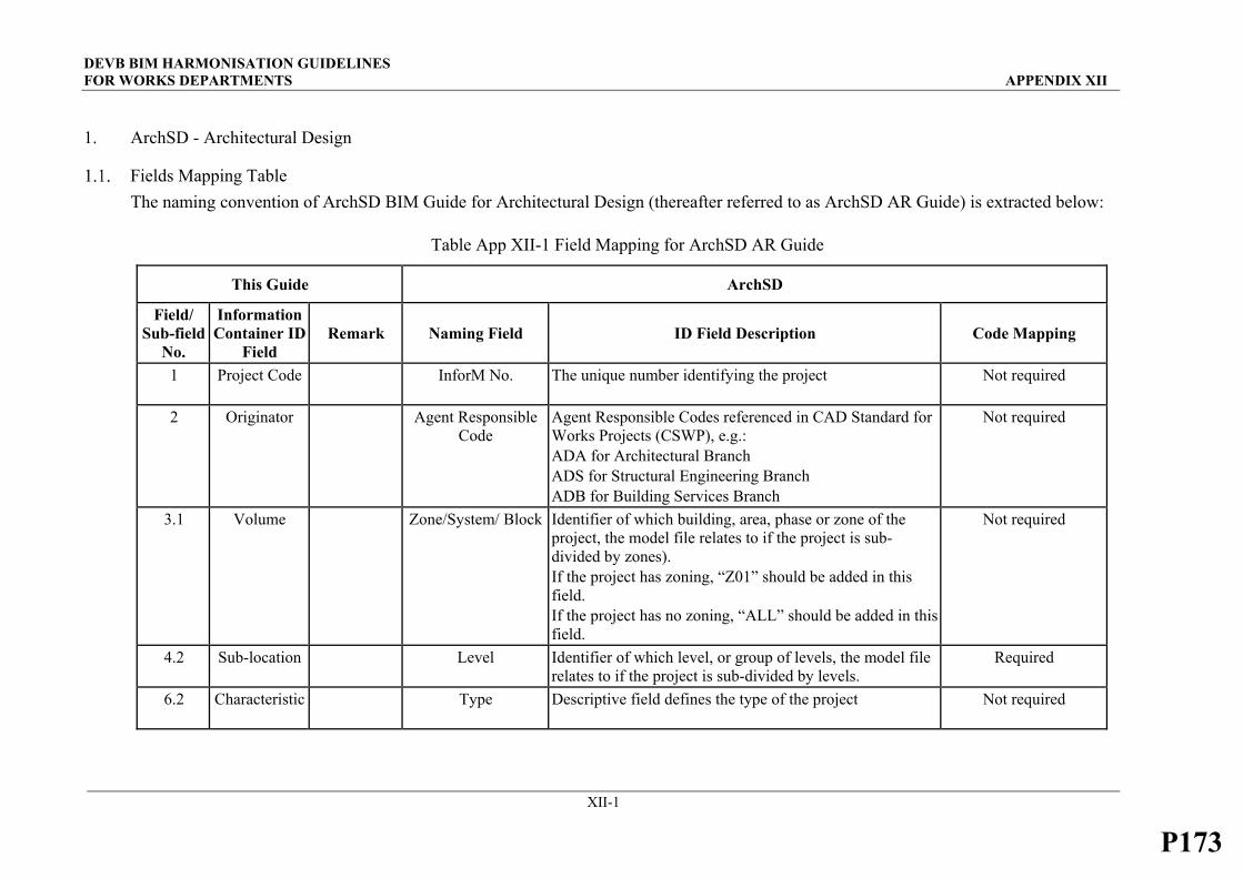
DEVB BIM HARMONISATION GUIDELINES FOR WORKS DEPARTMENTS APPENDIX XII
XII-1
1. ArchSD - Architectural Design
Fields Mapping Table The naming convention of ArchSD BIM Guide for Architectural Design (thereafter referred to as ArchSD AR Guide) is extracted below:
Table App XII-1 Field Mapping for ArchSD AR Guide
This Guide ArchSD
Field/ Sub-field
No.
Information Container ID
Field Remark Naming Field ID Field Description Code Mapping
1 Project Code InforM No. The unique number identifying the project Not required
2 Originator Agent Responsible Code
Agent Responsible Codes referenced in CAD Standard for Works Projects (CSWP), e.g.: ADA for Architectural Branch ADS for Structural Engineering Branch ADB for Building Services Branch
Not required
3.1 Volume Zone/System/ Block Identifier of which building, area, phase or zone of the project, the model file relates to if the project is sub-divided by zones). If the project has zoning, “Z01” should be added in this field. If the project has no zoning, “ALL” should be added in this field.
Not required
4.2 Sub-location Level Identifier of which level, or group of levels, the model file relates to if the project is sub-divided by levels.
Required
6.2 Characteristic Type Descriptive field defines the type of the project Not required
P173
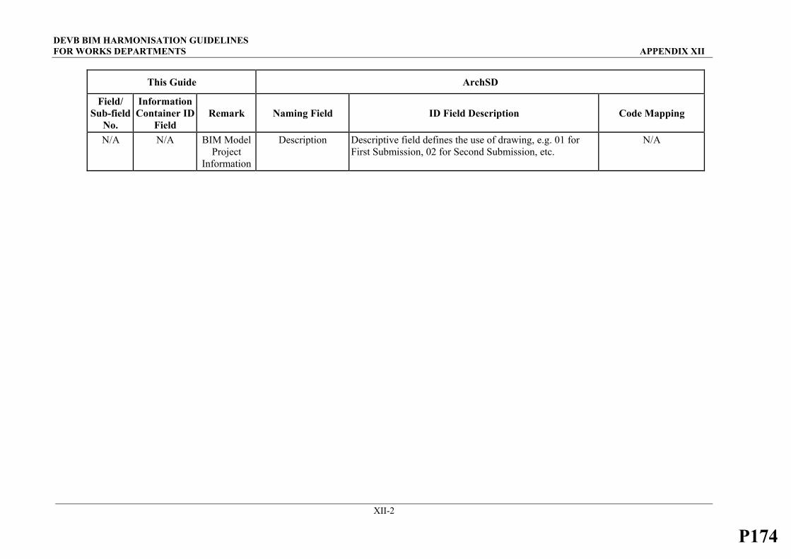
DEVB BIM HARMONISATION GUIDELINES FOR WORKS DEPARTMENTS APPENDIX XII
XII-2
This Guide ArchSD
Field/ Sub-field
No.
Information Container ID
Field Remark Naming Field ID Field Description Code Mapping
N/A N/A BIM Model Project
Information
Description Descriptive field defines the use of drawing, e.g. 01 for First Submission, 02 for Second Submission, etc.
N/A
P174
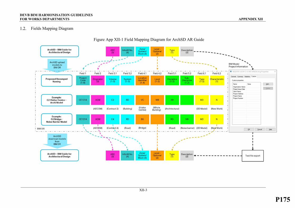
DEVB BIM HARMONISATION GUIDELINES FOR WORKS DEPARTMENTS APPENDIX XII
XII-3
Fields Mapping Diagram
Figure App XII-1 Field Mapping Diagram for ArchSD AR Guide
P175
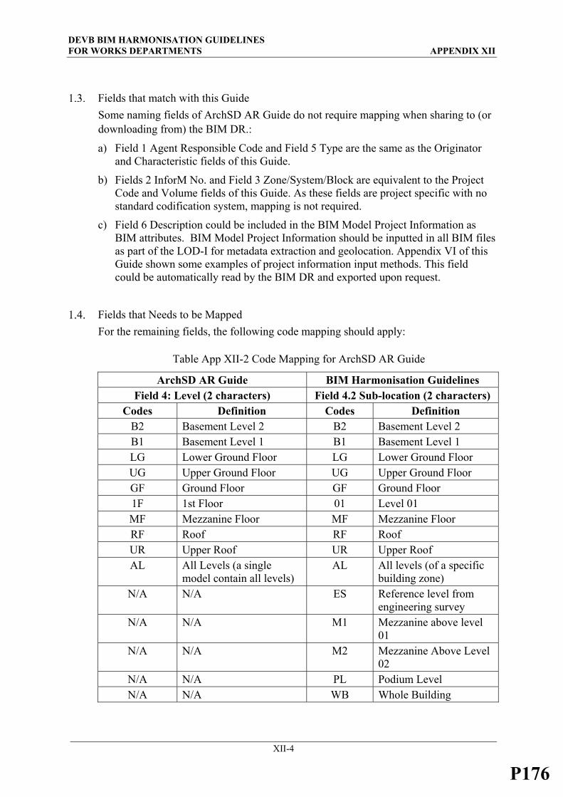
DEVB BIM HARMONISATION GUIDELINES FOR WORKS DEPARTMENTS APPENDIX XII
XII-4
Fields that match with this Guide Some naming fields of ArchSD AR Guide do not require mapping when sharing to (or downloading from) the BIM DR.:
a) Field 1 Agent Responsible Code and Field 5 Type are the same as the Originator and Characteristic fields of this Guide.
b) Fields 2 InforM No. and Field 3 Zone/System/Block are equivalent to the Project Code and Volume fields of this Guide. As these fields are project specific with no standard codification system, mapping is not required.
c) Field 6 Description could be included in the BIM Model Project Information as BIM attributes. BIM Model Project Information should be inputted in all BIM files as part of the LOD-I for metadata extraction and geolocation. Appendix VI of this Guide shown some examples of project information input methods. This field could be automatically read by the BIM DR and exported upon request.
Fields that Needs to be Mapped For the remaining fields, the following code mapping should apply:
Table App XII-2 Code Mapping for ArchSD AR Guide
ArchSD AR Guide BIM Harmonisation Guidelines Field 4: Level (2 characters) Field 4.2 Sub-location (2 characters)
Codes Definition Codes Definition B2 Basement Level 2 B2 Basement Level 2 B1 Basement Level 1 B1 Basement Level 1 LG Lower Ground Floor LG Lower Ground Floor UG Upper Ground Floor UG Upper Ground Floor GF Ground Floor GF Ground Floor 1F 1st Floor 01 Level 01 MF Mezzanine Floor MF Mezzanine Floor RF Roof RF Roof UR Upper Roof UR Upper Roof AL All Levels (a single
model contain all levels) AL All levels (of a specific
building zone) N/A N/A ES Reference level from
engineering survey N/A N/A M1 Mezzanine above level
01 N/A N/A M2 Mezzanine Above Level
02 N/A N/A PL Podium Level N/A N/A WB Whole Building
P176
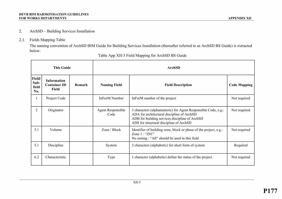
DEVB BIM HARMONISATION GUIDELINES FOR WORKS DEPARTMENTS APPENDIX XII
XII-5
2. ArchSD – Building Services Installation
Fields Mapping Table The naming convention of ArchSD BIM Guide for Building Services Installation (thereafter referred to as ArchSD BS Guide) is extracted below:
Table App XII-3 Field Mapping for ArchSD BS Guide
This Guide ArchSD
Field/ Sub-field No.
Information Container ID
Field Remark Naming Field Field Description Code Mapping
1 Project Code InForM Number InForM number of the project Not required
2 Originator Agent Responsible Code
3 characters (alphanumeric) for Agent Responsible Code, e.g.: ADA for architectural discipline of ArchSD ADB for building services discipline of ArchSD ADS for structural discipline of ArchSD
Not required
3.1 Volume Zone / Block Identifier of building zone, block or phase of the project, e.g.: Zone 1 : “Z01” No zoning : “All” should be used in this field
Not required
5.1 Discipline System 2 characters (alphabetic) for short form of system Required
6.2 Characteristic Type 1 character (alphabetic) define the status of the project Not required
P177
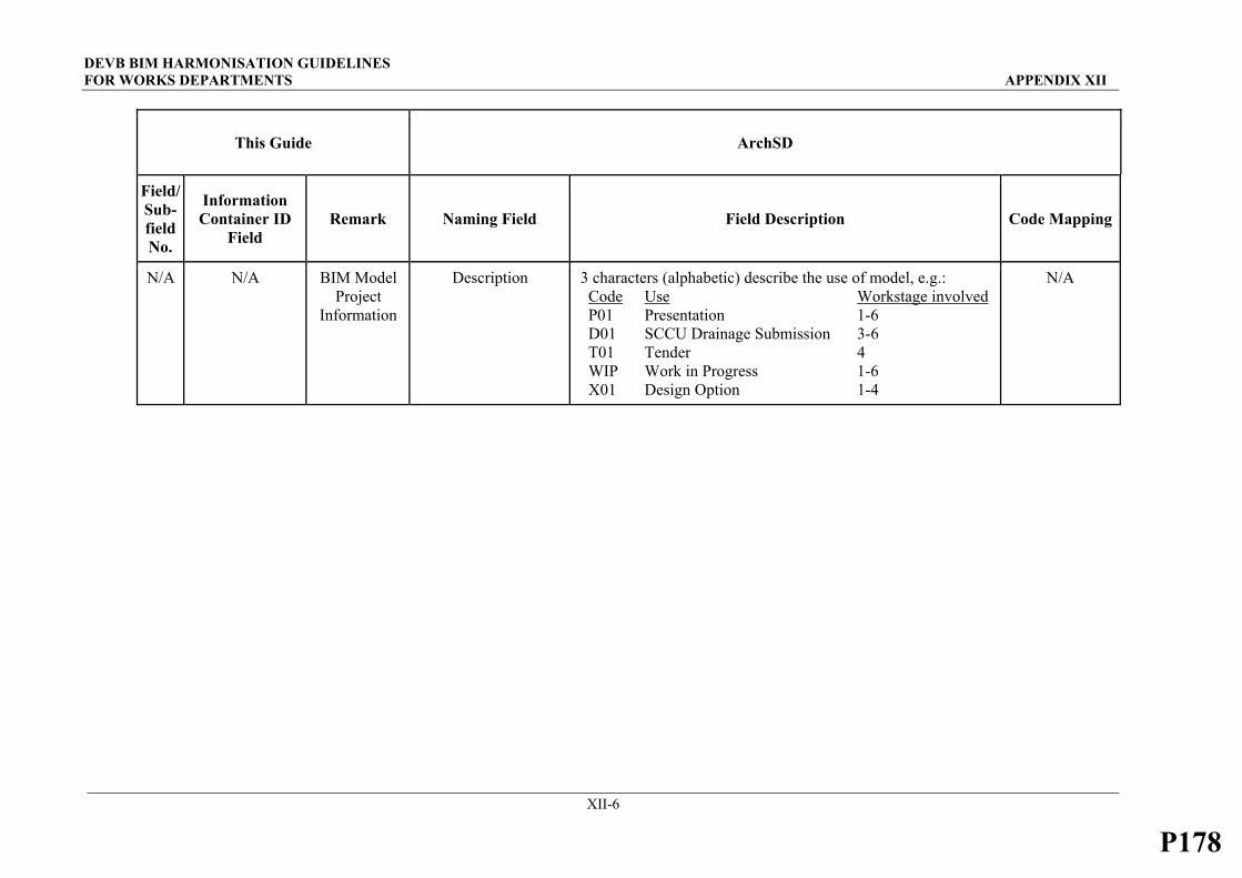
DEVB BIM HARMONISATION GUIDELINES FOR WORKS DEPARTMENTS APPENDIX XII
XII-6
This Guide ArchSD
Field/ Sub-field No.
Information Container ID
Field Remark Naming Field Field Description Code Mapping
N/A N/A BIM Model Project
Information
Description 3 characters (alphabetic) describe the use of model, e.g.: Code Use Workstage involved P01 Presentation 1-6 D01 SCCU Drainage Submission 3-6 T01 Tender 4 WIP Work in Progress 1-6 X01 Design Option 1-4
N/A
P178
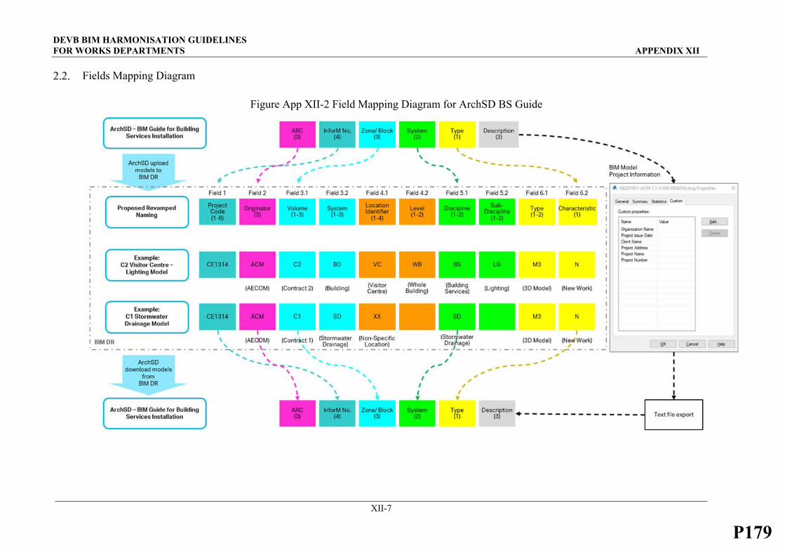
DEVB BIM HARMONISATION GUIDELINES FOR WORKS DEPARTMENTS APPENDIX XII
XII-7
Fields Mapping Diagram
Figure App XII-2 Field Mapping Diagram for ArchSD BS Guide
P179
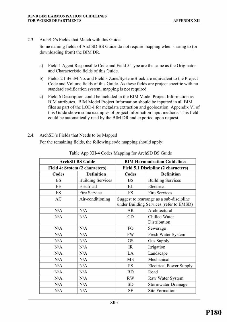
DEVB BIM HARMONISATION GUIDELINES FOR WORKS DEPARTMENTS APPENDIX XII
XII-8
ArchSD’s Fields that Match with this Guide Some naming fields of ArchSD BS Guide do not require mapping when sharing to (or downloading from) the BIM DR.
a) Field 1 Agent Responsible Code and Field 5 Type are the same as the Originator and Characteristic fields of this Guide.
b) Fields 2 InForM No. and Field 3 Zone/System/Block are equivalent to the Project Code and Volume fields of this Guide. As these fields are project specific with no standard codification system, mapping is not required.
c) Field 6 Description could be included in the BIM Model Project Information as BIM attributes. BIM Model Project Information should be inputted in all BIM files as part of the LOD-I for metadata extraction and geolocation. Appendix VI of this Guide shown some examples of project information input methods. This field could be automatically read by the BIM DR and exported upon request.
ArchSD’s Fields that Needs to be Mapped For the remaining fields, the following code mapping should apply:
Table App XII-4 Codes Mapping for ArchSD BS Guide
ArchSD BS Guide BIM Harmonisation Guidelines Field 4: System (2 characters) Field 5.1 Discipline (2 characters)
Codes Definition Codes Definition BS Building Services BS Building Services EE Electrical EL Electrical FS Fire Service FS Fire Services AC Air-conditioning Suggest to rearrange as a sub-discipline
under Building Services (refer to EMSD) N/A N/A AR Architectural N/A N/A CD Chilled Water
Distribution N/A N/A FO Sewerage N/A N/A FW Fresh Water System N/A N/A GS Gas Supply N/A N/A IR Irrigation N/A N/A LA Landscape N/A N/A ME Mechanical N/A N/A PS Electrical Power Supply N/A N/A RD Road N/A N/A RW Raw Water System N/A N/A SD Stormwater Drainage N/A N/A SF Site Formation
P180
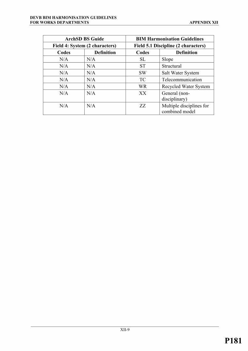
DEVB BIM HARMONISATION GUIDELINES FOR WORKS DEPARTMENTS APPENDIX XII
XII-9
ArchSD BS Guide BIM Harmonisation Guidelines Field 4: System (2 characters) Field 5.1 Discipline (2 characters)
Codes Definition Codes Definition N/A N/A SL Slope N/A N/A ST Structural N/A N/A SW Salt Water System N/A N/A TC Telecommunication N/A N/A WR Recycled Water System N/A N/A XX General (non-
disciplinary) N/A N/A ZZ Multiple disciplines for
combined model
P181
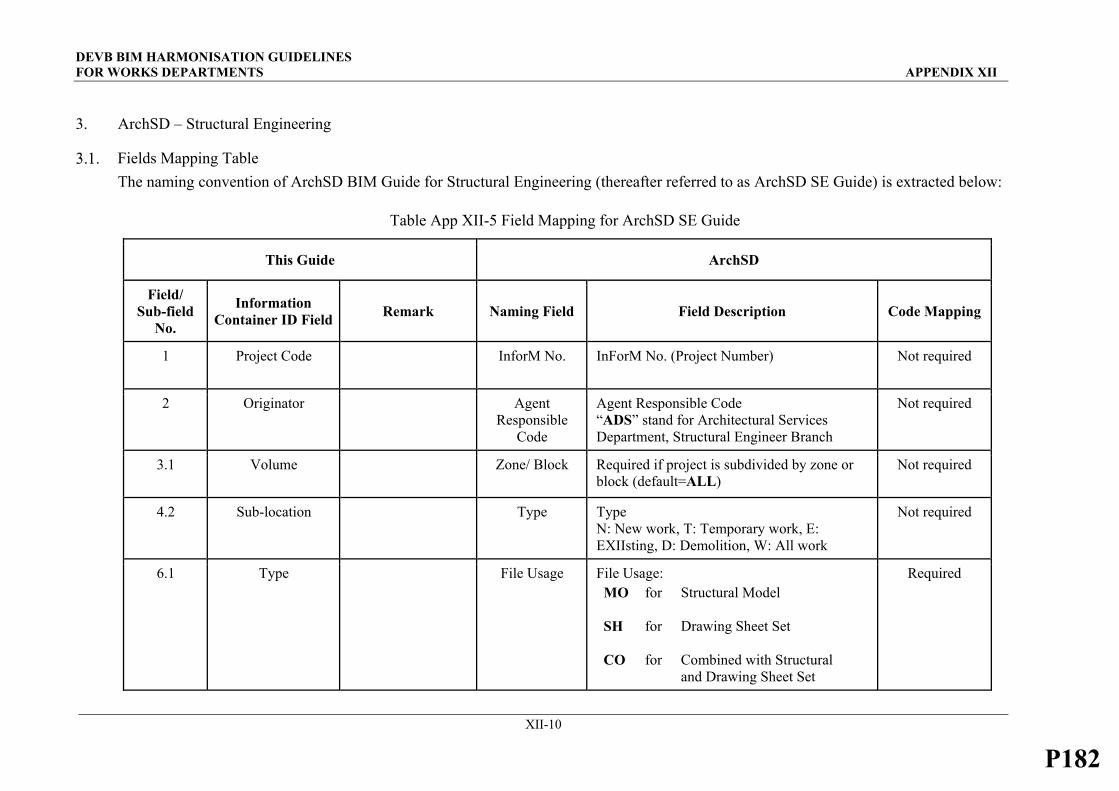
DEVB BIM HARMONISATION GUIDELINES FOR WORKS DEPARTMENTS APPENDIX XII
XII-10
3. ArchSD – Structural Engineering
Fields Mapping Table The naming convention of ArchSD BIM Guide for Structural Engineering (thereafter referred to as ArchSD SE Guide) is extracted below:
Table App XII-5 Field Mapping for ArchSD SE Guide
This Guide ArchSD
Field/ Sub-field
No.
Information Container ID Field
Remark Naming Field Field Description Code Mapping
1 Project Code InforM No. InForM No. (Project Number) Not required
2 Originator Agent Responsible
Code
Agent Responsible Code “ADS” stand for Architectural Services Department, Structural Engineer Branch
Not required
3.1 Volume Zone/ Block Required if project is subdivided by zone or block (default=ALL)
Not required
4.2 Sub-location Type Type N: New work, T: Temporary work, E: EXIIsting, D: Demolition, W: All work
Not required
6.1 Type File Usage File Usage: MO for Structural Model
SH for Drawing Sheet Set
CO for Combined with Structural
and Drawing Sheet Set
Required
P182
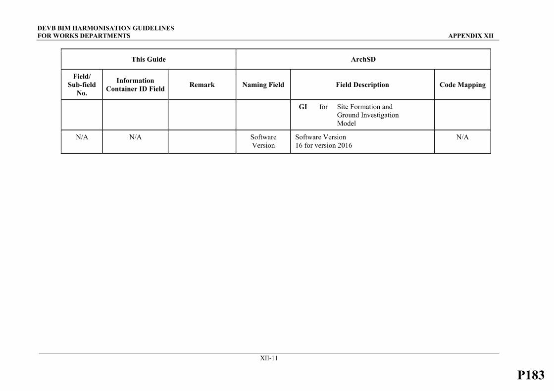
DEVB BIM HARMONISATION GUIDELINES FOR WORKS DEPARTMENTS APPENDIX XII
XII-11
This Guide ArchSD
Field/ Sub-field
No.
Information Container ID Field
Remark Naming Field Field Description Code Mapping
GI for Site Formation and Ground Investigation Model
N/A N/A Software Version
Software Version 16 for version 2016
N/A
P183
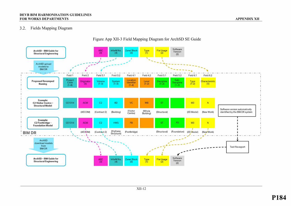
DEVB BIM HARMONISATION GUIDELINES FOR WORKS DEPARTMENTS APPENDIX XII
XII-12
Fields Mapping Diagram
Figure App XII-3 Field Mapping Diagram for ArchSD SE Guide
P184
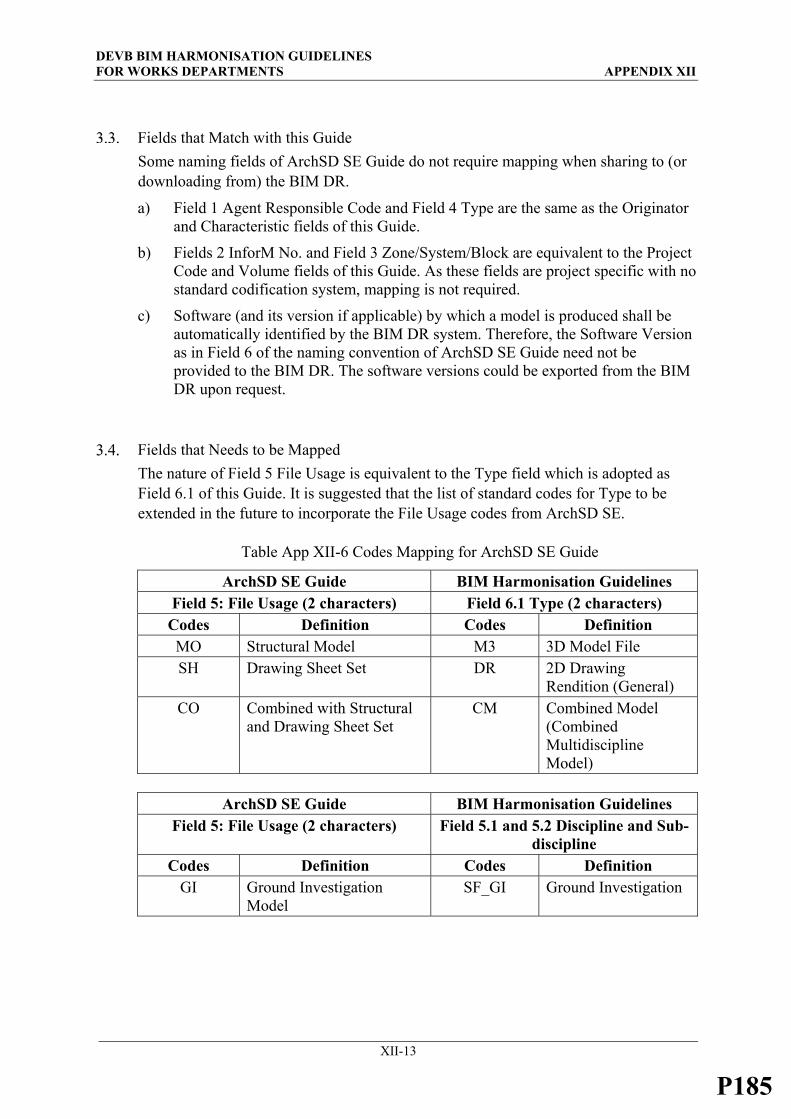
DEVB BIM HARMONISATION GUIDELINES FOR WORKS DEPARTMENTS APPENDIX XII
XII-13
Fields that Match with this Guide Some naming fields of ArchSD SE Guide do not require mapping when sharing to (or downloading from) the BIM DR.
a) Field 1 Agent Responsible Code and Field 4 Type are the same as the Originator and Characteristic fields of this Guide.
b) Fields 2 InforM No. and Field 3 Zone/System/Block are equivalent to the Project Code and Volume fields of this Guide. As these fields are project specific with no standard codification system, mapping is not required.
c) Software (and its version if applicable) by which a model is produced shall be automatically identified by the BIM DR system. Therefore, the Software Version as in Field 6 of the naming convention of ArchSD SE Guide need not be provided to the BIM DR. The software versions could be exported from the BIM DR upon request.
Fields that Needs to be Mapped The nature of Field 5 File Usage is equivalent to the Type field which is adopted as Field 6.1 of this Guide. It is suggested that the list of standard codes for Type to be extended in the future to incorporate the File Usage codes from ArchSD SE.
Table App XII-6 Codes Mapping for ArchSD SE Guide
ArchSD SE Guide BIM Harmonisation Guidelines Field 5: File Usage (2 characters) Field 6.1 Type (2 characters)
Codes Definition Codes Definition MO Structural Model M3 3D Model File SH Drawing Sheet Set DR 2D Drawing
Rendition (General) CO Combined with Structural
and Drawing Sheet Set CM Combined Model
(Combined Multidiscipline Model)
ArchSD SE Guide BIM Harmonisation Guidelines
Field 5: File Usage (2 characters) Field 5.1 and 5.2 Discipline and Sub-discipline
Codes Definition Codes Definition GI Ground Investigation
Model SF_GI Ground Investigation
P185
DEVB BIM HARMONISATION GUIDELINES FOR WORKS DEPARTMENTS APPENDIX XIII
– Mapping Table for Information Container ID Fields –
CEDD GEO
P186
DEVB BIM HARMONISATION GUIDELINES FOR WORKS DEPARTMENTS APPENDIX XIII
TABLE OF CONTENTS 1. CEDD GEO .................................................................................................................................... XIII-1 1.1 Fields Mapping Table ..................................................................................................................... XIII-1 1.2 Fields Mapping Diagram ................................................................................................................ XIII-2 1.3 Fields that matches with this Guide ................................................................................................ XIII-3 1.4 Fields That Needs to be Mapped .................................................................................................... XIII-4
List of Tables
Table App XIII-1 Field Mapping for GEO BIM Manual ............................................................................... XIII-1
Table App XIII-2 Code Mapping for GEO BIM Manual ............................................................................... XIII-4
List of Figures
Figure App XIII-1 Field Mapping Diagram for GEO BIM Manual ............................................................... XIII-2
P187
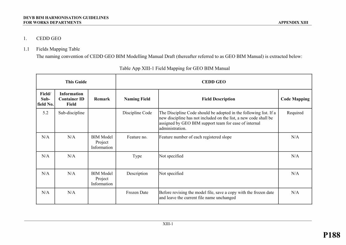
DEVB BIM HARMONISATION GUIDELINES FOR WORKS DEPARTMENTS APPENDIX XIII
XIII-1
1. CEDD GEO
1.1 Fields Mapping Table The naming convention of CEDD GEO BIM Modelling Manual Draft (thereafter referred to as GEO BIM Manual) is extracted below:
Table App XIII-1 Field Mapping for GEO BIM Manual
This Guide CEDD GEO
Field/ Sub-
field No.
Information Container ID
Field Remark Naming Field Field Description Code Mapping
5.2 Sub-discipline Discipline Code The Discipline Code should be adopted in the following list. If a new discipline has not included on the list, a new code shall be assigned by GEO BIM support team for ease of internal administration.
Required
N/A N/A BIM Model Project
Information
Feature no. Feature number of each registered slope N/A
N/A N/A Type Not specified N/A
N/A N/A BIM Model Project
Information
Description Not specified N/A
N/A N/A Frozen Date Before revising the model file, save a copy with the frozen date and leave the current file name unchanged
N/A
P188
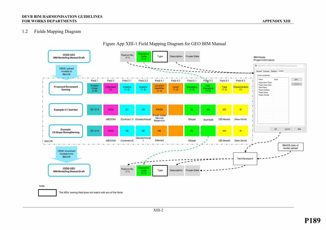
DEVB BIM HARMONISATION GUIDELINES FOR WORKS DEPARTMENTS APPENDIX XIII
XIII-2
1.2 Fields Mapping Diagram
Figure App XIII-1 Field Mapping Diagram for GEO BIM Manual
P189
DEVB BIM HARMONISATION GUIDELINES FOR WORKS DEPARTMENTS APPENDIX XIII
XIII-3
Field 1 Feature No. and Field 3 Type of GEO BIM Manual could not be mapped into any of the information container ID fields due to the following reasons:
a) It is suggested each model file would contain more than one slope within a pre-defined area, instead of one model for one slope. Therefore, slope registration number is not suggested to be included as any part of the information container ID (model file name). Instead, the slope registration numbers for slopes within a model are suggested to be included in the BIM Model Project Information as a BIM attributes which should be inputted in all BIM files as part of the LOD-I for metadata extraction and geolocation. Appendix VI of this Guide shown some examples of project information input methods. This field could be automatically read by the BIM DR and exported upon request.
b) The GEO BIM Manual Draft has not provided the definition for the Type field. However, based on the examples given by CEDD GEO, this field refers to different types of individual elements of a slope, e.g. different types of soil nails. It is suggested that these classifications of elements be handled by BIM objects instead of BIM models. For example, soil nails as BIM objects embedded within a BIM model where different type of soil nails objects may be present within a single model.
1.3 Fields that matches with this Guide Some naming fields of GEO BIM Manual do not require mapping when sharing to (or downloading from) the BIM DR.
a) Field 4 Description shall be included in the BIM Model Project Information as BIM attributes which should be inputted in all BIM files as part of the LOD-I for metadata extraction and geolocation. Appendix VI of this Guide shown some examples of project information input methods. This field could be automatically read by the BIM DR and exported upon request.
b) According to GEO BIM Manual, Field 5 Frozen Date shall be applied when a model file is to be revised, so that a frozen model shall be archived with a frozen date added to its file name. However, models uploaded to the BIM DR are for sharing purpose and are not expected to be revised. Upload dates of the model files shall be recorded by the BIM DR and could be exported upon request.
P190
DEVB BIM HARMONISATION GUIDELINES FOR WORKS DEPARTMENTS APPENDIX XIII
XIII-4
1.4 Fields That Needs to be Mapped For the remaining fields, the following code mapping should apply:
Table App XIII-2 Code Mapping for GEO BIM Manual
GEO BIM Manual BIM Harmonisation Guidelines
Field 2: Discipline Code (2-3 characters)
Field 5.1 Discipline (2 characters)
Field 5.2 Sub-discipline (2 characters)
Codes Definition Codes Definition Codes Definition DSM Digital Surface
Model SL Slope DS Ground Surface
SN Soil Nail SL Slope SN Soil Nail FB Flexible Barrier SL Slope FB Flexible Barrier RB Rigid Barrier SL Slope RB Rigid Barrier UU Underground
Utilities Underground Utilities is not classified as a discipline nor sub-discipline in this Guide. See Appendix VIII for the Federation Strategy related to underground utilities.
SD Surface Drainage SD Stormwater Drainage
SD Surface Drainage
CB Concrete Berm SL Slope CB Concrete Berm MA Maintenance
Access SL Slope MA Maintenance Access
SW Stairway Stairway is not classified as a discipline nor sub-discipline in this Guide. Stairs are suggested to be grouped under Architectural or Structural models.
SF Street Furniture Street Furniture is not classified as a discipline nor sub-discipline in this Guide. Public road furniture may be placed under Road Furniture (RF) model under Road Discipline (RD). Other miscellaneous street furniture are suggested to be grouped under General (non-disciplinary) model (XX).
LS Landscape LA Landscape N/A N/A TE Tree LA Landscape Tree are divided into multiple
sub-disciplines according to the type under Landscape (LA). Details please refer to the Field 5.2 Sub-discipline table.
TR Tree Ring XX General (non-disciplinary)
N/A N/A
GS Grillage System SL Slope GS Grillage System BU Buttress SL Slope BU Buttress DW Dowel SL Slope DW Dowel BO Rock Bolt SL Slope BO Rock Bolt BW Baffle Wall SL Slope BW Baffle Wall GW Gabion Wall SL Slope GW Gabion Wall
P191
DEVB BIM HARMONISATION GUIDELINES FOR WORKS DEPARTMENTS APPENDIX XIII
XIII-5
GEO BIM Manual BIM Harmonisation Guidelines
Field 2: Discipline Code (2-3 characters)
Field 5.1 Discipline (2 characters)
Field 5.2 Sub-discipline (2 characters)
Codes Definition Codes Definition Codes Definition MW Masonry Wall SL Slope MW Masonry Wall PW Planter Wall SL Slope PW Planter Wall RW Retaining Wall SL Slope RW Retaining Wall FD Foundation ST Structural FD Foundation GI Geological SL Slope GI Geological TU Tunnel Tunnel is not classified as a discipline nor sub-discipline in
this Guide. See Appendix VIII for the Federation Strategy related to tunnel (tunnel, subway and underpass).
OT Other Disciplines XX General (non-disciplinary)
N/A N/A
P192

DEVB BIM HARMONISATION GUIDELINES FOR WORKS DEPARTMENTS APPENDIX XIV
– Mapping Table for Information Container ID Fields –
DSD
P193
DEVB BIM HARMONISATION GUIDELINES FOR WORKS DEPARTMENTS APPENDIX XIV
TABLE OF CONTENTS 1. DSD ................................................................................................................................................ XIV-1 1.1. Fields Mapping Table ..................................................................................................................... XIV-1 1.2. Fields Mapping Diagram ................................................................................................................ XIV-3 1.3. Fields that Matches with this Guide ............................................................................................... XIV-4 1.4. Fields that Needs to be Mapped ..................................................................................................... XIV-4
List of Tables
Table App XIV-1 Field Mapping for DSD BIM Manual ............................................................................... XIV-1
Table App XIV-2 Code Mapping for DSD BIM Manual (Discipline) ........................................................... XIV-4
Table App XIV-3 Code Mapping for DSD BIM Manual (Level) .................................................................. XIV-5
Table App XIV-4 Code Mapping for DSD BIM Manual (Characteristic) ..................................................... XIV-6
List of Figures
Figure App XIV-1 Field Mapping Diagram for DSD BIM Manual ............................................................... XIV-3
P194
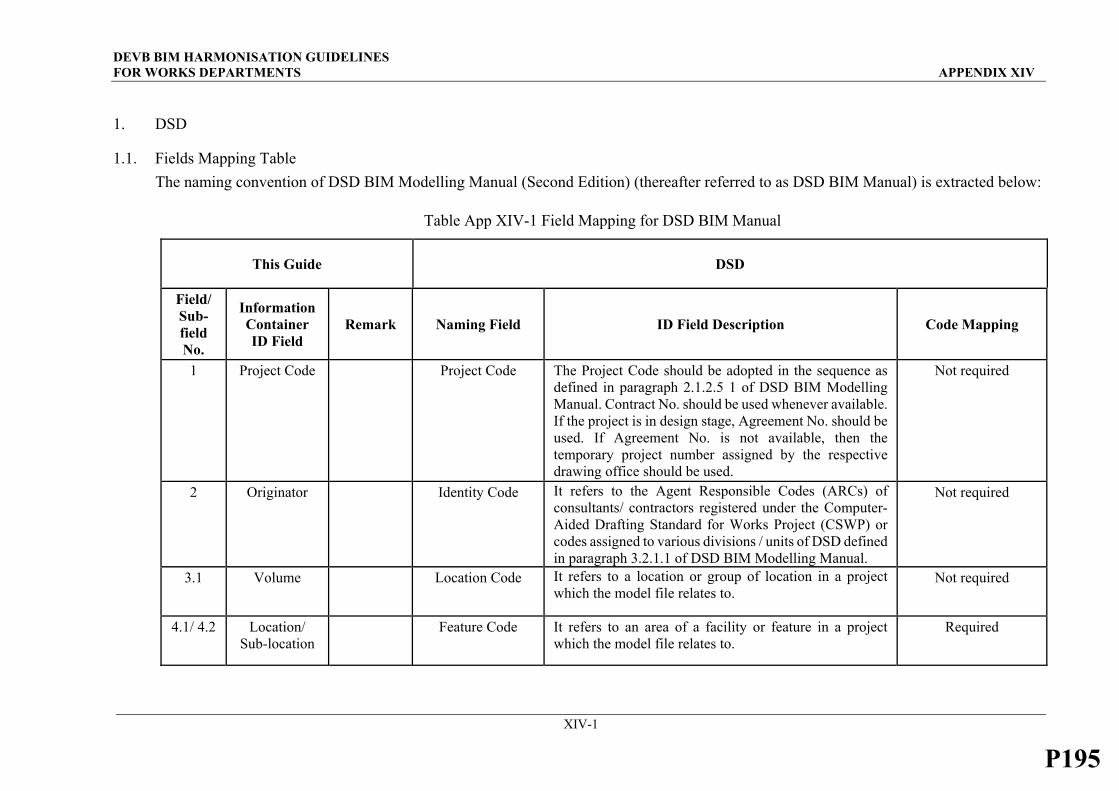
DEVB BIM HARMONISATION GUIDELINES FOR WORKS DEPARTMENTS APPENDIX XIV
XIV-1
1. DSD
1.1. Fields Mapping Table The naming convention of DSD BIM Modelling Manual (Second Edition) (thereafter referred to as DSD BIM Manual) is extracted below:
Table App XIV-1 Field Mapping for DSD BIM Manual
This Guide DSD
Field/ Sub-field No.
Information Container ID Field
Remark Naming Field ID Field Description Code Mapping
1 Project Code Project Code The Project Code should be adopted in the sequence as defined in paragraph 2.1.2.5 1 of DSD BIM Modelling Manual. Contract No. should be used whenever available. If the project is in design stage, Agreement No. should be used. If Agreement No. is not available, then the temporary project number assigned by the respective drawing office should be used.
Not required
2 Originator Identity Code It refers to the Agent Responsible Codes (ARCs) of consultants/ contractors registered under the Computer-Aided Drafting Standard for Works Project (CSWP) or codes assigned to various divisions / units of DSD defined in paragraph 3.2.1.1 of DSD BIM Modelling Manual.
Not required
3.1 Volume Location Code It refers to a location or group of location in a project which the model file relates to.
Not required
4.1/ 4.2 Location/ Sub-location
Feature Code It refers to an area of a facility or feature in a project which the model file relates to.
Required
P195
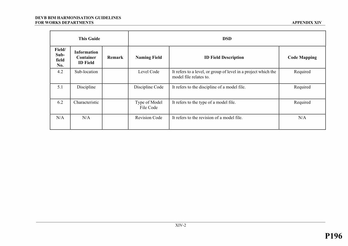
DEVB BIM HARMONISATION GUIDELINES FOR WORKS DEPARTMENTS APPENDIX XIV
XIV-2
This Guide DSD
Field/ Sub-field No.
Information Container ID Field
Remark Naming Field ID Field Description Code Mapping
4.2 Sub-location Level Code It refers to a level, or group of level in a project which the model file relates to.
Required
5.1 Discipline Discipline Code It refers to the discipline of a model file. Required
6.2 Characteristic Type of Model File Code
It refers to the type of a model file. Required
N/A N/A Revision Code It refers to the revision of a model file. N/A
P196
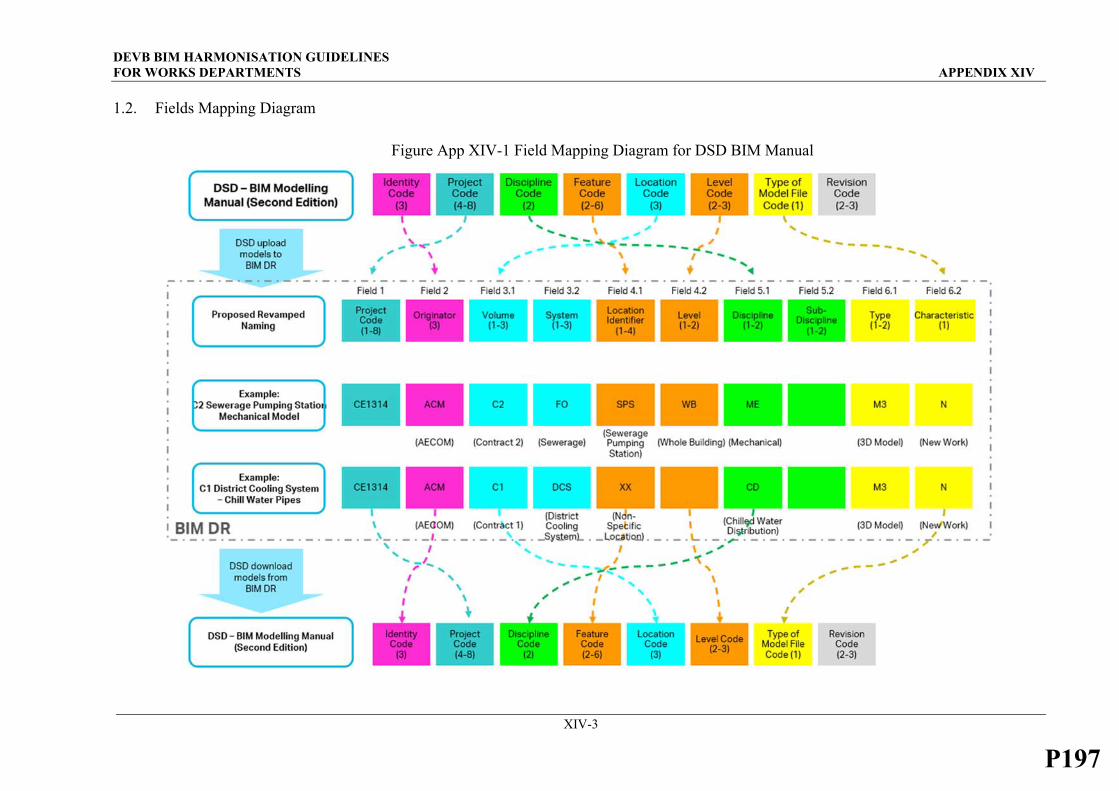
DEVB BIM HARMONISATION GUIDELINES FOR WORKS DEPARTMENTS APPENDIX XIV
XIV-3
1.2. Fields Mapping Diagram
Figure App XIV-1 Field Mapping Diagram for DSD BIM Manual
P197
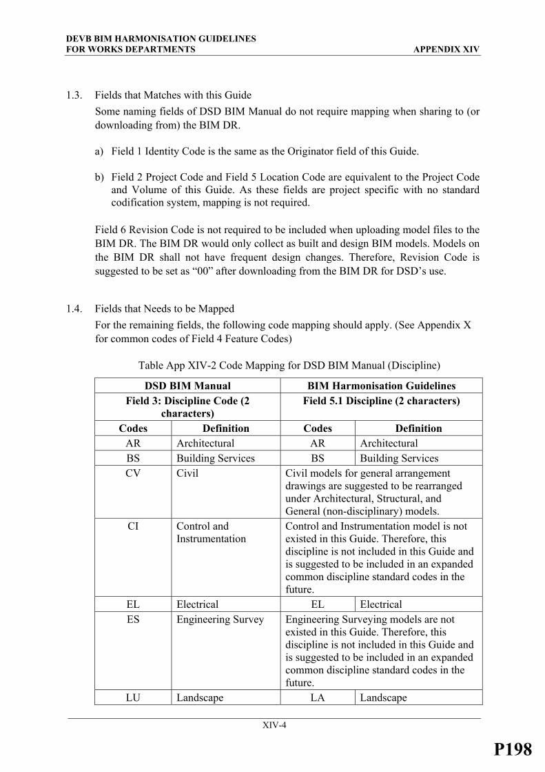
DEVB BIM HARMONISATION GUIDELINES FOR WORKS DEPARTMENTS APPENDIX XIV
XIV-4
1.3. Fields that Matches with this Guide Some naming fields of DSD BIM Manual do not require mapping when sharing to (or downloading from) the BIM DR.
a) Field 1 Identity Code is the same as the Originator field of this Guide.
b) Field 2 Project Code and Field 5 Location Code are equivalent to the Project Code and Volume of this Guide. As these fields are project specific with no standard codification system, mapping is not required.
Field 6 Revision Code is not required to be included when uploading model files to the BIM DR. The BIM DR would only collect as built and design BIM models. Models on the BIM DR shall not have frequent design changes. Therefore, Revision Code is suggested to be set as “00” after downloading from the BIM DR for DSD’s use.
1.4. Fields that Needs to be Mapped For the remaining fields, the following code mapping should apply. (See Appendix X for common codes of Field 4 Feature Codes)
Table App XIV-2 Code Mapping for DSD BIM Manual (Discipline)
DSD BIM Manual BIM Harmonisation Guidelines Field 3: Discipline Code (2
characters) Field 5.1 Discipline (2 characters)
Codes Definition Codes Definition AR Architectural AR Architectural BS Building Services BS Building Services CV Civil Civil models for general arrangement
drawings are suggested to be rearranged under Architectural, Structural, and General (non-disciplinary) models.
CI Control and Instrumentation
Control and Instrumentation model is not existed in this Guide. Therefore, this discipline is not included in this Guide and is suggested to be included in an expanded common discipline standard codes in the future.
EL Electrical EL Electrical ES Engineering Survey Engineering Surveying models are not
existed in this Guide. Therefore, this discipline is not included in this Guide and is suggested to be included in an expanded common discipline standard codes in the future.
LU Landscape LA Landscape
P198
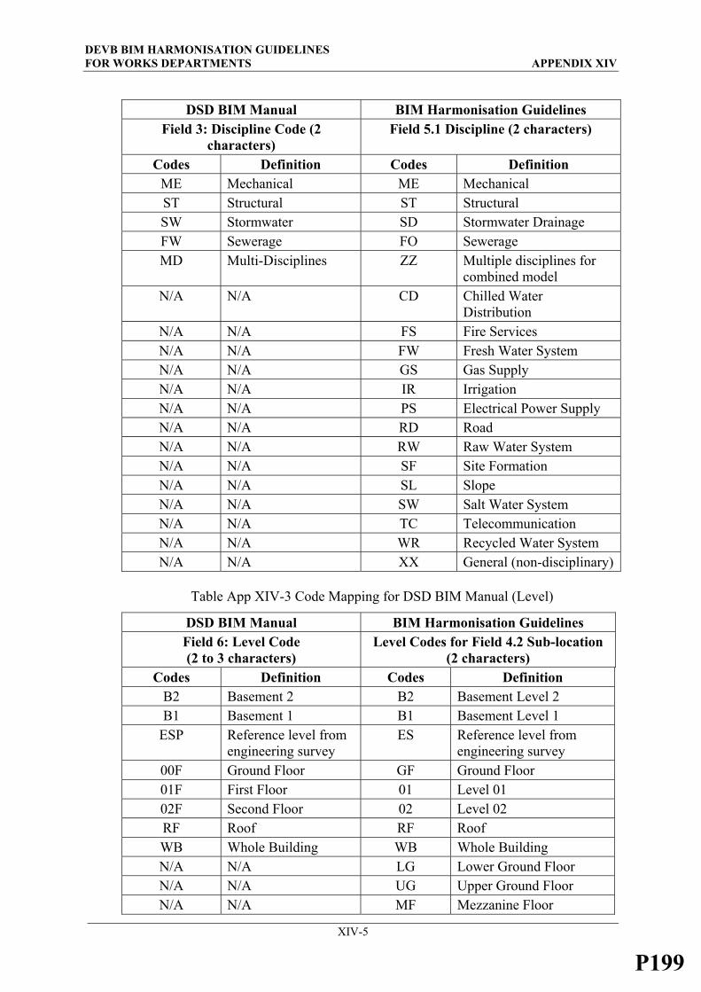
DEVB BIM HARMONISATION GUIDELINES FOR WORKS DEPARTMENTS APPENDIX XIV
XIV-5
DSD BIM Manual BIM Harmonisation Guidelines Field 3: Discipline Code (2
characters) Field 5.1 Discipline (2 characters)
Codes Definition Codes Definition ME Mechanical ME Mechanical ST Structural ST Structural SW Stormwater SD Stormwater Drainage FW Sewerage FO Sewerage MD Multi-Disciplines ZZ Multiple disciplines for
combined model N/A N/A CD Chilled Water
Distribution N/A N/A FS Fire Services N/A N/A FW Fresh Water System N/A N/A GS Gas Supply N/A N/A IR Irrigation N/A N/A PS Electrical Power Supply N/A N/A RD Road N/A N/A RW Raw Water System N/A N/A SF Site Formation N/A N/A SL Slope N/A N/A SW Salt Water System N/A N/A TC Telecommunication N/A N/A WR Recycled Water System N/A N/A XX General (non-disciplinary)
Table App XIV-3 Code Mapping for DSD BIM Manual (Level)
DSD BIM Manual BIM Harmonisation Guidelines Field 6: Level Code (2 to 3 characters)
Level Codes for Field 4.2 Sub-location (2 characters)
Codes Definition Codes Definition B2 Basement 2 B2 Basement Level 2 B1 Basement 1 B1 Basement Level 1
ESP Reference level from engineering survey
ES Reference level from engineering survey
00F Ground Floor GF Ground Floor 01F First Floor 01 Level 01 02F Second Floor 02 Level 02 RF Roof RF Roof WB Whole Building WB Whole Building N/A N/A LG Lower Ground Floor N/A N/A UG Upper Ground Floor N/A N/A MF Mezzanine Floor
P199
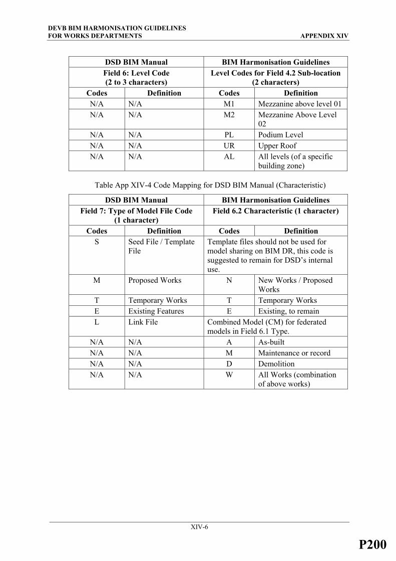
DEVB BIM HARMONISATION GUIDELINES FOR WORKS DEPARTMENTS APPENDIX XIV
XIV-6
DSD BIM Manual BIM Harmonisation Guidelines Field 6: Level Code (2 to 3 characters)
Level Codes for Field 4.2 Sub-location (2 characters)
Codes Definition Codes Definition N/A N/A M1 Mezzanine above level 01 N/A N/A M2 Mezzanine Above Level
02 N/A N/A PL Podium Level N/A N/A UR Upper Roof N/A N/A AL All levels (of a specific
building zone)
Table App XIV-4 Code Mapping for DSD BIM Manual (Characteristic)
DSD BIM Manual BIM Harmonisation Guidelines Field 7: Type of Model File Code
(1 character) Field 6.2 Characteristic (1 character)
Codes Definition Codes Definition S Seed File / Template
File Template files should not be used for model sharing on BIM DR, this code is suggested to remain for DSD’s internal use.
M Proposed Works N New Works / Proposed Works
T Temporary Works T Temporary Works E Existing Features E Existing, to remain L Link File Combined Model (CM) for federated
models in Field 6.1 Type. N/A N/A A As-built N/A N/A M Maintenance or record N/A N/A D Demolition N/A N/A W All Works (combination
of above works)
P200

DEVB BIM HARMONISATION GUIDELINES FOR WORKS DEPARTMENTS APPENDIX XV
– Mapping Table for Information Container ID Fields –
EMSD
P201
DEVB BIM HARMONISATION GUIDELINES FOR WORKS DEPARTMENTS APPENDIX XV
TABLE OF CONTENTS 1. EMSD .............................................................................................................................................. XV-1 1.1. Fields Mapping Table ...................................................................................................................... XV-1 1.2. Fields Mapping Diagram ................................................................................................................. XV-3 1.3. Fields that Matches with This Guide ............................................................................................... XV-4 1.4. Fields that Needs to be Mapped ...................................................................................................... XV-4
List of Tables
Table App XV-1 Field Mapping for EMSD BIM Guidelines ......................................................................... XV-1
Table App XV-2 Code Mapping for EMSD BIM Guidelines (Sub-location) ................................................. XV-4
Table App XV-3 Code Mapping for EMSD BIM Guidelines (Discipline) ..................................................... XV-5
Table App XV-4 Code Mapping for EMSD BIM Guidelines (Sub-discipline) .............................................. XV-6
List of Figures
Figure App XV-1 Field Mapping Diagram for EMSD BIM Guidelines ......................................................... XV-3
P202
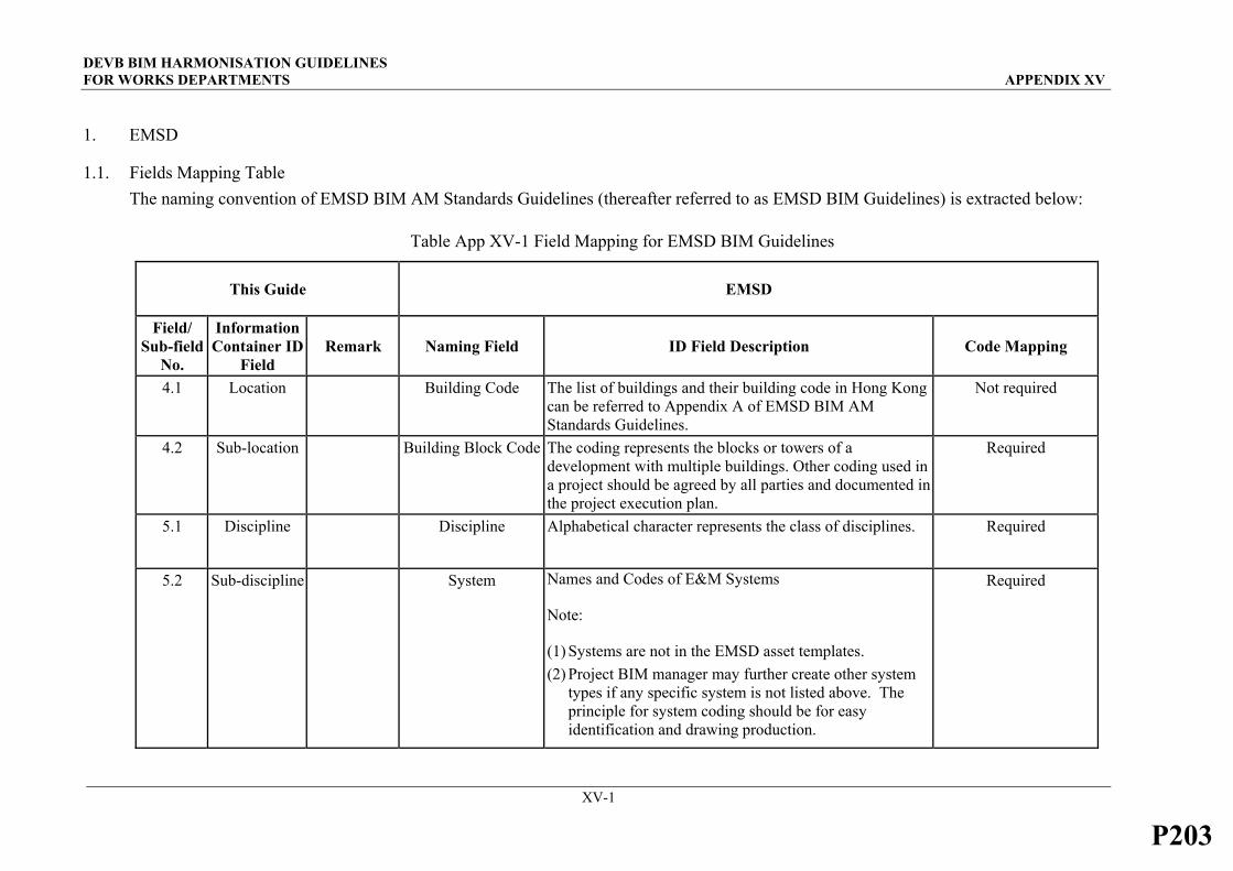
DEVB BIM HARMONISATION GUIDELINES FOR WORKS DEPARTMENTS APPENDIX XV
XV-1
1. EMSD
1.1. Fields Mapping Table The naming convention of EMSD BIM AM Standards Guidelines (thereafter referred to as EMSD BIM Guidelines) is extracted below:
Table App XV-1 Field Mapping for EMSD BIM Guidelines
This Guide EMSD
Field/ Sub-field
No.
Information Container ID
Field Remark Naming Field ID Field Description Code Mapping
4.1 Location Building Code The list of buildings and their building code in Hong Kong can be referred to Appendix A of EMSD BIM AM Standards Guidelines.
Not required
4.2 Sub-location Building Block Code The coding represents the blocks or towers of a development with multiple buildings. Other coding used in a project should be agreed by all parties and documented in the project execution plan.
Required
5.1 Discipline Discipline Alphabetical character represents the class of disciplines. Required
5.2 Sub-discipline System Names and Codes of E&M Systems
Note:
(1) Systems are not in the EMSD asset templates. (2) Project BIM manager may further create other system
types if any specific system is not listed above. The principle for system coding should be for easy identification and drawing production.
Required
P203
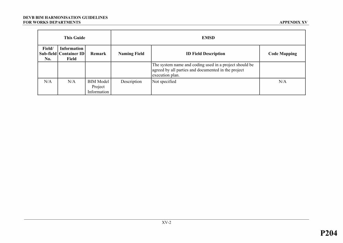
DEVB BIM HARMONISATION GUIDELINES FOR WORKS DEPARTMENTS APPENDIX XV
XV-2
This Guide EMSD
Field/ Sub-field
No.
Information Container ID
Field Remark Naming Field ID Field Description Code Mapping
The system name and coding used in a project should be agreed by all parties and documented in the project execution plan.
N/A N/A BIM Model Project
Information
Description Not specified N/A
P204
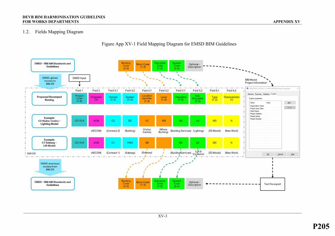
DEVB BIM HARMONISATION GUIDELINES FOR WORKS DEPARTMENTS APPENDIX XV
XV-3
1.2. Fields Mapping Diagram
Figure App XV-1 Field Mapping Diagram for EMSD BIM Guidelines
P205
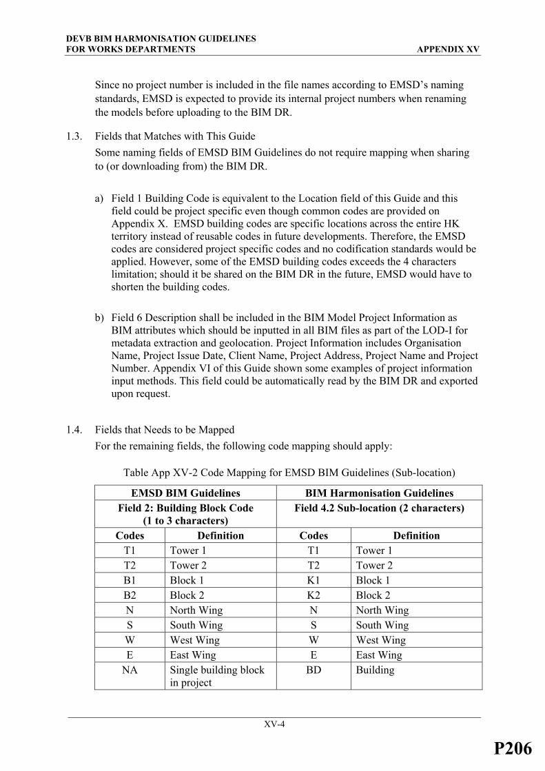
DEVB BIM HARMONISATION GUIDELINES FOR WORKS DEPARTMENTS APPENDIX XV
XV-4
Since no project number is included in the file names according to EMSD’s naming standards, EMSD is expected to provide its internal project numbers when renaming the models before uploading to the BIM DR.
1.3. Fields that Matches with This Guide Some naming fields of EMSD BIM Guidelines do not require mapping when sharing to (or downloading from) the BIM DR.
a) Field 1 Building Code is equivalent to the Location field of this Guide and this field could be project specific even though common codes are provided on Appendix X. EMSD building codes are specific locations across the entire HK territory instead of reusable codes in future developments. Therefore, the EMSD codes are considered project specific codes and no codification standards would be applied. However, some of the EMSD building codes exceeds the 4 characters limitation; should it be shared on the BIM DR in the future, EMSD would have to shorten the building codes.
b) Field 6 Description shall be included in the BIM Model Project Information as BIM attributes which should be inputted in all BIM files as part of the LOD-I for metadata extraction and geolocation. Project Information includes Organisation Name, Project Issue Date, Client Name, Project Address, Project Name and Project Number. Appendix VI of this Guide shown some examples of project information input methods. This field could be automatically read by the BIM DR and exported upon request.
1.4. Fields that Needs to be Mapped For the remaining fields, the following code mapping should apply:
Table App XV-2 Code Mapping for EMSD BIM Guidelines (Sub-location)
EMSD BIM Guidelines BIM Harmonisation Guidelines Field 2: Building Block Code
(1 to 3 characters) Field 4.2 Sub-location (2 characters)
Codes Definition Codes Definition T1 Tower 1 T1 Tower 1 T2 Tower 2 T2 Tower 2 B1 Block 1 K1 Block 1 B2 Block 2 K2 Block 2 N North Wing N North Wing S South Wing S South Wing W West Wing W West Wing E East Wing E East Wing
NA Single building block in project
BD Building
P206
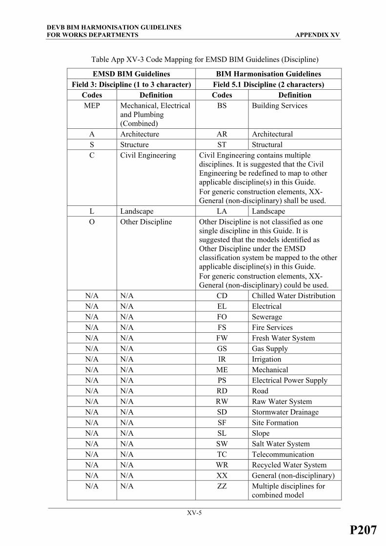
DEVB BIM HARMONISATION GUIDELINES FOR WORKS DEPARTMENTS APPENDIX XV
XV-5
Table App XV-3 Code Mapping for EMSD BIM Guidelines (Discipline)
EMSD BIM Guidelines BIM Harmonisation Guidelines Field 3: Discipline (1 to 3 character) Field 5.1 Discipline (2 characters)
Codes Definition Codes Definition MEP Mechanical, Electrical
and Plumbing (Combined)
BS Building Services
A Architecture AR Architectural S Structure ST Structural C Civil Engineering Civil Engineering contains multiple
disciplines. It is suggested that the Civil Engineering be redefined to map to other applicable discipline(s) in this Guide. For generic construction elements, XX- General (non-disciplinary) shall be used.
L Landscape LA Landscape O Other Discipline Other Discipline is not classified as one
single discipline in this Guide. It is suggested that the models identified as Other Discipline under the EMSD classification system be mapped to the other applicable discipline(s) in this Guide. For generic construction elements, XX- General (non-disciplinary) could be used.
N/A N/A CD Chilled Water Distribution N/A N/A EL Electrical N/A N/A FO Sewerage N/A N/A FS Fire Services N/A N/A FW Fresh Water System N/A N/A GS Gas Supply N/A N/A IR Irrigation N/A N/A ME Mechanical N/A N/A PS Electrical Power Supply N/A N/A RD Road N/A N/A RW Raw Water System N/A N/A SD Stormwater Drainage N/A N/A SF Site Formation N/A N/A SL Slope N/A N/A SW Salt Water System N/A N/A TC Telecommunication N/A N/A WR Recycled Water System N/A N/A XX General (non-disciplinary) N/A N/A ZZ Multiple disciplines for
combined model
P207
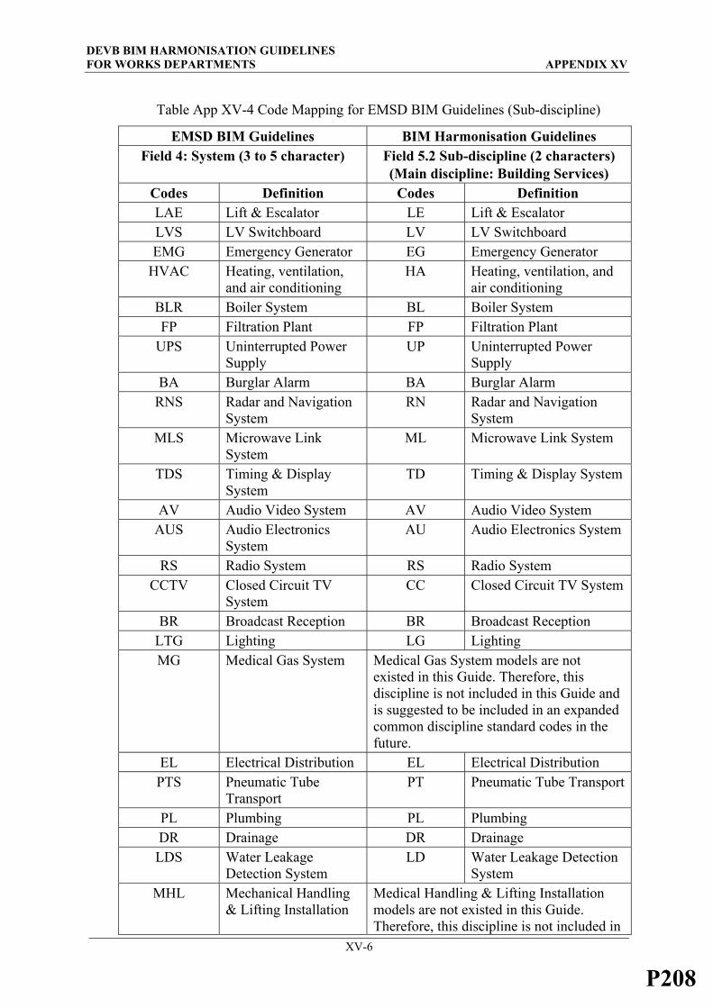
DEVB BIM HARMONISATION GUIDELINES FOR WORKS DEPARTMENTS APPENDIX XV
XV-6
Table App XV-4 Code Mapping for EMSD BIM Guidelines (Sub-discipline)
EMSD BIM Guidelines BIM Harmonisation Guidelines Field 4: System (3 to 5 character) Field 5.2 Sub-discipline (2 characters)
(Main discipline: Building Services) Codes Definition Codes Definition LAE Lift & Escalator LE Lift & Escalator LVS LV Switchboard LV LV Switchboard EMG Emergency Generator EG Emergency Generator
HVAC Heating, ventilation, and air conditioning
HA Heating, ventilation, and air conditioning
BLR Boiler System BL Boiler System FP Filtration Plant FP Filtration Plant
UPS Uninterrupted Power Supply
UP Uninterrupted Power Supply
BA Burglar Alarm BA Burglar Alarm RNS Radar and Navigation
System RN Radar and Navigation
System MLS Microwave Link
System ML Microwave Link System
TDS Timing & Display System
TD Timing & Display System
AV Audio Video System AV Audio Video System AUS Audio Electronics
System AU Audio Electronics System
RS Radio System RS Radio System CCTV Closed Circuit TV
System CC Closed Circuit TV System
BR Broadcast Reception BR Broadcast Reception LTG Lighting LG Lighting MG Medical Gas System Medical Gas System models are not
existed in this Guide. Therefore, this discipline is not included in this Guide and is suggested to be included in an expanded common discipline standard codes in the future.
EL Electrical Distribution EL Electrical Distribution PTS Pneumatic Tube
Transport PT Pneumatic Tube Transport
PL Plumbing PL Plumbing DR Drainage DR Drainage LDS Water Leakage
Detection System LD Water Leakage Detection
System MHL Mechanical Handling
& Lifting Installation Medical Handling & Lifting Installation models are not existed in this Guide. Therefore, this discipline is not included in
P208
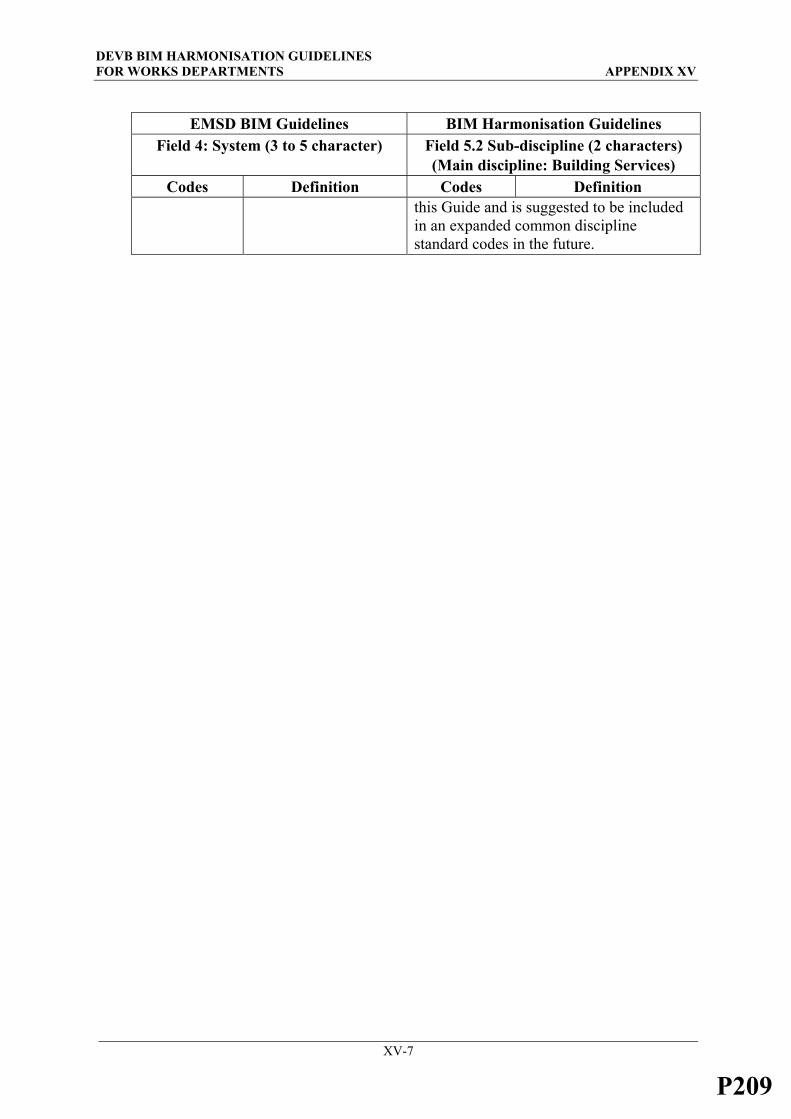
DEVB BIM HARMONISATION GUIDELINES FOR WORKS DEPARTMENTS APPENDIX XV
XV-7
EMSD BIM Guidelines BIM Harmonisation Guidelines Field 4: System (3 to 5 character) Field 5.2 Sub-discipline (2 characters)
(Main discipline: Building Services) Codes Definition Codes Definition
this Guide and is suggested to be included in an expanded common discipline standard codes in the future.
P209
DEVB BIM HARMONISATION GUIDELINES FOR WORKS DEPARTMENTS APPENDIX XVI
– Mapping Table for Information Container ID Fields –
HyD
P210
DEVB BIM HARMONISATION GUIDELINES FOR WORKS DEPARTMENTS APPENDIX XVI
TABLE OF CONTENTS 1. HyD ................................................................................................................................................ XVI-1 1.1. Fields Mapping Table ..................................................................................................................... XVI-1 1.2. Fields Mapping Diagram ................................................................................................................ XVI-4 1.3. Fields that Matches with this Guide ............................................................................................... XVI-5 1.4. Fields that Needs to be Mapped ..................................................................................................... XVI-5
List of Tables
Table App XVI-1 Field Mapping of HyD BIM Guidelines ............................................................................ XVI-1
Table App XVI-2 Code Mapping for HyD BIM Guidelines .......................................................................... XVI-5
List of Figures
Figure App XVI-1 Mapping Diagram for HyD BIM Guidelines ................................................................... XVI-4
P211
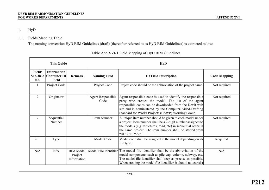
DEVB BIM HARMONISATION GUIDELINES FOR WORKS DEPARTMENTS APPENDIX XVI
XVI-1
1. HyD
1.1. Fields Mapping Table The naming convention HyD BIM Guidelines (draft) (thereafter referred to as HyD BIM Guidelines) is extracted below:
Table App XVI-1 Field Mapping of HyD BIM Guidelines
This Guide HyD
Field/ Sub-field
No.
Information Container ID
Field Remark Naming Field ID Field Description Code Mapping
1 Project Code Project Code Project code should be the abbreviation of the project name. Not required
2 Originator Agent Responsible Code
Agent responsible code is used to identify the responsible party who creates the model. The list of the agent responsible codes can be downloaded from the DevB web site and is administered by the Computer-Aided-Drafting Standard for Works Projects (CSWP) Working Group.
Not required
7 Sequential Number
Item Number A unique item number should be given to each model under a project. Item number shall be a 2-digit number assigned to the models (e.g. structures, road, etc) in sequential order in the same project. The item number shall be started from “01” until “99”.
Not required
6.1 Type Model Code Model code shall be assigned to the model depending on its file type.
Required
N/A N/A BIM Model Project
Information
Model File Identifier The model file identifier shall be the abbreviation of the model components such as pile cap, column, subway, etc. The model file identifier shall keep as precise as possible. When creating the model file identifier, it should not consist
N/A
P212
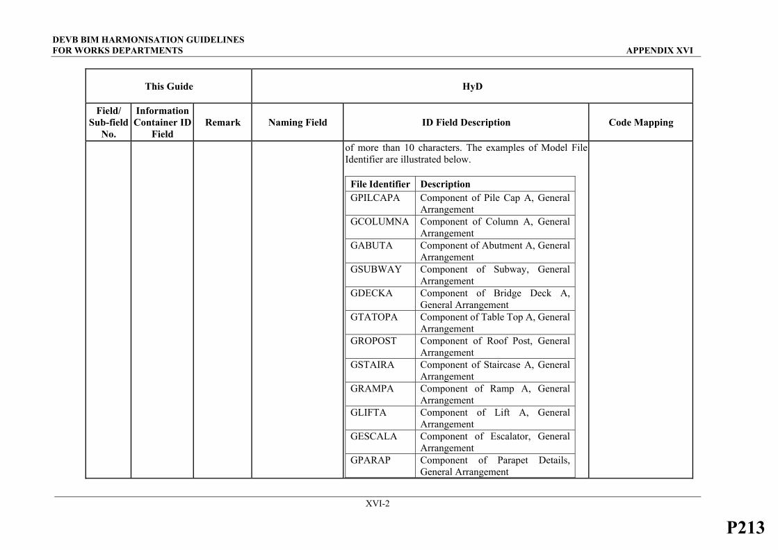
DEVB BIM HARMONISATION GUIDELINES FOR WORKS DEPARTMENTS APPENDIX XVI
XVI-2
This Guide HyD
Field/ Sub-field
No.
Information Container ID
Field Remark Naming Field ID Field Description Code Mapping
of more than 10 characters. The examples of Model File Identifier are illustrated below.
File Identifier Description GPILCAPA Component of Pile Cap A, General
Arrangement GCOLUMNA Component of Column A, General
Arrangement GABUTA Component of Abutment A, General
Arrangement GSUBWAY Component of Subway, General
Arrangement GDECKA Component of Bridge Deck A,
General Arrangement GTATOPA Component of Table Top A, General
Arrangement GROPOST Component of Roof Post, General
Arrangement GSTAIRA Component of Staircase A, General
Arrangement GRAMPA Component of Ramp A, General
Arrangement GLIFTA Component of Lift A, General
Arrangement GESCALA Component of Escalator, General
Arrangement GPARAP Component of Parapet Details,
General Arrangement
P213
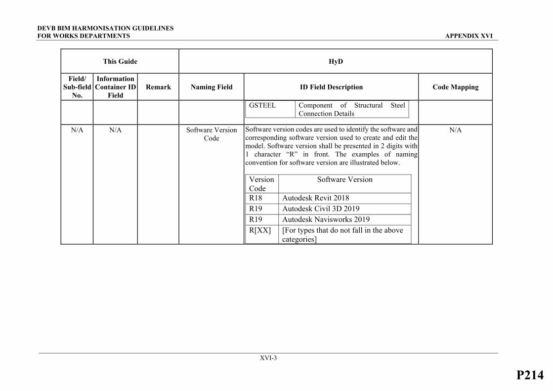
DEVB BIM HARMONISATION GUIDELINES FOR WORKS DEPARTMENTS APPENDIX XVI
XVI-3
This Guide HyD
Field/ Sub-field
No.
Information Container ID
Field Remark Naming Field ID Field Description Code Mapping
GSTEEL Component of Structural Steel Connection Details
N/A N/A
Software Version Code
Software version codes are used to identify the software and corresponding software version used to create and edit the model. Software version shall be presented in 2 digits with 1 character “R” in front. The examples of naming convention for software version are illustrated below.
Version Code
Software Version
R18 Autodesk Revit 2018 R19 Autodesk Civil 3D 2019 R19 Autodesk Navisworks 2019 R[XX] [For types that do not fall in the above
categories]
N/A
P214
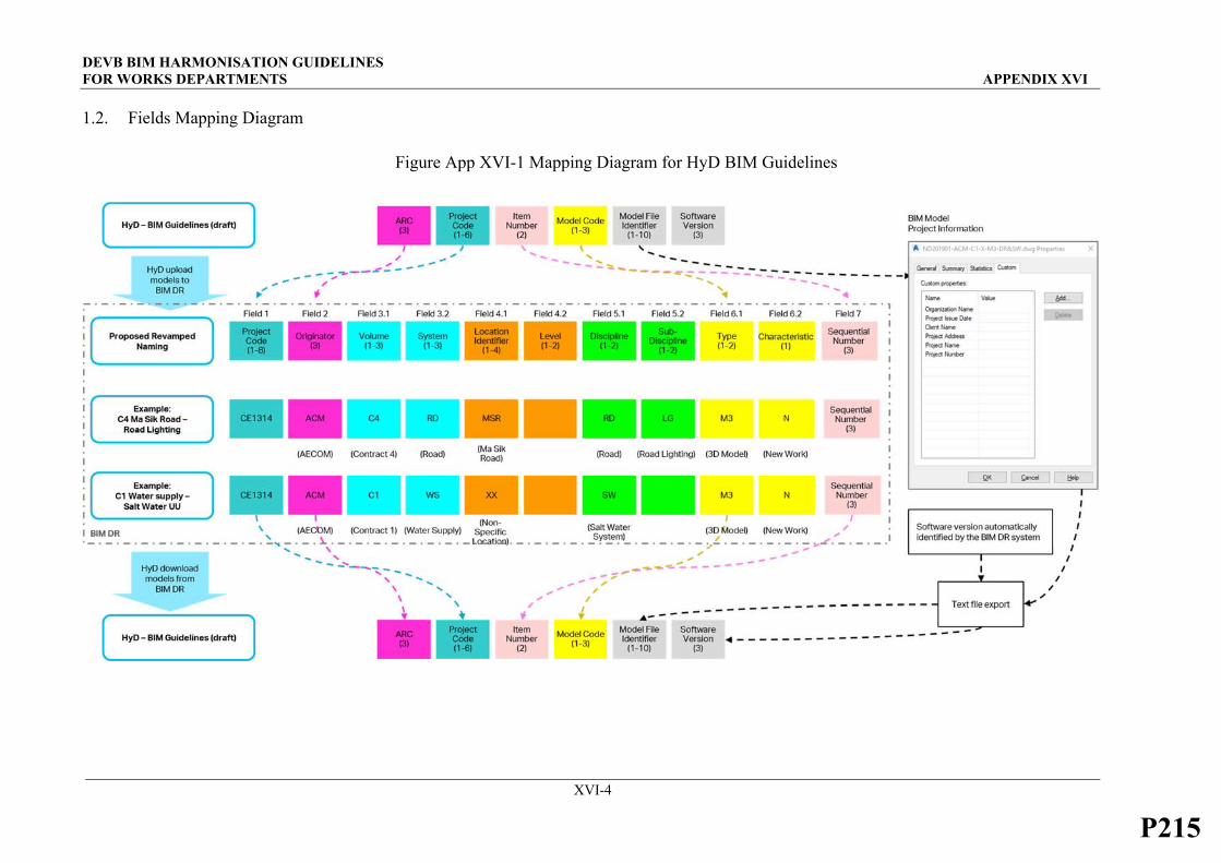
DEVB BIM HARMONISATION GUIDELINES FOR WORKS DEPARTMENTS APPENDIX XVI
XVI-4
1.2. Fields Mapping Diagram
Figure App XVI-1 Mapping Diagram for HyD BIM Guidelines
P215
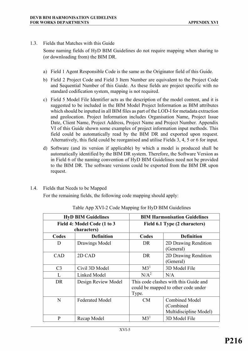
DEVB BIM HARMONISATION GUIDELINES FOR WORKS DEPARTMENTS APPENDIX XVI
XVI-5
1.3. Fields that Matches with this Guide Some naming fields of HyD BIM Guidelines do not require mapping when sharing to (or downloading from) the BIM DR.
a) Field 1 Agent Responsible Code is the same as the Originator field of this Guide. b) Field 2 Project Code and Field 3 Item Number are equivalent to the Project Code
and Sequential Number of this Guide. As these fields are project specific with no standard codification system, mapping is not required.
c) Field 5 Model File Identifier acts as the description of the model content, and it is suggested to be included in the BIM Model Project Information as BIM attributes which should be inputted in all BIM files as part of the LOD-I for metadata extraction and geolocation. Project Information includes Organisation Name, Project Issue Date, Client Name, Project Address, Project Name and Project Number. Appendix VI of this Guide shown some examples of project information input methods. This field could be automatically read by the BIM DR and exported upon request. Alternatively, this field could be reorganised and utilise Fields 3, 4, 5 or 6 for input.
d) Software (and its version if applicable) by which a model is produced shall be automatically identified by the BIM DR system. Therefore, the Software Version as in Field 6 of the naming convention of HyD BIM Guidelines need not be provided to the BIM DR. The software versions could be exported from the BIM DR upon request.
1.4. Fields that Needs to be Mapped For the remaining fields, the following code mapping should apply:
Table App XVI-2 Code Mapping for HyD BIM Guidelines
HyD BIM Guidelines BIM Harmonisation Guidelines Field 4: Model Code (1 to 3
characters) Field 6.1 Type (2 characters)
Codes Definition Codes Definition D Drawings Model DR 2D Drawing Rendition
(General) CAD 2D CAD DR 2D Drawing Rendition
(General) C3 Civil 3D Model M31 3D Model File L Linked Model N/A2 N/A
DR Design Review Model This code clashes with this Guide and could be mapped to other code under Type.
N Federated Model CM Combined Model (Combined Multidiscipline Model)
P Recap Model M31 3D Model File
P216
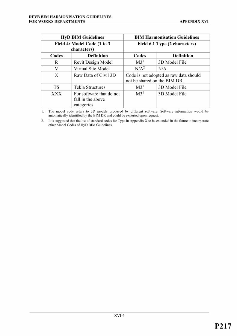
DEVB BIM HARMONISATION GUIDELINES FOR WORKS DEPARTMENTS APPENDIX XVI
XVI-6
HyD BIM Guidelines BIM Harmonisation Guidelines Field 4: Model Code (1 to 3
characters) Field 6.1 Type (2 characters)
Codes Definition Codes Definition R Revit Design Model M31 3D Model File V Virtual Site Model N/A2 N/A X Raw Data of Civil 3D Code is not adopted as raw data should
not be shared on the BIM DR. TS Tekla Structures M31 3D Model File
XXX For software that do not fall in the above categories
M31 3D Model File
1. The model code refers to 3D models produced by different software. Software information would be automatically identified by the BIM DR and could be exported upon request.
2. It is suggested that the list of standard codes for Type in Appendix X to be extended in the future to incorporate other Model Codes of HyD BIM Guidelines.
P217
DEVB BIM HARMONISATION GUIDELINES FOR WORKS DEPARTMENTS APPENDIX XVII
– Mapping Table for Information Container ID Fields –
WSD
P218

DEVB BIM HARMONISATION GUIDELINES FOR WORKS DEPARTMENTS APPENDIX XVII
TABLE OF CONTENTS 1. WSD .............................................................................................................................................. XVII-1 1.1. Fields Mapping .............................................................................................................................. XVII-1 1.2. Fields Mapping Diagram ............................................................................................................... XVII-3 1.3. Fields that Matches with this Guide .............................................................................................. XVII-4 1.4. Fields That Needs to be Mapped ................................................................................................... XVII-4
List of Tables
Table App XVII-1 Field Mapping for WSD BIM Manual .......................................................................... XVII-1
Table App XVII-2 Code Mapping for WSD BIM Manual .......................................................................... XVII-4
List of Figures
Figure App XVII-1 Field Mapping Diagram for WSD BIM Manual .......................................................... XVII-3
P219
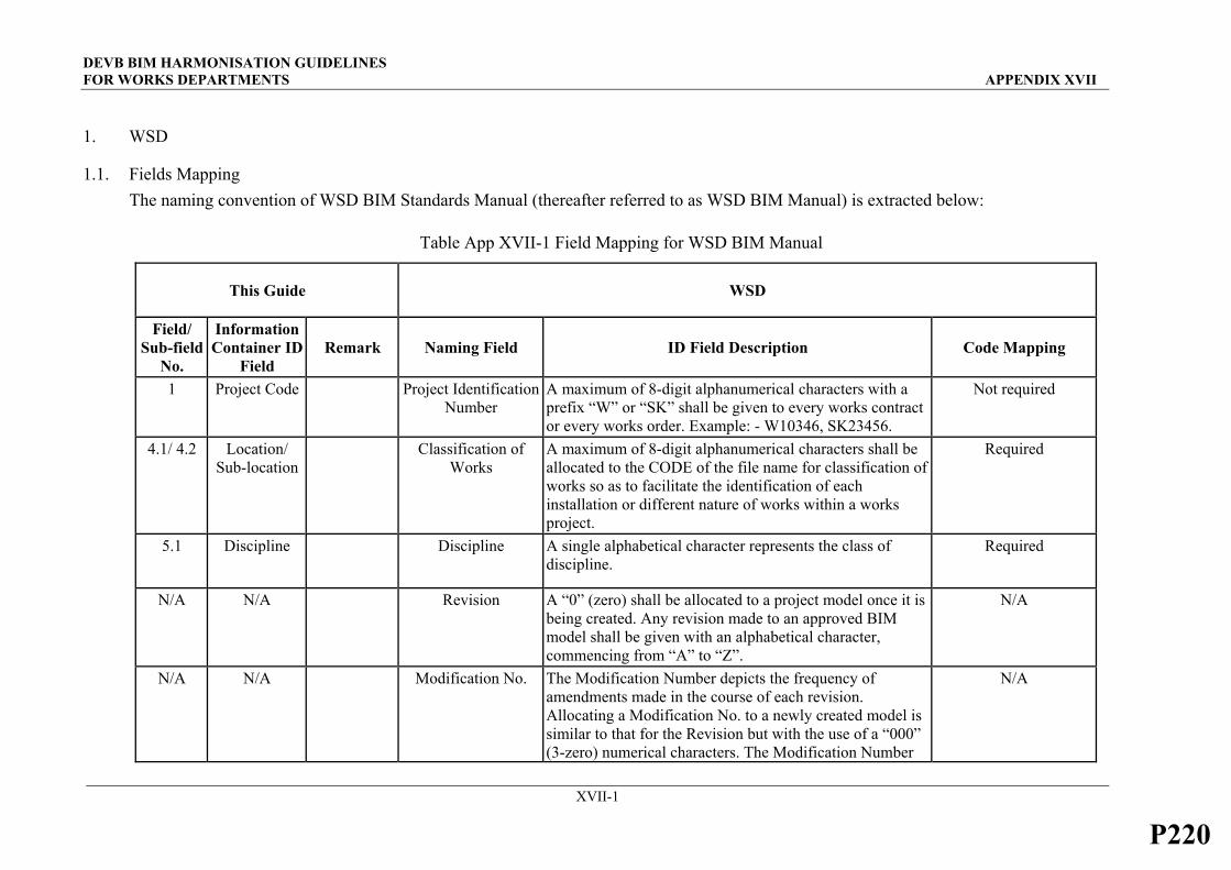
DEVB BIM HARMONISATION GUIDELINES FOR WORKS DEPARTMENTS APPENDIX XVII
XVII-1
1. WSD
1.1. Fields Mapping The naming convention of WSD BIM Standards Manual (thereafter referred to as WSD BIM Manual) is extracted below:
Table App XVII-1 Field Mapping for WSD BIM Manual
This Guide WSD
Field/ Sub-field
No.
Information Container ID
Field Remark Naming Field ID Field Description Code Mapping
1 Project Code Project Identification Number
A maximum of 8-digit alphanumerical characters with a prefix “W” or “SK” shall be given to every works contract or every works order. Example: - W10346, SK23456.
Not required
4.1/ 4.2 Location/ Sub-location
Classification of Works
A maximum of 8-digit alphanumerical characters shall be allocated to the CODE of the file name for classification of works so as to facilitate the identification of each installation or different nature of works within a works project.
Required
5.1 Discipline Discipline A single alphabetical character represents the class of discipline.
Required
N/A N/A Revision A “0” (zero) shall be allocated to a project model once it is being created. Any revision made to an approved BIM model shall be given with an alphabetical character, commencing from “A” to “Z”.
N/A
N/A N/A Modification No. The Modification Number depicts the frequency of amendments made in the course of each revision. Allocating a Modification No. to a newly created model is similar to that for the Revision but with the use of a “000” (3-zero) numerical characters. The Modification Number
N/A
P220
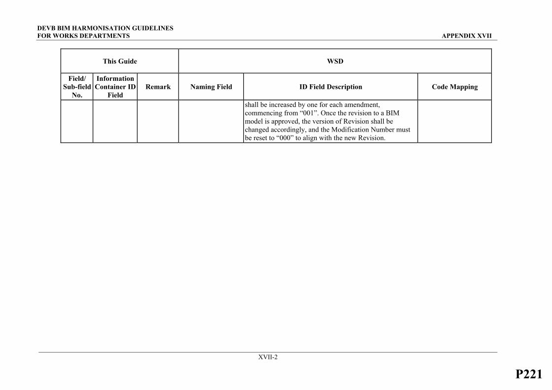
DEVB BIM HARMONISATION GUIDELINES FOR WORKS DEPARTMENTS APPENDIX XVII
XVII-2
This Guide WSD
Field/ Sub-field
No.
Information Container ID
Field Remark Naming Field ID Field Description Code Mapping
shall be increased by one for each amendment, commencing from “001”. Once the revision to a BIM model is approved, the version of Revision shall be changed accordingly, and the Modification Number must be reset to “000” to align with the new Revision.
P221
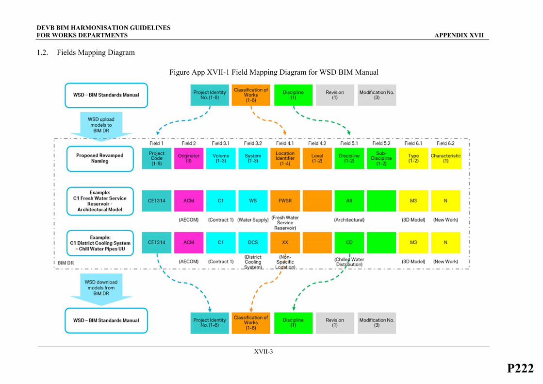
DEVB BIM HARMONISATION GUIDELINES FOR WORKS DEPARTMENTS APPENDIX XVII
XVII-3
1.2. Fields Mapping Diagram
Figure App XVII-1 Field Mapping Diagram for WSD BIM Manual
P222
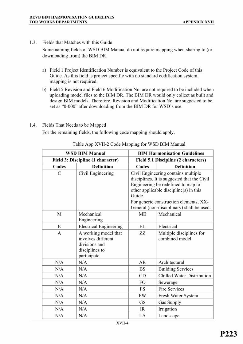
DEVB BIM HARMONISATION GUIDELINES FOR WORKS DEPARTMENTS APPENDIX XVII
XVII-4
1.3. Fields that Matches with this Guide Some naming fields of WSD BIM Manual do not require mapping when sharing to (or downloading from) the BIM DR.
a) Field 1 Project Identification Number is equivalent to the Project Code of this Guide. As this field is project specific with no standard codification system, mapping is not required.
b) Field 5 Revision and Field 6 Modification No. are not required to be included when uploading model files to the BIM DR. The BIM DR would only collect as built and design BIM models. Therefore, Revision and Modification No. are suggested to be set as “0-000” after downloading from the BIM DR for WSD’s use.
1.4. Fields That Needs to be Mapped For the remaining fields, the following code mapping should apply.
Table App XVII-2 Code Mapping for WSD BIM Manual
WSD BIM Manual BIM Harmonisation Guidelines Field 3: Discipline (1 character) Field 5.1 Discipline (2 characters) Codes Definition Codes Definition
C Civil Engineering Civil Engineering contains multiple disciplines. It is suggested that the Civil Engineering be redefined to map to other applicable discipline(s) in this Guide. For generic construction elements, XX- General (non-disciplinary) shall be used.
M Mechanical Engineering
ME Mechanical
E Electrical Engineering EL Electrical A A working model that
involves different divisions and disciplines to participate
ZZ Multiple disciplines for combined model
N/A N/A AR Architectural N/A N/A BS Building Services N/A N/A CD Chilled Water Distribution N/A N/A FO Sewerage N/A N/A FS Fire Services N/A N/A FW Fresh Water System N/A N/A GS Gas Supply N/A N/A IR Irrigation N/A N/A LA Landscape
P223
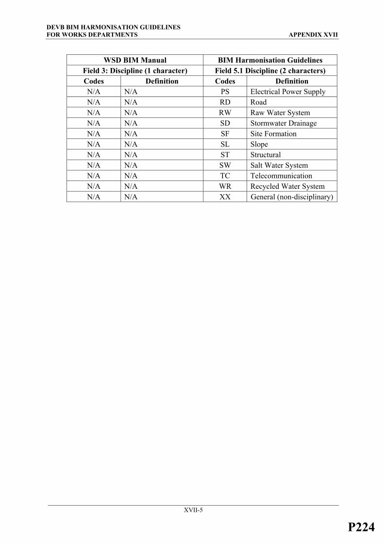
DEVB BIM HARMONISATION GUIDELINES FOR WORKS DEPARTMENTS APPENDIX XVII
XVII-5
WSD BIM Manual BIM Harmonisation Guidelines Field 3: Discipline (1 character) Field 5.1 Discipline (2 characters) Codes Definition Codes Definition N/A N/A PS Electrical Power Supply N/A N/A RD Road N/A N/A RW Raw Water System N/A N/A SD Stormwater Drainage N/A N/A SF Site Formation N/A N/A SL Slope N/A N/A ST Structural N/A N/A SW Salt Water System N/A N/A TC Telecommunication N/A N/A WR Recycled Water System N/A N/A XX General (non-disciplinary)
P224
DEVB BIM HARMONISATION GUIDELINES FOR WORKS DEPARTMENTS APPENDIX XVIII
– Sample Project Close-out Checklist
P225
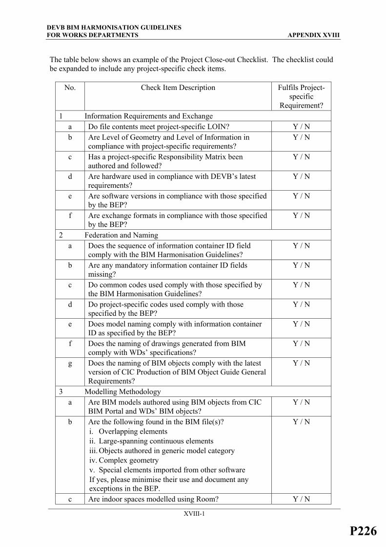
DEVB BIM HARMONISATION GUIDELINES FOR WORKS DEPARTMENTS APPENDIX XVIII
XVIII-1
The table below shows an example of the Project Close-out Checklist. The checklist could be expanded to include any project-specific check items.
No. Check Item Description Fulfils Project-
specific Requirement?
1 Information Requirements and Exchange a Do file contents meet project-specific LOIN? Y / N b Are Level of Geometry and Level of Information in
compliance with project-specific requirements? Y / N
c Has a project-specific Responsibility Matrix been authored and followed?
Y / N
d Are hardware used in compliance with DEVB’s latest requirements?
Y / N
e Are software versions in compliance with those specified by the BEP?
Y / N
f Are exchange formats in compliance with those specified by the BEP?
Y / N
2 Federation and Naming a Does the sequence of information container ID field
comply with the BIM Harmonisation Guidelines? Y / N
b Are any mandatory information container ID fields missing?
Y / N
c Do common codes used comply with those specified by the BIM Harmonisation Guidelines?
Y / N
d Do project-specific codes used comply with those specified by the BEP?
Y / N
e Does model naming comply with information container ID as specified by the BEP?
Y / N
f Does the naming of drawings generated from BIM comply with WDs’ specifications?
Y / N
g Does the naming of BIM objects comply with the latest version of CIC Production of BIM Object Guide General Requirements?
Y / N
3 Modelling Methodology a Are BIM models authored using BIM objects from CIC
BIM Portal and WDs’ BIM objects? Y / N
b Are the following found in the BIM file(s)? i. Overlapping elements ii. Large-spanning continuous elements iii. Objects authored in generic model category iv. Complex geometry v. Special elements imported from other software If yes, please minimise their use and document any exceptions in the BEP.
Y / N
c Are indoor spaces modelled using Room? Y / N
P226
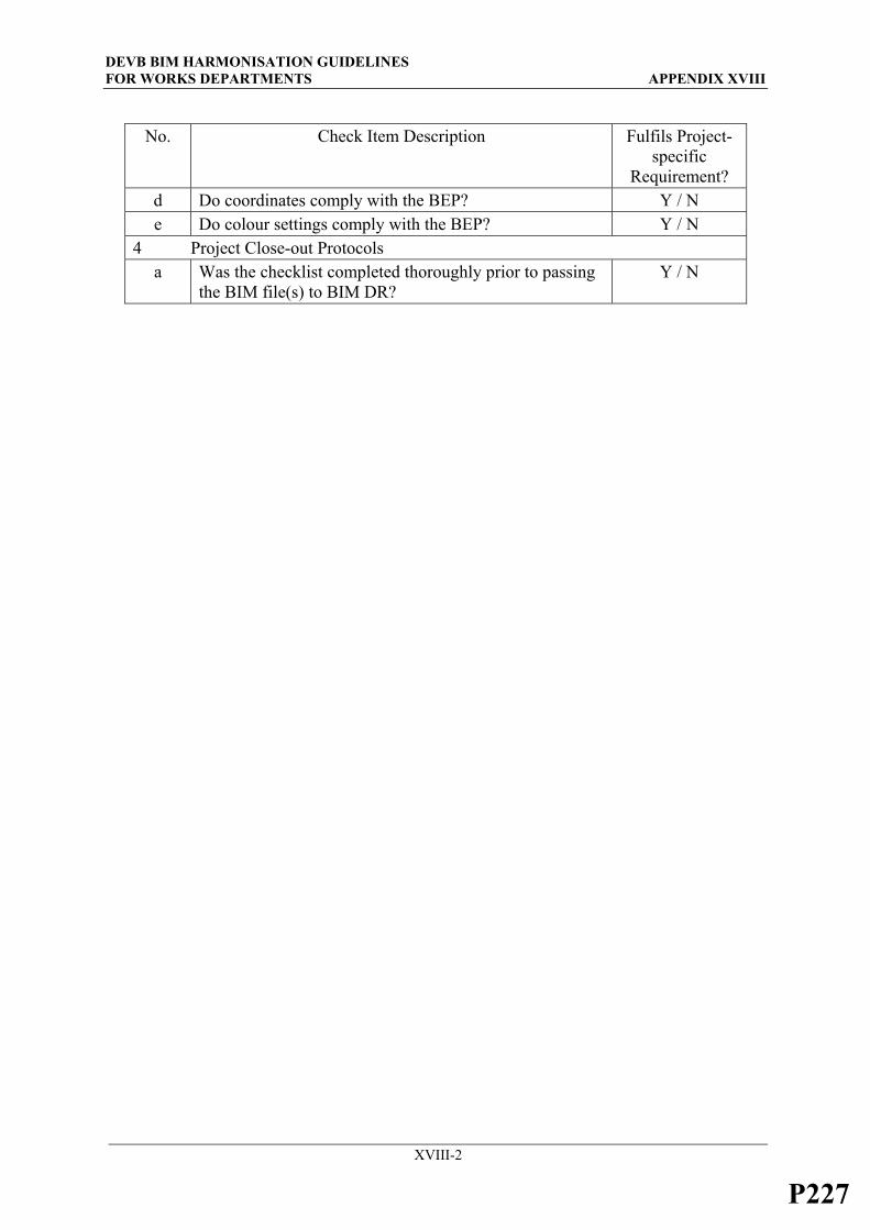
DEVB BIM HARMONISATION GUIDELINES FOR WORKS DEPARTMENTS APPENDIX XVIII
XVIII-2
No. Check Item Description Fulfils Project-specific
Requirement? d Do coordinates comply with the BEP? Y / N e Do colour settings comply with the BEP? Y / N
4 Project Close-out Protocols a Was the checklist completed thoroughly prior to passing
the BIM file(s) to BIM DR? Y / N
P227