design of flexible pavement
TRANSCRIPT
DESIGN OF FLEXIBLE PAVEMENT
CONTENTS
S. NO. Topic Page No.
1. INTRODUCTION 2. REPORT3. GEOMETRIC DESIGN OF HIGHWAY4. CURVES5. ROAD DRAINAGE6. HIGHWAY MAINTENANCE7. TRAFFIC ENGINEERING8. ATTERBERG LIMITS9. COMPACTION TEST10. C.B.R. TEST11. FLAKINESS & ELONGATION INDEX12. AGGREGATE IMPACT TEST13. ABRASION TEST14. FIELD BOOK15. CROSS SECTIONS OF THE ROAD16. LONGITUDINAL SECTION OF THE ROAD17. QUANTITY ESTIMATION18. DETAILED ESTIMATE
19. DATA SHEET20. ABSTRACT21. DIAGRAMS22. BIBLIOGRAPHY
INTRODUCTIONRoad is defined as a structure constructed on the surface of the earth to facilitate the easy movement from men & materials i.e., Traffic from one place to another. Traffic includes carts, cycles, motors & pedestrians
Road is means of transportation that contributes to the economy and industrial development of country. Roads promote ration’s wealth by keeping its people and goods moving. Road transportation plays some important role in maintaining better law and order and in advancement of country and community. It also serves at the time of emergency for defense in making strategic movements.
IMPORTANCE OF ROAD TRANSPORTATION
The history of road is as old as the history of man on the earth. First of all, the man makes footpath for hunting for food as the forest road. As science has developed, the special types of roads arepracticed.
ADVANTAGES OF ROADS:
At the time of wars roads plays an important role in the defenceof country.
They help in maintaining better law order in a country. They facilitate conveyance of people, goods, raw materials etc.,
speedily and easily in the different parts of a country. The act as the source of communication in regionsof high
altitudes i.e., maintains regions. They help in growth of trade and other economic activities in
and outside the villages and towns by establishing contact between towns and villages.
They help in providing efficient distribution of agricultural products and natural resources all over the country.
They help in price stabilization of commodities due to mobility of products all over the country.
They help in cultural and social advancement of people and making the villages active and alert members of the community.
They help in promoting the cultural and social ties among peopleliving in different parts of a country and thus strengthen the national unity.
They help in providing improved medical facilities quickly to human beings especially to those who live in rural areas.
They enhance land value and thus bring better revenue. They serve as feeders for airways, waterways and railways. They help in reducing distress among the peoples, caused due to
famine, by supplying them food and clothing quickly.Lastly, it can be said that road are the symbol of the countriesprogress.Moreover,this development made by and country can be judged by the quality and the network of system.
CLASSIFICATION OF ROADS:
I. According the administration, roads are classified intoo National high ways
o State high ways o District roadso Village roads
NATIONAL HIGH WAYS
The roads connecting state capitals, ports and foreign highways and roads of military importance, which are financed b central government, are known as National Highways.
STATE HIGHWAYS
The roads connecting important cities, state capitals, and district headquarters, national and state highways of neighboring states that are financed by state governments are known as “state highways”.
DISTRICT ROADSThey are again divided in to
Major District Roads: The roads are connecting centers of producing and marketing, district headquarters, taluk headquarters with state and National Highway are known as major district roads.
Other District Roads: The other roads of less important in the district are known as district roads.
VILLAGE ROADS:
The Roads connecting villages with each other, to district roads and which financed by panchayats are known as Village roads.
II ACCORDING TO MATERIALS USED FOR ROAD CONSTRUCTION, ROADS ARE CLASSIFIED INTO
Earth roads or stabilized soil roads. Gravel roads
Water bound macadam roads(WBM) Bituminous road or Black topped surface (B.T.Road). Cement concrete roads
ACCORDING TO LOCATING, ROADS ARE CLASSIFIEED INTO
Street Roads Rural Roads Urban Roads By-pass Roads Ghat Roads
STREET ROADS
The roads connecting the different places of built up areas are known as street roads.
RURAL ROADS
Roads constructed in outer open area in villages are called as rural roads.These roads do not have any Kerbs in foot-path. But they have shoulders and berms.
URBAN ROADS
Road constructed by the side of the congested are or other obstructions, are called by-pass roads. Through traffic avoids main roads leading to congested and difficult areas.
GHAT ROADS
The roads are constructed in hilly areas are termed as Ghat Roads or Hill Roads.
INTRODUCTION
The history of road is as old as the history of man on the earth. Thepre-historic man traced out a narrow-way for going out for hunting the food. This pathway is considered as the first road mark laid on the surface of earth. The utility and necessary of the pathway gradually developed with the introduction of two wheeled carts. The pathways were or widened into a roadway, which was the beginning of
road as a means of communication and transport.
During the Aryan period there are references in rig Veda about Mahapathas as a means of communication. And also the excavations as “Mohenjo-Daro” and “Harappa” have Established that even 3500 years B.C., Road construction was practiced around 500 years before the earliest recorded road construction was in Egypt. InEurope the oldest road was built in about 2000 B.C.
The royal root for processions was built in Babylon around 1620 B.C.,Another noteworthy road known as Persian royal road, a Trade-cum-military route was built for a length of 2400Km from Smyrnato the Perian-Gulf in the Persian Emprise which has the (520-485 B.C.) ruled by Darius-I.
Chandragupta Maurya (322-2989 B.C.,) took interest in the maintenance and development of roads.These Emperor Asoka took specialinterest in the improvement of roads and provided facilities to the travelers, such facilities were in the form of planting of trees, digging wells and constructing rest houses etc.
ROADS IN BRITISH PERIOD:
The first systematic road organization in the form of central and state PWP’s (Public Works Department) was formed during regime of Lord Dul Housie 1855.In the year 1919, because of growing importance of railways, roads became a provincial subject which resulted in a great setback to the road development in the year1927, the Indian roads and transport Development association (I.R.T.D.A) was setup with headquarters at Bombay and branch office at Delhi.
After World war-I motor transport came to the forefront, which created revolution in India’s Transportation system.
In 1927, the Central Government appointed the jayakar to report on the conditions of existing roads and to suggest ways and
means for their future development. IN 1928, the jayakar committee recommended that since, the provincial government and the local bodies were unable to look after all the important roads of national importance. On recommendations of the jayakar committee, the central road fund was enforced on first March, 1929.
In1934, a semi-official body known as Indian road Congress (IRC) was established by the Central Government as per the recommendations of the jayakar committee. After World War-II there was a revolution in respect of automobiles using the roads in our country.
ROADS IN FREE
To develop the road in Systematic way, the central road research institute was established in 1952 by the Council of Scientific and Industrial Research. The outlay for the first four to five plans is as follows:
Rs.109 crores,Rs.269.5 crores,RS.440 crores,RS.841 crores the first five year plan provides for an investment of Rs.1800 crores.Thetotal length of roads in India was approximately 13,000 Kms.Two thirds of which has been constructed during the last twenty five years.Approimately one third of these roads were surfaced, the remaining were Kutcha Village Roads.
TWENTY YEAR PLAN
The working of first five year plan showed that the planning’s of road constructions for a five year block is not satisfactory in encumber of cases, the planned projects incomplete atthe end of the period due to abnormal delays in finalizing alignments, land acquisitions etc. As such as long term plan for roads in India known as Bombay Plan (158) was formulated for a periodof 20 years i.e.in 1961-1981.
The plan aimed at rising density of roads kilometer age from 16 Km to32 Km.per 100sq.Km.In the next two decades with an estimated
cost of Rs.52,000 million. The broad objective was to
Develop the agricultural area within 64 Km Of a metaled road and24 Km of any road.
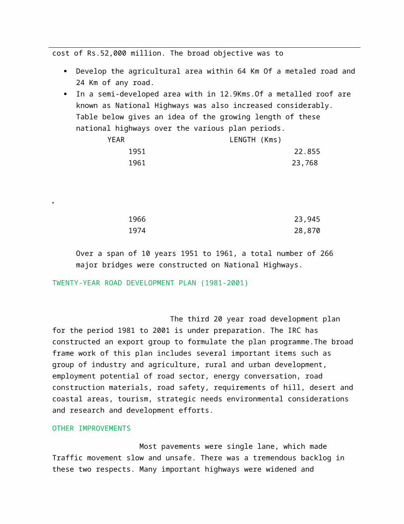
In a semi-developed area with in 12.9Kms.Of a metalled roof are known as National Highways was also increased considerably. Table below gives an idea of the growing length of these national highways over the various plan periods. YEAR LENGTH (Kms) 1951 22.855 1961 23,768
.
1966 23,945 1974 28,870
Over a span of 10 years 1951 to 1961, a total number of 266 major bridges were constructed on National Highways.
TWENTY-YEAR ROAD DEVELOPMENT PLAN (1981-2001)
The third 20 year road development plan for the period 1981 to 2001 is under preparation. The IRC has constructed an export group to formulate the plan programme.The broadframe work of this plan includes several important items such as group of industry and agriculture, rural and urban development, employment potential of road sector, energy conversation, road construction materials, road safety, requirements of hill, desert andcoastal areas, tourism, strategic needs environmental considerations and research and development efforts.
OTHER IMPROVEMENTS
Most pavements were single lane, which made Traffic movement slow and unsafe. There was a tremendous backlog in these two respects. Many important highways were widened and
strengthened to provide easy slow of traffic. Therefore apart from quantitative increase in kilometer age. There has been a marked qualitative improvement in the highways all over the country.
In the fifth five year plan the first priority was given to those works which were already on hand. The plan also makes a provision for four lane Highways for sections, which are hiked with Traffic.
NEGLIGENCE OF ROADS
The public accounts committee in its 132nd report has charged the Government with ‘negligence of roads ‘the development of national Highways in the country. This was evident from the meager addition of 99 Kms. In 34 years, the total length of national highways as a March 31, 1981, was only 31,358 Kms for a short of the Target of 51,210 Kms. Laid down in 20 years of plan (1961-1981).
Road Transport contributes substantial revenues to the national exchequer. While the total revenue collected from Road transport was about Rs.7, 666 crores. During 1974-75to1978-79.The amount spent on development and maintenance the period was 2,955.07 crores.
The committee expressed concern over the conditions of National Highways and said they suffered from defencies likes missing links, weak and over aged bridges and culverts.
To remedy this, the committee has recommended a time-bounded programmed not exceeding 10 years for removing defencies in thus National High Ways
REPORT
The proposed road near Balji Link Bus Stand, which was located towards north of the Tirupati Town. The Road is perpendicular to Bye=pass and connects Hare Rama Hare Krishna Road.This road has much importance for the people who are residing there. The vehicle Trafficin future is expecting more and similarly the pilgrim movement also.
The General soil conditions of that locality are as follows:
1. Hard gravelly soil having boulders2. Max.undulations due to hill area.3. Soil color is Red and impervious4. The soil contains optimum moisture5. The frictional capacity of soil is good
SPECIFICATIONS AND TECHNICAL DATA OF PROPOSED ROAD
COMPONENT PARTS OF ROAD
Like other engineering structures, roads also required foundation andsuper structure. The component parts of road are listed as below.
Sub grade Sub base course Base course Wearing course
i. SUB GARADE The top surface of the ground or formation on which the road rests is called sub-grade. It should have sufficient strength to bear the loads and good facilities. It serves the following functions.
(i).It supports the road structure. (ii).It forms a bed for the road at the designed level.
ii. SUB-BASE COARSE The layer between the sub-grade and base course which isformed by lacing locally available cheap materials is known as sub-base course. If the strength and drainage of the land is in good condition, sometime sub-base course is omitted .It serves as the following functions.
a) To protect the sub-gradeb) To improve the drainage
c) To reduce the intensity of land on the sub-graded) To protect the base and wearing course from the
poor qualities of sub grade such as swelling, shrinkage, settlement etc.
e) To permit the building of relatively thick pavement at a cost in the case of flexible pavements.
iii. BASE COARSE The important structural partof a road that is below the wearing coarse is known as base course. It shouldbe strong enough to bear the loads of traffic and is generally constructed withgood material slike broken stones well compacted. Its functions are:
a) To support the wearing coarse and prevent distributions in it.
b) To bear the loads of the trafficc) To reduce the intensity of loading on the sub-base
and sub-grade.d) To increase the structural strength of the road.e) To reduce the thickness of wearing coarse.f) To prevent volume changes in the poor sub grade.g) To provide a properly shaped coarse on a roughly
shaped formation.
iv. WEARING COARSE The topmost layer of a road, which is indirect contact with the traffic is known as wearing course. Itshould be capable of withstanding the wearing effects of the Traffic and impervious. Its functions are
a) To provide a smooth surface for the trafficb) To give strength to the road structuresc) To act as cushion between the wheels and
based) To drain away rain water and prevent coition
of water
DETAILS OF RAIN FALL
In Tirupati, the rainfall is heavy when compared to other places in “Rayalaseema”.This is due to “Forests” which is very nearer to Tirupati. In Tirupati, the topography of the land is such that the occurrence of floods is almost nil. The rains will occur only for a period of four months and rainfall ranges from 50 to 75 Km.peryears. The rain fall is mainly in July to September. So consideration of rain fall may not demand provision of tar road cement concrete road. SoW.B.M. road is quite sufficient for its good drainage conditions. It can serve even in rainy season.
JUSTIFICATION FOR PROVIDING WBM ROAD
Main types of Roads are:
1. WBM Road
2. Bituminous Road
3. Spreading coarse aggregate: Coarse aggregate should be spread uniformly and prepared upon the base is required quantities, the aggregates are spread to a profile by completes, no segregation for large and fine aggregates shall be allowed.
4. Rolling: Dry rolling is done by 6 to 10 tones, rolling should begin from edges making longitudinal passes. Rolling should progress from edges to crown, where road is given super progress fromedges to crown, where road is given super elevation rolling should start from lower edge and progress towards outer edge. There should be overlap of half the width of rollers between consecutive rolling’s.
5. Application of screening: After the partial compartment of course aggregate, application of screening in this layers, so as to make them fill the voids, has to be done, three or more applications of
screenings should be made.
6. Sprinkling of water and rolling: The surface is sprinkling with plenty of water, boomed and rolled.
APPLICATION OF BINDING MATERIALS
A thin layer of binding materials is applied. Plenty of water is sprinkled,broomed and rolled, two or more applications should be done.
Rolling is continued till slurry of binding materials and water formsa wave shed of the moving roller wheel.
SETTING AND DRYING
The surface is allowed to overnight. It should be allowed to set and dry completely.
PREPARATION OF SHOULDERS
During curing the shoulders are prepared by filling earthto be specified cross slopes. These are then properly compacted by rolling or tamping.
OPENING TO TRAFFIC
After drying the road is opened to traffic the traffic should be well distributed over the full width of the road by placingobstacles longitudinally in the form of drums, branches of trees, etc., on the road surface. The process of placing such obstacles longitudinally on the newly prepared road surface for distribution oftraffic known as like katai.
Foundations coarse of boulder stone placed on a prepared sub grade preferably a thickness of about 250 mm.
Base Coarse consists of 75 mm to 150 mm thick coarse aggregate of size vary from 40 t0 600mm.
A layer of grid age placed at the top for a thickness of 6to 12mm to be provided.
MACHINERY REQUIRED IN THE CONSTRUCTION OF WBM ROADS
i. Patching of pot holes and removal of ruts.The pot holes should be made into geometric shapes loose materials is used. It is filled with coarse aggregate, watered and compacted with hand reamers.
II.BINDING OF SURFACE
The binding material is applied in thin layers watered, broomed and rolled.
III.SURFACE RENEWAL
This is done when the surface is badly damaged. The existence surface is scarified to depth of 75 mm and the resulting material removed the berms of screening to salvage the usable coarse aggregates.The salvaged coarse aggregate is mixed with quantity of fresh aggregate and a new layer of WBM road is laid.
METHODS OF PREVENTION OF DUST NUISANCE
Sprinkling of water periodically. Application of a coat of road oil. Application of calcium chloride solution. Bituminous surfacing of one or two coats.
GEOMETRIC DESIGN OF HIGH WAY
The physical features of road are known as road geometric. The elements of a highways included in road geometric are:
Cross section of highway elements. Speed of road vehicles. Sight distances. Curves. Super elevation.
This phase of highway design witch deals with the different highways is called “geometrical design of highways”.
BEFORE DESIGNING A HIGHWAY, THE DESIGNER MUST KEPP IN VIEW FOIIOWING BASIC CONDACTIONS:
There should be proper record of survey work done in the field.
There should be sufficient cross sectional dimensions such as carriageway width formation width, right of way, etc.
The road alignment should be economical. There should be easy gradient. There should be adequate camber on straight portion of the
road. There should be proper “super elevation” on curved potion of
the road. There should be efficient drainage of proper system. There should be provision of proper curves. There should be provision of extra road width for curved. There should be provision of sufficient sight distances
available on curves. There should be provision of “road signals” particularly at
road junctions Estimated cost of the project should also be kept in view.
CROSS SECTION OF HIGH WAY ELEMENTS:i. Carriage way: It is the width of road way constructed for
movement of vehicular traffic. The width of carriage way depends on the width of traffic lanes required. According to I.R.C. specifications,the carriage width for single lane traffic is 3.75m.
The factors governments the number of traffic required for a high way are:
a) Type of traffic existing and expected in next 10 year.b) Intensity or traffic expected in next 10 year c) Over all maximum expected width of a vehicle.
Minimum side clearance required for safe driving
2. Shoulders: the portion of road way between the outer edge or carriage and the inner edge of kerb or slop drain is called “shoulders”. It should have sufficient load bearing capacity to support the loaded truck.
OBJECTS:
It serves as service lane to stop the break-down vehicles. They provide lateral stability to the carriageway. They serve as parking places to for vehicles in case of
emergency.
CAMBER:
The convexity provided to the surface of carriage way or the rise given to the centre of carriage say above its edges on straight portion of a road called camber or coarse fall. It is also defined as the slope of the line joining crown to the edges.
I.R.C. RECOMMENDEE CAMBERS FOR DIFFERENT TYPE OF ROADS:
1. For concrete pavement Lin 60 to Lin 59
2. For Bituminous surface Lin 50 to Lin 40
3. For W.B.M. roads Lin 40 to Lin 33
4. For Gravel roads Lin 40 to Lin 33
5. for Earth Roads Lin 33 to Lin 25
OBJECTS OF PROVIDING CAMBER:
1. To drain the rain water.2. To separate the traffic in the directions.3. To improve the appearance of the road.4. To maintain the proper lanes for vehicles.
GRADIENT
The rate or rises or fall given to the information of road in longitudinal direction is called “grade or gradient”. It is expressed as ratio difference in levels of total horizontal length inwhich it occurs.
OBJECTIVES OF PROVIDING GRADIENTS:
1. To connect the stations situated at different levels.2. To make earth work of the road project economical by reducing
the quantity of earthwork in embankment Olin cutting.3. To drain the rain water falling on the road surface effectively.4. To reduce the maintenance cost of the road surface.5. For economical construction of side drains.
TYPES OF GRADIENTS:
1. Ruling Gradient2. Limiting Gradient3. Exceptional Gradient4. Minimum Gradient
Exceptional Gradient: The gradient stepper than limiting gradient which is adopted in exceptional cases in order to avoid deep cutting is known s exceptional cases in order to avoid deep cutting is known as exceptional gradient.IRC suggested values are:
In plains 1 in 15
In hills 1 in 12
Minimum gradients: the minimum desirable slopes essential for effective drainage of rain water from the road surface is called minimum gradient IRC recommended values are:
1in200 if side drains are lined
1in100if side drains are unlined
Design speed:
The maximum safe speed of vehicles assumed for geometrical design of highway is known as design speed.
Factors affecting design speed are:
Type and condition of road surface
1. Structure of the road.2. Nature, type and intensity of traffic.3. Sight distance required.4. Nature of the county.
Sight distance:
The length of the road clearly visible to the driver on either horizontal or curves is known as sight distances.
Factors affecting sight distance are:
1. Speed of vehicle 2. Efficiency of brakes3. Frictional resistance of road surface4. Slope of the road surface5. Height or drivers eyes6. Perception time
7. Break reaction time
Types of sight distance:
1. Stopping sight distance2. Overtaking of sight distance3. Intermediate of sight distance4. Lateral sight distance
1. stopping sight distance: The minimum sight distance available ona highway should be of sufficient length it stop vehicle withoutcollision is known as stopping sight distance
2. Sage overtaking of passing sight distance: the minimum distance needed by a driver on two roads to enable him to overtake another vehicle ahead against the traffic from opposite direction is called over overtaking of passing sight distance. The minimum overtaking sight distance depends upon the followingfactors:1. Rate of acceleration of the overtaken vehicle2. Spacing between vehicles3. Speeds of overtaking and that of vehicle coming from the
opposite direction.
3.Internediate Sight Distance:The distance, which affords reasonable opportunities to drivers to overtake the vehicle ahead with caution, is known as Intermediate Sight Distance.
4. Lateral sight distance:The sight distance needed by the driver of a vehicle who sees another vehicle approaching the interaction reactsand applied drake to bring vehicle to dead stop at the intersections without any collision or accident is called safe sight distance for entering into an intersection or lateral sight distance.
ENGINEERING SURVEYS OF HIGH WAYS LOCATION
The four stages of the engineering surveys involved in thealignment of highway project are:
1. Map study2. Reconnaissance survey.3. Preliminary survey4. Detailed survey of final location survey.
1. MAP STUDY:The process of marking several possible alternative alignments of a road on the topographic map of the area is known as map study of paper location.
The topographic maps are available in Indian from survey of Indian 15 to 30 m. contour intervals. From these maps 2or3 best possible routes are selected i.e. route’s involving less cost and distance and more advantages.
2. RECONNAISSANCE SURVEY: The rapid and rough survey involving the study of physical characters of the area of proposed route is known as “Reconnaissance survey”. This survey is carried out without accurate instruments andclinometers is used to determined slopes.
OBJETCTS OF RECONNAISSNCE SURVEY
To locate the obligatory points along the alternative routes. To determine the value of maximum gradient, radius of curves
along alternate alignments. To collect information regarding the availability of local
construction material and flabbier. To collect geological information for foundation work of bridges
and construction or road pavements. To prepare a rough estimate of the total cost of construction of
the road along each routs. To determine two or more but possible and economical routes for
further study based on practical considerations observed at site.
PRELIMINARY SURVEY:These are of finding the details of alternative alignments found suitable during the reconnaissance. Survey is known as preliminary survey. To do this survey, the instruments used are chain, metallic tape, prismatic compass leveling instruments etc. Its
object is:
1. To select the best route.2. To determine the center line to be followed.3. To collect any additional information found
necessary after reconnaissance.
FINAL LOCATION SURVEY: The survey which involving the location of finally recommended alignment, during preliminary survey on the ground is known as final location survey.
ITS OBJECT ARE
1. To fix the center line of the proposed road on the ground.2. To determine total cost of the road project.3. To collect field data necessary for the acquisition of night of
way.4. To collect other details necessary for drafting or specification
formation of rates, computing designs preparation of construction drawings of working out items and quantities.
CURVES
INTRODUCTION
At the change in alignment or gradient of a road geometrically arcs are provided. That geometrical arc is called curves.
Necessity of providing Curves
To lay the road according to topography of the country. To provide access to the particular place. To avoid costly land. To avoid certain excess cutting or filling. To avoid certain religious, monumental or such other important
structures. To make use of the existing bridge. To make use of the existing right-of-way. To keep the driver alert by making change in the direction of
road. To avoid mental strain caused by the monotony of continuous
journey along a straight route. To check the tendency of the driver to increase the speed of his
vehicle beyond the safe limits on straight routes.
Advantages of Curves:
They provide gradual change in direction. They provide gradual change in gradient. They provide easy turning of vehicles. They provide comfort to the passengers. They increase the life of vehicles. They help to keep the speed of vehicles within limits. They help in providing safe and economical alignment of a
road. They help in providing adequate visibility to the traffic.
Types of curves:
The curves are divided into
o Horizontal Curves o Vertical curvesA. Horizontal Curves:The curves provided to change the direction of
central line of highway are known as horizontal curves. Horizontal curves are further divided into: i. Simple curves.ii. Compound curves.iii. Reverse curves.iv. Transition curves.
Simple Curve: A curve having single arc of uniform diameter connecting two tangents is called as simple curve .This type of
curves is stable for slow moving traffic and for large radius.
Compound curve: A curve having a series of two or more simple curves of different radius connecting two tangents, which turn in the same, direction, is called as compound curve. This type of curve is used when compelled by topography of the area to avoid cutting through hard rocks, heavy cutting of filling.
Reverse curve: A curve having two simple curves of same radii ordifferent radii running in different direction constitutes as reverse curves. This type of curves is generally preferment in the alignment of a hill road.
Transition curve: A curve having a arc of varying radii infiniteto finite constitutes a transverse curve.
The different types of transition curves are:
Spiral Cubic Parabola Lemini Scata
B.VERTICAL CURVES: The curves provided at change of gradient of a road are called vertical curves. Vertical curves are provided where change of gradient is more than 0.5%.
The vertical curves are divided into:
Sumit curves. Valley curves.
Summit curves: The vertical curves having their convexity upward are known as summit curves. These curves are provided when a rising gradient intersects a falling gradient or a rising gradient meets another rising gradient.
Valley curves:The vertical curves having their convexity downwards are known as valley curves. These curves are provided when a falling gradient intersects a rising gradient meets another falling gradient.
Super Elevation: The rise given to the outer edge of a road above the
inner edge on curves is known as super elevation.
NECESSITY:
To counteract the effect of centrifugal force acting on the moving vehicle to pull the same outward on horizontal curve.
To help fast moving vehicle to negotiate a curved path without overturning and skidding.
To ensure safety to the fast moving traffic. To prevent damaging effect on the road surface due to improper
distribution of load.
ROAD DRAINAGE
INTRODUCTION: The process of removing and controlling the access of surface and sub-surface water of a road is called road drainage.
NECESSITY OF ROAD DRAINAGE:
i. To prevent the softening of the road surface and formation ofrubs.
ii. To prevent the sub grade from losing is bearing capacity.iii. To prevent slipping of side slopes of formations.iv. To prevent erosion of surface and side slopes of formations.
1.SURFACE DRAINAGES: The system consisting of collection of disposal of surface water within right of way of road is called surface drainage. The surface water is first collected in longitudinal suitable side drains which are then disposed of in the nearest stream or valley etc. To make the surface drainage system, the following are followed.
Impervious road surface Camber and longitudinal Gradient
Side drains to collect water Catch water drains in cutting Kerb gates in urban roads to collect
surface water.
2.SUB SURFACE DRAINAGE: The system of collection and removal of sub-soil water from under side of road pavement is called sub-surface drainage. This type of drainage system is adopted whenever the following situation arises.
When the road is through a flat country and the ground water table is at higher levels.
When the pavement structure is subjected to the action of spring.
When the road is in cutting and there is considerable seepage through the side slopes.
When the road is at the foot of a hill and water from there may seep into the road sub grade.
When there is a danger of rise of moisture to the pavement structure due to capillary rise, even if the water table column is at lower levels.
The following measures are to be taken to make the subsurface drainage system more effective:
Control of seepage flow providing intercepting drains. Lowering water table column by providing longitudinal and
lateral drains. Providing surface dressing to the formation.3.CROSS DRAINAGE:
The system of disposing the water collected in the side drains or that of the natural streams across a road is known as “cross drainage”. The cross drainage system consists of providing cause ways, culverts, bridges etc., at the place wherestream have to cross the road.
4.SIDE DRAINS:The drains provided parallel to the road for
collecting and disposal of surface water are known as side drains. The usual shape of side drains are in trapezoidal section. The side drains are classified into:
Open drains Closed drains
OPEN DRAINS:
The side constructed without any filter material and remain open to view is known as “Open Drains”. These types of side drains are generally provided.
In rural area when the designed depth of side drains is less. At the sides of road subjects to light traffic. These drains
can be cheaply and easily constructed and maintained.
CLOSED DRAINS:
The side drains covered at their top is known asclosed drains. These type of drains are provided.
Parallel to the road subjects to heavy traffic. And both in rural and urban areas.
These drains are costly and difficult to construct and to maintain.
ATTERBERG'S LIMITS:-
LIQUID LIMT:
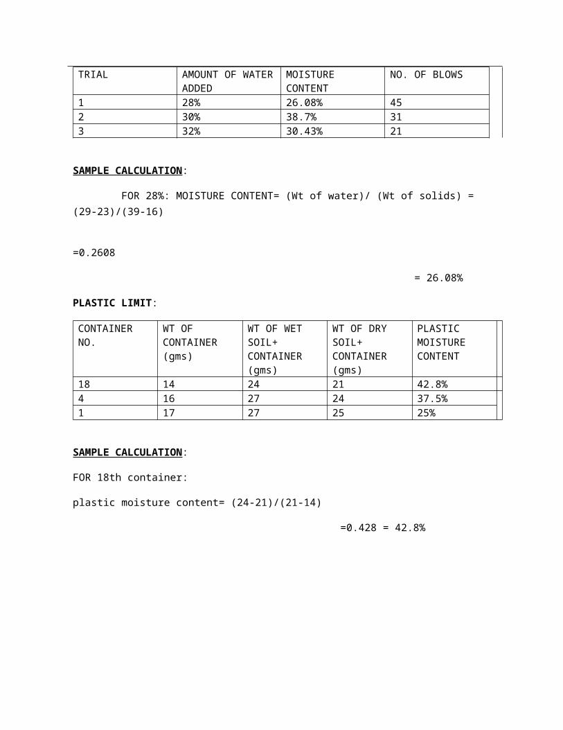
TRIAL AMOUNT OF WATERADDED
MOISTURE CONTENT
NO. OF BLOWS
1 28% 26.08% 452 30% 38.7% 313 32% 30.43% 21
SAMPLE CALCULATION:
FOR 28%: MOISTURE CONTENT= (Wt of water)/ (Wt of solids) = (29-23)/(39-16)
=0.2608
= 26.08%
PLASTIC LIMIT:
CONTAINER NO.
WT OF CONTAINER (gms)
WT OF WET SOIL+ CONTAINER (gms)
WT OF DRY SOIL+ CONTAINER (gms)
PLASTIC MOISTURE CONTENT
18 14 24 21 42.8%4 16 27 24 37.5%1 17 27 25 25%
SAMPLE CALCULATION:
FOR 18th container:
plastic moisture content= (24-21)/(21-14)
=0.428 = 42.8%

COMPACTION TEST :-
Sno. PARTICULARS
1 2 3 4 5 6 7
1 Water content added
6% 8% 10% 12% 14% 16% 18%
2 Wt of mould (w1) gms
5695 5695 5695 5695 5695 5695 5695
3 Wt of mould + compactedsoil (w2)gms
7443 7463 7621 7705 7743 7755 7675
4 Wt of compactedsoil w= (w1-w2) gms
1748 1768 1926 2010 2048 2055 1980
5 Wet density (r wet) gm/cc
1.748 1.768 1.926 2.010 2.048 2.055 1.980
6 Containerno.
5 17 10 6 24 9 22
7 Wt of container+ wet soil( gms)
54 82 53 52 57 78 75
8 Wt of container+ dry soil (gms)
51 76 49 48 54 69 66
9 Empty wt of container(gms)
16 16 12 13 13 13 13
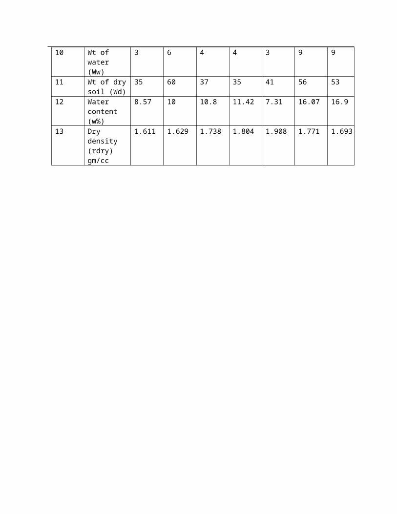
10 Wt of water (Ww)
3 6 4 4 3 9 9
11 Wt of drysoil (Wd)
35 60 37 35 41 56 53
12 Water content (w%)
8.57 10 10.8 11.42 7.31 16.07 16.9
13 Dry density (rdry) gm/cc
1.611 1.629 1.738 1.804 1.908 1.771 1.693