department of physics - edo university
TRANSCRIPT
EDO UNIVERSITY IYAMHO
Department of Physics PHY 213 - Electric Circuit & Electronics (3 Credit Unit)
Instructor: Dr A.S. OLAYINKA
Email: [email protected]
Phone: +234- 8062447411
Lectures: Wednesday, 10.00am – 12.00 pm
Thursday, 8.00 - 9.00am
Venue: PHYSICS LAB., Faculty of Science
Office: Faculty of Science, New Building, Room
Office hours: Wednesday: 12.00 - 2.00 pm
Description: This course is intended to give the students a thorough knowledge of direct current
(D.C) circuits, alternating current (A.C) circuits and introduction to basic electronics. This course
covers advanced topics in semiconductors, the p-n junction, field effect transistors, bipolar
transistors, characteristics and equivalent circuits, amplifiers, feedback, and oscillators.
Prerequisites: PHY 121 is a prerequisite to this course. Students are expected to be familiar with
the concepts the basic electricity and magnetism.
Assignments: Assignments are due for submission on Wednesday at 8.00am the next week, unless
otherwise noted. Assignment There We expect to have five individual homework assignments
throughout the course in addition to a mid-semester Test and a final examination.
Grading: We will assign 10% of this class grade to home works and assignments, 05% for
attendance, 15% for the mid-semester test and 70% for the final examination. The final
examination is comprehensive.
Course Materials:
Lecture notes and presentation are available at the EUI-LMS.
Learning outcomes: At the completion of this course, students (learners) are expected to:
i. Appreciate that electrical systems may be represented by circuit diagram
ii. Identify basic electrical circuit symbols
iii. Understand the units of electrical current, potential difference (p.d) and resistance to be
amperes (A), volt (v) and ohm (Ω) respectively
iv. Understand sources of EMF
v. Understand Network theorems and use the same for network analysis and calculation
vi. Understand the principle of transformer
vii. Understand Basic Electronics
viii. Understand Semiconductor theory and its application to electronics

ix. Understand principles of PN junction, BJT and FET
x. Design a simple circuit e.g. Voltage divider, power supply
Software Requirement:
MATLAB, JAVA
Reference Books:
The recommended and referenced textbooks for this class are:
Title: Electrical and Electronic Principles and Technology (available in library)
Author: John Bird
ISBN: 978-0-75-068556-6
Publisher: Newnes, UK, USA
Edition: 3rd Edition, 2007
Title: Electronic Devices and Circuits (available in library)
Author: Dr. K. Lal Kishore ISBN: 81-7800-167-5
Publisher: BS Publications, Hyderabad
Title: A Textbook of Electrical Technology
Authors: B.L. Theraja and A.K. Theraja
ISBN: 81-219-2441-3
Publisher: S. Chand & Company Ltd.
MODULE 1 - D.C. CIRCUITS; KIRCHHOFF’S LAWS, SOURCES OF EMF
Intended Learning Outcome:
At the end of this module, the students (learners) are expected to:
• Appreciate that electrical systems may be represented by circuit diagram
• Identify basic electrical circuit symbols
• Understand the units of electrical current, potential difference (p.d) and
resistance to be amperes (A), volt (v) and ohm (Ω) respectively
• Understand sources of EMF
• Appreciate that the unit of charge is the coulomb
• Understand that a potential difference between two points in a circuit is
required for current to flow
• Recognise that resistance opposes current flow and is measured in ohms
• Appreciate what an ammeter, a voltmeter, an ohmmeter, a multimeter and an
oscilloscope measure
• State Ohm’s law mathematically as V =IR or I =V/R or R=V/I
• Use Ohm’s law in circuit analysis and calculations
• State Kirchhoff's circuit laws
• Use Kirchhoff's circuit laws in circuit analysis and calculations
• Appreciate that electrical power P is given by P=VI =I2R=V2/R with unit in
watts
1.1 D.C. Circuit
A Direct Current (DC) circuit is an electric circuit in which Current (I) flows through
in one direction. DC circuits are usually found in many low-voltage applications,
especially where these are powered by Battery.
Most electronic circuits require a DC power supply for their operations. Common
devices / gadgets that use DC power supply are Television, Laptop, Mobile phones,
Tablets, Computers, etc.
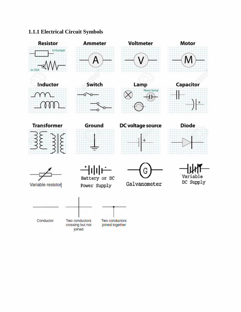
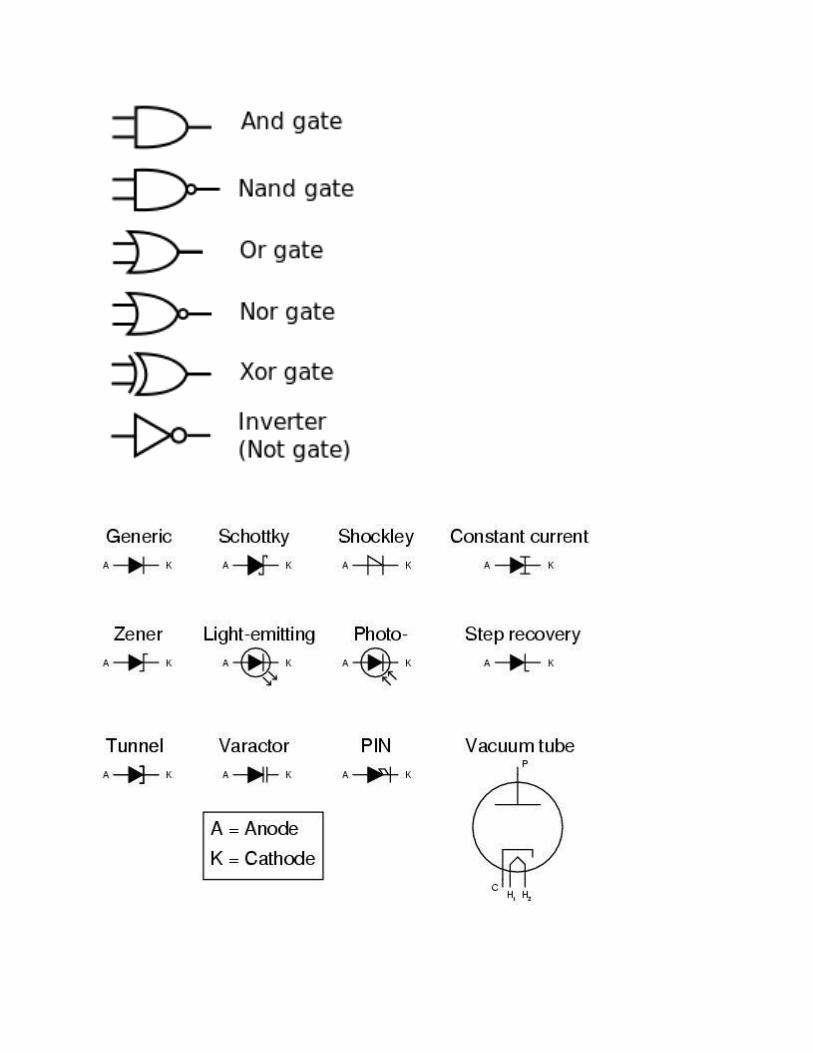
1.1.1 Electrical Circuit Symbols
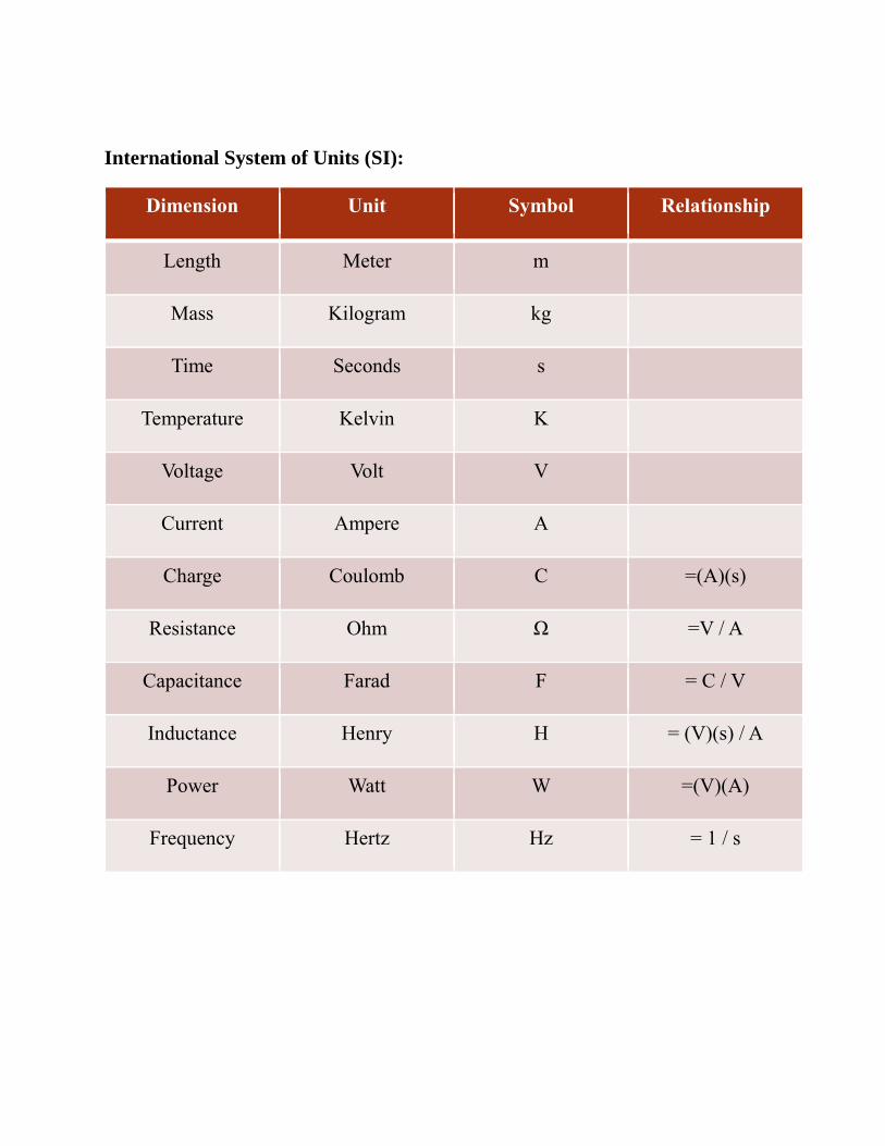
International System of Units (SI):
Dimension Unit Symbol Relationship
Length Meter m
Mass Kilogram kg
Time Seconds s
Temperature Kelvin K
Voltage Volt V
Current Ampere A
Charge Coulomb C =(A)(s)
Resistance Ohm Ω =V / A
Capacitance Farad F = C / V
Inductance Henry H = (V)(s) / A
Power Watt W =(V)(A)
Frequency Hertz Hz = 1 / s
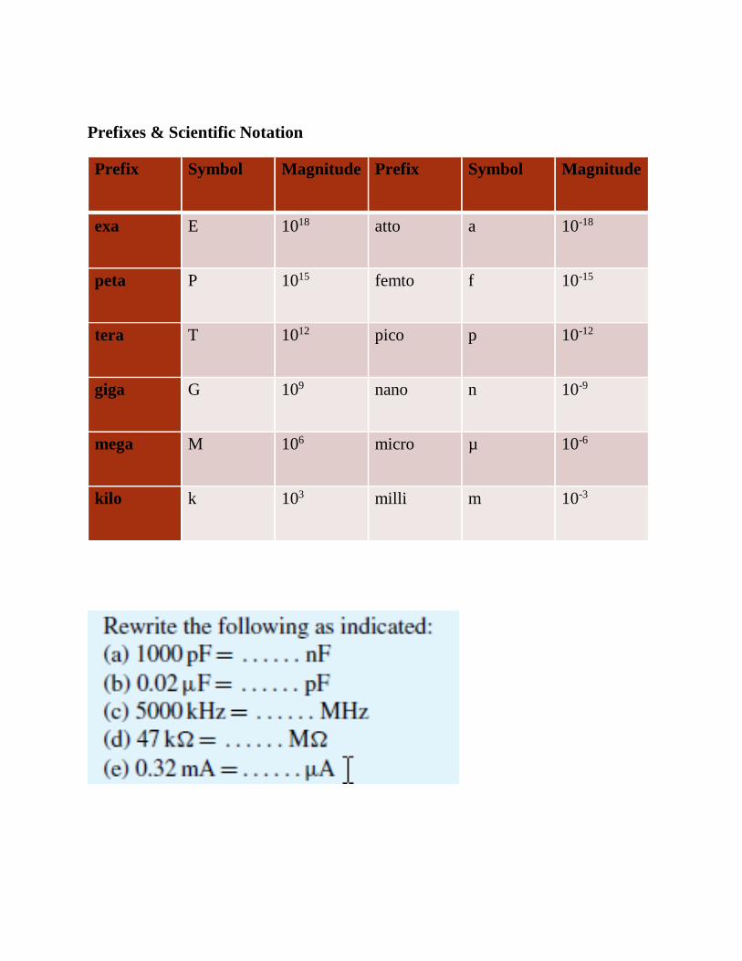
Prefixes & Scientific Notation
Prefix Symbol Magnitude Prefix Symbol Magnitude
exa E 1018 atto a 10-18
peta P 1015 femto f 10-15
tera T 1012 pico p 10-12
giga G 109 nano n 10-9
mega M 106 micro µ 10-6
kilo k 103 milli m 10-3
1.2 Charge and quantity of electricity:
The unit of charge is the coulomb (C) where one coulomb is one ampere second. (1
coulomb = 6.24 × 10¹⁸ electrons).
Coulomb is defined as the quantity of electricity which flows past a given point in
an electric circuit when a current of one ampere is maintained for one second.
Charge, Q=It
where I is the current in amperes (A) and t is the time in Seconds (s) .
Example:
If a current of 6A flows for 4 minutes in a circuit, find the quantity of electricity
transferred.
Solution:
I = 6A, t = 4 × 60 = 240 s
Q = 6 × 240 = 1440C = 1.44 x 10³C = 1.44kC
1.3 Electrical potential and e.m.f.:
• The unit of electric potential is the volt (V), where one volt is one joule per
coulomb.
• One volt is defined as the difference in potential between two points in a
conductor which, when carrying a current of one ampere, dissipates a power
of one watt, i.e.
𝒗𝒐𝒍𝒕𝒔 = 𝒘𝒂𝒕𝒕𝒔
𝒂𝒎𝒑𝒆𝒓𝒆𝒔 =
𝒋𝒐𝒖𝒍𝒆𝒔/𝒔𝒆𝒄𝒐𝒏𝒅
𝒂𝒎𝒑𝒆𝒓𝒆𝒔=
𝒋𝒐𝒖𝒍𝒆𝒔
𝒂𝒎𝒑𝒆𝒓𝒆𝒔 𝒔𝒆𝒄𝒐𝒏𝒅=
𝒋𝒐𝒖𝒍𝒆𝒔
𝒄𝒐𝒖𝒍𝒐𝒎𝒃𝒔
• A change in electric potential between two points in an electric circuit is
called a potential difference.

• The electromotive force (e.m.f.) provided by a source of energy such as a
battery or a generator is measured in volts.
1.4 Resistance and conductance
The unit of electric resistance is the ohm(Ω)
One ohm is one volt per ampere.
1Ω is defined as the resistance between two points in a conductor when a constant
electric potential of one volt, applied at the two points produces a current flow of
one ampere in the conductor.
R = V / I
The reciprocal of resistance is called conductance, G and is measured in siemens
(S).
G = 1 / R = I / V
Example: Find the conductance of a conductor of resistance:
(a) 100 Ω (b) 50 k Ω (c) 150m Ω.
1.5 Electrical power and energy
• When a direct current of I amperes is flowing in an electric circuit and the
voltage across the circuit is V volts, then power, in watts P =VI
• Electrical energy = Power×time = VIt joules
• Although the unit of energy is the joule, when dealing with large amounts of
energy, the unit used is the kilowatt hour (kWh) where
• 1 kWh = 1000watt hour = 1000 × 3600 watt seconds or joules = 3 600 000 J
Example:
A source e.m.f. of 5V supplies a current of 3A for 10 minutes. How much
energy is provided in this time?
Solution:
Energy = power×time, and power=voltage×current.
Energy = VIt = 5 × 3 × (10 × 60)
= 9000 Ws or J = 9kJ
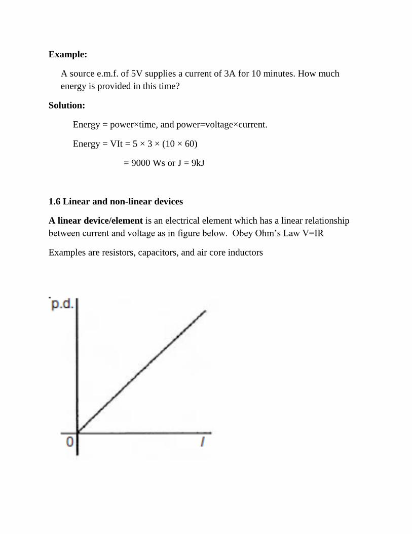
1.6 Linear and non-linear devices
A linear device/element is an electrical element which has a linear relationship
between current and voltage as in figure below. Obey Ohm’s Law V=IR
Examples are resistors, capacitors, and air core inductors

A non-linear element / device is an electrical element which does not have a
linear relationship between current and voltage. Does not obey Ohm’s law
• Examples are diode, transistor, iron-core inductors, vacuum tubes.
1.7 Ohm’s law
• Ohm’s law states that the current I flowing in a circuit is directly
proportional to the applied voltage V and inversely proportional to the
resistance R, provided the temperature remains constant. Thus,
• I = V / R or V = IR or R = V / I
Example: A 100W electric light bulb is connected to a 250V supply. Determine
(a) the current flowing in the bulb, and (b) the resistance ofthe bulb.
Solution:
(a) I= P/V = 100/250 = 0.4A
(b) R = V / I = 250 / 0.4 = 625Ω
1.8 Conductor and Insulator
• A conductor is a material having a low resistance which allows electric
current to flow in it.
• All metals are conductors
• Examples are copper, aluminium, brass, platinum, silver, gold and carbon.
• An insulator is a material having a high resistance which does not allow
electric current to flow in it.
• Example are plastic, rubber, glass, porcelain, air, paper, cork, mica, ceramics
and certain oils.
1.9 Sources of EMF
A battery is a device that converts chemical energy to electricity.
The electromotive force (e.m.f.), E, of a cell is the p.d. between its terminals when
it is not connected to a load (i.e. the cell is on ‘no load’).
The e.m.f. of a cell is measured by using a high resistance voltmeter connected in
parallel with the cell.
The voltmeter must have a high resistance otherwise it will pass current and the
cell will not be on ‘no-load’
The voltage available at the terminals of a cell falls when a load is connected. This
is caused by the internal resistance of the cell which is the opposition of the
material of the cell to the flow of current.
The internal resistance acts in series with other resistances in the circuit.
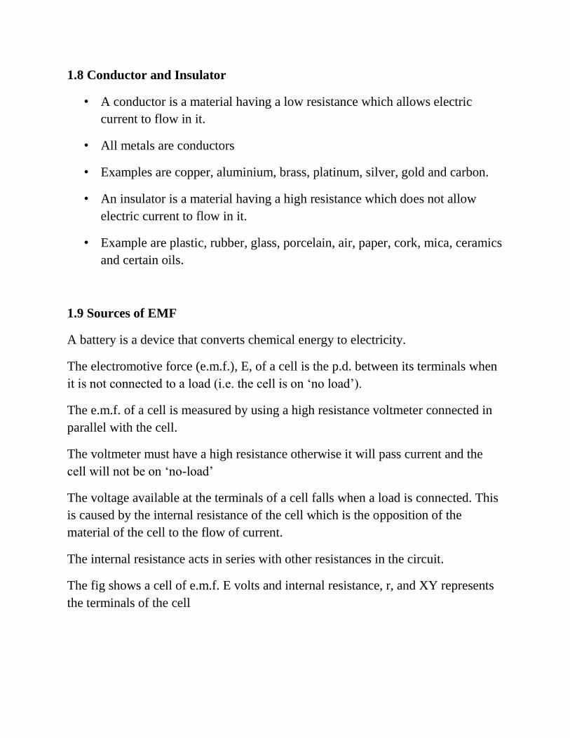
The fig shows a cell of e.m.f. E volts and internal resistance, r, and XY represents
the terminals of the cell
When a load (shown as resistance R) is not connected, no current flows and the
terminal p.d., V =E. When R is connected a current I flows which causes a voltage
drop in the cell, given by Ir. The p.d. available at the cell terminals is less than the
e.m.f. of the cell and is given by V = E – Ir
Since V =E −Ir then the internal resistance may be calculated using
r = (E − V) / I
A battery is a combination of more than one cell. The cells in a battery may be
connected in series or in parallel
• For cells connected in series:
Total e.m.f.=sum of cell’s e.m.f.s
Total internal resistance=sum of cell’s internal resistances
• For cells connected in parallel:
If each cell has the same e.m.f. and internal resistance:
Total e.m.f.=e.m.f. of one cell
Total internal resistance of n cells = (1 / n ) × internal resistance of one cell.

For cells connected in series: (Positive to Negative)
For cells is series with a faulty cell the full voltage supply will be disrupted.
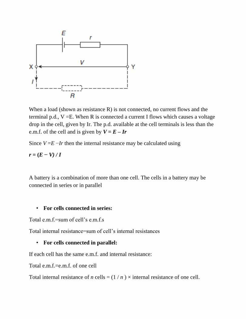
For cells connected in parallel: (Positive to Positive and Negative to Negative)
With parallel cells, capacity in Ah and runtime increases while the voltage stays the same.
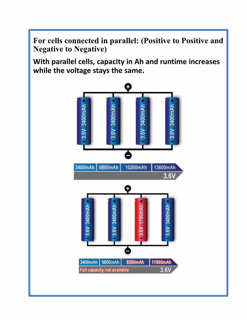
1.10 Series and Parallel Circuit
Series and Parallel Circuit
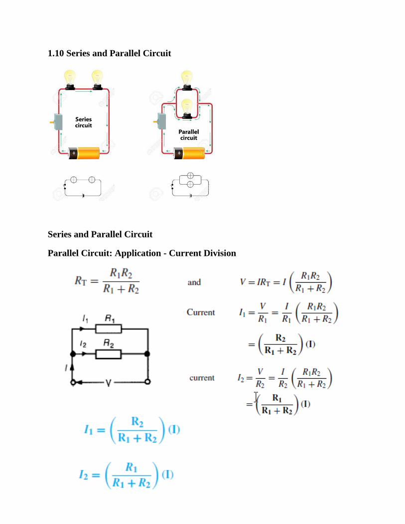
Parallel Circuit: Application - Current Division
1.11 Kirchhoff’s Law
We have Kirchhoff’s Current Law (KCL) and Kirchhoff’s Voltage Law
(KVL)
In understanding the Laws, we define:
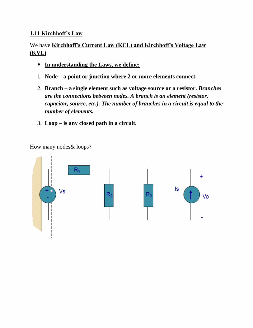
1. Node – a point or junction where 2 or more elements connect.
2. Branch – a single element such as voltage source or a resistor. Branches
are the connections between nodes. A branch is an element (resistor,
capacitor, source, etc.). The number of branches in a circuit is equal to the
number of elements.
3. Loop – is any closed path in a circuit.
How many nodes& loops?
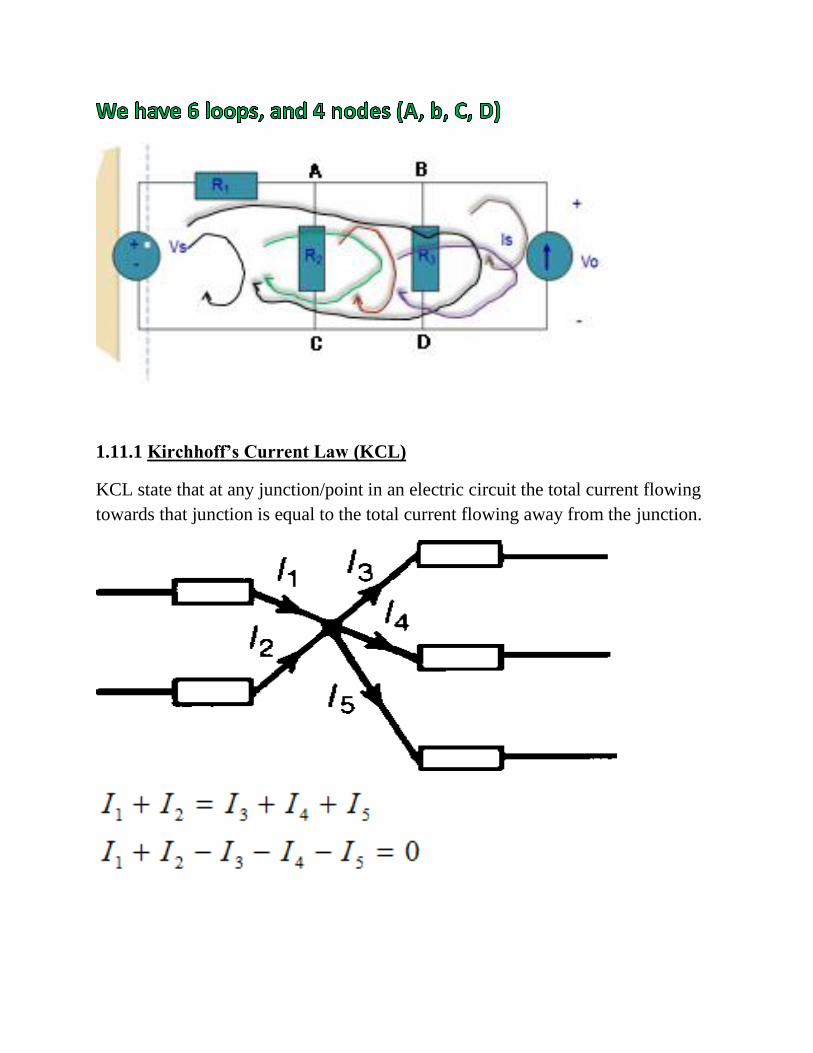
1.11.1 Kirchhoff’s Current Law (KCL)
KCL state that at any junction/point in an electric circuit the total current flowing
towards that junction is equal to the total current flowing away from the junction.
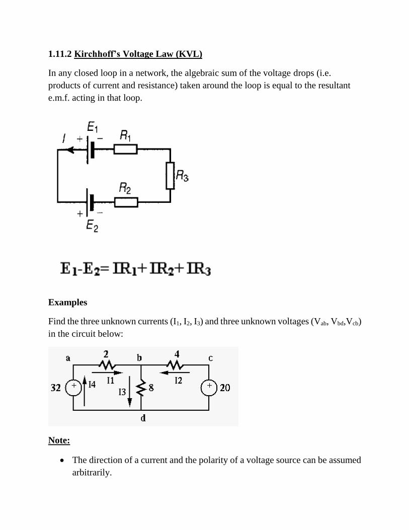
1.11.2 Kirchhoff’s Voltage Law (KVL)
In any closed loop in a network, the algebraic sum of the voltage drops (i.e.
products of current and resistance) taken around the loop is equal to the resultant
e.m.f. acting in that loop.
Examples
Find the three unknown currents (I1, I2, I3) and three unknown voltages (Vab, Vbd,Vcb)
in the circuit below:
Note:
• The direction of a current and the polarity of a voltage source can be assumed
arbitrarily.
• To determine the actual direction and polarity, the sign of the values also
should be considered. For example, a current labeled in left-to-right direction
with a negative value is actually flowing right-to-left.
All voltages and currents in the circuit can be found by either of the following two
methods, based on either the KVL or KCL.
The loop-current method based on KVL:
1. For each of the independent loops in the circuit, define a loop current around the loop in
clockwise (or counter clockwise) direction. These loop currents are the unknown
variables to be obtained.
2. Apply KVL around each of the loops in the same clockwise direction to obtain
equations. While calculating the voltage drop across each resistor shared by two loops,
both loop currents (in opposite positions) should be considered.
3. Solve the equation system with equations for the unknown loop currents.
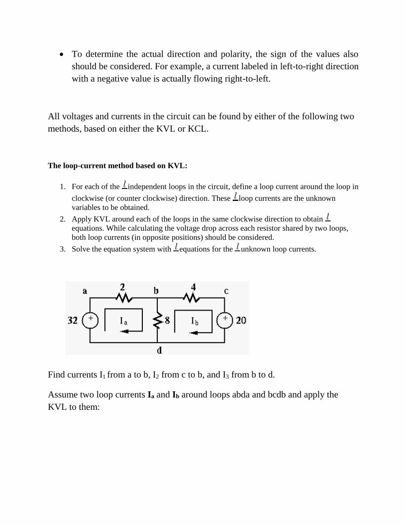
Find currents I1 from a to b, I2 from c to b, and I3 from b to d.
Assume two loop currents Ia and Ib around loops abda and bcdb and apply the
KVL to them:
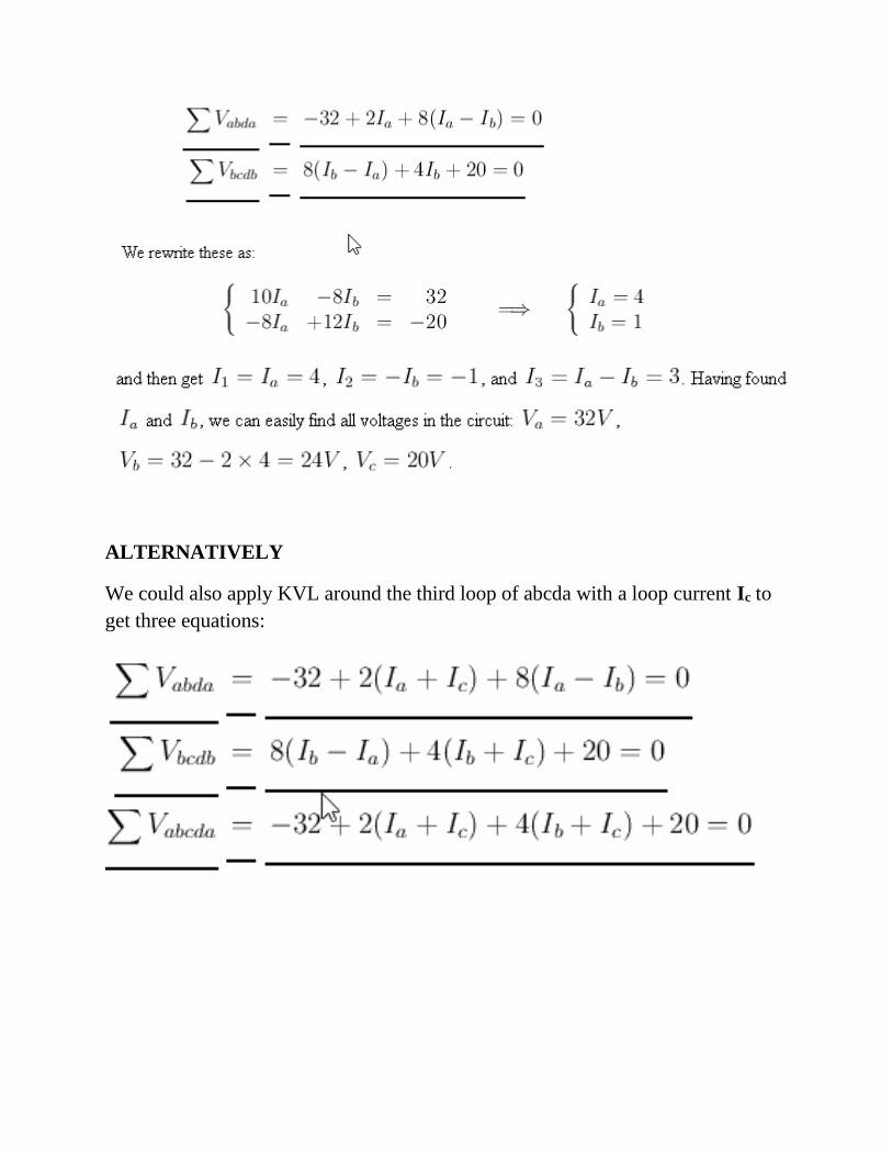
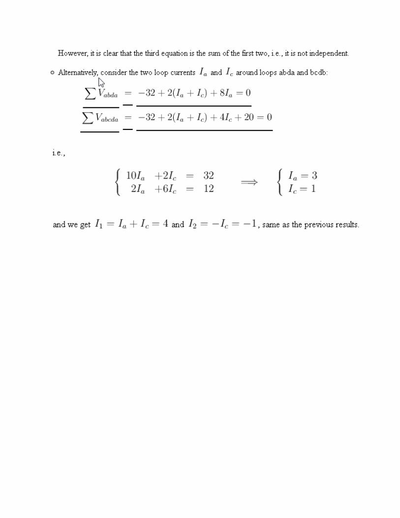
ALTERNATIVELY
We could also apply KVL around the third loop of abcda with a loop current Ic to
get three equations:

References:
John Bird . Electrical and Electronic Principles and Technology. Newnes, UK, USA. 3rd
Edition, 2007
Dr. K. Lal Kishore. Electronic Devices and Circuits .BS Publications, Hyderabad
B.L. Theraja and A.K. Theraja. Textbook of Electrical Technology. S. Chand & Company Ltd.
http://fourier.eng.hmc.edu/e84/lectures/ch2/node2.html