data sheet - deif
TRANSCRIPT

TCM-2 Thyristor Control Module DATA SHEET TCM-2 Thyristor Control Module
DATA SHEET
• Individual cylinder knocking detection • Detection for each combustion • FFT background noise filtering • Highly precise level detection • Individual cylinder misfire detection • CAN bus communication
Document no.: 4921240419C
Anti Knocking System, AKR 3
DATA SHEET
Data sheet Anti Knocking System, AKR 3
DEIF A/S Page 2 of 9
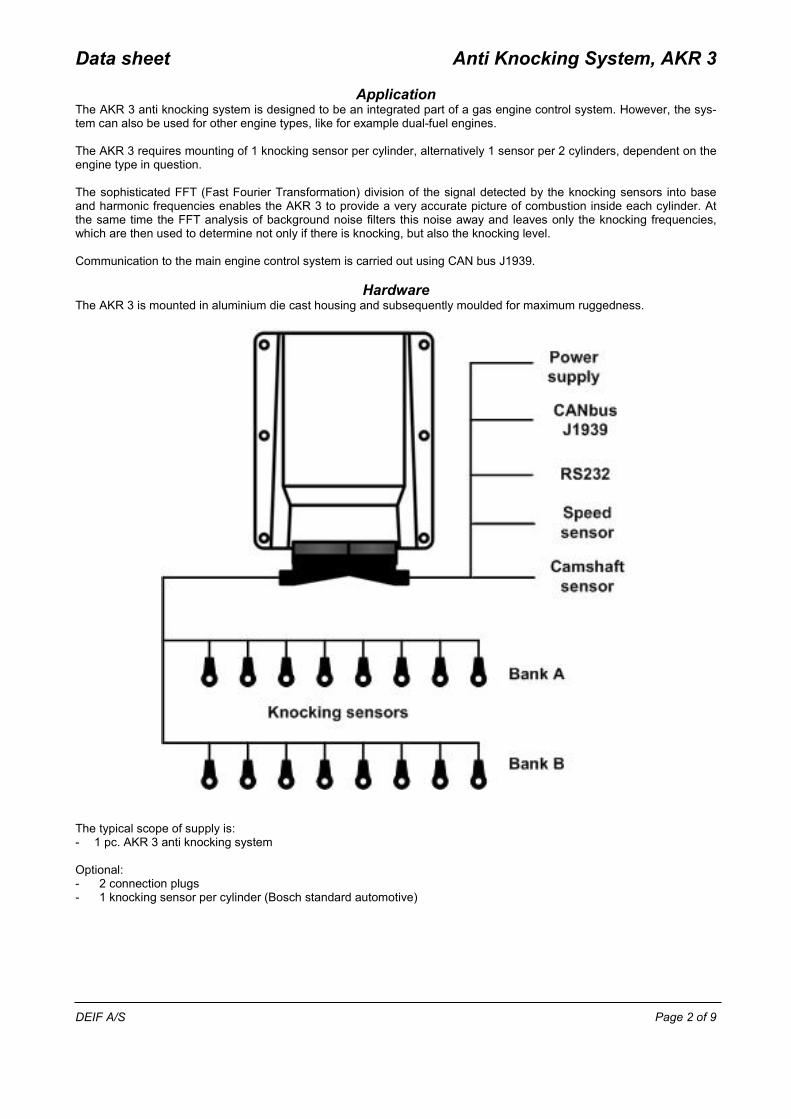
Application The AKR 3 anti knocking system is designed to be an integrated part of a gas engine control system. However, the sys-tem can also be used for other engine types, like for example dual-fuel engines. The AKR 3 requires mounting of 1 knocking sensor per cylinder, alternatively 1 sensor per 2 cylinders, dependent on the engine type in question. The sophisticated FFT (Fast Fourier Transformation) division of the signal detected by the knocking sensors into base and harmonic frequencies enables the AKR 3 to provide a very accurate picture of combustion inside each cylinder. At the same time the FFT analysis of background noise filters this noise away and leaves only the knocking frequencies, which are then used to determine not only if there is knocking, but also the knocking level. Communication to the main engine control system is carried out using CAN bus J1939.
Hardware The AKR 3 is mounted in aluminium die cast housing and subsequently moulded for maximum ruggedness. The typical scope of supply is: - 1 pc. AKR 3 anti knocking system Optional: - 2 connection plugs - 1 knocking sensor per cylinder (Bosch standard automotive)
Data sheet Anti Knocking System, AKR 3
DEIF A/S Page 3 of 9
Protection functions
Heavy knocking alarm for each individual cylinder if the maximum knock energy is exceeded. Knocking alarm for each individual cylinder if the maximum control value is reached. Knock sensor error, speed sensor error, configuration error, internal error. Optional: Misfiring alarm for each cylinder, detected for each individual ignition.
Historical logs Short term and long term diagnostics and parameter changes are logged.
Data transmitted on CAN bus Ignition retard value (knock control) for each cylinder Knocking level for each cylinder Alarm information Diagnostic and status information Optional: Misfiring information for each cylinder
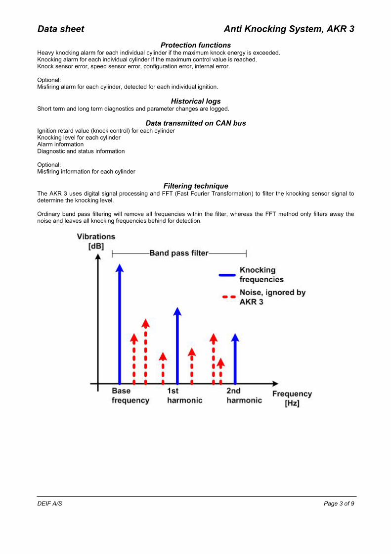
Filtering technique The AKR 3 uses digital signal processing and FFT (Fast Fourier Transformation) to filter the knocking sensor signal to determine the knocking level. Ordinary band pass filtering will remove all frequencies within the filter, whereas the FFT method only filters away the noise and leaves all knocking frequencies behind for detection.

Data sheet Anti Knocking System, AKR 3
DEIF A/S Page 4 of 9
Methane number
Time
Power100%power
Retard
Max.retard
Power output gained
Firing angle retard
The AKR 3 capacity to provide individual knocking data for each cylinder can, if combined with ignition systems capable of handling individual firing angle retard, be used to control the firing angle for each cylinder. Combined with the retard before power reduction approach to knocking prevention, the system offers an improved utilisa-tion of the engine. This feature is especially useful if the fuel used is of varying quality, like for example biogas or landfill gas. Example: As the methane number (quality) of the gas drops, the AKR 3 will provide knocking information to the engine control-ler/ignition system which will initiate a retard (lowering) of the pre-top piston position firing angle. During firing retard control, the maximum engine power output remains the same. If the gas quality decay continues, the firing retard will eventually meet the maximum allowable angle, and from this point on the maximum engine power output will be derated. So, from the start of the retard until maximum retard is reached, there will be no change in the engine power output. Compared to more traditional systems where the power derate is used immediately to prevent knocking, total kWh output is increased.

Data sheet Anti Knocking System, AKR 3
DEIF A/S Page 5 of 9
Configuration
The AKR 3 has to be configured with an engine specific .get file. This .get file includes among other things the engine specific filter parameter for knock detection. If the engine in question is not in our .get library, it is necessary to carry out an AKR calibration on the engine to determine the knock signal and the background noise. This calibration is only neces-sary once for each engine type, and there is a good chance that your engine is already in the library. Contact DEIF A/S to check. If the engine type in question is not in the library, the calibration must be carried out. This can only be done by a DEIF employee. FFT analysis: Calibration tool:

Data sheet Anti Knocking System, AKR 3
DEIF A/S Page 6 of 9
Protection of inputs and outputs
Input short circuit: With the system powered at 75 % to 133 % of nominal system supply voltage over the operating temperature range, the system will survive a short circuit between any input and the battery positive or negative cables. The control unit will not be damaged or forced into an unsafe operating mode. Output short circuit: The CAN data link is according to the J1939 standard. The driver outputs and inputs are short circuit proof including short to 32 V DC supply voltage at ambient room temperature. RS-232 port: The RS-232 port is only used for update and diagnostic purposes by DEIF personnel and must be disconnected during engine operation.

Data sheet Anti Knocking System, AKR 3
DEIF A/S Page 7 of 9
Technical specifications
Operating tempe-rature
-25 to 105 °C (-13 to 221 °F)
Storage tempera-ture
-40 to 105 °C (-40 to 221 °F)
Climate 97 % RH to IEC 60068-2-30 Operating altitude 0 to 4000 m above sea level Aux. supply 20 to 32 V DC
Max. 400 mA Inputs, vibration Up to 24 sensor signals
Sensor type: Bosch Inputs, speed 1 camshaft sensor input
1 crankshaft sensor input (optional) Range: 300 to 2800 RPM Pickup type required: Differential Hall effect sensor with push-pull output stage or inductive sen-sor
Communication 1 × CAN bus J1939 1 × RS-232 for PC tool
Mounting Any direction Safety To EN 61010-1, installation category III, 24 V DC, pollution degree 2 EMC/CE To EN 61000-6-2, EN 61000-6-4
IEC 60533 Power distribution zone IACS UR E10 Power distribution zone
Vibration Amplitude +/-1.6 mm, acceleration +/-4.0 g Test frequency 30 Hz if no resonance frequencies are found Duration 90 min To IEC 60068-2-6/Test Fc & IACS UR E10
Shock 50 g, 11 ms, half sine. To IEC 60068-2-27 Material Housing: Aluminium
Connectors: Polyamide PA66 materials according to UL94 (HB) Additional connector cover for UL and Marine approvals: Plastic material self-extinguishing ac-cording to UL94 (V0)
Plug connections AMP Protection IP65 to IEC/EN 60529 Approvals CE marking
Inquire for marine approvals at DEIF A/S Weight 1.5 kg

Data sheet Anti Knocking System, AKR 3
DEIF A/S Page 8 of 9
Unit dimensions in mm (inches)
Data sheet Anti Knocking System, AKR 3
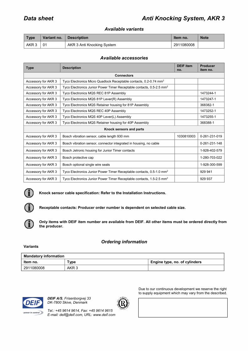
Available variants
Type Variant no. Description Item no. Note
AKR 3 01 AKR 3 Anti Knocking System 2911080008
Available accessories
Type Description DEIF item no.
Producer item no.
Connectors Accessory for AKR 3 Tyco Electronics Micro Quadlock Receptable contacts, 0.2-0.74 mm2 Accessory for AKR 3 Tyco Electronics Junior Power Timer Receptable contacts, 0.5-2.5 mm2 Accessory for AKR 3 Tyco Electronics MQS REC 81P Assembly 1473244-1 Accessory for AKR 3 Tyco Electronics MQS 81P Lever(R) Assembly 1473247-1 Accessory for AKR 3 Tyco Electronics MQS Retainer housing for 81P Assembly 368382-1 Accessory for AKR 3 Tyco Electronics MQS REC 40P Assembly 1473252-1 Accessory for AKR 3 Tyco Electronics MQS 40P Lever(L) Assembly 1473255-1 Accessory for AKR 3 Tyco Electronics MQS Retainer housing for 40P Assembly 368388-1
Knock sensors and parts
Accessory for AKR 3 Bosch vibration sensor, cable length 930 mm 1030810003 0-261-231-019
Accessory for AKR 3 Bosch vibration sensor, connector integrated in housing, no cable 0-261-231-148
Accessory for AKR 3 Bosch Jetronic housing for Junior Timer contacts 1-928-402-579
Accessory for AKR 3 Bosch protective cap 1-280-703-022
Accessory for AKR 3 Bosch optional single wire seals 1-928-300-599
Accessory for AKR 3 Tyco Electronics Junior Power Timer Receptable contacts, 0.5-1.0 mm2 929 941
Accessory for AKR 3 Tyco Electronics Junior Power Timer Receptable contacts, 1.5-2.5 mm2 929 937
Ordering information Variants Mandatory information Item no. Type Engine type, no. of cylinders 2911080008 AKR 3
DEIF A/S, Frisenborgvej 33 DK-7800 Skive, Denmark Tel.: +45 9614 9614, Fax: +45 9614 9615 E-mail: [email protected], URL: www.deif.com
Due to our continuous development we reserve the right to supply equipment which may vary from the described.
Only items with DEIF item number are available from DEIF. All other items must be ordered directly from the producer.
Receptable contacts: Producer order number is dependent on selected cable size.
Knock sensor cable specification: Refer to the Installation Instructions.